WO2014050748A1 - 符号化装置および符号化方法、並びに、復号装置および復号方法 - Google Patents
符号化装置および符号化方法、並びに、復号装置および復号方法 Download PDFInfo
- Publication number
- WO2014050748A1 WO2014050748A1 PCT/JP2013/075518 JP2013075518W WO2014050748A1 WO 2014050748 A1 WO2014050748 A1 WO 2014050748A1 JP 2013075518 W JP2013075518 W JP 2013075518W WO 2014050748 A1 WO2014050748 A1 WO 2014050748A1
- Authority
- WO
- WIPO (PCT)
- Prior art keywords
- information
- reference image
- unit
- image
- encoding
- Prior art date
Links
Images


Classifications
-
- H—ELECTRICITY
- H04—ELECTRIC COMMUNICATION TECHNIQUE
- H04N—PICTORIAL COMMUNICATION, e.g. TELEVISION
- H04N19/00—Methods or arrangements for coding, decoding, compressing or decompressing digital video signals
- H04N19/50—Methods or arrangements for coding, decoding, compressing or decompressing digital video signals using predictive coding
- H04N19/503—Methods or arrangements for coding, decoding, compressing or decompressing digital video signals using predictive coding involving temporal prediction
- H04N19/51—Motion estimation or motion compensation
- H04N19/53—Multi-resolution motion estimation; Hierarchical motion estimation
-
- H—ELECTRICITY
- H04—ELECTRIC COMMUNICATION TECHNIQUE
- H04N—PICTORIAL COMMUNICATION, e.g. TELEVISION
- H04N19/00—Methods or arrangements for coding, decoding, compressing or decompressing digital video signals
- H04N19/30—Methods or arrangements for coding, decoding, compressing or decompressing digital video signals using hierarchical techniques, e.g. scalability
-
- H—ELECTRICITY
- H04—ELECTRIC COMMUNICATION TECHNIQUE
- H04N—PICTORIAL COMMUNICATION, e.g. TELEVISION
- H04N19/00—Methods or arrangements for coding, decoding, compressing or decompressing digital video signals
- H04N19/44—Decoders specially adapted therefor, e.g. video decoders which are asymmetric with respect to the encoder
-
- H—ELECTRICITY
- H04—ELECTRIC COMMUNICATION TECHNIQUE
- H04N—PICTORIAL COMMUNICATION, e.g. TELEVISION
- H04N19/00—Methods or arrangements for coding, decoding, compressing or decompressing digital video signals
- H04N19/50—Methods or arrangements for coding, decoding, compressing or decompressing digital video signals using predictive coding
- H04N19/503—Methods or arrangements for coding, decoding, compressing or decompressing digital video signals using predictive coding involving temporal prediction
-
- H—ELECTRICITY
- H04—ELECTRIC COMMUNICATION TECHNIQUE
- H04N—PICTORIAL COMMUNICATION, e.g. TELEVISION
- H04N19/00—Methods or arrangements for coding, decoding, compressing or decompressing digital video signals
- H04N19/50—Methods or arrangements for coding, decoding, compressing or decompressing digital video signals using predictive coding
- H04N19/593—Methods or arrangements for coding, decoding, compressing or decompressing digital video signals using predictive coding involving spatial prediction techniques
-
- H—ELECTRICITY
- H04—ELECTRIC COMMUNICATION TECHNIQUE
- H04N—PICTORIAL COMMUNICATION, e.g. TELEVISION
- H04N19/00—Methods or arrangements for coding, decoding, compressing or decompressing digital video signals
- H04N19/50—Methods or arrangements for coding, decoding, compressing or decompressing digital video signals using predictive coding
- H04N19/597—Methods or arrangements for coding, decoding, compressing or decompressing digital video signals using predictive coding specially adapted for multi-view video sequence encoding
-
- H—ELECTRICITY
- H04—ELECTRIC COMMUNICATION TECHNIQUE
- H04N—PICTORIAL COMMUNICATION, e.g. TELEVISION
- H04N19/00—Methods or arrangements for coding, decoding, compressing or decompressing digital video signals
- H04N19/70—Methods or arrangements for coding, decoding, compressing or decompressing digital video signals characterised by syntax aspects related to video coding, e.g. related to compression standards
-
- H—ELECTRICITY
- H04—ELECTRIC COMMUNICATION TECHNIQUE
- H04N—PICTORIAL COMMUNICATION, e.g. TELEVISION
- H04N19/00—Methods or arrangements for coding, decoding, compressing or decompressing digital video signals
- H04N19/90—Methods or arrangements for coding, decoding, compressing or decompressing digital video signals using coding techniques not provided for in groups H04N19/10-H04N19/85, e.g. fractals
- H04N19/91—Entropy coding, e.g. variable length coding [VLC] or arithmetic coding
-
- H—ELECTRICITY
- H04—ELECTRIC COMMUNICATION TECHNIQUE
- H04N—PICTORIAL COMMUNICATION, e.g. TELEVISION
- H04N19/00—Methods or arrangements for coding, decoding, compressing or decompressing digital video signals
- H04N19/90—Methods or arrangements for coding, decoding, compressing or decompressing digital video signals using coding techniques not provided for in groups H04N19/10-H04N19/85, e.g. fractals
- H04N19/96—Tree coding, e.g. quad-tree coding
Definitions
- the present technology relates to an encoding device and an encoding method, and a decoding device and a decoding method, and in particular, an encoding device and an encoding method that can share or predict information related to a reference image of an image having a hierarchical structure.
- the present invention relates to a method, a decoding apparatus, and a decoding method.
- MPEG compressed by orthogonal transform such as discrete cosine transform and motion compensation is used for the purpose of efficient transmission and storage of information.
- a device compliant with a method such as Moving (Pictures Experts Group) phase) is becoming popular in both information distribution at broadcast stations and information reception in general households.
- the MPEG2 (ISO / IEC 13818-2) system is defined as a general-purpose image encoding system, and is a standard that covers both interlaced and progressively scanned images, standard resolution images, and high-definition images. Widely used in a wide range of applications for consumer and consumer applications.
- a standard resolution interlaced scanning image having 720 ⁇ 480 pixels is 4 to 8 Mbps
- a high resolution interlaced scanning image having 1920 ⁇ 1088 pixels is 18 to 22 MBps.
- MPEG2 was mainly intended for high-quality encoding suitable for broadcasting, but it did not support encoding methods with a lower code amount (bit rate) than MPEG1, that is, a higher compression rate. With the widespread use of mobile terminals, the need for such an encoding system is expected to increase in the future, and the MPEG4 encoding system has been standardized accordingly. Regarding the MPEG4 image coding system, the standard was approved as an international standard in December 1998 as ISO / IEC 14496-2.
- 26L (ITU-T Q6 / 16 VCEG) is being standardized.
- H. 26L is known to achieve higher encoding efficiency than the conventional encoding schemes such as MPEG2 and MPEG4, although a large amount of calculation is required for encoding and decoding.
- H.264 Based on 26L, H. Standardization that incorporates functions that are not supported by 26L and achieves higher coding efficiency is performed as Joint® Model of Enhanced-Compression® Video® Coding. This standardization was implemented in March 2003 by H.C. It was internationally standardized under the names of H.264 and MPEG-4 Part10 (AVC (Advanced Video Coding)).
- AVC Advanced Video Coding
- HECT High Efficiency Video Coding
- JCTVC Joint Collaboration Collaboration Team Video Coding
- image encoding methods such as MPEG-2 and AVC have a scalable function for hierarchically encoding images. According to the scalable function, it is possible to transmit encoded data according to the processing capability on the decoding side without performing transcoding processing.
- an encoded stream of an image of a base layer (base layer) that is a base layer can be transmitted to a terminal having a low processing capability such as a mobile phone.
- an encoded stream of an image of a base layer and an enhancement layer (enhancement layer) that is a layer other than the base layer may be transmitted to a terminal having high processing capability such as a television receiver or a personal computer. it can.
- the HEVC method also has a scalable function. As described in Non-Patent Document 1, in the HEVC method, in addition to SPS (Sequence Parameter Set) and PPS (Picture Parameter Set), parameters related to the scalable function VPS (Video Parameter Set) is included.
- SPS Sequence Parameter Set
- PPS Physical Parameter Set
- Fig. 1 is a diagram showing an example of the syntax of VPS in HEVC version 1.
- VPS defines only parameters related to temporal scalability as shown in Fig. 1. Has been.
- HEVC version 2 standardization is planned to support scalable functions other than temporal scaleability.
- the present technology has been made in view of such a situation, and makes it possible to share or predict information related to a reference image of an image having a hierarchical structure.
- the encoding device includes first reference image information that is information related to a first reference image used when encoding an image of a first layer of an image having a hierarchical structure, A setting unit configured to set reference image generation information used to generate the first reference image information using second reference image information that is information related to a second reference image of the images of the second hierarchy; An image of one layer is encoded using the first reference image, and an encoding unit that generates encoded data, the encoded data generated by the encoding unit, and the setting unit are set And a transmission unit that transmits the reference image generation information.
- the encoding method according to the first aspect of the present technology corresponds to the encoding device according to the first aspect of the present technology.
- first reference image information that is information relating to a first reference image used when encoding an image of a first layer of an image having a hierarchical structure
- a second layer Reference image generation information used for generating the first reference image information is set using second reference image information that is information related to the second reference image of the first image
- the first layer image is Encoding is performed using the first reference image to generate encoded data, and the encoded data and the reference image generation information are transmitted.
- the decoding device includes first reference image information that is information relating to a first reference image used when encoding an image of a first layer of an image having a hierarchical structure, Reference image generation information used for generating the first reference image information generated using second reference image information that is information related to the second reference image of the image of the first layer, and the first layer Based on a receiving unit that receives encoded data of an image, a generating unit that generates the first reference image information using the reference image generation information, and the first reference image information generated by the generating unit And a decoding unit that decodes the encoded data of the first layer image using the first reference image.
- the decoding method according to the second aspect of the present technology corresponds to the decoding device according to the second aspect of the present technology.
- first reference image information that is information relating to a first reference image used when encoding an image of a first layer of an image having a hierarchical structure
- second layer Reference image generation information used for generating the first reference image information generated using the second reference image information that is information related to the second reference image of the first image
- the first layer image Encoded data is received, the first reference image information is generated using the reference image generation information, and the code of the first layer image is generated based on the generated first reference image information.
- Data is decoded using the first reference picture.
- the encoding device according to the first aspect and the decoding device according to the second aspect can be realized by causing a computer to execute a program.
- a program to be executed by a computer is transmitted through a transmission medium or recorded on a recording medium, Can be provided.
- the encoding device of the first aspect and the decoding device of the second aspect may be independent devices, or may be internal blocks constituting one device.
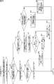
- FIG. 32 is a block diagram illustrating a configuration example of a reference image setting unit in FIG. 31. It is a flowchart explaining the hierarchical decoding process of the decoding apparatus of FIG. It is a flowchart explaining the enhancement image generation process of FIG. It is a flowchart explaining the detail of the decoding process of FIG. It is a flowchart explaining the detail of the production
- FIG. 49 is a block diagram illustrating a configuration example of an encoding unit in FIG. 48. It is a block diagram which shows the structural example of the weight buffer of FIG. 49, and a weight setting part. It is a figure which shows the example of the syntax of the weighting information of an enhancement stream. It is a figure which shows the example of the syntax of the weighting information of an enhancement stream.
- FIG. 49 is a flowchart for describing enhancement stream generation processing of FIG. 48. It is a flowchart explaining the detail of the encoding process of FIG. It is a flowchart explaining the detail of the encoding process of FIG. 55 is a flowchart for describing details of the generation processing of FIG. 54. It is a block diagram which shows the structural example of 2nd Embodiment of the decoding apparatus to which this technique is applied.
- FIG. 58 is a block diagram illustrating a configuration example of an enhancement decoding unit in FIG. 57.
- FIG. 59 is a block diagram illustrating a configuration example of a decoding unit in FIG. 58.
- FIG. 60 is a block diagram illustrating a configuration example of a weight buffer and a weight setting unit in FIG. 59.
- FIG. 58 is a flowchart for describing hierarchical decoding processing of the decoding device in FIG. 57.
- 60 is a flowchart for describing details of a decoding process of the decoding unit in FIG. 59.
- 63 is a flowchart for describing details of the generation processing in FIG. 62. It is a figure explaining the outline
- FIG. 66 is a block diagram illustrating a configuration example of an enhancement encoding unit in FIG. 65.
- FIG. 67 is a block diagram illustrating a configuration example of an encoding unit in FIG. 66.
- FIG. 67 is a diagram illustrating an example of SPS syntax set by the setting unit of FIG. 66. It is a figure which shows the example of the syntax of the slice header of an enhancement stream. It is a figure explaining the effect in an encoding apparatus.
- Fig. 66 is a flowchart for describing hierarchical encoding processing of the encoding device in Fig. 65.
- FIG. 72 is a flowchart for describing details of an SPS setting process in the hierarchical encoding process of FIG. 71.
- FIG. FIG. 72 is a flowchart illustrating details of a copy flag setting process in the enhancement encoding process of FIG. 71.
- FIG. 75 is a block diagram illustrating a configuration example of an enhancement decoding unit in FIG. 74.
- FIG. 76 is a block diagram illustrating a configuration example of a decoding unit in FIG. 75.
- FIG. 75 is a flowchart for describing enhancement image generation processing of an enhancement decoding unit in FIG. 74.
- FIG. 78 is a flowchart for describing details of the SPS extraction processing of FIG. 77.
- 78 is a flowchart for describing details of generation processing in the enhancement decoding processing of FIG. 77. It is a figure which shows the example of the syntax of SPS at the time of another copy flag setting.
- FIG. 1 shows the example of the syntax of the slice header of the enhancement stream at the time of setting mode use. It is a flowchart explaining the SPS setting process at the time of setting mode use. It is a flowchart explaining the copy flag setting process at the time of setting mode use. It is a flowchart explaining the SPS extraction process at the time of setting mode use. It is a flowchart explaining the production
- FIG. 95 is a block diagram illustrating a configuration example of an enhancement encoding unit in FIG. 94.
- FIG. 96 is a block diagram illustrating a configuration example of an encoding unit in FIG. 95.
- FIG. 96 is a diagram illustrating an example of SPS syntax set by the setting unit in FIG. 95. It is a figure which shows the example of the syntax of the slice header of an enhancement stream. It is a figure which shows the example of the syntax of RPS for a partial RPS copy flag.
- FIG. 95 is a flowchart for describing SPS setting processing of the encoding device in FIG. 94.
- FIG. FIG. 95 is a flowchart for describing details of a copy flag setting process of the encoding device in FIG. 94.
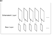
- FIG. 2 is a diagram for explaining spatial scalability.
- spatial scalability is a scalable function that encodes an image by layering it at a spatial resolution.
- a low resolution image is encoded as a base layer image
- a difference image between the high resolution image and the low resolution image is encoded as an enhancement layer image.
- the encoding device transmits only the encoded data of the base layer image to the decoding device with low processing capability, so that the decoding device can generate a low-resolution image. Further, the encoding device transmits the encoded data of the base layer and enhancement layer images to the decoding device having high processing capability, so that the decoding device decodes and synthesizes the base layer and enhancement layer images. High-resolution images can be generated.
- FIG. 3 is a diagram for explaining temporal scalability.
- temporal scalability is a scalable function that encodes images by layering them at the frame rate.
- an image with a low frame rate (7.5 fps in the example of FIG. 3) is encoded as a base layer image.
- a difference image between the image at the medium frame rate (15 fps in the example of FIG. 3) and the image at the low frame rate is encoded as an enhancement layer image.
- the difference image between the image at the high frame rate (30 fps in the example of FIG. 3) and the image at the medium frame rate is encoded as an enhancement layer image.
- the encoding device transmits only the encoded data of the base layer image to the decoding device with low processing capability, so that the decoding device can generate a low frame rate image. Further, the encoding device transmits the encoded data of the base layer and enhancement layer images to the decoding device having high processing capability, so that the decoding device decodes and synthesizes the base layer and enhancement layer images. High frame rate or medium frame rate images can be generated.
- FIG. 4 is a diagram for explaining SNR scalability.
- SNR scalability is a scalable function that encodes an image by layering it with SNR (signal-noise ratio). Specifically, in SNR scalability, a low SNR image is encoded as a base layer image, and a difference image between a high SNR image and a low SNR image is encoded as an enhancement layer image.
- the encoding device transmits only the encoded data of the base layer image to the decoding device with low processing capability, so that the decoding device can generate a low SNR image, that is, a low quality image. it can. Further, the encoding device transmits the encoded data of the base layer and enhancement layer images to the decoding device having high processing capability, so that the decoding device decodes and synthesizes the base layer and enhancement layer images.
- a high SNR image that is, a high-quality image can be generated.
- bit-depth scalability for encoding an image by layering the number of bits.
- an 8-bit video image is used as a base layer image
- a difference between a 10-bit video image and an 8-bit video image is used as an enhancement layer image and encoded.
- the YUV420 image is set as the base layer image
- the difference image between the YUV422 image and the YUV420 image is set as the enhancement layer image and encoded.
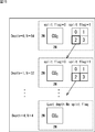
- FIG. 5 is a diagram illustrating an overview of the first embodiment to which the present technology is applied.
- reference image specifying information information for specifying a reference image as information about a reference image (hereinafter referred to as reference image specifying information) is shared between different hierarchies as well as between the same hierarchies. is expected.
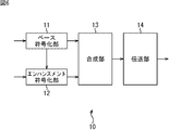
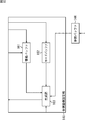
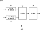
- FIG. 6 is a block diagram illustrating a configuration example of the first embodiment of the encoding device to which the present technology is applied.
- the 6 includes a base encoding unit 11, an enhancement encoding unit 12, a synthesizing unit 13, and a transmission unit 14, and encodes an image using a scalable function in accordance with a scheme equivalent to the HEVC scheme.
- a base layer image (hereinafter referred to as a base image) is input to the base encoding unit 11 of the encoding device 10 from the outside.
- the base encoding unit 11 is configured in the same manner as a conventional HEVC encoding device, and encodes a base image using the HEVC method.
- the base encoding unit 11 supplies the reference image specifying information of the reference image used when encoding the base image to the enhancement encoding unit 12.
- the base encoding unit 11 supplies an encoded stream including encoded data, SPS, PPS, and the like obtained as a result of encoding to the synthesizing unit 13 as a base stream.
- the enhancement coding unit 12 receives an enhancement layer image (hereinafter referred to as an enhancement image) from the outside.
- the enhancement encoding unit 12 encodes the enhancement image by a method according to the HEVC method.
- the enhancement encoding unit 12 uses the reference image specifying information of the base image and the reference image specifying information of the reference image used when encoding the enhancement image to generate reference image specifying information of the enhancement image.
- Reference image specific generation information reference image generation information
- the enhancement encoding unit 12 generates an encoded stream by adding reference image specifying generation information or the like to the encoded data of the enhancement image, and supplies the encoded stream to the synthesizing unit 13 as an enhancement stream.
- the synthesizing unit 13 synthesizes the base stream supplied from the base encoding unit 11 and the enhancement stream supplied from the enhancement encoding unit 12, and adds a VPS or the like to generate an encoded stream of all layers.
- the synthesizing unit 13 supplies the encoded stream of all layers to the transmission unit 14.
- the transmission unit 14 transmits the encoded stream of all layers supplied from the synthesis unit 13 to a decoding device described later.
- the encoding apparatus 10 shall transmit the encoding stream of all the layers here, it can also transmit only a base stream as needed.
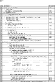
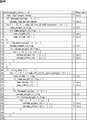
- Example of base stream SPS syntax 7 and 8 are diagrams illustrating examples of SPS syntax included in the base stream.
- the SPS of the base stream relates to RPS (reference picture set) that is reference picture specifying information of a short term of a GOP (Group of picture) corresponding to the SPS. Contains information. Specifically, the SPS includes the number of RPSs (num_short_term_ref_pic_sets) included in the SPS and RPS (short_term_ref_pic_set). An index is assigned to RPS in order from 0.
- the SPS describes information related to long-term reference image specifying information. Specifically, the SPS includes a long-term flag (long_term_ref_pics_present_flag) indicating whether or not a long-term reference image is usable.
- long_term_ref_pics_present_flag indicating whether or not a long-term reference image is usable.
- the SPS when the long-term flag is 1 indicating that a long-term reference image is usable, the SPS includes the number of long-term reference image specifying information (num_long_term_ref_pics_sps) included in the SPS. Also included is information (lt_ref_pic_poc_lsb_sps) indicating the least significant bit of the POC (Picture Order Count) of the reference image as long term reference image specifying information. Furthermore, a reference flag (used_by_curr_pic_lt_sps_flag) indicating whether or not the reference image specified by the reference image specifying information is not referred to by itself is described. An index is assigned to the reference image specifying information of long term in order from 0.
- reference image specifying information when it is not necessary to particularly distinguish the RPS and long-term reference image specifying information, they are simply referred to as reference image specifying information.
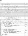
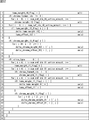
- Example of syntax of slice header of base stream 9 to 11 are diagrams illustrating an example of syntax of a slice header that is a header added to encoded data included in a base stream in units of slices.
- the slice header of the base stream includes an RPS flag (short_term_ref_pic_set_sps_flag) indicating that the RPS of the corresponding slice is an RPS included in the SPS.
- RPS flag short_term_ref_pic_set_sps_flag
- the RPS flag is 0 indicating that the RPS of the corresponding slice is not the RPS included in the SPS
- the RPS of the corresponding slice is included in the slice header.
- RPS short_term_ref_pic_set (num_short_term_ref_pic_sets)
- whose index is num_short_term_ref_pic_sets.
- the slice header has an RPS index ( short_term_ref_pic_set_idx).
- the long term flag included in the corresponding SPS is 1, the number of reference image specifying information of the long term included in the SPS is indicated in the slice header.
- the number within SPS (num_long_term_sps) and the number outside SPS (num_long_term_pics), which is the number of long-term reference image specifying information included in the slice header, are included.
- the index (lt_idx_sps) of the long-term reference image specifying information included in the SPS among the long-term reference image specifying information in the corresponding slice. Is included.
- the slice header includes a reference image as long-term reference image specifying information not included in the SPS among the long-term reference image specifying information in the corresponding slice.
- Information (poc_lsb_sps) indicating the least significant bit of the POC and a reference flag (used_by_curr_pic_lt_flag) are included.
- FIG. 12 is a diagram illustrating an example of RPS syntax of a base stream.
- the RPS includes inter_ref_pic_set_prediction_flag.
- inter_ref_pic_set_prediction_flag indicates whether the reference image specifying information of the previous image that is an image preceding the encoding target image in the GOP of the encoding target image is used as the reference image specifying information of the encoding target image. Reference information to be shown.
- the reference information is 1 when indicating that the reference image specifying information of the previous image is used as the reference image specifying information of the encoding target image, and the reference image specifying information of the previous image is used as the reference image specifying information of the encoding target image. 0 indicates that it is not used.
- the RPS includes the previous image specifying information (delta_idx_minus1) for specifying the previous image.
- delta_idx_minus1 is a value obtained by subtracting 1 from the value obtained by subtracting the encoding number of the previous image from the encoding number (Coding Order) of the encoding target image.
- the encoding number is a number assigned to each image in the GOP from a small value in the encoding order.
- the RPS includes the difference between the reference image specifying information (POC) of the previous image and the reference image specifying information (POC) of the encoding target image.
- the sign (delta_rps_sign) and the absolute value of the difference (abs_delta_rps_minus1) are included.
- the RPS includes a flag (used_by_curr_pic_lt_flag) indicating whether or not to use the reference image specified by the reference image specifying information. Also, as shown in the 10th and 11th lines, when the flag (used_by_curr_pic_lt_flag) is 0 indicating that the reference image specified by the reference image specifying information is not used, the reference image is the RPS. A flag (use_delta_flag) indicating whether or not it is included is included.
- the RPS includes information indicating the number of reference images, POC, and the like.
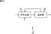
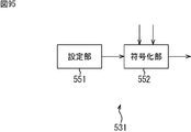
- FIG. 13 is a block diagram illustrating a configuration example of the enhancement encoding unit 12 of FIG.
- the enhancement encoding unit 12 in FIG. 13 includes an encoding unit 21 and a setting unit 22.
- the encoding unit 21 of the enhancement encoding unit 12 uses an enhancement image for each frame input from the outside as an input signal.
- the encoding unit 21 encodes the input signal by a method according to the HEVC method with reference to the reference image specifying information from the base encoding unit 11, the reference image specifying generation information from the setting unit 22, and the like.
- the encoding unit 21 supplies the encoded data obtained as a result to the setting unit 22.
- the setting unit 22 sets reference image specific generation information.
- reference image specification generation information an index is assigned in order from 0 to the difference between the reference image specification information and the reference image specification information.
- the setting unit 22 supplies the reference image specifying generation information to the encoding unit 21.
- the setting unit 22 sets SPS, PPS, and the like including reference image specific generation information.
- the setting unit 22 generates an encoded stream from the set SPS and PPS and the encoded data supplied from the encoding unit 21, and supplies the encoded stream to the synthesizing unit 13 as an enhancement stream.
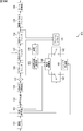
- FIG. 14 is a block diagram illustrating a configuration example of the encoding unit 21 in FIG. 13.
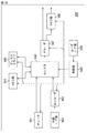
- a / D conversion unit 31 includes an A / D conversion unit 31, a screen rearrangement buffer 32, a calculation unit 33, an orthogonal transformation unit 34, a quantization unit 35, a lossless encoding unit 36, an accumulation buffer 37, and an inverse quantization unit. 38, inverse orthogonal transform unit 39, addition unit 40, deblock filter 41, adaptive offset filter 42, adaptive loop filter 43, frame memory 44, switch 45, intra prediction unit 46, motion prediction / compensation unit 47, prediction image selection unit 48, a reference buffer 49, a reference image setting unit 50, and a rate control unit 51.
- the A / D conversion unit 31 of the encoding unit 21 performs A / D conversion on an image in frame units input as an input signal, and outputs and stores the image in the screen rearrangement buffer 32.
- the screen rearrangement buffer 32 rearranges the stored frame-by-frame images in the order for encoding according to the GOP structure, the arithmetic unit 33, the intra prediction unit 46, and the motion prediction / compensation unit. Output to 47.
- the calculation unit 33 functions as an encoding unit, and performs encoding by calculating the difference between the predicted image supplied from the predicted image selection unit 48 and the image to be encoded output from the screen rearrangement buffer 32. . Specifically, the calculation unit 33 performs encoding by subtracting the predicted image supplied from the predicted image selection unit 48 from the encoding target image output from the screen rearrangement buffer 32. The computing unit 33 outputs the resulting image to the orthogonal transform unit 34 as residual information. When the predicted image is not supplied from the predicted image selection unit 48, the calculation unit 33 outputs the image read from the screen rearrangement buffer 32 as it is to the orthogonal transform unit 34 as residual information.
- the orthogonal transform unit 34 performs orthogonal transform on the residual information from the calculation unit 33 and supplies the generated orthogonal transform coefficient to the quantization unit 35.
- the quantization unit 35 quantizes the orthogonal transform coefficient supplied from the orthogonal transform unit 34 and supplies the resulting coefficient to the lossless encoding unit 36.
- the lossless encoding unit 36 acquires information indicating the optimal intra prediction mode (hereinafter referred to as intra prediction mode information) from the intra prediction unit 46. Further, the lossless encoding unit 36 acquires information indicating the optimal inter prediction mode (hereinafter referred to as inter prediction mode information), a motion vector, and the like supplied from the motion prediction / compensation unit 47 from the motion prediction / compensation unit 47. Further, the lossless encoding unit 36 acquires reference image specifying generation information, an RPS flag, and the like from the reference image setting unit 50.
- the lossless encoding unit 36 acquires offset filter information regarding the offset filter from the adaptive offset filter 42 and acquires filter coefficients from the adaptive loop filter 43.
- the lossless encoding unit 36 performs variable length coding (for example, CAVLC (Context-Adaptive Variable Length Length Coding)) and arithmetic coding (for example, CABAC) on the quantized coefficients supplied from the quantization unit 35. (Context-Adaptive
- variable length coding for example, CAVLC (Context-Adaptive Variable Length Length Coding)
- CABAC arithmetic coding
- the lossless encoding unit 36 uses intra prediction mode information or inter prediction mode information, a motion vector, reference image specifying generation information, an RPS flag, offset filter information, and a filter coefficient as encoding information related to encoding. Lossless encoding.
- the lossless encoding unit 36 adds the slice header to the encoded data using the lossless encoded information as a slice header and the lossless encoded coefficient as encoded data.
- the lossless encoding unit 36 supplies the encoded data to which the slice header is added to the accumulation buffer 37 for accumulation.
- the accumulation buffer 37 temporarily stores the encoded data supplied from the lossless encoding unit 36. Further, the accumulation buffer 37 supplies the stored encoded data to the setting unit 22 in FIG.
- the quantized coefficient output from the quantizing unit 35 is also input to the inverse quantizing unit 38.
- the inverse quantization unit 38 performs inverse quantization on the coefficient quantized by the quantization unit 35, and supplies the orthogonal transform coefficient obtained as a result to the inverse orthogonal transform unit 39.
- the inverse orthogonal transform unit 39 performs fourth-order inverse orthogonal transform on the orthogonal transform coefficient supplied from the inverse quantization unit 38 and supplies residual information obtained as a result to the addition unit 40.
- the addition unit 40 adds the residual information supplied from the inverse orthogonal transform unit 39 and the prediction image supplied from the prediction image selection unit 48 to obtain a locally decoded image.
- the adding unit 40 sets the residual information supplied from the inverse orthogonal transform unit 39 as a locally decoded image.
- the adder 40 supplies the locally decoded image to the deblocking filter 41 and also supplies it to the frame memory 44 for accumulation.
- the deblocking filter 41 performs adaptive deblocking filter processing for removing block distortion on the locally decoded image supplied from the adding unit 40 and supplies the resulting image to the adaptive offset filter 42. .
- the adaptive offset filter 42 performs an adaptive offset filter (SAO (Sample adaptive offset)) process that mainly removes ringing on the image after the adaptive deblock filter process by the deblock filter 41.
- SAO Sample adaptive offset
- the adaptive offset filter 42 determines the type of adaptive offset filter processing for each LCU (Largest Coding Unit) which is the maximum coding unit, and obtains an offset used in the adaptive offset filter processing.
- the adaptive offset filter 42 performs the determined type of adaptive offset filter processing on the image after the adaptive deblocking filter processing, using the obtained offset. Then, the adaptive offset filter 42 supplies the image after the adaptive offset filter processing to the adaptive loop filter 43.
- the adaptive offset filter 42 has a buffer for storing the offset.
- the adaptive offset filter 42 determines whether the offset used for the adaptive offset filter processing is already stored in the buffer for each LCU.
- the adaptive offset filter 42 determines that the offset used for the adaptive offset filter processing is already stored in the buffer, the adaptive offset filter 42 stores a storage flag indicating whether the offset is stored in the buffer, and the offset is stored in the buffer. Is set to a value (in this case, 1).
- the adaptive offset filter 42 stores, for each LCU, a storage flag set to 1, an index indicating the storage position of the offset in the buffer, and type information indicating the type of adaptive offset filter processing that has been performed. To the lossless encoding unit 36.
- the adaptive offset filter 42 stores the offset in the buffer.
- the adaptive offset filter 42 sets the storage flag to a value (in this case, 0) indicating that the offset is not stored in the buffer. Then, the adaptive offset filter 42 supplies the storage flag, offset, and type information set to 0 to the lossless encoding unit 36 as offset filter information for each LCU.
- the adaptive loop filter 43 is configured by, for example, a two-dimensional Wiener filter.
- the adaptive loop filter 43 performs an adaptive loop filter (ALF (Adaptive Loop Filter)) process for each LCU, for example, on the image after the adaptive offset filter process supplied from the adaptive offset filter 42.
- ALF Adaptive Loop Filter
- the adaptive loop filter 43 is configured so that the residual of the original image that is the image output from the screen rearrangement buffer 32 and the image after the adaptive loop filter processing is minimized for each LCU. A filter coefficient used in the processing is calculated. Then, the adaptive loop filter 43 performs adaptive loop filter processing for each LCU using the calculated filter coefficient on the image after the adaptive offset filter processing.
- the adaptive loop filter 43 supplies the image after the adaptive loop filter processing to the frame memory 44.
- the adaptive loop filter 43 supplies the filter coefficient to the lossless encoding unit 36.
- the adaptive loop filter processing is performed for each LCU, but the processing unit of the adaptive loop filter processing is not limited to the LCU. However, the processing can be efficiently performed by combining the processing units of the adaptive offset filter 42 and the adaptive loop filter 43.
- the frame memory 44 stores the image supplied from the adaptive loop filter 43 and the image supplied from the adder 40.
- the image stored in the frame memory 44 is output as a reference image to the intra prediction unit 46 or the motion prediction / compensation unit 47 via the switch 45.
- the intra prediction unit 46 uses the reference image read from the frame memory 44 via the switch 45 to perform intra prediction processing for all candidate intra prediction modes.
- the intra prediction unit 46 calculates cost function values for all candidate intra prediction modes based on the image read from the screen rearrangement buffer 32 and the predicted image generated as a result of the intra prediction process. (Details will be described later). Then, the intra prediction unit 46 determines the intra prediction mode that minimizes the cost function value as the optimal intra prediction mode.
- the intra prediction unit 46 supplies the predicted image generated in the optimal intra prediction mode and the corresponding cost function value to the predicted image selection unit 48.
- the intra prediction unit 46 supplies the intra prediction mode information to the lossless encoding unit 36 when the prediction image selection unit 48 is notified of selection of a prediction image generated in the optimal intra prediction mode.
- the cost function value is also called RD (Rate Distortion) cost. It is calculated based on a method of either High Complexity mode or Low Complexity mode as defined by JM (Joint Model) which is reference software in the H.264 / AVC format. H. Reference software in the H.264 / AVC format is published at http://iphome.hhi.de/suehring/tml/index.htm.
- D is the difference (distortion) between the original image and the decoded image
- R is the generated code amount including even the coefficient of orthogonal transformation
- ⁇ is the Lagrange undetermined multiplier given as a function of the quantization parameter QP.
- D is the difference (distortion) between the original image and the predicted image
- Header_Bit is the code amount of the encoding information
- QPtoQuant is a function given as a function of the quantization parameter QP.
- the motion prediction / compensation unit 47 performs motion prediction / compensation processing for all candidate inter prediction modes. Specifically, the motion prediction / compensation unit 47 selects all candidate inter prediction modes based on the image supplied from the screen rearrangement buffer 32 and the reference image read from the frame memory 44 via the switch 45. The motion vector is detected. The reference image is set by a user, for example. The motion prediction / compensation unit 47 performs compensation processing on the reference image based on the detected motion vector, and generates a predicted image.
- the motion prediction / compensation unit 47 calculates the cost function value for all candidate inter prediction modes based on the image and the predicted image supplied from the screen rearrangement buffer 32, and the cost function value. Is determined to be the optimal inter prediction mode. Then, the motion prediction / compensation unit 47 supplies the cost function value of the optimal inter prediction mode and the corresponding prediction image to the prediction image selection unit 48. In addition, the motion prediction / compensation unit 47, when notified of the selection of the predicted image generated in the optimal inter prediction mode from the predicted image selection unit 48, the inter prediction mode information, the corresponding motion vector, etc., is lossless encoding unit 36. The reference image specifying information is output to the reference image setting unit 50.
- the predicted image selection unit 48 Based on the cost function values supplied from the intra prediction unit 46 and the motion prediction / compensation unit 47, the predicted image selection unit 48 has a smaller corresponding cost function value of the optimal intra prediction mode and the optimal inter prediction mode. Are determined as the optimum prediction mode. Then, the predicted image selection unit 48 supplies the predicted image in the optimal prediction mode to the calculation unit 33 and the addition unit 40. Further, the predicted image selection unit 48 notifies the intra prediction unit 46 or the motion prediction / compensation unit 47 of selection of the predicted image in the optimal prediction mode.
- the reference buffer 49 stores the reference image specifying information of the reference image used at the time of encoding the base image supplied from the base encoding unit 11 of FIG.
- the reference image setting unit 50 compares the reference image specifying information supplied from the motion prediction / compensation unit 47 with the reference image specifying information stored in the reference buffer 49, and sets the prediction mode of the reference image specifying information of the enhancement image. decide.
- the prediction mode of the reference image specifying information includes a copy mode, a difference prediction mode, and a non-prediction mode.
- the copy mode is a prediction mode in which the reference image specifying information of the reference layer that is another layer to be referred to (the base layer in this case) is used as the reference image specifying information of the enhancement image.
- the difference prediction mode is a prediction in which the reference image specifying information of the enhancement image is predicted by adding the difference between the reference image specifying information of the enhancement image and the reference image specifying information of the reference layer and the reference image specifying information of the reference layer.
- the non-prediction mode is a prediction mode in which the reference image specifying information of the enhancement image is set independently of the reference image specifying information of the reference layer.
- the reference image setting unit 50 is the copy mode of the reference image specifying information as the reference image specifying generation information supplied from the setting unit 22 of FIG. At this time, 1 as the RPS flag is supplied to the lossless encoding unit 36.
- the prediction mode of the reference image specifying information as the reference image specifying generation information supplied from the setting unit 22 is not the copy mode, 0 is supplied as the RPS flag to the lossless encoding unit 36 and the copy mode is referred to. This is set as image specific generation information and supplied to the lossless encoding unit 36.
- the reference image setting unit 50 calculates the difference between the reference image specifying information of the enhancement image and the reference image specifying information of the base image. Then, the reference image setting unit 50 compares the calculated difference of the reference image specifying information with the difference of the reference image specifying information as the reference image specifying generation information supplied from the setting unit 22.
- the reference image setting unit 50 recognizes the corresponding index, supplies 1 as the RPS flag to the lossless encoding unit 36, and sets the index as reference image specifying generation information. And supplied to the lossless encoding unit 36.
- the reference image setting unit 50 supplies 0 as the RPS flag to the lossless encoding unit 36, and uses the calculated difference of the reference image specifying information as the reference image specifying generation information. This is set and supplied to the lossless encoding unit 36.
- the reference image setting unit 50 and the reference image specifying information as the reference image specifying generation information supplied from the setting unit 22 and the reference image specifying information supplied from the setting unit 22 Compare with information. Then, when both reference image specifying information is the same, the reference image setting unit 50 recognizes the corresponding index, supplies 1 as the RPS flag to the lossless encoding unit 36, and generates the index as the reference image specifying generation. Information is set and supplied to the lossless encoding unit 36.
- the reference image setting part 50 supplies 0 as an RPS flag to the lossless encoding part 36, and also uses the reference image specific information of an enhancement image as reference image specific generation information. And is supplied to the lossless encoding unit 36.
- the rate control unit 51 controls the quantization operation rate of the quantization unit 35 based on the encoded data stored in the storage buffer 37 so that overflow or underflow does not occur.
- FIG. 15 is a diagram for explaining Coding UNIT (CU), which is a coding unit in the HEVC scheme.
- CU is defined as a coding unit.
- the CU is also called Coding Tree Block (CTB) and plays the same role as a macroblock in the AVC method.
- CTB Coding Tree Block
- the CU is divided into Prediction Unit (PU) that is a unit of intra prediction or inter prediction, or is divided into Transform Unit (TU) that is a unit of orthogonal transformation.
- PU Prediction Unit
- TU Transform Unit
- the size of the CU is a square represented by a power-of-two pixel that is variable for each sequence.
- the size of the LCU (Largest Coding Unit) that is the largest CU is 128, and the size of the SCU (Smallest Coding Unit) that is the smallest CU is eight. Therefore, the layer depth (depth) of a 2N ⁇ 2N size CU layered for each N is 0 to 4, and the number of layer depths is 5. Further, when the value of split_flag is 1, the 2N ⁇ 2N size CU is divided into N ⁇ N size CUs, which are one layer below.
- Non-Patent Document 1 Information specifying the LCU and SCU sizes is included in the SPS. Details of the CU are described in Non-Patent Document 1.
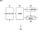
- FIG. 16 is a block diagram illustrating a configuration example of the reference image setting unit 50 in FIG.
- 16 includes an acquisition unit 71, a determination unit 72, and a generation unit 73.
- the acquisition unit 71 of the reference image setting unit 50 acquires reference image specifying information from the motion prediction / compensation unit 47 of FIG. 14 and supplies the reference image specifying information to the determination unit 72 and the generation unit 73.
- the determination unit 72 reads the reference image specifying information of the base image from the reference buffer 49.
- the determining unit 72 compares the read reference image specifying information of the base image with the reference image specifying information supplied from the acquiring unit 71. Then, when the reference image identification information of the read base image is the same as the reference image identification information supplied from the acquisition unit 71, the determination unit 72 determines the prediction mode of the reference image identification information as the copy mode. .
- the determination unit 72 supplies the copy mode to the generation unit 73.
- the determination unit 72 determines whether the prediction mode of the reference image specifying information supplied as the reference image specifying generation information from the setting unit 22 in FIG. 13 is the copy mode. When it is determined that the prediction mode of the reference image specifying information supplied as the reference image specifying generation information is the copy mode, the determining unit 72 supplies 1 as the RPS flag to the lossless encoding unit 36 in FIG. On the other hand, when it is determined that the prediction mode of the reference image specific information supplied as the reference image specific generation information is not the copy mode, the determination unit 72 supplies 0 as the RPS flag to the lossless encoding unit 36, The copy mode is supplied to the lossless encoding unit 36 as reference image specifying generation information.
- the generation unit 73 reads the reference image specifying information of the base image from the reference buffer 49. Based on the input from the user, the generation unit 73 determines the prediction mode of the reference image specifying information to be the difference prediction mode or the non-prediction mode, and supplies it to the lossless encoding unit 36 as reference image specifying generation information.
- the generation unit 73 calculates a difference between the read reference image specifying information of the base image and the reference image specifying information supplied from the acquisition unit 71. To do. Then, the generation unit 73 compares the calculated difference of the reference image specifying information with the difference of the reference image specifying information as the reference image specifying generation information supplied from the setting unit 22.
- the generation unit 73 recognizes the corresponding index, supplies 1 as the RPS flag to the lossless encoding unit 36, and uses the index as the reference image specifying generation information, and the lossless encoding unit 36. To supply.
- the generation unit 73 supplies 0 as the RPS flag to the lossless encoding unit 36, and supplies the calculated difference to the lossless encoding unit 36 as reference image specifying generation information. To do.
- the generation unit 73 uses the reference image specifying information supplied from the acquisition unit 71 and the reference image specifying generation information supplied from the setting unit 22. To the reference image specifying information. Then, when both reference image specifying information is the same, the generating unit 73 recognizes the corresponding index, supplies 1 as the RPS flag to the lossless encoding unit 36, and uses the index as the reference image specifying generating information. This is supplied to the lossless encoding unit 36.
- the generation unit 73 supplies 0 as the RPS flag to the lossless encoding unit 36 and uses the reference image specifying information supplied from the acquisition unit 71 as the reference image specifying.
- the generated information is supplied to the lossless encoding unit 36.
- Example of SPS syntax for enhancement stream 17 and 18 are diagrams illustrating examples of SPS syntax set by the setting unit 22 of FIG.
- the SPS includes RPS prediction mode information (short_term_ref_pic_pred_mode) representing the prediction mode of RPS as reference image specifying generation information.
- the RPS prediction mode information is 0 when representing the copy mode, 1 when representing the differential prediction mode, and 2 when representing the non-prediction mode.
- the SPS when the RPS prediction mode information is other than 0, the SPS includes RPS and RPS differences for each RPS prediction mode. Indexes are assigned in order from 0 to the difference between RPS and RPS.
- the SPS includes a long-term flag (long_term_ref_pics_present_flag) as in the SPS of the base stream.
- the SPS has long term prediction mode information indicating the prediction mode of the reference image specifying information of the long term as reference image specifying generation information ( long_term_ref_pic_pred_mode) is included.
- the long term prediction mode information (long_term_ref_pic_pred_mode) is 0 when representing the copy mode, 1 when representing the differential prediction mode, and 2 when representing the non-prediction mode.
- the SPS includes the number of long-term reference image specifying information similar to the SPS of the base stream, the long-term reference image specifying Information and a reference flag are included as reference image specifying generation information.
- An index is assigned to the reference image specifying information of long term in order from 0.
- the SPS includes the number of long-term reference image specifying information included in the SPS and the long included in the SPS of the reference layer.
- Difference between the number of reference image identification information for term (diff_num_long_term_ref_pics_sps), difference between the reference image identification information for long term and the reference image identification information for long term included in the SPS of the reference layer (diff_lt_ref_pic_poc_lsb_sps) Is included as the reference image specific generation information.
- the SPS of the enhancement stream does not include a reference flag, and the reference flag is a reference layer reference flag.
- FIGS. 19 to 21 are diagrams illustrating a configuration example of the syntax of the slice header of the enhancement stream.
- the slice header of the enhancement stream includes an RPS flag, like the slice header of the base stream. Further, as shown in the 19th and 20th lines, when the RPS flag is 0, the RPS mode information of the corresponding slice is included in the slice header as the reference image specifying generation information.
- the slice header includes the RPS or RPS difference of the corresponding slice as an index for each RPS prediction mode. Is included as short_term_ref_pic_set where num_short_term_ref_pic_sets.
- the slice header contains the difference between the RPS or RPS of the corresponding slice.
- An index (short_term_ref_pic_set_idx) is included.
- the slice header includes long term prediction mode information as reference image specific generation information.
- the long term prediction mode information is 2
- the number in SPS and the number outside SPS are included in the slice header, as in the base stream, in the reference image specifying generation information. Included as
- the index (lt_idx_sps), the information (poc_lsb_sps), and the reference flag (used_by_curr_pic_lt_flag) are included in the slice header, as in the base stream. Included as
- the most significant bit flag (delta_poc_msb_cycle_lt) indicating whether or not the most significant bit information (delta_poc_msb_cycle_lt) indicating the most significant bit of the POC of the long-term reference image exists in the slice header.
- delta_poc_msb_present_flag is included.
- the long term prediction mode information is 1
- the slice header includes a difference between an index (lt_idx_sps), information (poc_lsb_lt), and reference layer information (poc_lsb_lt). (diff_poc_lsb_lt) is included as reference image specific generation information.
- the slice header of the enhancement stream does not include the reference flag and the most significant bit flag, and the reference flag and the most significant bit flag respectively include the reference layer reference flag and the most significant bit flag.
- the upper bit flag When the long-term prediction mode information is 1, the slice header of the enhancement stream does not include the reference flag and the most significant bit flag, and the reference flag and the most significant bit flag respectively include the reference layer reference flag and the most significant bit flag. The upper bit flag.
- the slice header includes the most significant bit information of the corresponding slice and the most significant bit information of the reference layer.
- the difference (diff_delta_poc_msb_cycle_lt) is included.
- FIG. 22 is a diagram illustrating an example of RPS syntax of an enhancement stream.
- the enhancement stream RPS includes reference information in the same manner as the base stream RPS.
- the RPS of the enhancement stream includes the previous image specifying information, code (like the RPS of the base stream). delta_rps_sign), an absolute value (abs_delta_rps_minus1), a flag (used_by_curr_pic_lt_flag), and a flag (use_delta_flag) are included as reference image specific generation information.
- the RPS when the reference information is 1 and the RPS prediction mode is 1, the RPS includes the previous image specifying information of the corresponding slice and the previous image specifying information of the reference layer. Difference (diff_delta_idx_minus1) and the difference (diff_abs_delta_rps_minus1) between the absolute value of the corresponding slice (abs_delta_rps_minus1) and the absolute value of the reference layer (abs_delta_rps_minus1).
- the slice header of the enhancement stream does not include the code (delta_rps_sign), the flag (used_by_curr_pic_lt_flag), and the flag (use_delta_flag), and the code (delta_rps_sign), the flag (used_by_curr_pic_lt_flag), And the flag (use_delta_flag) are a reference layer code (delta_rps_sign), a flag (used_by_curr_pic_lt_flag), and a flag (use_delta_flag), respectively.
- the RPS includes the number of reference images, the POC, and the like as in the RPS of the base stream. Contains information. Further, as shown in the 33rd to 40th lines, when the reference information is 0 and the RPS prediction mode is 1, the RPS includes information such as the number of reference images of the corresponding slice, information on the POC, and the reference. Differences from the number of layer reference images and information such as POC are included.
- FIG. 23 is a diagram illustrating an example of VPS syntax.
- the VPS includes information (vps_max_layer_minus1) indicating the number of layers of scalability. Further, as shown in the seventh line, the VPS includes information (vps_max_sub_layer_minus1) indicating the number of layers of temporalabilityscalability as in the conventional case.
- the VPS includes 0 as the difference (diff_ref_layer [0]) between the base layer and the reference layer as information for specifying the base layer whose index is 0. Further, as shown in the 16th and 17th lines, the VPS includes a difference (diff_ref_layer) of each enhancement layer.
- the reference layer ref_layer is expressed by the following equation (3) using the difference diff_ref_layer.
- the enhancement stream is generated without referring to the reference image specifying information of the other layers, like the base stream.
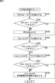
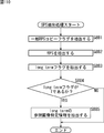
- FIG. 24 is a flowchart illustrating the hierarchical encoding process of the encoding device 10 of FIG. This hierarchical encoding process is started when a base image and an enhancement image are input from the outside.
- the base encoding unit 11 of the encoding device 10 encodes a base image input from the outside using the HEVC method.
- the base encoding unit 11 supplies the reference image specifying information of the reference image used when encoding the base image to the enhancement encoding unit 12.
- the base encoding unit 11 supplies a base stream including encoded data, SPS, PPS, and the like obtained as a result of encoding to the synthesizing unit 13 as a base stream.
- step S2 the enhancement encoding unit 12 performs an enhancement stream generation process for generating an enhancement stream from an enhancement image input from the outside. Details of the enhancement stream generation processing will be described with reference to FIG.
- step S3 the synthesizing unit 13 synthesizes the base stream supplied from the base encoding unit 11 and the enhancement stream supplied from the enhancement encoding unit 12, adds VPS and the like, and adds the encoded stream of all layers. Generate.
- the synthesizing unit 13 supplies the encoded stream of all layers to the transmission unit 14.
- step S4 the transmission unit 14 transmits the encoded stream of all layers supplied from the synthesis unit 13 to a decoding device to be described later.
- FIG. 25 is a flowchart for explaining the details of the enhancement stream generation process in step S2 of FIG.
- the setting unit 22 of the enhancement encoding unit 12 sets reference image specifying generation information and supplies the reference image specifying generation information to the encoding unit 21.
- the encoding unit 21 performs an encoding process that encodes an enhancement image in units of frames input from the outside as an input signal by a method according to the HEVC method. Details of this encoding process will be described with reference to FIGS. 26 and 27 described later.
- step S12 the setting unit 22 sets the SPS including the reference image specific generation information set in step S10.
- step S13 the setting unit 22 sets the PPS.
- step S ⁇ b> 14 the setting unit 22 generates an enhancement stream from the set SPS and PPS and the encoded data supplied from the encoding unit 21.
- step S15 the setting unit 22 supplies the enhancement stream to the synthesis unit 13, and ends the process.
- 26 and 27 are flowcharts illustrating details of the encoding process in step S11 of FIG.
- the A / D conversion unit 31 of the encoding unit 21 performs A / D conversion on the frame unit image input as the input signal, and outputs and stores the image in the screen rearrangement buffer 32.
- step S32 the screen rearrangement buffer 32 rearranges the stored frame images in the display order in the order for encoding according to the GOP structure.
- the screen rearrangement buffer 32 supplies the rearranged frame-unit images to the calculation unit 33, the intra prediction unit 46, and the motion prediction / compensation unit 47.
- step S33 the intra prediction unit 46 performs intra prediction processing in all candidate intra prediction modes. Further, the intra prediction unit 46 calculates cost function values for all candidate intra prediction modes based on the image read from the screen rearrangement buffer 32 and the predicted image generated as a result of the intra prediction process. Is calculated. Then, the intra prediction unit 46 determines the intra prediction mode that minimizes the cost function value as the optimal intra prediction mode. The intra prediction unit 46 supplies the predicted image generated in the optimal intra prediction mode and the corresponding cost function value to the predicted image selection unit 48.
- the motion prediction / compensation unit 47 performs motion prediction / compensation processing for all candidate inter prediction modes.
- the motion prediction / compensation unit 47 calculates cost function values for all candidate inter prediction modes based on the images supplied from the screen rearrangement buffer 32 and the predicted images, and the cost function values are calculated. The minimum inter prediction mode is determined as the optimal inter prediction mode. Then, the motion prediction / compensation unit 47 supplies the cost function value of the optimal inter prediction mode and the corresponding prediction image to the prediction image selection unit 48.
- step S ⁇ b> 34 the predicted image selection unit 48 selects one of the optimal intra prediction mode and the optimal inter prediction mode based on the cost function values supplied from the intra prediction unit 46 and the motion prediction / compensation unit 47 by the process of step S ⁇ b> 33. The one with the smallest cost function value is determined as the optimum prediction mode. Then, the predicted image selection unit 48 supplies the predicted image in the optimal prediction mode to the calculation unit 33 and the addition unit 40.
- step S35 the predicted image selection unit 48 determines whether or not the optimal prediction mode is the optimal inter prediction mode.
- the predicted image selection unit 48 notifies the motion prediction / compensation unit 47 of the selection of the predicted image generated in the optimal inter prediction mode.
- step S36 the motion prediction / compensation unit 47 supplies the inter prediction mode information and the motion vector to the lossless encoding unit 36.
- the reference buffer 49 stores the reference image specifying information of the base image supplied from the base encoding unit 11.
- the reference image setting unit 50 performs a generation process for generating reference image specific generation information of the reference image used in the motion prediction / compensation process. Details of this generation processing will be described with reference to FIG.
- step S35 when it is determined in step S35 that the optimal prediction mode is not the optimal inter prediction mode, that is, when the optimal prediction mode is the optimal intra prediction mode, the predicted image selection unit 48 performs the prediction generated in the optimal intra prediction mode.
- the intra prediction unit 46 is notified of the image selection.
- step S39 the intra prediction unit 46 supplies the intra prediction mode information to the lossless encoding unit 36, and the process proceeds to step S40.
- step S40 the calculation unit 33 performs encoding by subtracting the prediction image supplied from the prediction image selection unit 48 from the image supplied from the screen rearrangement buffer 32.
- the computing unit 33 outputs the resulting image to the orthogonal transform unit 34 as residual information.
- step S41 the orthogonal transform unit 34 performs orthogonal transform on the residual information from the calculation unit 33, and supplies the resulting orthogonal transform coefficient to the quantization unit 35.
- step S42 the quantization unit 35 quantizes the coefficient supplied from the orthogonal transform unit 34, and supplies the resulting coefficient to the lossless encoding unit 36 and the inverse quantization unit 38.
- the inverse quantization unit 38 inversely quantizes the quantized coefficient supplied from the quantization unit 35, and supplies the resulting orthogonal transform coefficient to the inverse orthogonal transform unit 39.
- step S44 the inverse orthogonal transform unit 39 performs inverse orthogonal transform on the orthogonal transform coefficient supplied from the inverse quantization unit 38, and supplies the residual information obtained as a result to the addition unit 40.
- step S45 the addition unit 40 adds the residual information supplied from the inverse orthogonal transform unit 39 and the prediction image supplied from the prediction image selection unit 48, and obtains a locally decoded image.
- the adder 40 supplies the obtained image to the deblock filter 41 and also supplies it to the frame memory 44.
- step S46 the deblocking filter 41 performs a deblocking filtering process on the locally decoded image supplied from the adding unit 40.
- the deblocking filter 41 supplies the resulting image to the adaptive offset filter 42.
- step S47 the adaptive offset filter 42 performs an adaptive offset filter process on the image supplied from the deblocking filter 41 for each LCU.
- the adaptive offset filter 42 supplies the resulting image to the adaptive loop filter 43. Further, the adaptive offset filter 42 supplies the storage flag, index or offset, and type information to the lossless encoding unit 36 as offset filter information for each LCU.
- step S48 the adaptive loop filter 43 performs an adaptive loop filter process for each LCU on the image supplied from the adaptive offset filter 42.
- the adaptive loop filter 43 supplies the resulting image to the frame memory 44.
- the adaptive loop filter 43 also supplies the filter coefficient used in the adaptive loop filter process to the lossless encoding unit 36.
- step S49 the frame memory 44 stores the image supplied from the adaptive loop filter 43 and the image supplied from the adder 40.
- the image stored in the frame memory 44 is output as a reference image to the intra prediction unit 46 or the motion prediction / compensation unit 47 via the switch 45.
- step S50 the lossless encoding unit 36 reversibly uses intra prediction mode information or inter prediction mode information, a motion vector, reference image specifying generation information, an RPS flag, offset filter information, and a filter coefficient as encoding information. Encode.
- step S51 the lossless encoding unit 36 performs lossless encoding on the quantized coefficient supplied from the quantization unit 35. Then, the lossless encoding unit 36 generates encoded data from the encoding information that has been losslessly encoded in the process of step S50 and the losslessly encoded coefficient, and supplies the encoded data to the accumulation buffer 37.
- step S52 the accumulation buffer 37 temporarily accumulates the encoded data supplied from the lossless encoding unit 36.
- step S53 the rate control unit 51 controls the rate of the quantization operation of the quantization unit 35 based on the encoded data stored in the storage buffer 37 so that overflow or underflow does not occur.
- step S54 the accumulation buffer 37 outputs the stored encoded data to the setting unit 22 in FIG. Then, the process returns to step S11 in FIG. 25 and proceeds to step S12.
- the intra prediction process and the motion prediction / compensation process are always performed, but in actuality, either one of them depends on the picture type or the like. Sometimes only.
- FIG. 28 is a flowchart for explaining the details of the generation process in step S38 of FIG.
- the acquisition unit 71 of the reference image setting unit 50 acquires the reference image specifying information of the enhancement image from the motion prediction / compensation unit 47, and supplies it to the determination unit 72 and the generation unit 73.
- the determination unit 72 and the generation unit 73 read the reference image specifying information of the base image from the reference buffer 49.
- step S72 the determination unit 72 determines whether the reference image specifying information of the enhancement image is the same as the reference image specifying information of the base image. If it is determined in step S72 that the reference image specifying information of the enhancement image is the same as the reference image specifying information of the base image, in step S73, the determining unit 72 determines the prediction mode of the reference image specifying information as the copy mode. To do.
- step S74 the determination unit 72 determines whether the copy mode is supplied as the reference image specifying generation information from the setting unit 22 of FIG. If it is determined in step S74 that the copy mode is supplied as the reference image specifying generation information, in step S75, the determination unit 72 sets the RPS flag to 1 and supplies it to the lossless encoding unit 36 in FIG. Then, the process returns to step S38 in FIG. 26 and proceeds to step S40.
- step S74 determines whether the copy mode is not supplied as the reference image specifying generation information. If it is determined in step S74 that the copy mode is not supplied as the reference image specifying generation information, the process proceeds to step S76.
- step S76 the determination unit 72 sets the RPS flag to 0 and supplies it to the lossless encoding unit 36, and supplies the copy mode to the lossless encoding unit 36 as reference image specifying generation information. Then, the process returns to step S38 in FIG. 26 and proceeds to step S40.
- step S72 determines whether or not to set the prediction mode of the reference image specifying information to the difference prediction mode based on the input from the user.
- step S77 If it is determined in step S77 that the prediction mode of the reference image specifying information is set to the difference prediction mode, the process proceeds to step S78.
- step S78 the generation unit 73 determines the prediction mode of the reference image specifying information as the difference prediction mode.
- step S79 the generation unit 73 obtains a difference between the reference image specifying information of the base image and the enhancement image.
- the generation unit 73 determines whether or not the difference calculated in step S79 is the same as the difference of the reference image specifying information to which the index supplied from the setting unit 22 is assigned.
- step S80 If it is determined in step S80 that the difference calculated in step S79 is the same as the difference in the reference image specifying information to which the index is assigned, the process proceeds to step S81.
- step S81 the generation unit 73 sets the RPS flag to 1 and supplies the set to the lossless encoding unit 36, and the index corresponding to the same difference as the difference of the reference image specifying information calculated in step S79 is the lossless code. To the conversion unit 36. Then, the process returns to step S38 in FIG. 26 and proceeds to step S40.
- step S80 determines whether the difference calculated in step S79 is not the same as the difference in the reference image specifying information to which the index is assigned.
- step S82 the generation unit 73 sets the RPS flag to 0 and supplies it to the lossless encoding unit 36, and also sends the difference between the difference prediction mode and the reference image specifying information calculated in step S79 to the lossless encoding unit 36. Supply. Then, the process returns to step S38 in FIG. 26 and proceeds to step S40.
- step S77 If it is determined in step S77 that the prediction mode of the reference image specifying information is not set to the differential prediction mode, the generation unit 73 determines the prediction mode of the reference image specifying information to be a non-prediction mode, and the process proceeds to step S83.
- step S83 the generation unit 73 determines whether the reference image specifying information of the enhancement image is the same as the reference image specifying information provided with the index supplied from the setting unit 22. If it is determined in step S83 that the reference image specifying information of the enhancement image is the same as the indexed reference image specifying information, the process proceeds to step S84.
- step S84 the generation unit 73 sets the RPS flag to 1 and supplies the RPS flag to the lossless encoding unit 36, and also generates an index corresponding to the same reference image specifying information as the reference image specifying information of the enhancement image. 36. Then, the process returns to step S38 in FIG. 26 and proceeds to step S40.
- step S83 if it is determined in step S83 that the reference image specifying information of the enhancement image is not the same as the reference image specifying information to which the index is assigned, the process proceeds to step S85.
- step S85 the generation unit 73 sets the RPS flag to 0 and supplies it to the lossless encoding unit 36, and also supplies the non-prediction mode and the reference image specifying information to the lossless encoding unit 36. Then, the process returns to step S38 in FIG. 26 and proceeds to step S40.
- the encoding device 10 sets the reference image specifying generation information, the reference image specifying information can be shared or predicted between the base layer and the enhancement layer. Therefore, it is possible to reduce the information amount of the enhancement stream and improve the encoding efficiency.
- FIG. 29 is a block diagram illustrating a configuration example of a first embodiment of a decoding device to which the present technology is applied, which decodes an encoded stream of all layers transmitted from the encoding device 10 in FIG. 6.
- 29 includes a receiving unit 91, a separating unit 92, a base decoding unit 93, and an enhancement decoding unit 94.
- the receiving unit 91 receives the encoded stream of all layers transmitted from the encoding device 10 of FIG.
- the separating unit 92 extracts the VPS from the encoded stream of all layers supplied from the receiving unit 91, and recognizes the presence or absence of the reference layer of the enhancement stream based on the difference (diff_ref_layer) included in the VPS.
- the separation unit 92 recognizes the presence of the reference layer.
- the separating unit 92 instructs the base decoding unit 93 that decodes the encoded stream of the reference layer to supply the reference image specifying information to the enhancement decoding unit 94 that decodes the enhancement stream.
- the separation unit 92 separates the base stream from the encoded streams of all layers and supplies the base stream to the base decoding unit 93, and separates the enhancement stream and supplies the enhancement stream to the enhancement decoding unit 94.
- the base decoding unit 93 is configured in the same manner as a conventional HEVC decoding device, decodes the base stream supplied from the separation unit 92 using the HEVC method, and generates a base image. However, the base decoding unit 93 supplies the reference image specifying information of the reference image used when decoding the base image to the enhancement decoding unit 94. The base decoding unit 93 outputs the generated base image.
- the enhancement decoding unit 94 decodes the enhancement stream supplied from the separation unit 92 by a method according to the HEVC method, and generates an enhancement image. At this time, the enhancement decoding unit 94 decodes the enhancement stream with reference to the reference image specifying information supplied from the base decoding unit 93. The enhancement decoding unit 94 outputs the generated enhancement image.
- FIG. 30 is a block diagram illustrating a configuration example of the enhancement decoding unit 94 in FIG.
- the extraction unit 111 of the enhancement decoding unit 94 extracts SPS, PPS, encoded data, and the like from the enhancement stream supplied from the separation unit 92 in FIG.
- the decoding unit 112 refers to the reference image specifying information of the base image supplied from the base decoding unit 93 in FIG. 29, and decodes the encoded data supplied from the extraction unit 111 in a method according to the HEVC method. At this time, the decoding unit 112 refers to SPS, PPS, and the like supplied from the extraction unit 111 as necessary. The decoding unit 112 outputs an image obtained as a result of decoding as an enhancement image.
- FIG. 31 is a block diagram illustrating a configuration example of the decoding unit 112 in FIG.
- 31 includes an accumulation buffer 131, a lossless decoding unit 132, an inverse quantization unit 133, an inverse orthogonal transform unit 134, an addition unit 135, a deblock filter 136, an adaptive offset filter 137, an adaptive loop filter 138, a screen arrangement. It includes a replacement buffer 139, a D / A conversion unit 140, a frame memory 141, a switch 142, an intra prediction unit 143, a reference buffer 144, a reference image setting unit 145, a motion compensation unit 146, and a switch 147.
- the accumulation buffer 131 of the decoding unit 112 receives and accumulates the encoded data from the extraction unit 111 of FIG.
- the accumulation buffer 131 supplies the accumulated encoded data to the lossless decoding unit 132.
- the lossless decoding unit 132 obtains quantized coefficients and encoded information by performing lossless decoding such as variable length decoding and arithmetic decoding on the encoded data from the accumulation buffer 131.
- the lossless decoding unit 132 supplies the quantized coefficient to the inverse quantization unit 133.
- the lossless decoding unit 132 supplies intra prediction mode information or the like as encoded information to the intra prediction unit 143, and supplies a motion vector, inter prediction mode information, or the like to the motion compensation unit 146.
- the lossless decoding unit 132 supplies reference image specifying generation information, RPS flag, and the like as encoded information to the reference image setting unit 145. Furthermore, the lossless decoding unit 132 supplies intra prediction mode information or inter prediction mode information as encoded information to the switch 147. The lossless decoding unit 132 supplies offset filter information as encoded information to the adaptive offset filter 137 and supplies filter coefficients to the adaptive loop filter 138.
- inverse quantization unit 38, inverse orthogonal transform unit 39, addition unit 40, deblock filter 41, adaptive offset filter 42, adaptive loop filter 43, frame memory 44, switch 45, intra prediction unit 46, and motion The same processing as that performed by the prediction / compensation unit 47 is performed, whereby the image is decoded.
- the inverse quantization unit 133 inversely quantizes the quantized coefficient from the lossless decoding unit 132 and supplies the orthogonal transform coefficient obtained as a result to the inverse orthogonal transform unit 134.
- the inverse orthogonal transform unit 134 performs inverse orthogonal transform on the orthogonal transform coefficient from the inverse quantization unit 133.
- the inverse orthogonal transform unit 134 supplies residual information obtained as a result of the inverse orthogonal transform to the addition unit 135.
- the addition unit 135 functions as a decoding unit, and performs decoding by adding the residual information as the decoding target image supplied from the inverse orthogonal transform unit 134 and the prediction image supplied from the switch 147.
- the adding unit 135 supplies an image obtained as a result of decoding to the deblocking filter 136 and also supplies it to the frame memory 141.
- the adding unit 135 supplies the image that is the residual information supplied from the inverse orthogonal transform unit 134 to the deblocking filter 136 as an image obtained as a result of decoding, and It is supplied to the frame memory 141 and accumulated.
- the deblock filter 136 performs an adaptive deblock filter process on the image supplied from the adder 135 and supplies the resulting image to the adaptive offset filter 137.
- the adaptive offset filter 137 has a buffer for sequentially storing offsets supplied from the lossless decoding unit 132. Further, the adaptive offset filter 137 performs adaptive offset filter processing on the image after the adaptive deblocking filter processing by the deblocking filter 136 based on the offset filter information supplied from the lossless decoding unit 132 for each LCU. .
- the adaptive offset filter 137 uses the offset included in the offset filter information for the image after the deblocking filter processing in units of LCUs.
- the type of adaptive offset filter processing indicated by the type information is performed.
- the adaptive offset filter 137 is stored at the position indicated by the index included in the offset filter information with respect to the image after the deblocking filter processing in units of LCUs. Read the offset. Then, the adaptive offset filter 137 performs the type of adaptive offset filter processing indicated by the type information using the read offset. The adaptive offset filter 137 supplies the image after the adaptive offset filter processing to the adaptive loop filter 138.
- the adaptive loop filter 138 performs an adaptive loop filter process for each LCU on the image supplied from the adaptive offset filter 137 using the filter coefficient supplied from the lossless decoding unit 132.
- the adaptive loop filter 138 supplies the resulting image to the frame memory 141 and the screen rearrangement buffer 139.
- the screen rearrangement buffer 139 stores the image supplied from the adaptive loop filter 138 in units of frames.
- the screen rearrangement buffer 139 rearranges the stored frame-by-frame images for encoding in the original display order and supplies them to the D / A conversion unit 140.
- the D / A conversion unit 140 D / A converts the frame unit image supplied from the screen rearrangement buffer 139 and outputs it as an enhancement image.
- the frame memory 141 stores the image supplied from the adaptive loop filter 138 and the image supplied from the adding unit 135.
- the image stored in the frame memory 141 is read as a reference image and supplied to the intra prediction unit 143 or the motion compensation unit 146 via the switch 142.
- the intra prediction unit 143 performs an intra prediction process in the intra prediction mode indicated by the intra prediction mode information supplied from the lossless decoding unit 132, using the reference image read from the frame memory 141 via the switch 142.
- the intra prediction unit 143 supplies the predicted image generated as a result to the switch 147.
- the reference buffer 144 stores the reference image specifying information of the reference image used when decoding the encoded data of the base image supplied from the base decoding unit 93 in FIG.
- the reference image setting unit 145 based on the RPS flag supplied from the lossless decoding unit 132, the reference image specifying generation information included in the SPS supplied from the extraction unit 111 or the reference image supplied from the lossless decoding unit 132
- the specific generation information is set as reference image specific generation information of encoded data to be decoded.
- the reference image setting unit 145 reads the reference image specifying information of the base image from the reference buffer 144 as necessary.
- the reference image setting unit 145 generates reference image specifying information based on the reference image specifying generation information of the encoded data to be decoded and the reference image specifying information of the read base image, and sends the reference image specifying information to the motion compensation unit 146. Supply.
- the motion compensation unit 146 reads the reference image specified by the reference image specifying information supplied from the reference image setting unit 145 from the frame memory 141 via the switch 142.
- the motion compensation unit 146 performs motion compensation processing in the optimal inter prediction mode indicated by the inter prediction mode information supplied from the lossless decoding unit 132, using the motion vector and the reference image supplied from the lossless decoding unit 132.
- the motion compensation unit 146 supplies the predicted image generated as a result to the switch 147.
- the switch 147 supplies the prediction image supplied from the intra prediction unit 143 to the addition unit 135.
- the switch 147 supplies the prediction image supplied from the motion compensation unit 146 to the addition unit 135.
- FIG. 32 is a block diagram illustrating a configuration example of the reference image setting unit 145 of FIG.
- the information buffer 161 stores information other than the prediction mode of the reference image specifying information supplied as the reference image specifying generation information from the lossless decoding unit 132 in FIG. 31 and the RPS flag.
- the mode buffer 162 stores the prediction mode of the reference image specifying information supplied as the reference image specifying generation information from the lossless decoding unit 132.
- the generation unit 163 reads the RPS flag from the information buffer 161. Based on the RPS flag, the generation unit 163 converts the reference image specification generation information supplied from the extraction unit 111 in FIG. 30 or the reference image specification generation information supplied from the lossless decoding unit 132 into encoded data to be decoded. To the reference image specific generation information. When the reference image specific generation information of the encoded data to be decoded is the reference image specific generation information supplied from the lossless decoding unit 132, the generation unit 163 obtains information other than the prediction mode of the reference image specific information from the information buffer 161. Read, the prediction mode of the reference image specifying information is read from the mode buffer 162.
- the generation unit 163 reads the reference image specifying information of the base image from the reference buffer 144 when the prediction mode of the reference image specifying information as the reference image specifying generation information of the encoded data to be decoded is the copy mode or the difference prediction mode. .
- the prediction mode of the reference image specifying information is the copy mode
- the generating unit 163 generates the read reference image specifying information of the base image as the reference image specifying information of the enhancement image, and the motion compensating unit 146 in FIG. To supply.
- the generating unit 163 receives the reference image specifying generating information from the extracting unit 111 in FIG. The difference of the supplied reference image specifying information to which the index is assigned is recognized. The generation unit 163 adds the difference between the recognized reference image specifying information and the read reference image specifying information of the base image, and generates an addition value obtained as a result as the reference image specifying information of the enhancement image. Supply to the motion compensation unit 146.
- the generation unit 163 reads the difference and The reference image specifying information of the base image is added.
- the generation unit 163 generates the added value obtained as a result thereof as reference image specifying information of the enhancement image, and supplies it to the motion compensation unit 146.
- the generation unit 163 uses the extraction unit 111 in FIG. 30 as reference image specifying generation information.
- the supplied reference image specifying information with the index is recognized.
- the generation unit 163 generates the recognized reference image specifying information as the reference image specifying information of the enhancement image, and supplies the generated reference image specifying information to the motion compensation unit 146.
- the generation unit 163 converts the reference image specifying information to the enhancement image.
- the reference image specifying information is generated and supplied to the motion compensation unit 146.
- FIG. 33 is a flowchart for explaining the hierarchical decoding process of the decoding device 90 of FIG.
- the reception unit 91 of the decoding device 90 receives the encoded stream of all layers transmitted from the encoding device 10 of FIG. 6 and supplies it to the separation unit 92.
- the separation unit 92 extracts a VPS from the encoded stream supplied from the reception unit 91.
- step S102 the separation unit 92 recognizes the presence of the reference layer of the enhancement stream based on the difference (diff_ref_layer) included in the VPS.
- step S103 the separation unit 92 instructs the base decoding unit 93 that decodes the encoded stream of the reference layer to supply the reference image specifying information to the enhancement decoding unit 94 that decodes the enhancement stream.
- step S104 the separation unit 92 separates the base stream and the enhancement stream from the encoded stream of all layers.
- the separation unit 92 supplies the base stream to the base decoding unit 93 and supplies the enhancement stream to the enhancement decoding unit 94.
- step S105 the base decoding unit 93 decodes the base stream supplied from the separation unit 92 by the HEVC method to generate a base image.
- the base decoding unit 93 supplies the reference image specifying information of the reference image used when decoding the base image to the enhancement decoding unit 94.
- the base decoding unit 93 outputs the generated base image.
- the enhancement decoding unit 94 refers to the reference image specifying information supplied from the base decoding unit 93, and performs an enhancement image generation process for generating an enhancement image from the enhancement stream supplied from the separation unit 92. Details of the enhancement image generation processing will be described with reference to FIG.
- FIG. 34 is a flowchart for explaining an enhancement image generation process of the enhancement decoding unit 94 of FIG.
- the extraction unit 111 of the enhancement decoding unit 94 extracts SPS, PPS, encoded data, and the like from the enhancement stream supplied from the separation unit 92, and supplies the extracted data to the decoding unit 112.
- step S112 the decoding unit 112 refers to the SPS and PPS supplied from the extraction unit 111 as necessary, the reference image specifying information supplied from the base decoding unit 93, and the like.
- a decoding process for decoding the digitized data by a method according to the HEVC method is performed. Details of this decoding processing will be described with reference to FIG. Then, the process ends.
- FIG. 35 is a flowchart for explaining the details of the decoding process in step S112 of FIG.
- step S131 of FIG. 35 the accumulation buffer 131 of the enhancement decoding unit 112 receives and accumulates encoded data in units of frames from the extraction unit 111 of FIG.
- the accumulation buffer 131 supplies the accumulated encoded data to the lossless decoding unit 132.
- step S132 the lossless decoding unit 132 losslessly decodes the encoded data from the accumulation buffer 131 to obtain quantized coefficients and encoded information.
- the lossless decoding unit 132 supplies the quantized coefficient to the inverse quantization unit 133. Further, the lossless decoding unit 132 supplies intra prediction mode information or the like as encoded information to the intra prediction unit 143, and supplies a motion vector, inter prediction mode information, or the like to the motion compensation unit 146.
- the lossless decoding unit 132 supplies reference image specifying generation information, RPS flag, and the like as encoded information to the reference image setting unit 145. Furthermore, the lossless decoding unit 132 supplies intra prediction mode information or inter prediction mode information as encoded information to the switch 147. The lossless decoding unit 132 supplies offset filter information as encoded information to the adaptive offset filter 137 and supplies filter coefficients to the adaptive loop filter 138.
- step S133 the inverse quantization unit 133 inversely quantizes the quantized coefficient from the lossless decoding unit 132, and supplies the orthogonal transform coefficient obtained as a result to the inverse orthogonal transform unit 134.
- step S134 the motion compensation unit 146 determines whether or not the inter prediction mode information is supplied from the lossless decoding unit 132. If it is determined in step S134 that the inter prediction mode information has been supplied, the process proceeds to step S135.
- step S135 the reference buffer 144 stores the reference image specifying information of the reference image used when decoding the encoded data of the base image supplied from the base decoding unit 93 in FIG.
- step S136 the reference image setting unit 145 performs the enhancement image based on the reference image specifying generation information supplied from the lossless decoding unit 132, the RPS flag, the reference image specifying information of the base image stored in the reference buffer 144, and the like.
- a generation process for generating the reference image specifying information is performed. Details of this generation processing will be described with reference to FIG.
- step S137 the motion compensation unit 146 reads a reference image based on the reference image specifying information supplied from the reference image setting unit 145, and uses the motion vector and the reference image to indicate the optimal inter prediction mode indicated by the inter prediction mode information.
- the motion compensation process is performed.
- the motion compensation unit 146 supplies the predicted image generated as a result to the addition unit 135 via the switch 147, and the process proceeds to step S139.
- step S134 determines whether the inter prediction mode information is supplied. If it is determined in step S134 that the inter prediction mode information is supplied, that is, if the intra prediction mode information is supplied to the intra prediction unit 143, the process proceeds to step S138.
- step S138 the intra prediction unit 143 performs intra prediction processing in the intra prediction mode indicated by the intra prediction mode information, using the reference image read from the frame memory 141 via the switch 142.
- the intra prediction unit 143 supplies the prediction image generated as a result of the intra prediction process to the addition unit 135 via the switch 147, and the process proceeds to step S139.
- step S139 the inverse orthogonal transform unit 134 performs inverse orthogonal transform on the orthogonal transform coefficient from the inverse quantization unit 133, and supplies the residual information obtained as a result to the addition unit 135.
- step S140 the adding unit 135 adds the residual information supplied from the inverse orthogonal transform unit 134 and the predicted image supplied from the switch 147.
- the adding unit 135 supplies the image obtained as a result to the deblocking filter 136 and also supplies it to the frame memory 141.
- step S141 the deblocking filter 136 performs deblocking filtering on the image supplied from the adding unit 135 to remove block distortion.
- the deblocking filter 136 supplies the resulting image to the adaptive offset filter 137.
- step S142 the adaptive offset filter 137 performs adaptive offset filter processing for each LCU on the image after the deblocking filter processing by the deblocking filter 136 based on the offset filter information supplied from the lossless decoding unit 132. .
- the adaptive offset filter 137 supplies the image after the adaptive offset filter processing to the adaptive loop filter 138.
- step S143 the adaptive loop filter 138 performs adaptive loop filter processing for each LCU on the image supplied from the adaptive offset filter 137 using the filter coefficient supplied from the lossless decoding unit 132.
- the adaptive loop filter 138 supplies the resulting image to the frame memory 141 and the screen rearrangement buffer 139.
- step S144 the frame memory 141 stores the image supplied from the adder 135 and the image supplied from the adaptive loop filter 138.
- the image stored in the frame memory 141 is supplied as a reference image to the intra prediction unit 143 or the motion compensation unit 146 via the switch 142.
- step S145 the screen rearrangement buffer 139 stores the image supplied from the adaptive loop filter 138 in units of frames, and rearranges the stored frame-by-frame images for encoding in the original display order. To the D / A converter 140.
- step S146 the D / A conversion unit 140 performs D / A conversion on the frame unit image supplied from the screen rearrangement buffer 139, and outputs the image as an enhancement image. Then, the process returns to step S112 in FIG. 34 and ends.
- FIG. 36 is a flowchart for explaining the details of the generation processing in step S136 of FIG.
- step S161 of FIG. 36 the information buffer 161 (FIG. 32) of the reference image setting unit 145 is other than the RPS flag supplied as the reference image specifying generation information from the lossless decoding unit 132 of FIG. Information.
- the mode buffer 162 stores the prediction mode of the reference image specifying information supplied as the reference image specifying generation information from the lossless decoding unit 132.
- step S163 the generation unit 163 reads the RPS flag from the information buffer 161. In step S164, the generation unit 163 determines whether or not the RPS flag is 1.
- step S165 the generation unit 163 uses the reference image specification generation information supplied from the extraction unit 111 in FIG. 30 as the reference image specification of the encoded data to be decoded. Decide on generation information.
- step S166 the generation unit 163 reads information other than the prediction mode of the reference image specifying information from the information buffer 161, and reads the prediction mode of the reference image specifying information from the mode buffer 162. Then, the process proceeds to step S168.
- step S164 when it is determined in step S164 that the RPS flag is not 1, that is, 0, in step S167, the generation unit 163 converts the reference image specifying generation information supplied from the lossless decoding unit 132 to the decoding target code. To the reference image specific generation information of the digitized data. Then, the process proceeds to step S168.
- step S168 the generation unit 163 determines whether the prediction mode of the reference image specifying information as the reference image specifying generation information of the encoded data to be decoded is the non-prediction mode.
- step S169 the generation unit 163 reads the reference image specifying information of the base image from the reference buffer 144.
- step S170 the generation unit 163 determines whether or not the prediction mode of the reference image specifying information is the copy mode.
- step S171 When it is determined in step S170 that the prediction mode of the reference image specifying information is the copy mode, in step S171, the generation unit 163 uses the read reference image specifying information of the base image as the reference image specifying information of the enhancement image. To decide. The generation unit 163 supplies the determined reference image specifying information of the enhancement image to the motion compensation unit 146 in FIG. Then, the process returns to step S136 in FIG. 35 and proceeds to step S137.
- step S172 when it is determined in step S170 that the prediction mode of the reference image specifying information is not the copy mode, that is, the difference prediction mode, in step S172, the generation unit 163 includes information other than the prediction mode of the reference image specifying information. Determine if it is an index.
- step S172 If it is determined in step S172 that information other than the prediction mode of the reference image specifying information is an index, the process proceeds to step S173.
- step S173 the generation unit 163 recognizes a difference between the reference image specifying information supplied as the reference image specifying generation information supplied from the extraction unit 111, and advances the processing to step S174.
- step S172 determines whether the information other than the prediction mode of the reference image specifying information is an index, that is, the difference of the reference image specifying information. If it is determined in step S172 that the information other than the prediction mode of the reference image specifying information is not an index, that is, the difference of the reference image specifying information, the process proceeds to step S174.
- step S174 the generation unit 163 adds the difference between the reference image specifying information and the reference image specifying information of the read base image, and determines the addition value obtained as a result as the reference image specifying information of the enhancement image. .
- the generation unit 163 supplies the determined reference image specifying information of the enhancement image to the motion compensation unit 146. Then, the process returns to step S136 in FIG. 35 and proceeds to step S137.
- step S175 the generation unit 163 determines whether information other than the prediction mode of the reference image specifying information is an index. judge.
- step S175 If it is determined in step S175 that information other than the prediction mode of the reference image specifying information is an index, the process proceeds to step S176.
- step S176 the generation unit 163 recognizes the reference image specifying information to which the index is assigned, which is supplied as the reference image specifying generation information from the extraction unit 111, and advances the processing to step S177.
- step S175 if it is determined in step S175 that information other than the prediction mode of the reference image specifying information is not an index, that is, information other than the prediction mode of the reference image specifying information is the reference image specifying information, the process proceeds to step S177. .
- step S177 the generation unit 163 uses the reference image specifying information recognized in step S175 or the reference image specifying information as information other than the prediction mode of the reference image specifying information as the reference image specifying information of the enhancement image, as the motion compensation unit 146. To supply. Then, the process returns to step S136 in FIG. 35 and proceeds to step S137.
- the decoding apparatus 90 since the decoding apparatus 90 generates the reference image specifying information of the enhancement image using the reference image specifying generation information, the reference image specifying information can be shared or predicted between the base layer and the enhancement layer. . Therefore, it is possible to reduce the information amount of the enhancement stream and improve the encoding efficiency.
- the presence or absence of a reference layer may be determined according to the type of scalable function.
- the scalable function takes picture type alignment between hierarchies, and there is a high possibility that the reference relationship of pictures is the same between hierarchies.
- FIG. 37 is a diagram illustrating an overview of the second embodiment to which the present technology is applied.
- weighting information including weighting coefficients and offset values in weighted prediction (WeightedightPrediction) as information about a reference image is shared or predicted between different layers.
- FIG. 38 is a diagram for explaining weighted prediction.
- weighted prediction is performed during inter prediction.
- Weighted prediction is a process for generating a predicted image by weighting a reference image. Specifically, for example, when the decoded images of the two frames Y 1 and Y 0 preceding in the encoding order from the frame X to be encoded are used as reference images, the prediction image X of the frame X is used in the weighted prediction. 'Is obtained by the following equation (4).
- w 0 and w 1 are weighting factors, and d is an offset value.
- This weight coefficient is calculated from POC in weighted prediction called Implicit Weighted Prediction in the AVC method.
- the weight coefficient and the offset value are included in the encoded stream and transmitted.
- the images of each layer are considered to have the same contents although the SNR, spatial resolution, frame rate, bit number (bit depth), color difference signal format, and the like are different.
- FIG. 39 is a block diagram illustrating a configuration example of the second embodiment of the encoding device to which the present technology is applied.
- the configuration of the encoding device 180 in FIG. 39 is that a base encoding unit 181 is provided instead of the base encoding unit 11, an enhancement encoding unit 182 is provided instead of the enhancement encoding unit 12, and VPS is The VPS shown in FIG. 1 is different from the configuration of FIG.
- the encoding device 180 generates weight generation information (reference image generation information) used to generate enhancement image weight information, and includes the weight generation information in the enhancement stream.
- a base image is input to the base encoding unit 181 of the encoding device 180 from the outside.
- the base encoding unit 181 is configured in the same manner as a conventional HEVC encoding device, and encodes a base image using the HEVC method.
- the base encoding unit 181 supplies weighting information and the like used when encoding the base image to the enhancement encoding unit 182.
- the base encoding unit 181 supplies an encoded stream including encoded data, SPS, PPS, and the like obtained as a result of encoding to the synthesizing unit 13 as a base stream.
- An enhancement image is input to the enhancement encoding unit 182 from the outside.
- the enhancement encoding unit 182 encodes the enhancement image by a method according to the HEVC method. Also, the enhancement encoding unit 182 generates weighting information generation information using the weighting information of the base image and the weighting information used when the enhancement image is encoded.
- the enhancement encoding unit 182 adds weighting information or the like to the encoded data of the enhancement image to generate an encoded stream, and supplies the encoded stream to the synthesizing unit 13 as an enhancement stream.
- Example of PPS syntax for base stream 40 and 41 are diagrams illustrating examples of PPS syntax in the AVC scheme, and FIGS. 42 and 43 are diagrams illustrating examples of base stream PPS syntax.
- the AVC PPS includes a flag (weighted_pred_flag) indicating whether to perform weighted prediction on the P slice. As shown in the 29th line, the AVC PPS includes information (weighted_bipred_idc) indicating whether or not bidirectional weighted prediction is performed on the B slice. Bidirectional weighted prediction is weighted prediction in which the previous image and the subsequent image in the encoding order from the image to be encoded are used as reference images.
- the PPS of the base stream includes a flag (weighted_pred_flag). Further, as shown in the 18th line, the PPS of the base stream includes a flag (weighted_bipred_flag) indicating whether or not weighted prediction is performed on the B slice.
- Example of syntax of slice header of base stream 44 and 45 are diagrams illustrating an example of the syntax of the slice header in the AVC method.
- the syntax of the base stream slice header is the same as the syntax shown in FIGS.
- the information related to weighting information (pred_weight_table) is also included in the slice header of the base stream.
- FIG. 46 is a diagram illustrating an example of syntax of weighting information in the AVC method
- FIG. 47 is a diagram illustrating an example of syntax of weighting information of a base stream.
- the weighting information in the AVC method includes the denominator (luma_log2_weight_denom) of the weighting factor of the luminance signal. Further, as shown in the fourth line, the weighting information in the AVC method includes the denominator (chroma_log2_weight_denom) of the weighting coefficient of the color difference signal.
- the weighting information of the base stream also includes the denominator (luma_log2_weight_denom) of the weighting factor of the luminance signal.
- the base stream weighting information includes the difference (delta_chroma_log2_weight_denom) between the luminance signal weighting coefficient and the chrominance signal weighting coefficient denominator. Using this difference (delta_chroma_log2_weight_denom), the weight coefficient (chroma_log2_weight_denom) of the color difference signal is calculated by the following equation (5).
- the weighting information in the AVC method includes flags (luma_weight_l0_flag, luma_weight_l1_flag) indicating whether or not there is weighting information for the luminance signal.
- the weighting information in the AVC method is Includes a weighting factor (luma_weight_l0, luma_weight_l1) of the luminance signal. Further, as shown in the 9th and 25th lines, the luminance signal offset (luma_offset_l0, luma_offset_l1) is included.
- the base stream weighting information also includes flags (luma_weight_l0_flag, luma_weight_l1_flag).
- the weighting information of the base stream includes information on the weight coefficient of the luminance signal (delta_luma_weight_l0, delta_luma_weight_l1) is included.
- the luminance signal weight coefficients (luma_weight_l0, luma_weight_l1) are calculated by the following equation (6).
- the base stream weighting information also includes luminance signal offsets (luma_offset_l0, luma_offset_l1).
- the weighting information in the AVC system includes flags (chroma_weight_l0_flag, chroma_weight_l1_flag) indicating whether weighting information for the color difference signal exists.
- the weighting information in the AVC method is displayed in the 13th to 15th lines and the 29th to 31st lines, as shown in FIGS. Includes a weight coefficient (chroma_weight_l0, chroma_weight_l1) of the color difference signal. Further, as shown in the 16th and 32nd lines, offsets of chroma signals (chroma_offset_l0, chroma_offset_l1) are included.
- the base stream weighting information also includes flags (chroma_weight_l0_flag, chroma_weight_l1_flag). As shown in the 15th line to the 17th line and the 32nd line to the 34th line, when the flags (chroma_weight_l0_flag, chroma_weight_l1_flag) are 1, the weighting information of the base stream includes the weight coefficient information (delta_chroma_weight_l0, delta_chroma_weight_l1) is included.
- the weight coefficient (chroma_weight_l0, chroma_weight_l1) of the color difference signal is calculated by the following equation (7).
- the base stream weighting information includes offset information (delta_chroma_offset_l0, delta_chroma_offset_l1) of the color difference signal.
- offset information delta_chroma_offset_l0, delta_chroma_offset_l1 of the color difference signal
- the offset (chroma_offset_l0, chroma_offset_l1) of the color difference signal is calculated by the following equation (8).
- FIG. 48 is a block diagram illustrating a configuration example of the enhancement encoding unit 182 of FIG.
- the enhancement encoding unit 182 includes an encoding unit 201 and a setting unit 202.
- the encoding unit 201 of the enhancement encoding unit 182 uses an enhancement image in units of frames input from the outside as an input signal.
- the encoding unit 201 refers to the weighting information from the base encoding unit 11 and the like, and encodes the input signal by a method according to the HEVC method.
- the encoding unit 201 supplies the encoded data obtained as a result to the setting unit 202.
- the setting unit 202 sets SPS, PPS, and the like.
- the PPS does not include the flag (weighted_pred_flag) and the flag (weighted_bipred_flag), and the flag (weighted_pred_flag) and the flag (weighted_bipred_flag) included in the PPS of the base stream that is the encoded stream of the reference layer are the flags of the enhancement image. (Weighted_pred_flag) and a flag (weighted_bipred_flag) are used.
- the setting unit 202 generates an encoded stream from the set SPS and PPS and the encoded data supplied from the encoding unit 201, and supplies the encoded stream to the synthesizing unit 13 as an enhancement stream.
- FIG. 49 is a block diagram illustrating a configuration example of the encoding unit 201 in FIG.
- a motion prediction / compensation unit 221 includes a motion prediction / compensation unit 221, a weight buffer 222, weight setting instead of the motion prediction / compensation unit 47, reference buffer 49, reference image setting unit 50, and lossless encoding unit 36.
- 14 is different from the configuration of FIG. 14 in that a unit 223 and a lossless encoding unit 224 are provided.
- the motion prediction / compensation unit 221 functions as a weighting processing unit, and performs motion prediction / compensation processing using weighted prediction of all candidate inter prediction modes based on a weighted prediction instruction from the weight setting unit 223. . Specifically, the motion prediction / compensation unit 221 selects all the inter prediction modes that are candidates based on the image supplied from the screen rearrangement buffer 32 and the reference image read from the frame memory 44 via the switch 45. The motion vector is detected.
- the reference image is set by a user, for example.
- the motion prediction / compensation unit 221 performs compensation processing on the reference image based on the detected motion vector.
- the motion prediction / compensation unit 221 calculates weighting information in weighted prediction.
- the motion prediction / compensation unit 221 performs weighted prediction on the reference image after the compensation processing using the calculated weighting information, and generates a predicted image.
- the motion prediction / compensation unit 221 calculates the cost function value for all candidate inter prediction modes based on the image and the predicted image supplied from the screen rearrangement buffer 32, and the cost function value. Is determined to be the optimal inter prediction mode. Then, the motion prediction / compensation unit 221 supplies the cost function value of the optimal inter prediction mode and the corresponding predicted image to the predicted image selection unit 48.
- the motion prediction / compensation unit 221 receives inter prediction mode information, a corresponding motion vector, reference image specifying information, and the like when the prediction image selection unit 48 is notified of selection of a prediction image generated in the optimal inter prediction mode. The result is output to the lossless encoding unit 224. In addition, the motion prediction / compensation unit 221 supplies weighting information in the weighted prediction to the weight setting unit 223.
- the weight buffer 222 stores a flag (weighted_bipred_ flag) and a flag (weighted_pred_flag) included in the PPS of the base stream supplied from the base encoding unit 181 in FIG.
- the weight buffer 222 stores weighting information included in the slice header of the base stream supplied from the base encoding unit 181.
- the weight setting unit 223 reads a flag (weighted_pred_flag) and a flag (weighted_bipred_ flag) from the weight buffer 222.
- the weight setting unit 223 instructs the motion prediction / compensation unit 221 to perform weighted prediction based on the flag (weighted_pred_flag), the flag (weighted_bipred_ flag), and the type of slice of the current encoding target image.
- the weight setting unit 223 compares the weighting information supplied from the motion prediction / compensation unit 221 with the weighting information stored in the weight buffer 222, and determines the prediction mode of the weighting information of the enhancement image.
- the prediction mode of weighting information includes a copy mode, a difference prediction mode, and a non-prediction mode.
- the copy mode is a prediction mode in which the weighting information of the reference layer (here, the base layer) is used as the weighting information of the enhancement image.
- the difference prediction mode is a prediction mode in which enhancement image weighting information is generated by adding a difference between enhancement image and reference layer weighting information and reference layer weighting information.
- the non-prediction mode is a prediction mode in which enhancement image weighting information is set independently of reference layer weighting information.
- the weight setting unit 223 sets the copy mode as the weight generation information and supplies it to the lossless encoding unit 224. Further, when the weighting information prediction mode is the difference prediction mode, the weight setting unit 223 calculates a difference between the weighting information of the enhancement image and the weighting information of the base image. Then, the weight setting unit 223 sets the calculated difference between the weighting information and the difference prediction mode as weighting generation information, and supplies the weighting generation information to the lossless encoding unit 224.
- the weight setting unit 223 sets the weighting information of the enhancement image as the weight generation information and supplies it to the lossless encoding unit 224.
- the lossless encoding unit 224 acquires the intra prediction mode information from the intra prediction unit 46 in the same manner as the lossless encoding unit 36 of FIG. Further, the lossless encoding unit 224 acquires the inter prediction mode information, the motion vector, the reference image specifying information, and the like supplied from the motion prediction / compensation unit 221 from the motion prediction / compensation unit 221. Further, the lossless encoding unit 224 acquires weight generation information from the weight setting unit 223.
- the lossless encoding unit 224 acquires the offset filter information from the adaptive offset filter 42 and the filter coefficient from the adaptive loop filter 43, similarly to the lossless encoding unit 36.
- the lossless encoding unit 224 performs lossless encoding on the quantized coefficient supplied from the quantization unit 35, similarly to the lossless encoding unit 36. Also, the lossless encoding unit 224 uses intra prediction mode information or inter prediction mode information, motion vectors, reference image specifying information, weight generation information, offset filter information, and filter coefficients as encoding information related to encoding. Lossless encoding.
- the lossless encoding unit 224 adds the slice header to the encoded data using the lossless encoded information as a slice header, the lossless encoded coefficient as encoded data, and the like. . Similar to the lossless encoding unit 36, the lossless encoding unit 224 supplies the encoded data to which the slice header is added to the accumulation buffer 37 and accumulates the encoded data.
- FIG. 50 is a block diagram illustrating a configuration example of the weight buffer 222 and the weight setting unit 223 in FIG.
- 50 is composed of an information buffer 241 and a flag buffer 242.
- the information buffer 241 of the weight buffer 222 stores the weighting information included in the slice header of the base stream supplied from the base encoding unit 181 in FIG.
- the flag buffer 242 stores a flag (weighted_bipred_flag) and a flag (weighted_pred_flag) included in the PPS of the base stream supplied from the base encoding unit 181.
- control unit 261 includes a control unit 261, an information buffer 262, a determination unit 263, and a setting unit 264.
- the control unit 261 of the weight setting unit 223 reads a flag (weighted_pred_flag) and a flag (weighted_bipred_flag) from the flag buffer 242.
- the weight setting unit 223 instructs the motion prediction / compensation unit 221 in FIG. 49 to perform weighted prediction based on the flag (weighted_pred_flag), the flag (weighted_bipred_flag), and the type of slice of the current encoding target image.
- the information buffer 262 acquires the weighting information from the motion prediction / compensation unit 221 and stores it.
- the determination unit 263 reads the weight information of the base image from the information buffer 241 and reads the weight information of the enhancement image from the information buffer 262.
- the determination unit 263 compares the read weight information of the base image with the weight information of the enhancement image.
- the determination unit 263 determines the prediction mode of the weight information as the copy mode.
- the determination unit 263 supplies the copy mode to the setting unit 264. Also, the determination unit 263 sets the copy mode as weighting generation information, and supplies it to the lossless encoding unit 224 of FIG.
- the setting unit 264 When the copy mode is not supplied from the determination unit 263, the setting unit 264 reads the weight information of the base image from the information buffer 241 and reads the weight information of the enhancement image from the information buffer 262. The setting unit 264 determines the prediction mode of the weighting information to be the difference prediction mode or the non-prediction mode based on the input from the user.
- the setting unit 264 calculates the difference between the read weighting information of the base image and the weighting information of the enhancement image. Then, the weight setting unit 223 sets the calculated difference between the weight information and the difference prediction mode as weight generation information, and supplies the weight generation information to the lossless encoding unit 224.
- the setting unit 264 sets the weighting information and the non-prediction mode of the enhancement image as the weight generation information and supplies the weighted generation information to the lossless encoding unit 36.
- 51 and 52 are diagrams illustrating examples of the syntax of the weighting information of the enhancement stream.
- the information on the weighting information includes a prediction mode (pred_mode) of the weighting information.
- the prediction mode of the weighting information is 0 when representing the copy mode, 1 when representing the differential prediction mode, and 2 when representing the non-prediction mode.
- the prediction mode of the weighting information is other than 2, that is, when the prediction mode of the weighting information is the copy mode or the difference prediction mode, the difference between the base layer and the reference layer (diff_ref_layer_minus1 ) Is included.
- the reference layer ref_layer is expressed by the following equation (9) using the difference diff_ref_layer_minus1.
- the information on the weighting information includes the difference (diff_luma_log2_weight_denom) between the corresponding slice and the denominator (luma_log2_weight_denom) of the reference layer It is.
- the difference (diff_delta_chroma_log2_weight_denom) of the difference (delta_chroma_log2_weight_denom) between the corresponding slice and the reference layer is included.
- the information on the weighting information does not include a flag (luma_weight_l0_flag, luma_weight_l1_flag) and a flag (chroma_weight_l0_flag, chroma_weight_l1_flag).
- the enhancement image flags (luma_weight_l0_flag, luma_weight_l1_flag) and flags (chroma_weight_l0_flag, chroma_weight_l1_flag) are not transmitted, and the reference layer flags (luma_weight_l0_flag, luma_weight_l1_flag) and flags (chroma_weight_l1_flag_chrom_weight_l1_flag_chrom_weight_l1_flag_chrom_weight_l1_flag_chrom_weight_l0_flag_chrom_weight_l0_flag_chrom_weight_l0_flag_chrom_weight_l0_flag_chrom_weight_l0_flag
- the information about the weighting information includes the corresponding slice and reference layer
- the difference (diff_delta_luma_weight_l0, diff_delta_luma_weight_l1) of information (delta_luma_weight_l0, delta_luma_weight_l1) of the luminance signal of the luminance signal is included.
- the difference (diff_luma_offset_l0, diff_luma_offset_l1) of the offset (luma_offset_l0, luma_offset_l1) of the luminance signal of a corresponding slice and a reference layer is included.
- the flag (chroma_weight_l0_flag, chroma_weight_l1_flag) of the reference layer is 1, the information about the weighting information corresponds.
- the difference (diff_delta_chroma_weight_l0, diff_delta_chroma_weight_l1) of the weight coefficient information (delta_chroma_weight_l0, delta_chroma_weight_l1) between the slice and the reference layer is included.
- the difference (diff_chroma_offset_l0, diff_chroma_offset_l1) of the offset (chroma_offset_l0, chroma_offset_l1) of the color difference signals of the corresponding slice and the reference layer is included.
- the information related to the weighting information includes the same information as the weighting information of the base stream. .
- the information (pred_weight_table) related to the weighting information may be included in a hierarchy above the slice header such as VPS and SPS.
- the information supplied from the base encoding unit 181 to the enhancement encoding unit 182 is weight information, a flag (weighted_pred_flag), and a flag (weighted_bipred_flag), and 24 is the same as the hierarchical encoding process of FIG. 24 except for the enhancement stream generation process of step S2 of FIG. 24, and therefore only the enhancement stream generation process will be described.
- FIG. 53 is a flowchart for explaining the enhancement stream generation processing of the enhancement encoding unit 182 in FIG.
- step S191 in FIG. 53 the encoding unit 201 of the enhancement encoding unit 182 performs an encoding process for encoding an enhancement image in units of frames input as an input signal from the outside by a method according to the HEVC method. Details of the encoding process will be described with reference to FIGS. 54 and 55 described later.
- step S192 the setting unit 202 sets SPS.
- step S193 the setting unit 202 sets a PPS that does not include the flag (weighted_pred_flag) and the flag (weighted_bipred_ flag).
- the processing in steps S194 and S195 is the same as the processing in steps S14 and 15 in FIG.
- 54 and 55 are flowcharts illustrating details of the encoding process in step S191 of FIG.
- step S213 the information buffer 241 of the weight buffer 222 stores the weighting information supplied from the base encoding unit 181 in FIG. 39, and the flag buffer 242 stores a flag (weighted_bipred_ flag) and a flag (weighted_pred_flag).
- step S214 the control unit 261 determines whether to perform weighted prediction based on the flag (weighted_pred_flag) and the flag (weighted_bipred_ flag) stored in the flag buffer 242 and the type of slice of the current encoding target image. judge.
- step S214 If it is determined in step S214 that weighted prediction is to be performed, the control unit 261 instructs the motion prediction / compensation unit 221 to perform weighted prediction, and the process proceeds to step S215.
- the intra prediction unit 46 performs intra prediction processing in all candidate intra prediction modes. Further, the intra prediction unit 46 calculates cost function values for all candidate intra prediction modes based on the image read from the screen rearrangement buffer 32 and the predicted image generated as a result of the intra prediction process. Is calculated. Then, the intra prediction unit 46 determines the intra prediction mode that minimizes the cost function value as the optimal intra prediction mode. The intra prediction unit 46 supplies the predicted image generated in the optimal intra prediction mode and the corresponding cost function value to the predicted image selection unit 48.
- the motion prediction / compensation unit 221 performs motion prediction / compensation processing using weighted prediction of all candidate inter prediction modes.
- the motion prediction / compensation unit 221 calculates cost function values for all candidate inter prediction modes based on the images and prediction images supplied from the screen rearrangement buffer 32, and the cost function values are calculated. The minimum inter prediction mode is determined as the optimal inter prediction mode. Then, the motion prediction / compensation unit 221 supplies the cost function value of the optimal inter prediction mode and the corresponding predicted image to the predicted image selection unit 48.
- step S214 determines whether weighted prediction is not performed. If it is determined in step S214 that weighted prediction is not performed, the control unit 261 advances the process to step S216.
- step S216 the intra prediction unit 46 performs intra prediction processing in all candidate intra prediction modes, and calculates cost function values, in the same manner as in step S215. Then, the intra prediction unit 46 determines the intra prediction mode that minimizes the cost function value as the optimal intra prediction mode, and uses the predicted image generated in the optimal intra prediction mode and the corresponding cost function value as the predicted image. This is supplied to the selector 48.
- the motion prediction / compensation unit 221 performs motion prediction / compensation processing for all candidate inter prediction modes.
- the motion prediction / compensation unit 221 calculates cost function values for all candidate inter prediction modes based on the images and prediction images supplied from the screen rearrangement buffer 32, and the cost function values are calculated.
- the minimum inter prediction mode is determined as the optimal inter prediction mode.
- the motion prediction / compensation unit 221 supplies the cost function value of the optimal inter prediction mode and the corresponding predicted image to the predicted image selection unit 48.
- steps S215 and S216 After the processing of steps S215 and S216, the processing proceeds to step S217.
- the processes in steps S217 and S218 are the same as the processes in steps S34 and S35 in FIG.
- step S219 the motion prediction / compensation unit 221 supplies the inter prediction mode information, the motion vector, and the reference image specifying information to the lossless encoding unit 36.
- step S220 the motion prediction / compensation unit 221 determines whether weighted prediction has been performed. If it is determined in step S220 that weighted prediction has been performed, in step S221, the motion prediction / compensation unit 221 supplies weighting information in the weighted prediction to the weight setting unit 223.
- step S222 the weight setting unit 223 performs generation processing for generating weight generation information. Details of this generation processing will be described with reference to FIG. After the process of step S222, the process proceeds to step S224.
- step S220 when it is determined in step S220 that weighted prediction is not performed, the processes in steps S221 and S222 are skipped, and the process proceeds to step S224.
- steps S223 to S238 are performed except that the encoded information is intra prediction mode information, or inter prediction mode information, motion vectors, reference image specifying information, weight generation information, offset filter information, and filter coefficients. Since this is the same as the processing of steps S39 to S54 in FIGS.
- FIG. 56 is a flowchart for explaining the details of the generation process in step S222 of FIG.
- step S251 of FIG. 56 the information buffer 262 of the weight setting unit 223 acquires the enhancement image weighting information from the motion prediction / compensation unit 47 of FIG. 49 and stores it.
- step S ⁇ b> 252 the determination unit 263 determines whether the enhancement image weighting information stored in the information buffer 262 is the same as the base image weighting information stored in the information buffer 241.
- step S252 When it is determined in step S252 that the enhancement image weighting information is the same as the base image weighting information, in step S253, the determination unit 263 determines the weighting information prediction mode to be the copy mode. In step S254, the determination unit 263 supplies the copy mode to the setting unit 264. Also, the determination unit 263 sets the copy mode to the weighted generation information, and supplies it to the lossless encoding unit 224 in FIG. Then, the process returns to step S222 in FIG. 54 and proceeds to step S224.
- step S252 determines whether or not to set the prediction mode of the weighting information to the difference prediction mode based on the input from the user.
- step S256 the setting unit 264 determines the prediction mode of the weighting information to be the differential prediction mode.
- step S257 the setting unit 264 obtains a difference between the weighting information of the enhancement image and the weighting information of the base image.
- step S ⁇ b> 258 the weight setting unit 223 sets the difference between the weighting information obtained in step S ⁇ b> 257 and the difference prediction mode as weighting generation information, and supplies the weighting generation information to the lossless encoding unit 224. Then, the process returns to step S222 in FIG. 54 and proceeds to step S224.
- step S255 when it is determined in step S255 that the weighting information prediction mode is not set to the differential prediction mode, in step S259, the setting unit 264 determines the weighting information prediction mode to the non-prediction mode.
- step S260 the setting unit 264 sets the weighting information and the non-prediction mode of the enhancement image as weighting generation information, and supplies the weighted generation information to the lossless encoding unit 36. Then, the process returns to step S222 in FIG. 54 and proceeds to step S224.
- the encoding apparatus 180 sets the weight generation information, the weight information can be shared or predicted between the base layer and the enhancement layer. Therefore, it is possible to reduce the information amount of the enhancement stream and improve the encoding efficiency.
- FIG. 57 is a block diagram illustrating a configuration example of a second embodiment of a decoding device to which the present technology is applied, which decodes an encoded stream of all layers transmitted from the encoding device 180 in FIG. 39.
- the configuration of the decoding device 280 in FIG. 57 is the same as the configuration in FIG. Different.
- the separation unit 281 of the decoding device 280 separates the base stream from the encoded stream of all layers supplied from the reception unit 91 and supplies the base stream to the base decoding unit 282, and separates the enhancement stream and supplies the enhancement stream to the enhancement decoding unit 283. .
- the base decoding unit 282 is configured in the same manner as a conventional HEVC decoding device, decodes the base stream supplied from the separation unit 281 using the HEVC method, and generates a base image. However, the base decoding unit 282 supplies the weighting information used when decoding the base image, and the flag (weighted_bipred_flag) and the flag (weighted_pred_flag) included in the PPS of the base stream to the enhancement decoding unit 283. The base decoding unit 282 outputs the generated base image.
- the enhancement decoding unit 283 decodes the enhancement stream supplied from the separation unit 281 by a method according to the HEVC method, and generates an enhancement image. At this time, the enhancement decoding unit 283 refers to the weighting information, the flag (weighted_bipred_ flag), and the flag (weighted_pred_flag) supplied from the base decoding unit 282, and decodes the enhancement stream. The enhancement decoding unit 283 outputs the generated enhancement image.
- (Configuration example of enhancement decoding unit) 58 is a block diagram illustrating a configuration example of the enhancement decoding unit 283 in FIG.
- the enhancement decoding unit 283 in FIG. 58 includes an extraction unit 301 and a decoding unit 302.
- the extraction unit 301 of the enhancement decoding unit 283 extracts SPS, PPS, encoded data, and the like from the enhancement stream supplied from the separation unit 281 in FIG.
- the decoding unit 302 refers to the base image weighting information, the flag (weighted_bipred_ flag), and the flag (weighted_pred_flag) supplied from the base decoding unit 282 in FIG. Decoding is performed in accordance with the method. At this time, the decoding unit 302 refers to SPS, PPS, and the like supplied from the extraction unit 301 as necessary. The decoding unit 302 outputs an image obtained as a result of decoding as an enhancement image.
- FIG. 59 is a block diagram illustrating a configuration example of the decoding unit 302 of FIG.
- the configuration of the decoding unit 302 in FIG. 59 includes a lossless decoding unit 320, a weight buffer 321, a weight setting unit 322, and a motion compensation unit instead of the lossless decoding unit 132, the reference buffer 144, the reference image setting unit 145, and the motion compensation unit 146. 31 is different from the configuration of FIG.
- the lossless decoding unit 320 of the decoding unit 302 obtains quantized coefficients and encoded information by performing lossless decoding such as variable length decoding and arithmetic decoding on the encoded data from the accumulation buffer 131.
- the lossless decoding unit 320 supplies the quantized coefficient to the inverse quantization unit 133.
- the lossless decoding unit 320 supplies intra prediction mode information or the like as encoded information to the intra prediction unit 143, and supplies a motion vector, inter prediction mode information, reference image specifying information, or the like to the motion compensation unit 146.
- the lossless decoding unit 320 supplies weight generation information as encoded information to the weight setting unit 322. Furthermore, the lossless decoding unit 320 supplies intra prediction mode information or inter prediction mode information as encoded information to the switch 147. The lossless decoding unit 320 supplies offset filter information as encoded information to the adaptive offset filter 137 and supplies filter coefficients to the adaptive loop filter 138.
- the weight buffer 321 stores base image weighting information, a flag (weighted_bipred_flag), and a flag (weighted_pred_flag) supplied from the base decoding unit 282 in FIG.
- the weight setting unit 322 instructs the motion compensation unit 323 to perform weighted prediction based on the flag (weighted_bipred_ flag) and flag (weighted_pred_flag) stored in the weight buffer 321 and the type of slice of the current decoding target image. To do.
- the weight setting unit 322 generates enhancement image weighting information based on the base image weighting information stored in the weight buffer 321 and the weight generation information supplied from the lossless decoding unit 320.
- the weight setting unit 322 supplies the generated weighting information to the motion compensation unit 323.
- the motion compensation unit 323 reads the reference image specified by the reference image specifying information supplied from the lossless decoding unit 320 from the frame memory 141 via the switch 142. Based on the weighted prediction instruction supplied from the weight setting unit 322, the motion compensation unit 323 uses the motion vector, the reference image, and the weighting information from the weight setting unit 322 to perform optimal inter prediction indicated by the inter prediction mode information. Motion compensation processing using mode weighted prediction is performed.
- the motion compensation unit 323 functions as a weighting processing unit, performs compensation processing on the reference image based on the motion vector, performs weighted prediction on the reference image after compensation processing using the weighting information, A prediction image is generated.
- the motion compensation unit 323 supplies the predicted image to the switch 147.
- FIG. 60 is a block diagram illustrating a configuration example of the weight buffer 321 and the weight setting unit 322 in FIG.
- 60 is composed of an information buffer 341 and a flag buffer 342.
- the information buffer 341 of the weight buffer 321 stores the weighting information included in the slice header of the base stream supplied from the base decoding unit 282 in FIG.
- the flag buffer 342 stores a flag (weighted_bipred_ flag) and a flag (weighted_pred_flag) included in the PPS of the base stream supplied from the base decoding unit 282.
- control unit 351 includes a control unit 351, a mode buffer 352, an information buffer 353, and a generation unit 354.
- the control unit 351 of the weight setting unit 322 reads a flag (weighted_pred_flag) and a flag (weighted_bipred_ flag) from the flag buffer 342.
- the weight setting unit 322 instructs the motion compensation unit 323 to perform weighted prediction based on the flag (weighted_pred_flag), the flag (weighted_bipred_ flag), and the current slice type of the decoding target image.
- the mode buffer 352 acquires and stores the prediction mode of the weighting information in the weighting generation information supplied from the lossless decoding unit 320 in FIG.
- the information buffer 353 acquires and stores the weighting information or the difference between the weighting information in the weighting generation information supplied from the lossless decoding unit 320.
- the generation unit 354 reads the weighting information prediction mode from the mode buffer 352.
- the generation unit 354 reads the weighting information of the base image from the information buffer 341 when the prediction mode of the weighting information is the copy mode or the difference prediction mode.
- the generation unit 354 generates the weighting information of the base image as the weighting information of the enhancement image.
- the generation unit 354 reads the difference of the weighting information from the information buffer 353.
- the generation unit 354 adds the weighting information difference and the base image weighting information, and generates an addition value obtained as a result as enhancement image weighting information.
- the generation unit 354 reads the weighting information from the information buffer 353 and generates the weighting information as the weighting information of the enhancement image.
- the generation unit 354 supplies weighting information of the generated enhancement image to the motion compensation unit 323.
- FIG. 61 is a flowchart for explaining the hierarchical decoding process of the decoding device 280 of FIG.
- the reception unit 91 of the decoding device 280 receives the encoded stream of all layers transmitted from the encoding device 180 of FIG. 39 and supplies it to the separation unit 281.
- step S281 the separation unit 281 separates the base stream and the enhancement stream from the encoded stream of all layers.
- the separation unit 281 supplies the base stream to the base decoding unit 282 and supplies the enhancement stream to the enhancement decoding unit 283.
- step S282 the base decoding unit 282 decodes the base stream supplied from the separation unit 281 using the HEVC method to generate a base image.
- the base decoding unit 282 supplies the weighting information used when decoding the base image, and the flag (weighted_bipred_flag) and the flag (weighted_pred_flag) included in the PPS of the base stream to the enhancement decoding unit 283.
- the base decoding unit 282 outputs the generated base image.
- step S283 the enhancement decoding unit 283 performs enhancement image generation processing with reference to the weighting information, the flag (weighted_bipred_ flag), and the flag (weighted_pred_flag) supplied from the base decoding unit 282. Since this enhancement image generation process is the same as the enhancement image generation process of FIG. 34 except for the decoding process of step S112 of FIG. 34, only the decoding process will be described below.
- FIG. 62 is a flowchart for explaining the details of the decoding process of the decoding unit 302 in FIG.
- step S301 of FIG. 62 the accumulation buffer 131 of the enhancement decoding unit 283 receives and accumulates encoded data in units of frames from the extraction unit 301 of FIG.
- the accumulation buffer 131 supplies the accumulated encoded data to the lossless decoding unit 320.
- step S302 the lossless decoding unit 320 losslessly decodes the encoded data from the accumulation buffer 131, and obtains quantized coefficients and encoded information.
- the lossless decoding unit 320 supplies the quantized coefficient to the inverse quantization unit 133.
- the lossless decoding unit 320 supplies intra prediction mode information or the like as encoded information to the intra prediction unit 143, and supplies motion vectors, inter prediction mode information, reference image specifying information, and the like to the motion compensation unit 323.
- the lossless decoding unit 320 supplies weight generation information as encoded information to the weight setting unit 322. Furthermore, the lossless decoding unit 320 supplies intra prediction mode information or inter prediction mode information as encoded information to the switch 147. The lossless decoding unit 320 supplies offset filter information as encoded information to the adaptive offset filter 137 and supplies filter coefficients to the adaptive loop filter 138.
- steps S303 and S304 Since the processing in steps S303 and S304 is the same as the processing in steps S133 and S134 in FIG. 35, the description thereof is omitted.
- step S305 the information buffer 341 (FIG. 60) of the weight buffer 321 stores the base image weighting information supplied from the base decoding unit 282 of FIG. 57, and the flag buffer 342 stores the flag (weighted_bipred_flag) and the flag (weighted_pred_flag). ) Is memorized.
- step S306 the control unit 351 determines whether to perform weighted prediction based on the flag (weighted_bipred_ flag) and the flag (weighted_pred_flag) stored in the flag buffer 342, and the type of slice of the current decoding target image. Determine.
- step S306 If it is determined in step S306 that weighted prediction is to be performed, the control unit 351 instructs the motion compensation unit 323 to perform weighted prediction, and the process proceeds to step S307.
- step S307 the weight setting unit 322 generates weighting information of the enhancement image based on the weighting generation information supplied from the lossless decoding unit 320, the weighting information of the base image stored in the weight buffer 321, and the like. I do. Details of this generation processing will be described with reference to FIG.
- step S308 the motion compensation unit 323 reads the reference image based on the reference image specifying information supplied from the lossless decoding unit 320, and uses the motion vector, the reference image, and the weighting information from the weight setting unit 322 to perform the interpolating. Motion compensation processing using weighted prediction in the optimal inter prediction mode indicated by the prediction mode information is performed.
- the motion compensation unit 146 supplies the predicted image generated as a result to the addition unit 135 via the switch 147, and the process proceeds to step S311.
- step S309 the motion compensation unit 323 reads a reference image based on the reference image specifying information supplied from the lossless decoding unit 320, and references a motion vector and a reference.
- the motion compensation process in the optimal inter prediction mode indicated by the inter prediction mode information is performed using the image.
- the motion compensation unit 146 supplies the predicted image generated as a result to the addition unit 135 via the switch 147, and the process proceeds to step S311.
- steps S310 to S318 Since the processing of steps S310 to S318 is the same as the processing of steps S138 to S146 of FIG. 35, description thereof is omitted.
- FIG. 63 is a flowchart for explaining the details of the generation process in step S307 of FIG.
- step S330 of FIG. 63 the mode buffer 352 of the weight setting unit 322 acquires and stores the prediction mode of the weighting information among the weighting generation information supplied from the lossless decoding unit 320 of FIG.
- step S331 the generation unit 354 determines whether the prediction mode of the weighting information stored in the mode buffer 352 is the non-prediction mode.
- step S331 If it is determined in step S331 that the prediction mode of the weighting information is not the non-prediction mode, that is, if the prediction mode of the weighting information is the copy mode or the difference prediction mode, the process proceeds to step S332.
- step S332 the weight information of the base image is read from the information buffer 341.
- step S333 the generation unit 354 determines whether or not the weighting information prediction mode is the copy mode.
- step S334 the generation unit 354 generates weighting information for the base image as weighting information for the enhancement image, and supplies the weighting information to the motion compensation unit 323. . Then, the generation process ends.
- step S333 determines whether the prediction mode of the weighting information is not the copy mode, that is, if the prediction mode of the weighting information is the differential prediction mode. If it is determined in step S333 that the prediction mode of the weighting information is not the copy mode, that is, if the prediction mode of the weighting information is the differential prediction mode, the process proceeds to step S335.
- the information buffer 353 acquires and stores the difference between the weighting information in the weighting generation information supplied from the lossless decoding unit 320.
- step S ⁇ b> 336 the generation unit 354 reads the weighting information difference from the information buffer 353.
- step S337 the generation unit 354 adds the weighting information difference and the base image weighting information, and generates an addition value obtained as a result of the enhancement image weighting information.
- the generation unit 354 supplies the weighted information of the generated enhancement image to the motion compensation unit 323, and ends the generation process.
- step S338 If it is determined in step S331 that the prediction mode of the weighting information is the non-prediction mode, in step S338, the information buffer 353 acquires weighting information in the weighting generation information supplied from the lossless decoding unit 320. ,Remember. In step S339, the generation unit 354 reads weighting information from the information buffer 353.
- step S340 the generation unit 354 generates the weighting information read in step S339 as the weighting information of the enhancement image, and supplies the weighted information to the motion compensation unit 323. Then, the generation process ends.
- the decoding device 280 since the decoding device 280 generates weighting information of enhancement images using the weighting generation information, the weighting information can be shared or predicted between the base layer and the enhancement layer. Therefore, it is possible to reduce the information amount of the enhancement stream and improve the encoding efficiency.
- the VPS may be the VPS shown in FIG. 23 as in the first embodiment.
- the number of layers is two, but the number of layers may be two or more.
- the reference layer may be set in units of pictures or may be set in units of GOPs. The same applies to third and fourth embodiments described later.
- the base image is encoded by the HEVC method, but may be encoded by the AVC method.
- the information (pred_weight_table) related to the weighting information in the AVC method of the base image is converted into the information (pred_weight_table) related to the weighting information in the HEVC method by the equations (5) to (8). Used.
- FIG. 64 is a diagram for explaining the outline of the third embodiment to which the present technology is applied.
- the GOP (Group of Picture) structure of the base image (BL) and the enhancement image (EL) is often the same. That is, the reference relationship between the slice type and the time direction of the base image and the enhancement image at the same time is usually the same. Therefore, in the third embodiment, the reference image specifying information is shared between different hierarchies. Specifically, reference image specifying information of a slice of a collocated base image is used as reference image specifying information of a predetermined slice of the enhancement image.
- collocated means that the position on the screen corresponds.
- the enhancement image slice and the collocated base image slice are slices including the base image LCU whose position on the screen corresponds to the head LCU of the enhancement image slice.
- FIG. 65 is a block diagram illustrating a configuration example of the third embodiment of the encoding device to which the present technology is applied.
- the encoding apparatus 400 shares all of the reference image specifying information between the base image and the enhancement image.
- an enhancement image is input from the outside to the enhancement encoding unit 411 of the encoding device 400.
- the enhancement encoding unit 411 encodes the enhancement image by a method according to the HEVC method.
- the enhancement encoding unit 411 uses the reference image specifying information of the base image supplied from the base encoding unit 11 to set the copy flag as reference image specifying generation information (reference image generation information). Then, the enhancement encoding unit 411 generates encoded data by adding a copy flag or the like to the encoding result.
- the copy flag is a flag indicating whether or not all of the reference image specifying information of the base image is used as the reference image specifying information of the enhancement image.
- the enhancement encoding unit 411 supplies an encoded stream including encoded data, SPS, PPS, and the like to the synthesizing unit 13 as an enhancement stream.
- the encoding apparatus 400 transmits the encoded stream of all layers, but can also transmit only the base stream if necessary.
- (Configuration example of enhancement encoding unit) 66 is a block diagram illustrating a configuration example of the enhancement coding unit 411 in FIG.
- the enhancement encoding unit 411 in FIG. 66 includes a setting unit 431 and an encoding unit 432.
- the setting unit 431 of the enhancement coding unit 411 sets a parameter set such as SPS and PPS including a copy flag as necessary.
- the setting unit 431 supplies the set parameter set to the encoding unit 432.
- the encoding unit 432 uses an enhancement image in units of frames input from the outside as an input signal, and encodes it by a method according to the HEVC method. Also, the encoding unit 432 sets a copy flag based on the reference image specifying information used at the time of encoding and the reference image specifying information from the base encoding unit 11.
- the encoding unit 432 adds a copy flag or the like to the encoding result based on the set copy flag and the copy flag included in the SPS supplied from the setting unit 431, and generates encoded data. Then, the encoding unit 432 generates an enhancement stream from the encoded data and the parameter set supplied from the setting unit 431, and supplies the enhancement stream to the synthesis unit 13 in FIG.
- FIG. 67 is a block diagram illustrating a configuration example of the encoding unit 432 in FIG.
- the configuration of the encoding unit 432 in FIG. 67 is that a lossless encoding unit 451, an accumulation buffer 452, and a reference image setting unit 453 are provided instead of the lossless encoding unit 36, the accumulation buffer 37, and the reference image setting unit 50.
- a lossless encoding unit 451, an accumulation buffer 452, and a reference image setting unit 453 are provided instead of the lossless encoding unit 36, the accumulation buffer 37, and the reference image setting unit 50.
- the lossless encoding unit 451 acquires the intra prediction mode information from the intra prediction unit 46. Further, the lossless encoding unit 451 acquires the inter prediction mode information and the motion vector supplied from the motion prediction / compensation unit 47 from the motion prediction / compensation unit 47. Further, the lossless encoding unit 451 acquires an RPS flag, a copy flag, and the like from the reference image setting unit 453. Further, the lossless encoding unit 451 acquires offset filter information from the adaptive offset filter 42 and acquires filter coefficients from the adaptive loop filter 43.
- the lossless encoding unit 451 performs lossless encoding on the quantized coefficient supplied from the quantization unit 35. Also, the lossless encoding unit 451 performs lossless encoding on intra prediction mode information or inter prediction mode information, motion vectors, RPS flags, copy flags, offset filter information, and filter coefficients as encoded information. The lossless encoding unit 451 adds the losslessly encoded information to the losslessly encoded coefficient to obtain encoded data. The lossless encoding unit 451 supplies the encoded data to the accumulation buffer 452 and accumulates it.
- the accumulation buffer 452 temporarily stores the encoded data supplied from the lossless encoding unit 451.
- the accumulation buffer 452 supplies the stored encoded data to the synthesis unit 13 (FIG. 65) as an enhancement stream together with the parameter set supplied from the setting unit 431 in FIG.
- the reference image setting unit 453 compares the reference image specifying information supplied from the motion prediction / compensation unit 47 with the reference image specifying information stored in the reference buffer 49, and sets a copy flag. If the set copy flag is different from the copy flag included in the SPS supplied from the setting unit 431, the reference image setting unit 453 supplies the set copy flag to the lossless encoding unit 451.
- the reference image setting unit 453 sets the RPS flag by comparing the reference image specifying information supplied from the motion prediction / compensation unit 47 with the reference image specifying information included in the SPS based on the set copy flag. And supplied to the lossless encoding unit 451. Further, based on the RPS flag, the reference image setting unit 453 supplies the reference image specifying information supplied from the motion prediction / compensation unit 47 to the lossless encoding unit 451 or uses the same SPS as the reference image specifying information. An index for specifying the included reference image specifying information is supplied to the lossless encoding unit 451.
- FIG. 68 is a diagram illustrating an example of SPS syntax set by the setting unit 431 in FIG.
- a copy flag (inter_layer_copy_flag) is set in the SPS of the enhancement stream.
- the copy flag is 1 when indicating that the reference image specifying information of the base image is used as the reference image specifying information of the enhancement image, and indicates that the reference image specifying information of the base image is not used as the reference image specifying information of the enhancement image. Case 0.
- the copy flag when the copy flag is 0, the information about the RPS and the information about the reference image specifying information of the long term are set similarly to the SPS of the base stream.
- FIG. 69 is a diagram illustrating an example of the syntax of the slice header of the enhancement stream.
- the copy flag of the corresponding slice is different from the copy flag included in the SPS
- the copy flag is set.
- the RPS flag and the RPS or RPS index are set as in the slice header of the base stream, and the long term flag is set. Accordingly, long-term reference image specifying information is set.
- FIG. 70 is a diagram for explaining the effect of the encoding apparatus 400.
- the copy flag is set to SPS and the copy flag of each slice is different from the SPS copy flag
- the copy flag is set to the slice header of the slice. Therefore, since the decoding apparatus described later only needs to update the copy flag when the copy flag is included in the slice header, it is possible to easily perform the process of recognizing the reference image specifying information using the copy flag.
- FIG. 71 is a flowchart for describing hierarchical encoding processing of the encoding device 400 of FIG.
- step S361 the base encoding unit 11 of the encoding apparatus 400 encodes a base image input from the outside using the HEVC method, and generates a base stream by adding a parameter set. Then, the base encoding unit 11 supplies the base stream to the synthesis unit 13.
- step S362 the base encoding unit 11 outputs the reference image specifying information of the base image to the enhancement encoding unit 411.
- step S363 the setting unit 431 (FIG. 66) of the enhancement encoding unit 411 sets a parameter set for the enhancement image.
- step S364 the encoding unit 432 performs enhancement encoding processing for encoding the enhancement image input from the outside.
- This enhancement encoding process is performed except that a copy flag setting process for setting a copy flag or the like is performed instead of the generation process in step S38 in FIG. 26, and the process in step S54 in FIG. 27 is not performed. This is the same as the encoding process of FIGS. 26 and 27. Therefore, only the copy flag setting process will be described in detail with reference to FIG.
- step S365 the accumulation buffer 452 (FIG. 67) of the encoding unit 432 generates an enhancement stream from the encoded data generated in step S364 and the parameter set supplied from the setting unit 431, and outputs the enhancement stream to the synthesis unit 13. To do.
- step S366 the synthesizing unit 13 synthesizes the base stream supplied from the base encoding unit 11 and the enhancement stream supplied from the enhancement encoding unit 411, adds VPS and the like, and adds the encoded stream of all layers. Generate.
- the synthesizing unit 13 supplies the encoded stream of all layers to the transmission unit 14.
- step S367 the transmission unit 14 transmits the encoded stream of all layers supplied from the synthesis unit 13 to a decoding device to be described later, and ends the process.
- FIG. 72 is a flowchart for explaining the details of the SPS setting process for setting the SPS in the process of step S363 of FIG.
- step S381 in FIG. 72 the setting unit 431 sets the copy flag to SPS.
- step S382 the setting unit 431 determines whether or not the copy flag set in the SPS is 1.
- step S382 If it is determined in step S382 that the copy flag is not 1, that is, if the copy flag is 0, in step S383, the setting unit 431 sets RPS to SPS.
- step S384 the setting unit 431 sets the long term flag to SPS.
- step S385 the setting unit 431 determines whether or not the long term flag set in the SPS is 1. If it is determined in step S385 that the long term flag is 1, in step S386, the setting unit 431 sets the long term reference image specifying information and ends the processing.
- step S382 if it is determined in step S382 that the copy flag is 1, or if it is determined in step S385 that the long-term flag is not 1, the process ends.
- FIG. 73 is a flowchart for explaining the details of the copy flag setting process in the enhancement encoding process of step S364 of FIG. This copy flag setting process is performed in units of slices, for example.
- the reference image setting unit 453 of FIG. 67 acquires the reference image specifying information of the enhancement image from the motion prediction / compensation unit 47.
- the reference image setting unit 453 reads the reference image specifying information of the base image from the reference buffer 49.
- step S392 the reference image setting unit 453 determines whether the reference image specifying information of the enhancement image is the same as the reference image specifying information of the base image. If it is determined in step S392 that the enhancement image and the base image have the same reference image specifying information, the reference image setting unit 453 sets the copy flag to 1 in step S393.
- step S394 the reference image setting unit 453 determines whether or not the SPS copy flag supplied from the setting unit 431 in FIG. If it is determined in step S394 that the copy flag is 1, the process ends.
- step S394 if it is determined in step S394 that the copy flag is not 1, the reference image setting unit 453 supplies the set copy flag to the lossless encoding unit 451 and ends the process.
- step S392 if it is determined in step S392 that the enhancement image and the reference image reference information of the base image are not the same, in step S396, the reference image setting unit 453 sets the copy flag to 0. In step S397, the reference image setting unit 453 determines whether the SPS copy flag supplied from the setting unit 431 is “1”.
- step S397 If it is determined in step S397 that the SPS copy flag is 1, the reference image setting unit 453 supplies the set copy flag to the lossless encoding unit 451 in step S398, and the process proceeds to step S399.
- step S397 determines whether the SPS copy flag is not 1, that is, if the SPS copy flag is 0, which is the same as the set copy flag, the process in step S398 is skipped, and the process proceeds to step S397. Proceed to S399.
- step S399 the reference image setting unit 453 determines whether or not the RPS in the reference image specifying information supplied from the motion prediction / compensation unit 47 is the same as the RPS of the SPS. If it is determined in step S399 that the RPS from the motion prediction / compensation unit 47 is the same as the RPS of the SPS, the reference image setting unit 453 sets the RPS flag to 1 in step S400.
- step S401 the reference image setting unit 453 supplies the RPS index of the same SPS as the RPS from the motion prediction / compensation unit 47 to the lossless encoding unit 451, and the process proceeds to step S404.
- step S399 when it is determined in step S399 that the RPS from the motion prediction / compensation unit 47 is not the same as the RPS of the SPS, the reference image setting unit 453 sets the RPS flag to 0 in step S402.
- step S403 the reference image setting unit 453 supplies the RPS from the motion prediction / compensation unit 47 to the lossless encoding unit 451, and the process proceeds to step S404.
- step S404 the reference image setting unit 453 determines whether or not the long term flag included in the SPS is 1. If it is determined in step S404 that the long term flag is 1, the process proceeds to step S405.
- the reference image setting unit 453 supplies the long-term reference image specifying information of the reference image specifying information supplied from the motion prediction / compensation unit 47 to the lossless encoding unit 451. Specifically, the reference image setting unit 453 reversibly uses the same index that is different from the reference image specifying information of the SPS long term among the long term reference image specifying information from the motion prediction / compensation unit 47. The data is supplied to the encoding unit 451. Then, the process ends.
- the encoding apparatus 400 sets the copy flag, the reference image specifying information can be shared between the base layer and the enhancement layer. Therefore, it is possible to reduce the information amount of the enhancement stream and improve the encoding efficiency.
- FIG. 74 is a block diagram illustrating a configuration example of a third embodiment of a decoding device to which the present disclosure is applied, which decodes an encoded stream of all layers transmitted from the coding device 400 in FIG. 65.
- the decoding device 74 differs from the configuration of the decoding device 90 in FIG. 29 in that an enhancement decoding unit 471 is provided instead of the enhancement decoding unit 94.
- the enhancement decoding unit 471 of the decoding device 470 decodes the enhancement stream supplied from the separation unit 92 by a method according to the HEVC method, and generates an enhancement image.
- the enhancement decoding unit 471 refers to the reference image specifying information of the base image supplied from the base decoding unit 93 and the copy flag included in the SPS or slice header.
- the enhancement decoding unit 471 outputs the generated enhancement image.
- FIG. 75 is a block diagram showing a configuration example of the enhancement decoding unit 471 in FIG.
- the configuration of the enhancement decoding unit 471 in FIG. 75 is different from the configuration of the enhancement decoding unit 94 in FIG. 30 in that a decoding unit 491 is provided instead of the decoding unit 112.
- the decoding unit 491 of the enhancement decoding unit 471 refers to the reference image specifying information of the base image from the base decoding unit 93 in FIG. 74 and the copy flag included in the SPS and slice header from the extraction unit 111, and extracts the extraction unit 111.
- the encoded data from is decoded by a method according to the HEVC method.
- the decoding unit 491 outputs an image obtained as a result of decoding as an enhancement image.
- FIG. 76 is a block diagram illustrating a configuration example of the decoding unit 491 of FIG.
- the configuration of the decoding unit 491 in FIG. 76 is that the lossless decoding unit 511 is provided instead of the lossless decoding unit 132, and the reference image setting unit 512 is provided instead of the reference image setting unit 145. Different from the configuration of the unit 112.
- the lossless decoding unit 511 of the decoding unit 491 obtains quantized coefficients and encoded information by performing lossless decoding on the encoded data from the accumulation buffer 131.
- the lossless decoding unit 511 supplies the quantized coefficient to the inverse quantization unit 133.
- the lossless decoding unit 511 supplies intra prediction mode information or the like as encoded information to the intra prediction unit 143, and supplies motion vectors, inter prediction mode information, or the like to the motion compensation unit 146.
- the lossless decoding unit 511 supplies a copy flag, RPS flag, reference image specifying information, RPS index, and the like as encoded information to the reference image setting unit 512. Furthermore, the lossless decoding unit 511 supplies intra prediction mode information or inter prediction mode information as encoded information to the switch 147. The lossless decoding unit 511 supplies offset filter information as encoded information to the adaptive offset filter 137 and supplies filter coefficients to the adaptive loop filter 138.
- the reference image setting unit 512 holds a copy flag and reference image specifying information included in the SPS supplied from the extraction unit 111 in FIG.
- the reference image setting unit 512 updates the held copy flag and reference image specifying information.
- the reference image setting unit 512 reads the reference image specifying information of the base image from the reference buffer 144 based on the held copy flag, and determines the reference image specifying information of the slice to be processed. In addition, the reference image setting unit 512 updates the reference image specifying information after the update or the index reference image specifying information from the lossless decoding unit 511 based on the copy flag and the RPS flag from the lossless decoding unit 511. Is determined as the reference image specifying information of the slice to be processed.
- the hierarchical decoding process of the decoding device 470 of FIG. 74 is the same as the hierarchical decoding process of FIG. 33 except for the enhancement image generation process of step S106 of FIG. Accordingly, only the enhancement image generation process will be described below.
- FIG. 77 is a flowchart for explaining enhancement image generation processing of the enhancement decoding unit 471 in FIG.
- step S431 in FIG. 77 the extraction unit 111 of the enhancement decoding unit 471 extracts a parameter set such as SPS and PPS and encoded data from the enhancement stream supplied from the separation unit 92 in FIG. Supply.
- step S432 the reference image setting unit 512 of the decoding unit 491 performs an SPS extraction process of extracting a copy flag or the like from the SPS supplied from the extraction unit 111. Details of the SPS extraction processing will be described with reference to FIG. 78 described later.
- the decoding unit 491 refers to the copy flag included in the SPS or the slice header, the reference image specifying information from the base decoding unit 93, and the like in a method in which the encoded data from the extraction unit 111 conforms to the HEVC method.
- An enhancement decoding process for decoding is performed. This enhancement decoding process is the same as the decoding process of FIG. 35 except for the generation process of step S136 of FIG. Therefore, only the generation process will be described in detail below with reference to FIG. 79 described later.
- FIG. 78 is a flowchart for explaining the details of the SPS extraction process in step S432 of FIG.
- step S451 of FIG. 78 the reference image setting unit 512 extracts the copy flag from the SPS supplied from the extraction unit 111 and holds it. In step S452, the reference image setting unit 512 determines whether or not the extracted copy flag is 1.
- step S452 If it is determined in step S452 that the copy flag is not 1, that is, if the copy flag is 0, in step S453, the reference image setting unit 512 extracts the RPS from the SPS and holds it. In step S454, the reference image setting unit 512 extracts a long / term flag from the SPS.
- step S455 the reference image setting unit 512 determines whether or not the long ⁇ ⁇ ⁇ term flag is 1, and if it is determined to be 1, the process proceeds to step S456.
- step S456 the reference image setting unit 512 extracts long-term reference image specifying information from the SPS and holds it. Then, the process returns to step S432 in FIG. 77 and proceeds to step S433.
- step S452 if it is determined in step S452 that the copy flag is 1, or if it is determined in step S455 that the long-term flag is not 1, the process returns to step S432 in FIG. 77 and proceeds to step S433.
- FIG. 79 is a flowchart for explaining the details of the generation process in the enhancement decoding process in step S433 of FIG. This generation process is performed in units of slices, for example.
- step S471 in FIG. 79 the reference image setting unit 512 determines whether a copy flag is supplied from the lossless decoding unit 511. When it is determined in step S471 that the copy flag has been supplied, in step S472, the reference image setting unit 512 updates the copy flag included in the held SPS with the copy flag from the lossless decoding unit 511. Then, the process proceeds to step S473.
- step S471 determines whether the copy flag is supplied. If it is determined in step S471 that the copy flag is not supplied, the process proceeds to step S473.
- step S473 the reference image setting unit 512 determines whether or not the held copy flag is 1, and if it is determined that the copy flag is 1, the process proceeds to step S474.
- step S474 the reference image setting unit 512 reads the reference image specifying information of the base image from the reference buffer 144.
- step S475 the reference image setting unit 512 determines the reference image specifying information of the base image as the reference image specifying information of the slice to be processed. Then, the reference image setting unit 512 supplies the determined reference image specifying information to the motion compensation unit 146 and ends the process.
- step S473 determines whether or not the copy flag is 1.
- step S477 the reference image setting unit 512 acquires the index of the reference image specifying information supplied from the lossless decoding unit 511.
- step S478 the reference image setting unit 512 determines the reference image specifying information to which the acquired index is assigned among the reference image specifying information included in the held SPS as the reference image specifying information of the slice to be processed. And supplied to the motion compensation unit 146.
- the reference image specifying information of the long term supplied from the lossless decoding unit 511 is also determined as the reference image specifying information of the slice to be processed, This is supplied to the motion compensation unit 146. After the process of step S478, the process ends.
- the reference image setting unit 512 acquires the reference image specifying information supplied from the lossless decoding unit 511 in step S479. Then, the reference image setting unit 512 updates the reference image specifying information included in the held SPS to the reference image specifying information.
- step S480 the reference image setting unit 512 determines the updated reference image specifying information as the reference image specifying information of the slice to be processed, and supplies the reference image specifying information to the motion compensation unit 146. Then, the process ends.
- the copy flag and the reference image specifying information held in the reference image setting unit 512 are returned to the copy flag and the reference image specifying information included in the SPS.
- the decoding device 470 since the decoding device 470 generates the reference image specifying information of the enhancement image using the copy flag, the reference image specifying information can be shared between the base layer and the enhancement layer. Therefore, it is possible to decode an enhancement stream with improved coding efficiency by sharing reference image specifying information between the base layer and the enhancement layer.
- the common copy flag is set in the reference image specifying information of RPS and long term, but the copy flag may be set separately.
- This case will be described below as a second example of the third embodiment.
- the case of the second example of the third embodiment is referred to as a separate copy flag setting time
- the case of the first example is referred to as a common copy flag setting time.
- FIG. 80 is a diagram illustrating an example of the syntax of the SPS set by the setting unit 431 in FIG. 66 when another copy flag is set.
- an RPS copy flag (inter_layer_short_copy_flag), which is a copy flag for RPS, is set in the SPS.
- the RPS copy flag is 1 when indicating that the RPS of the base image is used as the RPS of the enhancement image, and is 0 when indicating that the RPS of the base image is not used as the RPS of the enhancement image.
- the long term flag is set in the SPS.
- a long term copy flag (inter_layer_long_copy_flag), which is a copy flag for long ⁇ term reference image specifying information, is set.
- the long term copy flag is 1 when indicating that the long term reference image specifying information of the base image is used as the long term reference image specifying information of the enhancement image.
- 0 indicates that the long-term reference image specifying information of the base image is not used as the long-term reference image specifying information of the enhancement image.
- the number of longSPterm reference image specifying information (num_long_term_ref_pics_sps) and long term reference image specifying information are set in the SPS.
- FIG. 81 is a diagram illustrating an example of the syntax of the slice header of the enhancement stream when another copy flag is set.
- the RPS copy flag is set in the slice header of the enhancement stream when the RPS copy flag of the corresponding slice is different from the RPS copy flag included in the SPS. Also, as shown in the sixth to twelfth lines of FIG. 81, when the RPS copy flag of the corresponding slice is 0, the RPS flag and the RPS or RPS index are set as in the slice header of the base stream. .
- the hierarchical encoding process when another copy flag is set is the same as the hierarchical encoding process of FIG. 71 except for the SPS setting process and the copy flag setting process. Accordingly, only the SPS setting process and the copy flag setting process will be described below.
- FIG. 82 is a flowchart for explaining the SPS setting process when another copy flag is set.
- step S501 of FIG. 82 the setting unit 431 sets the RPS copy flag to SPS.
- step S502 the setting unit 431 determines whether or not the RPS copy flag set in the SPS is 1.
- step S502 If it is determined in step S502 that the RPS copy flag is not 1, that is, if the RPS copy flag is 0, in step S503, the setting unit 431 sets RPS to SPS, and the process proceeds to step S504. On the other hand, if it is determined in step S502 that the RPS copy flag is 1, the process proceeds to step S504.
- step S504 the setting unit 431 sets the long term flag to SPS.
- step S505 the setting unit 431 determines whether or not the long ⁇ term S flag set in the SPS is 1. If it is determined in step S505 that the long term flag is 1, in step S506, the setting unit 431 sets the long term copy flag to SPS.
- step S507 it is determined whether or not the long term copy flag set in SPS is “1”. If it is determined in step S507 that the long term copy flag is not 1, that is, if the long term copy flag is 0, in step S508, the setting unit 431 sets the reference image specifying information of the long term and performs processing. finish.
- step S505 if it is determined in step S505 that the long-term flag is not 1, or if it is determined that the long-term copy flag is 1 in step S507, the process ends.
- FIG. 83 is a flowchart for explaining copy flag setting processing when another copy flag is set. This copy flag setting process is performed in units of slices, for example.
- steps S521 and S522 in FIG. 83 are the same as the processing in steps S390 and S391 in FIG. Further, the processing in steps S523 to S534 is the same as the processing in steps S392 to S403 in FIG. 73 except that the copy flag is replaced with the RPS copy flag and the reference image specifying information is replaced with RPS. Is omitted.
- step S525 If it is determined in step S525 that the SPS RPS copy flag is 1, and after the processing in steps S526, S532, and S534, the processing proceeds to step S535.
- step S535 the reference image setting unit 453 in FIG. 67 determines whether the long-term reference image specifying information of the enhancement image is the same as the long-term reference image specifying information of the base image. If it is determined in step S535 that the enhancement image and the long-term reference image identification information of the base image are the same, in step S536, the reference image setting unit 453 sets the long-term copy flag to 1.
- step S537 the reference image setting unit 453 determines whether the long term copy flag of the SPS supplied from the setting unit 431 in FIG. If it is determined in step S537 that the SPS long term copy flag is 1, the process ends.
- step S537 determines whether the SPS long term copy flag is not 1, that is, if the SPS long term copy flag is 0, in step S538, the reference image setting unit 453 sets the set long term.
- the copy flag is supplied to the lossless encoding unit 451. Then, the process ends.
- step S535 If it is determined in step S535 that the enhancement image and the long-term reference image identification information of the base image are not the same, in step S539, the reference-image setting unit 453 sets the long-term copy flag to 0.
- step S540 the reference image setting unit 453 determines whether or not the long term copy flag of the SPS is 1. If it is determined in step S540 that the SPS long term copy flag is 1, in step S541, the reference image setting unit 453 supplies the set long term copy flag to the lossless encoding unit 451, and processing is performed. The process proceeds to S542.
- step S540 determines whether the SPS long term copy flag is not 1, that is, if the SPS long term copy flag is 0, the process proceeds to step S542.
- steps S542 and S543 is the same as the processing in steps S404 and S405 in FIG. After the process of step S543, the process ends.
- the hierarchical decoding process when another copy flag is set is the same as the hierarchical decoding process when the common copy flag is set, except for the SPS extraction process and the generation process. Accordingly, only the SPS extraction process and the generation process will be described below.
- FIG. 84 is a flowchart for explaining the SPS extraction process when another copy flag is set.
- step S561 of FIG. 84 the reference image setting unit 512 extracts the RPS copy flag from the SPS supplied from the extraction unit 111 and holds it.
- step S562 the reference image setting unit 512 determines whether or not the extracted RPS copy flag is 1.
- step S562 If it is determined in step S562 that the RPS copy flag is not 1, that is, if the RPS copy flag is 0, in step S563, the reference image setting unit 512 extracts and holds the RPS from the SPS. Then, the process proceeds to step S564.
- step S562 if it is determined in step S562 that the RPS copy flag is 1, the process proceeds to step S564.
- step S564 the reference image setting unit 512 extracts a long term flag from the SPS.
- step S565 the reference image setting unit 512 determines whether or not the extracted long-term flag is 1, and if it is determined to be 1, the process proceeds to step S566.
- step S566 the reference image setting unit 512 extracts the long-term copy flag from the SPS and holds it.
- step S567 the reference image setting unit 512 determines whether or not the long-term copy flag is 1, and if it is determined that it is not 1, that is, if it is 0, the process proceeds to step S568.
- step S565 if it is determined in step S565 that the long-term flag is not 1, or if it is determined that the long-term copy flag is 1 in step S567, the process ends.
- FIG. 85 is a flowchart for explaining generation processing when another copy flag is set. This generation process is performed in units of slices, for example.
- step S581 the reference image setting unit 512 determines whether or not the RPS copy flag is supplied from the lossless decoding unit 511. If it is determined in step S581 that the RPS copy flag has been supplied, in step S582, the reference image setting unit 512 updates the RPS copy flag included in the held SPS to the RPS copy flag from the lossless decoding unit 511. To do. Then, the process proceeds to step S583.
- step S581 determines whether the RPS copy flag is supplied. If it is determined in step S581 that the RPS copy flag is not supplied, the process proceeds to step S583.
- step S583 the reference image setting unit 512 determines whether the long-term copy flag is supplied from the lossless decoding unit 511. If it is determined in step S583 that the long term copy flag has been supplied, in step S584, the reference image setting unit 512 uses the long term copy flag included in the held SPS as the long ⁇ term copy from the lossless decoding unit 511. Update to flag. Then, the process proceeds to step S585.
- step S583 determines whether the long term copy flag is not supplied. If it is determined in step S583 that the long term copy flag is not supplied, the process proceeds to step S585.
- steps S585 to S592 are the same except that the copy flag is replaced with the RPS copy flag, the reference image specifying information is replaced with RPS, and the long-term reference image specifying information of the slice to be processed is not determined. Since it is the same as the process of steps S473 to S480 of 79, the description is omitted.
- step S593 After the processing of steps S587, S590, and S592, the processing proceeds to step S593.
- step S593 the reference image setting unit 512 determines whether or not the long-term copy flag is 1. If it is determined in step S593 that the long term copy flag is 1, in step S594, the reference image setting unit 512 reads the reference image specifying information of the long term of the base image from the reference buffer 144.
- step S595 the reference image setting unit 512 determines the long-term reference image identification information of the base slice as the long-term reference image identification information of the slice to be processed. Then, the reference image setting unit 512 supplies the determined long-term reference image specifying information to the motion compensation unit 146 and ends the process.
- step S593 determines whether the long-term copy flag is not 1, that is, if the long-term copy flag is 0, the process proceeds to step S596.
- the reference image setting unit 512 acquires the index of the long-term reference image specifying information supplied from the lossless decoding unit 511.
- the reference image setting unit 512 converts the long-term reference image identification information to which the acquired index is assigned from the long-term reference image identification information included in the held SPS into the slice to be processed.
- the long term reference image specific information is determined.
- the reference image setting unit 512 also determines the long-term reference image identification information supplied from the lossless decoding unit 511 as the long-term reference image identification information of the slice to be processed. Then, the reference image setting unit 512 supplies the long-term reference image specifying information of the slice to be processed to the motion compensation unit 146 and ends the processing.
- the RPS copy flag, long ⁇ term copy flag, and reference image specifying information held in the reference image setting unit 512 are the RPS copy flag, long term copy flag, and reference image specifying information included in the SPS. Returned to
- the enhancement image reference image may be set in the ref_idx_framework mode.
- the base image is used as the long-term reference image of the enhancement image, even if the RPS is the same between the base image and the enhancement image, the long-term reference image specifying information is between the base image and the enhancement image. Different.
- the number of long-term reference images of the enhancement image is larger than that of the base image, and the size of the frame memory 44 (141) increases. Therefore, it is conceivable to delete a part of the long-term reference image of the enhancement image to suppress the size, but the reference image to be deleted is a reference image other than the base image that can be predicted with high accuracy. . Therefore, also in this case, the long-term reference image specifying information differs between the base image and the enhancement image.
- the resolution image of the enhancement image is larger than the resolution of the base image, and the reference image of either the short term or the long term of the enhancement image is reduced in order to suppress the size of the frame memory 44 (141).
- the reference image specifying information of either short term or long term is different between the base image and the enhancement image.
- the base image is used as a reference image, it is likely that high-precision prediction can be performed using the base image. Therefore, by reducing the reference image of either the short term or long term of the enhancement image The size of the frame memory 44 (141) may be suppressed. In this case, the reference image specifying information of either short term or long term is different between the base image and the enhancement image.
- the long-term reference image specifying information is different between the base image and the enhancement image.
- the copy flag is set to 0 by disabling the copy flag for the long-term reference image specifying information in the ref_idx_framework mode instead of setting the copy flag separately for the RPS and long-term reference image specifying information. You may make it avoid the duplication setting of RPS by some.
- This case will be described below as a third example of the third embodiment. In the following, the case of the third example of the third embodiment is referred to as using the setting mode.
- FIG. 86 is a diagram illustrating an example of the syntax of the extension unit (vps_extension) of the VPS according to the third embodiment.
- the syntax of the VPS other than the VPS extension in the third embodiment is the same as that of the VPS in the first and second embodiments.
- an AVC flag (avc_base_layer_flag) indicating whether or not the base image encoding method is the AVC method is set in the extension unit of the VPS.
- the AVC flag is 1 when the base image encoding method is the AVC method, and is 0 when the base image encoding method is the HEVC method.
- setting mode information (scalavility_mask) indicating the type of the setting mode specific to the scalable function used as the setting mode for the reference image of the enhancement image is set in the extension part of the VPS.
- the installation mode information is, for example, 1 when the ref_idx_framework mode is used as the reference image setting mode of the enhancement image.
- the copy flag for the long-term reference image specifying information can be invalidated using this setting mode information.
- FIG. 87 is a diagram illustrating an example of SPS syntax set by the setting unit 431 in FIG. 66 when the setting mode is used.
- a copy flag (inter_layer_copy_flag) is set in the SPS of the enhancement stream as in the case of FIG. Further, as shown in the 4th to 8th lines, information on the RPS is set in the SPS as in the case of FIG.
- the SPS relates to the long-term reference image specifying information as in FIG. Information is set. That is, even if the copy flag is 1, if the setting mode information is 1, the copy flag is invalidated, and information related to long-term reference image specifying information is set in the SPS.
- FIG. 88 is a diagram illustrating an example of the syntax of the slice header of the enhancement stream when the setting mode is used.
- the copy flag of the corresponding slice is different from the copy flag included in the SPS
- the copy flag is set as in FIG. .
- the RPS flag and the RPS or RPS index are set.
- the hierarchical encoding process when using the setting mode is the same as the hierarchical encoding process of FIG. 71 except for the SPS setting process and the copy flag setting process. Accordingly, only the SPS setting process and the copy flag setting process will be described below.
- FIG. 89 is a flowchart for explaining the SPS setting process when the setting mode is used.
- Steps S611 to S613 in FIG. 89 are the same as steps S501 to S503 in FIG. 82 except that the RPS copy flag is replaced with a copy flag, and thus description thereof is omitted.
- step S613 or if it is determined in step S612 that the copy flag is 1, the process proceeds to step S614.
- step S614 the setting unit 431 determines whether the copy flag is 0 or the setting mode information set in the VPS is 1.
- step S614 If it is determined in step S614 that the copy flag is 0 or the setting mode information is 1, the process proceeds to step S615.
- the processing in steps S615 to S617 is the same as the processing in steps S384 to S386 in FIG.
- step S614 if it is determined in step S614 that the copy flag is not 0 and the setting mode information is not 1, that is, if the copy flag is 1 and the setting mode information is 0, the process ends. To do.
- FIG. 90 is a flowchart for explaining copy flag setting processing when the setting mode is used. This copy flag setting process is performed in units of slices, for example.
- step S633 the reference image setting unit 453 in FIG. 67 determines whether the setting mode information set in the VPS supplied from the setting unit 431 is “1”. If it is determined in step S633 that the setting mode information is 1, in step S634, the reference image setting unit 453 determines whether the RPS of the enhancement image is the same as the RPS of the base image.
- step S634 If it is determined in step S634 that the enhancement image and the base image have the same RPS, in step S635, the reference image setting unit 453 sets the copy flag to 1, and the process proceeds to step S640.
- step S634 when it is determined in step S634 that the enhancement image and the base image do not have the same RPS, in step S636, the reference image setting unit 453 sets the copy flag to 0, and the process proceeds to step S640.
- step S633 If it is determined in step S633 that the setting mode information is not 1, that is, if the setting mode information is 0, the process proceeds to step S637.
- the processing in steps S637 to S639 is the same as the processing in steps S392, S393, and S396 in FIG. After the processes of steps S638 and S639, the process proceeds to step S640.
- step S640 the reference image setting unit 453 determines whether or not the SPS copy flag supplied from the setting unit 431 is the same as the set copy flag. If it is determined in step S640 that the SPS copy flag and the set copy flag are the same, the process proceeds to step S642.
- step S641 the reference image setting unit 453 supplies the set copy flag to the lossless encoding unit 451. , The process proceeds to step S642.
- step S642 the reference image setting unit 453 determines whether or not the set copy flag is 1. If it is determined that the copy flag set in step S642 is 1, in step S643, the reference image setting unit 453 determines whether the setting mode information is 1.
- step S643 If it is determined in step S643 that the setting mode information is not 1, that is, if the setting mode information is 0, the process ends. On the other hand, if it is determined in step S643 that the setting mode information is 1, the process proceeds to step S649.
- step S642 If it is determined that the copy flag set in step S642 is not 1, that is, if the set copy flag is 0, the process proceeds to step S644.
- the processing in steps S644 to S650 is the same as the processing in steps S399 to S405 in FIG.
- the copy flag for the long-term reference image specifying information is invalidated, so whether or not the RPS is the same between the base image and the enhancement image. Can set the copy flag. Therefore, if the long-term reference image specifying information is different between the base image and the enhancement image because the setting mode information is 1, the copy flag is set to 1 and the RPS is shared between the base image and the enhancement image. be able to. As a result, encoding efficiency is improved.
- the hierarchical decoding process when using the setting mode is the same as the hierarchical decoding process when setting the common copy flag, except for the SPS extraction process and the generation process. Accordingly, only the SPS extraction process and the generation process will be described below.
- FIG. 91 is a flowchart for explaining the SPS extraction process when the setting mode is used.
- step S673 or if it is determined in step S672 that the copy flag is 1, the process proceeds to step S674.
- step S674 the reference image setting unit 512 determines whether the copy flag included in the SPS supplied from the extraction unit 111 is 0 or whether the setting mode information included in the VPS is 1.
- step S674 If it is determined in step S674 that the copy flag is 0 or the setting mode information is 1, the process proceeds to step S675.
- the processing in steps S675 to S677 is the same as the processing in steps S454 to S456 in FIG.
- step S674 if it is determined in step S674 that the copy flag is not 0 and the setting mode information is not 1, that is, if the copy flag is 1 and the setting mode information is 0, the process ends. To do.
- FIG. 92 is a flowchart for explaining generation processing when the setting mode is used. This generation process is performed in units of slices, for example.
- the processing in steps S691 and S692 in FIG. 92 is the same as the processing in steps S471 and S472 in FIG.
- the processing in steps S693 to S700 is the same as the processing in steps S585 to S592 in FIG. 85 except that the RPS copy flag is replaced with a copy flag, and thus the description thereof is omitted.
- step S701 the reference image setting unit 512 determines whether the setting mode information included in the VPS extracted by the separation unit 92 is 1. If it is determined in step S701 that the setting mode information is not 1, that is, if the setting mode information is 0, the process proceeds to step S702.
- steps S702 to S706 is the same as the processing in steps S593 to S597 in FIG. 85 except that the long term copy flag is replaced with the copy flag, and thus the description thereof is omitted.
- step S701 determines whether the setting mode information is 1, the process proceeds to step S705.
- the encoding scheme of the base image is the HEVC scheme, but it may be an encoding scheme other than the HEVC scheme such as the AVC scheme.
- the reference image specifying information of the base image and the enhancement image cannot be shared. Therefore, the copy flag may be set only when the encoding method of the base image and the enhancement image is the same, and the reference image specifying information of the base image and the enhancement image may be shared.
- FIG. 93 is a diagram illustrating an example of SPS syntax set by the setting unit 431 in FIG. 66 when the common copy flag is set based on the encoding method.
- the SPS includes information on the RPS and the long-term of the long term as in the SPS of the base stream. Information relating to the reference image specifying information is set.
- the hierarchical encoding process at the time of setting the common copy flag based on the encoding method is the same as the hierarchical encoding process of FIG. 71 except for the SPS setting process and the copy flag setting process.
- the SPS setting process at the time of setting the common copy flag based on the encoding method is except that the setting unit 431 determines whether or not the AVC flag set to VPS is 1 before the SPS setting process of FIG. This is the same as the SPS setting process of FIG. When it is determined that the AVC flag is not 1, the SPS setting process of FIG. 72 is performed, and when it is determined that the AVC flag is 0, the process proceeds to step S383.
- the copy flag setting process at the time of setting the common copy flag based on the encoding method is performed by setting the AVC flag set in the VPS supplied from the setting unit 431 by the reference image setting unit 453 before the copy flag setting process of FIG.
- the process is the same as the copy flag setting process of FIG. If it is determined that the AVC flag is not 1, the copy flag setting process of FIG. 73 is performed. If it is determined that the AVC flag is 1, the process proceeds to step S399.
- the hierarchical decoding process when the common copy flag is set based on the encoding method is the same as the hierarchical decoding process when the common copy flag is set, except for the SPS extraction process and the generation process.
- the SPS extraction process at the time of setting the common copy flag based on the encoding method is whether the AVC flag included in the VPS extracted by the separation unit 92 by the reference image setting unit 512 before the SPS extraction process of FIG. Is the same as the SPS extraction process of FIG. If it is determined that the AVC flag is not 1, the SPS extraction process of FIG. 78 is performed, and if it is determined that the AVC flag is 0, the process proceeds to step S453.
- the generation processing when the common copy flag is set based on the encoding method is the same as that in FIG. 79 except that the reference image setting unit 512 determines whether the AVC flag is 1 before the generation processing in FIG. This is the same as the generation process. If it is determined that the AVC flag is not 1, the generation process of FIG. 79 is performed. If it is determined that the AVC flag is 1, the process proceeds to step S476.
- FIG. 94 is a block diagram illustrating a configuration example of the fourth embodiment of the encoding device to which the present technology is applied.
- the encoding device 530 shares at least part of the RPS between the base image and the enhancement image.
- an enhancement image is input from the outside to the enhancement encoding unit 531 of the encoding device 530.
- the enhancement encoding unit 531 encodes the enhancement image by a method according to the HEVC method.
- the enhancement encoding unit 531 uses the RPS of the base image supplied from the base encoding unit 11 to set a partial RPS copy flag as reference image specifying generation information (reference image generation information). Then, the enhancement encoding unit 531 generates encoded data by adding a partial RPS copy flag or the like to the encoding result.
- the partial RPS copy flag is a flag indicating whether or not at least a part of the RPS of the base image is used as the RPS of the enhancement image.
- the enhancement encoding unit 531 supplies an encoded stream including encoded data, SPS, PPS, and the like to the synthesizing unit 13 as an enhancement stream.
- the encoding apparatus 530 shall transmit the encoding stream of all the layers here, it can also transmit only a base stream as needed.
- (Configuration example of enhancement encoding unit) 95 is a block diagram showing a configuration example of the enhancement encoding unit 531 in FIG.
- the enhancement encoding unit 531 includes a setting unit 551 and an encoding unit 552.
- the setting unit 551 of the enhancement coding unit 531 sets a parameter set such as SPS and PPS including a partial RPS copy flag as necessary.
- the setting unit 551 supplies the set parameter set to the encoding unit 552.
- the encoding unit 552 encodes an enhancement image in units of frames input from the outside as an input signal by a method according to the HEVC method. Also, the encoding unit 552 sets a partial RPS copy flag based on the RPS used at the time of encoding and the RPS from the base encoding unit 11.
- the encoding unit 552 adds a partial RPS copy flag and the like to the encoding result based on the set partial RPS copy flag and the partial RPS copy flag included in the SPS supplied from the setting unit 551, Generate encoded data. Then, the encoding unit 552 generates an enhancement stream from the encoded data and the parameter set supplied from the setting unit 551, and supplies the enhancement stream to the synthesis unit 13 in FIG.
- FIG. 96 is a block diagram illustrating a configuration example of the encoding unit 552 of FIG.
- the configuration of the encoding unit 552 in FIG. 96 is that a lossless encoding unit 571, an accumulation buffer 452, and a reference image setting unit 572 are provided instead of the lossless encoding unit 36, the accumulation buffer 37, and the reference image setting unit 50. Different from the configuration of FIG.
- the lossless encoding unit 571 acquires intra prediction mode information from the intra prediction unit 46. Further, the lossless encoding unit 571 acquires the inter prediction mode information and the motion vector supplied from the motion prediction / compensation unit 47 from the motion prediction / compensation unit 47. Further, the lossless encoding unit 571 acquires an RPS flag, a partial RPS copy flag, and the like from the reference image setting unit 572. In addition, the lossless encoding unit 571 acquires offset filter information from the adaptive offset filter 42 and acquires filter coefficients from the adaptive loop filter 43.
- the lossless encoding unit 571 performs lossless encoding on the quantized coefficient supplied from the quantization unit 35. Also, the lossless encoding unit 571 performs lossless encoding on intra prediction mode information or inter prediction mode information, motion vectors, RPS flags, partial RPS copy flags, offset filter information, and filter coefficients as encoded information. To do. The lossless encoding unit 571 adds the losslessly encoded information to the losslessly encoded coefficient to obtain encoded data. The lossless encoding unit 571 supplies the encoded data to the accumulation buffer 452 and accumulates it.
- the reference image setting unit 572 compares the RPS supplied from the motion prediction / compensation unit 47 with the RPS stored in the reference buffer 49 and sets a partial RPS copy flag. Then, when the set partial RPS copy flag is different from the partial RPS copy flag included in the SPS supplied from the setting unit 551 in FIG. 95, the reference image setting unit 572 displays the set partial RPS copy flag. This is supplied to the lossless encoding unit 571.
- the reference image setting unit 572 generates an RPS for the partial RPS copy flag based on the RPS supplied from the motion prediction / compensation unit 47, the RPS of the base image, and the partial RPS copy flag.
- the reference image setting unit 572 compares the generated RPS for the partial RPS copy flag with the RPS for the partial RPS copy flag included in the SPS, sets the RPS flag, and sets the RPS flag to the lossless encoding unit 571. Supply. Further, the reference image setting unit 572 supplies the generated RPS for the partial RPS copy flag to the lossless encoding unit 571 based on the RPS flag, or the partial RPS copy included in the same SPS as the RPS. An index for specifying the flag RPS is supplied to the lossless encoding unit 571.
- FIG. 97 is a diagram illustrating an example of SPS syntax set by the setting unit 551 in FIG.
- a partial RPS copy flag (inter_layer_prediction_flag) is set in the SPS of the enhancement stream.
- the partial RPS copy flag is 1 when indicating that at least a part of the RPS of the base image is used as the RPS of the enhancement image, and is 0 when indicating that not all of the RPS of the base image is used as the RPS of the enhancement image. is there.
- the number of RPSs (num_short_term_ref_pic_sets) included in the SPS is set in the same way as the SPS of the base stream. Further, as shown in the 5th and 6th lines, the RPS (shrot_term_ref_pic_set (i, inter_layer_prediction_flag)) for the partial RPS copy flag set in the SPS is set, and as shown in the 7th to 13th lines. Similarly to the RPS of the base stream, information regarding long-term reference image specifying information is set.
- FIG. 98 is a diagram illustrating an example of the syntax of the slice header of the enhancement stream.
- the partial RPS copy flag of the corresponding slice is different from the partial RPS copy flag included in the SPS
- the partial RPS copy flag is set in the slice header of the enhancement stream.
- the RPS flag is set similarly to the slice header of the base stream.
- the RPS for the partial RPS copy flag of the corresponding slice is set.
- the RPS index for the partial RPS copy flag included in the SPS is the same as the RPS for the partial RPS copy flag of the corresponding slice. Is set.
- the reference image specifying information of long term is set according to the long term flag, similarly to the slice header of the base stream.
- FIG. 99 is a diagram illustrating an example of RPS syntax for a partial RPS copy flag.
- reference information (inter_ref_pic_set_prediction_flag) is set in the RPS for the partial RPS copy flag.
- the reference information indicates whether or not there is a reference between different layers as well as between the same layers. That is, when the reference information is 1, the reference information indicates that the RPS of the previous image or the base image is used as the RPS of the enhancement image. On the other hand, when the reference information is 0, the reference information indicates that the RPS of the previous image and the base image is not used as the RPS of the enhancement image.
- the reference information when the reference information is 1, the previous image specifying information (delta_idx_minus1), the sign (delta_rps_sign), and the absolute value (abs_delta_rps_minus1) are set in the RPS for the case where the partial RPS copy flag is 0. .
- a flag (used_by_curr_pic_lt_flag) is set, and a flag (use_delta_flag) is set according to the flag (used_by_curr_pic_flag).
- the reference information when the reference information is 0, information indicating the number of reference images, POC, and the like are set in the RPS when the partial RPS copy flag is 0.
- a flag (used_by_curr_pic_flag) is set in the RPS for the case where the partial RPS copy flag is 1, and a flag (use_delta_flag) is set according to the flag (used_by_curr_pic_flag).
- a flag (used_by_curr_pic_flag) (use information) is set.
- the hierarchical encoding process of the encoding device 530 in FIG. 94 is the same as the hierarchical encoding process in FIG. 71 except for the SPS setting process and the copy flag setting process. Accordingly, only the SPS setting process and the copy flag setting process will be described below.
- FIG. 100 is a flowchart for explaining the SPS setting process of the encoding device 530.
- step S721 in FIG. 100 the setting unit 551 in FIG. 95 sets a partial RPS copy flag to SPS.
- the setting unit 551 determines whether or not the partial RPS copy flag is 1. When it is determined in step S722 that the partial RPS copy flag is 1, in step S723, the setting unit 551 sets the RPS for the case where the partial RPS copy flag of the number of RPSs (num_short_term_ref_pic_sets) is 1 to the SPS. Set.
- the setting unit 551 sets RPSs for partial RPS copy flags including 1 as a reference information and a flag (used_by_curr_pic_lt_flag) to the SPS by the number of RPSs (num_short_term_ref_pic_sets).
- the flag (used_by_curr_pic_flag) is 0, the flag (use_delta_flag) is also set as an RPS for a partial RPS copy flag.
- step S722 determines whether the partial RPS copy flag is not 1, that is, if the partial RPS copy flag is 0, the process proceeds to step S724.
- step S724 the setting unit 551 sets the RPS for the case where the partial RPS copy flag of the number of RPSs (num_short_term_ref_pic_sets) is 0 to SPS.
- the setting unit 551 includes reference information.
- the reference information is 1, the previous image specifying information (delta_idx_minus1), a code (delta_rps_sign), an absolute value (abs_delta_rps_minus1), and a flag (used_by_curr_pic_flag) are referred to
- RPSs for partial RPS copy flags including the number of reference images, information indicating POC, and the like are set in SPS by the number of RPSs (num_short_term_ref_pic_sets).
- the flag (used_by_curr_pic_flag) is 0, the flag (use_delta_flag) is also set as an RPS for a partial RPS copy flag.
- step S723 or S724 After the process of step S723 or S724, the process proceeds to step S725.
- the processing in steps S725 to S727 is the same as the processing in steps S384 to S386 in FIG.
- FIG. 101 is a flowchart for explaining the details of the copy flag setting process of the encoding device 530.
- This copy flag setting process is performed in units of slices, for example.
- step S743 the reference image setting unit 572 determines whether or not all of the enhancement image RPSs are included in the base image RPS. If it is determined in step S743 that all the RPSs of the enhancement image are included in the RPS of the base image, the reference image setting unit 572 sets a partial RPS copy flag to 1 in step S744.
- the reference image setting unit 572 generates an RPS for the case where the partial RPS copy flag of the enhancement image is 1, from the RPS of the enhancement image and the RPS of the base image.
- the reference image setting unit 572 sets the same reference image flag (used_by_curr_pic_flag) as the reference image specified by the RPS of the enhancement image among the reference images specified by the RPS of the base image to 1. Then, the RPS for the case where the partial RPS copy flag in which the flag (used_by_curr_pic_flag) of the different reference image is set to 0 is 1 is generated.
- step S745 the reference image setting unit 572 determines whether the partial RPS copy flag of the SPS supplied from the setting unit 551 in FIG. If it is determined in step S745 that the partial RPS copy flag is 1, the process proceeds to step S746.
- step S746 the reference image setting unit 572 determines whether or not the RPS for when the partial RPS copy flag of the SPS is 1 and the RPS for when the partial RPS copy flag of the enhancement image is 1 are the same. Determine. If it is determined in step S746 that the SPS and the RPS of the enhancement image are the same, the process proceeds to step S747.
- step S747 the reference image setting unit 572 supplies to the lossless encoding unit 571 the RPS index for the case where 1 as the RPS flag and the partial RPS copy flag of the same SPS as the RPS of the enhancement image are 1. The process is terminated.
- step S745 if it is determined in step S745 that the partial RPS copy flag is not 1, that is, if the partial RPS copy flag is 0, the process proceeds to step S748.
- step S748 the reference image setting unit 572 supplies 0 as the set partial RPS copy flag to the lossless encoding unit 571, and the process proceeds to step S749.
- step S746 If it is determined in step S746 that the SPS and the RPS of the enhancement image are not the same, the process proceeds to step S749.
- step S749 the reference image setting unit 572 supplies 0 as the RPS flag and RPS for the case where the partial RPS copy flag is 1 to the lossless encoding unit 571, and ends the process.
- the reference image setting unit 572 sets the partial RPS copy flag to 0 in step S750. Further, the reference image setting unit 572 generates an RPS for the case where the partial RPS copy flag of the enhancement image is 0, from the RPS of the enhancement image and the RPS of the previous image.
- step S751 the reference image setting unit 572 determines whether the partial RPS copy flag of the SPS supplied from the setting unit 551 is zero.
- step S751 If it is determined in step S751 that the partial RPS copy flag of the SPS is 0, the process proceeds to step S752. On the other hand, if it is determined in step S751 that the partial RPS copy flag of the SPS is not 0, that is, if it is determined that the partial RPS copy flag of the SPS is 1, the process proceeds to step S754.
- steps S752 to S755 is the same as the processing of steps S746 to S749, except that the RPS for when the partial RPS copy flag is 1 is replaced with the RPS for when the partial RPS copy flag is 0. Since it is the same, description is abbreviate
- the encoding device 530 sets a partial RPS copy flag. Therefore, even when the RPS of the base image and the enhancement image does not completely match, if the RPS of the enhancement image is included in the base image RPS, the RPS is shared between the base layer and the enhancement layer. be able to. As a result, it is possible to reduce the information amount of the enhancement stream and improve the encoding efficiency.
- the encoding device 530 sets a flag (used_by_curr_pic_flag), it is possible to specify the RPS portion shared by the base layer and the enhancement layer.
- FIG. 102 is a block diagram illustrating a configuration example of a fourth embodiment of a decoding device to which the present disclosure is applied, which decodes an encoded stream of all layers transmitted from the coding device 530 in FIG. 94.
- the configuration of the decoding device 590 in FIG. 102 is different from the configuration of the decoding device 90 in FIG. 29 in that an enhancement decoding unit 591 is provided instead of the enhancement decoding unit 94.
- the enhancement decoding unit 591 of the decoding device 590 decodes the enhancement stream supplied from the separation unit 92 by a method according to the HEVC method, and generates an enhancement image.
- the enhancement decoding unit 591 refers to the RPS and SPS of the base image supplied from the base decoding unit 93, the partial RPS copy flag included in the slice header, and the like.
- the enhancement decoding unit 591 outputs the generated enhancement image.
- FIG. 103 is a block diagram illustrating a configuration example of the enhancement decoding unit 591 in FIG.
- the configuration of the enhancement decoding unit 591 in FIG. 103 is different from the configuration of the enhancement decoding unit 94 in FIG. 30 in that a decoding unit 611 is provided instead of the decoding unit 112.
- the decoding unit 611 of the enhancement decoding unit 591 extracts the RPS of the base image supplied from the base decoding unit 93 shown in FIG. 102 and the partial RPS copy flag included in the SPS and slice header from the extraction unit 111.
- the encoded data from the unit 111 is decoded by a method according to the HEVC method.
- the decoding unit 611 outputs an image obtained as a result of decoding as an enhancement image.
- FIG. 104 is a block diagram illustrating a configuration example of the decoding unit 611 in FIG.
- the configuration of the decoding unit 611 in FIG. 104 is that the lossless decoding unit 631 is provided instead of the lossless decoding unit 132, and that the reference image setting unit 632 is provided instead of the reference image setting unit 145. Different from the configuration of the unit 112.
- the lossless decoding unit 631 of the decoding unit 611 performs lossless decoding on the encoded data from the accumulation buffer 131 to obtain quantized coefficients and encoded information.
- the lossless decoding unit 631 supplies the quantized coefficient to the inverse quantization unit 133.
- the lossless decoding unit 631 supplies intra prediction mode information or the like as encoded information to the intra prediction unit 143, and supplies a motion vector, inter prediction mode information, or the like to the motion compensation unit 146.
- the lossless decoding unit 631 supplies the reference image setting unit 632 with a partial RPS copy flag, an RPS flag, and an RPS or RPS index for the partial RPS copy flag as encoded information. Further, the lossless decoding unit 631 supplies intra prediction mode information or inter prediction mode information as encoded information to the switch 147. The lossless decoding unit 631 supplies offset filter information as encoded information to the adaptive offset filter 137 and supplies filter coefficients to the adaptive loop filter 138.
- the reference image setting unit 632 holds a partial RPS copy flag included in the SPS supplied from the extraction unit 111 in FIG. 103 and an RPS for the partial RPS copy flag.
- the reference image setting unit 632 holds the partial RPS copy flag and the RPS for the partial RPS copy flag. Update.
- the reference image setting unit 632 reads the RPS of the base image from the reference buffer 144 based on the held partial RPS copy flag. Further, the reference image setting unit 632, based on the RPS flag from the lossless decoding unit 631, holds the RPS for the partial RPS copy flag held or the index supplied from the held lossless decoding unit 631. Get RPS for partial RPS copy flag.
- the reference image setting unit 632 determines at least one of the RPSs of the base image based on the RPS of the base image and the RPS for the partial RPS copy flag of 1. Is determined as the RPS of the slice to be processed. On the other hand, when the partial RPS copy flag is 0, the reference image setting unit 632 determines the RPS for the case where the partial RPS copy flag is 0 as the RPS of the slice to be processed.
- the hierarchical decoding process of the decoding apparatus 590 of FIG. 102 is the same as the hierarchical decoding process of the decoding apparatus 470 except for the SPS extraction process and the generation process. Accordingly, only the SPS extraction process and the generation process will be described below.
- FIG. 105 is a flowchart for explaining the details of the SPS extraction processing of the decoding device 590.
- step S771 of FIG. 105 the reference image setting unit 632 of FIG. 104 extracts a partial RPS copy flag from the SPS and holds it.
- step S772 the reference image setting unit 632 determines whether or not the partial RPS copy flag is 1. When it is determined in step S772 that the partial RPS copy flag is 1, in step S773, the reference image setting unit 632 sets the RPS for the case where the partial RPS copy flag of the number of RPSs (num_short_term_ref_pic_sets) is 1. Extract from SPS and keep.
- step S772 determines whether the partial RPS copy flag is not 1, that is, if the partial RPS copy flag is 0, the process proceeds to step S774.
- step S774 the reference image setting unit 632 extracts the RPS for the case where the partial RPS copy flag of the number of RPS (num_short_term_ref_pic_sets) is 0 from the SPS and holds it.
- step S773 or S774 the process proceeds to step S775.
- the processing in steps S775 to S777 is the same as the processing in steps S454 to S456 in FIG.
- FIG. 106 is a flowchart for explaining the details of the generation process of the decoding device 590. This generation process is performed in units of slices, for example.
- steps S800 to S802 in FIG. 106 is the same as the processing in steps S471 to S473 in FIG. 79 except that the copy flag is partially replaced with the RPS copy flag, and thus description thereof is omitted.
- step S802 If it is determined in step S802 that the partial RPS copy flag is 1, the reference image setting unit 632 reads the RPS of the base image from the reference buffer 144 in step S803.
- step S804 the reference image setting unit 632 determines whether or not the RPS flag supplied from the lossless decoding unit 631 is 1.
- step S804 If it is determined in step S804 that the RPS flag is 1, in step S805, the reference image setting unit 632 acquires the RPS index supplied from the lossless decoding unit 631.
- step S ⁇ b> 806 the reference image setting unit 632 starts from the RPS of the base image based on the RPS for the case where the partial RPS copy flag to which the acquired index is assigned is one of the stored RPSs. Determine the RPS of the slice to be processed. Specifically, the reference image setting unit 632 specifies information for identifying a reference image whose flag (used_by_curr_pic_lt_flag) is 1 in the RPS for the case where the partial RPS copy flag is 1 in the RPS of the base image. Only the RPS of the slice to be processed is determined. Then, the process ends.
- step S804 determines whether the RPS flag is not 1, that is, if the RPS flag is 0, in step S807. If it is determined in step S804 that the RPS flag is not 1, that is, if the RPS flag is 0, in step S807, the reference image setting unit 632 sends the partial RPS copy flag supplied from the lossless decoding unit 631. Get RPS for when 1 is. With this RPS, the RPS for the partial RPS copy flag included in the SPS held in the reference image setting unit 632 is updated.
- step S808 the reference image setting unit 632 uses the RPS for the case where the updated partial RPS copy flag is 1, similarly to the processing in step S806, from the RPS of the base image to the RPS of the slice to be processed. To decide. Then, the process ends.
- step S802 determines whether the partial RPS copy flag is not 1, that is, if the partial RPS copy flag is 0, the process proceeds to step S809.
- the processing in steps S809, S810, and S812 is the same as that in steps S804, except that the RPS for when the partial RPS copy flag is 1 is replaced with the RPS for when the partial RPS copy flag is 0. Since it is the same as the processing of S805 and S807, the description is omitted.
- step S811 the reference image setting unit 632 processes the RPS for the case where the partial RPS copy flag to which the acquired index is assigned is 0 among the stored RPSs. Determine the RPS of the target slice. Then, the process ends.
- step S813 the reference image setting unit 632 determines the RPS for the case where the updated partial RPS copy flag is 0 as the RPS of the slice to be processed. Then, the process ends.
- the partial RPS copy flag and RPS held in the reference image setting unit 632 are returned to the partial RPS copy flag and RPS included in the SPS.
- the decoding device 590 generates an RPS of an enhancement image using a partial RPS copy flag. Therefore, even when the RPS of the base image and the enhancement image does not completely match, if the RPS of the enhancement image is included in the base image RPS, the RPS is shared between the base layer and the enhancement layer. Thus, it is possible to decode an enhancement stream with improved encoding efficiency.
- the decoding device 590 since the decoding device 590 receives the flag (used_by_curr_pic_flag), the decoding device 590 can recognize the RPS portion shared by the base layer and the enhancement layer.
- the RPS is set to be distinguished from the RPS for the case where the partial RPS copy flag is 1 and the RPS for the case where the partial RPS copy flag is 0. It can also be set.
- This case will be described below as a second example of the fourth embodiment.
- the case of the second example of the fourth embodiment is referred to as a common RPS setting time.
- FIG. 107 is a diagram illustrating an example of RPS syntax when setting a common RPS.
- the RPS in FIG. 107 is set as the SPS in FIG. 97 and the RPS for the partial RPS copy flag in the slice header in FIG.
- reference information (inter_ref_pic_set_prediction_flag) is set as in the case of FIG.
- inter_ref_pic_set_prediction_flag when the reference information is 1, a partial RPS copy flag is set in the RPS. That is, when the reference information is 0, the partial RPS copy flag is always 0. Therefore, only when the reference information is 1, the partial RPS copy flag is set.
- the RPS has a flag (used_by_curr_pic_flag) and a flag (use_delta_flag) corresponding to the flag (used_by_curr_pic_flag), as in FIG. Is set.
- the reference information when the reference information is 0, the number of reference images, information indicating the POC, etc. are set in the RPS as in the case of FIG.
- the hierarchical encoding process at the time of setting the common RPS is the same as the hierarchical encoding process of FIG. 71 except for the SPS setting process and the copy flag setting process. Accordingly, only the SPS setting process and the copy flag setting process will be described below.
- FIG. 108 is a flowchart for explaining the SPS setting process when the common RPS is set.
- step S831 of FIG. 108 the setting unit 551 of FIG. 95 sets a partial RPS copy flag to SPS.
- step S832 the setting unit 551 sets the number of RPSs (num_short_term_ref_pic_sets) RPS to SPS. Specifically, the setting unit 551 sets an RPS in which reference information is set, when the reference information is 1, a partial RPS copy flag is set, and information according to the reference information and the partial RPS copy flag is set. Set the number of RPS (num_short_term_ref_pic_sets) in SPS.
- steps S833 through S835 is the same as the processing in steps S384 through S386 in FIG.
- FIG. 109 is a flowchart for explaining the details of the copy flag setting process when the common RPS is set. This copy flag setting process is performed in units of slices, for example.
- steps S851 to S855 in FIG. 109 is the same as the processing in steps S741 to S744 and S750 in FIG.
- step S854 or S855 the process proceeds to step S856.
- the reference image setting unit 572 determines whether or not the SPS partial RPS copy flag supplied from the setting unit 551 in FIG. 95 is the same as the partial RPS copy flag set in step S854 or step S855. Determine.
- step S857 the reference image setting unit 572 determines whether the RPS of the SPS and the RPS of the enhancement image are the same. If it is determined in step S857 that the SPS and the RPS of the enhancement image are the same, the process proceeds to step S858.
- step S858 the reference image setting unit 572 supplies 1 as the RPS flag and the index of the RPS to the lossless encoding unit 571, and ends the process.
- step S859 the reference image setting unit 572 supplies the set partial RPS copy flag to the lossless encoding unit 571 for processing. Advances to step S860.
- step S857 If it is determined in step S857 that the SPS and the RPS of the enhancement image are not the same, the process proceeds to step S860.
- step S860 the reference image setting unit 572 supplies 0 and RPS as the RPS flag to the lossless encoding unit 571, and ends the process.
- the hierarchical decoding process at the time of setting the common RPS is the same as the hierarchical decoding process of the decoding device 470 except for the SPS extraction process and the generation process. Accordingly, only the SPS extraction process and the generation process will be described below.
- FIG. 110 is a flowchart for explaining the SPS extraction process when the common RPS is set.
- step S881 of FIG. 110 the reference image setting unit 632 of FIG. 104 extracts a partial RPS copy flag from the SPS and holds it.
- step S882 the reference image setting unit 632 extracts the RPS from the SPS and holds it.
- steps S883 to S885 Since the processing of steps S883 to S885 is the same as the processing of steps S454 to S456 in FIG. 78, description thereof will be omitted.
- the generation process at the time of setting the common RPS is the same as that shown in FIG. 106 except that the RPS for the case where the partial RPS copy flag is 1 and the RPS for the case where the partial RPS copy flag is 0 are replaced with RPS. It is the same as the processing.
- the base image encoding method may be an encoding method other than the HEVC method such as the AVC method.
- a partial RPS copy flag is set only when the encoding method of the base image and the enhancement image is the same, and at least a part of the RPS of the base image and the enhancement image is shared.
- FIG. 111 shows an example of a multi-view image encoding method.
- a multi-viewpoint image includes a plurality of viewpoint images, and a predetermined one viewpoint image among the plurality of viewpoints is designated as a base view image. Each viewpoint image other than the base view image is treated as a non-base view image.
- a base view image is encoded as a base layer image
- a non-base view image is encoded as an enhancement image.
- the above (1) to (4) can be used in combination.
- the method of taking the difference of the quantization parameter at the LCU level (combining 3-2 and 2-1) can be considered.
- the encoding efficiency can be improved even when multi-viewpoint encoding is performed.
- a flag for identifying whether or not there is a dQP whose value is not 0 can be set for each of the above dQPs.
- FIG. 112 shows another example of encoding by the Scalable function.
- dQP (base layer) Current_CU_QP (base layer)-LCU_QP (base layer) (1-2)
- dQP (base layer) Current_CU_QP (base layer)-Previsous_CU_QP (base layer) (1-3)
- dQP (base layer) Current_CU_QP (base layer)-Slice_QP (base layer)
- non-base-layer (2-1)
- dQP (non-base layer) Current_CU_QP (non-base layer)-LCU_QP (non-base layer) (2-2)
- dQP (non-base layer) Current QP (non-base layer)-Previsous QP (non-base layer) (2-3)
- the above (1) to (4) can be used in combination.
- the method of taking the difference of the quantization parameter at the LCU level (combining 3-2 and 2-1) can be considered. In this manner, by applying the difference repeatedly, the encoding efficiency can be improved even when hierarchical encoding is performed.
- a flag for identifying whether or not there is a dQP whose value is not 0 can be set for each of the above dQPs.
- ⁇ Fifth embodiment> (Description of computer to which this technology is applied)
- the series of processes described above can be executed by hardware or can be executed by software.
- a program constituting the software is installed in the computer.
- the computer includes, for example, a general-purpose personal computer capable of executing various functions by installing various programs by installing a computer incorporated in dedicated hardware.
- FIG. 113 is a block diagram showing an example of the hardware configuration of a computer that executes the above-described series of processing by a program.
- a CPU Central Processing Unit
- ROM Read Only Memory
- RAM Random Access Memory
- an input / output interface 805 is connected to the bus 804.
- An input unit 806, an output unit 807, a storage unit 808, a communication unit 809, and a drive 810 are connected to the input / output interface 805.
- the input unit 806 includes a keyboard, a mouse, a microphone, and the like.
- the output unit 807 includes a display, a speaker, and the like.
- the storage unit 808 includes a hard disk, a nonvolatile memory, and the like.
- the communication unit 809 includes a network interface or the like.
- the drive 810 drives a removable medium 811 such as a magnetic disk, an optical disk, a magneto-optical disk, or a semiconductor memory.
- the CPU 801 loads the program stored in the storage unit 808 to the RAM 803 via the input / output interface 805 and the bus 804 and executes the program, for example. Is performed.
- the program executed by the computer (CPU 801) can be provided by being recorded on a removable medium 811 as a package medium, for example.
- the program can be provided via a wired or wireless transmission medium such as a local area network, the Internet, or digital satellite broadcasting.
- the program can be installed in the storage unit 808 via the input / output interface 805 by attaching the removable medium 811 to the drive 810.
- the program can be received by the communication unit 809 via a wired or wireless transmission medium and installed in the storage unit 808.
- the program can be installed in the ROM 802 or the storage unit 808 in advance.
- the program executed by the computer may be a program that is processed in time series in the order described in this specification, or in parallel or at a necessary timing such as when a call is made. It may be a program for processing.
- FIG. 114 illustrates a schematic configuration of a television apparatus to which the present technology is applied.
- the television apparatus 900 includes an antenna 901, a tuner 902, a demultiplexer 903, a decoder 904, a video signal processing unit 905, a display unit 906, an audio signal processing unit 907, a speaker 908, and an external interface unit 909. Furthermore, the television apparatus 900 includes a control unit 910, a user interface unit 911, and the like.
- the tuner 902 selects a desired channel from the broadcast wave signal received by the antenna 901, demodulates it, and outputs the obtained encoded bit stream to the demultiplexer 903.
- the demultiplexer 903 extracts video and audio packets of the program to be viewed from the encoded bit stream, and outputs the extracted packet data to the decoder 904. Further, the demultiplexer 903 supplies a packet of data such as EPG (Electronic Program Guide) to the control unit 910. If scrambling is being performed, descrambling is performed by a demultiplexer or the like.
- EPG Electronic Program Guide
- the decoder 904 performs packet decoding processing, and outputs video data generated by the decoding processing to the video signal processing unit 905 and audio data to the audio signal processing unit 907.
- the video signal processing unit 905 performs noise removal, video processing according to user settings, and the like on the video data.
- the video signal processing unit 905 generates video data of a program to be displayed on the display unit 906, image data by processing based on an application supplied via a network, and the like.
- the video signal processing unit 905 generates video data for displaying a menu screen for selecting an item and the like, and superimposes the video data on the video data of the program.
- the video signal processing unit 905 generates a drive signal based on the video data generated in this way, and drives the display unit 906.
- the display unit 906 drives a display device (for example, a liquid crystal display element or the like) based on a drive signal from the video signal processing unit 905 to display a program video or the like.
- a display device for example, a liquid crystal display element or the like
- the audio signal processing unit 907 performs predetermined processing such as noise removal on the audio data, performs D / A conversion processing and amplification processing on the processed audio data, and outputs the audio data to the speaker 908.
- the external interface unit 909 is an interface for connecting to an external device or a network, and transmits and receives data such as video data and audio data.
- a user interface unit 911 is connected to the control unit 910.
- the user interface unit 911 includes an operation switch, a remote control signal receiving unit, and the like, and supplies an operation signal corresponding to a user operation to the control unit 910.
- the control unit 910 is configured using a CPU (Central Processing Unit), a memory, and the like.
- the memory stores a program executed by the CPU, various data necessary for the CPU to perform processing, EPG data, data acquired via a network, and the like.
- the program stored in the memory is read and executed by the CPU at a predetermined timing such as when the television device 900 is activated.
- the CPU executes each program to control each unit so that the television device 900 operates in accordance with the user operation.
- the television device 900 includes a bus 912 for connecting the tuner 902, the demultiplexer 903, the video signal processing unit 905, the audio signal processing unit 907, the external interface unit 909, and the control unit 910.
- the decoder 904 is provided with the function of the decoding apparatus (decoding method) of the present application. For this reason, the information regarding the reference image of the image having a hierarchical structure can be shared or predicted.
- FIG. 115 illustrates a schematic configuration of a mobile phone to which the present technology is applied.
- the cellular phone 920 includes a communication unit 922, an audio codec 923, a camera unit 926, an image processing unit 927, a demultiplexing unit 928, a recording / reproducing unit 929, a display unit 930, and a control unit 931. These are connected to each other via a bus 933.
- an antenna 921 is connected to the communication unit 922, and a speaker 924 and a microphone 925 are connected to the audio codec 923. Further, an operation unit 932 is connected to the control unit 931.
- the mobile phone 920 performs various operations such as transmission / reception of voice signals, transmission / reception of e-mail and image data, image shooting, and data recording in various modes such as a voice call mode and a data communication mode.
- the voice signal generated by the microphone 925 is converted into voice data and compressed by the voice codec 923 and supplied to the communication unit 922.
- the communication unit 922 performs audio data modulation processing, frequency conversion processing, and the like to generate a transmission signal.
- the communication unit 922 supplies a transmission signal to the antenna 921 and transmits it to a base station (not shown).
- the communication unit 922 performs amplification, frequency conversion processing, demodulation processing, and the like of the reception signal received by the antenna 921, and supplies the obtained audio data to the audio codec 923.
- the audio codec 923 performs data expansion of the audio data and conversion to an analog audio signal and outputs the result to the speaker 924.
- the control unit 931 receives character data input by operating the operation unit 932 and displays the input characters on the display unit 930.
- the control unit 931 generates mail data based on a user instruction or the like in the operation unit 932 and supplies the mail data to the communication unit 922.
- the communication unit 922 performs mail data modulation processing, frequency conversion processing, and the like, and transmits the obtained transmission signal from the antenna 921.
- the communication unit 922 performs amplification, frequency conversion processing, demodulation processing, and the like of the reception signal received by the antenna 921, and restores mail data. This mail data is supplied to the display unit 930 to display the mail contents.
- the mobile phone 920 can also store the received mail data in a storage medium by the recording / playback unit 929.
- the storage medium is any rewritable storage medium.
- the storage medium is a removable medium such as a semiconductor memory such as a RAM or a built-in flash memory, a hard disk, a magnetic disk, a magneto-optical disk, an optical disk, a USB memory, or a memory card.
- the image data generated by the camera unit 926 is supplied to the image processing unit 927.
- the image processing unit 927 performs encoding processing of image data and generates encoded data.
- the demultiplexing unit 928 multiplexes the encoded data generated by the image processing unit 927 and the audio data supplied from the audio codec 923 by a predetermined method, and supplies the multiplexed data to the communication unit 922.
- the communication unit 922 performs modulation processing and frequency conversion processing of multiplexed data, and transmits the obtained transmission signal from the antenna 921.
- the communication unit 922 performs amplification, frequency conversion processing, demodulation processing, and the like of the reception signal received by the antenna 921, and restores multiplexed data. This multiplexed data is supplied to the demultiplexing unit 928.
- the demultiplexing unit 928 performs demultiplexing of the multiplexed data, and supplies the encoded data to the image processing unit 927 and the audio data to the audio codec 923.
- the image processing unit 927 performs a decoding process on the encoded data to generate image data.
- the image data is supplied to the display unit 930 and the received image is displayed.
- the audio codec 923 converts the audio data into an analog audio signal, supplies the analog audio signal to the speaker 924, and outputs the received audio.
- the image processing unit 927 is provided with the functions of the encoding device and the decoding device (encoding method and decoding method) of the present application. For this reason, the information regarding the reference image of the image having a hierarchical structure can be shared or predicted.
- FIG. 116 illustrates a schematic configuration of a recording / reproducing apparatus to which the present technology is applied.
- the recording / reproducing apparatus 940 records, for example, audio data and video data of a received broadcast program on a recording medium, and provides the recorded data to the user at a timing according to a user instruction.
- the recording / reproducing device 940 can also acquire audio data and video data from another device, for example, and record them on a recording medium. Further, the recording / reproducing apparatus 940 decodes and outputs the audio data and video data recorded on the recording medium, thereby enabling image display and audio output on the monitor apparatus or the like.
- the recording / reproducing apparatus 940 includes a tuner 941, an external interface unit 942, an encoder 943, an HDD (Hard Disk Drive) unit 944, a disk drive 945, a selector 946, a decoder 947, an OSD (On-Screen Display) unit 948, a control unit 949, A user interface unit 950 is included.
- Tuner 941 selects a desired channel from a broadcast signal received by an antenna (not shown).
- the tuner 941 outputs an encoded bit stream obtained by demodulating the received signal of a desired channel to the selector 946.
- the external interface unit 942 includes at least one of an IEEE 1394 interface, a network interface unit, a USB interface, a flash memory interface, and the like.
- the external interface unit 942 is an interface for connecting to an external device, a network, a memory card, and the like, and receives data such as video data and audio data to be recorded.
- the encoder 943 performs encoding by a predetermined method when the video data and audio data supplied from the external interface unit 942 are not encoded, and outputs an encoded bit stream to the selector 946.
- the HDD unit 944 records content data such as video and audio, various programs, and other data on a built-in hard disk, and reads them from the hard disk during playback.
- the disk drive 945 records and reproduces signals with respect to the mounted optical disk.
- An optical disk such as a DVD disk (DVD-Video, DVD-RAM, DVD-R, DVD-RW, DVD + R, DVD + RW, etc.), a Blu-ray (registered trademark) disk, or the like.
- the selector 946 selects one of the encoded bit streams from the tuner 941 or the encoder 943 and supplies it to either the HDD unit 944 or the disk drive 945 when recording video or audio. Further, the selector 946 supplies the encoded bit stream output from the HDD unit 944 or the disk drive 945 to the decoder 947 at the time of reproduction of video and audio.
- the decoder 947 performs a decoding process on the encoded bit stream.
- the decoder 947 supplies the video data generated by performing the decoding process to the OSD unit 948.
- the decoder 947 outputs audio data generated by performing the decoding process.
- the OSD unit 948 generates video data for displaying a menu screen for selecting an item and the like, and superimposes it on the video data output from the decoder 947 and outputs the video data.
- a user interface unit 950 is connected to the control unit 949.
- the user interface unit 950 includes an operation switch, a remote control signal receiving unit, and the like, and supplies an operation signal corresponding to a user operation to the control unit 949.
- the control unit 949 is configured using a CPU, a memory, and the like.
- the memory stores programs executed by the CPU and various data necessary for the CPU to perform processing.
- the program stored in the memory is read and executed by the CPU at a predetermined timing such as when the recording / reproducing apparatus 940 is activated.
- the CPU executes the program to control each unit so that the recording / reproducing device 940 operates according to the user operation.
- the decoder 947 is provided with the function of the decoding apparatus (decoding method) of the present application. For this reason, the information regarding the reference image of the image having a hierarchical structure can be shared or predicted.
- FIG. 117 illustrates a schematic configuration of an imaging apparatus to which the present technology is applied.
- the imaging device 960 images a subject, displays an image of the subject on a display unit, and records it on a recording medium as image data.
- the imaging device 960 includes an optical block 961, an imaging unit 962, a camera signal processing unit 963, an image data processing unit 964, a display unit 965, an external interface unit 966, a memory unit 967, a media drive 968, an OSD unit 969, and a control unit 970. Have. In addition, a user interface unit 971 is connected to the control unit 970. Furthermore, the image data processing unit 964, the external interface unit 966, the memory unit 967, the media drive 968, the OSD unit 969, the control unit 970, and the like are connected via a bus 972.
- the optical block 961 is configured using a focus lens, a diaphragm mechanism, and the like.
- the optical block 961 forms an optical image of the subject on the imaging surface of the imaging unit 962.
- the imaging unit 962 is configured using a CCD or CMOS image sensor, generates an electrical signal corresponding to the optical image by photoelectric conversion, and supplies the electrical signal to the camera signal processing unit 963.
- the camera signal processing unit 963 performs various camera signal processing such as knee correction, gamma correction, and color correction on the electrical signal supplied from the imaging unit 962.
- the camera signal processing unit 963 supplies the image data after the camera signal processing to the image data processing unit 964.
- the image data processing unit 964 performs an encoding process on the image data supplied from the camera signal processing unit 963.
- the image data processing unit 964 supplies the encoded data generated by performing the encoding process to the external interface unit 966 and the media drive 968. Further, the image data processing unit 964 performs a decoding process on the encoded data supplied from the external interface unit 966 and the media drive 968.
- the image data processing unit 964 supplies the image data generated by performing the decoding process to the display unit 965. Further, the image data processing unit 964 superimposes the processing for supplying the image data supplied from the camera signal processing unit 963 to the display unit 965 and the display data acquired from the OSD unit 969 on the image data. To supply.
- the OSD unit 969 generates display data such as a menu screen and icons made up of symbols, characters, or figures and outputs them to the image data processing unit 964.
- the external interface unit 966 includes, for example, a USB input / output terminal, and is connected to a printer when printing an image.
- a drive is connected to the external interface unit 966 as necessary, a removable medium such as a magnetic disk or an optical disk is appropriately mounted, and a computer program read from them is installed as necessary.
- the external interface unit 966 has a network interface connected to a predetermined network such as a LAN or the Internet.
- the control unit 970 reads encoded data from the media drive 968 in accordance with an instruction from the user interface unit 971, and supplies the encoded data to the other device connected via the network from the external interface unit 966. it can.
- the control unit 970 may acquire encoded data and image data supplied from another device via the network via the external interface unit 966 and supply the acquired data to the image data processing unit 964. it can.
- any readable / writable removable medium such as a magnetic disk, a magneto-optical disk, an optical disk, or a semiconductor memory is used.
- the recording medium may be any type of removable medium, and may be a tape device, a disk, or a memory card. Of course, a non-contact IC (Integrated Circuit) card may be used.
- media drive 968 and the recording medium may be integrated and configured by a non-portable storage medium such as a built-in hard disk drive or an SSD (Solid State Drive).
- a non-portable storage medium such as a built-in hard disk drive or an SSD (Solid State Drive).
- the control unit 970 is configured using a CPU.
- the memory unit 967 stores a program executed by the control unit 970, various data necessary for the control unit 970 to perform processing, and the like.
- the program stored in the memory unit 967 is read and executed by the control unit 970 at a predetermined timing such as when the imaging device 960 is activated.
- the control unit 970 controls each unit so that the imaging device 960 performs an operation according to a user operation by executing a program.
- the image data processing unit 964 is provided with the functions of the encoding apparatus and decoding apparatus (encoding method and decoding method) of the present application. For this reason, the information regarding the reference image of the image having a hierarchical structure can be shared or predicted.
- Scalable coding is used for selection of data to be transmitted, for example, as in the example shown in FIG.
- the distribution server 1002 reads the scalable encoded data stored in the scalable encoded data storage unit 1001, and via the network 1003, the personal computer 1004, the AV device 1005, the tablet This is distributed to the terminal device such as the device 1006 and the mobile phone 1007.
- the distribution server 1002 selects and transmits encoded data of appropriate quality according to the capability of the terminal device, the communication environment, and the like. Even if the distribution server 1002 transmits unnecessarily high-quality data, the terminal device does not always obtain a high-quality image, and may cause a delay or an overflow. Moreover, there is a possibility that the communication band is unnecessarily occupied or the load on the terminal device is unnecessarily increased. On the other hand, even if the distribution server 1002 transmits unnecessarily low quality data, there is a possibility that an image with sufficient image quality cannot be obtained in the terminal device. Therefore, the distribution server 1002 appropriately reads and transmits the scalable encoded data stored in the scalable encoded data storage unit 1001 as encoded data having an appropriate quality with respect to the capability and communication environment of the terminal device. .
- the scalable encoded data storage unit 1001 stores scalable encoded data (BL + EL) 1011 encoded in a scalable manner.
- the scalable encoded data (BL + EL) 1011 is encoded data including both a base layer and an enhancement layer, and is a data that can be decoded to obtain both a base layer image and an enhancement layer image. It is.
- the distribution server 1002 selects an appropriate layer according to the capability of the terminal device that transmits data, the communication environment, and the like, and reads the data of the layer. For example, the distribution server 1002 reads high-quality scalable encoded data (BL + EL) 1011 from the scalable encoded data storage unit 1001 and transmits it to the personal computer 1004 and the tablet device 1006 with high processing capability as they are. . On the other hand, for example, the distribution server 1002 extracts base layer data from the scalable encoded data (BL + EL) 1011 for the AV device 1005 and the cellular phone 1007 having a low processing capability, and performs scalable encoding. Although it is data of the same content as the data (BL + EL) 1011, it is transmitted as scalable encoded data (BL) 1012 having a lower quality than the scalable encoded data (BL + EL) 1011.
- BL scalable encoded data
- scalable encoded data By using scalable encoded data in this way, the amount of data can be easily adjusted, so that the occurrence of delay and overflow can be suppressed, and the unnecessary increase in the load on the terminal device and communication medium can be suppressed. be able to.
- scalable encoded data (BL + EL) 1011 since scalable encoded data (BL + EL) 1011 has reduced redundancy between layers, the amount of data can be reduced as compared with the case where encoded data of each layer is used as individual data. . Therefore, the storage area of the scalable encoded data storage unit 1001 can be used more efficiently.
- the hardware performance of the terminal device varies depending on the device.
- the application which a terminal device performs is also various, the capability of the software is also various.
- the network 1003 serving as a communication medium can be applied to any communication network including wired, wireless, or both, such as the Internet and a LAN (Local Area Network), and has various data transmission capabilities. Furthermore, there is a risk of change due to other communications.
- the distribution server 1002 communicates with the terminal device that is the data transmission destination before starting data transmission, and the hardware performance of the terminal device, the performance of the application (software) executed by the terminal device, etc. Information regarding the capability of the terminal device and information regarding the communication environment such as the available bandwidth of the network 1003 may be obtained. The distribution server 1002 may select an appropriate layer based on the information obtained here.
- the layer extraction may be performed by the terminal device.
- the personal computer 1004 may decode the transmitted scalable encoded data (BL + EL) 1011 and display a base layer image or an enhancement layer image. Further, for example, the personal computer 1004 extracts the base layer scalable encoded data (BL) 1012 from the transmitted scalable encoded data (BL + EL) 1011 and stores it or transfers it to another device. The base layer image may be displayed after decoding.
- the numbers of the scalable encoded data storage unit 1001, the distribution server 1002, the network 1003, and the terminal devices are arbitrary.
- the example in which the distribution server 1002 transmits data to the terminal device has been described, but the usage example is not limited to this.
- the data transmission system 1000 may be any system as long as it transmits a scalable encoded data to a terminal device by selecting an appropriate layer according to the capability of the terminal device or a communication environment. Can be applied to the system.
- scalable coding is used for transmission via a plurality of communication media, for example, as in the example shown in FIG.
- a broadcasting station 1101 transmits base layer scalable encoded data (BL) 1121 by terrestrial broadcasting 1111. Also, the broadcast station 1101 transmits enhancement layer scalable encoded data (EL) 1122 via an arbitrary network 1112 including a wired or wireless communication network or both (for example, packetized transmission).
- BL base layer scalable encoded data
- EL enhancement layer scalable encoded data
- the terminal apparatus 1102 has a reception function of the terrestrial broadcast 1111 broadcast by the broadcast station 1101 and receives base layer scalable encoded data (BL) 1121 transmitted via the terrestrial broadcast 1111.
- the terminal apparatus 1102 further has a communication function for performing communication via the network 1112, and receives enhancement layer scalable encoded data (EL) 1122 transmitted via the network 1112.
- BL base layer scalable encoded data
- EL enhancement layer scalable encoded data
- the terminal device 1102 decodes the base layer scalable encoded data (BL) 1121 acquired via the terrestrial broadcast 1111 according to, for example, a user instruction, and obtains or stores a base layer image. Or transmit to other devices.
- BL base layer scalable encoded data
- the terminal device 1102 for example, in response to a user instruction, the base layer scalable encoded data (BL) 1121 acquired via the terrestrial broadcast 1111 and the enhancement layer scalable encoded acquired via the network 1112 Data (EL) 1122 is combined to obtain scalable encoded data (BL + EL), or decoded to obtain an enhancement layer image, stored, or transmitted to another device.
- BL base layer scalable encoded data
- EL enhancement layer scalable encoded acquired via the network 1112 Data
- the scalable encoded data can be transmitted via a communication medium that is different for each layer, for example. Therefore, the load can be distributed, and the occurrence of delay and overflow can be suppressed.
- the communication medium used for transmission may be selected for each layer. For example, scalable encoded data (BL) 1121 of a base layer having a relatively large amount of data is transmitted via a communication medium having a wide bandwidth, and scalable encoded data (EL) 1122 having a relatively small amount of data is transmitted. You may make it transmit via a communication medium with a narrow bandwidth. Further, for example, the communication medium for transmitting the enhancement layer scalable encoded data (EL) 1122 is switched between the network 1112 and the terrestrial broadcast 1111 according to the available bandwidth of the network 1112. May be. Of course, the same applies to data of an arbitrary layer.
- the number of layers is arbitrary, and the number of communication media used for transmission is also arbitrary.
- the number of terminal devices 1102 serving as data distribution destinations is also arbitrary.
- broadcasting from the broadcasting station 1101 has been described as an example, but the usage example is not limited to this.
- the data transmission system 1100 can be applied to any system as long as it is a system that divides scalable encoded data into a plurality of layers and transmits them through a plurality of lines.
- scalable coding is used for storing coded data, for example, as in the example shown in FIG.
- the imaging device 1201 performs scalable coding on image data obtained by imaging the subject 1211, and as scalable coded data (BL + EL) 1221, a scalable coded data storage device 1202. To supply.
- the scalable encoded data storage device 1202 stores the scalable encoded data (BL + EL) 1221 supplied from the imaging device 1201 with quality according to the situation. For example, in the normal case, the scalable encoded data storage device 1202 extracts base layer data from the scalable encoded data (BL + EL) 1221, and the base layer scalable encoded data ( BL) 1222. On the other hand, for example, in the case of attention, the scalable encoded data storage device 1202 stores scalable encoded data (BL + EL) 1221 with high quality and a large amount of data.
- the scalable encoded data storage device 1202 can store an image with high image quality only when necessary, so that an increase in the amount of data can be achieved while suppressing a reduction in the value of the image due to image quality degradation. And the use efficiency of the storage area can be improved.
- the imaging device 1201 is a surveillance camera.
- the monitoring target for example, an intruder
- the content of the captured image is likely to be unimportant, so reduction of the data amount is given priority, and the image data (scalable coding) Data) is stored in low quality.
- the image quality is given priority and the image data (scalable) (Encoded data) is stored with high quality.
- whether it is normal time or attention time may be determined by the scalable encoded data storage device 1202 analyzing an image, for example.
- the imaging apparatus 1201 may make a determination, and the determination result may be transmitted to the scalable encoded data storage device 1202.
- the criterion for determining whether the time is normal or noting is arbitrary, and the content of the image as the criterion is arbitrary. Of course, conditions other than the contents of the image can also be used as the criterion. For example, it may be switched according to the volume or waveform of the recorded sound, may be switched at every predetermined time, or may be switched by an external instruction such as a user instruction.
- the number of states is arbitrary, for example, normal, slightly attention, attention, very attention, etc.
- three or more states may be switched.
- the upper limit number of states to be switched depends on the number of layers of scalable encoded data.
- the imaging apparatus 1201 may determine the number of layers for scalable coding according to the state. For example, in a normal case, the imaging apparatus 1201 may generate base layer scalable encoded data (BL) 1222 with low quality and a small amount of data, and supply the scalable encoded data storage apparatus 1202 to the scalable encoded data storage apparatus 1202. For example, when attention is paid, the imaging device 1201 generates scalable encoded data (BL + EL) 1221 having a high quality and a large amount of data, and supplies the scalable encoded data storage device 1202 to the scalable encoded data storage device 1202. May be.
- BL base layer scalable encoded data
- BL + EL scalable encoded data
- the monitoring camera has been described as an example.
- the use of the imaging system 1200 is arbitrary and is not limited to the monitoring camera.
- the method for transmitting such information is not limited to such an example.
- these pieces of information may be transmitted or recorded as separate data associated with the encoded bitstream without being multiplexed into the encoded bitstream.
- the term “associate” means that an image (which may be a part of an image such as a slice or a block) included in the bitstream and information corresponding to the image can be linked at the time of decoding. Means. That is, information may be transmitted on a transmission path different from that of the image (or bit stream).
- Information may be recorded on a recording medium (or another recording area of the same recording medium) different from the image (or bit stream). Furthermore, the information and the image (or bit stream) may be associated with each other in an arbitrary unit such as a plurality of frames, one frame, or a part of the frame.
- This technology receives bitstreams compressed by orthogonal transform such as discrete cosine transform and motion compensation, such as MPEG and H.26x, via network media such as satellite broadcasting, cable TV, the Internet, and mobile phones.
- orthogonal transform such as discrete cosine transform and motion compensation
- the present invention can be applied to an encoding device or a decoding device that is used when processing on a storage medium such as an optical, magnetic disk, or flash memory.
- the encoding device hierarchizes the encoding target image so that the base image and the enhancement image correspond one-to-one, and encodes using inter prediction, and the corresponding decoding device If so, the present invention can also be applied to encoding and decoding apparatuses of other systems.
- the present technology can take a cloud computing configuration in which one function is shared by a plurality of devices via a network and is jointly processed.
- each step described in the above flowchart can be executed by one device or can be shared by a plurality of devices.
- the plurality of processes included in the one step can be executed by being shared by a plurality of apparatuses in addition to being executed by one apparatus.
- first embodiment and the second embodiment may be combined.
- reference image specifying information and weighting information are shared or predicted between hierarchies.
- First reference image information that is information relating to a first reference image used when encoding an image in the first hierarchy of an image having a hierarchical structure, and information relating to a second reference image of an image in the second hierarchy.
- a setting unit that sets reference image generation information used for generating the first reference image information using the second reference image information,
- An encoding apparatus comprising: the encoded data generated by the encoding unit; and a transmission unit that transmits the reference image generation information set by the setting unit.
- the setting unit uses the second reference image information as the first reference image information as the reference image generation information. The information which shows this is set.
- the encoding apparatus as described in said (1). (3) When the first reference image information and the second reference image information are not the same, the setting unit uses the difference between the first reference image information and the second reference image information as the reference image generation information. And the information indicating that the first reference image information is predicted from the second reference image information and the difference.
- the first reference image information is information for specifying the first reference image
- the encoding device sets the reference image generation information in SPS (Sequence Parameter Set) units.
- the setting unit The first reference image specifying information that is information for specifying the first reference image of the short term is the same as the second reference image specifying information that is information for specifying the second reference image of the short term.
- the first reference image specifying information of the long term and the second reference image specifying information of the long term are the same, the first reference image specifying information of the long term is used as the reference image generation information of the long term.
- the encoding device according to (5) or (6), wherein information indicating that the second reference image specifying information of the long term is used is set.
- the setting unit includes first reference image specifying information that is information for specifying the first reference image of a short term based on a setting mode of the first reference image, and the second reference of a short term. Information indicating that the second reference image specifying information is used as the first reference image specifying information as the reference image generation information when the second reference image specifying information that is information specifying the image is the same.
- the encoding device according to (5) or (6).
- (9) The encoding device sets the reference image generation information based on an image encoding method of the second layer image.
- the setting unit includes a second reference in which all of the first reference image specifying information that is information for specifying the first reference image of the short term is information for specifying the second reference image of the short term.
- information indicating that a part of the second reference image specifying information of the short term is used as the first reference image specifying information of the short term is set as the reference image generation information.
- the encoding device according to (5) or (6).
- the setting unit sets the number of the short term for each second reference image.
- a weighting processing unit that performs weighting on the first reference image using weighting information including a weighting coefficient;
- the first reference image information is the weighting information of the first reference image;
- the second reference image information is weighting information of the second reference image,
- the encoding unit encodes the image of the first layer using the first reference image weighted by the weighting processing unit.
- the encoding device (13) The encoding device according to (12), wherein the weighting processing unit performs the weighting on the first reference image when the second reference image is weighted.
- the encoding device First reference image information that is information relating to a first reference image used when encoding an image in the first hierarchy of an image having a hierarchical structure, and information relating to a second reference image of an image in the second hierarchy.
- a setting step for setting reference image generation information used for generation of the first reference image information using the second reference image information that is An encoding step of encoding an image of the first layer using the first reference image and generating encoded data;
- An encoding method comprising: the encoded data generated by the process of the encoding step; and a transmission step of transmitting the reference image generation information set by the process of the setting step.
- First reference image information that is information relating to a first reference image used when encoding an image in the first hierarchy of an image having a hierarchical structure, and information relating to a second reference image of an image in the second hierarchy.
- a receiving unit that receives reference image generation information used for generating the first reference image information and encoded data of the image of the first layer, generated using the second reference image information , A generating unit that generates the first reference image information using the reference image generation information;
- a decoding device comprising: a decoding unit that decodes encoded data of an image of the first layer using the first reference image based on the first reference image information generated by the generation unit.
- the reception unit receives information indicating that the second reference image information is used as the first reference image information as the reference image generation information, The decoding device according to (15), wherein the generation unit generates the second reference image information as the first reference image information based on the reference image generation information received by the reception unit.
- the receiver receives the first reference image information from the difference between the first reference image information and the second reference image information, and the second reference image information and the difference as the reference image generation information. And information that represents predicting The generating unit adds the second reference image information and the difference received by the receiving unit based on the information received by the receiving unit, and adds an addition value obtained as a result to the first reference image information.
- the decoding device according to (15) or (16).
- the receiving unit receives information specifying the first hierarchy, The decoding device according to any one of (15) to (17), wherein the generation unit generates the first reference image information based on information specifying the first hierarchy.
- the first reference image information is information for specifying the first reference image
- the decoding apparatus according to (16) wherein the second reference image information is information for specifying the second reference image.
- the receiving unit receives the reference image generation information set in SPS (Sequence Parameter Set) units.
- SPS Sequence Parameter Set
- the long term reference image generation information representing the use of information
- the long term second reference image specification information representing the use of the second reference image specification information of the long term as the first reference image specification information of the long term Receiving image generation information
- the generating unit generates second reference image specifying information of the short term as first reference image specifying information of the short term based on the reference image generating information of the short term received by the receiving unit.
- the long term second reference image specifying information is generated as the first reference image specifying information of the long term based on the reference image generating information of the long term received by the receiving unit (19) Or the decoding device according to (20).
- the receiving unit sets the first item of the short term as first reference image specifying information that is set based on the setting mode of the first reference image and specifies the first reference image of the short term.
- Information indicating that the second reference image specifying information, which is information for specifying the two reference images, is used as the reference image generation information;
- the generating unit generates second reference image specifying information of the short term as first reference image specifying information of the short term based on the reference image generating information received by the receiving unit, and the reference The decoding apparatus according to (19) or (20), wherein the long term second reference image specifying information is generated as the long term first reference image specifying information based on the image generation information and the setting mode. .
- the decoding device according to any one of (19) to (22), wherein the reception unit receives the reference image generation information set based on an encoding scheme of the second layer image.
- the receiving unit has second reference image specification that is information for specifying the second reference image of the short term as first reference image specification information that is information for specifying the first reference image of the short term. Receiving information indicating that a part of the information is used as the reference image generation information; The generation unit generates a part of the second reference image specifying information of the short term as the first reference image specifying information of the short term based on the reference image generation information received by the receiving unit.
- the decoding device according to (19) or (20).
- the receiving unit receives, for each second reference image, usage information indicating whether the second term reference image specifying information of the short term is used as the first reference image specifying information of the short term;
- the generation unit converts a part of the second reference image specifying information of the short term to the first reference image specifying information of the short term based on the reference image generation information and usage information received by the receiving unit.
- a weighting processing unit that performs weighting on the first reference image using weighting information including a weighting coefficient;
- the first reference image information is the weighting information of the first reference image;
- the second reference image information is weighting information of the second reference image,
- the weighting processing unit weights the first reference image using the first reference image information generated by the generation unit;
- the decoding unit decodes the encoded data of the image of the first layer using the first reference image weighted by the weighting processing unit. Any one of (15) to (18) The decoding device described.
- the weighting processing unit performs the weighting on the first reference image when the weighting is performed on the second reference image.
- the decoding apparatus according to (26).
- the decryption device First reference image information that is information relating to a first reference image used when encoding an image in the first hierarchy of an image having a hierarchical structure, and information relating to a second reference image of an image in the second hierarchy.
- a decoding method comprising: decoding the encoded data of the image of the first layer using the first reference image based on the first reference image information generated by the processing of the generating step. .
Abstract
Description
(spatial scalabilityの説明)
図2は、spatial scalabilityを説明する図である。
図3は、temporal scalabilityを説明する図である。
図4は、SNR scalabilityを説明する図である。
(第1実施の形態の概要の説明)
図5は、本技術を適用した第1実施の形態の概要を説明する図である。
図6は、本技術を適用した符号化装置の第1実施の形態の構成例を示すブロック図である。
図7および図8は、ベースストリームに含まれるSPSのシンタックスの例を示す図である。
図9乃至図11は、ベースストリームに含まれる符号化データにスライス単位で付加されるヘッダであるスライスヘッダのシンタックスの例を示す図である。
図12は、ベースストリームのRPSのシンタックスの例を示す図である。
図13は、図6のエンハンスメント符号化部12の構成例を示すブロック図である。
図14は、図13の符号化部21の構成例を示すブロック図である。
図15は、HEVC方式における符号化単位であるCoding UNIT(CU)を説明する図である。
図16は、図14の参照画像設定部50の構成例を示すブロック図である。
図17および図18は、図13の設定部22により設定されるSPSのシンタックスの例を示す図である。
図19乃至図21は、エンハンスメントストリームのスライスヘッダのシンタックスの構成例を示す図である。
図22は、エンハンスメントストリームのRPSのシンタックスの例を示す図である。
図23は、VPSのシンタックスの例を示す図である。
図24は、図6の符号化装置10の階層符号化処理を説明するフローチャートである。この階層符号化処理は、外部からベース画像とエンハンスメント画像が入力されたとき、開始される。
図29は、図6の符号化装置10から伝送される全階層の符号化ストリームを復号する、本技術を適用した復号装置の第1実施の形態の構成例を示すブロック図である。
図30は、図29のエンハンスメント復号部94の構成例を示すブロック図である。
図31は、図30の復号部112の構成例を示すブロック図である。
図32は、図31の参照画像設定部145の構成例を示すブロック図である。
図33は、図29の復号装置90の階層復号処理を説明するフローチャートである。
(第2実施の形態の概要の説明)
図37は、本技術を適用した第2実施の形態の概要を説明する図である。
図39は、本技術を適用した符号化装置の第2実施の形態の構成例を示すブロック図である。
図40および図41は、AVC方式におけるPPSのシンタックスの例を示す図であり、図42および図43は、ベースストリームのPPSのシンタックスの例を示す図である。
図44および図45は、AVC方式におけるスライスヘッダのシンタックスの例を示す図である。ベースストリームのスライスヘッダのシンタックスは、図9乃至図11のシンタックスと同様である。
図46は、AVC方式における重み付け情報のシンタックスの例を示す図であり、図47は、ベースストリームの重み付け情報のシンタックスの例を示す図である。


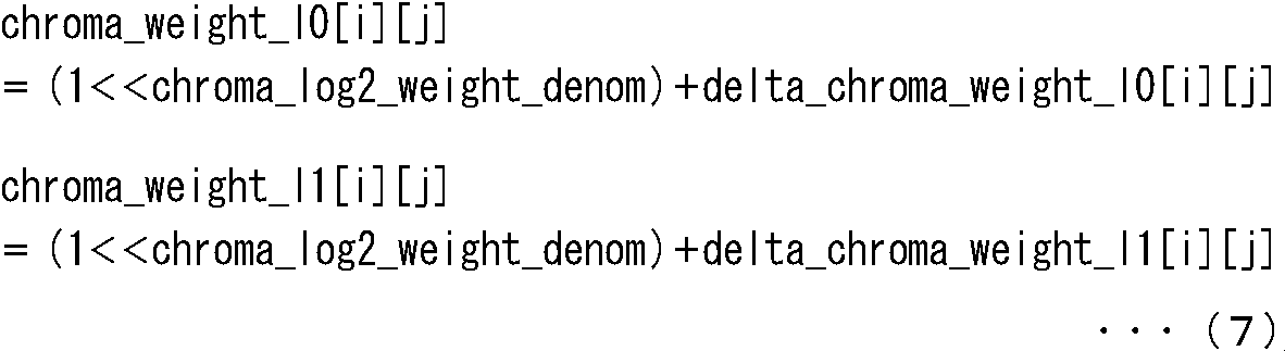

図48は、図39のエンハンスメント符号化部182の構成例を示すブロック図である。
図49は、図48の符号化部201の構成例を示すブロック図である。
図50は、図49の重みバッファ222と重み設定部223の構成例を示すブロック図である。
エンハンスメントストリームのスライスヘッダのシンタックスは、重み付け情報を除いて、ベースストリームのスライスヘッダのシンタックスと同様であるので、重み付け情報に関する情報(pred_weight_table)のシンタックスについてのみ説明する。
図39の符号化装置180の階層符号化処理は、ベース符号化部181からエンハンスメント符号化部182に供給される情報が、重み付け情報、フラグ(weighted_pred_flag)、およびフラグ(weighted_bipred_flag)である点、および、図24のステップS2のエンハンスメントストリーム生成処理を除いて図24の階層符号化処理と同様であるので、エンハンスメントストリーム生成処理についてのみ説明する。
図57は、図39の符号化装置180から伝送される全階層の符号化ストリームを復号する、本技術を適用した復号装置の第2実施の形態の構成例を示すブロック図である。
図58は、図57のエンハンスメント復号部283の構成例を示すブロック図である。
図59は、図58の復号部302の構成例を示すブロック図である。
図60は、図59の重みバッファ321と重み設定部322の構成例を示すブロック図である。
図61は、図57の復号装置280の階層復号処理を説明するフローチャートである。
(第3実施の形態の概要の説明)
図64は、本技術を適用した第3実施の形態の概要を説明する図である。
図65は、本技術を適用した符号化装置の第3実施の形態の構成例を示すブロック図である。
図66は、図65のエンハンスメント符号化部411の構成例を示すブロック図である。
図67は、図66の符号化部432の構成例を示すブロック図である。
図68は、図66の設定部431により設定されるSPSのシンタックスの例を示す図である。
図69は、エンハンスメントストリームのスライスヘッダのシンタックスの例を示す図である。
図70は、符号化装置400における効果を説明する図である。
図71は、図65の符号化装置400の階層符号化処理を説明するフローチャートである。
図74は、図65の符号化装置400から伝送される全階層の符号化ストリームを復号する、本開示を適用した復号装置の第3実施の形態の構成例を示すブロック図である。
図75は、図74のエンハンスメント復号部471の構成例を示すブロック図である。
図76は、図75の復号部491の構成例を示すブロック図である。
図74の復号装置470の階層復号処理は、図33のステップS106のエンハンスメント画像生成処理を除いて図33の階層復号処理と同様である。従って、以下では、エンハンスメント画像生成処理についてのみ説明する。
図80は、別コピーフラグ設定時に図66の設定部431により設定されるSPSのシンタックスの例を示す図である。
図81は、別コピーフラグ設定時のエンハンスメントストリームのスライスヘッダのシンタックスの例を示す図である。
別コピーフラグ設定時の階層符号化処理は、SPS設定処理とコピーフラグ設定処理を除いて、図71の階層符号化処理と同様である。従って、以下では、SPS設定処理とコピーフラグ設定処理についてのみ説明する。
別コピーフラグ設定時の階層復号処理は、SPS抽出処理と生成処理を除いて、共通コピーフラグ設定時の階層復号処理と同様である。従って、以下では、SPS抽出処理と生成処理についてのみ説明する。
図86は、第3の実施の形態におけるVPSの拡張部(vps_extension)のシンタックスの例を示す図である。
図87は、設定モード使用時に図66の設定部431により設定されるSPSのシンタックスの例を示す図である。
図88は、設定モード使用時のエンハンスメントストリームのスライスヘッダのシンタックスの例を示す図である。
設定モード使用時の階層符号化処理は、SPS設定処理とコピーフラグ設定処理を除いて、図71の階層符号化処理と同様である。従って、以下では、SPS設定処理とコピーフラグ設定処理についてのみ説明する。
設定モード使用時の階層復号処理は、SPS抽出処理と生成処理を除いて、共通コピーフラグ設定時の階層復号処理と同様である。従って、以下では、SPS抽出処理と生成処理についてのみ説明する。
図93は、符号化方式に基づく共通コピーフラグ設定時に図66の設定部431により設定されるSPSのシンタックスの例を示す図である。
符号化方式に基づく共通コピーフラグ設定時の階層符号化処理は、SPS設定処理とコピーフラグ設定処理を除いて、図71の階層符号化処理と同様である。
符号化方式に基づく共通コピーフラグ設定時の階層復号処理は、SPS抽出処理と生成処理を除いて、共通コピーフラグ設定時の階層復号処理と同様である。
(符号化装置の第4実施の形態の構成例)
図94は、本技術を適用した符号化装置の第4実施の形態の構成例を示すブロック図である。
図95は、図94のエンハンスメント符号化部531の構成例を示すブロック図である。
図96は、図95の符号化部552の構成例を示すブロック図である。
図97は、図95の設定部551により設定されるSPSのシンタックスの例を示す図である。
図98は、エンハンスメントストリームのスライスヘッダのシンタックスの例を示す図である。
図99は、一部RPSコピーフラグ用のRPSのシンタックスの例を示す図である。
図94の符号化装置530の階層符号化処理は、SPS設定処理とコピーフラグ設定処理を除いて、図71の階層符号化処理と同様である。従って、以下では、SPS設定処理とコピーフラグ設定処理についてのみ説明する。
図102は、図94の符号化装置530から伝送される全階層の符号化ストリームを復号する、本開示を適用した復号装置の第4実施の形態の構成例を示すブロック図である。
図103は、図102のエンハンスメント復号部591の構成例を示すブロック図である。
図104は、図103の復号部611の構成例を示すブロック図である。
図102の復号装置590の階層復号処理は、SPS抽出処理と生成処理を除いて復号装置470の階層復号処理と同様である。従って、以下では、SPS抽出処理と生成処理についてのみ説明する。
図107は、共通RPS設定時のRPSのシンタックスの例を示す図である。
共通RPS設定時の階層符号化処理は、SPS設定処理とコピーフラグ設定処理を除いて、図71の階層符号化処理と同様である。従って、以下では、SPS設定処理とコピーフラグ設定処理についてのみ説明する。
共通RPS設定時の階層復号処理は、SPS抽出処理と生成処理を除いて、復号装置470の階層復号処理と同様である。従って、以下では、SPS抽出処理と生成処理についてのみ説明する。
上述した一連の処理は、多視点画像符号化・多視点画像復号に適用することができる。図111は、多視点画像符号化方式の一例を示す。
(1)base-view:
(1-1) Dqp(base view)=Current_CU_QP(base view)-LCU_QP(base view)
(1-2) dQP(base view)=Current_CU_QP(base view)-Previsous_CU_QP(base view)
(1-3) dQP(base view)=Current_CU_QP(base view)-Slice_QP(base view)
(2)non-base-view:
(2-1) dQP(non-base view)=Current_CU_QP(non-base view)-LCU_QP(non-base view)
(2-2) dQP(non-base view)=CurrentQP(non-base view)-PrevisousQP(non-base view)
(2-3) dQP(non-base view)=Current_CU_QP(non-base view)-Slice_QP(non-base view)
(3)base-view/ non-base view:
(3-1) dQP(inter-view)=Slice_QP(base view)-Slice_QP(non-base view)
(3-2) dQP(inter-view)=LCU_QP(base view)-LCU_QP(non-base view)
(4)non-base view / non-base view :
(4-1) dQP(inter-view)=Slice_QP(non-base view i)-Slice_QP(non-base view j)
(4-2) dQP(inter-view)=LCU_QP(non-base view i)-LCU_QP(non-base view j)
図112は、Scalable機能による符号化の他の例を示す。
(1)base-layer:
(1-1)dQP(base layer)=Current_CU_QP(base layer)-LCU_QP(base layer)
(1-2)dQP(base layer)=Current_CU_QP(base layer)-Previsous_CU_QP(base layer)
(1-3)dQP(base layer)=Current_CU_QP(base layer)-Slice_QP(base layer)
(2)non-base-layer:
(2-1)dQP(non-base layer)=Current_CU_QP(non-base layer)-LCU_QP(non-base layer)
(2-2)dQP(non-base layer)=CurrentQP(non-base layer)-PrevisousQP(non-base layer)
(2-3)dQP(non-base layer)=Current_CU_QP(non-base layer)-Slice_QP(non-base layer)
(3)base-layer/ non-base layer:
(3-1)dQP(inter-layer)=Slice_QP(base layer)-Slice_QP(non-base layer)
(3-2)dQP(inter-layer)=LCU_QP(base layer)-LCU_QP(non-base layer)
(4)non-base layer / non-base layer :
(4-1)dQP(inter-layer)=Slice_QP(non-base layer i)-Slice_QP(non-base layer j)
(4-2)dQP(inter-layer)=LCU_QP(non-base layer i)-LCU_QP(non-base layer j)
(本技術を適用したコンピュータの説明)
上述した一連の処理は、ハードウエアにより実行することもできるし、ソフトウエアにより実行することもできる。一連の処理をソフトウエアにより実行する場合には、そのソフトウエアを構成するプログラムが、コンピュータにインストールされる。ここで、コンピュータには、専用のハードウエアに組み込まれているコンピュータや、各種のプログラムをインストールすることで、各種の機能を実行することが可能な、例えば汎用のパーソナルコンピュータなどが含まれる。
(テレビジョン装置の構成例)
図114は、本技術を適用したテレビジョン装置の概略構成を例示している。テレビジョン装置900は、アンテナ901、チューナ902、デマルチプレクサ903、デコーダ904、映像信号処理部905、表示部906、音声信号処理部907、スピーカ908、外部インタフェース部909を有している。さらに、テレビジョン装置900は、制御部910、ユーザインタフェース部911等を有している。
(携帯電話機の構成例)
図115は、本技術を適用した携帯電話機の概略構成を例示している。携帯電話機920は、通信部922、音声コーデック923、カメラ部926、画像処理部927、多重分離部928、記録再生部929、表示部930、制御部931を有している。これらは、バス933を介して互いに接続されている。
(記録再生装置の構成例)
図116は、本技術を適用した記録再生装置の概略構成を例示している。記録再生装置940は、例えば受信した放送番組のオーディオデータとビデオデータを、記録媒体に記録して、その記録されたデータをユーザの指示に応じたタイミングでユーザに提供する。また、記録再生装置940は、例えば他の装置からオーディオデータやビデオデータを取得し、それらを記録媒体に記録させることもできる。さらに、記録再生装置940は、記録媒体に記録されているオーディオデータやビデオデータを復号して出力することで、モニタ装置等において画像表示や音声出力を行うことができるようにする。
(撮像装置の構成例)
図117は、本技術を適用した撮像装置の概略構成を例示している。撮像装置960は、被写体を撮像し、被写体の画像を表示部に表示させたり、それを画像データとして、記録媒体に記録する。
(第1のシステム)
次に、scalable機能による符号化であるスケーラブル符号化(階層符号化)されたスケーラブル符号化データの具体的な利用例について説明する。スケーラブル符号化は、例えば、図118に示される例のように、伝送するデータの選択のために利用される。
また、スケーラブル符号化は、例えば、図119に示される例のように、複数の通信媒体を介する伝送のために利用される。
また、スケーラブル符号化は、例えば、図120に示される例のように、符号化データの記憶に利用される。
階層構造を有する画像の第1の階層の画像を符号化する際に用いる第1の参照画像に関する情報である第1の参照画像情報と、第2の階層の画像の第2の参照画像に関する情報である第2の参照画像情報とを用いて、前記第1の参照画像情報の生成に用いる参照画像生成情報を設定する設定部と、
前記第1の階層の画像を前記第1の参照画像を用いて符号化し、符号化データを生成する符号化部と、
前記符号化部により生成された前記符号化データと、前記設定部により設定された前記参照画像生成情報を伝送する伝送部と
を備える符号化装置。
(2)
前記設定部は、前記第1の参照画像情報と前記第2の参照画像情報が同一である場合、前記参照画像生成情報として、前記第1の参照画像情報として前記第2の参照画像情報を用いることを表す情報を設定する
前記(1)に記載の符号化装置。
(3)
前記設定部は、前記第1の参照画像情報と前記第2の参照画像情報が同一ではない場合、前記参照画像生成情報として、前記第1の参照画像情報と前記第2の参照画像情報の差分と、前記第2の参照画像情報と前記差分とから前記第1の参照画像情報を予測することを表す情報とを設定する
前記(1)または(2)に記載の符号化装置。
(4)
前記伝送部は、前記第1の階層を特定する情報を伝送する
前記(1)乃至(3)のいずれかに記載の符号化装置。
(5)
前記第1の参照画像情報は、前記第1の参照画像を特定する情報であり、
前記第2の参照画像情報は、前記第2の参照画像を特定する情報である
前記(2)に記載の符号化装置。
(6)
前記設定部は、前記参照画像生成情報をSPS(Sequence Parameter Set)単位で設定する
請求項(5)に記載の符号化装置。
(7)
前記設定部は、
short termの前記第1の参照画像を特定する情報である第1の参照画像特定情報と、short termの前記第2の参照画像を特定する情報である第2の参照画像特定情報が同一である場合、short termの前記参照画像生成情報として、前記short termの第1の参照画像特定情報として前記short termの第2の参照画像特定情報を用いることを表す情報を設定し、
long termの前記第1の参照画像特定情報とlong termの前記第2の参照画像特定情報が同一である場合、long termの前記参照画像生成情報として、前記long termの第1の参照画像特定情報として前記long termの第2の参照画像特定情報を用いることを表す情報を設定する
前記(5)または(6)に記載の符号化装置。
(8)
前記設定部は、前記第1の参照画像の設定モードに基づいて、short termの前記第1の参照画像を特定する情報である第1の参照画像特定情報と、short termの前記第2の参照画像を特定する情報である第2の参照画像特定情報が同一である場合、前記参照画像生成情報として、前記第1の参照画像特定情報として前記第2の参照画像特定情報を用いることを表す情報を設定する
前記(5)または(6)に記載の符号化装置。
(9)
前記設定部は、前記第2の階層の画像の符号化方式に基づいて、前記参照画像生成情報を設定する
前記(5)乃至(8)のいずれかに記載の符号化装置。
(10)
前記設定部は、short termの前記第1の参照画像を特定する情報である第1の参照画像特定情報の全てが、short termの前記第2の参照画像を特定する情報である第2の参照画像特定情報に含まれる場合、前記参照画像生成情報として、前記short termの第1の参照画像特定情報として前記short termの第2の参照画像特定情報の一部を用いることを表す情報を設定する
前記(5)または(6)に記載の符号化装置。
(11)
前記設定部は、前記short termの第1の参照画像特定情報の全てが、前記short termの第2の参照画像特定情報に含まれる場合、前記第2の参照画像ごとに、前記short termの第2の参照画像特定情報が前記short termの第1の参照画像特定情報として用いられるかを示す使用情報を設定し、
前記伝送部は、前記設定部により設定された前記使用情報を伝送する
前記(10)に記載の符号化装置。
(12)
重み係数を含む重み付け情報を用いて前記第1の参照画像に対して重み付けを行う重み付け処理部
をさらに備え、
前記第1の参照画像情報は、前記第1の参照画像の前記重み付け情報であり、
前記第2の参照画像情報は、前記第2の参照画像の重み付け情報であり、
前記符号化部は、前記重み付け処理部により重み付けが行われた前記第1の参照画像を用いて前記第1の階層の画像を符号化する
前記(1)乃至(4)のいずれかに記載の符号化装置。
(13)
前記重み付け処理部は、前記第2の参照画像に対して重み付けが行われた場合、前記第1の参照画像に対して前記重み付けを行う
前記(12)に記載の符号化装置。
(14)
符号化装置が、
階層構造を有する画像の第1の階層の画像を符号化する際に用いる第1の参照画像に関する情報である第1の参照画像情報と、第2の階層の画像の第2の参照画像に関する情報である第2の参照画像情報とを用いて、前記第1の参照画像情報の生成に用いる参照画像生成情報を設定する設定ステップと、
前記第1の階層の画像を前記第1の参照画像を用いて符号化し、符号化データを生成する符号化ステップと、
前記符号化ステップの処理により生成された前記符号化データと、前記設定ステップの処理により設定された前記参照画像生成情報を伝送する伝送ステップと
を含む符号化方法。
(15)
階層構造を有する画像の第1の階層の画像を符号化する際に用いる第1の参照画像に関する情報である第1の参照画像情報と、第2の階層の画像の第2の参照画像に関する情報である第2の参照画像情報とを用いて生成された、前記第1の参照画像情報の生成に用いる参照画像生成情報と、前記第1の階層の画像の符号化データとを受け取る受け取り部と、
前記参照画像生成情報を用いて前記第1の参照画像情報を生成する生成部と、
前記生成部により生成された前記第1の参照画像情報に基づいて、前記第1の階層の画像の符号化データを前記第1の参照画像を用いて復号する復号部と
を備える復号装置。
(16)
前記受け取り部は、前記参照画像生成情報として、前記第1の参照画像情報として前記第2の参照画像情報を用いることを表す情報を受け取り、
前記生成部は、前記受け取り部により受け取られた前記参照画像生成情報に基づいて、前記第2の参照画像情報を前記第1の参照画像情報として生成する
前記(15)に記載の復号装置。
(17)
前記受け取り部は、前記参照画像生成情報として、前記第1の参照画像情報と前記第2の参照画像情報の差分と、前記第2の参照画像情報と前記差分とから前記第1の参照画像情報を予測することを表す情報とを受け取り、
前記生成部は、前記受け取り部により受け取られた前記情報に基づいて、前記第2の参照画像情報と前記受け取り部により受け取られた前記差分とを加算し、その結果得られる加算値を前記第1の参照画像情報として生成する
前記(15)または(16)に記載の復号装置。
(18)
前記受け取り部は、前記第1の階層を特定する情報を受け取り、
前記生成部は、前記第1の階層を特定する情報に基づいて前記第1の参照画像情報を生成する
前記(15)乃至(17)のいずれかに記載の復号装置。
(19)
前記第1の参照画像情報は、前記第1の参照画像を特定する情報であり、
前記第2の参照画像情報は、前記第2の参照画像を特定する情報である
前記(16)に記載の復号装置。
(20)
前記受け取り部は、SPS(Sequence Parameter Set)単位で設定された前記参照画像生成情報を受け取る
請求項(19)に記載の復号装置。
(21)
前記受け取り部は、short termの前記第1の参照画像を特定する情報である第1の参照画像特定情報として、short termの前記第2の参照画像を特定する情報である第2の参照画像特定情報を用いることを表すshort termの前記参照画像生成情報と、long termの前記第1の参照画像特定情報として、long termの前記第2の参照画像特定情報を用いることを表すlong termの前記参照画像生成情報とを受け取り、
前記生成部は、前記受け取り部により受け取られたshort termの前記参照画像生成情報に基づいて、前記short termの第2の参照画像特定情報を前記short termの第1の参照画像特定情報として生成し、前記受け取り部により受け取られたlong termの前記参照画像生成情報に基づいて、前記long termの第2の参照画像特定情報を前記long termの第1の参照画像特定情報として生成する
前記(19)または(20)に記載の復号装置。
(22)
前記受け取り部は、前記第1の参照画像の設定モードに基づいて設定された、short termの前記第1の参照画像を特定する情報である第1の参照画像特定情報として、short termの前記第2の参照画像を特定する情報である第2の参照画像特定情報を用いることを表す情報を、前記参照画像生成情報として受け取り、
前記生成部は、前記受け取り部により受け取られた前記参照画像生成情報に基づいて、前記short termの第2の参照画像特定情報を前記short termの第1の参照画像特定情報として生成し、前記参照画像生成情報と前記設定モードに基づいて、前記long termの第2の参照画像特定情報を前記long termの第1の参照画像特定情報として生成する
前記(19)または(20)に記載の復号装置。
(23)
前記受け取り部は、前記第2の階層の画像の符号化方式に基づいて設定された前記参照画像生成情報を受け取る
前記(19)乃至(22)のいずれかに記載の復号装置。
(24)
前記受け取り部は、short termの前記第1の参照画像を特定する情報である第1の参照画像特定情報として、short termの前記第2の参照画像を特定する情報である第2の参照画像特定情報の一部を用いることを表す情報を前記参照画像生成情報として受け取り、
前記生成部は、前記受け取り部により受け取られた前記参照画像生成情報に基づいて、前記short termの第2の参照画像特定情報の一部を前記short termの第1の参照画像特定情報として生成する
前記(19)または(20)に記載の復号装置。
(25)
前記受け取り部は、前記第2の参照画像ごとに、前記short termの第2の参照画像特定情報が前記short termの第1の参照画像特定情報として用いられるかを示す使用情報を受け取り、
前記生成部は、前記受け取り部により受け取られた前記参照画像生成情報と使用情報に基づいて、前記short termの第2の参照画像特定情報の一部を前記short termの第1の参照画像特定情報として生成する
前記(24)に記載の復号装置。
(26)
重み係数を含む重み付け情報を用いて前記第1の参照画像に対して重み付けを行う重み付け処理部
をさらに備え、
前記第1の参照画像情報は、前記第1の参照画像の前記重み付け情報であり、
前記第2の参照画像情報は、前記第2の参照画像の重み付け情報であり、
前記重み付け処理部は、前記生成部により生成された前記第1の参照画像情報を用いて前記第1の参照画像に対して重み付けを行い、
前記復号部は、前記重み付け処理部により重み付けが行われた前記第1の参照画像を用いて前記第1の階層の画像の符号化データを復号する
前記(15)乃至(18)のいずれかに記載の復号装置。
(27)
前記重み付け処理部は、前記第2の参照画像に対して重み付けが行われた場合、前記第1の参照画像に対して前記重み付けを行う
前記(26)に記載の復号装置。
(28)
復号装置が、
階層構造を有する画像の第1の階層の画像を符号化する際に用いる第1の参照画像に関する情報である第1の参照画像情報と、第2の階層の画像の第2の参照画像に関する情報である第2の参照画像情報とを用いて生成された前記第1の参照画像情報の生成に用いる参照画像生成情報と、前記第1の階層の画像の符号化データとを受け取る受け取りステップと、
前記参照画像生成情報を用いて前記第1の参照画像情報を生成する生成ステップと、
前記生成ステップの処理により生成された前記第1の参照画像情報に基づいて、前記第1の階層の画像の符号化データを前記第1の参照画像を用いて復号する復号ステップと
を含む復号方法。
Claims (16)
- 階層構造を有する画像の第1の階層の画像を符号化する際に用いる第1の参照画像に関する情報である第1の参照画像情報と、第2の階層の画像の第2の参照画像に関する情報である第2の参照画像情報とを用いて、前記第1の参照画像情報の生成に用いる参照画像生成情報を設定する設定部と、
前記第1の階層の画像を前記第1の参照画像を用いて符号化し、符号化データを生成する符号化部と、
前記符号化部により生成された前記符号化データと、前記設定部により設定された前記参照画像生成情報を伝送する伝送部と
を備える符号化装置。 - 前記設定部は、前記第1の参照画像情報と前記第2の参照画像情報が同一である場合、前記参照画像生成情報として、前記第1の参照画像情報として前記第2の参照画像情報を用いることを表す情報を設定する
請求項1に記載の符号化装置。 - 前記設定部は、前記第1の参照画像情報と前記第2の参照画像情報が同一ではない場合、前記参照画像生成情報として、前記第1の参照画像情報と前記第2の参照画像情報の差分と、前記第2の参照画像情報と前記差分とから前記第1の参照画像情報を予測することを表す情報とを設定する
請求項1に記載の符号化装置。 - 前記伝送部は、前記第1の階層を特定する情報を伝送する
請求項1に記載の符号化装置。 - 前記第1の参照画像情報は、前記第1の参照画像を特定する情報であり、
前記第2の参照画像情報は、前記第2の参照画像を特定する情報である
請求項1に記載の符号化装置。 - 重み係数を含む重み付け情報を用いて前記第1の参照画像に対して重み付けを行う重み付け処理部
をさらに備え、
前記第1の参照画像情報は、前記第1の参照画像の前記重み付け情報であり、
前記第2の参照画像情報は、前記第2の参照画像の重み付け情報であり、
前記符号化部は、前記重み付け処理部により重み付けが行われた前記第1の参照画像を用いて前記第1の階層の画像を符号化する
請求項1に記載の符号化装置。 - 前記重み付け処理部は、前記第2の参照画像に対して重み付けが行われた場合、前記第1の参照画像に対して前記重み付けを行う
請求項6に記載の符号化装置。 - 符号化装置が、
階層構造を有する画像の第1の階層の画像を符号化する際に用いる第1の参照画像に関する情報である第1の参照画像情報と、第2の階層の画像の第2の参照画像に関する情報である第2の参照画像情報とを用いて、前記第1の参照画像情報の生成に用いる参照画像生成情報を設定する設定ステップと、
前記第1の階層の画像を前記第1の参照画像を用いて符号化し、符号化データを生成する符号化ステップと、
前記符号化ステップの処理により生成された前記符号化データと、前記設定ステップの処理により設定された前記参照画像生成情報を伝送する伝送ステップと
を含む符号化方法。 - 階層構造を有する画像の第1の階層の画像を符号化する際に用いる第1の参照画像に関する情報である第1の参照画像情報と、第2の階層の画像の第2の参照画像に関する情報である第2の参照画像情報とを用いて生成された、前記第1の参照画像情報の生成に用いる参照画像生成情報と、前記第1の階層の画像の符号化データとを受け取る受け取り部と、
前記参照画像生成情報を用いて前記第1の参照画像情報を生成する生成部と、
前記生成部により生成された前記第1の参照画像情報に基づいて、前記第1の階層の画像の符号化データを前記第1の参照画像を用いて復号する復号部と
を備える復号装置。 - 前記受け取り部は、前記参照画像生成情報として、前記第1の参照画像情報として前記第2の参照画像情報を用いることを表す情報を受け取り、
前記生成部は、前記受け取り部により受け取られた前記参照画像生成情報に基づいて、前記第2の参照画像情報を前記第1の参照画像情報として生成する
請求項9に記載の復号装置。 - 前記受け取り部は、前記参照画像生成情報として、前記第1の参照画像情報と前記第2の参照画像情報の差分と、前記第2の参照画像情報と前記差分とから前記第1の参照画像情報を予測することを表す情報とを受け取り、
前記生成部は、前記受け取り部により受け取られた前記情報に基づいて、前記第2の参照画像情報と前記受け取り部により受け取られた前記差分とを加算し、その結果得られる加算値を前記第1の参照画像情報として生成する
請求項9に記載の復号装置。 - 前記受け取り部は、前記第1の階層を特定する情報を受け取り、
前記生成部は、前記受け取り部により受け取られた前記第1の階層を特定する情報に基づいて前記第1の参照画像情報を生成する
請求項9に記載の復号装置。 - 前記第1の参照画像情報は、前記第1の参照画像を特定する情報であり、
前記第2の参照画像情報は、前記第2の参照画像を特定する情報である
請求項9に記載の復号装置。 - 重み係数を含む重み付け情報を用いて前記第1の参照画像に対して重み付けを行う重み付け処理部
をさらに備え、
前記第1の参照画像情報は、前記第1の参照画像の前記重み付け情報であり、
前記第2の参照画像情報は、前記第2の参照画像の重み付け情報であり、
前記重み付け処理部は、前記生成部により生成された前記第1の参照画像情報を用いて前記第1の参照画像に対して重み付けを行い、
前記復号部は、前記重み付け処理部により重み付けが行われた前記第1の参照画像を用いて前記第1の階層の画像の符号化データを復号する
請求項9に記載の復号装置。 - 前記重み付け処理部は、前記第2の参照画像に対して重み付けが行われた場合、前記第1の参照画像に対して前記重み付けを行う
請求項14に記載の復号装置。 - 復号装置が、
階層構造を有する画像の第1の階層の画像を符号化する際に用いる第1の参照画像に関する情報である第1の参照画像情報と、第2の階層の画像の第2の参照画像に関する情報である第2の参照画像情報とを用いて生成された前記第1の参照画像情報の生成に用いる参照画像生成情報と、前記第1の階層の画像の符号化データとを受け取る受け取りステップと、
前記参照画像生成情報を用いて前記第1の参照画像情報を生成する生成ステップと、
前記生成ステップの処理により生成された前記第1の参照画像情報に基づいて、前記第1の階層の画像の符号化データを前記第1の参照画像を用いて復号する復号ステップと
を含む復号方法。
Priority Applications (9)
| Application Number | Priority Date | Filing Date | Title |
|---|---|---|---|
| US14/427,844 US10085038B2 (en) | 2012-09-28 | 2013-09-20 | Encoding device, encoding method, decoding device, and decoding method |
| MX2015003435A MX345239B (es) | 2012-09-28 | 2013-09-20 | Dispositivo de codificación, método de codificación, dispositivo de descodificación, y método de descodificación. |
| KR1020157006851A KR20150063379A (ko) | 2012-09-28 | 2013-09-20 | 부호화 장치 및 부호화 방법, 및 복호 장치 및 복호 방법 |
| JP2014538469A JP6274108B2 (ja) | 2012-09-28 | 2013-09-20 | 符号化装置および符号化方法 |
| CN201380061119.3A CN104813663B (zh) | 2012-09-28 | 2013-09-20 | 编码设备、编码方法、解码设备和解码方法 |
| BR112015006313A BR112015006313A2 (pt) | 2012-09-28 | 2013-09-20 | dispositivos de codificação e de decodificação, e, método de decodificação |
| RU2015110063A RU2646340C2 (ru) | 2012-09-28 | 2013-09-20 | Устройство и способ кодирования, устройство и способ декодирования |
| EP13841545.0A EP2899983B1 (en) | 2012-09-28 | 2013-09-20 | Encoding device, encoding method, decoding device, and decoding method |
| US15/980,852 US10499079B2 (en) | 2012-09-28 | 2018-05-16 | Encoding device, encoding method, decoding device, and decoding method |
Applications Claiming Priority (4)
| Application Number | Priority Date | Filing Date | Title |
|---|---|---|---|
| JP2012-218303 | 2012-09-28 | ||
| JP2012218303 | 2012-09-28 | ||
| JP2013077661 | 2013-04-03 | ||
| JP2013-077661 | 2013-04-03 |
Related Child Applications (2)
| Application Number | Title | Priority Date | Filing Date |
|---|---|---|---|
| US14/427,844 A-371-Of-International US10085038B2 (en) | 2012-09-28 | 2013-09-20 | Encoding device, encoding method, decoding device, and decoding method |
| US15/980,852 Continuation US10499079B2 (en) | 2012-09-28 | 2018-05-16 | Encoding device, encoding method, decoding device, and decoding method |
Publications (1)
| Publication Number | Publication Date |
|---|---|
| WO2014050748A1 true WO2014050748A1 (ja) | 2014-04-03 |
Family
ID=50388152
Family Applications (1)
| Application Number | Title | Priority Date | Filing Date |
|---|---|---|---|
| PCT/JP2013/075518 WO2014050748A1 (ja) | 2012-09-28 | 2013-09-20 | 符号化装置および符号化方法、並びに、復号装置および復号方法 |
Country Status (9)
| Country | Link |
|---|---|
| US (2) | US10085038B2 (ja) |
| EP (1) | EP2899983B1 (ja) |
| JP (2) | JP6274108B2 (ja) |
| KR (1) | KR20150063379A (ja) |
| CN (3) | CN108521574A (ja) |
| BR (1) | BR112015006313A2 (ja) |
| MX (1) | MX345239B (ja) |
| RU (2) | RU2666305C1 (ja) |
| WO (1) | WO2014050748A1 (ja) |
Cited By (2)
| Publication number | Priority date | Publication date | Assignee | Title |
|---|---|---|---|---|
| JP2021093729A (ja) * | 2013-04-07 | 2021-06-17 | ドルビー・インターナショナル・アーベー | 映像復号方法 |
| US11553198B2 (en) | 2013-04-07 | 2023-01-10 | Dolby International Ab | Removal delay parameters for video coding |
Families Citing this family (8)
| Publication number | Priority date | Publication date | Assignee | Title |
|---|---|---|---|---|
| US9967581B2 (en) * | 2014-05-29 | 2018-05-08 | Apple Inc. | Video quality adaptation with frame rate conversion |
| JP6597041B2 (ja) * | 2015-08-18 | 2019-10-30 | 富士ゼロックス株式会社 | サーバー装置及び情報処理システム |
| CN117082237A (zh) | 2016-04-29 | 2023-11-17 | 世宗大学校产学协力团 | 用于对图像信号进行编码/解码的方法和设备 |
| KR102383107B1 (ko) * | 2016-07-05 | 2022-04-06 | 주식회사 케이티 | 비디오 신호 처리 방법 및 장치 |
| US10264263B2 (en) | 2016-07-06 | 2019-04-16 | Morpho Detection, Llc | Systems and methods for compressing image data generated by a computed tomography (CT) imaging system |
| US11729417B2 (en) * | 2018-10-02 | 2023-08-15 | Interdigital Vc Holdings, Inc. | Generalized bi-prediction and weighted prediction |
| WO2020180166A1 (ko) * | 2019-03-07 | 2020-09-10 | 디지털인사이트주식회사 | 영상 부호화/복호화 방법 및 장치 |
| KR20220049554A (ko) * | 2019-09-16 | 2022-04-21 | 엘지전자 주식회사 | 가중 예측을 이용한 영상 부호화/복호화 방법, 장치 및 비트스트림을 전송하는 방법 |
Citations (4)
| Publication number | Priority date | Publication date | Assignee | Title |
|---|---|---|---|---|
| JP2008535424A (ja) * | 2005-04-06 | 2008-08-28 | トムソン ライセンシング | エンハンスメント層ビデオ・データを符号化する方法および装置 |
| JP2009512347A (ja) * | 2005-10-12 | 2009-03-19 | トムソン ライセンシング | スケーラブルビデオ符号化及び復号における重み付け予測方法及び装置 |
| JP2009522888A (ja) * | 2006-01-10 | 2009-06-11 | トムソン ライセンシング | スケーラブル・ビデオ用参照ピクチャ・リストを構築するための方法及び装置 |
| JP2010517343A (ja) * | 2007-01-18 | 2010-05-20 | フラウンホッファー−ゲゼルシャフト ツァ フェルダールング デァ アンゲヴァンテン フォアシュンク エー.ファオ | 品質スケーラブル・ビデオ・データ・ストリーム |
Family Cites Families (25)
| Publication number | Priority date | Publication date | Assignee | Title |
|---|---|---|---|---|
| JP2005506815A (ja) * | 2001-10-26 | 2005-03-03 | コーニンクレッカ フィリップス エレクトロニクス エヌ ヴィ | 空間拡張可能圧縮のための方法及び装置 |
| EP1830577A1 (en) * | 2002-01-18 | 2007-09-05 | Kabushiki Kaisha Toshiba | Video decoding method and apparatus |
| KR100931915B1 (ko) * | 2002-01-23 | 2009-12-15 | 노키아 코포레이션 | 비디오 코딩시 이미지 프레임들의 그루핑 |
| KR100693669B1 (ko) * | 2003-03-03 | 2007-03-09 | 엘지전자 주식회사 | 피일드 매크로 블록의 레퍼런스 픽쳐 결정 방법 |
| WO2006112272A1 (ja) * | 2005-04-13 | 2006-10-26 | Ntt Docomo, Inc. | 動画像符号化装置、動画像復号装置、動画像符号化方法、動画像復号方法、動画像符号化プログラム、および動画像復号プログラム |
| EP1915870B1 (en) * | 2005-07-21 | 2017-03-08 | Thomson Licensing | Method and apparatus for weighted prediction for scalable video coding |
| RU2368095C1 (ru) * | 2005-07-22 | 2009-09-20 | Мицубиси Электрик Корпорейшн | Кодер изображения и декодер изображения, способ кодирования изображения и способ декодирования изображения, программа кодирования изображения и программа декодирования изображения и компьютерно-считываемый носитель записи, на котором записана программа кодирования изображения, и компьютерно-считываемый носитель записи, на котором записана программа декодирования изображения |
| KR20070038396A (ko) * | 2005-10-05 | 2007-04-10 | 엘지전자 주식회사 | 영상 신호의 인코딩 및 디코딩 방법 |
| US7956930B2 (en) * | 2006-01-06 | 2011-06-07 | Microsoft Corporation | Resampling and picture resizing operations for multi-resolution video coding and decoding |
| WO2008083296A2 (en) * | 2006-12-28 | 2008-07-10 | Vidyo, Inc. | System and method for in-loop deblocking in scalable video coding |
| JP5026092B2 (ja) * | 2007-01-12 | 2012-09-12 | 三菱電機株式会社 | 動画像復号装置および動画像復号方法 |
| EP2051527A1 (en) * | 2007-10-15 | 2009-04-22 | Thomson Licensing | Enhancement layer residual prediction for bit depth scalability using hierarchical LUTs |
| CA2702525C (en) * | 2007-10-25 | 2014-07-15 | Nippon Telegraph And Telephone Corporation | Video scalable encoding method and decoding method and apparatuses therefor |
| TWI468020B (zh) * | 2009-02-19 | 2015-01-01 | Sony Corp | Image processing apparatus and method |
| JP2011015262A (ja) * | 2009-07-03 | 2011-01-20 | Panasonic Corp | 画像復号化装置 |
| KR20110065089A (ko) * | 2009-12-09 | 2011-06-15 | 삼성전자주식회사 | 영상의 부호화 방법 및 장치, 그 복호화 방법 및 장치 |
| JP5563346B2 (ja) * | 2010-03-29 | 2014-07-30 | パナソニック株式会社 | 送電装置及びそれに用いられる波形モニタ回路 |
| CN102186084B (zh) * | 2011-06-07 | 2013-07-31 | 东莞电子科技大学电子信息工程研究院 | 一种可伸缩视频编码svc的空间增强层码率控制实现方法 |
| ITMI20111388A1 (it) * | 2011-07-26 | 2013-01-27 | Presezzi Extrusion S P A | Dispositivo perfezionato applicabile a presse per l'estrusione di metalli atto a consentire una rapida sostituzione del tacco e/o dell'asta applicati a tali presse. |
| US8863391B2 (en) * | 2011-07-27 | 2014-10-21 | Progressive International Corporation | Egg slicer |
| US11445172B2 (en) * | 2012-01-31 | 2022-09-13 | Vid Scale, Inc. | Reference picture set (RPS) signaling for scalable high efficiency video coding (HEVC) |
| US9392274B2 (en) * | 2012-03-22 | 2016-07-12 | Qualcomm Incorporated | Inter layer texture prediction for video coding |
| TW201408071A (zh) * | 2012-04-09 | 2014-02-16 | Vid Scale Inc | 視訊編碼加權預測參數傳訊 |
| US9516308B2 (en) * | 2012-04-27 | 2016-12-06 | Qualcomm Incorporated | Parameter set updates in video coding |
| EP2824287B1 (en) * | 2013-07-08 | 2020-05-13 | Ansaldo Energia IP UK Limited | Pressure casing of a turbomachine |
-
2013
- 2013-09-20 RU RU2018104709A patent/RU2666305C1/ru not_active IP Right Cessation
- 2013-09-20 CN CN201810364091.5A patent/CN108521574A/zh active Pending
- 2013-09-20 JP JP2014538469A patent/JP6274108B2/ja not_active Expired - Fee Related
- 2013-09-20 MX MX2015003435A patent/MX345239B/es active IP Right Grant
- 2013-09-20 KR KR1020157006851A patent/KR20150063379A/ko not_active Application Discontinuation
- 2013-09-20 EP EP13841545.0A patent/EP2899983B1/en not_active Not-in-force
- 2013-09-20 WO PCT/JP2013/075518 patent/WO2014050748A1/ja active Application Filing
- 2013-09-20 CN CN201380061119.3A patent/CN104813663B/zh not_active Expired - Fee Related
- 2013-09-20 US US14/427,844 patent/US10085038B2/en active Active
- 2013-09-20 BR BR112015006313A patent/BR112015006313A2/pt not_active Application Discontinuation
- 2013-09-20 CN CN201810364098.7A patent/CN108337524A/zh active Pending
- 2013-09-20 RU RU2015110063A patent/RU2646340C2/ru not_active IP Right Cessation
-
2018
- 2018-01-11 JP JP2018002625A patent/JP6432809B2/ja not_active Expired - Fee Related
- 2018-05-16 US US15/980,852 patent/US10499079B2/en active Active
Patent Citations (4)
| Publication number | Priority date | Publication date | Assignee | Title |
|---|---|---|---|---|
| JP2008535424A (ja) * | 2005-04-06 | 2008-08-28 | トムソン ライセンシング | エンハンスメント層ビデオ・データを符号化する方法および装置 |
| JP2009512347A (ja) * | 2005-10-12 | 2009-03-19 | トムソン ライセンシング | スケーラブルビデオ符号化及び復号における重み付け予測方法及び装置 |
| JP2009522888A (ja) * | 2006-01-10 | 2009-06-11 | トムソン ライセンシング | スケーラブル・ビデオ用参照ピクチャ・リストを構築するための方法及び装置 |
| JP2010517343A (ja) * | 2007-01-18 | 2010-05-20 | フラウンホッファー−ゲゼルシャフト ツァ フェルダールング デァ アンゲヴァンテン フォアシュンク エー.ファオ | 品質スケーラブル・ビデオ・データ・ストリーム |
Non-Patent Citations (2)
| Title |
|---|
| BENJAMIN BROSS; WOO-JIN HAN; JENS-RAINER OHM; GARY J. SULLIVAN; THOMAS WIEGAND: "High efficiency video coding (HEVC) text specification draft 8", JCTVC-I1003 _D7, 2012, pages 7.11 - 7.20 |
| DO-KYOUNG KWON; MADHUKAR BUDAGAVI; MINHUA ZHOU: "Inter-layer slice header syntax element prediction in SHVC", JCTVC-L0231, 2013, pages 1.14 - 1.23 |
Cited By (4)
| Publication number | Priority date | Publication date | Assignee | Title |
|---|---|---|---|---|
| JP2021093729A (ja) * | 2013-04-07 | 2021-06-17 | ドルビー・インターナショナル・アーベー | 映像復号方法 |
| JP7047146B2 (ja) | 2013-04-07 | 2022-04-04 | ドルビー・インターナショナル・アーベー | 映像復号方法 |
| US11553198B2 (en) | 2013-04-07 | 2023-01-10 | Dolby International Ab | Removal delay parameters for video coding |
| US11653011B2 (en) | 2013-04-07 | 2023-05-16 | Dolby International Ab | Decoded picture buffer removal |
Also Published As
| Publication number | Publication date |
|---|---|
| CN108521574A (zh) | 2018-09-11 |
| JP6432809B2 (ja) | 2018-12-05 |
| MX345239B (es) | 2017-01-23 |
| EP2899983A4 (en) | 2016-06-08 |
| EP2899983B1 (en) | 2018-11-21 |
| JP2018085757A (ja) | 2018-05-31 |
| RU2015110063A (ru) | 2016-10-10 |
| US20180270503A1 (en) | 2018-09-20 |
| CN104813663A (zh) | 2015-07-29 |
| KR20150063379A (ko) | 2015-06-09 |
| US10085038B2 (en) | 2018-09-25 |
| US10499079B2 (en) | 2019-12-03 |
| EP2899983A1 (en) | 2015-07-29 |
| BR112015006313A2 (pt) | 2017-07-04 |
| RU2666305C1 (ru) | 2018-09-06 |
| CN108337524A (zh) | 2018-07-27 |
| US20150222921A1 (en) | 2015-08-06 |
| RU2646340C2 (ru) | 2018-03-02 |
| JPWO2014050748A1 (ja) | 2016-08-22 |
| JP6274108B2 (ja) | 2018-02-07 |
| MX2015003435A (es) | 2015-06-22 |
| CN104813663B (zh) | 2018-05-22 |
Similar Documents
| Publication | Publication Date | Title |
|---|---|---|
| JP6432809B2 (ja) | 復号装置および復号方法 | |
| JP6580648B2 (ja) | 画像処理装置および記録媒体 | |
| AU2012227626B2 (en) | Image processing device and method | |
| JP5954587B2 (ja) | 画像処理装置および方法 | |
| WO2013031315A1 (ja) | 画像処理装置及び画像処理方法 | |
| US20230247217A1 (en) | Image processing apparatus and method | |
| JPWO2014002896A1 (ja) | 符号化装置および符号化方法、復号装置および復号方法 | |
| JP6316346B2 (ja) | 画像処理装置、画像処理方法、プログラム及び記録媒体 | |
| JP2015005899A (ja) | 復号装置および復号方法、並びに、符号化装置および符号化方法 | |
| WO2014103774A1 (ja) | 画像処理装置および方法 | |
| WO2014103764A1 (ja) | 画像処理装置および方法 | |
| WO2012173022A1 (ja) | 画像処理装置および方法 | |
| WO2014141899A1 (ja) | 画像処理装置および方法 | |
| WO2014050732A1 (ja) | 符号化装置および符号化方法、並びに、復号装置および復号方法 | |
| JPWO2014002900A1 (ja) | 画像処理装置および画像処理方法 | |
| WO2013015118A1 (ja) | 画像処理装置および方法 | |
| WO2014156705A1 (ja) | 復号装置および復号方法、並びに、符号化装置および符号化方法 | |
| WO2014203762A1 (ja) | 復号装置および復号方法、並びに、符号化装置および符号化方法 | |
| JP2015089078A (ja) | 画像処理装置および方法 | |
| WO2014097937A1 (ja) | 画像処理装置および画像処理方法 |
Legal Events
| Date | Code | Title | Description |
|---|---|---|---|
| 121 | Ep: the epo has been informed by wipo that ep was designated in this application |
Ref document number: 13841545 Country of ref document: EP Kind code of ref document: A1 |
|
| ENP | Entry into the national phase |
Ref document number: 2014538469 Country of ref document: JP Kind code of ref document: A |
|
| WWE | Wipo information: entry into national phase |
Ref document number: 14427844 Country of ref document: US |
|
| ENP | Entry into the national phase |
Ref document number: 20157006851 Country of ref document: KR Kind code of ref document: A |
|
| WWE | Wipo information: entry into national phase |
Ref document number: MX/A/2015/003435 Country of ref document: MX |
|
| ENP | Entry into the national phase |
Ref document number: 2015110063 Country of ref document: RU Kind code of ref document: A |
|
| NENP | Non-entry into the national phase |
Ref country code: DE |
|
| REG | Reference to national code |
Ref country code: BR Ref legal event code: B01A Ref document number: 112015006313 Country of ref document: BR |
|
| ENP | Entry into the national phase |
Ref document number: 112015006313 Country of ref document: BR Kind code of ref document: A2 Effective date: 20150320 |