WO2014050677A1 - 画像処理装置および方法 - Google Patents
画像処理装置および方法 Download PDFInfo
- Publication number
- WO2014050677A1 WO2014050677A1 PCT/JP2013/075228 JP2013075228W WO2014050677A1 WO 2014050677 A1 WO2014050677 A1 WO 2014050677A1 JP 2013075228 W JP2013075228 W JP 2013075228W WO 2014050677 A1 WO2014050677 A1 WO 2014050677A1
- Authority
- WO
- WIPO (PCT)
- Prior art keywords
- layer
- inter
- prediction
- unit
- image
- Prior art date
Links
Images


Classifications
-
- H—ELECTRICITY
- H04—ELECTRIC COMMUNICATION TECHNIQUE
- H04N—PICTORIAL COMMUNICATION, e.g. TELEVISION
- H04N19/00—Methods or arrangements for coding, decoding, compressing or decompressing digital video signals
- H04N19/50—Methods or arrangements for coding, decoding, compressing or decompressing digital video signals using predictive coding
- H04N19/503—Methods or arrangements for coding, decoding, compressing or decompressing digital video signals using predictive coding involving temporal prediction
-
- H—ELECTRICITY
- H04—ELECTRIC COMMUNICATION TECHNIQUE
- H04N—PICTORIAL COMMUNICATION, e.g. TELEVISION
- H04N19/00—Methods or arrangements for coding, decoding, compressing or decompressing digital video signals
- H04N19/30—Methods or arrangements for coding, decoding, compressing or decompressing digital video signals using hierarchical techniques, e.g. scalability
- H04N19/34—Scalability techniques involving progressive bit-plane based encoding of the enhancement layer, e.g. fine granular scalability [FGS]
-
- H—ELECTRICITY
- H04—ELECTRIC COMMUNICATION TECHNIQUE
- H04N—PICTORIAL COMMUNICATION, e.g. TELEVISION
- H04N19/00—Methods or arrangements for coding, decoding, compressing or decompressing digital video signals
- H04N19/10—Methods or arrangements for coding, decoding, compressing or decompressing digital video signals using adaptive coding
- H04N19/102—Methods or arrangements for coding, decoding, compressing or decompressing digital video signals using adaptive coding characterised by the element, parameter or selection affected or controlled by the adaptive coding
- H04N19/103—Selection of coding mode or of prediction mode
- H04N19/105—Selection of the reference unit for prediction within a chosen coding or prediction mode, e.g. adaptive choice of position and number of pixels used for prediction
-
- H—ELECTRICITY
- H04—ELECTRIC COMMUNICATION TECHNIQUE
- H04N—PICTORIAL COMMUNICATION, e.g. TELEVISION
- H04N19/00—Methods or arrangements for coding, decoding, compressing or decompressing digital video signals
- H04N19/10—Methods or arrangements for coding, decoding, compressing or decompressing digital video signals using adaptive coding
- H04N19/134—Methods or arrangements for coding, decoding, compressing or decompressing digital video signals using adaptive coding characterised by the element, parameter or criterion affecting or controlling the adaptive coding
- H04N19/146—Data rate or code amount at the encoder output
- H04N19/147—Data rate or code amount at the encoder output according to rate distortion criteria
-
- H—ELECTRICITY
- H04—ELECTRIC COMMUNICATION TECHNIQUE
- H04N—PICTORIAL COMMUNICATION, e.g. TELEVISION
- H04N19/00—Methods or arrangements for coding, decoding, compressing or decompressing digital video signals
- H04N19/10—Methods or arrangements for coding, decoding, compressing or decompressing digital video signals using adaptive coding
- H04N19/134—Methods or arrangements for coding, decoding, compressing or decompressing digital video signals using adaptive coding characterised by the element, parameter or criterion affecting or controlling the adaptive coding
- H04N19/157—Assigned coding mode, i.e. the coding mode being predefined or preselected to be further used for selection of another element or parameter
- H04N19/159—Prediction type, e.g. intra-frame, inter-frame or bidirectional frame prediction
-
- H—ELECTRICITY
- H04—ELECTRIC COMMUNICATION TECHNIQUE
- H04N—PICTORIAL COMMUNICATION, e.g. TELEVISION
- H04N19/00—Methods or arrangements for coding, decoding, compressing or decompressing digital video signals
- H04N19/10—Methods or arrangements for coding, decoding, compressing or decompressing digital video signals using adaptive coding
- H04N19/169—Methods or arrangements for coding, decoding, compressing or decompressing digital video signals using adaptive coding characterised by the coding unit, i.e. the structural portion or semantic portion of the video signal being the object or the subject of the adaptive coding
- H04N19/17—Methods or arrangements for coding, decoding, compressing or decompressing digital video signals using adaptive coding characterised by the coding unit, i.e. the structural portion or semantic portion of the video signal being the object or the subject of the adaptive coding the unit being an image region, e.g. an object
- H04N19/172—Methods or arrangements for coding, decoding, compressing or decompressing digital video signals using adaptive coding characterised by the coding unit, i.e. the structural portion or semantic portion of the video signal being the object or the subject of the adaptive coding the unit being an image region, e.g. an object the region being a picture, frame or field
-
- H—ELECTRICITY
- H04—ELECTRIC COMMUNICATION TECHNIQUE
- H04N—PICTORIAL COMMUNICATION, e.g. TELEVISION
- H04N19/00—Methods or arrangements for coding, decoding, compressing or decompressing digital video signals
- H04N19/10—Methods or arrangements for coding, decoding, compressing or decompressing digital video signals using adaptive coding
- H04N19/169—Methods or arrangements for coding, decoding, compressing or decompressing digital video signals using adaptive coding characterised by the coding unit, i.e. the structural portion or semantic portion of the video signal being the object or the subject of the adaptive coding
- H04N19/187—Methods or arrangements for coding, decoding, compressing or decompressing digital video signals using adaptive coding characterised by the coding unit, i.e. the structural portion or semantic portion of the video signal being the object or the subject of the adaptive coding the unit being a scalable video layer
-
- H—ELECTRICITY
- H04—ELECTRIC COMMUNICATION TECHNIQUE
- H04N—PICTORIAL COMMUNICATION, e.g. TELEVISION
- H04N19/00—Methods or arrangements for coding, decoding, compressing or decompressing digital video signals
- H04N19/30—Methods or arrangements for coding, decoding, compressing or decompressing digital video signals using hierarchical techniques, e.g. scalability
- H04N19/31—Methods or arrangements for coding, decoding, compressing or decompressing digital video signals using hierarchical techniques, e.g. scalability in the temporal domain
-
- H—ELECTRICITY
- H04—ELECTRIC COMMUNICATION TECHNIQUE
- H04N—PICTORIAL COMMUNICATION, e.g. TELEVISION
- H04N19/00—Methods or arrangements for coding, decoding, compressing or decompressing digital video signals
- H04N19/44—Decoders specially adapted therefor, e.g. video decoders which are asymmetric with respect to the encoder
-
- H—ELECTRICITY
- H04—ELECTRIC COMMUNICATION TECHNIQUE
- H04N—PICTORIAL COMMUNICATION, e.g. TELEVISION
- H04N19/00—Methods or arrangements for coding, decoding, compressing or decompressing digital video signals
- H04N19/50—Methods or arrangements for coding, decoding, compressing or decompressing digital video signals using predictive coding
- H04N19/503—Methods or arrangements for coding, decoding, compressing or decompressing digital video signals using predictive coding involving temporal prediction
- H04N19/51—Motion estimation or motion compensation
- H04N19/513—Processing of motion vectors
- H04N19/517—Processing of motion vectors by encoding
- H04N19/52—Processing of motion vectors by encoding by predictive encoding
-
- H—ELECTRICITY
- H04—ELECTRIC COMMUNICATION TECHNIQUE
- H04N—PICTORIAL COMMUNICATION, e.g. TELEVISION
- H04N19/00—Methods or arrangements for coding, decoding, compressing or decompressing digital video signals
- H04N19/70—Methods or arrangements for coding, decoding, compressing or decompressing digital video signals characterised by syntax aspects related to video coding, e.g. related to compression standards
Definitions
- the present disclosure relates to an image processing apparatus and method, and more particularly, to an image processing apparatus and method capable of suppressing a reduction in encoding efficiency.
- MPEG2 (ISO / IEC 13818-2) is defined as a general-purpose image encoding system, and is a standard that covers both interlaced scanning images and progressive scanning images, as well as standard resolution images and high-definition images.
- MPEG2 is currently widely used in a wide range of applications for professional and consumer applications.
- a code amount (bit rate) of 4 to 8 Mbps is assigned to an interlaced scanned image having a standard resolution of 720 ⁇ 480 pixels.
- a high resolution interlaced scanned image having 1920 ⁇ 1088 pixels is assigned a code amount (bit rate) of 18 to 22 Mbps.
- bit rate code amount
- MPEG2 was mainly intended for high-quality encoding suitable for broadcasting, but did not support encoding methods with a lower code amount (bit rate) than MPEG1, that is, a higher compression rate.
- bit rate code amount
- MPEG4 encoding system has been standardized accordingly.
- the standard was approved as an international standard in December 1998 as ISO / IEC 14496-2.
- H.26L International Telecommunication Union Telecommunication Standardization Sector
- Q6 / 16 VCEG Video Coding Expert Group
- H.26L is known to achieve higher encoding efficiency than the conventional encoding schemes such as MPEG2 and MPEG4, although a large amount of calculation is required for encoding and decoding.
- Joint ⁇ ⁇ ⁇ ⁇ Model of Enhanced-Compression Video Coding has been implemented based on this H.26L and incorporating functions not supported by H.26L to achieve higher coding efficiency. It was broken.
- AVC Advanced Video Coding
- HEVC High Efficiency Video Video Coding
- JCTVC Joint Collaboration Collaboration Team Video Coding
- ISO / IEC ISO / IEC
- the standardization of the encoding method called is being advanced.
- CommitteeCommitdraft which is the first draft version specification, was issued in February 2012 (see Non-Patent Document 1, for example).
- the conventional image encoding methods such as MPEG-2 and AVC have a scalability function for encoding an image by layering it into a plurality of layers.
- a mobile phone or other low-processing-capacity terminal transmits image compression information of only the base layer (base layer), and reproduces a moving image with low spatiotemporal resolution or poor image quality.
- base layer the image compression information of the enhancement layer is transmitted, and the space-time resolution is high.
- Non-Patent Document 2 it has been proposed to specify on / off of prediction processing between layers for each picture (Picture) in a NAL unit (NAL_Unit) (see, for example, Non-Patent Document 2).
- This disclosure has been made in view of such a situation, and is intended to suppress a reduction in encoding efficiency.
- One aspect of the present technology is an inter-layer control that uses sublayers to control whether encoded data obtained by encoding an image having a plurality of main layers and inter-layer prediction that is prediction between the plurality of main layers.
- a receiving unit that receives prediction control information; and the encoded data received by the receiving unit so that the inter-layer prediction is performed only on the sublayer specified by the inter-layer prediction control information received by the receiving unit.
- a decoding unit that decodes each main layer.
- the decoding unit When the current picture of the current main layer belongs to a sub-layer designated to perform the inter-layer prediction by the inter-layer prediction control information, the decoding unit performs the inter-layer prediction on the encoded data of the current picture. Can be used to decrypt.
- the inter-layer prediction control information specifies the highest sublayer that allows the inter-layer prediction, and the decoding unit belongs to a sub-layer from the lowest sub-layer to the highest sub-layer specified by the inter-layer prediction control information
- the encoded data of a picture can be decoded using the inter-layer prediction.
- the inter-layer prediction control information can be set for each main layer.
- the inter-layer prediction control information can be set as a parameter common to all main layers.
- the receiving unit as the inter-layer prediction control information, is set independently of each other, inter-layer pixel prediction control information for controlling whether to perform inter-layer pixel prediction, which is pixel prediction between the plurality of main layers, Inter-layer syntax prediction control information for controlling whether to perform inter-layer syntax prediction that is syntax prediction between a plurality of main layers, and the decoding unit receives the inter-layer pixel prediction control information received by the receiving unit.
- the inter-layer pixel prediction is performed based on the inter-layer syntax prediction control information received by the receiving unit, and the inter-layer syntax prediction is performed.
- the inter-layer pixel prediction control information controls whether to perform the inter-layer pixel prediction using the sub-layer, and the decoding unit performs the inter-layer pixel prediction only on the sub-layer specified by the inter-layer pixel prediction control information.
- the inter-layer syntax prediction control information controls, for each picture or slice, whether to perform the inter-layer syntax prediction, and the decoding unit only performs the picture or slice specified by the inter-layer syntax prediction control information.
- the inter-layer syntax prediction can be performed.
- the inter-layer pixel prediction control information may be transmitted as a null unit (nal_unit), a video parameter set (VPS (Video Parameter Set)), or an extended video parameter set (vps_extension).
- null unit null unit
- VPS Video Parameter Set
- vps_extension extended video parameter set
- the inter-layer syntax prediction control information can be transmitted as a null unit (nal_unit), a picture parameter set (PPS (Picture Parameter Set)), or a slice header (SliceHeader).
- One aspect of the present technology also uses sub-layers to control whether encoded data obtained by encoding an image having a plurality of main layers and inter-layer prediction that is prediction between the plurality of main layers are performed.
- Another aspect of the present technology is to perform the inter-layer prediction only on the sublayer specified by the inter-layer prediction control information that is controlled by using the sub-layer.
- An encoding unit that encodes each main layer of the image data, a transmission unit that transmits the encoded data obtained by encoding by the encoding unit, and the inter-layer prediction control information.
- An image processing apparatus that performs the inter-layer prediction only on the sublayer specified by the inter-layer prediction control information that is controlled by using the sub-layer.
- the encoding unit When the current picture of the current main layer belongs to a sublayer designated to perform the inter-layer prediction by the inter-layer prediction control information, the encoding unit performs the inter-layer prediction on the image data of the current picture. Can be used to encode.
- the inter-layer prediction control information specifies the highest sublayer that permits the inter-layer prediction, and the encoding unit applies sub-layers from the lowest sub-layer to the highest sub-layer specified by the inter-layer prediction control information.
- Image data of a picture to which it belongs can be encoded using the inter-layer prediction.
- the inter-layer prediction control information can be set for each main layer.
- the inter-layer prediction control information can be set as a parameter common to all main layers.
- the encoding unit sets the inter-layer based on the inter-layer pixel prediction control information that is set as the inter-layer prediction control information and controls whether to perform inter-layer pixel prediction that is pixel prediction between the plurality of main layers.
- a layer that performs pixel prediction and controls whether to perform inter-layer syntax prediction that is syntax prediction between the plurality of main layers set independently of the inter-layer pixel prediction control information as the inter-layer prediction control information
- the inter-layer syntax prediction is performed based on inter-syntax prediction control information, and the transmission unit sets the inter-layer pixel prediction control information and the inter-layer syntax prediction control information that are set independently of each other as the inter-layer prediction control information. Can be transmitted.
- the inter-layer pixel prediction control information uses the sub-layer to control whether to perform the inter-layer pixel prediction, and the encoding unit only applies the inter-layer pixel to the sub-layer specified by the inter-layer pixel prediction control information.
- the inter-layer syntax prediction control information controls whether to perform the inter-layer syntax prediction for each picture or slice, and the encoding unit includes a picture specified by the inter-layer syntax prediction control information or The inter-layer syntax prediction can be performed only for slices.
- the transmission unit may transmit the inter-layer pixel prediction control information as a null unit (nal_unit), a video parameter set (VPS (Video Parameter Set)), or an extended video parameter set (vps_extension).
- null unit null unit
- VPS Video Parameter Set
- vps_extension extended video parameter set
- the transmission unit can transmit the inter-layer syntax prediction control information as a null unit (nal_unit), a picture parameter set (PPS (Picture Parameter Set)), or a slice header (SliceHeader).
- null unit null unit
- PPS Picture Parameter Set
- slice header SliceHeader
- the inter-layer prediction is performed only for the sub-layer specified by the inter-layer prediction control information that is controlled using the sub-layer to perform inter-layer prediction that is prediction between a plurality of main layers.
- this is an image processing method for encoding each main layer of the image data and transmitting the encoded data obtained by encoding and the inter-layer prediction control information.
- inter-layer control is performed using sublayers to determine whether to perform inter-layer prediction, which is prediction between a plurality of main layers, and encoded data obtained by encoding an image having a plurality of main layers.
- the prediction control information is received, and each main layer of the received encoded data is decoded such that only the sublayer specified by the received inter-layer prediction control information is subjected to inter-layer prediction.
- whether to perform inter-layer prediction is performed by performing inter-layer prediction only on the sub-layer specified by the inter-layer prediction control information controlled using the sub-layer.
- each main layer of the image data is encoded, encoded data obtained by encoding, and inter-layer prediction control information are transmitted.
- an image can be encoded and decoded.
- a reduction in encoding efficiency can be suppressed.
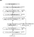
- FIG. 55 explaining the example of the flow of a prediction process.
- FIG. 55 explaining the example of the flow of a prediction process.
- FIG. 58 is a diagram subsequent to FIG. 57 illustrating an example of the sequence parameter set.
- FIG. 60 is a diagram subsequent to FIG. 59 illustrating an example of a slice header.
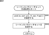
- FIG. 60 is a diagram subsequent to FIG. 60 illustrating an example of a slice header. It is a block diagram which shows the main structural examples of an image coding apparatus. It is a block diagram which shows the main structural examples of a base layer image coding part. It is a block diagram which shows the main structural examples of an enhancement layer image coding part. It is a flowchart explaining the example of the flow of an image encoding process. It is a flowchart explaining the example of the flow of a base layer encoding process. It is a flowchart explaining the example of the flow of a sequence parameter set production
- FIG. 20 is a block diagram illustrating a main configuration example of a computer. It is a block diagram which shows an example of a schematic structure of a television apparatus. It is a block diagram which shows an example of a schematic structure of a mobile telephone. It is a block diagram which shows an example of a schematic structure of a recording / reproducing apparatus. It is a block diagram which shows an example of a schematic structure of an imaging device.
- ⁇ Coding unit> In the AVC (Advanced Video Coding) method, a hierarchical structure is defined by macroblocks and sub-macroblocks. However, a macroblock of 16 pixels ⁇ 16 pixels is not optimal for a large image frame such as UHD (Ultra High Definition; 4000 pixels ⁇ 2000 pixels), which is a target of the next generation encoding method.
- UHD Ultra High Definition
- a coding unit (Coding Unit)) is defined.
- CU also called Coding Tree Block (CTB)
- CTB Coding Tree Block
- the maximum size (LCU (Largest Coding Unit)) and the minimum size (SCU (Smallest Coding Unit)) are specified.
- the LCU size is 128 and the maximum hierarchical depth is 5.
- split_flag is “1”
- the 2N ⁇ 2N size CU is divided into N ⁇ N size CUs that are one level below.
- the CU is divided into prediction units (Prediction Units (PU)) that are regions (partial regions of images in units of pictures) that are processing units of intra or inter prediction, and are regions that are processing units of orthogonal transformation It is divided into transform units (Transform Unit (TU)), which is (a partial area of an image in units of pictures).
- Prediction Units PU
- transform Unit Transform Unit
- a macro block in the AVC method corresponds to an LCU
- a block (sub block) corresponds to a CU. Then you can think.
- a motion compensation block in the AVC method can be considered to correspond to a PU.
- the size of the LCU of the highest hierarchy is generally set larger than the macro block of the AVC method, for example, 128 ⁇ 128 pixels.
- the LCU also includes a macroblock in the AVC scheme
- the CU also includes a block (sub-block) in the AVC scheme.
- “block” used in the following description indicates an arbitrary partial area in the picture, and its size, shape, characteristics, and the like are not limited. That is, the “block” includes an arbitrary area (processing unit) such as a TU, PU, SCU, CU, LCU, sub-block, macroblock, or slice. Of course, other partial areas (processing units) are also included. When it is necessary to limit the size, processing unit, etc., it will be described as appropriate.
- CTU Coding Tree Unit
- CTB Coding Tree Block
- CU Coding ⁇ Unit
- CB Coding ⁇ ⁇ ⁇ ⁇ Block
- JM Job Model
- JM JM
- High Complexity Mode Low Complexity Mode.
- a cost function value for each prediction mode Mode is calculated, and a prediction mode that minimizes the cost function value is selected as the optimum mode for the block or macroblock.
- ⁇ is a whole set of candidate modes for encoding the block or macroblock
- D is a difference energy between the decoded image and the input image when encoded in the prediction mode.
- ⁇ is a Lagrange undetermined multiplier given as a function of the quantization parameter.
- R is the total code amount when encoding is performed in this mode, including orthogonal transform coefficients.
- D is the difference energy between the predicted image and the input image, unlike the case of High Complexity Mode.
- QP2Quant QP
- HeaderBit is a code amount related to information belonging to Header, such as a motion vector and mode, which does not include an orthogonal transform coefficient.
- Scalable encoding is a scheme in which an image is divided into a plurality of layers (hierarchical) and encoded for each layer.
- one image is divided into a plurality of images (layers) based on predetermined parameters.
- each layer is composed of difference data so that redundancy is reduced.
- a base layer and an enhancement layer an image with lower quality than the original image can be obtained with only the base layer data, and the base layer data and the enhancement layer data are combined.
- the original image that is, a high quality image
- image compression information of only the base layer (base layer) is transmitted, and a moving image with low spatiotemporal resolution or poor image quality is played
- base layer For terminals with high processing power, such as televisions and personal computers, in addition to the base layer (base layer), image enhancement information of the enhancement layer (enhancement layer) is transmitted.
- Image compression information corresponding to the capabilities of the terminal and the network can be transmitted from the server without performing transcoding processing, such as playing a moving image with high image quality.
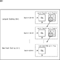
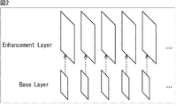
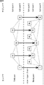
- spatial scalability As a parameter for giving such scalability, for example, there is a spatial resolution as shown in FIG. 2 (spatial scalability). In the case of this spatial scalability (spatial scalability), the resolution is different for each layer. That is, as shown in FIG. 2, enhancement in which each picture is synthesized with a base layer having a spatially lower resolution than the original image and the base layer image to obtain the original image (original spatial resolution). Layered into two layers. Of course, this number of hierarchies is an example, and the number of hierarchies can be hierarchized.
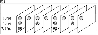
- temporal resolution as shown in FIG. 3 (temporal scalability).
- the frame rate is different for each layer. That is, in this case, as shown in FIG. 3, layers are layered at different frame rates, and by adding a high frame rate layer to a low frame rate layer, a higher frame rate moving image is obtained. By adding all the layers, the original moving image (original frame rate) can be obtained.
- This number of hierarchies is an example, and can be hierarchized to an arbitrary number of hierarchies.
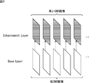
- each picture has two layers of enhancement layers in which the original image (original SNR) is obtained by combining the base layer with a lower SNR than the original image and the base layer image. Is layered.
- the base layer image compression information information related to the low PSNR image is transmitted, and the enhancement layer (enhancement layer) image compression information is added to this to reconstruct a high PSNR image. It is possible.
- this number of hierarchies is an example, and the number of hierarchies can be hierarchized.
- the base layer (base layer) consists of an 8-bit (bit) image, and by adding an enhancement layer (enhancement layer) to this, the bit-depth scalability (bit-depth scalability) can be obtained. is there.
- base layer (base ⁇ ⁇ layer) consists of component images in 4: 2: 0 format, and by adding the enhancement layer (enhancement layer) to this, chroma scalability (chroma) scalability).
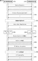
- ⁇ Video parameter set> By the way, in HEVC, in addition to a sequence parameter set (SPS (Sequence Parameter Set)) and a picture parameter set (PPS (Picture Parameter Set)), a video parameter set (VPS (Video Parameter Set) as shown in FIG. Is stipulated.
- SPS Sequence Parameter Set
- PPS Picture Parameter Set
- VPS Video Parameter Set
- Non-Patent Document 2 As shown in FIG. 6, it is proposed to specify on / off of prediction processing between layers in each NAL unit (NAL_Unit) for each picture. It was done.
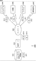
- ⁇ Layer structure> Therefore, a method for more efficiently controlling the prediction process between hierarchies will be considered.
- image data is hierarchized into a plurality of layers.
- this layer is referred to as a main layer.
- Each main layer picture group forms a sequence in the main layer.
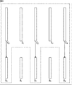
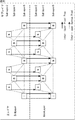
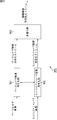
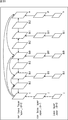
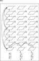
- pictures form a hierarchical structure (GOP (Group Of Picture) structure) as shown in FIG. 7, similarly to moving picture data of a single main layer.
- GOP Group Of Picture
- a layer in this one main layer is referred to as a sublayer.
- the main layer is composed of two layers, a base layer (BaseLayer) and an enhancement layer (EnhLayer).
- the base layer is a layer in which an image is formed only by its own main layer without depending on other main layers.
- the base layer data is encoded / decoded without referring to other main layers.
- the enhancement layer is a main layer from which an image is obtained by being synthesized with the data of the base layer.
- the enhancement layer data can be used for prediction processing with a corresponding base layer (prediction processing between main layers (also referred to as inter-layer prediction)).
- each main layer is a base layer or an enhancement layer, and one of the base layers is set as a reference destination for each enhancement layer.
- the base layer and the enhancement layer each have a GOP structure including three sublayers of sublayer 0 (Sublayer0), sublayer 1 (Sublayer1), and sublayer 2 (Sublayer2).
- a square shown in FIG. 7 indicates a picture, and characters in the square indicate the type of the picture. For example, a square described as “I” indicates an I picture, and a square described as “B” indicates a B picture.
- the dotted line between each square shows a dependence relationship (reference relationship).
- the picture of the upper sublayer depends on the picture of the lower sublayer. That is, the picture of sublayer 2 (Sublayer2) refers to the picture of sublayer 1 or the picture of sublayer 0.
- the sublayer 1 picture refers to the sublayer 0 picture.
- the sublayer 0 picture refers to the sublayer 0 picture as appropriate.
- the number of sublayers (the number of sublayers) is arbitrary.
- the GOP structure is also arbitrary and is not limited to the example of FIG.
- Inter-layer prediction is controlled using sub-layers for image data having such a structure. That is, inter-layer prediction control information for controlling whether or not to perform prediction between a plurality of main layers in each picture is generated and transmitted.
- inter-layer prediction control information for controlling whether or not to perform prediction between a plurality of main layers in each picture is generated and transmitted.
- inter-layer prediction is used only for the sublayers specified in the inter-layer prediction control information.
- inter-layer prediction is used only for the sublayers specified in the inter-layer prediction control information at the time of decoding.
- inter-layer prediction control information only pictures belonging to the sublayer specified by the inter-layer prediction control information can perform inter-layer prediction. That is, it is possible to control inter-layer prediction for all the pictures in the main layer simply by specifying the sublayer. Therefore, it is not necessary to control each picture individually, and it is only necessary to control each main layer, so that the amount of information necessary for the control can be greatly reduced. Therefore, it is possible to suppress a reduction in encoding efficiency due to inter-layer prediction control.
- inter-layer prediction control information information specifying a sub-layer allowing inter-layer prediction may be used, or information specifying a highest sub-layer allowing inter-layer prediction may be used.
- the distance on the time axis between the picture and the reference picture is short. Therefore, the efficiency by the inter prediction process is high, and the improvement of the coding efficiency by the inter-layer prediction is not great.
- the distance between the picture and the reference picture on the time axis is long, and more CUs on which intra prediction is performed are selected in the encoding process using a single layer. . That is, the improvement in coding efficiency by prediction between layers is great.
- inter-layer prediction when inter-layer prediction is performed in some sub-layers, it is desirable to perform control so that inter-layer prediction is performed in sub-layers from the lowest layer to a predetermined lower layer.
- ⁇ Video parameter set> By the way, in HEVC, in addition to a sequence parameter set (SPS (Sequence Parameter Set)) and a picture parameter set (PPS), a video parameter set (VPS (Video Parameter Set)) is defined.
- SPS Sequence Parameter Set
- PPS Picture Parameter Set
- VPS Video Parameter Set
- the video parameter set (VPS) is generated for the entire encoded data that is scalable encoded.
- This video parameter set (VPS) stores information on all main layers.
- a sequence parameter set (SPS) is generated for each main layer.
- SPS sequence parameter set
- information on the main layer is stored.
- a picture parameter set (PPS) is generated for each picture of each main layer.
- PPS picture parameter set
- information related to the picture of the main layer is stored.
- Such inter-layer prediction control information may be transmitted for each main layer in a sequence parameter set (SPS), for example, but is transmitted in a video parameter set (VPS) or the like as common information for all main layers. You may make it do.
- SPS sequence parameter set
- VPN video parameter set
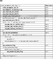
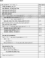
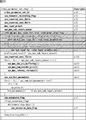
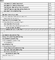
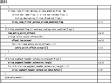
- FIG. 8 shows an example of the syntax of the video parameter set.
- the parameter max_layer_minus1 indicates the maximum number of layers in which scalable coding is performed (that is, the number of main layers).
- the parameter vps_max_sub_layer_minus1 indicates the maximum number of sublayers (maximum number of sublayers) included in each main layer of scalable coding.
- the parameter max_sub_layer_for_inter_layer_prediction [i] indicates a sublayer that performs inter-layer prediction.
- the parameter max_sub_layer_for_inter_layer_prediction [i] indicates the highest sublayer of the sublayer that performs inter-layer prediction. That is, inter-layer prediction is performed in sublayers from the lowest sublayer to the sublayer specified by the parameter max_sub_layer_for_inter_layer_prediction [i].
- This parameter max_sub_layer_for_inter_layer_prediction [i] is set for each main layer (i). That is, the parameter max_sub_layer_for_inter_layer_prediction [i] is set for each of the main layers below the parameter max_layer_minus1. Further, the value of the parameter max_sub_layer_for_inter_layer_prediction [i] is set to a value equal to or smaller than the parameter vps_max_sub_layer_minus1.
- inter-layer prediction can be performed for arbitrary parameters.
- AVC scalable coding
- motion vector information, mode information, decoded pixel values, prediction residual signals, and the like are used for performing inter-layer prediction.
- HEVC in addition to this, there are a flag (flag) relating to orthogonal transform skip (Transform Skip), a reference picture, a quantization parameter, a scaling list (Scaling List), an adaptive offset, and the like.
- the number of parameters for which inter-layer prediction is performed is arbitrary, and may be one or plural.
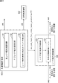
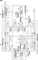
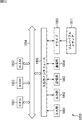
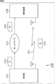
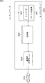
- FIG. 9 is a block diagram illustrating a main configuration example of a scalable encoding device.
- the scalable encoding device 100 shown in FIG. 9 encodes each layer of image data hierarchized into a base layer and an enhancement layer.
- the parameters used as the hierarchization standard are arbitrary.
- the scalable encoding device 100 includes a common information generation unit 101, an encoding control unit 102, a base layer image encoding unit 103, an inter-layer prediction control unit 104, and an enhancement layer image encoding unit 105.
- the common information generation unit 101 acquires information related to encoding of image data that is stored in, for example, a NAL unit. In addition, the common information generation unit 101 acquires necessary information from the base layer image encoding unit 103, the inter-layer prediction control unit 104, the enhancement layer image encoding unit 105, and the like as necessary. The common information generation unit 101 generates common information that is information about all main layers based on the information. The common information includes, for example, a video parameter set. The common information generation unit 101 outputs the generated common information to the outside of the scalable encoding device 100, for example, as a NAL unit. Note that the common information generation unit 101 also supplies the generated common information to the encoding control unit 102.
- the common information generation unit 101 supplies part or all of the generated common information to the base layer image encoding unit 103 to the enhancement layer image encoding unit 105 as necessary.
- the common information generation unit 101 supplies the inter-layer prediction execution maximum sublayer (max_sub_layer_for_inter_layer_prediction [i]) of the current main layer to be processed to the inter-layer prediction control unit 104.
- the encoding control unit 102 controls the base layer image encoding unit 103 to the enhancement layer image encoding unit 105 based on the common information supplied from the common information generation unit 101, thereby encoding each main layer. Control.
- the base layer image encoding unit 103 acquires base layer image information (base layer image information).
- the base layer image encoding unit 103 encodes the base layer image information without referring to other layers, and generates and outputs base layer encoded data (base layer encoded data).
- the base layer image encoding unit 103 supplies information related to base layer encoding obtained at the time of encoding to the inter-layer prediction control unit 104.
- the inter-layer prediction control unit 104 stores information related to base layer encoding supplied from the base layer image encoding unit 103. In addition, the inter-layer prediction control unit 104 acquires the inter-layer prediction execution maximum sublayer (max_sub_layer_for_inter_layer_prediction [i]) of the current main layer supplied from the common information generation unit 101. Based on the information, the inter-layer prediction control unit 104 controls the supply of the stored information related to the base layer encoding to the enhancement layer image encoding unit 105.
- the enhancement layer image encoding unit 105 acquires enhancement layer image information (enhancement layer image information).
- the enhancement layer image encoding unit 105 encodes the enhancement layer image information.
- the enhancement layer image encoding unit 105 performs inter-layer prediction with reference to information on base layer encoding in accordance with the control of the inter-layer prediction control unit 104. More specifically, for example, when the current sublayer to be processed is a sublayer for which inter-layer prediction is permitted, the enhancement layer image encoding unit 105 encodes the base layer code supplied from the inter-layer prediction control unit 104. Information relating to conversion is acquired, inter-layer prediction is performed with reference to the information, and enhancement layer image information is encoded using the prediction result.
- the enhancement layer image encoding unit 105 encodes enhancement layer image information without performing inter-layer prediction.
- the enhancement layer image encoding unit 105 generates and outputs enhancement layer encoded data (enhancement layer encoded data) through such encoding.
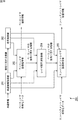
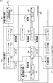
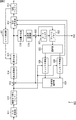
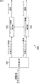
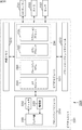
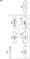
- FIG. 10 is a block diagram illustrating a main configuration example of the base layer image encoding unit 103 in FIG. 9.
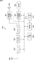
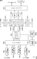
- the base layer image encoding unit 103 includes an A / D conversion unit 111, a screen rearrangement buffer 112, a calculation unit 113, an orthogonal transformation unit 114, a quantization unit 115, a lossless encoding unit 116, The storage buffer 117, the inverse quantization unit 118, and the inverse orthogonal transform unit 119 are included.
- the base layer image encoding unit 103 includes a calculation unit 120, a loop filter 121, a frame memory 122, a selection unit 123, an intra prediction unit 124, a motion prediction / compensation unit 125, a predicted image selection unit 126, and a rate control unit 127.
- the A / D conversion unit 111 performs A / D conversion on the input image data (base layer image information), and supplies the converted image data (digital data) to the screen rearrangement buffer 112 for storage.
- the screen rearrangement buffer 112 rearranges the images of the frames in the stored display order in the order of frames for encoding according to the GOP (Group Of Picture), and rearranges the images in the order of the frames. It supplies to the calculating part 113.
- the screen rearrangement buffer 112 also supplies the image in which the frame order is rearranged to the intra prediction unit 124 and the motion prediction / compensation unit 125.
- the calculation unit 113 subtracts the predicted image supplied from the intra prediction unit 124 or the motion prediction / compensation unit 125 via the predicted image selection unit 126 from the image read from the screen rearrangement buffer 112, and the difference information Is output to the orthogonal transform unit 114. For example, in the case of an image on which intra coding is performed, the calculation unit 113 subtracts the prediction image supplied from the intra prediction unit 124 from the image read from the screen rearrangement buffer 112. For example, in the case of an image on which inter coding is performed, the calculation unit 113 subtracts the prediction image supplied from the motion prediction / compensation unit 125 from the image read from the screen rearrangement buffer 112.
- the orthogonal transform unit 114 performs orthogonal transform such as discrete cosine transform and Karhunen-Loeve transform on the difference information supplied from the computation unit 113.
- the orthogonal transform unit 114 supplies the transform coefficient to the quantization unit 115.
- the quantization unit 115 quantizes the transform coefficient supplied from the orthogonal transform unit 114.
- the quantization unit 115 sets a quantization parameter based on the information regarding the target value of the code amount supplied from the rate control unit 127, and performs the quantization.
- the quantization unit 115 supplies the quantized transform coefficient to the lossless encoding unit 116.
- the lossless encoding unit 116 encodes the transform coefficient quantized by the quantization unit 115 using an arbitrary encoding method. Since the coefficient data is quantized under the control of the rate control unit 127, the code amount becomes the target value set by the rate control unit 127 (or approximates the target value).
- the lossless encoding unit 116 acquires information indicating the intra prediction mode from the intra prediction unit 124, and acquires information indicating the inter prediction mode, difference motion vector information, and the like from the motion prediction / compensation unit 125. Furthermore, the lossless encoding unit 116 appropriately generates a base layer NAL unit including a sequence parameter set (SPS), a picture parameter set (PPS), and the like.
- SPS sequence parameter set
- PPS picture parameter set
- the lossless encoding unit 116 encodes these various types of information by an arbitrary encoding method, and uses (multiplexes) a part of the encoded data (also referred to as an encoded stream).
- the lossless encoding unit 116 supplies the encoded data obtained by encoding to the accumulation buffer 117 for accumulation.
- Examples of the encoding method of the lossless encoding unit 116 include variable length encoding or arithmetic encoding.
- Examples of variable length coding include H.264.
- CAVLC Context-Adaptive Variable Length Coding
- Examples of arithmetic coding include CABAC (Context-Adaptive Binary Arithmetic Coding).
- the cocoon accumulation buffer 117 temporarily holds the encoded data (base layer encoded data) supplied from the lossless encoding unit 116.
- the accumulation buffer 117 outputs the stored base layer encoded data to, for example, a recording device (recording medium) (not shown) or a transmission path at a later stage at a predetermined timing. That is, the accumulation buffer 117 is also a transmission unit that transmits encoded data.
- the transform coefficient quantized by the quantization unit 115 is also supplied to the inverse quantization unit 118.
- the inverse quantization unit 118 inversely quantizes the quantized transform coefficient by a method corresponding to the quantization by the quantization unit 115.
- the inverse quantization unit 118 supplies the obtained transform coefficient to the inverse orthogonal transform unit 119.
- the inverse orthogonal transform unit 119 performs inverse orthogonal transform on the transform coefficient supplied from the inverse quantization unit 118 by a method corresponding to the orthogonal transform processing by the orthogonal transform unit 114.
- the inversely orthogonal transformed output (restored difference information) is supplied to the calculation unit 120.
- the calculation unit 120 uses the prediction image selection unit 126 to perform prediction from the intra prediction unit 124 or the motion prediction / compensation unit 125 on the restored difference information, which is the inverse orthogonal transform result supplied from the inverse orthogonal transform unit 119.
- the images are added to obtain a locally decoded image (decoded image).
- the decoded image is supplied to the loop filter 121 or the frame memory 122.
- the loop filter 121 includes a deblocking filter, an adaptive loop filter, and the like, and appropriately performs a filtering process on the reconstructed image supplied from the calculation unit 120.
- the loop filter 121 removes block distortion of the reconstructed image by performing deblocking filter processing on the reconstructed image.
- the loop filter 121 improves the image quality by performing loop filter processing using a Wiener filter on the deblock filter processing result (reconstructed image from which block distortion has been removed). I do.
- the loop filter 121 supplies a filter processing result (hereinafter referred to as a decoded image) to the frame memory 122.
- the loop filter 121 may further perform other arbitrary filter processing on the reconstructed image. Further, the loop filter 121 can supply information such as filter coefficients used for the filter processing to the lossless encoding unit 116 and encode the information as necessary.
- the kite frame memory 122 stores the supplied decoded image, and supplies the stored decoded image as a reference image to the selection unit 123 at a predetermined timing.
- the frame memory 122 stores the reconstructed image supplied from the calculation unit 120 and the decoded image supplied from the loop filter 121, respectively.
- the frame memory 122 supplies the stored reconstructed image to the intra prediction unit 124 via the selection unit 123 at a predetermined timing or based on a request from the outside such as the intra prediction unit 124.
- the frame memory 122 also stores the decoded image stored at a predetermined timing or based on a request from the outside such as the motion prediction / compensation unit 125 via the selection unit 123. 125.
- the eyelid selection unit 123 selects a supply destination of the reference image supplied from the frame memory 122. For example, in the case of intra prediction, the selection unit 123 supplies the reference image (pixel value in the current picture) supplied from the frame memory 122 to the intra prediction unit 124. For example, in the case of inter prediction, the selection unit 123 supplies the reference image supplied from the frame memory 122 to the motion prediction / compensation unit 125.
- the intra prediction unit 124 performs intra prediction (intra-screen prediction) that generates a predicted image using a pixel value in a current picture that is a reference image supplied from the frame memory 122 via the selection unit 123.
- the intra prediction unit 124 performs this intra prediction in a plurality of intra prediction modes prepared in advance.
- the intra prediction unit 124 generates prediction images in all candidate intra prediction modes, evaluates the cost function value of each prediction image using the input image supplied from the screen rearrangement buffer 112, and selects the optimum mode. select. When the optimal intra prediction mode is selected, the intra prediction unit 124 supplies the predicted image generated in the optimal mode to the predicted image selection unit 126.
- the intra prediction unit 124 appropriately supplies the intra prediction mode information indicating the adopted intra prediction mode to the lossless encoding unit 116 for encoding.
- the heel motion prediction / compensation unit 125 performs motion prediction (inter prediction) using the input image supplied from the screen rearrangement buffer 112 and the reference image supplied from the frame memory 122 via the selection unit 123.
- the motion prediction / compensation unit 125 performs a motion compensation process according to the detected motion vector, and generates a prediction image (inter prediction image information).
- the motion prediction / compensation unit 125 performs such inter prediction in a plurality of inter prediction modes prepared in advance.
- the heel motion prediction / compensation unit 125 generates a prediction image in all candidate inter prediction modes.
- the motion prediction / compensation unit 125 evaluates the cost function value of each predicted image using the input image supplied from the screen rearrangement buffer 112 and information on the generated differential motion vector, and selects an optimal mode. .
- the motion prediction / compensation unit 125 supplies the predicted image generated in the optimal mode to the predicted image selection unit 126.
- the motion prediction / compensation unit 125 supplies information indicating the employed inter prediction mode, information necessary for performing processing in the inter prediction mode, and the like to the lossless encoding unit 116 when decoding the encoded data. And encoding.
- the necessary information includes, for example, information on the generated differential motion vector and a flag indicating an index of the predicted motion vector as predicted motion vector information.
- the predicted image selection unit 126 selects a supply source of the predicted image to be supplied to the calculation unit 113 or the calculation unit 120.
- the prediction image selection unit 126 selects the intra prediction unit 124 as a supply source of the prediction image, and supplies the prediction image supplied from the intra prediction unit 124 to the calculation unit 113 and the calculation unit 120.
- the predicted image selection unit 126 selects the motion prediction / compensation unit 125 as a supply source of the predicted image, and calculates the predicted image supplied from the motion prediction / compensation unit 125 as the calculation unit 113.
- the rate control unit 127 controls the rate of the quantization operation of the quantization unit 115 based on the code amount of the encoded data stored in the storage buffer 117 so that no overflow or underflow occurs.
- the frame memory 122 supplies the stored decoded image to the inter-layer prediction control unit 104 as information related to base layer encoding.
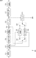
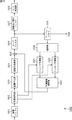
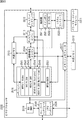
- FIG. 11 is a block diagram illustrating a main configuration example of the enhancement layer image encoding unit 105 in FIG. 9. As shown in FIG. 11, the enhancement layer image encoding unit 105 has basically the same configuration as the base layer image encoding unit 103 of FIG. 10.
- each unit of the enhancement layer image encoding unit 105 performs processing for encoding enhancement layer image information, not the base layer. That is, the A / D conversion unit 111 of the enhancement layer image encoding unit 105 performs A / D conversion on the enhancement layer image information, and the accumulation buffer 117 of the enhancement layer image encoding unit 105 converts the enhancement layer encoded data into, for example, Then, the data is output to a recording device (recording medium), a transmission path, etc., not shown.
- the enhancement layer image encoding unit 105 includes a motion prediction / compensation unit 135 instead of the motion prediction / compensation unit 125.
- the motion prediction / compensation unit 135 can perform not only motion prediction between pictures as the motion prediction / compensation unit 125 performs, but also motion prediction between main layers.
- the motion prediction / compensation unit 135 acquires information (for example, a decoded image of the base layer) regarding base layer encoding supplied from the inter-layer prediction control unit 104.
- the motion prediction / compensation unit 135 performs motion prediction of the main layer using information regarding the encoding of the base layer as one of the candidate modes for inter prediction.
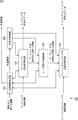
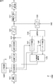
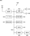
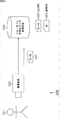
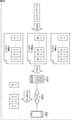
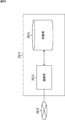
- ⁇ Common information generator and inter-layer prediction controller> 12 is a block diagram illustrating a main configuration example of the common information generation unit 101 and the inter-layer prediction control unit 104 in FIG.
- the common information generating unit 101 includes a main layer maximum number setting unit 141, a sublayer maximum number setting unit 142, and an inter-layer prediction execution maximum sublayer setting unit 143.
- the inter-layer prediction control unit 104 includes an inter-layer prediction execution control unit 151 and an encoding related information buffer 152.
- the main layer maximum number setting unit 141 sets information (max_layer_minus1) indicating the maximum number of main layers.
- the sublayer maximum number setting unit 142 sets information (vps_max_sub_layer_minus1) indicating the maximum number of sublayers.
- the inter-layer prediction execution maximum sublayer setting unit 143 sets information (max_sub_layer_for_inter_layer_prediction [i]) that specifies the highest sublayer of the sublayer that permits inter-layer prediction of the current main layer.
- the common information generation unit 101 outputs the information as common information (video parameter set (VPS)) to the outside of the scalable encoding device 100.
- the common information generation unit 101 supplies the common information (video parameter set (VPS)) to the encoding control unit 102.
- the common information generation unit 101 supplies information (max_sub_layer_for_inter_layer_prediction [i]) specifying the highest sublayer of the sublayer that permits inter-layer prediction of the current main layer to the inter-layer prediction control unit 104.
- the inter-layer prediction execution control unit 151 controls execution of inter-layer prediction based on the common information supplied from the common information generation unit 101. More specifically, the inter-layer prediction execution control unit 151 is based on the information (max_sub_layer_for_inter_layer_prediction [i]) that is supplied from the common information generation unit 101 and specifies the highest sublayer of the sublayer that permits inter-layer prediction.
- the encoding related information buffer 152 is controlled.
- the encoding related information buffer 152 acquires and stores information related to base layer encoding (for example, a base layer decoded image) supplied from the base layer image encoding unit 103.
- the encoding related information buffer 152 supplies the stored information related to base layer encoding to the enhancement layer image encoding unit 105 in accordance with the control of the inter-layer prediction execution control unit 151.
- the inter-layer prediction execution control unit 151 controls the supply of information related to base layer encoding from the encoding related information buffer 152. For example, in the information (max_sub_layer_for_inter_layer_prediction [i]) that specifies the highest sublayer of the sublayer that permits inter-layer prediction, when inter-layer prediction of the current sub-layer is permitted, the inter-layer prediction execution control unit 151
- the enhancement layer image encoding unit 105 is supplied with information related to the encoding of the base layer (for example, the decoded image of the base layer) stored in the encoding related information buffer 152.
- the inter-layer prediction execution control unit 151 For the sublayer, information related to base layer encoding (for example, a base layer decoded image) stored in the encoding related information buffer 152 is not supplied to the enhancement layer image encoding unit 105.
- scalable encoding apparatus 100 transmits inter-layer prediction control information for controlling inter-layer prediction using sublayers, it is possible to suppress a reduction in encoding efficiency due to inter-layer prediction control. Thereby, the scalable encoding device 100 can suppress a reduction in image quality due to encoding / decoding.
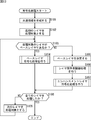
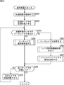
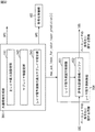
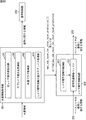
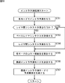
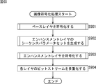
- step S101 the common information generation unit 101 of the scalable encoding device 100 generates common information.
- step S102 the encoding control unit 102 sets the first main layer as a processing target.
- step S103 the encoding control unit 102 determines whether the current main layer to be processed is a base layer based on the common information generated in step S101. If it is determined that the current main layer is the base layer, the process proceeds to step S104.
- step S104 the base layer image encoding unit 103 performs base layer encoding processing.
- step S104 the process proceeds to step S108.
- step S103 If it is determined in step S103 that the current main layer is an enhancement layer, the process proceeds to step S105.
- step S105 the encoding control unit 102 determines a base layer corresponding to the current main layer (that is, a reference destination).
- step S106 the inter-layer prediction control unit 104 performs an inter-layer prediction control process.
- step S107 the enhancement layer image encoding unit 105 performs enhancement layer encoding processing.
- step S108 the process proceeds to step S108.
- step S108 the encoding control unit 102 determines whether all main layers have been processed. If it is determined that there is an unprocessed main layer, the process proceeds to step S109.
- step S109 the encoding control unit 102 sets the next unprocessed main layer as a processing target (current main layer).
- the process of step S109 ends, the process returns to step S103.
- the processing from step S103 to step S109 is repeatedly executed, and each main layer is encoded.
- step S108 If it is determined in step S108 that all the main layers have been processed, the encoding process ends.
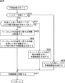
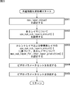
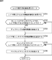
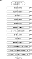
- the main layer maximum number setting unit 141 sets a parameter (max_layer_minus1) in step S121.
- the sublayer maximum number setting unit 142 sets a parameter (vps_max_sub_layers_minus1).
- the inter-layer prediction execution maximum sublayer setting unit 143 sets a parameter (max_sub_layer_for_inter_layer_prediction [i]) for each main layer.
- step S124 the common information generation unit 101 generates a video parameter set including each parameter set in steps S121 to S123 as common information.
- step S125 the common information generation unit 101 supplies the video parameter set generated by the processing in step S124 to the outside of the scalable encoding device 100 and the encoding control unit 102. Further, the common information generation unit 101 supplies the parameter (max_sub_layer_for_inter_layer_prediction [i]) set in step S123 to the inter-layer prediction control unit 104.
- step S125 When the process of step S125 ends, the common information generation process ends, and the process returns to FIG.
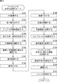
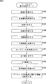
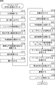
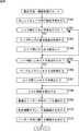
- step S141 the A / D conversion unit 111 of the base layer image encoding unit 103 performs A / D conversion on the input base layer image information (image data).
- step S142 the screen rearrangement buffer 112 stores the A / D converted base layer image information (digital data), and rearranges the pictures from the display order to the encoding order.
- step S143 the intra prediction unit 124 performs an intra prediction process in the intra prediction mode.
- step S144 the motion prediction / compensation unit 125 performs motion prediction / compensation processing for performing motion prediction and motion compensation in the inter prediction mode.
- step S145 the predicted image selection unit 126 determines an optimal mode based on the cost function values output from the intra prediction unit 124 and the motion prediction / compensation unit 125. That is, the predicted image selection unit 126 selects one of the predicted image generated by the intra prediction unit 124 and the predicted image generated by the motion prediction / compensation unit 125.
- step S146 the calculation unit 113 calculates a difference between the image rearranged by the process of step S142 and the predicted image selected by the process of step S145. The data amount of the difference data is reduced compared to the original image data. Therefore, the data amount can be compressed as compared with the case where the image is encoded as it is.
- step S147 the orthogonal transform unit 114 performs an orthogonal transform process on the difference information generated by the process in step S146.
- step S148 the quantization unit 115 quantizes the orthogonal transform coefficient obtained by the process in step S147 using the quantization parameter calculated by the rate control unit 127.
- the difference information quantized by the processing in step S148 is locally decoded as follows. That is, in step S149, the inverse quantization unit 118 inversely quantizes the quantized coefficient (also referred to as quantization coefficient) generated by the process in step S148 with characteristics corresponding to the characteristics of the quantization unit 115. . In step S150, the inverse orthogonal transform unit 119 performs inverse orthogonal transform on the orthogonal transform coefficient obtained by the process of step S147. In step S151, the calculation unit 120 adds the predicted image to the locally decoded difference information, and generates a locally decoded image (an image corresponding to the input to the calculation unit 113).
- step S152 the loop filter 121 filters the image generated by the process in step S151. Thereby, block distortion and the like are removed.
- step S153 the frame memory 122 stores an image from which block distortion has been removed by the process of step S152. Note that an image that has not been filtered by the loop filter 121 is also supplied to the frame memory 122 from the computing unit 120 and stored therein. The image stored in the frame memory 122 is used for the processing in step S143 and the processing in step S144.
- step S154 the frame memory 122 supplies the image stored in the frame memory 122 to the inter-layer prediction control unit 104 as information related to the encoding of the base layer, and stores it.
- step S155 the lossless encoding unit 116 encodes the coefficient quantized by the process in step S148. That is, lossless encoding such as variable length encoding or arithmetic encoding is performed on the data corresponding to the difference image.
- the lossless encoding unit 116 encodes information regarding the prediction mode of the prediction image selected by the process of step S145, and adds the encoded information to the encoded data obtained by encoding the difference image. That is, the lossless encoding unit 116 encodes and encodes the optimal intra prediction mode information supplied from the intra prediction unit 124 or the information corresponding to the optimal inter prediction mode supplied from the motion prediction / compensation unit 125. Append to data.
- step S156 the accumulation buffer 117 accumulates the base layer encoded data obtained by the process in step S155.
- the base layer encoded data stored in the storage buffer 117 is appropriately read and transmitted to the decoding side via a transmission path or a recording medium.
- step S157 the rate control unit 127 causes the quantization unit 115 to prevent overflow or underflow from occurring based on the code amount (generated code amount) of the encoded data accumulated in the accumulation buffer 117 by the process of step S156. Controls the rate of quantization operation. Further, the rate control unit 127 supplies information regarding the quantization parameter to the quantization unit 115.
- the base layer encoding process is completed, and the process returns to FIG.
- the base layer encoding process is executed in units of pictures, for example. That is, the base layer encoding process is executed for each picture in the current layer. However, each process in the base layer encoding process is performed for each processing unit.
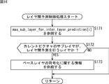
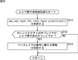
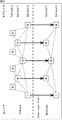
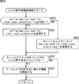
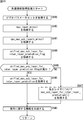
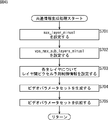
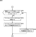
- the inter-layer prediction execution control unit 151 refers to the parameter (max_sub_layer_for_inter_layer_prediction [i]) supplied from the common information generation unit 101 by the common information generation process of FIG. 14 in step S171. To do.
- step S172 the inter-layer prediction execution control unit 151 determines whether the current sublayer of the current picture is a layer that performs inter-layer prediction based on the parameter value.
- the process proceeds to step S173.
- step S173 the inter-layer prediction execution control unit 151 controls the encoding related information buffer 152, and the enhancement layer image encoding unit 105 stores information related to base layer encoding stored in the encoding related information buffer 152. To supply.
- step S173 ends, the inter-layer prediction control process ends, and the process returns to FIG.
- step S172 If it is determined in step S172 that inter-layer prediction in the current sublayer is not permitted, the information related to base layer encoding is not supplied, and the inter-layer prediction control process is terminated. Return to. That is, inter-layer prediction is not performed in the encoding for the current sublayer.
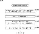
- Steps S191 to S193 of the enhancement layer encoding process and steps S195 to S206 are the same as steps S141 to S143, step S145 to S153, and steps S155 to S157 of the base layer encoding process. It is executed in the same manner as each process. However, each process of the enhancement layer encoding process is performed on the enhancement layer image information by each processing unit of the enhancement layer image encoding unit 105.
- step S194 the motion prediction / compensation unit 135 performs motion prediction / compensation processing on the enhancement layer image information.
- the enhancement layer encoding process ends, and the process returns to FIG.
- the enhancement layer encoding process is executed in units of pictures, for example. That is, the enhancement layer encoding process is executed for each picture in the current layer. However, each process in the enhancement layer encoding process is performed for each processing unit.
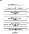
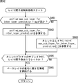
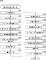
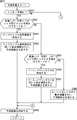
- the motion prediction / compensation unit 135 When the motion prediction / compensation process is started, the motion prediction / compensation unit 135 performs motion prediction in the current main layer in step S221.
- step S222 the motion prediction / compensation unit 135 determines whether or not to perform inter-layer prediction for the current picture.
- the process proceeds to step S223.
- step S ⁇ b> 223 the motion prediction / compensation unit 135 acquires information related to base layer encoding supplied from the inter-layer prediction control unit 104.
- step S224 the motion prediction / compensation unit 135 performs inter-layer prediction using the information acquired in step S223.
- the process of step S224 ends, the process proceeds to step S225.
- step S222 when information related to base layer encoding is not supplied from the inter-layer prediction control unit 104 and it is determined not to perform inter-layer prediction, inter-layer prediction is omitted for the current picture, and processing is performed. Advances to step S225.
- step S225 the motion prediction / compensation unit 135 calculates a cost function value for each prediction mode.
- step S226 the motion prediction / compensation unit 135 selects an optimal inter prediction mode based on the cost function value.
- step S227 the motion prediction / compensation unit 135 performs motion compensation in the optimal inter prediction mode selected in step S226, and generates a predicted image.
- step S228 When the process of step S228 ends, the motion prediction / compensation process ends, and the process returns to FIG. As described above, motion prediction / compensation processing using inter-layer prediction as appropriate is performed. This process is executed in units of blocks, for example. However, each process in the motion prediction / compensation process is performed for each processing unit.
- the scalable encoding device 100 can suppress a reduction in encoding efficiency and an image quality due to encoding / decoding.
- FIG. 19 is a block diagram illustrating a main configuration example of a scalable decoding device corresponding to the scalable encoding device 100 in FIG. 9.
- a scalable decoding device 200 shown in FIG. 19 performs scalable decoding on encoded data obtained by scalable encoding of image data by the scalable encoding device 100 by a method corresponding to the encoding method, for example.
- the scalable decoding device 200 includes a common information acquisition unit 201, a decoding control unit 202, a base layer image decoding unit 203, an inter-layer prediction control unit 204, and an enhancement layer image decoding unit 205.
- the common information acquisition unit 201 acquires common information (for example, a video parameter set (VPS)) transmitted from the encoding side.
- the common information acquisition unit 201 extracts information related to decoding from the acquired common information and supplies it to the decoding control unit 202.
- the common information acquisition unit 201 supplies part or all of the common information to the base layer image decoding unit 203 to the enhancement layer image decoding unit 205 as appropriate.
- the decoding control unit 202 acquires the information related to decoding supplied from the common information acquisition unit 201, and controls the base layer image decoding unit 203 to the enhancement layer image decoding unit 205 based on the information, whereby each main layer Control the decoding of.
- the base layer image decoding unit 203 is an image decoding unit corresponding to the base layer image encoding unit 103, and for example, base layer encoded data obtained by encoding base layer image information by the base layer image encoding unit 103. To get.
- the base layer image decoding unit 203 decodes the base layer encoded data without referring to other layers, reconstructs the base layer image information, and outputs it.
- the base layer image decoding unit 203 supplies information related to decoding of the base layer obtained by the decoding to the inter-layer prediction control unit 204.
- the inter-layer prediction control unit 204 controls execution of inter-layer prediction by the enhancement layer image decoding unit 205.
- the inter-layer prediction control unit 204 acquires and stores information related to base layer decoding supplied from the base layer image decoding unit 203.
- the inter-layer prediction control unit 204 supplies the stored information regarding the decoding of the base layer to the enhancement layer image decoding unit 205 in the decoding of the sub-layer for which inter-layer prediction is permitted.
- the enhancement layer image decoding unit 205 is an image decoding unit corresponding to the enhancement layer image encoding unit 105, for example, enhancement layer encoded data obtained by encoding enhancement layer image information by the enhancement layer image encoding unit 105. To get.
- the enhancement layer image decoding unit 205 decodes the enhancement layer encoded data.
- the enhancement layer image decoding unit 205 performs inter-layer prediction with reference to information on decoding of the base layer according to the control of the inter-layer prediction control unit 204. More specifically, for example, when the current sublayer to be processed is a sublayer for which inter-layer prediction is permitted, the enhancement layer image decoding unit 205 relates to decoding of the base layer supplied from the inter-layer prediction control unit 204.
- enhancement layer encoded data is decoded using the prediction result.
- the enhancement layer image decoding unit 205 decodes enhancement layer encoded data without performing inter-layer prediction.
- the enhancement layer image decoding unit 205 reconstructs and outputs enhancement layer image information by such encoding.
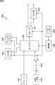
- FIG. 20 is a block diagram illustrating a main configuration example of the base layer image decoding unit 203 in FIG.
- the base layer image decoding unit 203 includes a storage buffer 211, a lossless decoding unit 212, an inverse quantization unit 213, an inverse orthogonal transform unit 214, a calculation unit 215, a loop filter 216, a screen rearrangement buffer 217, And a D / A converter 218.
- the base layer image decoding unit 203 includes a frame memory 219, a selection unit 220, an intra prediction unit 221, a motion compensation unit 222, and a selection unit 223.
- Accumulation buffer 211 is also a receiving unit that receives transmitted base layer encoded data.
- the accumulation buffer 211 receives and accumulates the transmitted base layer encoded data, and supplies the encoded data to the lossless decoding unit 212 at a predetermined timing.
- Information necessary for decoding such as prediction mode information is added to the base layer encoded data.
- the lossless decoding unit 212 decodes the information supplied from the accumulation buffer 211 and encoded by the lossless encoding unit 116 by a method corresponding to the encoding method of the lossless encoding unit 116.
- the lossless decoding unit 212 supplies the quantized coefficient data of the difference image obtained by decoding to the inverse quantization unit 213.
- the lossless decoding unit 212 appropriately extracts and acquires NAL units including a video parameter set (VPS), a sequence parameter set (SPS), a picture parameter set (PPS), and the like included in the base layer encoded data.
- the lossless decoding unit 212 extracts information on the optimum prediction mode from the information, determines whether the intra prediction mode or the inter prediction mode is selected as the optimum prediction mode based on the information, and Information regarding the optimal prediction mode is supplied to the mode determined to be selected from the intra prediction unit 221 and the motion compensation unit 222. That is, for example, when the intra prediction mode is selected as the optimal prediction mode in the base layer image encoding unit 103, information regarding the optimal prediction mode is supplied to the intra prediction unit 221. For example, when the inter prediction mode is selected as the optimal prediction mode in the base layer image encoding unit 103, information regarding the optimal prediction mode is supplied to the motion compensation unit 222.
- the lossless decoding unit 212 extracts information necessary for inverse quantization, such as a quantization matrix and a quantization parameter, from the NAL unit or the like, and supplies it to the inverse quantization unit 213.
- the inverse quantization unit 213 inversely quantizes the quantized coefficient data obtained by decoding by the lossless decoding unit 212 using a method corresponding to the quantization method of the quantization unit 115.
- the inverse quantization unit 213 is a processing unit similar to the inverse quantization unit 118. That is, the description of the inverse quantization unit 213 can be applied to the inverse quantization unit 118. However, the data input / output destinations and the like need to be changed appropriately according to the device.
- the inverse quantization unit 213 supplies the obtained coefficient data to the inverse orthogonal transform unit 214.
- the inverse orthogonal transform unit 214 performs inverse orthogonal transform on the coefficient data supplied from the inverse quantization unit 213 using a method corresponding to the orthogonal transform method of the orthogonal transform unit 114.
- the inverse orthogonal transform unit 214 is a processing unit similar to the inverse orthogonal transform unit 119. That is, the description of the inverse orthogonal transform unit 214 can be applied to the inverse orthogonal transform unit 119. However, the data input / output destinations and the like need to be changed appropriately according to the device.
- the inverse orthogonal transform unit 214 obtains decoded residual data corresponding to the residual data before being orthogonally transformed by the orthogonal transform unit 114 by the inverse orthogonal transform process.
- the decoded residual data obtained by the inverse orthogonal transform is supplied to the calculation unit 215.
- a prediction image is supplied to the calculation unit 215 from the intra prediction unit 221 or the motion compensation unit 222 via the selection unit 223.
- the calculating unit 215 adds the decoded residual data and the predicted image, and obtains decoded image data corresponding to the image data before the predicted image is subtracted by the calculating unit 113.
- the arithmetic unit 215 supplies the decoded image data to the loop filter 216.
- the loop filter 216 appropriately performs filtering processing including a deblocking filter and an adaptive loop filter on the supplied decoded image, and supplies it to the screen rearranging buffer 217 and the frame memory 219.
- the loop filter 216 removes block distortion of the decoded image by performing a deblocking filter process on the decoded image.
- the loop filter 216 performs image quality improvement by performing loop filter processing using a Wiener filter on the deblock filter processing result (decoded image from which block distortion has been removed). Do.
- the loop filter 216 is a processing unit similar to the loop filter 121.
- the decoded image output from the calculation unit 215 can be supplied to the screen rearrangement buffer 217 and the frame memory 219 without passing through the loop filter 216. That is, part or all of the filter processing by the loop filter 216 can be omitted.
- the screen rearrangement buffer 217 rearranges the decoded images. That is, the order of frames rearranged for the encoding order by the screen rearrangement buffer 112 is rearranged in the original display order.
- the D / A conversion unit 218 performs D / A conversion on the image supplied from the screen rearrangement buffer 217, and outputs and displays the image on a display (not shown).
- the frame memory 219 stores the supplied decoded image, and uses the stored decoded image as a reference image at a predetermined timing or based on an external request such as the intra prediction unit 221 or the motion compensation unit 222. This is supplied to the selection unit 220.
- the frame memory 219 supplies the stored decoded image to the inter-layer prediction control unit 204 as information related to base layer decoding.
- the eyelid selection unit 220 selects a reference image supply destination supplied from the frame memory 219.
- the selection unit 220 supplies the reference image supplied from the frame memory 219 to the intra prediction unit 221 when decoding an intra-coded image.
- the selection unit 220 supplies the reference image supplied from the frame memory 219 to the motion compensation unit 222 when decoding an inter-encoded image.
- the intra prediction unit 221 is appropriately supplied with information indicating the intra prediction mode obtained by decoding the header information from the lossless decoding unit 212.
- the intra prediction unit 221 performs intra prediction using the reference image acquired from the frame memory 219 in the intra prediction mode used in the intra prediction unit 124, and generates a predicted image.
- the intra prediction unit 221 supplies the generated predicted image to the selection unit 223.
- the eyelid motion compensation unit 222 acquires information (optimum prediction mode information, reference image information, etc.) obtained by decoding the header information from the lossless decoding unit 212.
- the heel motion compensation unit 222 performs motion compensation using the reference image acquired from the frame memory 219 in the inter prediction mode indicated by the optimal prediction mode information acquired from the lossless decoding unit 212, and generates a predicted image.
- the eyelid selection unit 223 supplies the prediction image from the intra prediction unit 221 or the prediction image from the motion compensation unit 222 to the calculation unit 215.
- the arithmetic unit 215 adds the predicted image generated using the motion vector and the decoded residual data (difference image information) from the inverse orthogonal transform unit 214 to decode the original image.
- FIG. 21 is a block diagram illustrating a main configuration example of the enhancement layer image decoding unit 205 of FIG. As shown in FIG. 21, the enhancement layer image decoding unit 205 has basically the same configuration as the base layer image decoding unit 203 of FIG.
- each unit of the enhancement layer image decoding unit 205 performs a process for decoding enhancement layer encoded data, not the base layer. That is, the accumulation buffer 211 of the enhancement layer image decoding unit 205 stores the enhancement layer encoded data, and the D / A conversion unit 218 of the enhancement layer image decoding unit 205 displays the enhancement layer image information, for example, in the subsequent stage. Output to a recording device (recording medium) or transmission path.
- the enhancement layer image decoding unit 205 includes a motion compensation unit 232 instead of the motion compensation unit 222.
- the motion compensation unit 232 can perform not only motion compensation between pictures as the motion compensation unit 222 performs, but also motion compensation between main layers.
- the motion compensation unit 232 acquires information (for example, a decoded image of the base layer) related to decoding of the base layer supplied from the inter-layer prediction control unit 204.
- the motion compensation unit 232 performs motion compensation of the main layer using information regarding decoding of the base layer.
- FIG. 22 is a block diagram illustrating a main configuration example of the common information acquisition unit 201 and the inter-layer prediction control unit 204 in FIG.
- the common information acquisition unit 201 includes a main layer maximum number acquisition unit 241, a sublayer maximum number acquisition unit 242, and an inter-layer prediction execution maximum sublayer acquisition unit 243.
- the inter-layer prediction control unit 204 includes an inter-layer prediction execution control unit 251 and a decoding related information buffer 252.
- the main layer maximum number acquisition unit 241 acquires information (max_layer_minus1) indicating the maximum number of main layers included in the common information transmitted from the encoding side.
- the sublayer maximum number acquisition unit 242 acquires information (vps_max_sub_layer_minus1) indicating the maximum number of sublayers included in the common information transmitted from the encoding side.
- the inter-layer prediction execution maximum sublayer acquisition unit 243 acquires information (max_sub_layer_for_inter_layer_prediction [i]) that specifies the highest sublayer of the sublayer that allows inter-layer prediction of the current main layer included in the common information transmitted from the encoding side. To do.
- the common information acquisition unit 201 supplies information related to decoding (for example, a video parameter set (VPS)) included in the acquired common information to the decoding control unit 202. Furthermore, the common information acquisition unit 201 supplies information (max_sub_layer_for_inter_layer_prediction [i]) specifying the highest sublayer of the sublayer that permits inter-layer prediction of the current main layer to the inter-layer prediction control unit 204.
- decoding for example, a video parameter set (VPS)
- VPS video parameter set
- the inter-layer prediction execution control unit 251 controls execution of inter-layer prediction based on the common information supplied from the common information acquisition unit 201. More specifically, the inter-layer prediction execution control unit 251 is based on the information (max_sub_layer_for_inter_layer_prediction [i]) that is supplied from the common information acquisition unit 201 and specifies the highest sublayer of the sublayer that permits inter-layer prediction.
- the decoding related information buffer 252 is controlled.
- Decoding related information buffer 252 acquires and stores information related to base layer decoding (for example, a base layer decoded image) supplied from base layer image decoding section 203.
- the decoding related information buffer 252 supplies the stored information related to the encoding of the base layer to the enhancement layer image decoding unit 205 according to the control of the inter-layer prediction execution control unit 251.
- the inter-layer prediction execution control unit 251 controls supply of information related to decoding of the base layer from the decoding related information buffer 252. For example, in the information (max_sub_layer_for_inter_layer_prediction [i]) designating the highest sublayer of the sublayer that permits inter-layer prediction, when inter-layer prediction of the current sub-layer is permitted, the inter-layer prediction execution control unit 251 Then, the enhancement layer image decoding unit 205 is supplied with the information related to the decoding of the base layer (for example, the decoded image of the base layer) stored in the decoding related information buffer 252.
- the inter-layer prediction execution control unit 251 For the sublayer, the enhancement layer image decoding unit 205 does not supply the information related to the decoding of the base layer (for example, the decoded image of the base layer) stored in the decoding related information buffer 252.
- scalable decoding apparatus 200 transmits inter-layer prediction control information for controlling inter-layer prediction using sublayers, it is possible to suppress a reduction in coding efficiency due to inter-layer prediction control. Thereby, the scalable decoding device 200 can suppress a reduction in image quality due to encoding / decoding.
- step S301 the common information acquisition unit 201 of the scalable decoding device 200 acquires common information.
- step S302 the decoding control unit 202 sets the first main layer as a processing target.
- step S303 the decoding control unit 202 determines whether or not the current main layer to be processed is a base layer, based on the common information transmitted from the encoding side acquired in step S301. If it is determined that the current main layer is the base layer, the process proceeds to step S304.
- step S304 the base layer image decoding unit 203 performs base layer decoding processing.
- the process of step S304 ends the process proceeds to step S308.
- step S303 If it is determined in step S303 that the current main layer is an enhancement layer, the process proceeds to step S305.
- step S305 the decoding control unit 202 determines a base layer corresponding to the current main layer (that is, a reference destination).
- step S306 the inter-layer prediction control unit 204 performs an inter-layer prediction control process.
- step S307 the enhancement layer image decoding unit 205 performs enhancement layer decoding processing.
- the process of step S307 ends the process proceeds to step S308.
- step S308 the decoding control unit 202 determines whether all main layers have been processed. If it is determined that there is an unprocessed main layer, the process proceeds to step S309.
- step S309 the decoding control unit 202 sets the next unprocessed main layer as a processing target (current main layer).
- the process of step S309 ends, the process returns to step S303.
- the processing from step S303 to step S309 is repeatedly executed, and each main layer is decoded.
- step S308 If it is determined in step S308 that all main layers have been processed, the decoding process ends.
- the common information acquisition unit 201 acquires a video parameter set (VPS) transmitted from the encoding side in step S321.
- VPS video parameter set
- step S322 the main layer maximum number acquisition unit 241 acquires a parameter (max_layer_minus1) from the video parameter set.
- step S323 the sublayer maximum number acquisition unit 242 acquires a parameter (vps_max_sub_layers_minus1) from the video parameter set.
- step S324 the inter-layer prediction execution maximum sublayer acquisition unit 243 acquires a parameter (max_sub_layer_for_inter_layer_prediction [i]) for each main layer.
- step S325 the common information acquisition unit 201 extracts information necessary for decoding control from the video parameter set, and supplies the information to the decoding control unit 202 as information related to decoding.
- step S325 When the process of step S325 ends, the common information acquisition process ends, and the process returns to FIG.
- step S341 the accumulation buffer 211 of the base layer image decoding unit 203 accumulates the base layer bit stream transmitted from the encoding side.
- step S342 the lossless decoding unit 212 decodes the base layer bit stream (encoded difference image information) supplied from the accumulation buffer 211. That is, the I picture, P picture, and B picture encoded by the lossless encoding unit 116 are decoded. At this time, various information other than the difference image information included in the bit stream such as header information is also decoded.
- step S343 the inverse quantization unit 213 inversely quantizes the quantized coefficient obtained by the process in step S342.
- step S344 the inverse orthogonal transform unit 214 performs inverse orthogonal transform on the current block (current TU).
- step S345 the intra prediction unit 221 or the motion compensation unit 222 performs a prediction process to generate a predicted image. That is, the prediction process is performed in the prediction mode that is determined in the lossless decoding unit 212 and applied at the time of encoding. More specifically, for example, when intra prediction is applied at the time of encoding, the intra prediction unit 221 generates a prediction image in the intra prediction mode that is optimized at the time of encoding. For example, when inter prediction is applied at the time of encoding, the motion compensation unit 222 generates a prediction image in an inter prediction mode that is optimized at the time of encoding.
- step S346 the calculation unit 215 adds the predicted image generated in step S345 to the difference image information generated by the inverse orthogonal transform process in step S344. As a result, the original image is decoded.
- step S347 the loop filter 216 appropriately performs loop filter processing on the decoded image obtained in step S346.
- step S348 the screen rearrangement buffer 217 rearranges the images filtered in step S347. That is, the order of frames rearranged for encoding by the screen rearrangement buffer 112 is rearranged in the original display order.
- step S349 the D / A conversion unit 218 performs D / A conversion on the image in which the frame order is rearranged in step S348. This image is output to a display (not shown), and the image is displayed.
- step S350 the frame memory 219 stores the image subjected to the loop filter process in step S347.
- step S351 the frame memory 219 supplies the decoded image stored in step S350 to the decoding related information buffer 252 of the inter-layer prediction control unit 204 as information related to decoding of the base layer, and stores it therein.
- the base layer decoding process ends, and the process returns to FIG.
- the base layer decoding process is executed in units of pictures, for example. That is, the base layer decoding process is executed for each picture in the current layer. However, each process in the base layer decoding process is performed for each processing unit.
- the inter-layer prediction execution control unit 251 refers to the parameter (max_sub_layer_for_inter_layer_prediction [i]) supplied from the common information acquisition unit 201 by the common information generation process in FIG. 24 in step S371. To do.
- step S372 the inter-layer prediction execution control unit 251 determines whether or not the current sublayer of the current picture is a layer that performs inter-layer prediction based on the parameter value.
- the process proceeds to step S373.
- step S373 the inter-layer prediction execution control unit 251 controls the decoding related information buffer 252, and causes the enhancement layer image decoding unit 205 to supply information related to base layer decoding stored in the decoding related information buffer 252.
- the inter-layer prediction control process ends, and the process returns to FIG.
- step S372 If it is determined in step S372 that inter-layer prediction in the current sublayer is not permitted, the information related to base layer coding is not supplied, and the inter-layer prediction control process is terminated. Return to. That is, inter-layer prediction is not performed in the encoding for the current sublayer.
- Steps S391 to S394 and steps S396 to S400 of the enhancement layer decoding process are executed in the same manner as steps S341 to S344 and steps S346 to S350 of the base layer decoding process. .
- each process of the enhancement layer decoding process is performed on the enhancement layer encoded data by each processing unit of the enhancement layer image decoding unit 205.
- step S395 the intra prediction unit 221 or the motion compensation unit 232 performs a prediction process on the enhancement layer encoded data.
- the enhancement layer decoding process is finished, and the process returns to FIG.
- the enhancement layer decoding process is executed in units of pictures, for example. That is, the enhancement layer decoding process is executed for each picture in the current layer. However, each process in the enhancement layer decoding process is performed for each processing unit.
- the motion compensation unit 232 determines whether or not the prediction mode is inter prediction in step S421. When it determines with it being inter prediction, a process progresses to step S422.
- step S422 the motion compensation unit 232 determines whether or not the optimal inter prediction mode, which is the inter prediction mode employed at the time of encoding, is a mode in which inter-layer prediction is performed. When it is determined that the optimal inter prediction mode is a mode for performing inter-layer prediction, the process proceeds to step S423.
- step S423 the motion compensation unit 232 acquires information regarding decoding of the base layer.
- step S424 the motion compensation unit 232 performs motion compensation using information about the base layer, and generates a prediction image for inter-layer prediction.
- step S427 the process proceeds to step S427.
- step S422 If it is determined in step S422 that the optimal inter prediction mode is not a mode for performing inter-layer prediction, the process proceeds to step S425.
- step S425 the motion compensation unit 232 performs motion compensation in the current main layer to generate a predicted image.
- step S425 ends, the process proceeds to step S427.
- step S421 when it is determined in step S421 that the prediction is intra prediction, the process proceeds to step S426.
- the intra prediction unit 221 generates a prediction image in the optimal intra prediction mode that is the intra prediction mode employed at the time of encoding.
- step S427 the process proceeds to step S427.
- step S427 the selection unit 223 selects a prediction image and supplies the prediction image to the calculation unit 215.
- the prediction process ends, and the process returns to FIG.
- the scalable decoding device 200 can suppress a reduction in encoding efficiency and suppress a reduction in image quality due to encoding / decoding.
- FIG. 29 shows an example of the syntax of the video parameter set in this case.
- a parameter vps_num_sub_layers_minus1 [i]
- the parameter vps_max_sub_layers_minus1 in the video parameter set (VPS).
- This parameter (vps_num_sub_layers_minus1 [i]) is a parameter set for each main layer, and specifies the number of sublayers (number of sublayers) in the corresponding main layer. That is, the number of sublayers of each main layer is individually specified by this parameter.
- the number of sublayers can be different for each main layer.
- the upper layer (enhancement layer) has fewer sublayers than the lower layer (base layer).
- the upper layer (enhancement layer) has more sublayers than the lower layer (base layer).
- the scalable encoding device 100 and the scalable decoding device 200 use this value to determine more detailed ( (More accurate) control can be performed.
- the parameter (max_sub_layer_for_inter_layer_prediction) has been described so that the value of the parameter (vps_max_sub_layers_minus1) is less than or equal to the parameter (max_sub_layer_for_inter_layer_prediction).
- the actual number of sublayers is the highest layer. That is, in order to correctly control inter-layer prediction, it is necessary to separately grasp the number of sublayers of the base layer and the enhancement layer.
- FIG. 32 is a block diagram illustrating a main configuration example of the common information generation unit and the inter-layer prediction control unit of the scalable encoding device 100 in this case.
- the scalable encoding device 100 includes a common information generation unit 301 instead of the common information generation unit 101.
- the common information generation unit 301 is basically a processing unit similar to the common information generation unit 101 and has the same configuration, but the sublayer maximum number setting unit 142 and the inter-layer prediction execution maximum Instead of the sublayer setting unit 143, a sublayer number setting unit 342 and an inter-layer prediction execution maximum sublayer setting unit 343 are provided.
- the sublayer number setting unit 342 sets a parameter (vps_num_sub_layers_minus1 [i]) that is information specifying the number of sublayers of the corresponding main layer.
- the sublayer number setting unit 342 sets this parameter (vps_num_sub_layers_minus1 [i]) for each main layer (i).
- the inter-layer prediction execution maximum sublayer setting unit 343 is the highest sublayer of the sublayer that allows inter-layer prediction of the corresponding main layer.
- the parameter (max_sub_layer_for_inter_layer_prediction [i]) that is the information to specify.
- the scalable encoding device 100 can control inter-layer prediction more easily and correctly.
- step S502 the sublayer number setting unit 342 sets a parameter (vps_num_sub_layers_minus1 [i]) for each main layer.
- step S503 the inter-layer prediction execution maximum sublayer setting unit 343 sets a parameter (max_sub_layer_for_inter_layer_prediction [i]) for each main layer based on the parameters (vps_num_sub_layers_minus1 [i]) of the current layer and the reference destination layer.
- step S504 the common information generation unit 101 generates a video parameter set including each parameter set in steps S501 to S503 as common information.
- step S505 the common information generation unit 101 supplies the video parameter set generated by the processing in step S504 to the outside of the scalable encoding device 100 and the encoding control unit 102. Further, the common information generation unit 101 supplies the parameter (max_sub_layer_for_inter_layer_prediction [i]) set in step S503 to the inter-layer prediction control unit 104.
- step S505 When the process of step S505 ends, the common information generation process ends, and the process returns to FIG.
- the scalable encoding device 100 can more easily and correctly control inter-layer prediction.
- FIG. 34 is a block diagram illustrating a main configuration example of the common information acquisition unit and the inter-layer prediction control unit of the scalable decoding device 200 in this case.
- the scalable decoding device 200 includes a common information acquisition unit 401 instead of the common information acquisition unit 201.
- the common information acquisition unit 401 is basically a processing unit similar to the common information acquisition unit 201 and has the same configuration, but the sublayer maximum number acquisition unit 242 and inter-layer prediction execution maximum Instead of the sublayer acquisition unit 243, a sublayer number acquisition unit 442 and an inter-layer prediction execution maximum sublayer acquisition unit 443 are provided.
- the sublayer number acquisition unit 442 acquires a parameter (vps_num_sub_layers_minus1 [i]) included in the common information transmitted from the encoding side.
- the inter-layer prediction execution maximum sublayer acquisition unit 443 acquires a parameter (max_sub_layer_for_inter_layer_prediction [i]) included in the common information transmitted from the encoding side. As described above, this parameter (max_sub_layer_for_inter_layer_prediction [i]) is set using the value of the parameter (vps_num_sub_layers_minus1 [i]) on the encoding side.
- the common information acquisition unit 401 supplies the decoding control unit 202 with information (for example, video parameter set (VPS)) included in the acquired common information. Furthermore, the common information acquisition unit 401 supplies the inter-layer prediction control unit 204 with information (max_sub_layer_for_inter_layer_prediction [i]) that specifies the highest sublayer of the sublayer that permits inter-layer prediction of the current main layer.
- information for example, video parameter set (VPS)
- the common information acquisition unit 401 supplies the inter-layer prediction control unit 204 with information (max_sub_layer_for_inter_layer_prediction [i]) that specifies the highest sublayer of the sublayer that permits inter-layer prediction of the current main layer.
- the scalable decoding device 200 can control inter-layer prediction more easily and correctly.
- the common information acquisition unit 401 acquires a video parameter set (VPS) transmitted from the encoding side in step S521.
- VPS video parameter set
- step S522 the main layer maximum number acquisition unit 241 acquires a parameter (max_layer_minus1) from the video parameter set.
- step S523 the sublayer number acquisition unit 442 acquires parameters (vps_num_sub_layers_minus1 [i]) for each main layer from the video parameter set (VPS).
- step S524 the inter-layer prediction execution maximum sublayer acquisition unit 443 acquires a parameter (max_sub_layer_for_inter_layer_prediction [i]) for each main layer from the video parameter set (VPS).
- step S525 the common information acquisition unit 401 extracts information necessary for decoding control from the video parameter set, and supplies the information to the decoding control unit 202 as information related to decoding. Also, the common information acquisition unit 401 supplies the parameter (max_sub_layer_for_inter_layer_prediction [i]) set in step S523 to the inter-layer prediction control unit 204.
- step S525 When the process of step S525 ends, the common information acquisition process ends, and the process returns to FIG.
- the scalable decoding device 200 can more easily and correctly control inter-layer prediction.
- control information (flag) for controlling whether the inter-layer prediction control information is set for each main layer or a value common to all main layers may be set.
- FIG. 36 shows an example of the syntax of the video parameter set in this case.
- a flag (unified_max_sub_layer_for_inter_layer_prediction_flag) for controlling what parameters are set as inter-layer prediction control information is set.
- the information amount of inter-layer prediction control information can be further reduced, and the reduction in coding efficiency due to inter-layer prediction control can be suppressed. Therefore, it is possible to suppress a reduction in image quality due to encoding / decoding.
- the parameter is a value common to all layers
- the amount of information is reduced, but the accuracy is reduced. Therefore, there is a case where inter-layer prediction cannot be controlled sufficiently accurately. Therefore, by specifying whether to set the information specifying the highest sublayer of sublayers that allow inter-layer prediction for each layer or as a value common to all layers, more various types of information can be controlled. More adaptive inter-layer prediction control that can respond to the situation can be realized.
- FIG. 37 is a block diagram illustrating a main configuration example of the common information generation unit and the inter-layer prediction control unit of the scalable encoding device 100 in this case.
- the scalable encoding device 100 includes a common information generation unit 501 instead of the common information generation unit 101.
- the scalable coding apparatus 100 includes an inter-layer prediction control unit 504 instead of the inter-layer prediction control unit 104.
- the common information generation unit 501 is basically the same processing unit as the common information generation unit 101 and has the same configuration, but instead of the inter-layer prediction execution maximum sublayer setting unit 143.
- a common flag setting unit 543 and an inter-layer prediction execution maximum sublayer setting unit 544 are included.
- the common flag setting unit 543 sets a flag (unified_max_sub_layer_inter_layer_prediction_flag) that controls what parameters are set as inter-layer prediction control information.
- the inter-layer prediction execution maximum sublayer setting unit 544 Based on the value of the flag (unified_max_sub_layer_inter_layer_prediction_flag) set by the common flag setting unit 543 and the value of the parameter (vps_max_sub_layers_minus1) set by the sublayer maximum number setting unit 142, the inter-layer prediction execution maximum sublayer setting unit 544 Information specifying the highest sublayer of the sublayer for which prediction is permitted is set. For example, when the flag (unified_max_sub_layer_inter_layer_prediction_flag) is true, the inter-layer prediction execution maximum sublayer setting unit 544 sets a parameter (unified_max_sub_layer_for_inter_layer_prediction) common to all main layers.
- the inter-layer prediction execution maximum sublayer setting unit 544 sets a parameter (max_sub_layer_for_inter_layer_prediction [i]) for each main layer.
- the scalable encoding device 100 can control inter-layer prediction more adaptively.
- the main layer maximum number setting unit 141 sets a parameter (max_layer_minus1) in step S601.
- the sublayer maximum number setting unit 142 sets a parameter (vps_max_sub_layers_minus1).
- step S603 the common flag setting unit 543 sets a flag (unified_max_sub_layer_inter_layer_prediction_flag) for controlling what parameter is set.
- step S604 the inter-layer prediction execution maximum sublayer setting unit 544 determines whether or not the value of the flag (unified_max_sub_layer_inter_layer_prediction_flag) is true. If it is determined to be true, the process proceeds to step S605.
- step S605 the inter-layer prediction execution maximum sublayer setting unit 544 sets a parameter (unified_max_sub_layer_for_inter_layer_prediction) common to all main layers.
- step S607 the process proceeds to step S607.
- step S606 the inter-layer prediction execution maximum sublayer setting unit 544 sets a parameter (max_sub_layer_for_inter_layer_prediction [i]) for each main layer.
- step S607 the process proceeds to step S607.
- step S607 the common information generation unit 501 generates a video parameter set including each parameter set in steps S601 to S606 as common information.
- step S608 the common information generation unit 501 supplies the video parameter set generated by the processing in step S607 to the outside of the scalable encoding device 100 and the encoding control unit 102.
- the common information generation unit 501 supplies the parameter (max_sub_layer_for_inter_layer_prediction [i]) set in step S503 to the inter-layer prediction control unit 504.
- step S608 When the process of step S608 ends, the common information generation process ends, and the process returns to FIG.
- the inter-layer prediction execution control unit 551 determines whether or not the value of the flag (unified_max_sub_layer_inter_layer_prediction_flag) is true in step S621. If it is determined to be true, the process proceeds to step S622.
- step S622 the inter-layer prediction execution control unit 551 refers to a parameter (unified_max_sub_layer_for_inter_layer_prediction) common to all main layers.
- step S622 ends, the process proceeds to step S624.
- step S621 If it is determined in step S621 that it is false, the process proceeds to step S623.
- step S623 the inter-layer prediction execution control unit 551 refers to the parameter (max_sub_layer_for_inter_layer_prediction [i]) for each main layer.
- step S623 ends, the process proceeds to step S624.
- step S624 the inter-layer prediction execution control unit 551 determines whether or not the current sublayer is a layer that performs inter-layer prediction based on these pieces of information. If it is determined that the layer is to perform inter-layer prediction, the process proceeds to step S625.
- step S625 the inter-layer prediction execution control unit 551 controls the encoding related information buffer 152, and the information related to the encoding of the base layer stored in the encoding related information buffer 152 is the enhancement layer image encoding unit 105. To supply.
- step S624 ends, the inter-layer prediction control process ends, and the process returns to FIG.
- step S624 If it is determined in step S624 that inter-layer prediction in the current sublayer is not permitted, the information related to base layer coding is not supplied, and the inter-layer prediction control process ends, and the process is as shown in FIG. Return to. That is, inter-layer prediction is not performed in the encoding for the current sublayer.
- the scalable encoding device 100 can more easily and correctly control inter-layer prediction.
- FIG. 40 is a block diagram illustrating a main configuration example of the common information generation unit and the inter-layer prediction control unit in this case.
- the scalable decoding device 200 includes a common information acquisition unit 601 instead of the common information acquisition unit 201. Further, an inter-layer prediction control unit 604 is provided instead of the inter-layer prediction control unit 204.
- the common information acquisition unit 601 is basically the same processing unit as the common information acquisition unit 201 and has the same configuration, but instead of the inter-layer prediction execution maximum sublayer acquisition unit 243, the common flag acquisition unit 643 and the layer The inter prediction execution maximum sublayer acquisition unit 644 is included.
- the common flag acquisition unit 643 acquires a flag (unified_max_sub_layer_inter_layer_prediction_flag) that controls what parameters are set as inter-layer prediction control information.
- the inter-layer prediction execution maximum sublayer acquisition unit 644 acquires a parameter (unified_max_sub_layer_for_inter_layer_prediction) common to all main layers.
- the inter-layer prediction execution maximum sublayer setting unit 343 acquires a parameter (max_sub_layer_for_inter_layer_prediction [i]) for each main layer.
- the common information acquisition unit 601 supplies information related to decoding (for example, video parameter set (VPS)) included in the acquired common information to the decoding control unit 202. Furthermore, the common information acquisition unit 601 supplies a parameter (unified_max_sub_layer_for_inter_layer_prediction) or a parameter (max_sub_layer_for_inter_layer_prediction [i]) to the inter-layer prediction control unit 604.
- decoding for example, video parameter set (VPS)
- VPS video parameter set
- the inter-layer prediction execution control unit 651 controls the reading of the decoding related information buffer 252 based on the parameter (unified_max_sub_layer_for_inter_layer_prediction) or the parameter (max_sub_layer_for_inter_layer_prediction [i]) supplied from the common information acquisition unit 601, Control execution.
- the scalable decoding device 200 can control inter-layer prediction more adaptively.
- the common information acquisition unit 601 acquires a video parameter set (VPS) transmitted from the encoding side in step S641.
- VPS video parameter set
- step S642 the main layer maximum number acquisition unit 241 acquires a parameter (max_layer_minus1) from the video parameter set.
- step S643 the sublayer maximum number acquisition unit 242 acquires a parameter (vps_max_sub_layers_minus1) from the video parameter set (VPS).
- step S644 the common flag acquisition unit 643 acquires a flag (unified_max_sub_layer_inter_layer_prediction_flag) from the video parameter set (VPS).
- step S645 the inter-layer prediction execution maximum sublayer acquisition unit 644 determines whether or not the value of the flag (unified_max_sub_layer_inter_layer_prediction_flag) is true. If it is determined to be true, the process proceeds to step S646.
- step S646 the inter-layer prediction execution maximum sublayer acquisition unit 644 acquires parameters common to all layers (unified_max_sub_layer_for_inter_layer_prediction) from the video parameter set (VPS).
- step S646 ends, the process proceeds to step S648.
- step S645 the inter-layer prediction execution maximum sublayer acquisition unit 644 acquires a parameter (max_sub_layer_for_inter_layer_prediction [i]) for each main layer from the video parameter set (VPS).
- step S648 the process proceeds to step S648.
- step S648 the common information acquisition unit 601 extracts information necessary for decoding control from the video parameter set, and supplies the information to the decoding control unit 202 as information related to decoding. Further, the common information acquisition unit 601 supplies the parameter (unified_max_sub_layer_for_inter_layer_prediction) set in step S646 or the parameter (max_sub_layer_for_inter_layer_prediction [i]) set in step S647 to the inter-layer prediction control unit 604.
- step S648 When the process of step S648 ends, the common information acquisition process ends, and the process returns to FIG.
- the inter-layer prediction execution control unit 651 determines whether or not the value of the flag (unified_max_sub_layer_inter_layer_prediction_flag) is true in step S661. If it is determined to be true, the process proceeds to step S662.
- step S662 the inter-layer prediction execution control unit 651 refers to the parameter (unified_max_sub_layer_for_inter_layer_prediction).
- step S662 the process proceeds to step S664.
- step S661 when it is determined to be false in step S661, the process proceeds to step S663.
- step S663 the inter-layer prediction execution control unit 651 refers to the parameter (max_sub_layer_for_inter_layer_prediction [i]).
- step S663 the process proceeds to step S664.
- step S664 the inter-layer prediction execution control unit 651 determines whether the current sublayer of the current picture is a layer that performs inter-layer prediction based on the parameter value referenced in step S662 or step S663. If it is determined that inter-layer prediction in the current sublayer is permitted, the process proceeds to step S665.
- step S665 the inter-layer prediction execution control unit 651 controls the decoding related information buffer 252, and causes the enhancement layer image decoding unit 205 to supply information related to decoding of the base layer stored in the decoding related information buffer 252.
- the inter-layer prediction control process ends, and the process returns to FIG.
- step S664 If it is determined in step S664 that inter-layer prediction in the current sub-layer is not permitted, information related to base layer coding is not supplied, and the inter-layer prediction control process ends, and the process is as shown in FIG. Return to. That is, inter-layer prediction is not performed in the encoding for the current sublayer.
- the scalable decoding device 200 can more adaptively control inter-layer prediction.
- ⁇ ⁇ Features are compared between pixel prediction, which is prediction using this pixel information, and syntax prediction, which is prediction using syntax information, with reference to FIG. 43.
- Intra-layer Prediction intra-layer prediction in which a picture in the same layer as the image (current picture) is a reference picture (reference picture), and a layer in which a picture in a layer different from the current picture is used as a reference picture Inter prediction (Inter-layer Prediction) is compared.
- the prediction accuracy of intra-layer inter prediction is reduced in a picture of a hierarchy in which the distance between the reference image and the image on the time axis is long, that is, a picture with a lower sublayer (temporal layer depth).
- a picture with a lower sublayer temporary layer depth.
- intra-layer prediction there is a high possibility that even an inter picture is encoded by intra prediction.
- the prediction accuracy of inter-layer pixel prediction (Inter-layer Pixel Prediction) is high, an improvement in coding efficiency can be expected as compared with intra-layer intra prediction.
- inter-prediction by intra-layer prediction is more efficient for pictures in the hierarchy where the distance between the reference image and the image on the time axis is short, that is, pictures with higher sublayers (temporal layer depth). Is. For this reason, even if inter-layer pixel prediction (Inter-layer Pixel Prediction) is applied, it is not possible to expect a significant improvement in coding efficiency compared to intra-layer inter prediction.
- the correlation of syntax between layers is high, and the prediction efficiency of inter-layer prediction is relatively high regardless of the sub-layer of the current picture. That is, as shown in FIG. 43, syntax information such as motion information and intra prediction mode information has a high correlation between layers (between Baselayer and Enhancementlayer) in any sublayer. Therefore, it is possible to expect an improvement in coding efficiency by inter-layer syntax prediction (Inter-layer Syntax Prediction) without depending on the sub-layer of the current picture.
- syntax prediction In the case of syntax prediction, syntax information only needs to be shared between layers, so that memory access does not increase as in the case of pixel prediction. That is, the information to be stored for inter-layer syntax prediction (Inter-layer Syntax Prediction) is one prediction mode information or motion information for each PU (Prediction Unit), and all pixels are stored. Compared to inter-layer pixel prediction (Inter-layer Pixel Prediction), the increase in memory access is low.
- pixel prediction and syntax prediction may be controlled independently of each other. That is, on / off control of inter-layer pixel prediction and inter-layer syntax prediction may be performed independently of each other.
- information that controls on / off of inter-layer pixel prediction (Inter-layer Pixel Prediction) and on / off of inter-layer syntax prediction (Inter-layer Syntax Prediction)
- the information to be performed may be encoded independently of each other.
- Inter-layer Pixel Prediction For inter-layer pixel prediction (Inter-layer Pixel Prediction), information for controlling up to which sublayer (also referred to as temporal hierarchy) the prediction processing is performed. For example, a video parameter set (VPS (Video Parameter Set) or extended video parameter set (vps_extension) may be transmitted, and control information regarding such inter-layer pixel prediction may be transmitted in a null unit (nal_unit).
- VPS Video Parameter Set
- vps_extension extended video parameter set
- null unit null unit
- Inter-layerInterSyntax Prediction For inter-layer syntax prediction (Inter-layerInterSyntax Prediction), control information for controlling execution (on / off) of inter-layer syntax prediction for each picture (Slice),
- the image compression information to be output may be transmitted, for example, in a picture parameter set (PPS (Picture Parameter Set) or a slice header (SliceHeader). Further, control information regarding such inter-layer syntax prediction is transmitted in a null unit ( nal_unit).
- control of inter-layer prediction as described above can be applied even when the base layer is encoded by AVC.
- FIG. 44 shows ⁇ 7. It is a block diagram which shows the main structural examples of the common information production
- the scalable encoding device 100 includes a common information generation unit 701 instead of the common information generation unit 101, and an inter-layer prediction control unit instead of the inter-layer prediction control unit 104. 704.
- the common information generation unit 701 includes an inter-layer pixel prediction control information setting unit 711.
- the inter-layer pixel prediction control information setting unit 711 sets inter-layer pixel prediction control information that is control information for controlling execution (on / off) of inter-layer pixel prediction in the enhancement layer.
- the inter-layer pixel prediction control information is, for example, information that designates the highest sublayer that permits execution of inter-layer pixel prediction.
- inter-layer pixel prediction is performed in the sub-layers from the lowest layer to the layer specified by the inter-layer pixel prediction control information, and more than the layer specified by the inter-layer pixel prediction control information. In the upper sublayer, inter-layer pixel prediction is prohibited.
- inter-layer pixel prediction control information setting unit 711 may set such inter-layer pixel prediction control information for each enhancement layer, or may be set as control information common to all enhancement layers. May be.
- inter-layer pixel prediction control information setting unit 711 can set inter-layer pixel prediction control information based on arbitrary information. For example, this setting may be performed based on a user instruction, or may be performed based on conditions such as hardware and software.
- the inter-layer pixel prediction control information setting unit 711 supplies the set inter-layer pixel prediction control information to the inter-layer prediction control unit 704 (inter-layer pixel prediction control unit 722).
- the inter-layer pixel prediction control information setting unit 711 transmits the inter-layer pixel prediction control information as common information, for example, in a video parameter set (VPS (Video Parameter Set) or an extended video parameter set (vps_extension)).
- the inter-layer pixel prediction control information setting unit 711 may transmit this inter-layer pixel prediction control information in a null unit (nal_unit).
- the inter-layer prediction control unit 704 includes an up-sampling unit 721, an inter-layer pixel prediction control unit 722, a base layer pixel buffer 723, a base layer syntax buffer 724, and an inter-layer syntax prediction control information setting. A unit 725 and an inter-layer syntax prediction control unit 726.
- the upsample unit 721 Upon obtaining the base layer decoded image (also referred to as a base layer decoded image) from the frame memory 122 of the base layer image encoding unit 103, the upsample unit 721 converts the base layer decoded image into the resolution of the base layer and the enhancement layer, and the like. Up-sampling processing (resolution conversion processing) is performed according to the ratio. The upsampling unit 721 supplies the base layer pixel buffer 723 with the base layer decoded image (also referred to as an upsampled decoded image) that has been upsampled.
- the base layer decoded image also referred to as a base layer decoded image
- the inter-layer pixel prediction control unit 722 When the inter-layer pixel prediction control unit 722 acquires the inter-layer pixel prediction control information from the inter-layer pixel prediction control information setting unit 711, the inter-layer pixel prediction control unit 722 controls the execution of the inter-layer pixel prediction in the enhancement layer encoding according to the information. That is, the inter-layer pixel prediction control unit 722 controls the supply of the base layer upsampled decoded image stored in the base layer pixel buffer 723 to the enhancement layer image encoding unit 105 according to the inter-layer pixel prediction control information. To do.
- the inter-layer pixel prediction control unit 722 is permitted to perform inter-layer pixel prediction by the inter-layer pixel prediction control information for the sublayer to which the current picture that is the encoding target of the enhancement layer image encoding unit 105 belongs.
- the supply of the upsampled decoded image stored in the base layer pixel buffer 723 is permitted.
- the inter-layer pixel prediction control unit 722 also stores the up-layer stored in the base layer pixel buffer 723 when the sub-layer to which the current picture belongs is a layer for which inter-layer pixel prediction is prohibited by the inter-layer pixel prediction control information. Prohibit the supply of sample decoded images.
- inter-layer pixel prediction control unit 722 supplies inter-layer pixel prediction control information to the motion prediction / compensation unit 135 of the enhancement layer image encoding unit 105, so that the motion of the enhancement layer image encoding unit 105 is performed.
- the execution of inter-layer pixel prediction by the prediction / compensation unit 135 is controlled.
- the base layer pixel buffer 723 stores the upsampled decoded image supplied from the upsampler 721, and appropriately converts the upsampled decoded image into a reference image for interlayer pixel prediction according to the control of the interlayer pixel prediction control unit 722. (Reference) is supplied to the frame memory 122 of the enhancement layer image encoding unit 105.
- the motion prediction / compensation unit 135 of the enhancement layer image encoding unit 105 uses the up-sampled decoded image of the base layer stored in the frame memory 122 as a reference image.
- the base layer syntax buffer 724 acquires syntax information (also referred to as base layer syntax) such as prediction mode information from the intra prediction unit 124 of the base layer image encoding unit 103 and stores it. Also, the base layer syntax buffer 724 acquires syntax information such as motion information (also referred to as base layer syntax) from the motion prediction / compensation unit 125 of the base layer image encoding unit 103 and stores it.
- syntax information also referred to as base layer syntax
- motion information also referred to as base layer syntax
- the base layer syntax buffer 724 appropriately supplies the base layer syntax to the intra prediction unit 124 and the motion prediction / compensation unit 135 of the enhancement layer image encoding unit 105 according to the control of the inter-layer syntax prediction control unit 726.
- the base layer syntax buffer 724 performs inter-layer syntax prediction on the current picture that is the target of intra-prediction processing of the intra-prediction unit 124 of the enhancement layer image encoding unit 105, and performs inter-layer syntax prediction control unit 726. If it is permitted, the base layer syntax such as the stored prediction mode information is supplied to the intra prediction unit 124 of the enhancement layer image encoding unit 105. The intra prediction unit 124 of the enhancement layer image encoding unit 105 performs inter-layer syntax prediction using the base layer syntax (prediction mode information or the like) supplied in this way.
- the base layer syntax buffer 724 allows the inter-layer syntax prediction control unit 726 to permit inter-layer syntax prediction for the current picture that is the processing target of the inter prediction of the motion prediction / compensation unit 135 of the enhancement layer image encoding unit 105. If it is, the base layer syntax such as the stored motion information is supplied to the motion prediction / compensation unit 135 of the enhancement layer image encoding unit 105. The motion prediction / compensation unit 135 of the enhancement layer image encoding unit 105 performs inter-layer syntax prediction using the base layer syntax (motion information or the like) supplied in this way.
- the inter-layer syntax prediction control information setting unit 725 sets inter-layer syntax prediction control information that is control information for controlling execution (on / off) of inter-layer syntax prediction in the enhancement layer.
- the inter-layer syntax prediction control information is information that specifies whether or not to permit execution of inter-layer syntax prediction for each picture or slice, for example.
- the inter-layer syntax prediction control information setting unit 725 can set the inter-layer syntax prediction control information based on arbitrary information. For example, this setting may be performed based on a user instruction, or may be performed based on conditions such as hardware and software.
- the inter-layer syntax prediction control information setting unit 725 supplies the set inter-layer syntax prediction control information to the inter-layer syntax prediction control unit 726.
- the inter-layer syntax prediction control unit 726 acquires inter-layer syntax prediction control information from the inter-layer syntax prediction control information setting unit 725.
- the inter-layer syntax prediction control unit 726 controls the execution of inter-layer syntax prediction in enhancement layer encoding according to the inter-layer syntax prediction control information. That is, the inter-layer syntax prediction control unit 726 controls the supply of the base layer syntax stored in the base layer syntax buffer 724 to the enhancement layer image encoding unit 105 according to the inter-layer syntax prediction control information.
- the inter-layer syntax prediction control unit 726 determines that the current picture (or current slice that is the encoding target) to be encoded by the enhancement layer image encoding unit 105 is based on the inter-layer syntax prediction control information. In the case of a picture (or slice) for which inter-layer syntax prediction is permitted, supply of the base layer syntax stored in the base layer syntax buffer 724 is permitted. Also, the inter-layer syntax prediction control unit 726, when the current picture (or current slice) is a picture (or slice) for which inter-layer syntax prediction is prohibited by the inter-layer syntax prediction control information, is the base layer syntax buffer 724. The supply of base layer syntax stored in is prohibited.
- inter-layer syntax prediction control unit 726 supplies the inter-layer syntax prediction control information to the intra prediction unit 124 and the motion prediction / compensation unit 135 of the enhancement layer image encoding unit 105, thereby enhancing the enhancement layer image code.
- the execution of inter-layer syntax prediction by the intra prediction unit 124 and the motion prediction / compensation unit 135 of the conversion unit 105 is controlled.
- the scalable encoding device 100 can more easily and appropriately control inter-layer pixel prediction and inter-layer syntax prediction, respectively, and a trade-off between the amount of calculation and encoding efficiency (trade) -off) can be performed more appropriately. That is, the scalable coding apparatus 100 can more appropriately control inter-layer prediction and suppress a reduction in coding efficiency.
- step S702 the common information generation unit 701 sets a parameter (vps_num_sub_layers_minus1 [i]) for each main layer.
- step S703 the inter-layer pixel prediction control information setting unit 711 sets inter-layer pixel prediction control information for each main layer.
- step S704 the common information generation unit 701 generates, as common information, a video parameter set including various information set in steps S701 to S703.
- step S705 the common information generation unit 701 supplies the video parameter set generated by the processing in step S704 to the outside of the scalable encoding device 100 for transmission.
- step S705 When the process of step S705 ends, the common information generation process ends, and the process returns to FIG.
- step S724 the upsampling unit 721 upsamples the base layer decoded image obtained by the process in step S722.
- step S725 the base layer pixel buffer 723 stores the upsampled decoded image obtained by the process of step S724.
- the base layer syntax buffer 724 stores the base layer syntax obtained in the intra prediction process in step S713, the inter motion prediction process in step S714, and the like.
- the base layer encoding process ends, and the process returns to FIG.
- the base layer encoding process is executed in units of pictures, for example. That is, the base layer encoding process is executed for each picture in the current layer. However, each process in the base layer encoding process is performed for each processing unit.
- the inter-layer pixel prediction control unit 722 refers to the inter-layer pixel prediction control information set by the process of step S703 in FIG. 45 in step S731.
- step S732 the inter-layer pixel prediction control unit 722 determines whether the sublayer of the current picture of the enhancement layer is a layer that performs inter-layer pixel prediction. If it is determined to perform inter-layer pixel prediction, the process proceeds to step S733.
- step S733 the base layer pixel buffer 723 supplies the stored upsampled decoded image to the frame memory 122 of the enhancement layer image encoding unit 105.
- step S733 When the process of step S733 ends, the process proceeds to step S734. If it is determined in step S732 that inter-layer pixel prediction is not performed, the process proceeds to step S734.
- step S734 the inter-layer syntax prediction control information setting unit 725 sets inter-layer syntax prediction control information.
- step S735 the inter-layer syntax prediction control unit 726 refers to the inter-layer syntax prediction control information set in step S734, and the current picture (or slice) of the enhancement layer performs inter-layer syntax prediction. It is determined whether or not. If it is determined that inter-layer syntax prediction is to be performed, the process proceeds to step S736.
- the base layer syntax buffer 724 supplies the stored base layer syntax to the intra prediction unit 124 or the motion prediction / compensation unit 135 of the enhancement layer image encoding unit 105.
- step S736 When the process of step S736 ends, the inter-layer prediction control process ends, and the process returns to FIG. If it is determined in step S735 in FIG. 47 that inter-layer syntax prediction is not performed, the inter-layer prediction control process ends, and the process returns to FIG.
- Steps S741 and S742 of the enhancement layer encoding process, and steps S745 to S756 are the same as steps S711 and S712, step S715 to S723, and steps S727 to S729 of the base layer encoding process. It is executed in the same manner as each process (FIG. 46). However, each process of the enhancement layer encoding process is performed on the enhancement layer image information by each processing unit of the enhancement layer image encoding unit 105.
- step S743 in FIG. 48 the intra prediction unit 124 of the enhancement layer image encoding unit 105 performs intra prediction processing corresponding to inter-layer syntax prediction for the enhancement layer.
- step S744 the motion prediction / compensation unit 135 performs motion prediction / compensation processing corresponding to the inter-layer pixel prediction and the inter-layer syntax prediction for the enhancement layer.
- the enhancement layer encoding process ends, and the process returns to FIG.
- the enhancement layer encoding process is executed in units of pictures, for example. That is, the enhancement layer encoding process is executed for each picture in the current layer. However, each process in the enhancement layer encoding process is performed for each processing unit.
- the motion prediction / compensation unit 135 When the motion prediction / compensation process is started, the motion prediction / compensation unit 135 performs motion prediction in the current main layer in step S761.
- step S762 the motion prediction / compensation unit 135 determines whether to perform inter-layer pixel prediction for the current picture. When it is determined that inter-layer pixel prediction is to be performed based on the inter-layer pixel prediction control information supplied from the inter-layer pixel prediction control unit 722, the process proceeds to step S763.
- step S763 the motion prediction / compensation unit 135 acquires a base layer upsampled image from the frame memory 122.
- step S764 the motion prediction / compensation unit 135 performs inter-layer pixel prediction with reference to the upsampled decoded image acquired in step S763.
- step S765 the process proceeds to step S765.
- step S762 when it is determined in step S762 that inter-layer pixel prediction is not performed, the process proceeds to step S765.
- step S765 the motion prediction / compensation unit 135 determines whether or not to perform inter-layer syntax prediction for the current picture. If it is determined that inter-layer syntax prediction is to be performed based on the inter-layer syntax prediction control information supplied from the inter-layer syntax prediction control unit 726, the process proceeds to step S766.
- step S766 the motion prediction / compensation unit 135 acquires base layer syntax such as motion information from the base layer syntax buffer 724.
- step S767 the motion prediction / compensation unit 135 performs inter-layer syntax prediction using the base layer syntax acquired in step S766.
- the process of step S767 ends, the process proceeds to step S768.
- step S765 If it is determined in step S765 that inter-layer syntax prediction is not performed, the process proceeds to step S768.
- step S768 the motion prediction / compensation unit 135 calculates a cost function value for each prediction mode.
- step S769 the motion prediction / compensation unit 135 selects an optimal inter prediction mode based on the cost function value.
- step S770 the motion prediction / compensation unit 135 performs motion compensation in the optimal inter prediction mode selected in step S769, and generates a predicted image.
- step S771 the motion prediction / compensation unit 135 generates information related to inter prediction for the optimal inter prediction mode.
- step S771 When the process of step S771 ends, the motion prediction / compensation process ends, and the process returns to FIG.
- motion prediction / compensation processing corresponding to inter-layer pixel prediction and inter-layer syntax prediction is performed. This process is executed in units of blocks, for example. However, each process in the motion prediction / compensation process is performed for each processing unit.
- the intra prediction unit 124 of the enhancement layer image encoding unit 105 performs intra prediction in each intra prediction mode in the layer in step S781.
- step S782 the intra prediction unit 124 determines whether or not to perform inter-layer syntax prediction for the current picture. If it is determined that inter-layer syntax prediction is to be performed based on the inter-layer syntax prediction control information supplied from the inter-layer syntax prediction control unit 726, the process proceeds to step S783.
- step S783 the intra prediction unit 124 acquires base layer syntax such as prediction mode information from the base layer syntax buffer 724.
- the intra prediction unit 124 performs inter-layer syntax prediction using the base layer syntax acquired in step S783.
- step S782 If it is determined in step S782 that inter-layer syntax prediction is not performed, the process proceeds to step S785.
- step S785 the intra prediction unit 124 calculates a cost function value in each intra prediction mode in which intra prediction (including inter-layer syntax prediction) is performed.
- step S786 the intra prediction unit 124 determines an optimal intra prediction mode based on the cost function value calculated in step S785.
- step S787 the intra prediction unit 124 generates a prediction image in the optimum intra prediction mode determined in step S786.
- step S787 When the process of step S787 ends, the intra prediction process ends, and the process returns to FIG.
- the scalable encoding device 100 can more easily and appropriately control inter-layer pixel prediction and inter-layer syntax prediction, and can reduce the amount of calculation and encoding efficiency. Trade-off can be performed more appropriately. That is, the scalable coding apparatus 100 can more appropriately control inter-layer prediction and suppress a reduction in coding efficiency. In other words, the scalable encoding device 100 can suppress a reduction in image quality due to encoding / decoding.
- FIG. 51 shows ⁇ 7. It is a block diagram which shows the main structural examples of the common information acquisition part of the scalable decoding apparatus 200 in the case where it mentions in outline
- the scalable decoding device 200 includes a common information acquisition unit 801 instead of the common information acquisition unit 201, and includes an inter-layer prediction control unit 804 instead of the inter-layer prediction control unit 204.
- the common information acquisition unit 801 includes an inter-layer pixel prediction control information acquisition unit 811.
- the inter-layer pixel prediction control information acquisition unit 811 acquires inter-layer pixel prediction control information, which is common information transmitted as a video parameter set or the like from the scalable encoding device 100, for example.
- the inter-layer pixel prediction control information acquisition unit 811 supplies the acquired inter-layer pixel prediction control information to the inter-layer prediction control unit 804 (inter-layer pixel prediction control unit 822).
- the inter-layer prediction control unit 804 obtains the up-sampling unit 821, the inter-layer pixel prediction control unit 822, the base layer pixel buffer 823, the base layer syntax buffer 824, and the inter-layer syntax prediction control information.
- the upsampling unit 821 acquires the base layer decoded image from the frame memory 219 of the base layer image decoding unit 203, the upsampling process (upsample processing ( Resolution conversion process).
- the upsample unit 821 supplies the obtained upsampled decoded image to the base layer pixel buffer 823.
- the inter-layer pixel prediction control unit 822 acquires the inter-layer pixel prediction control information from the inter-layer pixel prediction control information acquisition unit 811.
- the inter-layer pixel prediction control unit 822 controls the supply of the base layer upsampled decoded image stored in the base layer pixel buffer 823 to the enhancement layer image decoding unit 205 according to the inter-layer pixel prediction control information.
- the inter-layer pixel prediction control unit 822 is a layer in which the sub-layer to which the current picture that is the decoding target of the enhancement layer image decoding unit 205 belongs is a layer for which inter-layer pixel prediction is permitted by the inter-layer pixel prediction control information. In some cases, the supply of the upsampled decoded image stored in the base layer pixel buffer 823 is permitted. Also, the inter-layer pixel prediction control unit 822 may store the up-layer stored in the base layer pixel buffer 823 when the sub-layer to which the current picture belongs is a layer for which inter-layer pixel prediction is prohibited by the inter-layer pixel prediction control information. Prohibit the supply of sample decoded images.
- the base layer pixel buffer 823 stores the upsampled decoded image supplied from the upsampler 821, and appropriately converts the upsampled decoded image into a reference image for interlayer pixel prediction according to the control of the interlayer pixel prediction control unit 822. (Reference) is supplied to the frame memory 219 of the enhancement layer image decoding unit 205.
- the base layer syntax buffer 824 acquires base layer syntax such as prediction mode information from the intra prediction unit 221 of the base layer image decoding unit 203 and stores the base layer syntax. Also, the base layer syntax buffer 824 obtains base layer syntax such as motion information from the motion compensation unit 222 of the base layer image decoding unit 203 and stores it.
- the base layer syntax buffer 824 supplies the base layer syntax to the intra prediction unit 221 and the motion compensation unit 232 of the enhancement layer image decoding unit 205 as appropriate under the control of the inter-layer syntax prediction control unit 826.
- the base layer syntax buffer 824 supplies the stored base layer syntax such as prediction mode information to the intra prediction unit 221 of the enhancement layer image decoding unit 205.
- the base layer syntax buffer 824 supplies the stored base layer syntax such as motion information to the motion compensation unit 232 of the enhancement layer image decoding unit 205.
- the inter-layer syntax prediction control information acquisition unit 825 acquires, for example, the inter-layer syntax prediction control information transmitted as a picture parameter set or the like from the scalable encoding device 100 via the enhancement layer image decoding unit 205.
- the inter-layer syntax prediction control information acquisition unit 825 supplies the acquired inter-layer syntax prediction control information to the inter-layer syntax prediction control unit 826.
- the inter-layer syntax prediction control unit 826 acquires the inter-layer syntax prediction control information from the inter-layer syntax prediction control information acquisition unit 825.
- the inter-layer syntax prediction control unit 826 controls the supply of the base layer syntax stored in the base layer syntax buffer 824 to the enhancement layer image decoding unit 205 according to the inter-layer syntax prediction control information.
- the inter-layer syntax prediction control unit 826 determines that the current picture (or the current slice that is the decoding target) to be decoded by the enhancement layer image decoding unit 205 is the inter-layer syntax prediction control information.
- the picture (or slice) is permitted to be predicted, supply of the base layer syntax stored in the base layer syntax buffer 824 is permitted.
- the inter-layer syntax prediction control unit 826 when the current picture (or current slice) is a picture (or slice) for which inter-layer syntax prediction is prohibited by the inter-layer syntax prediction control information, is the base layer syntax buffer 824. The supply of base layer syntax stored in is prohibited.
- the intra prediction unit 221 of the enhancement layer image decoding unit 205 performs intra prediction in the optimal intra prediction mode based on, for example, information on the prediction mode supplied from the scalable encoding device 100, and generates a predicted image.
- the intra prediction unit 221 uses the base layer syntax buffer 824. Intra prediction is performed using the supplied base layer syntax, and a predicted image is generated.
- the motion compensation unit 232 of the enhancement layer image decoding unit 205 performs motion compensation in the optimal inter prediction mode based on, for example, information on the prediction mode supplied from the scalable encoding device 100, and generates a prediction image.
- inter-layer pixel prediction is designated as the optimal intra prediction mode, that is, when inter-prediction of inter-layer pixel prediction is performed during encoding
- the motion compensation unit 232 is stored in the frame memory 219. Motion prediction is performed with reference to the upsampled decoded image of the base layer to generate a predicted image.
- the motion compensation unit 232 supplies from the base layer syntax buffer 824.
- the base layer syntax is used to perform motion compensation with reference to the enhancement layer decoded image stored in the frame memory 219 to generate a predicted image.
- the scalable decoding device 200 can more easily and appropriately control inter-layer pixel prediction and inter-layer syntax prediction, respectively, and a trade-off between the amount of calculation and coding efficiency (trade- off) can be performed more appropriately. That is, the scalable decoding device 200 can more adaptively control inter-layer prediction and suppress a reduction in coding efficiency.
- the common information acquisition unit 801 acquires a video parameter set (VPS) transmitted from the encoding side in step S801.
- VPS video parameter set
- step S802 the common information acquisition unit 801 acquires a parameter (max_layer_minus1) from the video parameter set.
- step S803 the common information acquisition unit 801 acquires parameters (vps_num_sub_layers_minus1 [i]) for each main layer from the video parameter set (VPS).
- step S804 the inter-layer pixel prediction control information acquisition unit 811 acquires inter-layer pixel prediction control information for each main layer from the video parameter set (VPS).
- VPS video parameter set
- step S805 the inter-layer pixel prediction control information acquisition unit 811 supplies the inter-layer pixel prediction control information acquired in step S804 to the inter-layer pixel prediction control unit 822.
- step S805 When the process of step S805 ends, the common information acquisition process ends, and the process returns to FIG.
- step S821 the upsampling unit 821 upsamples the base layer decoded image.
- step S822 the base layer pixel buffer 823 stores the upsampled decoded image obtained by the process of step S821.
- the base layer syntax buffer 824 stores the base layer syntax (intra prediction mode information, motion information, etc.) obtained in the prediction process in step S815.
- the base layer decoding process ends, and the process returns to FIG.
- the base layer decoding process is executed in units of pictures, for example. That is, the base layer decoding process is executed for each picture in the current layer. However, each process in the base layer decoding process is performed for each processing unit.
- the inter-layer pixel prediction control unit 822 refers to the inter-layer pixel prediction control information supplied by the process of step S805 in FIG. 52 in step S831.
- step S832 the base layer pixel buffer 823 supplies the stored upsampled decoded image to the frame memory 219 of the enhancement layer image decoding unit 205.
- step S833 When the process of step S833 ends, the process proceeds to step S834. Also, in the event that determination is made in step S832 that inter-layer pixel prediction is not to be performed, the processing proceeds to step S834.
- step S834 the inter-layer syntax prediction control information acquisition unit 825 acquires inter-layer syntax prediction control information.
- step S835 the inter-layer syntax prediction control unit 826 refers to the inter-layer syntax prediction control information acquired in step S834, and the current picture (or slice) of the enhancement layer performs inter-layer syntax prediction. It is determined whether or not. If it is determined to perform inter-layer syntax prediction, the process proceeds to step S836.
- step S836 the base layer syntax buffer 824 supplies the stored base layer syntax to the intra prediction unit 221 or the motion compensation unit 232 of the enhancement layer image decoding unit 205.
- step S836 When the process of step S836 ends, the inter-layer prediction control process ends, and the process returns to FIG. If it is determined in step S835 in FIG. 54 that inter-layer syntax prediction is not performed, the inter-layer prediction control process ends, and the process returns to FIG.
- the motion compensation unit 232 determines in step S841 whether or not the prediction mode is inter prediction. When it determines with it being inter prediction, a process progresses to step S842.
- step S842 the motion compensation unit 232 determines whether the optimal inter prediction mode is a mode in which inter-layer pixel prediction is performed. If it is determined that the optimal inter prediction mode is a mode for performing inter-layer pixel prediction, the process proceeds to step S843.
- step S843 the motion compensation unit 232 acquires an upsampled decoded image of the base layer.
- step S844 the motion compensation unit 232 performs motion compensation using the up-sampled decoded image of the base layer, and generates a predicted image.
- the process of step S844 ends, the process proceeds to step S849.
- step S842 If it is determined in step S842 that the optimal inter prediction mode is not a mode for performing inter-layer pixel prediction, the process proceeds to step S845.
- step S845 the motion compensation unit 232 determines whether or not the optimal inter prediction mode is a mode for performing inter-layer syntax prediction. If it is determined that the optimal inter prediction mode is a mode for performing inter-layer syntax prediction, the process proceeds to step S846.
- step S846 the motion compensation unit 232 acquires base layer syntax such as motion information.
- step S847 the motion compensation unit 232 performs motion compensation using the base layer syntax to generate a predicted image.
- step S847 the process proceeds to step S849.
- step S845 If it is determined in step S845 that the optimal inter prediction mode is not a mode for performing inter-layer syntax prediction, the process proceeds to step S848.
- step S848 the motion compensation unit 232 performs motion compensation in the current main layer to generate a predicted image.
- step S848 ends, the process proceeds to step S849.
- step S849 the motion compensation unit 232 supplies the predicted image generated as described above to the calculation unit 215 via the selection unit 223.
- the prediction process ends, and the process returns to FIG.
- step S841 in FIG. 55 when it is determined in step S841 in FIG. 55 that intra prediction is performed, the process proceeds to FIG.
- step S851 in FIG. 56 the intra prediction unit 221 of the enhancement layer image decoding unit 205 determines whether or not the optimal intra prediction mode is a mode for performing inter-layer syntax prediction. If it is determined that the optimal intra prediction mode is a mode for performing inter-layer syntax prediction, the process proceeds to step S852.
- step S852 the intra prediction unit 221 acquires base layer syntax such as intra prediction mode information.
- step S853 the intra prediction unit 221 performs intra prediction using the base layer syntax, and generates a predicted image.
- step S851 in FIG. 56 when it is determined in step S851 in FIG. 56 that the optimal intra prediction mode is not a mode for performing inter-layer syntax prediction, the process proceeds to step S854.
- step S854 the intra prediction unit 221 generates a prediction image in the optimal intra prediction mode that is the intra prediction mode employed at the time of encoding.
- the scalable decoding device 200 can more easily and appropriately control the inter-layer pixel prediction and the inter-layer syntax prediction, respectively. Trade-off can be performed more appropriately. That is, the scalable decoding device 200 can more adaptively control inter-layer prediction and suppress a reduction in coding efficiency. In other words, the scalable decoding device 200 can suppress a reduction in image quality due to encoding / decoding.
- the decoded image of the base layer is one of the intra prediction modes (Intra ⁇ ⁇ ⁇ Prediction Mode) (intra BL mode). Encoded. It is possible to change the syntax below the CU level (CU-level) from Version 1 (Version 1).
- inter-layer texture prediction for all pictures requires motion compensation in both the base layer and the enhancement layer during decoding. was there. As a result, the amount of computation increases, and the load of decoding processing may increase. This is the same not only for the texture BL (TextureBL) framework but also for the reference index (Ref_idx) framework.
- FIG. 57 and FIG. 58 are diagrams illustrating an example of the syntax of the sequence parameter set (sep_parameter_set_rbsp).
- the sequence parameter set includes the syntax used_by_curr_pic_lt_sps_flag [i] for the long term reference frame.
- the syntax used_by_curr_pic_lt_sps_flag [i] is a flag that controls whether or not the i-th candidate of the long-term reference picture specified in the sequence parameter set is used as a reference image. When this value is “0”, the i-th candidate for the long term reference picture is not used.
- FIG. 59 to FIG. 61 are diagrams illustrating an example of the syntax of the slice header (slice_segment_header).
- the slice header includes the syntax used_by_curr_pic_lt_flag [i] for the long term reference frame.
- the syntax used_by_curr_pic_lt_flag [i] is a flag that controls whether or not the i-th entry in the long term RPS (Reference Picture Set) of the current picture is used as a reference picture by the current picture. When this value is “0”, the i-th entry of the long term RPS is not used.
- the execution of inter-layer texture prediction is controlled for each picture by controlling the values of these syntaxes. That is, for example, the value of syntax used_by_curr_pic_lt_sps_flag [i] or syntax used_by_curr_pic_lt_flag [i] is set to “0” so that inter-layer texture prediction (inter-layer texture prediction) cannot be performed. Conversely, the value of the syntax used_by_curr_pic_lt_sps_flag [i] and the syntax used_by_curr_pic_lt_flag [i] is set to “1” so that inter-layer texture prediction (inter-layer-texture prediction) can be performed.
- the execution of inter-layer texture prediction can be controlled for each picture. Therefore, it is possible to appropriately control the execution of motion compensation for each layer in the decoding process, and to suppress an increase in the load of the decoding process.
- FIG. 62 is a diagram illustrating an image encoding device that is an aspect of an image processing device to which the present technology is applied.
- An image encoding device 900 shown in FIG. 62 is a device that performs hierarchical image encoding.
- the image encoding apparatus 900 is basically the same image processing apparatus as the scalable encoding apparatus 100 of FIG.
- the description of the configuration (for example, the common information generation unit 101, the encoding control unit 102, the inter-layer prediction control unit 104, etc.) having a direct relationship with the present technology described in the overview 3> is omitted.
- the image coding apparatus 900 includes a base layer image coding unit 901, an enhancement layer image coding unit 902, and a multiplexing unit 903.
- the base layer image encoding unit 901 is a processing unit that is basically the same as the base layer image encoding unit 103 (FIG. 9), and encodes a base layer image to generate a base layer image encoded stream.
- the enhancement layer image encoding unit 902 is a processing unit that is basically the same as the enhancement layer image encoding unit 105 (FIG. 9), encodes the enhancement layer image, and generates an enhancement layer image encoded stream.
- the multiplexing unit 903 multiplexes the base layer image encoded stream generated by the base layer image encoding unit 901 and the enhancement layer image encoded stream generated by the enhancement layer image encoding unit 902 to generate a hierarchical image code Generate a stream.
- the multiplexing unit 903 transmits the generated hierarchical image encoded stream to the decoding side.
- Base layer image encoding section 901 supplies a decoded image (also referred to as a base layer decoded image) obtained in base layer encoding to enhancement layer image encoding section 902.
- a decoded image also referred to as a base layer decoded image
- the enhancement layer image encoding unit 902 acquires the base layer decoded image supplied from the base layer image encoding unit 901 and stores it.
- the enhancement layer image encoding unit 902 uses the stored base layer decoded image as a reference image for prediction processing in enhancement layer encoding.
- FIG. 63 is a block diagram illustrating an exemplary main configuration of the base layer image encoding unit 901 of FIG. 63, the base layer image encoding unit 901 includes an A / D conversion unit 911, a screen rearrangement buffer 912, a calculation unit 913, an orthogonal transformation unit 914, a quantization unit 915, a lossless encoding unit 916, An accumulation buffer 917, an inverse quantization unit 918, and an inverse orthogonal transform unit 919 are included.
- the base layer image encoding unit 901 includes a calculation unit 920, a loop filter 921, a frame memory 922, a selection unit 923, an intra prediction unit 924, an inter prediction unit 925, a predicted image selection unit 926, and a rate control unit 927. .
- the A / D conversion unit 911 is a processing unit similar to the A / D conversion unit 111 (FIG. 10) of the base layer image encoding unit 103.
- the screen rearrangement buffer 912 is a processing unit similar to the screen rearrangement buffer 112 (FIG. 10) of the base layer image encoding unit 103.
- the calculation unit 913 is a processing unit similar to the calculation unit 113 (FIG. 10) of the base layer image encoding unit 103.
- the orthogonal transform unit 914 is a processing unit similar to the orthogonal transform unit 114 (FIG. 10) of the base layer image encoding unit 103.
- the quantization unit 915 is a processing unit similar to the quantization unit 115 (FIG.
- the lossless encoding unit 916 is a processing unit similar to the lossless encoding unit 116 (FIG. 10) of the base layer image encoding unit 103.
- the accumulation buffer 917 is a processing unit similar to the accumulation buffer 117 (FIG. 10) of the base layer image encoding unit 103.
- the inverse quantization unit 918 is a processing unit similar to the inverse quantization unit 118 (FIG. 10) of the base layer image encoding unit 103.
- the inverse orthogonal transform unit 919 is a processing unit similar to the inverse orthogonal transform unit 119 (FIG. 10) of the base layer image encoding unit 103.
- the calculation unit 920 is a processing unit similar to the calculation unit 120 (FIG. 10) of the base layer image encoding unit 103.
- the loop filter 921 is a processing unit similar to the loop filter 121 (FIG. 10) of the base layer image encoding unit 103.
- the frame memory 922 is a processing unit similar to the frame memory 122 (FIG. 10) of the base layer image encoding unit 103. However, the frame memory 922 supplies the stored decoded image (also referred to as a base layer decoded image) to the enhancement layer image encoding unit 902.
- the eyelid selection unit 923 is a processing unit similar to the selection unit 123 (FIG. 10) of the base layer image encoding unit 103.
- the intra prediction unit 924 is a processing unit similar to the intra prediction unit 124 (FIG. 10) of the base layer image encoding unit 103.
- the intra prediction unit 924 performs intra prediction (also referred to as intra prediction) for each predetermined block (with a block as a processing unit) for a current picture that is an image of a processing target frame, and generates a predicted image.
- intra prediction as a reference image used for prediction, a processed pixel (that is, a peripheral pixel in the current picture) that is positioned spatially around the current block (that is, located around the current block in the current picture) Pixel value) is used.
- the intra prediction unit 924 acquires such a reference image from the reconstructed image stored in the frame memory 922 (via the selection unit 923).
- a plurality of methods are prepared in advance as candidates.
- the intra prediction unit 924 performs this intra prediction in all the intra prediction modes prepared in advance. Then, the intra prediction unit 924 calculates the cost function values of all the generated prediction images in the intra prediction mode using the input image supplied from the screen rearranging buffer 912, and optimizes the cost function values based on the cost function values. Select a mode.
- the intra prediction unit 924 supplies the predicted image generated in the optimal mode to the predicted image selection unit 926. Then, the intra prediction unit 924 appropriately supplies intra prediction mode information indicating the adopted intra prediction mode to the lossless encoding unit 916 and causes the encoding to be performed.
- Inter prediction unit 925 is a processing unit similar to motion prediction / compensation unit 125 (FIG. 10) of base layer image encoding unit 103.
- the inter prediction unit 925 performs inter-screen prediction (also referred to as inter prediction) for each predetermined block (with a block as a processing unit) for the current picture, and generates a predicted image.
- inter prediction as a reference image used for prediction, processing is performed that is positioned in the temporal vicinity of the current block to be processed (that is, a block in a position corresponding to the current block in a picture different from the current picture). The pixel value of the pixel is used.
- the inter prediction unit 925 obtains such a reference image from the reconstructed image stored in the frame memory 922 (via the selection unit 923).
- Inter prediction consists of motion prediction and motion compensation.
- the inter prediction unit 925 uses the image data (input image) of the current block supplied from the screen rearrangement buffer 912 and the image data of the reference image supplied as a reference image from the frame memory 922 to move the current block. Predict and perform motion vector detection. Then, the inter prediction unit 925 performs motion compensation processing according to the detected motion vector using the reference image, and generates a predicted image of the current block.
- inter prediction For inter prediction (that is, how to generate a prediction image), a plurality of methods (also referred to as inter prediction modes) are prepared in advance as candidates.
- the inter prediction unit 925 performs such inter prediction in all the inter prediction modes prepared in advance. Then, the inter prediction unit 925 performs inter prediction in all the inter prediction modes prepared in advance. Then, the inter prediction unit 925 calculates the cost function values of all the generated prediction images in the inter prediction mode using the input image supplied from the screen rearrangement buffer 912, information on the generated difference motion vector, and the like. The optimum mode is selected based on the cost function value.
- the inter prediction unit 925 supplies the predicted image generated in the optimal mode to the predicted image selection unit 926. Then, the inter prediction unit 925 supplies information indicating the adopted inter prediction mode, information necessary for performing processing in the inter prediction mode, and the like to the lossless encoding unit 916 when decoding the encoded data. And encoding.
- the necessary information includes, for example, information on the generated differential motion vector, a flag indicating an index of the motion vector predictor as motion vector predictor information, and the like.
- the predicted image selection unit 926 is a processing unit similar to the predicted image selection unit 126 (FIG. 10) of the base layer image encoding unit 103.
- the rate control unit 927 is a processing unit similar to the rate control unit 127 (FIG. 10) of the base layer image encoding unit 103.
- the base layer image encoding unit 901 performs encoding without referring to other layers. That is, the intra prediction unit 924 and the inter prediction unit 925 do not use decoded images of other layers as reference images.
- FIG. 64 is a block diagram illustrating an exemplary main configuration of the enhancement layer image encoding unit 902 of FIG. As shown in FIG. 64, the enhancement layer image encoding unit 902 has basically the same configuration as the base layer image encoding unit 901 of FIG.
- the enhancement layer image encoding unit 902 includes an A / D conversion unit 931, a screen rearrangement buffer 932, a calculation unit 933, an orthogonal transformation unit 934, a quantization unit 935, and a lossless encoding unit as illustrated in FIG. 936, an accumulation buffer 937, an inverse quantization unit 938, and an inverse orthogonal transform unit 939.
- the enhancement layer image encoding unit 902 includes a calculation unit 940, a loop filter 941, a frame memory 942, a selection unit 943, an intra prediction unit 944, an inter prediction unit 945, a predicted image selection unit 946, and a rate control unit 947. .
- a / D conversion units 931 to 947 correspond to the A / D conversion units 911 to 927 in FIG. 63, and perform the same processing as the corresponding processing units, respectively.
- each unit of the enhancement layer image encoding unit 902 performs processing for encoding enhancement layer image information, not the base layer. Therefore, as the description of the processing of the A / D conversion unit 931 to the rate control unit 947, the above description of the A / D conversion unit 911 to the rate control unit 927 of FIG. 63 can be applied.
- the data to be processed is not the base layer data but the enhancement layer data.
- the enhancement layer image encoding unit 902 performs encoding with reference to information of another layer (for example, a base layer). Then, the enhancement layer image encoding unit 902 performs ⁇ 10. The above-described processing is performed in the outline 3>.
- the frame memory 942 can store a plurality of reference frames, and not only stores a decoded image of an enhancement layer (also referred to as an enhancement layer decoded image) but also includes a base layer decoded image from the base layer image encoding unit 901. Is stored as a long term reference frame.
- the base layer decoded image stored in the frame memory 942 may have been upsampled (for example, the base layer decoded image supplied from the base layer image encoding unit 901 to the frame memory 942). May be upsampled and stored).
- the image stored in the frame memory 942 that is, the enhancement layer decoded image and the base layer decoded image are referred to in the prediction processing by the intra prediction unit 944 and the inter prediction unit 945. Used as an image.
- the intra prediction unit 944 has a texture BL (texture BL) mode as one of intra prediction candidates.
- texture BL mode a decoded image of the current picture of the base layer is used as the reference picture, not the current picture of the enhancement layer. That is, the intra prediction unit 944 calculates the pixel value of a block (also referred to as a collocated block) corresponding to the current block in the enhancement layer of the current picture in the base layer from the long-term reference frame in the frame memory 942 (selects the selection unit 943). And using this as a reference image for intra prediction.
- a block also referred to as a collocated block
- the intra prediction unit 944 calculates and evaluates the cost function value as in the case of other intra prediction modes. That is, the intra prediction unit 944 selects an optimal intra prediction mode from all candidate intra prediction modes including the texture BL mode.
- the inter prediction unit 945 has a reference index (Ref_idx) mode as one of inter prediction candidates.
- a decoded picture of a base layer picture is used as a reference picture, not an enhancement layer picture. That is, the inter prediction unit 945 acquires a base layer decoded image stored in the long-term reference frame of the frame memory 942 as a reference image, and performs inter prediction (motion prediction, motion compensation, etc.) using it.
- the inter prediction unit 945 calculates and evaluates the cost function value in the same manner as in the other inter prediction modes. That is, the inter prediction unit 945 selects an optimal inter prediction mode from all candidate inter prediction modes including the reference index mode.
- the enhancement layer image encoding unit 902 further includes a header generation unit 948.
- the eaves header generation unit 948 generates header information such as a sequence parameter set (SPS), a picture parameter set (PPS), and a slice header, for example. At this time, the header generation unit 948 controls the value of the syntax used_by_curr_pic_lt_sps_flag [i] for the long term reference frame of the sequence parameter set (sep_parameter_set_rbsp) and the syntax used_by_curr_pic_lt_flag [i] for the long term reference frame of the slice header (slice_segment_header). To do.
- SPS sequence parameter set
- PPS picture parameter set
- slice header for example.
- the header generation unit 948 controls the value of the syntax used_by_curr_pic_lt_sps_flag [i] for the long term reference frame of the sequence parameter set (sep_parameter_set_rbsp) and the syntax used_by_curr_pic_lt_flag [i] for
- the header generation unit 948 sets the values of syntax used_by_curr_pic_lt_sps_flag [i] and syntax used_by_curr_pic_lt_flag [i] to “0” for a picture that is controlled so that inter-layer texture prediction cannot be performed. For example, the header generation unit 948 sets the value of syntax used_by_curr_pic_lt_sps_flag [i] and syntax used_by_curr_pic_lt_flag [i] to “1” for a picture that is controlled so that inter-layer texture prediction can be performed.
- the trap header generation unit 948 supplies the header information generated in this way to the lossless encoding unit 936.
- the lossless encoding unit 936 encodes the header information supplied from the header generation unit 948, includes the encoded data (encoded stream), supplies it to the accumulation buffer 117, and transmits it to the decoding side.
- the header generation unit 948 supplies the header information generated in this way to each processing unit of the enhancement layer image encoding unit 902 as appropriate. Each processing unit of the enhancement layer image encoding unit 902 appropriately performs each process according to the header information.
- the intra prediction unit 944 performs intra prediction according to the value of syntax used_by_curr_pic_lt_sps_flag [i] and syntax used_by_curr_pic_lt_flag [i] set by the header generation unit 948. For example, when the value of syntax used_by_curr_pic_lt_sps_flag [i] and syntax used_by_curr_pic_lt_flag [i] is “0”, the intra prediction unit 944 performs intra prediction without using the texture BL mode. That is, for this picture, the base layer decoded image is not used for intra prediction. That is, motion compensation for inter-layer texture prediction is omitted in the intra prediction of this picture.
- the intra prediction unit 944 performs intra prediction using the texture BL mode as one of the candidates.
- the inter prediction unit 945 performs inter prediction according to the values of the syntax used_by_curr_pic_lt_sps_flag [i] and the syntax used_by_curr_pic_lt_flag [i] set by the header generation unit 948. For example, when the value of syntax used_by_curr_pic_lt_sps_flag [i] or syntax used_by_curr_pic_lt_flag [i] is “0”, the inter prediction unit 945 performs inter prediction without using the reference index mode. That is, for this picture, the base layer decoded image is not used for inter prediction. That is, motion compensation for inter-layer texture prediction is omitted in the inter prediction of this picture.
- the inter prediction unit 945 performs inter prediction using the reference index mode as one of the candidates.
- the apparatus 900 can control the execution of inter-layer texture prediction in the enhancement layer decoding process for each picture. That is, the image coding apparatus 900 can appropriately control the execution of motion compensation for each layer in the decoding process, and can suppress an increase in the load of the decoding process.
- step S901 the base layer image encoding unit 901 of the image encoding device 900 encodes the base layer image data.
- step S902 the header generation unit 948 of the enhancement layer image encoding unit 902 generates an enhancement layer sequence parameter set.
- step S903 the enhancement layer image encoding unit 902 encodes enhancement layer image data using the sequence parameter set generated in step S902.
- step S904 the multiplexing unit 903 outputs the base layer image encoded stream generated by the process of step S901 and the enhancement layer image encoded stream generated by the process of step S903 (that is, encoding of each layer).
- the stream is multiplexed to generate a single hierarchical image encoded stream.
- step S904 ends, the image encoding process ends.
- the header generation unit 948 generates header information other than the sequence parameter set, but its description is omitted except for a slice header described later.
- the base layer image encoding unit 901 (for example, the lossless encoding unit 916) also generates header information such as a sequence parameter set, a picture parameter set, and a slice header for the base layer, but the description thereof is omitted.
- steps S901, S903, and S904 are performed for each picture. Further, the process of step S902 is executed for each sequence.
- step S924 the inter prediction unit 925 performs inter prediction processing for performing motion prediction, motion compensation, and the like in the inter prediction mode.
- step S925 to step S933 is executed in the same manner as each process from step S145 to step S153 in FIG.
- or step S936 is performed similarly to each process of step S155 thru
- step S937 the frame memory 922 supplies the decoded image of the base layer obtained in the base layer encoding process as described above to the enhancement layer encoding process.
- step S937 ends, the base layer encoding process ends, and the process returns to FIG.
- the header generation unit 948 of the enhancement layer image encoding unit 902 sets the syntax used_by_curr_pic_lt_sps_flag [i] for the long term reference frame in step S941.
- step S942 the header generation unit 948 sets other syntax values, and generates a sequence parameter set including those syntaxes and the syntax used_by_curr_pic_lt_sps_flag [i] set in step S941.
- step S942 ends, the sequence parameter set generation process ends, and the process returns to FIG.
- steps S951 and S952 are executed in the same manner as the processes in steps S191 and S192 in FIG.
- step S953 the header generation unit 948 sets the syntax used_by_curr_pic_lt_flag [i] for the long term reference frame.
- step S954 the header generation unit 948 sets other syntax values, and generates a slice header including these syntaxes and the syntax used_by_curr_pic_lt_flag [i] set in step S953.
- step S955 the intra prediction unit 944 performs an intra prediction process.
- step S956 the inter prediction unit 945 performs inter prediction processing.
- step S957 to step S968 is executed in the same manner as each process of step S195 to step S206 of FIG.
- step S968 ends, the enhancement layer encoding process ends, and the process returns to FIG.
- the intra prediction unit 944 When the intra prediction process is started, the intra prediction unit 944 performs intra prediction in each candidate mode other than the texture BL mode in step S971, and generates a prediction image of each mode.
- step S972 the intra prediction unit 944 uses the syntax used_by_curr_pic_lt_sps_flag [i] of the sequence parameter set (sep_parameter_set_rbsp) set in step S941 of FIG. 67 and the syntax of the slice header (slice_segment_header) set in step S953 of FIG. Based on used_by_curr_pic_lt_flag [i], it is determined whether to refer to the base layer image.
- step S973 the intra prediction unit 944 performs intra prediction in the texture BL mode, and generates a predicted image in the texture BL mode.
- step S974 if the syntax value is set to “0” and it is determined not to refer to the base layer image, the process proceeds to step S974.
- step S974 the intra prediction unit 944 calculates a cost function value for the prediction image in each intra prediction mode.
- step S975 the intra prediction unit 944 determines the optimal prediction mode using the cost function value calculated in step S974.
- step S976 the intra prediction unit 944 encodes intra prediction mode information that is information regarding the intra prediction mode determined as the optimal prediction mode in step S975, and supplies the encoded information to the lossless encoding unit 936.
- step S976 When the process of step S976 ends, the intra prediction process ends, and the process returns to FIG.
- the inter prediction unit 945 When the inter prediction process is started, the inter prediction unit 945 performs inter prediction in each candidate mode other than the reference index mode in step S981, and generates a prediction image of each mode.
- step S982 the inter prediction unit 945 uses the syntax used_by_curr_pic_lt_sps_flag [i] of the sequence parameter set (sep_parameter_set_rbsp) set in step S941 of FIG. 67 and the syntax of the slice header (slice_segment_header) set in step S953 of FIG. Based on used_by_curr_pic_lt_flag [i], it is determined whether to refer to the base layer image.
- step S983 the inter prediction unit 945 performs inter prediction in the reference index mode, and generates a prediction image in the reference index mode.
- step S984 the process proceeds to step S984. If it is determined in step S982 that the above-described syntax value is set to “0” and the base layer image is not referred to, the process proceeds to step S984.
- step S984 the inter prediction unit 945 calculates a cost function value for the prediction image in each inter prediction mode.
- step S985 the inter prediction unit 945 determines the optimal prediction mode using the cost function value calculated in step S984.
- step S986 the inter prediction unit 945 encodes inter prediction mode information that is information regarding the inter prediction mode determined as the optimal prediction mode in step S985, and supplies the encoded information to the lossless encoding unit 936.
- step S986 ends, the inter prediction process ends, and the process returns to FIG.
- the image coding apparatus 900 (enhancement layer image coding unit 902) can appropriately control the execution of motion compensation of each layer in the decoding process.
- the increase in the load can be suppressed.
- FIG. 71 is a block diagram illustrating a main configuration example of an image decoding apparatus corresponding to the image encoding apparatus 900 in FIG. 62, which is an aspect of an image processing apparatus to which the present technology is applied.
- the image decoding apparatus 1000 shown in FIG. 71 decodes the encoded data generated by the image encoding apparatus 900 by a decoding method corresponding to the encoding method (that is, hierarchically encoded encoded data is hierarchically decoded). To do).
- the image decoding apparatus 1000 is basically the same image processing apparatus as the scalable decoding apparatus 200 of FIG. A description of a configuration (for example, the common information acquisition unit 201, the decoding control unit 202, the inter-layer prediction control unit 204, etc.) that is not directly related to the present technology described in Overview 3> is omitted.
- the image decoding apparatus 1000 includes a demultiplexing unit 1001, a base layer image decoding unit 1002, and an enhancement layer image decoding unit 1003.
- the demultiplexing unit 1001 receives a hierarchical image encoded stream that is transmitted from the encoding side and in which a base layer image encoded stream and an enhancement layer image encoded stream are multiplexed, demultiplexes them, and An image encoded stream and an enhancement layer image encoded stream are extracted.
- the base layer image decoding unit 1002 is basically the same processing unit as the base layer image decoding unit 203 (FIG. 19), decodes the base layer image encoded stream extracted by the demultiplexing unit 1001, and Get an image.
- the enhancement layer image decoding unit 1003 is a processing unit that is basically the same as the enhancement layer image decoding unit 205 (FIG. 19), decodes the enhancement layer image encoded stream extracted by the demultiplexing unit 1001, and performs enhancement layer image decoding. Get an image.
- the base layer image decoding unit 1002 supplies the base layer decoded image obtained in the decoding of the base layer to the enhancement layer image decoding unit 1003.
- the enhancement layer image decoding unit 1003 acquires and stores the base layer decoded image supplied from the base layer image decoding unit 1002.
- the enhancement layer image decoding unit 1003 uses the stored base layer decoded image as a reference image for prediction processing in enhancement layer decoding.
- FIG. 72 is a block diagram illustrating an exemplary main configuration of the base layer image decoding unit 1002 of FIG.
- the base layer image decoding unit 1002 includes a storage buffer 1011, a lossless decoding unit 1012, an inverse quantization unit 1013, an inverse orthogonal transform unit 1014, a calculation unit 1015, a loop filter 1016, a screen rearrangement buffer 1017, And a D / A converter 1018.
- the base layer image decoding unit 1002 includes a frame memory 1019, a selection unit 1020, an intra prediction unit 1021, an inter prediction unit 1022, and a predicted image selection unit 1023.
- the heel storage buffer 1011 is a processing unit similar to the storage buffer 211 (FIG. 20) of the base layer image decoding unit 203.
- the lossless decoding unit 1012 is a processing unit similar to the lossless decoding unit 212 (FIG. 20) of the base layer image decoding unit 203.
- the inverse quantization unit 1013 is a processing unit similar to the inverse quantization unit 213 (FIG. 20) of the base layer image decoding unit 203.
- the inverse orthogonal transform unit 1014 is a processing unit similar to the inverse orthogonal transform unit 214 (FIG. 20) of the base layer image decoding unit 203.
- the calculation unit 1015 is a processing unit similar to the calculation unit 215 (FIG.
- the loop filter 1016 is a processing unit similar to the loop filter 216 (FIG. 20) of the base layer image decoding unit 203.
- the screen rearrangement buffer 1017 is a processing unit similar to the screen rearrangement buffer 217 (FIG. 20) of the base layer image decoding unit 203.
- the D / A conversion unit 1018 is a processing unit similar to the D / A conversion unit 218 (FIG. 20) of the base layer image decoding unit 203.
- the frame memory 1019 is a processing unit similar to the frame memory 219 (FIG. 20) of the base layer image decoding unit 203. However, the frame memory 1019 supplies the stored decoded image (also referred to as a base layer decoded image) to the enhancement layer image decoding unit 1003.
- the eyelid selection unit 1020 is a processing unit similar to the selection unit 220 (FIG. 20) of the base layer image decoding unit 203.
- the intra prediction mode information and the like are appropriately supplied from the lossless decoding unit 1012 to the intra prediction unit 1021.
- the intra prediction unit 1021 performs intra prediction in the intra prediction mode (optimum intra prediction mode) used for intra prediction at the time of encoding, and generates a prediction image for each predetermined block (with blocks as processing units). .
- the intra prediction unit 1021 receives the reconstructed image supplied from the frame memory 1019 via the selection unit 1020 (the prediction image selected by the prediction image selection unit 1023 and the decoded residual data from the inverse orthogonal transform unit 214 ( The difference image information) is added, and intra prediction is performed using the image data of the image that has been appropriately deblocked. That is, the intra prediction unit 1021 uses this reconstructed image as a reference image (neighboring pixels).
- the intra prediction unit 1021 supplies the generated predicted image to the predicted image selection unit 1023.
- the optimal prediction mode information, motion information, and the like are appropriately supplied from the lossless decoding unit 1012 to the inter prediction unit 1022.
- the inter prediction unit 1022 performs inter prediction in the inter prediction mode (optimum inter prediction mode) used for inter prediction at the time of encoding, and generates a prediction image for each predetermined block (with a block as a processing unit). .
- the inter prediction unit 1022 uses the image data of the decoded image (reconstructed image appropriately subjected to loop filter processing or the like) supplied from the frame memory 1019 via the selection unit 1020 as a reference image, and performs inter prediction. I do.
- the inter prediction unit 1022 supplies the generated predicted image to the predicted image selection unit 1023.
- the predicted image selection unit 1023 is a processing unit similar to the selection unit 223 (FIG. 20) of the base layer image decoding unit 203.
- the base layer image decoding unit 1002 performs decoding without referring to other layers. That is, the intra prediction unit 1021 and the inter prediction unit 1022 do not use decoded images of other layers as reference images.
- FIG. 73 is a block diagram illustrating an exemplary main configuration of the enhancement layer image decoding unit 1003 of FIG. As shown in FIG. 73, the enhancement layer image decoding unit 1003 has basically the same configuration as the base layer image decoding unit 1002 of FIG.
- the enhancement layer image decoding unit 1003 includes a storage buffer 1031, a lossless decoding unit 1032, an inverse quantization unit 1033, an inverse orthogonal transform unit 1034, a calculation unit 1035, a loop filter 1036, and a screen rearrangement as illustrated in FIG. A buffer 1037 and a D / A converter 1038 are included. Further, the enhancement layer image decoding unit 1003 includes a frame memory 1039, a selection unit 1040, an intra prediction unit 1041, an inter prediction unit 1042, and a prediction image selection unit 1043.
- These storage buffers 1031 to predicted image selection unit 1043 correspond to the storage buffer 1011 to predicted image selection unit 1023 in FIG. 72, and perform the same processing as the corresponding processing unit, respectively.
- each unit of the enhancement layer image decoding unit 1003 performs processing for encoding enhancement layer image information, not the base layer. Therefore, as the description of the processing of the storage buffer 1031 to the predicted image selection unit 1043, the description of the storage buffer 1011 to the predicted image selection unit 1023 of FIG. 72 described above can be applied.
- the data to be processed is It should be enhancement layer data, not base layer data.
- the enhancement layer image decoding unit 1003 performs encoding with reference to information of another layer (for example, a base layer). Then, the enhancement layer image decoding unit 1003 performs ⁇ 10. The above-described processing is performed in the outline 3>.
- the frame memory 1039 can store a plurality of reference frames, and stores not only the enhancement layer decoded image (also referred to as enhancement layer decoded image) but also the base layer decoded image from the base layer image decoding unit 1002. Acquire and store as long term reference frame.
- the base layer decoded image stored in the frame memory 1039 may have been upsampled (for example, the frame memory 1039 may store the base layer decoded image supplied from the base layer image decoding unit 1002). You may make it up-sample and memorize).
- the image stored in the frame memory 1039 that is, the enhancement layer decoded image and the base layer decoded image, are used as reference images in the prediction processing by the intra prediction unit 1041 and the inter prediction unit 1042. Used as
- the intra prediction unit 1041 performs the intra prediction using the texture BL mode. That is, the intra prediction unit 1041 acquires the pixel value of the enhancement layer collocated block of the current picture of the base layer from the long-term reference frame of the frame memory 1039 (via the selection unit 1040), and uses it as a reference image Is used for intra prediction to generate a predicted image. The generated predicted image is supplied to the calculation unit 1035 via the predicted image selection unit 1043.
- the inter prediction unit 1042 performs inter prediction using the reference index (Ref_idx) mode. That is, the inter prediction unit 1042 acquires a base layer decoded image stored in the long term reference frame of the frame memory 1039, performs inter prediction using the base layer decoded image as a reference image, and generates a predicted image. The generated predicted image is supplied to the calculation unit 1035 via the predicted image selection unit 1043.
- the enhancement layer image decoding unit 1003 further includes a header decoding unit 1044.
- the header decoding unit 1044 decodes header information such as a sequence parameter set (SPS), a picture parameter set (PPS), and a slice header extracted by the lossless decoding unit. At that time, the header decoding unit 1044 also decodes the syntax used_by_curr_pic_lt_sps_flag [i] for the long term reference frame of the sequence parameter set (sep_parameter_set_rbsp) and the syntax used_by_curr_pic_lt_flag [i] for the long term reference frame of the slice header (slice_segment_header). To do.
- SPS sequence parameter set
- PPS picture parameter set
- slice header extracted by the lossless decoding unit.
- the header decoding unit 1044 also decodes the syntax used_by_curr_pic_lt_sps_flag [i] for the long term reference frame of the sequence parameter set (sep_parameter_set_rbsp) and the syntax used_by_curr
- the header header decoding unit 1044 controls the operation of each processing unit of the enhancement layer image decoding unit 1003 based on the decoding result of the header information. That is, each processing unit of the enhancement layer image decoding unit 1003 appropriately performs each process according to the header information.
- the intra prediction unit 1041 performs intra prediction according to the value of syntax used_by_curr_pic_lt_sps_flag [i] and syntax used_by_curr_pic_lt_flag [i]. For example, when the value of syntax used_by_curr_pic_lt_sps_flag [i] or syntax used_by_curr_pic_lt_flag [i] is “0”, the intra prediction unit 1041 performs intra prediction on the picture in a mode other than the texture BL mode. That is, for this picture, the base layer decoded image is not used for intra prediction. That is, motion compensation for inter-layer texture prediction is omitted in the intra prediction of this picture.
- the intra prediction unit 1041 performs intra prediction in the texture BL mode if the optimal intra prediction mode is the texture BL mode. .
- Inter prediction section 1042 performs inter prediction according to the value of syntax used_by_curr_pic_lt_sps_flag [i] and syntax used_by_curr_pic_lt_flag [i]. For example, when the value of syntax used_by_curr_pic_lt_sps_flag [i] or syntax used_by_curr_pic_lt_flag [i] is “0”, the inter prediction unit 1042 performs inter prediction on the picture in a mode other than the reference index mode. That is, for this picture, the base layer decoded image is not used for inter prediction. That is, motion compensation for inter-layer texture prediction is omitted in the inter prediction of this picture.
- the inter prediction unit 1042 performs inter prediction in the reference index mode if the optimal inter prediction mode is the reference index mode. .
- the image decoding apparatus 1000 controls the execution of inter-layer texture prediction in the enhancement layer decoding process for each picture. can do. That is, the image decoding apparatus 1000 can appropriately control the execution of motion compensation for each layer in the decoding process, and can suppress an increase in the load of the decoding process.
- step S1001 the demultiplexing unit 1001 of the image decoding apparatus 1000 demultiplexes the hierarchical image encoded stream transmitted from the encoding side, and generates a bit stream for each layer. .
- step S1002 the base layer image decoding unit 1002 decodes the base layer image encoded stream obtained by the processing in step S1001.
- the base layer image decoding unit 1002 outputs base layer image data generated by this decoding.
- step S1003 the header decoding unit 1044 of the enhancement layer image decoding unit 1003 decodes the sequence parameter set of the header information extracted from the enhancement layer image encoded stream obtained by the process of step S1001.
- step S1004 the enhancement layer image decoding unit 1003 decodes the enhancement layer image encoded stream obtained by the process in step S1001.
- step S1004 When the process of step S1004 ends, the image decoding process ends.
- header decoding unit 1044 also decodes header information other than the sequence parameter set, but its description is omitted except for a slice header described later.
- the base layer image decoding unit 1002 (for example, the lossless decoding unit 1012) also decodes header information such as a sequence parameter set, a picture parameter set, and a slice header for the base layer, but description thereof is omitted.
- steps S1001, S1002, and S1004 are executed for each picture. Also, the process of step S1003 is executed for each sequence.
- step S1031 the frame memory 1019 supplies the base layer decoded image obtained in the base layer decoding process as described above to the enhancement layer decoding process.
- step S1031 When the process of step S1031 ends, the base layer decoding process ends, and the process returns to FIG.
- the header decoding unit 1044 of the enhancement layer image decoding unit 1003 decodes each parameter of the sequence parameter set in step S1041, and controls each processing unit based on the decoding result. I do.
- the header decoding unit 1044 decodes the syntax used_by_curr_pic_lt_sps_flag [i] for the long term reference frame of the sequence parameter set, and controls the intra prediction unit 1041, the inter prediction unit 1042, and the like based on the decoding result. .
- step S1042 When the process of step S1042 ends, the sequence parameter set decoding process ends, and the process returns to FIG.
- step S1053 the header decoding unit 1044 decodes each parameter of the slice header and performs control based on the decoding result for each processing unit.
- step S1054 the header decoding unit 1044 decodes the syntax used_by_curr_pic_lt_flag [i] for the long term reference frame of the slice header, and controls the intra prediction unit 1041, the inter prediction unit 1042, and the like based on the decoding result.
- step S1055 and step S1056 is executed in the same manner as each process of step S393 and step S394 of FIG.
- step S1057 the intra prediction unit 1041 and the inter prediction unit 1042 perform prediction processing, and generate a prediction image by intra prediction or inter prediction.
- the intra prediction unit 1041 and the inter prediction unit 1042 perform header decoding based on the decoding result of the syntax used_by_curr_pic_lt_sps_flag [i] by the process of step S1042 in FIG. 76 and the decoding result of the syntax used_by_curr_pic_lt_flag [i] by the process of step S1054.
- a prediction process is performed according to the control of the unit 1044.
- step S1058 to step S1062 is executed in the same manner as each process from step S396 to step S400 in FIG.
- step S1062 When the process of step S1062 ends, the enhancement layer decoding process ends, and the process returns to FIG.
- step S1071 the intra prediction unit 1041 and the inter prediction unit 1042 set the optimal mode (prediction processing mode employed at the time of encoding) to intra prediction for the current block to be processed. It is determined whether the mode. If it is determined that a predicted image has been generated by intra prediction, the process proceeds to step S1072.
- the optimal mode prediction processing mode employed at the time of encoding
- step S1072 the intra prediction unit 1041 determines whether to refer to the base layer image.
- the header decoding unit 1044 controls the current picture to which the current block belongs to perform inter-layer texture prediction, and the optimal intra prediction mode of the current block is the texture BL mode
- the intra prediction unit 1041 Determines to refer to the base layer image in the prediction process of the current block. If so, the process advances to step S1073.
- step S1073 the intra prediction unit 1041 acquires a base layer decoded image from the long term reference frame in the frame memory 1039 as a reference image.
- step S1074 the intra prediction unit 1041 performs intra prediction in the texture BL mode, and generates a predicted image.
- the process of step S1074 ends, the process proceeds to step S1080.
- step S1072 the header decoding unit 1044 is controlled to perform inter-layer texture prediction for the current picture, and the optimal intra prediction mode of the current block is not the texture BL mode, or the header
- the intra prediction unit 1041 determines that the base layer image is not referred to in the current block prediction process. If so, the process proceeds to step S1075.
- step S1075 the intra prediction unit 1041 acquires an enhancement layer decoded image from the frame memory 1039 as a reference image. Then, the intra prediction unit 1041 performs intra prediction in the optimal intra prediction mode that is not the texture BL mode, and generates a predicted image. When the process of step S1075 ends, the process proceeds to step S1080.
- step S1071 If it is determined in step S1071 that the optimum mode is the inter prediction mode for the current block, the process proceeds to step S1076.
- step S1076 the inter prediction unit 1042 determines whether to refer to the base layer image.
- the header decoding unit 1044 is controlled to perform inter-layer texture prediction for the current picture and the optimal inter prediction mode of the current block is the reference index mode, the inter prediction unit 1042 It is determined that the base layer image is referred to in the prediction process. If so, the process proceeds to step S1077.
- step S1077 the inter prediction unit 1042 acquires a base layer decoded image from the long-term reference frame in the frame memory 1039 as a reference image.
- step S1078 the inter prediction unit 1042 performs inter prediction in the reference index mode, and generates a predicted image.
- the process of step S1078 ends, the process proceeds to step S1080.
- step S1076 the header decoding unit 1044 is controlled to perform inter-layer texture prediction for the current picture, and the optimal inter prediction mode of the current block is not the reference index mode, or the header
- the inter prediction unit 1042 determines not to refer to the base layer image in the current block prediction process. If so, the process advances to step S1079.
- step S1079 the inter prediction unit 1042 acquires an enhancement layer decoded image from the frame memory 1039 as a reference image. Then, the inter prediction unit 1042 performs inter prediction in the optimal inter prediction mode that is not the reference index mode, and generates a predicted image. When the process of step S1079 ends, the process proceeds to step S1080.
- step S1080 the intra prediction unit 1041 or the inter prediction unit 1042 supplies the generated predicted image to the calculation unit 1035 via the predicted image selection unit 1043.
- step S1080 When the process of step S1080 ends, the prediction process ends, and the process returns to FIG.
- the image decoding apparatus 1000 (enhancement layer image decoding unit 1003) can suppress an increase in the load of the decoding process.
- the inter-layer syntax prediction uses the AVC syntax to perform HEVC syntax prediction processing. It will be.
- the inter-layer syntax prediction control information for controlling the execution of inter-layer syntax prediction is the inter-layer syntax.
- the value may be set to a value that is controlled so that the prediction is not executed and transmitted.
- the configuration of the scalable encoding device 100 in this case is the same as the example described with reference to FIG. And the structure of each part of the scalable coding apparatus 100 is the same as the example demonstrated with reference to FIG.
- the encoding process executed by the scalable encoding device 100 is executed similarly to the example of the flowchart shown in FIG.
- the common information generation process executed in the encoding process is executed similarly to the example of the flowchart shown in FIG.
- the base layer encoding process executed in the encoding process is executed in the same manner as the example of the flowchart shown in FIG.
- the enhancement layer encoding process executed in the encoding process is executed in the same manner as the example of the flowchart shown in FIG.
- the motion prediction / compensation process executed in the enhancement layer encoding process is executed in the same manner as the example of the flowchart shown in FIG.
- the intra prediction process executed in the encoding process is executed in the same manner as the example of the flowchart shown in FIG.
- step S106 of the encoding process An example of the flow of the inter-layer prediction control process executed in step S106 of the encoding process will be described with reference to the flowchart in FIG.
- Steps S1101 to S1103 are executed in the same manner as steps S731 to S733 in FIG. 47, and control related to inter-layer pixel prediction is performed based on inter-layer pixel prediction control information.
- or step S1107 is performed similarly to each process of step S734 thru
- the process of step S1107 ends, or if it is determined in step S1106 that the current picture is a picture that does not predict inter-layer syntax, the inter-layer prediction control process ends, and the process returns to FIG.
- step S1108 the inter-layer syntax prediction control information setting unit 725 sets the inter-layer syntax prediction control information so as to turn off the execution of the inter-layer syntax prediction. That is, in this case, inter-layer syntax prediction is not performed (omitted).
- step S1108 ends, the inter-layer prediction control process ends, and the process returns to FIG.
- inter-layer pixel prediction control information setting unit 711 sets inter-layer pixel prediction control information, which is control information for controlling execution (on / off) of inter-layer pixel prediction, for example, a video parameter set (VPS (Video Parameter Set). ), An extended video parameter set (Vps_extension ()), or a null unit (nal_unit).
- VPS Video Parameter Set
- Vps_extension An extended video parameter set
- null unit null unit
- Inter-layer syntax prediction control information which is control information for controlling execution (on / off) of inter-layer syntax prediction, is, for example, a picture parameter set (PPS (Picture Parameter Set), a slice header (SliceHeader), or a null unit (
- PPS Picture Parameter Set
- SliceHeader slice header
- null unit a null unit
- the inter-layer syntax prediction control information is transmitted to the decoding side, for example, in a video parameter set (VPS (Video Parameter Set)) or an extended video parameter set (Vps_extension ()). You may make it do.
- the scalable encoding device 100 can omit the execution of the processing related to the inter-layer syntax prediction control when the base layer encoding scheme is AVC, and the encoding processing load is unnecessary. The increase can be suppressed.
- the decoding side can also execute processing related to inter-layer syntax prediction control when the base layer encoding method is AVC. Can be omitted. That is, the scalable encoding device 100 can also suppress an unnecessary increase in the decoding processing load.
- the configuration of the scalable decoding device 200 in this case is the same as the example described with reference to FIG.
- the configuration of each unit of the scalable decoding device 200 is the same as the example described with reference to FIG.
- the decoding process executed by the scalable decoding device 200 is executed similarly to the example of the flowchart shown in FIG.
- the common information acquisition process performed in the decoding process is performed similarly to the example of the flowchart shown in FIG.
- the base layer decoding process executed in the decoding process is executed in the same manner as the example of the flowchart shown in FIG.
- the enhancement layer decoding process executed in the decoding process is executed similarly to the example of the flowchart shown in FIG.
- the prediction process performed in the enhancement layer decoding process is performed similarly to the example of the flowchart shown in FIG.
- or step S1123 is performed similarly to each process of step S831 thru
- steps S1125 to S1127 are executed in the same manner as the processes in steps S834 to S836 in FIG. 54, and control related to inter-layer syntax prediction is performed based on the inter-layer syntax prediction control information.
- the process of step S1127 ends, or if it is determined in step S1126 that the current picture is a picture that does not predict inter-layer syntax, the inter-layer prediction control process ends, and the process returns to FIG.
- step S1128 the inter-layer syntax prediction control unit 826 turns off the execution of inter-layer syntax prediction. That is, in this case, inter-layer syntax prediction is not performed (omitted).
- step S1128 ends, the inter-layer prediction control process ends, and the process returns to FIG.
- the scalable decoding device 200 can omit the execution of the processing related to the inter-layer syntax prediction control when the base layer encoding method is AVC, and can increase unnecessary decoding processing load. Can be suppressed.
- image data is hierarchized into a plurality of layers by scalable coding, but the number of layers is arbitrary. Also, for example, as shown in the example of FIG. 81, some pictures may be hierarchized.
- the enhancement layer in the encoding / decoding, the enhancement layer has been described as being processed with reference to the base layer. However, the present invention is not limited to this, and the enhancement layer refers to another processed enhancement layer. May be processed.
- FIG. 82 shows an example of a multi-view image encoding method.
- the multi-viewpoint image includes images of a plurality of viewpoints (views), and a predetermined one viewpoint image among the plurality of viewpoints is designated as the base view image.
- Each viewpoint image other than the base view image is treated as a non-base view image.
- each view image is encoded / decoded.
- the above-described method may be applied to the encoding / decoding of each view. Good. That is, information regarding encoding and decoding may be shared by a plurality of views in such multi-viewpoint encoding / decoding.
- encoding / decoding is performed without referring to information on encoding and decoding of other views, and for a non-base view, information on encoding and decoding of the base view is referred to. Encoding / decoding is performed. Then, only information related to encoding and decoding for the base view is transmitted.
- the application range of the present technology can be applied to any image encoding device and image decoding device based on a scalable encoding / decoding method.
- the present technology is disclosed in, for example, MPEG, H.264, and the like.
- image information such as discrete cosine transformation and motion compensation, such as 26x
- network media such as satellite broadcasting, cable television, the Internet, or mobile phones.
- the present invention can be applied to an image encoding device and an image decoding device used in the above.
- the present technology can be applied to an image encoding device and an image decoding device that are used when processing on a storage medium such as an optical, magnetic disk, and flash memory.
- the present technology can also be applied to an orthogonal transform device or an inverse orthogonal transform device included in such an image encoding device and an image decoding device.
- FIG. 83 is a block diagram showing an example of the hardware configuration of a computer that executes the above-described series of processing by a program.
- a CPU Central Processing Unit
- ROM Read Only Memory
- RAM Random Access Memory
- An input / output interface 1860 is also connected to the bus 1854.
- An input unit 1861, an output unit 1862, a storage unit 1863, a communication unit 1864, and a drive 1865 are connected to the input / output interface 1860.
- the bag input unit 1861 includes, for example, a keyboard, a mouse, a microphone, a touch panel, an input terminal, and the like.
- the output unit 1862 includes, for example, a display, a speaker, an output terminal, and the like.
- the storage unit 1863 includes, for example, a hard disk, a RAM disk, a nonvolatile memory, and the like.
- the communication unit 1864 is composed of a network interface, for example.
- the drive 1865 drives a removable medium 1871 such as a magnetic disk, an optical disk, a magneto-optical disk, or a semiconductor memory.
- the CPU 1851 loads the program stored in the storage unit 1863 to the RAM 1853 via the input / output interface 1860 and the bus 1854 and executes the program, for example. Is performed.
- the RAM 1853 also appropriately stores data necessary for the CPU 1851 to execute various processes.
- the program executed by the computer can be recorded and applied to, for example, a removable medium 1871 as a package medium or the like.
- the program can be installed in the storage unit 1863 via the input / output interface 1860 by attaching the removable medium 1871 to the drive 1865.
- This program can also be provided via a wired or wireless transmission medium such as a local area network, the Internet, or digital satellite broadcasting.
- the program can be received by the communication unit 1864 and installed in the storage unit 1863.
- this program can be installed in the ROM 1852 and the storage unit 1863 in advance.
- the program executed by the computer may be a program that is processed in time series in the order described in this specification, or in parallel or at a necessary timing such as when a call is made. It may be a program for processing.
- the step of describing the program recorded on the recording medium is not limited to the processing performed in chronological order according to the described order, but may be performed in parallel or It also includes processes that are executed individually.
- the system means a set of a plurality of components (devices, modules (parts), etc.), and it does not matter whether all the components are in the same housing. Accordingly, a plurality of devices housed in separate housings and connected via a network and a single device housing a plurality of modules in one housing are all systems. .
- the configuration described as one device (or processing unit) may be divided and configured as a plurality of devices (or processing units). Conversely, the configurations described above as a plurality of devices (or processing units) may be combined into a single device (or processing unit). Of course, a configuration other than that described above may be added to the configuration of each device (or each processing unit). Furthermore, if the configuration and operation of the entire system are substantially the same, a part of the configuration of a certain device (or processing unit) may be included in the configuration of another device (or other processing unit). .
- the present technology can take a configuration of cloud computing in which one function is shared by a plurality of devices via a network and is jointly processed.
- each step described in the above flowchart can be executed by one apparatus or can be shared by a plurality of apparatuses.
- the plurality of processes included in the one step can be executed by being shared by a plurality of apparatuses in addition to being executed by one apparatus.
- the image encoding device and the image decoding device include, for example, a transmitter or a receiver in cable broadcasting such as satellite broadcasting and cable TV, distribution on the Internet, and distribution to terminals by cellular communication
- the present invention can be applied to various electronic devices such as a recording device that records an image on a medium such as an optical disk, a magnetic disk, and a flash memory, or a playback device that reproduces an image from these storage media.
- a recording device that records an image on a medium such as an optical disk, a magnetic disk, and a flash memory
- a playback device that reproduces an image from these storage media.
- FIG. 84 illustrates an example of a schematic configuration of a television device to which the above-described embodiment is applied.
- a television apparatus 1900 includes an antenna 1901, a tuner 1902, a demultiplexer 1903, a decoder 1904, a video signal processing unit 1905, a display unit 1906, an audio signal processing unit 1907, a speaker 1908, an external interface (I / F) unit 1909, and a control unit. 1910, a user interface unit 1911, and a bus 1912.
- Tuner 1902 extracts a signal of a desired channel from a broadcast signal received via antenna 1901 and demodulates the extracted signal. Then, tuner 1902 outputs the encoded bit stream obtained by demodulation to demultiplexer 1903. That is, the tuner 1902 serves as a transmission unit in the television device 1900 that receives an encoded stream in which an image is encoded.
- the demultiplexer 1903 separates the video stream and audio stream of the viewing target program from the encoded bit stream, and outputs each separated stream to the decoder 1904. In addition, the demultiplexer 1903 extracts auxiliary data such as EPG (Electronic Program Guide) from the encoded bit stream, and supplies the extracted data to the control unit 1910. Note that the demultiplexer 1903 may perform descrambling when the encoded bit stream is scrambled.
- EPG Electronic Program Guide
- the decoder 1904 decodes the video stream and audio stream input from the demultiplexer 1903. Then, the decoder 1904 outputs the video data generated by the decoding process to the video signal processing unit 1905. In addition, the decoder 1904 outputs audio data generated by the decoding process to the audio signal processing unit 1907.
- the video signal processing unit 1905 reproduces the video data input from the decoder 1904 and causes the display unit 1906 to display the video. Further, the video signal processing unit 1905 may display an application screen supplied via the network on the display unit 1906. Further, the video signal processing unit 1905 may perform additional processing such as noise removal on the video data according to the setting. Further, the video signal processing unit 1905 may generate a GUI (Graphical User Interface) image such as a menu, a button, or a cursor, and superimpose the generated image on the output image.
- GUI Graphic User Interface
- the display unit 1906 is driven by a drive signal supplied from the video signal processing unit 1905, and the video is displayed on the video screen of a display device (for example, a liquid crystal display, a plasma display, or an OELD (Organic-ElectroLuminescence-Display) (organic EL display)). Or an image is displayed.
- a display device for example, a liquid crystal display, a plasma display, or an OELD (Organic-ElectroLuminescence-Display) (organic EL display)). Or an image is displayed.
- the audio signal processing unit 1907 performs reproduction processing such as D / A conversion and amplification on the audio data input from the decoder 1904, and outputs audio from the speaker 1908.
- the audio signal processing unit 1907 may perform additional processing such as noise removal on the audio data.
- the external interface unit 1909 is an interface for connecting the television device 1900 to an external device or a network.
- a video stream or audio stream received via the external interface unit 1909 may be decoded by the decoder 1904. That is, the external interface unit 1909 also has a role as a transmission unit in the television apparatus 1900 that receives an encoded stream in which an image is encoded.
- Acupuncture control unit 1910 includes a processor such as a CPU and memories such as a RAM and a ROM.
- the memory stores a program executed by the CPU, program data, EPG data, data acquired via a network, and the like.
- the program stored in the memory is read and executed by the CPU when the television apparatus 1900 is activated, for example.
- the CPU controls the operation of the television apparatus 1900 by executing a program, for example, according to an operation signal input from the user interface unit 1911.
- the user interface unit 1911 is connected to the control unit 1910.
- the user interface unit 1911 includes, for example, buttons and switches for the user to operate the television device 1900, a remote control signal receiving unit, and the like.
- the user interface unit 1911 detects an operation by the user via these components, generates an operation signal, and outputs the generated operation signal to the control unit 1910.
- a bus 1912 connects a tuner 1902, a demultiplexer 1903, a decoder 1904, a video signal processing unit 1905, an audio signal processing unit 1907, an external interface unit 1909, and a control unit 1910.
- the decoder 1904 has the function of the scalable decoding apparatus 200 or the image decoding apparatus 1000 (FIG. 71) according to the above-described embodiment. Accordingly, when decoding an image with the television device 1900, it is possible to achieve a reduction in encoding efficiency and to suppress a reduction in image quality due to encoding / decoding.
- FIG. 85 shows an example of a schematic configuration of a mobile phone to which the above-described embodiment is applied.
- a cellular phone 1920 includes an antenna 1921, a communication unit 1922, an audio codec 1923, a speaker 1924, a microphone 1925, a camera unit 1926, an image processing unit 1927, a demultiplexing unit 1928, a recording / reproducing unit 1929, a display unit 1930, a control unit 1931, an operation A portion 1932 and a bus 1933.
- Antenna 1921 is connected to communication unit 1922.
- the speaker 1924 and the microphone 1925 are connected to the audio codec 1923.
- the operation unit 1932 is connected to the control unit 1931.
- the bus 1933 connects the communication unit 1922, the audio codec 1923, the camera unit 1926, the image processing unit 1927, the demultiplexing unit 1928, the recording / reproducing unit 1929, the display unit 1930, and the control unit 1931 to each other.
- the mobile phone 1920 is used in various operation modes including a voice call mode, a data communication mode, a shooting mode, and a videophone mode, such as voice signal transmission / reception, e-mail or image data transmission / reception, image capturing, and data recording. Perform the action.
- the analog voice signal generated by the microphone 1925 is supplied to the voice codec 1923.
- the audio codec 1923 converts an analog audio signal into audio data, A / D converts the compressed audio data, and compresses it. Then, the audio codec 1923 outputs the compressed audio data to the communication unit 1922.
- the communication unit 1922 encodes and modulates the audio data, and generates a transmission signal. Then, the communication unit 1922 transmits the generated transmission signal to a base station (not shown) via the antenna 1921. In addition, the communication unit 1922 amplifies a radio signal received via the antenna 1921 and performs frequency conversion to obtain a received signal.
- the communication unit 1922 generates audio data by demodulating and decoding the received signal, and outputs the generated audio data to the audio codec 1923.
- the audio codec 1923 decompresses the audio data and performs D / A conversion to generate an analog audio signal. Then, the audio codec 1923 supplies the generated audio signal to the speaker 1924 to output audio.
- control unit 1931 in the data communication mode, for example, the control unit 1931 generates character data constituting the e-mail in response to an operation by the user via the operation unit 1932. In addition, the control unit 1931 displays characters on the display unit 1930. In addition, the control unit 1931 generates e-mail data in response to a transmission instruction from the user via the operation unit 1932, and outputs the generated e-mail data to the communication unit 1922.
- the communication unit 1922 encodes and modulates the e-mail data, and generates a transmission signal. Then, the communication unit 1922 transmits the generated transmission signal to a base station (not shown) via the antenna 1921.
- the communication unit 1922 amplifies a radio signal received via the antenna 1921 and performs frequency conversion to obtain a received signal. Then, the communication unit 1922 demodulates and decodes the received signal to restore the email data, and outputs the restored email data to the control unit 1931.
- the control unit 1931 displays the contents of the e-mail on the display unit 1930, supplies the e-mail data to the recording / reproducing unit 1929, and writes the data in the storage medium.
- the recording / playback unit 1929 has an arbitrary readable / writable storage medium.
- the storage medium may be a built-in storage medium such as a RAM or a flash memory, or an externally mounted type such as a hard disk, a magnetic disk, a magneto-optical disk, an optical disk, a USB (Universal Serial ⁇ ⁇ ⁇ Bus) memory, or a memory card. It may be a storage medium.
- the camera unit 1926 images a subject to generate image data, and outputs the generated image data to the image processing unit 1927.
- the image processing unit 1927 encodes the image data input from the camera unit 1926, supplies the encoded stream to the recording / reproducing unit 1929, and writes the encoded data in the storage medium.
- the recording / playback unit 1929 reads out the encoded stream recorded in the storage medium and outputs it to the image processing unit 1927.
- the image processing unit 1927 decodes the encoded stream input from the recording / reproducing unit 1929, supplies the image data to the display unit 1930, and displays the image.
- the demultiplexing unit 1928 multiplexes the video stream encoded by the image processing unit 1927 and the audio stream input from the audio codec 1923, and the multiplexed stream is used as the communication unit 1922. Output to.
- the communication unit 1922 encodes and modulates the stream, and generates a transmission signal. Then, the communication unit 1922 transmits the generated transmission signal to a base station (not shown) via the antenna 1921.
- the communication unit 1922 amplifies a radio signal received via the antenna 1921 and performs frequency conversion to obtain a received signal.
- These transmission signal and reception signal may include an encoded bit stream.
- the communication unit 1922 demodulates and decodes the received signal to restore the stream, and outputs the restored stream to the demultiplexing unit 1928.
- the demultiplexing unit 1928 separates the video stream and the audio stream from the input stream, and outputs the video stream to the image processing unit 1927 and the audio stream to the audio codec 1923.
- the image processing unit 1927 decodes the video stream and generates video data.
- the video data is supplied to the display unit 1930, and a series of images is displayed on the display unit 1930.
- the audio codec 1923 decompresses the audio stream and performs D / A conversion to generate an analog audio signal. Then, the audio codec 1923 supplies the generated audio signal to the speaker 1924 to output audio.
- the image processing unit 1927 includes the scalable encoding device 100 and the scalable decoding device 200, or the image encoding device 900 (FIG. 62) and the image decoding device 1000 according to the above-described embodiment. (FIG. 71).
- FIG. 86 shows an example of a schematic configuration of a recording / reproducing apparatus to which the above-described embodiment is applied.
- the recording / reproducing apparatus 1940 encodes audio data and video data of a received broadcast program and records the encoded data on a recording medium.
- the recording / reproducing apparatus 1940 may encode audio data and video data acquired from another apparatus and record them on a recording medium, for example.
- the recording / reproducing apparatus 1940 reproduces data recorded on the recording medium on a monitor and a speaker, for example, in accordance with a user instruction.
- the recording / reproducing device 1940 decodes the audio data and the video data.
- a recording / reproducing apparatus 1940 includes a tuner 1941, an external interface (I / F) unit 1942, an encoder 1943, an HDD (Hard Disk Drive) 1944, a disk drive 1945, a selector 1946, a decoder 1947, an OSD (On-Screen Display) 1948, and a control. Unit 1949 and a user interface (I / F) unit 1950.
- I / F external interface
- Tuner 1941 extracts a signal of a desired channel from a broadcast signal received via an antenna (not shown), and demodulates the extracted signal. Then, tuner 1941 outputs the encoded bit stream obtained by demodulation to selector 1946. That is, the tuner 1941 has a role as a transmission unit in the recording / reproducing apparatus 1940.
- the external interface unit 1942 is an interface for connecting the recording / reproducing apparatus 1940 to an external device or a network.
- the external interface unit 1942 may be, for example, an IEEE (Institute of Electrical and Electronic Engineers) 1394 interface, a network interface, a USB interface, or a flash memory interface.
- video data and audio data received via the external interface unit 1942 are input to the encoder 1943. That is, the external interface unit 1942 has a role as a transmission unit in the recording / reproducing apparatus 1940.
- Encoder 1943 encodes video data and audio data when video data and audio data input from external interface unit 1942 are not encoded. Then, the encoder 1943 outputs the encoded bit stream to the selector 1946.
- HDD 1944 records an encoded bit stream in which content data such as video and audio are compressed, various programs, and other data on an internal hard disk. Also, the HDD 1944 reads out these data from the hard disk when reproducing video and audio.
- the disk drive 1945 records and reads data to and from the mounted recording medium.
- Recording media mounted on the disk drive 1945 are, for example, DVD (Digital Versatile Disc) discs (DVD-Video, DVD-RAM (DVD -Random Access Memory), DVD-R (DVD-Recordable), DVD-RW (DVD-). Rewritable), DVD + R (DVD + Recordable), DVD + RW (DVD + Rewritable), etc.) or Blu-ray (registered trademark) disc.
- the selector 1946 selects an encoded bit stream input from the tuner 1941 or the encoder 1943 when recording video and audio, and outputs the selected encoded bit stream to the HDD 1944 or the disk drive 1945. Further, the selector 1946 outputs an encoded bit stream input from the HDD 1944 or the disk drive 1945 to the decoder 1947 during video and audio reproduction.
- the decoder 1947 decodes the encoded bit stream and generates video data and audio data. Then, the decoder 1947 outputs the generated video data to the OSD 1948. The decoder 1947 outputs the generated audio data to an external speaker.
- the OSD 1948 reproduces the video data input from the decoder 1947 and displays the video.
- the OSD 1948 may superimpose a GUI image such as a menu, a button, or a cursor on the video to be displayed.
- the bag controller 1949 includes a processor such as a CPU, and memories such as a RAM and a ROM.
- the memory stores a program executed by the CPU, program data, and the like.
- the program stored in the memory is read and executed by the CPU when the recording / reproducing apparatus 1940 is activated, for example.
- the CPU controls the operation of the recording / reproducing device 1940 by executing a program, for example, according to an operation signal input from the user interface unit 1950.
- the user interface unit 1950 is connected to the control unit 1949.
- the user interface unit 1950 includes, for example, buttons and switches for the user to operate the recording / reproducing apparatus 1940, a remote control signal receiving unit, and the like.
- the user interface unit 1950 detects an operation by the user via these components, generates an operation signal, and outputs the generated operation signal to the control unit 1949.
- the encoder 1943 has the function of the scalable encoding apparatus 100 or the image encoding apparatus 900 (FIG. 62) according to the above-described embodiment.
- the decoder 1947 has the function of the scalable decoding device 200 or the image decoding device 1000 (FIG. 71) according to the above-described embodiment.
- FIG. 87 shows an example of a schematic configuration of an imaging apparatus to which the above-described embodiment is applied.
- the imaging device 1960 captures a subject to generate an image, encodes the image data, and records the image data on a recording medium.
- the imaging device 1960 includes an optical block 1961, an imaging unit 1962, a signal processing unit 1963, an image processing unit 1964, a display unit 1965, an external interface (I / F) unit 1966, a memory unit 1967, a media drive 1968, OSD 1969, and a control unit 1970.
- I / F external interface
- the optical block 1961 is connected to the imaging unit 1962.
- the imaging unit 1962 is connected to the signal processing unit 1963.
- the display unit 1965 is connected to the image processing unit 1964.
- the user interface unit 1971 is connected to the control unit 1970.
- the bus 1972 connects the image processing unit 1964, the external interface unit 1966, the memory unit 1967, the media drive 1968, the OSD 1969, and the control unit 1970 to each other.
- the optical block 1961 includes a focus lens and a diaphragm mechanism.
- the optical block 1961 forms an optical image of the subject on the imaging surface of the imaging unit 1962.
- the imaging unit 1962 includes an image sensor such as a CCD (Charge-Coupled Device) or a CMOS (Complementary Metal-Oxide Semiconductor), and converts an optical image formed on the imaging surface into an image signal as an electrical signal by photoelectric conversion. Then, the imaging unit 1962 outputs the image signal to the signal processing unit 1963.
- CCD Charge-Coupled Device
- CMOS Complementary Metal-Oxide Semiconductor
- the eyelid signal processing unit 1963 performs various camera signal processing such as knee correction, gamma correction, and color correction on the image signal input from the imaging unit 1962.
- the signal processing unit 1963 outputs the image data after the camera signal processing to the image processing unit 1964.
- the haze image processing unit 1964 encodes the image data input from the signal processing unit 1963 and generates encoded data. Then, the image processing unit 1964 outputs the generated encoded data to the external interface unit 1966 or the media drive 1968. The image processing unit 1964 decodes encoded data input from the external interface unit 1966 or the media drive 1968, and generates image data. Then, the image processing unit 1964 outputs the generated image data to the display unit 1965. Further, the image processing unit 1964 may display the image by outputting the image data input from the signal processing unit 1963 to the display unit 1965. In addition, the image processing unit 1964 may superimpose display data acquired from the OSD 1969 on an image output to the display unit 1965.
- the OSD 1969 generates a GUI image such as a menu, a button, or a cursor, and outputs the generated image to the image processing unit 1964.
- the external interface unit 1966 is configured as a USB input / output terminal, for example.
- the external interface unit 1966 connects, for example, the imaging device 1960 and a printer when printing an image.
- a drive is connected to the external interface unit 1966 as necessary.
- a removable medium such as a magnetic disk or an optical disk is attached to the drive, and a program read from the removable medium can be installed in the imaging apparatus 1960.
- the external interface unit 1966 may be configured as a network interface connected to a network such as a LAN or the Internet. That is, the external interface unit 1966 has a role as a transmission unit in the imaging apparatus 1960.
- the recording medium loaded in the media drive 1968 may be any readable / writable removable medium such as a magnetic disk, a magneto-optical disk, an optical disk, or a semiconductor memory.
- a recording medium may be fixedly attached to the media drive 1968, and a non-portable storage unit such as an internal hard disk drive or an SSD (Solid State Drive) may be configured.
- the bag control unit 1970 includes a processor such as a CPU and memories such as a RAM and a ROM.
- the memory stores a program executed by the CPU, program data, and the like.
- the program stored in the memory is read and executed by the CPU when the imaging device 1960 is activated, for example.
- the CPU controls the operation of the imaging device 1960 by executing a program, for example, according to an operation signal input from the user interface unit 1971.
- the user interface unit 1971 is connected to the control unit 1970.
- the user interface unit 1971 includes, for example, buttons and switches for the user to operate the imaging device 1960.
- the user interface unit 1971 detects an operation by the user via these components, generates an operation signal, and outputs the generated operation signal to the control unit 1970.
- the image processing unit 1964 includes the scalable encoding device 100 and the scalable decoding device 200, or the image encoding device 900 (FIG. 62) and the image decoding device 1000 according to the above-described embodiment. (FIG. 71).
- Scalable encoding is used for selection of data to be transmitted, as in the example shown in FIG. 88, for example.
- the distribution server 2002 reads the scalable encoded data stored in the scalable encoded data storage unit 2001, and via the network 2003, the personal computer 2004, the AV device 2005, and the tablet. Distribution to terminal devices such as the device 2006 and the mobile phone 2007.
- the distribution server 2002 selects and transmits encoded data of appropriate quality according to the capability of the terminal device, the communication environment, and the like. Even if the distribution server 2002 transmits unnecessarily high-quality data, the terminal device does not always obtain a high-quality image, and may cause a delay or overflow. Moreover, there is a possibility that the communication band is unnecessarily occupied or the load on the terminal device is unnecessarily increased. On the other hand, even if the distribution server 2002 unnecessarily transmits low-quality data, there is a possibility that an image with sufficient image quality cannot be obtained in the terminal device. Therefore, the distribution server 2002 appropriately reads the scalable encoded data stored in the scalable encoded data storage unit 2001 as encoded data having a quality appropriate for the capability of the terminal device, the communication environment, and the like, and transmits the encoded data. .
- the scalable encoded data storage unit 2001 stores scalable encoded data (BL + EL) 2011 encoded in a scalable manner.
- the scalable encoded data (BL + EL) 2011 is encoded data including both a base layer and an enhancement layer, and is a data that can be decoded to obtain both a base layer image and an enhancement layer image. It is.
- Distribution server 2002 selects an appropriate layer according to the capability of the terminal device that transmits data, the communication environment, and the like, and reads the data of that layer. For example, the distribution server 2002 reads high-quality scalable encoded data (BL + EL) 2011 from the scalable encoded data storage unit 2001 and transmits it to the personal computer 2004 or tablet device 2006 with high processing capability. . On the other hand, for example, the distribution server 2002 extracts base layer data from the scalable encoded data (BL + EL) 2011 for the AV device 2005 or the cellular phone 2007 having a low processing capability, and performs scalable encoding. Although it is data of the same content as the data (BL + EL) 2011, it is transmitted as scalable encoded data (BL) 2012 having lower quality than the scalable encoded data (BL + EL) 2011.
- the amount of data can be easily adjusted, so that the occurrence of delays and overflows can be suppressed, and unnecessary increases in the load on terminal devices and communication media can be suppressed. be able to.
- the redundancy between layers of the scalable encoded data (BL + EL) 2011 is reduced, the data amount can be reduced as compared with the case where the encoded data of each layer is individual data. . Therefore, the storage area of the scalable encoded data storage unit 2001 can be used more efficiently.
- the hardware performance of the terminal device varies depending on the device.
- the application which a terminal device performs is also various, the capability of the software is also various.
- the network 2003 serving as a communication medium can be applied to any communication line network including wired, wireless, or both, such as the Internet and a LAN (Local Area Network), and has various data transmission capabilities. Furthermore, there is a risk of change due to other communications.
- the distribution server 2002 communicates with the terminal device that is the data transmission destination before starting the data transmission, and the hardware performance of the terminal device, the performance of the application (software) executed by the terminal device, etc. You may make it obtain the information regarding communication environments, such as the information regarding the capability of a terminal device, and the network 2003 usable bandwidth.
- the distribution server 2002 may select an appropriate layer based on the information obtained here.
- the layer extraction may be performed by the terminal device.
- the personal computer 2004 may decode the transmitted scalable encoded data (BL + EL) 2011 and display a base layer image or an enhancement layer image. Further, for example, the personal computer 2004 extracts the base layer scalable encoded data (BL) 2012 from the transmitted scalable encoded data (BL + EL) 2011, stores it, and transfers it to another device. The base layer image may be displayed after decoding.
- the data transmission system 2000 may be any system as long as it transmits a scalable encoded data to a terminal device by selecting an appropriate layer according to the capability of the terminal device or a communication environment. Can be applied to the system.
- the present technology is applied in the same manner as the application to the hierarchical encoding / decoding described above with reference to FIGS.
- the effect similar to the effect mentioned above with reference to can be acquired.
- scalable coding is used for transmission via a plurality of communication media, for example, as shown in FIG.
- a broadcasting station 2101 transmits scalable encoded data (BL) 2121 of the base layer by terrestrial broadcasting 2111. Also, the broadcast station 2101 transmits (for example, packetizes and transmits) enhancement layer scalable encoded data (EL) 2122 via an arbitrary network 2112 composed of wired or wireless communication networks or both.
- BL scalable encoded data
- EL enhancement layer scalable encoded data
- Terminal device 2102 has a reception function of terrestrial broadcast 2111 broadcasted by broadcast station 2101 and receives base layer scalable encoded data (BL) 2121 transmitted via terrestrial broadcast 2111.
- the terminal apparatus 2102 further has a communication function for performing communication via the network 2112, and receives enhancement layer scalable encoded data (EL) 2122 transmitted via the network 2112.
- BL base layer scalable encoded data
- EL enhancement layer scalable encoded data
- the terminal device 2102 decodes the base layer scalable encoded data (BL) 2121 acquired via the terrestrial broadcast 2111 according to, for example, a user instruction, and obtains or stores a base layer image. Or transmit to other devices.
- BL base layer scalable encoded data
- the terminal device 2102 for example, in response to a user instruction, the base layer scalable encoded data (BL) 2121 acquired via the terrestrial broadcast 2111 and the enhancement layer scalable encoded acquired via the network 2112.
- the data (EL) 2122 is combined to obtain scalable encoded data (BL + EL), or decoded to obtain an enhancement layer image, stored, or transmitted to another device.
- the scalable encoded data can be transmitted via, for example, different communication media for each layer. Therefore, the load can be distributed, and the occurrence of delay and overflow can be suppressed.
- a communication medium used for transmission may be selected for each layer.
- scalable encoded data (BL) 2121 of a base layer having a relatively large amount of data is transmitted via a communication medium having a wide bandwidth
- scalable encoded data (EL) 2122 having a relatively small amount of data is transmitted. You may make it transmit via a communication medium with a narrow bandwidth.
- the communication medium for transmitting the enhancement layer scalable encoded data (EL) 2122 is switched between the network 2112 and the terrestrial broadcast 2111 according to the available bandwidth of the network 2112. May be.
- the number of layers is arbitrary, and the number of communication media used for transmission is also arbitrary.
- the number of terminal devices 2102 serving as data distribution destinations is also arbitrary.
- broadcasting from the broadcasting station 2101 has been described as an example, but the usage example is not limited to this.
- the data transmission system 2100 can be applied to any system as long as it is a system that divides scalable encoded data into a plurality of layers and transmits them through a plurality of lines.
- the present technology is applied in the same manner as the application to the hierarchical encoding / decoding described above with reference to FIGS. Effects similar to those described above with reference to FIGS. 1 to 80 can be obtained.
- scalable coding is used for storing coded data, for example, as in the example shown in FIG.
- the imaging device 2201 performs scalable coding on image data obtained by imaging the subject 2211, and as scalable coded data (BL + EL) 2221, a scalable coded data storage device 2202. To supply.
- the scalable encoded data storage device 2202 stores the scalable encoded data (BL + EL) 2221 supplied from the imaging device 2201 with a quality according to the situation. For example, in the normal case, the scalable encoded data storage device 2202 extracts base layer data from the scalable encoded data (BL + EL) 2221, and the base layer scalable encoded data (low quality and low data amount) ( BL) 2222. On the other hand, for example, in the case of attention, the scalable encoded data storage device 2202 stores the scalable encoded data (BL + EL) 2221 with high quality and a large amount of data.
- the scalable encoded data storage device 2202 can store an image with high image quality only when necessary, and thus an increase in the amount of data while suppressing a reduction in the value of the image due to image quality degradation. And the use efficiency of the storage area can be improved.
- the imaging device 2201 is a surveillance camera.
- the monitoring target for example, an intruder
- the content of the captured image is likely to be unimportant, so reduction of the data amount is given priority, and the image data (scalable coding) Data) is stored in low quality.
- the monitoring target is shown as the subject 2211 in the captured image (when attention is paid)
- the content of the captured image is likely to be important, so the image quality is given priority and the image data (scalable) (Encoded data) is stored with high quality.
- the imaging apparatus 2201 may make a determination, and the determination result may be transmitted to the scalable encoded data storage device 2202.
- the criterion for determining whether the time is normal or noting is arbitrary, and the content of the image as the criterion is arbitrary. Of course, conditions other than the contents of the image can also be used as the criterion. For example, it may be switched according to the volume or waveform of the recorded sound, may be switched at every predetermined time, or may be switched by an external instruction such as a user instruction.
- the number of states is arbitrary, for example, normal, slightly attention, attention, very attention, etc.
- three or more states may be switched.
- the upper limit number of states to be switched depends on the number of layers of scalable encoded data.
- the imaging apparatus 2201 may determine the number of scalable coding layers according to the state. For example, in the normal case, the imaging device 2201 may generate base layer scalable encoded data (BL) 2222 with a low quality and a small amount of data, and supply the scalable encoded data storage device 2202 to the scalable encoded data storage device 2202. For example, when attention is paid, the imaging device 2201 generates base layer scalable encoded data (BL + EL) 2221 having a high quality and a large amount of data, and supplies the generated scalable encoded data to the scalable encoded data storage device 2202. May be.
- BL base layer scalable encoded data
- BL + EL base layer scalable encoded data
- the surveillance camera has been described as an example.
- the use of the imaging system 2200 is arbitrary and is not limited to the surveillance camera.
- FIG. 90 by applying the present technology in the same manner as the application to the hierarchical encoding / decoding described above with reference to FIGS. 1 to 80, FIGS. The effect similar to the effect mentioned above with reference can be acquired.
- the present technology can also be applied to HTTP streaming such as MPEGASHDASH, for example, by selecting an appropriate piece of data from a plurality of encoded data with different resolutions prepared in advance. Can do. That is, information regarding encoding and decoding can be shared among a plurality of such encoded data.
- FIG. 91 illustrates an example of a schematic configuration of a video set to which the present technology is applied.
- the video set 2300 shown in FIG. 91 has such a multi-functional configuration, and the function is added to a device having a function relating to image encoding and decoding (either one or both). It is a combination of devices having other related functions.
- a video set 2300 includes a module group such as a video module 2311, an external memory 2312, a power management module 2313, and a front-end module 2314, and a connection such as a connectivity 2321, a camera 2322, and a sensor 2323. And a device having a function.
- a cocoon module is a component that has several functions that are related to each other and that have a coherent function.
- the specific physical configuration is arbitrary. For example, a plurality of processors each having a function, electronic circuit elements such as resistors and capacitors, and other devices arranged on a wiring board or the like can be considered. . It is also possible to combine the module with another module, a processor, or the like to form a new module.
- the video module 2311 is a combination of configurations having functions related to image processing, and includes an application processor 2331, a video processor 2332, a broadband modem 2333, and an RF module 2334.
- the processor is a configuration in which a configuration having a predetermined function is integrated on a semiconductor chip by an SoC (System On Chip), and for example, there is also a system LSI (Large Scale Integration) or the like.
- the configuration having the predetermined function may be a logic circuit (hardware configuration), a CPU, a ROM, a RAM, and the like, and a program (software configuration) executed using them. , Or a combination of both.
- a processor has a logic circuit and a CPU, ROM, RAM, etc., a part of the function is realized by a logic circuit (hardware configuration), and other functions are executed by the CPU (software configuration) It may be realized by.
- the application processor 2331 in FIG. 91 is a processor that executes an application related to image processing.
- the application executed in the application processor 2331 not only performs arithmetic processing to realize a predetermined function, but also can control the internal and external configurations of the video module 2311 such as the video processor 2332 as necessary. .
- the video processor 2332 is a processor having a function related to image encoding / decoding (one or both of them).
- the broadband modem 2333 converts the data (digital signal) transmitted by wired or wireless (or both) broadband communication via a broadband line such as the Internet or a public telephone line network into an analog signal by digitally modulating the data.
- the analog signal received by the broadband communication is demodulated and converted into data (digital signal).
- the broadband modem 2333 processes arbitrary information such as image data processed by the video processor 2332, a stream obtained by encoding the image data, an application program, setting data, and the like.
- the RF module 2334 is a module that performs frequency conversion, modulation / demodulation, amplification, filter processing, and the like on an RF (Radio RF Frequency) signal transmitted and received via an antenna. For example, the RF module 2334 performs frequency conversion or the like on the baseband signal generated by the broadband modem 2333 to generate an RF signal. For example, the RF module 2334 performs frequency conversion or the like on the RF signal received via the front end module 2314 to generate a baseband signal.
- RF Radio RF Frequency
- the application processor 2331 and the video processor 2332 may be integrated and configured as one processor.
- the external memory 2312 is a module having a storage device that is provided outside the video module 2311 and is used by the video module 2311.
- the storage device of the external memory 2312 may be realized by any physical configuration, but is generally used for storing a large amount of data such as image data in units of frames. For example, it is desirable to realize it with a relatively inexpensive and large-capacity semiconductor memory such as DRAM (Dynamic Random Access Memory).
- the power management module 2313 manages and controls power supply to the video module 2311 (each component in the video module 2311).
- the front end module 2314 is a module that provides the RF module 2334 with a front end function (a circuit on a transmitting / receiving end on the antenna side). As illustrated in FIG. 91, the front end module 2314 includes, for example, an antenna unit 2351, a filter 2352, and an amplification unit 2353.
- the eaves antenna portion 2351 has an antenna for transmitting and receiving a radio signal and a configuration around the antenna.
- the antenna unit 2351 transmits the signal supplied from the amplification unit 2353 as a radio signal, and supplies the received radio signal to the filter 2352 as an electric signal (RF signal).
- the filter 2352 performs filter processing or the like on the RF signal received via the antenna unit 2351, and supplies the processed RF signal to the RF module 2334.
- the amplifying unit 2353 amplifies the RF signal supplied from the RF module 2334 and supplies the amplified RF signal to the antenna unit 2351.
- Connectivity 2321 is a module having a function related to connection with the outside.
- the physical configuration of the connectivity 2321 is arbitrary.
- the connectivity 2321 includes a configuration having a communication function other than the communication standard supported by the broadband modem 2333, an external input / output terminal, and the like.
- the connectivity 2321 is compliant with wireless communication standards such as Bluetooth (registered trademark), IEEE 802.11 (for example, Wi-Fi (Wireless Fidelity, registered trademark)), NFC (Near Field Communication), IrDA (InfraRed Data Association), etc. You may make it have a module which has a function, an antenna etc. which transmit / receive the signal based on the standard. Further, for example, the connectivity 2321 has a module having a communication function based on a wired communication standard such as USB (Universal Serial Bus), HDMI (registered trademark) (High-Definition Multimedia Interface), or a terminal compliant with the standard. You may do it. Further, for example, the connectivity 2321 may have other data (signal) transmission functions such as analog input / output terminals.
- wireless communication standards such as Bluetooth (registered trademark), IEEE 802.11 (for example, Wi-Fi (Wireless Fidelity, registered trademark)), NFC (Near Field Communication), IrDA (InfraRed Data Association),
- the connectivity 2321 may include a data (signal) transmission destination device.
- a drive in which the connectivity 2321 reads and writes data to and from a recording medium such as a magnetic disk, an optical disk, a magneto-optical disk, or a semiconductor memory (not only a removable media drive, but also a hard disk, SSD (Solid State Drive) NAS (including Network Attached Storage) and the like.
- the connectivity 2321 may include an image or sound output device (a monitor, a speaker, or the like).
- the eyelid camera 2322 is a module having a function of imaging a subject and obtaining image data of the subject. Image data obtained by imaging by the camera 2322 is supplied to, for example, a video processor 2332 and encoded.
- the sensor 2323 includes, for example, a voice sensor, an ultrasonic sensor, an optical sensor, an illuminance sensor, an infrared sensor, an image sensor, a rotation sensor, an angle sensor, an angular velocity sensor, a velocity sensor, an acceleration sensor, an inclination sensor, a magnetic identification sensor, an impact sensor, It is a module having an arbitrary sensor function such as a temperature sensor. Data detected by the sensor 2323 is supplied to, for example, the application processor 2331 and used by an application or the like.
- the configuration described above as a module may be realized as a processor, or conversely, the configuration described as a processor may be realized as a module.
- the present technology can be applied to the video processor 2332 as described later. Therefore, the video set 2300 can be implemented as a set to which the present technology is applied.
- FIG. 92 illustrates an example of a schematic configuration of a video processor 2332 (FIG. 91) to which the present technology is applied.
- the video processor 2332 receives the video signal and the audio signal and encodes them in a predetermined method, decodes the encoded video data and audio data, A function of reproducing and outputting an audio signal.
- the video processor 2332 includes a video input processing unit 2401, a first image enlargement / reduction unit 2402, a second image enlargement / reduction unit 2403, a video output processing unit 2404, a frame memory 2405, and a memory control unit 2406.
- the video processor 2332 includes an encoding / decoding engine 2407, video ES (Elementary Stream) buffers 2408A and 2408B, and audio ES buffers 2409A and 2409B.
- the video processor 2332 includes an audio encoder 2410, an audio decoder 2411, a multiplexing unit (MUX (Multiplexer)) 2412, a demultiplexing unit (DMUX (Demultiplexer)) 2413, and a stream buffer 2414.
- MUX Multiplexing unit
- DMUX Demultiplexer
- the video input processing unit 2401 acquires a video signal input from, for example, the connectivity 2321 (FIG. 91) and converts it into digital image data.
- the first image enlargement / reduction unit 2402 performs format conversion, image enlargement / reduction processing, and the like on the image data.
- the second image enlargement / reduction unit 2403 performs image enlargement / reduction processing on the image data in accordance with the format of the output destination via the video output processing unit 2404, or is the same as the first image enlargement / reduction unit 2402. Format conversion and image enlargement / reduction processing.
- the video output processing unit 2404 performs format conversion, conversion to an analog signal, and the like on the image data and outputs the reproduced video signal to, for example, the connectivity 2321 (FIG. 91).
- the frame memory 2405 is a memory for image data shared by the video input processing unit 2401, the first image enlargement / reduction unit 2402, the second image enlargement / reduction unit 2403, the video output processing unit 2404, and the encoding / decoding engine 2407. .
- the frame memory 2405 is realized as a semiconductor memory such as a DRAM, for example.
- the memory control unit 2406 receives the synchronization signal from the encoding / decoding engine 2407 and controls the writing / reading access to the frame memory 2405 according to the access schedule to the frame memory 2405 written in the access management table 2406A.
- the access management table 2406A is updated by the memory control unit 2406 in accordance with processing executed by the encoding / decoding engine 2407, the first image enlargement / reduction unit 2402, the second image enlargement / reduction unit 2403, and the like.
- the encoding / decoding engine 2407 performs encoding processing of image data and decoding processing of a video stream that is data obtained by encoding the image data. For example, the encoding / decoding engine 2407 encodes the image data read from the frame memory 2405 and sequentially writes it as a video stream in the video ES buffer 2408A. Further, for example, the video stream is sequentially read from the video ES buffer 2408B, decoded, and sequentially written in the frame memory 2405 as image data.
- the encoding / decoding engine 2407 uses the frame memory 2405 as a work area in the encoding and decoding. In addition, the encoding / decoding engine 2407 outputs a synchronization signal to the memory control unit 2406, for example, at a timing when processing for each macroblock is started.
- the video ES buffer 2408A buffers the video stream generated by the encoding / decoding engine 2407 and supplies the buffered video stream to the multiplexing unit (MUX) 2412.
- the video ES buffer 2408B buffers the video stream supplied from the demultiplexer (DMUX) 2413 and supplies the buffered video stream to the encoding / decoding engine 2407.
- the audio ES buffer 2409A buffers the audio stream generated by the audio encoder 2410 and supplies it to the multiplexing unit (MUX) 2412.
- the audio ES buffer 2409B buffers the audio stream supplied from the demultiplexer (DMUX) 2413 and supplies the buffered audio stream to the audio decoder 2411.
- the audio encoder 2410 converts, for example, an audio signal input from the connectivity 2321 (FIG. 91), for example, into a digital format, and encodes the audio signal according to a predetermined method such as an MPEG audio method or an AC3 (Audio Code number 3) method.
- the audio encoder 2410 sequentially writes an audio stream, which is data obtained by encoding an audio signal, in the audio ES buffer 2409A.
- the audio decoder 2411 decodes the audio stream supplied from the audio ES buffer 2409B, performs conversion to an analog signal, for example, and supplies the reproduced audio signal to, for example, the connectivity 2321 (FIG. 91) or the like.
- Multiplexer (MUX) 2412 multiplexes the video stream and the audio stream.
- the multiplexing method (that is, the format of the bit stream generated by multiplexing) is arbitrary.
- the multiplexing unit (MUX) 2412 can also add predetermined header information and the like to the bit stream. That is, the multiplexing unit (MUX) 2412 can convert the stream format by multiplexing.
- the multiplexing unit (MUX) 2412 multiplexes the video stream and the audio stream to convert it into a transport stream that is a bit stream of a transfer format.
- the multiplexing unit (MUX) 2412 multiplexes the video stream and the audio stream, thereby converting the data into file format data (file data) for recording.
- the demultiplexing unit (DMUX) 2413 demultiplexes the bit stream in which the video stream and the audio stream are multiplexed by a method corresponding to the multiplexing by the multiplexing unit (MUX) 2412. That is, the demultiplexer (DMUX) 2413 extracts the video stream and the audio stream from the bit stream read from the stream buffer 2414 (separates the video stream and the audio stream). That is, the demultiplexer (DMUX) 2413 can convert the stream format by demultiplexing (inverse conversion of conversion by the multiplexer (MUX) 2412). For example, the demultiplexing unit (DMUX) 2413 obtains a transport stream supplied from, for example, the connectivity 2321, the broadband modem 2333, etc.
- the demultiplexer (DMUX) 2413 obtains file data read from various recording media by the connectivity 2321 (FIG. 91) via the stream buffer 2414 and demultiplexes the file data, for example. It can be converted into a video stream and an audio stream.
- the stream stream buffer 2414 buffers the bit stream.
- the stream buffer 2414 buffers the transport stream supplied from the multiplexing unit (MUX) 2412 and, for example, at the predetermined timing or based on an external request or the like, for example, the connectivity 2321 and the broadband modem 2333 (whichever Are also supplied to FIG. 91).
- MUX multiplexing unit
- the stream buffer 2414 buffers the file data supplied from the multiplexing unit (MUX) 2412 and, for example, the connectivity 2321 (FIG. 91) or the like at a predetermined timing or based on an external request or the like. To be recorded on various recording media.
- MUX multiplexing unit
- the stream buffer 2414 buffers the transport stream acquired through, for example, the connectivity 2321 and the broadband modem 2333 (both of which are shown in FIG. 91), and performs reverse processing at a predetermined timing or based on an external request or the like.
- the data is supplied to a multiplexing unit (DMUX) 2413.
- DMUX multiplexing unit
- the stream buffer 2414 buffers file data read from various recording media in, for example, the connectivity 2321 (FIG. 91), and the demultiplexing unit at a predetermined timing or based on a request from the outside. (DMUX) 2413.
- a video signal input to the video processor 2332 from the connectivity 2321 (FIG. 91) or the like is converted into digital image data of a predetermined format such as 4: 2: 2Y / Cb / Cr format by the video input processing unit 2401.
- the data is sequentially written into the frame memory 2405.
- the digital image data is read by the first image enlargement / reduction unit 2402 or the second image enlargement / reduction unit 2403, and is converted into a predetermined format such as 4: 2: 0Y / Cb / Cr format and enlarged / reduced. Is written again in the frame memory 2405.
- This image data is encoded by the encoding / decoding engine 2407 and written in the video ES buffer 2408A as a video stream.
- an audio signal input to the video processor 2332 from the connectivity 2321 (FIG. 91) or the like is encoded by the audio encoder 2410 and written as an audio stream in the audio ES buffer 2409A.
- the video stream of the video ES buffer 2408A and the audio stream of the audio ES buffer 2409A are read and multiplexed by the multiplexing unit (MUX) 2412 and converted into a transport stream, file data, or the like.
- the transport stream generated by the multiplexing unit (MUX) 2412 is buffered in the stream buffer 2414 and then output to the external network via, for example, the connectivity 2321 and the broadband modem 2333 (both of which are shown in FIG. 91).
- the file data generated by the multiplexing unit (MUX) 2412 is buffered in the stream buffer 2414, and then output to, for example, the connectivity 2321 (FIG. 91) and recorded on various recording media.
- the transport stream input from the external network to the video processor 2332 via the connectivity 2321, the broadband modem 2333 (both in FIG. 91) is buffered in the stream buffer 2414, and then demultiplexed (DMUX) 2413 is demultiplexed.
- DMUX demultiplexed
- file data read from various recording media in the connectivity 2321 (FIG. 91) and input to the video processor 2332 is buffered in the stream buffer 2414 and then demultiplexed by the demultiplexer (DMUX) 2413. It becomes. That is, the transport stream or file data input to the video processor 2332 is separated into a video stream and an audio stream by the demultiplexer (DMUX) 2413.
- the audio stream is supplied to the audio decoder 2411 via the audio ES buffer 2409B and decoded to reproduce the audio signal.
- the video stream is written to the video ES buffer 2408B, and then sequentially read and decoded by the encoding / decoding engine 2407, and written to the frame memory 2405.
- the decoded image data is enlarged / reduced by the second image enlargement / reduction unit 2403 and written to the frame memory 2405. Then, the decoded image data is read out to the video output processing unit 2404, format-converted to a predetermined system such as 4: 2: 2Y / Cb / Cr system, and further converted into an analog signal to be converted into a video signal. Is played out.
- the present technology when the present technology is applied to the video processor 2332 configured as described above, the present technology according to each of the above-described embodiments may be applied to the encoding / decoding engine 2407. That is, for example, the encoding / decoding engine 2407 performs the functions of the scalable encoding device 100 and the scalable decoding device 200, or the image encoding device 900 (FIG. 62) and the image decoding device 1000 (FIG. 71) according to the above-described embodiment. What is necessary is just to have it. In this way, the video processor 2332 can obtain the same effects as those described above with reference to FIGS.
- the present technology (that is, the functions of the image encoding device and the image decoding device according to each embodiment described above) may be realized by hardware such as a logic circuit, It may be realized by software such as an embedded program, or may be realized by both of them.
- FIG. 93 illustrates another example of a schematic configuration of the video processor 2332 (FIG. 91) to which the present technology is applied.
- the video processor 2332 has a function of encoding and decoding video data by a predetermined method.
- the video processor 2332 includes a control unit 2511, a display interface 2512, a display engine 2513, an image processing engine 2514, and an internal memory 2515.
- the video processor 2332 includes a codec engine 2516, a memory interface 2517, a multiplexing / demultiplexing unit (MUX ⁇ DMUX) 2518, a network interface 2519, and a video interface 2520.
- MUX ⁇ DMUX multiplexing / demultiplexing unit
- the eyelid control unit 2511 controls the operation of each processing unit in the video processor 2332 such as the display interface 2512, the display engine 2513, the image processing engine 2514, and the codec engine 2516.
- the control unit 2511 includes, for example, a main CPU 2531, a sub CPU 2532, and a system controller 2533.
- the main CPU 2531 executes a program or the like for controlling the operation of each processing unit in the video processor 2332.
- the main CPU 2531 generates a control signal according to the program and supplies it to each processing unit (that is, controls the operation of each processing unit).
- the sub CPU 2532 plays an auxiliary role of the main CPU 2531.
- the sub CPU 2532 executes a child process such as a program executed by the main CPU 2531, a subroutine, or the like.
- the system controller 2533 controls operations of the main CPU 2531 and the sub CPU 2532 such as designating a program to be executed by the main CPU 2531 and the sub CPU 2532.
- the heel display interface 2512 outputs the image data to, for example, the connectivity 2321 (FIG. 91) or the like under the control of the control unit 2511.
- the display interface 2512 converts image data of digital data into an analog signal, and outputs it to a monitor device or the like of the connectivity 2321 (FIG. 91) as a reproduced video signal or as image data of the digital data.
- the display engine 2513 Under the control of the control unit 2511, the display engine 2513 performs various conversion processes such as format conversion, size conversion, color gamut conversion, etc., so as to match the image data with hardware specifications such as a monitor device that displays the image. I do.
- the eyelid image processing engine 2514 performs predetermined image processing, such as filter processing for improving image quality, on the image data under the control of the control unit 2511.
- the internal memory 2515 is a memory provided inside the video processor 2332 that is shared by the display engine 2513, the image processing engine 2514, and the codec engine 2516.
- the internal memory 2515 is used for, for example, data exchange performed between the display engine 2513, the image processing engine 2514, and the codec engine 2516.
- the internal memory 2515 stores data supplied from the display engine 2513, the image processing engine 2514, or the codec engine 2516 and stores the data as required by the display engine 2513,
- the image data is supplied to the image processing engine 2514 or the codec engine 2516.
- the internal memory 2515 may be realized by any storage device, but is generally used for storing small-capacity data such as image data and parameters in units of blocks. It is desirable to realize it with a semiconductor memory having a relatively small capacity (eg, compared to the external memory 2312) but a high response speed, such as “Static Random Access Memory”.
- the codec engine 2516 performs processing related to encoding and decoding of image data.
- the encoding / decoding scheme supported by the codec engine 2516 is arbitrary, and the number thereof may be one or plural.
- the codec engine 2516 may be provided with codec functions of a plurality of encoding / decoding schemes, and may be configured to encode image data or decode encoded data using one selected from the codec functions.
- the codec engine 2516 includes, for example, MPEG-2 video 2541, AVC / H.2642542, HEVC / H.2652543, HEVC / H.265 (Scalable) 2544, as functional blocks for processing relating to the codec.
- HEVC / H.265 (Multi-view) 2545 and MPEG-DASH 2551 are included.
- MPEG-2 Video2541 is a functional block that encodes and decodes image data in the MPEG-2 format.
- AVC / H.2642542 is a functional block that encodes and decodes image data using the AVC method.
- HEVC / H.2652543 is a functional block that encodes and decodes image data using the HEVC method.
- HEVC / H.265 (Scalable) 2544 is a functional block that performs scalable coding or scalable decoding of image data using the HEVC method.
- HEVC / H.265 (Multi-view) 2545 is a functional block that multi-view encodes or multi-view decodes image data using the HEVC method.
- MPEG-DASH2551 is a functional block that transmits and receives image data by the MPEG-DASH (MPEG-Dynamic Adaptive Streaming over HTTP) method.
- MPEG-DASH is a technology for streaming video using HTTP (HyperText Transfer Protocol), and selects and transmits appropriate data from multiple encoded data with different resolutions prepared in advance in segments. This is one of the features.
- MPEG-DASH 2551 generates a stream compliant with the standard, controls transmission of the stream, and the like.
- MPEG-2 Video 2541 to HEVC / H.265 (Multi-view) 2545 described above are used. Is used.
- the memory interface 2517 is an interface for the external memory 2312. Data supplied from the image processing engine 2514 or the codec engine 2516 is supplied to the external memory 2312 via the memory interface 2517. The data read from the external memory 2312 is supplied to the video processor 2332 (the image processing engine 2514 or the codec engine 2516) via the memory interface 2517.
- a multiplexing / demultiplexing unit (MUX DMUX) 2518 multiplexes and demultiplexes various data related to images such as a bit stream of encoded data, image data, and a video signal.
- This multiplexing / demultiplexing method is arbitrary.
- the multiplexing / demultiplexing unit (MUX DMUX) 2518 can not only combine a plurality of data into one but also add predetermined header information or the like to the data.
- the multiplexing / demultiplexing unit (MUX DMUX) 2518 not only divides one data into a plurality of data, but also adds predetermined header information or the like to each divided data. it can.
- the multiplexing / demultiplexing unit (MUX DMUX) 2518 can convert the data format by multiplexing / demultiplexing.
- the multiplexing / demultiplexing unit (MUX DMUX) 2518 multiplexes the bit stream, thereby transporting a transport stream that is a bit stream in a transfer format or data in a file format for recording (file data). Can be converted to Of course, the inverse transformation is also possible by demultiplexing.
- the network interface 2519 is an interface for a broadband modem 2333, connectivity 2321 (both of which are shown in FIG. 91), and the like.
- the video interface 2520 is an interface for, for example, the connectivity 2321 and the camera 2322 (both are shown in FIG. 91).
- the transport stream is multiplexed / demultiplexed (MUX DMUX) via the network interface 2519.
- MUX DMUX multiplexed / demultiplexed
- 2518 is demultiplexed and decoded by the codec engine 2516.
- the image data obtained by decoding by the codec engine 2516 is subjected to predetermined image processing by the image processing engine 2514, subjected to predetermined conversion by the display engine 2513, and connected, for example, to the connectivity 2321 (see FIG. 91), and the image is displayed on the monitor.
- image data obtained by decoding by the codec engine 2516 is re-encoded by the codec engine 2516, multiplexed by the multiplexing / demultiplexing unit (MUX DMUX) 2518, converted into file data, and video.
- the data is output to, for example, the connectivity 2321 (FIG. 91) via the interface 2520 and recorded on various recording media.
- encoded data file data obtained by encoding image data read from a recording medium (not shown) by the connectivity 2321 (FIG. 91) or the like is multiplexed / demultiplexed via the video interface 2520. Is supplied to a unit (MUX DMUX) 2518, demultiplexed, and decoded by the codec engine 2516. Image data obtained by decoding by the codec engine 2516 is subjected to predetermined image processing by the image processing engine 2514, subjected to predetermined conversion by the display engine 2513, and, for example, connectivity 2321 (FIG. 91) via the display interface 2512. And the image is displayed on the monitor.
- MUX DMUX unit
- image data obtained by decoding by the codec engine 2516 is re-encoded by the codec engine 2516, multiplexed by the multiplexing / demultiplexing unit (MUX DMUX) 2518, and converted into a transport stream,
- MUX DMUX multiplexing / demultiplexing unit
- the connectivity 2321 and the broadband modem 2333 are supplied via the network interface 2519 and transmitted to another device (not shown).
- transfer of image data and other data between the processing units in the video processor 2332 is performed using, for example, the internal memory 2515 and the external memory 2312.
- the power management module 2313 controls power supply to the control unit 2511, for example.
- the present technology when the present technology is applied to the video processor 2332 configured as described above, the present technology according to each of the above-described embodiments may be applied to the codec engine 2516. That is, for example, the function of the codec engine 2516 realizing the scalable encoding device 100 and the scalable decoding device 200, or the image encoding device 900 (FIG. 62) and the image decoding device 1000 (FIG. 71) according to the above-described embodiment. What is necessary is just to have a block. In this way, the video processor 2332 can obtain the same effects as those described above with reference to FIGS.
- the present technology (that is, the functions of the image encoding device and the image decoding device according to each of the above-described embodiments) may be realized by hardware such as a logic circuit or an embedded program. It may be realized by software such as the above, or may be realized by both of them.
- the configuration of the video processor 2332 is arbitrary and may be other than the two examples described above.
- the video processor 2332 may be configured as one semiconductor chip, but may be configured as a plurality of semiconductor chips. For example, a three-dimensional stacked LSI in which a plurality of semiconductors are stacked may be used. Further, it may be realized by a plurality of LSIs.
- Video set 2300 can be incorporated into various devices that process image data.
- the video set 2300 can be incorporated in the television device 1900 (FIG. 84), the mobile phone 1920 (FIG. 85), the recording / reproducing device 1940 (FIG. 86), the imaging device 1960 (FIG. 87), or the like.
- the device can obtain the same effects as those described above with reference to FIGS.
- the video set 2300 includes, for example, terminal devices such as the personal computer 2004, the AV device 2005, the tablet device 2006, and the mobile phone 2007 in the data transmission system 2000 in FIG. 88, the broadcasting station 2101 in the data transmission system 2100 in FIG.
- the terminal device 2102, the imaging device 2201 in the imaging system 2200 in FIG. 90, the scalable encoded data storage device 2202, and the like can also be incorporated.
- the device can obtain the same effects as those described above with reference to FIGS.
- each configuration of the video set 2300 described above can be implemented as a configuration to which the present technology is applied as long as it includes the video processor 2332.
- the video processor 2332 can be implemented as a video processor to which the present technology is applied.
- the processor, the video module 2311, and the like indicated by the dotted line 2341 can be implemented as a processor, a module, or the like to which the present technology is applied.
- the video module 2311, the external memory 2312, the power management module 2313, and the front end module 2314 may be combined and implemented as a video unit 2361 to which the present technology is applied. In any case, the same effects as those described above with reference to FIGS. 1 to 80 can be obtained.
- any configuration including the video processor 2332 can be incorporated into various devices that process image data, as in the case of the video set 2300.
- a video processor 2332 a processor indicated by a dotted line 2341, a video module 2311, or a video unit 2361, a television device 1900 (FIG. 84), a mobile phone 1920 (FIG. 85), a recording / playback device 1940 (FIG. 86), Imaging device 1960 (FIG. 87), terminal devices such as personal computer 2004, AV device 2005, tablet device 2006, and mobile phone 2007 in data transmission system 2000 in FIG. 88, broadcast station 2101 and terminal in data transmission system 2100 in FIG.
- the apparatus can obtain the same effects as those described above with reference to FIGS. 1 to 80 as in the case of the video set 2300. .
- this technique selects and uses an appropriate one of a plurality of pieces of encoded data having different resolutions prepared in advance for each segment, for example, an HTTP streaming content such as MPEG DASH to be described later
- the present invention can also be applied to a reproduction system and a Wi-Fi standard wireless communication system.
- FIG. 94 a basic configuration common to such embodiments will be described with reference to FIGS. 94 and 95.
- FIG. 94 is an explanatory diagram showing the configuration of the content reproduction system.
- the content reproduction system includes content servers 2610 and 2611, a network 2612, and a content reproduction device 2620 (client device).
- the content servers 2610 and 2611 and the content reproduction device 2620 are connected via a network 2612.
- the network 2612 is a wired or wireless transmission path for information transmitted from a device connected to the network 2612.
- the network 2612 may include a public line network such as the Internet, a telephone line network, a satellite communication network, various LANs (Local Area Network) including Ethernet (registered trademark), a WAN (Wide Area Network), and the like.
- the network 2612 may include a dedicated line network such as IP-VPN (Internet Protocol-Virtual Private Network).
- the content server 2610 encodes the content data, and generates and stores the data file including the encoded data and the meta information of the encoded data.
- the content server 2610 generates an MP4 format data file, the encoded data corresponds to “mdat” and the meta information corresponds to “moov”.
- the content data may be music data such as music, lectures and radio programs, video data such as movies, television programs, video programs, photographs, documents, pictures and charts, games and software, etc. .
- the content server 2610 generates a plurality of data files at different bit rates for the same content.
- the content server 2611 includes the URL information of the content server 2610 in the content playback device 2620 including information on parameters to be added to the URL by the content playback device 2620. Send.
- the matter will be specifically described with reference to FIG.
- FIG. 95 is an explanatory diagram showing a data flow in the content reproduction system of FIG.
- the content server 2610 encodes the same content data at different bit rates, and generates, for example, a 2 Mbps file A, a 1.5 Mbps file B, and a 1 Mbps file C as shown in FIG. In comparison, file A has a high bit rate, file B has a standard bit rate, and file C has a low bit rate.
- the encoded data of each file is divided into a plurality of segments.
- the encoded data of file A is divided into segments “A1”, “A2”, “A3”,... “An”
- the encoded data of file B is “B1”, “B2”, “B3”,... “Bn” is segmented
- the encoded data of file C is segmented as “C1”, “C2”, “C3”,. .
- Each segment consists of one or more video encoded data and audio encoded data that can be reproduced independently, starting with an MP4 sync sample (for example, IDR-picture for AVC / H.264 video encoding). It may be constituted by. For example, when video data of 30 frames per second is encoded by a GOP (Group of Picture) having a fixed length of 15 frames, each segment is 2 seconds worth of video and audio encoded data corresponding to 4 GOPs. Alternatively, it may be video and audio encoded data for 10 seconds corresponding to 20 GOP.
- an MP4 sync sample for example, IDR-picture for AVC / H.264 video encoding.
- GOP Group of Picture
- each segment is 2 seconds worth of video and audio encoded data corresponding to 4 GOPs.
- it may be video and audio encoded data for 10 seconds corresponding to 20 GOP.
- the reproduction range (the range of the time position from the beginning of the content) by the segments having the same arrangement order in each file is the same.
- the playback ranges of the segment “A2”, the segment “B2”, and the segment “C2” are the same and each segment is encoded data for 2 seconds
- the segment “A2”, the segment “B2”, and The playback range of the segment “C2” is 2 to 4 seconds for the content.
- the content server 2610 When the content server 2610 generates the files A to C composed of such a plurality of segments, the content server 2610 stores the files A to C. Then, as shown in FIG. 95, content server 2610 sequentially transmits segments constituting different files to content reproduction device 2620, and content reproduction device 2620 performs streaming reproduction of the received segment.
- the content server 2610 transmits a playlist file (MPD: MediaMPPresentation Description) including the bit rate information and access information of each encoded data to the content playback device 2620, and the content playback device 2620. Selects one of a plurality of bit rates based on the MPD, and requests the content server 2610 to transmit a segment corresponding to the selected bit rate.
- MPD MediaMPPresentation Description
- FIG. 94 only one content server 2610 is shown, but it goes without saying that the present disclosure is not limited to such an example.
- FIG. 96 is an explanatory diagram showing a specific example of MPD.
- MPD includes access information regarding a plurality of encoded data having different bit rates (BANDWIDTH).
- BANDWIDTH bit rates
- the MPD shown in FIG. 96 indicates that each encoded data of 256 Kbps, 1.024 Mbps, 1.384 Mbps, 1.536 Mbps, and 2.048 Mbps exists, and includes access information regarding each encoded data.
- the content playback device 2620 can dynamically change the bit rate of encoded data to be streamed based on the MPD.
- FIG. 94 shows a mobile terminal as an example of the content playback device 2620
- the content playback device 2620 is not limited to such an example.
- the content playback device 2620 is an information processing device such as a PC (Personal Computer), a home video processing device (DVD recorder, VCR, etc.), a PDA (Personal Digital Assistant), a home game device, or a home appliance.
- the content playback device 2620 may be an information processing device such as a mobile phone, a PHS (Personal Handyphone System), a portable music playback device, a portable video processing device, or a portable game device.
- PHS Personal Handyphone System
- FIG. 97 is a functional block diagram showing the configuration of the content server 2610.
- the content server 2610 includes a file generation unit 2631, a storage unit 2632, and a communication unit 2633.
- the cocoon file generation unit 2631 includes an encoder 2641 that encodes content data, and generates a plurality of encoded data having the same content and different bit rates, and the MPD described above. For example, when the file generation unit 2631 generates encoded data of 256 Kbps, 1.024 Mbps, 1.384 Mbps, 1.536 Mbps, and 2.048 Mbps, the MPD as illustrated in FIG. 96 is generated.
- the heel storage unit 2632 stores a plurality of encoded data and MPDs having different bit rates generated by the file generation unit 2631.
- the storage unit 2632 may be a storage medium such as a nonvolatile memory, a magnetic disk, an optical disk, and an MO (Magneto-Optical) disk.
- Non-volatile memory includes, for example, EEPROM (Electrically Erasable Programmable Read-Only ⁇ Memory) and EPROM (Erasable Programmable ROM).
- Examples of the magnetic disk include a hard disk and a disk type magnetic disk.
- Examples of the optical disc include CD (Compact Disc, DVD-R (Digital Versatile Disc Discable), BD (Blu-Ray Disc (registered trademark)), and the like.
- Communication unit 2633 is an interface with content reproduction device 2620 and communicates with content reproduction device 2620 via network 2612. More specifically, the communication unit 2633 has a function as an HTTP server that communicates with the content reproduction device 2620 according to HTTP. For example, the communication unit 2633 transmits the MPD to the content reproduction device 2620, extracts encoded data requested from the content reproduction device 2620 based on the MPD in accordance with HTTP from the storage unit 2632, and transmits the encoded data to the content reproduction device 2620 as an HTTP response. Transmit encoded data.
- FIG. 98 is a functional block diagram showing the configuration of the content playback device 2620.
- the content reproduction device 2620 includes a communication unit 2651, a storage unit 2652, a reproduction unit 2653, a selection unit 2654, and a current location acquisition unit 2656.
- the communication unit 2651 is an interface with the content server 2610, requests data from the content server 2610, and acquires data from the content server 2610. More specifically, the communication unit 2651 has a function as an HTTP client that communicates with the content reproduction device 2620 according to HTTP. For example, the communication unit 2651 can selectively acquire an MPD or encoded data segment from the content server 2610 by using HTTP Range.
- the storage unit 2652 stores various information related to content reproduction. For example, the segments acquired from the content server 2610 by the communication unit 2651 are sequentially buffered. The segments of the encoded data buffered in the storage unit 2652 are sequentially supplied to the reproduction unit 2653 in FIFO (First In First Out).
- FIFO First In First Out
- the storage unit 2652 adds a parameter to the URL by the communication unit 2651 based on an instruction to add a parameter to the URL of the content described in the MPD requested from the content server 2611 described later, and accesses the URL.
- the definition to do is memorized.
- the kite reproducing unit 2653 sequentially reproduces the segments supplied from the storage unit 2652. Specifically, the playback unit 2653 performs segment decoding, DA conversion, rendering, and the like.
- the selection unit 2654 sequentially selects, in the same content, which segment of the encoded data corresponding to which bit rate included in the MPD is to be acquired. For example, when the selection unit 2654 sequentially selects the segments “A1”, “B2”, and “A3” according to the bandwidth of the network 2612, as illustrated in FIG. 95, the communication unit 2651 receives the segment “A1” from the content server 2610. ”,“ B2 ”, and“ A3 ”are acquired sequentially.
- the current location acquisition unit 2656 acquires the current position of the content playback device 2620, and may be configured with a module that acquires the current location, such as a GPS (Global Positioning System) receiver.
- the current location acquisition unit 2656 may acquire the current position of the content playback device 2620 using a wireless network.
- FIG. 99 is an explanatory diagram showing a configuration example of the content server 2611.
- the content server 2611 includes a storage unit 2671 and a communication unit 2672.
- the bag storage unit 2671 stores information on the MPD URL.
- the MPD URL information is transmitted from the content server 2611 to the content reproduction device 2620 in response to a request from the content reproduction device 2620 that requests content reproduction.
- the storage unit 2671 stores definition information when the content reproduction device 2620 adds a parameter to the URL described in the MPD.
- Communication unit 2672 is an interface with content reproduction device 2620 and communicates with content reproduction device 2620 via network 2612. That is, the communication unit 2672 receives an MPD URL information request from the content reproduction device 2620 that requests content reproduction, and transmits the MPD URL information to the content reproduction device 2620.
- the MPD URL transmitted from the communication unit 2672 includes information for adding parameters by the content playback device 2620.
- the parameters added to the MPD URL by the content playback device 2620 can be variously set by definition information shared by the content server 2611 and the content playback device 2620. For example, information such as the current position of the content playback device 2620, the user ID of the user who uses the content playback device 2620, the memory size of the content playback device 2620, the storage capacity of the content playback device 2620, and the like. Can be added to the MPD URL.
- the encoder 2641 of the content server 2610 has the function of the image encoding device according to the above-described embodiment.
- the playback unit 2653 of the content playback device 2620 has the function of the image decoding device according to the above-described embodiment.
- an increase in storage capacity necessary for encoding / decoding can be suppressed by transmitting / receiving data encoded by the present technology.
- Wi-Fi standard wireless communication systems> ⁇ Application examples of Wi-Fi standard wireless communication systems> A basic operation example of a wireless communication device in a wireless communication system to which the present technology can be applied will be described.
- wireless packet transmission / reception is performed until a specific application is operated after a P2P (Peer to Peer) connection is established.
- P2P Peer to Peer
- wireless packet transmission / reception is performed from the time when the specific application to be used is specified until the P2P connection is established and the specific application is operated. Thereafter, after connection in the second layer, radio packet transmission / reception is performed when a specific application is started.
- FIG. 100 and FIG. 101 are examples of wireless packet transmission / reception until the above-described P2P (Peer to Peer) connection is established and a specific application is operated, and shows an example of communication processing by each device serving as the basis of wireless communication. It is a sequence chart. Specifically, an example of a procedure for establishing a direct connection leading to a connection based on the Wi-Fi Direct (Direct) standard (sometimes referred to as Wi-Fi P2P) standardized by the Wi-Fi Alliance is shown.
- Direct Wi-Fi Direct
- Wi-Fi Direct multiple wireless communication devices detect each other's presence (Device Discovery, Service Discovery).
- WPS Wi-Fi Protected Setup
- Wi-Fi Direct a communication group is formed by determining whether a plurality of wireless communication devices play a role as a parent device (Group Owner) or a child device (Client).
- some packet transmission / reception is omitted.
- packet exchange for using WPS is necessary, and packet exchange is also necessary for exchange of Authentication Request / Response.
- FIGS. 100 and 101 illustration of these packet exchanges is omitted, and only the second and subsequent connections are shown.
- FIG. 100 and FIG. 101 show examples of communication processing between the first wireless communication device 2701 and the second wireless communication device 2702, the same applies to communication processing between other wireless communication devices.
- Device Discovery is performed between the first wireless communication device 2701 and the second wireless communication device 2702 (2711).
- the first wireless communication device 2701 transmits a Probe request (response request signal) and receives a Probe response (response signal) for the Probe request from the second wireless communication device 2702.
- the first wireless communication device 2701 and the second wireless communication device 2702 can discover each other's presence.
- Device Discovery can acquire the device name and type (TV, PC, smartphone, etc.) of the other party.
- Service Discovery is performed between the first wireless communication device 2701 and the second wireless communication device 2702 (2712).
- the first wireless communication apparatus 2701 transmits a Service Discovery Query that inquires about a service supported by the second wireless communication apparatus 2702 discovered by Device Discovery.
- the first wireless communication device 2701 receives a Service Discovery Response from the second wireless communication device 2702, thereby acquiring a service supported by the second wireless communication device 2702.
- a service or the like that can be executed by the other party can be acquired by Service Discovery.
- Services that can be executed by the other party are, for example, service and protocol (DLNA (Digital Living Network Alliance) DMR (Digital Media Renderer), etc.).
- DLNA Digital Living Network Alliance
- DMR Digital Media Renderer
- connection partner selection operation (connection partner selection operation) is performed by the user (2713).
- This connection partner selection operation may occur only in one of the first wireless communication device 2701 and the second wireless communication device 2702.
- the connection partner selection screen is displayed on the display unit of the first wireless communication device 2701, and the second wireless communication device 2702 is selected by the user operation as the connection partner on the connection partner selection screen.
- Group Owner Negotiation is performed between the first wireless communication device 2701 and the second wireless communication device 2702 (2714).
- 100 and 101 show an example in which the first wireless communication device 2701 becomes the group owner (Group Owner) 2715 and the second wireless communication device 2702 becomes the client 2716 based on the result of Group Owner Negotiation.
- each process (2717 to 2720) is performed between the first wireless communication device 2701 and the second wireless communication device 2702, thereby establishing a direct connection. That is, Association (L2 (second layer) link establishment) (2717) and Secure link establishment (2718) are sequentially performed. Further, L4 setup (2720) on L3 by IP Address Assignment (2719), SSDP (Simple Service Discovery Protocol) or the like is sequentially performed. L2 (layer2) means the second layer (data link layer), L3 (layer3) means the third layer (network layer), and L4 (layer4) means the fourth layer (transport layer) ).
- the user designates or activates a specific application (application designation / activation operation) (2721).
- This application designation / activation operation may occur only in one of the first wireless communication device 2701 and the second wireless communication device 2702.
- an application designation / startup operation screen is displayed on the display unit of the first wireless communication apparatus 2701, and a specific application is selected by a user operation on the application designation / startup operation screen.
- connection between AP (Access Point) and STA (Station) is performed within the range of the specifications before Wi-Fi Direct (standardized by IEEE802.11).
- AP Access Point
- STA Selection
- Wi-Fi Direct standardized by IEEE802.11
- connection partner when searching for a connection candidate partner in Device Discovery or Service Discovery (option), information on the connection partner can be acquired.
- the information of the connection partner is, for example, a basic device type, a corresponding specific application, or the like. And based on the acquired information of a connection other party, a user can be made to select a connection other party.
- FIG. 102 shows a configuration example of a frame format (frame ⁇ ⁇ ⁇ ⁇ ⁇ ⁇ format) transmitted and received in this communication process.
- FIG. 102 is a diagram schematically illustrating a configuration example of a frame format transmitted / received in communication processing performed by each device serving as the basis of the present technology. That is, FIG. 102 shows a configuration example of a MAC frame for establishing a connection in the second layer. Specifically, it is an example of a frame format of Association Request / Response (2787) for realizing the sequence shown in FIG.
- the MAC frame is composed of Frame control (2751) to FCS (2758), and frame control (2751) to sequence control (2756) is a MAC header.
- frame control (2751) to sequence control (2756) is a MAC header.
- the MAC frame (Frame body (2757)) shown in FIG. 100 is basically an Association request / Response frame format described in sections 7.2.3.4 and 7.2.3.5 of the IEEE802.11-2007 specification. is there. However, the difference is that not only Information Element (hereinafter abbreviated as IE) (2759) defined in the IEEE802.11 specification but also an IE that has been independently expanded is included.
- IE Information Element
- IE Type Information Element ID (2761)
- Length field (2762) and the OUI field (2763) follow, followed by the vendor specific content (2764).
- the contents of the subelement (2766) include the name (2767) of a specific application to be used and the role of the device (2768) when the specific application is operating.
- information such as a specific application or a port number used for the control (information for L4 setup) (2769) and information related to Capability in the specific application (Capability information) (2770).
- Capability information is information for specifying, for example, that audio transmission / reproduction is supported, video transmission / reproduction, and the like when the specific application to be specified is DLNA.
- the method for transmitting such information is not limited to such an example.
- these pieces of information may be transmitted or recorded as separate data associated with the encoded bitstream without being multiplexed into the encoded bitstream.
- the term “associate” means that an image (which may be a part of an image such as a slice or a block) included in the bitstream and information corresponding to the image can be linked at the time of decoding. Means. That is, information may be transmitted on a transmission path different from that of the image (or bit stream).
- Information may be recorded on a recording medium (or another recording area of the same recording medium) different from the image (or bit stream). Furthermore, the information and the image (or bit stream) may be associated with each other in an arbitrary unit such as a plurality of frames, one frame, or a part of the frame.
- this technique can also take the following structures.
- Inter-layer prediction control information for controlling, using sublayers, encoded data obtained by encoding an image having a plurality of main layers, and performing inter-layer prediction that is prediction between the plurality of main layers.
- Receiving part to receive A decoding unit for decoding each main layer of the encoded data received by the receiving unit such that only the sub-layer specified by the inter-layer prediction control information received by the receiving unit performs the inter-layer prediction;
- An image processing apparatus comprising: (2) When the current picture of the current main layer belongs to a sub-layer designated to perform the inter-layer prediction by the inter-layer prediction control information, the decoding unit converts the encoded data of the current picture to the layer
- the image processing device according to any one of (1), (3) to (9), wherein decoding is performed using inter prediction.
- the inter-layer prediction control information specifies the highest sublayer that permits the inter-layer prediction
- the decoding unit decodes encoded data of pictures belonging to sublayers from the lowest sublayer to the highest sublayer specified by the inter-layer prediction control information using the inter-layer prediction (1), (2 ),
- the image processing apparatus according to any one of (4) to (9).
- (4) The image processing device according to any one of (1) to (3) and (5) to (9), wherein the inter-layer prediction control information is set for each main layer.
- the inter-layer pixel prediction control information for controlling whether to perform inter-layer pixel prediction, which is pixel prediction between the plurality of main layers, set independently of each other as the inter-layer prediction control information.
- inter-layer syntax prediction control information for controlling whether to perform inter-layer syntax prediction that is syntax prediction between the plurality of main layers,
- the decoding unit performs the inter-layer pixel prediction based on the inter-layer pixel prediction control information received by the receiving unit, and based on the inter-layer syntax prediction control information received by the receiving unit.
- the image processing apparatus according to any one of (1) to (5) and (7) to (9) that performs syntax prediction.
- the inter-layer pixel prediction control information uses the sub-layer to control whether to perform the inter-layer pixel prediction,
- the decoding unit performs the inter-layer pixel prediction only on the sublayer specified by the inter-layer pixel prediction control information,
- the inter-layer syntax prediction control information controls whether to perform the inter-layer syntax prediction for each picture or slice,
- the inter-layer pixel prediction control information is transmitted as a null unit (nal_unit), a video parameter set (VPS (Video Parameter Set)), or an extended video parameter set (vps_extension).
- the image processing apparatus according to any one of (9).
- the inter-layer syntax prediction control information is transmitted as a null unit (nal_unit), a picture parameter set (PPS (Picture Parameter Set)), or a slice header (SliceHeader).
- An image processing apparatus according to claim 1.
- Encoded data obtained by encoding an image having a plurality of main layers, and inter-layer prediction control information for controlling whether to perform inter-layer prediction, which is prediction between the plurality of main layers, using sublayers;
- the inter-layer prediction is performed only for the sub-layer specified by the inter-layer prediction control information controlled using the sub-layer, and the image data
- An encoding unit for encoding each main layer of An image processing apparatus comprising: a transmission unit that transmits encoded data obtained by encoding by the encoding unit and the inter-layer prediction control information.
- the encoding unit determines that the image data of the current picture is the layer
- the image processing apparatus according to any one of (11), (13) to (19), wherein encoding is performed using inter prediction.
- the inter-layer prediction control information specifies the highest sublayer that permits the inter-layer prediction
- the encoding unit encodes image data of pictures belonging to sublayers from the lowest sublayer to the highest sublayer specified by the inter-layer prediction control information using the inter-layer prediction (11), ( 12)
- An image processing apparatus according to any one of (14) to (19).
- the image processing device according to any one of (11) to (13) and (15) to (19), wherein the inter-layer prediction control information is set for each main layer.
- the inter-layer prediction control information is set as a parameter common to all main layers.
- the encoding unit includes: Performing the inter-layer pixel prediction based on the inter-layer pixel prediction control information for controlling whether to perform the inter-layer pixel prediction which is the pixel prediction between the plurality of main layers set as the inter-layer prediction control information, Inter-layer syntax prediction control information for controlling whether to perform inter-layer syntax prediction, which is syntax prediction between the plurality of main layers, set as the inter-layer prediction control information independently of the inter-layer pixel prediction control information.
- the inter-layer syntax prediction based on The transmission unit transmits the inter-layer pixel prediction control information and the inter-layer syntax prediction control information set independently of each other as the inter-layer prediction control information. (11) to (15), (17) to ( The image processing apparatus according to any one of 19).
- the inter-layer pixel prediction control information controls whether to perform the inter-layer pixel prediction using the sublayer
- the encoding unit performs the inter-layer pixel prediction only for the sublayer specified by the inter-layer pixel prediction control information
- the inter-layer syntax prediction control information controls whether to perform the inter-layer syntax prediction for each picture or slice,
- the transmission unit transmits the inter-layer pixel prediction control information as a null unit (nal_unit), a video parameter set (VPS (Video Parameter Set)), or an extended video parameter set (vps_extension). Thru
- the transmission unit transmits the inter-layer syntax prediction control information as a null unit (nal_unit), a picture parameter set (PPS (Picture Parameter Set)), or a slice header (SliceHeader).
- PPS Picture Parameter Set
- SliceHeader slice header
- the inter-layer prediction is performed only on the sub-layer specified by the inter-layer prediction control information controlled using the sub-layer, and the image data Each main layer of An image processing method for transmitting encoded data obtained by encoding and the inter-layer prediction control information.
- the inter-layer prediction control information is set for each of the main layers equal to or less than the maximum number of the main layers.
- the inter-layer prediction control information is set to a value equal to or less than a maximum number of the sublayers.
- the inter-layer prediction control information is set to a value equal to or smaller than the smaller number of sublayers of the number of sublayers of the reference source main layer and the number of sublayers of the reference destination main layer.
- the image processing apparatus according to any one of the above.
- the image processing device according to any one of (1) to (9), wherein the inter-layer prediction control information is transmitted as common information including information related to all main layers.
- the image processing device according to any one of (11) to (19), wherein the inter-layer prediction control information is set for each of the main layers equal to or less than the maximum number of the main layers.
- the image processing device according to any one of (11) to (19), wherein the inter-layer prediction control information is set to a value equal to or less than a maximum number of the sublayers.
- the inter-layer prediction control information is set to a value equal to or smaller than the smaller number of sublayers among the number of sublayers of the reference source main layer and the number of sublayers of the reference destination main layer.
- the image processing apparatus according to any one of the above.
- the image processing device according to any one of (11) to (19), wherein the transmission unit transmits the inter-layer prediction control information as common information including information on all main layers.
- (31) Encoded data obtained by encoding image data composed of a plurality of layers, information for controlling the execution of inter-layer texture prediction for generating a predicted image using an image of another layer as a reference image, for each picture Receiving part to receive, A prediction process is performed to apply the inter-layer texture prediction according to the information received by the receiving unit to generate a predicted image, and the encoded data received by the receiving unit is decoded using the predicted image
- An image processing apparatus comprising: a decoding unit.
- the image processing device according to any one of (31), (33) to (39), wherein the information is a syntax for a long-term reference frame of a frame memory that stores an image of the other layer.
- the decoding unit includes: When performing intra prediction, as the inter-layer texture prediction, perform intra prediction in texture BL mode, The image processing device according to any one of (31) to (38), wherein when performing inter prediction, inter prediction is performed in a reference index mode as the inter-layer texture prediction. (40) Encoded data obtained by encoding image data including a plurality of layers, information for controlling the execution of inter-layer texture prediction for generating a predicted image using an image of another layer as a reference image, for each picture Receive An image processing method for performing prediction processing that applies the inter-layer texture prediction according to the received information to generate a prediction image, and decoding the received encoded data using the prediction image.
- a generation unit that generates information for controlling the execution of inter-layer texture prediction for each picture that generates a predicted image using an image of another layer as a reference image in image data including a plurality of layers;
- An encoding unit that performs prediction processing to apply the inter-layer texture prediction according to the information generated by the generation unit to generate a prediction image, and encodes the image data using the prediction image;
- An image processing apparatus comprising: a transmission unit that transmits encoded data obtained by encoding by the encoding unit and the information generated by the generation unit.
- the generation unit generates, as the information, a syntax for a long-term reference frame of a frame memory that stores the image of the other layer. (41), (43) to (49) Image processing apparatus.
- the encoding unit includes: When performing intra prediction, as the inter-layer texture prediction, perform intra prediction in texture BL mode, The image processing device according to any one of (41) to (48), wherein when performing inter prediction, inter prediction is performed in a reference index mode as the inter-layer texture prediction. (50) Generating information for controlling the execution of inter-layer texture prediction for each picture using an image of another layer as a reference image in image data including a plurality of layers, Performing prediction processing to apply the inter-layer texture prediction according to the generated information to generate a predicted image, encoding the image data using the predicted image, An image processing method for transmitting encoded data of the obtained image data and the generated information.
Landscapes
- Engineering & Computer Science (AREA)
- Multimedia (AREA)
- Signal Processing (AREA)
- Compression Or Coding Systems Of Tv Signals (AREA)
- Compression, Expansion, Code Conversion, And Decoders (AREA)
- Medicines Containing Antibodies Or Antigens For Use As Internal Diagnostic Agents (AREA)
Priority Applications (20)
| Application Number | Priority Date | Filing Date | Title |
|---|---|---|---|
| MX2014014669A MX347217B (es) | 2012-09-28 | 2013-09-19 | Dispositivo de procesamiento de imágenes. |
| US14/402,153 US10009619B2 (en) | 2012-09-28 | 2013-09-19 | Image processing device for suppressing deterioration in encoding efficiency |
| SG11201408580PA SG11201408580PA (en) | 2012-09-28 | 2013-09-19 | Image Processing Device |
| BR122016021326-9A BR122016021326B1 (pt) | 2012-09-28 | 2013-09-19 | Dispositivo e método de processamento de imagem |
| CA2871828A CA2871828C (en) | 2012-09-28 | 2013-09-19 | Image processing device |
| KR1020147033377A KR101554447B1 (ko) | 2012-09-28 | 2013-09-19 | 화상 처리 장치 및 방법 |
| KR1020197012642A KR102037644B1 (ko) | 2012-09-28 | 2013-09-19 | 화상 처리 장치 및 방법 |
| KR1020197025802A KR102046757B1 (ko) | 2012-09-28 | 2013-09-19 | 화상 처리 장치 및 방법 |
| BR112015000422-9A BR112015000422B1 (pt) | 2012-09-28 | 2013-09-19 | Dispositivo e método de processamento de imagem |
| KR1020157007178A KR101991987B1 (ko) | 2012-09-28 | 2013-09-19 | 화상 처리 장치 및 방법 |
| JP2014538426A JP5867791B2 (ja) | 2012-09-28 | 2013-09-19 | 画像処理装置および方法、記録媒体、並びに、プログラム |
| CN201811387395.XA CN109510988B (zh) | 2012-09-28 | 2013-09-19 | 图像处理装置和方法 |
| CN201380034595.6A CN104396241B (zh) | 2012-09-28 | 2013-09-19 | 图像处理装置和方法 |
| AU2013321315A AU2013321315C1 (en) | 2012-09-28 | 2013-09-19 | Image processing device and method |
| RU2015110024/08A RU2581014C1 (ru) | 2012-09-28 | 2013-09-19 | Устройство обработки изображения |
| EP13840882.8A EP2840795A4 (en) | 2012-09-28 | 2013-09-19 | IMAGE PROCESSING DEVICE AND METHOD |
| PH12014502585A PH12014502585B1 (en) | 2012-09-28 | 2014-11-20 | Image processing device and method |
| US15/968,182 US10212446B2 (en) | 2012-09-28 | 2018-05-01 | Image processing device for suppressing deterioration in encoding efficiency |
| US16/185,019 US10848778B2 (en) | 2012-09-28 | 2018-11-09 | Image processing device for suppressing deterioration in encoding efficiency |
| US17/035,788 US11503321B2 (en) | 2012-09-28 | 2020-09-29 | Image processing device for suppressing deterioration in encoding efficiency |
Applications Claiming Priority (6)
| Application Number | Priority Date | Filing Date | Title |
|---|---|---|---|
| JP2012218307 | 2012-09-28 | ||
| JP2012-218307 | 2012-09-28 | ||
| JP2012-283598 | 2012-12-26 | ||
| JP2012283598 | 2012-12-26 | ||
| JP2013-129992 | 2013-06-20 | ||
| JP2013129992 | 2013-06-20 |
Related Child Applications (2)
| Application Number | Title | Priority Date | Filing Date |
|---|---|---|---|
| US14/402,153 A-371-Of-International US10009619B2 (en) | 2012-09-28 | 2013-09-19 | Image processing device for suppressing deterioration in encoding efficiency |
| US15/968,182 Continuation US10212446B2 (en) | 2012-09-28 | 2018-05-01 | Image processing device for suppressing deterioration in encoding efficiency |
Publications (1)
| Publication Number | Publication Date |
|---|---|
| WO2014050677A1 true WO2014050677A1 (ja) | 2014-04-03 |
Family
ID=50388082
Family Applications (1)
| Application Number | Title | Priority Date | Filing Date |
|---|---|---|---|
| PCT/JP2013/075228 WO2014050677A1 (ja) | 2012-09-28 | 2013-09-19 | 画像処理装置および方法 |
Country Status (14)
Cited By (4)
| Publication number | Priority date | Publication date | Assignee | Title |
|---|---|---|---|---|
| JP2016063481A (ja) * | 2014-09-19 | 2016-04-25 | 株式会社東芝 | エンコード装置、デコード装置、ストリーミングシステム、および、ストリーミング方法 |
| JP2021093729A (ja) * | 2013-04-07 | 2021-06-17 | ドルビー・インターナショナル・アーベー | 映像復号方法 |
| US11553198B2 (en) | 2013-04-07 | 2023-01-10 | Dolby International Ab | Removal delay parameters for video coding |
| US11706458B2 (en) | 2018-06-26 | 2023-07-18 | Huawei Technologies Co., Ltd. | High-level syntax designs for point cloud coding |
Families Citing this family (15)
| Publication number | Priority date | Publication date | Assignee | Title |
|---|---|---|---|---|
| JPWO2015005331A1 (ja) * | 2013-07-10 | 2017-03-02 | シャープ株式会社 | 画像復号装置および画像符号化装置 |
| US10116933B2 (en) * | 2013-10-14 | 2018-10-30 | Mediatek Inc. | Method of lossless mode signaling for video system with lossless and lossy coding |
| US9794558B2 (en) * | 2014-01-08 | 2017-10-17 | Qualcomm Incorporated | Support of non-HEVC base layer in HEVC multi-layer extensions |
| JP2015164031A (ja) * | 2014-01-30 | 2015-09-10 | 株式会社リコー | 画像表示システム |
| US9819948B2 (en) * | 2014-06-18 | 2017-11-14 | Qualcomm Incorporated | Signaling HRD parameters for bitstream partitions |
| KR20170026809A (ko) | 2015-08-28 | 2017-03-09 | 전자부품연구원 | 스케일러블 인코딩을 지원하는 컨텐츠 전송 방법 및 이를 위한 스트리밍 서버 |
| US10708611B2 (en) * | 2015-09-04 | 2020-07-07 | Sharp Kabushiki Kaisha | Systems and methods for signaling of video parameters and information associated with caption services |
| CN106027538A (zh) * | 2016-05-30 | 2016-10-12 | 东软集团股份有限公司 | 加载图片的方法及装置、发送图片资源的方法及装置 |
| KR102849577B1 (ko) | 2019-08-27 | 2025-08-21 | 주식회사 엘지에너지솔루션 | 셀 프레임을 포함한 배터리 모듈 |
| US11310511B2 (en) * | 2019-10-09 | 2022-04-19 | Tencent America LLC | Method and apparatus for video coding |
| CN114747215B (zh) * | 2019-11-05 | 2024-04-23 | Lg电子株式会社 | 调色板编码或变换单元的基于量化参数信息的图像或视频编码 |
| BR112022012288A8 (pt) | 2019-12-20 | 2023-03-21 | Humax Co L Td | Método de processamento de sinal de vídeo e dispositivo para o mesmo |
| US20230055497A1 (en) * | 2020-01-06 | 2023-02-23 | Hyundai Motor Company | Image encoding and decoding based on reference picture having different resolution |
| US11330296B2 (en) * | 2020-09-14 | 2022-05-10 | Apple Inc. | Systems and methods for encoding image data |
| CN113663328B (zh) * | 2021-08-25 | 2023-09-19 | 腾讯科技(深圳)有限公司 | 画面录制方法、装置、计算机设备及存储介质 |
Family Cites Families (25)
| Publication number | Priority date | Publication date | Assignee | Title |
|---|---|---|---|---|
| US7227894B2 (en) * | 2004-02-24 | 2007-06-05 | Industrial Technology Research Institute | Method and apparatus for MPEG-4 FGS performance enhancement |
| WO2006087314A1 (en) * | 2005-02-18 | 2006-08-24 | Thomson Licensing | Method for deriving coding information for high resolution images from low resoluton images and coding and decoding devices implementing said method |
| CN101171845A (zh) * | 2005-03-17 | 2008-04-30 | Lg电子株式会社 | 对使用层间预测编码的视频信号进行解码的方法 |
| EP1897377A4 (en) * | 2005-05-26 | 2010-12-22 | Lg Electronics Inc | METHOD FOR PROVIDING AND USING INTERLOCK PREDICTION INFORMATION FOR VIDEO SIGNAL |
| KR20060122671A (ko) * | 2005-05-26 | 2006-11-30 | 엘지전자 주식회사 | 영상 신호의 스케일러블 인코딩 및 디코딩 방법 |
| KR100714696B1 (ko) * | 2005-06-24 | 2007-05-04 | 삼성전자주식회사 | 다계층 기반의 가중 예측을 이용한 비디오 코딩 방법 및장치 |
| KR101352978B1 (ko) * | 2006-01-16 | 2014-01-28 | 고려대학교 산학협력단 | 향상된 계층간 참조 영상 지정, 복호 방법 및 그 장치 |
| US8767836B2 (en) * | 2006-03-27 | 2014-07-01 | Nokia Corporation | Picture delimiter in scalable video coding |
| US8422805B2 (en) * | 2006-07-10 | 2013-04-16 | France Telecom | Device and method for scalable encoding and decoding of image data flow and corresponding signal and computer program |
| US20080089411A1 (en) * | 2006-10-16 | 2008-04-17 | Nokia Corporation | Multiple-hypothesis cross-layer prediction |
| WO2008056959A1 (en) * | 2006-11-09 | 2008-05-15 | Lg Electronics Inc. | Method and apparatus for decoding/encoding a video signal |
| TWI392368B (zh) * | 2006-11-17 | 2013-04-01 | Lg Electronics Inc | 視訊訊號之解碼方法、解碼裝置及其電腦可讀取媒介 |
| EP2082580A4 (en) * | 2006-11-17 | 2010-01-13 | Lg Electronics Inc | METHOD AND DEVICE FOR DECODING / CODING A VIDEO SIGNAL |
| US8081680B2 (en) * | 2006-11-28 | 2011-12-20 | Microsoft Corporation | Selective inter-layer prediction in layered video coding |
| US8432968B2 (en) * | 2007-10-15 | 2013-04-30 | Qualcomm Incorporated | Scalable video coding techniques for scalable bitdepths |
| JP4870120B2 (ja) * | 2008-05-16 | 2012-02-08 | 株式会社Jvcケンウッド | 動画像階層符号化装置、動画像階層符号化方法、動画像階層符号化プログラム、動画像階層復号化装置、動画像階層復号化方法、および動画像階層復号化プログラム |
| CN101674475B (zh) * | 2009-05-12 | 2011-06-22 | 北京合讯数通科技有限公司 | 一种h.264/svc的自适应层间纹理预测方法 |
| US8705616B2 (en) * | 2010-06-11 | 2014-04-22 | Microsoft Corporation | Parallel multiple bitrate video encoding to reduce latency and dependences between groups of pictures |
| US20120075436A1 (en) * | 2010-09-24 | 2012-03-29 | Qualcomm Incorporated | Coding stereo video data |
| CN103416003B (zh) * | 2011-01-14 | 2015-05-27 | 维德约股份有限公司 | 改进的nal单元头部 |
| ES2805202T3 (es) * | 2011-01-14 | 2021-02-11 | Sun Patent Trust | Procedimiento y aparato para la predicción temporal en codificación de video escalable |
| WO2013106190A1 (en) * | 2012-01-09 | 2013-07-18 | Dolby Laboratories Licensing Corporation | Hybrid reference picture reconstruction method for single and multiple layered video coding systems |
| MX341900B (es) * | 2012-08-29 | 2016-09-07 | Vid Scale Inc | Metodo y aparato de prediccion de vector de movimiento para codificacion de video escalable. |
| US10257523B2 (en) * | 2012-12-14 | 2019-04-09 | Avago Technologies International Sales Pte. Limited | Adaptive decoding system |
| US20140185671A1 (en) * | 2012-12-27 | 2014-07-03 | Electronics And Telecommunications Research Institute | Video encoding and decoding method and apparatus using the same |
-
2013
- 2013-09-19 KR KR1020197012642A patent/KR102037644B1/ko active Active
- 2013-09-19 BR BR122016021326-9A patent/BR122016021326B1/pt active IP Right Grant
- 2013-09-19 SG SG11201408580PA patent/SG11201408580PA/en unknown
- 2013-09-19 MY MYPI2018000107A patent/MY191172A/en unknown
- 2013-09-19 MY MYPI2014703397A patent/MY168805A/en unknown
- 2013-09-19 US US14/402,153 patent/US10009619B2/en active Active
- 2013-09-19 CN CN201610552082.XA patent/CN106060540B/zh active Active
- 2013-09-19 SG SG10201507195QA patent/SG10201507195QA/en unknown
- 2013-09-19 CN CN201811387395.XA patent/CN109510988B/zh active Active
- 2013-09-19 JP JP2014538426A patent/JP5867791B2/ja active Active
- 2013-09-19 EP EP13840882.8A patent/EP2840795A4/en not_active Ceased
- 2013-09-19 KR KR1020157007178A patent/KR101991987B1/ko active Active
- 2013-09-19 BR BR112015000422-9A patent/BR112015000422B1/pt active IP Right Grant
- 2013-09-19 CN CN201380034595.6A patent/CN104396241B/zh active Active
- 2013-09-19 KR KR1020197025802A patent/KR102046757B1/ko active Active
- 2013-09-19 RU RU2016109053A patent/RU2706237C2/ru active
- 2013-09-19 KR KR1020147033377A patent/KR101554447B1/ko active Active
- 2013-09-19 CA CA2871828A patent/CA2871828C/en active Active
- 2013-09-19 CN CN201610554619.6A patent/CN106210720B/zh active Active
- 2013-09-19 CN CN201610102189.4A patent/CN105611293B/zh active Active
- 2013-09-19 EP EP17161556.0A patent/EP3200464A1/en not_active Ceased
- 2013-09-19 WO PCT/JP2013/075228 patent/WO2014050677A1/ja active IP Right Grant
- 2013-09-19 AU AU2013321315A patent/AU2013321315C1/en active Active
- 2013-09-19 RU RU2015110024/08A patent/RU2581014C1/ru active
- 2013-09-19 MX MX2014014669A patent/MX347217B/es active IP Right Grant
-
2014
- 2014-11-20 PH PH12014502585A patent/PH12014502585B1/en unknown
-
2015
- 2015-04-06 JP JP2015077536A patent/JP6281521B2/ja active Active
-
2018
- 2018-01-19 JP JP2018006935A patent/JP6525073B2/ja active Active
- 2018-05-01 US US15/968,182 patent/US10212446B2/en active Active
- 2018-11-09 US US16/185,019 patent/US10848778B2/en active Active
-
2020
- 2020-09-29 US US17/035,788 patent/US11503321B2/en active Active
Non-Patent Citations (10)
| Title |
|---|
| ADVANCED VIDEO CODING, March 2003 (2003-03-01) |
| AJAY LUTHRA: "Scalable Video Coding Signalling in VPS", JOINT COLLABORATIVE TEAM ON VIDEO CODING (JCT-VC) OF ITU-T SG 16 WP 3 AND ISO/ IEC JTC 1/SC 29/WG 11 10TH MEETING, July 2012 (2012-07-01), STOCKHOLM, SE, XP030112849 * |
| BENJAMIN BROSS; WOO-JIN HAN; JENS-RAINER OHM; GARY J. SULLIVAN; THOMAS WIEGAND: "High efficiency video coding (HEVC) text specification draft 6", JCTVC-H1003 VER21, JOINT COLLABORATIVE TEAM ON VIDEO CODING (JCT-VC) OF ITU-T SG16 WP3 AND ISO/IEC JTCL/SC29/WG117TH MEETING: GENEVA, CH, 21 November 2011 (2011-11-21) |
| JIANLE CHEN; JILL BOYCE; YAN YE; MISKA M. HANNUKSELA: "SHVC Test Model 1 (SHM 1", JCTVC-L1007, JOINT COLLABORATIVE TEAM ON VIDEO CODING (JCT-VC) OF ITU-T SG16 WP3 AND ISO/IEC JTCL/SC29/WG1112TH MEETING: GENEVA, CH, 14 January 2013 (2013-01-14) |
| JIZHENG XU: "AHG10: Selective inter-layer prediction signaling for HEVC scalable extension", JOINT COLLABORATIVE TEAM ON VIDEO CODING (JCT-VC) OF ITU-T SG 16 WP 3 AND ISO/ IEC JTC 1/SC 29/WG 11 10TH MEETING, July 2012 (2012-07-01), STOCKHOLM, SE, XP055157503 * |
| JIZHENG XU: "AHG10: Selective inter-layer prediction signalling for HEVC scalable extension", JCTVC-J0239, JOINT COLLABORATIVE TEAM ON VIDEO CODING (JCT-VC) OF ITU-T SG 16 WP 3 AND ISO/IEC JTC 1/SC 29/WG 1110TH MEETING: STOCKHOLM, SE, 7 November 2012 (2012-11-07) |
| KAZUSHI SATO: "On inter-layer prediction enabling/disabling for HEVC scalable extensions", JOINT COLLABORATIVE TEAM ON VIDEO CODING (JCT-VC) OF ITU-T SG 16 WP 3 AND ISO/ IEC JTC 1/SC 29/WG 11 LLTH MEETING, October 2012 (2012-10-01), SHANGHAI, CN, XP055157500 * |
| LIWEI GUO; YONG HE; DO-KYOUNG KWON; JINWEN ZAN; HARICHARAN LAKSHMAN; JUNG WON KANG: "Description of Tool Experiment A2: Inter-layer Texture Prediction Signaling in SHVC", JCTVC-K1102, 10 October 2012 (2012-10-10) |
| MISKA M. HANNUKSELA: "AHG10 Hooks for Scalable Coding: Video Parameter Set Design", JOINT COLLABORATIVE TEAM ON VIDEO CODING (JCT-VC) OF ITU-T SG 16 WP 3 AND ISO/IEC JTC 1/SC 29/WG 11 10TH MEETING, July 2012 (2012-07-01), STOCKHOLM, SE, XP030112437 * |
| VADIM SEREGIN; PATRICE ONNO; SHAN LIU; TAMMY LEE; CHULKEUN KIM; HAITAO YANG; HARICHARAN LAKSMAN: "Description of Tool Experiment C5: Inter-layer syntax prediction using HEVC base layer", JCTVC-K1105, JOINT COLLABORATIVE TEAM ON VIDEO CODING (JCT-VC) OF ITU-T SG 16 WP 3 AND ISO/IEC JTC 1/SC 29/WG LLLLTH MEETING: SHANGHAI, CN, 10 October 2012 (2012-10-10) |
Cited By (9)
| Publication number | Priority date | Publication date | Assignee | Title |
|---|---|---|---|---|
| JP2021093729A (ja) * | 2013-04-07 | 2021-06-17 | ドルビー・インターナショナル・アーベー | 映像復号方法 |
| JP7047146B2 (ja) | 2013-04-07 | 2022-04-04 | ドルビー・インターナショナル・アーベー | 映像復号方法 |
| US11553198B2 (en) | 2013-04-07 | 2023-01-10 | Dolby International Ab | Removal delay parameters for video coding |
| US11653011B2 (en) | 2013-04-07 | 2023-05-16 | Dolby International Ab | Decoded picture buffer removal |
| JP2016063481A (ja) * | 2014-09-19 | 2016-04-25 | 株式会社東芝 | エンコード装置、デコード装置、ストリーミングシステム、および、ストリーミング方法 |
| US11997302B2 (en) | 2014-09-19 | 2024-05-28 | Kabushiki Kaisha Toshiba | Encoding device, decoding device, streaming system, and streaming method |
| US11706458B2 (en) | 2018-06-26 | 2023-07-18 | Huawei Technologies Co., Ltd. | High-level syntax designs for point cloud coding |
| US11856230B2 (en) | 2018-06-26 | 2023-12-26 | Huawei Technologies Co., Ltd. | High-level syntax designs for point cloud coding |
| US12328450B2 (en) | 2018-06-26 | 2025-06-10 | Huawei Technologies Co., Ltd. | High-level syntax designs for point cloud coding |
Also Published As
Similar Documents
| Publication | Publication Date | Title |
|---|---|---|
| JP6525073B2 (ja) | 画像処理装置および方法 | |
| JP6607414B2 (ja) | 画像符号化装置および方法 | |
| JPWO2015005137A1 (ja) | 画像符号化装置および方法 | |
| JPWO2014084107A1 (ja) | 画像処理装置および方法 | |
| US20150208074A1 (en) | Image processing device and method | |
| WO2015005132A1 (ja) | 画像符号化装置および方法、並びに画像復号装置および方法 | |
| WO2015005136A1 (ja) | 画像符号化装置および方法、並びに、画像復号装置および方法 | |
| AU2016213857B2 (en) | Image Processing Device | |
| AU2015201269A1 (en) | Image Processing Device |
Legal Events
| Date | Code | Title | Description |
|---|---|---|---|
| 121 | Ep: the epo has been informed by wipo that ep was designated in this application |
Ref document number: 13840882 Country of ref document: EP Kind code of ref document: A1 |
|
| ENP | Entry into the national phase |
Ref document number: 2014538426 Country of ref document: JP Kind code of ref document: A |
|
| WWE | Wipo information: entry into national phase |
Ref document number: IDP00201407127 Country of ref document: ID |
|
| REEP | Request for entry into the european phase |
Ref document number: 2013840882 Country of ref document: EP |
|
| WWE | Wipo information: entry into national phase |
Ref document number: 14402153 Country of ref document: US Ref document number: 2013840882 Country of ref document: EP Ref document number: 2013321315 Country of ref document: AU |
|
| ENP | Entry into the national phase |
Ref document number: 2871828 Country of ref document: CA |
|
| ENP | Entry into the national phase |
Ref document number: 20147033377 Country of ref document: KR Kind code of ref document: A |
|
| WWE | Wipo information: entry into national phase |
Ref document number: MX/A/2014/014669 Country of ref document: MX |
|
| WWE | Wipo information: entry into national phase |
Ref document number: 122016021326 Country of ref document: BR |
|
| ENP | Entry into the national phase |
Ref document number: 2015110024 Country of ref document: RU Kind code of ref document: A |
|
| NENP | Non-entry into the national phase |
Ref country code: DE |
|
| REG | Reference to national code |
Ref country code: BR Ref legal event code: B01A Ref document number: 112015000422 Country of ref document: BR |
|
| ENP | Entry into the national phase |
Ref document number: 112015000422 Country of ref document: BR Kind code of ref document: A2 Effective date: 20150108 |
|
| WWG | Wipo information: grant in national office |
Ref document number: 201948039245 Country of ref document: IN |