WO2014050480A1 - 文書画像処理装置ならびにその動作制御方法およびその動作制御プログラム - Google Patents
文書画像処理装置ならびにその動作制御方法およびその動作制御プログラム Download PDFInfo
- Publication number
- WO2014050480A1 WO2014050480A1 PCT/JP2013/073885 JP2013073885W WO2014050480A1 WO 2014050480 A1 WO2014050480 A1 WO 2014050480A1 JP 2013073885 W JP2013073885 W JP 2013073885W WO 2014050480 A1 WO2014050480 A1 WO 2014050480A1
- Authority
- WO
- WIPO (PCT)
- Prior art keywords
- character
- character image
- image
- combined
- forbidden
- Prior art date
- Legal status (The legal status is an assumption and is not a legal conclusion. Google has not performed a legal analysis and makes no representation as to the accuracy of the status listed.)
- Ceased
Links
Images







Classifications
-
- G—PHYSICS
- G06—COMPUTING OR CALCULATING; COUNTING
- G06F—ELECTRIC DIGITAL DATA PROCESSING
- G06F40/00—Handling natural language data
- G06F40/10—Text processing
- G06F40/191—Automatic line break hyphenation
-
- G—PHYSICS
- G06—COMPUTING OR CALCULATING; COUNTING
- G06F—ELECTRIC DIGITAL DATA PROCESSING
- G06F40/00—Handling natural language data
- G06F40/10—Text processing
- G06F40/12—Use of codes for handling textual entities
- G06F40/126—Character encoding
- G06F40/129—Handling non-Latin characters, e.g. kana-to-kanji conversion
-
- G—PHYSICS
- G09—EDUCATION; CRYPTOGRAPHY; DISPLAY; ADVERTISING; SEALS
- G09G—ARRANGEMENTS OR CIRCUITS FOR CONTROL OF INDICATING DEVICES USING STATIC MEANS TO PRESENT VARIABLE INFORMATION
- G09G5/00—Control arrangements or circuits for visual indicators common to cathode-ray tube indicators and other visual indicators
- G09G5/36—Control arrangements or circuits for visual indicators common to cathode-ray tube indicators and other visual indicators characterised by the display of a graphic pattern, e.g. using an all-points-addressable [APA] memory
-
- G—PHYSICS
- G09—EDUCATION; CRYPTOGRAPHY; DISPLAY; ADVERTISING; SEALS
- G09G—ARRANGEMENTS OR CIRCUITS FOR CONTROL OF INDICATING DEVICES USING STATIC MEANS TO PRESENT VARIABLE INFORMATION
- G09G5/00—Control arrangements or circuits for visual indicators common to cathode-ray tube indicators and other visual indicators
- G09G5/22—Control arrangements or circuits for visual indicators common to cathode-ray tube indicators and other visual indicators characterised by the display of characters or indicia using display control signals derived from coded signals representing the characters or indicia, e.g. with a character-code memory
- G09G5/24—Generation of individual character patterns
- G09G5/26—Generation of individual character patterns for modifying the character dimensions, e.g. double width, double height
Definitions
- the present invention relates to a document image processing apparatus, its operation control method, and its operation control program.
- Non-Patent Document 1 “development of document image layout reconstruction technology“ GT-Layout ”for portable terminals” (Non-Patent Document 1) is known. This GT-Layout makes it possible to view documents by scrolling in one direction by rearranging the character positions according to the display screen from the document image and character position information, and configuring the document image to match the display screen size. To do.
- the display order of the character images is determined, and the character images are displayed on the display screen according to the order.
- Patent Document 1 when a punctuation mark follows, a line break is not allowed (Patent Document 1), a punctuation mark cannot be positioned at the beginning of a line by prohibition processing (Patent Document 2), and a prohibition processing code is assigned to a character image What is to be performed (Patent Document 3) and not a document image, but in the case of forbidden characters, there are also those that are synthesized with the previous character (Patent Document 4).
- This invention is intended to allow forbidden processing on document images.
- a document image processing apparatus includes a character image cutout unit that cuts out a character image representing a character included in an image from a document image obtained by converting the document into an image, and a character that is represented by the character image cut out by the image cutout unit.
- a prohibition character judging means for determining whether or not a forbidden character or an end-of-line prohibition character is included, and a forbidden character according to whether the prohibition character judging means judges that a forbidden character image representing a forbidden character is included.
- the forbidden character judging means determines that the forbidden character image representing the forbidden character is included.
- a combined character image generator that generates a combined character image by combining a non-end-of-line character image with the character image immediately after the non-end-of-line character image. Characterized in that it comprises a.
- the present invention also provides an operation control method suitable for a document image processing apparatus. That is, in this method, the character image cutout means cuts out a character image representing the character included in the image from the document image obtained by imaging the document, and the forbidden character determination means uses the character image cut out by the image cutout means. It is determined whether the displayed character includes a prohibited character or a prohibited character, and the combined character image generation means determines that the prohibited character determination means includes a prohibited character image representing the prohibited character. In response to this, the forbidden character image is combined with the character image immediately before the forbidden character image to generate a combined character image, and the forbidden character judging means includes a forbidden character image representing the forbidden character at the end of the line. In accordance with the determination, the line end prohibited character image is combined with the character image immediately after the line end prohibited character image to generate a combined character image. .
- a character image is cut out from a document image, and the characters represented by the cut-out character image are prohibited characters (characters that are not suitable as characters appearing at the beginning of a row or column) or prohibited characters (end of a row or column). It is determined whether or not a character that is not suitable as the last appearing character is included. If a forbidden character is included, the forbidden character image is combined with the immediately preceding character image to generate a combined character image. If a line-end prohibited character image is included, the line-end prohibited character image is combined with the character image immediately after that to generate a combined character image. Since there is no line-breaking character image or line-breaking character image alone, it is possible to prevent the line-beginning or line-ending character image from becoming a line-breaking-character image or line-breaking-character image.
- Positioning means for positioning the character image clipped by the character image cutout means and the combined character image generated by the combined character image generation means in the display area of the display screen according to the character arrangement in the document image, the last character image in the row or column Is a combined character image, and storage determination means for determining whether the combined character image does not fit in the display area, and the storage determination means determines that the combined character image does not fit in the display area.
- the reduction means includes, for example, reduction determination means for determining whether or not the character image in the row or column including the combined character image is fit in the display area of the combined character image at a predetermined reduction ratio. Also good. In response to determining that the combined character image fits in the display area by the reduction determination unit, all the character images in the row or column including the combined character image are reduced. In this case, the positioning unit determines whether the combined character image is not within the display area by the reduction determination unit, so that the combined character image is positioned at the head of the next row or column next to the row or column in which the combined character image was last positioned. Preferably, the combined character image is positioned at the position.
- FIG. 1 shows an embodiment of the present invention, in which an electric image of a document image processing apparatus 1 for shaping a document image (an imaged document will be referred to as a document image) so that it can be displayed in a desired display area.
- a document image an imaged document will be referred to as a document image
- FIG. 1 shows an embodiment of the present invention, in which an electric image of a document image processing apparatus 1 for shaping a document image (an imaged document will be referred to as a document image) so that it can be displayed in a desired display area.
- a document image processing apparatus 1 for shaping a document image an imaged document will be referred to as a document image
- the overall operation of the document image processing apparatus 1 is controlled by the control apparatus 2.
- the document image processing apparatus 1 includes an input device 3 such as a keyboard for inputting various commands, a communication device 4 for communicating with other client terminal devices, mobile phones, etc., a display device 5 for displaying a document image, etc. A memory 6 for storing the data is provided.
- the document image processing apparatus 1 is provided with a CD (compact disk) driver 7. When a compact disk 8 storing a program for controlling operations to be described later is loaded into the CD driver 7 and the program stored in the compact disk 8 is read by the CD driver 7, the program is processed by the document image processing apparatus. 1 installed.
- the communication device 4 may be used to receive a program, and the received program may be installed in the document image processing device 1.
- the document image processing apparatus 1 includes a character area acquisition device 11, a prohibited character extraction device 12, an area synthesis device 13, and a shaped image creation device 14.
- the character area acquisition device 11 detects and extracts a character image area from a document image. Extraction of character images can use the function of OCR (Optical Character Reader). The coordinate position of the character image in the document image, the character type represented by the character image, the order of the characters, and whether the character is written horizontally or vertically are also detected.
- the prohibited character extraction device 12 extracts a character image when the character represented by the character image is a prohibited character. Since the character type detection in the character area acquisition device 11 is not necessarily accurate, a forbidden character is extracted with reference to the relative positions of the character image immediately before and after the character image. be able to.
- a quotation mark called double quotation can be determined by whether the image is a square shape in the upper 10 percent of the character represented by the character image immediately preceding the quotation mark.
- the area synthesizer 13 combines a character image representing a prohibited character with a character image immediately before or after it to generate a combined character image.
- the forbidden character image represents the end-of-line prohibited character, it is combined with the immediately following character image, and when the forbidden character image represents the forbidden character, it is combined with the immediately preceding character image.
- the shaped image creation device 14 positions the character image obtained by the character region acquisition device 11 and the combined character image obtained by the region synthesis device 13 so that it can be displayed on a display screen having a desired display region. is there. Details of these processes will be described later.
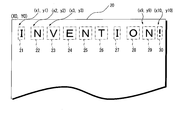
- FIG. 2 is an example of an imaged document image 20.
- the document image 20 includes characters (INVENTION!) Represented by the image. These characters are not represented by text data, but are represented by images. In this embodiment, the document image 20 is shaped.
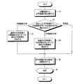
- FIG. 3 is a flowchart showing the processing procedure of the document image processing apparatus 1.
- step 31 processing such as extraction of a character image from the document image 20 is performed.
- FIG. 4 shows a state in which character images 21-30 are extracted from the document image 20.
- the extraction of the character image 21-30 uses the OCR function as described above.
- the extracted character image 21-30 is surrounded by a rectangle.
- the upper left vertex of the document image 20 is the origin (X0, Y0)
- the upper left coordinates of these rectangles are the coordinate positions of the character images 21-30.
- the positions of the character images 21, 22, and 23 are represented by coordinates (x1, y1), (x2, y2), and (x3, y3).
- the position of the character image 30 is represented by coordinates (x10, y10).
- the width and height of the character image 21-30 are also detected.
- the coordinates and the like of the detected character image 21-30 are stored in the character information table.
- FIG. 6 is an example of a character information table.
- the character information table shown in FIG. 6 is for the document image 20.
- the character information table stores, for each ID for identifying a detected character image, the X coordinate, Y coordinate, width, height, and character type represented by the character image. . ID1 to ID10 stored in the character information table correspond to character images 21 to 30, respectively.
- the ID of the character image 21 is ID1
- the X coordinate is x1
- the Y coordinate is y1
- the width is 0.5w
- the height is h
- the character type is “I”.
- the ID of the character image 30 is ID10
- the X coordinate is x10
- the Y coordinate is y10
- the width is 0.5w
- the height is h
- the character type is "!.
- a character image representing a forbidden character or a forbidden character is detected from the extracted character image (step 32).
- the beginning of a line prohibition character or the end of a line prohibition character is predetermined. For example, exclamation marks, question marks, commas, periods, end parentheses, etc. are forbidden characters, and opening parentheses are forbidden characters.
- a character image immediately before the bullet-inhibited character image and the bullet-inhibited character image are attached to generate a combined character image (step 33).
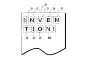
- FIG. 5 shows how a combined character image is generated.
- the character image 30 detected in the document image 20 shown in FIG. 4 represents a question mark, and is a forbidden character image 30.
- the character image 29 immediately before the forbidden character image 30 and the forbidden character image 30 are attached to generate one combined character image 30A.
- the character information table described above is also corrected.
- FIG. 7 shows an example of the corrected character information table.
- ID9 which is the ID of the character image 29 before combining is used. Since the combined character image 30A has character images 29 and 30 attached thereto, the width is changed from w to 1.5w, and the character type is changed from “N” to “N!”. The X coordinate, Y coordinate, and height are not changed.
- step 33 or 34 If neither the forbidden character image nor the forbidden character image is detected, the processing in step 33 or 34 is skipped.
- FIG. 8 shows a state in which the character image is positioned in the display area 50 corresponding to the desired display screen.
- the width of the display area 50 is narrower than the width of the document image 20. For this reason, in the document image 20, all of the character images 21 to 30 (30A) are displayed in one line, but all of the character images 21 to 30 (30A) are displayed in one line of the display area 50. I can't do it.
- the character images 21 to 25 are positioned, and in the second line of the display area 50, the character images 26 to 30A are positioned.
- the positioning of the character images 21 to 30A is performed using the character information table shown in FIG.
- the character image 26 protrudes from the display area 50, so that the character image 26 is placed at the head of the second line. It is positioned.
- the character image thus positioned in the display area 50 is displayed on the display screen 6 of the display device 5.
- FIG. 9 shows another example of the document image 40.
- the document image 40 includes character images 41 to 49. Although the character images 41 to 46 and 48 are not prohibited character images, the character image 47 is a forbidden character image 47 indicating the beginning of parentheses, and the character image 49 is a prohibited character image 49 indicating the end of parentheses.
- FIG. 10 shows a state where a combined character image is generated from the end-of-line prohibited character image 47 and the end-of-line prohibited character image 49.
- the combined character image when a combined character image is generated by combining a forbidden character image and a character image, the combined character image is positioned at the end of the line so that the combined character image does not fit in the display area. When it runs out, it reduces all the character images in the line to fit.
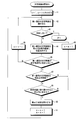
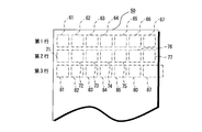
- FIG. 11 is a flowchart showing a character image positioning process procedure. The processing procedure of step 35 of FIG. 3 is shown. 12 and 13 show a state in which the character images 61 to 67, 71 to 77, 81 to 86, and the combined character image 87 are positioned in the display area 50. FIG.
- the number parameter n and the line parameter m are each reset to 1 (step 41).
- the nth character image is read out of the character images extracted as described above (NO in step 42 and step 43)
- the nth character image is positioned in the display area of the mth row.
- Step 44 For example, if it is the first character image, the character image is positioned at the first position on the first line, and the character image 61 is positioned as shown in FIG. If the nth character image fits in the display area 50 (NO in step 45), the number parameter n is incremented (step 46), and the processes of steps 42 and 44 are repeated again.
- the character images are sequentially positioned in the m-th line according to the character arrangement of the document image.
- nth character image does not fit in the display area (YES in step 45)
- nth character image that does not fit in the display area 50 is a combined character image (YES in step 47)
- all the character images in the mth line that do not fit in the display area 50 are reduced by a predetermined reduction ratio (for example, reduced by 90%). It is confirmed whether or not it can fit in the display area 50 when it is reduced at (rate) (step 48). If it does not fit (NO in step 48), the line parameter m is incremented (step 49) and the combined character image is positioned at the beginning of the next line (step 44). When it is within the range (YES in step 48), all the character images in the m-th line including the combined character image are reduced (step 50). For example, as shown in the third line of FIG.
- the combined character image 87 is positioned at the end of the third line, and the combined character image 87 protrudes from the display area 50, and the character images 81 to 86 in the third line.
- the combined character image 87 When it is determined that all of the combined character images 87 are reduced within the display area 50 by being reduced at a predetermined reduction rate, as shown in the third row of FIG. 86 and the combined character image 87 are reduced.
- the character images 81 to 86 and the combined character image 87 in the third line will fit in the display area 50. If all of the character images 81 to 86 and the combined character image 87 in the third line are reduced within the display area 50 even if they are reduced at a predetermined reduction ratio, the combined character image 87 is the first in the fourth line. Is positioned.
- processing for extracting a character image from the document image processing for determining whether the extracted character image is a prohibited character, processing for generating a combined character image, processing for creating a shaped image
- display processing on the display device 5 is performed.
- Data representing the created shaped image is transmitted from the document image processing device 1 to another terminal device such as a mobile phone, and the display processing is performed in the terminal device. It may be performed.
- the shaping image creation process may be performed in another terminal device.
- the processing in the document image processing apparatus 1 may be executed by software using a server instead of a dedicated apparatus, or may be executed by a mobile phone such as a smartphone.
- the horizontally written document image has been described.
- the embodiment can be similarly applied to a vertically written document image instead of horizontally written.
- vertical writing it may be read as a column instead of a row.
Landscapes
- Engineering & Computer Science (AREA)
- Theoretical Computer Science (AREA)
- Physics & Mathematics (AREA)
- General Physics & Mathematics (AREA)
- Health & Medical Sciences (AREA)
- Artificial Intelligence (AREA)
- Audiology, Speech & Language Pathology (AREA)
- Computational Linguistics (AREA)
- General Health & Medical Sciences (AREA)
- General Engineering & Computer Science (AREA)
- Computer Hardware Design (AREA)
- Processing Or Creating Images (AREA)
Description
この発明は,文書画像処理装置ならびにその動作制御方法およびその動作制御プログラムに関する。
文書画像や固定型レイアウトの文書ファイルを携帯端末で閲覧した場合,文書内の段落のサイズが携帯端末の表示画面サイズよりも大きいため,継続した閲覧には段落領域のスクロールを必要とする。このため携帯端末における文書閲覧では閲覧行為と端末操作行為とを交互に意識する必要があり,閲覧行為のみを継続することで得られる快適な文書閲覧ができなくなる。このような問題を解決するために「携帯端末向け文書画像レイアウト再構成技術「GT-Layout」の開発」(非特許文献1)が知られている。このGT-Layoutは,文書画像と文字位置情報とから,表示画面にあわせて文字位置を並べ替え,表示画面サイズに合った文書画像を構成することで一方向のスクロールにより文書の閲覧を可能にするものである。
文字画像の表示順番が決定され,その順番にしたがって文字画像が表示画面に表示される。文書画像ではない,テキスト・データによって表わされる通常の文章を画面に表示する場合,文章内の約物が行の先頭に来ないように,文字間のバランスを調整する禁則処理を行う必要がある。
また,句読点が後にくる場合には改行を認めないもの(特許文献1),句点については禁則処理により行頭に位置させることはできないとするもの(特許文献2),文字画像に禁則処理コードを付与するもの(特許文献3),文書画像についてのものではないが,禁則文字の場合,一文字前の文字に合成するもの(特許文献4)などもある。
http://www.fujifilm.co.jp/rd/report/rd057/pack/pdf/ff_rd057_009.pdf
http://ja.wikipedia.org/wiki/%E7%B4%84%E7%89%A9
特開平5-266168号公報
特開2004-280418号公報
特開2005-267129号公報
特開平6-236372号公報
しかしながら,禁則処理を行う場合であっても,文書画像の場合は文字が画像として表わされていることから,テキスト・データで表わされる文書の場合と同様の禁則処理を行うことはできない。たとえば,特許文献4では,禁則文字の場合,一文字前の文字領域の一部を切り取り,その切り取った部分に禁則文字を合成しているが,文字画像の一部が切
り取られてしまうと,文字を表わす画像部分も切り取られてしまう可能性がある。
り取られてしまうと,文字を表わす画像部分も切り取られてしまう可能性がある。
この発明は,文書画像において禁則処理ができるようにすることを目的とする。
この発明による文書画像処理装置は,文書が画像化された文書画像から,画像に含まれる文字を表わす文字画像を切り出す文字画像切り出し手段,画像切り出し手段において切り出された文字画像によって表わされる文字に行頭禁則文字または行末禁則文字が含まれているかどうかを判定する禁則文字判定手段,および禁則文字判定手段によって行頭禁則文字を表わす行頭禁則文字画像が含まれていると判定されたことに応じて行頭禁則文字画像を行頭禁則文字画像の直前の文字画像に結合して結合文字画像を生成し,禁則文字判定手段によって行末禁則文字を表わす行末禁則文字画像が含まれていると判定されたことに応じて行末禁則文字画像を行末禁則文字画像の直後の文字画像に結合して結合文字画像を生成する結合文字画像生成手段を備えていることを特徴とする。
この発明は,文書画像処理装置に適した動作制御方法も提供している。すなわち,この方法は,文字画像切り出し手段が,文書が画像化された文書画像から,画像に含まれる文字を表わす文字画像を切り出し,禁則文字判定手段が,画像切り出し手段において切り出された文字画像によって表わされる文字に行頭禁則文字または行末禁則文字が含まれているかどうかを判定し,結合文字画像生成手段が,禁則文字判定手段によって行頭禁則文字を表わす行頭禁則文字画像が含まれていると判定されたことに応じて行頭禁則文字画像を行頭禁則文字画像の直前の文字画像に結合して結合文字画像を生成し,禁則文字判定手段によって行末禁則文字を表わす行末禁則文字画像が含まれていると判定されたことに応じて行末禁則文字画像を行末禁則文字画像の直後の文字画像に結合して結合文字画像を生成するものである。
この発明によると,文書画像から文字画像が切り出され,切り出された文字画像によって表わされる文字に行頭禁則文字(行または列の先頭に現れる文字として適さない文字)または行末禁則文字(行または列の最後に現れる文字として適さない文字)が含まれているかどうかが判定される。行頭禁則文字が含まれている場合には,行頭禁則文字画像が,その直前の文字画像に結合され,結合文字画像が生成される。行末禁則文字画像が含まれている場合には,行末禁則文字画像が,その直後の文字画像に結合され,結合文字画像が生成される。行頭禁則文字画像または行末禁則文字画像単独では存在しないので,行頭または行末が行頭禁則文字画像または行末禁則文字画像となってしまうことを未然に防止できる。
文字画像切り出し手段において切り出された文字画像および結合文字画像生成手段によって生成された結合文字画像を文書画像における文字配列にしたがって表示画面の表示領域に位置決めする位置決め手段,行または列の最後の文字画像が結合文字画像であって,結合文字画像が表示領域に収まらないかどうかを判定する収納判定手段,ならびに収納判定手段によって結合文字画像が表示領域に収まらないと判定されたことに応じて,その結合文字画像が含まれる行または列のすべての文字画像を縮小する縮小手段をさらに備えるようにしてもよい。
縮小手段は,たとえば,所定の縮小率で,その結合文字画像が含まれる行または列の文字画像を縮小することにより結合文字画像の表示領域に収まらないかどうかを判定する縮小判定手段を備えてもよい。縮小判定手段により結合文字画像が表示領域に収まると判定されたことに応じて,その結合文字画像が含まれる行または列のすべての文字画像が縮小される。この場合,位置決め手段は,縮小判定手段により結合文字画像が表示領域に収まらないと判定されたことに応じて結合文字画像が最後に位置決めされていた行または列の次の行または列の先頭の位置に結合文字画像を位置決めすることが好ましい。
図1は,この発明の実施例を示すもので,文書画像(画像化された文書を文書画像ということにする)を,所望の表示領域に表示できるように整形する文書画像処理装置1の電気的構成を示すブロック図である。
文書画像処理装置1の全体の動作は,制御装置2によって統括される。
文書画像処理装置1には,種々の指令を入力するキーボードなどの入力装置3,他のクライアント端末装置,携帯電話などと通信するための通信装置4,文書画像等を表示する表示装置5,所定のデータを記憶するメモリ6などが設けられている。また,文書画像処理装置1には,CD(コンパクト・ディスク)ドライバ7が設けられている。後述する動作を制御するプログラムが格納されているコンパクト・ディスク8がCDドライバ7に装填され,コンパクト・ディスク8に格納されているプログラムがCDドライバ7によって読み取られると,そのプログラムが文書画像処理装置1にインストールされる。もっとも,通信装置4を利用してプログラムを受信し,受信したプログラムが文書画像処理装置1にインストールされるようにしてもよい。
さらに,文書画像処理装置1には,文字領域取得装置11,禁則文字抽出装置12,領域合成装置13および整形画像作成装置14が含まれている。文字領域取得装置11は,文書画像から文字画像の領域を検出して抽出するものである。文字画像の抽出は,OCR(Optical Character Reader)の機能を利用できる。文書画像における文字画像の座標位置,文字画像によって表わされる文字の種類,文字の並び順,文字が横書きか,縦書きかどうかも検出される。禁則文字抽出装置12は,文字画像によって表わされる文字が禁則文字の場合に,その文字画像を抽出するものである。文字領域取得装置11における文字の種類の検出は必ずしも精度が高くないので,ある文字画像の直前の文字画像および直後の文字画像のそれぞれの座標との相対的位置を参照して禁則文字を抽出することができる。たとえば,ダブル・クォーテーションと呼ばれる引用符は,その引用符の直前の文字画像によって表わされる文字の上部の10パーセント程度で正方形の形をした画像かどうかによって判定できる。もちろん,パターン・マッチングを利用して禁則文字を表わしている文字画像を抽出することもできる。領域合成装置13は,禁則文字を表わす文字画像を,その直前または直後の文字画像に結合して結合文字画像を生成するものである。禁則文字画像が行末禁則文字を表わしている場合には直後の文字画像と結合され,禁則文字画像が行頭禁則文字を表わしている場合には直前の文字画像と結合される。整形画像作成装置14は,所望の表示領域をもつ表示画面に表示できるように,文字領域取得装置11において得られた文字画像および領域合成装置13において得られた結合文字画像の位置決めをするものである。これらの処理について詳しくは,後述する。
図2は,画像化された文書画像20の一例である。
文書画像20には,画像によって表わされている文字(INVENTION!)が含まれている。これらの文字は,テキスト・データによって表わされているものではなく,画像によって表わされているものである。この実施例では,この文書画像20が整形される。
図3は,文書画像処理装置1の処理手順を示すフローチャートである。
メモリ6には,文書画像20を表わす文書画像データが格納されているものとする。図2に示したように,文書画像20から,文字画像の抽出等の処理が行われる(ステップ31)。
図4は,文書画像20から,文字画像21-30が抽出された様子を示している。文字画像21-30の抽出は,上述のようにOCRの機能が利用される。抽出された文字画像21-30は,矩形で囲まれている。文書画像20の左上の頂点を原点(X0,Y0)としたときに,これらの矩形の左上の座標が,文字画像21-30の座標位置となる。たとえば,文字画像21,22および23のそれぞれの位置は,座標(x1,y1),(x2,y2)および(x3,y3)で表わされる。同様に,文字画像30の位置は,座標(x10,y10)で表わされる。また,文字画像21-30の幅および高さも検出される。検出された文字画像21-30の座標等は,文字情報テーブルに格納される。
図6は,文字情報テーブルの一例である。
図6に示す文字情報テーブルは,文書画像20についてのものである。
文字情報テーブルには,検出された文字画像を識別するためのIDごとに,文字画像のX座標,Y座標,幅,高さおよび文字画像によって表わされている文字の種類が格納されている。文字情報テーブルに格納されているID1からID10は,文字画像21から30にそれぞれ対応している。たとえば,文字画像21のIDは,ID1であり,X座標はx1,Y座標はy1,幅は0.5w,高さはh,文字の種類は「I」である。また,文字画像30のIDは,ID10であり,X座標はx10,Y座標はy10,幅は0.5w,高さはh,文字の種類は「!」である。
図3に戻って,抽出した文字画像から行頭禁則文字または行末禁則文字を表す文字画像が検出されたかどうかが確認される(ステップ32)。行頭禁則文字または行末禁則文字はあらかじめ決められている。たとえば,感嘆符,疑問符,カンマ,ピリオド,終わりの括弧などが行頭禁則文字であり,始まりの括弧などが行末禁則文字である。
行頭禁則文字を表す行頭禁則文字画像が検出された場合には,その行頭禁則文字画像の直前の文字画像と,その行頭禁則文字画像とが付けられて,結合文字画像が生成される(ステップ33)。
図5は,結合文字画像が生成される様子を示している。
図4に示す文書画像20において検出された文字画像30は疑問符を表しており,行頭禁則文字画像30である。このために,行頭禁則文字画像30の直前の文字画像29と行頭禁則文字画像30とが付けられて一つの結合文字画像30Aが生成される。結合文字画像30Aが生成されると,上述した文字情報テーブルも修正される。
図7は,修正後の文字情報テーブルの一例である。
上述のように生成された結合文字画像30AのIDは,結合前の文字画像29のIDであるID9が用いられている。結合文字画像30Aは,文字画像29と30とが付けられたものであるから,幅がwから1.5wに変更され,文字の種類が「N」から「N!」に変更されている。X座標,Y座標および高さについては変更されていない。
図3に戻って,行末禁則文字を表す行末禁則文字画像が検出された場合には,その行末禁則文字画像の直後の文字画像と,その行末禁則文字画像とが結合されて,結合文字画像が生成される(ステップ34)。行末禁則文字画像の結合処理については後述する(図9,図10参照)。
行頭禁則文字画像および行末禁則文字画像のいずれも検出されない場合にはステップ33または34の処理はスキップされる。
行頭禁則文字画像または行末禁則文字画像が検出され,結合文字画像が生成される,あるいは行頭禁則文字画像および行末禁則文字画像のいずれも検出されないと,検出された文字画像等が,表示しようとする表示画面の表示領域に位置決めされる(ステップ35)。これにより整形画像の作成処理が行われることとなる。
図8は,所望の表示画面に対応する表示領域50に文字画像が位置決めされた様子を示している。
表示領域50の横幅は,文書画像20の横幅よりも狭い。このために,文書画像20では1行に文字画像21から30(30A)のすべてが表示されているが,表示領域50の1行にはそれらの文字画像21から30(30A)のすべてを表示することはできない。
表示領域50の第1行目には文字画像21から25が位置決めされ,表示領域50の第2行目には文字画像26から30Aが位置決めされている。文字画像21から30Aの位置決めは,図7に示す文字情報テーブルを利用して,文書画像2の文字配列どおりに表示領域50に収まるように行われるのはいうまでもない。たとえば,図8に示す例では,文字画像21から26までを第1行に収めようとすると,文字画像26が表示領域50からはみ出してしまうので,その文字画像26は第2行目の先頭に位置決めされている。
このようにして表示領域50内に位置決めされた文字画像が表示装置5の表示画面6に表示されることとなる。
図9は,文書画像40の他の例を示している。
文書画像40には,文字画像41から49が含まれている。文字画像41から46および48は禁則文字画像ではないが,文字画像47は括弧の始まりを示す行末禁則文字画像47であり,文字画像49は括弧の終わりを示す行頭禁則文字画像49である。
図10は,行末禁則文字画像47および行頭禁則文字画像49から結合文字画像が生成される様子を示している。
上述したように,行末禁則文字画像47の場合には,その直後にある文字画像48と結合される。また行頭禁則文字画像49の場合には,その直前にある文字画像48と結合される。これにより,結合文字画像49Aが得られる。
図11から図13は,他の実施例を示している。
この実施例は,上述のように行頭禁則文字画像と文字画像とが結合されて結合文字画像が生成された場合に,その結合文字画像が行の最後に位置決めされることにより表示領域内に収まらなくなるときに,収まるように行のすべての文字画像を縮小するものである。
図11は,文字画像位置決め処理手順を示すフローチャートである。図3のステップ35の処理手順を示している。図12および図13は,表示領域50に文字画像61から67,71から77,81から86および結合文字画像87が位置決めされている様子を示している。
まず,番号パラメータnおよび行パラメータmがそれぞれ1にリセットされる(ステップ41)。上述のようにして抽出された文字画像のうち第n番目の文字画像が読み取られると(ステップ42,ステップ43でNO),その第n番目の文字画像が第m行の表示領域に位置決めされる(ステップ44)。たとえば,最初の文字画像であれば,その文字画像が第1行目の最初の位置に位置決めされ,図12に示すように文字画像61が位置決めされる。第n番目の文字画像が表示領域50に収まれば(ステップ45でNO),番号パラメータnがインクレメントされ(ステップ46),再びステップ42および44の処理が繰り返される。これにより第m行に文書画像の文字配列にしたがって文字画像が順次位置決めされていく。
第n番目の文字画像が表示領域に収まらなくなると(ステップ45でYES),その第n番目の文字画像が結合文字画像かどうかが判定される(ステップ47)。結合文字画像でなければ(ステップ47でNO),行パラメータmがインクレメントされ(ステップ49),第n番目の文字画像が第m行の表示領域50に位置決めされる(ステップ44)。たとえば,図12に示すように,第1行に文字画像61から67が位置決めされ,次に読み取られた文字画像71が第1行に位置決めしようとすると表示領域50内に入らない。文字画像71は結合文字画像ではないので,第2行目の最初に位置決めされることとなる。
表示領域50に収まらなくなった第n番目の文字画像が結合文字画像であると(ステップ47でYES),収まらなくなった第m行のすべての文字画像を所定の縮小率(たとえば,90パーセントの縮小率)で縮小した場合に表示領域50に収まるかどうかが確認される(ステップ48)。収まらなければ(ステップ48でNO),行パラメータmがインクレメントされ(ステップ49),結合文字画像は次の行の先頭に位置決めされる(ステップ44)。収まると(ステップ48でYES),結合文字画像を含めて第m行のすべての文字画像が縮小される(ステップ50)。たとえば,図12の第3行に示すように,第3行の最後に結合文字画像87が位置決めされ,その結合文字画像87が表示領域50からはみ出しており,第3行の文字画像81から86および結合文字画像87のすべてが所定の縮小率で縮小させられることにより,表示領域50内に収まると判断されると,図13の第3行に示すように,第3行の文字画像81から86および結合文字画像87が縮小させられる。第3行の文字画像81から86および結合文字画像87が表示領域50内に収まることとなる。第3行の文字画像81から86および結合文字画像87のすべてが所定の縮小率で縮小させられても,表示領域50内に収まらない場合には,結合文字画像87は第4行目の最初に位置決めされる。
上述の実施例では,文書画像処理装置1において,文書画像から文字画像を抽出する処理,抽出した文字画像が禁則文字かどうかを判定する処理,結合文字画像を生成する処理,整形画像の作成処理および表示装置5への表示処理が行われているが,作成された整形画像を表わすデータを文書画像処理装置1から,携帯電話などの他の端末装置に送信し,その端末装置において表示処理が行われるようにしてもよい。また,整形画像の作成処理も他の端末装置において行われるようにしてもよい。さらに,文書画像処理装置1における処理は,専用装置でなく,サーバを利用したソフトウエアによって実行するようにしてもよいし,スマートフォンのような携帯電話において実行するようにしてもよい。
さらに,上述の実施例では,横書きの文書画像について説明したが,横書きでなく,縦書きの文書画像についても同様に実施できる。縦書きの場合,行の変わりに列と読み替えればよいこととなろう。
1 文書画像処理装置
2 制御装置
11 文字領域取得装置
12 禁則文字抽出装置
13 領域合成装置
14 整形画像作成装置
20,40 文書画像
2 制御装置
11 文字領域取得装置
12 禁則文字抽出装置
13 領域合成装置
14 整形画像作成装置
20,40 文書画像
Claims (5)
- 文書が画像化された文書画像から,画像に含まれる文字を表わす文字画像を切り出す文字画像切り出し手段,
上記画像切り出し手段において切り出された文字画像によって表わされる文字に行頭禁則文字または行末禁則文字が含まれているかどうかを判定する禁則文字判定手段,および
上記禁則文字判定手段によって行頭禁則文字を表わす行頭禁則文字画像が含まれていると判定されたことに応じて行頭禁則文字画像を行頭禁則文字画像の直前の文字画像に結合して結合文字画像を生成し,上記禁則文字判定手段によって行末禁則文字を表わす行末禁則文字画像が含まれていると判定されたことに応じて行末禁則文字画像を行末禁則文字画像の直後の文字画像に結合して結合文字画像を生成する結合文字画像生成手段,
を備えた文書画像処理装置。 - 上記文字画像切り出し手段において切り出された文字画像および上記結合文字画像生成手段によって生成された結合文字画像を文書画像における文字配列にしたがって表示画面の表示領域に位置決めする位置決め手段,
行または列の最後の文字画像が結合文字画像であって,結合文字画像が表示領域に収まらないかどうかを判定する収納判定手段,ならびに
上記収納判定手段によって結合文字画像が表示領域に収まらないと判定されたことに応じて,その結合文字画像が含まれる行または列のすべての文字画像を縮小する縮小手段,
を備えた請求項1に記載の文書画像処理装置。 - 上記縮小手段は,
所定の縮小率で,その結合文字画像が含まれる行または列の文字画像を縮小することにより結合文字画像の表示領域に収まらないかどうかを判定する縮小判定手段を備え,
上記縮小判定手段により結合文字画像が表示領域に収まると判定されたことに応じて,その結合文字画像が含まれる行または列のすべての文字画像を縮小するものであり,
上記位置決め手段は,
上記縮小判定手段により結合文字画像が表示領域に収まらないと判定されたことに応じて結合文字画像が最後に位置決めされていた行または列の次の行または列の先頭の位置に結合文字画像を位置決めするものである,
請求項1または2に記載の文書画像処理装置。 - 文字画像切り出し手段が,文書が画像化された文書画像から,画像に含まれる文字を表わす文字画像を切り出し,
禁則文字判定手段が,上記画像切り出し手段において切り出された文字画像によって表わされる文字に行頭禁則文字または行末禁則文字が含まれているかどうかを判定し,
結合文字画像生成手段が,上記禁則文字判定手段によって行頭禁則文字を表わす行頭禁則文字画像が含まれていると判定されたことに応じて行頭禁則文字画像を行頭禁則文字画像の直前の文字画像に結合して結合文字画像を生成し,上記禁則文字判定手段によって行末禁則文字を表わす行末禁則文字画像が含まれていると判定されたことに応じて行末禁則文字画像を行末禁則文字画像の直後の文字画像に結合して結合文字画像を生成する,
文書画像処理装置の動作制御方法。 - 文書画像処理装置のコンピュータを制御するコンピュータが読み取り可能なプログラムであって,
文書が画像化された文書画像から,画像に含まれる文字を表わす文字画像を切り出させ,
切り出された文字画像によって表わされる文字に行頭禁則文字または行末禁則文字が含まれているかどうかを判定させ,
行頭禁則文字を表わす行頭禁則文字画像が含まれていると判定されたことに応じて行頭禁則文字画像を行頭禁則文字画像の直前の文字画像に結合して結合文字画像を生成させ,
行末禁則文字を表わす行末禁則文字画像が含まれていると判定されたことに応じて行末禁則文字画像を行末禁則文字画像の直後の文字画像に結合して結合文字画像を生成させるように文書画像処理装置のコンピュータを制御するプログラム。
Applications Claiming Priority (2)
| Application Number | Priority Date | Filing Date | Title |
|---|---|---|---|
| JP2012211631 | 2012-09-26 | ||
| JP2012-211631 | 2012-09-26 |
Publications (1)
| Publication Number | Publication Date |
|---|---|
| WO2014050480A1 true WO2014050480A1 (ja) | 2014-04-03 |
Family
ID=50387888
Family Applications (1)
| Application Number | Title | Priority Date | Filing Date |
|---|---|---|---|
| PCT/JP2013/073885 Ceased WO2014050480A1 (ja) | 2012-09-26 | 2013-09-05 | 文書画像処理装置ならびにその動作制御方法およびその動作制御プログラム |
Country Status (1)
| Country | Link |
|---|---|
| WO (1) | WO2014050480A1 (ja) |
Citations (3)
| Publication number | Priority date | Publication date | Assignee | Title |
|---|---|---|---|---|
| JPH05266168A (ja) * | 1992-03-17 | 1993-10-15 | Fuji Xerox Co Ltd | 文書処理装置 |
| JPH06236372A (ja) * | 1993-02-10 | 1994-08-23 | Matsushita Electric Ind Co Ltd | 文字表示装置 |
| JPH071763A (ja) * | 1994-02-14 | 1995-01-06 | Hitachi Ltd | 行末の印字揃えを行なう印刷制御方法 |
-
2013
- 2013-09-05 WO PCT/JP2013/073885 patent/WO2014050480A1/ja not_active Ceased
Patent Citations (3)
| Publication number | Priority date | Publication date | Assignee | Title |
|---|---|---|---|---|
| JPH05266168A (ja) * | 1992-03-17 | 1993-10-15 | Fuji Xerox Co Ltd | 文書処理装置 |
| JPH06236372A (ja) * | 1993-02-10 | 1994-08-23 | Matsushita Electric Ind Co Ltd | 文字表示装置 |
| JPH071763A (ja) * | 1994-02-14 | 1995-01-06 | Hitachi Ltd | 行末の印字揃えを行なう印刷制御方法 |
Similar Documents
| Publication | Publication Date | Title |
|---|---|---|
| US20110221766A1 (en) | Method for printing a captured screen of web pages | |
| US20120096343A1 (en) | Systems, methods, and computer-readable media for providing a dynamic loupe for displayed information | |
| EP2874054B1 (en) | Application text adjusting method, device, and terminal | |
| JP5654851B2 (ja) | 文書画像表示装置ならびにその動作制御方法およびその制御プログラム | |
| JP2008158765A (ja) | 情報処理装置、情報処理方法、及び、当該情報処理方法をコンピュータに実行させるためのプログラム | |
| JP2005044279A (ja) | 帳票処理方法、帳票処理プログラム、帳票処理装置 | |
| JP4776995B2 (ja) | コンピュータ装置およびその制御方法およびプログラム | |
| JP2014182588A (ja) | 情報端末、操作領域制御方法及び操作領域制御プログラム | |
| JP2013125426A (ja) | コンテンツ表示装置、方法及びプログラム | |
| CN110727481A (zh) | 图片编辑方法、装置、计算机设备和存储介质 | |
| JP2008234147A (ja) | 文書画像表示装置、文書画像表示方法及び文書画像表示プログラム | |
| JP2008040703A (ja) | 共有画像表示プログラム、情報端末装置 | |
| US9692936B2 (en) | Image processing apparatus and image processing method for clipping, from a second image, an area at a position corresponding to designated position in a first image | |
| WO2014050480A1 (ja) | 文書画像処理装置ならびにその動作制御方法およびその動作制御プログラム | |
| KR100686162B1 (ko) | 이동통신 단말기 및 섬네일 이미지 표시 방법 | |
| JP4305325B2 (ja) | 付箋情報処理方法、付箋情報処理システム及び付箋情報処理プログラム | |
| KR101935926B1 (ko) | 웹툰 편집 서버 및 그 방법 | |
| JP5482710B2 (ja) | 表示端末装置及びプログラム | |
| WO2014050481A1 (ja) | 文書画像処理装置ならびにその動作制御方法およびその動作制御プログラム | |
| US8707165B2 (en) | Information processing apparatus, control method, and storage medium for adjustment of alternate document layers to reduce printed pages | |
| JP6146222B2 (ja) | 手書き入力装置およびプログラム | |
| JP2013088777A (ja) | ビューワ装置、サーバ装置、表示制御方法、電子コミック編集方法及びプログラム | |
| JP2012093888A (ja) | 文書画像表示装置ならびにその動作制御方法およびその動作プログラム | |
| JP2009169548A (ja) | 情報処理装置、そのマルチウィンドウ表示方法及びプログラム | |
| JP3991061B1 (ja) | 画像処理システム |
Legal Events
| Date | Code | Title | Description |
|---|---|---|---|
| 121 | Ep: the epo has been informed by wipo that ep was designated in this application |
Ref document number: 13843019 Country of ref document: EP Kind code of ref document: A1 |
|
| NENP | Non-entry into the national phase |
Ref country code: DE |
|
| 122 | Ep: pct application non-entry in european phase |
Ref document number: 13843019 Country of ref document: EP Kind code of ref document: A1 |
|
| NENP | Non-entry into the national phase |
Ref country code: JP |