WO2014050203A1 - タイヤ組付体のバランス修正方法 - Google Patents
タイヤ組付体のバランス修正方法 Download PDFInfo
- Publication number
- WO2014050203A1 WO2014050203A1 PCT/JP2013/063922 JP2013063922W WO2014050203A1 WO 2014050203 A1 WO2014050203 A1 WO 2014050203A1 JP 2013063922 W JP2013063922 W JP 2013063922W WO 2014050203 A1 WO2014050203 A1 WO 2014050203A1
- Authority
- WO
- WIPO (PCT)
- Prior art keywords
- unbalance
- amount
- correction
- dynamic
- static
- Prior art date
- Legal status (The legal status is an assumption and is not a legal conclusion. Google has not performed a legal analysis and makes no representation as to the accuracy of the status listed.)
- Ceased
Links
Images



Classifications
-
- G—PHYSICS
- G01—MEASURING; TESTING
- G01M—TESTING STATIC OR DYNAMIC BALANCE OF MACHINES OR STRUCTURES; TESTING OF STRUCTURES OR APPARATUS, NOT OTHERWISE PROVIDED FOR
- G01M1/00—Testing static or dynamic balance of machines or structures
- G01M1/30—Compensating imbalance
- G01M1/32—Compensating imbalance by adding material to the body to be tested, e.g. by correcting-weights
Definitions
- the present invention relates to a balance correction method for a tire assembly (tire assembly) in which a tire is assembled to a wheel.
- the tire assembly in which the tire is assembled to the wheel has an unbalance caused by a tire manufacturing error and a wheel manufacturing error.
- This unbalance is divided into a static unbalance that exists without rotating the tire and a dynamic unbalance that occurs only when the tire is rotated.
- Static imbalance occurs when the weight distribution in the circumferential direction of the tire assembly is not uniform, and dynamic unbalance is heavy when parts with different weights are separated in the axial direction of the tire assembly. This occurs due to the fact that a large centrifugal force acts on the location and a couple is generated by this centrifugal force.
- Patent Document 1 To correct the static imbalance and dynamic unbalance, the static imbalance and dynamic unbalance are corrected simultaneously by attaching one balance weight to each of the front and back rim flanges (two in total). Was. However, since this is not sufficient, Patent Document 1 is proposed.
- Patent Document 1 first, a static unbalance correction amount and a dynamic unbalance correction amount are simultaneously measured by a measuring device, and thereafter, the static unbalance correction amount and the dynamic unbalance correction amount are separately corrected. That is, a balance weight corresponding to the static unbalance correction amount is fixed to a position where the residual dynamic imbalance correction amount is minimized, and then a balance weight corresponding to the residual dynamic imbalance correction amount is fixed to the calculated position.
- a balance weight corresponding to the static unbalance correction amount is fixed to a position where the residual dynamic imbalance correction amount is minimized, and then a balance weight corresponding to the residual dynamic imbalance correction amount is fixed to the calculated position.
- Static unbalance causes vertical vibrations of the vehicle body, and dynamic unbalance causes a handle shimmy, that is, a phenomenon in which the handle vibrates in small increments.
- static unbalance is corrected, but correction of static unbalance does not necessarily lead to correction of dynamic unbalance. For this reason, dynamic imbalance remains and the above-mentioned handle shimmy cannot be effectively prevented.
- a method for correcting the balance of a tire assembly first determines the correction amount and the correction position of static unbalance and dynamic unbalance of a tire assembly in which a tire is assembled to a wheel.
- the dynamic unbalance correction amount and the correction position obtained as a result of the measurement are used to determine the dynamic unbalance.
- the dynamic unbalance correction amount on the inner side of the tire assembly is compared with the dynamic unbalance correction amount on the outer side.
- the static unbalance is corrected based on the correction amount and the correction position of the static unbalance.
- 40g is appropriate as the threshold value of the dynamic unbalance amount. It has been clarified from running tests on many tire assemblies that when the amount of dynamic imbalance inside or outside the tire assembly exceeds 20 g, the ride quality of the automobile deteriorates. Therefore, it is preferable that the threshold value is 40 g which is the maximum value when either the inner side or the outer side exceeds 20 g.
- the static unbalance amount is less than 7 g, the static unbalance amount is small. Therefore, when the dynamic unbalance amount is 40 g or more, only the dynamic unbalance amount is corrected without correcting the static unbalance amount. When the balance amount is less than 40 g, it is preferable not to perform unbalance correction.
- handling shimmy caused by dynamic imbalance can be reliably eliminated, and the balance weight need not be attached to the outside of the rim, so that the appearance of the automobile is also improved.
- FIG. 2 is a graph showing the results of a steering vibration test performed on the tire assembly in the states (1) to (5) in FIG. The flowchart explaining the balance correction method which concerns on this invention
- the tire assembly 1 is configured by assembling a tire 3 on the outer side of a wheel 2, an inner rim 4 is formed on the inner side of the wheel 2, and an outer rim 5 is formed on the outer side.
- a balance weight is attached to the inner rim 4 or the outer rim 5.
- the balance measuring apparatus 10 has load cells 14 and 15 comprising acceleration sensors attached to an upper plate 12 and a lower plate 13 of a spindle shaft 11 that are rotated by a drive source (not shown), and the tire assembly 1 is fixed on the upper plate 12. Then, the output from the load cells 14 and 15 at the time of rotation is processed by the calculation device 16 to calculate the static unbalance amount and the dynamic unbalance amount of the tire assembly 1, and the calculated values are displayed on the display 17. Is configured to be displayed.
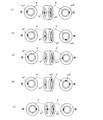
- FIGS. 2 (1) to (5) are views showing a state where a balance weight is attached to a tire assembly that has been adjusted for balance
- FIG. 3 is a tire in the state of (1) to (5) in FIG. It is a graph which shows the result of the steering vibration test performed with respect to the assembly.
- balance weights W1 and W2 are attached to the front portions (in the same phase) of the inner rim 4 and the outer rim 5 of the tire assembly 1 that has already been balanced. Since the balance weight is attached to the same phase in both cases, the amount of static unbalance is large (unstable).
- balance weights W1 and W2 are attached to the rear portions (in the same phase) of the inner rim 4 and the outer rim 5, respectively. Therefore, the static unbalance amount is large as in (1).
- balance weight W1 attached to the front portion of the inner rim 4 and a balance weight W2 attached to the rear portion of the outer rim 5. That is, since the phase is shifted by 180 °, the amount of static unbalance is small.
- the balance weights W1 and W2 are out of phase by 90 °. Accordingly, the static unbalance amount is intermediate between (1), (5) and (3).
- FIG. 3 shows that the handle shimmy increases in proportion to the amount of static unbalance. That is, it can be said that if the static unbalance of the tire assembly 1 is corrected and made smaller, it is effective in reducing steering shimmy.
- FIG. 4 is a flowchart of the method of the present invention based on the above findings.
- an unbalance amount of the tire assembly is measured by a measuring device. Then, it is determined whether or not the dynamic unbalance amount among the unbalance amounts is equal to or greater than a threshold value of 40 g. As described above, this threshold value is a numerical value that deteriorates the ride comfort of the automobile as a result of a running test for many tire assemblies.
- the dynamic unbalance amount is 40 g or more, it is next determined whether or not the static unbalance amount is 7 g or more.
- the static unbalance amount is 7 g or more, both the dynamic unbalance and the static unbalance are corrected. If the static unbalance amount is less than 7 g, the dynamic unbalance is corrected.
- 7 g of the static unbalance amount is a numerical value obtained inductively as a result of running tests on a large number of tire assemblies with different static unbalance amounts.
- the dynamic unbalance amount is less than 40 g, it is next determined whether or not the static unbalance amount is 7 g or more. When the amount of static unbalance is less than 7 g, neither dynamic unbalance nor static unbalance is corrected. This is because it is determined that the correction has already been sufficiently made.
- the balance correction method according to the present invention can be used to correct the balance of a tire assembly using an existing measuring device.
Landscapes
- Physics & Mathematics (AREA)
- General Physics & Mathematics (AREA)
- Testing Of Balance (AREA)
Description
本発明は、タイヤをホイールに組み付けたタイヤ組付体(タイヤアッシー)のバランス修正方法に関する。
タイヤをホイールに組み付けたタイヤ組付体にはタイヤの製造誤差及びホイールの製造誤差に起因するアンバランスが存在する。このアンバランスはタイヤを回転させないでも存在する静アンバランスとタイヤを回転させて初めて発生する動アンバランスに分けられる。
静アンバランスはタイヤ組付体の円周方向の重量配分が不均一な場合に発生し、動アンバランスはタイヤ組付体の軸方向に重さの異なる箇所が離間して存在する場合に重い箇所に大きな遠心力が作用し、この遠心力によって偶力が生じることに起因して発生する。
上記の静アンバランスと動アンバランスを修正するには、従来から表裏リムフランジの1箇所(合計2箇所)に各々1個づつバランスウェイトを固着することで静アンバランスと動アンバランスを同時に修正していた。しかしながら、これでは十分でないため、特許文献1が提案されている。
特許文献1では、先ず測定装置によって静アンバランス修正量と動アンバランス修正量とを同時に測定し、その後、静アンバランス修正量と動アンバランス修正量とを別々に修正する。即ち、残留動アンバランス修正量が最小となる位置に、静アンバランス修正量に相当するバランスウェイトを固着し、次いで演算された位置に残留動アンバランス修正量に相当するバランスウェイトを固着することが提案されている。
静アンバランスは車体の上下振動の原因となり、動アンバランスはハンドルシミー即ちハンドルが小刻みに振動する現象を引き起こす。
上述した特許文献1に開示される方法では、静アンバランスを修正しているが、静アンバランスの修正は必ずしも動アンバランスの修正にはつながらない。このため、動アンバランスが残り、上記のハンドルシミーを効果的に防止することができない。
上述した特許文献1に開示される方法では、静アンバランスを修正しているが、静アンバランスの修正は必ずしも動アンバランスの修正にはつながらない。このため、動アンバランスが残り、上記のハンドルシミーを効果的に防止することができない。
上記従来の課題を解決するため、本発明に係るタイヤ組付体のバランス修正方法は、先ず、ホイールにタイヤを組み付けたタイヤ組付体の静アンバランス及び動アンバランスの修正量及び修正位置を測定装置によって測定し、この測定の結果得られた動アンバランス量が予め設定した閾値以上の場合には、測定の結果得られた動アンバランスの修正量と修正位置に基づいて動アンバランスの修正を行い、動アンバランス量が予め設定した閾値未満の場合には、タイヤ組付体の内側における動アンバランス修正量と外側における動アンバランス修正量とを比較し、修正量の大きい側に静アンバランスの修正量と修正位置に基づき静アンバランスの修正を行う。
前記動アンバランス量の閾値としては40gが適当である。タイヤ組付体の内側または外側の動アンバランス量が20gを超えると、自動車の乗り心地が悪化することが多くのタイヤ組付体についての走行テストから明らかになっている。そこで、内側と外側の何れかが20gを超えた場合の最大値である40gを閾値とすることが好ましい。
また、静アンバランス量が7g未満の場合は、静アンバランス量として小さいため、動アンバランス量が40g以上の場合は静アンバランス量を修正せずに動アンバランス量のみ修正し、動アンバランス量が40g未満の場合はアンバランス修正を行わないことが好ましい。
本発明によれば、動アンバランスに起因するハンドリングシミーを確実に解消することができ、しかもバランスウェイトをリム外側に取付けずに済むため、自動車の外観性も向上する。
以下に本発明の実施例を添付図面に基づいて説明する。
先ず、図1に基づいてタイヤ組付体とそのバランス測定装置について説明する。タイヤ組付体1はホイール2の外側にタイヤ3を組み付けて構成され、ホイール2の内側には内側リム4が形成され、外側には外側リム5が形成されている。そして、通常、内側リム4または外側リム5にバランスウェイトが取り付けられる。
先ず、図1に基づいてタイヤ組付体とそのバランス測定装置について説明する。タイヤ組付体1はホイール2の外側にタイヤ3を組み付けて構成され、ホイール2の内側には内側リム4が形成され、外側には外側リム5が形成されている。そして、通常、内側リム4または外側リム5にバランスウェイトが取り付けられる。
バランス測定装置10は、図示しない駆動源によって回転せしめられるスピンドルシャフト11の上部プレート12と下部プレート13に加速度センサからなるロードセル14,15を取付け、上部プレート12上に前記タイヤ組付体1を固定して回転させた際のロードセル14,15からの出力を演算装置16で演算処理することで、タイヤ組付体1の静アンバランス量と動アンバランス量を算出し、この算出値をディスプレイ17に表示する構成になっている。
図2(1)~(5)はバランス調整済みのタイヤ組付体に位置を変えてバランスウェイトを取付けた状態を示す図、図3は図2の(1)~(5)の状態のタイヤ組付体に対して行ったステアリング振動試験の結果を示すグラフである。
図2(1)は既にバランス調整が済んでいるタイヤ組付体1の内側リム4及び外側リム5の前部分(同位相)に各々30gのバランスウェイトW1、W2を取付けている。共に同じ位相にバランスウェイトが取付けられているので、静アンバランス量は大きく(不安定)なっている。
同様に、図2(5)に示すタイヤ組付体1は、内側リム4及び外側リム5の後部分(同位相)に各々30gのバランスウェイトW1、W2を取付けている。したがって、(1)と同様に静アンバランス量は大きくなっている。
図2(3)に示すタイヤ組付体1は、内側リム4の前部分にバランスウェイトW1を、外側リム5の後部分にバランスウェイトW2を取付けている。即ち位相が180°ずれているので静アンバランス量は小さくなっている。
また、図2(2)及び(4)に示すタイヤ組付体1は、バランスウェイトW1、W2の位相が90°ずれている。したがって、静アンバランス量は(1)(5)と(3)の中間となる。
一方、図3からは静アンバランス量の大きさに比例してハンドルシミーが大きくなることが分かる。即ち、タイヤ組付体1の静アンバランスを修正して小さくすれば、ハンドルシミーの低減に有効であると言える。
図4は上記の知見に基づいた本発明方法のフローチャートである。
本発明方法では、先ず測定装置によってタイヤ組付体のアンバランス量を測定する。
そしてアンバランス量のうち動アンバランス量が40gの閾値以上であるか否かを判断する。この閾値は前記したように多くのタイヤ組付体についての走行テストの結果として、自動車の乗り心地が悪化する数値である。
本発明方法では、先ず測定装置によってタイヤ組付体のアンバランス量を測定する。
そしてアンバランス量のうち動アンバランス量が40gの閾値以上であるか否かを判断する。この閾値は前記したように多くのタイヤ組付体についての走行テストの結果として、自動車の乗り心地が悪化する数値である。
動アンバランス量が40g以上の場合は、次に静アンバランス量が7g以上か否かを判断する。静アンバランス量が7g以上の場合は動アンバランスと静アンバランスの両方を修正する。また静アンバランス量が7g未満の場合は動アンバランスを修正する。
ここで、静アンバランス量の7gは静アンバランス量が異なる多数のタイヤ組付体について走行テストを行った結果、帰納的に得られた数値である。
ここで、静アンバランス量の7gは静アンバランス量が異なる多数のタイヤ組付体について走行テストを行った結果、帰納的に得られた数値である。
また、動アンバランス量が40g未満の場合は、次に静アンバランス量が7g以上か否かを判断する。静アンバランス量が7g未満の場合は動アンバランス及び静アンバランスの何れも修正しない。これは、既に十分修正されていると判断されるからである。
一方、動アンバランス量が40g未満で静アンバランス量が7g以上の場合には、外側の動アンバランス量と内側の動アンバランス量のどちらが大きいかを判断し、大きい側の静アンバランス量を修正する。
以上の手順で修正した例を(表1)に示す。
以上の手順で修正した例を(表1)に示す。

(表1)において、実験例1、9~13、20-1、21-1、22-1、23-1、24-1及び25-1については内側の動アンバランスと外側の動アンバランスを比較し、アンバランス量が大きい側のリムについて静アンバランスの修正を行った。その結果、残留アンバランス量が減少し、ハンドルシミーを確実に低減させることができる。
これに対し、実験例20-2、21-2、22-2、23-2、24-2及び25-2ではアンバランス量が小さい側のリムについて静アンバランスの修正を行った。この場合には、残留動アンバランス量が増加し、ハンドルシミーの低減には寄与しない。
また実験例14、15、17~19に示すように、動アンバランスの大きさが40gの場合にアンバランス量が大きい側のリムについて静アンバランスの修正を行ったところ、修正後の再アンバランステストによる残留アンバランス量は内側または外側の何れかに20g以上の動アンバランスが残留することが確認された。この場合には、動アンバランスの修正を行うことで、静アンバランスも低減されるので、車体の振動及びハンドルシミーの低減が図れる。
本発明に係るバランス修正方法は既存の測定装置を用いて、タイヤ組付体のバランス修正に利用することができる。
1…タイヤ組付体、2…ホイール、3…タイヤ、4…内側リム、5…外側リム、10…バランス測定装置、11…スピンドルシャフト、12…上部プレート、13…下部プレート、14,15…ロードセル、16…演算装置、17…ディスプレイ、W1,W2…バランスウェイト。
Claims (3)
- ホイールにタイヤを組み付けたタイヤ組付体の静アンバランス及び動アンバランスの修正量及び修正位置を測定装置によって測定し、測定の結果得られた動アンバランス量が予め設定した閾値以上の場合には、測定の結果得られた動アンバランスの修正量と修正位置に基づいて動アンバランスの修正を行い、動アンバランス量が予め設定した閾値未満の場合には、タイヤ組付体の内側における動アンバランス修正量と外側における動アンバランス修正量とを比較し、修正量の大きい側に静アンバランスの修正量と修正位置に基づき静アンバランスの修正を行うことを特徴とするタイヤ組付体のバランス修正方法。
- 請求項1に記載のタイヤ組付体のバランス修正方法において、前記動アンバランスの修正量の閾値は40gであることを特徴とするタイヤ組付体のバランス修正方法。
- 請求項2に記載のタイヤ組付体のバランス修正方法において、前記動アンバランスの修正量が閾値の40g未満であり、且つ静アンバランスの量が7g未満の場合はアンバランス修正を行わないことを特徴とするタイヤ組付体のバランス修正方法。
Applications Claiming Priority (2)
| Application Number | Priority Date | Filing Date | Title |
|---|---|---|---|
| JP2012-211122 | 2012-09-25 | ||
| JP2012211122A JP5603910B2 (ja) | 2012-09-25 | 2012-09-25 | タイヤ組付体のバランス修正方法 |
Publications (1)
| Publication Number | Publication Date |
|---|---|
| WO2014050203A1 true WO2014050203A1 (ja) | 2014-04-03 |
Family
ID=50387622
Family Applications (1)
| Application Number | Title | Priority Date | Filing Date |
|---|---|---|---|
| PCT/JP2013/063922 Ceased WO2014050203A1 (ja) | 2012-09-25 | 2013-05-20 | タイヤ組付体のバランス修正方法 |
Country Status (2)
| Country | Link |
|---|---|
| JP (1) | JP5603910B2 (ja) |
| WO (1) | WO2014050203A1 (ja) |
Families Citing this family (1)
| Publication number | Priority date | Publication date | Assignee | Title |
|---|---|---|---|---|
| JP2018048908A (ja) * | 2016-09-21 | 2018-03-29 | 本田技研工業株式会社 | ホイール付きタイヤの重量アンバランス修正方法 |
Citations (2)
| Publication number | Priority date | Publication date | Assignee | Title |
|---|---|---|---|---|
| JPH05209804A (ja) * | 1991-04-18 | 1993-08-20 | Bridgestone Corp | リム組付けタイヤの重量アンバランス修正方法 |
| JP2003270075A (ja) * | 2002-03-12 | 2003-09-25 | Honda Motor Co Ltd | ホイール付きタイヤの重量アンバランス修正方法 |
Family Cites Families (2)
| Publication number | Priority date | Publication date | Assignee | Title |
|---|---|---|---|---|
| JP2936327B1 (ja) * | 1998-07-02 | 1999-08-23 | 東洋ゴム工業株式会社 | タイヤとホイールの組み付け方法及び組み付け装置 |
| JP2000171323A (ja) * | 1998-12-08 | 2000-06-23 | Honda Motor Co Ltd | タイヤホイールアッセンブリのアンバランス修正組立方法およびタイヤホイールアッセンブリ |
-
2012
- 2012-09-25 JP JP2012211122A patent/JP5603910B2/ja not_active Expired - Fee Related
-
2013
- 2013-05-20 WO PCT/JP2013/063922 patent/WO2014050203A1/ja not_active Ceased
Patent Citations (2)
| Publication number | Priority date | Publication date | Assignee | Title |
|---|---|---|---|---|
| JPH05209804A (ja) * | 1991-04-18 | 1993-08-20 | Bridgestone Corp | リム組付けタイヤの重量アンバランス修正方法 |
| JP2003270075A (ja) * | 2002-03-12 | 2003-09-25 | Honda Motor Co Ltd | ホイール付きタイヤの重量アンバランス修正方法 |
Also Published As
| Publication number | Publication date |
|---|---|
| JP5603910B2 (ja) | 2014-10-08 |
| JP2014066575A (ja) | 2014-04-17 |
Similar Documents
| Publication | Publication Date | Title |
|---|---|---|
| EP4124543A1 (en) | Cart | |
| TW201243306A (en) | Calibration method of multiple component force detector installed on rolling resistance testing device | |
| CN107792167A (zh) | 电机驱动动力转向系统中的柱转矩补偿装置和方法 | |
| JP5603910B2 (ja) | タイヤ組付体のバランス修正方法 | |
| JP6070044B2 (ja) | サスペンション制御装置 | |
| JP2744531B2 (ja) | リム組付けタイヤの重量アンバランス修正方法 | |
| CN109642845B (zh) | 轮胎平衡测定装置、轮胎平衡测定装置的评价方法、轮胎平衡测定装置的校正方法、轮胎平衡测定装置的校正程序 | |
| CN114074509B (zh) | 车辆方向盘摆振优化方法 | |
| CN101788368A (zh) | 用于使车轮平衡的方法和车轮平衡器 | |
| JP5449068B2 (ja) | アンバランスを調整した回転体装置、及び、回転体のアンバランス調整方法 | |
| JP5851812B2 (ja) | 電動車両制御装置および電動車両 | |
| US6997047B2 (en) | Wheel balance adjusting device and wheel balance adjusting method | |
| JP2010151643A (ja) | 回転体への挿入物のアンバランス測定方法及びアンバランス修正方法 | |
| JP3802827B2 (ja) | ホイール付きタイヤの重量アンバランス修正方法 | |
| CN116811984B (zh) | 台车 | |
| CN110417142B (zh) | 电动助力转向系统、电机及其转子动平衡方法 | |
| JP3557600B2 (ja) | タイヤホイールアッセンブリのアンバランス修正組立方法 | |
| JPH0510392A (ja) | リム組付けタイヤ体及びその重量アンバランス修正方法 | |
| JP2013524193A5 (ja) | ||
| KR101369017B1 (ko) | 전자석 셀이 부착된 타이어 휠 및 이를 이용한 차량의 유니포미티 제어방법 | |
| JP2018048908A (ja) | ホイール付きタイヤの重量アンバランス修正方法 | |
| CN108489669A (zh) | 一种径向不对称转子动平衡补偿方法 | |
| KR101424890B1 (ko) | 휠 밸런싱 기능이 향상된 공기입 래디얼 타이어 | |
| JP2024140677A (ja) | 移動体のキャリブレーション方法 | |
| CN116890896A (zh) | 台车 |
Legal Events
| Date | Code | Title | Description |
|---|---|---|---|
| 121 | Ep: the epo has been informed by wipo that ep was designated in this application |
Ref document number: 13841397 Country of ref document: EP Kind code of ref document: A1 |
|
| NENP | Non-entry into the national phase |
Ref country code: DE |
|
| WWE | Wipo information: entry into national phase |
Ref document number: IDP00201501714 Country of ref document: ID |
|
| 122 | Ep: pct application non-entry in european phase |
Ref document number: 13841397 Country of ref document: EP Kind code of ref document: A1 |