WO2014050117A1 - 画像処理装置および画像処理方法 - Google Patents
画像処理装置および画像処理方法 Download PDFInfo
- Publication number
- WO2014050117A1 WO2014050117A1 PCT/JP2013/005723 JP2013005723W WO2014050117A1 WO 2014050117 A1 WO2014050117 A1 WO 2014050117A1 JP 2013005723 W JP2013005723 W JP 2013005723W WO 2014050117 A1 WO2014050117 A1 WO 2014050117A1
- Authority
- WO
- WIPO (PCT)
- Prior art keywords
- image
- pixel value
- pixel
- unit
- median
- Prior art date
Links
- 238000012545 processing Methods 0.000 title claims abstract description 221
- 238000003672 processing method Methods 0.000 title claims description 10
- 238000000605 extraction Methods 0.000 claims abstract description 36
- 238000012937 correction Methods 0.000 claims description 28
- 238000003384 imaging method Methods 0.000 claims description 23
- 230000008707 rearrangement Effects 0.000 claims description 8
- 239000000284 extract Substances 0.000 claims description 7
- 238000000034 method Methods 0.000 description 115
- 239000002245 particle Substances 0.000 description 38
- 238000010586 diagram Methods 0.000 description 23
- 238000006243 chemical reaction Methods 0.000 description 13
- 206010047571 Visual impairment Diseases 0.000 description 7
- 238000007796 conventional method Methods 0.000 description 6
- 230000006641 stabilisation Effects 0.000 description 5
- 238000011105 stabilization Methods 0.000 description 5
- 230000000694 effects Effects 0.000 description 4
- 238000012544 monitoring process Methods 0.000 description 2
- 238000004091 panning Methods 0.000 description 2
- 238000009825 accumulation Methods 0.000 description 1
- 238000004891 communication Methods 0.000 description 1
- 230000003247 decreasing effect Effects 0.000 description 1
- 230000006866 deterioration Effects 0.000 description 1
- 238000005516 engineering process Methods 0.000 description 1
- 230000002123 temporal effect Effects 0.000 description 1
Images


Classifications
-
- G—PHYSICS
- G06—COMPUTING; CALCULATING OR COUNTING
- G06T—IMAGE DATA PROCESSING OR GENERATION, IN GENERAL
- G06T5/00—Image enhancement or restoration
- G06T5/50—Image enhancement or restoration by the use of more than one image, e.g. averaging, subtraction
-
- G—PHYSICS
- G06—COMPUTING; CALCULATING OR COUNTING
- G06T—IMAGE DATA PROCESSING OR GENERATION, IN GENERAL
- G06T5/00—Image enhancement or restoration
- G06T5/20—Image enhancement or restoration by the use of local operators
-
- G06T5/70—
-
- H—ELECTRICITY
- H04—ELECTRIC COMMUNICATION TECHNIQUE
- H04N—PICTORIAL COMMUNICATION, e.g. TELEVISION
- H04N9/00—Details of colour television systems
- H04N9/64—Circuits for processing colour signals
- H04N9/646—Circuits for processing colour signals for image enhancement, e.g. vertical detail restoration, cross-colour elimination, contour correction, chrominance trapping filters
-
- G—PHYSICS
- G06—COMPUTING; CALCULATING OR COUNTING
- G06T—IMAGE DATA PROCESSING OR GENERATION, IN GENERAL
- G06T2207/00—Indexing scheme for image analysis or image enhancement
- G06T2207/10—Image acquisition modality
- G06T2207/10016—Video; Image sequence
-
- G—PHYSICS
- G06—COMPUTING; CALCULATING OR COUNTING
- G06T—IMAGE DATA PROCESSING OR GENERATION, IN GENERAL
- G06T2207/00—Indexing scheme for image analysis or image enhancement
- G06T2207/10—Image acquisition modality
- G06T2207/10024—Color image
-
- G—PHYSICS
- G06—COMPUTING; CALCULATING OR COUNTING
- G06T—IMAGE DATA PROCESSING OR GENERATION, IN GENERAL
- G06T2207/00—Indexing scheme for image analysis or image enhancement
- G06T2207/20—Special algorithmic details
- G06T2207/20024—Filtering details
- G06T2207/20032—Median filtering
-
- G—PHYSICS
- G06—COMPUTING; CALCULATING OR COUNTING
- G06T—IMAGE DATA PROCESSING OR GENERATION, IN GENERAL
- G06T2207/00—Indexing scheme for image analysis or image enhancement
- G06T2207/20—Special algorithmic details
- G06T2207/20172—Image enhancement details
- G06T2207/20182—Noise reduction or smoothing in the temporal domain; Spatio-temporal filtering
-
- G—PHYSICS
- G06—COMPUTING; CALCULATING OR COUNTING
- G06T—IMAGE DATA PROCESSING OR GENERATION, IN GENERAL
- G06T2207/00—Indexing scheme for image analysis or image enhancement
- G06T2207/20—Special algorithmic details
- G06T2207/20212—Image combination
- G06T2207/20216—Image averaging
-
- G—PHYSICS
- G06—COMPUTING; CALCULATING OR COUNTING
- G06T—IMAGE DATA PROCESSING OR GENERATION, IN GENERAL
- G06T2207/00—Indexing scheme for image analysis or image enhancement
- G06T2207/30—Subject of image; Context of image processing
- G06T2207/30232—Surveillance
Definitions
- the present invention relates to an image processing apparatus and an image processing method for performing median processing in a time direction for a plurality of captured images that are continuous in time.
- snowfall noise When shooting with snow using a surveillance camera that captures an outdoor subject, a large number of snow particles obstruct the captured subject, and the captured image can be obtained with such snow particles.
- the appearing noise hereinafter referred to as snowfall noise
- the appearing noise hinders monitoring, and is therefore desirably removed from the captured image.
- Patent Document 1 a technique for removing snow noise by performing median processing in the time direction for a plurality of captured images that are continuous in time.
- This technology focuses on the low probability that pixels at the same coordinate are pixels that represent snow particles in a plurality of temporally continuous captured images, and is extracted from a plurality of temporally continuous captured images. Since the pixel values representing the snow particles are eliminated by the median processing in the time direction in which the pixel values are rearranged in order of size and the median value is obtained, snowfall noise can be removed.
- the present invention has been devised to solve such problems of the prior art, and its main purpose is to increase the processing speed when performing median processing in the time direction on a color image.
- Another object of the present invention is to provide an image processing apparatus and an image processing method configured to be able to perform the above processing.
- An image processing apparatus is an image processing apparatus that performs median processing in a time direction on a plurality of temporally continuous input images, and extracts a pixel value of a pixel of interest from the plurality of input images
- An extraction unit, a pixel value selection unit that rearranges a plurality of pixel values of a certain channel extracted for the target pixel by the pixel value extraction unit, and selects a pixel value corresponding to a predetermined position after the rearrangement;
- a pixel value acquisition unit that acquires pixel values of other channels in the input image corresponding to the pixel value selected by the pixel value selection unit; and pixel values obtained from the pixel value selection unit and the pixel value acquisition unit.
- an output pixel value determining unit that determines an output pixel value of the target pixel based on the output pixel value.
- the image processing method of the present invention is an image processing method for performing median processing in a time direction on a plurality of temporally continuous input images, and extracts a pixel value of a target pixel from the plurality of input images. Rearranging a plurality of pixel values of a certain channel extracted for the target pixel by extracting the pixel value, and selecting a pixel value corresponding to a predetermined position after the rearrangement; and A pixel value obtained from a step of acquiring a pixel value of another channel in the input image corresponding to the pixel value selected in the step of selecting a value, a step of selecting the pixel value, and a step of acquiring the pixel value And determining an output pixel value of the target pixel based on the above.
- the present invention it is only necessary to rearrange pixel values only for pixel values of one of a plurality of channels, so that the median processing can be speeded up.
- the obtained combination of pixel values of each channel actually exists in one of the original captured images, an appropriate median image can be acquired.
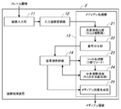
- FIG. 1 is an overall configuration diagram showing an imaging system according to a first embodiment.
- 1 is a block diagram showing a schematic configuration of an image processing apparatus 2 according to a first embodiment.
- Explanatory drawing explaining the outline of median processing by the conventional method Explanatory drawing explaining the outline
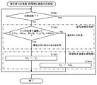
- FIG. 3 is a flowchart showing a processing procedure of the image processing apparatus 2 according to the first embodiment.
- the block diagram which shows schematic structure of the image processing apparatus 2 which concerns on 2nd Embodiment.
- FIG. 7 is a flowchart showing a processing procedure of the image processing apparatus 2 according to the second embodiment.
- FIG. 7 is a flowchart showing a processing procedure of the image processing apparatus 2 according to the third embodiment.
- summary of the median process by 4th Embodiment The flowchart which shows the process sequence of the image processing apparatus 2 which concerns on 4th Embodiment.
- FIG. 7 is a flowchart showing a processing procedure of the image processing apparatus 2 according to the fifth embodiment. Explanatory drawing explaining the outline
- the block diagram which shows schematic structure of the image processing apparatus 2 which concerns on 7th Embodiment.
- a first invention made to solve the above-described problem is an image processing apparatus that performs median processing in a time direction on a plurality of temporally continuous input images.
- a pixel value extraction unit that extracts pixel values, and a plurality of pixel values of a certain channel extracted for the target pixel by the pixel value extraction unit are rearranged, and a pixel value corresponding to a predetermined position after the rearrangement is selected.
- a pixel value selection unit a pixel value acquisition unit that acquires pixel values of other channels in the input image corresponding to the pixel value selected by the pixel value selection unit, the pixel value selection unit, and the pixel value acquisition
- An output pixel value determining unit that determines an output pixel value of the target pixel based on a pixel value obtained from the unit.
- the median processing can be speeded up.
- an appropriate median image can be acquired.
- 2nd invention is provided with the identifier provision part which provides the identifier corresponding to the said several input image to the pixel value extracted by the said pixel value extraction part,
- the said pixel value selection part is the said selected pixel
- An identifier assigned to a value is acquired, and the pixel value acquisition unit acquires pixel values of other channels based on the acquired identifier.
- the median process can be further speeded up.
- the third invention is configured to include an output image generation unit that generates an output image based on the output pixel value obtained for each pixel. According to this, an output image, that is, a median image can be acquired.
- the fourth invention is configured to include a display device for displaying the output image. According to this, an output image, that is, a median image can be visually confirmed.
- the fifth invention is configured such that the image value selection unit selects the value of the center position after the rearrangement as the predetermined position.
- the pixel value to be acquired is not limited to the median value, and may be any value near the center.
- the sixth invention is configured such that the input image is an image captured by an imaging device.
- the pixel value extraction unit acquires pixel values of R, G, and B channels from the input image, and the pixel value selection unit rearranges the G channel pixel values.
- the pixel values of the G channel that have characteristics closer to the brightness that are effective in determining whether or not the pixel value is a picture of snow particles are sorted, the pixel values of the snow grains are accurately excluded. Thus, it is possible to obtain a median image from which snowfall noise has been appropriately removed.
- the pixel value extraction unit acquires pixel values of the Y, U, and V channels from the input image, and the pixel value selection unit rearranges the Y channel pixel values.
- the pixel value in order to discriminate whether or not the pixel value is a picture of a snow particle, it is sorted by the luminance (Y channel pixel value) itself that is effective, so the pixel value of the snow grain is accurately excluded. In addition, it is possible to acquire a median image from which snowfall noise is appropriately removed.
- the ninth invention is configured such that the image value selection unit rearranges the plurality of pixel values in descending order.
- the input image is taken during snowfall, and snowfall noise appearing in the input image is removed by median processing in the time direction.
- snowfall correction processing can be performed at high speed.
- An eleventh aspect of the invention is an image processing method for performing median processing in a time direction on a plurality of temporally continuous input images, the step of extracting a pixel value of a target pixel from the plurality of input images; Rearranging a plurality of pixel values of a certain channel extracted for the target pixel by the step of extracting the pixel value, and selecting a pixel value corresponding to a predetermined position after the rearrangement; and Based on the pixel value obtained from the step of acquiring the pixel value of the other channel in the input image corresponding to the pixel value selected in the selecting step, the step of selecting the pixel value, and the step of acquiring the pixel value And determining an output pixel value of the target pixel.
- the twelfth aspect of the invention is a motion determination unit that determines whether or not the target pixel is a pixel having motion, and whether the pixel of interest shows a predetermined noise when the motion determination unit determines that the pixel has motion,
- a subject determination unit that determines whether the noise is something other than a predetermined noise; and if the subject determination unit determines that the noise is a predetermined noise, the pixel value determined by the output pixel value determination unit is used to determine the predetermined noise.
- a corrected image generation unit that uses the pixel value of the input image is provided.
- the pixel of interest displays noise such as snowfall noise (for example, due to a small object moving in the atmosphere)
- the pixel value determined by the output pixel value determination unit that is, the median image Therefore, noise such as snowfall noise can be removed.
- the pixel value of the input image that is, the pixel value of the captured image that has not undergone median processing, is used, so there is a pixel that moves other than noise. It is possible to reduce the afterimage generated when the image is generated.
- FIG. 1 is an overall configuration diagram illustrating an imaging system according to the first embodiment.
- This imaging system includes an imaging device 1 that images a subject, an image processing device 2 that performs image processing on a frame image (captured image) obtained by the imaging device 1, and a processed image obtained by the image processing device 2. And a display device 3 for displaying.
- the imaging device 1, the image processing device 2, and the display device 3 may be configured integrally or connected via a communication network.
- the imaging device 1 is used as a surveillance camera that images an outdoor subject.
- snowfall correction processing is performed to remove snowfall noise generated in the frame image captured during snowfall by the imaging device 1.
- it is effective for monitoring road conditions (such as traffic volume and road surface conditions), train conditions (track conditions, railroad crossings, station premises), river flooding conditions, etc. during snowfall.
- the image data obtained by the imaging device 1 is stored in an appropriate storage medium, and the image data is read from the storage medium.
- a configuration in which the image processing apparatus 2 performs image processing is also possible.
- the processed image obtained by the image processing apparatus 2 can be output as a moving image in addition to being output as a still image.
- the image data obtained by the image processing device 2 is stored in an appropriate storage medium, and the image data is read from the storage medium.
- a configuration in which display processing is performed by the display device 3 is also possible.
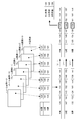
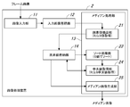
- FIG. 2 is a block diagram showing a schematic configuration of the image processing apparatus 2 according to the first embodiment.
- the image processing apparatus 2 includes an image input unit 11, an input image storage unit 12, a median processing unit 13, and a pixel value storage unit 14.
- the input image storage unit 12 stores a plurality of frame images input to the image input unit 11.
- the median processing unit 13 performs snowfall correction processing that removes snowfall noise in the frame image by median processing.
- the pixel value storage unit 14 stores the pixel value acquired by the median processing unit 13.
- the median processing unit 13 performs median processing in a time direction for a predetermined number of frame images, and includes a pixel value extracting unit 21, a number assigning unit (identifier assigning unit) 22, and a sort processing unit (pixel value).
- a selection unit) 23 a median value acquisition unit (pixel value acquisition unit) 24, and a median image generation unit (output pixel value determination unit) 25.
- the median processing unit 13 is realized by executing a predetermined program by the CPU.
- the pixel value extracting unit 21 performs a process of extracting the pixel value of each channel from a plurality of temporally continuous frame images with the target pixel as a target.
- a frame image in RGB format is input to the image processing apparatus 2, and the pixel value extraction unit 21 extracts R, G, and B values (pixel values of R, G, and B channels from the frame image). ) To get.
- the number assigning unit (identifier assigning unit) 22 assigns an index number (identifier) corresponding to the frame image as the extraction source to the pixel value of each channel acquired by the pixel value extracting unit 21, that is, the pixel value of each channel. Is associated with the index number.
- index values corresponding to the order of the frame images are assigned to the R, G, and B values.
- the sort processing unit 23 performs a sort process on a set of pixel values of one channel, that is, performs a process of rearranging the pixel values of one channel together with an index number in order of size, and obtains the median ( Get the index number assigned to (center position).
- the G values are rearranged in order of size, and the index number assigned to the median value is acquired.
- the pixel value to be acquired is not limited to the median value, and may be any value near the center.
- the median value acquisition unit 24 performs processing for selecting a pixel value assigned with the same index number as that assigned to the median value acquired by the sort processing unit 23 as the median value of each channel.
- R, G, and B median values are selected based on the index numbers acquired by the sort processing unit 23.
- a process for generating a median image based on the median of is performed.
- a median image is generated based on the median values of R, G, and B.
- the pixel value acquired by the pixel value extraction unit 21 and the index number assigned by the number assigning unit 22 are stored in the pixel value storage unit 14, and the sort processing unit 23, the median value acquisition unit 24, and the median image generation unit In each unit 25, the pixel value and the index number are extracted from the pixel value storage unit 14 and necessary processing is performed, and the pixel value acquired by the processing of each unit is stored in the pixel value storage unit 14.
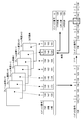
- FIG. 3 is an explanatory diagram for explaining the outline of the median processing according to the conventional method.
- FIG. 4 is an explanatory diagram for explaining the outline of the median processing according to the first embodiment.
- each value of R, G and B (pixel value of each channel of R, G and B) takes a value of 0 to 255.
- the median processing is performed on a total of seven frame images of the target frame image (t) and the three frame images before and after the frame image (t ⁇ 3 to t ⁇ 1, t + 1 to t + 3).
- the number of frame images to be subjected to median processing is not limited to seven.
- the R, G, and B values of the pixel of interest are acquired from each frame image, and the sorting process is performed for each of the R, G, and B values.
- the median values of R, G and B are obtained.
- the R, G, and B values of the target pixel acquired from each frame image are index numbers corresponding to the order of the frame images ( 1 to 7) are assigned, and then the sorting process is performed only on the G value.
- the index numbers are also rearranged in association with the G value.
- an index number (here, “6”) assigned to the G value (G median) of the middle rank is acquired, and then each of R, G, and B to which the same index number is assigned.
- the value is chosen as the median value of R, G and B.
- the channel to be sorted is not limited to the G channel, but may be the R or B channel. However, the G channel is most effective for RGB images.
- the sort process is performed only on the G value, so that the median process can be speeded up.
- the sorting process is performed with G values having characteristics closer to the luminance effective in determining whether or not the pixel value represents a snow particle, it is possible to accurately eliminate the pixel value representing the snow particle and reduce snowfall noise. It is possible to obtain a clear median image from which is appropriately removed.
- the obtained combination of R, G, and B median values actually exists in any of the original frame images, an appropriate median image can be acquired.
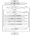
- FIG. 5 is a flowchart showing the processing procedure of the median processing unit 13.
- a plurality of temporally continuous frame images are input to the image input unit 11 and stored in the input image storage unit 12 (ST101).
- a process for each pixel (ST104 to ST107) is performed through a determination as to whether all frame images have been completed (ST102) and a determination as to whether all pixels have been completed (ST103).
- the pixel value extraction unit 21 performs a process of acquiring the R, G, and B values of the target pixel from the seven frame images (ST104), and then the numbering unit 22 Then, a process of assigning an index number to each value of R, G, and B is performed (ST105), and then the G value is rearranged in order of magnitude by the sort processing unit 23 and assigned to the median value.
- the process of acquiring the index number is performed (ST106), and then the median value acquisition unit 24 performs the process of selecting the R, G, and B median values based on the index numbers acquired by the sort processing unit 23. (ST107).
- the process for one pixel is completed, and this process is repeated until all the pixels in one frame image are completed.
- the median image generation unit At 25 a median image is generated based on the median values of R, G, and B for each pixel (ST108). The above processing is repeated until all frame images are completed.
- FIG. 6 is a block diagram illustrating a schematic configuration of the image processing apparatus 2 according to the second embodiment.
- FIG. 7 is an explanatory diagram for explaining the outline of the median processing according to the second embodiment.
- FIG. 8 is a flowchart showing a processing procedure of the image processing apparatus 2 according to the second embodiment. Note that points not particularly mentioned here are the same as in the above embodiment.
- the median processing unit 13 includes a pixel value extraction unit 21, a numbering unit 22, a sort processing unit 23, a central processing unit, as in the first embodiment.
- the value acquisition unit 24 and the median image generation unit 25 are provided.
- a pixel value conversion unit 26 is further provided.
- the pixel value conversion unit 26 includes a pixel value extraction unit. A process of calculating another pixel value from the pixel value of each channel acquired in 21 is performed.
- a frame image in the RGB format is input to the image processing apparatus 2 and, as shown in FIG. 7, the Y value is calculated from the R, G, and B values.
- a process for calculating (luminance) (ST206 in FIG. 8) is performed by the pixel value conversion unit.
- a process (ST207 in FIG. 8) of rearranging the Y values acquired by the pixel value conversion unit 26 in order of size and acquiring the index number assigned to the median value is performed by the sort processing unit 23,
- the median value acquisition unit 24 performs processing for selecting R, G, and B median values based on the index numbers acquired by the sort processing unit 23 (ST208 in FIG. 8).
- the sort process need only be performed on the Y value (luminance), so that the median process can be speeded up. Further, since a pixel value conversion process for calculating the Y value is required, the amount of calculation is increased as compared with the first embodiment, but the luminance itself is effective in determining whether or not the pixel value represents a snow particle. Since the sorting process is performed in step S1, it is possible to obtain a clear median image from which snowfall noise is appropriately removed by accurately excluding the pixel values obtained by capturing snow particles.
- FIG. 9 is a block diagram illustrating a schematic configuration of the image processing apparatus 2 according to the third embodiment.
- FIG. 10 is an explanatory diagram for explaining the outline of the median processing according to the third embodiment.
- FIG. 11 is a flowchart showing a processing procedure of the image processing apparatus 2 according to the third embodiment. The points not particularly mentioned are the same as in the above embodiment.
- the median processing unit 13 includes a pixel value extraction unit 21, a numbering unit 22, a sort processing unit 23, A value acquisition unit 24 and a median image generation unit 25 are provided.
- a frame image in YUV format is input to the image processing apparatus 2, and the pixel value extraction unit 21 receives a frame image.
- U and V values pixel values of Y, U and V channels).
- the sort processing unit 23 performs processing (ST306 in FIG. 11) for rearranging the Y values in order of size and obtaining the index number assigned to the median, and then sorting Based on the index number acquired by the processing unit 23, processing for selecting the median values of Y, U, and V (ST307 in FIG. 11) is performed by the median value acquisition unit 24.
- the median process can be speeded up.
- the sorting process is performed with the brightness itself that is effective in determining whether or not the pixel value represents a snow particle, the pixel value representing the snow particle is accurately excluded, and snowfall noise is appropriately removed. A clear median image can be acquired.
- FIG. 12 is a block diagram illustrating a schematic configuration of the image processing apparatus 2 according to the fourth embodiment.
- FIG. 13 is an explanatory diagram for explaining the outline of the median processing according to the fourth embodiment.
- FIG. 14 is a flowchart showing a processing procedure of the image processing apparatus 2 according to the fourth embodiment. The points not particularly mentioned are the same as in the above embodiment.
- the median processing unit 13 includes a pixel value extracting unit 21, a number assigning unit 22, a pixel value converting unit 26, as in the second embodiment.
- a sort processing unit 23, a median value acquisition unit 24, and a median image generation unit 25 are provided.
- a RAW format frame image based on a Bayer array is input to the image processing device 2.
- the pixel value extraction unit 21 performs a process of acquiring R, G1, G2, and B values (pixel values of R, G1, G2, and B channels) from the frame image.
- a process of calculating a G value that is an average value of the G1 value and the G2 value (ST406 in FIG. 14) is performed by the pixel value conversion unit 26, and then acquired by the pixel value conversion unit 26.
- the sort processing unit 23 performs processing (ST407 in FIG. 14) for rearranging the G values in order of magnitude and obtaining the index number assigned to the median value, and then the index number obtained by the sort processing unit 23
- the median value acquisition unit 24 performs processing for selecting median values of R, G1, G2 and B based on the above (ST408 in FIG. 14).
- the calculation burden of the sort process can be reduced, and a pixel value conversion process for calculating the G value is necessary.
- the amount of calculation of the entire median processing is reduced, so that the median processing can be speeded up.
- the sorting process is performed with G values having characteristics closer to the luminance effective in determining whether or not the pixel value is a photograph of snow particles, the pixel values that represent snow particles are accurately excluded, and snowfall noise It is possible to obtain a clear median image from which is appropriately removed.
- FIG. 15 is a block diagram illustrating a schematic configuration of the image processing apparatus 2 according to the fifth embodiment.
- FIG. 16 is an explanatory diagram for explaining the outline of the median processing according to the fifth embodiment.
- FIG. 17 is a flowchart showing a processing procedure of the image processing apparatus 2 according to the fifth embodiment. Note that points not particularly mentioned here are the same as in the above embodiment.
- the median processing unit 13 has a pixel value extraction unit 21, a sort processing unit 23, a median value acquisition unit 24, The median image generation unit 25 is provided.
- the number assigning unit 22 in the first embodiment is not provided, and as shown in FIG. An index number (identifier) corresponding to the frame image that is the extraction source is not assigned to the acquired R, G, and B values.
- a sort process is performed on the set of G values acquired by the pixel value extraction unit 21 to obtain the median value (ST505 in FIG. 17), and then the sort process unit 23 performs the pixel value. From the pixel value combinations for each frame image acquired by the extraction unit 21, a combination of pixel values including a G value that matches the G median value acquired by the sort processing unit 23 is searched, and the combination of the found pixel values is determined.
- the median value acquisition unit 24 performs processing for setting the median values of R, G, and B (ST506 in FIG. 17).
- the sort processing unit 23 there may be a plurality of combinations of pixel values having a G value that matches the G median value acquired by the sort processing unit 23.
- a combination of pixel values including a G value that matches the G median value When the search process for searching for is performed in order from the beginning, the first combination of pixel values found may be selected as the median value. Further, one of the combinations of corresponding pixel values may be selected at random.
- the R, G, and B values acquired by the pixel value extraction unit 21 are stored in the pixel value storage unit 14, and the G values acquired by the sort processing unit 23 are targeted for this.
- the search process for searching for a combination of pixel values including the G value that matches the median value is performed, the search process may be performed on the frame image itself. In this case, by extracting the G value from each frame image and collating whether or not the G value matches the G median value acquired by the sort processing unit 23, the G center acquired by the sort processing unit 23 is obtained. A frame image having a G value that matches the value is specified, and each value of R and B is extracted from this frame image, and this is set as the median value of R and B.
- the median values of R, G, and B can be obtained based on
- FIG. 18 is an explanatory diagram for explaining the outline of the median processing according to the sixth embodiment. Note that points not particularly mentioned here are the same as in the above embodiment.
- the schematic configuration of the image processing apparatus 2 in the sixth embodiment is the same as that of the fifth embodiment in FIG. 15, but in particular, here, only the G value that is the target of the sorting process is selected by the pixel value extraction unit 21. I try to extract.
- the median value acquisition unit 24 searches for a frame image having a G value that matches the G median value acquired by the sort processing unit 23, extracts R and B values from the found frame image, and extracts these values as R and B.
- the sixth embodiment there may be a plurality of frame images having a G value that matches the G median acquired by the sort processing unit 23.
- G value that matches the G median acquired by the sort processing unit 23.
- What is necessary is just to select as a median the pixel value of the frame image found first when the search process which searches for the frame image which has matching G value is performed in order from the beginning. Further, one of the corresponding frame images may be selected at random.
- the pixel value extraction unit 21 only needs to extract the G value that is the target of the sorting process, and it is not necessary to extract the pixel values of all the channels from all the target frame images. Therefore, the processing amount of the pixel value extraction process can be reduced.
- the process of assigning the index number (identifier) to the pixel value is not performed, and the G value is associated with the frame image from which the extraction is performed. Therefore, in order to specify a frame image having a G value that matches the G median value acquired by the sorting process, a process for extracting the G value from the frame image again is necessary. If an index number (identifier) corresponding to the frame image that is the extraction source is assigned to the G value acquired by the pixel value extraction unit 21, it matches the G median value acquired by the sorting process based on the index number. Since the frame image having the G value can be easily specified, the process of acquiring the median values of R and B is facilitated.
- an index number represented by a number (1 to 7) is used as an identifier given to a pixel value.
- the present invention is not limited to this, It is also possible to use characters.
- the pixel value conversion unit 26 calculates the Y value (luminance) and the G value (the average value of the G1 value and the G2 value).
- the present invention is not limited to this, and the pixel value may be converted into an appropriate kind of pixel value so that an appropriate median value can be obtained according to the use of the median processing.
- the configuration corresponding to the first embodiment that is, the configuration in which the median values of R, G, and B are obtained by performing the sort process on the G value.
- the pixel value acquired by the pixel value extraction unit 21 is not assigned an index number (identifier) corresponding to the frame image from which the pixel value is extracted, or in the sorting process.
- the configuration for extracting only the pixel values of necessary channels can be applied to the configuration for performing the sorting process with the pixel values that can be directly acquired from the frame image, as shown in the third embodiment.
- pixel value conversion processing for calculating different pixel values from pixel values of a plurality of channels.
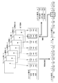
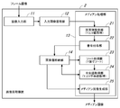
- FIG. 19 is a block diagram illustrating a schematic configuration of the image processing apparatus 2 according to the seventh embodiment.
- FIG. 20 is an explanatory diagram for explaining an overview of the processing of each image performed by the image processing apparatus 2. Note that t, t ⁇ 1, and t + 1 attached to each image in FIG. 20 indicate the imaging time. The imaging time t is attached to the image at the time of interest, and the imaging time t is added to the images before and after that. -1, t + 1 are shown.
- the image processing apparatus 2 includes an image input unit 11, an input image storage unit 12, a median processing unit 13, a median image storage unit 31, a background image generation unit 32, and a background image storage unit. 33, a subject determination unit 34, and a snowfall correction image generation unit 35.
- the input image storage unit 12 stores a plurality of frame images (input images) input to the image input unit 11.
- the median processing unit 13 performs median processing in a time direction on a predetermined number (for example, seven) of input images stored in the input image storage unit 12 to generate a median image. Processing is performed.
- the median process is performed on a total of seven input images including the input image at the time of interest and the three input images before and after the input image.
- the number of input images to be subjected to median processing is not limited to seven.
- the median processing may be performed using only the input image at the point of interest and the previous input image or only the subsequent input image.
- the median image generated by the median processing unit 13 is stored.
- the median image of the previous time generated by the previous process and the attention generated by the current process are noted.
- the median image at the time is accumulated.
- the background image generation unit 32 includes a primary image generation unit 41 and a secondary image generation unit 42.
- the primary image generation unit 41 the input image at the point of interest stored in the input image storage unit 12, the median image at the point of interest stored in the median image storage unit 31, and the median image at the previous point in time are stored. Based on the difference between the frames, a process for generating a primary image reflecting a change appearing on the subject is performed.
- the secondary image generation unit 42 performs a process of generating a background image (secondary image) based on the primary image at the point of interest acquired by the primary image generation unit 41 and the background image at the previous point in time. Is called.
- the background image storage unit 33 stores the background image of the previous time point generated by the previous process and the background image of the point of interest generated by the current process.
- the background image storage unit 33 stores the background image.
- the secondary image generation unit 42 Based on the background image at the previous time point, the secondary image generation unit 42 performs processing to generate a background image at the point of interest, and the background image at the point of interest generated by the background image generation unit 32 is generated. It is stored in the background image storage unit 33.
- the subject determination unit 34 is based on the input image at the point of interest stored in the input image storage unit 12, the input image at the next point in time, and the background image at the point of interest stored in the background image storage unit 33. Then, subject determination processing is performed to determine whether each pixel is a photograph of a subject that moves other than snow particles.
- the moving subject refers to a subject that moves relative to the imaging device 1, that is, a subject whose position changes in a plurality of temporally continuous input images, and the subject itself moves.
- the stationary subject moves as a whole with respect to the imaging device 1 as the imaging device 1 moves, as in the case where the imaging device 1 performs panning and tilting operations.
- the snowfall correction image generation unit 35 generates a snowfall correction image based on the input image stored in the input image storage unit 12, the median image stored in the median image storage unit 31, and the determination result of the subject determination unit 34. Processing is performed.
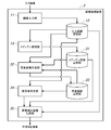
- FIG. 21 is a flowchart showing a procedure of processing performed in the image processing apparatus 2.
- a process of initializing the median image of the median image storage unit 31 (ST601) and a process of initializing the background image of the background image storage unit 33 (ST602) are performed.
- the images required for the following processing that is, the median image and the background image at the previous time do not exist in the median image storage unit 31 and the background image storage unit 33.
- the current input image is stored as a median image and a background image at the previous time.
- median processing is performed by the median processing unit 13 (ST604)
- background update processing is performed by the background image generation unit 32 (ST605)
- subject determination unit 34 and snowfall are performed.
- the correction image generation unit 35 performs subject determination processing and snowfall correction image generation processing (ST606).
- processing for updating the median image in the median image storage unit 31 (ST607) and processing for updating the background image in the background image storage unit 33 (ST608) are performed.
- a process of replacing the median image and background image at the point of interest stored in the median image storage unit 31 and the background image storage unit 33 with the median image and background image at the previous point in time is performed.
- the snowfall correction image at the point of interest generated by the snowfall correction image generation unit 35 is output (ST609).
- FIG. 22 is a flowchart showing the procedure of the background update process performed by the background image generation unit 32.
- the primary image generation unit 41 performs a process of generating a primary image reflecting a change appearing in the subject from the difference between frames.
- this primary image generation process first, it is determined whether or not all the pixels are finished (ST701), and the process of acquiring the pixel value of the primary image until all the pixels are finished (ST702 to ST704). ) Is repeated for each pixel.
- processing for determining the pixel value Vb1 t of the primary image at the point of interest is performed (ST703, ST704) according to the result of the determination of whether or not a noticeable change has occurred in the subject (ST702).
- the pixel value of the input image the vi t is determined to be the pixel values Vb1 t of the primary image (ST 703).
- the luminance change amount (Ym t ⁇ 1 ⁇ Yi t ) is equal to or smaller than the threshold Th (No in ST702), it is determined that the luminance change is caused by noise, and the pixel value Vm t of the median image is set to 1. The pixel value Vb1 t of the next image is determined (ST704).
- the threshold value Th may be set based on a change in luminance when it should be removed as noise, and may be set to 15 at 256 gradations, for example.
- luminance variation (Ym t-1 -Yi t) is a negative value
- the threshold Th is positive Since the value is (0 to 255), the luminance change amount (Ym t ⁇ 1 ⁇ Yi t ) is smaller than the threshold value Th, that is, since Equation 1 is not satisfied, the median pixel value is adopted, thereby causing snowfall noise. Can be removed.
- the median image at the previous time point is used, but the input image at the previous time point can also be used. It is. However, since the snow noise is removed from the median image, if the median image is used, the luminance change amount appears greatly, so that the determination accuracy can be improved.
- the pixel value Vb1 t of the primary image at the point of interest acquired by the primary image generation unit 41 and the pixel value Vb of the background image at the previous point in time are obtained. From t ⁇ 1 , the pixel value Vb t of the background image at the point of interest is obtained.
- Vb t (1 ⁇ c) ⁇ Vb t ⁇ 1 + c ⁇ Vb1 t (Formula 2)
- the background update rate c is a ratio indicating how much the primary image acquired by the primary image generation unit 41 is reflected in the background image.
- This background update rate c is given by the reciprocal (1 / N) of the update frame number N.
- the update frame number N indicates how many frame images (input images) the background image is updated, and is set by the user. According to Equation 2, the change in the subject appearing in the primary image does not immediately appear in the background image, and the state of the changed subject continues to appear as it is, and gradually appears in the background image. By increasing / decreasing, it is possible to adjust the time until a change that occurs in the background subject clearly appears in the background image.
- the number of update frames N is small, the influence of the primary image becomes large and the background image may not be stable. Conversely, if the number of update frames N is large, it is difficult for changes in the subject to be reflected in the background image. Therefore, by appropriately setting the number of updated frames N according to the imaging situation or the like, it is possible to generate a stable background image that appropriately reflects changes in the subject. For example, when the subject changes greatly as in the case where the imaging apparatus 1 performs panning or tilting operation, the change in the subject can be quickly reflected in the background image by reducing the number of update frames N. .
- the background update rate c can be changed during the operation by performing the process of setting the background update rate c in the middle of the flow (ST706). In other words, during the operation, an input operation of the update frame number N by the user is accepted, and the next processing is performed at the background update rate c calculated from the update frame number N input here.
- FIG. 23 is a flowchart showing a procedure of subject determination processing and snowfall correction image generation processing performed by the subject determination unit 34 and the snowfall correction image generation unit 35.
- FIG. 24 is an explanatory diagram for explaining an overview of processing performed by the subject determination unit 34.
- a process for determining whether or not each pixel is a photograph of a subject other than a snow particle is performed.
- this subject determination processing when a state in which the pixel value of the input image deviates from the threshold value continuously occurs in a predetermined number of input images that are continuous in time, the pixel has a motion other than a snow particle.
- the pixel is It is determined that the subject is not a photograph of a moving subject other than a grain, that is, a photograph of a snow grain or a background (substantially stationary subject).
- two input images that are temporally continuous that is, an input image at a point of interest and an input image at a point after that are set as determination targets.
- the threshold value to be compared with the pixel value of the input image is set with reference to the pixel value of the background image, and the luminance is adopted as the pixel value.
- an upper threshold (Yb t + WthH) and a lower threshold (Yb t ⁇ WthL) are set based on the threshold widths WthL and WthH based on the luminance Yb t of the background image. It is compared with the luminance Yi t of the input image.
- the judgment formula at this time is the following formulas 3 and 4. Yi t ⁇ Yb t ⁇ WthL (Formula 3) Yi t ⁇ Yb t + WthH (Formula 4)
- Equation 3 the luminance Yi t of the input image is a determination formula is smaller than the luminance Yb t of the background image
- Equation 4 the luminance Yi t of the input image is a luminance Yb t is greater than the determination formula of the background image
- negative threshold width WthL the positive threshold width WthH are set separately based on the pixel value Yb t of the background image.
- the threshold widths WthL and WthH are fluctuation ranges for determining whether or not the subject is a moving subject, but WthL is based on the luminance of the subject other than the snow particles.
- WthL is based on the luminance of the subject other than the snow particles.
- WthH is based on the luminance of the subject other than the snow particles.
- WthL it is possible to reduce an afterimage of a subject (for example, a black car body) having a lower brightness than the background.
- WthH it is possible to reduce afterimages of a subject (for example, the body of a white car or the headlight part of a lit car) having a higher brightness than the background by removing snow particles.
- the threshold widths WthL and WthH may be set by the user while confirming on the screen the effects of removing snow particles and reducing the afterimage.
- any of the input image point after the one and the input image at the time of interest, smaller than the luminance Yi t is lower threshold (Yb t -WthL) That is, Formula 3 is not established continuously with two input images.
- the target pixel is a copy of a snow particle
- the snow particle moves away from the target pixel while changing to the input image at the next time point. It will not be a reflection of snow particles. Therefore, as shown in FIG. 24 (C), the luminance Yi t in the input image at the time of interest is larger than the upper threshold (Yb t + WthH), the luminance in the input image point after one yi t is returned to the vicinity of the luminance Yb t background, lower than the upper threshold, i.e. formula 4 is not satisfied successively with two input images.
- the input image at the point of interest and the input image at the next point in time are either, the luminance Yi t of the input image is larger than the upper threshold (Yb t + WthH), i.e. formula 4 in succession with two input images is established.
- the pixel of interest is a photograph of a moving subject other than a snow particle, based on whether or not Expression 3 or Expression 4 is successively established with two input images. That is, when Expression 3 or Expression 4 is established continuously for two input images, it is determined that the pixel of interest is a moving subject other than snow particles, and the expression is continuously applied for two input images. When neither of 3 nor Expression 4 holds, it is determined that the target pixel is a photograph of a snow particle or a background (substantially stationary subject).
- the process of determining a pixel value Vc t of snowfall correction image according to the result of the subject determined by the object determination unit 34 is performed (ST 803 , ST804).
- Equation 3 or Equation 4 is established, that is, when the target pixel is a photograph of a moving subject other than a snow particle (Yes in ST802), the pixel values Vi t determine the pixel value Vc t snowfall corrected image (ST 803).
- the target pixel is a photograph of a subject that moves other than the snow particles
- the pixel value of the input image that has not been subjected to median processing is adopted, and thus the subject of the subject that moves other than the snow particles is adopted. It is possible to avoid the image remaining as it is and the afterimage from appearing.
- the pixel of interest is a copy of snow particles
- the pixel value of the median image is adopted, thereby removing snowfall noise.
- the target pixel is a copy of the background, the pixel value of the median image is adopted.
- the luminance may exceed the upper threshold value continuously in two input images.
- the pixel is a photograph of a moving subject other than the snow particle. Since the pixel value of the input image is adopted, snowfall noise is not removed, but the frequency of such a case is low, and a practically sufficient effect can be obtained.
- FIG. 25 is a block diagram illustrating a schematic configuration of the image processing apparatus 2 according to the eighth embodiment. Note that points not particularly mentioned here are the same as in the above embodiment.
- the image processing apparatus 2 includes an image input unit 11, an input image storage unit 12, a median processing unit 13, a median image storage unit 31, and a background image generation. Unit 32, background image storage unit 33, subject determination unit 34, and snowfall correction image generation unit 35.
- the image processing apparatus 2 includes a stabilization processing unit 51. And a stabilized image storage unit 52.
- the stabilization processing unit 51 performs a stabilization process that suppresses the state in which the image of the subject in the input image is shaken as a whole when the imaging apparatus 1 is shaken due to camera shake or the like. By this stabilization processing, it is possible to avoid a deterioration in image quality such as an afterimage due to the movement of the subject image.
- the stabilized image storage unit 52 the stabilized image generated by the stabilization processing unit 51 is stored.
- the stabilized image accumulated in the stabilized image accumulation unit 52 is used for each processing of the median processing unit 13, the background image generation unit 32, the subject determination unit 34, and the snowfall correction image generation unit 35.
- the input image is used for each process of the median processing unit 13, the background image generation unit 32, the subject determination unit 34, and the snowfall correction image generation unit 35.
- the input image instead, a stabilized image is used.
- the seventh embodiment in subject determination, at a general frame rate (for example, 30 fps), snow particles move and change from the target pixel while changing to the input image at the next time point. Focusing on the fact that two input images that are temporally continuous are targeted for determination, it is possible to determine three or more input images as the determination target. For example, when the frame rate increases, the determination target It may be better to increase the number of input images.
- a general frame rate for example, 30 fps
- the snowfall correction process for removing snowfall noise has been described.
- the present invention is not limited to such a snowfall correction process, and is used for removing general noise other than snowfall noise.
- it is suitable for the purpose of removing noise caused by noise objects (small objects that fall or float in the atmosphere) that cause noise other than snow particles.
- noise objects small objects that fall or float in the atmosphere
- the image processing apparatus and the image processing method according to the present invention have an effect that the processing speed can be increased when performing median processing in the time direction on a color image, and a plurality of captured images that are temporally continuous. It is useful as an image processing apparatus and an image processing method for performing median processing in the time direction for the above.
Abstract
Description
図1は、第1実施形態に係る撮像システムを示す全体構成図である。この撮像システムは、被写体を撮像する撮像装置1と、撮像装置1で得られたフレーム画像(撮像画像)に対して画像処理を行う画像処理装置2と、画像処理装置2で得られた処理画像を表示する表示装置3と、を備えている。なお、撮像装置1、画像処理装置2及び表示装置3は一体的に構成されても良いし、通信ネットワークを介して接続されて構成されても良い。
図6は、第2実施形態に係る画像処理装置2の概略構成を示すブロック図である。図7は、第2実施形態によるメディアン処理の概要を説明する説明図である。図8は、第2実施形態に係る画像処理装置2の処理手順を示すフロー図である。なお、ここで特に言及しない点は前記の実施形態と同様である。
Y=0.299R+0.587G+0.114B
図9は、第3実施形態に係る画像処理装置2の概略構成を示すブロック図である。図10は、第3実施形態によるメディアン処理の概要を説明する説明図である。図11は、第3実施形態に係る画像処理装置2の処理手順を示すフロー図である。なお、特に言及しない点は前記の実施形態と同様である。
図12は、第4実施形態に係る画像処理装置2の概略構成を示すブロック図である。図13は、第4実施形態によるメディアン処理の概要を説明する説明図である。図14は、第4実施形態に係る画像処理装置2の処理手順を示すフロー図である。なお、特に言及しない点は前記の実施形態と同様である。
図15は、第5実施形態に係る画像処理装置2の概略構成を示すブロック図である。図16は、第5実施形態によるメディアン処理の概要を説明する説明図である。図17は、第5実施形態に係る画像処理装置2の処理手順を示すフロー図である。なお、ここで特に言及しない点は前記の実施形態と同様である。
図18は、第6実施形態によるメディアン処理の概要を説明する説明図である。なお、ここで特に言及しない点は前記の実施形態と同様である。
図19は、第7実施形態に係る画像処理装置2の概略構成を示すブロック図である。図20は、画像処理装置2で行われる各画像の処理の概要を説明する説明図である。なお、図20で各画像に付されたt,t-1,t+1は撮像時刻を示すものであり、注目する時点の画像に撮像時刻tを付し、その前後の時点の画像に撮像時刻t-1,t+1を付して示している。
Ymt-1-Yit>Th (式1)
Vbt=(1-c)×Vbt-1+c×Vb1t (式2)
ここで、背景更新率cは、1次画像生成部41で取得した1次画像をどの程度背景画像に反映させるかを示す割合である。
Yit≦Ybt-WthL (式3)
Yit≧Ybt+WthH (式4)
図25は、第8実施形態に係る画像処理装置2の概略構成を示すブロック図である。なお、ここで特に言及しない点は前記の実施形態と同様である。
2 画像処理装置
11 画像入力部
12 入力画像蓄積部
13 メディアン処理部
14 画素値格納部
21 画素値抽出部
22 番号付与部(識別子付与部)
23 ソート処理部(画素値選択部)
24 中央値取得部(画素値取得部)
25 メディアン画像生成部(出力画素値決定部)
26 画素値変換部
32 背景画像生成部
34 被写体判定部
35 降雪補正画像生成部(補正画像生成部)
Claims (12)
- 時間的に連続する複数の入力画像に対して時間方向のメディアン処理を行う画像処理装置であって、
前記複数の入力画像から注目画素の画素値を抽出する画素値抽出部と、
前記画素値抽出部により前記注目画素について抽出された、あるチャンネルの複数の画素値を並び替え、並び替え後の所定の位置に対応する画素値を選択する画素値選択部と、
前記画素値選択部で選択された画素値に対応する前記入力画像における他のチャンネルの画素値を取得する画素値取得部と、
前記画素値選択部及び前記画素値取得部より得られる画素値に基づいて前記注目画素の出力画素値を決定する出力画素値決定部と、を備えた画像処理装置。 - 前記画素値抽出部により抽出される画素値に、前記複数の入力画像に対応した識別子を付与する識別子付与部を備え、
前記画素値選択部は、前記選択した画素値に付与された識別子を取得し、
前記画素値取得部は、前記取得した識別子に基づいて他のチャンネルの画素値を取得する請求項1に記載の画像処理装置。 - 画素毎に得られた前記出力画素値に基づいて出力画像を生成する出力画像生成部を備えた請求項1に記載の画像処理装置。
- 前記出力画像を表示する表示装置を備えた請求項3に記載の画像処理装置。
- 前記画像値選択部は、前記所定の位置として並び替え後の中央位置の値を選択する請求項1に記載の画像処理装置。
- 前記入力画像は撮像装置により撮像された画像である請求項1に記載の画像処理装置。
- 前記画素値抽出部は、前記入力画像からR、GおよびBの各チャンネルの画素値を取得し、
前記画素値選択部は、Gチャンネルの画素値を並び替える請求項1に記載の画像処理装置。 - 前記画素値抽出部は、前記入力画像からY、UおよびVの各チャンネルの画素値を取得し、
前記画素値選択部は、Yチャンネルの画素値を並び替える請求項1に記載の画像処理装置。 - 前記画像値選択部は、前記複数の画素値を大きい順に並び替える請求項1に記載の画像処理装置。
- 前記入力画像は降雪時に撮像されたものであり、時間方向のメディアン処理によって前記入力画像に現れる降雪ノイズを除去する請求項1に記載の画像処理装置。
- 時間的に連続する複数の入力画像に対して時間方向のメディアン処理を行う画像処理方法であって、
前記複数の入力画像から注目画素の画素値を抽出するステップと、
前記画素値を抽出するステップにより前記注目画素について抽出された、あるチャンネルの複数の画素値を並び替え、並び替え後の所定の位置に対応する画素値を選択するステップと、
前記画素値を選択するステップで選択された画素値に対応する前記入力画像における他のチャンネルの画素値を取得するステップと、
前記画素値を選択するステップ及び前記画素値を取得するステップより得られる画素値に基づいて前記注目画素の出力画素値を決定するステップと、を有する画像処理方法。 - 前記注目画素が動きのある画素か否かを判定する動き判定部と、
前記動き判定部により動きがある画素と判定された場合、所定のノイズを示すものか、所定のノイズ以外を示すものかを判定する被写体判定部と、
前記被写体判定部により所定のノイズと判定された場合は、前記出力画素値決定部により決定された画素値を使用し、所定のノイズ以外と判定された場合は、前記入力画像の画素値を使用する補正画像生成部と、を備えた請求項1に記載の画像処理装置。
Priority Applications (3)
| Application Number | Priority Date | Filing Date | Title |
|---|---|---|---|
| JP2014538194A JP6206732B2 (ja) | 2012-09-27 | 2013-09-26 | 画像処理装置および画像処理方法 |
| EP13840385.2A EP2903263A4 (en) | 2012-09-27 | 2013-09-26 | IMAGE PROCESSING DEVICE AND METHOD |
| US14/423,818 US9672605B2 (en) | 2012-09-27 | 2013-09-26 | Image processing device and image processing method |
Applications Claiming Priority (4)
| Application Number | Priority Date | Filing Date | Title |
|---|---|---|---|
| JP2012-213909 | 2012-09-27 | ||
| JP2012213909 | 2012-09-27 | ||
| JP2012239849 | 2012-10-31 | ||
| JP2012-239849 | 2012-10-31 |
Publications (1)
| Publication Number | Publication Date |
|---|---|
| WO2014050117A1 true WO2014050117A1 (ja) | 2014-04-03 |
Family
ID=50387550
Family Applications (1)
| Application Number | Title | Priority Date | Filing Date |
|---|---|---|---|
| PCT/JP2013/005723 WO2014050117A1 (ja) | 2012-09-27 | 2013-09-26 | 画像処理装置および画像処理方法 |
Country Status (4)
| Country | Link |
|---|---|
| US (1) | US9672605B2 (ja) |
| EP (1) | EP2903263A4 (ja) |
| JP (1) | JP6206732B2 (ja) |
| WO (1) | WO2014050117A1 (ja) |
Families Citing this family (4)
| Publication number | Priority date | Publication date | Assignee | Title |
|---|---|---|---|---|
| US20160257252A1 (en) * | 2015-03-05 | 2016-09-08 | Lenovo (Singapore) Pte. Ltd. | Projection of images on side window of vehicle |
| JP6645294B2 (ja) * | 2016-03-22 | 2020-02-14 | 富士ゼロックス株式会社 | 画像読取装置 |
| US11170486B2 (en) * | 2017-03-29 | 2021-11-09 | Nec Corporation | Image analysis device, image analysis method and image analysis program |
| US10977924B2 (en) * | 2018-12-06 | 2021-04-13 | Electronics And Telecommunications Research Institute | Intelligent river inundation alarming system and method of controlling the same |
Citations (4)
| Publication number | Priority date | Publication date | Assignee | Title |
|---|---|---|---|---|
| JPH0973541A (ja) * | 1995-09-07 | 1997-03-18 | Hitachi Denshi Ltd | 物体検出装置及び物体検出方法 |
| JP2000115763A (ja) | 1998-10-09 | 2000-04-21 | Tateyama System Kenkyusho:Kk | 画像処理方法及び画像処理装置 |
| JP2008131609A (ja) * | 2006-11-26 | 2008-06-05 | Plusmic:Kk | 電荷増倍素子を用いた高感度・高速度の競技用電子判定装置 |
| WO2008111549A1 (ja) * | 2007-03-15 | 2008-09-18 | Kansai University | 移動物体ノイズ除去処理装置及び移動物体ノイズ除去処理プログラム |
Family Cites Families (7)
| Publication number | Priority date | Publication date | Assignee | Title |
|---|---|---|---|---|
| US5384865A (en) | 1992-06-01 | 1995-01-24 | Eastman Kodak Company | Adaptive, hybrid median filter for temporal noise suppression |
| US6088468A (en) | 1995-05-17 | 2000-07-11 | Hitachi Denshi Kabushiki Kaisha | Method and apparatus for sensing object located within visual field of imaging device |
| JP4528529B2 (ja) * | 2004-01-20 | 2010-08-18 | 株式会社東芝 | 超音波診断装置及び超音波画像データ処理方法 |
| US8160149B2 (en) * | 2007-04-03 | 2012-04-17 | Gary Demos | Flowfield motion compensation for video compression |
| US8340406B1 (en) * | 2008-08-25 | 2012-12-25 | Adobe Systems Incorporated | Location-weighted color masking |
| US9147260B2 (en) * | 2010-12-20 | 2015-09-29 | International Business Machines Corporation | Detection and tracking of moving objects |
| JP5924091B2 (ja) * | 2012-04-13 | 2016-05-25 | 株式会社リコー | 画像処理装置、画像処理システム、プログラム |
-
2013
- 2013-09-26 JP JP2014538194A patent/JP6206732B2/ja active Active
- 2013-09-26 WO PCT/JP2013/005723 patent/WO2014050117A1/ja active Application Filing
- 2013-09-26 US US14/423,818 patent/US9672605B2/en active Active
- 2013-09-26 EP EP13840385.2A patent/EP2903263A4/en not_active Withdrawn
Patent Citations (4)
| Publication number | Priority date | Publication date | Assignee | Title |
|---|---|---|---|---|
| JPH0973541A (ja) * | 1995-09-07 | 1997-03-18 | Hitachi Denshi Ltd | 物体検出装置及び物体検出方法 |
| JP2000115763A (ja) | 1998-10-09 | 2000-04-21 | Tateyama System Kenkyusho:Kk | 画像処理方法及び画像処理装置 |
| JP2008131609A (ja) * | 2006-11-26 | 2008-06-05 | Plusmic:Kk | 電荷増倍素子を用いた高感度・高速度の競技用電子判定装置 |
| WO2008111549A1 (ja) * | 2007-03-15 | 2008-09-18 | Kansai University | 移動物体ノイズ除去処理装置及び移動物体ノイズ除去処理プログラム |
Non-Patent Citations (2)
| Title |
|---|
| MIYAKE ET AL.: "Snowfall Noise Elimination Using a Time Median Filter", THE JOURNAL OF THE INSTITUTE OF IMAGE ELECTRONICS ENGINEERS OF JAPAN, vol. 30, no. 3, 2001, pages 251 - 259 |
| See also references of EP2903263A4 |
Also Published As
| Publication number | Publication date |
|---|---|
| US20150221073A1 (en) | 2015-08-06 |
| JPWO2014050117A1 (ja) | 2016-08-22 |
| EP2903263A1 (en) | 2015-08-05 |
| JP6206732B2 (ja) | 2017-10-04 |
| EP2903263A4 (en) | 2015-11-04 |
| US9672605B2 (en) | 2017-06-06 |
Similar Documents
| Publication | Publication Date | Title |
|---|---|---|
| JP3898606B2 (ja) | 動きベクトル検出方法及び装置並びにフレーム補間画像作成方法及び装置 | |
| EP2535864B1 (en) | Image processing device and method | |
| US8179466B2 (en) | Capture of video with motion-speed determination and variable capture rate | |
| TWI399703B (zh) | 往返縮放之影像放大方法 | |
| JP6104680B2 (ja) | 画像処理装置、撮像装置、監視システム、符号化装置、画像処理方法 | |
| KR102314703B1 (ko) | 이미지 처리를 위한 조인트 딕셔너리 생성 방법, 그 조인트 딕셔너리들을 이용한 인터레이스 기반 하이 다이나믹 레인지 이미징 장치 및 그 이미지 처리 방법 | |
| CN107395991B (zh) | 图像合成方法、装置、计算机可读存储介质和计算机设备 | |
| JP6206732B2 (ja) | 画像処理装置および画像処理方法 | |
| CN114586337B (zh) | 视频防抖优化处理方法和装置、电子设备 | |
| CN110889809B (zh) | 图像处理方法及装置、电子设备、存储介质 | |
| WO2016005242A1 (en) | Method and apparatus for up-scaling an image | |
| JP2011055278A (ja) | 動き情報取得装置及び画像処理装置 | |
| JP5811879B2 (ja) | 画像処理装置および画像処理方法 | |
| Huebner | Software-based turbulence mitigation of short exposure image data with motion detection and background segmentation | |
| JP2008113292A (ja) | 動き推定方法,装置,そのプログラムおよびその記録媒体 | |
| CN115035013A (zh) | 图像处理方法、图像处理装置、终端及可读存储介质 | |
| JP5202749B1 (ja) | 画像処理方法 | |
| KR101544156B1 (ko) | 동영상 리타겟팅 방법 및 이러한 기능이 탑재된 동영상 장치 | |
| JP2014099048A (ja) | 画像復元装置および画像復元方法 | |
| WO2022262599A1 (zh) | 图像处理方法、装置、计算机设备和存储介质 | |
| Bosco et al. | Video stabilization through dynamic analysis of frames signatures | |
| KR20060123237A (ko) | 이미지 식별 방법 및 장치, 이미지의 움직임을 결정하는방법 및 장치, 이미지 안정화 방법 및 장치, 컴퓨터프로그램 제품 | |
| JP2016213526A (ja) | 画像符号化装置及びその制御方法 | |
| CN117541508A (zh) | 图像复原模型训练方法、复原方法、装置、设备和介质 | |
| CN113689350A (zh) | 一种光纤图像恢复方法及其系统 |
Legal Events
| Date | Code | Title | Description |
|---|---|---|---|
| 121 | Ep: the epo has been informed by wipo that ep was designated in this application |
Ref document number: 13840385 Country of ref document: EP Kind code of ref document: A1 |
|
| REEP | Request for entry into the european phase |
Ref document number: 2013840385 Country of ref document: EP |
|
| WWE | Wipo information: entry into national phase |
Ref document number: 2013840385 Country of ref document: EP |
|
| WWE | Wipo information: entry into national phase |
Ref document number: 14423818 Country of ref document: US |
|
| ENP | Entry into the national phase |
Ref document number: 2014538194 Country of ref document: JP Kind code of ref document: A |
|
| NENP | Non-entry into the national phase |
Ref country code: DE |