WO2014049943A1 - マルチメディアデータ通信装置、方法、プログラムおよび有効データ増加率算出装置 - Google Patents
マルチメディアデータ通信装置、方法、プログラムおよび有効データ増加率算出装置 Download PDFInfo
- Publication number
- WO2014049943A1 WO2014049943A1 PCT/JP2013/004942 JP2013004942W WO2014049943A1 WO 2014049943 A1 WO2014049943 A1 WO 2014049943A1 JP 2013004942 W JP2013004942 W JP 2013004942W WO 2014049943 A1 WO2014049943 A1 WO 2014049943A1
- Authority
- WO
- WIPO (PCT)
- Prior art keywords
- data
- communication
- multimedia data
- connections
- increase rate
- Prior art date
- Legal status (The legal status is an assumption and is not a legal conclusion. Google has not performed a legal analysis and makes no representation as to the accuracy of the status listed.)
- Ceased
Links
Images














Classifications
-
- H—ELECTRICITY
- H04—ELECTRIC COMMUNICATION TECHNIQUE
- H04L—TRANSMISSION OF DIGITAL INFORMATION, e.g. TELEGRAPHIC COMMUNICATION
- H04L65/00—Network arrangements, protocols or services for supporting real-time applications in data packet communication
- H04L65/80—Responding to QoS
Definitions
- the present invention relates to a transmission device, a reception device, a multimedia data communication method, and a multimedia data communication program that perform multimedia data communication such as moving images and sounds using a plurality of connections in parallel.
- Streaming playback that plays while receiving data over a communication network is generally used.
- multimedia data such as a moving image is reproduced by streaming reproduction
- a delay in cueing or interruption of reproduction becomes a problem.
- Both the cue (reproduction start) delay and the reproduction interruption are caused by buffering of multimedia data on the reproduction side (temporarily storing data in the buffer).
- the cue delay is caused by the fact that the reproduction is not started until a certain amount of multimedia data (for example, several seconds as the reproduction time) is buffered (initial buffering) on the reproduction side in order to start the reproduction.
- the reproduction interruption occurs when the buffering amount of the multimedia data is exhausted (becomes 0). That is, playback disruption occurs when the amount of buffered multimedia data consumed by playback reaches the amount of multimedia data buffered by reception.
- Patent Document 1 discloses a data communication method using a plurality of connections.
- the data communication method described in Patent Document 1 improves data transmission efficiency (communication throughput) by transmitting different portions of data in parallel using a plurality of connections.
- Patent Document 2 describes a method for determining the number of connections when data is transmitted using a plurality of connections.
- the method for determining the number of connections described in Patent Document 2 determines the number of connections based on the communication protocol TCP (Transmission Control Protocol) window size, the network round-trip delay time, and the line speed. Communication throughput).
- TCP Transmission Control Protocol
- JP 2010-56990 A Japanese Patent Laid-Open No. 8-305643
- One of the causes of the above-described delay in cueing and reproduction interruption is a lack of communication throughput, which is the amount of data that can be transmitted / received per unit time via a communication network. If the communication throughput is insufficient, initial buffering takes time, and if the communication throughput is insufficient compared to the consumption of multimedia data due to reproduction, reproduction interruption occurs.
- Patent Document 1 and Patent Document 2 are applied to streaming reproduction, the problem of delay in cueing and reproduction interruption may not be solved even if the total communication throughput is improved. The reason for this will be described below.
- the transmission device can improve the total communication throughput by dividing multimedia data into a plurality of chunks and transmitting each chunk in parallel using a plurality of connections.
- the receiving device plays back the received data that is located behind the data that has not yet been received. Can not do it.
- Patent Document 1 and Patent Document 2 are insufficient for solving the problems of delay in cueing and interruption of reproduction.
- an object of the present invention is to provide a multimedia data communication apparatus, method, program, and effective data increase rate calculation apparatus that can reduce the delay of cueing and the interruption of reproduction in streaming reproduction.
- a multimedia data communication apparatus is a multimedia data communication apparatus that performs communication of multimedia data divided into a plurality of chunks using a plurality of connections in parallel, and the data size of each chunk of multimedia data Chunk information acquisition means for acquiring data, communication throughput characteristic measurement means for acquiring communication throughput characteristics that are communication performance when data is communicated using a plurality of connections in parallel, data size of each chunk, and communication throughput characteristics
- the effective data increase rate which is an increase amount per unit time of effective data that is reproducible data among the transmitted multimedia data during a predetermined elapsed period, is determined for each elapsed time and the number of connections. With the effective data increase rate calculation means to be obtained It is characterized in.
- a multimedia data communication method is a multimedia data communication method for communicating multimedia data divided into a plurality of chunks using a plurality of connections in parallel, and the data size of each chunk of multimedia data To obtain communication throughput characteristics that are communication performance when data is communicated using a plurality of connections in parallel, and transmit during a predetermined elapsed period based on the data size and communication throughput characteristics of each chunk.
- Multimedia data communication method characterized in that an effective data increase rate, which is an increase per unit time of effective data that is reproducible data among existing multimedia data, is determined for each elapsed time and for each number of connections .
- a multimedia data communication program is a multimedia data communication program for causing a computer to communicate multimedia data divided into a plurality of chunks using a plurality of connections in parallel.
- Chunk information acquisition processing that acquires the data size of each chunk of data
- communication throughput characteristic measurement processing that acquires communication throughput characteristics that are communication performance when communicating data using a plurality of connections in parallel
- data of each chunk Based on the size and communication throughput characteristics, the effective data increase rate, which is the increase amount per unit time of effective data, which is reproducible data among the transmitted multimedia data, during the predetermined elapsed period Hourly and connected Characterized in that to execute an effective data rate of increase calculation processing for determining for each down count.
- An effective data increase rate calculating apparatus is an effective data increase rate calculating apparatus used in a multimedia data communication apparatus that performs communication of multimedia data divided into a plurality of chunks using a plurality of connections in parallel.
- Chunk information acquisition means for acquiring the data size of each chunk of multimedia data
- communication throughput characteristic measurement means for acquiring communication throughput characteristics that are communication performance when communicating data using a plurality of connections in parallel.
- the effective data increase rate which is the increase per unit time of the effective data that is reproducible data among the multimedia data that has been transmitted during the predetermined elapsed period, is calculated.
- the efficiency data increase rate calculating means For each elapsed time and number of connections Characterized by comprising the efficiency data increase rate calculating means.
- the present invention can reduce cue delay and streaming interruption in streaming playback.
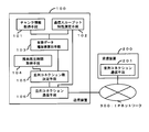
- FIG. FIG. 1 is a block diagram showing a configuration of a multimedia data communication system using a transmission apparatus according to the present invention. As illustrated in FIG. 1, the transmission device 100 is connected to the reception device 200 via a network 300.
- the transmission device 100 is an information processing device that transmits multimedia data stored in the media data 600 to the reception device 200 via the network 300.
- the transmission device 100 includes a central processing unit (CPU: Central Processing Unit) and a storage device (memory and HDD (Hard Disk Drive)) (not shown).
- CPU Central Processing Unit
- HDD Hard Disk Drive
- the transmission device 100 realizes functions to be described later when the CPU executes a program stored in the storage device.
- the transmission device 100 is, for example, a server device or a PC (Personal Computer), and is not particularly limited as long as parallel connection communication is possible.
- the receiving device 200 is an information processing device that receives and reproduces (displays) multimedia data transmitted from the transmitting device 100 via the network 300.
- the receiving device 200 includes a central processing unit (CPU), a storage device (for example, a memory and an HDD), and a display device (for example, a display) (not shown).
- the receiving device 200 realizes functions to be described later when the CPU executes a program stored in the storage device.
- the receiving device 200 may be, for example, a fixed information processing device such as a PC, or a mobile terminal.
- the network 300 is a network that performs communication based on a predetermined protocol. If the network 300 is, for example, an IP (Internet Protocol) network, various sub-networks around the world are connected by the IP of the third layer of the OSI (Open Systems Interconnection) reference model and spread worldwide. It is possible to communicate with various receiving devices.
- the network 300 may include a relay device such as a router (not shown).
- the network 300 may be realized by a wired communication network, but a part or all of the network 300 may be realized by a wireless communication network.
- the connection between the transmission device 100 and the network 300 and the connection between the reception device 200 and the network 300 are indicated by solid lines, but this means that the communication method is limited to the wired communication method.
- Arbitrary communications such as HSDPA (High Speed Downlink Packet Access), LTE (Long Term Evolution), Wi-Fi (Wireless Fidelity), etc. between the transmitting apparatus 100 and the network 300 and between the receiving apparatus 200 and the network 300 You may be connected by the radio
- the transmission device 100 transmits data to the reception device 200 via the network 300 according to TCP / IP, but may follow other protocols.
- FIG. 2 is a block diagram showing a specific configuration of the first embodiment of the system using the transmission device according to the present invention.
- the transmitting apparatus 100 includes a chunk information acquisition unit 101, a communication throughput characteristic measurement unit 102, an effective data increase rate calculation unit 103, a remaining reproduction time acquisition unit 104, and a parallel connection number determination unit 105. And parallel connection communication means 106.
- the chunk information acquisition unit 101 acquires the size of each chunk of multimedia data that the transmission device 100 transmits to the reception device 200.
- a chunk is a chunk of data.
- Multimedia data having a large size, such as a moving image or audio, is composed of a plurality of chunks, and is often transmitted and received in units of chunks. Also in this embodiment, it is assumed that multimedia data is transmitted and received in units of chunks.
- the communication throughput characteristic measuring unit 102 measures a communication throughput characteristic that is a communication performance when a parallel connection communication unit 106 described later transmits data from the transmission apparatus 100 to the reception apparatus 200 using one or a plurality of connections in parallel.
- a connection is a logical line when data transfer is performed, and corresponds to a TCP connection when TCP is used as a communication protocol.
- the parallel connection communication means 106 can communicate using a plurality of connections in parallel.
- the communication throughput characteristic is information indicating a probability distribution of communication throughput in each connection for each number of connections used for transmission of multimedia data, for example.
- the communication throughput characteristics are the average value of the communication throughput in each connection and the variation in the communication throughput in each connection for each number of connections used for transmission of multimedia data. Standard deviation is mentioned.
- the communication throughput characteristic may be any information as long as the information can obtain a probability distribution of communication throughput. Further, the communication throughput characteristic measuring unit 102 may acquire the communication throughput characteristic from the outside.
- FIG. 3 is an explanatory diagram showing an example of measurement results of communication throughput characteristics.
- the graph shown in FIG. 3 shows the relationship between the number of parallel connections and communication throughput. Specifically, FIG. 3 shows the total communication throughput, the average value of communication throughput in each connection, and the respective values when the number of parallel connections (hereinafter sometimes referred to as the number of connections) is increased from 1 to 8. It is the graph by which the standard deviation of the communication throughput fluctuation
- the average value of the communication throughput in each connection and the standard deviation of the fluctuation in communication throughput in each connection exist as many as the number of parallel connections, but are almost the same value in all connections. Only the strain is plotted.
- the communication throughput characteristic measuring unit 102 measures the communication throughput characteristic by, for example, performing test communication between the transmission apparatus 100 and the reception apparatus 200 while changing the number of parallel connections. Further, as described in Non-Patent Document 1, the communication throughput characteristic measuring unit 102 may calculate the communication throughput characteristic based on a mathematical model of communication throughput. The calculation of the communication throughput characteristic based on this mathematical model is premised on the communication by the TCP protocol, and is defined as the following formula (1).
- BW agg is the total bandwidth (communication throughput)
- MSS is the maximum number of segments
- C is a constant
- RTT the round trip time
- p the packet loss.
- the effective data increase rate calculation means 103 calculates an effective data increase rate that is an increase amount of effective data per unit time during a predetermined period based on the data size of each chunk and the communication throughput characteristics.
- the predetermined period is a period from a certain point in time until a predetermined elapsed time elapses.
- the effective data increase rate calculation unit 103 calculates an effective data rate for each connection and for each elapsed time.
- the valid data is reproducible data among the transmitted multimedia data, and will be described in detail later.
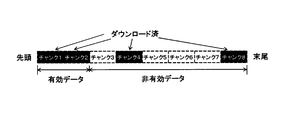
- FIG. 4 is an explanatory diagram showing examples of valid data and invalid data in multimedia data. Specifically, FIG. 4 shows that when the multimedia data divided into a plurality of chunks is transmitted in parallel using a plurality of connections, the reception device 200 has already received the chunk (black background portion) and the reception has not been performed yet. Represents an unfinished chunk (white background).
- the transmitting apparatus 100 When transmitting multimedia data in parallel using a plurality of connections, the transmitting apparatus 100 often transmits one chunk using one connection, and this embodiment will also be described based on that premise. Since the communication throughput of each connection varies depending on the network state during communication, the time until the reception device 200 completes reception of each chunk also varies. Therefore, the receiving apparatus 200 does not necessarily complete the reception of the chunks in order from 1, but may complete the reception discontinuously as 1, 2, 4, and 8 as shown in FIG.
- the reception-completed chunk 1 and chunk 2 can be played back by the receiving device because they are continuous chunks from the beginning (or playback start position).
- the chunk 4 and the chunk 8 cannot be reproduced because the chunk 3 has not been received yet.
- chunks that are continuous from the top of the received completion chunks are referred to as valid data.
- chunks that are not valid data among the chunks that have been received are referred to as non-valid data.
- FIG. 5 is an explanatory diagram showing a chunk transmission process when the number of parallel connections is four.
- the transmission device 100 transmits 12 chunks (each chunk is the same size) using four parallel connections (connection 1, connection 2, connection 3, and connection 4). It shows the relationship between the passage of time and the chunk transmission process. If the communication throughput of connection 1 and connection 4 is 1, the communication throughput of connection 2 is 2 (twice that of connection 1 and connection 4), and the communication throughput of connection 3 is 1/2 (half of connection 1 and connection 4). is there.
- the right triangle on the graph represents the transmission process of the corresponding chunk. The left vertex of the right triangle represents the transmission start time of the chunk, and the length of the base represents the time required to transmit the chunk.
- a straight line (broken line) indicated as “total communication throughput” indicates the total communication throughput of connection 1, connection 2, connection 3, and connection 4.
- the chunks that can be transmitted in the time required for connection 1 to transmit one chunk are: connection 1 is 1, connection 2 is 2, connection 3 is 1/2, Since connection 4 is 1, the total is 4.5 chunks. Therefore, the straight line indicated as “total communication throughput” is a straight line that increases by 4.5 chunks per base length of the right triangle of connection 1.
- a broken line (solid line) indicated as “valid data” indicates the size of the valid data described above, that is, a process of increasing the valid data.
- the straight line (dashed line) indicated as “reproduction consumption axis (real time axis)” is a straight line representing the relationship between the passage of time and the amount of chunks consumed by reproduction.
- the slope of the straight line of the playback consumption axis is a slope that increases by two chunks per time required for connection 1 to transmit one chunk.
- the straight line (two-dot chain line) of the “reproduction consumption axis without interruption” is a straight line that eliminates the situation where the broken line of valid data falls below the straight line by moving the reproduction consumption axis to the time axis side. If playback is started from the intersection of the playback consumption axis and the time axis without interruption, there is no need to delay cueing for buffering or playback interruption. That is, the distance in the time axis direction between the playback consumption axis (real time axis) and the continuous playback consumption axis indicates the waiting time required for buffering.
- the graph shown in FIG. 5 shows that even if the total communication throughput is improved using a plurality of parallel connections, there is a separation between the increase in effective data and the total communication throughput when a plurality of parallel connections are used. Show. Furthermore, the graph shown in FIG. 5 eliminates the cueing delay for buffering and disruption of playback if the increase in effective data does not exceed the playback consumption even if the total communication throughput greatly exceeds the playback consumption. Indicates that it is not possible. Thus, it can be understood that the effective data increase rate is important in streaming playback, not the total communication throughput, in order to eliminate cue delay and playback interruption.
- Effective data rate of increase y t by such chunk transmission is defined by the equation (2).
- time 0 is a predetermined time that is a base point of elapsed time
- time t is an end time of elapsed time.
- a 0 is the time (including reproduction completion, hereinafter the same) effective data size when it is 0 is
- a t is the effective data size at time t (> 0).
- the total communication throughput x t described above is expressed by formula (3).
- B 0 is the transmitted data size at time 0
- B t is the transmitted data size at time t (> 0).
- FIG. 6 is an explanatory diagram showing settings used to calculate the effective data increase rate using the Monte Carlo simulation.
- the simulation in this embodiment is performed using the chunk information (chunk size) acquired by the chunk information acquisition unit 101 and the communication throughput characteristic acquired by the communication throughput characteristic measurement unit 102.
- the communication throughput characteristics are, for example, an average value of communication throughput in each connection as shown in FIG. 6, and a standard deviation of communication throughput fluctuation in each connection.
- the probability distribution of the communication throughput of each connection is a Gaussian distribution
- the Gaussian distribution is determined by the average and variance (square of standard deviation) of the communication throughput obtained from the communication throughput characteristic measurement result. Therefore, the effective data increase rate calculation unit 103 can obtain a Gaussian distribution using the communication throughput characteristics.
- the effective data increase rate calculation means 103 executes the simulation a plurality of times by randomly setting the communication throughput in each connection based on the obtained Gaussian distribution. As shown in FIG. 5, if the chunk size of each chunk and the communication throughput in each connection are set, the effective data size can be calculated. Then, the effective data increase rate calculation means 103 can calculate the effective data increase rate using the calculated effective data size as shown in the equation (1). Note that the maximum value of t in the calculation of the effective data increase rate is, for example, the maximum value of the reproduction time of multimedia data to be reproduced. This is because the maximum value of the remaining reproduction time described later is the maximum value of the reproduction time of multimedia data.
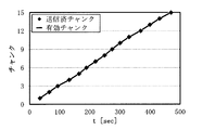
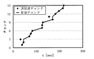
- FIG. 7 is an explanatory diagram showing the relationship between the transmitted chunks and valid chunks and the elapsed time when the number of parallel connections is 1.
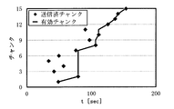
- FIG. 9 is an explanatory diagram showing the relationship between the transmitted chunks and valid chunks and the elapsed time when the number of parallel connections is two.
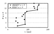
- FIG. 11 is an explanatory diagram showing the relationship between the transmitted chunks and valid chunks and the elapsed time when the number of parallel connections is three.
- FIG. 13 is an explanatory diagram showing the relationship between the transmitted chunks and valid chunks and the elapsed time when the number of parallel connections is four.
- FIG. 15 is an explanatory diagram showing the relationship between the transmitted chunks and valid chunks and the elapsed time when the number of parallel connections is five.
- FIG. 17 is an explanatory diagram showing the relationship between the transmitted chunks and valid chunks and the elapsed time when the number of parallel connections is six.
- FIG. 19 is an explanatory diagram showing the relationship between the transmitted chunks and valid chunks and the elapsed time when the number of parallel connections is seven.
- FIG. 21 is an explanatory diagram showing the relationship between the transmitted chunks and valid chunks and the elapsed time when the number of parallel connections is eight.
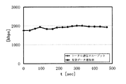
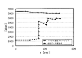
- FIG. 8 is an explanatory diagram showing the relationship between the total communication throughput and effective data increase rate and elapsed time when the number of parallel connections is one.
- FIG. 10 is an explanatory diagram showing the relationship between the total communication throughput and the effective data increase rate and the elapsed time when the number of parallel connections is two.
- FIG. 12 is an explanatory diagram showing the relationship between the total communication throughput and the effective data increase rate and the elapsed time when the number of parallel connections is three.
- FIG. 14 is an explanatory diagram showing the relationship between the total communication throughput and the effective data increase rate and the elapsed time when the number of parallel connections is four.
- FIG. 16 is an explanatory diagram showing the relationship between the total communication throughput and the effective data increase rate and the elapsed time when the number of parallel connections is five.
- FIG. 18 is an explanatory diagram showing the relationship between the total communication throughput and the effective data increase rate and the elapsed time when the number of parallel connections is six.
- FIG. 20 is an explanatory diagram showing the relationship between the total communication throughput and the effective data increase rate and the elapsed time when the number of parallel connections is seven.
- FIG. 22 is an explanatory diagram showing the relationship between the total communication throughput and the effective data increase rate and the elapsed time when the number of parallel connections is eight.
- the parallel connection number is plural (2 or more)
- a phenomenon that has been transmitted chunk does not arrive continuously from the head occurs, peeling occurs between the total communication throughput x t and the effective data rate of increase y t .
- the delamination between the total communication throughput x t and the effective data rate of increase y t is following features.
- the release of the total communication throughput x t and the effective data rate of increase y t (x t -y t) is large at t small sections is that the smaller the t is larger interval. This is because the average and variance does not depend on t when the difference between the transmission-data-size B t and the effective data size A t the (B t -A t) was considered as a random variable. Therefore, since the numerators of the two terms in the following formula (4) do not depend on t, the separation (x t ⁇ y t ) is large in a section where t is small, and the separation becomes small as t increases. Theoretically, peeling (x t ⁇ y t ) ⁇ 0 at t ⁇ ⁇ . This can be confirmed by referring to FIG. 8, FIG. 10, FIG. 12, FIG. 14, FIG. 16, FIG.
- the second feature, the peeling of the total communication throughput x t and the effective data rate of increase y t (x t -y t) becomes larger as the parallel connection number is increased is that the parallel connection number is more reduced smaller .
- the variation in the chunk number of the transmitted chunk increases as the number of parallel connections increases.
- FIGS. 7, 9, 11, 13, 15, 17, 19, and 21 the number of transmitted chunks increases steadily.
- the probability of completing transmission with a serial number from the beginning decreases. Therefore, the difference (B t ⁇ A t ) between the effective data size and the transmitted data size becomes large.
- Equation (3) the larger the number of parallel connections, the larger the numerator (B t ⁇ A t ) of the first term on the right side, so the total communication throughput x t and the effective data increase rate y t (X t ⁇ y t ) also increases.
- the graphs shown in FIGS. 7 to 22 are examples in the simulation.
- the effective data increase rate calculation means 103 of this embodiment calculates the expected value of the effective data increase rate with respect to the number of parallel connections by executing a large number of simulations.
- FIG. 23 to FIG. 30 show the results of calculating the average value of the change with respect to the elapsed time of the total communication throughput and the effective data increase rate by executing the above simulation 1000 times.
- 23 is when the number of connections is 1
- FIG. 24 is when the number of connections is 2
- FIG. 25 is when the number of connections is 3
- FIG. 26 is when the number of connections is 4
- FIG. 27 is when the number of connections is 5.
- 28 shows the results when the number of connections is 6
- FIG. 29 shows the results when the number of connections is 7
- FIG. 30 shows the results when the number of connections is 8.
- the total communication throughput is maximum when the number of parallel connections is 6, as shown in FIG.
- the effective data increase rate increases as the number of parallel connections increases as t increases.
- the number of parallel connections is 7 or 8
- the effective data increase rate is lower than when the number of parallel connections is 6 even if t increases. This result differs depending on the network communication environment and the like.
- the number of parallel connections increases, the possibility that the chunks to be transmitted will be in the reproduction order becomes low. That is, the above-described separation between the total communication throughput and the effective data increase rate becomes larger as a shorter time elapses.
- the probability that chunks arrive in the reproduction order is high, that is, the above-described separation is small, and the effective data increase rate is high. For example, considering the case where the number of parallel connections is 1, the arrival in the playback order is ensured, so that the effective data increase rate becomes the maximum after a short time.
- FIG. 31 is an explanatory diagram showing the relationship between the effective data increase rate and the elapsed time when the parallel connection is from 1 to 8. That is, FIG. 31 is a graph in which the effective data increase rate for each elapsed time shown in FIGS. 23 to 30 is summarized into one graph for each number of connections.
- the numbers in the graph shown in FIG. 31 indicate the number of connections.
- the number 0 ⁇ t ⁇ 32 the number of parallel connections is 1, when 32 ⁇ t ⁇ 36, the number of parallel connections is 2, when 36 ⁇ t ⁇ 42, the number of parallel connections is 3, and when 42 ⁇ t ⁇ 48, the number of parallel connections is parallel.
- the number of connections is 4, when 48 ⁇ t ⁇ 56, the number of parallel connections is 5, and when t ⁇ 56, the number of parallel connections is 6, the effective data increase rate is maximized.
- the effective data increase rate calculation means 103 calculates the effective data increase rate for each predetermined elapsed time in each parallel connection number using the Monte Carlo simulation as described above. Further, in the present embodiment, the effective data rate of increase calculation unit 103 is to calculate the effective data rate of increase using a Monte Carlo simulation, the communication throughput performance measure the transmitted data B t and the effective data A t and the chunk information You may calculate by analytical or numerical analysis based on a result.
- the remaining reproduction time acquisition unit 104 acquires the remaining reproduction time ⁇ that is the reproduction time of unreproduced data among the valid data received by the receiving device 200.
- the unreproduced data is valid data that has not been reproduced when the remaining reproduction time acquisition unit 104 acquires the remaining reproduction time ⁇ . For example, if the data size of unreproduced data among the received valid data is 15 Mbytes and the data is 3 Mbps video data, the reproduction time of the data is 40 seconds, so the remaining reproduction time ⁇ is 40 seconds.
- the remaining playback time acquisition unit 104 may receive a notification of the remaining playback time ⁇ from the receiving device 200 via the network 300, or may estimate without receiving a notification from the receiving device 200.
- the estimated value of the remaining reproduction time ⁇ is expressed as shown in Equation (5).
- T A is a reproduction time of valid data that has been transmitted by the transmitting apparatus 100 at the present time
- T 0 is an initial buffering time of the receiving apparatus 200
- T is an elapsed time from the start of transmission to the present time. .
- T 0 is a value that depends on the receiving apparatus 200
- the remaining reproduction time acquisition unit 104 needs to acquire T 0 in advance or assume an appropriate value.
- the parallel connection number determining means 105 is based on the effective data increase rate for each elapsed time in each parallel connection number calculated by the effective data increase rate calculating means 103 and the remaining reproduction time acquired by the remaining reproduction time acquiring means 104.
- the number of parallel connections used by parallel connection communication means 201 described later is determined. A method for determining the number of parallel connections will be described below.
- Effective data rate of increase y t as shown in equation (2) is a value that depends on the time t.
- the effective data increase rate with a small t focuses on the effective data increase rate with a short elapsed time (near future), and the effective data increase rate with a large t focuses on the effective data increase rate with a long elapsed time (distant future). It can be said that.
- the remaining reproduction time represents a reproduction time that can be continuously reproduced by the receiving apparatus 200 without interruption. From another point of view, this can be said to be the remaining time until reproduction is interrupted when the effective data does not increase due to a decrease in communication throughput or the like. Therefore, if the remaining reproduction time is short, the risk of disruption is high, and if the remaining reproduction time is long, it can be considered that there is a grace period until the disruption.
- FIG. 32 is a graph showing the relationship between the remaining reproduction time and the optimum number of parallel connections.
- the horizontal axis indicates the remaining reproduction time
- the vertical axis indicates the number of parallel connections that maximizes the effective data increase rate.
- the parallel connection number determining means 105 determines the optimum number of parallel connections according to the remaining reproduction time ⁇ based on the graph shown in FIG.
- the parallel connection communication unit 106 transmits multimedia data composed of a plurality of chunks to the receiving device 200 using a plurality of connections.
- the parallel connection communication means 106 uses the number of parallel connections determined by the parallel connection number determination means 105 as the number of connections used for communication, and transmits using one connection for one chunk. Further, as shown in FIG. 5, the parallel connection communication unit 106 immediately starts transmitting the chunk closest to the top of the untransmitted chunks in the connection where the transmission of the chunks is completed.
- the receiving apparatus 200 includes parallel connection communication means 201 as shown in FIG.
- the parallel connection communication unit 201 receives data transmitted from the transmission device 100 in parallel through a plurality of connections.
- FIG. 33 is a flowchart showing the operation of the transmission apparatus of this embodiment.
- the chunk information acquisition unit 101 acquires the size of each chunk of multimedia data that the transmission device 100 transmits to the reception device 200 (step S01).
- the communication throughput characteristic measuring unit 102 measures, for each connection number, the communication throughput characteristic when the parallel connection communication unit 106 transmits data from the transmission device 100 to the reception device 200 using one or a plurality of connections in parallel ( Step S02).
- the effective data increase rate calculating means 103 calculates the effective data increase rate for each connection and for each elapsed time based on the chunk data size and the communication throughput characteristics (step S03).
- the remaining reproduction time acquisition unit 104 acquires the remaining reproduction time ⁇ that is the reproduction time of unreproduced data among the valid data received by the receiving device 200 (step S04).
- the parallel connection number determining unit 105 determines the parallel connection based on the effective data increase rate for each connection and elapsed time calculated by the effective data increase rate calculating unit 103 and the remaining reproduction time acquired by the remaining reproduction time acquiring unit 104.
- the number of parallel connections used by the communication means 106 is determined (step S05).
- the parallel connection communication means 106 transmits multimedia data composed of a plurality of chunks to the receiving apparatus 200 using the number of parallel connections determined by the parallel connection number determination means 105 (step S06).
- the parallel connection communication unit 201 of the receiving device 200 receives data transmitted from the transmitting device 100 in parallel through a plurality of connections (step S07).
- step S01 the order of chunk information acquisition processing in step S01 and the measurement of communication throughput characteristics in step S02 may be first.
- the chunk information acquisition (step S01), the measurement of communication throughput characteristics (step S02), and the calculation of the effective data increase rate (step S03) are performed before the start of communication.
- the acquisition of the remaining reproduction time (step S04) and the determination of the number of parallel connections (step S05) are performed periodically before and during communication of multimedia data, for example. For example, when it is desired to reduce the number of times of changing the number of connections, the period of obtaining the remaining reproduction time (step S04) and determining the number of parallel connections (step S05) may be reduced. Alternatively, only the remaining reproduction time may be checked periodically, and the number of connections may be changed only when the remaining reproduction time is a predetermined value or less. In addition, the transmission device 100 may receive from the reception device 200 that the remaining reproduction time has become a predetermined value or less.
- the effective data increase rate is as expected, when the number of parallel connections is dynamically controlled by applying the transmission device 100 of the present embodiment, and when the number of parallel connections is fixedly 6 Considering the difference in cueing delay when the number of parallel connections is fixed to 1. As described above, this embodiment is based on the premise that the total communication throughput is maximized when the number of connections is six. Further, in the present embodiment, when the number of connections is 1, it is assumed that the effective data increase rate becomes the highest after a short time (30 seconds or less in the example shown in FIG. 31).
- FIG. 34 is an explanatory diagram showing the relationship between the effective data increase rate and the passage of time using the transmission apparatus of the present embodiment.
- the effective data increase rate is a curve (upper envelope) connecting the maximum values of the effective data increase rates of the number of connections in FIG. This is an approximate line.
- the function of the effective data increase rate shown in FIG. 34 (function related to t) is y opt (t).
- the effective data size that increases during ⁇ time is ⁇ ⁇ y opt ( ⁇ ).
- the reproducible time is ( ⁇ ⁇ y opt ( ⁇ )) / r.
- the cue time is a time during which reproduction interruption does not occur in the middle, that is, a waiting time provided so that the buffer amount does not become zero , ⁇ 0 so that z opt ( ⁇ ) in equation (6) does not become zero. Need to be set. As shown in Equation (6), the second term on the right side decreases as ⁇ 0 increases, and z opt ( ⁇ ) increases.
- the calculation result of the minimum waiting time ⁇ 0 at which z opt ( ⁇ ) does not become 0 or less is about 11. 6 seconds. This value is calculated by incrementing ⁇ 0 from 0 by ⁇ seconds, and finding ⁇ 0 when z opt ( ⁇ ) becomes 0 or more for all ⁇ for the first time.
- the calculation result of the minimum waiting time ⁇ 0 at which the reproduction buffer does not become 0 as described above is This is about 20.0 seconds. That is, the waiting time for cueing becomes longer than when the number of connections is controlled using the transmission device 100 of the present embodiment.
- the reproduction buffer becomes 0 any time no matter how much ⁇ 0 is increased, and the reproduction is interrupted. This is because when the number of connections is 1, the average throughput is only 1900 kbps, which is smaller than the video bit rate of 3 Mpbs.
- the transmission apparatus can reduce the delay in cueing and the reproduction interruption in the transmission of multimedia data.
- the multimedia data transmitting apparatus determines the number of parallel connections that maximizes the effective data increase rate according to the remaining reproduction time. Therefore, the multimedia data transmitting apparatus according to the present embodiment can reduce cue delay and playback interruption in streaming playback.
- FIG. 35 is a block diagram showing a configuration of a second embodiment of the system using the receiving device according to the present invention.
- the system using the receiving apparatus of this embodiment includes a transmitting apparatus 400, a network 300, and a receiving apparatus 500.
- the receiving device 500 includes a chunk information acquisition unit 501, a communication throughput characteristic measurement unit 502, an effective data increase rate calculation unit 503, a remaining reproduction time acquisition unit 504, a parallel connection number determination unit 505, and a parallel connection communication unit 506. Including.
- the reproduction time acquisition unit 104, the parallel connection number determination unit 505, the parallel connection number determination unit 105, the parallel connection communication unit 506, and the parallel connection communication unit 106 have substantially the same functions.
- the chunk information acquisition unit 501 receives the notification regarding the chunk information from the transmission device 400 via the network 300 because the chunk information to be acquired is the same as the chunk information acquisition unit 101 but the multimedia data exists on the transmission device 400 side. There is a need.
- the effective data increase rate calculation unit 503 has a function equivalent to that of the effective data increase rate calculation unit 103, but is effective based on reception of chunks, not based on transmission of chunks as in the effective data increase rate calculation unit 103. Calculate the data growth rate.
- the remaining playback time acquisition unit 504 has a function equivalent to that of the remaining playback time acquisition unit 104, but is included in the receiving device 500. Therefore, it is necessary to exchange the remaining playback time by communication like the remaining playback time acquisition unit 104. Absent.
- the parallel connection communication unit 506 requests the transmission apparatus 400 to transmit the multimedia data using the number of parallel connections determined by the parallel connection number determination unit 505, and receives the multimedia data using the number of parallel connections. To do.
- the transmission device 400 includes parallel connection communication means 401.
- the parallel connection communication unit 401 transmits multimedia data using the number of parallel connections requested from the parallel connection communication unit 506 of the receiving device 500.
- the operation of the receiving apparatus 500 of this embodiment is the same as that of the transmitting apparatus 100 of the first embodiment except for the above differences, and thus the description thereof is omitted.
- FIG. 36 is a block diagram showing the main part of the multimedia data communication apparatus according to the present invention.
- a multimedia data communication apparatus according to the present invention is a multimedia data communication apparatus that performs communication of multimedia data divided into a plurality of chunks using a plurality of connections in parallel, and the data size of each chunk of multimedia data
- a chunk information acquisition unit 701 for acquiring data, a communication throughput characteristic measurement unit 702 for acquiring communication throughput characteristics as communication performance when data is communicated using a plurality of connections in parallel, the data size of each chunk, and communication throughput Based on the characteristics, an effective data increase rate that is an increase amount per unit time of effective data that is reproducible data among the multimedia data that has been transmitted during a predetermined elapsed period is determined for each elapsed time and the Effective data increase rate calculation for each number of connections And a section 703.
- the multimedia data communication device and the effective data increase rate calculation device shown in the following (1) to (6) are also disclosed.
- a multimedia data communication apparatus (for example, the transmission apparatus 100 or the reception apparatus 500) that performs communication of multimedia data divided into a plurality of chunks using a plurality of connections in parallel, Acquires a communication throughput characteristic that is communication performance when data is communicated with a chunk information acquisition unit (for example, chunk information acquisition unit 101 or chunk information acquisition unit 501) that acquires the data size of a chunk and a plurality of connections in parallel.
- a chunk information acquisition unit for example, chunk information acquisition unit 101 or chunk information acquisition unit 501 that acquires the data size of a chunk and a plurality of connections in parallel.
- Communication throughput characteristic measurement means for example, communication throughput characteristic measurement means 102 or communication throughput characteristic measurement means 502
- the data size of each chunk and the communication throughput characteristic based on the transmitted elapses Multimedia day
- Effective data increase rate calculating means for obtaining an effective data increase rate that is an increase amount per unit time of effective data that is reproducible data for each elapsed time and each connection number (for example, effective data increase rate calculation)
- Multimedia data communication apparatus comprising means 103 or effective data increase rate calculation means 503).
- the multimedia data communication apparatus includes a residual playback time acquisition unit (for example, the residual playback time acquisition unit 104 or the residual playback time acquisition unit 504) that acquires a residual playback time that is a non-playback time of valid data, and an elapsed time.
- a parallel connection number determination means for example, parallel connection for inputting the effective data increase rate for each elapsed time and determining the number of connections used for transmission of multimedia data based on the effective data increase rate for each elapsed time and the remaining reproduction time
- the number determining means 105 or the parallel connection number determining means 505) may be provided.
- the multimedia data communication apparatus may be configured such that the communication throughput characteristic is information indicating a probability distribution of communication throughput in each connection for each number of connections used for transmitting multimedia data.
- the communication throughput characteristic is a normal distribution of probability distribution
- the average value of communication throughput in each connection for each number of connections used for transmission of multimedia data, and in each connection You may be comprised so that it may be a standard deviation of communication throughput.
- the effective data increase rate is a value obtained by dividing effective data, which is reproducible data among the transmitted multimedia data during a predetermined elapsed period, by the elapsed time. It may be configured to be.
- the multimedia data communication apparatus is configured such that the parallel connection number determining means determines to use the number of connections that maximizes the effective data increase rate when the elapsed time is replaced with the remaining reproduction time. Also good.
- An effective data increase rate calculating device used in a multimedia data communication device that performs communication of multimedia data divided into a plurality of chunks using a plurality of connections in parallel, and for each chunk of the multimedia data Chunk information acquisition means for acquiring data size (for example, chunk information acquisition means 101 or chunk information acquisition means 501) and communication for acquiring communication throughput characteristics, which is communication performance when data is communicated using a plurality of connections in parallel Based on the throughput characteristic measurement means (for example, the communication throughput characteristic measurement means 102 or the communication throughput characteristic measurement means 502), the data size of each chunk, and the communication throughput characteristic, the multimedia that has been transmitted during a predetermined elapsed period Re out of the data Effective data increase rate calculating means (for example, effective data increase rate calculating means 103 or 103) that obtains an effective data increase rate that is an increase amount per unit time of effective data that is possible data for each elapsed time and each number of connections.
- An effective data increase rate calculating device comprising effective data increase rate calculating means 503).
- the present invention can be applied to a server device that transmits multimedia data and a client device that views the data while receiving the data.
Landscapes
- Engineering & Computer Science (AREA)
- Multimedia (AREA)
- Computer Networks & Wireless Communication (AREA)
- Signal Processing (AREA)
- Two-Way Televisions, Distribution Of Moving Picture Or The Like (AREA)
- Data Exchanges In Wide-Area Networks (AREA)
Description
本発明は、複数のコネクションを並列に用いて動画や音声等のマルチメディアデータ通信を行う、送信装置、受信装置、マルチメディアデータ通信方法およびマルチメディアデータ通信プログラムに関する。
通信ネットワークを介してデータを受信しながら再生するストリーミング再生が、一般的に用いられている。動画等のマルチメディアデータが、ストリーミング再生によって再生される場合、頭出しの遅延や再生途絶が課題となる。頭出し(再生開始)の遅延および再生途絶は、ともに再生側におけるマルチメディアデータのバッファリング(バッファにデータを一時保存すること)に起因する。頭出しの遅延は、再生開始のためにある程度(例えば再生時間にして数秒分)のマルチメディアデータが再生側にバッファリング(初期バッファリング)されるまで再生が開始されないことにより生じる。再生途絶は、マルチメディアデータのバッファリング量が枯渇する(0になる)ことにより生じる。つまり、再生途絶は、再生により消費されるバッファリングされたマルチメディアデータの量が、受信によってバッファリングされるマルチメディアデータの量に到達することにより生じる。
上述した課題を解決するための複数のコネクションを並列に用いるマルチメディアデータ通信方法の一例が特許文献1に記載されている。特許文献1には、複数のコネクションを用いたデータ通信方法が開示されている。特許文献1に記載されているデータ通信方法は、複数のコネクションを用いてデータの異なる部分を並列に送信することにより、データ送信の効率(通信スループット)を向上させている。
また、特許文献2には、複数のコネクションを用いてデータを送信する際に、当該コネクション数を決定する方法が記載されている。特許文献2に記載されているコネクション数決定方法は、通信プロトコルであるTCP(Transmission Control Protocol)のウィンドウサイズとネットワーク往復遅延時間と回線速度とに基づいてコネクション数を決定することにより、送信効率(通信スループット)を向上させている。
Thomas J. Hacker、 Brian D. Athey、 "The End-to-End Performance Effects of Parallel TCP Sockets on a Lossy Wide-Area Network" Proc. of IPDPS、 2002.
上述した頭出しの遅延および再生途絶の原因の一つは、通信ネットワークを介して単位時間あたりに送受信できるデータ量である通信スループットが不足することである。通信スループットが不足すれば初期バッファリングに時間がかかるし、通信スループットが再生によるマルチメディアデータの消費量と比べて不足すれば再生途絶が生じる。
しかし、特許文献1や特許文献2に記載された技術をストリーミング再生に適用した場合、トータル通信スループットが向上しても頭出しの遅延および再生途絶の問題を解決できないことがある。この理由を以下に説明する。
マルチメディアデータのストリーミング再生において、再生を行う受信装置は、マルチメディアデータの先頭(もしくは再生開始位置)から順番に消費していく必要がある。上記技術により、送信装置が、マルチメディアデータを複数のチャンクに分割し、各チャンクを複数のコネクションを用いて並列に送信することによってトータル通信スループットを向上させることができる。しかし、受信済みチャンクをマルチメディアデータに復元したときにその並びにおいて途中に未だ受信していないデータが存在する場合、受信装置は、未だ受信していないデータの後方に位置する受信済みデータを再生することができない。
よって、特許文献1や特許文献2に記載された技術は、頭出しの遅延および再生途絶という課題の解決には不十分である。
そこで、本発明は、ストリーミング再生における頭出しの遅延および再生途絶を低減させることができるマルチメディアデータ通信装置、方法、プログラムおよび有効データ増加率算出装置を提供することを目的とする。
本発明によるマルチメディアデータ通信装置は、複数のコネクションを並列に用いて複数のチャンクに分割されたマルチメディアデータの通信を行うマルチメディアデータ通信装置であって、マルチメディアデータの各チャンクのデータサイズを取得するチャンク情報取得手段と、複数のコネクションを並列に用いてデータを通信するとき通信性能である通信スループット特性を取得する通信スループット特性測定手段と、各チャンクのデータサイズ、および通信スループット特性に基づいて、所定の経過期間中における、送信済みのマルチメディアデータのうち再生可能なデータである有効データの単位時間あたりの増加量である有効データ増加率を、当該経過時間毎およびコネクション数毎に求める有効データ増加率算出手段とを備えたことを特徴とする。
本発明によるマルチメディアデータ通信方法は、複数のコネクションを並列に用いて複数のチャンクに分割されたマルチメディアデータの通信を行うマルチメディアデータ通信方法であって、マルチメディアデータの各チャンクのデータサイズを取得し、複数のコネクションを並列に用いてデータを通信するとき通信性能である通信スループット特性を取得し、各チャンクのデータサイズ、および通信スループット特性に基づいて、所定の経過期間中における、送信済みのマルチメディアデータのうち再生可能なデータである有効データの単位時間あたりの増加量である有効データ増加率を、当該経過時間毎およびコネクション数毎に求めることを特徴とするマルチメディアデータ通信方法。
本発明によるマルチメディアデータ通信プログラムは、コンピュータに、複数のコネクションを並列に用いて複数のチャンクに分割されたマルチメディアデータの通信を行わせるマルチメディアデータ通信プログラムであって、コンピュータに、マルチメディアデータの各チャンクのデータサイズを取得するチャンク情報取得処理と、複数のコネクションを並列に用いてデータを通信するとき通信性能である通信スループット特性を取得する通信スループット特性測定処理と、各チャンクのデータサイズ、および通信スループット特性に基づいて、所定の経過期間中における、送信済みのマルチメディアデータのうち再生可能なデータである有効データの単位時間あたりの増加量である有効データ増加率を、当該経過時間毎およびコネクション数毎に求める有効データ増加率算出処理とを実行させることを特徴とする。
本発明による有効データ増加率算出装置は、複数のコネクションを並列に用いて複数のチャンクに分割されたマルチメディアデータの通信を行うマルチメディアデータ通信装置に用いられる有効データ増加率算出装置であって、マルチメディアデータの各チャンクのデータサイズを取得するチャンク情報取得手段と、複数のコネクションを並列に用いてデータを通信するとき通信性能である通信スループット特性を取得する通信スループット特性測定手段と、各チャンクのデータサイズ、および通信スループット特性に基づいて、所定の経過期間中における、送信済みのマルチメディアデータのうち再生可能なデータである有効データの単位時間あたりの増加量である有効データ増加率を、当該経過時間毎およびコネクション数毎に求める有効データ増加率算出手段とを備えたことを特徴とする。
本発明は、ストリーミング再生における頭出しの遅延および再生途絶を低減させることができる。
次に、本発明の実施形態を、図面を参照して説明する。
実施形態1.
図1は、本発明による送信装置を用いたマルチメディアデータ通信システムの構成を示すブロック図である。図1に示すように、送信装置100は、ネットワーク300を介して受信装置200に接続されている。
図1は、本発明による送信装置を用いたマルチメディアデータ通信システムの構成を示すブロック図である。図1に示すように、送信装置100は、ネットワーク300を介して受信装置200に接続されている。
送信装置100は、メディアデータ600に保存されたマルチメディアデータを、ネットワーク300を介して受信装置200へ送信する情報処理装置である。送信装置100は、図示しない中央処理装置(CPU:Central Processing Unit)、および、記憶装置(メモリおよびHDD(Hard Disk Drive))を備える。送信装置100は、記憶装置に記憶されているプログラムをCPUが実行することにより、後述する機能を実現する。送信装置100は、例えばサーバ装置またはPC(Personal Computer)等であり、並列コネクション通信が可能なものならば特に限定されない。
受信装置200は、ネットワーク300を介して送信装置100から送信されたマルチメディアデータを受信して再生(表示)する情報処理装置である。受信装置200は、図示しない中央処理装置(CPU)、記憶装置(例えば、メモリおよびHDD)、表示装置(例えば、ディスプレイ)を備える。受信装置200は、記憶装置に記憶されているプログラムをCPUが実行することにより、後述する機能を実現する。受信装置200は、例えば、PC等の固定された情報処理装置であってもよいし、または携帯端末であってもよい。
ネットワーク300は、所定のプロトコルに準拠した通信を行うネットワークである。ネットワーク300は、例えば、IP(Internet Protocol)ネットワークであれば、世界中の様々なサブネットワークをOSI(Open Systems Interconnection)参照モデルの第3層のIPにより結合して、世界的に広がっているため、様々な受信装置と通信可能である。ネットワーク300は、例えば図示しないルータ等の中継装置等を含んでいてもよい。
また、ネットワーク300は、有線通信網により実現されてもよいが、その一部又は全部が無線通信網により実現されてもよい。なお、図1では送信装置100とネットワーク300との間、および受信装置200とネットワーク300との間の接続は、実線で記載されているが、通信方式を有線通信方式に限定することを意味するのではない。送信装置100とネットワーク300との間、および受信装置200とネットワーク300との間は、HSDPA(High Speed Downlink Packet Access)やLTE(Long Term Evolution)やWi-Fi(Wireless Fidelity)等の任意の通信方式に準拠した無線通信網により接続されていてもよい。
また、本実施形態では、送信装置100は、ネットワーク300を介して、TCP/IPに従って、受信装置200へデータを送信するが、その他のプロトコルに従ってもよい。
図2は、本発明による送信装置を用いたシステムの第1の実施形態の具体的な構成を示すブロック図である。図2に示すように、送信装置100は、チャンク情報取得手段101と、通信スループット特性測定手段102と、有効データ増加率算出手段103と、残余再生時間取得手段104と、並列コネクション数決定手段105と、並列コネクション通信手段106とを含む。
チャンク情報取得手段101は、送信装置100が受信装置200へ送信するマルチメディアデータの各チャンクのサイズを取得する。チャンクとは、ひとまとまりのデータの塊である。動画や音声等のサイズが大きなマルチメディアデータは、複数のチャンクから構成されており、しばしばチャンク単位で送受信が行われる。本実施形態でも、マルチメディアデータは、チャンク単位で送受信されることを前提とする。
例えば、マルチメディアデータがn個のチャンクから構成されており、各チャンクのサイズがそれぞれs1、s2、…、sn[byte]である場合、チャンク情報取得手段101は、その集合{si(i=1、2、…n)}を取得する。
通信スループット特性測定手段102は、後述する並列コネクション通信手段106が送信装置100から受信装置200へ1つまたは複数のコネクションを並列に用いてデータを送信するときの通信性能である通信スループット特性を測定する。コネクションとは、データ転送が行われる際の論理的な回線のことであり、通信プロトコルとしてTCPが用いられる場合、TCPコネクションに相当する。並列コネクション通信手段106は、複数のコネクションを並列に用いて通信することができる。ここで、通信スループット特性とは、例えば、マルチメディアデータの送信に用いられるコネクション数毎の、各コネクションにおける通信スループットの確率分布を示す情報である。具体例としては、確率分布が正規分布であれば、通信スループット特性は、マルチメディアデータの送信に用いられるコネクション数毎の、各コネクションにおける通信スループットの平均値、および各コネクションでの通信スループット変動の標準偏差が挙げられる。なお、通信スループット特性は、通信スループットの確率分布が得られる情報であればどのような情報であってもよい。また、通信スループット特性測定手段102は、通信スループット特性を外部から取得してもよい。
図3は、通信スループット特性の測定結果の一例を示した説明図である。図3に示されるグラフは、並列コネクション数と通信スループットとの関係を示している。図3は、具体的には、並列コネクション数(以下、コネクション数と記載されることがある)を1から8まで増加させたときの、トータル通信スループット、各コネクションにおける通信スループットの平均値、各コネクションでの通信スループット変動の標準偏差がプロットされたグラフである。各コネクションにおける通信スループットの平均値、各コネクションでの通信スループット変動の標準偏差は、並列コネクション数の分だけ存在するが、全てのコネクションでほぼ同一の値であるので、グラフでは代表してそれぞれ1系統だけプロットされている。ほぼ同一の値である理由は、本実施形態では全てのコネクションが同一物理回線、同一プロトコルで構成されているためである。なお、本実施形態で用いられる通信回線は、インターネットにFTTH(Fiber To The Home)とWi-Fiで接続されたものであり、プロトコルは、TCPとする。また、全てのコネクションは、必ずしも同一物理回線、同一プロトコルで構成されていなくてもよい。
図3に示す測定結果では、並列コネクション数が6以下の場合、並列コネクション数の増加に対してトータル通信スループットは単調増加しているが、並列コネクション数が6より大きい場合、並列コネクション数の増加に対してトータル通信スループットが単調に減少している。すなわち、並列コネクション数に対するトータル通信スループットは、上に凸の形状を成し、トータル通信スループットが最大となるコネクション数が存在する。このように、トータル通信スループットは、はじめは並列コネクション数の増加に伴って増加していくが、必ず頭打ちになることが一般的に知られている。
通信スループット特性測定手段102は、例えば、送信装置100と受信装置200との間で並列コネクション数を変化させて試験通信することで通信スループット特性を測定する。また、通信スループット特性測定手段102は、非特許文献1に記載されているように、通信スループットの数学モデルに基づいて通信スループット特性を計算してもよい。この数学モデルに基づく通信スループット特性の計算は、TCPプロトコルによる通信を前提としており、以下の式(1)のように定義される。式(1)において、BWaggは総帯域幅(通信スループット)であり、MSSは最大セグメント数であり、Cは定数であり、RTTは往復時間であり、pはパケット損失である。

有効データ増加率算出手段103は、各チャンクのデータサイズと、通信スループット特性とに基づいて、所定の期間中における、単位時間あたりの有効データの増加量である有効データ増加率を算出する。所定の期間とは、ある時点から所定の経過時間が経過するまでの期間をいう。なお、本実施形態では、有効データ増加率算出手段103は、コネクション毎および経過時間毎に有効データ率を求める。有効データとは、送信したマルチメディアデータのうち再生可能なデータであり、詳しくは後述する。
図4は、マルチメディアデータにおける有効データと非有効データの例を示す説明図である。図4は、具体的には、複数のチャンクに分割されたマルチメディアデータを複数のコネクションを用いて並列に送信した場合の、受信装置200が受信済であるチャンク(黒地部分)と未だ受信が完了していないチャンク(白地部分)を表している。送信装置100は、マルチメディアデータを複数のコネクションを用いて並列に送信する場合、一つのチャンクを一つのコネクションで送信することが多く、本実施形態でもその前提で説明する。各コネクションの通信スループットは、通信中のネットワーク状態によって変動するため、受信装置200が各チャンクを受信完了するまでの時間も変動する。そのため、受信装置200は、チャンクを1から順番に受信完了するとは限らず、図4に示すように1、2、4、8と不連続に受信完了する場合がある。
この場合、受信完了済チャンク1およびチャンク2は、先頭(もしくは再生開始位置)から連続したチャンクであるため受信装置にて再生可能である。一方、チャンク4およびチャンク8はチャンク3が未だ受信完了済ではないため、再生不可能である。以下の説明では、前述のように受信完了済チャンクのうち先頭から連続したチャンクを、有効データという。また、受信完了済チャンクのうち有効データではないチャンクを、非有効データという。
マルチメディアデータのストリーミング再生では、前述の有効データの増加率が重要である。図5は、並列コネクション数が4のときのチャンク送信過程を示す説明図である。図5は、具体的には、送信装置100が、4つの並列コネクション(コネクション1、コネクション2、コネクション3、コネクション4)を用いて12個のチャンク(各チャンクは全て同じサイズである)を送信したときの時刻経過とチャンク送信過程との関係を示している。コネクション1とコネクション4の通信スループットを1とすると、コネクション2の通信スループットは2(コネクション1およびコネクション4の2倍)、コネクション3の通信スループットは1/2(コネクション1およびコネクション4の半分)である。グラフ上の直角三角形は、該当するチャンクの送信過程を表している。直角三角形の左頂点が当該チャンクの送信開始時刻を表し、底辺の長さがそのチャンクを送信するのに要した時間を表している。
始めに、コネクション1、コネクション2、コネクション3、コネクション4において、同時にチャンク1、チャンク2、チャンク3、チャンク4の送信がそれぞれ開始される。その後、当該チャンクの送信が完了したコネクションにおいて、未送信チャンクのうち最も先頭に近い(番号が若い)チャンクが送信され、以降その動作が繰り返される。例えば、コネクション2に着目すると、1つ目のチャンク(チャンク2)の送信が最も速く完了するため、その次に未送信チャンクのうち最も先頭に近いチャンク5の送信が開始される。次に、コネクション2においてチャンク5の送信が完了した時点で、チャンク6、チャンク7は、それぞれコネクション1、コネクション4において送信が開始されるので、コネクション2では、その次のチャンク8の送信が開始される。
また、図5において、「トータル通信スループット」と示された直線(破線)は、コネクション1、コネクション2、コネクション3、コネクション4の通信スループットの合計を示している。例えば、コネクション1が一つのチャンクを送信するのに要する時間(コネクション1の直角三角形の底辺の長さ)で送信できるチャンクは、コネクション1が1、コネクション2が2、コネクション3が1/2、コネクション4が1なので、合計は4.5チャンク分である。そのため、「トータル通信スループット」と示された直線は、コネクション1の直角三角形の底辺の長さあたり4.5チャンク分増加する直線となっている。「有効データ」と示された折れ線(実線)は、上述した有効データのサイズを示し、すなわち有効データの増加の過程を示している。
また、「再生消費軸(実時間軸)」と示された直線(一点鎖線)は、時間経過と再生により消費するチャンクの量の関係を表した直線である。図5では、コネクション1が一つのチャンクを送信するために要する時間あたり二つのチャンクを、再生により消費することを前提としている。再生消費軸の直線の傾きは、コネクション1が一つのチャンクを送信するのに要する時間あたりにチャンク二つ分増加する傾きである。図5では、有効データの折れ線が再生消費軸の直線の下になっている部分がある。この部分の存在は、有効データの増加が再生消費に追いついていないことを示しており、有効データをバッファリングするために待ち(頭出し遅延や再生途絶)が必要であることを示している。
「途絶なし再生消費軸」の直線(二点鎖線)は、再生消費軸を時刻軸側に平行移動することにより有効データの折れ線が当該直線を下回る状況をなくした直線である。途絶なし再生消費軸と時刻軸の交点から再生を開始すれば、バッファリングのための頭出し遅延や再生途絶が不要となる。つまり、再生消費軸(実時間軸)と途絶なし再生消費軸との時刻軸方向の距離が、バッファリングに必要な待ち時間を示している。
図5に示すグラフは、複数の並列コネクションを用いてトータル通信スループットを向上させたとしても、複数の並列コネクションを用いた場合は有効データの増加とトータル通信スループットとの間に剥離が生じることを示している。さらに、図5に示すグラフは、トータル通信スループットが再生消費量を大きく上回ったとしても、有効データの増加量が再生消費量を上回らないと、バッファリングのための頭出し遅延や再生途絶を解消できないことを示している。このように、頭出し遅延や再生途絶の解消のためには、ストリーミング再生においてトータル通信スループットではなく、有効データの増加率が重要であることが分かる。
このようなチャンク送信による有効データ増加率ytは、式(2)のように定義される。式(2)において、時刻0は、経過時間の基点となる所定の時刻であり、時刻tは、経過時間の終了時刻である。また、A0は時刻が0である場合の有効データサイズ(再生済を含む、以下同様)であり、Atは時刻t(>0)における有効データサイズであるとする。

一方、前述のトータル通信スループットxtは、式(3)のように表される。式(3)において、B0が時刻0における送信済データサイズ、Btが時刻t(>0)における送信済データサイズである。

有効データ増加率算出手段103は、マルチメディアデータの送信に用いる並列コネクション数毎に、および所定の経過時間毎に、上述した有効データ増加率yt(t=1,・・・,n)を算出する。本実施形態では、モンテカルロシミュレーションを用いた算出方法を説明する。
まず、本実施形態でのシミュレーション条件を説明する。図6は、モンテカルロシミュレーションを用いた有効データ増加率の算出に用いる設定を示す説明図である。本実施形態におけるシミュレーションは、チャンク情報取得手段101が取得したチャンク情報(チャンクサイズ)と、通信スループット特性測定手段102が取得した通信スループット特性を用いて行われる。通信スループット特性は、例えば、図6に示すような各コネクションにおける通信スループットの平均値、各コネクションでの通信スループット変動の標準偏差である。各コネクションの通信スループットの確率分布が、ガウス分布になると仮定するとそのガウス分布は、前記通信スループット特性測定結果から得られる通信スループットの平均および分散(標準偏差の2乗)により定められる。よって、有効データ増加率算出手段103は、通信スループット特性を用いてガウス分布を得ることができる。
そして、有効データ増加率算出手段103は、得られたガウス分布に基づき、各コネクションにおける通信スループットをランダムに設定してシミュレーションを複数回実施する。図5に示したように、各チャンクのチャンクサイズと各コネクションにおける通信スループットが設定されれば、有効データサイズを算出することが可能である。そして、有効データ増加率算出手段103は、式(1)に示したように、算出された有効データサイズを用いて、有効データ増加率を算出することができる。なお、有効データ増加率の算出におけるtの最大値は、例えば、再生されるマルチメディアデータの再生時間の最大値とする。その理由は、後述する残余再生時間の最大値がマルチメディアデータの再生時間の最大値だからである。
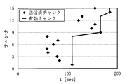
このシミュレーションにおける送信済みチャンク(Bt)および有効データ(チャンク)(At)と経過時間tとの関係は、図7、図9、図11、図13、図15、図17、図19、図21に示されている。図7は、並列コネクション数が1のときの送信済みチャンクおよび有効チャンクと経過時間との関係を示した説明図である。図9は、並列コネクション数が2のときの送信済みチャンクおよび有効チャンクと経過時間との関係を示した説明図である。図11は、並列コネクション数が3のときの送信済みチャンクおよび有効チャンクと経過時間との関係を示した説明図である。図13は、並列コネクション数が4のときの送信済みチャンクおよび有効チャンクと経過時間との関係を示した説明図である。図15は、並列コネクション数が5のときの送信済みチャンクおよび有効チャンクと経過時間との関係を示した説明図である。図17は、並列コネクション数が6のときの送信済みチャンクおよび有効チャンクと経過時間との関係を示した説明図である。図19は、並列コネクション数が7のときの送信済みチャンクおよび有効チャンクと経過時間との関係を示した説明図である。図21は、並列コネクション数が8のときの送信済みチャンクおよび有効チャンクと経過時間との関係を示した説明図である。
また、トータル通信スループットxtおよび有効データ増加率ytとtとの関係は、図8、図10、図12、図14、図16、図18、図20、図22に示されている。図8は、並列コネクション数が1のときのトータル通信スループットおよび有効データ増加率と経過時間との関係を示した説明図である。図10は、並列コネクション数が2のときのトータル通信スループットおよび有効データ増加率と経過時間との関係を示した説明図である。図12は、並列コネクション数が3のときのトータル通信スループットおよび有効データ増加率と経過時間との関係を示した説明図である。図14は、並列コネクション数が4のときのトータル通信スループットおよび有効データ増加率と経過時間との関係を示した説明図である。図16は、並列コネクション数が5のときのトータル通信スループットおよび有効データ増加率と経過時間との関係を示した説明図である。図18は、並列コネクション数が6のときのトータル通信スループットおよび有効データ増加率と経過時間との関係を示した説明図である。図20は、並列コネクション数が7のときのトータル通信スループットおよび有効データ増加率と経過時間との関係を示した説明図である。図22は、並列コネクション数が8のときのトータル通信スループットおよび有効データ増加率と経過時間との関係を示した説明図である。
なお、図8では、トータル通信スループットxtおよび有効データ増加率ytを示す線が重複している。また、図7から図22では、対象のマルチメディアは3Mbps、チャンクサイズ7.5MByte(再生時間は20秒分(3Mbps×20sec=60Mbit=7.5MByte))の動画コンテンツと仮定した結果を示している。
図8に示すように、並列コネクション数が1の場合は、送信済チャンクと有効データは一致するため、トータル通信スループットと有効データ増加率も一致する。しかし、並列コネクション数が複数(2以上)になると、送信済チャンクが先頭から連続して到着しない現象が発生するため、トータル通信スループットxtと有効データ増加率ytとの間に剥離が生じる。このトータル通信スループットxtと有効データ増加率ytとの間の剥離には次に示す特徴がある。
第一の特徴は、トータル通信スループットxtと有効データ増加率ytとの剥離(xt-yt)はtが小さい区間では大きく、tが大きい区間では小さくなることである。この理由は、送信済データサイズBtと有効データサイズAtとの差(Bt-At)を確率変数と考えたときにその平均や分散がtに依らないためである。そのため、以下の式(4)における二つの項の分子がtに依存しないため、剥離(xt-yt)はtが小さい区間では大きく、tが増加すると剥離は小さくなる。理論的にはt→∞において、剥離(xt-yt)→0となる。このことは、図8、図10、図12、図14、図16、図18、図20、図22を参照することにより確認することができる。

第二の特徴は、トータル通信スループットxtと有効データ増加率ytとの剥離(xt-yt)は、並列コネクション数が大きくなるほど大きくなり、並列コネクション数が小さくなるほど小さくなることである。この理由は、送信済チャンクのチャンク番号のばらつきが、並列コネクション数が大きくなるほど大きくなるためである。この事実は、図7、図9、図11、図13、図15、図17、図19、図21を参照することにより確認することができる。特に図17、図19、図21では、送信済チャンクは着実に増加していくが、並列コネクション数が大きいと先頭からの連番で送信完了する確率は低くなる。そのため、有効データサイズと送信済データサイズの差(Bt-At)は大きくなる。その結果、式(3)に表されるように、並列コネクション数が大きいほど右辺第1項の分子(Bt-At)が大きくなるため、トータル通信スループットxtと有効データ増加率ytとの剥離(xt-yt)も大きくなる。
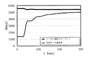
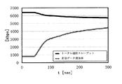
図7~図22に示したグラフは、シミュレーションにおける一例であった。本実施形態の有効データ増加率算出手段103は、このシミュレーションを数を多く実行することにより、並列コネクション数に対する有効データ増加率の期待値を算出する。図23~図30は、上述のシミュレーションを1000回ずつ実行してトータル通信スループットおよび有効データ増加率の経過時間に対する変化の平均値を算出した結果を示している。図23はコネクション数が1のとき、図24はコネクション数が2のとき、図25はコネクション数が3のとき、図26はコネクション数が4のとき、図27はコネクション数が5のとき、図28はコネクション数が6のとき、図29はコネクション数が7のとき、図30はコネクション数が8のときにおける結果である。なお、図23では、トータル通信スループットおよび有効データ増加率を示す線が重複している。
トータル通信スループットは、図3に示したとおり、並列コネクション数が6のときに最大となる。一方、有効データ増加率は、並列コネクション数が6以下の場合、tが大きくなるにつれて並列コネクション数が大きいほど有効データ増加率が高い。そして、並列コネクション数が7、8の場合、tが大きくなっても有効データ増加率は、並列コネクション数が6の場合よりも低い。なお、この結果は、ネットワークの通信環境等により異なる。
tが所定値より小さい区間においては、並列コネクション数が小さいほど有効データ増加率が高くなる理由を説明する。短い時間経過で考えた場合、並列コネクション数が大きくなると、送信完了するチャンクが再生順番通りとなる可能性が低くなる。すなわち前述したトータル通信スループットと有効データ増加率との剥離が、短い時間経過であるほど大きくなる。また、並列コネクション数が小さいと、チャンクが再生順番通りに到着する確率が高く、すなわち前述の剥離が小さくなるため、有効データ増加率が高くなる。例えば、並列コネクション数が最も小さい1の場合を考えると、確実に再生順番通りの到着となるため、短い時間経過では有効データ増加率が最大となる。一方、時間経過が長い場合、トータル通信スループットが大きいほど、送信完了したチャンク数が大きくなる。その場合、並列コネクション数だけ前述の剥離が存在するが、その剥離は長時間送信した多数のチャンクのうちの最後の部分に存在するものであり、頭出しや再生途絶にあまり影響を及ぼさない。したがって、長い時間経過で考えた場合はトータル通信スループットが大きいほど、有効データ増加率は高くなる。
図31は、並列コネクションが1から8の場合の有効データ増加率と経過時間の関係を示した説明図である。つまり、図31は、図23から図30に示された経過時間毎の有効データ増加率をコネクション数毎に一つのグラフにまとめたグラフである。図31に示すグラフ内の数字は、コネクション数を示している。数字0<t<32では並列コネクション数が1のとき、32≦t<36では並列コネクション数が2のとき、36≦t<42では並列コネクション数が3のとき、42≦t<48では並列コネクション数が4のとき、48≦t<56では並列コネクション数が5のとき、t≧56では並列コネクション数が6のときに、有効データ増加率が最大になることが分かる。
有効データ増加率算出手段103は、上述したようにモンテカルロシミュレーションを用いて各並列コネクション数における所定の経過時間毎の有効データ増加率を算出する。また、本実施形態では、有効データ増加率算出手段103は、モンテカルロシミュレーションを用いて有効データ増加率を算出したが、送信済みデータBtと有効データAtを前記チャンク情報と前記通信スループット特性測定結果に基づいて解析的もしくは数値解析によって算出してもよい。
残余再生時間取得手段104は、受信装置200が受信した有効データのうち未再生分のデータの再生時間である残余再生時間τを取得する。なお、未再生分のデータとは、残余再生時間取得手段104が残余再生時間τを取得する時点で再生されていない有効データである。例えば、受信した有効データのうち未再生分のデータのデータサイズが15MByteあり、当該データが3Mbpsの動画データであれば、当該データの再生時間は40秒分であるから、残余再生時間τは、40秒となる。
残余再生時間取得手段104は、受信装置200からネットワーク300を経由して残余再生時間τの通知を受けてもよいし、受信装置200から通知を受けずに推定してもよい。その場合、残余再生時間τの推定値は、式(5)のように表される。式(5)において、現時点において送信装置100が送信完了した有効データの再生時間をTA、受信装置200の初期バッファリングの時間をT0、送信開始時から現時点までの経過時間をTとする。
τ=TA-(T-T0) ・・・(5)
ただし、T0は、受信装置200に依存する値なので、残余再生時間取得手段104は、T0を予め取得するか、適当な値を仮定しておく必要がある。
並列コネクション数決定手段105は、有効データ増加率算出手段103が算出した各並列コネクション数における経過時間毎の有効データ増加率と、残余再生時間取得手段104が取得した残余再生時間とに基づいて、後述する並列コネクション通信手段201が用いる並列コネクション数を決定する。以下に、並列コネクション数を決定する方法を説明する。
式(2)に示した有効データ増加率ytは、時間tに依存する値である。tが小さい有効データ増加率は短い経過時間(近い将来)での有効データ増加率に着目しており、tが大きい有効データ増加率は長い経過時間(遠い将来)での有効データ増加率に着目したものといえる。
ところで、残余再生時間とは、受信装置200にて途絶なく連続的に再生できる再生時間を表している。これは、別の見方をすれば、以後通信スループットの低下等が原因で有効データが増加しない場合、再生が途絶するまでの残り時間であるとも言える。したがって、残余再生時間が短ければ途絶の危険性が高く、残余再生時間が長ければ途絶まで猶予があると考えることができる。
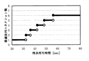
したがって、残余再生時間がτRのとき、それまでの期間中(すなわち、現時点からτR経過するまでの期間中)における有効データ増加率yτRが最大になる並列コネクション数で送信すれば、再生の途絶の可能性を低減することができる。図32は、残余再生時間と最適な並列コネクション数との関係を示したグラフである。図32は、横軸に残余再生時間、縦軸に有効データ増加率が最大となる並列コネクション数を示している。並列コネクション数決定手段105は、図32に示すグラフに基づいて、残余再生時間τに応じて最適な並列コネクション数を決定する。
並列コネクション通信手段106は、複数のコネクションを用いて、複数のチャンクから構成されたマルチメディアデータを受信装置200へ送信する。並列コネクション通信手段106は、通信に用いるコネクションの数として、並列コネクション数決定手段105が決定した並列コネクション数を用い、一つのチャンクに対して一つのコネクションを用いて送信する。また、並列コネクション通信手段106は、図5に示したようにチャンクの送信が完了したコネクションでは直ちに未送信のチャンクのうち最も先頭に近いチャンクの送信を開始する。
受信装置200は、図2に示すように、並列コネクション通信手段201を含む。並列コネクション通信手段201は、送信装置100から複数のコネクションで並列に送信されたデータを受信する。
次に、本実施形態の送信装置の動作を説明する。図33は、本実施形態の送信装置の動作を示すフローチャートである。
始めに、チャンク情報取得手段101は、送信装置100が受信装置200へ送信するマルチメディアデータの各チャンクのサイズを取得する(ステップS01)。通信スループット特性測定手段102は、並列コネクション通信手段106が送信装置100から受信装置200に1つまたは複数のコネクションを並列に用いてデータを送信するときの通信スループット特性をコネクション数毎に測定する(ステップS02)。
有効データ増加率算出手段103は、チャンクのデータサイズと、通信スループット特性とに基づいて、コネクション毎および経過時間毎の有効データ増加率を算出する(ステップS03)。
残余再生時間取得手段104は、受信装置200が受信した有効データのうち未再生分のデータの再生時間である残余再生時間τを取得する(ステップS04)。並列コネクション数決定手段105は、有効データ増加率算出手段103が算出したコネクション毎および経過時間毎の有効データ増加率と、残余再生時間取得手段104が取得した残余再生時間とに基づいて、並列コネクション通信手段106が用いる並列コネクション数を決定する(ステップS05)。
並列コネクション通信手段106は、並列コネクション数決定手段105が決定した並列コネクション数を用いて複数のチャンクから構成されたマルチメディアデータを受信装置200へ送信する(ステップS06)。受信装置200の並列コネクション通信手段201は、送信装置100から複数のコネクションで並列に送信されたデータを受信する(ステップS07)。
なお、ステップS01におけるチャンク情報取得処理とステップS02における通信スループット特性の測定の順序はいずれが先であってもよい。また、チャンク情報取得(ステップS01)、通信スループット特性の測定(ステップS02)、有効データ増加率の算出(ステップS03)の各処理は、通信開始前に行われる。
また、残余再生時間の取得(ステップS04)および並列コネクション数の決定(ステップS05)は、例えば、マルチメディアデータの通信開始前および通信中に定期的に行われる。例えば、コネクション数の変更の回数を減らしたい場合は、残余再生時間の取得(ステップS04)および並列コネクション数の決定(ステップS05)の周期を少なくすればよい。また、残余再生時間のみ定期的にチェックして、残余再生時間が所定値以下の場合のみコネクション数の変更を行ってもよい。また、送信装置100は、残余再生時間が所定値以下となったことを受信装置200から受信してもよい。
以下、本実施形態の送信装置を用いた場合の頭出しの遅延および再生途絶の抑制効果を示す実施形態を説明する。図6に示した通信スループット条件を用いて、再生速度3Mbps、チャンクサイズ7.5MByte、再生時間20秒分(3Mbps×20sec=60Mbit=7.5MByte)の動画コンテンツを配信することを想定する。この場合、並列コネクション数が1~8の場合の有効データ増加率の期待値は図23から図30に示した通りである。有効データ増加率が期待値通りになると仮定したときに、本実施形態の送信装置100を適用して並列コネクション数を動的に制御した場合と、固定的に並列コネクション数を6とした場合と、固定的に並列コネクション数を1とした場合とにおいて、頭出しの遅延の違いについて考察する。なお、本実施形態は、前述したように、コネクション数が6の場合、トータル通信スループットが最大になることを前提とする。また、本実施形態は、コネクション数が1の場合、短い時間経過(図31に示す例では30秒以下)で有効データ増加率が最も高くなることを前提とする。
図34は、本実施形態の送信装置を用いた有効データ増加率と時間経過との関係を示す説明図である。本実施形態の送信装置100を適用した場合、図34に示すように、有効データ増加率は、図31の各コネクション数の有効データ増加率の最大値を結んだ曲線(上側の包絡線)に近似した線となる。この図34に示した有効データ増加率の関数(tに関する関数)をyopt(t)とする。このとき、τ時間の間に増加する有効データサイズは、τ×yopt(τ)となる。映像のビットレートをrとした場合、再生可能な時間は(τ×yopt(τ))/rとなる。一方、頭出し遅延、すなわち初期バッファリングのための待ち時間をτ0とすると、τ0時間後から再生が開始され、τ時間後には再生バッファはmax(0、τ-τ0)時間分だけ消費される。結局、初期バッファリングのための待ち時間をτ0とした場合の、τ時間後の再生バッファ量zopt(τ)は次式(6)のように表される。

ところで、頭出し時間が、途中で再生途絶が発生しない時間、すなわち、バッファ量が0にならないように設けられる待ち時間だとすると、式(6)のzopt(τ)が0にならないようにτ0を設定する必要がある。式(6)に示すように、τ0が大きくなればなるほど右辺第2項が小さくなるため、zopt(τ)が大きくなる。
図34に示す本実施形態の送信装置100を用いた有効データ増加率の最大値を用いた場合、zopt(τ)が0以下にならない最小の待ち時間τ0の計算結果は、約11.6秒となる。この値は、τ0を0からΔτ秒ずつ増加させていき、初めて全てのτについてzopt(τ)が0以上になったときのτ0を見つけることにより計算される。
一方、並列コネクション数が6に固定された場合は、すなわち有効データ増加率が図28に示す線になる場合、前述と同様に再生バッファが0にならない最小の待ち時間τ0の計算結果は、約20.0秒となる。つまり、本実施形態の送信装置100を用いてコネクション数の制御が行われた場合より、頭出しの待ち時間が長くなる。
また、並列コネクション数を1に固定した場合は、すなわち有効データ増加率が図23に示す線になる場合、τ0をいくら大きくしてもいずれ再生バッファが0になり、再生途絶が生じる。これはコネクション数が1の場合には平均スループットが1900kbpsしかでないため、映像のビットレート3Mpbsよりも小さくなっているからである。
また、他の並列コネクション数を用いたとしても、コネクション数が固定である場合、本実施形態の制御を用いた場合と比べてzopt(τ)が0以下にならない最小の待ち時間τ0になる。または、τ0をいくら大きくしてもいずれ再生バッファが0になり、再生途絶が生じる。よって、本実施形態の送信装置は、マルチメディアデータの送信において頭出しの遅延および再生途絶を低減することができる。
以上のように、本実施形態のマルチメディアデータ送信装置は、残余再生時間に応じて有効データ増加率が最大となる並列コネクション数を決定する。よって、本実施形態のマルチメディアデータ送信装置は、ストリーミング再生における頭出しの遅延および再生途絶を低減させることができる。
実施形態2.
次に、第1の実施形態に係る送信装置100と同様の構成を受信装置が備えている場合の実施形態を説明する。図35は、本発明による受信装置を用いたシステムの第2の実施形態の構成を示すブロック図である。図35に示すように、本実施形態の受信装置を用いたシステムは、送信装置400と、ネットワーク300と、受信装置500とを備える。
次に、第1の実施形態に係る送信装置100と同様の構成を受信装置が備えている場合の実施形態を説明する。図35は、本発明による受信装置を用いたシステムの第2の実施形態の構成を示すブロック図である。図35に示すように、本実施形態の受信装置を用いたシステムは、送信装置400と、ネットワーク300と、受信装置500とを備える。
受信装置500は、チャンク情報取得手段501と、通信スループット特性測定手段502と、有効データ増加率算出手段503と、残余再生時間取得手段504と、並列コネクション数決定手段505と、並列コネクション通信手段506とを含む。
受信装置500に含まれる各構成と、第1の実施形態の送信装置100に含まれる各構成との関係を説明する。チャンク情報取得手段501とチャンク情報取得手段101、通信スループット特性測定手段502と通信スループット特性測定手段102、有効データ増加率算出手段503と有効データ増加率算出手段103、残余再生時間取得手段504と残余再生時間取得手段104、並列コネクション数決定手段505と並列コネクション数決定手段105、並列コネクション通信手段506と並列コネクション通信手段106は、それぞれほぼ同一の機能を有する。
よって、以下では第1の実施形態に示した構成との機能の相違点のみ説明する。チャンク情報取得手段501は、取得するチャンク情報はチャンク情報取得手段101と同一であるが、マルチメディアデータが送信装置400側に存在するため、送信装置400からネットワーク300経由でチャンク情報に関する通知を受ける必要がある。
有効データ増加率算出手段503は、有効データ増加率算出手段103と同等の機能を有するが、有効データ増加率算出手段103のようにチャンクの送信に基づいてではなく、チャンクの受信に基づいて有効データ増加率を計算する。
残余再生時間取得手段504は、残余再生時間取得手段104と同等の機能を有するが、受信装置500内に含まれるため、残余再生時間取得手段104のように残余再生時間を通信でやり取りする必要はない。
並列コネクション通信手段506は、並列コネクション数決定手段505で決定した並列コネクション数を用いてマルチメディアデータを送信するように、送信装置400に要求し、その並列コネクション数を用いてマルチメディアデータを受信する。
送信装置400は、並列コネクション通信手段401を含む。並列コネクション通信手段401は、受信装置500の並列コネクション通信手段506から要求された並列コネクション数を用いてマルチメディアデータを送信する。
また、本実施形態の受信装置500の動作も、上記の相違点以外は第1の実施形態の送信装置100と同様であるため、説明を省略する。
図36は、本発明によるマルチメディアデータ通信装置の主要部を示すブロック図である。本発明によるマルチメディアデータ通信装置は、複数のコネクションを並列に用いて複数のチャンクに分割されたマルチメディアデータの通信を行うマルチメディアデータ通信装置であって、マルチメディアデータの各チャンクのデータサイズを取得するチャンク情報取得部701と、複数のコネクションを並列に用いてデータを通信するとき通信性能である通信スループット特性を取得する通信スループット特性測定部702と、各チャンクのデータサイズ、および通信スループット特性に基づいて、所定の経過期間中における、送信済みの前記マルチメディアデータのうち再生可能なデータである有効データの単位時間あたりの増加量である有効データ増加率を、当該経過時間毎および前記コネクション数毎に求める有効データ増加率算出部703とを備える。
また、上記の実施形態には、以下の(1)~(6)に示すマルチメディアデータ通信装置および有効データ増加率算出装置も開示されている。
(1)複数のコネクションを並列に用いて複数のチャンクに分割されたマルチメディアデータの通信を行うマルチメディアデータ通信装置(例えば、送信装置100または受信装置500)であって、マルチメディアデータの各チャンクのデータサイズを取得するチャンク情報取得手段(例えば、チャンク情報取得手段101またはチャンク情報取得手段501)と、複数のコネクションを並列に用いてデータを通信するとき通信性能である通信スループット特性を取得する通信スループット特性測定手段(例えば、通信スループット特性測定手段102または通信スループット特性測定手段502)と、各チャンクのデータサイズ、および通信スループット特性に基づいて、所定の経過期間中における、送信済みの前記マルチメディアデータのうち再生可能なデータである有効データの単位時間あたりの増加量である有効データ増加率を、当該経過時間毎および前記コネクション数毎に求める有効データ増加率算出手段(例えば、有効データ増加率算出手段103または有効データ増加率算出手段503)とを備えたマルチメディアデータ通信装置。
(2)マルチメディアデータ通信装置は、有効データの未再生時間である残余再生時間を取得する残余再生時間取得手段(例えば、残余再生時間取得手段104または残余再生時間取得手段504)と、経過時間毎の有効データ増加率を入力し、当該経過時間毎の有効データ増加率、および残余再生時間に基づいて、マルチメディアデータの送信に用いるコネクション数を決定する並列コネクション数決定手段(例えば、並列コネクション数決定手段105または並列コネクション数決定手段505)とを備えるように構成されていてもよい。
(3)マルチメディアデータ通信装置は、通信スループット特性が、マルチメディアデータの送信に用いられるコネクション数毎の、各コネクションにおける通信スループットの確率分布を示す情報であるように構成されていてもよい。
(4)マルチメディアデータ通信装置は、通信スループット特性が、確率分布が正規分布である場合、マルチメディアデータの送信に用いられるコネクション数毎の、各コネクションにおける通信スループットの平均値、および各コネクションにおける通信スループットの標準偏差であるように構成されていてもよい。
(5)マルチメディアデータ通信装置は、有効データ増加率が、所定の経過期間中における、送信済みの前記マルチメディアデータのうち再生可能なデータである有効データを、当該経過時間で除算した値であるように構成されていてもよい。
(6)マルチメディアデータ通信装置は、並列コネクション数決定手段が、経過時間を残余再生時間に置き換えた場合に有効データ増加率が最大となるコネクション数を用いることを決定するように構成されていてもよい。
(7)複数のコネクションを並列に用いて複数のチャンクに分割されたマルチメディアデータの通信を行うマルチメディアデータ通信装置に用いられる有効データ増加率算出装置であって、マルチメディアデータの各チャンクのデータサイズを取得するチャンク情報取得手段(例えば、チャンク情報取得手段101またはチャンク情報取得手段501)と、複数のコネクションを並列に用いてデータを通信するとき通信性能である通信スループット特性を取得する通信スループット特性測定手段(例えば、通信スループット特性測定手段102または通信スループット特性測定手段502)と、各チャンクのデータサイズ、および通信スループット特性に基づいて、所定の経過期間中における、送信済みの前記マルチメディアデータのうち再生可能なデータである有効データの単位時間あたりの増加量である有効データ増加率を、当該経過時間毎および前記コネクション数毎に求める有効データ増加率算出手段(例えば、有効データ増加率算出手段103または有効データ増加率算出手段503)とを備えた有効データ増加率算出装置。
この出願は、2012年9月27日に出願された日本出願特願2012-214478を基礎とする優先権を主張し、その開示の全てをここに取り込む。
以上、実施形態を参照して本願発明を説明したが、本願発明は上記実施形態に限定されるものではない。本願発明の構成や詳細には、本願発明のスコープ内で当業者が理解し得る様々な変更をすることができる。
本発明は、マルチメディアデータを送信するサーバ装置および当該データを受信しながら視聴するクライアント装置に適用可能である。
100、400 送信装置
200、500 受信装置
300 ネットワーク
101、501 チャンク情報取得手段
102、502 通信スループット特性測定手段
103、503 有効データ増加率算出手段
104、504 残余再生時間取得手段
105、505 並列コネクション数決定手段
106、201、401、506 並列コネクション通信手段
701 チャンク情報取得部
702 通信スループット特性測定部
703 有効データ増加率算出部
200、500 受信装置
300 ネットワーク
101、501 チャンク情報取得手段
102、502 通信スループット特性測定手段
103、503 有効データ増加率算出手段
104、504 残余再生時間取得手段
105、505 並列コネクション数決定手段
106、201、401、506 並列コネクション通信手段
701 チャンク情報取得部
702 通信スループット特性測定部
703 有効データ増加率算出部
Claims (19)
- 複数のコネクションを並列に用いて複数のチャンクに分割されたマルチメディアデータの通信を行うマルチメディアデータ通信装置であって、
前記マルチメディアデータの各チャンクのデータサイズを取得するチャンク情報取得手段と、
複数のコネクションを並列に用いてデータを通信するとき通信性能である通信スループット特性を取得する通信スループット特性測定手段と、
前記各チャンクのデータサイズ、および前記通信スループット特性に基づいて、所定の経過期間中における、送信済みの前記マルチメディアデータのうち再生可能なデータである有効データの単位時間あたりの増加量である有効データ増加率を、当該経過時間毎および前記コネクション数毎に求める有効データ増加率算出手段とを備えた
ことを特徴とするマルチメディアデータ通信装置。 - 有効データの未再生時間である残余再生時間を取得する残余再生時間取得手段と、
経過時間毎の有効データ増加率を入力し、当該経過時間毎の有効データ増加率、および前記残余再生時間に基づいて、マルチメディアデータの送信に用いるコネクション数を決定する並列コネクション数決定手段とを備えた
請求項1記載のマルチメディアデータ通信装置。 - 通信スループット特性は、
マルチメディアデータの送信に用いられるコネクション数毎の、各コネクションにおける通信スループットの確率分布を示す情報である
請求項1または請求項2記載のマルチメディアデータ通信装置。 - 通信スループット特性は、
確率分布が正規分布である場合、マルチメディアデータの送信に用いられるコネクション数毎の、各コネクションにおける通信スループットの平均値、および各コネクションにおける通信スループットの標準偏差である
請求項3記載のマルチメディアデータ通信装置。 - 有効データ増加率は、
所定の経過期間中における、送信済みのマルチメディアデータのうち再生可能なデータである有効データを、当該経過時間で除算した値である
請求項1から請求項4のうちのいずれか1項に記載のマルチメディアデータ通信装置。 - 並列コネクション数決定手段は、
経過時間を残余再生時間に置き換えた場合に有効データ増加率が最大となるコネクション数を用いることを決定する
請求項2から請求項5のうちのいずれか1項に記載のマルチメディアデータ通信装置。 - 複数のコネクションを並列に用いて複数のチャンクに分割されたマルチメディアデータの通信を行うマルチメディアデータ通信方法であって、
前記マルチメディアデータの各チャンクのデータサイズを取得し、
複数のコネクションを並列に用いてデータを通信するとき通信性能である通信スループット特性を取得し、
前記各チャンクのデータサイズ、および前記通信スループット特性に基づいて、所定の経過期間中における、送信済みの前記マルチメディアデータのうち再生可能なデータである有効データの単位時間あたりの増加量である有効データ増加率を、当該経過時間毎および前記コネクション数毎に求める
ことを特徴とするマルチメディアデータ通信方法。 - 有効データの未再生時間である残余再生時間を取得し、
経過時間毎の有効データ増加率を入力し、当該経過時間毎の有効データ増加率、および前記残余再生時間に基づいて、マルチメディアデータの送信に用いるコネクション数を決定する
請求項7記載のマルチメディアデータ通信方法。 - 通信スループット特性は、
マルチメディアデータの送信に用いられるコネクション数毎の、各コネクションにおける通信スループットの確率分布を示す情報である
請求項7または請求項8記載のマルチメディアデータ通信方法。 - 通信スループット特性は、
確率分布が正規分布である場合、マルチメディアデータの送信に用いられるコネクション数毎の、各コネクションにおける通信スループットの平均値、および各コネクションにおける通信スループットの標準偏差である
請求項9記載のマルチメディアデータ通信方法。 - 有効データ増加率は、
送信済みのマルチメディアデータのうち再生可能なデータである有効データを、経過時間で除算した値である
請求項7から請求項10のうちのいずれか1項に記載のマルチメディアデータ通信方法。 - 経過時間を残余再生時間に置き換えた場合に有効データ増加率が最大となるコネクション数を用いることを決定する
請求項8から請求項11のうちのいずれか1項に記載のマルチメディアデータ通信方法。 - コンピュータに、
複数のコネクションを並列に用いて複数のチャンクに分割されたマルチメディアデータの通信を行わせるマルチメディアデータ通信プログラムであって、
コンピュータに、
前記マルチメディアデータの各チャンクのデータサイズを取得するチャンク情報取得処理と、
複数のコネクションを並列に用いてデータを通信するとき通信性能である通信スループット特性を取得する通信スループット特性測定処理と、
前記各チャンクのデータサイズ、および前記通信スループット特性に基づいて、所定の経過期間中における、送信済みの前記マルチメディアデータのうち再生可能なデータである有効データの単位時間あたりの増加量である有効データ増加率を、当該経過時間毎および前記コネクション数毎に求める有効データ増加率算出処理とを
実行させるためのマルチメディアデータ通信プログラム。 - コンピュータに、
有効データの未再生時間である残余再生時間を取得する残余再生時間取得処理と、
経過時間毎の有効データ増加率を入力し、当該経過時間毎の有効データ増加率、および前記残余再生時間に基づいて、マルチメディアデータの送信に用いるコネクション数を決定する並列コネクション数決定処理とを
実行させるための請求項13記載のマルチメディアデータ通信プログラム。 - 通信スループット特性は、
マルチメディアデータの送信に用いられるコネクション数毎の、各コネクションにおける通信スループットの確率分布を示す情報である
請求項13または請求項14記載のマルチメディアデータ通信プログラム。 - 通信スループット特性は、
確率分布が正規分布である場合、マルチメディアデータの送信に用いられるコネクション数毎の、各コネクションにおける通信スループットの平均値、および各コネクションにおける通信スループットの標準偏差である
請求項15記載のマルチメディアデータ通信プログラム。 - 有効データ増加率は、
送信済みのマルチメディアデータのうち再生可能なデータである有効データを、経過時間で除算した値である
請求項13から請求項16のうちのいずれか1項に記載のマルチメディアデータ通信プログラム。 - 並列コネクション数決定処理では、
経過時間を残余再生時間に置き換えた場合に有効データ増加率が最大となるコネクション数を用いることを決定する
請求項14から請求項17のうちのいずれか1項に記載のマルチメディアデータ通信プログラム。 - 複数のコネクションを並列に用いて複数のチャンクに分割されたマルチメディアデータの通信を行うマルチメディアデータ通信装置に用いられる有効データ増加率算出装置であって、
前記マルチメディアデータの各チャンクのデータサイズを取得するチャンク情報取得手段と、
複数のコネクションを並列に用いてデータを通信するとき通信性能である通信スループット特性を取得する通信スループット特性測定手段と、
前記各チャンクのデータサイズ、および前記通信スループット特性に基づいて、所定の経過期間中における、送信済みの前記マルチメディアデータのうち再生可能なデータである有効データの単位時間あたりの増加量である有効データ増加率を、当該経過時間毎および前記コネクション数毎に求める有効データ増加率算出手段とを備えた
ことを特徴とする有効データ増加率算出装置。
Priority Applications (1)
| Application Number | Priority Date | Filing Date | Title |
|---|---|---|---|
| JP2014538110A JP6194890B2 (ja) | 2012-09-27 | 2013-08-21 | マルチメディアデータ通信装置、方法、プログラムおよび有効データ増加率算出装置 |
Applications Claiming Priority (2)
| Application Number | Priority Date | Filing Date | Title |
|---|---|---|---|
| JP2012214478 | 2012-09-27 | ||
| JP2012-214478 | 2012-09-27 |
Publications (1)
| Publication Number | Publication Date |
|---|---|
| WO2014049943A1 true WO2014049943A1 (ja) | 2014-04-03 |
Family
ID=50387393
Family Applications (1)
| Application Number | Title | Priority Date | Filing Date |
|---|---|---|---|
| PCT/JP2013/004942 Ceased WO2014049943A1 (ja) | 2012-09-27 | 2013-08-21 | マルチメディアデータ通信装置、方法、プログラムおよび有効データ増加率算出装置 |
Country Status (2)
| Country | Link |
|---|---|
| JP (1) | JP6194890B2 (ja) |
| WO (1) | WO2014049943A1 (ja) |
Cited By (1)
| Publication number | Priority date | Publication date | Assignee | Title |
|---|---|---|---|---|
| JP2022540785A (ja) * | 2019-07-05 | 2022-09-20 | サービスナウ, インコーポレイテッド | インテリジェントロードバランサ |
Citations (2)
| Publication number | Priority date | Publication date | Assignee | Title |
|---|---|---|---|---|
| JP2003152776A (ja) * | 2001-11-14 | 2003-05-23 | Nippon Telegr & Teleph Corp <Ntt> | データ転送方法および装置 |
| JP2009200611A (ja) * | 2008-02-19 | 2009-09-03 | Nippon Telegr & Teleph Corp <Ntt> | iSCSIセッションのTCPコネクション数制御方法、iSCSIホスト装置、およびiSCSIイニシエータの構成プログラム |
Family Cites Families (1)
| Publication number | Priority date | Publication date | Assignee | Title |
|---|---|---|---|---|
| JP5640649B2 (ja) * | 2010-10-27 | 2014-12-17 | ソニー株式会社 | データ通信方法及び情報処理装置 |
-
2013
- 2013-08-21 WO PCT/JP2013/004942 patent/WO2014049943A1/ja not_active Ceased
- 2013-08-21 JP JP2014538110A patent/JP6194890B2/ja active Active
Patent Citations (2)
| Publication number | Priority date | Publication date | Assignee | Title |
|---|---|---|---|---|
| JP2003152776A (ja) * | 2001-11-14 | 2003-05-23 | Nippon Telegr & Teleph Corp <Ntt> | データ転送方法および装置 |
| JP2009200611A (ja) * | 2008-02-19 | 2009-09-03 | Nippon Telegr & Teleph Corp <Ntt> | iSCSIセッションのTCPコネクション数制御方法、iSCSIホスト装置、およびiSCSIイニシエータの構成プログラム |
Cited By (2)
| Publication number | Priority date | Publication date | Assignee | Title |
|---|---|---|---|---|
| JP2022540785A (ja) * | 2019-07-05 | 2022-09-20 | サービスナウ, インコーポレイテッド | インテリジェントロードバランサ |
| JP7330602B2 (ja) | 2019-07-05 | 2023-08-22 | サービスナウ, インコーポレイテッド | インテリジェントロードバランサ |
Also Published As
| Publication number | Publication date |
|---|---|
| JPWO2014049943A1 (ja) | 2016-08-22 |
| JP6194890B2 (ja) | 2017-09-13 |
Similar Documents
| Publication | Publication Date | Title |
|---|---|---|
| US9596281B2 (en) | Transport accelerator implementing request manager and connection manager functionality | |
| CN105898388B (zh) | 一种节点下载调度方法和装置 | |
| JP7753449B2 (ja) | クライアント、サーバ、受信方法及び送信方法 | |
| US8848736B2 (en) | Method and apparatus for transmitting data | |
| CN108833995B (zh) | 一种无线网络环境中自适应流媒体的传输方法 | |
| CN110087109A (zh) | 视频码率自适应方法及装置 | |
| CN102457486A (zh) | 一种媒体内容的传输方法及装置 | |
| CN107637046B (zh) | 用于控制多连接以提高数据传输率的方法和设备 | |
| KR101837637B1 (ko) | 클라이언트 측 ack 조정 기반 적응 스트리밍 방법 및 장치 | |
| CN113329413B (zh) | 用于高铁场景的多路径传输数据预调度方法及系统 | |
| CN105553939A (zh) | 一种流媒体卡顿的确定方法及装置 | |
| US20060002425A1 (en) | Determining available bandwidth in a network | |
| CN102904907B (zh) | 一种媒体文件传输方法和装置 | |
| US20140082144A1 (en) | Use of a receive-window size advertised by a client to a content server to change a video stream bitrate streamed by the content server | |
| CN111404842B (zh) | 数据传输方法、装置及计算机存储介质 | |
| JP6194890B2 (ja) | マルチメディアデータ通信装置、方法、プログラムおよび有効データ増加率算出装置 | |
| US10805384B1 (en) | Systems and methods for load balancing server infrastructure | |
| US8351330B2 (en) | System and method for traffic prioritization | |
| CN101562530A (zh) | 一种点对点移动流媒体的传输方法和播放器 | |
| JP5839999B2 (ja) | 通信端末装置 | |
| CN115695846B (zh) | 一种连续隧道场景下优化自适应码率视频调度方法和系统 | |
| JP7424465B2 (ja) | 制御装置、制御方法及びプログラム | |
| CN110381036A (zh) | 一种用于dash流媒体的tcp拥塞控制方法 | |
| JP6939890B2 (ja) | データ通信装置、通信システム、データ通信方法及びプログラム | |
| JP6555853B2 (ja) | 送信装置、送信制御方法及びプログラム |
Legal Events
| Date | Code | Title | Description |
|---|---|---|---|
| 121 | Ep: the epo has been informed by wipo that ep was designated in this application |
Ref document number: 13841184 Country of ref document: EP Kind code of ref document: A1 |
|
| ENP | Entry into the national phase |
Ref document number: 2014538110 Country of ref document: JP Kind code of ref document: A |
|
| NENP | Non-entry into the national phase |
Ref country code: DE |
|
| 122 | Ep: pct application non-entry in european phase |
Ref document number: 13841184 Country of ref document: EP Kind code of ref document: A1 |