WO2014049906A1 - 無線電力受電装置及び無線給電方法 - Google Patents
無線電力受電装置及び無線給電方法 Download PDFInfo
- Publication number
- WO2014049906A1 WO2014049906A1 PCT/JP2013/002734 JP2013002734W WO2014049906A1 WO 2014049906 A1 WO2014049906 A1 WO 2014049906A1 JP 2013002734 W JP2013002734 W JP 2013002734W WO 2014049906 A1 WO2014049906 A1 WO 2014049906A1
- Authority
- WO
- WIPO (PCT)
- Prior art keywords
- wireless power
- power receiving
- power
- sheet
- wireless
- Prior art date
- Legal status (The legal status is an assumption and is not a legal conclusion. Google has not performed a legal analysis and makes no representation as to the accuracy of the status listed.)
- Ceased
Links
Images






Classifications
-
- H—ELECTRICITY
- H02—GENERATION; CONVERSION OR DISTRIBUTION OF ELECTRIC POWER
- H02J—ELECTRIC POWER NETWORKS; CIRCUIT ARRANGEMENTS OR SYSTEMS FOR SUPPLYING OR DISTRIBUTING ELECTRIC POWER; SYSTEMS FOR STORING ELECTRIC ENERGY
- H02J50/00—Circuit arrangements or systems for wireless supply or distribution of electric power
- H02J50/40—Circuit arrangements or systems for wireless supply or distribution of electric power using two or more transmitting or receiving devices
- H02J50/402—Circuit arrangements or systems for wireless supply or distribution of electric power using two or more transmitting or receiving devices the two or more transmitting or the two or more receiving devices being integrated in the same unit, e.g. power mats with several coils or antennas with several sub-antennas
-
- H—ELECTRICITY
- H02—GENERATION; CONVERSION OR DISTRIBUTION OF ELECTRIC POWER
- H02J—ELECTRIC POWER NETWORKS; CIRCUIT ARRANGEMENTS OR SYSTEMS FOR SUPPLYING OR DISTRIBUTING ELECTRIC POWER; SYSTEMS FOR STORING ELECTRIC ENERGY
- H02J50/00—Circuit arrangements or systems for wireless supply or distribution of electric power
- H02J50/10—Circuit arrangements or systems for wireless supply or distribution of electric power using inductive coupling
-
- H—ELECTRICITY
- H02—GENERATION; CONVERSION OR DISTRIBUTION OF ELECTRIC POWER
- H02J—ELECTRIC POWER NETWORKS; CIRCUIT ARRANGEMENTS OR SYSTEMS FOR SUPPLYING OR DISTRIBUTING ELECTRIC POWER; SYSTEMS FOR STORING ELECTRIC ENERGY
- H02J50/00—Circuit arrangements or systems for wireless supply or distribution of electric power
- H02J50/10—Circuit arrangements or systems for wireless supply or distribution of electric power using inductive coupling
- H02J50/12—Circuit arrangements or systems for wireless supply or distribution of electric power using inductive coupling of the resonant type
-
- H—ELECTRICITY
- H02—GENERATION; CONVERSION OR DISTRIBUTION OF ELECTRIC POWER
- H02J—ELECTRIC POWER NETWORKS; CIRCUIT ARRANGEMENTS OR SYSTEMS FOR SUPPLYING OR DISTRIBUTING ELECTRIC POWER; SYSTEMS FOR STORING ELECTRIC ENERGY
- H02J50/00—Circuit arrangements or systems for wireless supply or distribution of electric power
- H02J50/20—Circuit arrangements or systems for wireless supply or distribution of electric power using microwaves or radio frequency waves
-
- H—ELECTRICITY
- H02—GENERATION; CONVERSION OR DISTRIBUTION OF ELECTRIC POWER
- H02J—ELECTRIC POWER NETWORKS; CIRCUIT ARRANGEMENTS OR SYSTEMS FOR SUPPLYING OR DISTRIBUTING ELECTRIC POWER; SYSTEMS FOR STORING ELECTRIC ENERGY
- H02J50/00—Circuit arrangements or systems for wireless supply or distribution of electric power
- H02J50/90—Circuit arrangements or systems for wireless supply or distribution of electric power involving detection or optimisation of position, e.g. alignment
Definitions
- the present invention relates to a wireless power receiving apparatus and a wireless power feeding method for receiving wireless power.
- wireless power is supplied by using an induced current generated between a power transmitting coil and a power receiving coil opposed to each other.
- Patent Document 2 And like patent document 3, it distributes electric power in a sheet-like electromagnetic field propagation medium (henceforth a power feeding sheet), and supplies power wirelessly to a load placed in a free position on the power feeding sheet. There is something like this.
- the relaxation effect and the entertainment property can be improved by giving fluctuations or specific changes to the light emission state.
- the relaxation effect and the entertainment property can be improved by giving fluctuations and specific changes to the blowing state.
- JP 2002-251901 A JP 2009-105599 A International Publication No. 2007/32049 JP 2009-252893 A JP 2009-292629 A
- an object of the present invention is to provide a wireless power receiving device and a wireless power feeding method capable of causing a change in the output state of an electrical device at a low cost without using a separate dedicated device. is there.
- a wireless power receiving apparatus is oscillated by a power receiving unit that receives wireless power from a wireless power source and a convex shape provided on itself or an object connected to itself.
- a swing structure having a movable contact, and a power output unit that outputs to the electronic device power corresponding to the amount of wireless power changed by the positional relationship between the power receiving unit and the wireless power source being changed by the swing motion It is a thing.
- a wireless power feeding method is capable of swinging motion by receiving wireless power from a wireless power source and a convex shape provided on itself or an object connected thereto. And a step of outputting to the electronic device power corresponding to the amount of wireless power changed by changing the positional relationship between the power receiving units from the wireless power source by a swing structure having a simple contact.
- the present invention it is possible to provide a wireless power receiving device and a wireless power feeding method having a function of changing the output state of an electronic device at a low cost without using a separate dedicated device.
- FIG. 3 is a side view of the power supply sheet according to the first exemplary embodiment.
- FIG. 4 is a diagram of a mesh body part of the power supply sheet according to the first exemplary embodiment.
- FIG. 3 is a top view of the conductor plate according to the first exemplary embodiment. It is a figure which shows the state which rock
- FIG. It is a figure in case the wireless power receiving apparatus concerning Embodiment 1 is substantially polygonal shape. It is a figure in case the wireless power receiving apparatus concerning Embodiment 1 is substantially elliptical. It is a figure which shows the structure of the illumination system concerning Embodiment 1.
- FIG. It is a figure which shows the structure of the ventilation system concerning Embodiment 1.
- FIG. It is a figure which shows the structure of the wireless power receiving apparatus and induction current type
- FIG. It is a figure which shows the structure of the illuminating device provided with the wireless power receiving device concerning Embodiment 3.
- FIG. It is a figure which shows the state which rocked the illuminating device concerning Embodiment 3.
- FIG. FIG. 6 is a diagram illustrating a configuration of a wireless power receiving device according to a fourth embodiment.
- the sheet feeding system 10 includes a wireless power receiving device 11 and a feeding sheet 12.
- the wireless power receiving device 11 is a coupler-type power receiving device that receives an electromagnetic wave from the power supply sheet 12 and is supplied with power.
- the wireless power receiving apparatus 11 includes a power receiving unit 13, a non-conductor unit 14, and a power output unit 18.
- the wireless power receiving apparatus 11 is placed on a power supply sheet 12 that is a wireless power source.
- the wireless power receiving apparatus 11 is not necessarily in direct contact with the power supply sheet 12, and may be in contact with another arbitrary object and separated from the power supply sheet 12.
- the wireless power receiving apparatus 11 can be a power supply interface of an electrical device such as a lighting device or a blower.
- the power supply sheet 12 supplies power to the wireless power receiving apparatus 11.
- the power supply sheet 12 includes a mesh-like conductor portion 31, a lower conductor plate 32 spaced from the mesh-like conductor portion 31, a first dielectric layer 33 provided on the upper portion of the mesh-like conductor portion 31, A second dielectric layer 34 is provided in a narrow space between the mesh-like conductor portion 31 and the lower conductor plate 32.
- FIG. 2 is a side view of the power supply sheet 12
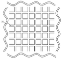
- FIG. 3 is a top view of the mesh-like conductor portion 31.
- the mesh-like conductor part 31 and the lower conductor plate 32 are arranged in a substantially parallel state, and electromagnetic waves travel through a narrow area sandwiched between the mesh-like conductor part 31 and the lower conductor plate 32.
- the power supply sheet 12 does not necessarily have the configuration illustrated in FIGS. 2 and 3.
- the power receiving unit 13 receives power from the power supply sheet 12.
- the power receiving unit 13 includes, for example, a conductor electrode unit 15 and a conductor plate 16 having a slot unit 17.
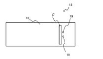
- the power receiving unit 13 is not necessarily configured as shown in FIG. FIG. 4 shows a top view of the conductor plate 16.
- non-conductor portion 14 for example, a dielectric such as resin, rubber, polymer foam, or gel material can be used.
- the conductor electrode portion 15 is a lower electrode that receives power from the power supply sheet 12.
- the conductor electrode portion 15 functions as a patch conductor.
- the length of the conductor electrode portion 15 in the longitudinal direction is set so as to resonate at the frequency of the electromagnetic wave propagating through the power supply sheet 12 when the wireless power receiving device 11 is placed on the power supply sheet 12.
- the conductor electrode part 15 is comprised by metal foil and metal plates, such as copper and aluminum, for example.
- the conductor electrode portion 15 changes its area in contact with the power supply sheet 12 when the wireless power receiving device 11 is swung in a state of being arranged so as to be in contact with the power supply sheet 12. More specifically, the non-conductor portion 14 and the conductor electrode portion 15 have a curved shape, constitute a part of the outer edge of the wireless power receiving device 11, and a central portion on the power feeding sheet 12 side. A protruding convex shape is formed.
- the conductor plate 16 is provided on the upper side of the non-conductor portion 14.
- the slot portion 17 provided in the conductor plate 16 is a portion obtained by cutting out a part of the conductor plate 16 into an elongated rectangular shape.
- the position of the slot portion 17 of the conductor plate 16 is a position and shape where impedance matching can be taken at the feeding point 19.
- the feeding point 19 can excite the slot portion 17 by applying a potential difference between the slot portion 17 and the portion on the opposite side of the feeding point 19 with the slot portion 17 as the center. You can receive power.
- the feeding points 19 are provided at two places as shown in FIG. 4, but either one may be provided.
- the slot portion 17 is provided at two positions spaced apart from each other on the left and right sides in the normal state where the wireless power receiving device 11 is placed on the power supply sheet 12.
- the conductor electrode portion 15 and the conductor plate 16 are made of, for example, a metal foil or a metal plate such as copper or aluminum.
- the power output unit 18 receives power supplied from the power receiving unit 13 and supplies power corresponding to the power to an electronic device (not shown). When the amount of power supplied from the power receiving unit 13 decreases, the power output unit 18 also decreases the amount of power supplied to the electronic device. In addition, when the amount of power supplied from the power receiving unit 13 increases, the power output unit 18 also increases the amount of power supplied to the electronic device. Since the power output unit 18 only needs to realize such input / output, the power output unit 18 may be configured simply by wiring for supplying power from the power receiving unit 13 to the electronic device, or may include a simple matching circuit. .
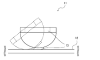
- FIG. 5 is a diagram showing a state where the wireless power receiving apparatus 11 is swung.
- a portion in this embodiment, the non-conductor portion 14 and the conductor electrode portion 15
- the wireless power receiving apparatus 11 can easily swing as shown by a dotted line in FIG.
- the distance between the power reception unit 13 and the power supply sheet 12 that is a wireless power source always changes.
- the amount of power received by the wireless power receiving apparatus 11 from the power supply sheet 12 also changes as the distance between the power reception unit 13 and the power supply sheet 12 changes.
- the wireless power receiving device 11 changes the power supply state with the swinging motion of the wireless power receiving device 11 itself, so that the output state to the electric device that is the power supply target via the power output unit 18 is also improved. Can be changed.
- the wireless power receiving device 11 is in a state in which it can easily swing, and the distance between the power receiving unit 13 and the wireless power source during the swinging motion. May change and the amount of power received may change. Therefore, the shape of the outer edge portion of the wireless power receiving apparatus 11 does not necessarily have to be smoothly curved like the non-conductor portion 14 and the conductor electrode portion 15.
- the shape of the outer edge of the wireless power receiving apparatus 11 can be easily oscillated in any convex shape such as a substantially polygonal shape as shown in FIG. 6 or a substantially elliptical shape as shown in FIG. May be provided between other structures.
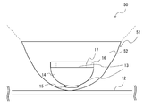
- FIG. 8 is a diagram illustrating a configuration of an illumination system 50 including the illumination device 51 and the power feeding sheet 12.
- the illumination device 51 is disposed on the power supply sheet 12.
- the illumination device 51 includes a wireless power receiving device 11 and a light emitting unit 52.
- the wireless power receiving apparatus 11 is supplied with power from the power supply sheet 12 as described above.
- the wireless power receiving apparatus 11 further supplies the supplied power to the light emitting unit 52.
- the light emitting unit 52 has a hemispherical (bowl shape) shape on the lower side (power feeding sheet 12 side), and can swing in all directions parallel to the power feeding sheet 12.
- the light emitting unit 52 can emit diffused light upward.
- the light emitting unit 52 may be constituted by a reflector formed inside the hemisphere and a point light source provided near the center thereof. Moreover, you may comprise the light emission part 52 by providing a surface light source in the whole hemispherical inner side.
- the illumination device 51 swings.
- the amount of power supplied from the power supply sheet 12 to the wireless power receiving apparatus 11 changes.
- the amount of power supplied from the wireless power receiving apparatus 11 to the light emitting unit 52 also changes, so that the illumination intensity also changes. Therefore, also in this illumination system 50, the output state of the illumination device, that is, the light emission state can be changed at low cost without using a separate dedicated device.
- FIG. 9 is a diagram illustrating a configuration of a blower system 60 including the blower 61 and the power supply sheet 12. As illustrated in FIG. 9, the blower 61 includes the wireless power receiving device 11 and the blower 62. The blower 61 is disposed on the power supply sheet 12.
- the wireless power receiving apparatus 11 is supplied with power from the power supply sheet 12 as described above.
- the wireless power receiving apparatus 11 further supplies the supplied power to the blower unit 62.
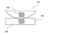
- FIG. 10 shows a configuration diagram of the wireless power receiving apparatus 101 and the induced current wireless power transmission apparatus 102 according to the second embodiment of the present invention.
- the wireless power receiving apparatus 101 includes a power receiving coil 103.
- the induced current wireless power transmission apparatus 102 includes a power transmission coil 104.
- the wireless power receiving apparatus 101 receives the power transmitted from the induction current type wireless power transmitting apparatus 102 having the power transmitting coil 104 as a wireless power source by the power receiving coil 103.
- the wireless power receiving apparatus 101 has an inductive current type wireless power transmitting apparatus 102 and a contact capable of swinging motion, and the relative positional relationship between the power receiving coil 103 and the power transmitting coil 104 changes with the swinging motion.
- the induction current type wireless power transmission apparatus 102 performs induction current type wireless power transmission using the coil 14.
- wireless power transmission can be easily performed in accordance with the change in the distance and the positional relationship between the power receiving coil 103 and the power transmitting coil 104 as in the case of wireless power transmission using a power supply sheet. The amount of power received changes.
- the wireless power receiving apparatus 101 can change the output state with respect to the electric device to which power is supplied by changing the power supply state by the swinging motion of the wireless power receiving apparatus 101 itself.
- FIG. 11 shows a configuration diagram of a wireless power receiving device 111 according to the third embodiment of the present invention and a lighting device 110 including the wireless power receiving device 111.
- the lighting device 110 includes a wireless power receiving device 111, a light emitting unit 52, and the power supply sheet 12.
- the wireless power receiving apparatus 111 has a power receiving unit 13.
- the wireless power receiving apparatus 111 is different from the wireless power receiving apparatus 11 according to the first embodiment in that it includes a plurality of power receiving units 13.
- the illumination device 110 is different from the illumination device 51 in that the plurality of light emitting units 52 are individually supplied with power from each of the plurality of power reception units 13.
- the lighting device 110 is used as an electric device to which power is supplied from the wireless power receiving device 111.
- the lighting device 110 is not necessarily a lighting device. Any configuration may be used as long as power is separately supplied to a load such as a light emitting unit or an air blowing unit which is an output unit.
- the wireless power receiving device 111 and the lighting device 110 are curved at the bottom and have a swingable contact with the power feeding sheet 12.
- each of the plurality of power receiving units 13 changes the amount of power received from the power feeding sheet 12 according to the change in the distance from the power feeding sheet 12 due to the swinging motion.
- FIG. 12 shows a state in which the illumination device 110 is swung.
- the amount of wireless power received among the plurality of power receiving units 13 during the swinging motion is changed by each power receiving unit 13. Since the plurality of light emitting units 52 are separately supplied with power from each power receiving unit 13, the intensity of light emission from each light emitting unit 52 changes based on the amount of power supplied from each power receiving unit 13.
- the wireless power receiving device 111 changes the power supply state with the swinging motion of the wireless power receiving device 111 itself with respect to the electrical device to which power is supplied, thereby changing the output state of the electronic device. Can be changed.
- the illumination device 110 changes the light emitting unit that emits the strongest light among the plurality of light emitting units 52 included in accordance with the swinging motion of the wireless power receiving device 111, so that the illumination device is more excellent in entertainment properties. Can be provided.
- a low-cost wireless power receiving device that has a function to change the output state of an electrical device such as a lighting device or a blower device, and an electrical device with excellent entertainment properties. Can be provided.
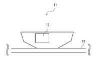
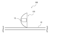
- FIG. 13 shows a configuration diagram of a wireless power receiving apparatus 131 according to the fourth embodiment of the present invention.
- the sheet feeding system 130 includes a wireless power receiving device 131 and the feeding sheet 12.
- the wireless power receiving apparatus 131 includes a power receiving unit 13.
- the wireless power receiving device 131 is a wireless power receiving device for the power feeding sheet 12 and swings while being in contact with the power feeding sheet 12, the distance between the power receiving unit 13 and the power feeding sheet 12 is
- the wireless power receiving apparatus 11 according to the first embodiment is different from the wireless power receiving apparatus 11 according to the first embodiment in that it is 1/10 or less of the wavelength of electromagnetic waves to be received.
- the wireless power receiving device 131 similarly to the wireless power receiving device 11, the wireless power receiving device 131 has a contact capable of swinging motion with the power supply sheet 12. Therefore, the wireless power receiving device 131 changes the amount of received power according to the change in the distance between the power receiving unit 13 and the power supply sheet 12 during the swing motion.
- the intensity of the electromagnetic field propagating in and on the surface of the power supply sheet 12 decreases rapidly as the distance from the surface of the power supply sheet 12 increases. Therefore, when the power receiving unit 13 is separated from the power supply sheet 12 by a certain distance or more, the power receiving unit 13 cannot receive wireless power sufficient to operate the electric device to be supplied with power.
- the distance between the power receiving unit 13 and the power supply sheet 12 is at most 1/10 or less of the wavelength of the received electromagnetic wave.
- the shape of the wireless power receiving apparatus 131 and the arrangement of the power receiving unit 13 are determined.
- the wireless power receiving apparatus 131 can always receive an amount of wireless power sufficient for the electric device to be supplied with power to operate at a minimum during the swinging motion.
- the wireless power receiving device 131 changes the output state of the electronic device by changing the power supply state with respect to the electrical device to which power is supplied, in accordance with the swinging motion of the wireless power receiving device 131 itself. be able to. Therefore, it has the function of changing the output state of an electric device such as a lighting device or a blower device that is a power supply target without using a separate dedicated device, and is always in the state of being in contact with the power supply sheet 12 and is always the minimum necessary. It is possible to provide a wireless power receiving apparatus that can supply more power than the limit.
Landscapes
- Engineering & Computer Science (AREA)
- Computer Networks & Wireless Communication (AREA)
- Power Engineering (AREA)
- Charge And Discharge Circuits For Batteries Or The Like (AREA)
- Arrangement Of Elements, Cooling, Sealing, Or The Like Of Lighting Devices (AREA)
- Non-Portable Lighting Devices Or Systems Thereof (AREA)
Description
本発明は、無線電力を受電する無線電力受電装置及び無線給電方法に関する。
近年、さまざまな無線電力供給技術が開発され、一部が実用化されるに至っている。
無線電力供給技術の例としては、例えば特許文献1のように、対向させた送電コイルと受電コイル間で発生する誘導電流を利用して、無線で電力を供給するものや、例えば、特許文献2や特許文献3のように、シート状の電磁場伝播媒体(以下、給電シートと称する)中に電力を行き渡らせ、給電シート上自由な位置に置かれた負荷に対し、無線で電力を供給する、といったものがある。
一方、たとえば照明装置において、特許文献4に示されるように、発光状態にゆらぎや特定の変化を持たせることで、リラックス効果や、エンターテインメント性を向上させることができる。
さらに、たとえば送風装置において、特許文献5に示されるように、送風状態にゆらぎや特定の変化を持たせることで、リラックス効果や、エンターテインメント性を向上させることができる。
しかし、照明装置や送風装置などの電気機器において、発光や送風などの出力状態に、ゆらぎや特定の変化を持たせるには、別途電気回路などの専用装置が必要であり、コストが増加する、という課題があった。
このような課題を受け、本発明の目的は、別途専用装置を用いず低コストで、電気機器の出力状態に変化を生じさせることができる、無線電力受電装置及び無線給電方法を提供することである。
このような課題を受け、本発明の目的は、別途専用装置を用いず低コストで、電気機器の出力状態に変化を生じさせることができる、無線電力受電装置及び無線給電方法を提供することである。
上記目的を達成するための本発明の一様態にかかる無線電力受電装置は、無線電力源から無線電力を受電する受電部と、自身もしくは自身に連結する物体に設けられた凸部形状により揺動運動可能な接点を有する揺動構造と、揺動運動によって無線電力源から前記受電部間の位置関係が変動することにより変化した無線電力量に応じた電力を電子機器に出力する電力出力部を備えたものである。
上記目的を達成するための本発明の一様態にかかる無線給電方法は、無線電力源から無線電力を受電するステップと、自身もしくは自身に連結する物体に設けられた凸部形状により揺動運動可能な接点を有する揺動構造によって無線電力源から前記受電部間の位置関係が変動することにより変化した無線電力量に応じた電力を電子機器に出力するステップを備えたものである。
本発明によれば、別途専用装置を用いず低コストで、電子機器の出力状態を変化させる機能を持った無線電力受電装置及び無線給電方法を提供することができる。
以下、図面を参照して本発明の実施の形態について説明する。但し、以下に述べる実施の形態には、本発明を実施するために技術的に好ましい限定がされているが、発明の範囲を以下に限定するものではない。
(第1の実施の形態)
本発明の第1の実施形態に係る、シート給電システム10の構成図を図1に示す。シート給電システム10は、無線電力受電装置11と、給電シート12を備える。
本発明の第1の実施形態に係る、シート給電システム10の構成図を図1に示す。シート給電システム10は、無線電力受電装置11と、給電シート12を備える。
無線電力受電装置11は、カプラ型受電装置であり、給電シート12から電磁波を受け、給電される。無線電力受電装置11は、受電部13と、非導体部14と、電力出力部18を備えている。また、本実施形態において、無線電力受電装置11は、無線電力源である給電シート12上に置かれている。ただし、無線電力受電装置11は、必ずしも給電シート12と直接に接している必要はなく、他の任意の物体と接し、給電シート12と離間した状態にあっても構わない。無線電力受電装置11は、例えば照明装置や送風装置などの電気機器の、給電インターフェイスとすることができる。
給電シート12は、無線電力受電装置11に対して給電を行う。給電シート12は、メッシュ状導体部31と、メッシュ状導体部31と間隔をおいて配置された下部導体板32と、メッシュ状導体部31の上部に設けられた第1誘電体層33と、これらメッシュ状導体部31及び下部導体板32の間の狭間領域に設けられた第2誘電体層34を有する。図2は、給電シート12の側面図であり、図3はメッシュ状導体部31の上面図である。メッシュ状導体部31よりエバネッセント波と呼ばれる電磁波が滲み出すことで、メッシュ状導体部31の上方に電磁波の浸出領域が形成される。メッシュ状導体部31と下部導体板32は、略平行な状態で配置され、メッシュ状導体部31及び下部導体板32に挟まれる狭間領域を電磁波が進行する。ただし、給電シート12は、必ずしも図2、図3に示された構成である必要はない。
受電部13は、給電シート12から電力を受電する。受電部13は、例えば、導体電極部15と、スロット部17を有する導体板16を具備する。ただし、受電部13は、必ずしも図1に示されるような構成である必要はない。
図4に、導体板16の上面図を示す。
図4に、導体板16の上面図を示す。
非導体部14としては、例えば、樹脂、ゴム、ポリマーの発泡体、ゲル材等の誘電体を用いることができる。
導体電極部15は、給電シート12から受電を行う下部電極である。導体電極部15は、パッチ導体として機能する。導体電極部15の長手方向の長さは、給電シート12に当該無線電力受電装置11を載せたときに、給電シート12を伝播する電磁波の周波数で共振するように設定される。導体電極部15は、例えば、銅やアルミニウム等の金属箔や金属板により構成される。
典型的には、導体電極部15は、無線電力受電装置11が給電シート12に接するように配置された状態で揺動した場合に、給電シート12に接する面積が変化する。より具体的には、非導体部14及び導体電極部15は、湾曲した形状を有しており、無線電力受電装置11の外縁の一部を構成しており、給電シート12側に中央部が突出した凸形を形成している。
導体板16は、非導体部14の上側に設けられる。図4に示されるように、導体板16に設けられたスロット部17は、導体板16の一部を細長の矩形状に切り欠いた部分である。導体板16のスロット部17の位置は、給電点19でインピーダンスマッチングがとれる位置および形状である。給電点19は、スロット部17を中心にスロット部17を挟んで給電点19とは反対側の部分との間に電位差を与えると、スロット部17を励振でき、また逆に上記間の電位差でもって電力を受け取ることができる。典型的には給電点19は、図4に示すように2箇所に設けられるが、どちらか一方であっても良い。本実施の形態において、スロット部17は、無線電力受電装置11を給電シート12上に載置した通常状態において、左右両側に互いに離間した位置の2か所に設けられている。
導体電極部15及び導体板16は、例えば、銅やアルミニウム等の金属箔や金属板により構成される。
電力出力部18は、受電部13から電力の供給を受けて、その電力に応じた電力を図示しない電子機器に対して供給する。電力出力部18は、受電部13から供給された電力の量が減少すれば、それに伴い、電子機器に対して供給する電力量も減少する。また、電力出力部18は、受電部13から供給された電力の量が増加すれば、それに伴い、電子機器に対して供給する電力量も増加する。電力出力部18は、このような入出力を実現できればよいため、単に受電部13から電子機器に対して電力を供給する配線によって構成されていても、さらに簡単な整合回路を含んでいてもよい。
次に、無線電力受電装置11の動作および効果について説明する。
図5は、無線電力受電装置11を揺動させた状態を示す図である。無線電力受電時、無線電力受電装置11の外縁部において凸形状を形成する部位(本実施形態においては、非導体部14及び導体電極部15)が、他の物体(本実施形態においては、給電シート12)と接している場合、無線電力受電装置11は、図7において点線で示すように、容易に揺動運動することが可能となる。そして、揺動運動中、受電部13と無線電力源である給電シート12との間の距離は、常に変化する。
このとき、無線電力受電装置11が給電シート12から受け取る電力量も、受電部13と、給電シート12の間の距離の変化に伴って変化する。
これにより無線電力受電装置11は、無線電力受電装置11自身の揺動運動に伴って電力供給状態を変動させることで、電力出力部18を介して電力の供給対象である電気機器に対する出力状態も変化させることができる。
したがって、別途専用装置を用いず、低コストに、電力供給対象である、照明装置や送風装置などの電気機器の出力状態を変化させる機能を持った、無線電力受電装置を、提供することができる。
なお、このような効果を発揮するためには、無線電力受電装置11が、容易に揺動運動が可能な状態であり、かつ揺動運動中、受電部13と無線電力源との間の距離が変化し、受電する電力量が変化すればよい。したがって、無線電力受電装置11の外縁部形状は、必ずしも非導体部14および導体電極部15のように滑らかに湾曲している必要はない。例えば、無線電力受電装置11の外縁部形状は、図6のような略多角形形状や、図7のような略楕円形のように、何らかの凸な形状において、容易に揺動運動可能な接点を、他の構造との間に有してればよい。
ここで、無線電力受電装置11に連結した他の構造が、別の他の構造との間に、揺動運動可能な接点を有する応用例について説明する。
図8は、照明装置51と給電シート12とを備えた照明システム50の構成を示す図である。照明システム50において、照明装置51は給電シート12上に配置される。照明装置51は、無線電力受電装置11と発光部52とを備えている。
無線電力受電装置11は、上述のように給電シート12から電力が供給される。無線電力受電装置11は、供給された電力を、さらに発光部52に対して供給する。
発光部52は、下側(給電シート12側)に半球状(ボウル状)の外形を有し、給電シート12と平行なあらゆる方向に対して揺動可能である。発光部52は、上方に拡散光を放射できる。発光部52は、半球状の内側に形成された反射体と、その中央近傍に設けられた点光源により構成してもよい。また、発光部52は、半球状の内側全体に面光源を設けることにより構成してもよい。
図8に示す照明システム50において、無線電力受電装置11を内蔵した照明装置51に対して風や人の力等の外力が作用すると、照明装置51が揺動する。そうすると、給電シート12から無線電力受電装置11に供給される電力量が変化する。これに伴い、無線電力受電装置11から発光部52に対して供給される電力量も変化するため、照明の照度も変化する。したがって、この照明システム50においても、別途専用装置を用いず、低コストに、照明装置の出力状態、即ち発光状態を変化させることができる。
図9は、送風装置61と給電シート12とを備えた送風システム60の構成を示す図である。図9のように、送風装置61は、無線電力受電装置11と送風部62とを備えている。送風装置61は給電シート12上に配置される。
無線電力受電装置11は、上述のように給電シート12から電力が供給される。無線電力受電装置11は、供給された電力を、さらに送風部62に対して供給する。
図9に示す送風システム60において、無線電力受電装置11を内蔵した送風装置61に対して風や人の力等の外力が作用すると、送風装置61が揺動する。そうすると、給電シート12から無線電力受電装置11に供給される電力量が変化する。これに伴い、無線電力受電装置11から送風部62に対して供給される電力量も変化するため、送風量も変化する。したがって、この照明システム50においても、別途専用装置を用いず、低コストに、送風装置の出力状態、即ち送風状態を変化させることができる。
(第2の実施形態)
本発明の第2の実施形態に係る、無線電力受電装置101及び誘導電流式無線電力送電装置102の構成図を図10に示す。無線電力受電装置101は、受電コイル103を備える。誘導電流式無線電力送電装置102は、送電コイル104を備える。
本発明の第2の実施形態に係る、無線電力受電装置101及び誘導電流式無線電力送電装置102の構成図を図10に示す。無線電力受電装置101は、受電コイル103を備える。誘導電流式無線電力送電装置102は、送電コイル104を備える。
無線電力受電装置101は、無線電力源として送電コイル104を具備した誘導電流式無線電力送電装置102からの送電を、受電コイル103により受電する。無線電力受電装置101は、誘導電流式無線電力送電装置102と、揺動運動可能な接点を持ち、揺動運動に伴い、受電コイル103と送電コイル104との相対位置関係が変化する。
次に、無線電力受電装置101の動作および効果について説明する。
誘導電流式無線電力送電装置102は、コイル14を用いた誘導電流式無線電力送電を行う。コイルによる誘導電流式無線電力送電では、給電シートを用いた無線電力送電と同様に、受電部である受電コイル103と、送電コイル104との距離、位置関係の変化に伴い、容易に無線電力送電、受電量が変化する。
これにより、無線電力受電装置101は、無線電力受電装置101自身の揺動運動により電力供給状態を変動させることで、電力の供給対象である電気機器に対して出力状態を変化させることができる。
したがって、別途専用装置を用いず、低コストに、電力供給対象である、照明装置や送風装置などの電気機器の出力状態を変化させる機能を持った、無線電力受電装置を、提供することができる。
(第3の実施形態)
本発明の第3の実施形態に係る無線電力受電装置111、及び無線電力受電装置111を備えた照明装置110の構成図を図11に示す。照明装置110は、無線電力受電装置111と、発光部52と、給電シート12を備える。
本発明の第3の実施形態に係る無線電力受電装置111、及び無線電力受電装置111を備えた照明装置110の構成図を図11に示す。照明装置110は、無線電力受電装置111と、発光部52と、給電シート12を備える。
無線電力受電装置111は、受電部13を有する。無線電力受電装置111は、受電部13を複数具備している点において、第1の実施形態に係る無線電力受電装置11と異なる。また、照明装置110は、複数ある発光部52が、それぞれ、複数ある各受電部13より個別に電力を供給される点において、照明装置51と異なる。
本実施の形態においては、無線電力受電装置111から電力を供給される電気機器として、照明装置110を用いているが、必ずしも照明装置である必要はなく、複数ある各受電部13が、複数の、出力部である発光部や送風部などの負荷に、別個に電力を供給する構成であればよい。
次に、無線電力受電装置111及び無線電力受電装置111を備えた照明装置110の動作および効果について説明する。
図11に示すように、無線電力受電装置111、及び照明装置110は、底部が湾曲しており、給電シート12との間に、揺動運動可能な接点を持つ。そして揺動運動時には、複数ある各受電部13は、揺動運動に伴う給電シート12との間の距離の変化に準じて、それぞれ給電シート12より受け取る電力量が変化する。
図12は、照明装置110を揺動させた状態を示している。例えば、図11、図12に示すように、揺動運動時には複数ある各受電部13のうち、無線電力を受電する量が各受電部13によって変化する。複数の発光部52では、各受電部13から別個に電力を供給されているため、各発光部52の発光の強弱は、各受電部13からの電力の供給量に基づいて変化する。
これにより、無線電力受電装置111は、電力の供給対象である電気機器に対して、無線電力受電装置111自身の揺動運動に伴って電力供給状態を変動させることで、電子機器の出力状態を変化させることができる。なお、照明装置110は、無線電力受電装置111の揺動運動に伴い、具備している複数の発光部52のうち、最も強く発光する発光部を変化させることで、よりエンターテインメント性に優れた照明を提供することができる。
したがって別途専用装置を用いず、低コストに、電力供給対象である照明装置や送風装置などの電気機器の出力状態を変化させる機能を持った無線電力受電装置、ならびにエンターテインメント性に優れた電気機器を提供することができる。
(第4の実施形態)
本発明の第4の実施形態に係る無線電力受電装置131の構成図を図13に示す。シート給電システム130は、無線電力受電装置131と、給電シート12を備える。
本発明の第4の実施形態に係る無線電力受電装置131の構成図を図13に示す。シート給電システム130は、無線電力受電装置131と、給電シート12を備える。
無線電力受電装置131は、受電部13を備えている。
無線電力受電装置131は、給電シート12用の無線電力受電装置である点、及び、給電シート12と接した状態で揺動運動するとき、受電部13と給電シート12との間の距離が、最大でも、受電する電磁波の波長の1/10以下である点において、第1の実施形態に係る無線電力受電装置11と異なる。
無線電力受電装置131は、給電シート12用の無線電力受電装置である点、及び、給電シート12と接した状態で揺動運動するとき、受電部13と給電シート12との間の距離が、最大でも、受電する電磁波の波長の1/10以下である点において、第1の実施形態に係る無線電力受電装置11と異なる。
次に、無線電力受電装置131の動作および効果について説明する。
図13に示すように、無線電力受電装置131は無線電力受電装置11と同様に、給電シート12との間に、揺動運動可能な接点を有する。そのため無線電力受電装置131は、揺動運動時には、受電部13と給電シート12との間の距離の変化に準じて、受電電力量が変化する。
給電シート12中及び表面を伝搬する電磁場の強度は、給電シート12表面から離れるに従い急激に減少する。そのため、受電部13が給電シート12に対して一定距離以上離れると、受電部13は、電力供給対象の電気機器を動作させるに足る無線電力を受電することができなくなる。
そこで、無線電力受電装置131が給電シート12に接した状態での揺動運動時に、受電部13と給電シート12との間の距離が、最大でも受電する電磁波の波長の1/10以下となるように、無線電力受電装置131の形状及び受電部13の配置を決定する。
これにより、無線電力受電装置131では、揺動運動中に、常に電力供給対象の電気機器が最低限動作するに足る量の無線電力を受電することができる。
無線電力受電装置131は、電力の供給対象である電気機器に対して、無線電力受電装置131自身の揺動運動に伴って、電力供給状態を変動させることで、電子機器の出力状態を変化させることができる。
したがって、別途専用装置を用いず低コストに、電力供給対象である照明装置や送風装置などの電気機器の出力状態を変化させる機能を持ち、かつ、給電シート12に接した状態で、常に必要最低限以上の電力を供給することのできる、無線電力受電装置を提供することができる。
したがって、別途専用装置を用いず低コストに、電力供給対象である照明装置や送風装置などの電気機器の出力状態を変化させる機能を持ち、かつ、給電シート12に接した状態で、常に必要最低限以上の電力を供給することのできる、無線電力受電装置を提供することができる。
以上、実施の形態を参照して本願発明を説明したが、本願発明は上記によって限定されるものではない。本願発明の構成や詳細には、発明のスコープ内で当業者が理解し得る様々な変更をすることができる。
この出願は、2012年9月27日に出願された日本出願特願2012-214051を基礎とする優先権を主張し、その開示の全てをここに取り込む。
10 シート給電システム
11 無線電力受電装置
12 給電シート
13 受電部
14 非導体部
15 導体電極部
16 導体板
17 スロット部
18 電力出力部
31 メッシュ状導体部
32 下部導体板
33 第1誘電体層
34 第2誘電体層
50 照明システム
51 照明装置
52 発光部
60 送風システム
61 送風装置
62 送風部
101 無線電力受電装置
102 誘導電流式無線電力送電装置
103 受電コイル
104 送電コイル
110 照明装置
111 無線電力受電装置
130 シート給電システム
131 無線電力受電装置
11 無線電力受電装置
12 給電シート
13 受電部
14 非導体部
15 導体電極部
16 導体板
17 スロット部
18 電力出力部
31 メッシュ状導体部
32 下部導体板
33 第1誘電体層
34 第2誘電体層
50 照明システム
51 照明装置
52 発光部
60 送風システム
61 送風装置
62 送風部
101 無線電力受電装置
102 誘導電流式無線電力送電装置
103 受電コイル
104 送電コイル
110 照明装置
111 無線電力受電装置
130 シート給電システム
131 無線電力受電装置
Claims (10)
- 無線電力源から無線電力を受電する受電手段と、
自身もしくは自身に連結する物体に設けられた凸部形状により揺動運動可能な接点を有する揺動構造と、
揺動運動によって無線電力源から前記受電手段間の位置関係が変動することにより変化した無線電力量に応じた電力を電子機器に出力する電力出力手段を備えた無線電力受電装置。 - 前記受電手段が、前記無線電力源である給電シートから無線電力を受電することを特徴とする請求項1に記載の無線電力受電装置。
- 前記給電シートに接した状態で揺動運動中、前記受電手段と前記給電シートとの間の距離が、受電する電磁波の波長の1/10以上離れないことを特徴とする請求項2に記載の無線電力受電装置。
- 前記受電手段は、少なくとも一つのスロットを有する導体板と、該導体板と間隔を空けて配置された下部電極と、該導体板及び該下部電極に連結した非導体部と、を具備し、
前記非導体部が、前記給電シートに向かって凸な形状であること、
を特徴とする請求項2又は3いずれか一項に記載の無線電力受電装置。 - 前記受電手段を複数具備することを特徴とする請求項1~4いずれか一項に記載の無線電力受電装置。
- 請求項1から5のいずれか一項に記載の無線電力受電装置と、当該無線電力受電装置から電力を供給されて発光する発光手段と、を具備することを特徴とする、照明装置。
- 請求項1から5のいずれか一項に記載の無線電力受電装置と、当該無線電力受電装置から電力を供給されて風を起こす送風手段と、を具備することを特徴とする、送風装置。
- 無線電力受電装置と給電シートを備え、
前記無線電力受電装置は、
前記給電シートから無線電力を受電する受電手段と、
自身もしくは自身に連結する物体に設けられた凸部形状により揺動運動可能な接点を有する揺動構造と、
揺動運動によって前記給電シートから前記受電手段間の位置関係が変動することにより変化した無線電力量に応じた電力を電子機器に出力する電力出力手段を備えたシート給電システム。 - 前記給電シートは、メッシュ状導体部と、該メッシュ状導体部と間隔をおいて配置された下部導体板と、該メッシュ状導体部の上層及び下層に設けられた誘電体層とを有するシート状構造であることを特徴とする、請求項8に記載のシート給電システム。
- 無線電力源から無線電力を受電するステップと、
自身もしくは自身に連結する物体に設けられた凸部形状により揺動運動可能な接点を有する揺動構造によって無線電力源から前記受電手段間の位置関係が変動することにより変化した無線電力量に応じた電力を電子機器に出力するステップを備えた無線給電方法。
Priority Applications (1)
| Application Number | Priority Date | Filing Date | Title |
|---|---|---|---|
| JP2014538087A JPWO2014049906A1 (ja) | 2012-09-27 | 2013-04-23 | 無線電力受電装置及び無線給電方法 |
Applications Claiming Priority (2)
| Application Number | Priority Date | Filing Date | Title |
|---|---|---|---|
| JP2012214051 | 2012-09-27 | ||
| JP2012-214051 | 2012-09-27 |
Publications (1)
| Publication Number | Publication Date |
|---|---|
| WO2014049906A1 true WO2014049906A1 (ja) | 2014-04-03 |
Family
ID=50387362
Family Applications (1)
| Application Number | Title | Priority Date | Filing Date |
|---|---|---|---|
| PCT/JP2013/002734 Ceased WO2014049906A1 (ja) | 2012-09-27 | 2013-04-23 | 無線電力受電装置及び無線給電方法 |
Country Status (2)
| Country | Link |
|---|---|
| JP (1) | JPWO2014049906A1 (ja) |
| WO (1) | WO2014049906A1 (ja) |
Citations (2)
| Publication number | Priority date | Publication date | Assignee | Title |
|---|---|---|---|---|
| JP2012029510A (ja) * | 2010-07-27 | 2012-02-09 | Panasonic Electric Works Co Ltd | 非接触給電式電気器具 |
| JP2012028235A (ja) * | 2010-07-27 | 2012-02-09 | Panasonic Electric Works Co Ltd | 非接触給電式電気器具 |
-
2013
- 2013-04-23 JP JP2014538087A patent/JPWO2014049906A1/ja active Pending
- 2013-04-23 WO PCT/JP2013/002734 patent/WO2014049906A1/ja not_active Ceased
Patent Citations (2)
| Publication number | Priority date | Publication date | Assignee | Title |
|---|---|---|---|---|
| JP2012029510A (ja) * | 2010-07-27 | 2012-02-09 | Panasonic Electric Works Co Ltd | 非接触給電式電気器具 |
| JP2012028235A (ja) * | 2010-07-27 | 2012-02-09 | Panasonic Electric Works Co Ltd | 非接触給電式電気器具 |
Also Published As
| Publication number | Publication date |
|---|---|
| JPWO2014049906A1 (ja) | 2016-08-22 |
Similar Documents
| Publication | Publication Date | Title |
|---|---|---|
| JP5766380B2 (ja) | 制御可能な照明アセンブリ | |
| EP3132183B1 (en) | Led lighting device and system containing antenna, and related configuring method | |
| US9859758B1 (en) | Transducer sound arrangement for pocket-forming | |
| CN105122544B (zh) | 包括天线的照明装置以及灯具 | |
| US9397395B2 (en) | Electronically steerable antenna using reconfigurable power divider based on cylindrical electromagnetic band gap (CEBG) structure | |
| US20170271748A1 (en) | Smart antenna and wireless device having the same | |
| JP6288449B2 (ja) | 車両用空調装置 | |
| US20160372979A1 (en) | Wireless power supplying apparatus | |
| JP6166633B2 (ja) | 照明用モジュール、無線通信用モジュール、照明装置、および、照明制御システム | |
| JP2010068085A (ja) | アンテナ装置 | |
| JP2014524726A (ja) | 静電容量ワイヤレス給電システムにおける効率的な電力伝送のための手法 | |
| KR101744590B1 (ko) | 수직형 전력 전송 방식의 무선 전력 전송 및 충전 장치 | |
| JP2017005429A5 (ja) | ||
| JP6731501B2 (ja) | 無線通信アンテナを有する固体照明デバイス | |
| JP2014135703A (ja) | パッチアンテナ | |
| CN106611897A (zh) | 电子装置 | |
| JPWO2015108140A1 (ja) | 携帯無線装置 | |
| CN103155354A (zh) | 表面通信设备 | |
| CN102763276A (zh) | 天线及无线通信装置 | |
| WO2020059089A1 (ja) | 送信システム、送信装置及び演出システム | |
| JP5162394B2 (ja) | アンテナ装置 | |
| US20180062269A1 (en) | Antenna apparatus | |
| WO2014049906A1 (ja) | 無線電力受電装置及び無線給電方法 | |
| TW202010217A (zh) | 無線送電裝置、無線電力傳送系統、無線送電裝置與無線受電裝置的設置方法、以及無線送電裝置與無線受電裝置的設置位置的變更方法 | |
| KR101937954B1 (ko) | 무선전력전송 조명장치 |
Legal Events
| Date | Code | Title | Description |
|---|---|---|---|
| 121 | Ep: the epo has been informed by wipo that ep was designated in this application |
Ref document number: 13841783 Country of ref document: EP Kind code of ref document: A1 |
|
| ENP | Entry into the national phase |
Ref document number: 2014538087 Country of ref document: JP Kind code of ref document: A |
|
| NENP | Non-entry into the national phase |
Ref country code: DE |
|
| 122 | Ep: pct application non-entry in european phase |
Ref document number: 13841783 Country of ref document: EP Kind code of ref document: A1 |