以下、添付図面を参照して本発明の実施例について説明する。なお、添付図面は本発明の原理に則った具体的な実施例を示しているが、これらは本発明の理解のためのものであり、決して本発明を限定的に解釈するために用いられるものではない。
Hereinafter, embodiments of the present invention will be described with reference to the accompanying drawings. The accompanying drawings show specific embodiments in accordance with the principle of the present invention, but these are for the understanding of the present invention, and are never used to interpret the present invention in a limited manner. is not.
<第1実施例>
本実施例では、マルチコアファイバ(MCF)である光ファイバと、直線アレイ型のアレイ光素子との光接続を実現する光路変換光結合デバイスの例を説明する。さらに、本実施例では、当該光ファイバとアレイ光素子と光路変換光結合デバイスとを備える光モジュールの例を説明する。
<First embodiment>
In the present embodiment, an example of an optical path conversion optical coupling device that realizes optical connection between an optical fiber that is a multi-core fiber (MCF) and a linear array type array optical element will be described. Further, in this embodiment, an example of an optical module including the optical fiber, the array optical element, and the optical path conversion optical coupling device will be described.
図1は、本発明の第1の実施例である光モジュールの例である。本実施例による光モジュール5000は、マルチコアファイバに代表される大容量光ファイバ1000(以下では、単に「光ファイバ」という)と、光モジュール5000の内部に配置された光路変換部(光路変換光結合デバイス)100と、アレイ光素子部(アレイ光素子)3000とを備える。光モジュール5000は、光ファイバ1000と接続されている。本実施例では、光ファイバ1000は、光モジュール5000の平面5001上に配置されている。また、光路変換部100は、複数の第1の斜めミラー部110-1,…,110-7を備えている。以下では、光路変換部100、光ファイバ1000、アレイ光素子部3000について、図2、3、及び4を用いて詳しく説明をする。
FIG. 1 is an example of an optical module according to the first embodiment of the present invention. The optical module 5000 according to this embodiment includes a large-capacity optical fiber 1000 represented by a multi-core fiber (hereinafter simply referred to as “optical fiber”) and an optical path conversion unit (optical path conversion optical coupling) disposed inside the optical module 5000. Device) 100 and an array optical element unit (array optical element) 3000. The optical module 5000 is connected to the optical fiber 1000. In this embodiment, the optical fiber 1000 is disposed on the plane 5001 of the optical module 5000. In addition, the optical path conversion unit 100 includes a plurality of first oblique mirror units 110-1,..., 110-7. Hereinafter, the optical path conversion unit 100, the optical fiber 1000, and the array optical element unit 3000 will be described in detail with reference to FIGS.
図2は、本発明の第1の実施例である第1の光路変換部100の例である。図1及び3では、大容量光ファイバとして、同心状に配置された7個のコア部1010-1,…,1010-7を有する光ファイバ1000を示している。光路変換部100は、この光ファイバ1000のコア部1010-1,…,1010-7に対応する構成を備える。図2に示すように、光路変換部100は、複数の(7個の)第1の斜めミラー部110-1,…,110-7と、第2の斜めミラー部115とを備える。複数の第1の斜めミラー部110-1,…,110-7は、複数のコア部1010-1,…,1010-7の位置に対応して同心状に配置されている。
FIG. 2 is an example of the first optical path conversion unit 100 according to the first embodiment of the present invention. 1 and 3 show an optical fiber 1000 having seven core portions 1010-1,..., 1010-7 arranged concentrically as a large capacity optical fiber. The optical path conversion unit 100 has a configuration corresponding to the core units 1010-1,..., 1010-7 of the optical fiber 1000. As shown in FIG. 2, the optical path conversion unit 100 includes a plurality of (seven) first oblique mirror units 110-1,..., 110-7, and a second oblique mirror unit 115. The plurality of first oblique mirror portions 110-1,..., 110-7 are concentrically arranged corresponding to the positions of the plurality of core portions 1010-1,.
光路変換部100は、光通信に用いる光の波長に対して透過性の良い材料が用いられることが好ましい。例えば、波長1.3μ~1.5μmの場合には、光路変換部100は、ガラス、樹脂、Siなどの半導体、有機材料などにより実現する。また、波長0.85μmの場合には、光路変換部100は、ガラス、樹脂、有機材料などにより実現する。
The optical path conversion unit 100 is preferably made of a material having good transparency with respect to the wavelength of light used for optical communication. For example, when the wavelength is 1.3 μm to 1.5 μm, the optical path conversion unit 100 is realized by glass, resin, a semiconductor such as Si, an organic material, or the like. When the wavelength is 0.85 μm, the optical path conversion unit 100 is realized by glass, resin, organic material, or the like.
図2では、光路変換部100の複数の第1の斜めミラー部110-1,…,110-7を、V字型の溝形状部によって作製した例である。この例では、光路変換部100において、V字型の溝形状部が、複数のコア部1010-1,…,1010-7の位置に対応して同心状に形成されている。ここでは、V字型の溝形状部を形成する2つの面のうち一方の面が反射面となる。第1の斜めミラー部110-1,…,110-7のV字型の溝形状部の反射面によって複数の光信号が反射される。また、第2の斜めミラー部115は、第1の斜めミラー部110-1,…,110-7によって反射された光信号(あるいは、第1の斜めミラー部110-1,…,110-7に向かって反射する光信号)の光路に対応する光路変換部100の面に形成されている。本実施例では、第1の斜めミラー部110-1,…,110-7が、複数の光信号を同じ高さの位置で且つ複数の光信号の光路が互いに平行になるように反射させるので、第2の斜めミラー部115は、1つの反射面として形成されている。なお、後述するように、第2の斜めミラー部115は、複数の反射面を備えるように形成されてもよい。
FIG. 2 shows an example in which a plurality of first oblique mirror portions 110-1,..., 110-7 of the optical path changing portion 100 are formed by V-shaped groove-shaped portions. In this example, in the optical path conversion unit 100, V-shaped groove-shaped portions are formed concentrically corresponding to the positions of the plurality of core portions 1010-1, ..., 1010-7. Here, one of the two surfaces forming the V-shaped groove-shaped portion is a reflective surface. A plurality of optical signals are reflected by the reflecting surfaces of the V-shaped groove-shaped portions of the first oblique mirror portions 110-1,..., 110-7. In addition, the second oblique mirror unit 115 is configured such that the optical signals reflected by the first oblique mirror units 110-1, ..., 110-7 (or the first oblique mirror parts 110-1, ..., 110-7). Is formed on the surface of the optical path conversion unit 100 corresponding to the optical path of the optical signal reflected toward the. In the present embodiment, the first oblique mirror sections 110-1,..., 110-7 reflect the plurality of optical signals at the same height position so that the optical paths of the plurality of optical signals are parallel to each other. The second oblique mirror part 115 is formed as one reflecting surface. As will be described later, the second oblique mirror portion 115 may be formed to have a plurality of reflecting surfaces.
図3は、本発明の第1の実施例である大容量光ファイバ1000の例である。光ファイバ1000は、同心状に配置された複数のコア部1010-1,…,1010-7を備えている。この図では、複数のコア部1010-1,…,1010-7が縦方向に延びている。この図では、コア数が7の場合の例を示しているが、後述するように、コア数を19個にしてもよい。各コア部1010-1,…,1010-7の位置関係について、詳細には図6を用いて後述する。
FIG. 3 shows an example of a large-capacity optical fiber 1000 according to the first embodiment of the present invention. The optical fiber 1000 includes a plurality of core portions 1010-1,..., 1010-7 arranged concentrically. In this figure, a plurality of core portions 1010-1,..., 1010-7 extend in the vertical direction. This figure shows an example in which the number of cores is 7, but the number of cores may be 19 as will be described later. The positional relationship between the core portions 1010-1,..., 1010-7 will be described later in detail with reference to FIG.
図4は、本発明の第1の実施例であるアレイ光素子部3000の例である。アレイ光素子部3000は、受光素子あるいは発光素子のどちらの場合でも本発明に適応することが可能である。本発明のアレイ光素子部3000は、複数の光信号が入射する、あるいは複数の光信号を出射する複数の素子(入射部あるいは出射部)3010-1,…,3010-7を備える。複数の素子3010-1,…,3010-7は、おおよそ直線状に配置されている。ここでは、アレイ光素子部3000は、汎用的な直線アレイ型の光デバイスである。
FIG. 4 shows an example of the array optical element unit 3000 according to the first embodiment of the present invention. The array optical element unit 3000 can be applied to the present invention in either case of a light receiving element or a light emitting element. The array optical element unit 3000 of the present invention includes a plurality of elements (incident part or emitting part) 3010-1,. The plurality of elements 3010-1,..., 3010-7 are arranged approximately linearly. Here, the array optical element unit 3000 is a general-purpose linear array type optical device.
上述したように、アレイ光素子部3000は、受光素子あるいは発光素子のどちらでも構わない。例えば、アレイ光素子部3000が受光素子の場合、複数のコア部1010-1,…,1010-7から出射される複数の光信号が光路変換部100によって光路が変換されて、光路変換部100からの複数の光信号をアレイ光素子部3000によって受けることになる。一方、アレイ光素子部3000が発光素子の場合、複数の光信号がアレイ光素子部3000から光路変換部100へ入射し、それら複数の光信号が光路変換部100によって光路が変換されて、光路変換部100からの光信号が複数のコア部1010-1,…,1010-7に入射することになる。
As described above, the array optical element unit 3000 may be either a light receiving element or a light emitting element. For example, when the array optical element unit 3000 is a light receiving element, a plurality of optical signals emitted from the plurality of core units 1010-1,..., 1010-7 are converted in optical path by the optical path conversion unit 100, and the optical path conversion unit 100 Are received by the array optical element unit 3000. On the other hand, when the array optical element unit 3000 is a light emitting element, a plurality of optical signals are incident on the optical path conversion unit 100 from the array optical element unit 3000, and the optical path is converted by the optical path conversion unit 100 to obtain an optical path. The optical signal from the conversion unit 100 enters the plurality of core units 1010-1,..., 1010-7.
図5は、本発明の第1の実施例である光路変換部100の別の例である。図2の例では、光路変換部100の複数の第1の斜めミラー部110-1,…,110-7を、V字型の溝形状部によって作製した例を示した。図5では、複数の第1の斜めミラー部110-1,…,110-7を、切り欠き部によって作製する例を示している。図5では、光路変換部100に複数の切り欠き部111-1,…,111-3を作製し、これらの切り欠き部111-1,…,111-3によって出来た面のそれぞれを複数の第1の斜めミラー部110-1,…,110-7とする。切り欠き部111-1,…,111-3は、複数の第1の斜めミラー部110-1,…,110-7が複数のコア部1010-1,…,1010-7の位置に対応して同心状に配置されるように、形成される。
FIG. 5 shows another example of the optical path changing unit 100 according to the first embodiment of the present invention. In the example of FIG. 2, the example in which the plurality of first oblique mirror portions 110-1,..., 110-7 of the optical path changing portion 100 are formed by V-shaped groove-shaped portions is shown. FIG. 5 shows an example in which a plurality of first oblique mirror portions 110-1,..., 110-7 are manufactured by notches. In FIG. 5, a plurality of notches 111-1,..., 111-3 are formed in the optical path conversion unit 100, and each of the surfaces formed by these notches 111-1,. The first oblique mirror units 110-1,..., 110-7 are assumed. In the cutout portions 111-1,..., 111-3, the plurality of first oblique mirror portions 110-1,..., 110-7 correspond to the positions of the plurality of core portions 1010-1,. So that they are arranged concentrically.
このように、光信号の光路変換には、第1の斜めミラー部110-1,…,110-7と複数のコア部1010-1,…,1010-7との間の相対的な位置関係が重要である。複数の第1の斜めミラー部110-1,…,110-7は、複数のコア部1010-1,…,1010-7の位置に対応して同心状に配置された反射面を少なくとも有していればよい。したがって、光信号が第1の斜めミラー部110-1,…,110-7において実際に反射する個所(反射面)以外の光路変換部100の形状については、任意に作製する事が可能である。なお、光路変換部100の材料として、樹脂あるいは低融点のガラスなどを用いた場合、金型によって製造が可能である。したがって、図2のようなV字型の溝形状部や図5のような切り欠き部が形成された金型を用いることによって、光路変換部100の製造が容易になる。
As described above, the relative positional relationship between the first oblique mirror portions 110-1,..., 110-7 and the plurality of core portions 1010-1,. is important. The plurality of first oblique mirror portions 110-1,..., 110-7 have at least reflecting surfaces arranged concentrically corresponding to the positions of the plurality of core portions 1010-1,. It only has to be. Therefore, the shape of the optical path conversion unit 100 other than the part (reflection surface) where the optical signal is actually reflected by the first oblique mirror units 110-1,..., 110-7 can be arbitrarily formed. . In addition, when resin, low melting glass, etc. are used as a material of the optical path conversion part 100, it can manufacture with a metal mold | die. Therefore, by using a mold having a V-shaped groove shape portion as shown in FIG. 2 and a notch portion as shown in FIG. 5, the optical path conversion portion 100 can be easily manufactured.
また、図5の例においても、第2の斜めミラー部115は、第1の斜めミラー部110-1,…,110-7によって反射された光信号(あるいは、第1の斜めミラー部110-1,…,110-7に向かって反射する光信号)の光路に対応する光路変換部100の面に形成されている。光路変換部100における複数の第1の斜めミラー部110-1,…,110-7と斜めミラー部115は、反射率を上げる方が効率良く好ましいため、第1及び第2の斜めミラー部110-1,…,110-7及び115に金属(アルミニウム、金など)、あるいは誘電体多層膜によるコーティングなどを行ってもよい。なお、図2の光路変換部100と図5の光路変換部100において、光信号の光路は同じである。したがって、以下では、斜視図及び断面図等がシンプルになる図5の光路変換部100を用いて説明を行う。
In the example of FIG. 5 as well, the second oblique mirror unit 115 includes the optical signals reflected by the first oblique mirror units 110-1,..., 110-7 (or the first oblique mirror unit 110- 1,..., 110-7 are formed on the surface of the optical path conversion unit 100 corresponding to the optical path of the optical signal. Since the plurality of first oblique mirror portions 110-1,..., 110-7 and the oblique mirror portion 115 in the optical path changing portion 100 are preferably more efficient in increasing the reflectivity, the first and second oblique mirror portions 110 are used. -1,..., 110-7 and 115 may be coated with a metal (aluminum, gold, etc.) or a dielectric multilayer film. 2 and the optical path conversion unit 100 in FIG. 5 have the same optical path. Therefore, the following description will be made using the optical path conversion unit 100 of FIG. 5 in which the perspective view and the cross-sectional view are simplified.
図6は、本発明の第1の実施例である光モジュール5000の上面図である。マルチコアファイバである光ファイバ1000において、幾何学的に隣接する各コア部1010-1,…,1010-7間の間隔を均一にして、光信号を各コア部1010-1,…,1010-7で伝送する際の光クロストークを等しく抑制することが好ましい。この条件を満たすには、例えば、7個のコア部1010-1,…,1010-7がある場合、コア部1010-1,…,1010-6を正六角形に配置し、その正六角形の中心にコア部1010-7を配置する方法がある。例えば、隣接する3個のコア部1010-2,1010-3,1010-7が形成する三角形は正三角形になるので、図6におけるθmは60°となる。
FIG. 6 is a top view of the optical module 5000 according to the first embodiment of the present invention. In the optical fiber 1000 that is a multi-core fiber, an optical signal is sent to each of the core portions 1010-1,..., 1010-7 by making the intervals between the geometrically adjacent core portions 1010-1,. It is preferable to suppress optical crosstalk at the same time during transmission. To satisfy this condition, for example, when there are seven core portions 1010-1,..., 1010-7, the core portions 1010-1,..., 1010-6 are arranged in a regular hexagon, and the center of the regular hexagon There is a method of arranging the core portion 1010-7. For example, the triangle formed by the three adjacent core portions 1010-2, 1010-3, and 1010-7 is an equilateral triangle, and θm in FIG. 6 is 60 °.
光路変換を実現する方法を、以下詳細に説明する。ここでは、アレイ光素子部3000が受光素子の場合を例として説明する。この例では、複数のコア部1010-1,…,1010-7から出射される複数の光信号が光路変換部100によって光路が変換されて、光路変換部100からの複数の光信号をアレイ光素子部3000の各素子3010-1,…,3010-7によって受けることになる。光ファイバ1000を上面から見て、アレイ光素子部3000に光信号を引き出すには、他のコア部を避け、直線状に斜めに引き出すやり方が考え易い。この斜めに引き出す角度θsは、7コアの場合では約20°となる。ここでは、複数の光信号の光路が互いに平行になるように複数の光信号を反射させるために角度θsを約20°としているが、光クロストークを抑制する点においては、複数の光信号の光路が互いに交差しないようになっていればよい。したがって、斜めに引き出す角度θsは、約20°に限定されず、複数の光信号の光路が互いに交差しないような角度の範囲で設定することができる。
The method for realizing the optical path conversion will be described in detail below. Here, the case where the array optical element unit 3000 is a light receiving element will be described as an example. In this example, the optical paths of the plurality of optical signals emitted from the plurality of core units 1010-1,..., 1010-7 are converted by the optical path conversion unit 100, and the plurality of optical signals from the optical path conversion unit 100 are converted into array light. It is received by each element 3010-1,..., 3010-7 of the element unit 3000. In order to draw an optical signal to the array optical element unit 3000 when the optical fiber 1000 is viewed from the top, it is easy to consider a method of pulling out the other cores and obliquely in a straight line. The angle θs drawn obliquely is about 20 ° in the case of 7 cores. Here, the angle θs is set to about 20 ° in order to reflect the plurality of optical signals so that the optical paths of the plurality of optical signals are parallel to each other. However, in terms of suppressing optical crosstalk, It is only necessary that the optical paths do not cross each other. Accordingly, the angle θs drawn obliquely is not limited to about 20 °, and can be set within an angle range in which the optical paths of the plurality of optical signals do not intersect each other.
図7Aは、本発明の第1の実施例である光路変換部とアレイ光素子部を示す側面図である。また、図7Bは、本発明の第1の実施例である光路変換部とアレイ光素子部を示す上面図である。図7Bの上面図において、第1の斜めミラー部110-1,…,110-7は、長方形で簡略的に示されている。
FIG. 7A is a side view showing an optical path conversion unit and an array optical element unit according to the first embodiment of the present invention. FIG. 7B is a top view showing the optical path conversion unit and the array optical element unit according to the first embodiment of the present invention. In the top view of FIG. 7B, the first oblique mirror portions 110-1,..., 110-7 are simply shown as rectangles.
図7Aに示すように、光ファイバ1000の複数のコア部1010-1,…,1010-7から出射した光信号は、光路変換部100の上面に配置された複数の第1のレンズ部120-1,…,120-7で集光される。集光された各光信号は、光路変換部100の第1の斜めミラー部110-1,…,110-7で反射され、側面から見て、略同じ高さになるように直角に反射される。
As shown in FIG. 7A, the optical signals emitted from the plurality of core portions 1010-1,..., 1010-7 of the optical fiber 1000 are sent to the plurality of first lens portions 120- arranged on the upper surface of the optical path changing portion 100. 1,..., 120-7. Each of the collected optical signals is reflected by the first oblique mirror units 110-1,..., 110-7 of the optical path conversion unit 100, and is reflected at a right angle so as to have substantially the same height when viewed from the side. The
このような光路変換は、図7Bで示すように、第1の斜めミラー部110-1,…,110-7を、光ファイバ1000の各コア部1010-1,…,1010-7の、およそ真下に配置することで実現できる。すなわち、上述したように、複数の第1の斜めミラー部110-1,…,110-7の反射面は、複数のコア部1010-1,…,1010-7の位置に対応して同心状に配置されている。第1の斜めミラー部110-1,…,110-7は、複数のコア部1010-1,…,1010-7から出射される複数の光信号を、当該複数の光信号の光路150-1,…,150-7が互いに交差しないように反射させる。本実施例では、第1の斜めミラー部110-1,…,110-7は、複数の光信号を、側面から見て同じ高さで、且つ上面から見て斜めに概平行に反射させる。このように引き出された複数の光信号は、第2の斜めミラー部115によって、下方に、且つ、複数の光信号の光路が互いに略平行になるように反射される。この例では、複数の光信号は、第2の斜めミラー部115によって、略真下に直角に光路変換される。そして、第2のレンズ部130-1,…,130-7で集光された光信号は、アレイ光素子部3000の各々の素子3010-1,…,3010-7(この場合は、入射部)に入射する。なお、アレイ光素子部3000が発光素子の場合も、上述した光路を逆に辿って実現される。以上の構成によって、光ファイバ1000とアレイ光素子部3000との光結合を行うための光路変換部100を提供することが可能となる。
As shown in FIG. 7B, such optical path conversion is performed by connecting the first oblique mirror portions 110-1,..., 110-7 to the core portions 1010-1,. This can be achieved by placing it directly below. That is, as described above, the reflective surfaces of the plurality of first oblique mirror portions 110-1,..., 110-7 are concentric corresponding to the positions of the plurality of core portions 1010-1,. Is arranged. The first oblique mirror units 110-1,..., 110-7 receive the plurality of optical signals emitted from the plurality of core units 1010-1,..., 1010-7, and the optical paths 150-1 of the plurality of optical signals. ,..., 150-7 are reflected so as not to cross each other. In this embodiment, the first oblique mirror sections 110-1,..., 110-7 reflect a plurality of optical signals at the same height when viewed from the side surface and obliquely and substantially parallel when viewed from the upper surface. The plurality of optical signals drawn out in this way are reflected downward by the second oblique mirror unit 115 so that the optical paths of the plurality of optical signals are substantially parallel to each other. In this example, a plurality of optical signals are optically path-converted by a second oblique mirror unit 115 at a right angle substantially below. The optical signals collected by the second lens units 130-1,..., 130-7 are converted into the elements 3010-1,..., 3010-7 (in this case, the incident unit) of the array optical element unit 3000. ). In addition, when the array optical element unit 3000 is a light-emitting element, the above-described optical path is traced in reverse. With the above configuration, it is possible to provide the optical path conversion unit 100 for performing optical coupling between the optical fiber 1000 and the array optical element unit 3000.
なお、本実施例では、第1の斜めミラー部110-1,…,110-7が、複数の光信号を、側面から見て同じ高さで略直角に、且つ上面から見て複数の光信号の光路150-1,…,150-7が互いに概平行になるように反射させるが、このような構成に限定されない。第1の斜めミラー部110-1,…,110-7による反射の位置(高さ)は異なってもよいし、複数の光信号の光路が少なくとも互いに交差しなければよい。最終的に、第2の斜めミラー部115によって反射された光信号が、アレイ光素子部3000の各々の素子3010-1,…,3010-7に入射すればよく、第1の斜めミラー部110-1,…,110-7の反射の位置(高さ)や反射方向に合わせて、第2の斜めミラー部115を高さや角度が異なる複数の反射面で構成すればよい。なお、本実施例では、複数の光信号を、側面から見て同じ高さで、且つ複数の光信号の光路が互いに概平行になるように反射させているので、第2の斜めミラー部115を1つの反射面として形成できるという利点がある。
In this embodiment, the first oblique mirror sections 110-1,..., 110-7 receive a plurality of optical signals at a substantially right angle at the same height when viewed from the side and a plurality of light when viewed from the top. The signal optical paths 150-1,..., 150-7 are reflected so as to be substantially parallel to each other, but the present invention is not limited to such a configuration. The positions (heights) of reflection by the first oblique mirror sections 110-1,..., 110-7 may be different, and the optical paths of the plurality of optical signals may be at least not intersecting each other. Finally, the optical signal reflected by the second oblique mirror unit 115 may be incident on each of the elements 3010-1,..., 3010-7 of the array optical element unit 3000, and the first oblique mirror unit 110. The second oblique mirror unit 115 may be configured by a plurality of reflecting surfaces having different heights and angles in accordance with the reflection position (height) and the reflection direction of −1,. In this embodiment, since the plurality of optical signals are reflected at the same height when viewed from the side and the optical paths of the plurality of optical signals are substantially parallel to each other, the second oblique mirror unit 115 is reflected. Can be formed as one reflecting surface.
本実施例によれば、汎用的なコア数(7コア、19コアなど)のMCF(光ファイバ1000)と汎用的な光デバイス(例えば、直線アレイ型のアレイ光素子部3000)との光接続に関してカスタムレイアウトが必要ない光路変換部100(光路変換光結合デバイス)を提供することができる。これにより、MCFと、汎用的な直線アレイ型の光デバイスとの光接続を低損失で、小型で、簡易に実現することができる。
According to this embodiment, optical connection between a general-purpose number of cores (7 cores, 19 cores, etc.) MCF (optical fiber 1000) and a general-purpose optical device (for example, a linear array type array optical element unit 3000). Therefore, it is possible to provide an optical path conversion unit 100 (optical path conversion optical coupling device) that does not require a custom layout. As a result, the optical connection between the MCF and a general-purpose linear array optical device can be easily realized with a low loss, a small size, and the like.
特に、特許文献1等の従来技術では、同心状にコアが配置された汎用的なMCFを使用しておらず、光ファイバ自体も光路変換デバイスの上に傾斜して配置したりなど、カスタムレイアウトが必要になる。したがって、特許文献1の技術では、光モジュールも大型でコストのかかる構造となる。
In particular, the conventional technology such as Patent Document 1 does not use a general-purpose MCF in which cores are concentrically arranged, and the optical fiber itself is inclined on the optical path conversion device. Is required. Therefore, in the technique of Patent Document 1, the optical module also has a large and costly structure.
また、特許文献1では、光ファイバ自体も光路変換デバイスの上に傾斜して配置する関係上、光ファイバの調芯なども難しくなる。一方、本実施例によれば、図1に示すように、光ファイバ1000は、光モジュール5000の平面5001上に置く構成となっている。光ファイバ1000を平面5001上に置いた状態で光ファイバの調芯が可能となるので、従来に比べて光ファイバの調芯も容易になるという利点もある。
In Patent Document 1, it is difficult to align the optical fiber because the optical fiber itself is inclined and disposed on the optical path conversion device. On the other hand, according to the present embodiment, as shown in FIG. 1, the optical fiber 1000 is placed on the plane 5001 of the optical module 5000. Since the optical fiber can be aligned while the optical fiber 1000 is placed on the flat surface 5001, there is an advantage that the alignment of the optical fiber is easier than in the prior art.
<第2実施例>
本実施例では、アレイ光素子部3000の各素子(入射部あるいは出射部)3010-1,…,3010-7のピッチ間隔が光ファイバ1000のコア部1010-1,…,1010-7から斜めに引き出した光線の間隔よりも広い場合に、光信号の光路のピッチ間隔を広げる実施例を示している。以下では、本実施例を図8A~図10を用いて説明する。ここでは、アレイ光素子部3000が受光素子の場合を例として説明する。
<Second embodiment>
In this embodiment, the pitch interval of each element (incident part or outgoing part) 3010-1,..., 3010-7 of the array optical element part 3000 is oblique from the core parts 1010-1,. In this example, the pitch interval of the optical path of the optical signal is widened when the interval between the light beams drawn out is wider. Hereinafter, this embodiment will be described with reference to FIGS. 8A to 10. Here, the case where the array optical element unit 3000 is a light receiving element will be described as an example.
図8Aは、第2実施例に係る光路変換部とアレイ光素子部の側面図である。また、図8Bは、第2実施例に係る光路変換部とアレイ光素子部の上面図である。なお、図8Bの上面図において、第1の斜めミラー部110-1,…,110-7は、長方形で簡略的に示されている。
FIG. 8A is a side view of the optical path conversion unit and the array optical element unit according to the second embodiment. FIG. 8B is a top view of the optical path conversion unit and the array optical element unit according to the second embodiment. In the top view of FIG. 8B, the first oblique mirror portions 110-1,..., 110-7 are simply shown as rectangles.
図8Bでは、アレイ光素子部3000の各素子(ここでは、入射部)3010-1,…,3010-7のピッチ間隔が光ファイバ1000のコア部1010-1,…,1010-7から斜めに引き出した光信号の光路150-1,…,150-7の間隔よりも広くなっている。この場合、図8Aに示すように、光路変換部100は、第2の光路変換部200を備える。第2の光路変換部200は、第2の斜めミラー部115で反射された複数の光信号の光路間隔を変更して、複数の光信号をアレイ光素子部3000の各々の素子3010-1,…,3010-7に入射させる。
In FIG. 8B, the pitch interval of each element (here, the incident part) 3010-1,..., 3010-7 of the array optical element part 3000 is obliquely inclined from the core parts 1010-1,. It is wider than the interval between the optical paths 150-1,. In this case, as illustrated in FIG. 8A, the optical path conversion unit 100 includes a second optical path conversion unit 200. The second optical path conversion unit 200 changes the optical path interval of the plurality of optical signals reflected by the second oblique mirror unit 115, and converts the plurality of optical signals into each element 3010-1, ..., 3010-7.
光ファイバ1000の複数のコア部1010-1,…,1010-7から出射した光信号は、光路変換部100の上面に配置された複数の第1のレンズ部120-1,…,120-7で集光され、その後、第1の斜めミラー部110-1,…,110-7で反射され、さらに、第2の斜めミラー部115で下方に反射されることは、第1実施例と同様であるため、説明を省略する。第2の光路変換部200によって光信号の光路のピッチ間隔を変更する構成を図9を用いて説明する。
The optical signals emitted from the plurality of core portions 1010-1,..., 1010-7 of the optical fiber 1000 are a plurality of first lens portions 120-1,. , 110-7, and then reflected by the first oblique mirror unit 110-1,..., 110-7, and further reflected downward by the second oblique mirror unit 115, as in the first embodiment. Therefore, the description is omitted. A configuration in which the second optical path conversion unit 200 changes the pitch interval of the optical path of the optical signal will be described with reference to FIG.
図9は、第2の光路変換部を示す断面図である。第2の光路変換部200は、凹レンズ部200-1と、凸レンズ部200-3と、レンズ部230とを備える。凹レンズ部200-1と凸レンズ部200-3とは、枠体200aによって支持されている。ここで、凸レンズ部200-3の焦点の位置と凹レンズ部200-1の焦点の位置を同じにする(焦点300)。また、集光レンズ部230は、複数のレンズ部230-1,…,230-7を備える。
FIG. 9 is a cross-sectional view showing the second optical path conversion unit. The second optical path conversion unit 200 includes a concave lens unit 200-1, a convex lens unit 200-3, and a lens unit 230. The concave lens part 200-1 and the convex lens part 200-3 are supported by a frame body 200a. Here, the focal position of the convex lens portion 200-3 and the focal position of the concave lens portion 200-1 are made the same (focal point 300). In addition, the condensing lens unit 230 includes a plurality of lens units 230-1, ..., 230-7.
光路変換部100の第2の斜めミラー部115によって略平行かつ真下に降りてきた光信号は、凹レンズ部200-1によって広がるように進む。次に、凸レンズ部200-3によって、これらの光信号は狭められるが、凸レンズ部200-3の焦点の位置と凹レンズ部200-1の焦点の位置が同じになっている(焦点300)ので、出射した光信号は、略平行かつ真下に進む。
The optical signal that has fallen substantially parallel and directly below by the second oblique mirror unit 115 of the optical path conversion unit 100 travels so as to spread by the concave lens unit 200-1. Next, these optical signals are narrowed by the convex lens unit 200-3, but the focal position of the convex lens unit 200-3 and the focal position of the concave lens unit 200-1 are the same (focal point 300). The emitted optical signal travels substantially parallel and directly below.
その後、凸レンズ部200-3を通過した光信号をレンズ部230-1,…,230-7によって絞り、アレイ光素子部3000の各素子3010-1,…,3010-7に入射させる。なお、アレイ光素子部3000が発光素子の場合も、上述した光路を逆に辿って実現される。また、この図の奥行き方向に対しては、ビームを広げる必要は無いため、凹レンズ部200-1及び凸レンズ部200-3は、シリンドリカルレンズを用いてもよい。
Thereafter, the optical signal that has passed through the convex lens part 200-3 is stopped by the lens parts 230-1,..., 230-7, and is incident on the elements 3010-1,..., 3010-7 of the array optical element part 3000. In addition, when the array optical element unit 3000 is a light-emitting element, the above-described optical path is traced in reverse. In addition, since there is no need to expand the beam in the depth direction in this figure, the concave lens unit 200-1 and the convex lens unit 200-3 may use cylindrical lenses.
図10は、本発明の第2の実施例である第2の光路変換部の別の例の断面図である。この例の第2の光路変換部210は、多角形の形状をした第1のプリズム部210-1と、多角形の形状をした第2のプリズム部220-3とを備える。この例では、第1のプリズム部210-1が、複数の光信号の光路間隔を広げて、第2のプリズム部220-3が、複数の光信号の光路を互いに略平行にする。すなわち、図10に示すように、光路変換部100の第2の斜めミラー部115によって略平行かつ真下に降りてきた光信号は、第1のプリズム部210-1よって広がるように進む。次に、光信号は、第2のプリズム部220-3によって略平行かつ真下に進む。この例では、凹レンズ部200-1及び凸レンズ部200-3の代わりに、第1のプリズム部210-1及び第2のプリズム部220-3を用いることによって、光信号のビーム自体がレンズによって広がったり、狭まったりする影響を無くすことが可能となる。
FIG. 10 is a cross-sectional view of another example of the second optical path changing unit according to the second embodiment of the present invention. The second optical path conversion unit 210 in this example includes a first prism unit 210-1 having a polygonal shape and a second prism unit 220-3 having a polygonal shape. In this example, the first prism unit 210-1 widens the optical path intervals of the plurality of optical signals, and the second prism unit 220-3 makes the optical paths of the plurality of optical signals substantially parallel to each other. That is, as shown in FIG. 10, the optical signal that has fallen substantially parallel and directly below by the second oblique mirror unit 115 of the optical path conversion unit 100 travels so as to spread by the first prism unit 210-1. Next, the optical signal travels substantially parallel and directly below by the second prism portion 220-3. In this example, by using the first prism unit 210-1 and the second prism unit 220-3 instead of the concave lens unit 200-1 and the convex lens unit 200-3, the beam of the optical signal itself is spread by the lens. It becomes possible to eliminate the influence of narrowing or narrowing.
なお、光信号の光路を広げた後に略平行に進ませる構成であればよく、回折格子やミラーなどの別の部材で第2の光路変換部200を構成してもよい。また、上述の実施例では枠体200aによって凹レンズ部200-1と凸レンズ部200-3を支持されているが、このように枠体200aを用いずに、光路変換部100の一部を切り欠く形で、一体的に第2の光路変換部200、210などを形成することも可能である。
Note that the second optical path conversion unit 200 may be configured with another member such as a diffraction grating or a mirror as long as the optical path of the optical signal is widened and then traveled approximately in parallel. In the above-described embodiment, the concave lens portion 200-1 and the convex lens portion 200-3 are supported by the frame body 200a. However, a part of the optical path conversion unit 100 is cut out without using the frame body 200a. It is also possible to integrally form the second optical path conversion units 200, 210 and the like.
本実施例では、アレイ光素子部3000の各素子(入射部あるいは出射部)3010-1,…,3010-7のピッチ間隔が光ファイバ1000のコア部1010-1,…,1010-7から斜めに引き出した光信号の光路150-1,…,150-7の間隔よりも広い場合においても、光ファイバ1000とアレイ光素子部3000との光結合が可能になる。また、本実施例では、複数の第1の斜めミラー部110-1,…,110-7の反射面の角度の設定が同一であり、第2の斜めミラー部115も1つの反射面として構成できるので、第1の斜めミラー部110-1,…,110-7及び第2の斜めミラー部115の構成が簡易になるという利点がある。
In this embodiment, the pitch interval of each element (incident part or outgoing part) 3010-1,..., 3010-7 of the array optical element part 3000 is oblique from the core parts 1010-1,. Even when the distance between the optical paths 150-1,..., 150-7 of the optical signal drawn out to the optical signal is wider, the optical fiber 1000 and the array optical element unit 3000 can be optically coupled. In this embodiment, the angles of the reflection surfaces of the plurality of first oblique mirror portions 110-1,..., 110-7 are the same, and the second oblique mirror portion 115 is also configured as one reflection surface. Therefore, there is an advantage that the configuration of the first oblique mirror unit 110-1,..., 110-7 and the second oblique mirror unit 115 is simplified.
<第3実施例>
図11は、本発明の第3の実施例であり、コア数が19の場合の大容量光ファイバ1000に適用する光モジュールの上面図である。
<Third embodiment>
FIG. 11 is a top view of an optical module that is a third embodiment of the present invention and that is applied to a large-capacity optical fiber 1000 when the number of cores is 19.
マルチコアファイバでは、前述した通り、幾何学的に隣接する各コア部1020-1,…,1020-19間の間隔を均一にして、光信号を各コア部1020-1,…,1020-19で伝送する際の光クロストークを等しく抑制することが好ましい。この条件を満たすには、例えば、19個のコア部1020-1,…,1020-19がある場合、6個のコア部を正六角形に配置し、その正六角形の辺の長さに等しい正十二角形上に12個のコア部を配置し、正六角形と正十二角形の中心が同じ位置になるように、コア部1020-19を配置する。さらに、コア部1020-19とコア部1020-13の距離、コア部1020-13とコア部1020-1の距離が、正六角形(正十二角形上)の辺の長さに等しくなるように配置する。隣接する3個のコア部が形成する三角形は正三角形になるので、図11におけるθmは60°となる。
In the multi-core fiber, as described above, the spacing between the geometrically adjacent core portions 1020-1,..., 1020-19 is made uniform, and the optical signal is transmitted through the core portions 1020-1,. It is preferable to equally suppress optical crosstalk during transmission. To satisfy this condition, for example, when there are 19 core portions 1020-1,..., 1020-19, 6 core portions are arranged in a regular hexagon, and a regular length equal to the length of the side of the regular hexagon. Twelve core parts are arranged on the dodecagon, and the core parts 1020-19 are arranged so that the centers of the regular hexagon and the regular dodecagon are at the same position. Further, the distance between the core part 1020-19 and the core part 1020-13 and the distance between the core part 1020-13 and the core part 1020-1 are equal to the length of the side of the regular hexagon (on the regular dodecagon). Deploy. Since the triangle formed by the three adjacent core portions is a regular triangle, θm in FIG. 11 is 60 °.
図6で示した7コアの場合と同様に、大容量光ファイバ1000を上面から見て、アレイ光素子部3000に光信号を引き出すには、他のコア部を避け、直線状に斜めに引き出すやり方が考え易い。この斜めに引き出す角度θsは、19コアの場合では約12°となる。
As in the case of the seven cores shown in FIG. 6, in order to draw out an optical signal to the array optical element unit 3000 when the large-capacity optical fiber 1000 is viewed from the top surface, the other core portions are avoided and the linear optical signal is drawn obliquely. Easy to think about how to do it. The angle θs drawn obliquely is about 12 ° in the case of 19 cores.
本実施例では、19個の第1の斜めミラー部が、19個のコア部1020-1,…,1020-19の位置に対応して同心状に配置される。ここでは、19個の第1の斜めミラー部が、複数の光信号を複数の光信号の光路が互いに略平行になるように反射させるために、角度θsを約12°としているが、光クロストークを抑制する点においては、複数の光信号の光路が互いに交差しないようになっていればよい。したがって、斜めに引き出す角度θsは、約12°に限定されず、複数の光信号の光路が互いに交差しないような角度の範囲で設定することができる。
In the present embodiment, the 19 first oblique mirror portions are arranged concentrically corresponding to the positions of the 19 core portions 1020-1,..., 1020-19. Here, the nineteen first oblique mirror portions reflect the plurality of optical signals so that the optical paths of the plurality of optical signals are substantially parallel to each other, but the angle θs is about 12 °. In terms of suppressing talk, it is only necessary that the optical paths of a plurality of optical signals do not cross each other. Therefore, the angle θs drawn obliquely is not limited to about 12 °, and can be set within an angle range such that the optical paths of a plurality of optical signals do not intersect each other.
このように、上面から見て大容量光ファイバ1000の中心軸からコア数に応じて斜めに引き出す角度θsを設定し、複数の光信号の光路を互いに交差しないように引き出す。これにより、コア数が19の場合の大容量光ファイバ1000とアレイ光素子部3000との光結合が可能になる。
As described above, the angle θs that is drawn obliquely from the central axis of the large-capacity optical fiber 1000 as viewed from above is set according to the number of cores, and the optical paths of a plurality of optical signals are drawn out so as not to cross each other. Thereby, the optical coupling between the large-capacity optical fiber 1000 and the array optical element unit 3000 when the number of cores is 19 becomes possible.
<第4実施例>
本実施例では、アレイ光素子部3000の各素子(入射部あるいは出射部)3010-1,…,3010-7のピッチ間隔が光ファイバ1000のコア部1010-1,…,1010-7から斜めに引き出した光信号の光路の間隔よりも広い場合に、光信号の光路のピッチ間隔を広げる別の実施例を示している。ここでは、アレイ光素子部3000が受光素子の場合を例として説明する。
<Fourth embodiment>
In this embodiment, the pitch interval of each element (incident part or outgoing part) 3010-1,..., 3010-7 of the array optical element part 3000 is oblique from the core parts 1010-1,. Another embodiment is shown in which the pitch interval of the optical path of the optical signal is increased when the interval of the optical path of the optical signal drawn out is wider. Here, the case where the array optical element unit 3000 is a light receiving element will be described as an example.
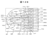
図12Aは、第4実施例に係る光路変換部とアレイ光素子部の側面図である。また、図12Bは、第4実施例に係る光路変換部とアレイ光素子部の上面図である。この実施例では、光路変換部100は、複数の第1の斜めミラー部110-1,…,110-7と、複数の第1の斜めミラー部110-1,…,110-7に対応する複数の第2の斜めミラー部115-1,…,115-7とを備える。この例では、上面から見て光ファイバ1000から斜めに、およそ平行に光信号を引き出すことは行わず、第1の斜めミラー部110-1,…,110-7と対となる複数の第2の斜めミラー部115-1,…,115-7を設けることにより、アレイ光素子部3000の各素子(ここでは、入射部)3010-1,…,3010-7に光信号を入射させる構成である。
FIG. 12A is a side view of the optical path conversion unit and the array optical element unit according to the fourth embodiment. FIG. 12B is a top view of the optical path conversion unit and the array optical element unit according to the fourth embodiment. In this embodiment, the optical path conversion unit 100 corresponds to a plurality of first oblique mirror units 110-1,..., 110-7 and a plurality of first oblique mirror units 110-1,. A plurality of second oblique mirror portions 115-1,..., 115-7. In this example, the optical signals are not drawn obliquely and approximately in parallel from the optical fiber 1000 when viewed from above, and a plurality of second mirrors that are paired with the first oblique mirror portions 110-1,. , 115-7 so that optical signals are incident on the elements (in this case, incident portions) 3010-1,..., 3010-7 of the array optical element unit 3000. is there.
図12Bに示すように、複数の第2の斜めミラー部115-1,…,115-7が、アレイ光素子部3000の各素子3010-1,…,3010-7の位置に対応して並列に配置されている。光ファイバ1000から出射した光信号は、光路変換部100の上面に配置された複数の第1のレンズ部120-1,…,120-7で集光されて光路変換部100に入る。この光信号は、光路変換部100の第1の斜めミラー部110-1,…,110-7で反射され、側面から見て、略同じ高さになるように反射される。このような光路変換は、図12で示したように、光ファイバ1000の各コア部1010-1,…,1010-7の、およそ真下に第1の斜めミラー部110-1,…,110-7を配置することで実現できる。
As shown in FIG. 12B, a plurality of second oblique mirror sections 115-1,..., 115-7 are arranged in parallel corresponding to the positions of the respective elements 3010-1, ..., 3010-7 of the array optical element section 3000. Is arranged. The optical signal emitted from the optical fiber 1000 is collected by the plurality of first lens units 120-1,..., 120-7 disposed on the upper surface of the optical path conversion unit 100 and enters the optical path conversion unit 100. This optical signal is reflected by the first oblique mirror units 110-1,..., 110-7 of the optical path conversion unit 100, and is reflected so as to have substantially the same height when viewed from the side. As shown in FIG. 12, such optical path conversion is performed by the first oblique mirror portions 110-1,..., 110- approximately below the core portions 1010-1,. This can be realized by arranging 7.
なお、この例では、複数の第1の斜めミラー部110-1,…,110-7のそれぞれは、上面から見て異なる角度が付けられている。例えば、図12Bに示すように、第1の斜めミラー部110-7は、第2の斜めミラー部115-1,…,115-7の中で中央にある第2の斜めミラー部115-7に向かって反射させるので、光信号を斜めに引き出す角度は他に比べて小さく設定される。一方、第1の斜めミラー部110-4は、第2の斜めミラー部115-1,…,115-7の中で一番外側にある第2の斜めミラー部115-4に向かって反射させるので、光信号を斜めに引き出す角度は、第1の斜めミラー部110-7の場合と比べて大きく設定される。このように、対応する第2の斜めミラー部115-1,…,115-7の位置に合わせて、複数の第1の斜めミラー部110-1,…,110-7のそれぞれの反射面の角度を設定する。このように設定することで、複数の第1の斜めミラー部110-1,…,110-7は、上面から見て反射した光信号の光路150-1,…,150-7の間隔を広げて、複数の第2の斜めミラー部115-1,…,115-7に向かって反射させることができる。
In this example, each of the plurality of first oblique mirror portions 110-1,..., 110-7 has a different angle when viewed from the top. For example, as shown in FIG. 12B, the first oblique mirror unit 110-7 includes the second oblique mirror unit 115-7 at the center of the second oblique mirror units 115-1,. The angle at which the optical signal is extracted obliquely is set smaller than the others. On the other hand, the first oblique mirror unit 110-4 reflects toward the outermost second oblique mirror unit 115-4 among the second oblique mirror units 115-1, ..., 115-7. Therefore, the angle at which the optical signal is extracted obliquely is set to be larger than that in the case of the first oblique mirror unit 110-7. As described above, the reflection surfaces of the plurality of first oblique mirror portions 110-1,..., 110-7 are respectively matched with the positions of the corresponding second oblique mirror portions 115-1,. Set the angle. By setting in this way, the plurality of first oblique mirror portions 110-1,..., 110-7 widen the intervals of the optical paths 150-1,. Thus, the light can be reflected toward the plurality of second oblique mirror portions 115-1,..., 115-7.
また、複数の第1の斜めミラー部110-1,…,110-7は、側面から見て同じ高さで反射される。側面から見て同じ高さでかつ上面から見て広がる方向に引き出された光信号は、複数の第2の斜めミラー部115-1,…,115-7によって、略真下に光路変換される。すなわち、複数の第2の斜めミラー部115-1,…,115-7は、複数の第1の斜めミラー部110-1,…,110-7で反射された複数の光信号を、複数の光信号の光路が互いに平行になるように反射させて、前記アレイ光素子の各素子に入射させる。このような光路変換は、複数の第2の斜めミラー部115-1,…,115-7のそれぞれの反射面に、上面から見て異なる角度を付けることによって実現できる。複数の第2の斜めミラー部115-1,…,115-7によって反射された光信号は、第2のレンズ部130-1,…,130-7で集光され、アレイ光素子部3000の各素子3010-1,…,3010-7に入射する。なお、アレイ光素子部3000が発光素子の場合も、上述した光路を逆に辿って実現される。
Further, the plurality of first oblique mirror portions 110-1,..., 110-7 are reflected at the same height when viewed from the side. The optical signals drawn out in the same height as viewed from the side and extending in the direction viewed from the upper surface are optically path-converted almost directly by the plurality of second oblique mirror portions 115-1,..., 115-7. That is, the plurality of second oblique mirror units 115-1,..., 115-7 receive the plurality of optical signals reflected by the plurality of first oblique mirror units 110-1,. The optical signals are reflected so that their optical paths are parallel to each other, and are incident on each element of the array optical element. Such optical path conversion can be realized by giving different angles to the reflecting surfaces of the plurality of second oblique mirror portions 115-1,..., 115-7 when viewed from above. The optical signals reflected by the plurality of second oblique mirror portions 115-1,..., 115-7 are collected by the second lens portions 130-1,. It enters each element 3010-1,..., 3010-7. In addition, when the array optical element unit 3000 is a light-emitting element, the above-described optical path is traced in reverse.
本実施例では、アレイ光素子部3000の各素子(入射部あるいは出射部)3010-1,…,3010-7のピッチ間隔が光ファイバ1000のコア部1010-1,…,1010-7から斜めに引き出した光信号の光路の間隔よりも広い場合に、第2実施例のように凹レンズ部200-1及び凸レンズ部200-3などの別の部材を用いることなく、光ファイバ1000とアレイ光素子部3000との光結合が可能になる。例えば、別部材を用いて光信号の光路の間隔を広げる場合、材料ごとの熱膨張率の影響なども考慮する必要があるが、本実施例では、そのような影響を考慮する必要がない。
In this embodiment, the pitch interval of each element (incident part or outgoing part) 3010-1,..., 3010-7 of the array optical element part 3000 is oblique from the core parts 1010-1,. When the distance between the optical paths of the optical signals drawn out to the optical fiber is wider, the optical fiber 1000 and the array optical element can be used without using another member such as the concave lens portion 200-1 and the convex lens portion 200-3 as in the second embodiment. Optical coupling with the unit 3000 is possible. For example, when the distance of the optical path of the optical signal is increased using another member, it is necessary to consider the influence of the coefficient of thermal expansion for each material. However, in this embodiment, it is not necessary to consider such influence.
<第5実施例>
本実施例では、ここでは、アレイ光素子部3000が発光素子の場合を例として説明する。例えば、アレイ光素子部3000は、基板4000上に半田などを介して接合されているエッジエミッタである。図13Aは、第5実施例に係る光路変換部とアレイ光素子部の側面図である。また、図13Bは、第5実施例に係る光路変換部とアレイ光素子部の上面図である。なお、図13Bの上面図において、第1の斜めミラー部110-1,…,110-7は、長方形で簡略的に示されている。
<Fifth embodiment>
In this embodiment, the case where the array optical element unit 3000 is a light emitting element will be described as an example. For example, the array optical element unit 3000 is an edge emitter joined to the substrate 4000 via solder or the like. FIG. 13A is a side view of the optical path conversion unit and the array optical element unit according to the fifth embodiment. FIG. 13B is a top view of the optical path conversion unit and the array optical element unit according to the fifth embodiment. In the top view of FIG. 13B, the first oblique mirror portions 110-1,..., 110-7 are simply shown as rectangles.
本実施例では、アレイ光素子部3000の各素子(ここでは、出射部)3010-1,…,3010-7から出射した光信号が、第2のレンズ部130-1,…,130-7で集光され、側面から見て、略横方向に進む。その後、複数の光信号は、複数の第1の斜めミラー部110-1,…,110-7によって反射される。複数の第1の斜めミラー部110-1,…,110-7によって反射された複数の光信号は、略真上に、且つ、複数の光信号の光路が互いに略平行になるように進む。その後、複数の光信号は、複数の第1のレンズ部120-1,…,120-7で集光されて、光ファイバ1000の複数のコア部1010-1,…,1010-7に入射する。
In the present embodiment, the optical signals emitted from the respective elements (here, the emitting units) 3010-1,..., 3010-7 of the array optical element unit 3000 are converted into the second lens units 130-1,. The light is collected by and travels in the horizontal direction when viewed from the side. Thereafter, the plurality of optical signals are reflected by the plurality of first oblique mirror portions 110-1,..., 110-7. The plurality of optical signals reflected by the plurality of first oblique mirror sections 110-1,..., 110-7 travel so that they are substantially directly above and the optical paths of the plurality of optical signals are substantially parallel to each other. Thereafter, the plurality of optical signals are collected by the plurality of first lens portions 120-1,..., 120-7, and are incident on the plurality of core portions 1010-1,. .
本実施例では、アレイ光素子部3000の各素子)3010-1,…,3010-7がエッジエミッタにおける入射部である場合においても、光ファイバ1000とアレイ光素子部3000との光結合が可能になる。
In this embodiment, the optical fiber 1000 and the array optical element unit 3000 can be optically coupled even when each element 3010-1,..., 3010-7 of the array optical element unit 3000 is the incident part of the edge emitter. become.
<第6実施例>
図14Aは、第6実施例に係る光路変換部とアレイ光素子部の側面図である。また、図14Bは、第6実施例に係る光路変換部とアレイ光素子部の上面図である。なお、図14Bの上面図において、第1の斜めミラー部110-1,…,110-7は、長方形で簡略的に示されている。ここでは、アレイ光素子部3000が受光素子の場合を例として説明する。
<Sixth embodiment>
FIG. 14A is a side view of the optical path conversion unit and the array optical element unit according to the sixth embodiment. FIG. 14B is a top view of the optical path conversion unit and the array optical element unit according to the sixth embodiment. In the top view of FIG. 14B, the first oblique mirror portions 110-1,..., 110-7 are simply shown as rectangles. Here, the case where the array optical element unit 3000 is a light receiving element will be described as an example.
この実施例では、光路変換部100の第2の斜めミラー部115が、複数の光信号を2つの方向に分岐させる光路分岐部117を備える。例えば、光路分岐部117を斜めハーフミラー部とすることにより、光信号を2つに分岐させ、一方の光信号は主信号としてアレイ光素子部3000に入射させ、もう一方の光信号を例えば光パワーなどのモニタ用の信号として処理する。光路分岐部117の例としては、透過率を適宜変更した部分透過ミラーを用いることができる。これにより、光信号を反射させつつ、光信号をそのまま透過させて直進させることが可能となる。なお、光路分岐部117は2方向に光信号を分岐できればよく、ミラーを用いるなど他の構成によって実現してもよい。
In this embodiment, the second oblique mirror unit 115 of the optical path conversion unit 100 includes an optical path branching unit 117 that branches a plurality of optical signals in two directions. For example, by making the optical path branching portion 117 an oblique half mirror portion, an optical signal is branched into two, one optical signal is incident on the array optical element portion 3000 as a main signal, and the other optical signal is, for example, optical It is processed as a monitor signal such as power. As an example of the optical path branching portion 117, a partial transmission mirror with the transmittance changed as appropriate can be used. Thereby, it is possible to transmit the optical signal as it is and to go straight while reflecting the optical signal. The optical path branching unit 117 only needs to be able to branch an optical signal in two directions, and may be realized by another configuration such as using a mirror.
光ファイバ1000から出射した光信号は、光路変換部100の上面に配置された第1のレンズ部120-1,…,120-7で集光されて、光路変換部100に入る。この光信号は、光路変換部100の複数の第1の斜めミラー部110-1,…,110-7で反射され、側面から見て、略同じ高さになるように直角に反射される。このような光路変換は、図14Aで示したように、光ファイバ1000の各コア部1010-1,…,1010-7の、およそ真下に複数の第1の斜めミラー部110-1,…,110-7を配置することで実現できる。このように側面から見て同じ高さで、上面から見て斜めに概平行に引き出された光信号は、第2の斜めミラー部115の光路分岐部117によって分岐される。分岐された一方の光信号は、主信号としてアレイ光素子部3000に入射し、もう一方の光信号は、そのまま横方向に進み、例えば光パワーなどのモニタ用の信号として処理することが可能となる。
The optical signal emitted from the optical fiber 1000 is collected by the first lens units 120-1,..., 120-7 disposed on the upper surface of the optical path conversion unit 100 and enters the optical path conversion unit 100. This optical signal is reflected by the plurality of first oblique mirror units 110-1,..., 110-7 of the optical path conversion unit 100, and is reflected at a right angle so as to have substantially the same height when viewed from the side. As shown in FIG. 14A, such optical path conversion is performed by a plurality of first oblique mirror portions 110-1,..., Approximately directly below each core portion 1010-1,. This can be realized by arranging 110-7. In this way, the optical signal with the same height when viewed from the side and withdrawn substantially in parallel obliquely when viewed from the upper surface is branched by the optical path branching portion 117 of the second oblique mirror portion 115. One of the branched optical signals enters the array optical element unit 3000 as a main signal, and the other optical signal proceeds in the horizontal direction as it is, and can be processed as a monitoring signal such as optical power. Become.
なお、本発明は上記した実施例に限定されるものではなく、様々な変形例が含まれる。例えば、上記した実施例は本発明を分かりやすく説明するために詳細に説明したものであり、必ずしも説明した全ての構成を備えるものに限定されるものではない。また、ある実施例の構成の一部を他の実施例の構成に置き換えることが可能であり、また、ある実施例の構成に他の実施例の構成を加えることも可能である。また、各実施例の構成の一部について、他の構成の追加・削除・置換をすることが可能である。
In addition, this invention is not limited to the above-mentioned Example, Various modifications are included. For example, the above-described embodiments have been described in detail for easy understanding of the present invention, and are not necessarily limited to those having all the configurations described. Further, a part of the configuration of one embodiment can be replaced with the configuration of another embodiment, and the configuration of another embodiment can be added to the configuration of one embodiment. Further, it is possible to add, delete, and replace other configurations for a part of the configuration of each embodiment.