WO2014049796A1 - 通信装置および電子部品実装機 - Google Patents
通信装置および電子部品実装機 Download PDFInfo
- Publication number
- WO2014049796A1 WO2014049796A1 PCT/JP2012/074985 JP2012074985W WO2014049796A1 WO 2014049796 A1 WO2014049796 A1 WO 2014049796A1 JP 2012074985 W JP2012074985 W JP 2012074985W WO 2014049796 A1 WO2014049796 A1 WO 2014049796A1
- Authority
- WO
- WIPO (PCT)
- Prior art keywords
- unit
- communication
- image data
- crc value
- data
- Prior art date
- Legal status (The legal status is an assumption and is not a legal conclusion. Google has not performed a legal analysis and makes no representation as to the accuracy of the status listed.)
- Ceased
Links
Images



Classifications
-
- H—ELECTRICITY
- H03—ELECTRONIC CIRCUITRY
- H03M—CODING; DECODING; CODE CONVERSION IN GENERAL
- H03M13/00—Coding, decoding or code conversion, for error detection or error correction; Coding theory basic assumptions; Coding bounds; Error probability evaluation methods; Channel models; Simulation or testing of codes
- H03M13/35—Unequal or adaptive error protection, e.g. by providing a different level of protection according to significance of source information or by adapting the coding according to the change of transmission channel characteristics
- H03M13/356—Unequal error protection [UEP]
-
- H—ELECTRICITY
- H03—ELECTRONIC CIRCUITRY
- H03M—CODING; DECODING; CODE CONVERSION IN GENERAL
- H03M13/00—Coding, decoding or code conversion, for error detection or error correction; Coding theory basic assumptions; Coding bounds; Error probability evaluation methods; Channel models; Simulation or testing of codes
- H03M13/03—Error detection or forward error correction by redundancy in data representation, i.e. code words containing more digits than the source words
- H03M13/05—Error detection or forward error correction by redundancy in data representation, i.e. code words containing more digits than the source words using block codes, i.e. a predetermined number of check bits joined to a predetermined number of information bits
- H03M13/09—Error detection only, e.g. using cyclic redundancy check [CRC] codes or single parity bit
-
- H—ELECTRICITY
- H03—ELECTRONIC CIRCUITRY
- H03M—CODING; DECODING; CODE CONVERSION IN GENERAL
- H03M13/00—Coding, decoding or code conversion, for error detection or error correction; Coding theory basic assumptions; Coding bounds; Error probability evaluation methods; Channel models; Simulation or testing of codes
- H03M13/63—Joint error correction and other techniques
- H03M13/635—Error control coding in combination with rate matching
-
- H—ELECTRICITY
- H04—ELECTRIC COMMUNICATION TECHNIQUE
- H04L—TRANSMISSION OF DIGITAL INFORMATION, e.g. TELEGRAPHIC COMMUNICATION
- H04L1/00—Arrangements for detecting or preventing errors in the information received
- H04L1/004—Arrangements for detecting or preventing errors in the information received by using forward error control
- H04L1/0056—Systems characterized by the type of code used
- H04L1/0061—Error detection codes
Definitions
- the present invention relates to a communication device that performs communication for image data, and an electronic component mounting machine including the communication device.
- Patent Document 1 discloses a configuration in which image data is communicated between an imaging device and a control device in an electronic component mounting machine that mounts electronic components on a substrate.
- This electronic component mounting machine recognizes a board based on image data obtained by imaging by an imaging device, and aims to improve the positioning accuracy of a head that sucks the component.
- a communication error (error in the communication path) may occur due to noise or the like. If there is an error in the transmitted image data, processing based on this image data is not performed properly, and the above-described electronic component mounter may reduce the accuracy of board recognition.
- error detection methods such as a parity check method and a CRC (Cyclic Redundancy Check) method are known.
- CRC Cyclic Redundancy Check
- Patent Document 2 discloses a method for detecting a communication error by combining a parity method and a CRC method.
- the CRC method is a method of calculating a CRC value (check code) using a predetermined CRC polynomial. Therefore, the CRC method is more effective in detecting packet communication errors, burst errors, and random errors than the parity method.
- the CRC value is added to the data as redundant bits, so the data size increases and the time required for communication increases.
- the transmitted data has a variable length. For this reason, for example, it is necessary to add a predetermined command or to add a CRC value for each fixed-length frame so that the reception side can identify the location of the added CRC value. However, even if such measures are taken, it is assumed that the above command and one frame have been correctly transmitted. Therefore, the CRC method may not be suitable as an error detection method in a communication method other than packet communication.
- the present invention has been made in view of such circumstances, and an object of the present invention is to provide a communication device capable of error detection by the CRC method without changing the data size, and an electronic component mounting machine including the communication device. To do.
- the communication device is a communication device that performs communication for image data, and includes a plurality of continuous pixels of the image data as unit data, and is configured by each upper bit in the unit data.
- a CRC value calculation unit for calculating the CRC value of the upper bit group using a preset CRC polynomial, and the difference between the CRC value and the sum of the lower bit group composed of each lower bit in the unit data
- a difference calculation unit to calculate, and a lower bit inversion unit that inverts one or a plurality of the lower bits selected by the difference from the lower bit group, and makes the sum of the lower bit group after the inversion equal to the CRC value; .
- the communication apparatus executes image data change processing (image processing) so that the CRC value is included in the lower bit group of the image data. That is, since the communication device does not add the CRC value as redundant bits to the image data, it can transmit the image data without changing the data size. In addition, since the CRC value can be obtained from the sum of the lower bit groups on the image data receiving side, it is possible to detect errors in comparison with the CRC value of the upper bit group by the same procedure as in the normal CRC method. is there. As described above, the CRC method, which is advantageous in that a burst error can be detected as compared with the parity method, can be applied to image data communication without increasing the time required for communication.
- image processing image processing
- the lower bits are inverted by the difference between the sum of the lower bit groups and the CRC value, so that some information in the image data is changed.
- the image data is indicated by luminance or color by bit data of each pixel, for example. Even if the lower bit of the bit data is inverted, the luminance or color of the pixel changes only in several stages, and the influence on the entire image data is small. That is, the communication device suppresses the influence on the processing using the image data on the receiving side by performing image processing so that the CRC value is embedded in the lower bit group.
- the communication apparatus calculates a CRC value for the unit data constituting one line, and performs image processing so that this CRC value is embedded in the lower bit group. Therefore, the receiving side can perform CRC method error detection based on the number of data for one line in the transmitted image data. As described above, the communication apparatus can perform error detection processing without adding a delimiter or the like to the image data, and therefore can perform image processing efficiently.
- the lower bit inversion unit preferentially selects and inverts the lower bits located at both ends of one line. According to such a configuration, the lower bits inverted by the lower bit inversion unit are biased toward both ends of one line. Since the communication apparatus performs image processing so that the CRC value is embedded in the lower bit group, a part of the information in the image data is changed as long as the difference between the CRC value and the sum of the lower bit group is not zero. However, on the receiving side, the area required for the image data may be sufficient only at the center, for example, the subject is in the center of the image data. In such a case, it is possible to further suppress the influence on the processing using the image data on the receiving side by biasing the lower bits inverted by the lower bit inverting unit toward both ends of one line.
- the lower bit inversion unit selects and inverts the plurality of lower bits so as to be equidistant from the plurality of lower bits. According to such a configuration, the lower bits inverted by the lower bit inversion unit are distributed in the lower bit group. Therefore, since it is possible to suppress the inversion of consecutive lower bits, the influence on the image data due to the inversion can be suppressed.
- the difference calculation unit divides the CRC value represented by a binary system into a plurality of bit strings and divides the lower bit group into a plurality of blocks corresponding to the bit strings.
- a set difference calculation unit that calculates a difference between the sub-CRC value indicated by the bit string and the sub-CRC value indicated by the bit string for each set of the bit string and the block.
- the lower bit inversion unit inverts one or a plurality of the lower bits selected by the difference calculated for the set from the block of the set, and calculates the subtotal of the lower bits after the inversion. By making it equal to the sub CRC value, the sum of the lower bit groups is made equal to the CRC value and divided by the dividing unit.
- the division number of the CRC value and the lower bit group, the number of the lower bits contained in the block is set to be the number of digits of bit strings by two raised to the power value above that.
- the communication apparatus can perform image processing so that the CRC value calculated using the CRC polynomial is embedded in the lower bit group even when the degree of the CRC polynomial is increased.
- the CRC method it is possible to improve the accuracy of error detection by increasing the degree of the CRC polynomial.
- the degree of the CRC polynomial increases, the number of digits of the CRC value indicated by the binary system also increases.
- the communication apparatus of the present invention since the CRC value is embedded in the lower bit group, if the CRC value exceeds the number of lower bits included in the lower bit group, the CRC value cannot be expressed in the lower bit group. .
- each bit string of the CRC value obtained by dividing each block can be expressed. Therefore, the communication apparatus can perform image processing so as to embed a CRC value in the lower bit group. Therefore, the accuracy of error detection by the CRC method can be improved by increasing the degree of the CRC polynomial.
- the communication apparatus further includes a communication unit that performs communication based on the camera link standard.
- CRC method error detection can be performed for communication targeting image data even in the camera link standard.
- the camera link standard is a communication method that is not packet communication, and the data to be transmitted has a variable length. Therefore, application of error detection by the CRC method is not suitable.
- the communication apparatus of the present invention since the CRC value is embedded in the lower bit group, it is not necessary to add a predetermined command for specifying the location of the CRC value in the image data, and the CRC value is used. This is particularly useful because error detection can be applied to communications compliant with the camera link standard.
- An electronic component mounting machine includes the communication device according to any one of the first to seventh aspects, an imaging device that images a subject and records image data, and the communication device of the imaging device.
- An electronic component mounting comprising: a control device that is communicably connected, acquires the image data sent from the communication device, and controls mounting of the electronic component based on the image data and a pre-stored control program
- the control device calculates a CRC value of the upper bit group in the unit data among the acquired image data using the CRC polynomial, and the lower CRC in the unit data.
- a control-side difference calculation unit that calculates a difference between the sum of bit groups and the CRC value, and a communication error detection unit that detects a communication error based on the calculated difference. That.
- the electronic component mounter can detect a communication error by the communication error detection unit, so that it is possible to verify whether there is an error in the transmitted image data. Therefore, the electronic component mounting machine can prevent the electronic component mounting from being controlled based on erroneous image data. As a result, when the control device requests the imaging device to execute imaging and transmit image data again, control using error-free image data becomes possible, and the mounting accuracy of the electronic component mounting machine is improved. be able to.
- the embodiment exemplifies a configuration in which a communication device is used for information transmission between a control device and an imaging device that are communicably connected in an electronic component mounting machine.
- the electronic component mounting machine 1 is a device that mounts a plurality of electronic components on a printed circuit board, for example, in an integrated circuit manufacturing process. Solder is applied to the mounting position of the electronic component by the cream solder printing machine, and the printed circuit board is sequentially transported through a plurality of mounting machines to mount the electronic component. Thereafter, the printed circuit board on which the electronic components are mounted is transported to a reflow furnace and soldered to constitute an integrated circuit.
- the camera 3 is an imaging device for FA incorporated in the electronic component mounting machine 1.
- the electronic component mounting machine 1 includes a mounting machine control device 2 and a camera 3 as shown in FIG.
- the mounting machine control device 2 and the camera 3 are communicably connected by a communication cable 4 so that various signals can be transmitted and received.
- the communication apparatus includes the CPU 10 of the mounter control apparatus 2, the CPU 40 of the camera 3, and the communication cable 4. This communication apparatus detects a communication error due to noise or the like using a CRC value (check code) in order to detect an error in image data transmitted from the camera 3 to the mounter control apparatus 2. Details of communication error detection will be described later.
- the communication device performs communication conforming to the camera link standard for image data.
- the camera link standard is serial communication that transmits image data by LVDS (Low Voltage Differential Signaling).
- the camera link standard is different from packet communication in which data is divided into packets of a certain length and transmitted, and the transmitted data has a variable length.
- the mounting machine control device 2 is a device that executes various control processes.
- the mounting machine control device 2 includes a CPU 10 that forms part of a communication device, and a storage device 20.
- the storage device 20 is configured by an optical drive device such as a hard disk device or a flash memory.
- the storage device 20 stores a control program for operating the electronic component mounting machine 1, image data transferred from the camera 3 to the CPU 10 via the communication cable 4, temporary data for processing by the image processing unit 15, and communication errors.
- a CRC polynomial used for detection is stored.
- the CPU 10 of the mounting machine control device 2 includes a communication unit 11, a CRC value calculation unit 12, a difference calculation unit 13, a communication error detection unit 14, and an image processing unit 15.
- the CPU 10 inputs information output from various sensors provided in the electronic component mounting machine 1 and image data transferred from the camera 3. Then, the CPU 10 mounts an electronic component mounter so that the electronic component is appropriately mounted on the printed circuit board based on the control program stored in the storage device 20, information from various sensors, the processing result by the image processing unit 15, and the like. 1 axis motors and devices are controlled.
- the communication unit 11 on the mounting machine side controls communication according to various communication protocols and communication standards according to a predetermined communication mode set in the mounting machine control device 2.
- the communication unit 11 performs communication based on the camera link standard with the camera 3 in a communication form of a wired communication path formed by the communication cable 4 or the like.
- the CPU 10 constituting the communication device of the electronic component mounting machine 1 performs error detection using the CRC value.
- the CRC value calculation unit 12 on the mounting machine side uses a plurality of pixels in the acquired image data as unit data, and calculates a CRC value of a part of the unit data using a CRC polynomial stored in the storage device 20. .
- the difference calculation unit 13 calculates the difference between the CRC value and the total sum of the parts excluding the part for which the CRC value is calculated in the unit data.
- the communication error detection unit 14 detects a communication error based on the calculated difference. The details of the “unit data”, the control side CRC value calculation unit 12, the difference calculation unit 13, and the communication error detection unit 14 will be described later.
- the image processing unit 15 acquires image data captured by the camera 3 and executes image processing according to the application.
- This image processing includes, for example, processing such as binarization of image data, filtering, and hue extraction, and recognition of the presence / absence of a subject and position information based on a specific shape or mark from the processed image data Processing is included. Further, in order to reduce the load on the image processing unit 15, for example, the processing of the image data in the image processing is performed on the camera 3 side, and only the above recognition processing is performed by the mounting machine control device 2. The image processing unit 15 may perform this.
- the camera 3 includes an optical unit 30, a CPU 40, and a storage device 50.
- the optical unit 30 has a configuration in which subject light is imaged on an image sensor 32 by a lens unit 31 including a lens and a lens holding member.
- the image sensor 32 is mounted on the circuit board so as to be perpendicular to the optical axis of the lens unit 31.
- the image sensor 32 is an image sensor such as a CCD (Charge-Coupled Device) or a CMOS (Complementary-Metal-Oxide-Semiconductor).
- the CPU 40 of the camera 3 operates the optical unit 30 on the basis of a control signal input from the mounting machine control device 2 to perform imaging, and transfers the image data acquired by the imaging to the mounting machine control device 2 It is the control apparatus which comprises a part of. More specifically, the CPU 40 controls the optical unit 30 based on a signal input from the outside or a control command input from the mounting machine control device 2, and forms an image on the imaging surface of the imaging element 32 by the lens unit 31. The subject is imaged by converting the signal charge generated according to the intensity of the light to a digital signal. The CPU 40 converts the image data into image data based on the digital signal.
- the CPU 40 includes a communication unit 41, a CRC value calculation unit 42, a difference calculation unit 43, and a lower bit inversion unit 44.
- the communication unit 41 controls communication according to various communication protocols and communication standards according to a predetermined communication mode set in the camera 3. In this embodiment, the communication unit 41 communicates with the mounter control apparatus 2 via the communication cable 4 in accordance with the camera link standard. Further, as described above, since the electronic component mounter 1 performs error detection in communication using the CRC value, an image in which the CRC value is embedded in the image data before the communication unit 41 transmits the image data. Processing is in progress.
- the CRC value calculation unit 42 on the camera side uses a plurality of continuous pixels in the image data as unit data, and sets a CRC value of an upper bit group constituted by each upper bit in the unit data as a preset CRC polynomial. Calculate using.
- the image data is indicated by luminance or color by bit data of each pixel, for example.
- the “sequential pixels” (unit data) is a predetermined number of pixels that continue in a horizontal line of image data, and may be divided into one line or a plurality of lines. Good.
- the unit data and the unit data for which the CRC value is calculated by the CRC value calculation unit 12 on the mounting machine side are composed of a plurality of pixels included in the same range in the image data.
- the CPU 40 handles bit data of each pixel separately on the upper side and the lower side.
- each pixel is data consisting of n bits
- the upper bit is the bit string from the most significant to the (n ⁇ 1) th bit
- the lower bit is the least significant n The 1st bit.
- the “upper bit group” in the unit data is a set of upper bits of each pixel included in the unit data, and is configured by connecting the upper bits in the order of consecutive pixels, for example.
- the CRC polynomial used for the calculation of the CRC value calculation unit 42 is a generator polynomial used for calculating a CRC value in a general CRC error detection process.
- the CRC value is a check code in CRC error detection processing, and is a value corresponding to a remainder when data to be communicated is divided by a CRC polynomial.
- a general CRC system when error detection is applied to communication, data obtained by adding a CRC value as a redundant bit to communication target data is used as transmission data.
- the difference calculation unit 43 on the camera side calculates the difference between the sum of the lower bit groups formed by the lower bits in the unit data and the CRC value.
- the “lower bit group” in the unit data is an aggregate of lower bits of each pixel included in the unit data, and is configured by connecting lower bits in the order of consecutive pixels, for example.
- the “sum of lower bit groups” is a value obtained by simply adding a plurality of lower bits included in the lower bit group. That is, the sum of the lower bit groups can take a value from 0 to 1024 in decimal notation when the unit data is one line of image data and one line is 1024 pixels.
- the lower bit inversion unit 44 inverts one or a plurality of lower bits selected by the difference from the lower bit group.
- the lower bit inversion unit 44 selects five lower bits having a value of 0 from the lower bit group, and inverts them so that the value of the five lower bits becomes 1. In this way, the lower bit inversion unit 44 makes the sum of the lower bit groups after inversion equal to the CRC value.
- the lower bit inversion unit 44 selects only the lower bit having a value of 1 from the lower bit group, and the selected lower bit value becomes 0. Invert like so. Further, when selecting the lower bits, the lower bit inversion unit 44 prioritizes the lower bits located at both ends of one line when the unit data constitutes one line of the image data in this embodiment. And reverse. That is, when the lower bit inversion unit 44 selects a lower bit having a value of 0 from the lower bit group, the lower bit having a value of 0 is sequentially searched from both ends of one line and selected based on the search result. I do.
- the storage device 50 of the camera 3 includes a nonvolatile ROM 51 and a volatile RAM 52.
- the ROM 51 stores a program such as a driver for the CPU 40 to control the optical unit 30, initial setting data, a CRC polynomial used for calculating a CRC value, and the like.
- the RAM 52 temporarily stores the CRC value calculated by the CRC value calculation unit 42, the difference calculated by the difference calculation unit 43, and the upper and lower bits of the image data.
- FIGS. CPU40 which comprises a communication apparatus in the camera 3 image
- the image data 5 acquired by the camera 3 is composed of 1024 pixels per line as shown in FIG.
- the communication device performs image processing for embedding a CRC value for error detection in the image data 5, and transfers the image data 5 to the CPU 10 on the mounting machine side.
- a CRC value is calculated using a predetermined number of consecutive pixels as unit data Ln. That is, the unit data Ln is a minimum unit pixel that is an object of error detection by the communication apparatus.
- the number of pixels included in the unit data Ln can be set as appropriate. In the present embodiment, the number of pixels is 1024 pixels constituting one line.
- the CRC value calculation unit 42 calculates the CRC value R (x) of the upper bit group Sh in the unit data Ln using the CRC polynomial G (x) (S12).
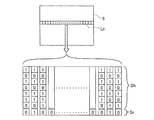
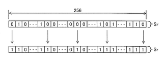
- FIG. 3 schematically shows a state in which each pixel in the unit data Ln is expanded into bit data.
- the upper bit group Sh of the unit data Ln is a collection in which the upper 7 bits of each pixel are connected in a sequential order, and is bit data having 7168 digits.
- the lower-order bit group Sr of the unit data Ln is an aggregate obtained by concatenating the least significant 1 bit of each pixel in a sequential order, and is bit data having 1024 digits.
- the CRC value calculation unit 42 divides the upper bit group Sh by the CRC polynomial G (x), and calculates the remainder of the division as the CRC value R (x).
- the CPU 40 associates the calculated CRC value R (x) with the upper bit group Sh and stores it in the RAM 52 of the storage device 50.
- the difference calculating unit 43 calculates the sum M1 of the lower bit group Sr of the unit data Ln (S13).
- the sum M1 of the lower bit group Sr corresponds to the quantity of lower bits whose value is 1 in the lower bit group.
- the lower bit inversion unit 44 selects a lower bit to be inverted from the lower bit group Sr based on the calculated difference ⁇ 1 (S15). At this time, when the difference ⁇ 1 is a positive number ( ⁇ 1> 0), the lower-order bit inversion unit 44 determines that the sum M1 of the lower-order bit group Sr is smaller than the CRC value R (x) (M1 ⁇ R (x) ), The lower bit having a value of 0 is selected from the lower bit group Sr by the difference ⁇ 1. Further, when the difference ⁇ 1 is a negative number ( ⁇ 1 ⁇ 0), the lower bit inversion unit 44 has a sum M1 of the lower bit group Sr larger than the CRC value R (x) (M1> R (x)). A lower bit having a value of 1 is selected from the lower bit group Sr by the difference ⁇ 1.
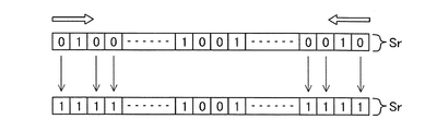
- the lower bit inversion unit 44 preferentially selects the lower bits located at both ends of one line as shown in FIG. Like to do. That is, the selected lower bits are biased toward the head side and the tail side in the unit data Ln.
- the lower bit inversion unit 44 inverts the value of the selected one or more lower bits from 0 to 1 or from 1 to 0 (S16). Thus, the lower bit inversion unit 44 makes the sum M2 of the lower bit group Sr after inversion equal to the CRC value R (x). By such image processing, the luminance of the pixel having one or more inverted low-order bits changes by one step.
- the communication apparatus does not add the CRC value as a redundant bit as in the general CRC system, but embeds the CRC value R (x) in the lower bit group of the unit data Ln so that the data size does not change.
- the CPU 40 stores the inverted lower bit group Sr in the RAM 52 of the storage device 50.
- the communication unit 41 transfers the unit data Ln to the mounter control device 2 through communication conforming to the camera link standard (S17). More specifically, the communication unit 41 generates unit data Ln by combining corresponding upper bits and lower bits from the upper bit group Sh and the lower bit group Sr stored in the RAM 52. The communication unit 41 transfers the unit data Ln by adding a stop bit to the end of the unit data Ln as necessary.
- the communication device determines whether or not the transfer to the mounter control device 2 has been completed for all the lines in the image data 5 (S18). If the transfer has not been completed (S18: No), the process proceeds to the next line in the image data 5, and the embedding of the CRC value R (x) in the line and the transfer to the mounter control device 2 are executed. To do. As described above, the communication device embeds the CRC value R (x) in each line of the image data 5 by repeating S12 to S17, and confirms that the transfer request of the image data from the mounter control device 2 is continued. As a condition, the image data 5 is sequentially transferred. When the transfer is completed for all the lines in the image data 5 (S18: Yes), the transfer process of the image data 5 by the communication device is ended.
- image data error detection processing by the communication device of the electronic component mounting machine 1 will be described with reference to FIG. CPU10 which comprises a communication apparatus in the mounting machine control apparatus 2 acquires the image data 5 transmitted from the camera 3, as shown in FIG. 5 (S21). As described above, the communication device sets a plurality of pixels constituting one line of the image data 5 as unit data Ln, and executes error detection processing in communication for each unit data Ln.
- the CPU 10 divides the unit data Ln in the transmitted image data 5 into an upper bit group Sh and a lower bit group Sr. Then, the CRC value calculation unit 12 on the control side calculates the CRC value R (x) of the upper bit group Sh using the CRC polynomial G (x) (S22). Since the process of S22 by the CRC value calculation unit 12 is substantially the same as the process of S12 by the CRC value calculation unit 42 on the camera 3 side, detailed description thereof is omitted.
- the CRC polynomial G (x) is stored in advance in the storage device 20 of the mounting machine control device 2 and is the same as that stored in the storage device 50 of the camera 3.
- the communication error detection unit 14 detects a communication error based on the calculated difference (S25). If there is no influence of noise or the like in the communication of the image data 5, the CRC value R (x) calculated in S22 is the CRC value R calculated on the camera 3 side before the image data 5 is transferred. Equivalent to (x). Similarly, the sum M3 of the lower bit group Sr calculated in S23 has the same value as the sum M2 of the lower bit group Sr in which some lower bits are inverted before the transfer of the image data 5. Therefore, the communication error detection unit 14 detects a communication error when the difference calculated in S25 is other than 0, that is, the sum M3 and the difference ⁇ 2 are unequal (M3 ⁇ ⁇ 2).
- the communication device determines whether a communication error is detected in S25 (S26). If no communication error is detected (S26: Yes), it is determined whether or not error detection has been completed for all lines in the image data 5 (S26). If error detection has not been completed for all lines (S26: No), the process proceeds to the next line in the image data 5 and returns to S22. In this way, the communication apparatus sequentially performs error detection on each line of the image data 5 by repeating S22 to S26.
- the communication device ends the error detection process of the image data 5. Then, the mounting machine control device 2 executes image processing according to the application on the image data 5 acquired by the image processing unit 15, for example.
- the communication apparatus notifies the mounter control apparatus 2 that a communication error has occurred (S28), and an error detection process for the image data 5 is performed. Stop and exit. Then, the mounting machine control device 2 sends a control signal to the camera 3 so as to capture an image, and requests the camera 3 to transfer the acquired image data again.
- the communication device performs error detection processing on the acquired image data 5 after the communication between the mounter control device 2 and the camera 3 is completed.
- the communication device sequentially executes error detection processing on the unit data Ln each time the communication unit 11 on the control side acquires the unit data Ln in the image data 5 during communication. May be. By doing in this way, it is possible to speed up detection and handling of communication errors.
- the communication device configured as described above performs error detection processing using the CRC value R (x), but performs image processing so that the CRC value R (x) is embedded in the lower bit group Sr of the image data 5 to be transmitted. It was. That is, since the communication device does not add the CRC value R (x) as a redundant bit to the image data 5, the image data 5 can be transmitted without changing the data size. Further, the mounter control apparatus 2 on the receiving side of the image data 5 can acquire the CRC value R (x) from the sum M3 of the lower bit group Sr, and therefore the upper bit group can be obtained by the same procedure as in the normal CRC method. Error detection can be performed in comparison with the CRC value R (x). As described above, the CRC method, which is advantageous in that a burst error can be detected as compared with the parity method, can be applied to image data communication without increasing the time required for communication.
- the lower bits are inverted by the difference ⁇ 1 between the sum M1 of the lower bit group Sr and the CRC value R (x), so that some information in the image data 5 Will be changed.
- the luminance of the image data 5 is indicated by 8-bit bit data of each pixel. Even if the lower bit of the bit data is inverted, the luminance of the pixel only changes by several steps, and the influence on the entire image data 5 is small. That is, the communication apparatus suppresses the influence on the processing using the image data 5 on the receiving side by performing image processing so that the CRC value R (x) is embedded in the lower bit group Sr.
- the lower bits that can be inverted by the lower bit inversion unit 44 are the least significant bits in the image data 5. Therefore, even if the lower bit inversion unit 44 inverts the lower bit, the change in luminance in the pixel can be reduced. That is, even if the least significant bit of the bit data of each pixel is inverted, the influence on the entire image data 5 can be minimized by only changing the luminance of the pixel by one level. Therefore, the communication apparatus can minimize the influence on the processing using the image data 5 on the receiving side.
- the communication apparatus uses the unit data Ln, which is the minimum unit for error detection, as a plurality of pixels constituting one line in the image data 5. Accordingly, the communication apparatus calculates a CRC value R (x) for the unit data Ln, and performs image processing so that the CRC value R (x) is embedded in the lower bit group Sr. Therefore, the mounting machine control device 2 on the receiving side can perform CRC method error detection based on the number of data for one line in the transmitted image data 5. In this way, the communication device can perform error detection processing without adding a delimiter or the like to the image data 5, and therefore can efficiently perform image processing.
- the lower bit inversion unit 44 preferentially selects lower bits located at both ends of one line when selecting lower bits to be inverted. As a result, the lower bits inverted by the lower bit inversion unit 44 are biased toward both ends of one line. Since the communication apparatus performs image processing so that the CRC value R (x) is embedded in the lower bit group Sr, unless the difference ⁇ 1 between the CRC value R (x) and the lower bit group Sr is M1, the image data 5 Some information is subject to change. However, in the image processing unit 15 of the mounting machine control device 2, the area required for the image data 5 may be sufficient only at the center, for example, the subject is in the center of the image data 5. In such a case, the influence on the processing by the image processing unit 15 can be further suppressed by biasing the lower bits inverted by the lower bit inversion unit 44 toward both ends of one line.
- the communication unit 41 of the camera 3 and the communication unit 11 of the mounter control device 2 constituting the communication device perform communication conforming to the camera link standard.
- the CRC value R (x) is embedded in the lower bit group Sr, it is not necessary to add a predetermined command for specifying the location of the CRC value R (x) in the image data 5.
- the error detection by the CRC method can be preferably applied.
- the illustrated error detection process can perform error detection using the CRC value R (x) effective for burst error detection and the like even if the transmitted data is a camera link standard with variable length. So it is particularly useful.
- the electronic component mounting machine 1 can detect a communication error by the communication error detecting unit 14 of the mounting machine control device 2, it is possible to verify whether there is an error in the transmitted image data 5. Therefore, the electronic component mounting machine 1 can prevent the electronic component mounting from being controlled based on the erroneous image data 5. As a result, the control device requests the imaging device to execute imaging and transmit the image data 5 again, thereby enabling control using the image data 5 without error, and mounting accuracy of the electronic component mounting machine 1. Can be improved.
- ⁇ Second embodiment> A communication apparatus and electronic component mounting machine 101 according to the second embodiment will be described with reference to FIGS.
- the communication device of this embodiment is mainly different from the first embodiment in the process of embedding a CRC value R (x). Since other common configurations are substantially the same as those in the first embodiment, detailed description thereof is omitted. Only the differences will be described below.
- the communication apparatus has a function of performing communication error detection processing using the CRC value R (x).
- the CRC value R (x) is embedded in a part of the image data 5 (lower bit group Sr) so that the data size of the image data 5 does not change. Therefore, in the image processing exemplified in the first embodiment, the CRC value R (x) exceeding the range that can be expressed by the unit data Ln may not be embedded in the lower bit group Sr.
- one line in the image data 5 is 1024. If it is a pixel, the range that can be expressed by the unit data Ln is 0 to 1024. That is, when the CRC value R (x) exceeds 1024, that is, when the number of digits of the CRC value R (x) indicated by the binary system exceeds 10 digits, the CRC value R (x) is added to the lower bit group Sr. Cannot be embedded.
- the unit data Ln in order to increase the range that can be expressed by the unit data Ln, it may be possible to set the lower bits to a plurality of bits from the lower side of the bit data of each pixel, or increase the number of pixels included in the unit data Ln. It is done. However, in the former case, the influence due to the inversion of the lower bits is also increased. In the latter case, the data size of the unit data Ln increases, and there is a possibility that the load of the CRC value R (x) embedding process before the transfer will increase.
- an error detection process corresponding to the CRC value R (x) having an increased number of digits without increasing the data size of the unit data Ln will be described.
- one line of the image data 5 acquired by the camera 3 is composed of 1024 pixels.
- the error detection unit data Ln targeted by the communication device is assumed to be composed of 1024 pixels constituting one line of the image data 5.
- the CRC polynomial G (x) has a bit length set to 33 bits.
- the communication device includes the CPU 100 of the mounter control device 2, the CPU 140 of the camera 3, and the communication cable 4, as shown in FIG.
- the CPU 140 of the camera 3 on the transmission side in the communication of the image data 5 includes a communication unit 41, a CRC value calculation unit 42, a difference calculation unit 143, and a lower bit inversion unit 44.
- the difference calculating unit 143 includes a dividing unit 143a that divides the CRC value R (x) and the lower bit group Sr, and a set difference calculating unit 143b that calculates a difference for each divided set.
- the dividing unit 143a divides the CRC value R (x) indicated by the binary system into a plurality of bit strings L1 to L4 with a predetermined division number P.
- the CRC value R (x) calculated by the CRC value calculation unit 42 has a length of 33 bits when the CRC polynomial G (x) has a bit length of 33 bits. It becomes.
- the division number P is set to 4 (a method for setting the division number P will be described later). That is, the 32-digit CRC value R (x) is divided into 8-bit bit strings L1 to L4 from the upper side as shown in FIG.
- the 8-digit partial CRC values indicated by the bit strings L1 to L4 are sub CRC values R1 to R4.
- the dividing unit 143a divides the lower bit group Sr into a plurality of blocks B1 to B4 with a division number P in association with the bit strings L1 to L4. That is, the lower bit group Sr composed of the least significant bits of 1024 pixels is divided into blocks B1 to B4 each composed of 256 lower bits from the upper side.
- the 32-digit CRC value R (x) can take a value in the range of ⁇ 0 to (2 ⁇ 32) ⁇ when expressed in decimal.
- the set difference calculation unit 134b calculates subtotals N1 to N4 of the lower bits included in the blocks B1 to B4.
- the subtotals N1 to N4 correspond to the number of lower bits whose value is 1 in each of the blocks B1 to B4.
- the lower bit inversion unit 44 selects lower bits from the block B1 of the set S1 by the difference ⁇ 1 calculated for the set S1 by the set difference calculation unit 134b.
- the low-order bits selected by the low-order bit inversion unit 44 have a value of 0 when the difference ⁇ 1 is a positive number (R1> N1) and when the difference ⁇ 1 is a negative number (R1 ⁇ N1). Has a value of 1.
- the lower bit inversion unit 44 selects a plurality of lower bits at equal intervals as shown in FIG. That is, the lower bit inversion unit 44 selects a plurality of lower bits to be distributed as much as possible in the block 1.
- the lower bit inversion unit 44 inverts the value of the selected one or more lower bits from 0 to 1 or from 1 to 0. Similarly, for the other sets S2 to S4, the lower bit inversion unit 44 selects lower bits from the blocks B2 to B4 by the differences ⁇ 2 to ⁇ 4 and inverts the values. As a result, the subtotals N1 ′ to N4 ′ of the blocks B1 to B4 after inversion become equal to the sub CRC values R1 to R4, respectively.
- the CPU 110 of the mounting machine control device 2 on the receiving side in the communication of the image data 5 includes the communication unit 11, the CRC value calculation unit 12, the difference calculation unit 113, the communication error detection unit 14, and the image processing unit 15.
- the difference calculation unit 113 of the mounting machine control apparatus 2 includes a division unit 113a and a set difference calculation unit 113b, and performs substantially the same processing as the difference calculation unit 143 of the camera 3. Therefore, detailed description of the difference calculation unit 113 is omitted.
- the communication apparatus uses the image processing for embedding the CRC value R (x) having 32 digits in the image data 5 and the CRC value R (x) without increasing the data size of the unit data Ln. Error detection processing is possible. This is due to the division of the CRC value R (x) and the lower bit group Sr by the appropriate division number P by the division units 143a and 113a.
- the division number P needs to be set in consideration of the number of digits of the CRC value R (x), the data size of the unit data Ln, and the number of lower bits.
- the division number P is set so that the lower-order bit quantity T1 included in the block B1 is equal to or greater than the value obtained by raising 2 to the number of digits U1 of the bit string L1 (T1 ⁇ 2 ⁇ U1).
- the communication device having the above-described configuration divides the CRC value R (x) and the lower bit group Sr, and inverts the lower bits of the blocks B1 to B4 corresponding to the bit strings L1 to L4.
- the communication apparatus embeds the CRC value R (x) calculated using the CRC polynomial G (x) in the lower-order bit group Sr even when the degree of the CRC polynomial G (x) is increased. Can be image processed. Therefore, the accuracy in error detection using the CRC value R (x) can be improved.
- the lower bit selection unit 44 selects the lower bits selected in the blocks B1 to B4 at equal intervals.
- the lower bits inverted by the lower bit inversion unit 44 are dispersed in the lower bit group Sr. Therefore, since it is possible to suppress inversion of consecutive lower bits, the influence on the image data 5 due to inversion can be suppressed.
- the lower bit is the least significant bit in each pixel of the image data 5.
- the lower bits may be set to a plurality of bits from the lower side of the bit data of each pixel. Thereby, since the number of bits of the lower bit group increases, the range that can be expressed by the lower bit group can be increased to correspond to the CRC value R (x) with the increased number of digits.
- the unit data Ln which is the minimum unit of error detection targeted by the communication apparatus, shall constitute one line in the image data 5.
- the unit data Ln may be a plurality of continuous pixels, and may be pixels less than one line, pixels including a plurality of lines, or all pixels included in the image data 5.
- the communication apparatus may appropriately set the data size of the unit data Ln in consideration of the number of pixels in one line of the image data 5 and the processing load.
- the communication device shall perform communication compliant with the camera link standard.
- the error detection processing exemplified in this embodiment is particularly useful because it corresponds to the camera link standard in which transmitted data has a variable length, and a communication error can be detected with high accuracy using the CRC value R (x).
- the error detection process can also be applied to communication complying with other communication standards such as packet communication. Even in such a case, error detection processing using the CRC value R (x) can be performed without adding the data size of the image data 5 to be transmitted. Therefore, communication errors can be detected with high accuracy without increasing the time required for communication.
- the communication apparatus is applied to the electronic component mounting machine 1, 101 and has been described by exemplifying a configuration that performs error detection processing in the transmission of the image data 5 from the camera 3 to the mounting machine control apparatus 2.
- the communication device can be applied to a configuration for performing communication used between various devices and integrated circuits in addition to the mounting machine control device 2 and the camera 3.
Landscapes
- Engineering & Computer Science (AREA)
- Physics & Mathematics (AREA)
- Probability & Statistics with Applications (AREA)
- Theoretical Computer Science (AREA)
- Computer Networks & Wireless Communication (AREA)
- Signal Processing (AREA)
- Compression Or Coding Systems Of Tv Signals (AREA)
- Error Detection And Correction (AREA)
- Detection And Prevention Of Errors In Transmission (AREA)
- Image Processing (AREA)
Description
本発明は、画像データを対象とした通信を行う通信装置、および通信装置を備える電子部品実装機に関するものである。
通信装置は、通信可能に接続された装置間における情報伝達に用いられている。例えば、特許文献1には、基板に電子部品を実装する電子部品実装機において、撮像装置と制御装置との間で画像データを通信する構成が開示されている。この電子部品実装機は、撮像装置の撮像による画像データに基づいて基板認識を行い、部品を吸着したヘッドの位置決め精度の向上を図っている。
ところで、このような通信装置においては、ノイズなどにより通信エラー(通信路における誤り)が発生することがある。伝送された画像データに誤りがあると、この画像データに基づく処理が適正に行われずに、上記の電子部品実装機では基板認識の精度が低下するおそれがある。そこで、通信エラーを検出するために、パリティチェック方式やCRC(Cyclic Redundancy Check)方式などの誤り検出方法が知られている。例えば、特許文献2には、パリティ方式とCRC方式を組み合わせて通信エラーを検出する方法が開示されている。
ここで、CRC方式は、予め定められたCRC多項式を用いてCRC値(チェックコード)を算出する方式である。そのため、CRC方式は、パリティ方式と比較すると、パケット通信の誤りやバースト誤り、ランダム誤りの検出に有効である。しかし、CRC方式ではCRC値を冗長ビットとしてデータに付加するため、データサイズが大きくなり通信に要する時間が長くなる。
また、パケット通信ではない通信方式の場合には、伝送されるデータが可変長となる。そのため、受信側が付加されたCRC値の場所を特定できるように、例えば所定のコマンドをさらに付加したり、固定長の1フレームごとにCRC値を付加したりする必要がある。ただし、このような対策を施しても、上記のコマンドや1フレームが正しく伝送されたことが前提となる。よって、CRC方式は、パケット通信ではない通信方式においては誤り検出方法としては不向きとされることがある。
本発明は、このような事情を鑑みてなされたものであり、データサイズを変えることなくCRC方式による誤り検出が可能な通信装置、および通信装置を備える電子部品実装機を提供することを目的とする。
請求項1に係る通信装置は、画像データを対象とした通信を行う通信装置であって、前記画像データのうち連続する複数の画素を単位データとし、前記単位データにおける各上位ビットにより構成される上位ビット群のCRC値を、予め設定されているCRC多項式を用いて算出するCRC値算出部と、前記単位データにおける各下位ビットにより構成される下位ビット群の総和と前記CRC値との差分を算出する差分算出部と、前記下位ビット群から前記差分だけ選出した1または複数の前記下位ビットを反転させて、反転後における前記下位ビット群の総和を前記CRC値と等しくする下位ビット反転部と、を備える。
このような構成によると、通信装置は、画像データの下位ビット群にCRC値が含まれるように画像データの変更処理(画像処理)を実行する。つまり、通信装置は、画像データにCRC値を冗長ビットとして付加しないため、データサイズを変えることなく画像データを伝送することができる。また、画像データの受信側では、下位ビット群の総和からCRC値を取得できるので、通常のCRC方式と同様の手順により、上位ビット群のCRC値と比較して誤り検出を行うことが可能である。このように、パリティ方式と比較してバースト誤りを検出可能な点で有利なCRC方式を、通信に要する時間を長くすることなく画像データの通信に適用することができる。
また、本発明の通信装置による画像データの伝送では、下位ビット群の総和とCRC値との差分だけ下位ビットが反転されるので、画像データにおける一部の情報が変更されることになる。ここで、画像データは、例えば各画素のビットデータにより輝度または色合いを示される。そして、このビットデータの下位ビットが反転されたとしても、当該画素の輝度または色合いが数段階だけ変化するのみであり、画像データ全体に対する影響は小さい。つまり、通信装置は、CRC値を下位ビット群に埋め込むように画像処理することで、受信側での画像データを使用した処理への影響を抑制している。
請求項2に係る通信装置において、前記下位ビットは、前記画素における最下位ビットである。
このような構成によると、下位ビット反転部により下位ビットを反転された画素の変化を小さくすることができる。つまり、各画素のビットデータの最下位ビットが反転されたとしても、当該画素の輝度または色合いが1段階だけ変化するのみで、画像データ全体に対する影響を最小にできる。よって、通信装置は、受信側での画像データを使用した処理への影響を最小限に抑えることができる。
このような構成によると、下位ビット反転部により下位ビットを反転された画素の変化を小さくすることができる。つまり、各画素のビットデータの最下位ビットが反転されたとしても、当該画素の輝度または色合いが1段階だけ変化するのみで、画像データ全体に対する影響を最小にできる。よって、通信装置は、受信側での画像データを使用した処理への影響を最小限に抑えることができる。
請求項3に係る通信装置において、前記単位データは、前記画像データにおける1ラインを構成する。
このような構成によると、通信装置は、1ラインを構成する単位データに対してCRC値を算出して、このCRC値を下位ビット群に埋め込むように画像処理する。そのため、受信側は、伝送された画像データにおける1ライン分のデータ数に基づいて、CRC方式の誤り検出を行うことができる。このように、通信装置は、画像データに区切り記号などを付加することなく誤り検出の処理が可能となるため、画像処理を効率的に行うことができる。
このような構成によると、通信装置は、1ラインを構成する単位データに対してCRC値を算出して、このCRC値を下位ビット群に埋め込むように画像処理する。そのため、受信側は、伝送された画像データにおける1ライン分のデータ数に基づいて、CRC方式の誤り検出を行うことができる。このように、通信装置は、画像データに区切り記号などを付加することなく誤り検出の処理が可能となるため、画像処理を効率的に行うことができる。
請求項4に係る通信装置において、前記下位ビット反転部は、1ラインの両端側に位置する前記下位ビットを優先して選出して反転させる。
このような構成によると、下位ビット反転部により反転する下位ビットは、1ラインの両端側に偏ることになる。通信装置は、下位ビット群にCRC値を埋め込むように画像処理するため、CRC値と下位ビット群の総和の差分が0でない限り、画像データにおける一部の情報は少なからず変更される。しかしながら、受信側においては、被写体が画像データの中央にあるなど、画像データで必要される領域が中央部のみで足りることもある。このような場合には、下位ビット反転部により反転される下位ビットを1ラインの両端側に偏らせることにより、受信側での画像データを使用した処理への影響をさらに抑制することができる。
このような構成によると、下位ビット反転部により反転する下位ビットは、1ラインの両端側に偏ることになる。通信装置は、下位ビット群にCRC値を埋め込むように画像処理するため、CRC値と下位ビット群の総和の差分が0でない限り、画像データにおける一部の情報は少なからず変更される。しかしながら、受信側においては、被写体が画像データの中央にあるなど、画像データで必要される領域が中央部のみで足りることもある。このような場合には、下位ビット反転部により反転される下位ビットを1ラインの両端側に偏らせることにより、受信側での画像データを使用した処理への影響をさらに抑制することができる。
請求項5に係る通信装置において、前記下位ビット反転部は、複数の前記下位ビットから等間隔となるように複数の前記下位ビットを選出して反転する。
このような構成によると、下位ビット反転部により反転される下位ビットは、下位ビット群において分散することになる。よって、連続する下位ビットが共に反転されることを抑制できるので、反転による画像データへの影響を抑制することができる。
このような構成によると、下位ビット反転部により反転される下位ビットは、下位ビット群において分散することになる。よって、連続する下位ビットが共に反転されることを抑制できるので、反転による画像データへの影響を抑制することができる。
請求項6に係る通信装置において、前記差分算出部は、二進法で示される前記CRC値を複数のビット列に分割するとともに、前記下位ビット群を各前記ビット列に対応させて複数のブロックに分割する分割部と、前記ブロックに含まれる各前記下位ビットの小計と、前記ビット列により示されるサブCRC値との差分を、対応する前記ビット列と前記ブロックのセットごとに算出するセット差分算出部と、を有し、前記下位ビット反転部は、前記セットの前記ブロックから当該セットに対して算出された前記差分だけ選出した1または複数の前記下位ビットを反転させて、反転後における前記下位ビットの前記小計を前記サブCRC値と等しくすることにより、前記下位ビット群の総和を前記CRC値と等しくし、前記分割部により分割される前記CRC値および前記下位ビット群の分割数は、前記ブロックに含まれる前記下位ビットの数量が前記ビット列の桁数だけ2を累乗した値以上となるように設定されている。
このような構成によると、通信装置は、CRC多項式の次数を増加させた場合においても、当該CRC多項式を用いて算出されたCRC値を下位ビット群に埋め込むように画像処理することができる。ここで、CRC方式においては、CRC多項式の次数を増加させることにより、誤り検出の精度を向上させることが可能である。このような場合に、CRC多項式の次数の増加に伴って、二進法で示されるCRC値の桁数も増加することになる。ここで、本発明の通信装置では、CRC値を下位ビット群に埋め込むため、CRC値が下位ビット群に含まれる下位ビットの数量を超えると、その下位ビット群ではCRC値を表現できないことになる。そこで、上記のような構成とすることで、各ブロックが分割されたCRC値の各ビット列をそれぞれ表現することが可能となる。よって、通信装置は、下位ビット群にCRC値を埋め込むように画像処理できるので、CRC多項式の次数を増加させてCRC方式による誤り検出の精度を向上できる。
請求項7に係る通信装置は、カメラリンク規格に準拠した通信を行う通信部をさらに備える。
このような構成によると、カメラリンク規格においても、画像データを対象とした通信に対してCRC方式の誤り検出を行うことができる。カメラリンク規格は、パケット通信ではない通信方式であり、伝送されるデータが可変長となるため、CRC方式による誤り検出の適用は不向きとされていた。これに対して、本発明の通信装置では、CRC値が下位ビット群に埋め込まれることから、画像データにおけるCRC値の場所を特定する所定のコマンドの付加などが不要であり、CRC値を利用した誤り検出をカメラリンク規格に準拠した通信に適用できるので、特に有用である。
このような構成によると、カメラリンク規格においても、画像データを対象とした通信に対してCRC方式の誤り検出を行うことができる。カメラリンク規格は、パケット通信ではない通信方式であり、伝送されるデータが可変長となるため、CRC方式による誤り検出の適用は不向きとされていた。これに対して、本発明の通信装置では、CRC値が下位ビット群に埋め込まれることから、画像データにおけるCRC値の場所を特定する所定のコマンドの付加などが不要であり、CRC値を利用した誤り検出をカメラリンク規格に準拠した通信に適用できるので、特に有用である。
請求項8に係る電子部品実装機は、請求項1~7の何れか一項の通信装置を有し、被写体を撮像して画像データを記録する撮像装置と、前記撮像装置の前記通信装置と通信可能に接続され、前記通信装置から送出された前記画像データを取得し、当該画像データと予め記憶している制御プログラムに基づいて電子部品の実装を制御する制御装置と、を備える電子部品実装機において、前記制御装置は、取得した前記画像データのうち前記単位データにおける前記上位ビット群のCRC値を、前記CRC多項式を用いて算出する制御側CRC値算出部と、前記単位データにおける前記下位ビット群の総和と前記CRC値との差分を算出する制御側差分算出部と、算出された前記差分に基づいて通信エラーを検出する通信エラー検出部と、を有する。
このような構成によると、電子部品実装機は、通信エラー検出部により通信エラーを検出できるので、伝送された画像データにおける誤りの有無を検証することができる。よって、電子部品実装機は、誤りのある画像データに基づいて電子部品の実装が制御されることを防止できる。これにより、制御装置が撮像装置に対して撮像の実行および画像データの伝送を再度要求することで、誤りのない画像データを用いた制御が可能となり、電子部品実装機の実装の精度を向上させることができる。
以下、本発明の通信装置および電子部品実装機を具体化した実施形態について図面を参照して説明する。実施形態では、電子部品実装機において通信可能に接続された制御装置と撮像装置との間における情報伝達に通信装置が用いられた構成を例示している。
<第一実施形態>
(電子部品実装機1の全体構成)
電子部品実装機1は、例えば、集積回路の製造工程において、プリント基板に複数の電子部品を実装する装置である。プリント基板は、クリームハンダ印刷機により電子部品の装着位置にハンダを塗布され、複数の実装機を順に搬送されて電子部品を装着される。その後に、電子部品を装着されたプリント基板は、リフロー炉に搬送されてハンダ付けされることにより集積回路を構成する。また、カメラ3は、この電子部品実装機1に組み込まれているFA用の撮像装置としている。
(電子部品実装機1の全体構成)
電子部品実装機1は、例えば、集積回路の製造工程において、プリント基板に複数の電子部品を実装する装置である。プリント基板は、クリームハンダ印刷機により電子部品の装着位置にハンダを塗布され、複数の実装機を順に搬送されて電子部品を装着される。その後に、電子部品を装着されたプリント基板は、リフロー炉に搬送されてハンダ付けされることにより集積回路を構成する。また、カメラ3は、この電子部品実装機1に組み込まれているFA用の撮像装置としている。
電子部品実装機1は、図1に示すように、実装機制御装置2と、カメラ3とを備えて構成されている。これらの実装機制御装置2とカメラ3は、通信ケーブル4により通信可能に接続され、各種信号の送受信が可能となっている。また、本実施形態において、通信装置は、実装機制御装置2のCPU10と、カメラ3のCPU40と、通信ケーブル4とを備えて構成される。この通信装置は、カメラ3から実装機制御装置2に伝送された画像データの誤りを検出するために、CRC値(チェックコード)を利用してノイズなどによる通信エラーを検出するようにしている。通信エラーの検出の詳細については後述する。
また、通信装置は、画像データを対象としてカメラリンク規格に準拠した通信を行う。ここで、カメラリンク規格とは、LVDS(Low Voltage Differential Signaling:小振幅の差動伝送方式)によって画像データを送信するシリアル通信である。また、カメラリンク規格は、データを一定長のパケットに区切って伝送するパケット通信とは異なり、伝送されるデータが可変長となる。
実装機制御装置2は、種々の制御処理を実行する装置である。この実装機制御装置2は、通信装置の一部を構成するCPU10と、記憶装置20とを備えて構成される。記憶装置20は、ハードディスク装置などの光学ドライブ装置、またはフラッシュメモリなどにより構成される。この記憶装置20には、電子部品実装機1を動作させるための制御プログラム、通信ケーブル4を介してカメラ3からCPU10に転送された画像データ、画像処理部15による処理の一時データ、通信エラーの検出に使用されるCRC多項式などが記憶される。
実装機制御装置2のCPU10は、通信部11と、CRC値算出部12と、差分算出部13と、通信エラー検出部14と、画像処理部15とを有する。このCPU10は、電子部品実装機1に複数設けられた各種センサから出力される情報やカメラ3から転送される画像データなどを入力する。そして、CPU10は、記憶装置20に記憶されている制御プログラム、各種センサによる情報、画像処理部15による処理結果などに基づいて、プリント基板に電子部品が適切に装着されるように電子部品実装機1の各軸モータや各装置などを制御する。
実装機側の通信部11は、実装機制御装置2に設定された所定の通信形態により、種々の通信プロトコルや通信規格での通信を制御する。この通信部11は、本実施形態において、通信ケーブル4などにより形成された有線式の通信路の通信形態において、カメラリンク規格に準拠した通信をカメラ3との間で行う。また、電子部品実装機1の通信装置を構成するCPU10は、上述したように、CRC値を利用した誤り検出を行う。
実装機側のCRC値算出部12は、取得した画像データにおける複数の画素を単位データとし、この単位データの一部のCRC値を、記憶装置20に記憶されているCRC多項式を用いて算出する。差分算出部13は、単位データのうちCRC値を算出された部位を除いた部位の総和とCRC値との差分を算出する。通信エラー検出部14は、算出された差分に基づいて通信エラーを検出する。なお、上記の「単位データ」、制御側のCRC値算出部12、差分算出部13、および通信エラー検出部14の詳細については後述する。
画像処理部15は、カメラ3の撮像による画像データを取得して、用途に応じた画像処理を実行する。この画像処理は、例えば、画像データの二値化、フィルタリング、色相抽出などの加工処理と、加工処理された画像データから特定の形状やマークに基づいて被写体の有無や位置情報などを認識する認識処理が含まれる。また、画像処理部15の負荷を軽減するために、例えば、画像処理のうち上記の画像データの加工処理についてはカメラ3側で行うようにして、上記の認識処理のみを実装機制御装置2の画像処理部15で行うようにしてもよい。
カメラ3は、図1に示すように、光学ユニット30と、CPU40と、記憶装置50とを備えて構成される。光学ユニット30は、レンズやレンズ保持部材などにより構成されるレンズ部31により、被写体光を撮像素子32に結像する構成となっている。撮像素子32は、回路基板上にレンズ部31の光軸に対して直角となるように実装されている。この撮像素子32は、CCD(Charge Coupled Device)やCMOS(Complementary Metal Oxide Semiconductor)などのイメージセンサである。
カメラ3のCPU40は、実装機制御装置2から入力される制御信号に基づいて光学ユニット30を動作させて撮像を行うとともに、当該撮像により取得した画像データを実装機制御装置2に転送する通信装置の一部を構成する制御装置である。より詳細には、CPU40は、外部入力される信号もしくは実装機制御装置2から入力される制御コマンドに基づいて光学ユニット30を制御して、レンズ部31により撮像素子32の撮像面に結像された光の強弱に応じて発生される信号電荷をデジタル信号に変換して被写体を撮像する。そして、CPU40は、上記のデジタル信号に基づいて画像データに変換している。
このCPU40は、通信部41と、CRC値算出部42と、差分算出部43と、下位ビット反転部44とを有する。通信部41は、カメラ3に設定された所定の通信形態により、種々の通信プロトコルや通信規格での通信を制御する。この通信部41は、本実施形態において、通信ケーブル4を介してカメラリンク規格に準拠した通信を実装機制御装置2との間で行う。また、上述したように、電子部品実装機1ではCRC値を利用して通信における誤り検出を行うため、通信部41による画像データの伝送の前に、当該画像データにCRC値を埋め込むような画像処理を行っている。
カメラ側のCRC値算出部42は、画像データのうち連続する複数の画素を単位データとし、この単位データにおける各上位ビットにより構成される上位ビット群のCRC値を、予め設定されているCRC多項式を用いて算出する。ここで、画像データは、例えば各画素のビットデータにより輝度または色合いを示される。また、上記の「連続する複数の画素」(単位データ)とは、画像データの横方向のラインで連続する所定数量の画素であって、1ラインを分割されたものでも複数ラインに亘るものでもよい。なお、この単位データと、実装機側のCRC値算出部12によりCRC値を算出される単位データは、画像データにおける同一範囲に含まれる複数の画素により構成されている。
また、CPU40では、各画素のビットデータを上位側と下位側に分けて取り扱うものとしている。例えば、各画素がnビットからなるデータの場合に、下位ビットを画素における最下位ビットとすると、上位ビットは最上位から(n-1)番目までのビット列であり、下位ビットは最下位のn番目の1ビットである。そして、単位データにおける「上位ビット群」とは、この単位データに含まれる各画素の上位ビットの集合体であって、例えば、連続する画素の順番に上位ビットを連結して構成される。
CRC値算出部42の演算に使用されるCRC多項式は、一般のCRC方式の誤り検出処理においてCRC値の算出に用いられる生成多項式である。CRC値は、CRC方式の誤り検出処理におけるチェックコードであって、通信対象のデータをCRC多項式で除算した場合の剰余に相当する値である。ここで、一般のCRC方式では、誤り検出を通信に適用した場合には、通信対象のデータにCRC値を冗長ビットとして付加したものを送信用データとしている。
カメラ側の差分算出部43は、単位データにおける各下位ビットにより構成される下位ビット群の総和とCRC値との差分を算出する。ここで、単位データにおける「下位ビット群」とは、この単位データに含まれる各画素の下位ビットの集合体であって、例えば、連続する画素の順番に下位ビットを連結して構成される。また、「下位ビット群の総和」は、下位ビット群に含まれる複数の下位ビット同士を単に足し合わせた値である。つまり、下位ビット群の総和は、単位データを画像データの1ラインとし、且つ1ラインが1024画素の場合には、十進法で0~1024の値を取り得る。
下位ビット反転部44は、下位ビット群から差分だけ選出した1または複数の下位ビットを反転させる。ここで、画像データにおいてある単位データの上位ビット群のCRC値が十進法で40であり、当該単位データの下位ビット群の総和が十進法で35とすると、差分算出部43により差分が(5=40-35)と算出される。この場合に、下位ビット反転部44は、下位ビット群から値が0の下位ビットを5つ選出して、その5つの下位ビットの値が1となるように反転させる。このようにして、下位ビット反転部44は、反転後における下位ビット群の総和がCRC値と等しくなるようにしている。
また、下位ビット反転部44は、差分算出部43による差分が負の場合には、下位ビット群から値が1の下位ビットを差分だけ選出して、選出された下位ビットの値が0となるように反転させる。さらに、下位ビット反転部44は、下位ビットの選出に際して、本実施形態において、単位データが画像データの1ラインを構成する場合には、1ラインの両端側に位置する下位ビットを優先して選出して反転させる。つまり、下位ビット反転部44が下位ビット群から値が0の下位ビットを選出する場合には、1ラインの両端側から順に値が0の下位ビットを検索して、その検索結果に基づいて選出を行う。
カメラ3の記憶装置50は、不揮発性のROM51と、揮発性のRAM52とを有する。ROM51は、CPU40が光学ユニット30を制御するためのドライバなどのプログラムや初期設定データ、CRC値の算出に使用されるCRC多項式などを記憶する。RAM52は、CRC値算出部42により算出されたCRC値や差分算出部43により算出された差分、画像データの上位ビットおよび下位ビットを一時的に記憶する。
(通信装置による画像データの転送処理)
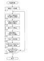
続いて、電子部品実装機1の通信装置による画像データの転送処理について、図2~図4を参照して説明する。カメラ3において通信装置を構成するCPU40は、図2に示すように、実装機制御装置2による指令に基づいて撮像を行い、当該撮像により画像データ5を取得する(S11)。ここで、本実施形態において、カメラ3により取得された画像データ5は、図3に示すように、1ラインが1024画素で構成されているものとする。また、各画素は、8ビットからなるビットデータにより輝度を256段階(256=2^8)で示されているものとする。
続いて、電子部品実装機1の通信装置による画像データの転送処理について、図2~図4を参照して説明する。カメラ3において通信装置を構成するCPU40は、図2に示すように、実装機制御装置2による指令に基づいて撮像を行い、当該撮像により画像データ5を取得する(S11)。ここで、本実施形態において、カメラ3により取得された画像データ5は、図3に示すように、1ラインが1024画素で構成されているものとする。また、各画素は、8ビットからなるビットデータにより輝度を256段階(256=2^8)で示されているものとする。
そして、通信装置は、この画像データ5に誤り検出のためのCRC値を埋め込む画像処理を行って、実装機側のCPU10に転送する。このとき、誤り検出においては、所定数量の連続した複数の画素を単位データLnとしてCRC値が算出される。つまり、単位データLnは、通信装置が誤り検出の対象とする最小単位の画素である。また、この単位データLnに含まれる画素数は、適宜設定することが可能であるが、本実施形態においては1ラインを構成する1024画素としている。
次に、CRC値算出部42は、単位データLnにおける上位ビット群ShのCRC値R(x)を、CRC多項式G(x)を用いて算出する(S12)。ここで、図3では、単位データLnにおける各画素をビットデータに展開した状態を模式的に示している。そして、単位データLnの上位ビット群Shは、各画素の上位側7ビットを連続する順番に連結した集合体であって、桁数が7168のビットデータである。一方で、単位データLnの下位ビット群Srは、各画素の最下位の1ビットを連続する順番に連結した集合体であり、桁数が1024のビットデータである。
そして、CRC値算出部42は、上位ビット群ShをCRC多項式G(x)で除算し、当該除算の剰余をCRC値R(x)として算出する。CPU40は、上位ビット群Shに算出されたCRC値R(x)を関連付けて、記憶装置50のRAM52に記憶する。続いて、差分算出部43は、単位データLnの下位ビット群Srの総和M1を算出する(S13)。この下位ビット群Srの総和M1は、下位ビット群のうち値が1である下位ビットの数量に相当する。そして、差分算出部43は、CRC値R(x)から下位ビット群Srの総和M1を減算して、差分(Δ1=R(x)-M1)を算出する(S14)。
下位ビット反転部44は、算出された差分Δ1に基づいて、下位ビット群Srから反転する下位ビットを選出する(S15)。このとき、下位ビット反転部44は、差分Δ1が正数の場合には(Δ1>0)、下位ビット群Srの総和M1がCRC値R(x)よりも小さいので(M1<R(x))、下位ビット群Srから値が0の下位ビットを差分Δ1だけ選出する。また、下位ビット反転部44は、差分Δ1が負数の場合には(Δ1<0)、下位ビット群Srの総和M1がCRC値R(x)よりも大きいので(M1>R(x))、下位ビット群Srから値が1の下位ビットを差分Δ1だけ選出する。
また、下位ビット反転部44は、下位ビット群Srから値が0または1の下位ビットを選出する際に、図4に示すように、1ラインの両端側に位置する下位ビットを優先して選出するようにしている。つまり、選出される下位ビットは、単位データLnにおける先頭側および末尾側に偏ることになる。
そして、下位ビット反転部44は、選出された1または複数の下位ビットの値を0から1に、または1から0に反転させる(S16)。これにより、下位ビット反転部44は、反転後の下位ビット群Srの総和M2がCRC値R(x)と等しくなるようにしている。このような画像処理により、反転した1または複数の下位ビットを有する画素の輝度は、1段階だけ変化することになる。しかしながら、通信装置は、一般のCRC方式のようにCRC値を冗長ビットとして付加することなく、単位データLnの下位ビット群にCRC値R(x)を埋め込んでデータサイズが変化しないようにしている。CPU40は、反転後の下位ビット群Srを記憶装置50のRAM52に記憶する。
通信部41は、カメラリンク規格に準拠した通信により、単位データLnを実装機制御装置2に転送する(S17)。より具体的には、通信部41は、RAM52に記憶されている上位ビット群Shと下位ビット群Srから、対応する上位ビットと下位ビットを合成して単位データLnを生成する。そして、通信部41は、必要に応じて単位データLnの末尾にストップビットを付加するなどして単位データLnを転送している。
通信装置は、画像データ5における全てのラインについて、実装機制御装置2への転送が終了したか否かを判定する(S18)。転送が終了していない場合には(S18:No)、画像データ5における次のラインに移行して、当該ラインにおけるCRC値R(x)の埋め込み、および実装機制御装置2への転送を実行する。このように、通信装置は、S12~S17を繰り返すことにより、画像データ5の各ラインにCRC値R(x)を埋め込み、実装機制御装置2から画像データの転送要求が継続していることを条件として、画像データ5を順次転送する。そして、画像データ5における全てのラインについて転送が終了した場合には(S18:Yes)、通信装置による画像データ5の転送処理を終了する。
(通信装置による画像データの誤り検出処理)
続いて、電子部品実装機1の通信装置による画像データの誤り検出処理について、図5を参照して説明する。実装機制御装置2において通信装置を構成するCPU10は、図5に示すように、カメラ3から伝送された画像データ5を取得する(S21)。通信装置は、上述したように、画像データ5の1ラインを構成する複数の画素を単位データLnとし、この単位データLnごとに通信における誤り検出処理を実行する。
続いて、電子部品実装機1の通信装置による画像データの誤り検出処理について、図5を参照して説明する。実装機制御装置2において通信装置を構成するCPU10は、図5に示すように、カメラ3から伝送された画像データ5を取得する(S21)。通信装置は、上述したように、画像データ5の1ラインを構成する複数の画素を単位データLnとし、この単位データLnごとに通信における誤り検出処理を実行する。
CPU10は、伝送された画像データ5における単位データLnを上位ビット群Shと下位ビット群Srに分割する。そして、制御側のCRC値算出部12は、上位ビット群ShのCRC値R(x)を、CRC多項式G(x)を用いて算出する(S22)。CRC値算出部12によるS22の処理については、カメラ3側のCRC値算出部42によるS12の処理と実質的に同一であるため、詳細な説明を省略する。また、CRC多項式G(x)は、実装機制御装置2の記憶装置20に予め記憶されているものであり、カメラ3の記憶装置50に記憶されているものと同一である。
次に、制御側の差分算出部13は、下位ビット群Srの総和M3を算出する(S23)。さらに、差分算出部13は、CRC値R(x)から下位ビット群Srの総和M3を減算して、差分(Δ2=R(x)-M3)を算出する(S24)。差分算出部13によるS23,S24の処理については、カメラ3側の差分算出部43によるS13,S14の処理と実質的に同一であるため、詳細な説明を省略する。
通信エラー検出部14は、算出された差分に基づいて通信エラーを検出する(S25)。ここで、画像データ5の通信においてノイズなどの影響がなかった場合には、S22において算出されたCRC値R(x)は、画像データ5の転送前にカメラ3側で算出されたCRC値R(x)と同値となる。同様に、S23において算出された下位ビット群Srの総和M3は、画像データ5の転送前において一部の下位ビットが反転された下位ビット群Srの総和M2と同値となる。よって、通信エラー検出部14は、S25において算出された差分が0以外、即ち総和M3と差分Δ2が不等(M3≠Δ2)であることをもって通信エラーを検出する。
続いて、通信装置は、S25で通信エラーが検出されたか否かを判定する(S26)。通信エラーが検出されなかった場合には(S26:Yes)、画像データ5における全てのラインについて、誤り検出が終了したか否かを判定する(S26)。全てのラインの誤り検出が終了していない場合には(S26:No)、画像データ5における次のラインに移行して、S22に戻る。このように、通信装置は、S22~S26を繰り返すことにより、画像データ5の各ラインに対して順次誤り検出を実行する。
通信装置は、画像データ5における全てのラインの誤り検出が終了した場合には(S27:Yes)、画像データ5の誤り検出処理を終了する。そして、実装機制御装置2は、例えば、画像処理部15が取得した画像データ5に対して、用途に応じた画像処理を実行する。また、S25で通信エラーが検出された場合には(S26:No)、通信装置は、実装機制御装置2に通信エラーが発生したことを通知し(S28)、画像データ5の誤り検出処理を中断して終了する。そして、実装機制御装置2は、例えば、カメラ3に対して撮像を行うように制御信号を送出して、再び取得した画像データを転送するようにカメラ3に要求する。
ここで、説明を簡易にするために、通信装置は、実装機制御装置2とカメラ3の通信が終了した後に、取得した画像データ5について誤り検出処理を行うものとした。これに対して、通信装置は、通信中において、制御側の通信部11が画像データ5のうち単位データLnを取得するごとに順次、その単位データLnに対して誤り検出処理を実行するようにしてもよい。このようにすることで、通信エラーの検出および対処の早期化を図ることができる。
(本実施形態の構成による効果)
上述した構成からなる通信装置は、CRC値R(x)を利用した誤り検出処理を行うが、CRC値R(x)を送信する画像データ5の下位ビット群Srに埋め込むように画像処理するものとした。つまり、通信装置は、画像データ5にCRC値R(x)を冗長ビットとして付加しないため、データサイズを変えることなく画像データ5を伝送することができる。また、画像データ5の受信側である実装機制御装置2は、下位ビット群Srの総和M3からCRC値R(x)を取得できるので、通常のCRC方式と同様の手順により、上位ビット群のCRC値R(x)と比較して誤り検出を行うことが可能である。このように、パリティ方式と比較してバースト誤りを検出可能な点で有利なCRC方式を、通信に要する時間を長くすることなく画像データの通信に適用することができる。
上述した構成からなる通信装置は、CRC値R(x)を利用した誤り検出処理を行うが、CRC値R(x)を送信する画像データ5の下位ビット群Srに埋め込むように画像処理するものとした。つまり、通信装置は、画像データ5にCRC値R(x)を冗長ビットとして付加しないため、データサイズを変えることなく画像データ5を伝送することができる。また、画像データ5の受信側である実装機制御装置2は、下位ビット群Srの総和M3からCRC値R(x)を取得できるので、通常のCRC方式と同様の手順により、上位ビット群のCRC値R(x)と比較して誤り検出を行うことが可能である。このように、パリティ方式と比較してバースト誤りを検出可能な点で有利なCRC方式を、通信に要する時間を長くすることなく画像データの通信に適用することができる。
また、本実施形態の通信装置による画像データの伝送では、下位ビット群Srの総和M1とCRC値R(x)との差分Δ1だけ下位ビットが反転されるので、画像データ5における一部の情報が変更されることになる。ここで、画像データ5は、各画素の8ビットからなるビットデータにより輝度を示されるものとした。そして、このビットデータの下位ビットが反転されたとしても、当該画素の輝度が数段階だけ変化するのみであり、画像データ5全体に対する影響は小さい。つまり、通信装置は、CRC値R(x)を下位ビット群Srに埋め込むように画像処理することで、受信側での画像データ5を使用した処理への影響を抑制している。
さらに、本実施形態においては、下位ビット反転部44により反転され得る下位ビットを、画像データ5における最下位ビットとした。これにより、下位ビット反転部44が下位ビットを反転したとしても、画素における輝度の変化を小さくすることができる。つまり、各画素のビットデータの最下位ビットが反転されたとしても、当該画素の輝度が1段階だけ変化するのみで、画像データ5全体に対する影響を最小にできる。よって、通信装置は、受信側での画像データ5を使用した処理への影響を最小限に抑えることができる。
通信装置は、誤り検出の最小単位である単位データLnを、画像データ5における1ラインを構成する複数の画素とした。これにより、通信装置は、単位データLnに対してCRC値R(x)を算出して、このCRC値R(x)を下位ビット群Srに埋め込むように画像処理する。そのため、受信側である実装機制御装置2は、伝送された画像データ5における1ライン分のデータ数に基づいて、CRC方式の誤り検出を行うことができる。このように、通信装置は、画像データ5に区切り記号などを付加することなく誤り検出の処理が可能となるため、画像処理を効率的に行うことができる。
また、下位ビット反転部44は、反転する下位ビットを選出する際に、1ラインの両端側に位置する下位ビットを優先して選出するものとした。これにより、下位ビット反転部44により反転する下位ビットは、1ラインの両端側に偏ることになる。通信装置は、下位ビット群SrにCRC値R(x)を埋め込むように画像処理するため、CRC値R(x)と下位ビット群Srの総和M1の差分Δ1が0でない限り、画像データ5における一部の情報は少なからず変更される。しかしながら、実装機制御装置2の画像処理部15においては、被写体が画像データ5の中央にあるなど、画像データ5で必要される領域が中央部のみで足りることもある。このような場合には、下位ビット反転部44により反転される下位ビットを1ラインの両端側に偏らせることにより、画像処理部15による処理への影響をさらに抑制することができる。
通信装置を構成するカメラ3の通信部41および実装機制御装置2の通信部11は、カメラリンク規格に準拠した通信を行うものとした。本実施形態の通信装置では、CRC値R(x)が下位ビット群Srに埋め込まれることから、画像データ5におけるCRC値R(x)の場所を特定する所定のコマンドの付加などが不要であり、CRC方式による誤り検出を好適に適用できる。つまり、例示した誤り検出処理は、伝送されるデータが可変長となるカメラリンク規格であっても、バースト誤りの検出などに有効なCRC値R(x)を利用した誤り検出を行うことができるので、特に有用である。
電子部品実装機1は、実装機制御装置2の通信エラー検出部14により通信エラーを検出できるので、伝送された画像データ5における誤りの有無を検証することができる。よって、電子部品実装機1は、誤りのある画像データ5に基づいて電子部品の実装が制御されることを防止できる。これにより、制御装置が撮像装置に対して撮像の実行および画像データ5の伝送を再度要求することで、誤りのない画像データ5を用いた制御が可能となり、電子部品実装機1の実装の精度を向上させることができる。
<第二実施形態>
第二実施形態の通信装置および電子部品実装機101について、図6~図8を参照して説明する。本実施形態の通信装置は、主として、第一実施形態とCRC値R(x)の埋め込み処理が相違する。その他の共通する構成については、第一実施形態と実質的に同一であるため、詳細な説明を省略する。以下、相違点のみについて説明する。
第二実施形態の通信装置および電子部品実装機101について、図6~図8を参照して説明する。本実施形態の通信装置は、主として、第一実施形態とCRC値R(x)の埋め込み処理が相違する。その他の共通する構成については、第一実施形態と実質的に同一であるため、詳細な説明を省略する。以下、相違点のみについて説明する。
(CRC値と画像処理について)
ここで、通信装置は、CRC値R(x)を利用して通信の誤り検出処理を行う機能を有する。そして、上述したように、このCRC値R(x)は、画像データ5のデータサイズが変化しないように、画像データ5の一部(下位ビット群Sr)に埋め込まれるものとした。そのため、第一実施形態で例示した画像処理では、単位データLnにより表現可能な範囲を超えたCRC値R(x)を、下位ビット群Srに埋め込むことができないことがある。
ここで、通信装置は、CRC値R(x)を利用して通信の誤り検出処理を行う機能を有する。そして、上述したように、このCRC値R(x)は、画像データ5のデータサイズが変化しないように、画像データ5の一部(下位ビット群Sr)に埋め込まれるものとした。そのため、第一実施形態で例示した画像処理では、単位データLnにより表現可能な範囲を超えたCRC値R(x)を、下位ビット群Srに埋め込むことができないことがある。
より具体的には、第一実施形態のように、単位データLnを画像データ5における1ラインとし、且つ下位ビットを各画素のビットデータの最下位ビットとすると、画像データ5における1ラインが1024画素であれば、単位データLnにより表現可能な範囲は、0~1024となる。つまり、CRC値R(x)が1024を超える場合には、即ち二進法で示されるCRC値R(x)の桁数が10桁を超える場合には、下位ビット群SrにCRC値R(x)を埋め込むことができない。
一方で、CRC方式による誤り検出では、検出精度を向上させるためにCRC多項式G(x)の次数を増加させることが知られている。また、8ビットデータの通信には、ビット長さが17ビットのCRC多項式G(x)が用いられることがある。そのため、算出されるCRC値R(x)を二進法で示した場合には、その桁数が16桁を取り得ることになり、単位データLnにより表現可能な範囲を超えてしまう。
また、単位データLnにより表現可能な範囲を大きくするために、下位ビットを各画素のビットデータの下位側から複数ビットに設定したり、単位データLnに含む画素数を増加させたりすることが考えられる。しかし、前者の場合には、下位ビットの反転に伴う影響も大きくなってしまう。また、後者の場合には、単位データLnのデータサイズが大きくなり、転送前におけるCRC値R(x)の埋め込み処理の負荷が大きくなるおそれがある。
そこで、本実施形態では、単位データLnのデータサイズを増やすことなく、桁数の増大させたCRC値R(x)に対応した誤り検出処理について説明する。ここで、以下の説明では、カメラ3により取得された画像データ5は、1ラインが1024画素で構成されているものとする。また、通信装置が対象とする誤り検出の単位データLnは、画像データ5の1ラインを構成する1024画素により構成されているものとする。さらに、CRC多項式G(x)は、そのビット長が33ビットに設定されているものとする。
(通信装置の構成)
本実施形態において、通信装置は、図6に示すように、実装機制御装置2のCPU100と、カメラ3のCPU140と、通信ケーブル4とを備えて構成される。画像データ5の通信における送信側となるカメラ3のCPU140は、通信部41と、CRC値算出部42と、差分算出部143と、下位ビット反転部44とを有する。ここで、通信部41およびCRC値算出部42は、第一実施形態と同一の構成であるため、詳細な説明を省略する。差分算出部143は、CRC値R(x)および下位ビット群Srを分割する分割部143aと、分割されたセットごとに差分を算出するセット差分算出部143bとを有する。
本実施形態において、通信装置は、図6に示すように、実装機制御装置2のCPU100と、カメラ3のCPU140と、通信ケーブル4とを備えて構成される。画像データ5の通信における送信側となるカメラ3のCPU140は、通信部41と、CRC値算出部42と、差分算出部143と、下位ビット反転部44とを有する。ここで、通信部41およびCRC値算出部42は、第一実施形態と同一の構成であるため、詳細な説明を省略する。差分算出部143は、CRC値R(x)および下位ビット群Srを分割する分割部143aと、分割されたセットごとに差分を算出するセット差分算出部143bとを有する。
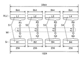
分割部143aは、二進法で示されるCRC値R(x)を所定の分割数Pで複数のビット列L1~L4に分割する。ここで、CRC値算出部42により算出されたCRC値R(x)は、CRC多項式G(x)のビット長が33ビットであることから、二進法で示された場合には桁数が32桁となる。また、本実施形態において、分割数Pは、4に設定されている(分割数Pの設定方法については後述する)。つまり、32桁のCRC値R(x)は、図7に示すように、上位側から各8ビットのビット列L1~L4に分割される。ここで、各ビット列L1~L4により示される8桁の部分的なCRC値を、サブCRC値R1~R4とする。
また、分割部143aは、下位ビット群Srを、各ビット列L1~L4に対応させて分割数Pで複数のブロックB1~B4に分割する。つまり、1024画素の最下位ビットからなる下位ビット群Srは、上位側から256個ずつの下位ビットにより構成されるブロックB1~B4に分割される。ここで、32桁のCRC値R(x)は、十進数で示した場合には、{0~(2^32)}の範囲の値を取り得る。しかし、各ビット列L1~L4がそれぞれ8ビットからなるため、サブCRC値R1~R4は、取り得る値の範囲が{0~(2^8)}となる。よって、各ブロックB1~B4は、(256=2^8)個の下位ビットを有することから、対応する各ビット列L1~L4により示されるサブCRC値R1~R4の取り得る値の範囲を表現可能となる。
セット差分算出部134bは、ブロックB1~B4に含まれる各下位ビットの小計N1~N4を算出する。この小計N1~N4は、各ブロックB1~B4において値が1である下位ビットの数量に相当する。また、セット差分算出部134bは、小計N1~N4とCRC値R1~R4との差分δ1~δ4を、対応するビット列L1~L4とブロックB1~B4のセットS1~S4ごとに算出する(δ1=R1-N1、δ2~δ4も同様)。
続いて、下位ビット反転部44は、セットS1のブロックB1から、セット差分算出部134bによりセットS1に対して算出された差分δ1だけ下位ビットを選出する。このとき、下位ビット反転部44により選出される下位ビットは、差分δ1が正数の場合(R1>N1)には値が0のものであり、差分δ1が負数の場合(R1<N1)には値が1のものである。また、下位ビット反転部44は、ブロックB1から値が0または1の下位ビットを選出する際に、図8に示すように、等間隔となるように複数の下位ビットを選出する。つまり、下位ビット反転部44は、選出される複数の下位ビットがブロック1内において、なるべく分散するように選出する。
そして、下位ビット反転部44は、選出された1または複数の下位ビットの値を0から1に、または1から0に反転させる。下位ビット反転部44は、他のセットS2~S4についても同様に、差分δ2~δ4だけ下位ビットを各ブロックB2~B4から選出するとともに値を反転させる。これにより、反転後の各ブロックB1~B4の小計N1'~N4'は、サブCRC値R1~R4とそれぞれ等しくなる。このように、下位ビット反転部44は、反転後の下位ビット群Srの総和M2{M2=(N1'+N2'+N3'+N4')}を、CRC値R(x){R(x)=(R1,R2,R3,R4)}と等しくしている。
画像データ5の通信における受信側となる実装機制御装置2のCPU110は、通信部11と、CRC値算出部12と、差分算出部113と、通信エラー検出部14と、画像処理部15とを有する。ここで、実装機制御装置2の差分算出部113は、分割部113aと、セット差分算出部113bとを有し、カメラ3の差分算出部143と実質的に同一の処理を行うものである。よって、差分算出部113の詳細な説明を省略する。
また、通信エラー検出部14は、実装機制御装置2における差分算出部113のセット差分算出部113bにより算出された差分δ1'~δ4'に基づいて通信エラーを検出する。より具体的には、通信エラー検出部14は、差分δ1'~δ4'のうち何れかが0以外である場合に、画像データ5の通信においてノイズなどの影響があったものとして通信エラーを検出する。一方で、何れの差分δ1'~δ4'も0である場合には、下位ビット群Srの総和M3がCRC値R(x)と等しい{M3=(R1,R2,R3,R4)}。従って、通信装置は、このような場合には、正常に通信が行われたものと判定することができる。
このように、通信装置は、単位データLnのデータサイズを増やすことなく、桁数が32桁のCRC値R(x)を画像データ5に埋め込む画像処理、およびこのCRC値R(x)を利用した誤り検出処理を可能としている。これは、分割部143a,113aにより、適正な分割数PでCRC値R(x)および下位ビット群Srを分割したことによるものである。ここで、分割数Pは、CRC値R(x)の桁数、単位データLnのデータサイズ、および下位ビットのビット数を勘案して設定される必要がある。
ここで、分割部143a,113aにより分割されるCRC値R(x)および下位ビット群Srの分割数Pは、本実施形態において、4に設定されるものとした(P=4)。この分割数Pは、ブロックB1に含まれる下位ビットの数量T1がビット列L1の桁数U1だけ2を累乗した値以上(T1≧2^U1)となるように設定されている。
より具体的には、ブロックB1に含まれる下位ビットの数量T1は、単位データLnが1024画素であり、下位ビットが最下位ビットのみであることから、T1=1024/Pで表される。また、ビット列L1の桁数U1は、CRC値R(x)が32桁であることから、U1=32/Pで表される。よって、分割数Pは、上記の条件{1024/P≧2^(32/P)}を満たすことから、P≧4の整数に設定される。また、分割数Pは、他のセットS2~S4においても同様の条件を満たすように設定される。
(本実施形態の構成による効果)
上述した構成からなる通信装置は、CRC値R(x)および下位ビット群Srをそれぞれ分割し、各ブロックB1~B4の下位ビットを各ビット列L1~L4に対応して反転させるものとした。これにより、通信装置は、CRC多項式G(x)の次数を増加させた場合においても、当該CRC多項式G(x)を用いて算出されたCRC値R(x)を下位ビット群Srに埋め込むように画像処理することができる。よって、CRC値R(x)を利用した誤り検出における精度を向上できる。
上述した構成からなる通信装置は、CRC値R(x)および下位ビット群Srをそれぞれ分割し、各ブロックB1~B4の下位ビットを各ビット列L1~L4に対応して反転させるものとした。これにより、通信装置は、CRC多項式G(x)の次数を増加させた場合においても、当該CRC多項式G(x)を用いて算出されたCRC値R(x)を下位ビット群Srに埋め込むように画像処理することができる。よって、CRC値R(x)を利用した誤り検出における精度を向上できる。
また、下位ビット反転部44は、各ブロックB1~B4から反転させる下位ビットを選出する際に、ブロックB1~B4内において選出された下位ビット同士が等間隔となるように選出するものとした。これにより、下位ビット反転部44により反転される下位ビットは、下位ビット群Srにおいて分散することになる。よって、連続する下位ビットが共に反転されることを抑制できるので、反転による画像データ5への影響を抑制することができる。
<第一、第二実施形態の変形態様>
実施形態(第一、第二実施形態)において、下位ビットは、画像データ5の各画素における最下位ビットとした。これに対して、下位ビットは、各画素のビットデータの下位側から複数ビットに設定してもよい。これにより、下位ビット群のビット数が増加するため、下位ビット群が表現可能な範囲を大きくして、桁数を増やしたCRC値R(x)に対応することができる。但し、下位ビットの反転による画像データ5への影響を抑制するという観点からは、実施形態で例示したように、下位ビットを各画素における最下位ビットに設定することが好ましい。
実施形態(第一、第二実施形態)において、下位ビットは、画像データ5の各画素における最下位ビットとした。これに対して、下位ビットは、各画素のビットデータの下位側から複数ビットに設定してもよい。これにより、下位ビット群のビット数が増加するため、下位ビット群が表現可能な範囲を大きくして、桁数を増やしたCRC値R(x)に対応することができる。但し、下位ビットの反転による画像データ5への影響を抑制するという観点からは、実施形態で例示したように、下位ビットを各画素における最下位ビットに設定することが好ましい。
また、通信装置が対象とする誤り検出の最小単位である単位データLnは、画像データ5における1ラインを構成するものとした。これに対して、単位データLnは、連続した複数の画素であればよく、1ライン未満の画素、複数ラインを含む画素、または画像データ5に含まれる全ての画素としてもよい。通信装置は、画像データ5の1ラインの画素数や処理負荷などを勘案して、単位データLnのデータサイズを適宜設定してもよい。
通信装置は、カメラリンク規格に準拠した通信を行うものとした。本実施形態で例示した誤り検出処理は、伝送されるデータが可変長となるカメラリンク規格に対応し、CRC値R(x)を利用して高精度に通信エラーを検出できるので特に有用である。しかし、当該誤り検出処理は、パケット通信など、その他の通信規格に準拠した通信にも適用することができる。このような場合においても、伝送する画像データ5のデータサイズを付加することなくCRC値R(x)を利用した誤り検出処理が可能である。よって、通信に要する時間を増加することなく、通信エラーを高精度に検出することができる。
本実施形態では、通信装置は、電子部品実装機1,101に適用され、カメラ3から実装機制御装置2への画像データ5の伝送における誤り検出処理を行う構成を例示して説明した。これに対して、通信装置は、実装機制御装置2やカメラ3以外に、種々の装置や集積回路との間に用いられる通信を行う構成にも適用することが可能である。
1,101:電子部品実装機
2:実装機制御装置
10,110:CPU(通信装置)
11:通信部、 12:CRC値算出部
13,113:差分算出部
113a:分割部、 113b:セット差分算出部
14:通信エラー検出部、 15:画像処理部
20:記憶装置
3:カメラ(撮像装置)
30:光学ユニット、 31:レンズ部、 32:撮像素子
40,140:CPU(通信装置)
41:通信部、 42:CRC値算出部
43,143:差分算出部
143a:分割部、 143b:セット差分算出部
44:下位ビット反転部
50:記憶装置、 51:ROM、 52:RAM
4:通信ケーブル
5:画像データ
G(x):CRC多項式、 R(x):CRC値
L1~L4:ビット列、 R1~R4:サブCRC値
Ln:単位データ、 Sh:上位ビット群、 Sr:下位ビット群
M1~M3:下位ビット群の総和
B1~B4:ブロック、 N1~N4,N1'~N4':小計
Δ1,Δ2:差分、 δ1~δ4,δ1'~δ4':セットの差分
S1~S4:セット、 P:分割数
T1:ブロックB1の下位ビットの数量、 U1:ビット列L1の桁数
2:実装機制御装置
10,110:CPU(通信装置)
11:通信部、 12:CRC値算出部
13,113:差分算出部
113a:分割部、 113b:セット差分算出部
14:通信エラー検出部、 15:画像処理部
20:記憶装置
3:カメラ(撮像装置)
30:光学ユニット、 31:レンズ部、 32:撮像素子
40,140:CPU(通信装置)
41:通信部、 42:CRC値算出部
43,143:差分算出部
143a:分割部、 143b:セット差分算出部
44:下位ビット反転部
50:記憶装置、 51:ROM、 52:RAM
4:通信ケーブル
5:画像データ
G(x):CRC多項式、 R(x):CRC値
L1~L4:ビット列、 R1~R4:サブCRC値
Ln:単位データ、 Sh:上位ビット群、 Sr:下位ビット群
M1~M3:下位ビット群の総和
B1~B4:ブロック、 N1~N4,N1'~N4':小計
Δ1,Δ2:差分、 δ1~δ4,δ1'~δ4':セットの差分
S1~S4:セット、 P:分割数
T1:ブロックB1の下位ビットの数量、 U1:ビット列L1の桁数
Claims (8)
- 画像データを対象とした通信を行う通信装置であって、
前記画像データのうち連続する複数の画素を単位データとし、前記単位データにおける各上位ビットにより構成される上位ビット群のCRC値を、予め設定されているCRC多項式を用いて算出するCRC値算出部と、
前記単位データにおける各下位ビットにより構成される下位ビット群の総和と前記CRC値との差分を算出する差分算出部と、
前記下位ビット群から前記差分だけ選出した1または複数の前記下位ビットを反転させて、反転後における前記下位ビットの総和を前記CRC値と等しくする下位ビット反転部と、
を備える通信装置。 - 請求項1において、
前記下位ビットは、前記画素における最下位ビットである通信装置。 - 請求項1または2において、
前記単位データは、前記画像データにおける1ラインを構成する通信装置。 - 請求項3において、
前記下位ビット反転部は、1ラインの両端側に位置する前記下位ビットを優先して選出して反転させる通信装置。 - 請求項1~3において、
前記下位ビット反転部は、複数の前記下位ビットから等間隔となるように複数の前記下位ビットを選出して反転する通信装置。 - 請求項1~5の何れか一項において、
前記差分算出部は、
二進法で示される前記CRC値を複数のビット列に分割するとともに、前記下位ビット群を各前記ビット列に対応させて複数のブロックに分割する分割部と、
前記ブロックに含まれる各前記下位ビットの小計と、前記ビット列により示されるサブCRC値との差分を、対応する前記ビット列と前記ブロックのセットごとに算出するセット差分算出部と、を有し、
前記下位ビット反転部は、前記セットの前記ブロックから当該セットに対して算出された前記差分だけ選出した1または複数の前記下位ビットを反転させて、反転後における前記下位ビットの前記小計を前記サブCRC値と等しくすることにより、前記下位ビット群の総和を前記CRC値と等しくし、
前記分割部により分割される前記CRC値および前記下位ビット群の分割数は、前記ブロックに含まれる前記下位ビットの数量が前記ビット列の桁数だけ2を累乗した値以上となるように設定されている通信装置。 - 請求項1~6の何れか一項において、
カメラリンク規格に準拠した通信を行う通信部をさらに備える通信装置。 - 請求項1~7の何れか一項の通信装置を有し、被写体を撮像して画像データを記録する撮像装置と、
前記撮像装置の前記通信装置と通信可能に接続され、前記通信装置から送出された前記画像データを取得し、当該画像データと予め記憶している制御プログラムに基づいて電子部品の実装を制御する制御装置と、
を備える電子部品実装機において、
前記制御装置は、
取得した前記画像データのうち前記単位データにおける前記上位ビット群のCRC値を、前記CRC多項式を用いて算出する制御側CRC値算出部と、
前記単位データにおける前記下位ビット群の総和と前記CRC値との差分を算出する制御側差分算出部と、
算出された前記差分に基づいて通信エラーを検出する通信エラー検出部と、
を有する電子部品実装機。
Priority Applications (2)
| Application Number | Priority Date | Filing Date | Title |
|---|---|---|---|
| JP2014537965A JP5995982B2 (ja) | 2012-09-27 | 2012-09-27 | 通信装置および電子部品実装機 |
| PCT/JP2012/074985 WO2014049796A1 (ja) | 2012-09-27 | 2012-09-27 | 通信装置および電子部品実装機 |
Applications Claiming Priority (1)
| Application Number | Priority Date | Filing Date | Title |
|---|---|---|---|
| PCT/JP2012/074985 WO2014049796A1 (ja) | 2012-09-27 | 2012-09-27 | 通信装置および電子部品実装機 |
Publications (1)
| Publication Number | Publication Date |
|---|---|
| WO2014049796A1 true WO2014049796A1 (ja) | 2014-04-03 |
Family
ID=50387259
Family Applications (1)
| Application Number | Title | Priority Date | Filing Date |
|---|---|---|---|
| PCT/JP2012/074985 Ceased WO2014049796A1 (ja) | 2012-09-27 | 2012-09-27 | 通信装置および電子部品実装機 |
Country Status (2)
| Country | Link |
|---|---|
| JP (1) | JP5995982B2 (ja) |
| WO (1) | WO2014049796A1 (ja) |
Cited By (2)
| Publication number | Priority date | Publication date | Assignee | Title |
|---|---|---|---|---|
| JPWO2023187923A1 (ja) * | 2022-03-28 | 2023-10-05 | ||
| US12014550B1 (en) * | 2021-03-26 | 2024-06-18 | Zoox, Inc. | Image data protection using data integrity checks |
Citations (2)
| Publication number | Priority date | Publication date | Assignee | Title |
|---|---|---|---|---|
| JP2005198158A (ja) * | 2004-01-09 | 2005-07-21 | Hitachi Kokusai Electric Inc | 画像改ざん検出システム |
| JP2009005146A (ja) * | 2007-06-22 | 2009-01-08 | Panasonic Corp | データ伝送装置 |
Family Cites Families (1)
| Publication number | Priority date | Publication date | Assignee | Title |
|---|---|---|---|---|
| US20100138724A1 (en) * | 2008-12-01 | 2010-06-03 | Dsp Group Ltd. | Adaptive error protection for wireless communications |
-
2012
- 2012-09-27 WO PCT/JP2012/074985 patent/WO2014049796A1/ja not_active Ceased
- 2012-09-27 JP JP2014537965A patent/JP5995982B2/ja active Active
Patent Citations (2)
| Publication number | Priority date | Publication date | Assignee | Title |
|---|---|---|---|---|
| JP2005198158A (ja) * | 2004-01-09 | 2005-07-21 | Hitachi Kokusai Electric Inc | 画像改ざん検出システム |
| JP2009005146A (ja) * | 2007-06-22 | 2009-01-08 | Panasonic Corp | データ伝送装置 |
Cited By (4)
| Publication number | Priority date | Publication date | Assignee | Title |
|---|---|---|---|---|
| US12014550B1 (en) * | 2021-03-26 | 2024-06-18 | Zoox, Inc. | Image data protection using data integrity checks |
| JPWO2023187923A1 (ja) * | 2022-03-28 | 2023-10-05 | ||
| WO2023187923A1 (ja) * | 2022-03-28 | 2023-10-05 | 株式会社Fuji | 画像データ送受信システム、画像データ送受信方法、部品実装機 |
| JP7812913B2 (ja) | 2022-03-28 | 2026-02-10 | 株式会社Fuji | 画像データ送受信システム、画像データ送受信方法、部品実装機 |
Also Published As
| Publication number | Publication date |
|---|---|
| JPWO2014049796A1 (ja) | 2016-08-22 |
| JP5995982B2 (ja) | 2016-09-21 |
Similar Documents
| Publication | Publication Date | Title |
|---|---|---|
| CN202889529U (zh) | 图像输出装置、图像处理装置和成像装置 | |
| JP2012105188A (ja) | 画像出力装置、画像出力方法、画像処理装置、画像処理方法、プログラム、および撮像装置 | |
| JP4388909B2 (ja) | 画素欠陥補正装置 | |
| JP7562540B2 (ja) | 符号化装置、符号化方法、復号装置、復号方法、およびプログラム | |
| JP4559126B2 (ja) | 映像送信方法、映像送信装置、映像送信用プログラム及びそのプログラムを記録したコンピュータ読み取り可能な記録媒体 | |
| US8429505B2 (en) | Error-correction data generation apparatus and generation method | |
| CN111432112A (zh) | 处理图像信号的方法、图像信号处理器和图像传感器芯片 | |
| JP7604377B2 (ja) | 符号化装置、符号化方法、復号装置、復号方法、およびプログラム | |
| US12294391B2 (en) | Encoding device, encoding method, decoding device, decoding method, and program | |
| JP5995982B2 (ja) | 通信装置および電子部品実装機 | |
| US9634799B2 (en) | Decoding device, information transmission system, and non-transitory computer readable medium | |
| KR102510034B1 (ko) | 송신 스트림에서 에러 정정 코드들을 전송하는 방법 및 송신 스트림으로부터 데이터 스트림을 추출하는 방법 | |
| CN107072515A (zh) | 图像数据传输系统 | |
| KR100947178B1 (ko) | 카메라 시리얼 통신 인터페이스와 디스플레이 시리얼 통신인터페이스의 통합구조를 가지는 인터페이스 통합 장치 | |
| WO2021100602A1 (ja) | 送信装置、受信装置、および伝送システム | |
| JPWO2014016928A1 (ja) | 撮像装置および電子部品実装機 | |
| JP7550785B2 (ja) | 送信装置、および伝送システム | |
| CN113170029B (zh) | 图像处理装置和图像处理方法 | |
| JP7428546B2 (ja) | 撮像装置および撮像方法 | |
| JP2005210164A (ja) | 欠陥画素補正装置 | |
| JP2006074075A (ja) | 差動シリアル・ディジタル出力a/d変換手段および撮像装置 | |
| JP2012100166A (ja) | 信号処理装置 | |
| JP6199690B2 (ja) | 画像処理システム及び作業用ロボット | |
| JPWO2014136178A1 (ja) | データベース、データベースの構築方法、通信装置及び電子部品装着装置 | |
| WO2015063930A1 (ja) | 延長装置及び作業用ロボット |
Legal Events
| Date | Code | Title | Description |
|---|---|---|---|
| 121 | Ep: the epo has been informed by wipo that ep was designated in this application |
Ref document number: 12885659 Country of ref document: EP Kind code of ref document: A1 |
|
| ENP | Entry into the national phase |
Ref document number: 2014537965 Country of ref document: JP Kind code of ref document: A |
|
| NENP | Non-entry into the national phase |
Ref country code: DE |
|
| 122 | Ep: pct application non-entry in european phase |
Ref document number: 12885659 Country of ref document: EP Kind code of ref document: A1 |