WO2014049657A1 - Medical-use pump - Google Patents
Medical-use pump Download PDFInfo
- Publication number
- WO2014049657A1 WO2014049657A1 PCT/JP2012/006213 JP2012006213W WO2014049657A1 WO 2014049657 A1 WO2014049657 A1 WO 2014049657A1 JP 2012006213 W JP2012006213 W JP 2012006213W WO 2014049657 A1 WO2014049657 A1 WO 2014049657A1
- Authority
- WO
- WIPO (PCT)
- Prior art keywords
- infusion tube
- occlusion
- infusion
- needle
- medical pump
- Prior art date
Links
Images


Classifications
-
- A—HUMAN NECESSITIES
- A61—MEDICAL OR VETERINARY SCIENCE; HYGIENE
- A61M—DEVICES FOR INTRODUCING MEDIA INTO, OR ONTO, THE BODY; DEVICES FOR TRANSDUCING BODY MEDIA OR FOR TAKING MEDIA FROM THE BODY; DEVICES FOR PRODUCING OR ENDING SLEEP OR STUPOR
- A61M5/00—Devices for bringing media into the body in a subcutaneous, intra-vascular or intramuscular way; Accessories therefor, e.g. filling or cleaning devices, arm-rests
- A61M5/14—Infusion devices, e.g. infusing by gravity; Blood infusion; Accessories therefor
- A61M5/142—Pressure infusion, e.g. using pumps
- A61M5/14212—Pumping with an aspiration and an expulsion action
- A61M5/14228—Pumping with an aspiration and an expulsion action with linear peristaltic action, i.e. comprising at least three pressurising members or a helical member
-
- A—HUMAN NECESSITIES
- A61—MEDICAL OR VETERINARY SCIENCE; HYGIENE
- A61M—DEVICES FOR INTRODUCING MEDIA INTO, OR ONTO, THE BODY; DEVICES FOR TRANSDUCING BODY MEDIA OR FOR TAKING MEDIA FROM THE BODY; DEVICES FOR PRODUCING OR ENDING SLEEP OR STUPOR
- A61M5/00—Devices for bringing media into the body in a subcutaneous, intra-vascular or intramuscular way; Accessories therefor, e.g. filling or cleaning devices, arm-rests
- A61M5/14—Infusion devices, e.g. infusing by gravity; Blood infusion; Accessories therefor
- A61M5/158—Needles for infusions; Accessories therefor, e.g. for inserting infusion needles, or for holding them on the body
- A61M2005/1588—Needles for infusions; Accessories therefor, e.g. for inserting infusion needles, or for holding them on the body having means for monitoring, controlling or visual inspection, e.g. for patency check, avoiding extravasation
-
- A—HUMAN NECESSITIES
- A61—MEDICAL OR VETERINARY SCIENCE; HYGIENE
- A61M—DEVICES FOR INTRODUCING MEDIA INTO, OR ONTO, THE BODY; DEVICES FOR TRANSDUCING BODY MEDIA OR FOR TAKING MEDIA FROM THE BODY; DEVICES FOR PRODUCING OR ENDING SLEEP OR STUPOR
- A61M5/00—Devices for bringing media into the body in a subcutaneous, intra-vascular or intramuscular way; Accessories therefor, e.g. filling or cleaning devices, arm-rests
- A61M5/14—Infusion devices, e.g. infusing by gravity; Blood infusion; Accessories therefor
- A61M5/168—Means for controlling media flow to the body or for metering media to the body, e.g. drip meters, counters ; Monitoring media flow to the body
- A61M5/16831—Monitoring, detecting, signalling or eliminating infusion flow anomalies
- A61M2005/16863—Occlusion detection
- A61M2005/16868—Downstream occlusion sensors
-
- A—HUMAN NECESSITIES
- A61—MEDICAL OR VETERINARY SCIENCE; HYGIENE
- A61M—DEVICES FOR INTRODUCING MEDIA INTO, OR ONTO, THE BODY; DEVICES FOR TRANSDUCING BODY MEDIA OR FOR TAKING MEDIA FROM THE BODY; DEVICES FOR PRODUCING OR ENDING SLEEP OR STUPOR
- A61M5/00—Devices for bringing media into the body in a subcutaneous, intra-vascular or intramuscular way; Accessories therefor, e.g. filling or cleaning devices, arm-rests
- A61M5/14—Infusion devices, e.g. infusing by gravity; Blood infusion; Accessories therefor
- A61M5/142—Pressure infusion, e.g. using pumps
- A61M5/14212—Pumping with an aspiration and an expulsion action
- A61M5/14232—Roller pumps
-
- A—HUMAN NECESSITIES
- A61—MEDICAL OR VETERINARY SCIENCE; HYGIENE
- A61M—DEVICES FOR INTRODUCING MEDIA INTO, OR ONTO, THE BODY; DEVICES FOR TRANSDUCING BODY MEDIA OR FOR TAKING MEDIA FROM THE BODY; DEVICES FOR PRODUCING OR ENDING SLEEP OR STUPOR
- A61M5/00—Devices for bringing media into the body in a subcutaneous, intra-vascular or intramuscular way; Accessories therefor, e.g. filling or cleaning devices, arm-rests
- A61M5/36—Devices for bringing media into the body in a subcutaneous, intra-vascular or intramuscular way; Accessories therefor, e.g. filling or cleaning devices, arm-rests with means for eliminating or preventing injection or infusion of air into body
- A61M5/365—Air detectors
Definitions
- the present invention relates to a medical pump, particularly an infusion pump, for delivering a drug to a patient.
- an infusion pump is used, for example, in an intensive care unit (ICU) or the like, and is used to perform a liquid feeding treatment for a patient for a relatively long time with relatively high accuracy.
- a predetermined drug bag (infusion bag) is arranged on the infusion pump, and an infusion tube lowered from the drug bag is sandwiched between the main body and the door, and the infusion tube is accommodated in the main body.
- the door is held by closing the door.
- the outer peripheral surface of the infusion tube set at a fixed position is sandwiched between a plurality of fingers in the main body and the inner surface of the door.
- This infusion pump is a peristaltic infusion pump in which a plurality of fingers are sequentially pressed along the length of the outer peripheral surface of an infusion tube to deliver a drug to a patient through an indwelling needle (see Patent Document 1). reference).
- the infusion tube is held vertically through the infusion pump main body from top to bottom.
- an infusion pump that holds an infusion tube in a horizontal direction in the body of the infusion pump has been proposed.
- the infusion pump has a structure in which the infusion tube is held in the horizontal direction in the main body of the infusion pump so that the infusion tube passes vertically through the main body of the infusion pump from top to bottom. This is because the infusion tube does not get in the way even if a plurality of infusion pumps are stacked and held in a stacked state in the vertical position.
- the upstream side of the infusion tube is disposed on the right side of the infusion pump main body, and the downstream side of the infusion tube is disposed on the left side of the infusion pump main body.
- the drug is directed from the upstream side to the downstream side.
- Liquid can be fed along a predetermined liquid feeding direction, and liquid can be fed correctly to the patient.
- the needle tip of the indwelling needle is inserted into the blood vessel,
- the needle tip of the indwelling needle comes out of the blood vessel and stays in the tissue under the skin due to some cause, such as the patient moving, or the needle tip of the indwelling needle is left inside the blood vessel.
- the drug is delivered into the tissue while the tip of the indwelling needle is detached from the blood vessel and stays in the tissue under the skin, the affected tissue may be necrotic depending on the type of the drug. is there. Alternatively, depending on the type of drug, there is a risk of inflammation even if the tissue is not necrotic.
- an object of this invention is to provide the medical pump which can detect that the front-end
- the medical pump of the present invention is a medical pump for injecting a drug by indwelling a distal opening of an indwelling catheter or indwelling needle communicating with an infusion tube in a patient's vein, A drive motor for feeding the liquid through the infusion tube and the catheter or indwelling needle in the blood vessel, an occlusion sensor for detecting the occlusion pressure of the infusion tube when delivering the drug, and a downstream side in the medical pump
- the occlusion pressure suddenly rises above a threshold due to the occlusion pressure of the infusion tube obtained from the occlusion sensor provided in the vessel, the tip of the indwelling catheter or indwelling needle is detached from the inside of the blood vessel, and the inside of the subcutaneous tissue.
- the catheter for indwelling in the blood vessel is determined.
- the tip of the indwelling needle characterized in that it comprises a control unit which determines that the outside of the skin off from the vessel.
- the controller does not stop the operation of the drive motor even when the controller determines a sudden increase in the block pressure or when the controller determines a sudden decrease in the block pressure.
- the liquid feeding operation of the medicine is continued. According to the above configuration, since the liquid supply of the medicine is continued without immediately stopping the operation of the drive motor, after the medical worker confirms the state of the needle, the liquid supply of the medicine is made at the judgment of the medical worker. The operation can be stopped.
- warning means is further provided, wherein the warning means is at least one of a display unit that displays warning contents, a speaker that warns the warning contents by voice, and a buzzer that issues a warning.
- the medical worker can notify reliably needle
- the warning means is arranged in the medical pump and a terminal arranged in a nurse center. According to the above configuration, not only the medical staff around the medical pump but also the medical staff packed in the nurse center can be surely warned. Can be stopped.
- the display unit and an operation panel unit having operation buttons are arranged on an upper part of the main body of the medical pump, and a lower part of the main body of the medical pump is used for feeding the medicine. It is a region where a liquid feeding member is arranged.
- the medical worker can perform the liquid feeding operation
- the present invention can provide a medical pump that can reliably detect a warning to a medical worker by detecting that the tip of the needle is detached from the blood vessel (needle removal).
- FIG. 5 is a block diagram showing a part of the electrical configuration example of the infusion pump shown in FIG. 4 in more detail.
- the disassembled perspective view which shows the structural example of an upstream obstruction
- the flowchart which shows the example of monitoring in case occlusion pressure rises rapidly.
- FIG. 1 is a perspective view showing an infusion pump which is a preferred embodiment of the medical pump of the present invention.
- FIG. 2 is a view of the infusion pump shown in FIG. 1 as viewed from the W direction.
- the infusion pump 1 shown in FIGS. 1 and 2 is an example of a medical pump. As shown in FIG. 2, the infusion pump 1 is provided in the blood vessel of the patient P from the medicine bag 170 filled with the medicine 171 via the clamp 179, the infusion tube 200, and the needle (indwelling needle or catheter for intravascular placement) 172. The liquid can be delivered accurately.
- the drug is also called an infusion.
- An infusion tube is also called an infusion line.
- the infusion pump 1 has a main body cover 2 and a handle 2T, and the handle 2T can be extended in the N direction or stored in the T direction.
- the main body cover 2 is also called a main body, and is integrally formed of a molded resin material having chemical resistance, and can be prevented from entering the infusion pump 1 even if a drug or the like is applied. have.
- the main body cover 2 has the drip-proof treatment structure because the medicine 171 in the medicine bag 170 disposed above spills out or disinfects the disinfecting liquid used in the vicinity. Because there is.
- a display unit 3 and an operation panel unit 4 are arranged on the upper portion 2 ⁇ / b> A of the main body cover 2.
- the display unit 3 is an image display device, and uses, for example, a color liquid crystal display device. This display unit 3 can display not only information notation in Japanese but also information in a plurality of foreign languages as required.
- the display unit 3 is disposed on the upper left side of the upper portion 2 ⁇ / b> A of the main body cover 2 and above the opening / closing cover 5.
- the upper portion 2 ⁇ / b> A of the main body cover 2 is an upper half portion of the main body cover 2.
- the lower part 2 ⁇ / b> B of the main body cover 2 is a lower half part of the main body cover 2.
- a display portion 3 for displaying information and an operation panel portion 4 having a plurality of operation buttons are arranged on the upper portion 2A of the body cover 2 of the infusion pump 1, and a lower portion 2B of the body cover 2 of the infusion pump 1 is This is a region where an infusion tube 200 which is a liquid feeding member for feeding a medicine is arranged.
- the medical worker can perform the liquid feeding operation of the medicine by the infusion pump 1 while confirming the information on the display unit 3 of the upper portion 2A of the main body cover 2.
- the medical staff can operate the operation buttons on the operation panel unit 4 while checking the information on the display unit 3 of the upper portion 2A of the main body cover 2. For this reason, the operability of the infusion pump 1 is good.
- the display unit 3 includes a display column 3B for a scheduled dose (mL) of drug administration, a display column 3C for an accumulated dose (mL) of drug administration, a display column 3D for a charge history, and a flow rate (mL / h).
- a display column 3B for a scheduled dose (mL) of drug administration
- a display column 3C for an accumulated dose (mL) of drug administration
- a display column 3D for a charge history
- a flow rate mL / h
- the display unit 3 can also display a warning message.
- the display unit 3 can change the display from, for example, a “yellow display screen” to a “white display screen” that is a warning screen for medical workers by turning on the backlight of an LED (light emitting diode). it can.
- the operation panel unit 4 is disposed on the right side of the display unit 3 in the upper part 2A of the main body cover 2, and the operation panel unit 4 includes, as an operation button, a lamp 4A (LED that functions as, for example, an operation indicator in the illustrated example. Etc., and blinks or lights green during normal operation, blinks or lights red during abnormal operation), fast-forward switch button 4B, start switch button 4C, stop switch button 4D, menu selection button 4E, power switch 4F, etc. Has been.
- a lamp 4A LED that functions as, for example, an operation indicator in the illustrated example. Etc., and blinks or lights green during normal operation, blinks or lights red during abnormal operation
- fast-forward switch button 4B start switch button 4C
- stop switch button 4D stop switch button 4D
- menu selection button 4E menu selection button 4E
- power switch 4F etc. Has been.
- an opening / closing cover 5 serving as a lid member is provided on the lower portion 2B of the main body cover 2 so as to be openable and closable in the R direction around a rotating shaft 5A.
- the open / close cover 5 is a plate-like lid member that is formed long along the X direction.
- the tube mounting part 50 and the liquid feeding drive part 60 are disposed inside the opening / closing cover 5.
- An infusion tube 200 made of a flexible thermoplastic resin such as soft vinyl chloride is set in the tube mounting portion 50, and the infusion tube 200 is connected to the tube mounting portion 50 by closing the open / close cover 5. , And can be mounted horizontally along the X direction (T direction). Note that the X direction, the Y direction, and the Z direction in FIGS.
- the X direction is parallel to the T direction, which is the liquid feeding direction, and is the left-right direction of the infusion pump 1.
- the Y direction is the front-rear direction of the infusion pump 1.
- FIG. 3 is a perspective view showing a tube mounting portion 50 for opening the opening / closing cover 5 of the infusion pump 1 shown in FIGS. 1 and 2 and mounting the infusion tube 200.
- the tube mounting part 50 and the liquid feeding drive part 60 are provided on the main body lower part 1B side of the infusion pump 1, and the tube mounting part 50 and the liquid feeding drive part 60 are operated with the display part 3.
- a lower portion of the panel portion 4 is provided along the X direction.
- the tube mounting portion 50 can cover the open / close cover 5 with the open / close cover 5 when the open / close cover 5 is closed in the CR direction around the rotation shaft 5A.
- the tube mounting portion 50 includes a bubble sensor 51, an upstream blockage sensor 52, a downstream blockage sensor 53, a tube clamp portion 270, a first infusion tube guide portion 54 at the right side position, and a left side position.
- a second infusion tube guide portion 55 is provided.
- an infusion tube setting direction display unit 150 for clearly displaying the T direction that is the correct liquid feeding direction when the infusion tube 200 is set is provided in the vicinity of the tube mounting unit 50. ing.
- the infusion tube setting direction display unit 150 includes, for example, a plurality of arrows 151.
- the infusion tube setting direction display unit 150 may be printed directly on the lower part of the tube mounting part 50, for example, or may be printed on a seal-like member and attached to the lower part of the tube mounting part 50.
- the infusion tube setting direction display unit 150 is arranged to clearly indicate the liquid feeding direction (T direction) in the correct direction of the medicine 171 by the infusion tube 200 set inside the opening / closing cover 5.
- the infusion tube 200 it is possible to clearly indicate the T direction, which is the direction of drug delivery. For this reason, it can prevent reliably that a medical worker will attach the infusion tube 200 by the reverse direction accidentally.
- the open / close cover 5 is a plate-like member made of a thin molded resin member in order to reduce the weight of the infusion pump 1. Thereby, the weight of the opening / closing cover 5 can be reduced, and the structure can be simplified.
- the opening / closing cover 5 has two hinge portions 2H and 2H that allow the tube mounting portion 50 to be covered so as to be openable and closable along the CS direction and the CR direction about the rotation shaft 5A. It is supported with respect to the main body lower part 2B.
- the two hinge portions 2H and 2H are arranged corresponding to the first hook member 5D and the second hook member 5E, respectively.
- an opening / closing operation lever 260 is provided at the upper right portion on the surface side of the opening / closing cover 5.
- an infusion tube pressing member 500 On the inner surface side of the opening / closing cover 5, an infusion tube pressing member 500, a first hook member 5D, and a second hook member 5E are provided.
- the infusion tube pressing member 500 is disposed as a long rectangular and planar protrusion along the X direction, and the infusion tube pressing member 500 is in a position facing the liquid feeding drive unit 60.
- the infusion tube pressing member 500 has a flat surface in the X direction along the liquid feeding drive unit 60, and the infusion tube pressing member 500 closes the opening / closing cover 5 in the CR direction, A part of the infusion tube 200 is pressed between them.
- the medical worker can set the infusion tube 200 on the lower half of the body of the infusion pump 1 along the horizontal direction while confirming the display content displayed on the display unit 3, and the infusion tube 200 is connected to the tube mounting portion. After being set to 50, the opening / closing cover 5 can cover the infusion tube 200.
- the first hook member 5D and the second hook member 5E are mechanically simultaneously engaged with the fixing portions 1D and 1E on the lower body 1B side, so that the open / close cover 5 is As shown, the tube mounting part 50 of the main body lower part 1B is held in a closed state.
- the first hook member 5D, the second hook member 5E, and the fixing portions 1D, 1E on the main body lower part 1B side constitute a double hook structure portion 300 of the opening / closing cover 5.
- the tube clamp part 270 shown in FIG. 3 clamps and closes the middle part of the infusion tube 200 by closing the open / close cover 5.
- the tube clamp portion 270 is disposed in the vicinity of the left fixed portion 1E and at a position corresponding to the left second hook member 5E.
- the tube clamp portion 270 can block a part of the infusion tube 200 in the middle.
- the first infusion tube guide portion 54 is provided on the right side of the main body lower portion 1B, and the second infusion tube guide portion 55 is provided on the left side of the main body lower portion 1B.
- the first infusion tube guide portion 54 can be held by fitting the upstream side 200A of the infusion tube 200
- the second infusion tube guide portion 55 can be held by fitting the downstream side 200B of the infusion tube 200
- the infusion tube 200 can be held. It is held in the horizontal direction along the X direction.
- the infusion tube 200 held in the horizontal direction is in the T direction along the bubble sensor 51, the upstream block sensor 52, the liquid feed drive unit 60, the downstream block sensor 53, and the tube clamp unit 270. It is fixed by fitting along.
- the second infusion tube guide portion 55 is a groove portion formed in the side surface portion 1 ⁇ / b> S of the main body lower portion 1 ⁇ / b> B in order to detachably hold a part of the downstream side 200 ⁇ / b> B of the infusion tube 200. is there.
- the first infusion tube guide portion 54 and the second infusion tube guide portion 55 are provided in the tube attachment portion 50 so that the infusion tube 200 is not sandwiched between the opening / closing cover 5 and the tube attachment portion 50 and crushed. Can be installed securely.
- the bubble sensor 51 shown in FIG. 3 is a sensor that detects bubbles (air) generated in the infusion tube 200.
- the bubble sensor 51 is an infusion tube from the outside of the infusion tube 200 formed of a thermoplastic resin such as polybutadiene.
- 200 is an ultrasonic sensor for monitoring bubbles contained in a medicine flowing in 200.
- the receiving unit monitors the presence or absence of bubbles by detecting the difference in transmittance.
- the bubble sensor 51 has a pressing member 320 and a receiving member 330.
- the ultrasonic oscillator is disposed on the pressing member 320.
- the ultrasonic wave receiver is disposed on the receiving member 330.
- the upstream blockage sensor 52 shown in FIG. 3 is a sensor that detects whether or not the inside of the infusion tube 200 is blocked on the upstream side 200A of the infusion tube 200, and the downstream blockage sensor 53 is an infusion solution on the downstream side 200B of the infusion tube 200. It is a sensor that detects whether or not the inside of the tube 200 is closed.
- the upstream blockage sensor 52 and the downstream blockage sensor 53 have the same configuration.
- the case where the infusion tube 200 is blocked is, for example, a case where the viscosity of the medicine to be delivered is high or the concentration of the medicine is high.
- pressing members 452 and 453 are provided on the inner surface side of the opening / closing cover 5 at positions corresponding to the upstream closing sensor 52 and the downstream closing sensor 53, respectively.
- the infusion tube 200 of any size among the plural types of infusion tubes 200 having different diameters is attached to the infusion pump 1, when the open / close cover 5 is closed, the upstream side occlusion sensor 52 and the downstream side occlusion sensor 53 are The occlusion state of the infusion tube 200 can be detected.
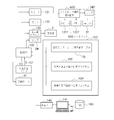
- FIG. 4 shows an electrical configuration example of the infusion pump 1.
- the infusion pump 1 has a control unit 100 that controls judgment and control of the overall operation of the infusion pump 1.
- the liquid feeding drive unit 60 includes a drive motor 61, a cam structure 62 having a plurality of cams driven to rotate by the drive motor 61, and a plurality of fingers moved by the cams of the cam structure 62. It has a finger structure 63 (that is, a peristaltic infusion pump).
- the cam structure 62 has a plurality of cams, for example, a plurality of cams 62A to 62F, and the finger structure 63 has a plurality of fingers 63A to 63F corresponding to the plurality of cams 62A to 62F. .
- the plurality of cams 62A to 62F are arranged with a phase difference from each other, and the cam structure 62 is connected to the output shaft 61A of the drive motor 61.
- the plurality of fingers 63A to 63F are sequentially advanced and retracted by a predetermined stroke in the Y direction by the plurality of eccentric cams 62A to 62F.
- the infusion tube 200 is pressed against the infusion tube holding member 500 of the open / close cover 5 along the T direction. For this reason, the medicine in infusion tube 200 can be sent in the T direction. That is, when the plurality of fingers 63A to 63F are individually driven, the plurality of fingers 63A to 63F sequentially press the outer peripheral surface of the infusion tube 200 along the T direction to feed the medicine in the infusion tube 200. .
- control unit 100 controls the peristaltic motion of the plurality of fingers 63A to 63F, thereby causing the fingers 63A to 63F to move forward and backward in sequence, so that the wave travels, so that the blockage point of the infusion tube 200 is set.
- the infusion tube 200 is squeezed and the medicine is fed into the blood vessel of the patient P through the indwelling needle 172.
- the control unit 100 of the infusion pump 1 employs a CPU (central control unit) chip.
- the control unit 100 uses, for example, a one-chip microcomputer to control the overall operation, and includes a ROM (read only memory) 101, a RAM (random access memory) 102, a nonvolatile memory 103, and a clock. 104.
- the clock 104 can correct the current time by a predetermined operation, and can acquire the current time, measure the elapsed time of a predetermined liquid feeding operation, measure the reference time of liquid feeding speed control, and the like.
- a power switch button 4F includes a power switch button 4F, a power switch 111, a display driver 130 and a display 3, a drive motor 61, a speaker 131, a buzzer 132, a lamp 3W, a bubble sensor 51, and an upstream occlusion sensor. 52, the downstream blockage sensor 53, the communication port 140, the operation panel (operation button) 4, and the information terminal 600 on the nurse center side, and manage and control these peripheral elements.
- the switch 111 supplies power to the control unit 100 from one of the power converter unit 112 and the battery 113 by switching between the power converter unit 112 and the battery 113.
- the power converter unit 112 is connected to a commercial AC power source 115 via an outlet 114.
- the battery 113 is a rechargeable secondary battery such as a lithium ion battery.
- the control unit 100 is also connected to the upstream block sensor 52 and the downstream block sensor 53. Thereby, the control part 100 can also monitor the obstruction
- the information terminal 600 on the nurse center side is placed in the nurse center 650 distant from the infusion pump 1, and the above-described display unit 3, lamp 4A, speaker 131, The display unit 3T, the lamp 3WT, the speaker 131T, and the buzzer 132T are the same as the buzzer 132.
- the display unit driver 130 in FIG. 4 drives the display unit 3 in response to a command from the control unit 100, displays the information content and warning message illustrated in FIG. 2, and turns on the LED (light emitting diode) backlight.
- the display can be changed from a “yellow display screen” to a “white display screen” that is a warning screen for a medical worker. Thereby, the possibility that a medical worker can visually recognize is increased.
- the error display lamp 3 ⁇ / b> W is turned on according to a command from the control unit 100.
- the speaker 131 can notify various warning contents instructed by the control unit 100 by voice.
- the buzzer 132 can warn various warnings by sound according to a command from the control unit 100.
- the display unit 3T is driven by a command from the control unit 100 to display the information content and warning message illustrated in FIG. 2 and to turn on the backlight of the LED (light emitting diode).
- the display can be changed from the “display screen” to a “white display screen” which is a warning screen for the medical staff. Thereby, the possibility that a medical worker can visually recognize is increased.
- the error display lamp 3WT is turned on according to a command from the control unit 100.
- the speaker 131T can notify various warning contents instructed by the control unit 100 by voice.
- the buzzer 132T can warn various warnings by sound according to a command from the control unit 100.
- a downstream block signal S3 indicating that the side is blocked is supplied to the control unit 100.
- the upstream blockage sensor 52 and the downstream blockage sensor 53 can detect a state in which the internal pressure of the infusion circuit exceeds the set pressure in the infusion pump 1 and the medicine cannot be delivered.
- the reason why the internal pressure of the infusion circuit exceeds the set pressure in the infusion pump 1 is that there is a so-called “needle detachment” in which the tip of the infusion needle 172 for infusion shown in FIG.
- needle detachment in which the tip of the infusion needle 172 for infusion shown in FIG.
- the inside of the tube 200 is clogged, a part of the infusion tube 200 is crushed or broken, or a high-viscosity drug is used.
- the control unit 100 includes RS-232C (RS: Recommended Serial Standard; a serial input / output interface of a communication system standardized by EIA (American Electronic Industry Association)), a wired communication system, an infrared communication using a wireless LAN, and the like.
- RS-232C Recommended Serial Standard
- EIA American Electronic Industry Association
- wired communication system an infrared communication using a wireless LAN
- infrared communication using a wireless LAN and the like.
- bidirectional communication with a computer 141 such as a desktop computer is possible through the communication port 140.
- the computer 141 is connected to a drug database (DB) 160, and the drug library MF stored in the drug database 160 is acquired by the control unit 100 via the computer 141 as necessary, and the control unit 100 100 nonvolatile memories 103 can be stored.
- the control unit 100 can display the drug library MF and the like on the display unit 3 shown in FIG.
- the drug information MF includes, for example, drug manufacturer name, drug name, upper and lower limit values of drug administration scheduled amount (mL), upper and lower limit values of flow rate (mL / h), contraindication information, etc. 8 (A) is included.
- the upstream occlusion sensor 52 shown in FIG. 4 detects whether the infusion tube 200 is occluded on the upstream side 200 ⁇ / b> A of the infusion tube 200, and the control unit 100 detects the infusion tube 200.
- This is a sensor for sending an upstream block signal S2 indicating that the upstream side is blocked.
- the downstream blockage sensor 53 detects whether or not the inside of the infusion tube 200 is blocked on the downstream side 200B of the infusion tube 200 (the degree to which the inner diameter and the outer diameter of the infusion tube 200 slightly expand in the radial direction in FIG.
- the upstream blockage sensor 52 and the downstream blockage sensor 53 have the same configuration.
- a case where the downstream side of the infusion tube 200 is blocked a case where a so-called “needle disengagement” in which the tip of the infusion needle 172 for infusion shown in FIG.
- An example of using the downstream occlusion sensor 53 to detect the “needle detachment” phenomenon will be described later.
- FIG. 5 is a block diagram showing a part of the electrical configuration example of the infusion pump 1 shown in FIG. 4 in more detail.
- the non-volatile memory 103 of the control unit 100 shown in FIG. 5 includes an occlusion precaution reference value table TB, an occlusion pressure rapid increase detection processing program PIP for the infusion tube 200, and an occlusion pressure rapid decrease detection processing program PDP for the infusion tube 200. Is remembered.
- the control unit 100 can acquire the occlusion precaution reference value table TB from the medicine database (DB) 160 on the computer 141 side through the communication port 140.
- DB medicine database
- This occlusion precaution is a preventive function of “detecting needle removal at the tip of the indwelling needle 172” using a change in the occlusion pressure in the infusion tube 200.
- Specific examples of the blockage precaution reference value table TB, the blockage pressure rapid increase detection processing program PIP of the infusion tube 200, and the blockage pressure rapid decrease detection process program PDP of the infusion tube 200 will be described later.
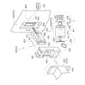
- FIG. 6 is an exploded perspective view showing a structural example of the upstream blockage sensor 52 and the downstream blockage sensor 53. As illustrated in FIG. 6, the upstream blockage sensor 52 and the downstream blockage sensor 53 have the same structure.
- a hole 400 is provided in the surface 50 ⁇ / b> S of the tube mounting portion 50.
- a plastic frame member 401 is fitted into the hole 400, and the frame member 401 has a rectangular opening 402.
- the plastic slider 403 is inserted into the accommodation hole 404 in the hole 400, and the slider 403 has a base 405, a tip 406, and a spring 407.
- the leading end 406 of the slider 403 is fitted into the opening 402.
- One end of the spring 407 is attached to the base 405, and the other end of the spring 407 is attached to the protrusion 409 in the accommodation hole 404.
- a Hall element 410 is disposed on the inner surface of the accommodation hole 404.
- Two magnets 411 and 412 are arranged on the base 405.
- the upstream blockage sensor 52 is simply installed by inserting the frame member 401 into the hole 400 and inserting the base 405 into the opening 402 and the accommodation hole 404 while holding the spring 407.
- the downstream blockage sensor 53 can be easily mounted on the surface 50S of the tube mounting portion 50, and the assembly workability of the upstream blockage sensor 52 and the downstream blockage sensor 53 can be improved.
- pressing members 452 and 453 are provided on the inner surface side of the opening / closing cover 5 at positions corresponding to the upstream closing sensor 52 and the downstream closing sensor 53, respectively.
- the pressing members 452 and 453 have a structure that is pressed to the facing frame member side via a spring 441.
- the pressing member 452 is a first pressing member
- the pressing member 453 is a second pressing member.
- the infusion tube 200 can be The upstream occlusion sensor 52 and the downstream occlusion sensor 53 are pressed against the infusion tube 200 so that the occlusion state of the infusion tube 200 can be accurately detected.
- the upstream blockage sensor 52 and the downstream blockage sensor 53 will be described more specifically.
- the infusion tube 200 is moved between the pressing member 452 (453) and the tip 406 of the slider 403 as shown in FIG. It is sandwiched and held by each urging force 441. If the infusion tube 200 is blocked and the diameter of the infusion tube 200 (the outer diameter and the inner diameter slightly expand), the tip 406 follows the change in the diameter of the infusion tube 200 and the left side in the Y direction. Move to.
- the Hall element 410 detects a change in the magnetic flux and sends the movement amount to the control unit 100 as a signal of the change in the magnetic flux.
- the central axis direction of the spring 441 and the central axis direction of the spring 407 coincide with each other, and the springs 441 and 407 sandwich the infusion tube 200 between the pressing member 452 (453) and the distal end portion 406.
- the occlusion state of the infusion tube 200 can be detected with high accuracy by detecting the movement amount of the slider 403 forming the occlusion sensors 52 and 53.
- the occlusion of the infusion tube 200 downstream from the infusion pump 1 is caused by bending (kinking) of the infusion tube 200 or needle removal from the blood vessel (vein) of the indwelling needle 172 described in detail below.
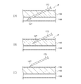
- FIG. 7 shows a state example in which the indwelling needle 172 shown in FIG.
- the pointed tip 197 of the indwelling needle 172 shows the state of the normal indwelling needle 172 inserted and placed in the blood vessel 198 of the patient.
- FIG. 7B and FIG. 7C show an abnormal “needle removal” state of the indwelling needle 172.
- FIG. 7B shows an abnormal insertion state of the indwelling needle 172 in which the distal end 197 of the indwelling needle 172 is out of the blood vessel 198 of the patient P and is positioned in the subcutaneous tissue 199 of the patient P. Yes.
- the distal end 197 of the indwelling needle 172 is disengaged from within the blood vessel 198 of the patient P and completely disengaged from the subcutaneous tissue 199 and the skin 196, not from the subcutaneous tissue 199 of the patient P.
- the abnormal state of the indwelling needle 172 is shown.
- FIG. 8 shows an example of the blocking precaution reference value table TB.
- the block precaution reference value table TB illustrated in FIG. 8A is stored in the nonvolatile memory 103 as shown in FIG.
- the column 1001 of the type of drug in the drug library, the column 1002 of the detection setting level of the blockage state of the infusion tube 200, the column 1003 of the detection judgment value of the blockage pressure sudden increase, and the blockage pressure rapid drop A detection judgment value column 1004 is displayed. As shown in FIG.
- the “detection judgment value M of the closing pressure sudden increase” is a moving average value of about 2 to 3 seconds obtained by the downstream blocking sensor 53 at a sampling interval of every 100 ms, for example. It is a percentage indicating an increase rate (threshold value) with respect to the reference value MN.
- the “decision value N for the sudden decrease in the clogging pressure” is a decrease rate (threshold value) with respect to the latest minimum value obtained by the downstream clogging sensor 53, for example, at a sampling interval of 100 ms. ).
- the concept of “rapid increase” or “rapid decrease” of the occlusion pressure is determined in advance as shown in FIG.
- the detection sensitivity is set to an appropriate sensitivity.
- drug types such as (A) nutrient, (B) antibiotic, (C) antihypertensive, (D) anesthetic, and (E) anticancer drug are listed. Are illustrated.
- the control unit 100 communicates with a computer 141 such as a desktop computer through the communication port 140, thereby allowing the medicine library MF stored in the medicine database 160 to be used. It can be acquired by the control unit 100.
- the types and order of drugs described in the occlusion precaution reference value table TB are merely examples, and the types of drugs and the order of description are not particularly limited.
- Detection setting level 1 is (A) nutrient, detection setting level 2 is (B) antibiotic, detection setting level 3 is (C) antihypertensive, detection setting level 4 is (D) anesthetic, and detection setting level 5 is (E) an anticancer agent.
- the detection judgment value column 1003 for the sudden increase in the obstruction pressure in FIG. 8A shows the detection judgment value M for the sudden increase in the obstruction pressure corresponding to the detection setting level 1 to the detection setting level 5.
- a column 1004 shows the detection judgment value N of the blockage pressure sudden drop corresponding to the detection setting level 1 to the detection setting level 5.
- the detection judgment value M for the blockage pressure sudden increase and the detection judgment value N for the blockage pressure sudden drop are averages obtained by the downstream blockage sensor 53 at a predetermined interval, for example, every 100 ms.
- an increase rate (threshold value) with respect to a value set as a reference value MN at a predetermined interval (every 2 minutes) that is longer than the sampling interval is shown. Percentage.
- the occlusion pressure threshold PP shown in FIG. 8B is a value at which the control unit 100 determines that the infusion tube 200 is occluded, sounds an alarm, and stops liquid feeding. The occlusion pressure threshold PP is corrected according to the environmental temperature. In FIG.
- the detection judgment value M of the occlusion pressure sudden rise is, for example, a threshold of 90% rise from the reference value MN in the detection setting level 1.
- a threshold of 90% rise from the reference value MN in the detection setting level 1 At detection setting level 2, an increase of 80% from the above-mentioned reference value MN is a threshold, at detection setting level 3, a case of an increase of 70% from the above-mentioned reference value MN is a threshold, and at detection setting level 4, an increase of 60% from the above-mentioned reference value MN
- the threshold value is set for the case, and the detection setting level 5 is set with a 50% increase from the reference value MN as a threshold value.
- the detection judgment value N of the closing pressure sudden drop is 100% lower than the reference value MN at the detection setting level 1.
- detection setting level 2 80% lowering from the above-mentioned latest minimum value is a threshold
- 60% lowering from the above-mentioned reference value MN is a threshold
- detection setting level 4 40% from the above-mentioned reference value MN.
- the lowering is set as a threshold
- at the detection setting level 5 20% lowering from the above-described reference value MN is set as a threshold.
- the “needle removal detection (occlusion precaution) When the “)” flag is “ON”, the control unit 100 monitors “detecting needle removal (blocking precaution)”.
- the detection setting level of “needle detachment detection (occlusion precaution)” is, for example, a setting level of a plurality of stages, or a detection setting level from an occlusion pressure detection setting level 1 (low sensitivity).
- the setting of 55 levels is made in advance, and the detection setting level is designated according to the type of medicine from one detection setting level of these 5 levels.
- This “needle detachment detection (occlusion precaution)” is effective only while the medicine is being delivered by the infusion tube 200. Note that the number of levels is not limited to 5, and may be 3 levels.
- the control unit 100 in FIG. 5 is obtained by sampling every 100 ms in accordance with the obstruction pressure sudden increase detection processing program PIP of the infusion tube 200 shown in FIG.
- the obstruction AD analog-digital conversion
- the difference between the obstruction AD value two minutes ago and the current obstruction AD value is greater than or equal to a certain value, ⁇ Occlusion AD value before 2 minutes-Current occlusion AD value> Detection judgment value M of occlusion pressure sudden increase>
- the difference between the occlusion AD value after 2 minutes and the current occlusion AD value is a certain value, that is, ⁇ Occlusion AD value after 2 minutes ⁇ Current occlusion AD value ⁇ Detection judgment value M of occlusion pressure sudden increase>
- the detection judgment value M for the sudden increase in occlusion shown in FIG. 8 employs a value obtained by multiplying the reference value MN at that time by a ratio selected from five levels.
- the control unit 100 in FIG. 5 makes the occlusion pressure abruptly according to the occlusion pressure rapid decrease detection processing program PDP of the infusion tube 200 shown in FIG.
- PDP the occlusion pressure rapid decrease detection processing program
- the occlusion pressure decreases more than a certain amount, that is, ⁇ Current occlusion AD value ⁇ latest minimum AD value ⁇ detection value N of occlusion pressure sudden drop>
- “needle removal detection (blocking precaution)” is displayed on, for example, the display unit 3 shown in FIG. 5, the buzzer 132 is sounded, or the speaker 131 is audibly voiced to the medical staff.
- the threshold value is 20%. If the same specification is used for the detection of the sudden decrease in the obstruction pressure, if the obstruction pressure AD value two minutes ago is in the process of sudden decrease, there is a possibility that “needle removal detection (occlusion precaution)” cannot be performed. There is no way to detect sudden changes. In the case of detecting the sudden decrease in the occlusion pressure, there is no time limit of 2 minutes from the latest minimum AD value to the current occlusion AD value. As the latest minimum AD value, the latest AD value at the time when the AD value starts to increase from the decrease after the infusion pump 1 starts the drug delivery operation is used (the occlusion pressure increases). The latest minimum AD value is obtained as follows.
- FIGS. 9 and 10 in the infusion pump 1, a phenomenon that the tip 197 of the indwelling needle 172 is removed from the blood vessel 198 as shown in FIGS. 7 (A) and 7 (B), so-called “needle”.
- a precaution (preventive measure) function for monitoring an abrupt change in the occlusion pressure will be described although the infusion tube 200 does not reach the occlusion state in order to detect “displacement”.
- FIG. 9 is a flowchart showing an example of monitoring when the occlusion pressure rapidly rises during the delivery of the drug through the infusion tube 200, and FIG. 10 shows the occlusion pressure suddenly during the delivery of the drug through the infusion tube 200.
- step ST1 of FIG. 9 the medical staff inserts the indwelling needle 172 into the blood vessel 198 of the patient P as shown in FIG. And when a medical worker pushes on the power switch 4F shown in FIG. 4 and switches on, the control part 100 will operate the drive motor 61 of the liquid feeding drive part 60, and the cam structure 62 will press the infusion tube 200. Then, the drug is fed into the blood vessel 198 of the patient P through the infusion tube 200 and the indwelling needle 172 as shown in FIG.
- step ST1 in FIG. 9 when the medicine is being delivered to the patient P through the infusion tube 200 and the indwelling needle 172 in FIG. 2, the downstream occlusion sensor 53 in FIG.
- the blockage signal S3 is sent to the control unit 100, and in step ST3 and step ST4, the control unit 100 determines whether or not the blockage pressure in the infusion tube 200 of FIG.
- step ST3 the control unit 100 determines that the occlusion pressure in the infusion tube 200 in FIG. 2 is rapidly increased by the downstream occlusion signal S3.
- step ST4 the control unit 100 determines whether or not the reference value MN
- the detection sensitivity 1 to the detection sensitivity 5 is specified according to the magnitude of the percentage (%) that is an increase rate.
- the detection setting value M for the increase in the occlusion pressure is increased because the detection setting level 5 is the occlusion state.
- the threshold is specified as 50% as a percentage (%).
- the control unit 100 starts from the insertion state of the normal indwelling needle 172 in FIG.
- the distal end 197 of the indwelling needle 172 of 7 (B) has been removed from the blood vessel 198 of the patient P and has been inserted into the subcutaneous tissue 199 of the patient P “An abnormal indwelling needle 172 has been inserted” Judging.
- the control unit 100 sounds a buzzer 132 in FIG. 5 to warn the medical staff that the indwelling needle 172 may be dislodged.
- step ST5-2 the control unit 100 displays a warning on the display unit 3 in FIG. 5 to warn the medical staff that the indwelling needle 172 may be dislodged.
- step ST5-3 the control unit 100 warns the medical staff that there is a possibility that the indwelling needle 172 is dislodged by voice guidance through the speaker 131 of FIG.
- One of these warning means may be used, or a plurality of warning means may be combined.
- the control unit 100 shown in FIG. 5 notifies the information terminal 600 on the nurse center side and rings the buzzer 132 T as necessary in step ST 6. This warns the medical staff that the indwelling needle 172 may be dislodged.
- the control unit 100 displays the information on the display unit 3T in FIG. 5 to warn the medical staff that the indwelling needle 172 may be dislodged, and the control unit 100 performs FIG. The medical staff is warned through voice guidance through the speaker 131T that the indwelling needle 172 may be dislodged.
- the lamp 3WT is turned on to warn that the indwelling needle 172 may be dislodged.
- warning means may be used, or a plurality of warning means may be combined.
- the control unit 100 removes the distal end 197 of the indwelling needle 172 of FIG. 7B from the blood vessel 198 of the patient P from the normal insertion state of the indwelling needle 172 of FIG. If it has been inserted into the subcutaneous tissue 199 of P, a warning is given to the medical staff using warning means, but in step ST7, the liquid feeding operation of the drug in the infusion pump 1 is continued without being stopped, After the medical staff confirms the state of the needle, the medicine feeding operation is stopped if necessary by the judgment of the medical staff.
- step ST8 the control unit 100 determines that the occlusion pressure in the infusion tube 200 of FIG. 2 is rapidly decreasing based on the downstream occlusion signal S3.
- step ST9 the control unit 100 determines that the latest minimum The detection sensitivity 1 to the detection sensitivity 5 is specified according to the magnitude of the percentage (%) that is a reduction rate with respect to the AD value. For example, when the type of drug in the drug library MF shown in FIG.
- the detection setting value N for the occlusion pressure sudden rise is the reference setting level 5 because the detection setting level 5 is the occlusion
- a percentage (%) that is an increase rate with respect to the value MN is specified as 50% as a threshold value.
- step ST9 of FIG. 10 if ⁇ current occlusion AD value ⁇ latest minimum AD value ⁇ detection value N of occlusion pressure sudden drop> is satisfied, the insertion state of the normal indwelling needle 172 shown in FIG. From FIG. 7C, the tip 197 of the indwelling needle 172 is not inside the subcutaneous tissue 199 of the patient P, but completely outside the subcutaneous tissue 199 and the skin 196. It has become "state”. Accordingly, in step ST10-1, the control unit 100 sounds a buzzer 132 in FIG. 5 to warn the medical staff that the indwelling needle 172 may be dislodged. At the same time, in step ST10-2, the control unit 100 displays a warning on the display unit 3 in FIG.
- step ST10-3 the control unit 100 warns the medical staff that there is a possibility that the indwelling needle 172 has come off the needle through the speaker 131 of FIG.
- One of these warning means may be selected, or a plurality of means may be combined.
- the control unit 100 shown in FIG. 5 notifies the information terminal 600 on the nurse center side and rings the buzzer 132T as necessary in step ST11. To warn healthcare professionals. At the same time, the control unit 100 displays the information on the display unit 3T in FIG. 5 to warn the medical staff that the indwelling needle 172 may be dislodged, and the control unit 100 performs FIG. The medical staff is warned by voice through the speaker 131T that there is a possibility that the indwelling needle 172 has come off. In addition to this, the lamp 3WT is turned on to warn that the indwelling needle 172 may be dislodged.
- warning means may be selected, or a plurality of means may be combined.
- the control unit 100 removes the distal end 197 of the indwelling needle 172 of FIG. 7C from the inside of the blood vessel 198 of the patient P from the insertion state of the normal indwelling needle 172 of FIG. If it is out of the skin of P, the health care worker is warned by using a warning means, but in step ST12, the medicine feeding operation in the infusion pump 1 is continued without being stopped. After confirming the state of the needle, if necessary, the medicine feeding operation is stopped according to the judgment of the medical staff. In step ST8, when the occlusion pressure does not drop rapidly, the process returns to step ST3 in FIG. 9 and the subsequent steps are executed from step ST3.
- an anticancer drug is delivered into a patient's blood vessel by infusion over about 3 to 4 hours.
- An infusion pump 1 is a medical pump for injecting a drug by indwelling a distal opening of an indwelling catheter or indwelling needle communicating with an infusion tube in a patient's vein.
- a drive motor for feeding the drug through the infusion tube and the needle, a block sensor for detecting a blockage pressure of the infusion tube when the drug is fed, and a downstream of the medical pump.
- the control unit can detect that the tip of the needle has been removed from the inside of the blood vessel (needle removal) and reliably warn the medical staff.
- the control unit determines that the occlusion pressure suddenly increases or the control unit determines that the occlusion pressure suddenly decreases, the control unit continues the liquid feeding operation without stopping the operation of the drive motor. Let As a result, the liquid supply of the medicine is continued without immediately stopping the operation of the drive motor. Therefore, after the medical worker confirms the state of the needle, the liquid supply operation of the medicine is stopped at the judgment of the medical worker. Can be made.
- the warning means is at least one of a display unit that displays warning contents, a speaker that warns the warning contents by voice, and a buzzer that issues warnings. I can inform you. Since the warning means is arranged at the medical pump and the terminal arranged at the nurse center, it can be surely applied not only to the medical staff around the medical pump but also to the medical staff packed in the nurse center. Therefore, it is possible to stop the liquid feeding operation of the medicine by stopping the drive motor.
- a display unit and an operation panel unit having operation buttons are arranged on the upper part of the main body of the medical pump, and a lower part of the main body of the medical pump is an area where a liquid feeding member for feeding a medicine is arranged It is.
- the medical worker can perform the liquid feeding operation of the medicine by the medical pump while confirming the information on the display unit on the upper part of the main body.
- the medical worker can operate the operation buttons on the operation panel unit while confirming the information on the display unit on the upper part of the main body.
- the present invention is not limited to the above embodiment, and various modifications can be made without departing from the scope of the claims.
- the embodiment of the medical pump of the present invention is a peristaltic infusion pump 1, but is not limited to this, and may be a roller-type infusion pump as another embodiment of the medical pump of the present invention.
- the occlusion AD value is a positive value, but may be a negative value. In that case, ⁇ in the above condition becomes ⁇ .
- a part of each configuration of the above embodiment can be omitted, or can be arbitrarily combined so as to be different from the above.
Abstract
[Problem] To provide a medical-use pump capable of detecting that the tip of a needle has become dislodged from within a blood vessel (needle dislodgement), and reliably warning a health care professional. [Solution] The invention is a medical-use pump for delivering medication through an infusion tube (200) and the tip of a needle attached to the infusion tube to within a blood vessel of a patient, the medical-use pump being provided with: a drive motor (61) which delivers the medication through the infusion tube and the needle; an occlusion sensor (53) which detects occlusion pressure of the infusion tube when delivering the medication; a control unit (100) which, by way of the occlusion pressure of the infusion tube obtained from the occlusion sensor (53), in a case in which the occlusion pressure has suddenly risen by greater than or equal to a threshold, determines that the tip (197) of the needle (172) has been dislodged from within the blood vessel (198) and is positioned outside the skin; and warning means (130, 131, 132) which issue a warning by way of an instruction of the control unit if the occlusion pressure suddenly rises or suddenly falls by greater than or equal to the threshold.
Description
本発明は、薬剤を患者へ送液するための医療用ポンプ、特に輸液ポンプに関する。
The present invention relates to a medical pump, particularly an infusion pump, for delivering a drug to a patient.
医療用ポンプの一例として輸液ポンプは、例えば集中治療室(ICU)等で使用され、患者に対して薬剤の送液処置を、比較的高い精度で比較的長時間行うことに用いられている。輸液ポンプの上には所定の薬剤バッグ(輸液バッグ)が配置され、本体と開閉扉との間には、薬剤バッグから下げた輸液チューブを挟みこんで、この輸液チューブを本体内に収容して開閉扉を閉じることで保持している。輸液ポンプの本体内では、定位置にセットされた輸液チューブの外周面が、本体内の複数のフィンガと開閉扉の内面との間に挟まれている。この輸液ポンプは、複数のフィンガを輸液チューブの外周面を長さ方向に沿って順次押圧して、留置針を通じて患者に対して薬剤の送液を行う蠕動式輸液ポンプである (特許文献1を参照)。
As an example of a medical pump, an infusion pump is used, for example, in an intensive care unit (ICU) or the like, and is used to perform a liquid feeding treatment for a patient for a relatively long time with relatively high accuracy. A predetermined drug bag (infusion bag) is arranged on the infusion pump, and an infusion tube lowered from the drug bag is sandwiched between the main body and the door, and the infusion tube is accommodated in the main body. The door is held by closing the door. In the main body of the infusion pump, the outer peripheral surface of the infusion tube set at a fixed position is sandwiched between a plurality of fingers in the main body and the inner surface of the door. This infusion pump is a peristaltic infusion pump in which a plurality of fingers are sequentially pressed along the length of the outer peripheral surface of an infusion tube to deliver a drug to a patient through an indwelling needle (see Patent Document 1). reference).
特許文献1に記載の輸液ポンプでは、輸液チューブを輸液ポンプの本体内において上から下に向けて垂直に通して保持している。これに対して、輸液チューブを輸液ポンプの本体内において水平方向に通して保持する輸液ポンプが提案されている。このように、輸液チューブを輸液ポンプの本体において水平方向に通して保持する構造を採用しようとするのは、輸液チューブが輸液ポンプの本体内を上から下に向けて垂直に通っている輸液ポンプとは異なり、複数の輸液ポンプを上下位置にスタックした状態で重ねて保持しても輸液チューブが邪魔にならないという利点があるからである。例えば、輸液ポンプの本体に対して向かって右側部分に輸液チューブの上流側が配置され、輸液ポンプの本体に対して向かって左側部分に輸液チューブの下流側が配置されるように予め決められている。この場合には、輸液チューブの上流側を輸液ポンプの本体の右側部分に配置し、輸液チューブの下流側を輸液ポンプの本体の左側部分に配置すれば、薬剤は上流側から下流側に向かって予め定めた送液方向に沿って送液でき、患者に対して正しく送液できる。
In the infusion pump described in Patent Document 1, the infusion tube is held vertically through the infusion pump main body from top to bottom. On the other hand, an infusion pump that holds an infusion tube in a horizontal direction in the body of the infusion pump has been proposed. In this way, the infusion pump has a structure in which the infusion tube is held in the horizontal direction in the main body of the infusion pump so that the infusion tube passes vertically through the main body of the infusion pump from top to bottom. This is because the infusion tube does not get in the way even if a plurality of infusion pumps are stacked and held in a stacked state in the vertical position. For example, the upstream side of the infusion tube is disposed on the right side of the infusion pump main body, and the downstream side of the infusion tube is disposed on the left side of the infusion pump main body. In this case, if the upstream side of the infusion tube is arranged on the right side portion of the main body of the infusion pump and the downstream side of the infusion tube is arranged on the left side portion of the main body of the infusion pump, the drug is directed from the upstream side to the downstream side. Liquid can be fed along a predetermined liquid feeding direction, and liquid can be fed correctly to the patient.
ところで、このような輸液ポンプを使用して、患者に対して薬剤の送液を行う場合には、留置針の針先端は、血管内に挿入されているが、薬剤の送液の途中で、何等かの原因、例えば患者が動いたりする等の原因で、留置針の針先端が血管内から外れて皮膚下の組織内に留まった状態になったり、あるいは留置針の針先端が血管内から外れて皮膚の外に外れてしまう状態になるおそれがある。
もし、留置針の針先端が血管内から外れて皮膚下の組織内に留まった状態で、薬剤が組織内に送液されてしまうと、薬剤の種類によっては患部の組織が壊死する可能性がある。あるいは薬剤の種類によっては組織が壊死しないまでも炎症を起こすおそれもある。このため、留置針の先端が血管内から外れるいわゆる針外れがあると、輸液ポンプは薬剤を患者へ安全に送液できなくなる。
そこで、本発明は、針の先端が血管内から外れたことを検出して、医療従事者に確実に警告することができる医療用ポンプを提供することを目的とする。 By the way, when using such an infusion pump to deliver a drug to a patient, the needle tip of the indwelling needle is inserted into the blood vessel, The needle tip of the indwelling needle comes out of the blood vessel and stays in the tissue under the skin due to some cause, such as the patient moving, or the needle tip of the indwelling needle is left inside the blood vessel. There is a risk that it will come off and come out of the skin.
If the drug is delivered into the tissue while the tip of the indwelling needle is detached from the blood vessel and stays in the tissue under the skin, the affected tissue may be necrotic depending on the type of the drug. is there. Alternatively, depending on the type of drug, there is a risk of inflammation even if the tissue is not necrotic. For this reason, if there is a so-called needle disengagement in which the tip of the indwelling needle comes out of the blood vessel, the infusion pump cannot safely deliver the medicine to the patient.
Then, an object of this invention is to provide the medical pump which can detect that the front-end | tip of the needle | hook remove | deviated from the inside of a blood vessel, and can alert a medical worker reliably.
本発明の医療用ポンプは、輸液チューブと連通する血管内留置用カテーテルまたは留置針の先端開口部を患者の静脈内に留置して薬剤を送液するための医療用ポンプであって、前記薬剤を前記輸液チューブと前記血管内留置用カテーテルまたは留置針を通じて送液させる駆動モータと、前記薬剤を送液する際に前記輸液チューブの閉塞圧を検出する閉塞センサと、当該医療用ポンプにおいて下流側に設けられた前記閉塞センサから得られる前記輸液チューブの閉塞圧により、前記閉塞圧が閾値以上急上昇した場合には前記血管内留置用カテーテルまたは留置針の先端が前記血管内から外れて皮下組織内に位置されていることを判断し、前記閉塞圧の閾値以上の急上昇の後、前記閉塞圧が閾値以上急下降した場合には前記血管内留置用カテーテルまたは留置針の先端が前記血管内から外れて皮膚の外にあると判断する制御部とを備えることを特徴とする。
上記構成によれば、閉塞圧が急上昇した場合には針の先端が血管内から外れて皮下組織内に位置されていることを判断し、閉塞圧が急下降した場合には針の先端が血管内から外れて皮膚の外に位置されていると判断することができる。これにより、針の先端が血管内から外れたこと(針外れ)を検出して、医療従事者に確実に警告することができる。 The medical pump of the present invention is a medical pump for injecting a drug by indwelling a distal opening of an indwelling catheter or indwelling needle communicating with an infusion tube in a patient's vein, A drive motor for feeding the liquid through the infusion tube and the catheter or indwelling needle in the blood vessel, an occlusion sensor for detecting the occlusion pressure of the infusion tube when delivering the drug, and a downstream side in the medical pump When the occlusion pressure suddenly rises above a threshold due to the occlusion pressure of the infusion tube obtained from the occlusion sensor provided in the vessel, the tip of the indwelling catheter or indwelling needle is detached from the inside of the blood vessel, and the inside of the subcutaneous tissue. If the occlusion pressure suddenly rises above the threshold after the sudden rise above the threshold of the occlusion pressure, the catheter for indwelling in the blood vessel is determined. Or the tip of the indwelling needle characterized in that it comprises a control unit which determines that the outside of the skin off from the vessel.
According to the above configuration, when the occlusion pressure suddenly increases, it is determined that the tip of the needle is out of the blood vessel and is positioned in the subcutaneous tissue. It can be determined that it is outside the skin and located outside the skin. Thereby, it is possible to detect that the tip of the needle has been removed from the inside of the blood vessel (needle removal) and to warn a medical worker reliably.
好ましくは、前記制御部が前記閉塞圧の急上昇を判断した場合あるいは前記制御部が前記閉塞圧の急下降を判断した場合であっても、前記制御部は、前記駆動モータの作動を停止せずに、前記薬剤の送液動作を継続させることを特徴とする。
上記構成によれば、駆動モータの作動を直ちには止めずに、薬剤の送液を継続しているので、医療従事者が針の状態を確認した後に、医療従事者の判断により薬剤の送液動作を停止させることができる。 Preferably, the controller does not stop the operation of the drive motor even when the controller determines a sudden increase in the block pressure or when the controller determines a sudden decrease in the block pressure. In addition, the liquid feeding operation of the medicine is continued.
According to the above configuration, since the liquid supply of the medicine is continued without immediately stopping the operation of the drive motor, after the medical worker confirms the state of the needle, the liquid supply of the medicine is made at the judgment of the medical worker. The operation can be stopped.
好ましくは、警告手段をさらに備え、前記警告手段は、警告内容を表示する表示部と、前記警告内容を音声で警告するスピーカと、警告を発報するブザーの少なくとも1つであることを特徴とする。
上記構成によれば、医療従事者は、針外れを警告手段により確実に知らせることができる。 Preferably, warning means is further provided, wherein the warning means is at least one of a display unit that displays warning contents, a speaker that warns the warning contents by voice, and a buzzer that issues a warning. To do.
According to the said structure, the medical worker can notify reliably needle | hook removal by a warning means.
好ましくは、前記警告手段は、前記医療用ポンプと、ナースセンタに配置される端末に配置されていることを特徴とする。
上記構成によれば、医療用ポンプの周囲にいる医療従事者だけでなく、ナースセンタに詰めている医療従事者にも、確実に警告できるので、駆動モータを停止させて薬剤の送液動作を停止させることができる。 Preferably, the warning means is arranged in the medical pump and a terminal arranged in a nurse center.
According to the above configuration, not only the medical staff around the medical pump but also the medical staff packed in the nurse center can be surely warned. Can be stopped.
好ましくは、前記医療用ポンプの本体の上部分には、前記表示部と、操作ボタンを有する操作パネル部が配置され、前記医療用ポンプの本体の下部分は、前記薬剤を送液するための送液部材を配置する領域であることを特徴とする。
上記構成によれば、医療従事者は、本体の上部分の表示部の情報を確認しながら、医療用ポンプによる薬剤の送液作業を行うことができる。そして、医療従事者は、本体の上部分の表示部の情報を確認しながら、操作パネル部の操作ボタンを操作することができる。 Preferably, the display unit and an operation panel unit having operation buttons are arranged on an upper part of the main body of the medical pump, and a lower part of the main body of the medical pump is used for feeding the medicine. It is a region where a liquid feeding member is arranged.
According to the said structure, the medical worker can perform the liquid feeding operation | movement of the chemical | medical agent by a medical pump, confirming the information of the display part of the upper part of a main body. Then, the medical worker can operate the operation buttons on the operation panel unit while confirming the information on the display unit on the upper part of the main body.
本発明は、針の先端が血管内から外れたこと(針外れ)を検出して、医療従事者に確実に警告することができる医療用ポンプを提供することができる。
The present invention can provide a medical pump that can reliably detect a warning to a medical worker by detecting that the tip of the needle is detached from the blood vessel (needle removal).
以下に、本発明の好ましい実施形態を、図面を参照して詳しく説明する。
尚、以下に述べる実施の形態は、本発明の好適な具体例であるから、技術的に好ましい種々の限定が付されているが、本発明の範囲は、以下の説明において特に本発明を限定する旨の記載がない限り、これらの態様に限られるものではない。
図1は、本発明の医療用ポンプの好ましい実施形態である輸液ポンプを示す斜視図である。図2は、図1に示す輸液ポンプをW方向から見た図である。 Hereinafter, preferred embodiments of the present invention will be described in detail with reference to the drawings.
The embodiments described below are preferred specific examples of the present invention, and thus various technically preferable limitations are given. However, the scope of the present invention is particularly limited in the following description. Unless otherwise stated, the present invention is not limited to these embodiments.
FIG. 1 is a perspective view showing an infusion pump which is a preferred embodiment of the medical pump of the present invention. FIG. 2 is a view of the infusion pump shown in FIG. 1 as viewed from the W direction.
図1と図2に示す輸液ポンプ1は、医療用ポンプの一例である。
図2に示すように、輸液ポンプ1は、薬剤171を充填した薬剤バッグ170から、クレンメ179と輸液チューブ200と針(留置針または血管内留置用カテーテル)172を介して、患者Pの血管内に正確に送液することができる。薬剤は輸液剤ともいう。輸液チューブは輸液ラインともいう。 The infusion pump 1 shown in FIGS. 1 and 2 is an example of a medical pump.
As shown in FIG. 2, the infusion pump 1 is provided in the blood vessel of the patient P from themedicine bag 170 filled with the medicine 171 via the clamp 179, the infusion tube 200, and the needle (indwelling needle or catheter for intravascular placement) 172. The liquid can be delivered accurately. The drug is also called an infusion. An infusion tube is also called an infusion line.
図2に示すように、輸液ポンプ1は、薬剤171を充填した薬剤バッグ170から、クレンメ179と輸液チューブ200と針(留置針または血管内留置用カテーテル)172を介して、患者Pの血管内に正確に送液することができる。薬剤は輸液剤ともいう。輸液チューブは輸液ラインともいう。 The infusion pump 1 shown in FIGS. 1 and 2 is an example of a medical pump.
As shown in FIG. 2, the infusion pump 1 is provided in the blood vessel of the patient P from the
輸液ポンプ1は、本体カバー2と取手2Tを有しており、取手2TはN方向に伸ばしたりT方向に収納したりすることができる。この本体カバー2は、本体ともいい、耐薬品性を有する成型樹脂材料により一体成型されており、仮に薬剤等がかかっても輸液ポンプ1の内部に侵入するのを防ぐことができる防滴処理構造を有している。このように、本体カバー2が防滴処理構造を有しているのは、上方に配置されている薬剤バッグ170内の薬剤171がこぼれ落ちたり、周辺で用いる消毒液等が飛散して付着することがあるためである。
The infusion pump 1 has a main body cover 2 and a handle 2T, and the handle 2T can be extended in the N direction or stored in the T direction. The main body cover 2 is also called a main body, and is integrally formed of a molded resin material having chemical resistance, and can be prevented from entering the infusion pump 1 even if a drug or the like is applied. have. As described above, the main body cover 2 has the drip-proof treatment structure because the medicine 171 in the medicine bag 170 disposed above spills out or disinfects the disinfecting liquid used in the vicinity. Because there is.
まず、輸液ポンプ1の本体カバー2に配置された要素について説明する。
図1と図2に示すように、本体カバー2の上部分2Aには、表示部3と、操作パネル部4が配置されている。表示部3は、画像表示装置であり、例えばカラー液晶表示装置を用いている。この表示部3は、日本語表記による情報表記だけでなく、必要に応じて複数の外国語による情報の表示を行うことができる。表示部3は、本体カバー2の上部分2Aの左上位置であって、開閉カバー5の上側に配置されている。本体カバー2の上部分2Aは、本体カバー2の上半分の部分である。本体カバー2の下部分2Bは、本体カバー2の下半分の部分である。
輸液ポンプ1の本体カバー2の上部分2Aには、情報を表示する表示部3と、複数の操作ボタンを有する操作パネル部4が配置され、輸液ポンプ1の本体カバー2の下部分2Bは、薬剤を送液するための送液部材である輸液チューブ200を配置する領域である。これにより、医療従事者は、本体カバー2の上部分2Aの表示部3の情報を確認しながら、輸液ポンプ1による薬剤の送液作業を行うことができる。そして、医療従事者は、本体カバー2の上部分2Aの表示部3の情報を確認しながら、操作パネル部4の操作ボタンを操作することができる。このため、輸液ポンプ1の操作性が良好である。 First, the elements disposed on themain body cover 2 of the infusion pump 1 will be described.
As shown in FIGS. 1 and 2, adisplay unit 3 and an operation panel unit 4 are arranged on the upper portion 2 </ b> A of the main body cover 2. The display unit 3 is an image display device, and uses, for example, a color liquid crystal display device. This display unit 3 can display not only information notation in Japanese but also information in a plurality of foreign languages as required. The display unit 3 is disposed on the upper left side of the upper portion 2 </ b> A of the main body cover 2 and above the opening / closing cover 5. The upper portion 2 </ b> A of the main body cover 2 is an upper half portion of the main body cover 2. The lower part 2 </ b> B of the main body cover 2 is a lower half part of the main body cover 2.
Adisplay portion 3 for displaying information and an operation panel portion 4 having a plurality of operation buttons are arranged on the upper portion 2A of the body cover 2 of the infusion pump 1, and a lower portion 2B of the body cover 2 of the infusion pump 1 is This is a region where an infusion tube 200 which is a liquid feeding member for feeding a medicine is arranged. Thereby, the medical worker can perform the liquid feeding operation of the medicine by the infusion pump 1 while confirming the information on the display unit 3 of the upper portion 2A of the main body cover 2. Then, the medical staff can operate the operation buttons on the operation panel unit 4 while checking the information on the display unit 3 of the upper portion 2A of the main body cover 2. For this reason, the operability of the infusion pump 1 is good.
図1と図2に示すように、本体カバー2の上部分2Aには、表示部3と、操作パネル部4が配置されている。表示部3は、画像表示装置であり、例えばカラー液晶表示装置を用いている。この表示部3は、日本語表記による情報表記だけでなく、必要に応じて複数の外国語による情報の表示を行うことができる。表示部3は、本体カバー2の上部分2Aの左上位置であって、開閉カバー5の上側に配置されている。本体カバー2の上部分2Aは、本体カバー2の上半分の部分である。本体カバー2の下部分2Bは、本体カバー2の下半分の部分である。
輸液ポンプ1の本体カバー2の上部分2Aには、情報を表示する表示部3と、複数の操作ボタンを有する操作パネル部4が配置され、輸液ポンプ1の本体カバー2の下部分2Bは、薬剤を送液するための送液部材である輸液チューブ200を配置する領域である。これにより、医療従事者は、本体カバー2の上部分2Aの表示部3の情報を確認しながら、輸液ポンプ1による薬剤の送液作業を行うことができる。そして、医療従事者は、本体カバー2の上部分2Aの表示部3の情報を確認しながら、操作パネル部4の操作ボタンを操作することができる。このため、輸液ポンプ1の操作性が良好である。 First, the elements disposed on the
As shown in FIGS. 1 and 2, a
A
図2では、表示部3には、一例として薬剤投与の予定量(mL)の表示欄3B、薬剤投与の積算量(mL)の表示欄3C、充電履歴の表示欄3D、流量(mL/h)の表示欄3E等が表示されているが、図1に示す表示部3ではこれらの表示内容の図示は、図面の簡単化のために省略している。表示部3は、この他に警告メッセージを表示することもできる。また、表示部3は、LED(発光ダイオード)のバックライトを点灯することで、例えば「黄色の表示画面」から、医療従事者に対する警告画面である「白色の表示画面」に表示変更することができる。
操作パネル部4は、本体カバー2の上部分2Aにおいて表示部3の右側に配置され、操作パネル部4には、操作ボタンとしては、図示例では、例えば動作インジケータの機能を果たすランプ4A(LEDなどで形成され、正常動作時には緑色に点滅または点灯、異常動作時には赤色に点滅または点灯)、早送りスイッチボタン4B、開始スイッチボタン4C、停止スイッチボタン4D、メニュー選択ボタン4E、電源スイッチ4F等が配置されている。 In FIG. 2, for example, thedisplay unit 3 includes a display column 3B for a scheduled dose (mL) of drug administration, a display column 3C for an accumulated dose (mL) of drug administration, a display column 3D for a charge history, and a flow rate (mL / h). In the display section 3 shown in FIG. 1, illustration of these display contents is omitted for simplification of the drawing. The display unit 3 can also display a warning message. In addition, the display unit 3 can change the display from, for example, a “yellow display screen” to a “white display screen” that is a warning screen for medical workers by turning on the backlight of an LED (light emitting diode). it can.
Theoperation panel unit 4 is disposed on the right side of the display unit 3 in the upper part 2A of the main body cover 2, and the operation panel unit 4 includes, as an operation button, a lamp 4A (LED that functions as, for example, an operation indicator in the illustrated example. Etc., and blinks or lights green during normal operation, blinks or lights red during abnormal operation), fast-forward switch button 4B, start switch button 4C, stop switch button 4D, menu selection button 4E, power switch 4F, etc. Has been.
操作パネル部4は、本体カバー2の上部分2Aにおいて表示部3の右側に配置され、操作パネル部4には、操作ボタンとしては、図示例では、例えば動作インジケータの機能を果たすランプ4A(LEDなどで形成され、正常動作時には緑色に点滅または点灯、異常動作時には赤色に点滅または点灯)、早送りスイッチボタン4B、開始スイッチボタン4C、停止スイッチボタン4D、メニュー選択ボタン4E、電源スイッチ4F等が配置されている。 In FIG. 2, for example, the
The
図1に示すように、本体カバー2の下部分2Bには、蓋部材としての開閉カバー5が回転軸5Aを中心として、R方向に開閉可能に設けられている。開閉カバー5は、X方向に沿って長く形成されている板状の蓋部材である。チューブ装着部50と送液駆動部60は、開閉カバー5の内側に配置されている。このチューブ装着部50には、例えば軟質塩化ビニル等の可撓性の熱可塑性樹脂製の輸液チューブ200をセットして、この開閉カバー5を閉じることで、輸液チューブ200は、チューブ装着部50において、X方向(T方向)に沿って水平に装着できる。
なお、図1と図2におけるX方向、Y方向、Z方向は互いに直交しており、Z方向は上下方向である。X方向は、送液方向であるT方向と平行であり輸液ポンプ1の左右方向である。Y方向は、輸液ポンプ1の前後方向である。 As shown in FIG. 1, an opening /closing cover 5 serving as a lid member is provided on the lower portion 2B of the main body cover 2 so as to be openable and closable in the R direction around a rotating shaft 5A. The open / close cover 5 is a plate-like lid member that is formed long along the X direction. The tube mounting part 50 and the liquid feeding drive part 60 are disposed inside the opening / closing cover 5. An infusion tube 200 made of a flexible thermoplastic resin such as soft vinyl chloride is set in the tube mounting portion 50, and the infusion tube 200 is connected to the tube mounting portion 50 by closing the open / close cover 5. , And can be mounted horizontally along the X direction (T direction).
Note that the X direction, the Y direction, and the Z direction in FIGS. 1 and 2 are orthogonal to each other, and the Z direction is the vertical direction. The X direction is parallel to the T direction, which is the liquid feeding direction, and is the left-right direction of the infusion pump 1. The Y direction is the front-rear direction of the infusion pump 1.
なお、図1と図2におけるX方向、Y方向、Z方向は互いに直交しており、Z方向は上下方向である。X方向は、送液方向であるT方向と平行であり輸液ポンプ1の左右方向である。Y方向は、輸液ポンプ1の前後方向である。 As shown in FIG. 1, an opening /
Note that the X direction, the Y direction, and the Z direction in FIGS. 1 and 2 are orthogonal to each other, and the Z direction is the vertical direction. The X direction is parallel to the T direction, which is the liquid feeding direction, and is the left-right direction of the infusion pump 1. The Y direction is the front-rear direction of the infusion pump 1.
図3は、図1と図2に示す輸液ポンプ1の開閉カバー5を開いて、輸液チューブ200を装着するためのチューブ装着部50を示す斜視図である。
図3に示すように、チューブ装着部50と送液駆動部60は、輸液ポンプ1の本体下部1B側に設けられており、チューブ装着部50と送液駆動部60は、表示部3と操作パネル部4の下部においてX方向に沿って設けられている。チューブ装着部50は、図2に示すように開閉カバー5を、回転軸5Aを中心としてCR方向に閉じると開閉カバー5により覆うことができる。 FIG. 3 is a perspective view showing atube mounting portion 50 for opening the opening / closing cover 5 of the infusion pump 1 shown in FIGS. 1 and 2 and mounting the infusion tube 200.
As shown in FIG. 3, thetube mounting part 50 and the liquid feeding drive part 60 are provided on the main body lower part 1B side of the infusion pump 1, and the tube mounting part 50 and the liquid feeding drive part 60 are operated with the display part 3. A lower portion of the panel portion 4 is provided along the X direction. As shown in FIG. 2, the tube mounting portion 50 can cover the open / close cover 5 with the open / close cover 5 when the open / close cover 5 is closed in the CR direction around the rotation shaft 5A.
図3に示すように、チューブ装着部50と送液駆動部60は、輸液ポンプ1の本体下部1B側に設けられており、チューブ装着部50と送液駆動部60は、表示部3と操作パネル部4の下部においてX方向に沿って設けられている。チューブ装着部50は、図2に示すように開閉カバー5を、回転軸5Aを中心としてCR方向に閉じると開閉カバー5により覆うことができる。 FIG. 3 is a perspective view showing a
As shown in FIG. 3, the
医療従事者は、本体カバー2の上部分2Aの表示部3の情報を確認しながら、チューブ装着部50への輸液チューブ200の装着を行って、開閉カバー5を閉じることができる。そして、医療従事者は、本体カバー2の上部分2Aの表示部3の情報を確認しながら、操作パネル部4の操作ボタンを操作することができる。これにより、医療現場において、輸液ポンプ1の操作性を向上することができる。
図3に示すように、チューブ装着部50は、気泡センサ51と、上流閉塞センサ52と、下流閉塞センサ53と、チューブクランプ部270と、右側位置の第1輸液チューブガイド部54と左側位置の第2輸液チューブガイド部55を有している。 A medical worker can close the open /close cover 5 by attaching the infusion tube 200 to the tube attachment portion 50 while confirming information on the display portion 3 of the upper portion 2 </ b> A of the main body cover 2. Then, the medical staff can operate the operation buttons on the operation panel unit 4 while checking the information on the display unit 3 of the upper portion 2A of the main body cover 2. Thereby, in the medical field, the operativity of the infusion pump 1 can be improved.
As shown in FIG. 3, thetube mounting portion 50 includes a bubble sensor 51, an upstream blockage sensor 52, a downstream blockage sensor 53, a tube clamp portion 270, a first infusion tube guide portion 54 at the right side position, and a left side position. A second infusion tube guide portion 55 is provided.
図3に示すように、チューブ装着部50は、気泡センサ51と、上流閉塞センサ52と、下流閉塞センサ53と、チューブクランプ部270と、右側位置の第1輸液チューブガイド部54と左側位置の第2輸液チューブガイド部55を有している。 A medical worker can close the open /
As shown in FIG. 3, the
図3に示すように、チューブ装着部50の付近には、輸液チューブ200をセットする際に、正しい送液方向であるT方向を明確に表示するための輸液チューブ設定方向表示部150が設けられている。この輸液チューブ設定方向表示部150は、例えば複数の矢印151により構成されている。輸液チューブ設定方向表示部150は、例えばチューブ装着部50の下部に直接印刷しても良いし、シール状の部材に印刷したものをチューブ装着部50の下部に貼り付けても良い。輸液チューブ設定方向表示部150は、開閉カバー5の内側にセットされた輸液チューブ200による薬剤171の正しい方向の送液方向(T方向)を明示するために配置されている。
これにより、医療従事者が、図3の開閉カバー5をCS方向に開けて、チューブ装着部50を開放して、このチューブ装着部50に対して輸液チューブ200を装着する際に、輸液チューブ200による薬剤の送液方向であるT方向を明示できる。このため、医療従事者が、誤って輸液チューブ200を逆方向に装着してしまうことを確実に防ぐことができる。 As shown in FIG. 3, an infusion tube settingdirection display unit 150 for clearly displaying the T direction that is the correct liquid feeding direction when the infusion tube 200 is set is provided in the vicinity of the tube mounting unit 50. ing. The infusion tube setting direction display unit 150 includes, for example, a plurality of arrows 151. The infusion tube setting direction display unit 150 may be printed directly on the lower part of the tube mounting part 50, for example, or may be printed on a seal-like member and attached to the lower part of the tube mounting part 50. The infusion tube setting direction display unit 150 is arranged to clearly indicate the liquid feeding direction (T direction) in the correct direction of the medicine 171 by the infusion tube 200 set inside the opening / closing cover 5.
Accordingly, when the medical staff opens the opening /closing cover 5 of FIG. 3 in the CS direction, opens the tube mounting portion 50, and mounts the infusion tube 200 on the tube mounting portion 50, the infusion tube 200 It is possible to clearly indicate the T direction, which is the direction of drug delivery. For this reason, it can prevent reliably that a medical worker will attach the infusion tube 200 by the reverse direction accidentally.
これにより、医療従事者が、図3の開閉カバー5をCS方向に開けて、チューブ装着部50を開放して、このチューブ装着部50に対して輸液チューブ200を装着する際に、輸液チューブ200による薬剤の送液方向であるT方向を明示できる。このため、医療従事者が、誤って輸液チューブ200を逆方向に装着してしまうことを確実に防ぐことができる。 As shown in FIG. 3, an infusion tube setting
Accordingly, when the medical staff opens the opening /
次に、図3に示す開閉カバー5の構造例を説明する。
図3に示すように、開閉カバー5は、輸液ポンプ1を軽量化するために、薄い成型樹脂部材により作られている板状の部材である。これにより、開閉カバー5の重量を軽減でき、構造を簡単化することができる。開閉カバー5は、チューブ装着部50を、回転軸5Aを中心としてCS方向とCR方向に沿って開閉可能に覆うことができるようにするために、2つのヒンジ部2H、2Hにより本体カバー2の本体下部2Bに対して支持されている。2つのヒンジ部2H、2Hは、第1フック部材5Dと第2フック部材5Eにそれぞれ対応して配置されている。 Next, a structural example of the opening /closing cover 5 shown in FIG. 3 will be described.
As shown in FIG. 3, the open /close cover 5 is a plate-like member made of a thin molded resin member in order to reduce the weight of the infusion pump 1. Thereby, the weight of the opening / closing cover 5 can be reduced, and the structure can be simplified. The opening / closing cover 5 has two hinge portions 2H and 2H that allow the tube mounting portion 50 to be covered so as to be openable and closable along the CS direction and the CR direction about the rotation shaft 5A. It is supported with respect to the main body lower part 2B. The two hinge portions 2H and 2H are arranged corresponding to the first hook member 5D and the second hook member 5E, respectively.
図3に示すように、開閉カバー5は、輸液ポンプ1を軽量化するために、薄い成型樹脂部材により作られている板状の部材である。これにより、開閉カバー5の重量を軽減でき、構造を簡単化することができる。開閉カバー5は、チューブ装着部50を、回転軸5Aを中心としてCS方向とCR方向に沿って開閉可能に覆うことができるようにするために、2つのヒンジ部2H、2Hにより本体カバー2の本体下部2Bに対して支持されている。2つのヒンジ部2H、2Hは、第1フック部材5Dと第2フック部材5Eにそれぞれ対応して配置されている。 Next, a structural example of the opening /
As shown in FIG. 3, the open /
図2と図3に示すように、開閉カバー5の表面側には、右上部分に開閉操作レバー260が設けられている。開閉カバー5の内面側には、輸液チューブ押さえ部材500と、第1フック部材5Dと第2フック部材5Eが設けられている。この輸液チューブ押さえ部材500は、X方向に沿って長く矩形状かつ面状の突出部として配置されており、輸液チューブ押さえ部材500は、送液駆動部60に対面する位置にある。輸液チューブ押さえ部材500は、送液駆動部60に沿ってX方向に平坦面を有しており、輸液チューブ押さえ部材500は、開閉カバー5をCR方向に閉じることで、送液駆動部60との間で輸液チューブ200の一部分を押し付けて挟むようになっている。
医療従事者は、表示部3に表示されている表示内容を確認しながら、輸液チューブ200を輸液ポンプ1の本体の下半分の部分に水平方向に沿ってセットでき、輸液チューブ200がチューブ装着部50にセットされた後に、開閉カバー5は輸液チューブ200を覆うことができる。 As shown in FIGS. 2 and 3, an opening /closing operation lever 260 is provided at the upper right portion on the surface side of the opening / closing cover 5. On the inner surface side of the opening / closing cover 5, an infusion tube pressing member 500, a first hook member 5D, and a second hook member 5E are provided. The infusion tube pressing member 500 is disposed as a long rectangular and planar protrusion along the X direction, and the infusion tube pressing member 500 is in a position facing the liquid feeding drive unit 60. The infusion tube pressing member 500 has a flat surface in the X direction along the liquid feeding drive unit 60, and the infusion tube pressing member 500 closes the opening / closing cover 5 in the CR direction, A part of the infusion tube 200 is pressed between them.
The medical worker can set theinfusion tube 200 on the lower half of the body of the infusion pump 1 along the horizontal direction while confirming the display content displayed on the display unit 3, and the infusion tube 200 is connected to the tube mounting portion. After being set to 50, the opening / closing cover 5 can cover the infusion tube 200.
医療従事者は、表示部3に表示されている表示内容を確認しながら、輸液チューブ200を輸液ポンプ1の本体の下半分の部分に水平方向に沿ってセットでき、輸液チューブ200がチューブ装着部50にセットされた後に、開閉カバー5は輸液チューブ200を覆うことができる。 As shown in FIGS. 2 and 3, an opening /
The medical worker can set the
図3に示すように、第1フック部材5Dと第2フック部材5Eは、本体下部1B側の固定部分1D、1Eに対してそれぞれ機械的に同時に掛かることにより、開閉カバー5は、図2に示すように、本体下部1Bのチューブ装着部50を閉鎖した状態に保持する。この第1フック部材5Dと第2フック部材5Eと、本体下部1B側の固定部分1D、1Eは、開閉カバー5のダブルフック構造部300を構成している。
As shown in FIG. 3, the first hook member 5D and the second hook member 5E are mechanically simultaneously engaged with the fixing portions 1D and 1E on the lower body 1B side, so that the open / close cover 5 is As shown, the tube mounting part 50 of the main body lower part 1B is held in a closed state. The first hook member 5D, the second hook member 5E, and the fixing portions 1D, 1E on the main body lower part 1B side constitute a double hook structure portion 300 of the opening / closing cover 5.
図3に示すチューブクランプ部270は、開閉カバー5を閉じることにより、輸液チューブ200の途中部分をクランプして閉塞させる。チューブクランプ部270は、左側の固定部分1Eの近傍であって、左側の第2フック部材5Eに対応する位置に配置されている。医療従事者が輸液チューブ200をX方向に水平にセットして、医療従事者が開閉カバー5をCR方向に閉じると、チューブクランプ部270は、輸液チューブ200の途中の一部分を閉塞できる。
The tube clamp part 270 shown in FIG. 3 clamps and closes the middle part of the infusion tube 200 by closing the open / close cover 5. The tube clamp portion 270 is disposed in the vicinity of the left fixed portion 1E and at a position corresponding to the left second hook member 5E. When the medical worker sets the infusion tube 200 horizontally in the X direction and the medical worker closes the opening / closing cover 5 in the CR direction, the tube clamp portion 270 can block a part of the infusion tube 200 in the middle.
図3に示すように、第1輸液チューブガイド部54は、本体下部1Bおいて向かって右側部分に設けられ、第2輸液チューブガイド部55は、本体下部1Bにおいて向かって左側部分に設けられている。第1輸液チューブガイド部54は、輸液チューブ200の上流側200Aをはめ込むことで保持でき、第2輸液チューブガイド部55は、輸液チューブ200の下流側200Bをはめ込むことで保持でき、輸液チューブ200をX方向に沿って水平方向に保持するようになっている。このように、水平方向に保持された輸液チューブ200は、気泡センサ51と、上流閉塞センサ52と、送液駆動部60と、下流閉塞センサ53と、そしてチューブクランプ部270に沿って、T方向に沿ってはめ込んで固定される。
As shown in FIG. 3, the first infusion tube guide portion 54 is provided on the right side of the main body lower portion 1B, and the second infusion tube guide portion 55 is provided on the left side of the main body lower portion 1B. Yes. The first infusion tube guide portion 54 can be held by fitting the upstream side 200A of the infusion tube 200, and the second infusion tube guide portion 55 can be held by fitting the downstream side 200B of the infusion tube 200, and the infusion tube 200 can be held. It is held in the horizontal direction along the X direction. Thus, the infusion tube 200 held in the horizontal direction is in the T direction along the bubble sensor 51, the upstream block sensor 52, the liquid feed drive unit 60, the downstream block sensor 53, and the tube clamp unit 270. It is fixed by fitting along.
図3に示すように、第2輸液チューブガイド部55は、輸液チューブ200の下流側200Bの一部分を着脱可能に挟んで保持するために、本体下部1Bの側面部分1Sに形成された溝部分である。第1輸液チューブガイド部54と第2輸液チューブガイド部55は、輸液チューブ200を開閉カバー5とチューブ装着部50との間に挟み込んで潰してしまうことが無いように、チューブ装着部50内に確実に装着できる。
As shown in FIG. 3, the second infusion tube guide portion 55 is a groove portion formed in the side surface portion 1 </ b> S of the main body lower portion 1 </ b> B in order to detachably hold a part of the downstream side 200 </ b> B of the infusion tube 200. is there. The first infusion tube guide portion 54 and the second infusion tube guide portion 55 are provided in the tube attachment portion 50 so that the infusion tube 200 is not sandwiched between the opening / closing cover 5 and the tube attachment portion 50 and crushed. Can be installed securely.
図3に示す気泡センサ51は、輸液チューブ200内に生じる気泡(空気)を検出するセンサであり、例えば気泡センサ51は、ポリブタジエン等熱可塑性樹脂で形成された輸液チューブ200の外側から、輸液チューブ200内に流れる薬剤中に含まれる気泡を監視する超音波センサである。超音波センサの超音波発信部から発生する超音波を輸液チューブ200内に流れる薬剤に当てることで、薬剤における超音波の透過率と、気泡における超音波の透過率とが異なることから、超音波受信部は、その透過率の差を検出して気泡の有無を監視する。気泡センサ51は、押し当て部材320と受け部材330を有している。超音波発振部は押し当て部材320に配置されている。超音波受信部は受け部材330に配置されている。
The bubble sensor 51 shown in FIG. 3 is a sensor that detects bubbles (air) generated in the infusion tube 200. For example, the bubble sensor 51 is an infusion tube from the outside of the infusion tube 200 formed of a thermoplastic resin such as polybutadiene. 200 is an ultrasonic sensor for monitoring bubbles contained in a medicine flowing in 200. By applying ultrasonic waves generated from the ultrasonic wave transmitter of the ultrasonic sensor to the drug flowing in the infusion tube 200, the ultrasonic wave transmittance in the drug and the ultrasonic wave transmittance in the bubbles are different. The receiving unit monitors the presence or absence of bubbles by detecting the difference in transmittance. The bubble sensor 51 has a pressing member 320 and a receiving member 330. The ultrasonic oscillator is disposed on the pressing member 320. The ultrasonic wave receiver is disposed on the receiving member 330.
図3に示す上流閉塞センサ52は、輸液チューブ200の上流側200Aにおいて輸液チューブ200内が閉塞しているかどうかを検出するセンサであり、下流閉塞センサ53は、輸液チューブ200の下流側200Bにおいて輸液チューブ200内が閉塞しているかどうかを検出するセンサである。上流閉塞センサ52と下流閉塞センサ53は、同じ構成である。輸液チューブ200が閉塞する場合としては、例えば送液しようとする薬剤の粘度が高いか、薬剤の濃度が高い等の場合である。
The upstream blockage sensor 52 shown in FIG. 3 is a sensor that detects whether or not the inside of the infusion tube 200 is blocked on the upstream side 200A of the infusion tube 200, and the downstream blockage sensor 53 is an infusion solution on the downstream side 200B of the infusion tube 200. It is a sensor that detects whether or not the inside of the tube 200 is closed. The upstream blockage sensor 52 and the downstream blockage sensor 53 have the same configuration. The case where the infusion tube 200 is blocked is, for example, a case where the viscosity of the medicine to be delivered is high or the concentration of the medicine is high.
図3に示すように、開閉カバー5の内面側には、上流閉塞センサ52と下流閉塞センサ53の対応する位置に、それぞれ押圧部材452、453が設けられている。医療従事者が、図3に示すようにチューブ装着部50に輸液チューブ200をセットした後に、図2に示すように開閉カバー5を閉じると、開閉カバー5側の押圧部材452と押圧部材453が輸液チューブ200の一部分を上流側閉塞センサ52と下流側閉塞センサ53側にそれぞれ押し当てることができる。このため、直径が異なる複数種類の輸液チューブ200の内の何れのサイズの輸液チューブ200が輸液ポンプ1に装着されても、開閉カバー5を閉じると上流側閉塞センサ52と下流側閉塞センサ53は、輸液チューブ200の閉塞状態を検出できる。
3, pressing members 452 and 453 are provided on the inner surface side of the opening / closing cover 5 at positions corresponding to the upstream closing sensor 52 and the downstream closing sensor 53, respectively. When the medical worker sets the infusion tube 200 in the tube mounting portion 50 as shown in FIG. 3 and then closes the opening and closing cover 5 as shown in FIG. 2, the pressing member 452 and the pressing member 453 on the opening and closing cover 5 side A part of the infusion tube 200 can be pressed against the upstream blockage sensor 52 and the downstream blockage sensor 53 side, respectively. For this reason, even if the infusion tube 200 of any size among the plural types of infusion tubes 200 having different diameters is attached to the infusion pump 1, when the open / close cover 5 is closed, the upstream side occlusion sensor 52 and the downstream side occlusion sensor 53 are The occlusion state of the infusion tube 200 can be detected.
図4は、輸液ポンプ1の電気的な構成例を示している。
図4に示すように、輸液ポンプ1は、輸液ポンプ1の全体の動作の判断・制御を制御する制御部100を有している。送液駆動部60は、駆動モータ61と、この駆動モータ61により回転駆動される複数個のカムを有するカム構造体62と、このカム構造体62の各カムにより移動される複数のフィンガを有するフィンガ構造体63を有している(即ち、蠕動式の輸液ポンプとなっている。)。
カム構造体62は、複数のカム、例えば複数のカム62A~62Fを有しており、フィンガ構造体63は、複数のカム62A~62Fに対応して複数のフィンガ63A~63Fを有している。複数のカム62A~62Fは互いに位相差を付けて配列されており、カム構造体62は、駆動モータ61の出力軸61Aに連結されている。 FIG. 4 shows an electrical configuration example of the infusion pump 1.
As shown in FIG. 4, the infusion pump 1 has acontrol unit 100 that controls judgment and control of the overall operation of the infusion pump 1. The liquid feeding drive unit 60 includes a drive motor 61, a cam structure 62 having a plurality of cams driven to rotate by the drive motor 61, and a plurality of fingers moved by the cams of the cam structure 62. It has a finger structure 63 (that is, a peristaltic infusion pump).
Thecam structure 62 has a plurality of cams, for example, a plurality of cams 62A to 62F, and the finger structure 63 has a plurality of fingers 63A to 63F corresponding to the plurality of cams 62A to 62F. . The plurality of cams 62A to 62F are arranged with a phase difference from each other, and the cam structure 62 is connected to the output shaft 61A of the drive motor 61.
図4に示すように、輸液ポンプ1は、輸液ポンプ1の全体の動作の判断・制御を制御する制御部100を有している。送液駆動部60は、駆動モータ61と、この駆動モータ61により回転駆動される複数個のカムを有するカム構造体62と、このカム構造体62の各カムにより移動される複数のフィンガを有するフィンガ構造体63を有している(即ち、蠕動式の輸液ポンプとなっている。)。
カム構造体62は、複数のカム、例えば複数のカム62A~62Fを有しており、フィンガ構造体63は、複数のカム62A~62Fに対応して複数のフィンガ63A~63Fを有している。複数のカム62A~62Fは互いに位相差を付けて配列されており、カム構造体62は、駆動モータ61の出力軸61Aに連結されている。 FIG. 4 shows an electrical configuration example of the infusion pump 1.
As shown in FIG. 4, the infusion pump 1 has a
The
図4に示す制御部100の指令により、駆動モータ61の出力軸61Aが回転すると、複数の偏心カム62A~62Fにより複数のフィンガ63A~63Fが順番にY方向に所定ストローク分進退することで、輸液チューブ200はT方向に沿って開閉カバー5の輸液チューブ押さえ部材500に対して押し付けられる。このため、輸液チューブ200内の薬剤は、T方向に送液することができる。すなわち、複数のフィンガ63A~63Fが個別駆動されることで、複数のフィンガ63A~63Fが輸液チューブ200の外周面をT方向に沿って順次押圧して輸液チューブ200内の薬剤の送液を行う。このように、制御部100が、複数のフィンガ63A~63Fの蠕動運動を制御することにより、フィンガ63A~63Fを順次前後進させ、あたかも波動が進行するようにして、輸液チューブ200の閉塞点をT方向に移動させることで、輸液チューブ200をしごいて、留置針172を通じて、患者Pの血管内に薬剤を送液するようになっている。
When the output shaft 61A of the drive motor 61 is rotated by the command of the control unit 100 shown in FIG. 4, the plurality of fingers 63A to 63F are sequentially advanced and retracted by a predetermined stroke in the Y direction by the plurality of eccentric cams 62A to 62F. The infusion tube 200 is pressed against the infusion tube holding member 500 of the open / close cover 5 along the T direction. For this reason, the medicine in infusion tube 200 can be sent in the T direction. That is, when the plurality of fingers 63A to 63F are individually driven, the plurality of fingers 63A to 63F sequentially press the outer peripheral surface of the infusion tube 200 along the T direction to feed the medicine in the infusion tube 200. . In this way, the control unit 100 controls the peristaltic motion of the plurality of fingers 63A to 63F, thereby causing the fingers 63A to 63F to move forward and backward in sequence, so that the wave travels, so that the blockage point of the infusion tube 200 is set. By moving in the T direction, the infusion tube 200 is squeezed and the medicine is fed into the blood vessel of the patient P through the indwelling needle 172.
輸液ポンプ1の制御部100は、CPU(中央制御部)チップを採用している。制御部100は、全体的な動作の制御を行うために、例えばワンチップのマイクロコンピュータを用いており、ROM(読み出し専用メモリ)101,RAM(ランダムアクセスメモリ)102、不揮発性メモリ103、そしてクロック104を有する。クロック104は、所定の操作により現在時刻の修正ができ、現在時刻の取得や、所定の送液作業の経過時間の計測、送液の速度制御の基準時間の計測等ができる。
The control unit 100 of the infusion pump 1 employs a CPU (central control unit) chip. The control unit 100 uses, for example, a one-chip microcomputer to control the overall operation, and includes a ROM (read only memory) 101, a RAM (random access memory) 102, a nonvolatile memory 103, and a clock. 104. The clock 104 can correct the current time by a predetermined operation, and can acquire the current time, measure the elapsed time of a predetermined liquid feeding operation, measure the reference time of liquid feeding speed control, and the like.
図4に示す制御部100は、電源スイッチボタン4Fと電源切り替え用のスイッチ111、表示部ドライバ130と表示部3、駆動モータ61、スピーカ131、ブザー132、ランプ3W、気泡センサ51、上流閉塞センサ52、下流閉塞センサ53、通信ポート140、操作パネル(操作ボタン)4と、ナースセンタ側の情報端末600に接続されており、これらの周辺要素の管理と制御を行っている。表示部3、スピーカ131、ブザー132、動作インジケータの機能を果たすランプ4A(LEDなどで形成され、正常動作時には緑色に点滅または点灯、異常動作時には赤色に点滅または点灯)の少なくとも1つあるいは全部は、輸液チューブ200内における閉塞圧が急上昇した場合あるいは急下降した場合に、制御部100の指令により医療従事者に対して警告を出すための警告手段である。
4 includes a power switch button 4F, a power switch 111, a display driver 130 and a display 3, a drive motor 61, a speaker 131, a buzzer 132, a lamp 3W, a bubble sensor 51, and an upstream occlusion sensor. 52, the downstream blockage sensor 53, the communication port 140, the operation panel (operation button) 4, and the information terminal 600 on the nurse center side, and manage and control these peripheral elements. At least one or all of the display unit 3, the speaker 131, the buzzer 132, and the lamp 4A that functions as an operation indicator (formed by an LED or the like, blinks or lights green during normal operation, and blinks or lights red during abnormal operation) This is a warning means for issuing a warning to the medical staff in response to a command from the control unit 100 when the occlusion pressure in the infusion tube 200 suddenly rises or falls sharply.
スイッチ111は、電源コンバータ部112とバッテリ113を切り換えることで、電源コンバータ部112とバッテリ113の一方から制御部100に対して電源供給する。電源コンバータ部112は、コンセント114を介して商用交流電源115に接続されている。バッテリ113は、例えばリチウムイオン電池等の充放電可能な二次電池である。
また、制御部100は、上流閉塞センサ52と下流閉塞センサ53にも接続されている。これにより、制御部100は、輸液チューブ200内の閉塞状態の監視をもすることができる。輸液ポンプ1が例えば病棟に置かれている場合に、ナースセンタ側の情報端末600は、輸液ポンプ1から離れたナースセンタ650に置かれており、上述した表示部3、ランプ4A、スピーカ131、ブザー132と同様の表示部3T、ランプ3WT、スピーカ131T、ブザー132Tを有している。 Theswitch 111 supplies power to the control unit 100 from one of the power converter unit 112 and the battery 113 by switching between the power converter unit 112 and the battery 113. The power converter unit 112 is connected to a commercial AC power source 115 via an outlet 114. The battery 113 is a rechargeable secondary battery such as a lithium ion battery.
Thecontrol unit 100 is also connected to the upstream block sensor 52 and the downstream block sensor 53. Thereby, the control part 100 can also monitor the obstruction | occlusion state in the infusion tube 200. FIG. When the infusion pump 1 is placed in, for example, a ward, the information terminal 600 on the nurse center side is placed in the nurse center 650 distant from the infusion pump 1, and the above-described display unit 3, lamp 4A, speaker 131, The display unit 3T, the lamp 3WT, the speaker 131T, and the buzzer 132T are the same as the buzzer 132.
また、制御部100は、上流閉塞センサ52と下流閉塞センサ53にも接続されている。これにより、制御部100は、輸液チューブ200内の閉塞状態の監視をもすることができる。輸液ポンプ1が例えば病棟に置かれている場合に、ナースセンタ側の情報端末600は、輸液ポンプ1から離れたナースセンタ650に置かれており、上述した表示部3、ランプ4A、スピーカ131、ブザー132と同様の表示部3T、ランプ3WT、スピーカ131T、ブザー132Tを有している。 The
The
図4の表示部ドライバ130は、制御部100の指令により表示部3を駆動して、図2に例示する情報内容や警告メッセージを表示し、LED(発光ダイオード)のバックライトを点灯させることで、例えば「黄色の表示画面」から、医療従事者に対する警告画面である「白色の表示画面」に表示変更することができる。これにより、医療従事者が視覚で認知できる可能性を高める。エラー表示用のランプ3Wは、制御部100の指令により、点灯する。スピーカ131は、制御部100の指令各種の警告内容を音声により告知することができる。ブザー132は、制御部100の指令により各種の警告を音により警告することができる。
同様にして、制御部100の指令により表示部3Tを駆動して、図2に例示する情報内容や警告メッセージを表示し、LED(発光ダイオード)のバックライトを点灯させることで、例えば「黄色の表示画面」から、医療従事者に対する警告画面である「白色の表示画面」に表示変更することができる。これにより、医療従事者が視覚で認知できる可能性を高める。エラー表示用のランプ3WTは、制御部100の指令により、点灯する。スピーカ131Tは、制御部100の指令各種の警告内容を音声により告知することができる。ブザー132Tは、制御部100の指令により各種の警告を音により警告することができる。 Thedisplay unit driver 130 in FIG. 4 drives the display unit 3 in response to a command from the control unit 100, displays the information content and warning message illustrated in FIG. 2, and turns on the LED (light emitting diode) backlight. For example, the display can be changed from a “yellow display screen” to a “white display screen” that is a warning screen for a medical worker. Thereby, the possibility that a medical worker can visually recognize is increased. The error display lamp 3 </ b> W is turned on according to a command from the control unit 100. The speaker 131 can notify various warning contents instructed by the control unit 100 by voice. The buzzer 132 can warn various warnings by sound according to a command from the control unit 100.
Similarly, thedisplay unit 3T is driven by a command from the control unit 100 to display the information content and warning message illustrated in FIG. 2 and to turn on the backlight of the LED (light emitting diode). The display can be changed from the “display screen” to a “white display screen” which is a warning screen for the medical staff. Thereby, the possibility that a medical worker can visually recognize is increased. The error display lamp 3WT is turned on according to a command from the control unit 100. The speaker 131T can notify various warning contents instructed by the control unit 100 by voice. The buzzer 132T can warn various warnings by sound according to a command from the control unit 100.
同様にして、制御部100の指令により表示部3Tを駆動して、図2に例示する情報内容や警告メッセージを表示し、LED(発光ダイオード)のバックライトを点灯させることで、例えば「黄色の表示画面」から、医療従事者に対する警告画面である「白色の表示画面」に表示変更することができる。これにより、医療従事者が視覚で認知できる可能性を高める。エラー表示用のランプ3WTは、制御部100の指令により、点灯する。スピーカ131Tは、制御部100の指令各種の警告内容を音声により告知することができる。ブザー132Tは、制御部100の指令により各種の警告を音により警告することができる。 The
Similarly, the
図4において、気泡センサ51からの気泡検出信号S1と、上流閉塞センサ52からの輸液チューブ200の上流側が閉塞したことを示す上流閉塞信号S2と、そして下流閉塞センサ53からの輸液チューブ200の下流側が閉塞したことを示す下流閉塞信号S3は、制御部100に供給される。
上流閉塞センサ52と下流閉塞センサ53は、輸液回路の内圧が輸液ポンプ1内の設定圧を越えて、薬剤を送液できない状態を検出することができる。輸液回路の内圧が輸液ポンプ1内の設定圧を越える原因としては、図2に示す輸液用の留置針172の先端が患者Pの血管内から外れるいわゆる「針外れ」が生じた場合や、輸液チューブ200内が詰まっている場合、輸液チューブ200の一部がつぶれているまたは折れている場合、高粘度の薬剤を使用している場合等である。 In FIG. 4, the bubble detection signal S <b> 1 from thebubble sensor 51, the upstream block signal S <b> 2 indicating that the upstream side of the infusion tube 200 from the upstream block sensor 52 is blocked, and the downstream of the infusion tube 200 from the downstream block sensor 53. A downstream block signal S3 indicating that the side is blocked is supplied to the control unit 100.
Theupstream blockage sensor 52 and the downstream blockage sensor 53 can detect a state in which the internal pressure of the infusion circuit exceeds the set pressure in the infusion pump 1 and the medicine cannot be delivered. The reason why the internal pressure of the infusion circuit exceeds the set pressure in the infusion pump 1 is that there is a so-called “needle detachment” in which the tip of the infusion needle 172 for infusion shown in FIG. For example, the inside of the tube 200 is clogged, a part of the infusion tube 200 is crushed or broken, or a high-viscosity drug is used.
上流閉塞センサ52と下流閉塞センサ53は、輸液回路の内圧が輸液ポンプ1内の設定圧を越えて、薬剤を送液できない状態を検出することができる。輸液回路の内圧が輸液ポンプ1内の設定圧を越える原因としては、図2に示す輸液用の留置針172の先端が患者Pの血管内から外れるいわゆる「針外れ」が生じた場合や、輸液チューブ200内が詰まっている場合、輸液チューブ200の一部がつぶれているまたは折れている場合、高粘度の薬剤を使用している場合等である。 In FIG. 4, the bubble detection signal S <b> 1 from the
The
図4において、制御部100は、RS-232C(RS:Recommended Standard;EIA(米国電子工業会)により規格化された通信方式のシリアル入出力インターフェース)や有線の通信方式や無線LANによる赤外線通信等により、通信ポート140を通じて、例えば、デスクトップコンピュータのようなコンピュータ141に対して双方向に通信可能である。このコンピュータ141は、薬剤データベース(DB)160に接続されており、薬剤データベース160に格納されている薬剤ライブラリMFは、必要に応じてコンピュータ141を介して、制御部100に取得して、制御部100の不揮発性メモリ103に記憶させることができる。制御部100は、記憶した薬剤ライブラリMFを基にして、例えば図2に示す表示部3には薬剤ライブラリMF等を表示することができる。なお、薬剤情報MFとしては、例えば、薬剤メーカ名,薬剤名,薬剤投与の予定量(mL)の上限・下限値,流量(mL/h)の上限・下限値,禁忌情報等の他、図8(A)のようなテーブルを含んでいる。
In FIG. 4, the control unit 100 includes RS-232C (RS: Recommended Serial Standard; a serial input / output interface of a communication system standardized by EIA (American Electronic Industry Association)), a wired communication system, an infrared communication using a wireless LAN, and the like. Thus, bidirectional communication with a computer 141 such as a desktop computer is possible through the communication port 140. The computer 141 is connected to a drug database (DB) 160, and the drug library MF stored in the drug database 160 is acquired by the control unit 100 via the computer 141 as necessary, and the control unit 100 100 nonvolatile memories 103 can be stored. The control unit 100 can display the drug library MF and the like on the display unit 3 shown in FIG. 2, for example, based on the stored drug library MF. The drug information MF includes, for example, drug manufacturer name, drug name, upper and lower limit values of drug administration scheduled amount (mL), upper and lower limit values of flow rate (mL / h), contraindication information, etc. 8 (A) is included.
図4を参照すると、図4に示す上流閉塞センサ52は、輸液チューブ200の上流側200Aにおいて輸液チューブ200内が閉塞しているかどうかを検出して、制御部100に対して、輸液チューブ200の上流側が閉塞したことを示す上流閉塞信号S2を送るためのセンサである。
下流閉塞センサ53は、輸液チューブ200の下流側200Bにおいて輸液チューブ200内が閉塞しているかどうかを検出(図6において輸液チューブ200の内径,外径が径方向に僅かに拡径する度合いが輸液チューブ200内の閉塞圧に関係する)して、輸液チューブ200の下流側が閉塞したことを示す下流閉塞信号S3を送るためのセンサである。これらの上流閉塞センサ52と下流閉塞センサ53は、同じ構成である。本発明の実施形態では、輸液チューブ200の下流側が閉塞する場合として、図2に示す輸液用の留置針172の先端が患者Pの血管内から外れるいわゆる「針外れ」が生じた場合について、この「針外れ」現象を検出することに下流閉塞センサ53を利用する例を後程説明する。 Referring to FIG. 4, theupstream occlusion sensor 52 shown in FIG. 4 detects whether the infusion tube 200 is occluded on the upstream side 200 </ b> A of the infusion tube 200, and the control unit 100 detects the infusion tube 200. This is a sensor for sending an upstream block signal S2 indicating that the upstream side is blocked.
Thedownstream blockage sensor 53 detects whether or not the inside of the infusion tube 200 is blocked on the downstream side 200B of the infusion tube 200 (the degree to which the inner diameter and the outer diameter of the infusion tube 200 slightly expand in the radial direction in FIG. This is a sensor for sending a downstream blocking signal S3 indicating that the downstream side of the infusion tube 200 is blocked (related to the blocking pressure in the tube 200). The upstream blockage sensor 52 and the downstream blockage sensor 53 have the same configuration. In the embodiment of the present invention, as a case where the downstream side of the infusion tube 200 is blocked, a case where a so-called “needle disengagement” in which the tip of the infusion needle 172 for infusion shown in FIG. An example of using the downstream occlusion sensor 53 to detect the “needle detachment” phenomenon will be described later.
下流閉塞センサ53は、輸液チューブ200の下流側200Bにおいて輸液チューブ200内が閉塞しているかどうかを検出(図6において輸液チューブ200の内径,外径が径方向に僅かに拡径する度合いが輸液チューブ200内の閉塞圧に関係する)して、輸液チューブ200の下流側が閉塞したことを示す下流閉塞信号S3を送るためのセンサである。これらの上流閉塞センサ52と下流閉塞センサ53は、同じ構成である。本発明の実施形態では、輸液チューブ200の下流側が閉塞する場合として、図2に示す輸液用の留置針172の先端が患者Pの血管内から外れるいわゆる「針外れ」が生じた場合について、この「針外れ」現象を検出することに下流閉塞センサ53を利用する例を後程説明する。 Referring to FIG. 4, the
The
図5は、図4に示す輸液ポンプ1の電気的な構成例の中の一部を、さらに詳しく示すブロック図である。
図5に示す制御部100の例えば不揮発性メモリ103には、閉塞プリコーション基準値テーブルTBと、輸液チューブ200の閉塞圧急上昇検出処理プログラムPIPと、輸液チューブ200の閉塞圧力急下降検出処理プログラムPDPを記憶している。制御部100は、この閉塞プリコーション基準値テーブルTBを、通信ポート140を通じて、コンピュータ141側の薬剤データベース(DB)160から取得することができる。この閉塞プリコーションとは、輸液チューブ200内の閉塞圧の変化を利用した「留置針172の先端の針外れを検出」する予防機能のことである。
これらの閉塞プリコーション基準値テーブルTBと、輸液チューブ200の閉塞圧急上昇検出処理プログラムPIPと、輸液チューブ200の閉塞圧急下降検出処理プログラムPDPの具体例は、後で説明する。 FIG. 5 is a block diagram showing a part of the electrical configuration example of the infusion pump 1 shown in FIG. 4 in more detail.
For example, thenon-volatile memory 103 of the control unit 100 shown in FIG. 5 includes an occlusion precaution reference value table TB, an occlusion pressure rapid increase detection processing program PIP for the infusion tube 200, and an occlusion pressure rapid decrease detection processing program PDP for the infusion tube 200. Is remembered. The control unit 100 can acquire the occlusion precaution reference value table TB from the medicine database (DB) 160 on the computer 141 side through the communication port 140. This occlusion precaution is a preventive function of “detecting needle removal at the tip of the indwelling needle 172” using a change in the occlusion pressure in the infusion tube 200.
Specific examples of the blockage precaution reference value table TB, the blockage pressure rapid increase detection processing program PIP of theinfusion tube 200, and the blockage pressure rapid decrease detection process program PDP of the infusion tube 200 will be described later.
図5に示す制御部100の例えば不揮発性メモリ103には、閉塞プリコーション基準値テーブルTBと、輸液チューブ200の閉塞圧急上昇検出処理プログラムPIPと、輸液チューブ200の閉塞圧力急下降検出処理プログラムPDPを記憶している。制御部100は、この閉塞プリコーション基準値テーブルTBを、通信ポート140を通じて、コンピュータ141側の薬剤データベース(DB)160から取得することができる。この閉塞プリコーションとは、輸液チューブ200内の閉塞圧の変化を利用した「留置針172の先端の針外れを検出」する予防機能のことである。
これらの閉塞プリコーション基準値テーブルTBと、輸液チューブ200の閉塞圧急上昇検出処理プログラムPIPと、輸液チューブ200の閉塞圧急下降検出処理プログラムPDPの具体例は、後で説明する。 FIG. 5 is a block diagram showing a part of the electrical configuration example of the infusion pump 1 shown in FIG. 4 in more detail.
For example, the
Specific examples of the blockage precaution reference value table TB, the blockage pressure rapid increase detection processing program PIP of the
図6は、上流閉塞センサ52および下流閉塞センサ53の構造例を示す分解斜視図である。
図6に例示するように、上流閉塞センサ52および下流閉塞センサ53は同じ構造を有している。チューブ装着部50の表面50Sには、穴部400が設けられている。この穴部400には、プラスチック製の枠部材401がはめ込まれており、枠部材401は長方形の開口部402を有している。プラスチック製のスライダ403は、穴部400内の収容穴部404内に挿入されており、スライダ403は基部405と先端部406とスプリング407を有している。 FIG. 6 is an exploded perspective view showing a structural example of theupstream blockage sensor 52 and the downstream blockage sensor 53.
As illustrated in FIG. 6, theupstream blockage sensor 52 and the downstream blockage sensor 53 have the same structure. A hole 400 is provided in the surface 50 </ b> S of the tube mounting portion 50. A plastic frame member 401 is fitted into the hole 400, and the frame member 401 has a rectangular opening 402. The plastic slider 403 is inserted into the accommodation hole 404 in the hole 400, and the slider 403 has a base 405, a tip 406, and a spring 407.
図6に例示するように、上流閉塞センサ52および下流閉塞センサ53は同じ構造を有している。チューブ装着部50の表面50Sには、穴部400が設けられている。この穴部400には、プラスチック製の枠部材401がはめ込まれており、枠部材401は長方形の開口部402を有している。プラスチック製のスライダ403は、穴部400内の収容穴部404内に挿入されており、スライダ403は基部405と先端部406とスプリング407を有している。 FIG. 6 is an exploded perspective view showing a structural example of the
As illustrated in FIG. 6, the
この開口部402には、スライダ403の先端部406がはめ込まれている。スプリング407の一端部は基部405に取り付けられ、スプリング407の他端部は収容穴部404内の突起409に取り付けられている。収容穴部404の内面には、ホール素子410が配置されている。基部405には、2つのマグネット411,412が配置されている。
The leading end 406 of the slider 403 is fitted into the opening 402. One end of the spring 407 is attached to the base 405, and the other end of the spring 407 is attached to the protrusion 409 in the accommodation hole 404. A Hall element 410 is disposed on the inner surface of the accommodation hole 404. Two magnets 411 and 412 are arranged on the base 405.
このような構造を採用することにより、枠部材401を穴部400に装着し、基部405はスプリング407を保持しながら、開口部402と収容穴部404内に挿入するだけで、上流閉塞センサ52と下流閉塞センサ53は、チューブ装着部50の表面50Sに対して簡単に装着することができ、上流閉塞センサ52と下流閉塞センサ53の組み立て作業性を向上できる。
一方、図4に示すように、開閉カバー5の内面側には、上流閉塞センサ52と下流閉塞センサ53の対応する位置に、それぞれ押圧部材452、453が設けられている。押圧部材452、453は、スプリング441を介して対面している枠部材側に押される構造である。押圧部材452は第1押圧部材であり、押圧部材453は第2押圧部材である。 By adopting such a structure, theupstream blockage sensor 52 is simply installed by inserting the frame member 401 into the hole 400 and inserting the base 405 into the opening 402 and the accommodation hole 404 while holding the spring 407. The downstream blockage sensor 53 can be easily mounted on the surface 50S of the tube mounting portion 50, and the assembly workability of the upstream blockage sensor 52 and the downstream blockage sensor 53 can be improved.
On the other hand, as shown in FIG. 4, pressing members 452 and 453 are provided on the inner surface side of the opening / closing cover 5 at positions corresponding to the upstream closing sensor 52 and the downstream closing sensor 53, respectively. The pressing members 452 and 453 have a structure that is pressed to the facing frame member side via a spring 441. The pressing member 452 is a first pressing member, and the pressing member 453 is a second pressing member.
一方、図4に示すように、開閉カバー5の内面側には、上流閉塞センサ52と下流閉塞センサ53の対応する位置に、それぞれ押圧部材452、453が設けられている。押圧部材452、453は、スプリング441を介して対面している枠部材側に押される構造である。押圧部材452は第1押圧部材であり、押圧部材453は第2押圧部材である。 By adopting such a structure, the
On the other hand, as shown in FIG. 4, pressing
このため、医療従事者が、図3に示すようにチューブ装着部50に輸液チューブ200をセットした後に、図2に示すように開閉カバー5を閉じると、開閉カバー5側の第1押圧部材452と第2押圧部材453が、輸液チューブ200の一部を上流側閉塞センサ52と下流側閉塞センサ53側にそれぞれ押し当てることができる。このため、輸液チューブ200の外径が、製造上の公差のために若干バラツキが有る場合や、輸液チューブ200の製造メーカが違っている場合でも、輸液チューブ200は、開閉カバー5を閉じれば、上流側閉塞センサ52と下流側閉塞センサ53は、輸液チューブ200に押し当てられて、輸液チューブ200の閉塞状態を精度よく検出できるようになっている。
For this reason, when a medical worker sets the infusion tube 200 in the tube mounting portion 50 as shown in FIG. 3 and then closes the opening and closing cover 5 as shown in FIG. 2, the first pressing member 452 on the opening and closing cover 5 side. And the second pressing member 453 can press a part of the infusion tube 200 against the upstream blockage sensor 52 and the downstream blockage sensor 53 side, respectively. For this reason, even when the outer diameter of the infusion tube 200 varies slightly due to manufacturing tolerances or when the manufacturer of the infusion tube 200 is different, the infusion tube 200 can be The upstream occlusion sensor 52 and the downstream occlusion sensor 53 are pressed against the infusion tube 200 so that the occlusion state of the infusion tube 200 can be accurately detected.
上流側閉塞センサ52と下流側閉塞センサ53の構造をさらに具体的に説明する。図2に示すように、開閉カバー5を閉じると、図6に示すように輸液チューブ200は、押圧部材452(453)とスライダ403の先端部406の間において、付勢部材としてのスプリング407,441の各付勢力により挟まれて保持される。もし、輸液チューブ200が閉塞したことで輸液チューブ200の直径(外径,内径が僅かに拡径する)が変わると、先端部406が輸液チューブ200の直径の変化に追従してY方向の左側に移動する。このため、マグネット411,412がホール素子410に対して相対的に移動することで、ホール素子410は磁束の変化を検出して、その移動量を制御部100に磁束の変化の信号として送ることができる。
図6に示すように、スプリング441の中心軸方向とスプリング407の中心軸方向は一致しており、スプリング441,407は、押圧部材452(453)と先端部406の間に輸液チューブ200を挟むことで、輸液チューブ200の直径方向に沿って輸液チューブ200に対して加圧力を与えることができる。このため、閉塞センサ52,53を形成するスライダ403の移動量を検出することにより、輸液チューブ200の閉塞状態を精度よく検出できる。
なお、輸液ポンプ1から下流側の輸液チューブ200の閉塞は、輸液チューブ200の折れ曲り(キンク)や、以下に詳述する留置針172の血管(静脈)からの針外れに起因する。 The structures of theupstream blockage sensor 52 and the downstream blockage sensor 53 will be described more specifically. As shown in FIG. 2, when the open / close cover 5 is closed, the infusion tube 200 is moved between the pressing member 452 (453) and the tip 406 of the slider 403 as shown in FIG. It is sandwiched and held by each urging force 441. If the infusion tube 200 is blocked and the diameter of the infusion tube 200 (the outer diameter and the inner diameter slightly expand), the tip 406 follows the change in the diameter of the infusion tube 200 and the left side in the Y direction. Move to. For this reason, when the magnets 411 and 412 move relative to the Hall element 410, the Hall element 410 detects a change in the magnetic flux and sends the movement amount to the control unit 100 as a signal of the change in the magnetic flux. Can do.
As shown in FIG. 6, the central axis direction of thespring 441 and the central axis direction of the spring 407 coincide with each other, and the springs 441 and 407 sandwich the infusion tube 200 between the pressing member 452 (453) and the distal end portion 406. Thus, it is possible to apply pressure to the infusion tube 200 along the diameter direction of the infusion tube 200. For this reason, the occlusion state of the infusion tube 200 can be detected with high accuracy by detecting the movement amount of the slider 403 forming the occlusion sensors 52 and 53.
The occlusion of theinfusion tube 200 downstream from the infusion pump 1 is caused by bending (kinking) of the infusion tube 200 or needle removal from the blood vessel (vein) of the indwelling needle 172 described in detail below.
図6に示すように、スプリング441の中心軸方向とスプリング407の中心軸方向は一致しており、スプリング441,407は、押圧部材452(453)と先端部406の間に輸液チューブ200を挟むことで、輸液チューブ200の直径方向に沿って輸液チューブ200に対して加圧力を与えることができる。このため、閉塞センサ52,53を形成するスライダ403の移動量を検出することにより、輸液チューブ200の閉塞状態を精度よく検出できる。
なお、輸液ポンプ1から下流側の輸液チューブ200の閉塞は、輸液チューブ200の折れ曲り(キンク)や、以下に詳述する留置針172の血管(静脈)からの針外れに起因する。 The structures of the
As shown in FIG. 6, the central axis direction of the
The occlusion of the
図7は、図2に示す留置針172が患者Pにある状態例を示している。図7(A)では、留置針172の尖った先端197が、患者の血管198内に挿入され、留置されている正常な留置針172の状態を示している。図7(B)と図7(C)は、留置針172の異常な「針外れ」状態を示している。図7(B)では、留置針172の先端197が、患者Pの血管198内から外れて、患者Pの皮下組織199内に位置されてしまっている留置針172の異常な挿入状態を示している。図7(C)では、留置針172の先端197が、患者Pの血管198内から外れて、患者Pの皮下組織199内ではなく、完全に皮下組織199と皮膚196の外に外れてしまっている留置針172の異常な状態を示している。
FIG. 7 shows a state example in which the indwelling needle 172 shown in FIG. In FIG. 7A, the pointed tip 197 of the indwelling needle 172 shows the state of the normal indwelling needle 172 inserted and placed in the blood vessel 198 of the patient. FIG. 7B and FIG. 7C show an abnormal “needle removal” state of the indwelling needle 172. FIG. 7B shows an abnormal insertion state of the indwelling needle 172 in which the distal end 197 of the indwelling needle 172 is out of the blood vessel 198 of the patient P and is positioned in the subcutaneous tissue 199 of the patient P. Yes. 7C, the distal end 197 of the indwelling needle 172 is disengaged from within the blood vessel 198 of the patient P and completely disengaged from the subcutaneous tissue 199 and the skin 196, not from the subcutaneous tissue 199 of the patient P. The abnormal state of the indwelling needle 172 is shown.
図7(B)に示す留置針172の異常な「針外れ」状態では、薬剤が留置針172を通って皮下組織199内に漏れてしまう、いわゆる血管外漏出になる。このため、図7(B)に示す留置針172の異常な「針外れ」状態では、薬剤が皮下組織199に漏れることにより、図7(A)に示す正常な留置針172の状態に比べると圧力が高まってしまい、輸液チューブ200内の閉塞圧(プリコーション圧力)は急上昇することになる。
これに対して、図7(C)に示す留置針172の異常な「針外れ」状態では、薬剤が留置針172を通って皮膚196の外に漏れてしまうので圧力が急激に減少するので、図7(A)に示す正常な留置針172の挿入状態に比べると、輸液チューブ200内の閉塞圧(プリコーション圧力)は急下降することになる。 In the abnormal “needle removal” state of theindwelling needle 172 shown in FIG. 7B, so-called extravasation occurs in which the drug leaks through the indwelling needle 172 and into the subcutaneous tissue 199. For this reason, in the abnormal “needle removal” state of the indwelling needle 172 shown in FIG. 7B, the drug leaks into the subcutaneous tissue 199, compared to the normal indwelling needle 172 state shown in FIG. 7A. The pressure increases, and the occlusion pressure (precaution pressure) in the infusion tube 200 increases rapidly.
On the other hand, in the abnormal “needle removal” state of theindwelling needle 172 shown in FIG. 7C, since the drug leaks out of the skin 196 through the indwelling needle 172, the pressure rapidly decreases. Compared to the normal insertion state of the indwelling needle 172 shown in FIG. 7A, the occlusion pressure (precaution pressure) in the infusion tube 200 drops rapidly.
これに対して、図7(C)に示す留置針172の異常な「針外れ」状態では、薬剤が留置針172を通って皮膚196の外に漏れてしまうので圧力が急激に減少するので、図7(A)に示す正常な留置針172の挿入状態に比べると、輸液チューブ200内の閉塞圧(プリコーション圧力)は急下降することになる。 In the abnormal “needle removal” state of the
On the other hand, in the abnormal “needle removal” state of the
ここで、図8(A)を参照して、閉塞プリコーション基準値テーブルTBの一例を説明する。図8は、閉塞プリコーション基準値テーブルTBの一例を示している。
図8(A)に例示する閉塞プリコーション基準値テーブルTBは、図5に示すように不揮発性メモリ103に記憶されている。閉塞プリコーション基準値テーブルTBでは、薬剤ライブラリ中の薬剤の種類の欄1001、輸液チューブ200の閉塞状態の検出設定レベルの欄1002、閉塞圧急上昇の検出判断値の欄1003、そして閉塞圧急下降の検出判断値の欄1004が表示されている。
「閉塞圧急上昇の検出判断値M」は、図8(B)に示すように、下流閉塞センサ53によって、例えば、100ms毎のサンプリング間隔で得られた2~3秒間程度の移動平均値である基準値MNに対する増加率(閾値)を示す百分率である。
「閉塞圧急下降の検出判断値N」は、図8(B)に示すように、下流閉塞センサ53によって、例えば、100ms毎のサンプリング間隔で得られた最新の最小の値に対する減少率(閾値)を示す百分率である。
ここで、閉塞圧の「急上昇」あるいは「急下降」という概念は、薬剤の種類により、投薬量と患者の靭帯への影響への関係に基づいて例えば図8に示すように予め定められており、あわせて検出感度も適宜の感度に設定されている。
薬剤ライブラリ中の薬剤の種類の欄1001では、薬剤の種類、例えば(A)栄養剤、(B)抗生剤、(C)降圧剤、(D)麻酔剤、そして(E)抗がん剤が、例示されている。これらの薬剤の種類は、図4において、制御部100は、通信ポート140を通じて、例えば、デスクトップコンピュータのようなコンピュータ141に対して通信することで、薬剤データベース160に格納されている薬剤ライブラリMFから制御部100に取得することができる。閉塞プリコーション基準値テーブルTBに記載されている薬剤の種類と順番はあくまで一例であり、薬剤の種類や記載の順番は特に限定されない。 Here, an example of the blocking precaution reference value table TB will be described with reference to FIG. FIG. 8 shows an example of the blocking precaution reference value table TB.
The block precaution reference value table TB illustrated in FIG. 8A is stored in thenonvolatile memory 103 as shown in FIG. In the blockage precaution reference value table TB, the column 1001 of the type of drug in the drug library, the column 1002 of the detection setting level of the blockage state of the infusion tube 200, the column 1003 of the detection judgment value of the blockage pressure sudden increase, and the blockage pressure rapid drop A detection judgment value column 1004 is displayed.
As shown in FIG. 8B, the “detection judgment value M of the closing pressure sudden increase” is a moving average value of about 2 to 3 seconds obtained by thedownstream blocking sensor 53 at a sampling interval of every 100 ms, for example. It is a percentage indicating an increase rate (threshold value) with respect to the reference value MN.
As shown in FIG. 8B, the “decision value N for the sudden decrease in the clogging pressure” is a decrease rate (threshold value) with respect to the latest minimum value obtained by thedownstream clogging sensor 53, for example, at a sampling interval of 100 ms. ).
Here, the concept of “rapid increase” or “rapid decrease” of the occlusion pressure is determined in advance as shown in FIG. 8, for example, based on the relationship between the dosage and the effect on the patient's ligament depending on the type of drug. In addition, the detection sensitivity is set to an appropriate sensitivity.
In thedrug type column 1001 in the drug library, drug types such as (A) nutrient, (B) antibiotic, (C) antihypertensive, (D) anesthetic, and (E) anticancer drug are listed. Are illustrated. In FIG. 4, the control unit 100 communicates with a computer 141 such as a desktop computer through the communication port 140, thereby allowing the medicine library MF stored in the medicine database 160 to be used. It can be acquired by the control unit 100. The types and order of drugs described in the occlusion precaution reference value table TB are merely examples, and the types of drugs and the order of description are not particularly limited.
図8(A)に例示する閉塞プリコーション基準値テーブルTBは、図5に示すように不揮発性メモリ103に記憶されている。閉塞プリコーション基準値テーブルTBでは、薬剤ライブラリ中の薬剤の種類の欄1001、輸液チューブ200の閉塞状態の検出設定レベルの欄1002、閉塞圧急上昇の検出判断値の欄1003、そして閉塞圧急下降の検出判断値の欄1004が表示されている。
「閉塞圧急上昇の検出判断値M」は、図8(B)に示すように、下流閉塞センサ53によって、例えば、100ms毎のサンプリング間隔で得られた2~3秒間程度の移動平均値である基準値MNに対する増加率(閾値)を示す百分率である。
「閉塞圧急下降の検出判断値N」は、図8(B)に示すように、下流閉塞センサ53によって、例えば、100ms毎のサンプリング間隔で得られた最新の最小の値に対する減少率(閾値)を示す百分率である。
ここで、閉塞圧の「急上昇」あるいは「急下降」という概念は、薬剤の種類により、投薬量と患者の靭帯への影響への関係に基づいて例えば図8に示すように予め定められており、あわせて検出感度も適宜の感度に設定されている。
薬剤ライブラリ中の薬剤の種類の欄1001では、薬剤の種類、例えば(A)栄養剤、(B)抗生剤、(C)降圧剤、(D)麻酔剤、そして(E)抗がん剤が、例示されている。これらの薬剤の種類は、図4において、制御部100は、通信ポート140を通じて、例えば、デスクトップコンピュータのようなコンピュータ141に対して通信することで、薬剤データベース160に格納されている薬剤ライブラリMFから制御部100に取得することができる。閉塞プリコーション基準値テーブルTBに記載されている薬剤の種類と順番はあくまで一例であり、薬剤の種類や記載の順番は特に限定されない。 Here, an example of the blocking precaution reference value table TB will be described with reference to FIG. FIG. 8 shows an example of the blocking precaution reference value table TB.
The block precaution reference value table TB illustrated in FIG. 8A is stored in the
As shown in FIG. 8B, the “detection judgment value M of the closing pressure sudden increase” is a moving average value of about 2 to 3 seconds obtained by the
As shown in FIG. 8B, the “decision value N for the sudden decrease in the clogging pressure” is a decrease rate (threshold value) with respect to the latest minimum value obtained by the
Here, the concept of “rapid increase” or “rapid decrease” of the occlusion pressure is determined in advance as shown in FIG. 8, for example, based on the relationship between the dosage and the effect on the patient's ligament depending on the type of drug. In addition, the detection sensitivity is set to an appropriate sensitivity.
In the
図8(A)における輸液チューブ200の閉塞状態の検出設定レベルの欄1002では、低感度側の検出設定レベル1から高感度側の検出設定レベル5が例示されている。検出設定レベル1から検出設定レベル5に上がるに従って、閉塞圧の検出能力が高感度である。検出設定レベル1は(A)栄養剤であり、検出設定レベル2は(B)抗生剤、検出設定レベル3は(C)降圧剤、検出設定レベル4は(D)麻酔剤、そして検出設定レベル5は(E)抗がん剤である。
In the detection setting level column 1002 of the closed state of the infusion tube 200 in FIG. 8A, the detection setting level 1 from the low sensitivity side to the detection setting level 5 from the high sensitivity side are illustrated. As the detection setting level 1 increases to the detection setting level 5, the detection capability of the occlusion pressure is highly sensitive. Detection setting level 1 is (A) nutrient, detection setting level 2 is (B) antibiotic, detection setting level 3 is (C) antihypertensive, detection setting level 4 is (D) anesthetic, and detection setting level 5 is (E) an anticancer agent.
図8(A)における閉塞圧急上昇の検出判断値の欄1003では、検出設定レベル1から検出設定レベル5に対応する閉塞圧急上昇の検出判断値Mを示し、閉塞圧急下降の検出判断値の欄1004では、検出設定レベル1から検出設定レベル5に対応する閉塞圧急下降の検出判断値Nを示している。閉塞圧急上昇の検出判断値Mと閉塞圧急下降の検出判断値Nは、図8(B)に示すように、下流閉塞センサ53によって、所定間隔、例えば100ms毎のサンプリング間隔で得られた平均値(好ましくは、2~3秒間程度の移動平均値)に基ずいて、サンプリング間隔よりも長い間隔である所定間隔(2分毎)に基準値MNとした値に対する増加率(閾値)を示す百分率である。
図8(B)に示す閉塞圧閾値PPは、輸液チューブ200が閉塞されたと制御部100が判断し、警報を鳴動し、送液を停止する値である。
なお、この閉塞圧閾値PPは、環境温度に応じて補正している。
図8(A)では、例えば閉塞圧急上昇の検出判断値の欄1003では、閉塞圧急上昇の検出判断値Mは、例えば、検出設定レベル1では上述の基準値MNから90%の上昇を閾値、検出設定レベル2では上述の基準値MNから80%上昇を閾値、検出設定レベル3では上述の基準値MNから70%上昇を場合を閾値、検出設定レベル4では上述の基準値MNから60%上昇を場合を閾値、そして検出設定レベル5では上述の基準値MNから50%上昇を閾値として、それぞれ設定されている。
また、図8(A)では、例えば閉塞圧急下降の検出判断値の欄1004では、閉塞圧急下降の検出判断値Nは、検出設定レベル1では上述の基準値MNから100%下降した場合、検出設定レベル2では上述の最新の最小の値から80%下降を閾値、検出設定レベル3では上述の基準値MNから60%下降を閾値、検出設定レベル4では上述の基準値MNから40%下降を閾値、そして検出設定レベル5では上述の基準値MNから20%下降を閾値にそれぞれ設定されている。
なお、これらの百分率は、実情に応じて適宜、設定変更可能とすることができる。
例えば、小児用には、上述の百分率を5~6割程度としてもよい。 The detectionjudgment value column 1003 for the sudden increase in the obstruction pressure in FIG. 8A shows the detection judgment value M for the sudden increase in the obstruction pressure corresponding to the detection setting level 1 to the detection setting level 5. A column 1004 shows the detection judgment value N of the blockage pressure sudden drop corresponding to the detection setting level 1 to the detection setting level 5. As shown in FIG. 8B, the detection judgment value M for the blockage pressure sudden increase and the detection judgment value N for the blockage pressure sudden drop are averages obtained by the downstream blockage sensor 53 at a predetermined interval, for example, every 100 ms. Based on a value (preferably a moving average value of about 2 to 3 seconds), an increase rate (threshold value) with respect to a value set as a reference value MN at a predetermined interval (every 2 minutes) that is longer than the sampling interval is shown. Percentage.
The occlusion pressure threshold PP shown in FIG. 8B is a value at which thecontrol unit 100 determines that the infusion tube 200 is occluded, sounds an alarm, and stops liquid feeding.
The occlusion pressure threshold PP is corrected according to the environmental temperature.
In FIG. 8A, for example, in the detectionjudgment value column 1003 of the occlusion pressure sudden rise, the detection judgment value M of the occlusion pressure sudden rise is, for example, a threshold of 90% rise from the reference value MN in the detection setting level 1. At detection setting level 2, an increase of 80% from the above-mentioned reference value MN is a threshold, at detection setting level 3, a case of an increase of 70% from the above-mentioned reference value MN is a threshold, and at detection setting level 4, an increase of 60% from the above-mentioned reference value MN The threshold value is set for the case, and the detection setting level 5 is set with a 50% increase from the reference value MN as a threshold value.
In FIG. 8A, for example, in the detectionjudgment value column 1004 of the closing pressure sudden drop, the detection judgment value N of the closing pressure sudden drop is 100% lower than the reference value MN at the detection setting level 1. In detection setting level 2, 80% lowering from the above-mentioned latest minimum value is a threshold, in detection setting level 3, 60% lowering from the above-mentioned reference value MN is a threshold, and in detection setting level 4, 40% from the above-mentioned reference value MN. The lowering is set as a threshold, and at the detection setting level 5, 20% lowering from the above-described reference value MN is set as a threshold.
These percentages can be set and changed as appropriate according to the actual situation.
For example, for children, the above percentage may be about 50 to 60%.
図8(B)に示す閉塞圧閾値PPは、輸液チューブ200が閉塞されたと制御部100が判断し、警報を鳴動し、送液を停止する値である。
なお、この閉塞圧閾値PPは、環境温度に応じて補正している。
図8(A)では、例えば閉塞圧急上昇の検出判断値の欄1003では、閉塞圧急上昇の検出判断値Mは、例えば、検出設定レベル1では上述の基準値MNから90%の上昇を閾値、検出設定レベル2では上述の基準値MNから80%上昇を閾値、検出設定レベル3では上述の基準値MNから70%上昇を場合を閾値、検出設定レベル4では上述の基準値MNから60%上昇を場合を閾値、そして検出設定レベル5では上述の基準値MNから50%上昇を閾値として、それぞれ設定されている。
また、図8(A)では、例えば閉塞圧急下降の検出判断値の欄1004では、閉塞圧急下降の検出判断値Nは、検出設定レベル1では上述の基準値MNから100%下降した場合、検出設定レベル2では上述の最新の最小の値から80%下降を閾値、検出設定レベル3では上述の基準値MNから60%下降を閾値、検出設定レベル4では上述の基準値MNから40%下降を閾値、そして検出設定レベル5では上述の基準値MNから20%下降を閾値にそれぞれ設定されている。
なお、これらの百分率は、実情に応じて適宜、設定変更可能とすることができる。
例えば、小児用には、上述の百分率を5~6割程度としてもよい。 The detection
The occlusion pressure threshold PP shown in FIG. 8B is a value at which the
The occlusion pressure threshold PP is corrected according to the environmental temperature.
In FIG. 8A, for example, in the detection
In FIG. 8A, for example, in the detection
These percentages can be set and changed as appropriate according to the actual situation.
For example, for children, the above percentage may be about 50 to 60%.
輸液チューブ200の閉塞状態の閉塞圧検出までには至らない閉塞圧の急上昇と、閉塞圧の急下降、すなわち閉塞圧の変化を監視するために、薬剤ライブラリ中の「針外れ検出(閉塞プリコーション)」のフラグが「ON」である場合に、制御部100は、「針外れ検出(閉塞プリコーション)」の監視を行う。
図8(A)に例示するように、「針外れ検出(閉塞プリコーション)」の検出設定レベルは、例えば複数の段階の設定レベル、閉塞圧の検出設定レベル1(低感度)から検出設定レベル55段階の設定が予めなされており、この5段階の1つの検出設定レベルの中から、薬剤の種類に応じて検出設定レベルが指定される。この「針外れ検出(閉塞プリコーション)」は、輸液チューブ200により薬剤を送液中のみ有効である。なお、5段階に限られず、3段階等にしてもよい。 In order to monitor the sudden increase in the occlusion pressure that does not lead to the detection of the occlusion pressure in the occlusion state of theinfusion tube 200 and the sudden decrease in the occlusion pressure, that is, the change in the occlusion pressure, the “needle removal detection (occlusion precaution) When the “)” flag is “ON”, the control unit 100 monitors “detecting needle removal (blocking precaution)”.
As illustrated in FIG. 8A, the detection setting level of “needle detachment detection (occlusion precaution)” is, for example, a setting level of a plurality of stages, or a detection setting level from an occlusion pressure detection setting level 1 (low sensitivity). The setting of 55 levels is made in advance, and the detection setting level is designated according to the type of medicine from one detection setting level of these 5 levels. This “needle detachment detection (occlusion precaution)” is effective only while the medicine is being delivered by theinfusion tube 200. Note that the number of levels is not limited to 5, and may be 3 levels.
図8(A)に例示するように、「針外れ検出(閉塞プリコーション)」の検出設定レベルは、例えば複数の段階の設定レベル、閉塞圧の検出設定レベル1(低感度)から検出設定レベル55段階の設定が予めなされており、この5段階の1つの検出設定レベルの中から、薬剤の種類に応じて検出設定レベルが指定される。この「針外れ検出(閉塞プリコーション)」は、輸液チューブ200により薬剤を送液中のみ有効である。なお、5段階に限られず、3段階等にしてもよい。 In order to monitor the sudden increase in the occlusion pressure that does not lead to the detection of the occlusion pressure in the occlusion state of the
As illustrated in FIG. 8A, the detection setting level of “needle detachment detection (occlusion precaution)” is, for example, a setting level of a plurality of stages, or a detection setting level from an occlusion pressure detection setting level 1 (low sensitivity). The setting of 55 levels is made in advance, and the detection setting level is designated according to the type of medicine from one detection setting level of these 5 levels. This “needle detachment detection (occlusion precaution)” is effective only while the medicine is being delivered by the
図8(B)に示す閉塞圧急上昇の検出の判定では、図5の制御部100は、図5に示す輸液チューブ200の閉塞圧急上昇検出処理プログラムPIPに従って、100ms毎にサンプリングされて得られた閉塞圧データから例えば2分間毎に取得している閉塞AD(アナログデジタル変換)値のうち、2分前の閉塞AD値と現在の閉塞AD値の差が、一定以上、すなわち、
<2分前の閉塞AD値-現在閉塞AD値≧閉塞圧急上昇の検出判断値M>
または、2分後の閉塞AD値と現在の閉塞AD値の差が、一定以上、すなわち、
<2分後の閉塞AD値-現在閉塞AD値≧閉塞圧急上昇の検出判断値M>
であれば、図5の制御部100は、「針外れ検出(閉塞プリコーション)」を、例えば図5に示す表示部3に表示したり、ブザー132を鳴らしたり、スピーカ131により音声で、医療従事者に対して留置針172が針外れをしている可能性があることを警告することができる。図8に示す閉塞急上昇の検出判断値Mは、すでに説明したようにその時点での基準値MNに対して、5段階から選択された割合を乗じたものを採用する。 In the determination of the detection of the sudden increase in the obstruction pressure shown in FIG. 8B, thecontrol unit 100 in FIG. 5 is obtained by sampling every 100 ms in accordance with the obstruction pressure sudden increase detection processing program PIP of the infusion tube 200 shown in FIG. Of the obstruction AD (analog-digital conversion) values acquired from the obstruction pressure data, for example, every two minutes, the difference between the obstruction AD value two minutes ago and the current obstruction AD value is greater than or equal to a certain value,
<Occlusion AD value before 2 minutes-Current occlusion AD value> Detection judgment value M of occlusion pressure sudden increase>
Alternatively, the difference between the occlusion AD value after 2 minutes and the current occlusion AD value is a certain value, that is,
<Occlusion AD value after 2 minutes−Current occlusion AD value ≧ Detection judgment value M of occlusion pressure sudden increase>
Then, thecontrol unit 100 in FIG. 5 displays “needle detachment detection (blocking precaution)” on the display unit 3 shown in FIG. 5, sounds the buzzer 132, sounds through the speaker 131, and medical, for example. The worker can be warned that the indwelling needle 172 may be dislodged. The detection judgment value M for the sudden increase in occlusion shown in FIG. 8 employs a value obtained by multiplying the reference value MN at that time by a ratio selected from five levels.
<2分前の閉塞AD値-現在閉塞AD値≧閉塞圧急上昇の検出判断値M>
または、2分後の閉塞AD値と現在の閉塞AD値の差が、一定以上、すなわち、
<2分後の閉塞AD値-現在閉塞AD値≧閉塞圧急上昇の検出判断値M>
であれば、図5の制御部100は、「針外れ検出(閉塞プリコーション)」を、例えば図5に示す表示部3に表示したり、ブザー132を鳴らしたり、スピーカ131により音声で、医療従事者に対して留置針172が針外れをしている可能性があることを警告することができる。図8に示す閉塞急上昇の検出判断値Mは、すでに説明したようにその時点での基準値MNに対して、5段階から選択された割合を乗じたものを採用する。 In the determination of the detection of the sudden increase in the obstruction pressure shown in FIG. 8B, the
<Occlusion AD value before 2 minutes-Current occlusion AD value> Detection judgment value M of occlusion pressure sudden increase>
Alternatively, the difference between the occlusion AD value after 2 minutes and the current occlusion AD value is a certain value, that is,
<Occlusion AD value after 2 minutes−Current occlusion AD value ≧ Detection judgment value M of occlusion pressure sudden increase>
Then, the
一方、図8(C)に示す閉塞圧急下降の検出の判定では、図5の制御部100は、図5に示す輸液チューブ200の閉塞圧力急下降検出処理プログラムPDPに従って、閉塞圧が急激に減少したことを検出するために、一定以上閉塞圧が減少したら、すなわち、
<現在閉塞AD値-最新の最小AD値≦閉塞圧急下降の検出判断値N>
であれば、「針外れ検出(閉塞プリコーション)」を、例えば図5に示す表示部3に表示したり、ブザー132を鳴らしたり、スピーカ131により音声で、医療従事者に対して留置針172が針外れをしている可能性があることを警告することができる。
本発明の抗がん剤(E)の場合では、閾値を20%の減少率としている。
もし、閉塞圧急下降の検出を閉塞圧急上昇の検出と同じ仕様にすると、2分前の閉塞圧AD値が急下降過程であると、「針外れ検出(閉塞プリコーション)」できなくなる可能性があり、急激な変化を検出する方法が無い。閉塞圧急下降の検出の場合には、最新の最小AD値から現在閉塞AD値の期間に、2分間といった時間制限を設けない。
なお、この最新の最小AD値としては、輸液ポンプ1が薬剤の送液動作を始めてから、AD値が減少から増加に転じた時点での、最新のAD値を使用する(閉塞圧は、上昇から下降に転じた時になる。) 最新の最小AD値の求め方は、以下の通りである。 On the other hand, in the determination of the detection of the sudden decrease in the occlusion pressure shown in FIG. 8C, thecontrol unit 100 in FIG. 5 makes the occlusion pressure abruptly according to the occlusion pressure rapid decrease detection processing program PDP of the infusion tube 200 shown in FIG. In order to detect the decrease, if the occlusion pressure decreases more than a certain amount, that is,
<Current occlusion AD value−latest minimum AD value ≦ detection value N of occlusion pressure sudden drop>
Then, “needle removal detection (blocking precaution)” is displayed on, for example, thedisplay unit 3 shown in FIG. 5, the buzzer 132 is sounded, or the speaker 131 is audibly voiced to the medical staff. Can be warned that the needle may be out of needle.
In the case of the anticancer agent (E) of the present invention, the threshold value is 20%.
If the same specification is used for the detection of the sudden decrease in the obstruction pressure, if the obstruction pressure AD value two minutes ago is in the process of sudden decrease, there is a possibility that “needle removal detection (occlusion precaution)” cannot be performed. There is no way to detect sudden changes. In the case of detecting the sudden decrease in the occlusion pressure, there is no time limit of 2 minutes from the latest minimum AD value to the current occlusion AD value.
As the latest minimum AD value, the latest AD value at the time when the AD value starts to increase from the decrease after the infusion pump 1 starts the drug delivery operation is used (the occlusion pressure increases). The latest minimum AD value is obtained as follows.
<現在閉塞AD値-最新の最小AD値≦閉塞圧急下降の検出判断値N>
であれば、「針外れ検出(閉塞プリコーション)」を、例えば図5に示す表示部3に表示したり、ブザー132を鳴らしたり、スピーカ131により音声で、医療従事者に対して留置針172が針外れをしている可能性があることを警告することができる。
本発明の抗がん剤(E)の場合では、閾値を20%の減少率としている。
もし、閉塞圧急下降の検出を閉塞圧急上昇の検出と同じ仕様にすると、2分前の閉塞圧AD値が急下降過程であると、「針外れ検出(閉塞プリコーション)」できなくなる可能性があり、急激な変化を検出する方法が無い。閉塞圧急下降の検出の場合には、最新の最小AD値から現在閉塞AD値の期間に、2分間といった時間制限を設けない。
なお、この最新の最小AD値としては、輸液ポンプ1が薬剤の送液動作を始めてから、AD値が減少から増加に転じた時点での、最新のAD値を使用する(閉塞圧は、上昇から下降に転じた時になる。) 最新の最小AD値の求め方は、以下の通りである。 On the other hand, in the determination of the detection of the sudden decrease in the occlusion pressure shown in FIG. 8C, the
<Current occlusion AD value−latest minimum AD value ≦ detection value N of occlusion pressure sudden drop>
Then, “needle removal detection (blocking precaution)” is displayed on, for example, the
In the case of the anticancer agent (E) of the present invention, the threshold value is 20%.
If the same specification is used for the detection of the sudden decrease in the obstruction pressure, if the obstruction pressure AD value two minutes ago is in the process of sudden decrease, there is a possibility that “needle removal detection (occlusion precaution)” cannot be performed. There is no way to detect sudden changes. In the case of detecting the sudden decrease in the occlusion pressure, there is no time limit of 2 minutes from the latest minimum AD value to the current occlusion AD value.
As the latest minimum AD value, the latest AD value at the time when the AD value starts to increase from the decrease after the infusion pump 1 starts the drug delivery operation is used (the occlusion pressure increases). The latest minimum AD value is obtained as follows.
(1)送液開始時は、最新の最小AD値は、未確定としておく。未確定では、急下降検出の判定を行わない。
(2)開始時AD値-現在閉塞AD値≧5ポイントとなった時に、現在閉塞AD値を最新の最小AD値とし、最新の最小AD値を確定させる。確定以降は、急下降検出の判定を行う。
(3)最新の最小AD値≧現在閉塞AD値となった時に、現在閉塞AD値を最新の最小AD値として、最新の最小AD値を更新する。
(4)薬剤の送液が停止されたら、最新の最小AD値をリセットする。再度送液を開始する際に、(1)の最新の最小AD値は、未確定からスタートする。
図8に示す閉塞圧急下降の検出判断値Nは、その時点での閉塞設定圧に対して、5段階から選択された割合を乗じたものを採用する。 (1) At the start of liquid feeding, the latest minimum AD value is unconfirmed. If it has not been determined, the determination of sudden drop detection is not performed.
(2) Start AD value—Current occlusion AD value ≧ 5 points When the current occlusion AD value is the latest minimum AD value, the latest minimum AD value is determined. After the confirmation, a determination of sudden drop detection is performed.
(3) When the latest minimum AD value ≧ current occlusion AD value, the current minimum AD value is updated with the current occlusion AD value as the latest minimum AD value.
(4) When the medicine delivery is stopped, the latest minimum AD value is reset. When liquid feeding is started again, the latest minimum AD value of (1) starts from indefinite.
The detection judgment value N for the blockage pressure sudden decrease shown in FIG. 8 is obtained by multiplying the blockage set pressure at that time by a ratio selected from five levels.
次に、図9と図10を参照して、輸液ポンプ1において、図7(A)と図7(B)に示すような留置針172の先端197が血管198内から外れる現象、いわゆる「針外れ」を検出するために、輸液チューブ200が閉塞してしまう閉塞状態には至らないが、急激な閉塞圧の変化を監視するためのプリコーション(予防処置)機能を説明する。図9は、輸液チューブ200による薬剤の送液中に、閉塞圧が急上昇する場合の監視例を示すフロー図であり、図10は、輸液チューブ200による薬剤の送液中に、閉塞圧が急下降する場合の監視例を示すフロー図である。
図9のステップST1では、医療従事者が、図7(A)に示すように留置針172を患者Pの血管198内に挿入する。そして、医療従事者が、図4に示す電源スイッチ4Fを押してスイッチオンすると、制御部100が送液駆動部60の駆動モータ61を作動して、カム構造体62が輸液チューブ200を押圧することで、薬剤は、図7(A)に示すように輸液チューブ200と留置針172を通じて患者Pの血管198中に送液を行う。 Next, referring to FIGS. 9 and 10, in the infusion pump 1, a phenomenon that thetip 197 of the indwelling needle 172 is removed from the blood vessel 198 as shown in FIGS. 7 (A) and 7 (B), so-called “needle”. A precaution (preventive measure) function for monitoring an abrupt change in the occlusion pressure will be described although the infusion tube 200 does not reach the occlusion state in order to detect “displacement”. FIG. 9 is a flowchart showing an example of monitoring when the occlusion pressure rapidly rises during the delivery of the drug through the infusion tube 200, and FIG. 10 shows the occlusion pressure suddenly during the delivery of the drug through the infusion tube 200. It is a flowchart which shows the example of monitoring in the case of falling.
In step ST1 of FIG. 9, the medical staff inserts theindwelling needle 172 into the blood vessel 198 of the patient P as shown in FIG. And when a medical worker pushes on the power switch 4F shown in FIG. 4 and switches on, the control part 100 will operate the drive motor 61 of the liquid feeding drive part 60, and the cam structure 62 will press the infusion tube 200. Then, the drug is fed into the blood vessel 198 of the patient P through the infusion tube 200 and the indwelling needle 172 as shown in FIG.
図9のステップST1では、医療従事者が、図7(A)に示すように留置針172を患者Pの血管198内に挿入する。そして、医療従事者が、図4に示す電源スイッチ4Fを押してスイッチオンすると、制御部100が送液駆動部60の駆動モータ61を作動して、カム構造体62が輸液チューブ200を押圧することで、薬剤は、図7(A)に示すように輸液チューブ200と留置針172を通じて患者Pの血管198中に送液を行う。 Next, referring to FIGS. 9 and 10, in the infusion pump 1, a phenomenon that the
In step ST1 of FIG. 9, the medical staff inserts the
図9のステップST1において、図2の輸液チューブ200と留置針172を通じて、患者Pに対して、薬剤の送液動作を行っている際に、ステップST2において、図5の下流閉塞センサ53が下流閉塞信号S3を制御部100に送っており、ステップST3とステップST4では、制御部100は、この下流閉塞信号S3により図2の輸液チューブ200内の閉塞圧が急上昇しているかどうかを判断する。
ステップST3において、制御部100がこの下流閉塞信号S3により図2の輸液チューブ200内の閉塞圧が急上昇していると判断した場合であって、ステップST4において、制御部100は、基準値MNに対する増加率である百分率(%)の値の大小に応じて、検出感度1から検出感度5の中で特定する。例えば、図5に示す薬剤ライブラリMF中の薬剤の種類が(E)抗がん剤である場合には、閉塞状態の検出設定レベル5であるので、閉塞圧急上昇の検出判断値Mは、増加率である百分率(%)として閾値50%に特定される。 In step ST1 in FIG. 9, when the medicine is being delivered to the patient P through theinfusion tube 200 and the indwelling needle 172 in FIG. 2, the downstream occlusion sensor 53 in FIG. The blockage signal S3 is sent to the control unit 100, and in step ST3 and step ST4, the control unit 100 determines whether or not the blockage pressure in the infusion tube 200 of FIG.
In step ST3, thecontrol unit 100 determines that the occlusion pressure in the infusion tube 200 in FIG. 2 is rapidly increased by the downstream occlusion signal S3. In step ST4, the control unit 100 determines whether or not the reference value MN The detection sensitivity 1 to the detection sensitivity 5 is specified according to the magnitude of the percentage (%) that is an increase rate. For example, if the type of drug in the drug library MF shown in FIG. 5 is (E) an anticancer drug, the detection setting value M for the increase in the occlusion pressure is increased because the detection setting level 5 is the occlusion state. The threshold is specified as 50% as a percentage (%).
ステップST3において、制御部100がこの下流閉塞信号S3により図2の輸液チューブ200内の閉塞圧が急上昇していると判断した場合であって、ステップST4において、制御部100は、基準値MNに対する増加率である百分率(%)の値の大小に応じて、検出感度1から検出感度5の中で特定する。例えば、図5に示す薬剤ライブラリMF中の薬剤の種類が(E)抗がん剤である場合には、閉塞状態の検出設定レベル5であるので、閉塞圧急上昇の検出判断値Mは、増加率である百分率(%)として閾値50%に特定される。 In step ST1 in FIG. 9, when the medicine is being delivered to the patient P through the
In step ST3, the
そこで、<現在閉塞AD値-2分毎の閉塞AD値≧閉塞圧急上昇検出判断値M>になれば、制御部100は、図7(A)の正常な留置針172の挿入状態から、図7(B)の留置針172の先端197が、患者Pの血管198内から外れて、患者Pの皮下組織199内に挿入されてしまっている「異常な留置針172の挿入状態になった」と、判断する。これにより、ステップST5-1では、制御部100は図5のブザー132を鳴動することで、医療従事者に対して留置針172が針外れをしている可能性があることを警告する。同時に、ステップST5-2では、制御部100は図5の表示部3に表示することで、医療従事者に対して留置針172が針外れをしている可能性があることを警告するとともに、ステップST5-3では、制御部100は図5のスピーカ131を通じて音声ガイダンスで医療従事者に対して留置針172が針外れをしている可能性があることを警告する。なお、これらの警告手段の使用は、1つを選択しても良いし、複数を組み合わせることもできる。
Therefore, if <the current occlusion AD value−the occlusion AD value every 2 minutes ≧ the occlusion pressure rapid increase detection judgment value M>, the control unit 100 starts from the insertion state of the normal indwelling needle 172 in FIG. The distal end 197 of the indwelling needle 172 of 7 (B) has been removed from the blood vessel 198 of the patient P and has been inserted into the subcutaneous tissue 199 of the patient P “An abnormal indwelling needle 172 has been inserted” Judging. Accordingly, in step ST5-1, the control unit 100 sounds a buzzer 132 in FIG. 5 to warn the medical staff that the indwelling needle 172 may be dislodged. At the same time, in step ST5-2, the control unit 100 displays a warning on the display unit 3 in FIG. 5 to warn the medical staff that the indwelling needle 172 may be dislodged, In step ST5-3, the control unit 100 warns the medical staff that there is a possibility that the indwelling needle 172 is dislodged by voice guidance through the speaker 131 of FIG. One of these warning means may be used, or a plurality of warning means may be combined.
このように制御部100が医療従事者に通知する他に、必要に応じてステップST6では、図5に示す制御部100は、ナースセンタ側の情報端末600に通知をして、ブザー132Tを鳴動することで、医療従事者に対して留置針172が針外れをしている可能性があることを警告する。同時に、制御部100は図5の表示部3Tに表示することで、医療従事者に対して留置針172が針外れをしている可能性があることを警告するとともに、制御部100は図5のスピーカ131Tを通じて音声ガイダンスで医療従事者に対して留置針172が針外れをしている可能性があることを警告する。この他に、ランプ3WTを点灯することで留置針172が針外れをしている可能性があることを警告する。なお、これらの警告手段の使用は、1つを選択しても良いし、複数を組み合わせることもできる。
このように、制御部100は、図7(A)の正常な留置針172の挿入状態から、図7(B)の留置針172の先端197が、患者Pの血管198内から外れて、患者Pの皮下組織199内に挿入されてしまっていると、警告手段を用いて医療従事者に警告するが、ステップST7において、輸液ポンプ1における薬剤の送液動作は中止せずに継続して、医療従事者が針の状態を確認した後に、医療従事者の判断により、必要があれば、薬剤の送液動作を中止する。 As described above, in addition to notifying the medical staff by thecontrol unit 100, the control unit 100 shown in FIG. 5 notifies the information terminal 600 on the nurse center side and rings the buzzer 132 T as necessary in step ST 6. This warns the medical staff that the indwelling needle 172 may be dislodged. At the same time, the control unit 100 displays the information on the display unit 3T in FIG. 5 to warn the medical staff that the indwelling needle 172 may be dislodged, and the control unit 100 performs FIG. The medical staff is warned through voice guidance through the speaker 131T that the indwelling needle 172 may be dislodged. In addition to this, the lamp 3WT is turned on to warn that the indwelling needle 172 may be dislodged. One of these warning means may be used, or a plurality of warning means may be combined.
As described above, thecontrol unit 100 removes the distal end 197 of the indwelling needle 172 of FIG. 7B from the blood vessel 198 of the patient P from the normal insertion state of the indwelling needle 172 of FIG. If it has been inserted into the subcutaneous tissue 199 of P, a warning is given to the medical staff using warning means, but in step ST7, the liquid feeding operation of the drug in the infusion pump 1 is continued without being stopped, After the medical staff confirms the state of the needle, the medicine feeding operation is stopped if necessary by the judgment of the medical staff.
このように、制御部100は、図7(A)の正常な留置針172の挿入状態から、図7(B)の留置針172の先端197が、患者Pの血管198内から外れて、患者Pの皮下組織199内に挿入されてしまっていると、警告手段を用いて医療従事者に警告するが、ステップST7において、輸液ポンプ1における薬剤の送液動作は中止せずに継続して、医療従事者が針の状態を確認した後に、医療従事者の判断により、必要があれば、薬剤の送液動作を中止する。 As described above, in addition to notifying the medical staff by the
As described above, the
図9のステップST3に戻ると、ステップST3において、制御部100がこの下流閉塞信号S3により図2の輸液チューブ200内の閉塞圧が急上昇していないと判断する場合には、図10のステップST8に移る。ステップST8では、制御部100がこの下流閉塞信号S3により図2の輸液チューブ200内の閉塞圧が急下降していると判断した場合であって、ステップST9において、制御部100は、最新の最小AD値に対する減少率である百分率(%)の値の大小に応じて、検出感度1から検出感度5の中で特定する。例えば、図5に示す薬剤ライブラリMF中の薬剤の種類が(E)抗がん剤である場合には、閉塞状態の検出設定レベル5であるので、閉塞圧急上昇の検出判断値Nは、基準値MNに対する増加率である百分率(%)は、閾値として50%に特定される。
Returning to step ST3 of FIG. 9, when the control unit 100 determines in step ST3 that the occlusion pressure in the infusion tube 200 of FIG. 2 has not increased rapidly by the downstream occlusion signal S3, step ST8 of FIG. Move on. In step ST8, the control unit 100 determines that the occlusion pressure in the infusion tube 200 of FIG. 2 is rapidly decreasing based on the downstream occlusion signal S3. In step ST9, the control unit 100 determines that the latest minimum The detection sensitivity 1 to the detection sensitivity 5 is specified according to the magnitude of the percentage (%) that is a reduction rate with respect to the AD value. For example, when the type of drug in the drug library MF shown in FIG. 5 is (E) an anticancer drug, the detection setting value N for the occlusion pressure sudden rise is the reference setting level 5 because the detection setting level 5 is the occlusion A percentage (%) that is an increase rate with respect to the value MN is specified as 50% as a threshold value.
そこで、図10のステップST9において、<現在閉塞AD値-最新の最小AD値≦閉塞圧急下降の検出判断値N>になれば、図7(A)に示す正常な留置針172の挿入状態から、図7(C)に示す留置針172の先端197が、患者Pの皮下組織199内ではなく、完全に皮下組織199と皮膚196の外へ外れてしまっている「異常な留置針172の状態」になってしまっている。
これにより、ステップST10-1では、制御部100は図5のブザー132を鳴動することで、医療従事者に対して留置針172が針外れをしている可能性があることを警告する。同時に、ステップST10-2では、制御部100は図5の表示部3に表示することで、医療従事者に対して留置針172が針外れをしている可能性があることを警告するとともに、ステップST10-3では、制御部100は図5のスピーカ131を通じて音声で医療従事者に対して留置針172が針外れをしている可能性があることを警告する。これらの警告のための手段は、1つを選択しても良いし、複数を組み合わせることもできる。 Therefore, in step ST9 of FIG. 10, if <current occlusion AD value−latest minimum AD value ≦ detection value N of occlusion pressure sudden drop> is satisfied, the insertion state of thenormal indwelling needle 172 shown in FIG. From FIG. 7C, the tip 197 of the indwelling needle 172 is not inside the subcutaneous tissue 199 of the patient P, but completely outside the subcutaneous tissue 199 and the skin 196. It has become "state".
Accordingly, in step ST10-1, thecontrol unit 100 sounds a buzzer 132 in FIG. 5 to warn the medical staff that the indwelling needle 172 may be dislodged. At the same time, in step ST10-2, the control unit 100 displays a warning on the display unit 3 in FIG. 5 to warn the medical staff that the indwelling needle 172 may be dislodged, In step ST10-3, the control unit 100 warns the medical staff that there is a possibility that the indwelling needle 172 has come off the needle through the speaker 131 of FIG. One of these warning means may be selected, or a plurality of means may be combined.
これにより、ステップST10-1では、制御部100は図5のブザー132を鳴動することで、医療従事者に対して留置針172が針外れをしている可能性があることを警告する。同時に、ステップST10-2では、制御部100は図5の表示部3に表示することで、医療従事者に対して留置針172が針外れをしている可能性があることを警告するとともに、ステップST10-3では、制御部100は図5のスピーカ131を通じて音声で医療従事者に対して留置針172が針外れをしている可能性があることを警告する。これらの警告のための手段は、1つを選択しても良いし、複数を組み合わせることもできる。 Therefore, in step ST9 of FIG. 10, if <current occlusion AD value−latest minimum AD value ≦ detection value N of occlusion pressure sudden drop> is satisfied, the insertion state of the
Accordingly, in step ST10-1, the
このように制御部100が医療従事者に通知する他に、必要に応じてステップST11では、図5に示す制御部100は、ナースセンタ側の情報端末600に通知をして、ブザー132Tを鳴動することで、医療従事者に警告する。同時に、制御部100は図5の表示部3Tに表示することで、医療従事者に対して留置針172が針外れをしている可能性があることを警告するとともに、制御部100は図5のスピーカ131Tを通じて音声で医療従事者に対して留置針172が針外れをしている可能性があることを警告する。この他に、ランプ3WTを点灯することで留置針172が針外れをしている可能性があることを警告する。これらの警告のための手段は、1つを選択しても良いし、複数を組み合わせることもできる。
このように、制御部100は、図7(A)の正常な留置針172の挿入状態から、図7(C)の留置針172の先端197が、患者Pの血管198内から外れて、患者Pの皮膚の外に外れていると、警告手段を用いて医療従事者に警告するが、ステップST12において、輸液ポンプ1における薬剤の送液動作は中止せずに継続して、医療従事者が針の状態を確認した後に、医療従事者の判断により、必要があれば、薬剤の送液動作を中止する。
ステップST8では、閉塞圧が急下降しない場合には、図9のステップST3に戻ってステップST3から以後のステップを実行する。 In this way, in addition to thecontrol unit 100 notifying the medical staff as described above, the control unit 100 shown in FIG. 5 notifies the information terminal 600 on the nurse center side and rings the buzzer 132T as necessary in step ST11. To warn healthcare professionals. At the same time, the control unit 100 displays the information on the display unit 3T in FIG. 5 to warn the medical staff that the indwelling needle 172 may be dislodged, and the control unit 100 performs FIG. The medical staff is warned by voice through the speaker 131T that there is a possibility that the indwelling needle 172 has come off. In addition to this, the lamp 3WT is turned on to warn that the indwelling needle 172 may be dislodged. One of these warning means may be selected, or a plurality of means may be combined.
As described above, thecontrol unit 100 removes the distal end 197 of the indwelling needle 172 of FIG. 7C from the inside of the blood vessel 198 of the patient P from the insertion state of the normal indwelling needle 172 of FIG. If it is out of the skin of P, the health care worker is warned by using a warning means, but in step ST12, the medicine feeding operation in the infusion pump 1 is continued without being stopped. After confirming the state of the needle, if necessary, the medicine feeding operation is stopped according to the judgment of the medical staff.
In step ST8, when the occlusion pressure does not drop rapidly, the process returns to step ST3 in FIG. 9 and the subsequent steps are executed from step ST3.
このように、制御部100は、図7(A)の正常な留置針172の挿入状態から、図7(C)の留置針172の先端197が、患者Pの血管198内から外れて、患者Pの皮膚の外に外れていると、警告手段を用いて医療従事者に警告するが、ステップST12において、輸液ポンプ1における薬剤の送液動作は中止せずに継続して、医療従事者が針の状態を確認した後に、医療従事者の判断により、必要があれば、薬剤の送液動作を中止する。
ステップST8では、閉塞圧が急下降しない場合には、図9のステップST3に戻ってステップST3から以後のステップを実行する。 In this way, in addition to the
As described above, the
In step ST8, when the occlusion pressure does not drop rapidly, the process returns to step ST3 in FIG. 9 and the subsequent steps are executed from step ST3.
薬剤の例として薬剤の中で最も効果が強力な抗がん剤を挙げれば、留置針の先端が血管外に出て皮下組織内に入ると、抗がん剤が血管外に漏出してしまう。このため、抗がん剤としては、皮下組織が壊死する危険性のあるものや、皮下組織が壊死するまではしないが炎症を起こす危険性のあるもの、炎症しにくいものもある。例えば抗がん剤については、約3ないし4時間にわたり点滴により患者の血管内に送液する。このため、医療従事者がつきっきりで点滴の様子を監視することが不可能なので、もし抗がん剤が血管外に注入された状態が生じても、医療従事者がすぐには発見できないおそれがある。このような場合には、抗がん剤が皮下組織に広がって、最悪の場合には患部が壊死するおそれがある。また、麻酔薬は、この薬が効かないと、手術に伴う痛みが出る可能性がある。
As an example of a drug, if the most effective anticancer drug among drugs is listed, if the tip of the indwelling needle goes out of the blood vessel and enters the subcutaneous tissue, the anticancer drug leaks out of the blood vessel . For this reason, some anticancer agents have a risk of necrosis of the subcutaneous tissue, some have a risk of causing inflammation, but do not easily cause inflammation, until the subcutaneous tissue becomes necrotic. For example, an anticancer drug is delivered into a patient's blood vessel by infusion over about 3 to 4 hours. For this reason, it is impossible for health care workers to monitor the state of infusions at all times, so even if an anticancer drug is injected outside the blood vessel, the health care workers may not be able to detect it immediately. is there. In such a case, the anticancer agent spreads to the subcutaneous tissue, and in the worst case, the affected area may be necrotic. In addition, anesthetic drugs may cause pain associated with surgery if this drug does not work.
本発明の実施形態の輸液ポンプ1は、輸液チューブと連通する血管内留置用カテーテルまたは留置針の先端開口部を患者の静脈内に留置して薬剤を送液するための医療用ポンプであって、前記薬剤を前記輸液チューブと前記針を通じて送液させる駆動モータと、前記薬剤を送液する際に前記輸液チューブの閉塞圧を検出する閉塞センサと、当該医療用ポンプにおいて下流側に設けられた前記閉塞センサから得られる前記輸液チューブの閉塞圧により、前記閉塞圧が急上昇した場合には前記針の先端が前記血管内から外れて皮下組織内に位置されていることを判断し、前記閉塞圧が急下降した場合には前記針の先端が前記血管内から外れて皮膚の外に位置されていると判断する制御部と、前記閉塞圧が急上昇あるいは急下降した場合に、前記制御部の指令により警告を出す警告手段と、を備える。
これにより、閉塞圧が急上昇した場合には針の先端が血管内から外れて皮下組織内に位置されていることを判断し、閉塞圧が急下降した場合には針の先端が血管内から外れて皮膚の外に位置されていると判断できる。これにより、制御部は、針の先端が血管内から外れたこと(針外れ)を検出して、医療従事者に確実に警告することができる。 An infusion pump 1 according to an embodiment of the present invention is a medical pump for injecting a drug by indwelling a distal opening of an indwelling catheter or indwelling needle communicating with an infusion tube in a patient's vein. A drive motor for feeding the drug through the infusion tube and the needle, a block sensor for detecting a blockage pressure of the infusion tube when the drug is fed, and a downstream of the medical pump. When the occlusion pressure suddenly increases due to the occlusion pressure of the infusion tube obtained from the occlusion sensor, it is determined that the tip of the needle is out of the blood vessel and positioned in the subcutaneous tissue, and the occlusion pressure A controller that determines that the tip of the needle is out of the blood vessel and is positioned outside the skin when the needle suddenly falls, and the control when the occlusion pressure suddenly rises or falls. And a warning means for issuing a warning in response to a command section.
As a result, when the occlusion pressure suddenly rises, it is determined that the tip of the needle is out of the blood vessel and positioned in the subcutaneous tissue, and when the occlusion pressure suddenly drops, the needle tip comes out of the blood vessel. It can be determined that it is located outside the skin. Thereby, the control unit can detect that the tip of the needle has been removed from the inside of the blood vessel (needle removal) and reliably warn the medical staff.
制御部が閉塞圧の急上昇を判断した場合あるいは制御部が閉塞圧の急下降を判断した場合であっても、制御部は、駆動モータの作動を停止せずに、薬剤の送液動作を継続させる。これにより、駆動モータの作動を直ちには止めずに、薬剤の送液を継続しているので、医療従事者が針の状態を確認した後に、医療従事者の判断により薬剤の送液動作を停止させることができる。
Even if the control unit determines that the occlusion pressure suddenly increases or the control unit determines that the occlusion pressure suddenly decreases, the control unit continues the liquid feeding operation without stopping the operation of the drive motor. Let As a result, the liquid supply of the medicine is continued without immediately stopping the operation of the drive motor. Therefore, after the medical worker confirms the state of the needle, the liquid supply operation of the medicine is stopped at the judgment of the medical worker. Can be made.
警告手段は、警告内容を表示する表示部と、警告内容を音声で警告するスピーカと、警告を発報するブザーの少なくとも1つであるので、医療従事者は、針外れを警告手段により確実に知らせることができる。
警告手段は、医療用ポンプと、ナースセンタに配置される端末に配置されているので、医療用ポンプの周囲にいる医療従事者だけでなく、ナースセンタに詰めている医療従事者にも、確実に警告できるので、駆動モータを停止させて薬剤の送液動作を停止させることができる。 The warning means is at least one of a display unit that displays warning contents, a speaker that warns the warning contents by voice, and a buzzer that issues warnings. I can inform you.
Since the warning means is arranged at the medical pump and the terminal arranged at the nurse center, it can be surely applied not only to the medical staff around the medical pump but also to the medical staff packed in the nurse center. Therefore, it is possible to stop the liquid feeding operation of the medicine by stopping the drive motor.
医療用ポンプの本体の上部分には、表示部と、操作ボタンを有する操作パネル部が配置され、医療用ポンプの本体の下部分は、薬剤を送液するための送液部材を配置する領域である。これにより、医療従事者は、本体の上部分の表示部の情報を確認しながら、医療用ポンプによる薬剤の送液作業を行うことができる。そして、医療従事者は、本体の上部分の表示部の情報を確認しながら、操作パネル部の操作ボタンを操作することができる。
A display unit and an operation panel unit having operation buttons are arranged on the upper part of the main body of the medical pump, and a lower part of the main body of the medical pump is an area where a liquid feeding member for feeding a medicine is arranged It is. Thereby, the medical worker can perform the liquid feeding operation of the medicine by the medical pump while confirming the information on the display unit on the upper part of the main body. Then, the medical worker can operate the operation buttons on the operation panel unit while confirming the information on the display unit on the upper part of the main body.
本発明は、上記実施形態に限定されず、特許請求の範囲を逸脱しない範囲で種々の変更を行うことができる。
本発明の医療用ポンプの実施形態は、蠕動式の輸液ポンプ1であるが、これに限らず本発明の医療用ポンプの別の実施形態としてローラ式の輸液ポンプであっても良い。
上述の説明では、閉塞AD値を正の値としたが、負の値としてもよい。その場合、上述の条件における≧が≦になる。
上記実施形態の各構成は、その一部を省略したり、上記とは異なるように任意に組み合わせることができる。 The present invention is not limited to the above embodiment, and various modifications can be made without departing from the scope of the claims.
The embodiment of the medical pump of the present invention is a peristaltic infusion pump 1, but is not limited to this, and may be a roller-type infusion pump as another embodiment of the medical pump of the present invention.
In the above description, the occlusion AD value is a positive value, but may be a negative value. In that case, ≧ in the above condition becomes ≦.
A part of each configuration of the above embodiment can be omitted, or can be arbitrarily combined so as to be different from the above.
1・・・輸液ポンプ、3・・・表示部、50・・・チューブ装着部、53・・・下流閉塞センサ、60・・・送液駆動部、61・・・駆動モータ、100・・・制御部、3・・・表示部(警告手段)、131・・・スピーカ(警告手段)、132・・・ブザー(警告手段)、172・・・留置針、200・・・輸液チューブ、
DESCRIPTION OF SYMBOLS 1 ... Infusion pump, 3 ... Display part, 50 ... Tube mounting part, 53 ... Downstream blockage sensor, 60 ... Liquid feeding drive part, 61 ... Drive motor, 100 ... Control unit, 3 ... display unit (warning means), 131 ... speaker (warning means), 132 ... buzzer (warning means), 172 ... indwelling needle, 200 ... infusion tube,
Claims (6)
- 輸液チューブと連通する血管内留置用カテーテルまたは留置針の先端開口部を患者の静脈内に留置して薬剤を送液するための医療用ポンプであって、
前記薬剤を前記輸液チューブと前記血管内留置用カテーテルまたは留置針を通じて送液させる駆動モータと、
前記薬剤を送液する際に前記輸液チューブの閉塞圧を検出する閉塞センサと、
当該医療用ポンプにおいて下流側に設けられた前記閉塞センサから得られる前記輸液チューブの閉塞圧により、前記閉塞圧が閾値以上に急上昇した場合には前記血管内留置用カテーテルまたは前記留置針の先端が前記血管内から外れて皮下組織内に位置されていることを判断し、前記閉塞圧の閾値以上の急上昇の後、前記閉塞圧が閾値以上急下降した場合には前記血管内留置用カテーテルまたは前記留置針の先端が前記血管内から外れて皮膚の外にあると判断する制御部と、
を備えることを特徴とする医療用ポンプ。 A medical pump for injecting a drug by indwelling a distal opening of an indwelling catheter or indwelling needle communicating with an infusion tube into a patient's vein,
A drive motor for feeding the drug through the infusion tube and the intravascular catheter or indwelling needle;
An occlusion sensor that detects the occlusion pressure of the infusion tube when the drug is delivered;
When the occlusion pressure suddenly rises above a threshold due to the occlusion pressure of the infusion tube obtained from the occlusion sensor provided on the downstream side in the medical pump, the tip of the intravascular indwelling catheter or the indwelling needle is It is determined that the blood vessel is located outside the blood vessel and is located in the subcutaneous tissue, and after the sudden increase above the threshold value of the occlusion pressure, the intravascular catheter or the catheter when the occlusion pressure rapidly drops above the threshold value A controller that determines that the tip of the indwelling needle is out of the blood vessel and out of the skin;
A medical pump characterized by comprising: - 前記制御部が前記閉塞圧の急上昇を判断した場合あるいは前記制御部が前記閉塞圧の急下降を判断した場合であっても、前記制御部は、前記駆動モータの作動を停止せずに、前記薬剤の送液動作を継続させることを特徴とする請求項1に記載の医療用ポンプ。 Even when the control unit determines a sudden increase in the closing pressure or when the control unit determines a sudden decrease in the closing pressure, the control unit does not stop the operation of the drive motor. 2. The medical pump according to claim 1, wherein the liquid feeding operation of the medicine is continued.
- 警告手段をさらに備え、前記警告手段は、警告内容を表示する表示部と、前記警告内容を音声で警告するスピーカと、警告を発報するブザーの少なくとも1つであることを特徴とする請求項1に記載の医療用ポンプ。 The warning means is further provided, wherein the warning means is at least one of a display unit for displaying warning contents, a speaker for warning the warning contents by voice, and a buzzer for issuing a warning. The medical pump according to 1.
- 前記警告手段は、前記医療用ポンプと、ナースセンタに配置される端末に配置されていることを特徴とする請求項3に記載の医療用ポンプ。 The medical pump according to claim 3, wherein the warning means is arranged at the medical pump and a terminal arranged at a nurse center.
- 前記医療用ポンプの本体の上部分には、前記表示部と、操作ボタンを有する操作パネル部が配置され、前記医療用ポンプの本体の下部分は、前記薬剤を送液するための送液部材を配置する領域であることを特徴とする請求項3または4に記載の医療用ポンプ。 An operation panel unit having the display unit and operation buttons is disposed on an upper part of the main body of the medical pump, and a lower part of the main body of the medical pump is a liquid feeding member for feeding the medicine. 5. The medical pump according to claim 3, wherein the medical pump is a region in which the medical pump is disposed.
- 前記医療用ポンプが蠕動型輸液ポンプであることを特徴とする請求項1~5のいずれかに記載の医療用ポンプ。
The medical pump according to any one of claims 1 to 5, wherein the medical pump is a peristaltic infusion pump.
Priority Applications (1)
| Application Number | Priority Date | Filing Date | Title |
|---|---|---|---|
| PCT/JP2012/006213 WO2014049657A1 (en) | 2012-09-27 | 2012-09-27 | Medical-use pump |
Applications Claiming Priority (1)
| Application Number | Priority Date | Filing Date | Title |
|---|---|---|---|
| PCT/JP2012/006213 WO2014049657A1 (en) | 2012-09-27 | 2012-09-27 | Medical-use pump |
Publications (1)
| Publication Number | Publication Date |
|---|---|
| WO2014049657A1 true WO2014049657A1 (en) | 2014-04-03 |
Family
ID=50387126
Family Applications (1)
| Application Number | Title | Priority Date | Filing Date |
|---|---|---|---|
| PCT/JP2012/006213 WO2014049657A1 (en) | 2012-09-27 | 2012-09-27 | Medical-use pump |
Country Status (1)
| Country | Link |
|---|---|
| WO (1) | WO2014049657A1 (en) |
Cited By (1)
| Publication number | Priority date | Publication date | Assignee | Title |
|---|---|---|---|---|
| WO2018181810A1 (en) * | 2017-03-29 | 2018-10-04 | テルモ株式会社 | Syringe pump |
Citations (3)
| Publication number | Priority date | Publication date | Assignee | Title |
|---|---|---|---|---|
| JPS59225067A (en) * | 1983-06-03 | 1984-12-18 | アトム株式会社 | Transfusion apparatus |
| JP2010075540A (en) * | 2008-09-26 | 2010-04-08 | Terumo Corp | Infusion leakage detection device |
| JP2011200430A (en) * | 2010-03-25 | 2011-10-13 | Terumo Corp | Detector for infusion leakage from blood vessel and infusion device |
-
2012
- 2012-09-27 WO PCT/JP2012/006213 patent/WO2014049657A1/en active Application Filing
Patent Citations (3)
| Publication number | Priority date | Publication date | Assignee | Title |
|---|---|---|---|---|
| JPS59225067A (en) * | 1983-06-03 | 1984-12-18 | アトム株式会社 | Transfusion apparatus |
| JP2010075540A (en) * | 2008-09-26 | 2010-04-08 | Terumo Corp | Infusion leakage detection device |
| JP2011200430A (en) * | 2010-03-25 | 2011-10-13 | Terumo Corp | Detector for infusion leakage from blood vessel and infusion device |
Cited By (1)
| Publication number | Priority date | Publication date | Assignee | Title |
|---|---|---|---|---|
| WO2018181810A1 (en) * | 2017-03-29 | 2018-10-04 | テルモ株式会社 | Syringe pump |
Similar Documents
| Publication | Publication Date | Title |
|---|---|---|
| JP6207516B2 (en) | Infusion pump | |
| JP6023200B2 (en) | Infusion pump | |
| JP6433294B2 (en) | Infusion pump | |
| WO2012144219A1 (en) | Infusion pump | |
| EP3341045B1 (en) | Flow sensor system with connection assembly | |
| JP6240620B2 (en) | Infusion pump comprising an infusion probe and an infusion probe | |
| JP6914848B2 (en) | Medical pump and its control method | |
| JP6441076B2 (en) | Syringe pump | |
| WO2014049656A1 (en) | Infusion pump | |
| JP5805415B2 (en) | Infusion pump | |
| JP6285369B2 (en) | Infusion pump | |
| JP5996843B2 (en) | Infusion pump | |
| JP5897815B2 (en) | Infusion pump | |
| JP6069333B2 (en) | Medical pump | |
| WO2014049657A1 (en) | Medical-use pump | |
| JP5740187B2 (en) | Infusion pump | |
| WO2014030184A1 (en) | Infusion pump | |
| WO2014045323A1 (en) | Medical pump | |
| JP6276823B2 (en) | Infusion pump | |
| WO2014045328A1 (en) | Infusion pump | |
| JP2018157934A (en) | Clamp form detection system and clamp form detector | |
| JP2012200422A (en) | Infusion pump | |
| WO2014020636A1 (en) | Infusion pump |
Legal Events
| Date | Code | Title | Description |
|---|---|---|---|
| 121 | Ep: the epo has been informed by wipo that ep was designated in this application |
Ref document number: 12885287 Country of ref document: EP Kind code of ref document: A1 |
|
| NENP | Non-entry into the national phase |
Ref country code: DE |
|
| 122 | Ep: pct application non-entry in european phase |
Ref document number: 12885287 Country of ref document: EP Kind code of ref document: A1 |
|
| NENP | Non-entry into the national phase |
Ref country code: JP |