WO2014046204A1 - 電子機器、及びプログラム - Google Patents
電子機器、及びプログラム Download PDFInfo
- Publication number
- WO2014046204A1 WO2014046204A1 PCT/JP2013/075349 JP2013075349W WO2014046204A1 WO 2014046204 A1 WO2014046204 A1 WO 2014046204A1 JP 2013075349 W JP2013075349 W JP 2013075349W WO 2014046204 A1 WO2014046204 A1 WO 2014046204A1
- Authority
- WO
- WIPO (PCT)
- Prior art keywords
- movement
- unit
- trajectory
- acceleration data
- motion
- Prior art date
- Legal status (The legal status is an assumption and is not a legal conclusion. Google has not performed a legal analysis and makes no representation as to the accuracy of the status listed.)
- Ceased
Links
Images





Classifications
-
- G—PHYSICS
- G01—MEASURING; TESTING
- G01P—MEASURING LINEAR OR ANGULAR SPEED, ACCELERATION, DECELERATION, OR SHOCK; INDICATING PRESENCE, ABSENCE, OR DIRECTION, OF MOVEMENT
- G01P13/00—Indicating or recording presence, absence, or direction, of movement
-
- G—PHYSICS
- G01—MEASURING; TESTING
- G01P—MEASURING LINEAR OR ANGULAR SPEED, ACCELERATION, DECELERATION, OR SHOCK; INDICATING PRESENCE, ABSENCE, OR DIRECTION, OF MOVEMENT
- G01P15/00—Measuring acceleration; Measuring deceleration; Measuring shock, i.e. sudden change of acceleration
-
- G—PHYSICS
- G06—COMPUTING OR CALCULATING; COUNTING
- G06F—ELECTRIC DIGITAL DATA PROCESSING
- G06F3/00—Input arrangements for transferring data to be processed into a form capable of being handled by the computer; Output arrangements for transferring data from processing unit to output unit, e.g. interface arrangements
- G06F3/01—Input arrangements or combined input and output arrangements for interaction between user and computer
- G06F3/03—Arrangements for converting the position or the displacement of a member into a coded form
- G06F3/033—Pointing devices displaced or positioned by the user, e.g. mice, trackballs, pens or joysticks; Accessories therefor
- G06F3/0346—Pointing devices displaced or positioned by the user, e.g. mice, trackballs, pens or joysticks; Accessories therefor with detection of the device orientation or free movement in a three-dimensional [3D] space, e.g. 3D mice, 6-DOF [six degrees of freedom] pointers using gyroscopes, accelerometers or tilt-sensors
Definitions
- the present invention relates to an electronic device and a program. This application claims priority based on Japanese Patent Application No. 2012-206310 for which it applied on September 19, 2012, and uses the content here.
- Patent Document 1 In recent years, techniques for performing motion determination such as motion determination in electronic devices are known (see, for example, Patent Document 1).
- the electronic device separates acceleration data detected by the acceleration detection means into a stationary component (gravity component) obtained by low-pass filtering and a motion component.
- the motion component is generated by removing the above-mentioned stationary component (gravity component) from the acceleration component data detected by the acceleration detecting means.
- the electronic device described in Patent Document 1 determines the movement of its own device (own electronic device, main body) based on the motion component excluding the stationary component (gravity component).
- the electronic device as described above is based on a stationary component (gravity component) obtained by low-pass filter processing, the stationary component (gravity component) cannot be accurately obtained, and the motion component cannot be correctly separated. There is a case. Therefore, for example, there are cases where it is not possible to correctly determine movement such as linear motion or circular motion.
- An object of an aspect of the present invention is to provide an electronic device and a program that can improve the determination rate of the movement of the device (main body).
- An electronic apparatus is based on a sensor unit that detects displacement information of a main body including at least acceleration data, and a change in standard deviation with respect to the displacement information for a predetermined number of detection times detected by the sensor unit.
- a stationary determination unit that determines whether or not the main body is in a stationary state, and a start of movement of the main body based on a determination result determined by the stationary determination unit, and acceleration data detected by the sensor unit
- a gravity calculation unit that calculates a gravity component based on first acceleration data that is acceleration data at the start of the movement, and second acceleration data that is detected by the sensor unit while the main body is moving. Based on the correction unit that corrects acceleration data based on the gravity component calculated by the gravity calculation unit, and the second acceleration data corrected by the correction unit, Serial and a determining motion determination unit motion.
- a program provides a computer with a standard for the displacement information for a predetermined number of detection times detected by a sensor unit that detects a displacement information of the main body including at least acceleration data.
- a stationary determination procedure for determining whether or not the main body is in a stationary state based on a change in deviation, and a gravity calculation unit determines the start of movement of the main body based on the determination result determined by the stationary determination procedure
- a gravity component calculation procedure for calculating a gravity component based on first acceleration data that is acceleration data at the start of the movement among the acceleration data detected by the sensor unit, and a correction unit includes: Second acceleration data, which is acceleration data detected by the sensor unit during movement, is corrected based on the gravity component calculated by the gravity calculation unit. And correction procedure that, motion determination unit, the correction procedure based on the second acceleration data corrected by executing a motion determining step determines the motion.
- FIG. 1 is an overview diagram illustrating an example of the appearance of the electronic apparatus 1 according to the present embodiment.
- the electronic device 1 includes a display unit 20 on the front surface.
- the electronic device 1 has a motion interface that uses the movement of its own device as an interface by determining the movement of its own device (its own electronic device, main body) when the user holds it in hand. ing. That is, the electronic device 1 determines (detects) the user's operation (motion, gesture) by determining (detecting) the movement of the device itself.
- the electronic device 1 is, for example, a portable information terminal such as a mobile phone, a smartphone, or a digital camera.
- the electronic device 1 in this embodiment determines three types of movements as illustrated in FIGS. 2A, 2B, and 2C, for example. Here, three types of movements determined by the electronic device 1 will be described.
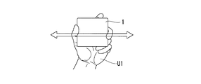
- FIG. 2A shows a linear motion that is a first motion (first motion) determined by the electronic device 1.
- This linear motion is a motion in which the user U1 holds the electronic device 1 and moves linearly between two points.
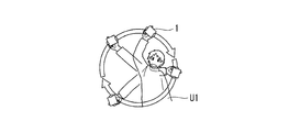
- FIG. 2B shows a circular motion (rotational motion) that is a second motion (second motion) determined by the electronic device 1.
- the circular motion (rotational motion) is a motion in which the user U1 grips the electronic device 1 and draws a circle in a round.
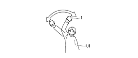
- FIG. 2C shows a circular motion (reciprocating motion) that is a third motion (third motion) determined by the electronic device 1.
- the arc motion (reciprocating motion) is a motion in which the user U1 holds the electronic device 1 and moves, for example, a movement range (operation range) from 30 degrees to 90 degrees in an arc shape.
- FIG. 3 is a block diagram showing the electronic apparatus 1 in the present embodiment.
- the electronic device 1 includes a sensor unit 10, a display unit 20, an operation unit 30, a storage unit 40, and a control unit 50.
- the sensor unit 10 measures displacement information of the own device (main body) for detecting the movement of the own device (main body) as detection data.
- the sensor unit 10 includes an acceleration sensor 11 that detects acceleration data and a gyro sensor 12 that detects angular velocity data.
- the displacement information of the device (main body) includes, for example, acceleration data and angular velocity data.
- the acceleration sensor 11 is, for example, a three-axis acceleration sensor that detects acceleration (acceleration data) in three axes orthogonal to each other (for example, the X axis, the Y axis, and the Z axis).
- the display surface of the display unit 20 is an XY plane, and directions orthogonal to the XY plane are an X direction and a Y direction, respectively. A direction perpendicular to the XY plane is taken as a Z direction.
- the acceleration sensor 11 periodically detects acceleration data at a predetermined sampling cycle (predetermined detection interval), and each acceleration data detected periodically is used as displacement information (detection data) of the control unit 50. Output to.
- the gyro sensor 12 (angular velocity sensor) is, for example, a triaxial angular velocity sensor that detects angular velocities (angular velocity data) in three axes orthogonal to each other (for example, the X axis, the Y axis, and the Z axis).
- the gyro sensor 12 periodically detects angular velocity data at a predetermined sampling cycle (predetermined detection interval), and outputs each angular velocity data detected periodically to the control unit 50 as displacement information (detection data) of the device itself. To do.
- Display unit 20 displays images such as still images and moving images.
- the display unit 20 for example, a liquid crystal display panel, an organic EL (Electro-Luminescence) panel, or the like is used.
- the operation unit 30 is an input unit such as a touch panel or a key switch, and accepts an operation from the user.
- the storage unit 40 stores primary storage data for executing each function of the electronic device 1.
- the storage unit 40 stores, for example, acceleration data and angular velocity data detected by the sensor unit 10 via the control unit 50.
- storage part 40 memorize
- the control unit 50 is, for example, a CPU (Central Processing Unit) and controls each unit of the electronic device 1 in an integrated manner.
- the control unit 50 includes a stillness determination unit 51, a gravity calculation unit 52, a gravity correction unit 53, a locus generation unit 54, a simplification processing unit 55, and a motion determination unit 60.
- the stationary determination unit 51 determines whether or not the stationary state is based on the standard deviation of the angular velocity data detected by the gyro sensor 12, but the acceleration sensor 11 detects it. Based on the standard deviation of the acceleration data, it may be determined whether or not the vehicle is in a stationary state.
- the stationary determination unit 51 determines that the own device (main body) is stationary based on a change in standard deviation with respect to displacement information (eg, angular velocity data) of the own device (main body) for a predetermined number of detection times detected by the sensor unit 10. It is determined whether or not it is in a state.
- displacement information eg, angular velocity data
- the stillness determination unit 51 calculates a standard deviation for each detection point of the angular velocity data based on, for example, 10 angular velocity data of the angular velocity data at the detection point and the past 9 angular velocity data.
- the change of the standard deviation is a graph as shown in FIG.
- the detection point is one (one point) of a plurality of detection data detected by the sensor unit 10 (acceleration sensor 11 and gyro sensor 12) at a predetermined sampling cycle (predetermined detection interval). That is.
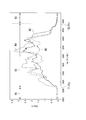
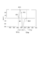
- FIG. 4 is a diagram showing a change in standard deviation of angular velocity data of circular motion (rotational motion) in the present embodiment.
- the horizontal axis indicates time (ms (milliseconds)), and the vertical axis indicates the standard deviation (deg (degree) / s) of angular velocity data.
- a waveform W1 indicates the standard deviation of angular velocity data in the X-axis direction.
- a waveform W2 indicates a standard deviation of angular velocity data in the Y-axis direction.
- a waveform W3 indicates a standard deviation of angular velocity data in the Z-axis direction.
- Time T1 indicates the starting point P S of the motion of the electronic device 1 (Operation of user U1).
- Time T2 indicates the end point P E of the motion of the electronic device 1 (Operation of user U1).
- “movement of the electronic device 1 (self apparatus, main body)” is a dynamic movement (movement) in space.
- the stationary determination unit 51 is stationary when the standard deviations of the angular velocity data in all the axial directions out of the standard deviations of the angular velocity data in the X-axis, Y-axis, and Z-axis directions are equal to or less than a predetermined threshold (first threshold). It is determined that it is in a state.
- the stationary determination unit 51 moves when the standard deviation of the angular velocity data in at least one axial direction among the standard deviations of the angular velocity data in the X-axis, Y-axis, and Z-axis directions is larger than a predetermined threshold (first threshold). It is determined that (in operation). For example, in FIG. 4, the stillness determination unit 51 determines that the period R1 and the period R3 are in a stationary state, and determines that the period R2 is in a moving state (in operation).
- the gravity calculation unit 52 calculates a gravity component (gravity acceleration) included in the acceleration data detected by the acceleration sensor 11. For example, the gravity calculation unit 52 determines the start of movement of the own device (main body) based on the determination result determined by the stillness determination unit 51. In other words, gravity calculating section 52 determines the starting point P S of operation shown in FIG. Further, the acceleration data at the start point P S of this operation, here, the first acceleration data. The gravity calculation unit 52 calculates a gravity component (gravity acceleration) at each detection point based on the first acceleration data using the following equation (1).
- the angular velocity data value is the value of the angular velocity data detected by the gyro sensor 12 at each detection point, and indicates the direction in which the electronic device 1 is moving (the degree of inclination of the electronic device 1 after starting to move).
- the gravity calculation unit 52 is based on acceleration data (first acceleration data) at the start of movement and angular velocity data during the movement of the device detected by the gyro sensor 12.
- the gravity component (gravity acceleration) is calculated. That is, the gravity calculation unit 52 calculates the gravity component (gravity acceleration) at each detection point in consideration of the change in the direction due to the movement of the electronic device 1 according to the equation (1).
- the gravity calculation unit 52 determines the start of the movement of the own device (main body) based on the determination result determined by the stillness determination unit 51, and the motion of the acceleration data detected by the acceleration sensor 11. Based on the first acceleration data which is the acceleration data at the start, the gravity component is calculated.
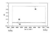
- 5A and 5B are diagrams illustrating an example of comparison between a change in gravity component calculated by the gravity calculation unit 52 and a change in gravity component when a low-pass filter is used.
- the graph shown in FIG. 5A shows a change in the gravity component calculated by the gravity calculation unit 52 when the electronic device 1 is circularly moved by the user U1.
- the graph shown in FIG. 5B shows changes in the gravity component calculated using a low-pass filter as in the background art.
- the horizontal axis indicates time (ms (milliseconds))
- the vertical axis indicates gravity component (gravity acceleration) (G).
- a waveform W4 indicates the gravity component in the X-axis direction calculated by the gravity calculation unit 52 using the equation (1).
- a waveform W5 represents the gravity component in the Y-axis direction calculated by the gravity calculation unit 52 using the equation (1).
- a waveform W6 represents the gravity component in the Z-axis direction calculated by the gravity calculation unit 52 using the equation (1).
- Time T3 represents the starting point P S of the motion of the electronic device 1 (Operation of user U1).
- Time T4 shows the end point P E of the motion of the electronic device 1 (Operation of user U1).
- a waveform W7, a waveform W8, and a waveform W9 indicate gravity components corresponding to the X axis, the Y axis, and the Z axis when calculated using a low-pass filter.
- the gravity calculation unit 52 in the present embodiment can obtain an accurate gravity component as compared with the case where the low-pass filter of FIG. 5B is used.
- the gravity correction unit (correction unit) 53 calculates the gravity component calculated by the gravity calculation unit 52 from the second acceleration data, which is acceleration data detected by the acceleration sensor 11 while the apparatus (main body) is moving (moving state). Correct based on For example, the gravity correction unit 53 calculates, for each detection point, gravity removal acceleration data, which is second acceleration data corrected by removing the gravity component based on the following equation (2).
- the gravity correction unit 53 calculates the gravity removal acceleration data by subtracting the gravity component from the acceleration data (second acceleration data) when the user U1 is operating (the device is moving). As a result, the gravity correction unit 53 generates acceleration data that depends only on the movement of the electronic device 1.
- the trajectory generation unit 54 generates a trajectory of movement of the own device (the electronic device 1, the main body) based on the integration of the second-order integral value of the second acceleration data (gravity removal acceleration data) corrected by the gravity correction unit 53. To do.
- the trajectory generation unit 54 calculates a movement distance by integrating the second-order integral value of the gravity removal acceleration data, and generates, for example, a trajectory of movement on a two-dimensional plane (see FIG. 6A described later).
- the simplification processing unit 55 simplifies the trajectory generated by the trajectory generation unit 54 by changing the trajectory to a predetermined number of different straight lines.
- the simplification processing unit 55 performs the following two-step simplification processing. That is, the simplification processing unit 55 uses a predetermined number (for example, eight) of the first simplification process that is simplified by changing the curve of the trajectory to a straight line and the trajectory simplified by the first simplification process. ) Is changed to a straight line in the moving direction, and a second simplification process is further performed.
- FIG. 6A, 6B, and 6C are diagrams illustrating an example of a locus simplification process in the present embodiment.
- 6A, 6B, and 6C each graph shows, for example, a locus on the XY plane, and the vertical axis and the horizontal axis show the movement distance (m) on each axis.
- a trajectory K1 in FIG. 6A indicates a trajectory generated by the trajectory generation unit 54 and indicates a trajectory before the simplification processing by the simplification processing unit 55 is performed.
- a trajectory K2 in FIG. 6B indicates a trajectory simplified by the simplification processing unit 55 executing a first simplification process to be described later.
- a trajectory K3 in FIG. 6C indicates a trajectory simplified by the simplification processing unit 55 executing a second simplification process described later.
- the simplification processing unit 55 simplifies the locus K1 in FIG. 6A to the locus K2 in FIG. 6B by changing the curve of the locus to a straight line.
- the first simplification process by the simplification processing unit 55 will be described in detail with reference to FIG.
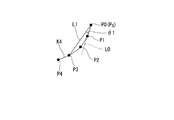
- FIG. 7 is a diagram for explaining the first simplification process of the trajectory in the present embodiment.
- a trajectory K4 is a trajectory generated by the trajectory generator 54, and points P0 to P4 are points on the trajectory corresponding to each detection point.
- a point P0 represents the starting point P S of the movement of the electronic device 1.
- the simplification processing unit 55 executes the following processing in the first simplification processing.
- the simplification processing unit 55 sets the start point P0 (P S ) of the trajectory K4 generated by the trajectory generation unit 54 as the first reference point (setting process).
- the simplification processing unit 55 sets a reference straight line L0 indicating a straight line from the reference point P0 to the next point P1 of the trajectory data.
- the simplification processing unit 55 draws a straight line in order from the reference point P0 to the points P2, P3,... Of the trajectory data, and the angle ⁇ 1 of the straight line with respect to the reference straight line L0 is within a predetermined angle range (for example, ⁇ 30 degrees). Judge lines that exceed (range).
- the simplification processing unit 55 selects a point on the locus where the straight line with the reference point P0 exceeds a predetermined angular range (for example, a range of ⁇ 30 degrees) on the two-dimensional plane with respect to the set reference straight line L0. Then, the order of the trajectory is determined (determination process). In the example shown in FIG. 7, a point on the trajectory exceeding a predetermined angle range corresponds to the point P3. The simplification processing unit 55 changes the trajectory to a straight line L1 from the reference point to the point P3 on the trajectory exceeding a predetermined angle range (change processing).
- a predetermined angular range for example, a range of ⁇ 30 degrees
- the simplification processing unit 55 repeats the same processing (the above-described determination processing and change processing) up to the end point of the trajectory (repetition processing) using the point P3 on the trajectory exceeding the predetermined angle range as the next reference point.
- the simplification processing unit 55 changes the trajectory simplified by the first simplification process in the second simplification process to, for example, eight straight lines in the movement direction, whereby the trajectory of FIG. 6B is obtained. Simplify from K2 to the locus K3 in FIG. 6C.
- the simplification processing unit 55 divides the movement direction into eight parts (for example, when one round of the circular motion is set to 360 degrees, it is divided into 45 parts divided into eight parts). By assigning the divided straight lines in the moving direction to the locus K2, a further simplified locus K3 is generated.
- the movement determination unit 60 determines the movement of the own device (main body) based on the locus simplified by the simplification processing unit 55. That is, the motion determination unit 60 determines the motion of the own device (the operation of the user U1) based on the trajectory generated by the trajectory generation unit 54.
- the motion determination unit 60 includes a trajectory determination unit 61.
- the locus determination unit 61 of the movement determination unit 60 determines, for example, two movements (movements), that is, a linear movement and a circular movement (rotational movement).
- the trajectory determination unit 61 determines that the movement is a linear motion when the trajectory generated by the trajectory generation unit 54 is a movement in one direction.
- the trajectory determination unit 61 has a linear shape in which the trajectory K5 simplified by the simplification processing unit 55 is a predetermined length (predetermined first length) or more and in one direction.
- the motion (motion) of the own device is a linear motion.
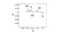
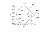
- 8A and 8B are diagrams illustrating an example of motion determination based on a trajectory in the present embodiment. 8A and 8B, each graph shows a locus on the XY plane, for example, as in FIGS. 6A, 6B, and 6C, and the vertical axis and the horizontal axis show the movement distance (m) in each axis. Yes.
- FIG. 8A shows an example in the case of determining a linear motion
- a locus K5 shows an example of a locus simplified by the simplification processing unit 55.
- the trajectory determination unit 61 determines a linear movement.
- the straight line K52 in the trajectory K5 is less than a predetermined length (predetermined first length), and thus is not counted as the direction of movement.
- the trajectory determination unit 61 determines that the trajectory K5 is movement in one direction along the straight line K51, and as a result, determines that the trajectory is linear motion.
- the trajectory determination unit 61 is a straight line having a different moving direction among a predetermined number (for example, eight) of moving directions between the start point and the end point of the trajectory simplified by the simplification processing unit 55. However, when a predetermined number of directions (for example, seven directions) continue in a predetermined order, it is determined that the movement is a circular motion. That is, the trajectory determination unit 61 includes a predetermined number (for example, eight) of straight lines having a predetermined length (predetermined second length) or more between the start point and the end point of the simplified trajectory. If the movement continues for a predetermined number of times (for example, 7 times) or more in different movement directions, it is determined that the movement of the device is a circular movement.
- FIG. 8B shows an example in the case of determining the circular motion
- the locus K3 shows an example of the locus simplified by the simplification processing unit 55.
- the locus determination unit 61 the trajectory K3 from the start point P S to the end point P E, a predetermined length (second length given) or more straight lines, for example, continuous or 7 times If this continues (in this example, straight lines K31 to K38 are continuous), it is determined that the movement of the device is a circular motion.
- the straight line K39 in the trajectory K3 is less than a predetermined length (predetermined second length), and thus is not counted as the direction of movement.
- the predetermined first length and the predetermined second length described above may have different values or the same value.
- the locus determination unit 61 performs the gravity removal. Based on the acceleration data, the movement of the device itself is determined. As described above, the movement determination unit 60 determines the movement of the own apparatus (main body) based on the second acceleration data (gravity removal acceleration data) corrected by the gravity correction unit 53.
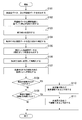
- FIG. 9 is a flowchart illustrating a process of motion determination of the electronic device 1 in the present embodiment.
- the sensor unit 10 detects acceleration data and angular velocity data (step S101).
- the acceleration sensor 11 of the sensor unit 10 periodically detects acceleration data at a predetermined sampling cycle (predetermined detection interval), and outputs each detected acceleration data to the control unit 50 as detection data.
- the gyro sensor 12 of the sensor unit 10 periodically detects angular velocity data at a predetermined sampling period (predetermined detection interval), and outputs each detected angular velocity data to the control unit 50 as detection data.
- the control unit 50 stores the detection data acquired from the sensor unit 10 in the storage unit 40.
- the stationary determination unit 51 of the control unit 50 determines the stationary state based on the standard deviation of the angular velocity data (step S102). For example, the stillness determination unit 51 calculates the standard deviation based on the angular velocity data stored in the storage unit 40. The stationary determination unit 51 determines whether the electronic device 1 is in a stationary state (the operation of the user U1 is stationary) or a moving state (the user U1 is operating) based on the calculated change in standard deviation. judge.
- the gravity calculation unit 52 calculates a gravity component (gravity acceleration) included in the acceleration data detected by the acceleration sensor 11 (step S103). For example, the gravity calculation unit 52 determines the start of the movement of the device (the start point of the operation) based on the determination result determined by the stillness determination unit 51. Further, the gravity calculation unit 52 calculates the gravity component (gravity acceleration) at each detection point based on the acceleration data (first acceleration data) and the angular velocity data at the start point using the above-described equation (1). .
- the gravity correction unit 53 corrects the acceleration data during operation (moving state) detected by the acceleration sensor 11 with the gravity component (step S104). For example, the gravity correction unit 53 corrects the second acceleration data, which is acceleration data while the apparatus is moving (moving state), based on the gravity component calculated by the gravity calculation unit 52. For example, the gravity correction unit 53 calculates gravity removal acceleration data, which is second acceleration data corrected by removing the gravity component based on the above-described equation (2), for each detection point.
- the trajectory generation unit 54 performs second-order integration of the corrected acceleration data to generate a trajectory (step S105). That is, the trajectory generation unit 54 is based on the integration of the second-order integral value of the second acceleration data (gravity removal acceleration data) corrected by the gravity correction unit 53, as shown in FIG. Generate a trajectory of movement.
- the simplification processing unit 55 simplifies the trajectory by changing it to a straight line (step S106). That is, the simplification processing unit 55 converts the trajectory generated by the trajectory generation unit 54 (for example, the trajectory K1 in FIG. 6A) into a simplified trajectory (for example, the trajectory K2 in FIG. 6B) by the first simplification process described above. ).
- the simplification processing unit 55 simplifies the locus into straight lines in the eight movement directions (step S107). That is, the simplification processing unit 55 further simplifies the trajectory (for example, FIG. 6B) obtained by further simplifying the trajectory simplified by the first simplification process (for example, the trajectory K2 in FIG. 6B) by the above-described second simplification processing. 6C trajectory K3).
- the trajectory determining unit 61 of the motion determining unit 60 determines whether or not the moving direction of the trajectory is one direction (step S108). That is, the trajectory determination unit 61 determines whether or not the trajectory simplified by the simplification processing unit 55 is movement in one direction by a straight line having a predetermined length (predetermined first length) or more. .
- the trajectory determining unit 61 advances the process to step S110 when the trajectory is movement in one direction by a straight line having a predetermined length (predetermined first length) or more (step S108: YES). Further, the trajectory determining unit 61 advances the process to step S109 when the trajectory is not moving in one direction by a straight line having a predetermined length (predetermined first length) or more (step S108: NO).
- step S110 the trajectory determination unit 61 determines that the movement (movement) of the own apparatus is a straight line mobility, and ends the movement determination process.
- step S109 the trajectory determination unit 61 determines whether the trajectory continues in seven movement directions. For example, the trajectory determination unit 61 has a straight line longer than a predetermined length (predetermined second length) between the start point and the end point of the simplified trajectory, out of eight movement directions. It is determined whether it has continued seven times or more continuously according to different moving directions.
- the trajectory determining unit 61 advances the process to step S111 when the straight line having the predetermined length or more continues continuously seven times or more in different moving directions (step S109: YES). Further, the trajectory determination unit 61 ends the motion determination process when the straight line having the predetermined length or longer does not continue seven times or more continuously in different moving directions (step S109: NO).
- step S111 the trajectory determination unit 61 determines that the movement of the own device is a circular motion, and ends the movement determination process.
- the electronic device 1 uses the determination result determined by the motion determination processing from step S101 to step S111 in FIG. 9 as a motion interface, and executes various processes of the electronic device 1 based on the determination result.
- the electronic device 1 includes the sensor unit 10, the stationary determination unit 51, the gravity calculation unit 52, the gravity correction unit 53, and the motion determination unit 60.
- the sensor unit 10 detects displacement information of the own device (main body) including at least acceleration data. Whether the own device (main body) is in a stationary state based on a change in standard deviation with respect to displacement information (detection data) of the own device (main body) for a predetermined number of detection times detected by the sensor unit 10. Determine whether or not.
- the gravity calculation unit 52 determines the start of the movement of the own device (main body) based on the determination result determined by the stillness determination unit 51, and the acceleration data at the start of the movement among the acceleration data detected by the sensor unit 10.
- the gravity component is calculated based on the first acceleration data.
- the gravity correction unit 53 corrects the second acceleration data, which is acceleration data detected by the sensor unit 10 while the device (main body) is moving, based on the gravity component calculated by the gravity calculation unit 52.
- the determination unit 60 determines the movement based on the second acceleration data corrected by the gravity correction unit 53.
- the electronic apparatus 1 in the present embodiment can calculate the gravity component more accurately than in the case where a conventional low-pass filter is used (FIG. 5B). Therefore, the electronic device 1 in the present embodiment can accurately detect acceleration data based on the movement of the device (main body) (the operation of the user U1). Therefore, the electronic device 1 in this embodiment can improve the determination rate of the movement of the own device (main body).
- the sensor unit 10 detects angular velocity data as displacement information of the own device.
- the gravity calculation unit 52 calculates a gravity component (gravity acceleration) based on acceleration data at the start of movement (starting point) and angular velocity data detected by the sensor unit 10 while the device is moving (moving). calculate.
- the electronic device 1 in the present embodiment accurately calculates the gravity component (gravity acceleration). be able to. Therefore, the electronic device 1 in the present embodiment can improve the determination rate of the movement of the own device.
- the stationary determination unit 51 is in a stationary state based on a change in standard deviation with respect to angular velocity data corresponding to a predetermined number of detection times (for example, 10 times) detected by the sensor unit 10 as displacement information of the device itself. Determine.
- the standard deviation of the angular velocity data indicates a variation in the angular velocity data, and the electronic device 1 in the present embodiment can appropriately detect the change in the angular velocity data based on the change in the standard deviation of the angular velocity data. Therefore, the electronic device 1 in the present embodiment can accurately determine the stationary state, and can accurately determine the start point and end point of movement (movement). Therefore, the electronic device 1 in the present embodiment can improve the determination rate of the movement of the own device.
- the stationary determination unit 51 may determine the stationary state based on a change in standard deviation with respect to acceleration data for a predetermined number of detection times detected by the sensor unit 10 as displacement information of the device itself.
- the electronic device 1 in the present embodiment can appropriately capture the change in the acceleration data based on the change in the standard deviation of the acceleration data. Therefore, the electronic device 1 in the present embodiment can accurately determine the stationary state, and can accurately determine the start point and end point of movement (movement).
- the electronic device 1 includes a trajectory generation unit 54 that generates a trajectory of movement of the own device based on the integration of the second-order integral value of the second acceleration data corrected by the gravity correction unit 53. Yes.
- the motion determination unit 60 (trajectory determination unit 61) determines a motion based on the trajectory generated by the trajectory generation unit 54.
- the electronic device 1 in the present embodiment can accurately determine a movement (type of movement (movement)) such as a straight line mobility or a circular movement, for example, based on the trajectory.
- the movement determination unit 60 moves the own apparatus when the locus generated by the locus generation unit 54 is a straight line having a predetermined first length or more and movement in one direction. It is determined that the movement is linear.
- the electronic device 1 in this embodiment can determine linear motion by a simple means.
- the electronic device 1 includes a simplification processing unit 55 that simplifies the trajectory generated by the trajectory generation unit 54 by changing the trajectory generated by the predetermined number (e.g., eight) of movement directions to straight lines.
- the motion determination unit 60 performs a predetermined number of times (for example, 7 times) in different movement directions among a predetermined number of movement directions between the start point and the end point of the trajectory simplified by the simplification processing unit 55.
- a predetermined number of times for example, 7 times
- the simplification processing unit 55 uses a predetermined number of first simplification processes that are simplified by changing the curve of the trajectory to a straight line, and a trajectory simplified by the first simplification process.
- a second simplification process that further simplifies by changing to a straight line in the moving direction (e.g., 8) is executed.
- the first simplification process includes a setting process for setting the start point of the trajectory generated by the trajectory generation unit 54 as the first reference point, a determination process, a change process, a determination process, and a trajectory exceeding a predetermined angle range. It includes a repeat process that repeats the change process up to the end point of the trajectory with the upper point as the next reference point.
- the determination process sets a reference line indicating a straight line from the reference point to the next point in the trajectory, and the straight line with the reference point has a predetermined angular range on the two-dimensional plane with respect to the set reference line. Points that exceed the trajectory are determined in the trajectory order.
- the locus is changed to a straight line from the reference point to a point on the locus exceeding a predetermined angle range.
- the electronic device 1 in this embodiment can simplify the locus
- FIG. 10 is a block diagram showing an electronic apparatus (main body) 1a according to this embodiment.
- the electronic device 1a determines the linear motion (FIG. 2A) and the circular motion (FIG. 2B) described above and the circular motion (FIG. 2C) described above.
- the electronic device 1a includes a sensor unit 10, a display unit 20, an operation unit 30, a storage unit 40, and a control unit 50a.
- the same components as those in FIG. 3 are denoted by the same reference numerals, and the description thereof is omitted.
- the control unit 50a includes a start / end determination unit 56 and an arc motion determination unit 62, and the control unit 50a is different from the first embodiment in that the control unit 50a determines an arc motion.
- the control unit 50a controls the respective units of the electronic device 1a in an integrated manner, similarly to the control unit 50 in the first embodiment.
- the control unit 50a includes a stillness determination unit 51, a gravity calculation unit 52, a gravity correction unit 53, a locus generation unit 54, a simplification processing unit 55, a start / end determination unit 56, and a motion determination unit 60a.
- the motion determination unit 60 a includes a trajectory determination unit 61 and an arc motion determination unit 62.
- the start / end determination unit 56 and the movement end point P S are detected.
- a point P E is determined.
- the start / end determination unit 56 reverses the direction of displacement of the own device (main body) based on the determination result (result of whether or not the stationary state is determined) determined by the stationary determination unit 51 and the angular velocity data ( The intermediate point P M (time T6 in FIG. 11) is determined (the sign of the angular velocity data is inverted).
- Start end determining unit 56 determines, for example, the angular velocity data is within a predetermined range (predetermined threshold range), and, if the motion is continued, as the intermediate point P M.
- a predetermined range predetermined threshold range
- determination quiescence determining unit 51 determines the result, and on the basis of the angular velocity data gyro sensor 12 detects and determines movement of the starting point P S and the motion of the end point P E together, it determines the midpoint P M positive and negative values of the angular velocity data is inverted.
- FIG. 11 is a diagram illustrating an example of angular velocity data in an arc motion (reciprocating motion).
- the horizontal axis represents time (ms (milliseconds)), and the vertical axis represents angular velocity data (deg (degrees) / s).
- a waveform W10 indicates angular velocity data in the X-axis direction.
- a waveform W11 indicates angular velocity data in the Y-axis direction.
- a waveform W12 indicates angular velocity data in the Z-axis direction.
- Time T5 indicates the starting point P S of the motion of the electronic device 1a.
- Time T6 shows the intermediate point P M of motion of an electronic device 1a.
- Time T7 indicates the end point P E of the motion of the electronic device 1a.
- the waveform W121 indicates the angular velocity data from the start point P S to the intermediate point P M.
- the waveform W122 indicates the angular velocity data from the intermediate point P M to the end point P E.
- the start / end determination unit 56 outputs the determined start point P S , intermediate point P M , and end point P E (for example, information on time T5, time T6, and time T7) to the motion determination unit 60a.
- the arc motion determination unit 62 of the motion determination unit 60a includes an angular displacement amount obtained by integrating angular velocity data from the motion start point P S (time T5) to the intermediate point P M (time T6), and the intermediate point P M (time). angular velocity data from T6) to the movement of the end point P E (time T7) to calculate the amount of displacement of the integrated angle.
- the arcuate movement determining unit 62 displacement of the integrated angle angular velocity data from the start point P S of the motion to the intermediate point P M (e.g., + side) is the predetermined threshold value (second threshold value) or more And the displacement of the angle obtained by integrating the angular velocity data from the intermediate point P M to the movement end point P E (for example, the ⁇ side) is equal to or larger than a predetermined threshold (third threshold). It is determined that the movement of the (main body) is an arc movement.
- the predetermined threshold value determining the displacement of the angle from the start point P S of the motion to the intermediate point P M (second threshold value), the displacement angle from the start point P M of the motion to the intermediate point P E
- the predetermined threshold value (third threshold value) for determining the amount is, for example, 30 degrees.
- the arc motion determination unit 62 performs a motion (motion) in which the direction of motion is one set on the + side and the ⁇ side with a displacement amount of an angle equal to or greater than a predetermined threshold (for example, ⁇ 30 degrees).
- a predetermined threshold for example, ⁇ 30 degrees.
- FIG. 12 is a flowchart showing a process of motion determination of the electronic device 1a in the present embodiment.
- the processing from step S201 to step S211 is the same as the processing from step S101 to step S111 of FIG. 9, and the description thereof is omitted here.
- the trajectory determination unit 61 determines that the straight line longer than the predetermined length does not continue seven or more times continuously in different moving directions (step S210: NO). Then, the process proceeds to step S212.
- step S212 the start / end determination unit 56 determines the start point P S , the intermediate point P M , and the end point P E. That is, for example, when the angular velocity data detected by the gyro sensor 12 exceeds a predetermined range (predetermined threshold range), the start / end determination unit 56 determines the movement start point P S (time T5 in FIG. 11) and the movement. End point P E (time T7 in FIG. 11) is determined.
- the start / end determination unit 56 is, for example, an intermediate point where the sign of the angular velocity data is reversed based on the determination result (result of whether or not the stationary state is determined) determined by the stationary determination unit 51 and the angular velocity data.
- P M time T6 in FIG. 11
- the arc motion determination unit 62 of the motion determination unit 60a integrates angular velocity data from the motion start point P S (time T5 in FIG. 11) to the intermediate point P M (time T6 in FIG. 11). The amount is calculated (step S213). Further, the arc motion determination unit 62 calculates an angular displacement obtained by integrating the angular velocity data from the intermediate point P M (time T6 in FIG. 11) to the movement end point P E (time T7 in FIG. 11) (step). S214).
- the arc motion determination unit 62 determines whether or not the displacement amount of the two angles is greater than or equal to a predetermined threshold (for example, 30 degrees) (step S215).
- a predetermined threshold for example, 30 degrees
- arcuate movement determining unit 62 displacement of the angle from the start point P S of the motion to the intermediate point P M (e.g., + side) of a predetermined threshold value (e.g., 30 degrees) or more, and the midpoint displacement angle from P M to the end point P E motion (e.g., - side) is equal to or a predetermined threshold (e.g., 30 degrees) or more.
- step S215: YES When the displacement amount of the two angles is equal to or greater than a predetermined threshold (for example, 30 degrees) (step S215: YES), the arc motion determination unit 62 proceeds with the process to step S216. In addition, the arc motion determination unit 62 ends the process when the displacement amount of the two angles is not equal to or greater than a predetermined threshold (for example, 30 degrees) (step S215: NO).
- a predetermined threshold for example, 30 degrees
- step S216 the arc motion determination unit 62 determines that the movement of the own device is an arc motion, and ends the process. That is, if the arcuate movement determining unit 62, displacement of the angle from the start point P S of the motion to the intermediate point P M (e.g., + side) of a predetermined threshold value (e.g., 30 degrees) is not less than, and the intermediate displacement of the angle from the point P M to the end point P E motion (e.g., - side) of a predetermined threshold value (e.g., 30 degrees) is determined and if it is more than a circular motion the movement of the device itself .
- a predetermined threshold value e.g. 30 degrees
- step S201 to step S216 the motion determination processing by the trajectory determination unit 61 and the motion determination processing by the arc motion determination unit 62 have been described as serial processing (sequential execution processing). It may be processed as parallel processing (parallel execution processing).
- the determination result of the still determination unit 51 determines, and on the basis of the angular velocity data gyro sensor 12 detects the starting point of the motion P S and the end point of the movement P with determining E, the direction of displacement of the device itself (body) is provided with a start end determining unit 56 determines an intermediate point P M inverted.
- the movement determination unit 60a determines the movement (eg, linear movement, circular movement) of the own apparatus (main body).
- Motion determination section 60a is configured to determine the movement of the corrected self apparatus based on the second acceleration data (body), the amount of displacement of the integrated angle angular velocity data from the start point P S of the motion to the intermediate point P M Is greater than or equal to a predetermined threshold, and when the amount of angular displacement obtained by integrating the angular velocity data from the intermediate point P M to the movement end point P E is greater than or equal to the predetermined threshold, the movement of the device (main body) Is determined to be an arc motion.
- the electronic device 1a in this embodiment can determine circular motion by a simple means.
- the electronic device 1a in the present embodiment is similar to the first embodiment in that the sensor unit 10, the stationary determination unit 51, the gravity calculation unit 52, the gravity correction unit 53, the locus generation unit 54, the simplification processing unit 55, And a trajectory generation unit 54 of the motion determination unit 60a. Therefore, the electronic device 1a in this embodiment has the same effect as that of the first embodiment.
- the present invention is not limited to the above embodiments, and can be modified without departing from the spirit of the present invention.
- the acceleration sensor 11 and the gyro sensor 12 have been described as detecting three axes orthogonal to each other (for example, the X axis, the Y axis, and the Z axis), but the present invention is not limited to this. It is not a thing.
- the control unit 50 (50a) is based on measured values obtained by detecting each axis for a certain period in a stationary state in order to reduce an attachment error of the acceleration sensor 11 and the gyro sensor 12 and individual differences between the sensors. A calibration process for correcting the detection data may be executed.
- the stationary determination unit 51 has been described as determining the stationary state based on the standard deviation of the angular velocity data detected by the gyro sensor 12, but the acceleration data detected by the acceleration sensor 11 may be The stationary state may be determined based on the standard deviation. Stillness determination unit 51 may determine the still state based on both the standard deviation of the angular velocity data and the standard deviation of the acceleration data.
- the simplification processing unit 55 has described the two-step simplification form of the first simplification process and the second simplification process. Either the second simplification process or one of them may be executed.
- the 2nd simplification process demonstrated the form divided
- the electronic device 1 (1a) has been described as detecting a linear motion, a circular motion (rotational motion), or an arc motion (reciprocating motion). It may be detected.
- the operation (operation) by the user U1 is not limited to a gesture for drawing a circle (two-dimensional) or a straight line (one-dimensional), but may be a three-dimensional gesture for drawing a three-dimensional figure.
- each unit included in the control unit 50 (50a) in each of the above embodiments may be realized by dedicated hardware.
- Each unit included in the control unit 50 (50a) is configured by a memory and a CPU, and by loading a program for realizing the function of each unit included in the control unit 50 (50a) into the memory and executing the program, the function is achieved. It may be realized.
- the “computer system” may include an OS and hardware such as peripheral devices.
- the “computer-readable recording medium” means a magnetic disk, a magneto-optical disk, an SD card, a writable nonvolatile memory such as a flash memory, a portable medium such as a CD-ROM, and a hard disk built in a computer system. This means a storage device such as
- the “computer-readable recording medium” refers to a volatile memory (for example, DRAM (in DRAM) in a computer system that becomes a server or a client when a program is transmitted through a network such as the Internet or a communication line such as a telephone line. It may include those that hold a program for a certain period of time, such as Dynamic Random Access Memory)).
- the program may be transmitted from a computer system storing the program in a storage device or the like to another computer system via a transmission medium or by a transmission wave in the transmission medium.
- the “transmission medium” for transmitting the program refers to a medium having a function of transmitting information, such as a network (communication network) such as the Internet or a communication line (communication line) such as a telephone line.
- the program may be for realizing a part of the functions described above. Furthermore, what can implement
Landscapes
- Engineering & Computer Science (AREA)
- Physics & Mathematics (AREA)
- General Physics & Mathematics (AREA)
- General Engineering & Computer Science (AREA)
- Theoretical Computer Science (AREA)
- Human Computer Interaction (AREA)
- User Interface Of Digital Computer (AREA)
- Indicating Or Recording The Presence, Absence, Or Direction Of Movement (AREA)
- Telephone Function (AREA)
Abstract
電子機器は、少なくとも加速度データを含む本体の変位情報を検出するセンサ部と、センサ部が検出した所定の検出回数分の変位情報に対する標準偏差の変化に基づいて、本体が静止状態であるか否かを判定する静止判定部と、静止判定部が判定した判定結果に基づいて本体の動きの開始を判定し、センサ部によって検出された加速度データのうちの、動きの開始における加速度データである第1加速度データに基づいて、重力成分を算出する重力算出部と、本体が動いている間にセンサ部が検出した加速度データである第2加速度データを、重力算出部が算出した重力成分に基づいて補正する補正部と、補正部によって補正された第2加速度データに基づいて、動きを判定する動き判定部とを備える。
Description
本発明は、電子機器、及びプログラムに関する。
本願は、2012年9月19日に出願された特願2012-206310号に基づき優先権を主張し、その内容をここに援用する。
本願は、2012年9月19日に出願された特願2012-206310号に基づき優先権を主張し、その内容をここに援用する。
近年、電子機器において、モーション判定などの動き判定を行う技術が知られている(例えば、特許文献1を参照)。例えば、特許文献1の技術では、電子機器は、加速度検出手段が検出した加速度データを、ローパスフィルタ処理して得られた静止成分(重力成分)と、動き成分とに分離している。ここで、動き成分は、加速度検出手段が検出した加速度成分データから上述の静止成分(重力成分)を除いて生成している。特許文献1に記載の電子機器は、静止成分(重力成分)を除いた動き成分に基づいて、自装置(自己の電子機器、本体)の動きを判定している。
しかしながら、上述したような電子機器は、ローパスフィルタ処理して得られた静止成分(重力成分)に基づいているため、静止成分(重力成分)が正確に得られずに、動き成分が正しく分離できない場合がある。そのため、例えば、直線運動や円運動などの動きを正しく判定できない場合がある。
本発明の態様は、自装置(本体)の動きの判定率を向上させることができる電子機器、及びプログラムを提供することを目的とする。
本発明の一態様に係る電子機器は、少なくとも加速度データを含む本体の変位情報を検出するセンサ部と、前記センサ部が検出した所定の検出回数分の前記変位情報に対する標準偏差の変化に基づいて、本体が静止状態であるか否かを判定する静止判定部と、前記静止判定部が判定した判定結果に基づいて前記本体の動きの開始を判定し、前記センサ部によって検出された加速度データのうちの、前記動きの開始における加速度データである第1加速度データに基づいて、重力成分を算出する重力算出部と、前記本体が動いている間に前記センサ部が検出した加速度データである第2加速度データを、前記重力算出部が算出した前記重力成分に基づいて補正する補正部と、前記補正部によって補正された前記第2加速度データに基づいて、前記動きを判定する動き判定部とを備える。
また、本発明の他の態様に係るプログラムは、コンピュータに、静止判定部が、少なくとも加速度データを含む本体の変位情報を検出するセンサ部によって検出された所定の検出回数分の前記変位情報に対する標準偏差の変化に基づいて、本体が静止状態であるか否かを判定する静止判定手順と、重力算出部が、前記静止判定手順によって判定された判定結果に基づいて前記本体の動きの開始を判定し、前記センサ部によって検出された加速度データのうちの、前記動きの開始における加速度データである第1加速度データに基づいて、重力成分を算出する重力成分算出手順と、補正部が、前記本体が動いている間に前記センサ部が検出した加速度データである第2加速度データを、前記重力算出部が算出した前記重力成分に基づいて補正する補正手順と、動き判定部が、前記補正手順によって補正された前記第2加速度データに基づいて、前記動きを判定する動き判定手順と、を実行させる。
本発明の態様によれば、自装置(本体)の動きの判定率を向上させることができる。
以下、本発明の一実施形態による電子機器(本体)1について図面を参照して説明する。
図1は、本実施形態による電子機器1の外観の一例を示す概観図である。
電子機器1は、図1に示すように、前面部に表示部20を備えている。
電子機器1は、使用者が手に持って移動させた場合に、自装置(自己の電子機器、本体)の動きを判定することで、自装置の動きをインターフェースとして利用するモーションインターフェースを有している。すなわち、電子機器1は、自装置の動きを判定(検出)することにより、使用者の動作(モーション、ジェスチャー)を判定(検出)する。電子機器1は、例えば、携帯電話機、スマートフォン、デジタルカメラ等の携帯情報端末である。
なお、本実施形態における電子機器1は、例えば、図2A、2B、2Cに示すような3種類の動きを判定する。ここで、電子機器1が判定する3種類の動きについて説明する。
図2Aは、電子機器1が判定する第1の動き(第1の運動)である直線運動を示している。この直線運動は、使用者U1が電子機器1を把持して、2点間を直線的に移動させる運動である。
また、図2Bは、電子機器1が判定する第2の動き(第2の運動)である円運動(回転運動)を示している。円運動(回転運動)は、使用者U1が電子機器1を把持して、円形を描いて1周させる運動である。
また、図2Cは、電子機器1が判定する第3の動き(第3の運動)である円弧運動(往復運動)を示している。円弧運動(往復運動)は、使用者U1が電子機器1を把持して、例えば、30度から90度の移動範囲(動作範囲)を円弧状に移動させる運動である。
また、図2Bは、電子機器1が判定する第2の動き(第2の運動)である円運動(回転運動)を示している。円運動(回転運動)は、使用者U1が電子機器1を把持して、円形を描いて1周させる運動である。
また、図2Cは、電子機器1が判定する第3の動き(第3の運動)である円弧運動(往復運動)を示している。円弧運動(往復運動)は、使用者U1が電子機器1を把持して、例えば、30度から90度の移動範囲(動作範囲)を円弧状に移動させる運動である。
[第1の実施形態]
次に、本発明に係る第1の実施形態について説明する。
第1の実施形態では、電子機器1が、上述した直線運動(図2A)と、円運動(図2B)とを判定する一例について説明する。
次に、本発明に係る第1の実施形態について説明する。
第1の実施形態では、電子機器1が、上述した直線運動(図2A)と、円運動(図2B)とを判定する一例について説明する。
まず、図3を参照して、電子機器1の構成について説明する。
図3は、本実施形態における電子機器1を示すブロック図である。
図3において、電子機器1は、センサ部10、表示部20、操作部30、記憶部40、及び制御部50を備えている。
図3は、本実施形態における電子機器1を示すブロック図である。
図3において、電子機器1は、センサ部10、表示部20、操作部30、記憶部40、及び制御部50を備えている。
センサ部10は、自装置(本体)の動きを検出するための自装置(本体)の変位情報を検出データとして測定する。センサ部10は、加速度データを検出する加速度センサ11及び角速度データを検出するジャイロセンサ12を有している。ここで、自装置(本体)の変位情報には、例えば、加速度データと、角速度データとが含まれる。
加速度センサ11は、例えば、互いに直交する3軸(例えば、X軸、Y軸、及びZ軸)それぞれにおける加速度(加速度データ)を検出する3軸加速度センサである。なお、本実施形態では、表示部20の表示面をXY平面とし、XY平面において直交する方向をそれぞれX方向及びY方向とする。また、XY平面に垂直な方向をZ方向とする。
また、加速度センサ11は、所定のサンプリング周期(所定の検出間隔)で周期的に加速度データを検出し、周期的に検出したそれぞれの加速度データを自装置の変位情報(検出データ)として制御部50に出力する。
また、加速度センサ11は、所定のサンプリング周期(所定の検出間隔)で周期的に加速度データを検出し、周期的に検出したそれぞれの加速度データを自装置の変位情報(検出データ)として制御部50に出力する。
ジャイロセンサ12(角速度センサ)は、例えば、互いに直交する3軸(例えば、X軸、Y軸、及びZ軸)それぞれにおける角速度(角速度データ)を検出する3軸角速度センサである。ジャイロセンサ12は、所定のサンプリング周期(所定の検出間隔)で周期的に角速度データを検出し、周期的に検出したそれぞれの角速度データを自装置の変位情報(検出データ)として制御部50に出力する。
表示部20は、静止画や動画などの画像を表示する。表示部20としては、例えば、液晶表示パネルや、有機EL(Electro-Luminescence)パネルなどが用いられる。
操作部30は、例えば、タッチパネルやキースイッチなどの入力部であり、使用者からの操作を受け付ける。
記憶部40は、電子機器1の各機能を実行するための一次記憶データを記憶する。記憶部40は、例えば、制御部50を介して、センサ部10が検出した加速度データ及び角速度データを記憶する。また、記憶部40は、例えば、後述する角速度データの標準偏差や軌跡データなどを記憶する。
制御部50は、例えば、CPU(Central Processing Unit)であり、電子機器1の各部を統括して制御する。制御部50は、静止判定部51、重力算出部52、重力補正部53、軌跡生成部54、簡略化処理部55、及び動き判定部60を備えている。
静止判定部51は、センサ部10のジャイロセンサ12が検出した角速度データの標準偏差の変化に基づいて、電子機器(本体)1が静止状態(使用者U1の動作が静止中)であるか、移動状態(使用者U1が動作中)であるかを判定する。なお、本実施形態では、静止判定部51は、一例として、ジャイロセンサ12が検出した角速度データの標準偏差に基づいて、静止状態であるか否かを判定しているが、加速度センサ11が検出した加速度データの標準偏差に基づいて、静止状態であるか否かを判定してもよい。すなわち、静止判定部51は、センサ部10が検出した所定の検出回数分の自装置(本体)の変位情報(例、角速度データ)に対する標準偏差の変化に基づいて、自装置(本体)が静止状態であるか否かを判定する。
静止判定部51は、角速度データのそれぞれの検出点について、例えば、検出点における角速度データと過去9回の角速度データとの10回分の角速度データに基づいて、標準偏差を算出する。この標準偏差の変化は、図4に示すようなグラフとなる。ここで、検出点とは、センサ部10(加速度センサ11及びジャイロセンサ12)が、所定のサンプリング周期(所定の検出間隔)で検出を行った複数の検出データのうちの1つ(1点)のことである。
図4は、本実施形態における円運動(回転運動)の角速度データの標準偏差の変化を示す図である。
図4のグラフにおいて、横軸は時間(ms(ミリ秒))を示し、縦軸は角速度データの標準偏差(deg(度)/s)を示している。波形W1は、X軸方向の角速度データの標準偏差を示している。波形W2は、Y軸方向の角速度データの標準偏差を示している。波形W3は、Z軸方向の角速度データの標準偏差を示している。時刻T1は、電子機器1の動き(使用者U1の動作)の開始点PSを示している。時刻T2は、電子機器1の動き(使用者U1の動作)の終了点PEを示している。なお、ここで、「電子機器1(自装置、本体)の動き」とは、空間上の力学的な動き(移動)のことである。
図4のグラフにおいて、横軸は時間(ms(ミリ秒))を示し、縦軸は角速度データの標準偏差(deg(度)/s)を示している。波形W1は、X軸方向の角速度データの標準偏差を示している。波形W2は、Y軸方向の角速度データの標準偏差を示している。波形W3は、Z軸方向の角速度データの標準偏差を示している。時刻T1は、電子機器1の動き(使用者U1の動作)の開始点PSを示している。時刻T2は、電子機器1の動き(使用者U1の動作)の終了点PEを示している。なお、ここで、「電子機器1(自装置、本体)の動き」とは、空間上の力学的な動き(移動)のことである。
静止判定部51は、X軸、Y軸、Z軸方向の角速度データの標準偏差のうち、全ての軸方向の角速度データの標準偏差が所定の閾値(第1閾値)以下である場合に、静止状態であると判定する。静止判定部51は、X軸、Y軸、Z軸方向の角速度データの標準偏差のうち、少なくとも1軸方向の角速度データの標準偏差が所定の閾値(第1閾値)より大きい場合に、移動状態(動作中)であると判定する。例えば、図4において、静止判定部51は、期間R1及び期間R3を静止状態であると判定し、期間R2を移動状態(動作中)であると判定する。
重力算出部52は、加速度センサ11が検出した加速度データに含まれる重力成分(重力加速度)を算出する。例えば、重力算出部52は、静止判定部51が判定した判定結果に基づいて自装置(本体)の動きの開始を判定する。つまり、重力算出部52は、図4に示す動作の開始点PSを判定する。また、この動作の開始点PSにおける加速度データを、ここでは、第1加速度データとする。重力算出部52は、下記の式(1)を用いて、第1加速度データに基づいて、各検出点における重力成分(重力加速度)を算出する。
(重力成分)=(第1加速度データ値)×(角速度データ値) ・・・(1)
ここで、角速度データ値は、各検出点において、ジャイロセンサ12が検出した角速度データの値であり、電子機器1の移動中における向き(動き出してからの電子機器1の傾き度合)を示している。重力算出部52は、式(1)に示すように、動きの開始における加速度データ(第1加速度データ)と、ジャイロセンサ12が検出した自装置が動いている間の角速度データとに基づいて、重力成分(重力加速度)を算出する。すなわち、重力算出部52は、式(1)によって、電子機器1の移動による向きの変化を考慮して、各検出点における重力成分(重力加速度)を算出する。
このように、重力算出部52は、静止判定部51が判定した判定結果に基づいて自装置(本体)の動きの開始を判定し、加速度センサ11によって検出された加速度データのうちの、動きの開始における加速度データである第1加速度データに基づいて、重力成分を算出する。
このように、重力算出部52は、静止判定部51が判定した判定結果に基づいて自装置(本体)の動きの開始を判定し、加速度センサ11によって検出された加速度データのうちの、動きの開始における加速度データである第1加速度データに基づいて、重力成分を算出する。
図5A、5Bは、重力算出部52が算出した重力成分の変化と、ローパスフィルタを用いた場合の重力成分の変化との比較の一例を示す図である。
図5Aに示すグラフは、電子機器1が使用者U1によって円運動された場合において、重力算出部52が算出した重力成分の変化を示している。図5Bに示すグラフは、比較のために、背景技術のようにローパスフィルタを用いて算出した重力成分の変化を示している。
図5A、5Bのグラフにおいて、横軸は時間(ms(ミリ秒))を示し、縦軸は重力成分(重力加速度)(G)を示している。
図5Aに示すグラフは、電子機器1が使用者U1によって円運動された場合において、重力算出部52が算出した重力成分の変化を示している。図5Bに示すグラフは、比較のために、背景技術のようにローパスフィルタを用いて算出した重力成分の変化を示している。
図5A、5Bのグラフにおいて、横軸は時間(ms(ミリ秒))を示し、縦軸は重力成分(重力加速度)(G)を示している。
図5Aにおいて、波形W4は、重力算出部52が式(1)を用いて算出したX軸方向の重力成分を示している。波形W5は、重力算出部52が式(1)を用いて算出したY軸方向の重力成分を示している。波形W6は、重力算出部52が式(1)を用いて算出したZ軸方向の重力成分を示している。時刻T3は、電子機器1の動き(使用者U1の動作)の開始点PSを示している。時刻T4は、電子機器1の動き(使用者U1の動作)の終了点PEを示している。
図5Bにおいて、波形W7、波形W8、及び波形W9は、ローパスフィルタを用いて算出した場合における、X軸、Y軸、及びZ軸それぞれに対応する重力成分を示している。
波形W4、波形W5、及びW6に示すように、本実施形態における重力算出部52は、図5Bのローパスフィルタを用いる場合に比べて、正確な重力成分を得ることができる。
図5Bにおいて、波形W7、波形W8、及び波形W9は、ローパスフィルタを用いて算出した場合における、X軸、Y軸、及びZ軸それぞれに対応する重力成分を示している。
波形W4、波形W5、及びW6に示すように、本実施形態における重力算出部52は、図5Bのローパスフィルタを用いる場合に比べて、正確な重力成分を得ることができる。
重力補正部(補正部)53は、自装置(本体)が動いている間(移動状態)に加速度センサ11が検出した加速度データである第2加速度データを、重力算出部52が算出した重力成分に基づいて補正する。重力補正部53は、例えば、下記の式(2)に基づいて重力成分を除去して補正した第2加速度データである重力除去加速度データを検出点ごとに算出する。
(重力除去加速度データ値)=(第2加速度データ値)-(重力成分) ・・・(2)
すなわち、重力補正部53は、使用者U1が動作中(自装置が移動状態)における加速度データ(第2加速度データ)から重力成分を減算することにより、重力除去加速度データを算出する。これにより、重力補正部53は、電子機器1の動きにのみ依存した加速度データを生成する。
軌跡生成部54は、重力補正部53によって補正された第2加速度データ(重力除去加速度データ)の2階積分値の積算に基づいて、自装置(電子機器1、本体)の移動の軌跡を生成する。軌跡生成部54は、重力除去加速度データの2階積分値の積算により、移動距離を算出し、例えば、2次元平面上の移動の軌跡(後述する図6A参照)を生成する。
簡略化処理部55は、軌跡生成部54が生成した軌跡を、互いに異なる所定数の移動方向の直線に変更することにより簡略化する。簡略化処理部55は、例えば、以下の2段階の簡略化処理を行う。すなわち、簡略化処理部55は、軌跡の曲線を直線に変更することにより簡略化する第1の簡略化処理と、第1の簡略化処理によって簡略化した軌跡を、所定数(例えば、8つ)の移動方向の直線に変更することにより、さらに簡略化する第2の簡略化処理を実行する。
図6A、6B、6Cは、本実施形態における軌跡の簡略化処理の一例を示す図である。
図6A、6B、6Cにおいて、各グラフは、例えば、XY平面上の軌跡を示しており、縦軸及び横軸は、各軸における移動距離(m)を示している。
図6Aの軌跡K1は、軌跡生成部54が生成した軌跡を示しており、簡略化処理部55による簡略化処理が行われる前の軌跡を示している。
図6Bの軌跡K2は、後述する第1の簡略化処理を簡略化処理部55が実行することにより、簡略化された軌跡を示している。
図6Cの軌跡K3は、後述する第2の簡略化処理を簡略化処理部55が実行することにより、簡略化された軌跡を示している。
図6A、6B、6Cにおいて、各グラフは、例えば、XY平面上の軌跡を示しており、縦軸及び横軸は、各軸における移動距離(m)を示している。
図6Aの軌跡K1は、軌跡生成部54が生成した軌跡を示しており、簡略化処理部55による簡略化処理が行われる前の軌跡を示している。
図6Bの軌跡K2は、後述する第1の簡略化処理を簡略化処理部55が実行することにより、簡略化された軌跡を示している。
図6Cの軌跡K3は、後述する第2の簡略化処理を簡略化処理部55が実行することにより、簡略化された軌跡を示している。
簡略化処理部55は、第1の簡略化処理において、軌跡の曲線を直線に変更することにより、図6Aの軌跡K1から図6Bの軌跡K2に簡略化する。
ここで、この簡略化処理部55による第1の簡略化処理について、図7を参照して詳細に説明する。
ここで、この簡略化処理部55による第1の簡略化処理について、図7を参照して詳細に説明する。
図7は、本実施形態における軌跡の第1の簡略化処理を説明する図である。
この図において、軌跡K4は、軌跡生成部54が生成した軌跡であり、点P0~点P4は、各検出点に対応する軌跡上の点である。また、点P0は、電子機器1の移動の開始点PSを示している。
簡略化処理部55は、第1の簡略化処理において、以下の処理を実行する。
この図において、軌跡K4は、軌跡生成部54が生成した軌跡であり、点P0~点P4は、各検出点に対応する軌跡上の点である。また、点P0は、電子機器1の移動の開始点PSを示している。
簡略化処理部55は、第1の簡略化処理において、以下の処理を実行する。
簡略化処理部55は、軌跡生成部54が生成した軌跡K4の開始点P0(PS)を最初の基準点に設定する(設定処理)。
簡略化処理部55は、基準点P0から軌跡データの次の点P1までの直線を示す基準直線L0を設定する。簡略化処理部55は、基準点P0から軌跡データの点P2、P3、・・・と順番に直線を引き、この直線の基準直線L0に対する角度θ1が所定の角度範囲(例えば、±30度の範囲)を超える線を判定する。すなわち、簡略化処理部55は、設定した基準直線L0に対して、基準点P0との直線が2次元平面上の所定の角度範囲(例えば、±30度の範囲)を超える軌跡上の点を、軌跡の順番に判定する(判定処理)。図7に示す一例では、所定の角度範囲を超える軌跡上の点は、点P3に対応する。
簡略化処理部55は、基準点から所定の角度範囲を超える軌跡上の点P3までの直線L1に、軌跡を変更する(変更処理)。
簡略化処理部55は、所定の角度範囲を超える軌跡上の点P3を次の基準点として、同様の処理(上述した判定処理及び変更処理)を軌跡の終了点まで繰り返す(繰り返し処理)。
また、簡略化処理部55は、第2の簡略化処理において、第1の簡略化処理によって簡略化した軌跡を、例えば、8つの移動方向の直線に変更することによりことにより、図6Bの軌跡K2から図6Cの軌跡K3に簡略化する。例えば、簡略化処理部55は、第2の簡略化処理において、移動方向を8分割(例えば、円運動の1周を360度とした場合に、8分割した45度ずつ分割)し、この8分割した移動方向の直線を軌跡K2に割り当てることにより、さらに簡略化した軌跡K3を生成する。
動き判定部60は、例えば、簡略化処理部55によって簡略化された軌跡に基づいて、自装置(本体)の動きを判定する。すなわち、動き判定部60は、軌跡生成部54が生成した軌跡に基づいて自装置の動き(使用者U1の動作)を判定する。動き判定部60は、軌跡判定部61を備えている。
ここで、動き判定部60の軌跡判定部61は、例えば、直線運動と円運動(回転運動)との2つの動き(運動)を判定する。
ここで、動き判定部60の軌跡判定部61は、例えば、直線運動と円運動(回転運動)との2つの動き(運動)を判定する。
軌跡判定部61は、軌跡生成部54が生成した軌跡が1方向の移動である場合に、動きが直線運動であると判定する。軌跡判定部61は、例えば、図8Aに示すように、簡略化処理部55によって簡略化された軌跡K5が、所定の長さ(所定の第1の長さ)以上の直線状、且つ1方向の移動である場合に、自装置の動き(運動)が直線運動であると判定する。
図8A、8Bは、本実施形態における軌跡による動き判定の一例を示す図である。
図8A、8Bにおいて、各グラフは、図6A、6B、6Cと同様に、例えば、XY平面上の軌跡を示しており、縦軸及び横軸は、各軸における移動距離(m)を示している。
図8A、8Bは、本実施形態における軌跡による動き判定の一例を示す図である。
図8A、8Bにおいて、各グラフは、図6A、6B、6Cと同様に、例えば、XY平面上の軌跡を示しており、縦軸及び横軸は、各軸における移動距離(m)を示している。
図8Aは、直線運動を判定する場合の一例を示しており、軌跡K5は、簡略化処理部55によって簡略化された軌跡の一例を示している。
図8Aにおいて、軌跡判定部61は、開始点PSから終了点PEまでの軌跡K5において、所定の長さ(所定の第1の長さ)以上の直線K51により、直線運動と判定する。なお、軌跡K5のうちの、直線K52は、所定の長さ(所定の第1の長さ)未満であるため、移動の方向として数えない。この場合、軌跡判定部61は、軌跡K5を直線K51による1方向の移動であると判定し、その結果、直線運動であると判定する。
図8Aにおいて、軌跡判定部61は、開始点PSから終了点PEまでの軌跡K5において、所定の長さ(所定の第1の長さ)以上の直線K51により、直線運動と判定する。なお、軌跡K5のうちの、直線K52は、所定の長さ(所定の第1の長さ)未満であるため、移動の方向として数えない。この場合、軌跡判定部61は、軌跡K5を直線K51による1方向の移動であると判定し、その結果、直線運動であると判定する。
また、軌跡判定部61は、簡略化処理部55によって簡略化された軌跡の開始点から終了点までの間に、所定数(例えば、8つ)の移動方向のうちの、異なる移動方向の直線が、所定の順番により所定の方向数(例えば、7方向)連続して続いた場合に、動きが円運動であると判定する。すなわち、軌跡判定部61は、簡略化された軌跡の開始点から終了点までの間に、所定の長さ(所定の第2の長さ)以上の直線が、所定数(例えば、8つ)の移動方向のうちの、異なる移動方向により所定の回数(例えば、7回)以上連続して続いた場合に、自装置の動きが円運動であると判定する。
図8Bは、円運動を判定する場合の一例を示しており、軌跡K3は、簡略化処理部55によって簡略化された軌跡の一例を示している。
図8Bにおいて、軌跡判定部61は、開始点PSから終了点PEまでの軌跡K3において、所定の長さ(所定の第2の長さ)以上の直線が、例えば、7回以上連続して続いた場合(この例では、直線K31~K38まで連続)に、自装置の動きが円運動であると判定する。なお、軌跡K3のうちの、直線K39は、所定の長さ(所定の第2の長さ)未満であるため、移動の方向として数えない。また、上述した所定の第1の長さと所定の第2の長さとは、異なる値の長さでもよいし、同じ値の長さでもよい。
図8Bにおいて、軌跡判定部61は、開始点PSから終了点PEまでの軌跡K3において、所定の長さ(所定の第2の長さ)以上の直線が、例えば、7回以上連続して続いた場合(この例では、直線K31~K38まで連続)に、自装置の動きが円運動であると判定する。なお、軌跡K3のうちの、直線K39は、所定の長さ(所定の第2の長さ)未満であるため、移動の方向として数えない。また、上述した所定の第1の長さと所定の第2の長さとは、異なる値の長さでもよいし、同じ値の長さでもよい。
なお、簡略化処理部55によって簡略化された軌跡は、重力補正部53によって補正された第2加速度データ(重力除去加速度データ)に基づいて生成されているので、軌跡判定部61は、重力除去加速度データに基づいて、自装置の動きを判定する。
このように、動き判定部60は、重力補正部53によって補正された第2加速度データ(重力除去加速度データ)に基づいて、自装置(本体)の動きを判定する。
このように、動き判定部60は、重力補正部53によって補正された第2加速度データ(重力除去加速度データ)に基づいて、自装置(本体)の動きを判定する。
次に、本実施形態における電子機器1の動作について説明する。
図9は、本実施形態における電子機器1の動き判定の処理を示すフローチャートである。
図9において、まず、センサ部10が、加速度データ、及び角速度データを検出する(ステップS101)。例えば、センサ部10の加速度センサ11は、所定のサンプリング周期(所定の検出間隔)で周期的に加速度データを検出し、検出したそれぞれの加速度データを検出データとして制御部50に出力する。また、例えば、センサ部10のジャイロセンサ12は、所定のサンプリング周期(所定の検出間隔)で周期的に角速度データを検出し、検出したそれぞれの角速度データを検出データとして制御部50に出力する。制御部50は、センサ部10から取得した検出データを記憶部40に記憶させる。
次に、制御部50の静止判定部51は、角速度データの標準偏差に基づいて、静止状態を判定する(ステップS102)。例えば、静止判定部51は、記憶部40に記憶されている角速度データに基づいて標準偏差を算出する。静止判定部51は、算出した標準偏差の変化に基づいて、電子機器1が静止状態(使用者U1の動作が静止中)であるか、移動状態(使用者U1が動作中)であるかを判定する。
次に、重力算出部52は、加速度センサ11が検出した加速度データに含まれる重力成分(重力加速度)を算出する(ステップS103)。例えば、重力算出部52は、静止判定部51が判定した判定結果に基づいて自装置の動きの開始(動作の開始点)を判定する。また、重力算出部52は、上述した式(1)を用いて、開始点における加速度データ(第1加速度データ)と角速度データとに基づいて、各検出点における重力成分(重力加速度)を算出する。
次に、重力補正部53は、加速度センサ11が検出した動作中(移動状態)の加速度データを重力成分で補正する(ステップS104)。例えば、重力補正部53は、自装置が動いている間(移動状態)の加速度データである第2加速度データを、重力算出部52が算出した重力成分に基づいて補正する。重力補正部53は、例えば、上述した式(2)に基づいて重力成分を除去して補正した第2加速度データである重力除去加速度データを検出点ごとに算出する。
次に、軌跡生成部54は、補正した加速度データを2階積分して、軌跡を生成する(ステップS105)。すなわち、軌跡生成部54は、重力補正部53によって補正された第2加速度データ(重力除去加速度データ)の2階積分値の積算に基づいて、図6Aに示すような自装置(電子機器1)の移動の軌跡を生成する。
次に、簡略化処理部55は、軌跡を直線に変更して簡略化する(ステップS106)。
すなわち、簡略化処理部55は、上述した第1の簡略化処理により、軌跡生成部54が生成した軌跡(例えば、図6Aの軌跡K1)を、簡略化した軌跡(例えば、図6Bの軌跡K2)に簡略化する。
すなわち、簡略化処理部55は、上述した第1の簡略化処理により、軌跡生成部54が生成した軌跡(例えば、図6Aの軌跡K1)を、簡略化した軌跡(例えば、図6Bの軌跡K2)に簡略化する。
次に、簡略化処理部55は、軌跡を8方向の移動方向の直線に簡略化する(ステップS107)。すなわち、簡略化処理部55は、第1の簡略化処理により簡略化した軌跡(例えば、図6Bの軌跡K2)を、上述した第2の簡略化処理により、さらに簡略化した軌跡(例えば、図6Cの軌跡K3)に変換する。
次に、動き判定部60の軌跡判定部61は、軌跡の移動方向が1方向か否かを判定する(ステップS108)。すなわち、軌跡判定部61は、簡略化処理部55によって簡略化された軌跡が、所定の長さ(所定の第1の長さ)以上の直線による1方向の移動であるか否かを判定する。軌跡判定部61は、軌跡が所定の長さ(所定の第1の長さ)以上の直線による1方向の移動である場合(ステップS108:YES)に、処理をステップS110に進める。また、軌跡判定部61は、軌跡が所定の長さ(所定の第1の長さ)以上の直線による1方向の移動でない場合(ステップS108:NO)に、処理をステップS109に進める。
次に、ステップS110において、軌跡判定部61は、自装置の動き(運動)が直線運度であると判定し、動き判定の処理を終了させる。
また、ステップS109において、軌跡判定部61は、軌跡が連続で7移動方向続いたか否かを判定する。例えば、軌跡判定部61は、簡略化された軌跡の開始点から終了点までの間に、所定の長さ(所定の第2の長さ)以上の直線が、8つの移動方向のうちの、異なる移動方向により7回以上連続して続いたか否かを判定する。軌跡判定部61は、この所定の長さ以上の直線が、異なる移動方向により7回以上連続して続いた場合(ステップS109:YES)に、処理をステップS111に進める。また、軌跡判定部61は、この所定の長さ以上の直線が、異なる移動方向により7回以上連続して続いていない場合(ステップS109:NO)の場合に、動き判定の処理を終了させる。
次に、ステップS111において、軌跡判定部61は、自装置の動きが円運動であると判定し、動き判定の処理を終了させる。
なお、図9のステップS101からステップS111の動きの判定処理は、例えば、使用者U1による操作部30の操作に応じて開始される。また、電子機器1は、図9のステップS101からステップS111の動きの判定処理によって判定された判定結果をモーションインターフェースとして利用し、この判定結果に基づいて、電子機器1の各種処理を実行する。
以上説明したように、本実施形態における電子機器1は、センサ部10と、静止判定部51と、重力算出部52と、重力補正部53と、動き判定部60とを備えている。センサ部10は、少なくとも加速度データを含む自装置(本体)の変位情報を検出する。静止判定部51は、センサ部10が検出した所定の検出回数分の自装置(本体)の変位情報(検出データ)に対する標準偏差の変化に基づいて、自装置(本体)が静止状態であるか否かを判定する。重力算出部52は、静止判定部51が判定した判定結果に基づいて自装置(本体)の動きの開始を判定し、センサ部10によって検出された加速度データのうちの、動きの開始における加速度データである第1加速度データに基づいて、重力成分を算出する。重力補正部53は、自装置(本体)が動いている間にセンサ部10が検出した加速度データである第2加速度データを、重力算出部52が算出した重力成分に基づいて補正する。判定部60は、重力補正部53によって補正された第2加速度データに基づいて、動きを判定する。
これにより、本実施形態における電子機器1は、図5Aに示すように、従来のローパスフィルタを用いた場合(図5B)に比べて、重力成分を正確に算出することができる。そのため、本実施形態における電子機器1は、自装置(本体)の動き(使用者U1の動作)による加速度データを正確に検出することができる。したがって、本実施形態における電子機器1は、自装置(本体)の動きの判定率を向上させることができる。
また、本実施形態では、センサ部10は、自装置の変位情報として角速度データを検出する。重力算出部52は、動きの開始(開始点)における加速度データと、自装置が動いている間(移動中)にセンサ部10が検出した角速度データとに基づいて、重力成分(重力加速度)を算出する。これにより、自装置の傾き(方向)に応じて、重力成分(重力加速度)を適切に補正することができるので、本実施形態における電子機器1は、正確に重力成分(重力加速度)を算出することができる。よって、本実施形態における電子機器1は、自装置の動きの判定率を向上させることができる。
また、本実施形態では、静止判定部51は、自装置の変位情報としてセンサ部10が検出した所定の検出回数分(例えば、10回分)の角速度データに対する標準偏差の変化に基づいて、静止状態を判定する。
角速度データの標準偏差は、角速度データのバラツキを示しており、本実施形態における電子機器1は、角速度データの標準偏差の変化に基づいて、角速度データの変化を適切にとらえることができる。そのため、本実施形態における電子機器1は、静止状態を正確に判定することができるとともに、動き(移動)の開始点、及び終了点を正確に判定することができる。よって、本実施形態における電子機器1は、自装置の動きの判定率を向上させることができる。
角速度データの標準偏差は、角速度データのバラツキを示しており、本実施形態における電子機器1は、角速度データの標準偏差の変化に基づいて、角速度データの変化を適切にとらえることができる。そのため、本実施形態における電子機器1は、静止状態を正確に判定することができるとともに、動き(移動)の開始点、及び終了点を正確に判定することができる。よって、本実施形態における電子機器1は、自装置の動きの判定率を向上させることができる。
なお、本実施形態では、静止判定部51は、自装置の変位情報としてセンサ部10が検出した所定の検出回数分の加速度データに対する標準偏差の変化に基づいて静止状態を判定してもよい。この場合も、上述の角速度データの場合と同様に、本実施形態における電子機器1は、加速度データの標準偏差の変化に基づいて、加速度データの変化を適切にとらえることができる。そのため、本実施形態における電子機器1は、静止状態を正確に判定することができるとともに、動き(移動)の開始点、及び終了点を正確に判定することができる。
また、本実施形態における電子機器1は、重力補正部53によって補正された第2加速度データの2階積分値の積算に基づいて、自装置の移動の軌跡を生成する軌跡生成部54を備えている。動き判定部60(軌跡判定部61)は、軌跡生成部54が生成した軌跡に基づいて動きを判定する。
これにより、本実施形態における電子機器1は、例えば、直線運度や円運動などの動き(動き(運動)の種類)を軌跡に基づいて、正確に判定することができる。
これにより、本実施形態における電子機器1は、例えば、直線運度や円運動などの動き(動き(運動)の種類)を軌跡に基づいて、正確に判定することができる。
また、本実施形態では、動き判定部60は、軌跡生成部54が生成した軌跡が、所定の第1の長さ以上の直線状、且つ1方向の移動である場合に、自装置の動きが直線運動であると判定する。
これにより、本実施形態における電子機器1は、簡易な手段により直線運動を判定することができる。
これにより、本実施形態における電子機器1は、簡易な手段により直線運動を判定することができる。
また、本実施形態における電子機器1は、軌跡生成部54が生成した軌跡を、互いに異なる所定数(例、8つ)の移動方向の直線に変更することにより簡略化する簡略化処理部55を備えている。動き判定部60は、簡略化処理部55によって簡略化された軌跡の開始点から終了点までの間に、所定数の移動方向のうちの、異なる移動方向により所定の回数(例、7回)以上連続して続いた場合に、自装置の動きが円運動であると判定する。
これにより、本実施形態における電子機器1は、簡易な手段により円運動を判定することができる。
これにより、本実施形態における電子機器1は、簡易な手段により円運動を判定することができる。
また、本実施形態では、簡略化処理部55は、軌跡の曲線を直線に変更することにより簡略化する第1の簡略化処理と、第1の簡略化処理によって簡略化した軌跡を、所定数(例、8つ)の移動方向の直線に変更することによりさらに簡略化する第2の簡略化処理を実行する。第1の簡略化処理は、軌跡生成部54が生成した軌跡の開始点を最初の基準点に設定する設定処理と、判定処理と、変更処理と、判定処理と、所定の角度範囲を超える軌跡上の点を次の基準点として、変更処理とを軌跡の終了点まで繰り返す繰り返し処理とを含んでいる。ここで、判定処理は、基準点から軌跡における次の点までの直線を示す基準直線を設定し、設定した基準直線に対して、基準点との直線が2次元平面上の所定の角度範囲を超える軌跡上の点を、軌跡の順番に判定する。変更処理は、基準点から所定の角度範囲を超える軌跡上の点までの直線に軌跡を変更する。
これにより、本実施形態における電子機器1は、軌跡生成部54が生成した軌跡を、簡易な手段により、直線による軌跡として簡略化することができる。
これにより、本実施形態における電子機器1は、軌跡生成部54が生成した軌跡を、簡易な手段により、直線による軌跡として簡略化することができる。
[第2の実施形態]
次に、本発明に係る第2の実施形態について図面を参照して説明する。
図10は、本実施形態における電子機器(本体)1aを示すブロック図である。
本実施形態では、電子機器1aが、上述した直線運動(図2A)及び円運動(図2B)を判定するとともに、上述した円弧運動(図2C)を判定する場合の一例について説明する。
次に、本発明に係る第2の実施形態について図面を参照して説明する。
図10は、本実施形態における電子機器(本体)1aを示すブロック図である。
本実施形態では、電子機器1aが、上述した直線運動(図2A)及び円運動(図2B)を判定するとともに、上述した円弧運動(図2C)を判定する場合の一例について説明する。
図10において、電子機器1aは、センサ部10、表示部20、操作部30、記憶部40、及び制御部50aを備えている。
なお、図10において、図3と同一の構成については同一の符号を付し、その説明を省略する。
本実施形態では、制御部50aが、開始終了判定部56と、円弧運動判定部62とを備え、制御部50aが円弧運動を判定する点が、第1の実施形態と異なる。
なお、図10において、図3と同一の構成については同一の符号を付し、その説明を省略する。
本実施形態では、制御部50aが、開始終了判定部56と、円弧運動判定部62とを備え、制御部50aが円弧運動を判定する点が、第1の実施形態と異なる。
制御部50aは、第1の実施形態における制御部50と同様に、電子機器1aの各部を統括して制御する。制御部50aは、静止判定部51、重力算出部52、重力補正部53、軌跡生成部54、簡略化処理部55、開始終了判定部56、及び動き判定部60aを備えている。
動き判定部60aは、軌跡判定部61と、円弧運動判定部62とを備えている。
動き判定部60aは、軌跡判定部61と、円弧運動判定部62とを備えている。
開始終了判定部56は、例えば、ジャイロセンサ12が検出した角速度データが所定の範囲(所定の閾値範囲)を超えた場合に、動きの開始点PS(図11の時刻T5)及び動きの終了点PE(図11の時刻T7)を判定する。また、開始終了判定部56は、静止判定部51が判定した判定結果(静止状態であるか否かの結果)、及び角速度データに基づいて、自装置(本体)の変位の方向が反転する(角速度データの値の正負が反転する)中間点PM(図11の時刻T6)を判定する。開始終了判定部56は、例えば、角速度データが所定の範囲(所定の閾値範囲)内であり、且つ、動きが継続している場合に、中間点PMであると判定する。このように、開始終了判定部56は、静止判定部51が判定した判定結果、及びジャイロセンサ12が検出した角速度データに基づいて、動きの開始点PS及び動きの終了点PEを判定するとともに、角速度データの値の正負が反転する中間点PMを判定する。
図11は、円弧運動(往復運動)における角速度データの一例を示す図である。
図11のグラフにおいて、横軸は時間(ms(ミリ秒))を示し、縦軸は角速度データ(deg(度)/s)を示している。波形W10は、X軸方向の角速度データを示している。波形W11は、Y軸方向の角速度データを示している。波形W12は、Z軸方向の角速度データを示している。時刻T5は、電子機器1aの動きの開始点PSを示している。時刻T6は、電子機器1aの動きの中間点PMを示している。時刻T7は、電子機器1aの動きの終了点PEを示している。
波形W12のうち、波形W121は、開始点PSから中間点PMまでの角速度データを示している。波形W12のうち、波形W122は、中間点PMから終了点PEまでの角速度データを示している。
開始終了判定部56は、判定した開始点PS、中間点PM、及び終了点PE(例えば、時刻T5、時刻T6、及び時刻T7の情報)を動き判定部60aに出力する。
動き判定部60aの円弧運動判定部62は、動きの開始点PS(時刻T5)から中間点PM(時刻T6)までの角速度データを積分した角度の変位量と、中間点PM(時刻T6)から動きの終了点PE(時刻T7)までの角速度データを積分した角度の変位量を算出する。そして、円弧運動判定部62は、動きの開始点PSから中間点PMまでの角速度データを積分した角度の変位量(例えば、+側)が所定の閾値(第2の閾値)以上である場合、且つ、中間点PMから動きの終了点PEまでの角速度データを積分した角度の変位量(例えば、-側)が所定の閾値(第3の閾値)以上である場合に、自装置(本体)の動きを円弧運動であると判定する。ここで、動きの開始点PSから中間点PMまでの角度の変位量を判定する所定の閾値(第2の閾値)と、動きの開始点PMから中間点PEまでの角度の変位量を判定する所定の閾値(第3の閾値)とは、例えば、30度である。このように、円弧運動判定部62は、所定の閾値(例えば、±30度)以上の角度の変位量で、動作の方向が+側と-側とで1つのセットとなる動き(運動)を円弧運動として判定する。
なお、動き判定部60aの軌跡判定部61は、第1の実施形態と同様に、直線運動と円運動とを判定するので、ここでは説明を省略する。
なお、動き判定部60aの軌跡判定部61は、第1の実施形態と同様に、直線運動と円運動とを判定するので、ここでは説明を省略する。
図12は、本実施形態における電子機器1aの動き判定の処理を示すフローチャートである。
図12のフローチャートにおいて、ステップS201~ステップS211までの処理は、図9のステップS101~ステップS111までの処理と同様であり、ここでは説明を省略する。
なお、本実施形態では、ステップS210において、軌跡判定部61は、この所定の長さ以上の直線が、異なる移動方向により7回以上連続して続いていない場合(ステップS210:NO)の場合に、処理をステップS212に進める。
図12のフローチャートにおいて、ステップS201~ステップS211までの処理は、図9のステップS101~ステップS111までの処理と同様であり、ここでは説明を省略する。
なお、本実施形態では、ステップS210において、軌跡判定部61は、この所定の長さ以上の直線が、異なる移動方向により7回以上連続して続いていない場合(ステップS210:NO)の場合に、処理をステップS212に進める。
ステップS212において、開始終了判定部56は、開始点PS、中間点PM、及び終了点PEを判定する。すなわち、開始終了判定部56は、例えば、ジャイロセンサ12が検出した角速度データが所定の範囲(所定の閾値範囲)を超えた場合に、動きの開始点PS(図11の時刻T5)及び動きの終了点PE(図11の時刻T7)を判定する。また、開始終了判定部56は、例えば、静止判定部51が判定した判定結果(静止状態であるか否かの結果)、及び角速度データに基づいて、角速度データの値の正負が反転する中間点PM(図11の時刻T6)を判定する。
次に、動き判定部60aの円弧運動判定部62は、動きの開始点PS(図11の時刻T5)から中間点PM(図11の時刻T6)までの角速度データを積分した角度の変位量を算出する(ステップS213)。
また、円弧運動判定部62は、中間点PM(図11の時刻T6)から動きの終了点PE(図11の時刻T7)までの角速度データを積分した角度の変位量を算出する(ステップS214)。
また、円弧運動判定部62は、中間点PM(図11の時刻T6)から動きの終了点PE(図11の時刻T7)までの角速度データを積分した角度の変位量を算出する(ステップS214)。
次に、円弧運動判定部62は、2つの角度の変位量が所定の閾値(例えば、30度)以上であるか否かを判定する(ステップS215)。すなわち、円弧運動判定部62は、動きの開始点PSから中間点PMまでの角度の変位量(例えば、+側)が所定の閾値(例えば、30度)以上であり、且つ、中間点PMから動きの終了点PEまでの角度の変位量(例えば、-側)が所定の閾値(例えば、30度)以上であるか否かを判定する。円弧運動判定部62は、2つの角度の変位量が所定の閾値(例えば、30度)以上である場合(ステップS215:YES)に、処理をステップS216に進める。また、円弧運動判定部62は、2つの角度の変位量が所定の閾値(例えば、30度)以上でない場合(ステップS215:NO)に、処理を終了する。
次に、ステップS216において、円弧運動判定部62は、自装置の動きが円弧運動であると判定し、処理を終了する。すなわち、円弧運動判定部62は、動きの開始点PSから中間点PMまでの角度の変位量(例えば、+側)が所定の閾値(例えば、30度)以上である場合、且つ、中間点PMから動きの終了点PEまでの角度の変位量(例えば、-側)が所定の閾値(例えば、30度)以上である場合に、自装置の動きを円弧運動であると判定する。
なお、上述のステップS201~ステップS216の処理において、軌跡判定部61による動き判定の処理と、円弧運動判定部62による動き判定の処理とは、シリアル処理(逐次実行の処理)として説明したが、パラレル処理(並列実行の処理)として処理されてもよい。
なお、上述のステップS201~ステップS216の処理において、軌跡判定部61による動き判定の処理と、円弧運動判定部62による動き判定の処理とは、シリアル処理(逐次実行の処理)として説明したが、パラレル処理(並列実行の処理)として処理されてもよい。
以上説明したように、本実施形態における電子機器1aは、静止判定部51が判定した判定結果、及びジャイロセンサ12が検出した角速度データに基づいて、動きの開始点PS及び動きの終了点PEを判定するとともに、自装置(本体)の変位の方向が反転する中間点PMを判定する開始終了判定部56を備えている。動き判定部60aは、重力補正部53によって補正された第2加速度データに基づいて、自装置(本体)の動き(例、直線運動、円運動)を判定する。動き判定部60aは、補正された第2加速度データに基づいて自装置(本体)の動きを判定するとともに、動きの開始点PSから中間点PMまでの角速度データを積分した角度の変位量が所定の閾値以上である場合、且つ、中間点PMから動きの終了点PEまでの角速度データを積分した角度の変位量が所定の閾値以上である場合に、自装置(本体)の動きを円弧運動であると判定する。
これにより、本実施形態における電子機器1aは、簡易な手段により円弧運動を判定することができる。
また、本実施形態における電子機器1aは、第1の実施形態と同様に、センサ部10、静止判定部51、重力算出部52、重力補正部53、軌跡生成部54、簡略化処理部55、及び動き判定部60aの軌跡生成部54を備えている。そのため、本実施形態における電子機器1aは、第1の実施形態と同様の効果を奏する。
これにより、本実施形態における電子機器1aは、簡易な手段により円弧運動を判定することができる。
また、本実施形態における電子機器1aは、第1の実施形態と同様に、センサ部10、静止判定部51、重力算出部52、重力補正部53、軌跡生成部54、簡略化処理部55、及び動き判定部60aの軌跡生成部54を備えている。そのため、本実施形態における電子機器1aは、第1の実施形態と同様の効果を奏する。
なお、本発明は、上記の各実施形態に限定されるものではなく、本発明の趣旨を逸脱しない範囲で変更可能である。
例えば、上記の各実施形態において、加速度センサ11及びジャイロセンサ12は、互いに直交する3軸(例えば、X軸、Y軸、及びZ軸)を検出する形態を説明したが、これに限定されるものではない。また、制御部50(50a)は、加速度センサ11及びジャイロセンサ12の取り付け誤差や各センサの個体差を低減するために、静止状態において一定期間、各軸の検出を行った測定値に基づいて、検出データを補正するキャリブレーション処理を実行してもよい。
例えば、上記の各実施形態において、加速度センサ11及びジャイロセンサ12は、互いに直交する3軸(例えば、X軸、Y軸、及びZ軸)を検出する形態を説明したが、これに限定されるものではない。また、制御部50(50a)は、加速度センサ11及びジャイロセンサ12の取り付け誤差や各センサの個体差を低減するために、静止状態において一定期間、各軸の検出を行った測定値に基づいて、検出データを補正するキャリブレーション処理を実行してもよい。
また、上記の各実施形態において、静止判定部51は、ジャイロセンサ12が検出した角速度データの標準偏差に基づいて、静止状態を判定する形態を説明したが、加速度センサ11が検出した加速度データの標準偏差に基づいて静止状態を判定してもよい。また、静止判定部51は、角速度データの標準偏差と、加速度データの標準偏差との両方に基づいて、静止状態を判定してもよい。
また、上記の各実施形態において、簡略化処理部55は、第1の簡略化処理と第2の簡略化処理との2段階の簡略化する形態を説明したが、第1の簡略化処理と第2の簡略化処理とうちのいずれか一方を実行する形態でもよい。また、第2の簡略化処理は、8つの移動方向に分割する形態を説明したが、これに限定されるものではなく、例えば、4つの移動方向に分割する形態でもよい。
また、上記の各実施形態において、電子機器1(1a)は、直線運動、円運動(回転運動)、又は円弧運動(往復運動)を検出する形態を説明したが、他の動き(運動)を検出してもよい。例えば、使用者U1による動作(操作)は、円(2次元)や直線(1次元)を描くジェスチャーに限られず、立体的な図形を描く3次元的なジェスチャーであってもよい。
また、上記の各実施形態における制御部50(50a)が備える各部は、専用のハードウェアにより実現されるものであってもよい。また、制御部50(50a)が備える各部はメモリおよびCPUにより構成され、制御部50(50a)が備える各部の機能を実現するためのプログラムをメモリにロードして実行することにより、その機能を実現させるものであってもよい。
また、上述の制御部50(50a)の処理を実現するためのプログラムをコンピュータ読み取り可能な記録媒体に記録して、この記録媒体に記録されたプログラムをコンピュータシステムに読み込ませ、実行することにより、自装置(本体)の動きを検出する処理を行ってもよい。なお、ここでいう「コンピュータシステム」とは、OSや周辺機器等のハードウェアを含むものであってもよい。
また、「コンピュータ読み取り可能な記録媒体」とは、磁気ディスク、光磁気ディスク、SDカード、フラッシュメモリ等の書き込み可能な不揮発性メモリ、CD-ROM等の可搬媒体、コンピュータシステムに内蔵されるハードディスク等の記憶装置のことをいう。
また、「コンピュータ読み取り可能な記録媒体」とは、磁気ディスク、光磁気ディスク、SDカード、フラッシュメモリ等の書き込み可能な不揮発性メモリ、CD-ROM等の可搬媒体、コンピュータシステムに内蔵されるハードディスク等の記憶装置のことをいう。
さらに「コンピュータ読み取り可能な記録媒体」とは、インターネット等のネットワークや電話回線等の通信回線を介してプログラムが送信された場合のサーバやクライアントとなるコンピュータシステム内部の揮発性メモリ(例えば、DRAM(Dynamic Random Access Memory))のように、一定時間プログラムを保持しているものも含むものでもよい。
また、上記プログラムは、このプログラムを記憶装置等に格納したコンピュータシステムから、伝送媒体を介して、あるいは、伝送媒体中の伝送波により他のコンピュータシステムに伝送されてもよい。ここで、プログラムを伝送する「伝送媒体」は、インターネット等のネットワーク(通信網)や電話回線等の通信回線(通信線)のように情報を伝送する機能を有する媒体のことをいう。
また、上記プログラムは、上述した機能の一部を実現するためのものであっても良い。
さらに、前述した機能をコンピュータシステムにすでに記録されているプログラムとの組み合わせで実現できるもの、いわゆる差分ファイル(差分プログラム)であっても良い。
また、上記プログラムは、このプログラムを記憶装置等に格納したコンピュータシステムから、伝送媒体を介して、あるいは、伝送媒体中の伝送波により他のコンピュータシステムに伝送されてもよい。ここで、プログラムを伝送する「伝送媒体」は、インターネット等のネットワーク(通信網)や電話回線等の通信回線(通信線)のように情報を伝送する機能を有する媒体のことをいう。
また、上記プログラムは、上述した機能の一部を実現するためのものであっても良い。
さらに、前述した機能をコンピュータシステムにすでに記録されているプログラムとの組み合わせで実現できるもの、いわゆる差分ファイル(差分プログラム)であっても良い。
1,1a…電子機器、10…センサ部、11…加速度センサ、12…ジャイロセンサ、51…静止判定部、52…重力算出部、53…重力補正部、54…軌跡生成部、55…簡略化処理部、56…開始終了判定部、60,60a…動き判定部。
Claims (10)
- 少なくとも加速度データを含む本体の変位情報を検出するセンサ部と、
前記センサ部が検出した所定の検出回数分の前記変位情報に対する標準偏差の変化に基づいて、前記本体が静止状態であるか否かを判定する静止判定部と、
前記静止判定部が判定した判定結果に基づいて前記本体の動きの開始を判定し、前記センサ部によって検出された加速度データのうちの、前記動きの開始における加速度データである第1加速度データに基づいて、重力成分を算出する重力算出部と、
前記本体が動いている間に前記センサ部が検出した加速度データである第2加速度データを、前記重力算出部が算出した前記重力成分に基づいて補正する補正部と、
前記補正部によって補正された前記第2加速度データに基づいて、前記動きを判定する動き判定部と
を備えることを特徴とする電子機器。 - 前記変位情報は、本体の角速度データを含み、
前記重力算出部は、前記動きの開始における加速度データと、前記本体が動いている間に前記センサ部が検出した角速度データとに基づいて、前記重力成分を算出する
ことを特徴とする請求項1に記載の電子機器。 - 前記静止判定部は、
前記センサ部が前記変位情報として検出した前記所定の検出回数分の角速度データに対する前記標準偏差の変化に基づいて、前記静止状態を判定する
ことを特徴とする請求項2に記載の電子機器。 - 前記静止判定部が判定した判定結果、及び前記センサ部が検出した角速度データに基づいて、前記動きの開始点及び動きの終了点を判定するとともに、本体の変位の方向が反転する中間点を判定する開始終了判定部をさらに備え、
前記動き判定部は、
前記補正部によって補正された前記第2加速度データに基づいて前記動きを判定するとともに、前記動きの開始点から前記中間点までの前記角速度データを積分した角度の変位量が所定の閾値以上である場合、且つ、前記中間点から前記動きの終了点までの前記角速度データを積分した角度の変位量が所定の閾値以上である場合に、前記動きを円弧運動であると判定する
ことを特徴とする請求項2又は請求項3に記載の電子機器。 - 前記補正部によって補正された前記第2加速度データの2階積分値の積算に基づいて、前記本体の移動の軌跡を生成する軌跡生成部をさらに備え、
前記動き判定部は、
前記軌跡生成部が生成した前記軌跡に基づいて前記動きを判定する
ことを特徴とする請求項1から請求項4のいずれか一項に記載の電子機器。 - 前記動き判定部は、
前記軌跡生成部が生成した前記軌跡が、所定の第1の長さ以上の直線状、且つ1方向の移動である場合に、前記動きが直線運動であると判定する
ことを特徴とする請求項5に記載の電子機器。 - 前記軌跡を、互いに異なる所定数の移動方向の直線に変更することにより簡略化する簡略化処理部をさらに備え、
前記動き判定部は、
前記簡略化処理部によって簡略化された前記軌跡の開始点から終了点までの間に、所定の第2の長さ以上の直線が、前記所定数の移動方向のうちの、異なる前記移動方向により所定の回数以上連続して続いた場合に、前記動きが円運動であると判定する
ことを特徴とする請求項5又は請求項6に記載の電子機器。 - 前記簡略化処理部は、
前記軌跡の曲線を直線に変更することにより簡略化する第1の簡略化処理と、前記第1の簡略化処理によって簡略化した前記軌跡を、前記所定数の移動方向の直線に変更することにより、さらに簡略化する第2の簡略化処理とを実行し、
前記第1の簡略化処理は、
前記軌跡生成部が生成した前記軌跡の開始点を最初の基準点に設定する設定処理と、
前記基準点から前記軌跡における次の点までの直線を示す基準直線を設定し、設定した前記基準直線に対して、前記基準点との直線が2次元平面上の所定の角度範囲を超える前記軌跡上の点を、前記軌跡の順番に判定する判定処理と、
前記基準点から前記所定の角度範囲を超える前記軌跡上の点までの直線に、前記軌跡を変更する変更処理と、
前記所定の角度範囲を超える前記軌跡上の点を次の前記基準点として、前記判定処理と、前記変更処理とを前記軌跡の終了点まで繰り返す繰り返し処理と
を含む
ことを特徴とする請求項7に記載の電子機器。 - 前記静止判定部は、
前記センサ部が前記変位情報として検出した前記所定の検出回数分の前記加速度データに対する前記標準偏差の変化に基づいて、前記静止状態を判定する
ことを特徴とする請求項1から請求項8のいずれか一項に記載の電子機器。 - コンピュータに、
静止判定部が、少なくとも加速度データを含む本体の変位情報を検出するセンサ部によって検出された所定の検出回数分の前記変位情報に対する標準偏差の変化に基づいて、本体が静止状態であるか否かを判定する静止判定手順と、
重力算出部が、前記静止判定手順によって判定された判定結果に基づいて前記本体の動きの開始を判定し、前記センサ部によって検出された加速度データのうちの、前記動きの開始における加速度データである第1加速度データに基づいて、重力成分を算出する重力成分算出手順と、
補正部が、前記本体が動いている間に前記センサ部が検出した加速度データである第2加速度データを、前記重力算出部が算出した前記重力成分に基づいて補正する補正手順と、
動き判定部が、前記補正手順によって補正された前記第2加速度データに基づいて、前記動きを判定する動き判定手順と
を実行させるためのプログラム。
Priority Applications (2)
| Application Number | Priority Date | Filing Date | Title |
|---|---|---|---|
| JP2014536916A JP6222096B2 (ja) | 2012-09-19 | 2013-09-19 | 電子機器、及びプログラム |
| US14/661,409 US20150260750A1 (en) | 2012-09-19 | 2015-03-18 | Electronic apparatus and program |
Applications Claiming Priority (2)
| Application Number | Priority Date | Filing Date | Title |
|---|---|---|---|
| JP2012-206310 | 2012-09-19 | ||
| JP2012206310 | 2012-09-19 |
Related Child Applications (1)
| Application Number | Title | Priority Date | Filing Date |
|---|---|---|---|
| US14/661,409 Continuation US20150260750A1 (en) | 2012-09-19 | 2015-03-18 | Electronic apparatus and program |
Publications (1)
| Publication Number | Publication Date |
|---|---|
| WO2014046204A1 true WO2014046204A1 (ja) | 2014-03-27 |
Family
ID=50341508
Family Applications (1)
| Application Number | Title | Priority Date | Filing Date |
|---|---|---|---|
| PCT/JP2013/075349 Ceased WO2014046204A1 (ja) | 2012-09-19 | 2013-09-19 | 電子機器、及びプログラム |
Country Status (3)
| Country | Link |
|---|---|
| US (1) | US20150260750A1 (ja) |
| JP (1) | JP6222096B2 (ja) |
| WO (1) | WO2014046204A1 (ja) |
Cited By (8)
| Publication number | Priority date | Publication date | Assignee | Title |
|---|---|---|---|---|
| JP2016180616A (ja) * | 2015-03-23 | 2016-10-13 | ラピスセミコンダクタ株式会社 | 半導体装置、携帯端末装置および運動検出方法 |
| JP2017199308A (ja) * | 2016-04-28 | 2017-11-02 | シャープ株式会社 | 情報処理装置、携帯端末、機能実行方法および機能実行制御プログラム |
| CN107358051A (zh) * | 2017-07-18 | 2017-11-17 | 前海随身宝(深圳)科技有限公司 | 终端运动状态分析方法、移动终端及可读存储介质 |
| JP2018506773A (ja) * | 2014-12-16 | 2018-03-08 | ソマティクス, インコーポレイテッド | ジェスチャベースの行動を監視し、それに影響を与える方法およびシステム |
| JP2018097604A (ja) * | 2016-12-13 | 2018-06-21 | ヤマハ株式会社 | 表示装置 |
| JP2020091163A (ja) * | 2018-12-05 | 2020-06-11 | 株式会社ソニー・インタラクティブエンタテインメント | 電子機器、補正方法およびプログラム |
| JP2020165981A (ja) * | 2018-07-30 | 2020-10-08 | メタウォーター株式会社 | 情報処理システム、情報処理装置、プログラム、及び情報処理方法 |
| JP2023537755A (ja) * | 2020-04-30 | 2023-09-05 | コックス スペース カンパニー リミテッド | モーション信号とマウス信号を使用してホスト装置を制御するための電子装置 |
Families Citing this family (1)
| Publication number | Priority date | Publication date | Assignee | Title |
|---|---|---|---|---|
| DE102017202539A1 (de) | 2017-02-16 | 2018-08-16 | Robert Bosch Gmbh | Verfahren und Vorrichtung zum Erkennen eines Stillstands eines Fahrzeugs |
Citations (3)
| Publication number | Priority date | Publication date | Assignee | Title |
|---|---|---|---|---|
| JP2004280836A (ja) * | 2003-03-17 | 2004-10-07 | Samsung Electronics Co Ltd | 筆記モーションの画区分認識システムおよびその認識方法 |
| JP2007066180A (ja) * | 2005-09-01 | 2007-03-15 | Softbank Mobile Corp | 運動軌跡情報処理方法及び携帯情報装置 |
| JP2012128617A (ja) * | 2010-12-15 | 2012-07-05 | Sony Corp | 情報処理装置、情報処理システム及び情報処理方法 |
Family Cites Families (3)
| Publication number | Priority date | Publication date | Assignee | Title |
|---|---|---|---|---|
| KR100480793B1 (ko) * | 2003-06-16 | 2005-04-07 | 삼성전자주식회사 | 가속도 오차 보정 방법 및 장치, 및 이를 이용한 관성항법 시스템 |
| US20100302363A1 (en) * | 2009-06-02 | 2010-12-02 | Simon Andrew Mackenzie | Shade analysis device |
| US20120096345A1 (en) * | 2010-10-19 | 2012-04-19 | Google Inc. | Resizing of gesture-created markings for different display sizes |
-
2013
- 2013-09-19 JP JP2014536916A patent/JP6222096B2/ja active Active
- 2013-09-19 WO PCT/JP2013/075349 patent/WO2014046204A1/ja not_active Ceased
-
2015
- 2015-03-18 US US14/661,409 patent/US20150260750A1/en not_active Abandoned
Patent Citations (3)
| Publication number | Priority date | Publication date | Assignee | Title |
|---|---|---|---|---|
| JP2004280836A (ja) * | 2003-03-17 | 2004-10-07 | Samsung Electronics Co Ltd | 筆記モーションの画区分認識システムおよびその認識方法 |
| JP2007066180A (ja) * | 2005-09-01 | 2007-03-15 | Softbank Mobile Corp | 運動軌跡情報処理方法及び携帯情報装置 |
| JP2012128617A (ja) * | 2010-12-15 | 2012-07-05 | Sony Corp | 情報処理装置、情報処理システム及び情報処理方法 |
Cited By (15)
| Publication number | Priority date | Publication date | Assignee | Title |
|---|---|---|---|---|
| US11112874B2 (en) | 2014-12-16 | 2021-09-07 | Somatix, Inc. | Methods and systems for monitoring and influencing gesture-based behaviors |
| JP2018506773A (ja) * | 2014-12-16 | 2018-03-08 | ソマティクス, インコーポレイテッド | ジェスチャベースの行動を監視し、それに影響を与える方法およびシステム |
| US11550400B2 (en) | 2014-12-16 | 2023-01-10 | Somatix, Inc. | Methods and systems for monitoring and influencing gesture-based behaviors |
| JP2016180616A (ja) * | 2015-03-23 | 2016-10-13 | ラピスセミコンダクタ株式会社 | 半導体装置、携帯端末装置および運動検出方法 |
| JP2017199308A (ja) * | 2016-04-28 | 2017-11-02 | シャープ株式会社 | 情報処理装置、携帯端末、機能実行方法および機能実行制御プログラム |
| JP2018097604A (ja) * | 2016-12-13 | 2018-06-21 | ヤマハ株式会社 | 表示装置 |
| CN107358051A (zh) * | 2017-07-18 | 2017-11-17 | 前海随身宝(深圳)科技有限公司 | 终端运动状态分析方法、移动终端及可读存储介质 |
| JP7016101B2 (ja) | 2018-07-30 | 2022-02-04 | メタウォーター株式会社 | 情報処理システム、情報処理装置、プログラム、及び情報処理方法 |
| JP2020165981A (ja) * | 2018-07-30 | 2020-10-08 | メタウォーター株式会社 | 情報処理システム、情報処理装置、プログラム、及び情報処理方法 |
| WO2020116417A1 (ja) * | 2018-12-05 | 2020-06-11 | 株式会社ソニー・インタラクティブエンタテインメント | 電子機器、補正方法およびプログラム |
| JP7152285B2 (ja) | 2018-12-05 | 2022-10-12 | 株式会社ソニー・インタラクティブエンタテインメント | 電子機器、補正方法およびプログラム |
| JP2020091163A (ja) * | 2018-12-05 | 2020-06-11 | 株式会社ソニー・インタラクティブエンタテインメント | 電子機器、補正方法およびプログラム |
| US12510404B2 (en) | 2018-12-05 | 2025-12-30 | Sony Interactive Entertainment Inc. | Electronic apparatus, correction method, and program |
| JP2023537755A (ja) * | 2020-04-30 | 2023-09-05 | コックス スペース カンパニー リミテッド | モーション信号とマウス信号を使用してホスト装置を制御するための電子装置 |
| JP7455277B2 (ja) | 2020-04-30 | 2024-03-25 | コックス スペース カンパニー リミテッド | モーション信号とマウス信号を使用してホスト装置を制御するための電子装置 |
Also Published As
| Publication number | Publication date |
|---|---|
| US20150260750A1 (en) | 2015-09-17 |
| JPWO2014046204A1 (ja) | 2016-08-18 |
| JP6222096B2 (ja) | 2017-11-01 |
Similar Documents
| Publication | Publication Date | Title |
|---|---|---|
| JP6222096B2 (ja) | 電子機器、及びプログラム | |
| CN102915130B (zh) | 移动轨迹校正方法及移动轨迹产生方法 | |
| US10197587B2 (en) | Device and method for using time rate of change of sensor data to determine device rotation | |
| CN103837157A (zh) | 一种运动测量方法及装置 | |
| CN107917707A (zh) | 一种任意姿态下行人方向的确定方法、装置及电子设备 | |
| CN106525071A (zh) | 一种运动状态监测方法及装置 | |
| CN112904884A (zh) | 足式机器人轨迹跟踪方法、设备及可读存储介质 | |
| US20210034170A1 (en) | Low-power pointing method and electronic device implementing the pointing method | |
| CN106370178A (zh) | 移动终端设备的姿态测量方法及装置 | |
| JP6311871B2 (ja) | 物理量検出用回路、物理量検出装置、物理量計測システム、電子機器、移動体及び物理量計測データ生成方法 | |
| KR100703698B1 (ko) | 공간 필기 인식 장치 및 방법, 그리고 상기 방법을 기록한기록 매체 | |
| CN106931960B (zh) | 一种姿态数据获取方法及装置 | |
| CN117043634A (zh) | 用于用户设备的角和线性移动检测和补偿 | |
| US12379430B2 (en) | Method related to magnetic field interference and sensing system | |
| JP2015099153A (ja) | 携帯機器と自律航法演算法 | |
| CN118990491A (zh) | 机器人末端工具坐标系改进标定方法、电子设备及介质 | |
| JP6536162B2 (ja) | 移動情報計算方法、移動情報計算装置、及び移動情報計算プログラム | |
| CN108225368B (zh) | 计步装置和计步方法 | |
| JP5176537B2 (ja) | モーションセンシング装置,モーションセンシング方法およびモーションセンシング回路 | |
| US10366280B2 (en) | Method and apparatus for measuring periodic motion | |
| JP2011071568A (ja) | コマンド入力システム | |
| CN106303045A (zh) | 移动终端手持状态的检测方法及移动终端 | |
| JP2015132629A (ja) | 携帯機器と自律航法演算法 | |
| CN116533287B (zh) | 一种机器人抖动测试方法、系统、设备和存储介质 | |
| CN112860079A (zh) | 定位手写笔笔头的方法、设备、芯片及介质 |
Legal Events
| Date | Code | Title | Description |
|---|---|---|---|
| 121 | Ep: the epo has been informed by wipo that ep was designated in this application |
Ref document number: 13839281 Country of ref document: EP Kind code of ref document: A1 |
|
| ENP | Entry into the national phase |
Ref document number: 2014536916 Country of ref document: JP Kind code of ref document: A |
|
| NENP | Non-entry into the national phase |
Ref country code: DE |
|
| 122 | Ep: pct application non-entry in european phase |
Ref document number: 13839281 Country of ref document: EP Kind code of ref document: A1 |