WO2014045632A1 - Pipe joint structure - Google Patents
Pipe joint structure Download PDFInfo
- Publication number
- WO2014045632A1 WO2014045632A1 PCT/JP2013/063279 JP2013063279W WO2014045632A1 WO 2014045632 A1 WO2014045632 A1 WO 2014045632A1 JP 2013063279 W JP2013063279 W JP 2013063279W WO 2014045632 A1 WO2014045632 A1 WO 2014045632A1
- Authority
- WO
- WIPO (PCT)
- Prior art keywords
- peripheral surface
- cap nut
- concave
- pipe
- circumferential groove
- Prior art date
Links
Images


Classifications
-
- F—MECHANICAL ENGINEERING; LIGHTING; HEATING; WEAPONS; BLASTING
- F16—ENGINEERING ELEMENTS AND UNITS; GENERAL MEASURES FOR PRODUCING AND MAINTAINING EFFECTIVE FUNCTIONING OF MACHINES OR INSTALLATIONS; THERMAL INSULATION IN GENERAL
- F16L—PIPES; JOINTS OR FITTINGS FOR PIPES; SUPPORTS FOR PIPES, CABLES OR PROTECTIVE TUBING; MEANS FOR THERMAL INSULATION IN GENERAL
- F16L19/00—Joints in which sealing surfaces are pressed together by means of a member, e.g. a swivel nut, screwed on or into one of the joint parts
- F16L19/06—Joints in which sealing surfaces are pressed together by means of a member, e.g. a swivel nut, screwed on or into one of the joint parts in which radial clamping is obtained by wedging action on non-deformed pipe ends
- F16L19/065—Joints in which sealing surfaces are pressed together by means of a member, e.g. a swivel nut, screwed on or into one of the joint parts in which radial clamping is obtained by wedging action on non-deformed pipe ends the wedging action being effected by means of a ring
-
- F—MECHANICAL ENGINEERING; LIGHTING; HEATING; WEAPONS; BLASTING
- F16—ENGINEERING ELEMENTS AND UNITS; GENERAL MEASURES FOR PRODUCING AND MAINTAINING EFFECTIVE FUNCTIONING OF MACHINES OR INSTALLATIONS; THERMAL INSULATION IN GENERAL
- F16L—PIPES; JOINTS OR FITTINGS FOR PIPES; SUPPORTS FOR PIPES, CABLES OR PROTECTIVE TUBING; MEANS FOR THERMAL INSULATION IN GENERAL
- F16L19/00—Joints in which sealing surfaces are pressed together by means of a member, e.g. a swivel nut, screwed on or into one of the joint parts
- F16L19/08—Joints in which sealing surfaces are pressed together by means of a member, e.g. a swivel nut, screwed on or into one of the joint parts with metal rings which bite into the wall of the pipe
- F16L19/10—Joints in which sealing surfaces are pressed together by means of a member, e.g. a swivel nut, screwed on or into one of the joint parts with metal rings which bite into the wall of the pipe the profile of the ring being altered
- F16L19/12—Joints in which sealing surfaces are pressed together by means of a member, e.g. a swivel nut, screwed on or into one of the joint parts with metal rings which bite into the wall of the pipe the profile of the ring being altered with additional sealing means
Definitions
- the present invention relates to a pipe joint structure.
- a flare joint is widely used as a kind of pipe joint (see, for example, Patent Document 1).
- the end portion of the copper pipe 35 is between the tapered surface 31 of the male threaded joint body 30 and the tapered surface 34 of the cap nut 33 that is screwed onto the male thread 32 of the joint body 30.
- This is a structure in which a flare end portion 37 formed by plastic working is expanded and tapered so as to be sandwiched and sealed by a pressing force.
- the problem to be solved is that it is difficult to flare the aluminum tube. Or even if it exists in a copper pipe, it is the point to which the flare process had inhibited the work efficiency improvement of the piping work site. Moreover, in various pipe joint structures for avoiding these problems, the number of parts is large and parts having complicated shapes are required, which takes time during assembly.
- the pipe joint structure according to the present invention includes a cylindrical compression deformation sleeve that is housed in a cap nut and has a concave circumferential groove on an outer peripheral surface, and the compression deformation sleeve is located at the back of the concave circumferential groove.
- a concave groove bottom thin wall portion is formed in the portion, and receives the compressive force in the axial direction by the screw nut being screwed, and the concave groove bottom thin wall portion is radial while the width dimension of the concave groove decreases. It is configured to be plastically deformed so as to protrude inward and to bite in from the outer peripheral surface side of the inserted aluminum tube to prevent the aluminum tube from being removed.
- the pipe joint structure according to the present invention includes a cylindrical compression deformation sleeve that is housed in a cap nut and has a concave circumferential groove on an outer peripheral surface, and the compression deformation sleeve includes the concave circumferential groove.
- a recessed groove bottom thin wall portion is formed at the back of the groove, and receives the compressive force in the axial direction due to the screw nut being screwed, so that the width of the groove is reduced and the groove groove thinness is reduced.
- the wall portion is plastically deformed so as to protrude radially inward, and is configured to bite in from the outer peripheral surface side of the inserted copper tube to prevent the copper tube from being removed.
- the inner peripheral surface of the compression deformation sleeve is formed in a substantially smooth circumferential surface shape in a region corresponding to the concave peripheral groove bottom thin wall portion and its vicinity.
- a pipe joint structure that includes a joint body with a male thread and a cap nut that is screwed onto the male thread of the joint main body, and is connected to the aluminum pipe
- the joint body is stored in the internal storage space of the cap nut.
- the outer peripheral surface has a concave groove, and when the cap nut and the male screw of the joint main body are screwed together, the concave peripheral groove bottom is thinned by receiving a compressive force in the axial direction from the joint main body and the cap nut.
- the wall portion is plastically deformed radially inward, and has a compression deformation sleeve that bites in from the outer peripheral surface side of the inserted aluminum tube and prevents it from being pulled out.
- the compression deformation sleeve is made of aluminum or copper coated with an aluminum layer.
- the pipe nut is stored in the internal storage space of the cap nut.
- the outer peripheral surface has a concave groove, and when the cap nut and the male screw of the joint main body are screwed together, the concave peripheral groove bottom is thinned by receiving a compressive force in the axial direction from the joint main body and the cap nut.
- the wall portion is plastically deformed radially inward, and has a compression deformation sleeve that bites in from the outer peripheral surface side of the inserted copper tube and prevents it from being pulled out.
- the compression deformation sleeve is made of copper. And (preferably) the concave circumferential groove is U-shaped.
- a seal layer is integrally provided in advance on the inner peripheral surface of the compression deformation sleeve, and is configured to be in a sealed state upon the bite.
- the compression deformation sleeve has a seal groove on the inner peripheral surface, and a seal material is internally provided in the seal groove.
- a cylindrical cover member for assisting relative rotational slippage is interposed between the inner peripheral surface of the cap nut and the outer peripheral surface of the compression deformation sleeve.
- the present invention also includes a cylindrical compression deformation sleeve that is housed inside a cap nut and has a concave circumferential groove on the outer peripheral surface, and the compression deformation sleeve is configured to form the concave circumferential groove in an uncompressed state.
- a concave groove bottom thin wall portion is formed at the back of the groove, and the concave groove bottom thin wall portion is formed with a small protrusion on the inner peripheral surface side of the sleeve.
- the outer circumferential surface side of the inserted aluminum tube is deformed plastically so that the thin wall portion of the concave groove protrudes radially inward while the width dimension of the concave groove is reduced.
- the small ridges are configured so as to exert a pulling-out force enhancing function for increasing the resistance to the retaining.
- the present invention also includes a cylindrical compression deformation sleeve that is housed inside a cap nut and has a concave circumferential groove on the outer peripheral surface, and the compression deformation sleeve is configured to form the concave circumferential groove in an uncompressed state.
- a concave groove bottom thin wall portion is formed at the back of the groove, and the concave groove bottom thin wall portion is formed with a small protrusion on the inner peripheral surface side of the sleeve.
- the outer circumferential surface side of the inserted copper tube is deformed plastically so that the thin wall portion of the concave circumferential groove protrudes radially inward while the width dimension of the concave circumferential groove is reduced.
- the small ridges are configured to exhibit a pull-out force enhancing function for increasing the resistance against the pull-out.
- the small ridges are formed in a circular arc shape by a plurality of notches, and the small ridges are configured to exert a tube rotation preventing function in a state of being bitten from the outer peripheral surface side. desirable.
- the pipe joint structure of the present invention in the case of an aluminum pipe that is difficult to be plastically processed, or in the case of a copper pipe that conventionally requires flaring, it is not necessary to perform flaring on the end portion. Efficiency is good. Moreover, by simply screwing the cap nut, a connection (pipe) that exhibits a strong pulling force and also exhibits a sealing property can be quickly and easily performed. Further, the number of parts is small, the part shape is simple, and it can be easily assembled. In particular, it is suitable for refrigerant piping.
- connection completion state It is a sectional front view showing a sleeve for compression deformation and a cover member. It is a cross-sectional front view which shows the state before the pipe connection of the 4th Embodiment of this invention. It is a cross-sectional front view which shows a connection completion state. It is a sectional front view showing a sleeve for compression deformation and a cover member. It is an operation explanatory view. It is a principal part cross-sectional view which shows a modification. It is a sectional front view showing a conventional example.
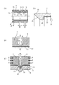
- FIG. 1 shows a state before connection of an aluminum tube according to the first embodiment of the present invention.
- FIG. 2 shows a connection completion state.
- This pipe joint structure is a pipe joint structure that includes a joint body 1 with a male thread and a cap nut 3 that is screwed onto the male thread 2 and connects an aluminum pipe 4, and is particularly suitable as a refrigerant pipe. It is a simple configuration.
- the aluminum pipe 4 and the pipe joint 6 are connected without flaring the end part 5 of the aluminum pipe 4.
- the joint body 1 and the cap nut 3 are made of brass, for example.
- a refrigerant such as an air conditioner flows through the aluminum pipe 4 and the pipe joint 6.
- FIG. 3A shows an aluminum compression deformation sleeve 7.
- the compression deformation sleeve 7 has two U-shaped concave grooves 9 on the outer peripheral surface 8. As shown in FIGS. 1 and 2, the compression deformation sleeve 7 is stored in the internal storage space 10 of the cap nut 3.
- a seal layer 12 is integrally provided in advance on the inner peripheral surface 11 of the compression deformation sleeve 7.
- the seal layer 12 is formed, for example, by painting a fluororesin such as PTFE.
- the compression deformation sleeve 7 is shown in FIG. 3C from the free state of FIG. 3B when the cap nut 3 (see FIGS. 1 and 2) and the male screw 2 of the joint body 1 are screwed together.
- the compressive force (clamping force) F in the axial direction is received from the joint body 1 and the cap nut 3, and the concave circumferential groove bottom thin wall portion 13 is plastically deformed in a U shape radially inward and inserted.
- the aluminum pipe 4 is cut out from the outer peripheral surface 14 side to prevent it from being pulled out (it has a pulling strength and prevents pulling out).
- the inner peripheral surface of the aluminum tube 4 is also plastically deformed in the radial inward direction to form the small convex portions 25.
- the width dimension W of the concave circumferential groove 9 decreases during plastic deformation. Note that the width dimension W may be zero (that is, the side surfaces 15 are in pressure contact with each other) (not shown).
- the sealing layer 12 is sealed when biting.
- the inner peripheral surface 11 of the sleeve 7 in the uncompressed state is exemplified as a smooth circumferential surface.
- an area having an axial dimension that is twice the width dimension W of the uncompressed concave circumferential groove 9 is defined as an area 45 corresponding to the concave circumferential groove bottom thin wall portion 13 and the vicinity thereof. It is sufficient that the region 45 is formed in a substantially smooth circumferential surface shape (in order to exert a pull-out resistance).
- the joint body 1 has a tapered surface 17 at the end 16 (for example, the joint body 1 has the same shape as the joint body used for the flared pipe joint of JIS B8607).
- the compression deformation sleeve 7 has a tapered surface for pressure sealing corresponding to the tapered surface 17 of the joint body 1 (with the same inclination angle ⁇ ) at the end 18. 19
- the taper surface 17 and the pressure contact seal taper surface 19 perform a sealing action by pressure contact in the same manner as a conventional flare pipe joint structure.
- 3D is an enlarged cross-sectional view of a main part showing a modification, and when the tapered surface 17 and the tapered surface 19 (as described above) are in strong pressure contact, the end 18 is excessively large (in the radially outward direction).
- the reinforcing inner collar portion 28 is projected in the radial inward direction.
- the step dimension H corresponding to the inner height of the inner flange 28 is preferably substantially the same as the thickness of the pipe (pipe) 4 (40) shown in FIGS. Furthermore, in another embodiment shown in FIG.
- the reinforcing inner collar portion 28 is also preferable to project the reinforcing inner collar portion 28 as shown by a two-dot chain line, and in another embodiment shown in FIG. 7B.
- the reinforcing inner collar portion 28 is protruded, and the step dimension H thereof is made substantially the same as the thickness dimension T 4 of the pipe (pipe) 4 (40).
- an insulating resin 21 for preventing electrolytic corrosion is applied to at least the inner surface receiving port 20 and the outer end surface 26 of the cap nut 3. Even if the cap nut is made of a metal different from aluminum such as brass, it is possible to prevent the occurrence of electrolytic corrosion between different metals.
- the resin 21 is preferably made of, for example, an epoxy resin.
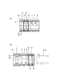
- FIG. 5 shows a state before the aluminum pipe connection according to the second embodiment of the present invention.
- FIG. 6 shows a connection completion state.
- the compression deformation sleeve 7 has two seal grooves 22 on the inner peripheral surface 11.
- a seal member 23 such as an O-ring is provided in the seal groove 22.
- the inner peripheral surface 11 of the compression deformation sleeve 7 does not have a seal layer.
- the axial length L of the compression deformation sleeve 7 is longer than that of the first embodiment.
- Other configurations are the same as those of the first embodiment. 7B corresponds to the modification of FIG. 7A, FIG. 5 and FIG.
- aluminum of the same material as the aluminum tube 4 as the sleeve 7, but if desired, on the outer surface (by plating or spraying). It can also be composed of copper coated with an aluminum layer. That is, if the electric corrosion can be prevented, the latter can be selected.
- the sleeve 7 is made of copper. .
- the other shapes and configurations of the sleeve 7 are the same as those described with reference to FIGS.
- the sleeve 7 is made of copper. To do.
- the other shapes and configurations of the sleeve 7 are the same as those described with reference to FIGS.
- FIG. 8 shows a state before the aluminum pipe connection according to the third embodiment of the present invention.
- FIG. 9 shows a connection completion state.
- a cover member 24 made of hard metal (or hard plastic) such as stainless steel is attached to the compression deformation sleeve 7 in an outer fitting shape. That is, the cover member 24 is interposed (intervened) between the inner peripheral surface 3 ⁇ / b> B of the cap nut 3 and the outer peripheral surface of the sleeve 7.
- the cover member 24 includes a cylindrical portion 42 having an axial length that is slightly shorter than the length L of the sleeve 7, and an inner collar portion 41 that is connected to the outer end of the cylindrical portion 42.
- the cover member 24 reduces frictional resistance (resistance due to pressure bonding) between the inner peripheral surface 3B of the cap nut 3 and the outer peripheral surface of the compression deformation sleeve 7 and promotes sliding (that is, for promoting relative rotational sliding). ) Cylindrical shape. 2 and 6 without the cover member 24, the sleeve 7 is compressed and deformed in the axial direction as the cap nut 3 is screwed (see arrow M in FIG. 9). The outer diameter of the sleeve 7 also increases (radially outward), strongly presses against the inner peripheral surface 3B of the cap nut 3, and the sleeve 7 rotates together with the cap nut 3. Therefore, the aluminum tube 4 (copper The tube 40) may also rotate at the same time and may be twisted.
- the cover member 24 is made of a hard material such as stainless steel and preferably made of a material having a low coefficient of friction so that the outer peripheral surface of the sleeve 7 and the inner peripheral surface of the cap nut 3 are strongly pressed (contacted).
- the above-mentioned co-rotation and twisting of the aluminum tube 4 (copper tube 40) can be prevented.
- the cap nut 3 and the compression deformation sleeve 7 may function to prevent electric corrosion.
- the inner flange portion 41 also serves to reduce the frictional resistance between the outer end surface of the sleeve 7 and the inner flange portion 3A of the cap nut 3 to make it easier to slip.
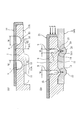
- FIGS. 11 to 14 show a fourth embodiment of the present invention.
- a claw-shaped small convex strip 50 is formed on the inner peripheral surface of the sleeve on the concave peripheral groove bottom thin wall portion 13 on the outer side of the pipe insertion side of the two concave peripheral grooves 9, 9.
- the small ridge 50 has a substantially triangular cross-sectional shape having a stepped surface 50A facing the joint body 1 at the axially central portion of the concave circumferential groove bottom thin wall portion 13, and has a resistance to retaining. It exhibits an increased pulling force resistance increasing function.
- the compressive force F when the compressive force F is received from the cap nut 3 and is compressed and deformed, it deeply bites into the outer peripheral surface of the aluminum tube 4 (or the copper tube 40) along with the U-shaped plastic deformation of the concave peripheral groove bottom thin wall portion 13.
- the pulling-out force enhancing function for further increasing the pulling-out force of the groove bottom thin wall portion 13 is exhibited.
- the groove bottom thin wall portion 13 on the left side is bent into a U shape and bites into the outer peripheral surface of the aluminum tube 4 (or copper tube 40).
- the groove wall thin wall portion 13 on the right side (outside) has a U-shaped bent portion of the base and a small convex line 50 at the top thereof, which are integrated with each other to exert a strong pull-out resistance.
- a large-diameter inner peripheral surface portion 11B having a diameter 2d larger than the inner diameter of the basic smooth inner peripheral surface portion 11A is formed, and the axial direction of the large-diameter inner peripheral surface portion 11B is formed. It is desirable to arrange (form) small ridges 50 in the middle and make the inner diameter of the small ridges 50 the same as the inner diameter of the smooth inner peripheral surface portion 11A. That is, relief of a minute dimension d (see FIG. 13) is formed on both the left and right sides (inside and outside in the axial direction) of the small ridge 50.
- the concave circumferential groove bottom thin wall portion 13 and the region 45 corresponding to the vicinity thereof are formed in the “substantially smooth” circumferential surface shape. You can say that.
- the width in the axial direction of the region 45 is defined as twice the uncompressed concave circumferential groove 9.
- the inner circumferential surface 11 is called a substantially smooth circumferential surface shape in an uncompressed state. be able to.
- reference numeral 44 denotes a cutout portion (non-existing portion) of the small protrusion 50, and the small protrusion 50 is divided into an arc shape by the plurality of cutout portions 44. Therefore, in the state in which this segmented arc-shaped small ridge 50 bites into the aluminum tube 4 (or the copper tube 40) from the outer peripheral surface 14 side, the tube rotation preventing function is exhibited. That is, in the bitten state of FIG.
- the portions where the small ridges 50 are present and the portions where the small ridges 50 are not present are alternately formed in the circumferential position, so that the tubes 4 and 40 and the sleeve 7 are relatively Therefore, the tubes 4 and 40 are reliably prevented from rotating.
- rotational torque external force
- the pipes 4 and 40 do not rotate, and thus the thin wall portion 13 that has digged in as shown in FIG. And external leakage of the fluid passing between the pipe outer peripheral surface 14 can be prevented.
- the number of the concave circumferential grooves 9 is most preferably two.
- the groove bottom thin wall portion 13 of at least one concave circumferential groove 9 is provided with a small ridge 50 that exhibits a function of enhancing the pull-out resistance.
- the above-mentioned compression deformation sleeve 7 of the present invention is characterized in that it is a “short cylindrical type”.
- the “short cylindrical type” means that an outer diameter dimension is D and a length dimension is D.
- L is defined, 0.5 ⁇ L / D ⁇ 3.0 is defined.
- one of the features of the present invention is that such a short cylindrical circular inner peripheral surface receives a compressive force F and causes plastic deformation in which the concave peripheral groove bottom thin wall portion 13 protrudes radially inward. Then, from the outer peripheral surface 14 side of the inserted aluminum tube 4 or copper tube 40, it bites into a stable U-shape and prevents it from coming off.
- the small ridge 50 has a resistance to increase the resistance against retaining.
- This is a configuration that exerts a pulling force enhancing function. Since the “short cylindrical type” sleeve 7 always maintains a stable posture from an uncompressed state to a compressed state, the local (small) concave groove bottom thin wall portion 13 is as shown in FIGS.
- FIGS. 5 to 6, or as shown in FIGS. 11 to 12, etc. as shown in FIGS. 14 (A) to 14 (B), a stable midway posture of plastic deformation is maintained. The final pipe biting plastic deformation can be performed.
- the concave circumferential groove 9 is U-shaped, in addition to the U-shaped having a large rounded shape, a square U-shape or a bulging or V-shaped groove may be used.
- the inner end surface 28a of the inner flange portion 28 corresponds to an axially orthogonal planar stepped surface having a step size H (substantially equal to the thickness of the tube 4 (40)).
- the inclined line of the tapered surface 19 with the inclination angle ⁇ forms a part of the outer end surface of the inner flange portion 28 (without a bent portion), and the inner end portion 19C of the inclined line has a shaft It connects with the center orthogonal plane part 28b (refer FIG. 13).
- the thickness of the end portion 18 of the sleeve 7 is increased.
- the reinforcing action associated with the increase in thickness prevents excessive diameter-expanding plastic deformation, and when the tapered surfaces 19 and 17 are further pressed against each other by further screwing, the axis orthogonal plane portion 28b is By abutting against the distal end surface 16A of the joint main body 1 and the stopper action, the cap nut 3 is prevented from excessively screwing, and excessively large diameter plastic deformation is reliably prevented.
- the inner flange portion 28 has an end portion 18 due to a reinforcing action accompanying an increase in the thickness (cross-sectional area) and a stopper action by the step-shaped axially orthogonal plane portion 28b contacting the tip face 16A. Can be prevented from expanding (excessive screwing of the cap nut 3).
- the number of U-shaped concave circumferential grooves 9 is most preferably two.
- U-shaped concave circumferential groove 9 is one, when the concave circumferential groove bottom thin wall portion 13 is plastically deformed, slippage easily occurs between the aluminum pipe 4 (displacement easily), and the same in the axial direction of the pipe. This is because it may be difficult to bite into the position, and in the case of three, unnecessary stress (internal stress) may remain between the U-shaped concave grooves 9.
- aluminum includes an aluminum alloy
- “copper” includes a copper-based alloy.
- the design of the present invention can be changed, and the cover member 24 can be interposed in the embodiment shown in FIGS. 5 and 6 (not shown).
- the compression deformation sleeve 7 may have one or three concave circumferential grooves 9 on the outer peripheral surface 8.
- the compression deformation sleeve 7 may have one seal groove 22 on the inner peripheral surface 11.
- the resin 21 may be coated on the entire surface of the cap nut 3.
- the present invention includes the cylindrical compression deformation sleeve 7 which is accommodated in the cap nut 3 and has the concave circumferential groove 9 on the outer peripheral surface 8, and the compression deformation sleeve 7 has a concave circumference.
- a concave groove bottom thin wall portion 13 is formed in the inner part of the groove 9, receives the compressive force F in the axial direction by the screw nut 3 being screwed, and decreases the width W of the concave groove 9 while reducing the width dimension W of the concave circumferential groove 9.
- the bottom thin wall portion 13 is plastically deformed so as to protrude radially inward, and is configured to bite in from the outer peripheral surface 14 side of the inserted aluminum tube 4 to prevent the aluminum tube 4 from being removed.
- connection (pipe) work can be performed. Furthermore, it is not necessary to perform a flaring process on the end of the aluminum tube 4 which is difficult to be plastically processed, and the working efficiency is good. Further, the number of parts is small, the part shape is simple, and it can be easily assembled.
- a cylindrical compression deformation sleeve 7 having a concave groove 9 on the outer peripheral surface 8 is housed inside the cap nut 3, and the compression deformation sleeve 7 is provided at the back of the concave peripheral groove 9.
- the concave circumferential groove bottom thin wall portion 13 is formed, receives the compressive force F in the axial direction as the cap nut 3 is screwed, and the concave circumferential groove bottom thin wall portion 13 decreases while the width dimension W of the concave circumferential groove 9 decreases. Is deformed so as to protrude radially inward, and is inserted from the outer peripheral surface 14 side of the inserted copper pipe 40 to prevent the copper pipe 40 from being removed. ) Work can be done.
- the tube 4 Stable plastic deformation can be performed on the outer peripheral surface of (40).
- a pipe joint structure for a refrigerant or the like that includes a joint body 1 with a male thread and a cap nut 3 that is screwed onto a male thread 2 of the joint body 1 and that connects an aluminum pipe 4 (for a refrigerant or the like).
- the nut 3 is housed in the internal storage space 10 and has a concave circumferential groove 9 on the outer peripheral surface 8.
- the sleeve for compression deformation that receives the compressive force F in the axial direction and plastically deforms the concave circumferential groove bottom thin wall portion 13 radially inward, and bites in from the outer peripheral surface 14 side of the inserted aluminum tube 4 to prevent it from being removed. 7, it is possible to quickly perform a strong connection (pipe) operation. Furthermore, there is no need to flare the aluminum tube 4, and the working efficiency is good. Further, the number of parts is small, the part shape is simple, and it can be easily assembled.
- the compression deformation sleeve 7 is preferably made of aluminum or copper coated with an aluminum layer, so that there is no fear of electric corrosion on the aluminum tube 4.
- a pipe joint structure for a refrigerant or the like that includes a joint body 1 with a male thread and a cap nut 3 that is screwed onto the male thread 2 of the joint body 1 and connects a copper pipe 40 (for a refrigerant or the like).
- the nut 3 is housed in the internal housing space 10 and has a concave circumferential groove 9 on the outer peripheral surface 8.
- the joint body 1 and the cap nut 3 In response to the compressive force F in the axial direction, the concave circumferential groove bottom thin wall portion 13 is plastically deformed radially inward and bites in from the outer peripheral surface 14 side of the inserted copper tube 40 to prevent it from being removed. Therefore, the conventional flare processing to the end of the copper pipe is completely unnecessary, a quick piping work can be performed, the work efficiency can be improved, and a powerful connection complete structure is obtained. Furthermore, the number of parts is small and the part shape is simple.
- the compression deformation sleeve 7 is made of copper, there is no fear of electric corrosion with respect to the copper tube 40. Further, since the seal layer 12 is integrally provided in advance on the inner peripheral surface 11 of the compression deformation sleeve 7 so as to be in a sealed state when biting in, the sealing performance is good. Further, since the compression deformation sleeve 7 has the seal groove 22 on the inner peripheral surface 11 and the seal member 23 is housed in the seal groove 22, the sealing performance can be further improved and stabilized. In addition, although rainwater etc.
- the pipe is made of aluminum, and the joint body 1 and the cap nut Even if 3 is made of a metal different from aluminum such as brass, it is possible to prevent the occurrence of electrolytic corrosion between different metals.
- the inner peripheral surface 3B of the cap nut 3 is configured by interposing a cylindrical cover member for assisting relative rotational slippage between the inner peripheral surface of the cap nut and the outer peripheral surface of the compression deformation sleeve. Then, the problem that the aluminum tube 4 or the copper tube 40 is finally twisted by rotating lightly between the sleeve 7 and the outer peripheral surface of the sleeve 7 is surely facilitated, and the pipe connection work is surely facilitated.
- the present invention includes a cylindrical compression deformation sleeve 7 which is housed inside the cap nut 3 and has a concave circumferential groove 9 on the outer peripheral surface 8.
- a concave groove bottom thin wall portion 13 is formed at the back of the concave groove 9, and the concave groove bottom thin wall portion 13 is formed with a small protrusion 50 on the sleeve inner peripheral surface side.
- the aluminum tube 4 is inserted into the outer peripheral surface 14 side so as to prevent the aluminum tube 4 from being pulled out, and the small protrusion 50 has a resistance to pulling that increases resistance to the retaining. Since it is configured to demonstrate the power enhancement function, it can quickly and strongly connect ( Tube) capable of performing the work. Furthermore, there is no need to flare the aluminum tube 4, and the working efficiency is good. Further, the number of parts is small, the part shape is simple, and it can be easily assembled. In particular, the pull-out resistance is remarkably strong by the cooperation of the concave circumferential groove bottom wall 13 and the small ridges 50.
- a cylindrical compression deformation sleeve 7 which is housed inside the cap nut 3 and has a concave groove 9 on the outer peripheral surface 8 is provided.
- a concave circumferential groove bottom thin wall portion 13 is formed in the inner portion of the groove 9, and the concave circumferential groove bottom thin wall portion 13 is formed with a small protrusion 50 on the sleeve inner circumferential surface side.
- Axial compression force F is received by the screwing, and the concave groove bottom thin wall portion 13 is plastically deformed so as to protrude radially inward while the width dimension W of the concave groove 9 is reduced.
- the structure is such that the inserted copper tube 40 bites in from the outer peripheral surface 14 side to prevent the copper tube 40 from being pulled out, and the small protrusion 50 has an increased resistance to pulling that increases the resistance to the retaining. Since it is configured to demonstrate its functions, conventional flare processing to the end of the copper tube is completely unnecessary It becomes to obtain perform quick plumbing to give work to improve work efficiency, and a structure of a strong connection completion. Furthermore, the number of parts is small and the part shape is simple. In particular, the pull-out resistance is remarkably strong by the cooperation of the concave circumferential groove bottom wall 13 and the small ridges 50.
- the small ridges 50 are formed in a circular arc shape by a plurality of notches 44, and the small ridges 50 are configured to exert a tube rotation preventing function while being bitten from the outer peripheral surface 14 side.
- the sleeve 7 is plastically deformed by receiving the compressive force F in the axial direction, and at the same time the rotation of the tubes 4 and 40 can be prevented and the sealing performance can be prevented from being lowered, and excellent sealing performance is exhibited over a long period of time. To do.
Abstract
Provided is a pipe joint structure which is configured so that, when a pipe consists of aluminum, the pipe joint structure enables quick and firm connection of the pipe without providing a flare to an end of the pipe. A pipe joint structure comprises a joint body (1) equipped with a male thread and also comprises a cap nut (3) which is engaged with the male thread (2) of the joint body (1), and the pipe joint structure is used for the connection of an aluminum pipe (4). The pipe joint structure has a sleeve (7) for compression and deformation. The sleeve (7) is received in the inner receiving space (10) of the cap nut (3) and has a peripheral groove (9) in the outer peripheral surface (8) thereof. The sleeve (7) receives axial compression force from both the joint body (1) and the cap nut (3) when connecting the cap nut (3) and the male thread (2) of the joint body (1) by threads. As a result, a thin-walled section (13) at the bottom of the peripheral groove is plastically deformed radially inward, bites into the inserted aluminum pipe (4) from the outer peripheral surface (14) side thereof, and retains the aluminum pipe (4).
Description
本発明は、管継手構造に関する。
The present invention relates to a pipe joint structure.
管継手の一種として、フレア継手が広く用いられている(例えば、特許文献1参照)。
一般に、図11に示すように、雄ネジ付き継手本体30のテーパ面31と、継手本体30の雄ネジ32に螺着される袋ナット33のテーパ面34の間に、銅製パイプ35の端部を拡径テーパ状に塑性加工して成るフレア端部37を、挟持させて圧接力により密封する構造である。 A flare joint is widely used as a kind of pipe joint (see, for example, Patent Document 1).
In general, as shown in FIG. 11, the end portion of thecopper pipe 35 is between the tapered surface 31 of the male threaded joint body 30 and the tapered surface 34 of the cap nut 33 that is screwed onto the male thread 32 of the joint body 30. This is a structure in which a flare end portion 37 formed by plastic working is expanded and tapered so as to be sandwiched and sealed by a pressing force.
一般に、図11に示すように、雄ネジ付き継手本体30のテーパ面31と、継手本体30の雄ネジ32に螺着される袋ナット33のテーパ面34の間に、銅製パイプ35の端部を拡径テーパ状に塑性加工して成るフレア端部37を、挟持させて圧接力により密封する構造である。 A flare joint is widely used as a kind of pipe joint (see, for example, Patent Document 1).
In general, as shown in FIG. 11, the end portion of the
しかし、近年、パイプ35の材質として、高価で重い銅より、安価で軽いアルミニウムを用いたいという要望が強い。パイプ35がアルミニウムから成る場合、フレア加工を施すのが困難であるという欠点があった。勿論、銅管についても、上記フレア加工を現場で行う必要があるため、配管作業能率アップを阻害しているという欠点があった。また、それらの問題を回避するために種々の管継手構造が提案されているが、部品点数が多く、複雑な形状の部品を必要とし、組立時に手間がかかるという欠点があった。
However, in recent years, there is a strong demand to use cheap and light aluminum as the material of the pipe 35 rather than expensive and heavy copper. When the pipe 35 is made of aluminum, there is a drawback that it is difficult to perform flare processing. Of course, the copper pipe also has the disadvantage of hindering the efficiency of piping work because the flare processing needs to be performed on site. In order to avoid these problems, various pipe joint structures have been proposed. However, there are disadvantages in that the number of parts is large, complicated shaped parts are required, and labor is required during assembly.
解決しようとする課題は、アルミニウム管にフレア加工を施すのが困難だという点である。あるいは、銅管にあっても、フレア加工が配管作業現場の作業能率アップを阻害していた点である。また、それらの問題を回避するための種々の管継手構造では、部品点数が多く、複雑な形状の部品を必要とし、組立時に手間がかかる点である。
The problem to be solved is that it is difficult to flare the aluminum tube. Or even if it exists in a copper pipe, it is the point to which the flare process had inhibited the work efficiency improvement of the piping work site. Moreover, in various pipe joint structures for avoiding these problems, the number of parts is large and parts having complicated shapes are required, which takes time during assembly.
本発明に係る管継手構造は、袋ナットの内部に収納されると共に、外周面に凹周溝を有する円筒形状の圧縮変形用スリーブを具備し、該圧縮変形スリーブは、上記凹周溝の奥部に凹周溝底薄壁部が形成され、上記袋ナットの螺進によってアキシャル方向の圧縮力を受けて、上記凹周溝の幅寸法が減少しつつ上記凹周溝底薄壁部がラジアル内方向へ突出するように塑性変形して、挿入されているアルミニウム管の外周面側から食い込んで該アルミニウム管の抜止めをするように構成したものである。
The pipe joint structure according to the present invention includes a cylindrical compression deformation sleeve that is housed in a cap nut and has a concave circumferential groove on an outer peripheral surface, and the compression deformation sleeve is located at the back of the concave circumferential groove. A concave groove bottom thin wall portion is formed in the portion, and receives the compressive force in the axial direction by the screw nut being screwed, and the concave groove bottom thin wall portion is radial while the width dimension of the concave groove decreases. It is configured to be plastically deformed so as to protrude inward and to bite in from the outer peripheral surface side of the inserted aluminum tube to prevent the aluminum tube from being removed.
また、本発明に係る管継手構造は、袋ナットの内部に収納されると共に、外周面に凹周溝を有する円筒形状の圧縮変形用スリーブを具備し、該圧縮変形スリーブは、上記凹周溝の奥部には、凹周溝底薄壁部が形成され、上記袋ナットの螺進によってアキシャル方向の圧縮力を受けて、上記凹周溝の幅寸法が減少しつつ上記凹周溝底薄壁部がラジアル内方向へ突出するように塑性変形して、挿入されている銅管の外周面側から食い込んで該銅管の抜止めをするように構成したものである。
また、上記圧縮変形スリーブの内周面は、上記凹周溝底薄壁部及びその近傍に対応した領域に於て、略平滑状の円周面形状に形成されている。 The pipe joint structure according to the present invention includes a cylindrical compression deformation sleeve that is housed in a cap nut and has a concave circumferential groove on an outer peripheral surface, and the compression deformation sleeve includes the concave circumferential groove. A recessed groove bottom thin wall portion is formed at the back of the groove, and receives the compressive force in the axial direction due to the screw nut being screwed, so that the width of the groove is reduced and the groove groove thinness is reduced. The wall portion is plastically deformed so as to protrude radially inward, and is configured to bite in from the outer peripheral surface side of the inserted copper tube to prevent the copper tube from being removed.
Further, the inner peripheral surface of the compression deformation sleeve is formed in a substantially smooth circumferential surface shape in a region corresponding to the concave peripheral groove bottom thin wall portion and its vicinity.
また、雄ネジ付き継手本体と、該継手本体の雄ネジに螺着される袋ナットと、を備え、アルミニウム管を接続する管継手構造に於て、上記袋ナットの内部収納空間に収納されると共に、外周面に凹周溝を有し、上記袋ナットと上記継手本体の雄ネジを螺着させる際に上記継手本体と上記袋ナットからアキシャル方向の圧縮力を受けて、凹周溝底薄壁部がラジアル内方向へ塑性変形して、挿入されている上記アルミニウム管の外周面側から食い込んで抜止めする圧縮変形用スリーブを有するものである。
また、上記圧縮変形用スリーブは、アルミニウム又はアルミニウム層を被覆した銅から成るものである。 In addition, in a pipe joint structure that includes a joint body with a male thread and a cap nut that is screwed onto the male thread of the joint main body, and is connected to the aluminum pipe, the joint body is stored in the internal storage space of the cap nut. In addition, the outer peripheral surface has a concave groove, and when the cap nut and the male screw of the joint main body are screwed together, the concave peripheral groove bottom is thinned by receiving a compressive force in the axial direction from the joint main body and the cap nut. The wall portion is plastically deformed radially inward, and has a compression deformation sleeve that bites in from the outer peripheral surface side of the inserted aluminum tube and prevents it from being pulled out.
The compression deformation sleeve is made of aluminum or copper coated with an aluminum layer.
また、雄ネジ付き継手本体と、該継手本体の雄ネジに螺着される袋ナットと、を備え、銅管を接続する管継手構造に於て、上記袋ナットの内部収納空間に収納されると共に、外周面に凹周溝を有し、上記袋ナットと上記継手本体の雄ネジを螺着させる際に上記継手本体と上記袋ナットからアキシャル方向の圧縮力を受けて、凹周溝底薄壁部がラジアル内方向へ塑性変形して、挿入されている上記銅管の外周面側から食い込んで抜止めする圧縮変形用スリーブを有するものである。
In addition, in a pipe joint structure that includes a joint body with a male thread and a cap nut that is screwed onto the male thread of the joint body, the pipe nut is stored in the internal storage space of the cap nut. In addition, the outer peripheral surface has a concave groove, and when the cap nut and the male screw of the joint main body are screwed together, the concave peripheral groove bottom is thinned by receiving a compressive force in the axial direction from the joint main body and the cap nut. The wall portion is plastically deformed radially inward, and has a compression deformation sleeve that bites in from the outer peripheral surface side of the inserted copper tube and prevents it from being pulled out.
また、上記圧縮変形用スリーブは、銅から成るものである。そして、(好ましくは)上記凹周溝がU字状である。
また、上記圧縮変形用スリーブの内周面に予め一体にシール層を有して、上記食い込みの際に密封状態となるように構成したものである。
また、上記圧縮変形用スリーブが内周面にシール溝を有し、該シール溝内にシール材を内装したものである。
また、上記袋ナットの内周面と、上記圧縮変形用スリーブの外周面との間に、相対的回転滑り助長用円筒状カバー部材を介在させた構成とするも好ましい。 The compression deformation sleeve is made of copper. And (preferably) the concave circumferential groove is U-shaped.
In addition, a seal layer is integrally provided in advance on the inner peripheral surface of the compression deformation sleeve, and is configured to be in a sealed state upon the bite.
The compression deformation sleeve has a seal groove on the inner peripheral surface, and a seal material is internally provided in the seal groove.
Moreover, it is also preferable that a cylindrical cover member for assisting relative rotational slippage is interposed between the inner peripheral surface of the cap nut and the outer peripheral surface of the compression deformation sleeve.
また、本発明は、袋ナットの内部に収納されると共に、外周面に凹周溝を有する円筒形状の圧縮変形用スリーブを具備し、該圧縮変形スリーブは、未圧縮状態では、上記凹周溝の奥部には、凹周溝底薄壁部が形成され、かつ、上記凹周溝底薄壁部はスリーブ内周面側に小凸条が形成され、上記袋ナットの螺進によってアキシャル方向の圧縮力を受けて、上記凹周溝の幅寸法が減少しつつ上記凹周溝底薄壁部がラジアル内方向へ突出するように塑性変形して、挿入されているアルミニウム管の外周面側から食い込んで該アルミニウム管の抜止めをするように構成し、かつ、上記小凸条は、抜止めに対する抵抗力を増大させる耐引抜力増強機能を発揮するように構成したものである。
The present invention also includes a cylindrical compression deformation sleeve that is housed inside a cap nut and has a concave circumferential groove on the outer peripheral surface, and the compression deformation sleeve is configured to form the concave circumferential groove in an uncompressed state. A concave groove bottom thin wall portion is formed at the back of the groove, and the concave groove bottom thin wall portion is formed with a small protrusion on the inner peripheral surface side of the sleeve. The outer circumferential surface side of the inserted aluminum tube is deformed plastically so that the thin wall portion of the concave groove protrudes radially inward while the width dimension of the concave groove is reduced. The small ridges are configured so as to exert a pulling-out force enhancing function for increasing the resistance to the retaining.
また、本発明は、袋ナットの内部に収納されると共に、外周面に凹周溝を有する円筒形状の圧縮変形用スリーブを具備し、該圧縮変形スリーブは、未圧縮状態では、上記凹周溝の奥部には、凹周溝底薄壁部が形成され、かつ、上記凹周溝底薄壁部はスリーブ内周面側に小凸条が形成され、上記袋ナットの螺進によってアキシャル方向の圧縮力を受けて、上記凹周溝の幅寸法が減少しつつ上記凹周溝底薄壁部がラジアル内方向へ突出するように塑性変形して、挿入されている銅管の外周面側から食い込んで該銅管の抜止めをするように構成し、かつ、上記小凸条は、抜止めに対する抵抗力を増大させる耐引抜力増強機能を発揮するように構成したものである。
The present invention also includes a cylindrical compression deformation sleeve that is housed inside a cap nut and has a concave circumferential groove on the outer peripheral surface, and the compression deformation sleeve is configured to form the concave circumferential groove in an uncompressed state. A concave groove bottom thin wall portion is formed at the back of the groove, and the concave groove bottom thin wall portion is formed with a small protrusion on the inner peripheral surface side of the sleeve. The outer circumferential surface side of the inserted copper tube is deformed plastically so that the thin wall portion of the concave circumferential groove protrudes radially inward while the width dimension of the concave circumferential groove is reduced. The small ridges are configured to exhibit a pull-out force enhancing function for increasing the resistance against the pull-out.
また、上記小凸条は複数の切欠部によって、円弧状に分断形成され、該小凸条は上記外周面側から食い込んだ状態で、管回転防止機能を発揮するよう構成するも、場合によっては望ましい。
Further, the small ridges are formed in a circular arc shape by a plurality of notches, and the small ridges are configured to exert a tube rotation preventing function in a state of being bitten from the outer peripheral surface side. desirable.
本発明の管継手構造によれば、塑性加工が難しいアルミニウムパイプの場合、又は、従来のフレア加工を必要としていた銅製パイプの場合、いすれも、端部にフレア加工を施す必要がなく、作業効率が良い。しかも、袋ナットを螺進するだけで、強力な引抜力を発揮し、かつ、密封性も発揮する接続(配管)を迅速・容易に行い得る。また、部品点数が少なく、部品形状がシンプルであって、容易に組立てることができる。特に、冷媒用配管に好適である。
According to the pipe joint structure of the present invention, in the case of an aluminum pipe that is difficult to be plastically processed, or in the case of a copper pipe that conventionally requires flaring, it is not necessary to perform flaring on the end portion. Efficiency is good. Moreover, by simply screwing the cap nut, a connection (pipe) that exhibits a strong pulling force and also exhibits a sealing property can be quickly and easily performed. Further, the number of parts is small, the part shape is simple, and it can be easily assembled. In particular, it is suitable for refrigerant piping.
図1は、本発明の第1の実施の形態のアルミニウム管接続前の状態を示す。図2は、接続完了状態を示す。この管継手構造は、雄ネジ付き継手本体1と、雄ネジ2に螺着される袋ナット3と、を備え、アルミニウム管4を接続する管継手構造であって、特に、冷媒用配管として好適な構成である。アルミニウム管4の端部5にフレア加工を施すことなく、アルミニウム管4と管継手6が接続される。継手本体1及び袋ナット3は、例えば真鍮から成る。アルミニウム管4及び管継手6の内部をエアコン等の冷媒が流れる。
FIG. 1 shows a state before connection of an aluminum tube according to the first embodiment of the present invention. FIG. 2 shows a connection completion state. This pipe joint structure is a pipe joint structure that includes a joint body 1 with a male thread and a cap nut 3 that is screwed onto the male thread 2 and connects an aluminum pipe 4, and is particularly suitable as a refrigerant pipe. It is a simple configuration. The aluminum pipe 4 and the pipe joint 6 are connected without flaring the end part 5 of the aluminum pipe 4. The joint body 1 and the cap nut 3 are made of brass, for example. A refrigerant such as an air conditioner flows through the aluminum pipe 4 and the pipe joint 6.
図3(A)にアルミニウム製圧縮変形用スリーブ7を示す。圧縮変形用スリーブ7は、外周面8に2本のU字状凹周溝9を有する。図1・図2に示すように、圧縮変形用スリーブ7が袋ナット3の内部収納空間10に収納される。
FIG. 3A shows an aluminum compression deformation sleeve 7. The compression deformation sleeve 7 has two U-shaped concave grooves 9 on the outer peripheral surface 8. As shown in FIGS. 1 and 2, the compression deformation sleeve 7 is stored in the internal storage space 10 of the cap nut 3.
図3(A)(B)に示すように、圧縮変形用スリーブ7の内周面11に予め一体にシール層12を有する。シール層12は、例えば、PTFE等のフッ素樹脂を塗装することにより形成する。圧縮変形用スリーブ7は、袋ナット3(図1・図2参照)と継手本体1の雄ネジ2を螺着させる際に、図3(B)の自由状態から、図3(C)に示すように、継手本体1と袋ナット3からアキシャル方向の圧縮力(締付力)Fを受けて、凹周溝底薄壁部13がラジアル内方向へU字状に塑性変形して、挿入されているアルミニウム管4の外周面14側から食い込んで抜止めする(引抜耐力を有し、引抜けを防止する)。このとき、図2と図3(C)に示すように、アルミニウム管4の内周面もラジアル内方向に塑性変形して小凸条部25を形成する。凹周溝9の幅寸法Wは、塑性変形の際、減少する。なお、幅寸法Wがゼロとなる(すなわち側面15どうしが圧接する)も良い(図示省略)。また、図3(C)のように、食い込みの際にシール層12によって密封状態となる。
3A and 3B, a seal layer 12 is integrally provided in advance on the inner peripheral surface 11 of the compression deformation sleeve 7. The seal layer 12 is formed, for example, by painting a fluororesin such as PTFE. The compression deformation sleeve 7 is shown in FIG. 3C from the free state of FIG. 3B when the cap nut 3 (see FIGS. 1 and 2) and the male screw 2 of the joint body 1 are screwed together. As described above, the compressive force (clamping force) F in the axial direction is received from the joint body 1 and the cap nut 3, and the concave circumferential groove bottom thin wall portion 13 is plastically deformed in a U shape radially inward and inserted. The aluminum pipe 4 is cut out from the outer peripheral surface 14 side to prevent it from being pulled out (it has a pulling strength and prevents pulling out). At this time, as shown in FIGS. 2 and 3C, the inner peripheral surface of the aluminum tube 4 is also plastically deformed in the radial inward direction to form the small convex portions 25. The width dimension W of the concave circumferential groove 9 decreases during plastic deformation. Note that the width dimension W may be zero (that is, the side surfaces 15 are in pressure contact with each other) (not shown). In addition, as shown in FIG. 3C, the sealing layer 12 is sealed when biting.
ところで、図1,図2,図3(A)に示した実施の形態では、未圧縮状態のスリーブ7の内周面11は平滑円周面状の場合を例示している。しかしながら、本発明では、未圧縮状態の凹周溝9の幅寸法Wの2倍のアキシャル方向寸法の領域を、凹周溝底薄壁部13及びその近傍に対応した領域45と定義して、その領域45が略平滑状の円周面形状に形成されれば(耐引抜力を発揮するうえで)十分である。
By the way, in the embodiment shown in FIG. 1, FIG. 2, FIG. 3A, the inner peripheral surface 11 of the sleeve 7 in the uncompressed state is exemplified as a smooth circumferential surface. However, in the present invention, an area having an axial dimension that is twice the width dimension W of the uncompressed concave circumferential groove 9 is defined as an area 45 corresponding to the concave circumferential groove bottom thin wall portion 13 and the vicinity thereof. It is sufficient that the region 45 is formed in a substantially smooth circumferential surface shape (in order to exert a pull-out resistance).
図1と図2に示すように、継手本体1は、端部16にテーパ面17を有する(例えばJIS B8607のフレア管継手に用いられる継手本体と同一形状とする)。図3(A)及び図1・図2に示すように、圧縮変形用スリーブ7は、端部18に、継手本体1のテーパ面17に対応した(同一傾斜角度θの)圧接シール用テーパ面19を有する。テーパ面17と圧接シール用テーパ面19は、従来のフレア管継手の管継手構造と同様に圧接により密封作用をなす。
図3(D)は、変形例を示す要部拡大断面図であって、(上述した)テーパ面17とテーパ面19とが強く圧接した際に、端部18が(ラジアル外方向に)過大な拡径塑性変形を発生することを防止するため、補強用内鍔部28をラジアル内方向に突設させている。なお、この内鍔部28の内方高さに相当する段差寸法Hは、図1,図2の管(パイプ)4(40)の肉厚寸法と略同一とするのが望ましい。
さらに、後述する図10に示した別の実施の形態に於て、補強用内鍔部28を2点鎖線のように突設するも好ましく、また、図7(B)に示した他の実施形態のように、補強用内鍔部28を突設して、その段差寸法Hを、管(パイプ)4(40)の肉厚寸法T4と略同一とする。 As shown in FIGS. 1 and 2, thejoint body 1 has a tapered surface 17 at the end 16 (for example, the joint body 1 has the same shape as the joint body used for the flared pipe joint of JIS B8607). As shown in FIG. 3A and FIGS. 1 and 2, the compression deformation sleeve 7 has a tapered surface for pressure sealing corresponding to the tapered surface 17 of the joint body 1 (with the same inclination angle θ) at the end 18. 19 The taper surface 17 and the pressure contact seal taper surface 19 perform a sealing action by pressure contact in the same manner as a conventional flare pipe joint structure.
FIG. 3D is an enlarged cross-sectional view of a main part showing a modification, and when the taperedsurface 17 and the tapered surface 19 (as described above) are in strong pressure contact, the end 18 is excessively large (in the radially outward direction). In order to prevent the occurrence of large-diameter plastic deformation, the reinforcing inner collar portion 28 is projected in the radial inward direction. The step dimension H corresponding to the inner height of the inner flange 28 is preferably substantially the same as the thickness of the pipe (pipe) 4 (40) shown in FIGS.
Furthermore, in another embodiment shown in FIG. 10 to be described later, it is also preferable to project the reinforcinginner collar portion 28 as shown by a two-dot chain line, and in another embodiment shown in FIG. 7B. As in the embodiment, the reinforcing inner collar portion 28 is protruded, and the step dimension H thereof is made substantially the same as the thickness dimension T 4 of the pipe (pipe) 4 (40).
図3(D)は、変形例を示す要部拡大断面図であって、(上述した)テーパ面17とテーパ面19とが強く圧接した際に、端部18が(ラジアル外方向に)過大な拡径塑性変形を発生することを防止するため、補強用内鍔部28をラジアル内方向に突設させている。なお、この内鍔部28の内方高さに相当する段差寸法Hは、図1,図2の管(パイプ)4(40)の肉厚寸法と略同一とするのが望ましい。
さらに、後述する図10に示した別の実施の形態に於て、補強用内鍔部28を2点鎖線のように突設するも好ましく、また、図7(B)に示した他の実施形態のように、補強用内鍔部28を突設して、その段差寸法Hを、管(パイプ)4(40)の肉厚寸法T4と略同一とする。 As shown in FIGS. 1 and 2, the
FIG. 3D is an enlarged cross-sectional view of a main part showing a modification, and when the tapered
Furthermore, in another embodiment shown in FIG. 10 to be described later, it is also preferable to project the reinforcing
図4に示すように、袋ナット3の少なくとも内面受口20及び外端面26に、電蝕防止のための絶縁性樹脂21を塗装する。袋ナットが真鍮等のアルミニウムとは異なる金属から成っても、異種金属の間での電蝕の発生を防止することができる。樹脂21は、例えば、エポキシ樹脂から成るのが好ましい。
As shown in FIG. 4, an insulating resin 21 for preventing electrolytic corrosion is applied to at least the inner surface receiving port 20 and the outer end surface 26 of the cap nut 3. Even if the cap nut is made of a metal different from aluminum such as brass, it is possible to prevent the occurrence of electrolytic corrosion between different metals. The resin 21 is preferably made of, for example, an epoxy resin.
図5は、本発明の第2の実施の形態のアルミニウム管接続前の状態を示す。図6は、接続完了状態を示す。図5~図7に示すように、圧縮変形用スリーブ7が内周面11に2本のシール溝22を有する。シール溝22内にOリング等のシール材23が内装される。圧縮変形用スリーブ7の内周面11はシール層を有していない。(圧縮変形用スリーブ7のアキシャル方向長さ寸法Lは、第1の実施の形態より長くなる。)その他の構成は、第1の実施の形態と同様である。
ところで、図7(B)は、図7(A),図5,図6の変形例に相当するものであって、シール材23(シール溝22)の位置と、凹周溝9の位置とを、アキシャル方向に入れ替えた構成である。この図7(B)のように構成すれば、配管接続完了状態下(図6参照)で、凹周溝底薄壁部13が管4(40)の外周面14への圧着による密封作用が第1段階で働き、仮にこの密封作用が不十分な場合に、(ラジアル外方側の)シール材23によって、確実な密封作用をなすことができる。 FIG. 5 shows a state before the aluminum pipe connection according to the second embodiment of the present invention. FIG. 6 shows a connection completion state. As shown in FIGS. 5 to 7, thecompression deformation sleeve 7 has two seal grooves 22 on the inner peripheral surface 11. A seal member 23 such as an O-ring is provided in the seal groove 22. The inner peripheral surface 11 of the compression deformation sleeve 7 does not have a seal layer. (The axial length L of the compression deformation sleeve 7 is longer than that of the first embodiment.) Other configurations are the same as those of the first embodiment.
7B corresponds to the modification of FIG. 7A, FIG. 5 and FIG. 6, and the position of the sealing material 23 (seal groove 22) and the position of the concavecircumferential groove 9 are as follows. In the axial direction. 7B, when the pipe connection is completed (refer to FIG. 6), the concave circumferential groove bottom thin wall portion 13 is sealed by the pressure bonding to the outer peripheral surface 14 of the tube 4 (40). If the sealing action is insufficient when the first stage works and the sealing action is insufficient, a reliable sealing action can be achieved by the sealing material 23 (on the radial outer side).
ところで、図7(B)は、図7(A),図5,図6の変形例に相当するものであって、シール材23(シール溝22)の位置と、凹周溝9の位置とを、アキシャル方向に入れ替えた構成である。この図7(B)のように構成すれば、配管接続完了状態下(図6参照)で、凹周溝底薄壁部13が管4(40)の外周面14への圧着による密封作用が第1段階で働き、仮にこの密封作用が不十分な場合に、(ラジアル外方側の)シール材23によって、確実な密封作用をなすことができる。 FIG. 5 shows a state before the aluminum pipe connection according to the second embodiment of the present invention. FIG. 6 shows a connection completion state. As shown in FIGS. 5 to 7, the
7B corresponds to the modification of FIG. 7A, FIG. 5 and FIG. 6, and the position of the sealing material 23 (seal groove 22) and the position of the concave
既述の第1・第2の実施の形態に於て、スリーブ7としては、アルミニウム管4と同一材質のアルミニウムを用いることが好ましいが、所望により、外表面に(メッキ加工や溶射等によって)アルミニウム層が被覆された銅をもって構成することもできる。つまり、電蝕を防止することができれば、後者を選択可能である。
In the first and second embodiments already described, it is preferable to use aluminum of the same material as the aluminum tube 4 as the sleeve 7, but if desired, on the outer surface (by plating or spraying). It can also be composed of copper coated with an aluminum layer. That is, if the electric corrosion can be prevented, the latter can be selected.
次に、他の実施の形態について説明すると、図1~図3に示した第1の実施の形態に於て、パイプとして銅管40を使用する場合には、スリーブ7の材質を銅とする。スリーブ7の他の形状や構成は、図1~図3で述べた場合と同様であるので詳細を省略する。
次に、さらに別の実施の形態について説明すると、図5と図6に示した第2の実施の形態に於て、パイプとして銅管40を使用する場合には、スリーブ7の材質を銅とする。スリーブ7の他の形状や構成は、図5と図6で述べた場合と同様であるので詳細を省略する。
なお、いずれの実施の形態の場合も、パイプが銅管40の場合には、図4に示した袋ナット3を銅として、樹脂21の被膜を省略可能な場合がある。 Next, another embodiment will be described. In the first embodiment shown in FIGS. 1 to 3, when thecopper tube 40 is used as the pipe, the sleeve 7 is made of copper. . The other shapes and configurations of the sleeve 7 are the same as those described with reference to FIGS.
Next, another embodiment will be described. In the second embodiment shown in FIGS. 5 and 6, when thecopper tube 40 is used as a pipe, the sleeve 7 is made of copper. To do. The other shapes and configurations of the sleeve 7 are the same as those described with reference to FIGS.
In any of the embodiments, when the pipe is thecopper tube 40, the cap nut 3 shown in FIG.
次に、さらに別の実施の形態について説明すると、図5と図6に示した第2の実施の形態に於て、パイプとして銅管40を使用する場合には、スリーブ7の材質を銅とする。スリーブ7の他の形状や構成は、図5と図6で述べた場合と同様であるので詳細を省略する。
なお、いずれの実施の形態の場合も、パイプが銅管40の場合には、図4に示した袋ナット3を銅として、樹脂21の被膜を省略可能な場合がある。 Next, another embodiment will be described. In the first embodiment shown in FIGS. 1 to 3, when the
Next, another embodiment will be described. In the second embodiment shown in FIGS. 5 and 6, when the
In any of the embodiments, when the pipe is the
図8は、本発明の第3の実施の形態のアルミニウム管接続前の状態を示す。図9は、接続完了状態を示す。図8~図10では、圧縮変形用スリーブ7に、ステンレス鋼等の硬質金属(又は硬質プラスチック)製のカバー部材24が外嵌状に取り付けられている。つまり、袋ナット3の内周面3Bと、スリーブ7の外周面との間に、カバー部材24が介在(介装)している。このカバー部材24は、スリーブ7の長さ寸法Lよりも僅かに短いアキシャル方向長さ寸法の円筒部42と、その外端に連設された内鍔部41とから成る。
カバー部材24は、袋ナット3の内周面3Bと、圧縮変形用スリーブ7の外周面との摩擦抵抗(圧着による抵抗)を低減し、滑りを助長するため(即ち、相対的回転滑り助長用)の円筒状のものである。このカバー部材24が無い図2、図6に示した状態下で、スリーブ7が、袋ナット3の螺進(図9矢印M参照)に伴って、アキシャル方向に圧縮変形するときに、スリーブ7の外径寸法も増加する(ラジアル外方への)変形を生じ、袋ナット3の内周面3Bに強く圧着して、スリーブ7が袋ナット3と共廻りし、故に、アルミニウム管4(銅管40)も同時に共廻りして、捩れを発生する虞れがあった。 FIG. 8 shows a state before the aluminum pipe connection according to the third embodiment of the present invention. FIG. 9 shows a connection completion state. 8 to 10, acover member 24 made of hard metal (or hard plastic) such as stainless steel is attached to the compression deformation sleeve 7 in an outer fitting shape. That is, the cover member 24 is interposed (intervened) between the inner peripheral surface 3 </ b> B of the cap nut 3 and the outer peripheral surface of the sleeve 7. The cover member 24 includes a cylindrical portion 42 having an axial length that is slightly shorter than the length L of the sleeve 7, and an inner collar portion 41 that is connected to the outer end of the cylindrical portion 42.
Thecover member 24 reduces frictional resistance (resistance due to pressure bonding) between the inner peripheral surface 3B of the cap nut 3 and the outer peripheral surface of the compression deformation sleeve 7 and promotes sliding (that is, for promoting relative rotational sliding). ) Cylindrical shape. 2 and 6 without the cover member 24, the sleeve 7 is compressed and deformed in the axial direction as the cap nut 3 is screwed (see arrow M in FIG. 9). The outer diameter of the sleeve 7 also increases (radially outward), strongly presses against the inner peripheral surface 3B of the cap nut 3, and the sleeve 7 rotates together with the cap nut 3. Therefore, the aluminum tube 4 (copper The tube 40) may also rotate at the same time and may be twisted.
カバー部材24は、袋ナット3の内周面3Bと、圧縮変形用スリーブ7の外周面との摩擦抵抗(圧着による抵抗)を低減し、滑りを助長するため(即ち、相対的回転滑り助長用)の円筒状のものである。このカバー部材24が無い図2、図6に示した状態下で、スリーブ7が、袋ナット3の螺進(図9矢印M参照)に伴って、アキシャル方向に圧縮変形するときに、スリーブ7の外径寸法も増加する(ラジアル外方への)変形を生じ、袋ナット3の内周面3Bに強く圧着して、スリーブ7が袋ナット3と共廻りし、故に、アルミニウム管4(銅管40)も同時に共廻りして、捩れを発生する虞れがあった。 FIG. 8 shows a state before the aluminum pipe connection according to the third embodiment of the present invention. FIG. 9 shows a connection completion state. 8 to 10, a
The
カバー部材24はステンレス鋼等の硬質とし、かつ、好ましくは、摩擦係数も低い材質とすることにより、スリーブ7の外周面と、袋ナット3の内周面が強く圧着して(密着して)起こる上記共廻り、及び、アルミニウム管4(銅管40)の捩れを、防止することができる。なお、袋ナット3と、圧縮変形用スリーブ7の電蝕を防止する機能を発揮する場合もある。さらに言えば、前記内鍔部41は、スリーブ7の外端面と、袋ナット3の内鍔部3Aとの間の摩擦抵抗を低減して、滑り易くする作用もなす。
The cover member 24 is made of a hard material such as stainless steel and preferably made of a material having a low coefficient of friction so that the outer peripheral surface of the sleeve 7 and the inner peripheral surface of the cap nut 3 are strongly pressed (contacted). The above-mentioned co-rotation and twisting of the aluminum tube 4 (copper tube 40) can be prevented. In some cases, the cap nut 3 and the compression deformation sleeve 7 may function to prevent electric corrosion. In other words, the inner flange portion 41 also serves to reduce the frictional resistance between the outer end surface of the sleeve 7 and the inner flange portion 3A of the cap nut 3 to make it easier to slip.
次に、図11~図14は、本発明の第4の実施の形態を示し、図1~図10と同一符号は、ほぼ同様の構成であるので重複説明は省略するが、以下、特に、図1~図10とは相違する構成及び作用について説明する。
2本の凹周溝9,9の内の、パイプ挿入側の外側のものの凹周溝底薄壁部13には、スリーブ内周面側に爪型の小凸条50が形成されている。
この小凸条50は、凹周溝底薄壁部13のアキシャル方向中央部位に、継手本体1側を向いた段付面50Aを有する略三角形の断面形状を有し、抜止めに対する抵抗力を増大させる耐引抜力増強機能を発揮するものである。即ち、圧縮力Fを袋ナット3から受けて圧縮変形してゆくと、凹周溝底薄壁部13のU字状塑性変形と共に、深くアルミニウム管4(又は銅管40)の外周面に食い込み、溝底薄壁部13の耐引抜力を、さらに増大させる耐引抜力増強機能を発揮する。
図14(B)に示すように、左方(継手本体1側)の溝底薄壁部13はU字状に弯曲して、アルミニウム管4(又は銅管40)の外周面に食い込むのに対し、右方(外方)の溝底薄壁部13はベースのU字状弯曲部と、その頂部の小凸条50とが、一体に食い込み強力な耐引抜力を発揮する。 Next, FIGS. 11 to 14 show a fourth embodiment of the present invention. The same reference numerals as those in FIGS. Configurations and operations different from those in FIGS. 1 to 10 will be described.
A claw-shaped smallconvex strip 50 is formed on the inner peripheral surface of the sleeve on the concave peripheral groove bottom thin wall portion 13 on the outer side of the pipe insertion side of the two concave peripheral grooves 9, 9.
Thesmall ridge 50 has a substantially triangular cross-sectional shape having a stepped surface 50A facing the joint body 1 at the axially central portion of the concave circumferential groove bottom thin wall portion 13, and has a resistance to retaining. It exhibits an increased pulling force resistance increasing function. That is, when the compressive force F is received from the cap nut 3 and is compressed and deformed, it deeply bites into the outer peripheral surface of the aluminum tube 4 (or the copper tube 40) along with the U-shaped plastic deformation of the concave peripheral groove bottom thin wall portion 13. The pulling-out force enhancing function for further increasing the pulling-out force of the groove bottom thin wall portion 13 is exhibited.
As shown in FIG. 14 (B), the groove bottomthin wall portion 13 on the left side (joint body 1 side) is bent into a U shape and bites into the outer peripheral surface of the aluminum tube 4 (or copper tube 40). On the other hand, the groove wall thin wall portion 13 on the right side (outside) has a U-shaped bent portion of the base and a small convex line 50 at the top thereof, which are integrated with each other to exert a strong pull-out resistance.
2本の凹周溝9,9の内の、パイプ挿入側の外側のものの凹周溝底薄壁部13には、スリーブ内周面側に爪型の小凸条50が形成されている。
この小凸条50は、凹周溝底薄壁部13のアキシャル方向中央部位に、継手本体1側を向いた段付面50Aを有する略三角形の断面形状を有し、抜止めに対する抵抗力を増大させる耐引抜力増強機能を発揮するものである。即ち、圧縮力Fを袋ナット3から受けて圧縮変形してゆくと、凹周溝底薄壁部13のU字状塑性変形と共に、深くアルミニウム管4(又は銅管40)の外周面に食い込み、溝底薄壁部13の耐引抜力を、さらに増大させる耐引抜力増強機能を発揮する。
図14(B)に示すように、左方(継手本体1側)の溝底薄壁部13はU字状に弯曲して、アルミニウム管4(又は銅管40)の外周面に食い込むのに対し、右方(外方)の溝底薄壁部13はベースのU字状弯曲部と、その頂部の小凸条50とが、一体に食い込み強力な耐引抜力を発揮する。 Next, FIGS. 11 to 14 show a fourth embodiment of the present invention. The same reference numerals as those in FIGS. Configurations and operations different from those in FIGS. 1 to 10 will be described.
A claw-shaped small
The
As shown in FIG. 14 (B), the groove bottom
なお、図13に示すように、基本の平滑内周面部11Aの内径寸法よりも微小寸法2dだけ大径とした大径内周面部11Bを形成して、この大径内周面部11Bのアキシャル方向中間に小凸条50を配設(形成)し、この小凸条50の内径寸法を、平滑内周面部11Aの内径寸法と、同一とするのが、望ましい。即ち、小凸条50の左右両側(アキシャル方向内外各々)に、微小寸法d(図13参照)の逃げを形成する。
本発明に於て、スリーブ7の未圧縮状態では、図13に示したような微小寸法dの凹凸が存在していても、「略平滑状」の円周面形状と呼ぶこととする。従って、凹周溝底薄壁部13及びその近傍に対応した領域45に於て、図11~図14に示した実施の形態にあっても、「略平滑状」の円周面形状に形成されていると、言うことができる。なお、上記領域45のアキシャル方向の幅は、未圧縮状態の凹周溝9の2倍と定義する。このように、凹周溝9,9の溝底薄壁部13,13及びその近傍の領域45に於て、内周面11は、未圧縮状態では、略平滑状の円周面状と言うことができる。 As shown in FIG. 13, a large-diameter innerperipheral surface portion 11B having a diameter 2d larger than the inner diameter of the basic smooth inner peripheral surface portion 11A is formed, and the axial direction of the large-diameter inner peripheral surface portion 11B is formed. It is desirable to arrange (form) small ridges 50 in the middle and make the inner diameter of the small ridges 50 the same as the inner diameter of the smooth inner peripheral surface portion 11A. That is, relief of a minute dimension d (see FIG. 13) is formed on both the left and right sides (inside and outside in the axial direction) of the small ridge 50.
In the present invention, in the uncompressed state of thesleeve 7, even if there is an unevenness with a minute dimension d as shown in FIG. 13, it is called a “substantially smooth” circumferential surface shape. Accordingly, in the embodiment shown in FIGS. 11 to 14, the concave circumferential groove bottom thin wall portion 13 and the region 45 corresponding to the vicinity thereof are formed in the “substantially smooth” circumferential surface shape. You can say that. The width in the axial direction of the region 45 is defined as twice the uncompressed concave circumferential groove 9. As described above, in the groove bottom thin wall portions 13 and 13 of the concave circumferential grooves 9 and 9 and the region 45 in the vicinity thereof, the inner circumferential surface 11 is called a substantially smooth circumferential surface shape in an uncompressed state. be able to.
本発明に於て、スリーブ7の未圧縮状態では、図13に示したような微小寸法dの凹凸が存在していても、「略平滑状」の円周面形状と呼ぶこととする。従って、凹周溝底薄壁部13及びその近傍に対応した領域45に於て、図11~図14に示した実施の形態にあっても、「略平滑状」の円周面形状に形成されていると、言うことができる。なお、上記領域45のアキシャル方向の幅は、未圧縮状態の凹周溝9の2倍と定義する。このように、凹周溝9,9の溝底薄壁部13,13及びその近傍の領域45に於て、内周面11は、未圧縮状態では、略平滑状の円周面状と言うことができる。 As shown in FIG. 13, a large-diameter inner
In the present invention, in the uncompressed state of the
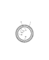
次に、図15に示した変形例に於て、44は小凸条50の切欠部(無存在部)であって、複数の切欠部44によって、小凸条50は円弧状に分断形成され、従って、この分断円弧状の小凸条50が、外周面14側からアルミニウム管4(又は銅管40)に食い込んだ状態で、管回転防止機能を発揮する。即ち、図14(B)の食い込んだ状態では、周方向位置で小凸条50が存在する部位と存在しない部位が交互に形成され、従って、管4,40と、スリーブ7とは、相対的に軸心廻りに回転せず、管4,40の回転は確実に防止される。これによって、配管完了後に、回転トルク(外力)が管4,40に作用したとしても、管4,40が回転せず、これによって、図14(B)に示すように食い込んだ薄壁部13と管外周面14との間を通っての流体の外部漏洩が防止できる。
Next, in the modification shown in FIG. 15, reference numeral 44 denotes a cutout portion (non-existing portion) of the small protrusion 50, and the small protrusion 50 is divided into an arc shape by the plurality of cutout portions 44. Therefore, in the state in which this segmented arc-shaped small ridge 50 bites into the aluminum tube 4 (or the copper tube 40) from the outer peripheral surface 14 side, the tube rotation preventing function is exhibited. That is, in the bitten state of FIG. 14B, the portions where the small ridges 50 are present and the portions where the small ridges 50 are not present are alternately formed in the circumferential position, so that the tubes 4 and 40 and the sleeve 7 are relatively Therefore, the tubes 4 and 40 are reliably prevented from rotating. As a result, even if rotational torque (external force) acts on the pipes 4 and 40 after completion of the piping, the pipes 4 and 40 do not rotate, and thus the thin wall portion 13 that has digged in as shown in FIG. And external leakage of the fluid passing between the pipe outer peripheral surface 14 can be prevented.
そして、図11~図15の各実施の形態に於て、凹周溝9の本数は、2本が最も好ましい。しかしながら、図11~図15に於ては、少なくとも1本の凹周溝9の溝底薄壁部13には、耐引抜力増強機能を発揮する小凸条50を具備している。
追加説明すれば、図11~図14の各実施例の形態では、1本の凹周溝9の場合には、その溝底薄壁部13には必ず小凸条50を有し、また、2本の凹周溝9の場合には、1本又は2本がその溝底薄壁部13に小凸条50を有し、3本の凹周溝9の場合には、1本又は2本若しくは3本が、溝底薄壁部13に小凸条50を有する。さらに、図15に示したような切欠部44を有する小凸条50を、上述の1本又は複数本凹周溝9の薄壁部13に形成するも自由である。 In each of the embodiments shown in FIGS. 11 to 15, the number of the concavecircumferential grooves 9 is most preferably two. However, in FIG. 11 to FIG. 15, the groove bottom thin wall portion 13 of at least one concave circumferential groove 9 is provided with a small ridge 50 that exhibits a function of enhancing the pull-out resistance.
If it explains in addition, in the form of each example of Drawing 11-Drawing 14, in the case of one concave circumference groove 9, the groove bottom thin wall part 13 always has small convex line 50, In the case of two concave circumferential grooves 9, one or two have small convex stripes 50 on the groove bottom thin wall portion 13, and in the case of three concave circumferential grooves 9, one or two Three or three of them have small ridges 50 on the groove bottom thin wall portion 13. Further, it is also possible to freely form the small ridges 50 having the notches 44 as shown in FIG. 15 in the thin wall portion 13 of the one or more concave circumferential grooves 9 described above.
追加説明すれば、図11~図14の各実施例の形態では、1本の凹周溝9の場合には、その溝底薄壁部13には必ず小凸条50を有し、また、2本の凹周溝9の場合には、1本又は2本がその溝底薄壁部13に小凸条50を有し、3本の凹周溝9の場合には、1本又は2本若しくは3本が、溝底薄壁部13に小凸条50を有する。さらに、図15に示したような切欠部44を有する小凸条50を、上述の1本又は複数本凹周溝9の薄壁部13に形成するも自由である。 In each of the embodiments shown in FIGS. 11 to 15, the number of the concave
If it explains in addition, in the form of each example of Drawing 11-
ところで、本発明の上述の圧縮変形用スリーブ7は、「短円筒型」である点が一つの特徴であり、ここで「短円筒型」とは、外径寸法をDとし、長さ寸法をLとすると、 0.5≦L/D≦ 3.0を言うものと定義する。従って、本発明の特徴の一つは、このような短円筒型の円形内周面が、圧縮力Fを受けて、凹周溝底薄壁部13がラジアル内方向へ突出する塑性変形を起こして、挿入されているアルミニウム管4又は銅管40の外周面14側から、安定したU字状に食い込み、抜け止めし、その際、小凸条50は、抜止めに対する抵抗力を増大させる耐引抜力増強機能を発揮する構成である。「短円筒型」のスリーブ7は、未圧縮状態から圧縮状態へと、常に安定姿勢を保持するので、局部的な(小さな)凹周溝底薄壁部13は、図1から図2のように、又は、図5から図6のように、若しくは、図11から図12等のように、さらに、図14(A)から(B)のように、安定した塑性変形の途中姿勢を保ちつつ、最終的な管食い込み塑性変形を行うことができる。
なお、凹周溝9はU字状であれば、図示のアールが大きいU字状以外に、四角張ったU字状や、溝奥部が膨出状又はV状であっても良い。 By the way, the above-mentionedcompression deformation sleeve 7 of the present invention is characterized in that it is a “short cylindrical type”. Here, the “short cylindrical type” means that an outer diameter dimension is D and a length dimension is D. When L is defined, 0.5 ≦ L / D ≦ 3.0 is defined. Accordingly, one of the features of the present invention is that such a short cylindrical circular inner peripheral surface receives a compressive force F and causes plastic deformation in which the concave peripheral groove bottom thin wall portion 13 protrudes radially inward. Then, from the outer peripheral surface 14 side of the inserted aluminum tube 4 or copper tube 40, it bites into a stable U-shape and prevents it from coming off. At this time, the small ridge 50 has a resistance to increase the resistance against retaining. This is a configuration that exerts a pulling force enhancing function. Since the “short cylindrical type” sleeve 7 always maintains a stable posture from an uncompressed state to a compressed state, the local (small) concave groove bottom thin wall portion 13 is as shown in FIGS. In addition, as shown in FIGS. 5 to 6, or as shown in FIGS. 11 to 12, etc., as shown in FIGS. 14 (A) to 14 (B), a stable midway posture of plastic deformation is maintained. The final pipe biting plastic deformation can be performed.
In addition, as long as the concavecircumferential groove 9 is U-shaped, in addition to the U-shaped having a large rounded shape, a square U-shape or a bulging or V-shaped groove may be used.
なお、凹周溝9はU字状であれば、図示のアールが大きいU字状以外に、四角張ったU字状や、溝奥部が膨出状又はV状であっても良い。 By the way, the above-mentioned
In addition, as long as the concave
次に、図11~図13に於て、内鍔部28の断面形状が、図3(D)や図7(B)と相違しているので、その点について説明する。
内鍔部28の内端面28aは、(管4(40)の肉厚寸法と略等しい)段差寸法Hを有する軸心直交平面状段付面が該当する。そして、傾斜角度θのテーパ面19の傾斜線は、(折曲り部無しで)直線状として内鍔部28の外端面の一部を形成し、その傾斜線の内径方向端部19Cは、軸心直交平面部28bに連結している(図13参照)。 Next, in FIGS. 11 to 13, the cross-sectional shape of theinner collar portion 28 is different from those in FIGS. 3D and 7B, and this will be described.
Theinner end surface 28a of the inner flange portion 28 corresponds to an axially orthogonal planar stepped surface having a step size H (substantially equal to the thickness of the tube 4 (40)). The inclined line of the tapered surface 19 with the inclination angle θ forms a part of the outer end surface of the inner flange portion 28 (without a bent portion), and the inner end portion 19C of the inclined line has a shaft It connects with the center orthogonal plane part 28b (refer FIG. 13).
内鍔部28の内端面28aは、(管4(40)の肉厚寸法と略等しい)段差寸法Hを有する軸心直交平面状段付面が該当する。そして、傾斜角度θのテーパ面19の傾斜線は、(折曲り部無しで)直線状として内鍔部28の外端面の一部を形成し、その傾斜線の内径方向端部19Cは、軸心直交平面部28bに連結している(図13参照)。 Next, in FIGS. 11 to 13, the cross-sectional shape of the
The
このように、内鍔部28がスリーブ7に付加されていることによって、テーパ面19がテーパ面17に対して強く(図12のように)圧接した際に、スリーブ7の端部18の肉厚を増加したことに伴う補強作用によって、過大な拡径塑性変形を防止し、しかも、さらなる螺進によって一層強くテーパ面19,17が圧接した際には、前記軸心直交平面部28bが、継手本体1の先端面16Aに当接して、ストッパ作用によって、袋ナット3の過大螺進を防止し、かつ、過大な拡径塑性変形を確実に防止する。即ち、図例では、内鍔部28は、その肉厚(断面積)増加に伴う補強作用、及び、先端面16Aに当接する段差状の軸心直交平面部28bによるストッパ作用によって、端部18の拡径塑性変形(袋ナット3の過大螺進)を阻止できる。
As described above, when the inner flange portion 28 is added to the sleeve 7, when the tapered surface 19 is strongly pressed against the tapered surface 17 (as shown in FIG. 12), the thickness of the end portion 18 of the sleeve 7 is increased. The reinforcing action associated with the increase in thickness prevents excessive diameter-expanding plastic deformation, and when the tapered surfaces 19 and 17 are further pressed against each other by further screwing, the axis orthogonal plane portion 28b is By abutting against the distal end surface 16A of the joint main body 1 and the stopper action, the cap nut 3 is prevented from excessively screwing, and excessively large diameter plastic deformation is reliably prevented. That is, in the illustrated example, the inner flange portion 28 has an end portion 18 due to a reinforcing action accompanying an increase in the thickness (cross-sectional area) and a stopper action by the step-shaped axially orthogonal plane portion 28b contacting the tip face 16A. Can be prevented from expanding (excessive screwing of the cap nut 3).
なお、U字状凹周溝9の本数は、2本が最も好ましい。U字状凹周溝9が1本では、凹周溝底薄壁部13が塑性変形する際、アルミニウム管4との間ですべりを生じやすく(ずれやすく)、パイプの軸心方向の同一の位置に食込ませることが難しいこともあり、3本では、各U字状凹周溝9間に不必要なストレス(内部応力)が残る虞れがあるからである。なお、本発明に於て、「アルミニウム」には、アルミニウム合金を含むものとし、また、「銅」には、銅系合金を含むものとする。
The number of U-shaped concave circumferential grooves 9 is most preferably two. When the U-shaped concave circumferential groove 9 is one, when the concave circumferential groove bottom thin wall portion 13 is plastically deformed, slippage easily occurs between the aluminum pipe 4 (displacement easily), and the same in the axial direction of the pipe. This is because it may be difficult to bite into the position, and in the case of three, unnecessary stress (internal stress) may remain between the U-shaped concave grooves 9. In the present invention, “aluminum” includes an aluminum alloy, and “copper” includes a copper-based alloy.
本発明は、設計変更可能であって、図5,図6の実施形態に、カバー部材24を介装しても自由である(図示省略)。さらに、圧縮変形用スリーブ7が、外周面8に1本又は3本の凹周溝9を有するも良い。また、圧縮変形用スリーブ7が、内周面11に1本のシール溝22を有するも良い。また、袋ナット3の全表面に樹脂21を塗装するも良い。
The design of the present invention can be changed, and the cover member 24 can be interposed in the embodiment shown in FIGS. 5 and 6 (not shown). Further, the compression deformation sleeve 7 may have one or three concave circumferential grooves 9 on the outer peripheral surface 8. The compression deformation sleeve 7 may have one seal groove 22 on the inner peripheral surface 11. Further, the resin 21 may be coated on the entire surface of the cap nut 3.
以上のように、本発明は、袋ナット3の内部に収納されると共に、外周面8に凹周溝9を有する円筒形状の圧縮変形用スリーブ7を具備し、圧縮変形スリーブ7は、凹周溝9の奥部に凹周溝底薄壁部13が形成され、袋ナット3の螺進によってアキシャル方向の圧縮力Fを受けて、凹周溝9の幅寸法Wが減少しつつ凹周溝底薄壁部13がラジアル内方向へ突出するように塑性変形して、挿入されているアルミニウム管4の外周面14側から食い込んでアルミニウム管4の抜止めをするように構成したので、迅速に強力な接続(配管)作業を行い得る。さらに、塑性加工が難しいアルミニウム管4の端部にフレア加工を施す必要がなく、作業効率が良い。また、部品点数が少なく、部品形状がシンプルであって、容易に組立てることができる。
As described above, the present invention includes the cylindrical compression deformation sleeve 7 which is accommodated in the cap nut 3 and has the concave circumferential groove 9 on the outer peripheral surface 8, and the compression deformation sleeve 7 has a concave circumference. A concave groove bottom thin wall portion 13 is formed in the inner part of the groove 9, receives the compressive force F in the axial direction by the screw nut 3 being screwed, and decreases the width W of the concave groove 9 while reducing the width dimension W of the concave circumferential groove 9. The bottom thin wall portion 13 is plastically deformed so as to protrude radially inward, and is configured to bite in from the outer peripheral surface 14 side of the inserted aluminum tube 4 to prevent the aluminum tube 4 from being removed. Strong connection (pipe) work can be performed. Furthermore, it is not necessary to perform a flaring process on the end of the aluminum tube 4 which is difficult to be plastically processed, and the working efficiency is good. Further, the number of parts is small, the part shape is simple, and it can be easily assembled.
また、袋ナット3の内部に収納されると共に、外周面8に凹周溝9を有する円筒形状の圧縮変形用スリーブ7を具備し、圧縮変形スリーブ7は、凹周溝9の奥部には、凹周溝底薄壁部13が形成され、袋ナット3の螺進によってアキシャル方向の圧縮力Fを受けて、凹周溝9の幅寸法Wが減少しつつ凹周溝底薄壁部13がラジアル内方向へ突出するように塑性変形して、挿入されている銅管40の外周面14側から食い込んで銅管40の抜止めをするように構成したので、迅速に強力な接続(配管)作業を行い得る。さらに、銅管40の端部にフレア加工を施す必要がなく、作業効率が良い。また、部品点数が少なく、部品形状がシンプルであって、容易に組立てることができる。
また、圧縮変形スリーブ7の内周面11は、凹周溝底薄壁部13及びその近傍に対応した領域45に於て、略平滑状の円周面形状に形成されているので、管4(40)の外周面に対して安定した塑性変形を行うことができる。 A cylindricalcompression deformation sleeve 7 having a concave groove 9 on the outer peripheral surface 8 is housed inside the cap nut 3, and the compression deformation sleeve 7 is provided at the back of the concave peripheral groove 9. The concave circumferential groove bottom thin wall portion 13 is formed, receives the compressive force F in the axial direction as the cap nut 3 is screwed, and the concave circumferential groove bottom thin wall portion 13 decreases while the width dimension W of the concave circumferential groove 9 decreases. Is deformed so as to protrude radially inward, and is inserted from the outer peripheral surface 14 side of the inserted copper pipe 40 to prevent the copper pipe 40 from being removed. ) Work can be done. Furthermore, it is not necessary to perform a flaring process on the end of the copper tube 40, and the working efficiency is good. Further, the number of parts is small, the part shape is simple, and it can be easily assembled.
Further, since the innerperipheral surface 11 of the compression deformation sleeve 7 is formed in a substantially smooth circumferential surface shape in the region 45 corresponding to the concave peripheral groove bottom thin wall portion 13 and the vicinity thereof, the tube 4 Stable plastic deformation can be performed on the outer peripheral surface of (40).
また、圧縮変形スリーブ7の内周面11は、凹周溝底薄壁部13及びその近傍に対応した領域45に於て、略平滑状の円周面形状に形成されているので、管4(40)の外周面に対して安定した塑性変形を行うことができる。 A cylindrical
Further, since the inner
また、雄ネジ付き継手本体1と、継手本体1の雄ネジ2に螺着される袋ナット3と、を備え、アルミニウム管4を接続する(冷媒用等の)管継手構造に於て、袋ナット3の内部収納空間10に収納されるとともに、外周面8に凹周溝9を有し、袋ナット3と継手本体1の雄ネジ2を螺着させる際に継手本体1と袋ナット3からアキシャル方向の圧縮力Fを受けて、凹周溝底薄壁部13がラジアル内方向へ塑性変形して、挿入されているアルミニウム管4の外周面14側から食い込んで抜止めする圧縮変形用スリーブ7を有するので、迅速に強力な接続(配管)作業を行い得る。さらに、アルミニウム管4にフレア加工を施す必要がなく、作業効率が良い。また、部品点数が少なく、部品形状がシンプルであって、容易に組立てることができる。
また、上記圧縮変形用スリーブ7は、アルミニウム又はアルミニウム層を被覆した銅からなるので、アルミニウム管4に対して電蝕の心配がなく好ましい。 In addition, in a pipe joint structure (for a refrigerant or the like) that includes ajoint body 1 with a male thread and a cap nut 3 that is screwed onto a male thread 2 of the joint body 1 and that connects an aluminum pipe 4 (for a refrigerant or the like). The nut 3 is housed in the internal storage space 10 and has a concave circumferential groove 9 on the outer peripheral surface 8. When the cap nut 3 and the male screw 2 of the joint body 1 are screwed together, the joint body 1 and the cap nut 3 The sleeve for compression deformation that receives the compressive force F in the axial direction and plastically deforms the concave circumferential groove bottom thin wall portion 13 radially inward, and bites in from the outer peripheral surface 14 side of the inserted aluminum tube 4 to prevent it from being removed. 7, it is possible to quickly perform a strong connection (pipe) operation. Furthermore, there is no need to flare the aluminum tube 4, and the working efficiency is good. Further, the number of parts is small, the part shape is simple, and it can be easily assembled.
Thecompression deformation sleeve 7 is preferably made of aluminum or copper coated with an aluminum layer, so that there is no fear of electric corrosion on the aluminum tube 4.
また、上記圧縮変形用スリーブ7は、アルミニウム又はアルミニウム層を被覆した銅からなるので、アルミニウム管4に対して電蝕の心配がなく好ましい。 In addition, in a pipe joint structure (for a refrigerant or the like) that includes a
The
また、雄ネジ付き継手本体1と、継手本体1の雄ネジ2に螺着される袋ナット3と、を備え、銅管40を接続する(冷媒用等の)管継手構造に於て、袋ナット3の内部収納空間10に収納されると共に、外周面8に凹周溝9を有し、袋ナット3と継手本体1の雄ネジ2を螺着させる際に継手本体1と袋ナット3からアキシャル方向の圧縮力Fを受けて、凹周溝底薄壁部13がラジアル内方向へ塑性変形して、挿入されている銅管40の外周面14側から食い込んで抜止めする圧縮変形用スリーブ7を有するので、従来の銅管端部へのフレア加工が全く不要となり、迅速な配管作業を行い得て、作業能率の向上を図り得て、かつ、強力な接続完了の構造となる。さらに、部品点数が少なく、部品形状もシンプルとなる。
In a pipe joint structure (for a refrigerant or the like) that includes a joint body 1 with a male thread and a cap nut 3 that is screwed onto the male thread 2 of the joint body 1 and connects a copper pipe 40 (for a refrigerant or the like). The nut 3 is housed in the internal housing space 10 and has a concave circumferential groove 9 on the outer peripheral surface 8. When the cap nut 3 and the male screw 2 of the joint body 1 are screwed together, the joint body 1 and the cap nut 3 In response to the compressive force F in the axial direction, the concave circumferential groove bottom thin wall portion 13 is plastically deformed radially inward and bites in from the outer peripheral surface 14 side of the inserted copper tube 40 to prevent it from being removed. Therefore, the conventional flare processing to the end of the copper pipe is completely unnecessary, a quick piping work can be performed, the work efficiency can be improved, and a powerful connection complete structure is obtained. Furthermore, the number of parts is small and the part shape is simple.
また、圧縮変形用スリーブ7は、銅からなるので、銅管40に対して、電蝕の心配もなくなる。
また、圧縮変形用スリーブ7の内周面11に予め一体にシール層12を有して、食い込みの際に密封状態となるように構成したので、シール性が良好である。
また、圧縮変形用スリーブ7が内周面11にシール溝22を有し、シール溝22内にシール材23を内装したので、シール性をより向上・安定させることができる。なお、パイプ外周面と、袋ナット3の外端面26の隅部Zには雨水等が溜りやすいが、絶縁性樹脂21を被覆すれば、パイプがアルミニウムから成り、かつ、継手本体1及び袋ナット3が真鍮等のアルミニウムとは異なる金属から成っていても、異種金属の間での電蝕の発生を防止することができる。
また、袋ナットの内周面と、圧縮変形用スリーブの外周面との間に、相対的回転滑り助長用円筒状カバー部材を介在させた構成とすることによって、袋ナット3の内周面3Bと、スリーブ7の外周面との間が軽く回転して、最終的にアルミニウム管4又は銅管40が捩れるという問題を解決して、確実に配管接続作業が容易となる。 Further, since thecompression deformation sleeve 7 is made of copper, there is no fear of electric corrosion with respect to the copper tube 40.
Further, since theseal layer 12 is integrally provided in advance on the inner peripheral surface 11 of the compression deformation sleeve 7 so as to be in a sealed state when biting in, the sealing performance is good.
Further, since thecompression deformation sleeve 7 has the seal groove 22 on the inner peripheral surface 11 and the seal member 23 is housed in the seal groove 22, the sealing performance can be further improved and stabilized. In addition, although rainwater etc. are easy to collect in the pipe outer periphery and the corner Z of the outer end surface 26 of the cap nut 3, if the insulating resin 21 is covered, the pipe is made of aluminum, and the joint body 1 and the cap nut Even if 3 is made of a metal different from aluminum such as brass, it is possible to prevent the occurrence of electrolytic corrosion between different metals.
Further, the innerperipheral surface 3B of the cap nut 3 is configured by interposing a cylindrical cover member for assisting relative rotational slippage between the inner peripheral surface of the cap nut and the outer peripheral surface of the compression deformation sleeve. Then, the problem that the aluminum tube 4 or the copper tube 40 is finally twisted by rotating lightly between the sleeve 7 and the outer peripheral surface of the sleeve 7 is surely facilitated, and the pipe connection work is surely facilitated.
また、圧縮変形用スリーブ7の内周面11に予め一体にシール層12を有して、食い込みの際に密封状態となるように構成したので、シール性が良好である。
また、圧縮変形用スリーブ7が内周面11にシール溝22を有し、シール溝22内にシール材23を内装したので、シール性をより向上・安定させることができる。なお、パイプ外周面と、袋ナット3の外端面26の隅部Zには雨水等が溜りやすいが、絶縁性樹脂21を被覆すれば、パイプがアルミニウムから成り、かつ、継手本体1及び袋ナット3が真鍮等のアルミニウムとは異なる金属から成っていても、異種金属の間での電蝕の発生を防止することができる。
また、袋ナットの内周面と、圧縮変形用スリーブの外周面との間に、相対的回転滑り助長用円筒状カバー部材を介在させた構成とすることによって、袋ナット3の内周面3Bと、スリーブ7の外周面との間が軽く回転して、最終的にアルミニウム管4又は銅管40が捩れるという問題を解決して、確実に配管接続作業が容易となる。 Further, since the
Further, since the
Further, since the
Further, the inner
本発明は、袋ナット3の内部に収納されると共に、外周面8に凹周溝9を有する円筒形状の圧縮変形用スリーブ7を具備し、該圧縮変形スリーブ7は、未圧縮状態では、上記凹周溝9の奥部には、凹周溝底薄壁部13が形成され、かつ、上記凹周溝底薄壁部13はスリーブ内周面側に小凸条50が形成され、上記袋ナット3の螺進によってアキシャル方向の圧縮力Fを受けて、上記凹周溝9の幅寸法Wが減少しつつ上記凹周溝底薄壁部13がラジアル内方向へ突出するように塑性変形して、挿入されているアルミニウム管4の外周面14側から食い込んで該アルミニウム管4の抜止めをするように構成し、かつ、上記小凸条50は、抜止めに対する抵抗力を増大させる耐引抜力増強機能を発揮するように構成したので、迅速に強力な接続(配管)作業を行い得る。さらに、アルミニウム管4にフレア加工を施す必要がなく、作業効率が良い。また、部品点数が少なく、部品形状がシンプルであって、容易に組立てることができる。特に、凹周溝底壁部13と小凸条50の共働によって、耐引抜力は著しく強大である。
The present invention includes a cylindrical compression deformation sleeve 7 which is housed inside the cap nut 3 and has a concave circumferential groove 9 on the outer peripheral surface 8. A concave groove bottom thin wall portion 13 is formed at the back of the concave groove 9, and the concave groove bottom thin wall portion 13 is formed with a small protrusion 50 on the sleeve inner peripheral surface side. When the nut 3 is screwed, it receives a compressive force F in the axial direction, and is plastically deformed so that the concave groove bottom thin wall portion 13 projects radially inward while the width dimension W of the concave groove 9 decreases. The aluminum tube 4 is inserted into the outer peripheral surface 14 side so as to prevent the aluminum tube 4 from being pulled out, and the small protrusion 50 has a resistance to pulling that increases resistance to the retaining. Since it is configured to demonstrate the power enhancement function, it can quickly and strongly connect ( Tube) capable of performing the work. Furthermore, there is no need to flare the aluminum tube 4, and the working efficiency is good. Further, the number of parts is small, the part shape is simple, and it can be easily assembled. In particular, the pull-out resistance is remarkably strong by the cooperation of the concave circumferential groove bottom wall 13 and the small ridges 50.
また、袋ナット3の内部に収納されると共に、外周面8に凹周溝9を有する円筒形状の圧縮変形用スリーブ7を具備し、該圧縮変形スリーブ7は、未圧縮状態では、上記凹周溝9の奥部には、凹周溝底薄壁部13が形成され、かつ、上記凹周溝底薄壁部13はスリーブ内周面側に小凸条50が形成され、上記袋ナット3の螺進によってアキシャル方向の圧縮力Fを受けて、上記凹周溝9の幅寸法Wが減少しつつ上記凹周溝底薄壁部13がラジアル内方向へ突出するように塑性変形して、挿入されている銅管40の外周面14側から食い込んで該銅管40の抜止めをするように構成し、かつ、上記小凸条50は、抜止めに対する抵抗力を増大させる耐引抜力増強機能を発揮するように構成したので、従来の銅管端部へのフレア加工が全く不要となり、迅速な配管作業を行い得て、作業能率の向上を図り得て、かつ、強力な接続完了の構造となる。さらに、部品点数が少なく、部品形状もシンプルとなる。特に、凹周溝底壁部13と小凸条50の共働によって、耐引抜力は著しく強大である。
In addition, a cylindrical compression deformation sleeve 7 which is housed inside the cap nut 3 and has a concave groove 9 on the outer peripheral surface 8 is provided. A concave circumferential groove bottom thin wall portion 13 is formed in the inner portion of the groove 9, and the concave circumferential groove bottom thin wall portion 13 is formed with a small protrusion 50 on the sleeve inner circumferential surface side. Axial compression force F is received by the screwing, and the concave groove bottom thin wall portion 13 is plastically deformed so as to protrude radially inward while the width dimension W of the concave groove 9 is reduced. The structure is such that the inserted copper tube 40 bites in from the outer peripheral surface 14 side to prevent the copper tube 40 from being pulled out, and the small protrusion 50 has an increased resistance to pulling that increases the resistance to the retaining. Since it is configured to demonstrate its functions, conventional flare processing to the end of the copper tube is completely unnecessary It becomes to obtain perform quick plumbing to give work to improve work efficiency, and a structure of a strong connection completion. Furthermore, the number of parts is small and the part shape is simple. In particular, the pull-out resistance is remarkably strong by the cooperation of the concave circumferential groove bottom wall 13 and the small ridges 50.
また、上記小凸条50は複数の切欠部44によって、円弧状に分断形成され、該小凸条50は上記外周面14側から食い込んだ状態で、管回転防止機能を発揮するよう構成されているので、アキシャル方向の圧縮力Fを受けてスリーブ7が塑性変形すると同時に、管4,40の回転が防止されて、密封性が低下することを阻止でき、長期間にわたって優れた密封性能を発揮する。
The small ridges 50 are formed in a circular arc shape by a plurality of notches 44, and the small ridges 50 are configured to exert a tube rotation preventing function while being bitten from the outer peripheral surface 14 side. As a result, the sleeve 7 is plastically deformed by receiving the compressive force F in the axial direction, and at the same time the rotation of the tubes 4 and 40 can be prevented and the sealing performance can be prevented from being lowered, and excellent sealing performance is exhibited over a long period of time. To do.
1 (雄ネジ付き)継手本体
2 雄ネジ
3 袋ナット
4 アルミニウム管
7 圧縮変形用スリーブ
8 外周面
9 凹周溝
10 内部収納空間
11 内周面
12 シール層
13 凹周溝底薄壁部
14 外周面
22 シール溝
23 シール材
24 カバー部材
40 銅管
44 切欠部
45 領域
50 小凸条
F 圧縮力(締付力)
W 幅寸法 DESCRIPTION OF SYMBOLS 1 (With external thread) Jointmain body 2 Male thread 3 Cap nut 4 Aluminum pipe 7 Compression deformation sleeve 8 Outer peripheral surface 9 Concave groove 10 Internal storage space 11 Inner peripheral surface 12 Seal layer 13 Concave groove bottom thin wall part 14 Outer periphery Surface 22 Seal groove 23 Seal material 24 Cover member 40 Copper pipe 44 Notch 45 Area 50 Small convex stripe F Compression force (clamping force)
W width dimension
2 雄ネジ
3 袋ナット
4 アルミニウム管
7 圧縮変形用スリーブ
8 外周面
9 凹周溝
10 内部収納空間
11 内周面
12 シール層
13 凹周溝底薄壁部
14 外周面
22 シール溝
23 シール材
24 カバー部材
40 銅管
44 切欠部
45 領域
50 小凸条
F 圧縮力(締付力)
W 幅寸法 DESCRIPTION OF SYMBOLS 1 (With external thread) Joint
W width dimension
Claims (14)
- 袋ナット(3)の内部に収納されると共に、外周面(8)に凹周溝(9)を有する円筒形状の圧縮変形用スリーブ(7)を具備し、
該圧縮変形スリーブ(7)は、上記凹周溝(9)の奥部に凹周溝底薄壁部(13)が形成され、
上記袋ナット(3)の螺進によってアキシャル方向の圧縮力(F)を受けて、上記凹周溝(9)の幅寸法(W)が減少しつつ上記凹周溝底薄壁部(13)がラジアル内方向へ突出するように塑性変形して、挿入されているアルミニウム管(4)の外周面(14)側から食い込んで該アルミニウム管(4)の抜止めをするように構成したことを特徴とする管継手構造。 A cylindrical compression deformation sleeve (7) having a concave groove (9) on the outer peripheral surface (8) is housed in the cap nut (3), and
The compression deformation sleeve (7) has a concave circumferential groove bottom thin wall portion (13) formed at the back of the concave circumferential groove (9).
An axial compression force (F) is received by screwing of the cap nut (3), and the width (W) of the concave circumferential groove (9) is reduced, while the concave circumferential groove bottom thin wall portion (13). Is plastically deformed so as to protrude radially inward, and is inserted from the outer peripheral surface (14) side of the inserted aluminum tube (4) to prevent the aluminum tube (4) from being removed. Characteristic pipe joint structure. - 袋ナット(3)の内部に収納されると共に、外周面(8)に凹周溝(9)を有する円筒形状の圧縮変形用スリーブ(7)を具備し、
該圧縮変形スリーブ(7)は、上記凹周溝(9)の奥部には、凹周溝底薄壁部(13)が形成され、
上記袋ナット(3)の螺進によってアキシャル方向の圧縮力(F)を受けて、上記凹周溝(9)の幅寸法(W)が減少しつつ上記凹周溝底薄壁部(13)がラジアル内方向へ突出するように塑性変形して、挿入されている銅管(40)の外周面(14)側から食い込んで該銅管(40)の抜止めをするように構成したことを特徴とする管継手構造。 A cylindrical compression deformation sleeve (7) having a concave groove (9) on the outer peripheral surface (8) is housed in the cap nut (3), and
The compression deformation sleeve (7) has a concave circumferential groove bottom thin wall portion (13) formed at the back of the concave circumferential groove (9).
An axial compression force (F) is received by screwing of the cap nut (3), and the width (W) of the concave circumferential groove (9) is reduced, while the concave circumferential groove bottom thin wall portion (13). Is deformed plastically so as to protrude radially inward, and is inserted from the outer peripheral surface (14) side of the inserted copper pipe (40) to prevent the copper pipe (40) from being removed. Characteristic pipe joint structure. - 上記圧縮変形スリーブ(7)の内周面(11)は、上記凹周溝底薄壁部(13)及びその近傍に対応した領域(45)に於て、略平滑状の円周面形状に形成されている請求項1又は2記載の管継手構造。 The inner circumferential surface (11) of the compression deformation sleeve (7) has a substantially smooth circumferential surface shape in the concave circumferential groove bottom thin wall portion (13) and a region (45) corresponding to the vicinity thereof. The pipe joint structure according to claim 1 or 2, wherein the pipe joint structure is formed.
- 雄ネジ付き継手本体(1)と、該継手本体(1)の雄ネジ(2)に螺着される袋ナット(3)と、を備え、アルミニウム管(4)を接続する管継手構造に於て、
上記袋ナット(3)の内部収納空間(10)に収納されると共に、外周面(8)に凹周溝(9)を有し、上記袋ナット(3)と上記継手本体(1)の雄ネジ(2)を螺着させる際に上記継手本体(1)と上記袋ナット(3)からアキシャル方向の圧縮力(F)を受けて、凹周溝底薄壁部(13)がラジアル内方向へ塑性変形して、挿入されている上記アルミニウム管(4)の外周面(14)側から食い込んで抜止めする圧縮変形用スリーブ(7)を有することを特徴とする管継手構造。 In a pipe joint structure comprising a joint body (1) with a male thread and a cap nut (3) screwed to the male thread (2) of the joint body (1), and connecting an aluminum pipe (4) And
The cap nut is housed in the internal storage space (10) of the nut (3), has a concave groove (9) on the outer peripheral surface (8), and is a male of the cap nut (3) and the joint body (1). When the screw (2) is screwed, the axially compressive force (F) is received from the joint body (1) and the cap nut (3), so that the concave groove bottom thin wall portion (13) is radially inward. A pipe joint structure characterized by having a compression deformation sleeve (7) which is plastically deformed and bites in from the outer peripheral surface (14) side of the inserted aluminum pipe (4) to prevent it from being removed. - 上記圧縮変形用スリーブ(7)は、アルミニウム又はアルミニウム層を被覆した銅から成る請求項4記載の管継手構造。 The pipe joint structure according to claim 4, wherein the compression deformation sleeve (7) is made of aluminum or copper coated with an aluminum layer.
- 雄ネジ付き継手本体(1)と、該継手本体(1)の雄ネジ(2)に螺着される袋ナット(3)と、を備え、銅管(40)を接続する管継手構造に於て、
上記袋ナット(3)の内部収納空間(10)に収納されると共に、外周面(8)に凹周溝(9)を有し、上記袋ナット(3)と上記継手本体(1)の雄ネジ(2)を螺着させる際に上記継手本体(1)と上記袋ナット(3)からアキシャル方向の圧縮力(F)を受けて、凹周溝底薄壁部(13)がラジアル内方向へ塑性変形して、挿入されている上記銅管(40)の外周面(14)側から食い込んで抜止めする圧縮変形用スリーブ(7)を有することを特徴とする管継手構造。 In a pipe joint structure comprising a joint body (1) with a male thread and a cap nut (3) screwed to the male thread (2) of the joint body (1), and connecting a copper pipe (40) And
The cap nut is housed in the internal storage space (10) of the nut (3), has a concave groove (9) on the outer peripheral surface (8), and is a male of the cap nut (3) and the joint body (1). When the screw (2) is screwed, the axially compressive force (F) is received from the joint body (1) and the cap nut (3), so that the concave groove bottom thin wall portion (13) is radially inward. A pipe joint structure characterized by having a compression deformation sleeve (7) that is plastically deformed and bites in from the outer peripheral surface (14) side of the inserted copper pipe (40) to prevent it from being removed. - 上記圧縮変形用スリーブ(7)は、銅から成る請求項6記載の管継手構造。 The pipe joint structure according to claim 6, wherein the compression deformation sleeve (7) is made of copper.
- 上記凹周溝(9)がU字状である請求項1,2,3,4,5,6又は7記載の管継手構造。 The pipe joint structure according to claim 1, 2, 3, 4, 5, 6 or 7, wherein the concave circumferential groove (9) is U-shaped.
- 上記圧縮変形用スリーブ(7)の内周面(11)に予め一体にシール層(12)を有して、上記食い込みの際に密封状態となるように構成した請求項1,2,3,4,5,6,7又は8記載の管継手構造。 An inner peripheral surface (11) of the compression deformation sleeve (7) has a seal layer (12) integrally in advance, and is configured to be in a sealed state upon the bite. The pipe joint structure according to 4, 5, 6, 7 or 8.
- 上記圧縮変形用スリーブ(7)が内周面(11)にシール溝(22)を有し、該シール溝(22)内にシール材(23)を内装した請求項1,2,3,4,5,6,7,8又は9記載の管継手構造。 The compression deformation sleeve (7) has a seal groove (22) on an inner peripheral surface (11), and a seal material (23) is provided in the seal groove (22). , 5, 6, 7, 8, or 9.
- 上記袋ナット(3)の内周面(3B)と、上記圧縮変形用スリーブ(7)の外周面との間に、相対的回転滑り助長用円筒状カバー部材(24)を介在させた請求項1,2,3,4,5,6,7,8,9又は10記載の管継手構造。 A cylindrical cover member (24) for promoting relative rotational slip is interposed between an inner peripheral surface (3B) of the cap nut (3) and an outer peripheral surface of the compression deformation sleeve (7). A pipe joint structure according to 1, 2, 3, 4, 5, 6, 7, 8, 9 or 10.
- 袋ナット(3)の内部に収納されると共に、外周面(8)に凹周溝(9)を有する円筒形状の圧縮変形用スリーブ(7)を具備し、
該圧縮変形スリーブ(7)は、未圧縮状態では、上記凹周溝(9)の奥部には、凹周溝底薄壁部(13)が形成され、かつ、上記凹周溝底薄壁部(13)はスリーブ内周面側に小凸条(50)が形成され、
上記袋ナット(3)の螺進によってアキシャル方向の圧縮力(F)を受けて、上記凹周溝(9)の幅寸法(W)が減少しつつ上記凹周溝底薄壁部(13)がラジアル内方向へ突出するように塑性変形して、挿入されているアルミニウム管(4)の外周面(14)側から食い込んで該アルミニウム管(4)の抜止めをするように構成し、かつ、上記小凸条(50)は、抜止めに対する抵抗力を増大させる耐引抜力増強機能を発揮するように構成したことを特徴とする管継手構造。 A cylindrical compression deformation sleeve (7) having a concave groove (9) on the outer peripheral surface (8) is housed in the cap nut (3), and
When the compression deformation sleeve (7) is in an uncompressed state, a concave circumferential groove bottom thin wall portion (13) is formed at the back of the concave circumferential groove (9), and the concave circumferential groove bottom thin wall is formed. The portion (13) has a small protrusion (50) formed on the inner peripheral surface side of the sleeve,
An axial compression force (F) is received by screwing of the cap nut (3), and the width (W) of the concave circumferential groove (9) is reduced, while the concave circumferential groove bottom thin wall portion (13). Is plastically deformed so as to protrude radially inward, and is inserted from the outer peripheral surface (14) side of the inserted aluminum pipe (4) to prevent the aluminum pipe (4) from being removed, and The above-mentioned small ridge (50) is constructed so as to exhibit a pulling-out force enhancing function for increasing the resistance against slipping-off. - 袋ナット(3)の内部に収納されると共に、外周面(8)に凹周溝(9)を有する円筒形状の圧縮変形用スリーブ(7)を具備し、
該圧縮変形スリーブ(7)は、未圧縮状態では、上記凹周溝(9)の奥部には、凹周溝底薄壁部(13)が形成され、かつ、上記凹周溝底薄壁部(13)はスリーブ内周面側に小凸条(50)が形成され、
上記袋ナット(3)の螺進によってアキシャル方向の圧縮力(F)を受けて、上記凹周溝(9)の幅寸法(W)が減少しつつ上記凹周溝底薄壁部(13)がラジアル内方向へ突出するように塑性変形して、挿入されている銅管(40)の外周面(14)側から食い込んで該銅管(40)の抜止めをするように構成し、かつ、上記小凸条(50)は、抜止めに対する抵抗力を増大させる耐引抜力増強機能を発揮するように構成したことを特徴とする管継手構造。 A cylindrical compression deformation sleeve (7) having a concave groove (9) on the outer peripheral surface (8) is housed in the cap nut (3), and
When the compression deformation sleeve (7) is in an uncompressed state, a concave circumferential groove bottom thin wall portion (13) is formed at the back of the concave circumferential groove (9), and the concave circumferential groove bottom thin wall is formed. The portion (13) has a small protrusion (50) formed on the inner peripheral surface side of the sleeve,
An axial compression force (F) is received by screwing of the cap nut (3), and the width (W) of the concave circumferential groove (9) is reduced, while the concave circumferential groove bottom thin wall portion (13). Is plastically deformed so as to protrude radially inward, and is inserted from the outer peripheral surface (14) side of the inserted copper pipe (40) to prevent the copper pipe (40) from being removed, and The above-mentioned small ridge (50) is constructed so as to exhibit a pulling-out force enhancing function for increasing the resistance against slipping-off. - 上記小凸条(50)は複数の切欠部(44)によって、円弧状に分断形成され、該小凸条(50)は上記外周面(14)側から食い込んだ状態で、管回転防止機能を発揮するよう構成されている請求項12又は13記載の管継手構造。 The small ridge (50) is divided into an arc shape by a plurality of notches (44), and the small ridge (50) has a function of preventing tube rotation in a state of being bitten from the outer peripheral surface (14) side. The pipe joint structure according to claim 12 or 13, wherein the pipe joint structure is configured to exhibit.
Priority Applications (5)
| Application Number | Priority Date | Filing Date | Title |
|---|---|---|---|
| EP13839851.6A EP2899441B1 (en) | 2012-09-19 | 2013-05-13 | Pipe joint structure |
| CN201380048765.6A CN104620034B (en) | 2012-09-19 | 2013-05-13 | Pipe joint constructs |
| US14/411,254 US20150137517A1 (en) | 2012-09-19 | 2013-05-13 | Pipe joint construction |
| SG11201408371XA SG11201408371XA (en) | 2012-09-19 | 2013-05-13 | Pipe joint construction |
| KR1020147036644A KR20150054717A (en) | 2012-09-19 | 2013-05-13 | Pipe joint structure |
Applications Claiming Priority (6)
| Application Number | Priority Date | Filing Date | Title |
|---|---|---|---|
| JP2012205647 | 2012-09-19 | ||
| JP2012-205647 | 2012-09-19 | ||
| JP2012-245025 | 2012-11-07 | ||
| JP2012245025 | 2012-11-07 | ||
| JP2012262696A JP5276215B1 (en) | 2012-09-19 | 2012-11-30 | Pipe joint structure for refrigerant |
| JP2012-262696 | 2012-11-30 |
Publications (1)
| Publication Number | Publication Date |
|---|---|
| WO2014045632A1 true WO2014045632A1 (en) | 2014-03-27 |
Family
ID=49179264
Family Applications (1)
| Application Number | Title | Priority Date | Filing Date |
|---|---|---|---|
| PCT/JP2013/063279 WO2014045632A1 (en) | 2012-09-19 | 2013-05-13 | Pipe joint structure |
Country Status (7)
| Country | Link |
|---|---|
| US (1) | US20150137517A1 (en) |
| EP (1) | EP2899441B1 (en) |
| JP (2) | JP5276215B1 (en) |
| KR (1) | KR20150054717A (en) |
| CN (1) | CN104620034B (en) |
| SG (1) | SG11201408371XA (en) |
| WO (1) | WO2014045632A1 (en) |
Families Citing this family (16)
| Publication number | Priority date | Publication date | Assignee | Title |
|---|---|---|---|---|
| KR101295523B1 (en) * | 2012-11-08 | 2013-08-12 | 주식회사 비엠티 | A back ferrule with a bellows shaped elastic portion, and a pipe connecting device having the same |
| JP6112842B2 (en) * | 2012-11-30 | 2017-04-12 | 井上スダレ株式会社 | Pipe joint structure |
| JP5503797B1 (en) * | 2013-11-14 | 2014-05-28 | 井上スダレ株式会社 | Pipe joint structure for refrigerant |
| JP5592573B1 (en) * | 2014-01-06 | 2014-09-17 | 井上スダレ株式会社 | Pipe joint structure for refrigerant |
| JP5723470B1 (en) * | 2014-07-15 | 2015-05-27 | 井上スダレ株式会社 | Pipe joint structure for refrigerant |
| JP5736499B1 (en) * | 2014-10-30 | 2015-06-17 | 井上スダレ株式会社 | Pipe joint structure |
| US10094494B2 (en) * | 2015-06-26 | 2018-10-09 | Agilent Technologies, Inc. | Ferrule with features for softening ferrule crush and related methods |
| CN105299346A (en) * | 2015-11-27 | 2016-02-03 | 江苏省绿岛管阀件有限公司 | PP pipe with sealing pipe joint |
| CN105257925A (en) * | 2015-11-27 | 2016-01-20 | 江苏省绿岛管阀件有限公司 | Seal pipe joint for PP pipes |
| JP6276321B2 (en) * | 2016-04-28 | 2018-02-07 | 井上スダレ株式会社 | Pipe joint structure |
| JP2017223277A (en) * | 2016-06-15 | 2017-12-21 | 井上スダレ株式会社 | Pipe joint structure |
| CN107626008A (en) * | 2017-10-31 | 2018-01-26 | 深圳核心医疗器械有限公司 | The outlet connecting mechanism and its assemble method of a kind of artificial blood pump |
| CN108593447A (en) * | 2018-04-20 | 2018-09-28 | 中国石油集团渤海石油装备制造有限公司 | Internal lining pipe water test unit and test method |
| JP6777177B2 (en) | 2019-02-15 | 2020-10-28 | ダイキン工業株式会社 | Units for joint members and air conditioners |
| KR102530653B1 (en) * | 2023-02-27 | 2023-05-09 | 주식회사 우정메카트로닉스 | Valve link assembly |
| CN117738592B (en) * | 2024-02-21 | 2024-04-16 | 胜利油田胜机石油装备有限公司 | Electroplating anti-corrosion oil pipe with sealing structure |
Citations (5)
| Publication number | Priority date | Publication date | Assignee | Title |
|---|---|---|---|---|
| JPH10185027A (en) * | 1996-11-05 | 1998-07-14 | Fujii Gokin Seisakusho Co Ltd | Pipe connection device |
| JP2002327876A (en) * | 2001-03-01 | 2002-11-15 | Kitz Corp | Joining structure for coupling and valve and thin pipe coupling |
| JP2002340250A (en) * | 2001-05-21 | 2002-11-27 | Hitachi Metals Ltd | Mechanical pipe joint for metallic pipe |
| JP2005042858A (en) | 2003-07-24 | 2005-02-17 | Mitsubishi Electric Corp | Flare pipe joint structure, and product using the same |
| JP2006329436A (en) * | 2006-09-14 | 2006-12-07 | Tomohito Inoue | Pipe joint |
Family Cites Families (41)
| Publication number | Priority date | Publication date | Assignee | Title |
|---|---|---|---|---|
| US2287889A (en) * | 1940-12-03 | 1942-06-30 | Mueller Co | Lock joint coupling |
| US2466057A (en) * | 1947-02-18 | 1949-04-05 | Somma Raymond | Combined tube connector and tube flarer |
| US2693374A (en) * | 1950-05-05 | 1954-11-02 | Paul D Wurzburger | Pipe coupling with deformable ring for flareless pipe |
| US2693375A (en) * | 1953-01-23 | 1954-11-02 | Paul D Wurzburger | Double-biting ring pipe coupling |
| US2823935A (en) * | 1953-01-23 | 1958-02-18 | Paul D Wurzburger | Pipe coupling with deformable ring for flareless pipe |
| US3120969A (en) * | 1959-05-12 | 1964-02-11 | Parker Hannifin Corp | Flareless tube coupling |
| US3055684A (en) * | 1959-09-01 | 1962-09-25 | Parker Hannifin Corp | Flareless tube coupling |
| US3174778A (en) * | 1962-05-17 | 1965-03-23 | Curtis Mfg Co | Fitting for tubes |
| US3325192A (en) * | 1964-11-19 | 1967-06-13 | Parker Hannifin Corp | Flareless tube coupling nut and ferrule assembly |
| JPS5441124B2 (en) * | 1974-02-01 | 1979-12-06 | ||
| US3879070A (en) * | 1974-04-22 | 1975-04-22 | Carrier Corp | Tube coupling mechanism |
| GB2071799A (en) * | 1980-03-11 | 1981-09-23 | Hepworth Plastics Ltd | Pipe couplings |
| JPS59114718U (en) * | 1983-01-24 | 1984-08-02 | 船舶商事株式会社 | Packaging for holding wires for marine wire-penetrating hardware |
| US4556242A (en) * | 1983-11-25 | 1985-12-03 | Imperial Clevite Inc. | Vibration resistant high pressure tube fitting |
| US4867489A (en) * | 1987-09-21 | 1989-09-19 | Parker Hannifin Corporation | Tube fitting |
| JPH01180088U (en) * | 1988-06-10 | 1989-12-25 | ||
| JPH0243586U (en) * | 1988-09-19 | 1990-03-26 | ||
| US4940263A (en) * | 1988-10-11 | 1990-07-10 | Dormont Manufacturing Company | Fitting for tubing |
| WO1991008414A1 (en) * | 1989-11-23 | 1991-06-13 | Vulcan Australia Limited | Conduit coupling |
| US5217261A (en) * | 1990-04-23 | 1993-06-08 | Aeroquip Corporation | Flareless compression fitting |
| JPH0728462Y2 (en) * | 1992-03-04 | 1995-06-28 | 株式会社日立物流 | Pipe fitting device |
| DE4229502C2 (en) * | 1992-09-04 | 1998-01-22 | Froehlich Manfred | Cutting ring for a pipe connection |
| JPH07248081A (en) * | 1994-03-10 | 1995-09-26 | Fujii Gokin Seisakusho:Kk | Pipe connecting device |
| JPH07248082A (en) * | 1994-03-10 | 1995-09-26 | Fujii Gokin Seisakusho:Kk | Pipe connecting method, and pipe connecting device executing it |
| JPH08135862A (en) * | 1994-11-04 | 1996-05-31 | Fujii Gokin Seisakusho Co Ltd | Pipe joining device and extensible/contractible pipe coupling |
| JP3041477B2 (en) * | 1996-11-05 | 2000-05-15 | 株式会社藤井合金製作所 | Pipe connection device |
| DE19709464C2 (en) * | 1997-03-07 | 2000-03-09 | Voss Armaturen | Pipe fitting with cutting ring for metallic pipes |
| JPH11141760A (en) * | 1997-11-10 | 1999-05-28 | Toyo Fitting Kk | Connecting structure for metal pipe and joint |
| JPH11182767A (en) * | 1997-12-24 | 1999-07-06 | Calsonic Corp | Connecting structure of flexible tube |
| KR100258025B1 (en) * | 1998-02-03 | 2000-06-01 | 박실조 | Pipe connecter |
| JP3592079B2 (en) * | 1998-05-21 | 2004-11-24 | 日本フレックス株式会社 | Seal connector |
| JP2000193157A (en) * | 1998-12-25 | 2000-07-14 | Sankei Seisakusho:Kk | Pipe fitting |
| US6575501B1 (en) * | 1999-03-05 | 2003-06-10 | Valco Instruments Company, Inc. | Tube sealing bushing |
| DE102004026789B4 (en) * | 2004-06-02 | 2008-11-06 | Eaton Fluid Power Gmbh | connecting device |
| CN101379335A (en) * | 2006-01-31 | 2009-03-04 | 大金工业株式会社 | Bite type tube connection structure, tube fitting, valve, closing valve, refrigerating cycle device, hot-water supply device, bite type tube connection method, and on-site tube connection method |
| BRPI0717029A2 (en) * | 2006-08-31 | 2013-10-01 | Titeflex Corp | bending connection for stainless steel corrugated tubes |
| JP5164668B2 (en) * | 2008-05-22 | 2013-03-21 | アロン化成株式会社 | Pipe joint structure, pipe fittings equipped with this |
| DE102009011411B4 (en) * | 2009-03-03 | 2014-09-18 | Neoperl Gmbh | Sanitary hose coupling |
| US8955886B2 (en) * | 2010-12-08 | 2015-02-17 | Yokohama Industries Americas Inc. | Hydraulic ducts and connecting assemblies |
| CN202349430U (en) * | 2011-11-05 | 2012-07-25 | 钟声远 | Snap-ring type pipe connector |
| GB2505946B (en) * | 2012-09-17 | 2020-07-08 | Parker Hannifin Mfg Uk Limited | A compressible coupling |
-
2012
- 2012-11-30 JP JP2012262696A patent/JP5276215B1/en not_active Expired - Fee Related
-
2013
- 2013-03-04 JP JP2013042203A patent/JP5306553B1/en not_active Expired - Fee Related
- 2013-05-13 EP EP13839851.6A patent/EP2899441B1/en active Active
- 2013-05-13 US US14/411,254 patent/US20150137517A1/en not_active Abandoned
- 2013-05-13 SG SG11201408371XA patent/SG11201408371XA/en unknown
- 2013-05-13 WO PCT/JP2013/063279 patent/WO2014045632A1/en active Application Filing
- 2013-05-13 CN CN201380048765.6A patent/CN104620034B/en active Active
- 2013-05-13 KR KR1020147036644A patent/KR20150054717A/en not_active Application Discontinuation
Patent Citations (5)
| Publication number | Priority date | Publication date | Assignee | Title |
|---|---|---|---|---|
| JPH10185027A (en) * | 1996-11-05 | 1998-07-14 | Fujii Gokin Seisakusho Co Ltd | Pipe connection device |
| JP2002327876A (en) * | 2001-03-01 | 2002-11-15 | Kitz Corp | Joining structure for coupling and valve and thin pipe coupling |
| JP2002340250A (en) * | 2001-05-21 | 2002-11-27 | Hitachi Metals Ltd | Mechanical pipe joint for metallic pipe |
| JP2005042858A (en) | 2003-07-24 | 2005-02-17 | Mitsubishi Electric Corp | Flare pipe joint structure, and product using the same |
| JP2006329436A (en) * | 2006-09-14 | 2006-12-07 | Tomohito Inoue | Pipe joint |
Also Published As
| Publication number | Publication date |
|---|---|
| EP2899441B1 (en) | 2019-08-14 |
| JP5306553B1 (en) | 2013-10-02 |
| SG11201408371XA (en) | 2015-01-29 |
| EP2899441A4 (en) | 2016-05-25 |
| US20150137517A1 (en) | 2015-05-21 |
| JP5276215B1 (en) | 2013-08-28 |
| CN104620034B (en) | 2016-11-09 |
| JP2014111949A (en) | 2014-06-19 |
| CN104620034A (en) | 2015-05-13 |
| KR20150054717A (en) | 2015-05-20 |
| JP2014111975A (en) | 2014-06-19 |
| EP2899441A1 (en) | 2015-07-29 |
Similar Documents
| Publication | Publication Date | Title |
|---|---|---|
| WO2014045632A1 (en) | Pipe joint structure | |
| JP5758640B2 (en) | Tube fitting | |
| JP5592573B1 (en) | Pipe joint structure for refrigerant | |
| JP6112842B2 (en) | Pipe joint structure | |
| JP5723470B1 (en) | Pipe joint structure for refrigerant | |
| JP5736499B1 (en) | Pipe joint structure | |
| JP2010223347A (en) | Resin pipe joint | |
| WO2018011906A1 (en) | Pipe joint | |
| JP5523612B1 (en) | Pipe joint structure | |
| JP4789999B2 (en) | Resin pipe fitting | |
| JP2002295756A (en) | Simplified swivel hose joint | |
| JP2014109295A (en) | Pipe joint structure | |
| JP4005114B1 (en) | Flare fastening structure of tube | |
| JP6234785B2 (en) | Fitting | |
| TWI509177B (en) | Pipe joint construction | |
| JP2015135170A (en) | Pipe joint structure for refrigerant | |
| JP5592614B2 (en) | Pipe joint and piping material using the pipe joint | |
| JP5934667B2 (en) | Pipe fitting | |
| JP2010127461A (en) | Resin pipe joint | |
| JP4885201B2 (en) | Resin pipe fitting | |
| KR101579535B1 (en) | Apparatus fixing pipe connector with high pressure fluid for anti-leakage and system thereof | |
| JP5503797B1 (en) | Pipe joint structure for refrigerant | |
| JP5525897B2 (en) | Pipe fitting | |
| JP2010223291A (en) | Resin pipe joint | |
| JP2007321857A (en) | Pipe joint |
Legal Events
| Date | Code | Title | Description |
|---|---|---|---|
| 121 | Ep: the epo has been informed by wipo that ep was designated in this application |
Ref document number: 13839851 Country of ref document: EP Kind code of ref document: A1 |
|
| WWE | Wipo information: entry into national phase |
Ref document number: 14411254 Country of ref document: US |
|
| ENP | Entry into the national phase |
Ref document number: 20147036644 Country of ref document: KR Kind code of ref document: A |
|
| NENP | Non-entry into the national phase |
Ref country code: DE |