WO2014045425A1 - 血糖管理システム - Google Patents
血糖管理システム Download PDFInfo
- Publication number
- WO2014045425A1 WO2014045425A1 PCT/JP2012/074328 JP2012074328W WO2014045425A1 WO 2014045425 A1 WO2014045425 A1 WO 2014045425A1 JP 2012074328 W JP2012074328 W JP 2012074328W WO 2014045425 A1 WO2014045425 A1 WO 2014045425A1
- Authority
- WO
- WIPO (PCT)
- Prior art keywords
- hypoglycemia
- sensor
- blood glucose
- vital
- management system
- Prior art date
- Legal status (The legal status is an assumption and is not a legal conclusion. Google has not performed a legal analysis and makes no representation as to the accuracy of the status listed.)
- Ceased
Links
Images



Classifications
-
- A—HUMAN NECESSITIES
- A61—MEDICAL OR VETERINARY SCIENCE; HYGIENE
- A61B—DIAGNOSIS; SURGERY; IDENTIFICATION
- A61B5/00—Measuring for diagnostic purposes; Identification of persons
- A61B5/145—Measuring characteristics of blood in vivo, e.g. gas concentration or pH-value ; Measuring characteristics of body fluids or tissues, e.g. interstitial fluid or cerebral tissue
- A61B5/14532—Measuring characteristics of blood in vivo, e.g. gas concentration or pH-value ; Measuring characteristics of body fluids or tissues, e.g. interstitial fluid or cerebral tissue for measuring glucose, e.g. by tissue impedance measurement
-
- A—HUMAN NECESSITIES
- A61—MEDICAL OR VETERINARY SCIENCE; HYGIENE
- A61B—DIAGNOSIS; SURGERY; IDENTIFICATION
- A61B5/00—Measuring for diagnostic purposes; Identification of persons
- A61B5/02—Detecting, measuring or recording for evaluating the cardiovascular system, e.g. pulse, heart rate, blood pressure or blood flow
- A61B5/021—Measuring pressure in heart or blood vessels
-
- A—HUMAN NECESSITIES
- A61—MEDICAL OR VETERINARY SCIENCE; HYGIENE
- A61B—DIAGNOSIS; SURGERY; IDENTIFICATION
- A61B5/00—Measuring for diagnostic purposes; Identification of persons
- A61B5/145—Measuring characteristics of blood in vivo, e.g. gas concentration or pH-value ; Measuring characteristics of body fluids or tissues, e.g. interstitial fluid or cerebral tissue
- A61B5/1455—Measuring characteristics of blood in vivo, e.g. gas concentration or pH-value ; Measuring characteristics of body fluids or tissues, e.g. interstitial fluid or cerebral tissue using optical sensors, e.g. spectral photometrical oximeters
- A61B5/14551—Measuring characteristics of blood in vivo, e.g. gas concentration or pH-value ; Measuring characteristics of body fluids or tissues, e.g. interstitial fluid or cerebral tissue using optical sensors, e.g. spectral photometrical oximeters for measuring blood gases
-
- A—HUMAN NECESSITIES
- A61—MEDICAL OR VETERINARY SCIENCE; HYGIENE
- A61M—DEVICES FOR INTRODUCING MEDIA INTO, OR ONTO, THE BODY; DEVICES FOR TRANSDUCING BODY MEDIA OR FOR TAKING MEDIA FROM THE BODY; DEVICES FOR PRODUCING OR ENDING SLEEP OR STUPOR
- A61M5/00—Devices for bringing media into the body in a subcutaneous, intra-vascular or intramuscular way; Accessories therefor, e.g. filling or cleaning devices, arm-rests
- A61M5/14—Infusion devices, e.g. infusing by gravity; Blood infusion; Accessories therefor
- A61M5/168—Means for controlling media flow to the body or for metering media to the body, e.g. drip meters, counters ; Monitoring media flow to the body
- A61M5/172—Means for controlling media flow to the body or for metering media to the body, e.g. drip meters, counters ; Monitoring media flow to the body electrical or electronic
- A61M5/1723—Means for controlling media flow to the body or for metering media to the body, e.g. drip meters, counters ; Monitoring media flow to the body electrical or electronic using feedback of body parameters, e.g. blood-sugar, pressure
-
- G—PHYSICS
- G16—INFORMATION AND COMMUNICATION TECHNOLOGY [ICT] SPECIALLY ADAPTED FOR SPECIFIC APPLICATION FIELDS
- G16H—HEALTHCARE INFORMATICS, i.e. INFORMATION AND COMMUNICATION TECHNOLOGY [ICT] SPECIALLY ADAPTED FOR THE HANDLING OR PROCESSING OF MEDICAL OR HEALTHCARE DATA
- G16H20/00—ICT specially adapted for therapies or health-improving plans, e.g. for handling prescriptions, for steering therapy or for monitoring patient compliance
- G16H20/10—ICT specially adapted for therapies or health-improving plans, e.g. for handling prescriptions, for steering therapy or for monitoring patient compliance relating to drugs or medications, e.g. for ensuring correct administration to patients
- G16H20/17—ICT specially adapted for therapies or health-improving plans, e.g. for handling prescriptions, for steering therapy or for monitoring patient compliance relating to drugs or medications, e.g. for ensuring correct administration to patients delivered via infusion or injection
-
- G—PHYSICS
- G16—INFORMATION AND COMMUNICATION TECHNOLOGY [ICT] SPECIALLY ADAPTED FOR SPECIFIC APPLICATION FIELDS
- G16H—HEALTHCARE INFORMATICS, i.e. INFORMATION AND COMMUNICATION TECHNOLOGY [ICT] SPECIALLY ADAPTED FOR THE HANDLING OR PROCESSING OF MEDICAL OR HEALTHCARE DATA
- G16H40/00—ICT specially adapted for the management or administration of healthcare resources or facilities; ICT specially adapted for the management or operation of medical equipment or devices
- G16H40/60—ICT specially adapted for the management or administration of healthcare resources or facilities; ICT specially adapted for the management or operation of medical equipment or devices for the operation of medical equipment or devices
- G16H40/63—ICT specially adapted for the management or administration of healthcare resources or facilities; ICT specially adapted for the management or operation of medical equipment or devices for the operation of medical equipment or devices for local operation
-
- A—HUMAN NECESSITIES
- A61—MEDICAL OR VETERINARY SCIENCE; HYGIENE
- A61B—DIAGNOSIS; SURGERY; IDENTIFICATION
- A61B2562/00—Details of sensors; Constructional details of sensor housings or probes; Accessories for sensors
- A61B2562/02—Details of sensors specially adapted for in-vivo measurements
- A61B2562/0219—Inertial sensors, e.g. accelerometers, gyroscopes, tilt switches
Definitions
- the present invention relates to a blood glucose management system and a blood glucose management method for continuously injecting insulin subcutaneously into an injection target.
- the patient may cause serious symptoms such as loss of consciousness. At this time, the patient cannot request the emergency to the surroundings, but it is necessary to take some measures and measures for the patient.
- the present invention has been made to solve the above-described problems, and it is an object of the present invention to provide a blood sugar management system and a blood sugar management method capable of executing an effective treatment or the like on an injection target.
- the blood glucose management system includes a pump device that continuously injects insulin subcutaneously into an injecting body, a pump device that has a control unit that controls the insulin injecting operation by the pump, and the injecting body
- a vital sensor for obtaining a vital sign indicating a vital sign of the subject
- a hypoglycemia judgment means for judging whether or not the injected body has a sign of hypoglycemia based on the vital sign signal obtained from the vital sensor
- the pump device from the normal mode in which the insulin is injected according to the injecting protocol instructed when the hypoglycemia determining means determines that there is a sign of the hypoglycemia. It further has a mode switching section for switching to a hypoglycemia mode for performing an emergency treatment or measure against the above.
- hypoglycemia determination means when it is determined that there is a sign of hypoglycemia by the hypoglycemia determination means, an emergency treatment or measure for hypoglycemia is performed from the normal mode in which insulin is injected according to the instructed injection protocol. Since a mode switching unit for switching to hypoglycemia mode is provided, it is possible to perform emergency treatment or measures on the injected body with signs of hypoglycemia and perform effective treatment etc. it can.
- control unit controls the pump so that the insulin injection is reduced or stopped when the mode switching unit switches to the hypoglycemia mode.
- the treatment which considered the risk that the symptom of a to-be-injected body gets worse by excessive supply of insulin can be taken.
- the pump device further includes notification means for notifying a user, and the control unit notifies that there is an indication of the hypoglycemia when the mode switching unit is switched to the hypoglycemia mode. It is preferable to control the notification means. Thereby, instead of an injectable body that cannot move due to loss of consciousness or the like, it is possible to take measures to help notify others of the presence of the injectable body.
- the vital sensor is preferably composed of at least one of a pulse sensor, an activity sensor, a sweat sensor, an acceleration sensor, and a blood glucose sensor.
- the vital sensor includes a pulse sensor that acquires a pulse rate as the biological signal, and an activity amount sensor that acquires an activity amount as the biological signal, and the hypoglycemia determination means has the pulse rate It is preferable to determine that there is a sign of the hypoglycemia when the activity amount is equal to or greater than the first threshold value and the activity amount is equal to or less than the second threshold value.
- the vital sensor is configured by a sweat sensor that acquires a sweat amount as the biological signal
- the hypoglycemia determination means has an indication of the hypoglycemia when the sweat amount is equal to or greater than a threshold value. It is preferable to discriminate.
- the vital sensor is configured by an acceleration sensor that acquires a time series of acceleration as the biological signal
- the hypoglycemia determination means is configured such that the main frequency in the time series spectrum of the acceleration is equal to or greater than a threshold value. It is preferable to determine that there is a sign of hypoglycemia.
- the vital sensor is configured with a blood glucose sensor that acquires a blood glucose level as the biological signal
- the hypoglycemia determination means has an indication of the hypoglycemia when the blood glucose level is equal to or higher than a threshold value. It is preferable to discriminate.
- a blood glucose management method is a method using a pump device having a pump for continuously injecting insulin subcutaneously into an injected body, and using a vital sensor, the vital sign of the injected body is determined.
- the emergency mode for hypoglycemia is changed from the normal mode in which insulin is injected according to the instructed injection protocol. Since the mode is switched to the hypoglycemia mode in which treatment or measures are performed, it becomes possible to perform emergency treatment or measures on an injected body in which signs of hypoglycemia are seen, and effective treatments can be performed. .
- FIG. 1 is a schematic perspective view of a blood sugar management system according to this embodiment. It is an electrical block diagram of the pump device shown in FIG.
- FIG. 3A is a schematic perspective view of a vital sensor.
- FIG. 3B is a schematic block diagram showing a configuration of the vital sensor of FIG. 3A. It is a graph which shows an example of a time-dependent change of the vital sign in a to-be-injected body. It is a flowchart with which operation
- FIG. 1 is a schematic perspective view of a blood sugar management system 10 according to this embodiment.
- the blood glucose management system 10 basically acquires a pump device 12 for continuously injecting insulin subcutaneously into an injected body including a diabetic patient, and a biological signal indicating a vital sign of the injected body. And a vital sensor 14.
- the pump device 12 has a substantially rectangular casing 16. On the main surface 18, a display unit 20 (notification unit) that displays various images that visualize the operation state of the pump device 12 and an operation unit 22 including a plurality of push buttons are arranged.
- a substantially cylindrical insulin pump 28 (pump) can be accommodated in the casing 16 and can be detached from the casing 16.
- One end 32 of a tube 30 for transferring insulin is connected to the tip of the insulin pump 28.
- the other end 34 of the tube 30 is provided with a fitting portion 36 and can be fitted to a part of the injection set 38 (a fitting portion 44 described later).
- the infusion set 38 includes a disk-shaped fixed sheet 40, a cannula 42 disposed substantially at the center of one surface 41 side of the fixed sheet 40, and a fitted portion 44 disposed on the other surface 43 of the fixed sheet 40.
- the An adhesive layer is provided on one surface 41 of the fixing sheet 40.
- An opening 46 is provided on the upper surface side of the fitted portion 44, and communicates with the inside of the cannula 42 through the opening 46.
- the infusion set 38 is fixed to the skin by bringing one surface 41 (adhesive layer) of the fixing sheet 40 into contact with the skin. Thereby, the cannula 42 can be placed under the skin. Then, by fitting the fitting portion 36 of the tube 30 to the fitted portion 44 of the infusion set 38, the inside of the insulin pump 28 is connected to the outside 48 via the tube 30, the fitted portion 44 and the cannula 42. Communicate.
- insulin pushed out from the insulin pump 28 is transferred to the outside 48 through the tube 30, the fitted portion 44 and the cannula 42, and as a result, injected into the inside of the injected body.
- insulin can be continuously or intermittently injected subcutaneously into the injection target.
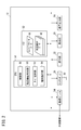
- FIG. 2 is an electrical block diagram of the pump device 12 shown in FIG.
- the pump device 12 includes a display unit 20, an operation unit 22, and an insulin pump 28 in FIG. 1, a central processing unit (hereinafter referred to as CPU 50), a memory 52, a communication module 54, and an audio output unit 56 (notification means). ).
- CPU 50 central processing unit
- memory 52 a memory 52
- communication module 54 a communication module 54
- audio output unit 56 notification means
- the communication module 54 transmits and receives various signals to and from an external device by wire or wireless.
- a radio frequency (RF) module for realizing wireless communication may be applied.
- RF radio frequency
- the sound output unit 56 outputs various sounds for informing the user.
- the voice output unit 56 outputs, for example, a warning sound including a buzzer and a beep, and a guidance message in each language.
- the memory 52 stores programs and data necessary for the CPU 50 to control each component.
- the memory 52 may be a non-transitory storage medium including a non-volatile memory and a hard disk.
- injection protocol data 66 and a plurality of discrimination condition data 68 are stored.
- the CPU 50 can implement the functions of the control unit 58, the hypoglycemia determination unit 60 (hypoglycemia determination unit), the mode switching unit 62, and the notification instruction unit 64 by reading and executing the program stored in the memory 52. It is.
- FIG. 3A is a schematic perspective view of the vital sensor 14, and FIG. 3B is a schematic block diagram showing a configuration of the vital sensor 14 of FIG. 3A.
- a multipurpose measuring instrument which is one form of the vital sensor 14 is illustrated.
- the vital sensor 14 fixed to a part of the band 70 is attached to the distal end portion (more specifically, the wrist 74) of the arm 72 of the injection target.
- the vital sensor 14 shown in FIG. 3B basically includes a CPU 80, a memory 81, a communication module 82, a pulse sensor 83, an activity sensor 84, an operation unit 85, and a display unit 86. Since the CPU 80, the memory 81, the communication module 82, the operation unit 85, and the display unit 86 can have the same configuration as that in FIG. 2, description of the configuration and function of each unit is omitted.
- the pulse sensor 83 is a sensor that can acquire a pulse rate as a biological signal by detecting a pulsation (pressure) appearing on the skin.
- the pulse sensor 83 is not limited to this method, and may employ various detection methods such as an optical sensor that detects a change in blood flow from the amount of reflected infrared light projected toward the skin (capillary blood vessel).
- the activity amount sensor 84 includes, for example, a triaxial acceleration sensor, and acquires the activity amount as a biological signal by converting the detected acceleration into a work amount.
- Examples of the amount of activity include energy consumption, METs (metabolic equivalents) values, exercise values, and the like.
- a display unit 86 as a notification unit is provided on one surface 76 of the vital sensor 14 that does not contact the injection target.
- the position of the other surface 78 of the vital sensor 14 is adjusted so as to come into pressure contact with a position close to the artery inside the wrist 74.
- FIG. 4 is a graph showing an example of a temporal change of vital signs in the injectable body.
- the horizontal axis of the graph represents time (time), and the vertical axis represents blood glucose level (unit: mg / dl) and pulse rate (unit: BPM) as vital signs.
- BPM pulse rate
- the pulse rate changes stably. Thereafter, when hypoglycemia develops and the blood glucose level falls below 70 [mg / dl], the parasympathetic nerve becomes active and bradycardia occurs, so the pulse rate temporarily decreases. Then, symptoms such as a feeling of hunger and lack of illness occur in the injected body, and symptoms such as headache, dizziness, and nausea occur when further progressed.
- step S1 the control unit 58 instructs the insulin pump 28 to inject insulin.
- the control unit 58 refers to the injection protocol data 66 read from the memory 52 and transmits a control signal indicating the amount of insulin injected. Thereby, as shown in FIG. 1, a predetermined injection amount of insulin is injected into the injected body through the tube 30 and the cannula 42.
- step S2 the control unit 58 acquires a biological signal from the vital sensor 14.
- the pulse sensor 83 and the activity amount sensor 84 acquire the pulse rate and the activity amount of the injected body, respectively, in accordance with a command from the CPU 80 in FIG. 3B.
- the communication module 82 sends out the pulse rate and activity as a biological signal.
- the CPU 50 of FIG. 2 temporarily stores the biological signal received via the communication module 54 in the memory 52.
- This acquisition process may be executed at a sampling interval preset in the vital sensor 14, or may be executed in response to a request (measurement instruction) from the pump device 12.
- the hypoglycemia determination unit 60 determines whether or not there is a sign of hypoglycemia in the injected body based on the biological signal acquired in step S2.
- the presence / absence of the signs is determined in a complex and multifaceted manner.
- the hypoglycemia determination unit 60 is low when the pulse rate is equal to or greater than a first threshold (for example, 75 [BPM]) and the amount of activity is equal to or less than the second threshold (for example, Ath). Determine if there is any sign of glycemia.
- FIG. 6 and 7 are graphs showing examples of changes in vital signs over time.
- FIG. 6 is a graph illustrating changes in pulse rate and amount of activity when the injected body starts exercising.
- FIG. 7 is a graph illustrating changes in the pulse rate and the amount of activity when the injected body develops hypoglycemia.
- the pulse rate is smaller than the first threshold when time t ⁇ T, but the pulse rate is larger than the first threshold when time t> T.
- the activity amount is larger than the second threshold value.
- the hypoglycemia determination unit 60 estimates that the pulse rate has increased due to exercise, and determines that there is no sign of hypoglycemia.
- the pulse rate is smaller than the first threshold when time t ⁇ T, but the pulse rate is larger than the first threshold when time t> T.
- the amount of activity is smaller than the second threshold value.
- the hypoglycemia determination unit 60 excludes the possibility that the pulse rate has increased due to exercise, and determines that there is a sign of hypoglycemia.
- the hypoglycemia determination unit 60 sequentially determines whether or not there is a sign of hypoglycemia in the injected body (step S4). If it is determined that there is no sign, the process returns to step S1 and steps S1 to S3 are sequentially repeated. On the other hand, when it is determined that there is an indication, the mode switching unit 62 notifies the control unit 58 that the “normal mode” is switched to the “hypoglycemia mode”.
- hypoglycemia mode Second, the operation of the pump device 12 in the hypoglycemia mode will be described in detail with reference to the flowchart of FIG. It should be noted that in the hypoglycemia mode, the pump device 12 performs a processing operation (hereinafter referred to as “emergency processing”) for performing an emergency treatment or measure for hypoglycemia.
- electronic processing a processing operation for performing an emergency treatment or measure for hypoglycemia.
- step S5 the control unit 58 instructs each unit of the pump device 12 to execute the emergency process.
- the injected body has lost consciousness as a result of the rapid progression of hypoglycemia.
- the control unit 58 may instruct the insulin pump 28 to reduce the amount of insulin injected compared to the normal mode.
- the controller 58 may instruct the insulin pump 28 to stop injecting insulin.
- the control unit 58 may instruct the audio output unit 56 to output various sounds for notifying the user that there is a sign of hypoglycemia.
- the control unit 58 may instruct the display unit 20 to display various images for notifying the user that there is a sign of hypoglycemia.
- the control unit 58 transmits an instruction signal to the vital sensor 14 mounted at a position where it can be easily seen, and notifies that there is a sign of hypoglycemia on behalf of the pump device 12. Also good.
- step S6 the control unit 58 starts monitoring the elapsed time from when the emergency process in step S5 is executed (that is, initializes the timer).
- step S ⁇ b> 7 the control unit 58 acquires a biological signal from the vital sensor 14. This acquisition process may be the same as or different from the case of step S2.
- step S8 the hypoglycemia determination unit 60 determines whether or not there is a sign of hypoglycemia in the injected body based on the biological signal acquired in step S7. In this determination processing, the same or different method as in step S3 may be used.
- step S9 the hypoglycemia determination unit 60 determines whether or not the injection target has recovered from the hypoglycemia.
- the hypoglycemia determination unit 60 may perform the determination after considering not only the current determination result but also the most recent determination result at least once. If it is determined that it has not been recovered, the process proceeds to the next step (S10).
- step S10 the control unit 58 determines whether or not a certain time has elapsed since the start of monitoring in step S6. If it is determined that the time has not elapsed, the process returns to step S7, and steps S7 to S9 are sequentially repeated. On the other hand, if it is determined that the time has elapsed, the process returns to step S5 (emergency process), and steps S5 to S10 are sequentially repeated.
- step S11 If it is determined in step S9 that the patient has recovered from hypoglycemia, in step S11, the control unit 58 ends the emergency process in step S5 and the time monitoring in step S6. Thereafter, the mode switching unit 62 notifies the control unit 58 of switching from the “hypoglycemia mode” to the “normal mode”.
- the blood glucose management system 10 is operated while switching between the “normal mode” and the “hypoglycemia mode” in a timely manner.
- the blood glucose management system 10 includes an insulin pump 28 that continuously injects insulin subcutaneously into an injected body, a pump device 12 that has a control unit 58 that controls an insulin injecting operation, and a vital sign of the injected body. And a hypoglycemia determination unit 60 for determining whether or not the injected body has a sign of hypoglycemia based on the acquired biological signal.
- hypoglycemia determining unit 60 determines whether there is a sign of hypoglycemia. If it is determined by the hypoglycemia determining unit 60 that there is a sign of hypoglycemia, an emergency treatment for hypoglycemia is performed from the “normal mode” in which insulin is injected in accordance with the instructed injection protocol data 66. Since the mode switching unit 62 for switching to the “hypoglycemia mode” for performing the measure is provided, it becomes possible to perform an emergency treatment or measure on the injected body in which signs of hypoglycemia are observed, Can be implemented.
- FIG. 9 is a schematic configuration diagram of a blood sugar management system 10A according to the first modification.
- the blood glucose management system 10 ⁇ / b> A further includes a data processing device 90 in addition to the pump device 12 ⁇ / b> A and the vital sensor 14.
- the pump device 12A is substantially the same as the configuration shown in FIGS. 1 and 2 except that the function of the hypoglycemia determination unit 60 (see FIG. 2) is missing.
- the data processing device 90 includes the hypoglycemia determination unit 60 and is configured to be able to communicate with the pump device 12A and the vital sensor 14.
- the data processing device 90 acquires a biological signal from the vital sensor 14 (see steps S2 and S7), performs a hypoglycemia discrimination process (see steps S3 and S8), and pumps the discrimination result. What is necessary is just to supply to the device 12A side. Thus, even if the hypoglycemia determination means is provided separately from the pump device 12A, the same effect as the present invention can be obtained.
- the vital sensor 14 may be composed of, for example, at least one of a pulse sensor, an activity sensor, a sweat sensor, an acceleration sensor, and a blood glucose sensor.
- the determination condition data 68 corresponding to the type (or combination) of the vital sensor 14 may be stored in the memory 52 and selectively read out as necessary.
- the vital sensor 14 may be a sweat sensor that acquires the amount of sweat as a biological signal.
- the hypoglycemia determination unit 60 determines that there is a sign of hypoglycemia when the amount of sweat is equal to or greater than the threshold. This is because when the blood glucose level falls below 50 [mg / dl], the sympathetic nerve becomes active, so that the symptom of sweating (especially cold sweat) is likely to occur.
- the body to be injected is equipped with a perspiration sensor at a site (palm or sole of the foot) where cold sweat is easily detected.
- the perspiration sensor for example, various methods including a ventilation capsule type (difference method and flow rate compensation method) can be adopted.
- the vital sensor 14 may be configured by an acceleration sensor that acquires a time series of acceleration as a biological signal.
- the hypoglycemia determination unit 60 determines that there is a sign of hypoglycemia when the main frequency in the time-series spectrum of acceleration is equal to or greater than the threshold value. This is because when the blood sugar level falls below 50 [mg / dl], the sympathetic nerves become active, so that the symptoms of trembling are likely to occur.
- the acceleration sensor various types including a piezoelectric type, a capacitance type, a servo type, and a bubble type can be adopted.
- the vital sensor 14 may be a blood glucose sensor that acquires a blood glucose level as a biological signal.
- the hypoglycemia determination unit 60 determines that there is a sign of hypoglycemia when the blood glucose level is equal to or higher than the threshold value.
- judgment criterion it is known that there are individual differences in this threshold value (judgment criterion). Therefore, the accuracy of the discrimination process is further improved by using other types of vital sensors together.
- a blood glucose sensor a sensor that optically measures glucose in blood and a sensor that measures blood glucose level electrically (electrochemical method) by an enzyme electrode method using an enzyme such as glucose oxidase (GOD) are applied. Also good.
Landscapes
- Health & Medical Sciences (AREA)
- Engineering & Computer Science (AREA)
- Life Sciences & Earth Sciences (AREA)
- Biomedical Technology (AREA)
- Public Health (AREA)
- General Health & Medical Sciences (AREA)
- Physics & Mathematics (AREA)
- Medical Informatics (AREA)
- Veterinary Medicine (AREA)
- Animal Behavior & Ethology (AREA)
- Heart & Thoracic Surgery (AREA)
- Epidemiology (AREA)
- Pathology (AREA)
- Molecular Biology (AREA)
- Biophysics (AREA)
- Surgery (AREA)
- Primary Health Care (AREA)
- Optics & Photonics (AREA)
- Bioinformatics & Cheminformatics (AREA)
- Vascular Medicine (AREA)
- Business, Economics & Management (AREA)
- Chemical & Material Sciences (AREA)
- Emergency Medicine (AREA)
- Medicinal Chemistry (AREA)
- Cardiology (AREA)
- General Business, Economics & Management (AREA)
- Physiology (AREA)
- Spectroscopy & Molecular Physics (AREA)
- Diabetes (AREA)
- Anesthesiology (AREA)
- Hematology (AREA)
- Infusion, Injection, And Reservoir Apparatuses (AREA)
Description
この発明は、被注入体に対してインスリンを持続的に皮下注入するための血糖管理システム及び血糖管理方法に関する。
近時、糖尿病の患者(被注入体)の体内にインスリンを注入するためのインスリンポンプが開発されている。このポンプを用いることで、注射を行うことなくインスリンが患者の体内に持続的・間欠的に供給されるので、血糖値の調整を簡便に行うことができる。そして、患者の負担を更に軽減しつつ、適確な血糖管理を実現するための技術が種々提案されている。
特開2004-024699号公報では、患者から測定された血糖値データを、移動通信ネットワークに接続された管理サーバ側に供給し、この管理サーバを用いてインスリンの注入量を決定し、この患者が装着する注入装置にその注入量を反映させるシステム及び方法が提案されている。
ところで、低血糖症を起こした後にその症状が急速に進行する場合、患者は、意識消失等の重篤な症状を起こすことがある。このとき、患者は周囲に対して救急を要請できないが、この患者に対して何らの処置・措置を施す必要があった。
しかしながら、特開2004-024699号公報に記載のシステム等は、そもそも日常の血糖管理を目的としたものであり、このような緊急事態について何ら考慮されていない。
本発明は上記した問題を解決するためになされたもので、被注入体に対して効果的な処置等を実行可能な血糖管理システム及び血糖管理方法を提供することを目的とする。
本発明に係る血糖管理システムは、被注入体に対してインスリンを持続的に皮下注入するポンプと、前記ポンプによる前記インスリンの注入動作を制御する制御部とを有するポンプデバイスと、前記被注入体のバイタルサインを示す生体信号を取得するバイタルセンサと、前記バイタルセンサから取得された前記生体信号に基づいて前記被注入体に低血糖症の兆候があるか否かを判別する低血糖症判別手段とを備え、前記ポンプデバイスは、前記低血糖症判別手段により前記低血糖症の兆候があると判別された場合に、指示された注入プロトコールに従って前記インスリンを注入する通常モードから、前記低血糖症に対する応急的な処置又は措置を行う低血糖症モードに切り替えるモード切替部を更に有することを特徴とする。
このように、低血糖症判別手段により低血糖症の兆候があると判別された場合に、指示された注入プロトコールに従ってインスリンを注入する通常モードから、低血糖症に対する応急的な処置又は措置を行う低血糖症モードに切り替えるモード切替部を設けたので、低血糖症の兆候がみられた被注入体に対して応急的な処置又は措置を行うことが可能になり、効果的な処置等を実行できる。
また、前記制御部は、前記モード切替部により前記低血糖症モードに切り替えられた場合、前記インスリンの注入を減量又は停止させるように、前記ポンプを制御することが好ましい。これにより、インスリンの過剰供給によって被注入体の症状が却って悪化するリスクを考慮した処置を採ることができる。
また、前記ポンプデバイスは、ユーザに報知する報知手段を更に有し、前記制御部は、前記モード切替部により前記低血糖症モードに切り替えられた場合、前記低血糖症の兆候がある旨を報知するように前記報知手段を制御することが好ましい。これにより、意識喪失等で身動きが取れない被注入体に代わって、この被注入体の存在を他人に知らせるための一助となる措置を採ることができる。
更に、前記バイタルセンサは、脈拍センサ、活動量センサ、発汗センサ、加速度センサ及び血糖センサのうちの少なくとも1つで構成されることが好ましい。
更に、前記バイタルセンサは、前記生体信号としての脈拍数を取得する脈拍センサ、及び前記生体信号としての活動量を取得する活動量センサで構成され、前記低血糖症判別手段は、前記脈拍数が第1閾値以上であり且つ前記活動量が第2閾値以下である場合に前記低血糖症の兆候があると判別することが好ましい。
或いは、前記バイタルセンサは、前記生体信号としての発汗量を取得する発汗センサで構成され、前記低血糖症判別手段は、前記発汗量が閾値以上である場合に前記低血糖症の兆候があると判別することが好ましい。
或いは、前記バイタルセンサは、前記生体信号としての加速度の時系列を取得する加速度センサで構成され、前記低血糖症判別手段は、前記加速度の時系列のスペクトルにおける主周波数が閾値以上である場合に前記低血糖症の兆候があると判別することが好ましい。
或いは、前記バイタルセンサは、前記生体信号としての血糖値を取得する血糖センサで構成され、前記低血糖症判別手段は、前記血糖値が閾値以上である場合に前記低血糖症の兆候があると判別することが好ましい。
本発明に係る血糖管理方法は、被注入体に対してインスリンを持続的に皮下注入するポンプを有するポンプデバイスを用いた方法であって、バイタルセンサを用いて、前記被注入体のバイタルサインを示す生体信号を取得する取得ステップと、取得された前記生体信号に基づいて前記被注入体に低血糖症の兆候があるか否かを判別する判別ステップと、前記低血糖症の兆候があると判別された場合に、指示された注入プロトコールに従って前記ポンプを介して前記インスリンを注入する通常モードから、前記低血糖症に対する応急的な処置又は措置を行う低血糖症モードに切り替える切替ステップとを備えることを特徴とする。
本発明に係る血糖管理システム及び血糖管理方法によれば、低血糖症の兆候があると判別された場合に、指示された注入プロトコールに従ってインスリンを注入する通常モードから、低血糖症に対する応急的な処置又は措置を行う低血糖症モードに切り替えるので、低血糖症の兆候がみられた被注入体に対して応急的な処置又は措置を行うことが可能になり、効果的な処置等を実行できる。
以下、本発明に係る血糖管理方法について、血糖管理システムとの関係において好適な実施形態を挙げ、添付の図面を参照しながら説明する。
[血糖管理システム10の構成]
<全体構成>
図1は、この実施形態に係る血糖管理システム10の概略斜視図である。
<全体構成>
図1は、この実施形態に係る血糖管理システム10の概略斜視図である。
血糖管理システム10は、基本的には、糖尿病の患者を含む被注入体に対してインスリンを持続的に皮下注入するためのポンプデバイス12と、被注入体のバイタルサインを示す生体信号を取得するバイタルセンサ14とから構成される。
ポンプデバイス12は、概略矩形状の筐体16を有する。その主面18には、ポンプデバイス12の動作状態を可視化した各種画像を表示する表示部20(報知手段)、及び複数の押圧式ボタンからなる操作部22が配置されている。
筐体16の側面24の短辺側辺縁部が切り欠かれており、これにより挿入口26が形成されている。この挿入口26を介して、概略円筒状のインスリンポンプ28(ポンプ)を筐体16内に収容可能であると共に、筐体16から取り外し可能である。インスリンポンプ28の先端部に、インスリンを移送するためのチューブ30の一端32が接続されている。チューブ30の他端34には嵌合部36が設けられており、注入セット38の一部(後述する被嵌合部44)と嵌合可能である。
注入セット38は、円盤状の固定シート40と、固定シート40の一面41側略中央に配されたカニューレ42と、固定シート40の他面43に配された被嵌合部44とから構成される。固定シート40の一面41には接着層が設けられている。被嵌合部44の上面側には開口部46が設けられており、この開口部46を介してカニューレ42の内部に連通する。
以下、インスリンの注入動作について説明する。先ず、被注入体の体表にカニューレ42を穿刺した後に、固定シート40の一面41(粘着層)を皮膚に接触させることで、注入セット38が皮膚に固定される。これにより、カニューレ42を皮下に留置可能である。そして、チューブ30の嵌合部36を注入セット38の被嵌合部44に嵌合させることで、インスリンポンプ28の内部は、チューブ30、被嵌合部44及びカニューレ42を介して外部48に連通する。すなわち、インスリンポンプ28から押し出されたインスリンは、チューブ30、被嵌合部44及びカニューレ42を通じて外部48に移送され、その結果、被注入体の内部に注入される。この移送動作を遂次繰り返すことで、被注入体に対してインスリンを持続的又は間欠的に皮下注入できる。
図2は、図1に示すポンプデバイス12の電気的なブロック図である。
ポンプデバイス12は、図1の表示部20、操作部22、及びインスリンポンプ28の他、中央演算処理装置(以下、CPU50)と、メモリ52と、通信モジュール54と、音声出力部56(報知手段)とを更に備える。
通信モジュール54は、有線又は無線により、外部装置との間で各種信号の送受信を行う。通信モジュール54として、例えば、無線通信を実現するためのRF(Radio Frequency)モジュールを適用してもよい。特に、ポンプデバイス12及びバイタルセンサ14は同一の被注入体に装着されるので、近距離通信用の規格(例えば、「IEEE 802.15.6」で規定するボディエリアネットワーク等)を適用してもよい。
音声出力部56は、ユーザに報知するための各種音声を出力する。音声出力部56は、例えば、ブザー、ビープ等を含む警告音や、各国の言語によるガイダンス・メッセージを出力する。
メモリ52は、CPU50が各構成要素を制御するのに必要なプログラム及びデータ等を記憶している。メモリ52は、不揮発性のメモリ、ハードディスク等を含む非一過性の記憶媒体であればよい。本図例では、注入プロトコールデータ66、及び複数の判別条件データ68がそれぞれ格納されている。
CPU50は、メモリ52に格納されたプログラムを読み出し実行することで、制御部58、低血糖症判別部60(低血糖症判別手段)、モード切替部62、及び報知指示部64の機能を実現可能である。
<バイタルセンサ14の構成>
図3Aはバイタルセンサ14の概略斜視図であり、図3Bは図3Aのバイタルセンサ14の構成を示す概略ブロック図である。本図例では、バイタルセンサ14の一形態である多目的計測器を図示している。
図3Aはバイタルセンサ14の概略斜視図であり、図3Bは図3Aのバイタルセンサ14の構成を示す概略ブロック図である。本図例では、バイタルセンサ14の一形態である多目的計測器を図示している。
図3Aに示すように、バンド70の一部に固定されたバイタルセンサ14が、被注入体の腕72の先端部(より詳細には手首74)に装着されている。
図3Bに示すバイタルセンサ14は、CPU80、メモリ81、通信モジュール82、脈拍センサ83、活動量センサ84、操作部85、及び表示部86を基本的に備える。CPU80、メモリ81、通信モジュール82、操作部85、及び表示部86に関しては図2と同様の構成を採り得るので、各部の構成及び機能の説明を省略する。
脈拍センサ83は、皮膚に現われる脈動(圧力)を検出することで、生体信号としての脈拍数を取得可能なセンサである。脈拍センサ83は、この方式に限られず、皮膚(毛細血管)に向けて投光された赤外線の反射光量から血流の変化を検出する光学式センサ等、種々の検出方式を採ってもよい。
活動量センサ84は、例えば3軸加速度センサを備えており、検出された加速度を仕事量に換算することで、生体信号としての活動量を取得する。活動量として、例えば、エネルギー消費量、METs(metabolic equivalents)値、エクササイズ値等が挙げられる。
図3Aに戻って、被注入体に接触しないバイタルセンサ14の一面76には、報知手段としての表示部86が設けられている。一方、バイタルセンサ14の他面78は、手首74の内側の動脈に近接した位置に圧接するように位置が調整されている。
<低血糖症と各種生体信号との関係>
図4は、被注入体内におけるバイタルサインの経時的変化の一例を示すグラフである。グラフの横軸は時間(時刻)を表しており、縦軸はバイタルサインとしての血糖値(単位:mg/dl)及び脈拍数(単位:BPM)を表す。本図例では、正常状態であった被注入体が、突然、低血糖症を起こした場合の変化を示している。
図4は、被注入体内におけるバイタルサインの経時的変化の一例を示すグラフである。グラフの横軸は時間(時刻)を表しており、縦軸はバイタルサインとしての血糖値(単位:mg/dl)及び脈拍数(単位:BPM)を表す。本図例では、正常状態であった被注入体が、突然、低血糖症を起こした場合の変化を示している。
血糖値が70[mg/dl]以上である場合、脈拍数は安定的に推移する。その後、低血糖症を発症し、血糖値が70[mg/dl]を下回った場合、副交感神経が活発になり徐脈が発生するので、脈拍数が一時的に低下する。すると、被注入体には、空腹感や欠伸等の症状が起こると共に、更に進行すると、頭痛、眩暈、吐き気等の症状が起こる。
その後、血糖値が50[mg/dl]を下回った場合、生命の維持のため、血糖を上昇させるアドレナリン等のホルモンが多く分泌されるようになる。これにより、刺激された交感神経が活発になり頻脈が発生するので、脈拍数が急激に上昇する。この際、発汗、動悸又は震え等の症状が起こる。このように、被注入体の各種バイタルサインの経時的変化は、低血糖症を発症したか否かについての1つの判断材料になり得る。
[血糖管理システム10の動作]
続いて、血糖管理システム10の動作について、図5及び図8のフローチャート及び必要な図面を参照しながら説明する。この実施形態では、ポンプデバイス12に関する2種類の動作モード、具体的には、「通常モード」及び「低血糖症モード」をそれぞれ用意し、モードの切り替えを適時行う。なお、低血糖症の兆候(傾向)がない場合でのポンプデバイス12の動作モードを「通常モード」という。また、低血糖症の兆候がある場合でのポンプデバイス12の動作モードを「低血糖症モード」という。
続いて、血糖管理システム10の動作について、図5及び図8のフローチャート及び必要な図面を参照しながら説明する。この実施形態では、ポンプデバイス12に関する2種類の動作モード、具体的には、「通常モード」及び「低血糖症モード」をそれぞれ用意し、モードの切り替えを適時行う。なお、低血糖症の兆候(傾向)がない場合でのポンプデバイス12の動作モードを「通常モード」という。また、低血糖症の兆候がある場合でのポンプデバイス12の動作モードを「低血糖症モード」という。
<通常モードの動作説明>
第1に、通常モードにおけるポンプデバイス12の動作について、図5のフローチャートを参照しながら詳細に説明する。通常モードにおいて、ポンプデバイス12は、指示された注入プロトコール(初回注入量、注入速度、総注入量等)に従ってインスリンを注入する動作を実行する点に留意する。
第1に、通常モードにおけるポンプデバイス12の動作について、図5のフローチャートを参照しながら詳細に説明する。通常モードにおいて、ポンプデバイス12は、指示された注入プロトコール(初回注入量、注入速度、総注入量等)に従ってインスリンを注入する動作を実行する点に留意する。
ステップS1において、制御部58は、インスリンポンプ28に対して、インスリンの注入を指示する。具体的には、制御部58は、メモリ52から読み出した注入プロトコールデータ66を参照し、インスリンの注入量を示す制御信号を送信する。これにより、図1に示す通り、予め設定された注入量のインスリンが、チューブ30及びカニューレ42を介して、被注入体の内部に注入される。
ステップS2において、制御部58は、バイタルセンサ14からの生体信号を取得する。取得に先立ち、図3BのCPU80からの指令に応じて、脈拍センサ83及び活動量センサ84は、被注入体の脈拍数及び活動量をそれぞれ取得する。その後、通信モジュール82は、生体信号としての脈拍数及び活動量を外部に送出する。その後、図2のCPU50は、通信モジュール54を介して受信した生体信号を、メモリ52に一時的に記憶させておく。なお、この取得処理は、バイタルセンサ14に予め設定されたサンプリング間隔で実行してもよいし、ポンプデバイス12からの要求(計測指示)に応じて実行してもよい。
ステップS3において、低血糖症判別部60は、ステップS2で取得された生体信号に基づいて、被注入体に低血糖症の兆候があるか否かを判別する。ここでは、バイタルサインとしての脈拍数及び活動量を用いて、その兆候の有無について複合的・多角的に判別する。具体的には、低血糖症判別部60は、脈拍数が第1閾値(例えば、75[BPM])以上であり、且つ、活動量が第2閾値(例えば、Ath)以下である場合に低血糖症の兆候があると判別する。
図6及び図7は、バイタルサインの経時的変化の各例を示すグラフである。図6は、被注入体が運動を開始した場合における脈拍数及び活動量の変化を例示するグラフである。図7は、被注入体が低血糖症を発症した場合における脈拍数及び活動量の変化を例示するグラフである。
図6において、時間t<Tの場合に脈拍数が第1閾値よりも小さいが、時間t>Tの場合に脈拍数が第1閾値よりも大きくなる。その一方、時間t>Tの場合では、活動量が第2閾値よりも大きくなっている。この場合、低血糖症判別部60は、運動により脈拍数が高くなったものと推定し、低血糖症の兆候がないと判別する。
図7において、時間t<Tの場合に脈拍数が第1閾値よりも小さいが、時間t>Tの場合に脈拍数が第1閾値よりも大きくなる。そして、時間t>Tの場合では、活動量が第2閾値よりも小さくなっている。この場合、低血糖症判別部60は、運動により脈拍数が高くなった可能性を排除し、低血糖症の兆候があると判別する。
このようにして、低血糖症判別部60は、被注入体に低血糖症の兆候があるか否かを遂次判別する(ステップS4)。兆候がないと判別された場合、ステップS1に戻って、以下ステップS1~S3を順次繰り返す。一方、兆候があると判別された場合、モード切替部62は、「通常モード」から「低血糖症モード」に切り替える旨を制御部58に通知する。
<低血糖症モードの動作説明>
第2に、低血糖症モードにおけるポンプデバイス12の動作について、図8のフローチャートを参照しながら詳細に説明する。低血糖症モードにおいて、ポンプデバイス12は、低血糖症に対する応急的な処置又は措置を行う処理動作(以下、「応急処理」という)を実行する点に留意する。
第2に、低血糖症モードにおけるポンプデバイス12の動作について、図8のフローチャートを参照しながら詳細に説明する。低血糖症モードにおいて、ポンプデバイス12は、低血糖症に対する応急的な処置又は措置を行う処理動作(以下、「応急処理」という)を実行する点に留意する。
ステップS5において、制御部58は、ポンプデバイス12の各部に対して、応急処理を実行する旨を指示する。ここでは、低血糖症の急速な進行の結果、被注入体が意識消失を起こした場合を想定する。
処置動作の第1形態として、制御部58は、インスリンポンプ28に対して、通常モードよりもインスリンの注入を減量する旨を指示してもよい。処置動作の第2形態として、制御部58は、インスリンポンプ28に対して、インスリンの注入を停止する旨を指示してもよい。これらは、インスリンの過剰供給によって被注入体の症状が却って悪化するリスクを考慮した処置である。
措置動作の第1形態として、制御部58は、音声出力部56に対して、低血糖症の兆候がある旨をユーザに報知するための各種音声を出力する旨を指示してもよい。措置動作の第2形態として、制御部58は、表示部20に対して、低血糖症の兆候がある旨をユーザに報知するための各種画像を表示する旨を指示してもよい。措置動作の第3形態として、制御部58は、視認され易い位置に装着されたバイタルセンサ14側に指示信号を送信し、ポンプデバイス12に代わって低血糖症の兆候がある旨を報知させてもよい。これらは、意識喪失等で身動きが取れない被注入体に代わって、この被注入体の存在を他人に知らせるための一助となる措置である。特に、緊急事態を想起させる報知を行うことで、他人により、被注入体が睡眠中であると誤認されることを防止できる。
ステップS6において、制御部58は、ステップS5による応急処理を実行した時点からの経過時間の監視を開始(すなわち、タイマを初期化)する。
ステップS7において、制御部58は、バイタルセンサ14からの生体信号を取得する。この取得処理は、ステップS2の場合と同一の形態であっても異なる形態であってもよい。
ステップS8において、低血糖症判別部60は、ステップS7で取得された生体信号に基づいて、被注入体に低血糖症の兆候があるか否かを判別する。この判別処理では、ステップS3の場合と同一の又は異なる手法を用いてもよい。
ステップS9において、低血糖症判別部60は、被注入体が低血糖症から回復したか否かを判別する。低血糖症判別部60は、今回の判別結果のみならず、直近の少なくとも1回の判別結果を併せて考慮した上で判別を行ってもよい。まだ回復していないと判別された場合、次のステップ(S10)に進む。
ステップS10において、制御部58は、ステップS6で監視を開始してから一定時間が経過したか否かを判別する。経過していないと判別された場合、ステップS7に戻って、以下ステップS7~S9を順次繰り返す。一方、経過したと判別された場合、ステップS5(応急処理)に戻って、ステップS5~S10を順次繰り返す。
ステップS9で低血糖症から回復したと判別された場合、ステップS11において、制御部58は、ステップS5での応急処理、及びステップS6での時間監視をそれぞれ終了する。その後、モード切替部62は、「低血糖症モード」から「通常モード」に切り替える旨を制御部58に通知する。
以上のようにして、「通常モード」及び「低血糖症モード」の切り替えを適時行いながら、血糖管理システム10を動作させる。
[本発明の効果]
この血糖管理システム10は、被注入体に対してインスリンを持続的に皮下注入するインスリンポンプ28と、インスリンの注入動作を制御する制御部58とを有するポンプデバイス12と、被注入体のバイタルサインを示す生体信号を取得するバイタルセンサ14と、取得された生体信号に基づいて被注入体に低血糖症の兆候があるか否かを判別する低血糖症判別部60とを備える。
この血糖管理システム10は、被注入体に対してインスリンを持続的に皮下注入するインスリンポンプ28と、インスリンの注入動作を制御する制御部58とを有するポンプデバイス12と、被注入体のバイタルサインを示す生体信号を取得するバイタルセンサ14と、取得された生体信号に基づいて被注入体に低血糖症の兆候があるか否かを判別する低血糖症判別部60とを備える。
そして、低血糖症判別部60により低血糖症の兆候があると判別された場合に、指示された注入プロトコールデータ66に従ってインスリンを注入する「通常モード」から、低血糖症に対する応急的な処置又は措置を行う「低血糖症モード」に切り替えるモード切替部62を設けたので、低血糖症の兆候がみられた被注入体に対して応急的な処置又は措置を行うことが可能になり、効果的な処置等を実行できる。
[第1変形例]
図9は、第1変形例に係る血糖管理システム10Aの概略構成図である。
図9は、第1変形例に係る血糖管理システム10Aの概略構成図である。
血糖管理システム10Aは、ポンプデバイス12A及びバイタルセンサ14の他に、データ処理装置90を更に備える。ここで、ポンプデバイス12Aは、図1及び図2に示す構成と略同じであるが、低血糖症判別部60(図2参照)の機能が欠落している点のみが異なる。そして、データ処理装置90は、低血糖症判別部60を有すると共に、ポンプデバイス12A及びバイタルセンサ14との間で通信可能に構成されている。
この構成を採る場合であっても、図5及び図8に示すフローチャートを実行可能である。例えば、データ処理装置90は、バイタルセンサ14からの生体信号を取得し(ステップS2、S7参照)、低血糖症の判別処理を行った上で(ステップS3、S8参照)、その判別結果をポンプデバイス12A側に供給すればよい。このように、ポンプデバイス12Aとは別に低血糖症判別手段を設けても、本発明と同様の作用効果を得ることができる。
[第2変形例]
バイタルセンサ14は、例えば、脈拍センサ、活動量センサ、発汗センサ、加速度センサ及び血糖センサのうちの少なくとも1つで構成されてもよい。この場合、バイタルセンサ14の種類(又は組み合わせ)に応じた判別条件データ68をそれぞれメモリ52に記憶しておき、必要に応じて選択的に読み出すようにしてもよい。
バイタルセンサ14は、例えば、脈拍センサ、活動量センサ、発汗センサ、加速度センサ及び血糖センサのうちの少なくとも1つで構成されてもよい。この場合、バイタルセンサ14の種類(又は組み合わせ)に応じた判別条件データ68をそれぞれメモリ52に記憶しておき、必要に応じて選択的に読み出すようにしてもよい。
<発汗センサ>
バイタルセンサ14は、生体信号としての発汗量を取得する発汗センサで構成されてもよい。この場合、低血糖症判別部60は、発汗量が閾値以上である場合に低血糖症の兆候があると判別する。これは、血糖値が50[mg/dl]を下回った場合、交感神経が活発になるので、発汗(特に冷や汗)の症状が起こり易いためである。被注入体は、冷や汗を検出し易い部位(手の平又は足の裏)に発汗センサを装着することが望ましい。発汗センサとして、例えば、換気カプセル型(差分方式や流量補償方式)を含む種々の方式を採り得る。
バイタルセンサ14は、生体信号としての発汗量を取得する発汗センサで構成されてもよい。この場合、低血糖症判別部60は、発汗量が閾値以上である場合に低血糖症の兆候があると判別する。これは、血糖値が50[mg/dl]を下回った場合、交感神経が活発になるので、発汗(特に冷や汗)の症状が起こり易いためである。被注入体は、冷や汗を検出し易い部位(手の平又は足の裏)に発汗センサを装着することが望ましい。発汗センサとして、例えば、換気カプセル型(差分方式や流量補償方式)を含む種々の方式を採り得る。
<加速度センサ>
バイタルセンサ14は、生体信号としての加速度の時系列を取得する加速度センサで構成されてもよい。この場合、低血糖症判別部60は、加速度の時系列のスペクトルにおける主周波数が閾値以上である場合に低血糖症の兆候があると判別する。これは、血糖値が50[mg/dl]を下回った場合、交感神経が活発になるので、小刻みな震えの症状が起こり易いためである。加速度センサとして、圧電式、静電容量式、サーボ式、気泡式を含む種々の方式を採り得る。
バイタルセンサ14は、生体信号としての加速度の時系列を取得する加速度センサで構成されてもよい。この場合、低血糖症判別部60は、加速度の時系列のスペクトルにおける主周波数が閾値以上である場合に低血糖症の兆候があると判別する。これは、血糖値が50[mg/dl]を下回った場合、交感神経が活発になるので、小刻みな震えの症状が起こり易いためである。加速度センサとして、圧電式、静電容量式、サーボ式、気泡式を含む種々の方式を採り得る。
<血糖センサ>
バイタルセンサ14は、生体信号としての血糖値を取得する血糖センサで構成されてもよい。この場合、低血糖症判別部60は、血糖値が閾値以上である場合に低血糖症の兆候があると判別する。血糖値の変化を直接的に監視する点では最も好ましいが、この閾値(判断基準)には個体差があることが知られている。そこで、他の種類のバイタルセンサを併せて用いることで、判別処理の確度が一層向上する。血糖センサとして、血中のグルコースを光学的に測定するセンサ、血糖値をグルコースオキシダーゼ(GOD)等の酵素を用いた酵素電極法等による電気的(電気化学方式)に測定するセンサを適用してもよい。
バイタルセンサ14は、生体信号としての血糖値を取得する血糖センサで構成されてもよい。この場合、低血糖症判別部60は、血糖値が閾値以上である場合に低血糖症の兆候があると判別する。血糖値の変化を直接的に監視する点では最も好ましいが、この閾値(判断基準)には個体差があることが知られている。そこで、他の種類のバイタルセンサを併せて用いることで、判別処理の確度が一層向上する。血糖センサとして、血中のグルコースを光学的に測定するセンサ、血糖値をグルコースオキシダーゼ(GOD)等の酵素を用いた酵素電極法等による電気的(電気化学方式)に測定するセンサを適用してもよい。
なお、この発明は、上述した実施形態に限定されるものではなく、この発明の主旨を逸脱しない範囲で自由に変更できることは勿論である。
Claims (8)
- 被注入体に対してインスリンを持続的に皮下注入するポンプ(28)と、前記ポンプ(28)による前記インスリンの注入動作を制御する制御部(58)とを有するポンプデバイス(12、12A)と、
前記被注入体のバイタルサインを示す生体信号を取得するバイタルセンサ(14)と、
前記バイタルセンサ(14)から取得された前記生体信号に基づいて前記被注入体に低血糖症の兆候があるか否かを判別する低血糖症判別手段(60)と
を備え、
前記ポンプデバイス(12、12A)は、
前記低血糖症判別手段(60)により前記低血糖症の兆候があると判別された場合に、指示された注入プロトコール(66)に従って前記インスリンを注入する通常モードから、前記低血糖症に対する応急的な処置又は措置を行う低血糖症モードに切り替えるモード切替部(62)を更に有する
ことを特徴とする血糖管理システム(10、10A)。 - 請求項1記載のシステム(10、10A)において、
前記制御部(58)は、前記モード切替部(62)により前記低血糖症モードに切り替えられた場合、前記インスリンの注入を減量又は停止させるように、前記ポンプ(28)を制御することを特徴とする血糖管理システム(10、10A)。 - 請求項1記載のシステム(10、10A)において、
前記ポンプデバイス(12、12A)は、ユーザに報知する報知手段(20、56)を更に有し、
前記制御部(58)は、前記モード切替部(62)により前記低血糖症モードに切り替えられた場合、前記低血糖症の兆候がある旨を報知するように前記報知手段(20、56)を制御することを特徴とする血糖管理システム(10、10A)。 - 請求項1~3のいずれか1項に記載のシステム(10、10A)において、
前記バイタルセンサ(14)は、脈拍センサ、活動量センサ、発汗センサ、加速度センサ及び血糖センサのうちの少なくとも1つで構成されることを特徴とする血糖管理システム(10、10A)。 - 請求項4記載のシステム(10、10A)において、
前記バイタルセンサ(14)は、前記生体信号としての脈拍数を取得する脈拍センサ、及び前記生体信号としての活動量を取得する活動量センサで構成され、
前記低血糖症判別手段(60)は、前記脈拍数が第1閾値以上であり且つ前記活動量が第2閾値以下である場合に前記低血糖症の兆候があると判別する
ことを特徴とする血糖管理システム(10、10A)。 - 請求項4記載のシステム(10、10A)において、
前記バイタルセンサ(14)は、前記生体信号としての発汗量を取得する発汗センサで構成され、
前記低血糖症判別手段(60)は、前記発汗量が閾値以上である場合に前記低血糖症の兆候があると判別する
ことを特徴とする血糖管理システム(10、10A)。 - 請求項4記載のシステム(10、10A)において、
前記バイタルセンサ(14)は、前記生体信号としての加速度の時系列を取得する加速度センサで構成され、
前記低血糖症判別手段(60)は、前記加速度の時系列のスペクトルにおける主周波数が閾値以上である場合に前記低血糖症の兆候があると判別する
ことを特徴とする血糖管理システム(10、10A)。 - 請求項4記載のシステム(10、10A)において、
前記バイタルセンサ(14)は、前記生体信号としての血糖値を取得する血糖センサで構成され、
前記低血糖症判別手段(60)は、前記血糖値が閾値以上である場合に前記低血糖症の兆候があると判別する
ことを特徴とする血糖管理システム(10、10A)。
Priority Applications (1)
| Application Number | Priority Date | Filing Date | Title |
|---|---|---|---|
| PCT/JP2012/074328 WO2014045425A1 (ja) | 2012-09-24 | 2012-09-24 | 血糖管理システム |
Applications Claiming Priority (1)
| Application Number | Priority Date | Filing Date | Title |
|---|---|---|---|
| PCT/JP2012/074328 WO2014045425A1 (ja) | 2012-09-24 | 2012-09-24 | 血糖管理システム |
Publications (1)
| Publication Number | Publication Date |
|---|---|
| WO2014045425A1 true WO2014045425A1 (ja) | 2014-03-27 |
Family
ID=50340775
Family Applications (1)
| Application Number | Title | Priority Date | Filing Date |
|---|---|---|---|
| PCT/JP2012/074328 Ceased WO2014045425A1 (ja) | 2012-09-24 | 2012-09-24 | 血糖管理システム |
Country Status (1)
| Country | Link |
|---|---|
| WO (1) | WO2014045425A1 (ja) |
Cited By (1)
| Publication number | Priority date | Publication date | Assignee | Title |
|---|---|---|---|---|
| EP3902462A4 (en) * | 2019-03-19 | 2022-03-02 | Samsung Electronics Co., Ltd. | ELECTRONIC DEVICE AND METHOD FOR COMMUNICATION OF BIOMETRIC INFORMATION THROUGH AN ELECTRONIC DEVICE |
Citations (4)
| Publication number | Priority date | Publication date | Assignee | Title |
|---|---|---|---|---|
| JPS61259645A (ja) * | 1985-05-14 | 1986-11-17 | シチズン時計株式会社 | 低血糖検出装置 |
| JP2008229331A (ja) * | 2007-03-20 | 2008-10-02 | Lifescan Inc | 血糖症管理用の伝達媒体 |
| JP2008253560A (ja) * | 2007-04-05 | 2008-10-23 | Shinichi Yoshida | 擬似低血糖検知・警報発信装置 |
| JP2011200628A (ja) * | 2010-10-19 | 2011-10-13 | Seiko Epson Corp | 流体注入システム |
-
2012
- 2012-09-24 WO PCT/JP2012/074328 patent/WO2014045425A1/ja not_active Ceased
Patent Citations (4)
| Publication number | Priority date | Publication date | Assignee | Title |
|---|---|---|---|---|
| JPS61259645A (ja) * | 1985-05-14 | 1986-11-17 | シチズン時計株式会社 | 低血糖検出装置 |
| JP2008229331A (ja) * | 2007-03-20 | 2008-10-02 | Lifescan Inc | 血糖症管理用の伝達媒体 |
| JP2008253560A (ja) * | 2007-04-05 | 2008-10-23 | Shinichi Yoshida | 擬似低血糖検知・警報発信装置 |
| JP2011200628A (ja) * | 2010-10-19 | 2011-10-13 | Seiko Epson Corp | 流体注入システム |
Cited By (1)
| Publication number | Priority date | Publication date | Assignee | Title |
|---|---|---|---|---|
| EP3902462A4 (en) * | 2019-03-19 | 2022-03-02 | Samsung Electronics Co., Ltd. | ELECTRONIC DEVICE AND METHOD FOR COMMUNICATION OF BIOMETRIC INFORMATION THROUGH AN ELECTRONIC DEVICE |
Similar Documents
| Publication | Publication Date | Title |
|---|---|---|
| US12048530B2 (en) | Method and apparatus for detecting false hypoglycemic conditions | |
| US20190196411A1 (en) | Smartwatch assemblies having electrocardiogram sensors, photoplethysmography sensors, and blood pressure monitors and related methods | |
| US9668686B2 (en) | In vivo glucose sensing in an increased perfusion dermal layer | |
| CN102006821A (zh) | 用于模块化分析物监测的设备、系统和方法 | |
| KR20160075230A (ko) | 비 침습적 혈당 측정 방법 및 이를 위한 장치 | |
| KR20170038351A (ko) | 유연 탐침 센서를 구비하는 연속혈당감시시스템 | |
| US20170095216A1 (en) | Biowatch | |
| US20240075271A1 (en) | Wireless Communication and Power Conservation for Implantable Monitors | |
| CA2882662A1 (en) | Methods and apparatuses for providing adverse condition notification in analyte monitoring systems | |
| JP5348707B2 (ja) | モジュールの検体モニタのための装置、システム及び方法 | |
| US12622622B2 (en) | Blood glucose states based on sensed brain activity | |
| CN105326481A (zh) | 一种无创伤动态血糖浓度预警系统 | |
| US20230218229A1 (en) | Monitoring patch | |
| KR20220024506A (ko) | 피분석물 선택적 센서 및 주입 시스템의 기계적 커플링 | |
| EP3459444B1 (en) | Biological information measurement support device, biological information measurement support method, and biological information measurement support program | |
| JP2018000310A (ja) | バイオセンサ、血糖値のアラート通知方法、および血糖値の測定装置 | |
| JP2025533670A (ja) | 低侵襲グルコース状態システム、デバイス、および方法 | |
| EP4183329B1 (en) | Method, system, wearable device, and medium for measuring a physiological signal | |
| US20260130625A1 (en) | Minimally invasive glucose state systems, devices, and methods | |
| KR102481493B1 (ko) | 전자 장치, 그 제어 방법 및 컴퓨터 판독가능 기록 매체 | |
| WO2026080527A1 (en) | Health information based on wearable sensors | |
| US20190117154A1 (en) | Measuring Apparatus, Computer Readable Medium Storing Measuring Program and Measuring Method | |
| JP2020110485A (ja) | 薬液投与装置 | |
| JP2010042102A (ja) | 生体情報モニタ、生体情報モニタにおける機能切替方法、および生体情報モニタにおける表示方法 |
Legal Events
| Date | Code | Title | Description |
|---|---|---|---|
| 121 | Ep: the epo has been informed by wipo that ep was designated in this application |
Ref document number: 12885173 Country of ref document: EP Kind code of ref document: A1 |
|
| NENP | Non-entry into the national phase |
Ref country code: DE |
|
| 122 | Ep: pct application non-entry in european phase |
Ref document number: 12885173 Country of ref document: EP Kind code of ref document: A1 |
|
| NENP | Non-entry into the national phase |
Ref country code: JP |