WO2014041606A1 - スピーカ、及びスピーカ用エッジ - Google Patents
スピーカ、及びスピーカ用エッジ Download PDFInfo
- Publication number
- WO2014041606A1 WO2014041606A1 PCT/JP2012/073214 JP2012073214W WO2014041606A1 WO 2014041606 A1 WO2014041606 A1 WO 2014041606A1 JP 2012073214 W JP2012073214 W JP 2012073214W WO 2014041606 A1 WO2014041606 A1 WO 2014041606A1
- Authority
- WO
- WIPO (PCT)
- Prior art keywords
- edge
- speaker
- shape
- outer edge
- fixed
- Prior art date
- Legal status (The legal status is an assumption and is not a legal conclusion. Google has not performed a legal analysis and makes no representation as to the accuracy of the status listed.)
- Ceased
Links
Images


Classifications
-
- H—ELECTRICITY
- H04—ELECTRIC COMMUNICATION TECHNIQUE
- H04R—LOUDSPEAKERS, MICROPHONES, GRAMOPHONE PICK-UPS OR LIKE ACOUSTIC ELECTROMECHANICAL TRANSDUCERS; ELECTRIC HEARING AIDS; PUBLIC ADDRESS SYSTEMS
- H04R7/00—Diaphragms for electromechanical transducers; Cones
- H04R7/16—Mounting or tensioning of diaphragms or cones
- H04R7/18—Mounting or tensioning of diaphragms or cones at the periphery
- H04R7/20—Securing diaphragm or cone resiliently to support by flexible material, springs, cords, or strands
-
- H—ELECTRICITY
- H04—ELECTRIC COMMUNICATION TECHNIQUE
- H04R—LOUDSPEAKERS, MICROPHONES, GRAMOPHONE PICK-UPS OR LIKE ACOUSTIC ELECTROMECHANICAL TRANSDUCERS; ELECTRIC HEARING AIDS; PUBLIC ADDRESS SYSTEMS
- H04R31/00—Apparatus or processes specially adapted for the manufacture of transducers or diaphragms therefor
- H04R31/003—Apparatus or processes specially adapted for the manufacture of transducers or diaphragms therefor for diaphragms or their outer suspension
-
- H—ELECTRICITY
- H04—ELECTRIC COMMUNICATION TECHNIQUE
- H04R—LOUDSPEAKERS, MICROPHONES, GRAMOPHONE PICK-UPS OR LIKE ACOUSTIC ELECTROMECHANICAL TRANSDUCERS; ELECTRIC HEARING AIDS; PUBLIC ADDRESS SYSTEMS
- H04R2307/00—Details of diaphragms or cones for electromechanical transducers, their suspension or their manufacture covered by H04R7/00 or H04R31/003, not provided for in any of its subgroups
- H04R2307/204—Material aspects of the outer suspension of loudspeaker diaphragms
-
- H—ELECTRICITY
- H04—ELECTRIC COMMUNICATION TECHNIQUE
- H04R—LOUDSPEAKERS, MICROPHONES, GRAMOPHONE PICK-UPS OR LIKE ACOUSTIC ELECTROMECHANICAL TRANSDUCERS; ELECTRIC HEARING AIDS; PUBLIC ADDRESS SYSTEMS
- H04R2307/00—Details of diaphragms or cones for electromechanical transducers, their suspension or their manufacture covered by H04R7/00 or H04R31/003, not provided for in any of its subgroups
- H04R2307/207—Shape aspects of the outer suspension of loudspeaker diaphragms
Definitions
- the present invention relates to a speaker and a speaker edge.
- a conventional speaker includes a frame, a magnetic circuit unit supported by the frame, a diaphragm that is arranged in the magnetic circuit unit and that vibrates a voice coil that vibrates when an audio current is supplied, and the frame and the diaphragm. And an edge that has an inner edge portion fixed to the diaphragm and an outer edge portion fixed to the frame to support the diaphragm.
- Such a conventional edge is formed to have a uniform thickness in the circumferential direction by punching a sheet-like material having a uniform thickness.
- the conventional edge described above is formed to have a uniform thickness over the entire circumference, the thickness thereof is made relatively thick to secure the strength for supporting the diaphragm. For this reason, the conventional edge is difficult to be elastically deformed, and an undesired reflection or vibration propagation loss may occur with respect to an audio current having a small amplitude. Therefore, it has been attempted to make the elastic deformation easy by reducing the thickness of the conventional edge and suppress unwanted reflection and vibration propagation loss. However, if the thickness of the conventional edge is reduced, the diaphragm is supported. Because of this, the strength could not be secured. That is, it has been difficult to achieve both the propagation of vibrations and the responsiveness with respect to a sound current having a small amplitude and the securing of strength for supporting the diaphragm.
- Patent Document 1 An edge that solves the above-mentioned problem is disclosed in Patent Document 1.
- the edge disclosed in Patent Document 1 is formed in an annular shape, and has a thick portion 205A that is thicker in the circumferential direction, and a thickness that is greater than that of the thick portion 205A.
- Thin thin portions 205B are alternately provided.
- the thick part 205 ⁇ / b> A and the thin part 205 ⁇ / b> B are formed in a fan shape whose length in the circumferential direction increases toward the outer side in the radial direction of the edge 205.
- the thick portion 205A and the thin portion 205B are alternately provided in the circumferential direction, the thick portion 205A has a sound with a large amplitude as shown in FIG. As shown in FIG. 8C, the thin-walled portion 205B has an amplitude as shown in FIG. Since vibration can be propagated even to a small audio current and the responsiveness can be exerted, in a band from a small amplitude audio current to a large amplitude audio current while ensuring the strength for supporting the diaphragm 204. Since the diaphragm 204 vibrates reliably, the acoustic characteristics of the speaker have been improved.
- the thick part 205A and the thin part 205B are formed in a fan shape whose length in the circumferential direction increases toward the outer side in the radial direction of the edge 205.
- the thick portion 205A and the thin portion 205B have the same circumferential ratio at any radial position, and therefore the rigidity of the edge is substantially equal from the inner edge portion to the outer edge portion.
- the rigidity of the diaphragm 204 changes sharply from the edge 205, and the vibration from the diaphragm 204 can be propagated to the edge 205 so as to gradually attenuate. Therefore, there is a concern that unnecessary resonance will occur.
- the present invention is an example of a problem to deal with such problems. That is, an object of the present invention is to provide a speaker and a speaker edge capable of suppressing the generation of unnecessary resonance and improving acoustic characteristics.
- the speaker edge according to claim 1 is a speaker edge formed in a substantially annular shape by a plurality of base materials, and the adjacent ends of each base material are adjacent to each other.
- An overlapping portion in which a part of the base material is overlapped is provided, and the length of the overlapping portion gradually decreases from the specific position between the inner edge portion and the outer edge portion toward the radially outer side. It is characterized by.
- the speaker according to claim 7 includes a frame, a magnetic circuit unit supported by the frame, a diaphragm on which vibration of a voice coil that is arranged in the magnetic circuit unit and vibrates by a voice current is propagated, and an inner edge portion
- the speaker edge according to claim 1 or 2 wherein an outer edge portion is fixed to the frame, and the vibration is provided at or near the specific position. It is characterized in that the outer edge of the plate is fixed.
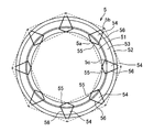
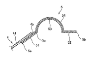
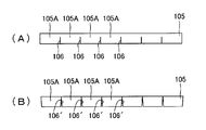
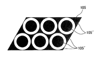
- FIG. 1 It is sectional drawing which shows the speaker concerning one Example of this invention. It is a perspective view of the edge for speakers which constitutes the speaker shown in FIG. It is a top view which shows the structure of the edge for speakers shown by FIG. It is a figure which expands and shows the edge for speakers shown in FIG. It is a figure for demonstrating the manufacturing method of the edge for speakers shown by FIG. It is a figure for demonstrating the manufacturing method of the conventional speaker edge shape
- (I) shows the simulation result of the rigidity change from the cone paper to the edge of the conventional speaker and the speaker of the present invention
- (ii) is a cross-sectional view showing the cone paper and the edge of the speaker shown in FIG.
- (Iii) is a cross-sectional view showing a cone paper and an edge of a speaker as a conventional product.
- (A) is sectional drawing which shows the structure of the edge for speakers described in patent document 1
- (B) is sectional drawing which follows the II line
- (C) is (A 2 is a cross-sectional view taken along line II-II in FIG.
- the speaker edge according to an embodiment of the present invention is a speaker edge formed in a substantially ring shape by a plurality of base materials, and a part of the adjacent base material is overlapped on both ends of each base material. Since the circumferential length of the overlapping portion gradually decreases from the specific position between the inner edge portion and the outer edge portion toward the outer side in the radial direction, the overlapping portion in the circumferential direction in the overlapping portion of the edges is provided. When the diaphragm is fixed at the position where the length is the longest (specific position) or in the vicinity thereof, the diaphragm is fixed at the position where the rigidity is highest at the edge or in the vicinity thereof.
- the rigidity does not change abruptly, and the change becomes gradual.
- the rigidity of the overlapping portion becomes smaller toward the outer edge portion, it is possible to gradually attenuate the vibration from the diaphragm transmitted to the edge, and to suppress the occurrence of unnecessary resonance due to the portion.
- the overlapping portion is thicker than the portion that is not the overlapping portion, it can exhibit excellent responsiveness to a sound current with a large amplitude, and the portion that is not the overlapping portion is easily elastically deformed and has a small amplitude. Excellent response to voice current.
- the overlapping portion and the portion that is not the overlapping portion are alternately provided in the circumferential direction at the edge, it can vibrate reliably in a band from a sound current having a small amplitude to a sound current having a large amplitude. Thereby, the acoustic characteristics of the speaker can be improved.
- the speaker edge has an odd number of a plurality of base materials. Since the frequency of generating unnecessary resonance can be varied in the circumferential direction of the edge by the odd number of the plurality of base materials, unnecessary resonance occurs compared to the case where the number of base materials is an even number. Suppression can be achieved.
- the plurality of overlapping portions are formed in the same shape symmetrical with respect to the circumferential direction of the speaker edge, and further formed in the same shape symmetrical with respect to the circumferential direction of the speaker edge.
- the plurality of overlapping portions are arranged at equal intervals in the circumferential direction of the edge, so that the appearance of the speaker edge can be aesthetically pleasing.
- the appearance of the speaker edge can be made beautiful.
- the cross-sectional shape is a convex shape, and has a convex top between the outer edge and the specific position.
- the diaphragm is fixed at a position (specific position) where the circumferential length is the longest in the overlapping portion of the edge or in the vicinity thereof, the top of the convex shape is radially outward from the position where the rigidity is highest at the edge Therefore, since the vibration from the diaphragm transmitted to the edge passes through the top after passing through a specific position, the vibration transmitted to the edge is surely attenuated, and unnecessary resonance caused by the location is generated. Can be reliably suppressed.
- the short direction and the one end in the short direction are left.
- a split part forming step in which a plurality of slits are provided to form a plurality of split parts
- a polygonal shape forming step in which adjacent split parts are fixed in a superposed state to form a polygonal shape. Therefore, the amount of waste material can be reduced compared to the case of manufacturing the speaker edge by punching the base material like the conventional edge, so the amount of material to be prepared in advance can be reduced. In addition to reducing material costs, it can also contribute to resource saving.
- the appearance of the speaker edge can be made beautiful and the sound quality can be changed.
- an inner edge cutting step for cutting the inner edge of the polygon so as to form a circle after the polygon shape forming step, before the polygon shape forming step or simultaneously with the polygon shape forming step.
- the appearance of the speaker edge can be made beautiful and the sound quality can be changed.
- the speaker has a frame 2, a magnetic circuit unit 3 supported by the frame 2, and a voice coil 40 that is arranged in the magnetic circuit unit 3 and vibrates when an audio current is supplied.
- the oscillating part 4 having the cone paper 41 (diaphragm) to be propagated, and the inner edge part 5a is fixed to the cone paper 41 and the outer edge part 5b is fixed to the frame 2 to support the cone paper 41.
- Edge 5 edge for speaker
- the frame 2 is continued to an annular bottom wall 21, a frustum-shaped peripheral wall 22 continuous to the outer edge of the bottom wall 21, and an outer edge away from the bottom wall 21 of the peripheral wall 22. And a flange portion 23 extending outward.
- the frustum-shaped peripheral wall 22 is provided with a diameter increasing toward the acoustic radiation direction side.
- the outer edge portion 5 b of the edge 5 is fixed to the flange portion 23.
- the acoustic radiation direction is a direction indicated by one side of the virtual central axis of the frame 2 (hereinafter referred to as a virtual central axis of the speaker 1 and indicated by a symbol P), and is shown above the paper surface direction in FIG. Direction.
- the magnetic circuit unit 3 is formed in an annular shape, and has a bottom plate 34 arranged in parallel with the bottom wall 21 of the frame 2, and a cylindrical shape from the inner edge of the bottom plate 34 to the acoustic radiation direction side. And a magnet 31 that is formed in an annular shape, is inserted in the center pole 35 and overlaps the bottom plate 34, and an annular shape. And a top plate 33 that is superimposed on the magnet 32 with the center pole 35 inserted therethrough.
- the yoke 31, the magnet 32, and the top plate 33 are made of a magnetic material and are arranged coaxially with the virtual central axis P of the speaker 1.
- a voice coil 40 to be described later is disposed between the inner periphery of the top plate 33 and the outer periphery of the center pole 35.
- Such a magnetic circuit unit 3 generates a magnetic force for driving cone paper 41 (described later) in cooperation with the voice coil 40 described later between the center pole 35 and the top plate 33 of the yoke 31.
- a magnetic gap G is formed.
- the magnetic circuit unit 3 applies an electromagnetic force (Lorentz force) to the voice coil 40 in the magnetic gap G.
- the magnetic circuit unit 3 applies an electromagnetic force (Lorentz force) to the voice coil 40, so that the cone paper 41 vibrates and the speaker 1 generates sound.
- the vibration unit 4 includes a voice coil 40 that vibrates when supplied with an audio current, a cone paper 41, a cylindrical voice coil bobbin 42 that propagates vibration from the voice coil 40 to the cone paper 41, a center cap 43, a voice And a damper 44 for supporting the coil bobbin 42 with respect to the frame 2.
- the cone paper 41 is formed in a frustum shape whose diameter increases toward the acoustic radiation direction side.
- the cone paper 41 has an inner edge fixed to one axial end (acoustic radiation direction side) of the voice coil bobbin 42 and an outer edge fixed to the edge 5 so as to be coaxial with the virtual central axis P of the speaker 1. Has been placed.
- the voice coil bobbin 42 is formed in a cylindrical shape, and a center pole 35 is inserted therein.
- the voice coil bobbin 42 is wound with a voice coil 40 in the vicinity of the other end portion in the axial direction (on the side opposite to the acoustic radiation direction).
- the center cap 43 is made of synthetic resin.
- the center cap 43 is formed in a disk shape in plan view, and a cross-sectional shape is formed in a convex arc shape toward the acoustic radiation direction side.
- the center cap 43 is attached to the voice coil bobbin 42 so as to close the opening on the other end side of the voice coil bobbin 42.
- the damper 44 is configured to be elastically deformable from an insulating material and is formed in an annular shape.
- the damper 44 has an inner edge fixed to the other end of the voice coil bobbin 42, and an outer edge fixed to the peripheral wall 22 of the frame 2.
- the edge 5 is made of elastic synthetic rubber.
- the edge 5 is provided between the cone paper 41 and the frame 2, and the vibration from the cone paper 41 is propagated. In order to attenuate the vibration from the cone paper 41, the edge 5 is deformed into the cone paper 41. It is attached freely.
- the edge 5 includes a belt-like inner peripheral bonding portion 51 including an inner edge portion 5 a fixed to the cone paper 41 and a belt-like shape including an outer edge portion 5 b fixed to the frame 2.
- the inner periphery bonding part 51 and the outer periphery bonding part 52 are formed flat.
- the protruding portion 53 is provided on the entire circumference of the edge 5.
- the edge 5 in this embodiment is made of synthetic rubber, but the present invention is not limited to this, and the edge 5 may be made of paper, cloth, leather, foamed urethane, polymer You may be comprised from synthetic resins, such as a film and thermoplastic vinyl. That is, the edge 5 only needs to be made of an elastic material so that vibration from the cone paper 41 can propagate.
- the edge 5 is provided with the protrusion 53 formed so as to protrude toward the sound radiation direction of the speaker 1, but the present invention is not limited to this, and the protrusion 5 projects toward the sound radiation direction. It may replace with the protruding part 53 of this and may be formed in the concave from the acoustic radiation direction of the speaker 1. Moreover, it may replace with the protruding ridge part 53 toward the acoustic radiation direction, and may be formed in the bellows shape by which the unevenness
- the edge 5 is arranged such that a plurality of rectangular plate-like (rectangular plate-like) base materials 50 having the same shape are arranged in an annular shape, and one end portion of each adjacent base material 50 in the longitudinal direction. It is configured to be fixed in a state where they are overlapped with each other. As will be described in detail later, the inner and outer edges thereof are cut so that the overall shape forms an annular shape. At both ends of each base material 50 in the longitudinal direction, an overlapping portion 54 in which a part of the adjacent base material 50 is overlapped is provided. In other words, a plurality of overlapping portions 54 are provided, and the plurality of overlapping portions 54 are provided at equal intervals in the circumferential direction of the edge 5.
- the overlapping portion 54 is formed to have a thickness twice that of the portion that is not the overlapping portion 54 (that is, the portion other than the overlapping portion 54 in the edge 5), and has the same polygonal shape that is symmetrical in the circumferential direction of the edge 5. Is formed.
- each overlapping portion 54 has a gradually increasing portion 55 whose length in the circumferential direction gradually increases from the inner edge portion (the inner edge portion 5a of the edge 5) toward the outer side in the radial direction of the edge 5, A gradual decrease portion 56 that is continuous with the gradual increase portion 55 and whose length in the circumferential direction gradually decreases toward the outer side in the radial direction is integrally provided.
- the position (henceforth the specific position 5c) of the overlapping part 54 has the largest length of the circumferential direction is located in the boundary part of the gradually increasing part 55 and the gradually decreasing part 56, it is the inner periphery bonding part 51. 4 and is fixed so that the outer edge 4b of the cone paper 41 overlaps as shown in FIG.
- the cone paper 41 is fixed to a position of the overlapping portion 54 having the longest circumferential length, that is, the specific position 5c.
- the gradually decreasing portion 56 is provided across the inner peripheral bonding portion 51, the protruding portion 53, and the outer peripheral bonding portion 52.
- the edge 5 starts from the specific position 5c where the overlapping portion 54 has the largest circumferential length among the overlapping portions 54 between the inner edge portion 5a and the outer edge portion 5b of the edge 5. Since the length in the circumferential direction is gradually reduced toward the outer side in the radial direction, the outer edge 4b of the cone paper 41 is located at or near the specific position 5c where the circumferential length of the overlapping portion 54 of the edge 5 is the largest.
- the cone paper 41 is fixed at the specific position 5c having the highest rigidity at the edge 5 or in the vicinity thereof. Therefore, the rigidity of the cone paper 41 from the cone paper 41 to the edge 5 is conventionally increased. The change will be slow without a sudden change.
- the overlapping portion 54 since the rigidity of the overlapping portion 54 becomes smaller toward the outer edge portion 5b, the vibration from the cone paper 41 transmitted to the edge 5 is gradually attenuated to suppress generation of unnecessary resonance caused by the portion. be able to.
- the overlapping portion 54 since the overlapping portion 54 is thicker than the portion that is not the overlapping portion 54, the overlapping portion 54 can exhibit excellent responsiveness to a sound current having a large amplitude, and the portion that is not the overlapping portion 54 is easily elastically deformed. Excellent responsiveness can be exhibited even for audio current with small amplitude.
- the overlapping portion 54 and the portion that is not the overlapping portion 54 are alternately provided in the circumferential direction at the edge 5, it can vibrate reliably in a band from a sound current having a small amplitude to a sound current having a large amplitude. it can. Thereby, the acoustic characteristics of the speaker 1 can be improved.
- a slit 106 is provided at a position equidistant in the longitudinal direction of the strip-shaped base material 105 along the short direction and leaving one end in the short direction.
- a plurality of divided portions 105A are formed by forming a plurality (corresponding to a divided portion forming step). At this time, the slits 106 are formed so that the plurality of divided portions 105A are an odd number.
- the notch 106 ′ may be formed so that the plurality of divided portions 105A are an odd number.
- a notch shape such as the notch portion 106 ′ is also included in the concept of “slit” in the present invention.
- the edge 5 of the present embodiment is composed of an odd number of dividing sections 105A, the edge 5 may be composed of an even number of dividing sections 105A.
- the overlapped portions are fixed with an adhesive to form a polygonal shape in which the overall shape is an annular shape (in the polygonal shape forming step). Equivalent to).
- the inner periphery bonding part 51, the outer periphery bonding part 52, and the protrusion part 53 may be formed, the inner periphery bonding part 51, the outer periphery bonding part 52, And the polygonal outer edge part which has the protrusion part 53 cut
- the edge 5 is produced by forming the overlapping portion 54.
- the outer edge may be cut, or the polygonal inner edge and the outer edge may be cut simultaneously.
- the outer edge cutting step and the inner edge cutting step are performed after the polygonal shape forming step, but in the present invention, the outer edge cutting step and the inner edge cutting step may be omitted.
- the obtained speaker edge 5 is located at a position spaced from each other in the longitudinal direction of the strip-shaped base material 105 along the short direction and one end in the short direction.
- the amount of the waste material 105 ′ is larger than that in the case where an annular speaker edge is manufactured by punching the sheet-like base material 105 as shown in FIG. This reduces the amount of material to be prepared in advance, which can reduce material costs and contribute to resource saving.
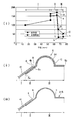
- FIG. 7 (i) shows the simulation result
- FIG. 7 (ii) is a cross-sectional view showing the cone paper 41 and the edge 5 of the speaker 1 described in the embodiment as the product of the present invention.
- FIG. 7 (iii) is a cross-sectional view showing a cone paper 41 and an edge 215 of a speaker as a conventional product.
- the present invention product and the conventional product use cone paper 41 having the same material and the same thickness.
- the edge 215 of the conventional product is formed so that the thickness is uniform over the radial direction and the entire circumferential direction, and the edge 5 of the present invention is made of the same material.
- FIG. 7 (i) shows the length which goes to the radial direction outer side from the virtual center axis P of the speaker 1, and a vertical axis
- shaft is thickness of the circumferential direction as this invention and a comparative example.
- a section I in FIG. 7 (i) is a portion corresponding to the section I in FIGS. 7 (ii) and (iii), and shows a change in the rigidity of the cone paper 41.
- a section II in FIG. 7 (i) is a portion corresponding to the section II in FIGS.
- a section III in FIG. 7 (i) is a portion corresponding to the section III in FIGS. 7 (ii) and (iii), and shows a change in rigidity of the edge 5 and the edge 215.
- a point A in FIG. 7 (i) is a portion corresponding to the point A of the product of the present invention in FIG. 7 (ii), and a position where the length in the circumferential direction of the overlapping portion 54 is the largest (specific position 5c).
- the outer edge portion 4b of the cone paper 41 are shown to be rigid.
- a point B in FIG. 7 (i) is a portion corresponding to the point B in FIG. 7 (ii), and the circumferential length of the overlapping portion 54 of the edge 5 is larger than the circumferential length at the point A.
- a point C in FIG. 7 (i) corresponds to the point C in FIG. 7 (ii), and the circumferential length of the overlapping portion 54 of the edge 5 is greater than the circumferential length at the point B.
- the rigidity at a small position is a small position.
- a point a in FIG. 7 (i) is a portion corresponding to the point a of the comparative example in FIG. 7 (iii), and shows the rigidity of the portion where the edge 215 and the cone paper 204 overlap.
- a point b in (i) is a portion corresponding to the point b in FIG. 7 (iii), and shows the rigidity of only the edge 215, and a point c in FIG. 7 (i) is in FIG. 7 (iii). This is a portion corresponding to the point c, and shows the rigidity on the outer side in the radial direction from the point b.
- the rigidity change from the point A to the point B of the product of the present invention is small with respect to the rigidity change from the point a to the point b in the comparative example, that is, from the point a to the point b in the comparative example. It was found that the rigidity change from point A to point B of the product of the present invention is more gradual than the rigidity change. From this, it was clarified that the product of the present invention can attenuate the vibration from the cone paper 41 transmitted to the edge 5 more gradually than the comparative example, and can suppress the occurrence of unnecessary resonance due to the location. . It was also found that the stiffness at point C was reduced compared to the stiffness at point B.
- the cone paper 41 is fixed to a position (the specific position 5c) where the rigidity is the highest in the edge 5.
- the change from the paper 41 to the edge 5 does not change abruptly, and the change becomes gradual.
- the rigidity of the overlapping portion 54 decreases toward the outer edge portion, it is possible to gradually attenuate the vibration from the cone paper 41 transmitted to the edge 5 to suppress the occurrence of unnecessary resonance caused by the location. it can.
- the overlapping portion 54 is thicker than the portion that is not the overlapping portion 54, the overlapping portion 54 can exhibit excellent responsiveness to a sound current having a large amplitude, and the portion that is not the overlapping portion 54 is easily elastically deformed.
- the overlapping portion 54 and the portion that is not the overlapping portion 54 are alternately provided in the circumferential direction at the edge 5, it can vibrate reliably in a band from a sound current having a small amplitude to a sound current having a large amplitude. it can. Thereby, the acoustic characteristics of the speaker 1 can be improved.
- the strip-shaped base material 105 is spaced apart from each other in the longitudinal direction along the short direction and one end in the short direction.
- the following speaker edge 5, speaker 1, and speaker edge manufacturing method can be obtained.
- the speaker 1 comprising the speaker edge according to claim 1 or 2, and the speaker edge according to claim 1, wherein an inner edge portion is fixed to the cone paper 41 and an outer edge portion is fixed to the frame 2. Because The speaker 1, wherein an outer edge portion 4 b of the cone paper 41 is fixed at or near the specific position 5 c.
- a plurality of slits 106 are provided at positions spaced apart from each other in the longitudinal direction of the strip-shaped base material 105, along the short direction and leaving one end in the short direction.
- a method for manufacturing an edge for a speaker comprising: a polygonal shape forming step of forming a polygonal shape by fixing adjacent divided portions 105A in a state of being overlapped with each other.
- the speaker edge 5, the speaker 1, and the speaker edge that can suppress the occurrence of unnecessary resonance, improve the acoustic characteristics, and reduce the material cost are provided.
- a manufacturing method can be provided.
Landscapes
- Engineering & Computer Science (AREA)
- Physics & Mathematics (AREA)
- Acoustics & Sound (AREA)
- Signal Processing (AREA)
- Manufacturing & Machinery (AREA)
- Multimedia (AREA)
- Diaphragms For Electromechanical Transducers (AREA)
Description
本発明は、スピーカ、及びスピーカ用エッジに関するものである。
従来のスピーカは、フレームと、フレームに支持される磁気回路部と、磁気回路部内に配置されて音声電流が供給されると振動するボイスコイルの振動が伝播される振動板と、フレームと振動板との間に設けられて、内縁部が振動板に固着されるとともに外縁部がフレームに固着されて振動板を支持するエッジと、を備えている。このような従来のエッジは、均一の厚みを持つシート状の材料を打ち抜くことで、その周方向に均一の厚みに形成されていた。
ところで、上述した従来のエッジは、その全周に亘って均一の厚みに形成されていたから、その厚みを比較的厚めにして、振動板を支持するための強度を確保していた。このため、従来のエッジは、弾性変形し難くなり、振幅の小さな音声電流に対して所望でない反射や振動伝播ロスが生じてしまうことがあった。そこで、従来のエッジの厚みを薄くすることで、弾性変形し易くして、所望でない反射や振動伝播ロスを抑制させることを試みていたが、従来のエッジの厚みを薄くすると振動板を支持するための強度を確保できなかった。即ち、振幅の小さな音声電流に対しても振動伝播して応答性を発揮させることと、振動板を支持するための強度を確保することを両立させることが困難であった。
上述した問題を解決するエッジが特許文献1に開示されている。特許文献1に開示されたエッジは、図8(A)に示すように、円環状に形成されているとともに、その周方向に厚みが厚い厚肉部205Aと、厚肉部205Aよりも厚みが薄い薄肉部205Bと、が交互に設けられている。厚肉部205A及び、薄肉部205Bは、エッジ205の径方向外側に向かうに従って周方向の長さが大きくなる扇形状に形成されている。このようなエッジ205は、厚肉部205Aと薄肉部205Bとが、その周方向に交互に設けられているから、厚肉部205Aが、図8(B)に示すように、振幅の大きな音声電流に対しても振動伝播して応答性を発揮させることができ、かつ振動板204を支持するための強度を確保しつつ、薄肉部205Bが、図8(C)に示すように、振幅の小さな音声電流に対しても振動伝播して応答性を発揮させることができるから、振動板204を支持するための強度を確保しつつ、振幅の小さな音声電流から振幅の大きな音声電流までの帯域において振動板204が確実に振動するため、スピーカの音響特性の向上が図られていた。
しかしながら、特許文献1に開示されたエッジ205において、厚肉部205A及び、薄肉部205Bは、エッジ205の径方向外側に向かうに従って周方向の長さが大きくなる扇形状に形成されているから、厚肉部205A及び、薄肉部205Bは、その径方向の
何れの位置においても周方向比率が等しいこととなり、よって、エッジの剛性は、内縁部から外縁部まで略等しいから、振動板204がエッジ205の内縁部に固着されると、振動板204からエッジ205へと、その剛性が急激に変化することとなり、振動板204からの振動を徐々に減衰させるようにエッジ205に伝播することができず、このため、不要共振を発生させてしまうという懸念がある。
何れの位置においても周方向比率が等しいこととなり、よって、エッジの剛性は、内縁部から外縁部まで略等しいから、振動板204がエッジ205の内縁部に固着されると、振動板204からエッジ205へと、その剛性が急激に変化することとなり、振動板204からの振動を徐々に減衰させるようにエッジ205に伝播することができず、このため、不要共振を発生させてしまうという懸念がある。
本発明は、このような問題点に対処することを課題の一例とするものである。即ち、本発明は、不要共振発生の抑制を図るとともに、音響特性の向上を図ることができるスピーカ、及びスピーカ用エッジを提供することを目的としている。
上記課題を解決するために、請求項1に記載のスピーカ用エッジは、複数の基材によって略環状に形成されたスピーカ用エッジであって、前記各基材の両端部には、隣接した前記基材の一部が重ねられた重なり部が設けられ、前記重なり部は、内縁部と外縁部との間の特定位置から径方向外側に向かうに従ってその周方向の長さが漸減していることを特徴としている。
請求項7に記載のスピーカは、フレームと、該フレームに支持される磁気回路部と、該磁気回路部内に配置されて音声電流によって振動するボイスコイルの振動が伝播される振動板と、内縁部が前記振動板に固着されるとともに外縁部が前記フレームに固着される請求項1又は、請求項2記載のスピーカ用エッジと、を備えたスピーカであって、前記特定位置又はその近傍に前記振動板の外縁部が固着されることを特徴としている。
請求項8に記載のスピーカ用エッジの製造方法は、帯状の母材の長手方向に互いに間隔をあけた位置に、その短手方向に沿うとともにその短手方向の一端を残した複数のスリットを設けて複数の分割部を形成する分割部形成工程と、隣接した前記分割部を互いに重ね合わせた状態で固定して、多角形状に形成する多角形状形成工程と、を備えたことを特徴としている。
以下、本発明の一実施形態にかかるスピーカ用エッジ、及びスピーカについて説明する。本発明の一実施形態にかかるスピーカ用エッジは、複数の基材によって略環状に形成されたスピーカ用エッジであって、各基材の両端部には、隣接した基材の一部が重ねられた重なり部が設けられ、重なり部は、内縁部と外縁部との間の特定位置から径方向外側に向かうに従ってその周方向の長さが漸減しているから、エッジの重なり部における周方向の長さが最も大きい位置(特定位置)又はその近傍に振動板が固着された場合には、エッジにおいて剛性が最も高い位置又はその近傍に振動板が固着されることとなり、よって、従来のように、振動板からエッジへと、その剛性が急激に変化することなく、その変化が緩やかになる。また、重なり部の剛性は、その外縁部に向かうに従って小さくなるから、エッジに伝わる振動板からの振動を徐々に減衰させて、その箇所に起因する不要共振発生の抑制を図ることができる。また、重なり部は、重なり部でない部分よりも厚みが厚い分、振幅の大きな音声電流に対しても優れた応答性を発揮できるとともに、重なり部でない部分は、弾性変形し易くなり、振幅の小さな音声電流に対しても優れた応答性を発揮できる。さらに、重なり部と、重なり部でない部分は、エッジにおける周方向に交互に設けられているから、振幅の小さな音声電流から振幅の大きな音声電流までの帯域において、確実に振動することができる。これにより、スピーカの音響特性の向上を図ることができる。
また、スピーカ用エッジは、複数の基材が、奇数個であることが好ましい。複数の基材が、奇数個であることで、不要共振を発生させる周波数をエッジの周方向にばらつかせることができるので、基材の数が偶数個である場合に比べて不要共振発生の抑制を図ることができる。
また、複数の基材が同形状であるから、複数の重なり部は、スピーカ用エッジの周方向に対称な同形状に形成され、さらに、スピーカ用エッジの周方向に対称な同形状に形成された複数の重なり部が、エッジの周方向に等間隔をあけて配置されることとなり、スピーカ用エッジの外観を美観にすることができる。
また、複数の重なり部が同形状であるから、スピーカ用エッジの外観を美観にすることができる。
また、断面形状が凸形状であり、外縁部と特定位置の間に凸形状の頂部を有するから、
エッジの重なり部における周方向の長さが最も大きい位置(特定位置)又はその近傍に振動板が固着された場合には、エッジにおいて剛性が最も高い位置よりも、径方向外側に凸形状の頂部が設けられることとなり、よって、エッジに伝わる振動板からの振動が、特定位置を通過した後、頂部を通過するから、エッジに伝わる振動を確実に減衰して、その箇所に起因する不要共振発生の抑制を確実に図ることができる。
エッジの重なり部における周方向の長さが最も大きい位置(特定位置)又はその近傍に振動板が固着された場合には、エッジにおいて剛性が最も高い位置よりも、径方向外側に凸形状の頂部が設けられることとなり、よって、エッジに伝わる振動板からの振動が、特定位置を通過した後、頂部を通過するから、エッジに伝わる振動を確実に減衰して、その箇所に起因する不要共振発生の抑制を確実に図ることができる。
また、本発明の一実施形態にかかるスピーカ用エッジの製造方法は、帯状の母材の長手方向に互いに間隔をあけた位置に、その短手方向に沿うとともにその短手方向の一端を残した複数のスリットを設けて複数の分割部を形成する分割部形成工程と、隣接した分割部を互いに重ね合わせた状態で固定して、多角形状に形成する多角形状形成工程と、を順次行い製造されるから、従来のエッジのように母材に打ち抜き加工を施すことでスピーカ用エッジを製造する場合と比べて、廃材の量を減らすことができるから、予め準備する材料の量を減らすことができ、資材コストを低減することができるとともに、省資源化にも貢献することができる。
また、多角形状形成工程の後、多角形状の外縁を、円を成すように切断する外縁切断工程をさらに備えることで、スピーカ用エッジの外観を美観にするとともに、音質を変化させることができる。
また、外縁切断工程を備える場合には、多角形状形成工程の後、多角形状形成工程の前、又は多角形状形成工程と同時に、多角形状の内縁を、円を成すように切断する内縁切断工程をさらに備えることで、スピーカ用エッジの外観を美観にするとともに、音質を変化させることができる。
以下、本発明のスピーカ用エッジ、及びスピーカの一実施例を図1乃至図5に基づいて説明する。スピーカは、図1に示すように、フレーム2と、フレーム2に支持される磁気回路部3と、磁気回路部3内に配置されて音声電流が供給されると振動するボイスコイル40の振動が伝播されるコーン紙41(振動板)を有する振動部4と、円環状に形成されて内縁部5aがコーン紙41に固着されるとともに外縁部5bがフレーム2に固着されてコーン紙41を支持するエッジ5(スピーカ用エッジ)と、を備えている。
フレーム2は、図1に示すように、円環状の底壁21と、底壁21の外縁に連続される錐台状の周壁22と、周壁22の底壁21から離れた外縁に連続されるとともに外側方向に延在するフランジ部23と、で構成されている。錐台状の周壁22は、音響放射方向側に向かうに従って拡径して設けられている。フランジ部23には、エッジ5の外縁部5bが固着される。ここで、音響放射方向は、フレーム2の仮想中心軸(以下、スピーカ1の仮想中心軸と記し、符号Pを記す)方向の一方側が示す方向であり、図1中の紙面方向の上方が示す方向である。
磁気回路部3は、図1に示すように、円環状に形成されて、フレーム2の底壁21と平行に配置されるボトムプレート34及び、ボトムプレート34の内縁から音響放射方向側に筒状に立設したセンターポール35、を一体に備えて構成されたヨーク31と、円環状に形成されていて、その内側にセンターポール35が挿通されてボトムプレート34に重ねられる磁石32と、円環状に形成されていて、その内側にセンターポール35を挿通させた状態で磁石32に重ねられるトッププレート33と、を備えている。ヨーク31、磁石32、及びトッププレート33は、磁性体で構成されているとともに、スピーカ1の仮想中心軸Pと同軸に配置されている。トッププレート33の内周部とセンターポール35の外周部との間には、後述するボイスコイル40が配置される。
このような磁気回路部3は、ヨーク31のセンターポール35とトッププレート33との間に、後述するボイスコイル40と協働してコーン紙41(後述する)を駆動するための磁力を発生する磁気ギャップGを形成する。換言すると、磁気回路部3は、磁気ギャップG内にて、ボイスコイル40に電磁気力(ローレンツ力)を作用させる。そして、磁気回路部3は、ボイスコイル40に電磁気力(ローレンツ力)を作用させることで、コーン紙41が振動し、スピーカ1は音を発生する。
振動部4は、音声電流が供給されて振動するボイスコイル40と、コーン紙41と、ボイスコイル40からの振動をコーン紙41に伝播する円筒状のボイスコイルボビン42と、センターキャップ43と、ボイスコイルボビン42をフレーム2に対して支持するためのダンパ44と、を備えている。
コーン紙41は、音響放射方向側に向かうに従って拡径する錘台状に形成されている。このコーン紙41は、その内縁部がボイスコイルボビン42の軸方向の一端部(音響放射方向側)に固定され、その外縁部がエッジ5に固着されて、スピーカ1の仮想中心軸Pと同軸に配置されている。
ボイスコイルボビン42は、円筒状に形成されて、その内側にセンターポール35が挿入されている。このボイスコイルボビン42は、その軸方向の他端部(音響放射方向反対側)近傍に、ボイスコイル40が巻き回されていている。
センターキャップ43は、合成樹脂で構成されている。このセンターキャップ43は、その平面視が円板状で、かつその断面形状が音響放射方向側に向かって凸の円弧状に形成されている。このセンターキャップ43は、ボイスコイルボビン42の他端部側の開口を塞いだ格好でボイスコイルボビン42に取り付けられている。
ダンパ44は、絶縁性の材料から弾性変形自在に構成されているとともに、円環状に形成されている。このダンパ44は、その内縁部がボイスコイルボビン42の他端部に固定され、その外縁部が、フレーム2の周壁22に固定される。
エッジ5は、弾性を有する合成ゴムから構成されている。このエッジ5は、コーン紙41とフレーム2との間に設けられて、コーン紙41からの振動が伝播されるものであり、コーン紙41からの振動を減衰させるために、コーン紙41に変形自在に取り付けられている。また、エッジ5は、図1、図2に示すように、コーン紙41に固着される内縁部5aを含む帯状の内周貼合部51と、フレーム2に固着される外縁部5bを含む帯状の外周貼合部52と、内周貼合部51と外周貼合部52の間に設けられているとともに、その断面形状がスピーカ1の音響放射方向側に向かって凸の円弧状に形成された突条部53と、を備えて構成されている。内周貼合部51及び、外周貼合部52は、平坦に形成されている。突条部53はエッジ5の全周に設けられている。
本実施例のエッジ5は、合成ゴムから構成されているが、本発明はこれに限ったものではなく、エッジ5は、紙、布、革から構成されていてもよく、発泡ウレタン、高分子フィルム、熱可塑性ビニールなどの合成樹脂から構成されていてもよい。即ち、エッジ5は、コーン紙41からの振動が伝播可能なように弾性を有する材料から構成されていればよい。また、エッジ5には、スピーカ1の音響放射方向に向かって凸に形成された突条部53が設けられていたが、本発明はこれに限ったものではなく、音響放射方向に向かって凸の突条部53に代えて、スピーカ1の音響放射方向から凹に形成されていてもよい。また、音響放射方向に向かって凸の突条部53に代えて、凹凸が交互に形成された蛇腹状に形成されていてもよい。
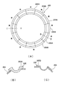
このエッジ5は、図2に示すように、複数の同形状の矩形板状(長方形板状)の基材50が環状を成すように並べられ、隣接した各基材50の長手方向の一端部同士が互いに重ね合された状態で固定されて構成され、詳しくは、後述するように、その内外縁が切断されて、その全体形状が円環状を成すように形成されている。各基材50の長手方向の両端部には、隣接した基材50の一部が重ねられた重なり部54が設けられている。換言すると、重なり部54は複数設けられ、複数の重なり部54は、エッジ5の周方向に等間隔をあけて設けられている。また、重なり部54は、重なり部54でない部分(即ち、エッジ5における重なり部54以外の部分)の2倍の厚みに形成されているとともに、エッジ5の周方向に対称な同形状の多角形状に形成されている。
各重なり部54は、図3に示すように、その内縁部(エッジ5の内縁部5a)から、エッジ5の径方向の外側に向かうに従ってその周方向の長さが漸増する漸増部55と、漸増部55に連続されるとともに、径方向の外側に向かうに従ってその周方向の長さが漸減する漸減部56と、を一体に備えて構成されている。また、重なり部54のうち、周方向の長さが最も大きい位置(以下、特定位置5cと記す)は、漸増部55と漸減部56との境界部に位置するとともに、内周貼合部51に設けられていて、図4に示すように、コーン紙41の外縁部4bが重なるように固着される。即ち、重なり部54のうちその周方向の長さが最も大きい位置、即ち特定位置5cにコーン紙41が固着されている。漸減部56は、内周貼合部51、突条部53、及び外周貼合部52に亘って設けられている。
上述したスピーカ1によれば、エッジ5は、その重なり部54が、エッジ5の内縁部5aと外縁部5bとの間の重なり部54のうち、周方向の長さが最も大きい特定位置5cから径方向外側に向かうに従ってその周方向の長さが漸減されているから、エッジ5の重なり部54における周方向の長さが最も大きい特定位置5c、又はその近傍にコーン紙41の外縁部4bが固着された場合には、エッジ5において剛性が最も高い特定位置5c、又はその近傍にコーン紙41が固着されることとなり、よって、従来のように、コーン紙41からエッジ5へと、その剛性が急激に変化することなく、その変化が緩やかになる。また、重なり部54は、その剛性が、外縁部5bに向かうに従って小さくなるから、エッジ5に伝わるコーン紙41からの振動を徐々に減衰させて、その箇所に起因する不要共振発生の抑制を図ることができる。また、重なり部54は、重なり部54でない部分よりも厚みが厚い分、振幅の大きな音声電流に対しても優れた応答性を発揮できるとともに、重なり部54でない部分は、弾性変形し易くなり、振幅の小さな音声電流に対しても優れた応答性を発揮できる。さらに、重なり部54と、重なり部54でない部分は、エッジ5における周方向に交互に設けられているから、振幅の小さな音声電流から振幅の大きな音声電流までの帯域において、確実に振動することができる。これにより、スピーカ1の音響特性の向上を図ることができる。
続いてエッジ5の製造方法について、図5を参照して説明する。まず、図5(A)に示すように、帯板状の母材105の長手方向に等間隔をあけた位置に、その短手方向に沿うとともにその短手方向の一端を残したスリット106を複数設けて、複数の分割部105Aを形成する(分割部形成工程に相当する)。この際、複数の分割部105Aが、奇数個になるようにスリット106を形成する。又は、図5(B)に示すように、複数の分割部105Aが、奇数個になるように切欠き部106´を形成してもよい。尚、切欠き部106´の如き切欠形状も、本発明において「スリット」の概念に含まれるものとする。また、本実施例のエッジ5は、奇数個の分割部105Aから構成されているが、エッジ5は、偶数個の分割部105Aから構成されていてもよい。
そして、隣接した分割部105Aの他端同士を互いに重ね合わせた状態で、重ね合わせた部分を接着剤を用いて固着して、全体形状が環状を成す多角形状に形成する(多角形状形成工程に相当する)。この後、内周貼合部51、外周貼合部52、及び突条部53を形成するように、多角形状にプレス加工を施した後、内周貼合部51、外周貼合部52、及び突条部53を有する多角形状の外縁部が円を成すように切断し(外縁切断工程に相当する)、この後、多角形状の内縁部が円を成すように切断し(内縁切断工程に相当する)、重なり部54を成形して、エッジ5を製造する。又は、多角形状の内縁を切断した後、その外縁を切断してもよく、多角形状の内縁と外縁とを同時に切断してもよい。
上述した実施例では、多角形状形成工程の後、外縁切断工程、及び内縁切断工程を実施していたが、本発明では、外縁切断工程、及び内縁切断工程を省略してもよい。
上述したエッジ5の製造方法によれば、得られたスピーカ用エッジ5は、帯状の母材105の長手方向に互いに間隔をあけた位置に、その短手方向に沿うとともにその短手方向の一端を残したスリット106を複数設けて複数の分割部105Aを形成する分割部形成工程と、隣接した分割部105Aの他端同士を互いに重ね合わせた状態で固定して多角形状を形成する多角形状形成工程と、を順次行い製造されるから、図6に示すように、シート状の母材105に打ち抜き加工を施すことで円環状のスピーカ用エッジを製造する場合と比べて、廃材105´の量を減らすことができ、予め準備する材料の量を減らすこととなり、資材コストを低減することができるとともに、省資源化にも貢献することができる。
次に、本発明の発明者らは、本発明品、及び比較例として、その厚みが径方向、及び全周方向に亘って均一に成るように形成されたエッジを有する従来品、のコーン紙の内縁部の剛性(ヤング率)を100とした場合の、コーン紙からエッジの外縁部までの剛性変化をシミュレーションして、本発明の効果を確認した。ここで、図7(i)は、シミュレーション結果を示し、図7(ii)は、本発明品として、実施例に記載されたスピーカ1のコーン紙41、及びエッジ5を示す断面図であり、図7(iii)は、従来品としてのスピーカのコーン紙41、及びエッジ215を示す断面図である。本発明品、及び従来品は、同じ材質、同じ厚みのコーン紙41が用いられている。また、従来品のエッジ215は、厚みが径方向、及び全周方向に亘って均一に成るように形成されていて、本発明品のエッジ5とは、同じ材質で構成されている。
ここで、図7(i)の横軸は、スピーカ1の仮想中心軸Pから径方向外側に向かう長さを示し、縦軸は、本発明品及び、比較例として、その周方向の厚みが均一に形成されたエッジ215を有する従来品、のコーン紙41の内縁部の剛性を100とした場合の剛性の相対値を示している。図7(i)中の区間Iは、図7(ii)(iii)中の区間Iと対応する部分であるとともにコーン紙41の剛性変化を示している。図7(i)中の区間IIは、図7(ii)(iii)中の区間IIと対応する部分であるとともにコーン紙41及びエッジ5、並びに、コーン紙41及びエッジ215の剛性変化を示している。図7(i)中の区間IIIは、図7(ii)(iii)中の区間IIIと対応する部分であるとともにエッジ5、及びエッジ215の剛性変化を示している。
また、図7(i)中の点Aは、図7(ii)中の本発明品の点Aと対応する部分であり、重なり部54の周方向の長さが最も大きい位置(特定位置5c)とコーン紙41の外縁部4bとが重なった部分の剛性を示している。また、図7(i)中の点Bは、図7(ii)中の点Bと対応する部分であり、エッジ5の重なり部54における周方向の長さが点Aにおける周方向の長さよりも小さい位置の剛性を示している。また、図7(i)中の点Cは、図7(ii)中の点Cと対応する部分であり、エッジ5の重なり部54における周方向の長さが点Bにおける周方向の長さよりも小さい位置の剛性を示している。
また、図7(i)中の点aは、図7(iii)中の比較例の点aと対応する部分であり、エッジ215とコーン紙204とが重なった部分の剛性を示し、図7(i)中の点bは、図7(iii)中の点bと対応する部分であり、エッジ215のみの剛性を示し、図7(i)中の点cは、図7(iii)中の点cと対応する部分であり、点bよりも径方向の外側の剛性を示している。
図7によれば、比較例の点aから点bへの剛性変化に対して、本発明品の点Aから点Bへの剛性変化が小さい、即ち、比較例の点aから点bへの剛性変化よりも、本発明品の点Aから点Bへの剛性変化が緩やかであることがわかった。このことから、本発明品は、比較例よりもエッジ5に伝わるコーン紙41からの振動を徐々に減衰させて、その箇所に起因する不要共振発生の抑制を図ることができることが明らかとなった。また、点Bにおける剛性よりも、点Cにおける剛性が減少していることがわかった。このことから、エッジ5に伝わるコーン紙41からの振動を徐々に減衰させて、その箇所に起因する不要共振発生の抑制を、より一層、図ることができることが明らかとなった。これにより、スピーカ1の音響特性の向上を図ることができることが明らかとなった。
本発明の一実施形態にかかるスピーカ用エッジ5、及びスピーカ1によれば、エッジ5において剛性が最も高い位置(特定位置5c)にコーン紙41が固着されることとなり、従来のように、コーン紙41からエッジ5へと、その剛性が急激に変化することなく、その変化が緩やかになる。また、重なり部54の剛性は、その外縁部に向かうに従って小さくなるから、エッジ5に伝わるコーン紙41からの振動を徐々に減衰させて、その箇所に起因する不要共振発生の抑制を図ることができる。また、重なり部54は、重なり部54でない部分よりも厚みが厚い分、振幅の大きな音声電流に対しても優れた応答性を発揮できるとともに、重なり部54でない部分は、弾性変形し易くなり、振幅の小さな音声電流に対しても優れた応答性を発揮できる。さらに、重なり部54と、重なり部54でない部分は、エッジ5における周方向に交互に設けられているから、振幅の小さな音声電流から振幅の大きな音声電流までの帯域において、確実に振動することができる。これにより、スピーカ1の音響特性の向上を図ることができる。
また、本発明の一実施形態にかかるスピーカ用エッジの製造方法によれば、帯状の母材105の長手方向に互いに間隔をあけた位置に、その短手方向に沿うとともにその短手方向の一端を残したスリット106を複数設けて複数の分割部105Aを形成する分割部形成工程と、隣接した分割部105Aの他端同士を互いに重ね合わせた状態で固定して、多角形状を形成する多角形状形成工程と、を順次行い製造されるから、従来のようにシート状の母材105に打ち抜き加工を施すことで環状のスピーカ用エッジを製造する場合と比べて、廃材の量を減らすことができるから、予め準備する材料の量を減らすことができ、資材コストを低減することができるとともに、省資源化にも貢献することができる。
前述した実施例によれば、以下のスピーカ用エッジ5、スピーカ1、スピーカ用エッジの製造方法、が得られる。
(付記1)複数の基材50によって略環状に形成されたスピーカ用エッジ5であって、
前記各基材50の両端部には、隣接した前記基材50の一部が重ねられた重なり部54が設けられ、
前記重なり部54は、内縁部と外縁部との間の特定位置5cから径方向外側に向かうに従ってその周方向の長さが漸減していることを特徴とするスピーカ用エッジ5。
前記各基材50の両端部には、隣接した前記基材50の一部が重ねられた重なり部54が設けられ、
前記重なり部54は、内縁部と外縁部との間の特定位置5cから径方向外側に向かうに従ってその周方向の長さが漸減していることを特徴とするスピーカ用エッジ5。
(付記2)フレーム2と、
該フレーム2に支持される磁気回路部3と、
該磁気回路部3内に配置されて音声電流によって振動するボイスコイル40の振動が伝播されるコーン紙41と、
内縁部が前記コーン紙41に固着されるとともに外縁部が前記フレーム2に固着される請求項1又は、請求項2記載のスピーカ用エッジと、記載のスピーカ用エッジ5と、を備えたスピーカ1であって、
前記特定位置5c又はその近傍に前記コーン紙41の外縁部4bが固着されることを特徴とするスピーカ1。
該フレーム2に支持される磁気回路部3と、
該磁気回路部3内に配置されて音声電流によって振動するボイスコイル40の振動が伝播されるコーン紙41と、
内縁部が前記コーン紙41に固着されるとともに外縁部が前記フレーム2に固着される請求項1又は、請求項2記載のスピーカ用エッジと、記載のスピーカ用エッジ5と、を備えたスピーカ1であって、
前記特定位置5c又はその近傍に前記コーン紙41の外縁部4bが固着されることを特徴とするスピーカ1。
(付記3)帯状の母材105の長手方向に互いに間隔をあけた位置に、その短手方向に沿うとともにその短手方向の一端を残した複数のスリット106を設けて複数の分割部105Aを形成する分割部形成工程と、
隣接した前記分割部105Aを互いに重ね合わせた状態で固定して、多角形状を形成する多角形状形成工程と、を備えたことを特徴とするスピーカ用エッジの製造方法。
隣接した前記分割部105Aを互いに重ね合わせた状態で固定して、多角形状を形成する多角形状形成工程と、を備えたことを特徴とするスピーカ用エッジの製造方法。
付記1、2、3によれば、不要共振発生の抑制を図るとともに、音響特性の向上を図ることができ、かつ資材コストの低減を図ったスピーカ用エッジ5、スピーカ1、及びスピーカ用エッジの製造方法を提供することができる。
また、当業者は、従来公知の知見に従い、本発明のスピーカ用エッジ5、スピーカ1、及びスピーカ用エッジの製造方法を適宜改変することができる。かかる改変によってもなお本発明のスピーカ用エッジ5、スピーカ1、及びスピーカ用エッジの製造方法の構成を具備する限り、勿論本発明の範疇に含まれるものである。
1 スピーカ
2 フレーム
3 磁気回路部
4 振動部
5 エッジ(スピーカ用エッジ)
5c 特定位置
40 ボイスコイル
41 コーン紙(振動板)
50 (複数の)基材
54 重なり部
105 母材
105A 分割部
106 スリット
2 フレーム
3 磁気回路部
4 振動部
5 エッジ(スピーカ用エッジ)
5c 特定位置
40 ボイスコイル
41 コーン紙(振動板)
50 (複数の)基材
54 重なり部
105 母材
105A 分割部
106 スリット
Claims (10)
- 複数の基材によって略環状に形成されたスピーカ用エッジであって、
前記各基材の両端部には、隣接した前記基材の一部が重ねられた重なり部が設けられ、
前記重なり部は、内縁部と外縁部との間の特定位置から径方向外側に向かうに従ってその周方向の長さが漸減していることを特徴とするスピーカ用エッジ。 - 前記複数の基材は、奇数個であることを特徴とする請求項1記載のスピーカ用エッジ。
- 前記複数の基材が同形状であることを特徴とする請求項2記載のスピーカ用エッジ。
- 前記複数の重なり部が同形状であることを特徴とする請求項2記載のスピーカ用エッジ。
- 前記複数の重なり部が多角形状であることを特徴とする請求項4記載のスピーカ用エッジ。
- 断面形状が凸形状であり、前記外縁部と前記特定位置の間に前記凸形状の頂部を有することを特徴とする請求項2記載のスピーカ用エッジ。
- フレームと、
該フレームに支持される磁気回路部と、
該磁気回路部内に配置されて音声電流によって振動するボイスコイルの振動が伝播される振動板と、
内縁部が前記振動板に固着されるとともに外縁部が前記フレームに固着される請求項1又は、請求項2記載のスピーカ用エッジと、を備えたスピーカであって、
前記特定位置又はその近傍に前記振動板の外縁部が固着されることを特徴とするスピーカ。 - 帯状の母材の長手方向に互いに間隔をあけた位置に、その短手方向に沿うとともにその短手方向の一端を残した複数のスリットを設けて複数の分割部を形成する分割部形成工程と、
隣接した前記分割部を互いに重ね合わせた状態で固定して、多角形状に形成する多角形状形成工程と、を備えたことを特徴とするスピーカ用エッジの製造方法。 - 前記多角形状形成工程の後、
前記多角形状の外縁を、円を成すように切断する外縁切断工程をさらに備えたことを特徴とする請求項8記載のスピーカ用エッジの製造方法。 - 前記多角形状形成工程の後、
前記多角形状の内縁を、円を成すように切断する内縁切断工程をさらに備えたことを特徴とする請求項8又は請求項9記載のスピーカ用エッジの製造方法。
Priority Applications (1)
| Application Number | Priority Date | Filing Date | Title |
|---|---|---|---|
| PCT/JP2012/073214 WO2014041606A1 (ja) | 2012-09-11 | 2012-09-11 | スピーカ、及びスピーカ用エッジ |
Applications Claiming Priority (1)
| Application Number | Priority Date | Filing Date | Title |
|---|---|---|---|
| PCT/JP2012/073214 WO2014041606A1 (ja) | 2012-09-11 | 2012-09-11 | スピーカ、及びスピーカ用エッジ |
Publications (1)
| Publication Number | Publication Date |
|---|---|
| WO2014041606A1 true WO2014041606A1 (ja) | 2014-03-20 |
Family
ID=50277764
Family Applications (1)
| Application Number | Title | Priority Date | Filing Date |
|---|---|---|---|
| PCT/JP2012/073214 Ceased WO2014041606A1 (ja) | 2012-09-11 | 2012-09-11 | スピーカ、及びスピーカ用エッジ |
Country Status (1)
| Country | Link |
|---|---|
| WO (1) | WO2014041606A1 (ja) |
Citations (3)
| Publication number | Priority date | Publication date | Assignee | Title |
|---|---|---|---|---|
| JPS5693090U (ja) * | 1979-12-17 | 1981-07-24 | ||
| JPS57146494U (ja) * | 1981-03-10 | 1982-09-14 | ||
| JPH0370492U (ja) * | 1989-11-13 | 1991-07-15 |
-
2012
- 2012-09-11 WO PCT/JP2012/073214 patent/WO2014041606A1/ja not_active Ceased
Patent Citations (3)
| Publication number | Priority date | Publication date | Assignee | Title |
|---|---|---|---|---|
| JPS5693090U (ja) * | 1979-12-17 | 1981-07-24 | ||
| JPS57146494U (ja) * | 1981-03-10 | 1982-09-14 | ||
| JPH0370492U (ja) * | 1989-11-13 | 1991-07-15 |
Similar Documents
| Publication | Publication Date | Title |
|---|---|---|
| CN103109547B (zh) | 一种具有质量载荷的扬声器膜片 | |
| US9485582B2 (en) | Speaker | |
| US10244324B2 (en) | Transducer diaphragm | |
| US8532327B2 (en) | Diaphragm and speaker device provided with the same | |
| JP2015170881A (ja) | スピーカー振動板及び動電型スピーカー | |
| JP7433028B2 (ja) | 懸架システムを備えた音響パネルアセンブリ | |
| JP7754549B2 (ja) | 振動アセンブリ及びスピーカー | |
| WO2014041606A1 (ja) | スピーカ、及びスピーカ用エッジ | |
| JP6699033B2 (ja) | スピーカの振動板及びスピーカ | |
| JP2009159009A (ja) | スピーカ | |
| CN217363310U (zh) | 一种扬声器 | |
| JP4578986B2 (ja) | ダイナミックマイクロホンユニットおよびその製造方法 | |
| JP4521728B2 (ja) | スピーカ | |
| JP4413119B2 (ja) | スピーカ | |
| JP2016134836A (ja) | スピーカ及びスピーカユニット | |
| CN114531635A (zh) | 一种扬声器 | |
| CN211959518U (zh) | 振膜及发声器件 | |
| JP2005012694A (ja) | 平面スピーカ | |
| JP6253097B2 (ja) | コンデンサヘッドホンユニット | |
| KR20070111474A (ko) | 가동 원추 본체를 구비한 스피커 | |
| JP2007243687A (ja) | スピーカ装置の連結体 | |
| JP2008245120A (ja) | スピーカ装置 | |
| JP2005268948A (ja) | スピーカ用振動部品 | |
| JPH09322295A (ja) | スピーカ | |
| JP2009088727A (ja) | 電気音響変換器用振動板 |
Legal Events
| Date | Code | Title | Description |
|---|---|---|---|
| 121 | Ep: the epo has been informed by wipo that ep was designated in this application |
Ref document number: 12884633 Country of ref document: EP Kind code of ref document: A1 |
|
| NENP | Non-entry into the national phase |
Ref country code: DE |
|
| 122 | Ep: pct application non-entry in european phase |
Ref document number: 12884633 Country of ref document: EP Kind code of ref document: A1 |
|
| NENP | Non-entry into the national phase |
Ref country code: JP |