WO2014038410A1 - 印刷制御装置、印刷装置、プログラム及び記録媒体 - Google Patents
印刷制御装置、印刷装置、プログラム及び記録媒体 Download PDFInfo
- Publication number
- WO2014038410A1 WO2014038410A1 PCT/JP2013/072604 JP2013072604W WO2014038410A1 WO 2014038410 A1 WO2014038410 A1 WO 2014038410A1 JP 2013072604 W JP2013072604 W JP 2013072604W WO 2014038410 A1 WO2014038410 A1 WO 2014038410A1
- Authority
- WO
- WIPO (PCT)
- Prior art keywords
- printing
- recording medium
- tray
- printing apparatus
- printed
- Prior art date
- Legal status (The legal status is an assumption and is not a legal conclusion. Google has not performed a legal analysis and makes no representation as to the accuracy of the status listed.)
- Ceased
Links
Images

Classifications
-
- G—PHYSICS
- G06—COMPUTING OR CALCULATING; COUNTING
- G06F—ELECTRIC DIGITAL DATA PROCESSING
- G06F3/00—Input arrangements for transferring data to be processed into a form capable of being handled by the computer; Output arrangements for transferring data from processing unit to output unit, e.g. interface arrangements
- G06F3/12—Digital output to print unit, e.g. line printer, chain printer
- G06F3/1201—Dedicated interfaces to print systems
- G06F3/1202—Dedicated interfaces to print systems specifically adapted to achieve a particular effect
- G06F3/1203—Improving or facilitating administration, e.g. print management
- G06F3/1204—Improving or facilitating administration, e.g. print management resulting in reduced user or operator actions, e.g. presetting, automatic actions, using hardware token storing data
-
- G—PHYSICS
- G06—COMPUTING OR CALCULATING; COUNTING
- G06F—ELECTRIC DIGITAL DATA PROCESSING
- G06F3/00—Input arrangements for transferring data to be processed into a form capable of being handled by the computer; Output arrangements for transferring data from processing unit to output unit, e.g. interface arrangements
- G06F3/12—Digital output to print unit, e.g. line printer, chain printer
- G06F3/1201—Dedicated interfaces to print systems
- G06F3/1223—Dedicated interfaces to print systems specifically adapted to use a particular technique
- G06F3/1237—Print job management
- G06F3/1265—Printing by reference, e.g. retrieving document/image data for a job from a source mentioned in the job
-
- G—PHYSICS
- G06—COMPUTING OR CALCULATING; COUNTING
- G06F—ELECTRIC DIGITAL DATA PROCESSING
- G06F3/00—Input arrangements for transferring data to be processed into a form capable of being handled by the computer; Output arrangements for transferring data from processing unit to output unit, e.g. interface arrangements
- G06F3/12—Digital output to print unit, e.g. line printer, chain printer
- G06F3/1201—Dedicated interfaces to print systems
- G06F3/1278—Dedicated interfaces to print systems specifically adapted to adopt a particular infrastructure
- G06F3/1285—Remote printer device, e.g. being remote from client or server
Definitions
- the present invention relates to a print control apparatus.
- Patent Document 1 describes a printing apparatus for sequentially performing a plurality of processing operations on a print object.
- the present invention has been made in view of such circumstances, and provides a print control apparatus that can easily cause a printing apparatus to recognize a target image file even in printing based on a plurality of image files.
- the printing control apparatus includes: a receiving unit that receives storage location designation information that specifies a storage location in which a plurality of image files that indicate images to be printed are associated, and is associated with frequency information indicating the number of times of printing;
- the image processing apparatus includes a printing apparatus control unit that controls the printing apparatus so that the image file in the storage location received by the reception unit is printed the number of times indicated by the number of times information.
- the user only specifies the storage location, and the print control apparatus can cause the printing apparatus to perform printing based on the image file in the storage location and the number of times of printing. Therefore, even when printing based on a plurality of image files, the target image file can be easily recognized by the printing apparatus.
- the image file is associated with order information indicating the order of printing, and the printing apparatus control means controls the printing apparatus to perform printing according to the order information. More preferably.
- the printing apparatus control means can print based on the image file and the number of times along the order indicated by the order information. As a result, even if the print objects are different and image files are determined for the respective print objects, if the print objects are supplied to the printing apparatus in the order, printing is performed according to the order. Therefore, it is possible to easily perform printing on different print objects.
- a printing apparatus includes a printing control apparatus according to the present invention, a recording medium mounting unit that mounts a plurality of mounting devices on which a recording medium is mounted, and a plurality of the above-described mounting devices from the recording medium mounting unit.
- One of the above-mentioned devices is taken out of the device, and a transport means for transporting the recording device to a printing area opposite to the ink ejection surface of the head for ejecting ink to the recording medium, and the printed recording medium placed thereon
- a printed recording medium storage device for storing the placed mounting device.
- the user simply mounts the mounting device on the recording medium mounting unit, specifies the file storage location, and prints the mounting device even if a different type of recording medium is mounted for each mounting device. It is not necessary to be near the printing device until it is stored in the finished recording medium storage. In other words, since printing is repeatedly performed the number of times associated with the file, it is not necessary to manually supply the mounting device or the recording medium each time to the printing apparatus. Therefore, long-time unattended operation is possible.
- a program for operating the printing control apparatus which is a program for causing a computer to function as each of the above-described means, and a computer-readable recording medium on which the program is recorded are also within the scope of the present invention. .
- the target image file can be easily recognized by the printing apparatus.
- FIG. 1 is a diagram schematically illustrating a configuration of a printing apparatus including a printing control unit that is an embodiment of a printing control apparatus according to the present invention. It is a figure which shows the data structure in the storage location of the image data which the printing control part which is one Embodiment of the printing control apparatus which concerns on this invention reads. It is a figure which shows the processing flow of the printing apparatus control part which is one Embodiment of the printing apparatus control means of the printing control apparatus which concerns on this invention.
- FIG. 1 is a diagram schematically showing a configuration of a printing apparatus equipped with a printing control unit which is an embodiment of a printing control apparatus according to the present invention.
- the printing apparatus 1 includes a tray storage container (recording medium mounting unit) 10, a transport unit (transport unit) 30, a head 40, a table 50, an optical sensor 51, a pin 52 per degree, an acrylic plate 60, A printed media storage container (printed recording medium storage) 70 is provided.
- the printing apparatus 1 includes a print control unit (print control apparatus) 200.
- the print control unit 200 is connected to the storage medium 300.
- the tray storage container 10 is for storing a plurality of trays (mounting devices) 20 on which a plurality of media (recording media) 100 before printing are placed side by side in the vertical direction.
- the tray 20 in the tray storage container 10 is performed manually, a desired number of media 100 that need to be printed are placed on the tray 20 and a desired number of trays 20 are mounted in the tray storage container 10 in advance. Can do.
- the tray 20 is sequentially taken out from the tray storage container 10, transported to the printing area R ⁇ b> 1 that is an area facing the ink ejection surface of the head 40, and printing is performed. There is no need to set them one by one. Therefore, a plurality of media 100 can be printed continuously even if the user is not near the printing apparatus 1 for a long time.
- the tray storage container 10 is provided with an extruding part (mounting instrument moving part) 31.
- the extrusion unit 31 is a constituent member of the transport unit 30.
- the push-out unit 31 pushes out the tray 20 in the arrow X direction. Thereby, the tray 20 can be moved on the table 50.
- the tray storage container 10 allows other members, such as a casing, to be placed vertically while keeping the position of the push-out portion 31 so that the tray 20 to be moved out of the tray storage container 10 is pushed out by the push-out portion 31. It may move up and down in the direction. Thereby, the plurality of trays 20 can be smoothly moved onto the table 50 sequentially.
- the table 50 is preferably moved to a position where the tray 20 can be received by moving in the direction opposite to the arrow X direction.
- the conveyance unit 30 includes an extrusion unit 31 and a belt conveyor 32.
- the push-out unit 31 pushes out the tray 20 in the arrow X direction from the inside of the tray storage container 10.
- the belt conveyor 32 is for conveying the table 50.
- the tray 20 is conveyed from the delivery region R2 to the printed media storage container 70.
- the tray 20 is placed on the table 50 in the delivery region R2.
- the delivery region R2 is a region that is placed when the tray 20 pushed out by the push-out unit 31 comes out of the tray storage container 10, and the tray 20 is pushed out when the table 50 is positioned in the delivery region R2.
- the tray 20 is placed on the table 50.
- the belt conveyor 32 includes a toothed belt and a gear that meshes with the teeth of the toothed belt. With such a configuration, the table 50 can be transported at a higher speed. In the printing apparatus 1, it is necessary to transport the tray 20 taken out from the tray storage container 10 to the printed media storage container 70 over a long distance, and a belt conveyor 32 including a toothed belt is used in such an apparatus. Therefore, it can be transported in a shorter time. Therefore, the entire printing process can be completed in a short time. Further, since the toothing is provided, the positional deviation is small, and printing with higher accuracy can be performed.
- the head 40 is for ejecting ink onto the medium 100.
- the area facing the ink ejection surface of the head 40 in other words, the area where the ejected ink can land is the printing area R1.
- the head 40 may scan the tray 20 or may appropriately move the print region R1 so that the tray 20 receives ink ejected from the head 40.
- the table 50 is for mounting the tray 20.
- the table 50 is disposed on the belt conveyor 32. As the belt conveyor 32 is driven, it moves in the arrow X direction or in the opposite direction.
- the optical sensor 51 is for detecting the position of the upper surface of the medium 100. By detecting the position, the table 50 can be moved up and down to place the medium 100 at a position suitable for printing.
- the contact pin 52 is located at the tip of the tray 20 in the transport direction by the extruding unit 31, and is a positioning member for regulating the movement distance in the transport direction.
- the pushed tray 20 is moved by the pin 52 per degree, so that the position in the arrow X direction, that is, the conveying direction is adjusted.
- the acrylic plate 60 is for adjusting the position of the medium 100 in the vertical direction. For example, when the medium 100 is displaced due to an impact when the extruded tray 20 hits the pin 52 per degree, the displacement is corrected by pressing from the top with the acrylic plate 60. Therefore, it is possible to print with higher accuracy.
- the vertical position adjustment unit in the printing apparatus according to the present invention is not limited to a plate-like member such as an acrylic plate, and may be any device that can move the mounting tool in the vertical direction.
- the acrylic plate 60 may be moved up and down manually, or may be automatically moved up and down after detecting a deviation with a sensor or the like.
- Examples of the mechanism for moving up and down include a cylinder that moves the acrylic plate 60 up and down by air pressure.
- the vertical position adjustment is an aspect of pre-processing in the present invention.
- the pretreatment in the present invention is not limited to position adjustment, and examples thereof include media cleaning, static electricity removal, primer coating, and surface roughening.
- Examples of the treatment for roughening the surface include corona treatment, for example, treatment of irradiating ultraviolet rays having a low wavelength of 254 nm.
- Pre-processing in this embodiment is performed in the delivery area R2.
- the printed media storage container 70 is a container for storing the tray 20 on which the printed media 100 is placed.
- the trays 20 transported by the transport unit 30 are sequentially stored in the printed media storage container 70.
- the trays 20 to be stored are arranged in the vertical direction as shown in FIG. Therefore, the printed media storage container 70 may be moved up and down in the vertical direction so that the tray 20 conveyed from the belt conveyor 32 can be stored in an appropriate stage.
- the printing control unit 200 controls the number and number of images (number of times of printing) printed by the printing apparatus 1.
- the printing control unit 200 includes a receiving unit (receiving unit) 201 and a printing device control unit (printing device control unit) 202.
- the accepting unit 201 accepts storage location designation information for designating a storage location in which a plurality of image files indicating images to be printed are stored, associated with frequency information indicating the number of times of printing.
- image means a figure drawn by printing, and includes not only pictures but also characters.
- the method by which the receiving unit 201 receives the storage location designation information is not particularly limited.
- the user may input storage location designation information using an input unit such as a mouse, a keyboard, or a touch panel, and the receiving unit 201 may receive the storage location designation information.
- the user may specify a folder (storage location) in which an image file to be printed is stored.
- the storage location designation information is recognized by detecting the location where the image file in the external storage medium is stored. May be. Such recognition is also an aspect of receiving storage location designation information.
- the printing device control unit 202 controls the printing device so that the image file in the storage location received by the receiving unit 201 is printed the number of times indicated by the number of times information.
- the printing apparatus control unit 202 controls the printing apparatus to perform printing according to the order information.
- print objects There are a plurality of types of print objects. For example, even when a certain print object is printed with a certain image file and another print object is printed with another image file, printing supplied to the printing apparatus By determining the order of the objects and associating the order information indicating the order with the image file, the user can print on all the printing objects only by specifying the storage location once. Therefore, for example, it is possible to easily print on different print objects such as a pen case and a mobile phone cover.
- the storage location of the image file is stored in the storage medium 300.
- the printing apparatus control unit 202 refers to the storage location in the storage medium 300 based on the storage location designation information received by the reception unit 201.
- FIG. 2 is a diagram illustrating a data structure in a storage location of image data read by the print control unit 202.
- a plurality of image data are stored in the storage location.
- three image files are stored in one folder (storage location).
- Each image file is associated with number information indicating the number of times of printing and order information indicating the order of printing.
- the printing apparatus control unit 202 can recognize the printing order and the number of printing of each image file by reading the image file in the folder.
- the tray storage container 10 and the head 40 of the printing apparatus 1 are controlled so as to print an image based on the image file according to the printing order and the number of times of printing.
- Storage medium 300 is for storing image files.
- the storage medium 300 is described as being built in the printing apparatus 1, but may be an external one. Further, the storage medium 300 may be constituted by a disk including a magnetic disk such as a hard disk or an optical disk such as a CD-ROM / MO / MD / DVD / CD-R.
- the printing apparatus may include a post-processing unit that performs post-processing on the recording medium after the print region in the transport direction, in other words, from the print region transported by the transport unit to the subsequent region.
- the post-processing means include an overcoat doming device and a spray gun. Thereby, a doming process, a spray gun process, etc. can be performed.
- Insertion work refers to a printing device that is used to perform printing, pre-processing, post-processing, etc. on another mounting device while it is being transported in sequence and performing the work. It is to serve.
- the other mounting device is placed on the delivery area and pre-processed and collected, printed as it is, or the other mounting device is placed on the post-print area in the transport direction and post-processed.
- the other mounting device that is inserted and printed may be collected.
- the media 100 is placed on the tray 20.
- the number of media 100 placed on one tray 20 and the number of trays 20 may be set as appropriate according to the target printing amount.
- the tray 20 is stored in the tray storage container 10.
- the trays 20 are arranged in the tray storage container 10 so as to be arranged in the vertical direction as shown in FIG.
- the receiving unit 201 receives storage location designation information for designating the storage location.
- the reception unit 201 transmits the received storage location designation information to the printing apparatus control unit 202.
- the storage location designated by the user will be described as the storage location shown in FIG.
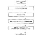
- FIG. 3 is a diagram illustrating a processing flow of the printing apparatus control unit 202.
- step S1 When the printing apparatus control unit 202 starts processing (step S1), first, storage location designation information is received from the reception unit 201 (step S2).
- step S3 the storage location indicated by the received storage location designation information is referenced. Specifically, since the storage location is in the storage medium 300, the storage location in the storage medium 300 is referred to.
- the printing apparatus control unit 202 refers to the order information associated with the image file in the storage location (step S4).
- the printing apparatus control unit 202 controls to print the image file for the number of times of printing associated with the image file in the order indicated by the order information (step S5). Specifically, in the present embodiment, the printing apparatus control unit 202 operates the tray storage container 10 and the head 40 to print an image based on the image file 1 twice (two).
- the head 40 and the like are controlled so that the image of the image file 2 is printed four times. Finally, the head 40 and the like are controlled so that the image of the image file 3 is printed eight times.
- step S6 When all the image files in the storage location are printed for the associated number of times, the process is terminated (step S6).
- the next image file may be referred to each time printing of one image file is completed in the printing order, and a RAM (so-called working memory) that temporarily stores all image files and the number of times of printing is referred to. Random Access All printing may be performed after all are stored in (Memory).
- the printing apparatus 1 drives the belt conveyor 32 to place the table 50 in the delivery area R2.
- the tray 20 is pushed out in the arrow X direction by the push-out unit 31. As a result, the tray 20 is placed on the table 50. At this time, the tray 20 moves vigorously until the tray 20 hits the pin 52 by the pushing force of the pushing portion 31. Then, by hitting the pin 52 per degree, the moving distance in the transport direction is regulated, and the position in the transport direction is adjusted.
- the position is adjusted by pressing with the acrylic plate 60.
- the table 50 is conveyed to the printing area R1.
- the position of the upper surface of the medium 100 is detected by the optical sensor 51.
- the table 50 is moved up and down for alignment.
- ink is ejected from the head 40, and the medium 100 is printed.
- the table 50 is further conveyed in the direction of the arrow X.
- post-processing such as a doming process and a spray gun process is performed as necessary.
- the printed media storage container 70 may have a mechanism such as a roller for winding the tray 20 in order to collect the tray 20.
- each block of the print control unit 200 may be realized in hardware by a logic circuit formed on an integrated circuit (IC chip), or a CPU (Central Processing Unit) may be used for software implementation.
- IC chip integrated circuit
- CPU Central Processing Unit
- the print control unit 200 includes a CPU that executes instructions of a program that realizes each function, and a ROM (Read Only Memory) that stores the program.
- a RAM Random Access Memory
- a storage device storage medium such as a memory for storing the program and various data, and the like are provided.
- An object of the present invention is a storage medium in which program codes (execution format program, intermediate code program, source program) of a control program of the print control unit 200, which is software that realizes the functions described above, are recorded so as to be readable by a computer. This can also be achieved by supplying the print control unit 200 and reading and executing the program code recorded on the storage medium by the computer (or CPU or MPU).
- Non-transitory tangible media for example, tapes such as magnetic tapes and cassette tapes, disks including magnetic disks such as floppy (registered trademark) disks / hard disks, and optical disks such as CD-ROM / MO / MD / DVD / CD-R, IC cards (including memory cards) / optical cards, semiconductor memories such as mask ROM / EPROM / EEPROM (registered trademark) / flash ROM, PLD (Programmable Logic Device), FPGA (Field Logic circuits such as Programmable Gate Array can be used.
- tapes such as magnetic tapes and cassette tapes
- optical disks such as CD-ROM / MO / MD / DVD / CD-R
- IC cards including memory cards
- semiconductor memories such as mask ROM / EPROM / EEPROM (registered trademark) / flash ROM, PLD (Programmable Logic Device), FPGA
- the print control unit 200 may be configured to be connectable to a communication network, and the program code may be supplied via the communication network.
- the communication network is not particularly limited as long as it can transmit the program code.
- the Internet intranet, extranet, LAN, ISDN, VAN, CATV communication network, virtual private network, telephone line network, mobile communication network, satellite communication network, and the like can be used.
- the transmission medium constituting the communication network may be any medium that can transmit the program code, and is not limited to a specific configuration or type.
- wired lines such as IEEE 1394, USB, power line carrier, cable TV line, telephone line, and ADSL (Asymmetric Digital Subscriber Line) line
- infrared rays such as IrDA and remote control
- Bluetooth registered trademark
- IEEE 802.11 wireless high Data Rate
- HDR High Data Rate
- NFC Near Field Communication
- DLNA Digital Living Network Alliance
- mobile phone network satellite line, terrestrial digital network, and the like.
- the present invention can also be realized in the form of a computer data signal embedded in a carrier wave in which the program code is embodied by electronic transmission.
- the print control unit 200 receives the storage location designation information that designates a storage location in which a plurality of image files indicating images to be printed are associated with the frequency information indicating the number of times of printing. And a printing device control unit 202 that controls the printing device 1 to print the image file in the storage location received by the receiving unit 201 the number of times indicated by the number of times information.
- the user only specifies the storage location, and the print control unit 200 can cause the printing apparatus 1 to perform printing based on the image file in the storage location and the number of times of printing. Therefore, even if printing is based on a plurality of image files, the printing apparatus 1 can easily recognize the target image file.
- order information indicating the printing order is associated with the image file, and the printing device control unit 202 controls the printing device 1 to perform printing according to the order information.
- the printing apparatus control unit 202 can perform printing based on the image file and the number of times along the order indicated by the order information. As a result, even if the print objects are different and image files are determined for the respective print objects, if the print objects are supplied to the printing apparatus in the order, printing is performed according to the order. Therefore, it is possible to easily perform printing on different print objects.
- the printing apparatus 1 takes out one tray 20 out of the plurality of trays 20 from the tray storage container 10 and the tray storage container 10 on which the plurality of trays 20 on which the media 100 is placed are loaded.
- a transport unit 30 that transports the ink ejecting head to the printing region R1 that faces the ink ejection surface, a printed media storage container 70 that stores the tray 20 on which the printed media 100 is placed, Is provided.
- the user simply mounts the tray 20 on the tray storage container 10 and designates the storage location of the file. Even if different types of media 100 are loaded on the tray 20, the tray 20 is stored in the printed media storage container 70. Until it is stored in the printer. That is, since the printing is repeatedly performed the number of times associated with the file, it is not necessary to manually supply the tray 20 or the medium 100 to the printing apparatus 1 each time. Therefore, long-time unattended operation is possible.
- the present invention can be used particularly suitably in the field of printing a plurality of products in large quantities, for example, smaller in size than the head.
- Printing device 10 Tray storage container (recording medium mounting part) 20 trays (mounting equipment) 30 Conveying part (conveying means) DESCRIPTION OF SYMBOLS 31 Extrusion part 32 Belt conveyor 40 Head 50 Table 51 Optical sensor 52 Pin per degree 60 Acrylic board 70 Printed media storage container (printed recording medium storage container) 100 media (recorded media) 200 Print Control Unit (Print Control Device) 201 Reception part (reception means) 202 Printing measure control unit (printing device control means) R1 Print area R2 Delivery area
Landscapes
- Engineering & Computer Science (AREA)
- Theoretical Computer Science (AREA)
- Human Computer Interaction (AREA)
- Physics & Mathematics (AREA)
- General Engineering & Computer Science (AREA)
- General Physics & Mathematics (AREA)
- Accessory Devices And Overall Control Thereof (AREA)
- Ink Jet (AREA)
- Handling Of Cut Paper (AREA)
Description
本発明は印刷制御装置に関する。
特許文献1にはプリント対象物に複数の処理作業を順に行なうための印刷装置が記載されている。
ところで、複数の画像ファイルに基づいて印刷する場合、画像ファイルを一つずつ指定して印刷を行なうことは手間である。
本発明はこのような事情に鑑みて成された発明であり、複数の画像ファイルに基づく印刷であっても容易に印刷装置に対象の画像ファイルを認識させることができる印刷制御装置を提供する。
本発明に係る印刷制御装置は、印刷する回数を示す回数情報が関連付けられた、印刷する画像を示す画像ファイルが複数格納されている格納場所を指定する格納場所指定情報を受け付ける受付手段と、上記受付手段が受け付けた格納場所の中にある上記画像ファイルを、上記回数情報が示す回数印刷するように印刷装置を制御する印刷装置制御手段とを備えることを特徴としている。
ユーザは格納場所を指定するだけで、印刷制御装置は当該格納場所内の画像ファイル及び印刷回数に基づいて印刷装置に印刷を行なわせることができる。よって、複数の画像ファイルに基づく印刷であっても容易に印刷装置に対象の画像ファイルを認識させることができる。
本発明に係る印刷制御装置では、上記画像ファイルには、印刷する順番を示す順番情報が関連付けられており、上記印刷装置制御手段は、当該順番情報に従って印刷するように印刷装置を制御するものであることがより好ましい。
印刷装置制御手段は、順番情報の示す順番に沿って、画像ファイル及び回数に基づき印刷することができる。これにより、印刷対象物が異なり、それぞれの印刷対象物に対して画像ファイルが定まっている場合であっても、順番通りに印刷対象物を印刷装置に供給すれば、当該順番に従って印刷される。よって、異なる印刷対象物に対する印刷を簡便に行なうことができる。
本発明に係る印刷装置は、本発明に係る印刷制御装置と、被記録媒体を載せた載置器具を複数搭載する被記録媒体搭載部と、上記被記録媒体搭載部から、複数の上記載置器具のうち、一つの上記載置器具を取り出し、被記録媒体に対してインクを吐出するヘッドにおけるインクを吐出する面に対向する印刷領域まで搬送させる搬送手段と、印刷された被記録媒体が載せられた載置器具を格納する印刷済被記録媒体格納器と、を備えることを特徴としている。
また、ユーザは載置器具を被記録媒体搭載部に搭載して、ファイルの格納場所を指定するだけで、載置器具毎に異なる種類の被記録媒体が載っていても、載置器具が印刷済被記録媒体格納器に格納されるまで、印刷装置の傍にいなくてもよい。つまり、ファイルに関連付けられた回数だけ繰り返し印刷が行なわれるので、都度、載置器具又は被記録媒体を印刷装置に手動で供給する必要がない。よって、長時間の無人運転が可能となる。
また、本発明に係る印刷制御装置を動作させるためのプログラムであって、コンピュータを上記の各手段として機能させるためのプログラム及び当該プログラムを記録したコンピュータ読み取り可能な記録媒体も本発明の範疇である。
本発明によれば、複数の画像ファイルに基づく印刷であっても容易に印刷装置に対象の画像ファイルを認識させることができるという効果を奏する。
〔印刷装置の構成〕
以下、本発明の実施の形態について、図1を用いて詳細に説明する。図1は本発明に係る印刷制御装置の一実施形態である印刷制御部を搭載した印刷装置の構成を模式的に示す図である。
以下、本発明の実施の形態について、図1を用いて詳細に説明する。図1は本発明に係る印刷制御装置の一実施形態である印刷制御部を搭載した印刷装置の構成を模式的に示す図である。
ここでは、本発明に係る印刷制御装置の一実施形態である印刷制御部200を搭載した印刷装置1の構成を説明する。
印刷装置1は図1に示すようにトレイ格納容器(被記録媒体搭載部)10、搬送部(搬送手段)30、ヘッド40、テーブル50、光学式センサ51、度当たりピン52、アクリル板60、印刷済メディア格納容器(印刷済被記録媒体格納器)70を備えている。
また、印刷装置1は印刷制御部(印刷制御装置)200を備えている。また、印刷制御部200は記憶媒体300と接続されている。
トレイ格納容器10は、印刷される前のメディア(被記録媒体)100が複数載せられたトレイ(載置器具)20を複数枚鉛直方向に並べて格納するためのものである。
トレイ格納容器10へのトレイ20の格納は手動で行なうが、印刷が必要なメディア100を所望の数だけトレイ20に載せ、所望の数のトレイ20をトレイ格納容器10に予め搭載しておくことができる。印刷装置1では、トレイ格納容器10から順次トレイ20を出して、ヘッド40のインク吐出面に対向する領域である印刷領域R1に搬送して印刷を行なうので、ユーザがトレイ20を印刷装置1に一枚ずつセットする必要がない。よって、長時間、ユーザが印刷装置1の傍にいなくても連続して複数のメディア100を印刷することができる。
トレイ格納容器10は、押し出し部(載置器具移動部)31を備えている。押し出し部31は搬送部30の一構成部材である。押し出し部31はトレイ20を矢印X方向に押し出す。これにより、テーブル50上にトレイ20を移動させることができる。
トレイ格納容器10は、トレイ格納容器10から取り出し移動させる対象のトレイ20が押し出し部31によって押し出される位置になるように、押し出し部31の位置を固定したまま、筐体等のその他の部材を鉛直方向に上下移動するものであってもよい。これにより、円滑に複数のトレイ20を順次テーブル50上に移動させることができる。なお、押し出し部31によってトレイ20を押し出す際に、テーブル50は矢印X方向とは逆方向に移動してトレイ20を受け取ることができる位置まで移動されて置くことが好ましい。
搬送部30は、押し出し部31及びベルトコンベア32から構成されている。
押し出し部31はトレイ格納容器10の内から矢印X方向にトレイ20を押し出すものである。
ベルトコンベア32はテーブル50を搬送するためのものである。これによりトレイ20が受け渡し領域R2から印刷済メディア格納容器70まで搬送される。なお、受け渡し領域R2において、トレイ20がテーブル50の上に載せられる。受け渡し領域R2は、押し出し部31によって押し出されたトレイ20がトレイ格納容器10から出てきたときに置かれる領域であり、テーブル50が受け渡し領域R2に位置するときにトレイ20が押し出されることによって、テーブル50の上にトレイ20が置かれる。
ベルトコンベア32は、歯付きベルトと、歯付きベルトの歯に咬合する歯車とから構成されている。このような構成によりテーブル50をより高速に搬送することができる。印刷装置1では、トレイ格納容器10から取り出されたトレイ20を印刷済メディア格納容器70まで、長距離にわたって搬送する必要があるが、このような装置に歯付きベルトを備えるベルトコンベア32を用いることによって、より短時間で搬送することができる。よって、印刷の工程全体を短時間で終了させることができる。また、歯付きであることにより位置のずれが少なく、より高精度な印刷を行なうことができる。
ヘッド40はメディア100にインクを吐出するためのものである。ヘッド40のインクを吐出する面に対向する領域、換言すれば、吐出したインクが着弾可能な領域が印刷領域R1である。ヘッド40はトレイ20上を走査するものであってもよく、トレイ20がヘッド40から吐出されたインクを受けるように適宜印刷領域R1を移動するものであってもよい。
テーブル50はトレイ20を載置するためのものである。テーブル50はベルトコンベア32上に配置されている。ベルトコンベア32の駆動に従って、矢印X方向又はその逆方向に移動する。
光学式センサ51はメディア100の上面の位置を検出するためのものである。当該位置を検出することにより、テーブル50を上下動させて印刷に適した位置にメディア100を配置することができる。
度当たりピン52は、押し出し部31によるトレイ20の搬送方向の先にあり、当該搬送方向への移動距離を規制するための位置決め部材である。押し出されたトレイ20は、度当たりピン52によって移動を停止することで矢印X方向、即ち搬送方向の位置を調節される。
アクリル板60は、メディア100の鉛直方向の位置を調整するためのものである。例えば、押し出されたトレイ20が度当たりピン52に当たるときの衝撃でメディア100が鉛直方向上向きに浮く等してずれた場合に、アクリル板60で上から押さえることによって、ずれを修正する。よって、より高精度に印刷することができる。なお、本発明に係る印刷装置における鉛直方向位置調整部は、アクリル板等の板状部材に限定されず、載置器具を鉛直方向に移動させることができるものであればよい。
アクリル板60の上下動は手動で行なってもよいが、センサ等でずれを検知した上で自動的に上下動させてもよい。上下動させる機構としては、例えば、空気圧によりアクリル板60を上下動させるシリンダが挙げられる。
また、鉛直方向の位置調整は、本発明における前処理の一態様である。本発明における前処理は位置調整に限定されるものではなく、例えば、メディアの清掃、静電気除去、プライマの塗布、表面を荒らす処理等が挙げられる。表面を荒らす処理としてはコロナ処理、例えば254nmの低波長の紫外線を照射する処理等が挙げられる。
本実施形態における前処理は受け渡し領域R2で行なう。このように前処理を受け渡し領域R2で行なうと省スペースになるため好ましいが、前処理と受け渡しとを別々の領域で行なってもよい。
印刷済メディア格納容器70は、印刷が終了したメディア100が載っているトレイ20を格納する容器である。搬送部30によって搬送されたトレイ20が順次印刷済メディア格納容器70に格納されていく。
格納されるトレイ20は図1に示すように鉛直方向に並べられる。そのため、ベルトコンベア32から搬送されるトレイ20を適切な段に格納できるように、印刷済メディア格納容器70は鉛直方向に上下動してもよい。
印刷制御部200は、印刷装置1が印刷する画像及び数(印刷の回数)を制御するものである。
印刷制御部200は、受付部(受付手段)201、印刷装置制御部(印刷装置制御手段)202を備えている。
受付部201は、印刷する回数を示す回数情報が関連付けられた、印刷する画像を示す画像ファイルが複数格納されている格納場所を指定する格納場所指定情報を受け付けるものである。
本明細書において「画像」とは、印刷によって描く図形のことを意味し、絵のみでなく、文字も包含する。
受付部201が格納場所指定情報を受け付ける方法については特に限定されない。例えば、ユーザが、マウス、キーボード、タッチパネル等の入力手段によって格納場所指定情報を入力して、受付部201が当該格納場所指定情報を受け付けてもよい。このとき、例えば、ユーザは印刷する目的の画像ファイルが格納されているフォルダ(格納場所)を指定すればよい。また、例えば、ユーザが印刷装置1にUSBメモリ等の外部記憶媒体を取り付けた際に、当該外部記憶媒体内の画像ファイルが格納されている場所を検知することによって、格納場所指定情報を認識してもよい。このような認識も格納場所指定情報の受付の一態様である。
印刷装置制御部202は、受付部201が受け付けた格納場所の中にある画像ファイルを、回数情報が示す回数印刷するように印刷装置を制御するものである。また、本実施形態では、画像ファイルに印刷する順番を示す順番情報が関連付けられているので、印刷装置制御部202は、当該順番情報に従って印刷するように印刷装置を制御するものでもある。
印刷対象物が複数種類あり、例えば、或る印刷対象物には或る画像ファイルで印刷して、別の印刷対象物には別の画像ファイルで印刷する場合においても、印刷装置に供給する印刷対象物の順番を定めておき、当該順番を示す順番情報を画像ファイルに関連付けておけば、ユーザは一度格納場所を指示するだけで、全ての印刷対象物に印刷を行なうことができる。よって、例えば、ペンケース、携帯電話のカバー等の異なる印刷対象物に対する印刷を簡便に行なうことができる。
本実施形態において、画像ファイルの格納場所は記憶媒体300に記憶されている。印刷装置制御部202は、受付部201が受け付けた格納場所指定情報に基づいて、記憶媒体300内の格納場所を参照する。
ここで、画像ファイルの格納場所内のデータ構造を図2を用いて説明する。図2は、印刷制御部202が読み取る画像データの格納場所内のデータ構造を示す図である。
図2に示すように格納場所内には複数の画像データが格納されている。図2に示す場合において3個の画像ファイルが一つのフォルダ(格納場所)の中に格納されている。それぞれの画像ファイルには印刷回数を示す回数情報及び印刷順を示す順番情報が関連付けられている。印刷装置制御部202は、当該フォルダ内の画像ファイルを読み取ることにより、各画像ファイルの印刷順及び印刷回数を認識することができる。この印刷順、印刷回数に従って画像ファイルに基づく画像を印刷するように印刷装置1のトレイ格納容器10及びヘッド40を制御する。
記憶媒体300は画像ファイルを格納するためのものである。本実施形態では記憶媒体300は印刷装置1に内装されているものとして説明をするが、外付けのものであってもよい。また、記憶媒体300はハードディスク等の磁気ディスクやCD-ROM/MO/MD/DVD/CD-R等の光ディスクを含むディスク類等で構成されていてもよい。
なお、本発明に係る印刷装置は、搬送方向における印刷領域の後、換言すれば搬送手段によって搬送する印刷領域から後の領域に被記録媒体に対して後処理を施す後処理手段を備えてもよい。後処理手段としては、オーバーコートするドーミング装置、スプレーガンが挙げられる。これにより、ドーミング工程、スプレーガン工程等を行なうことができる。
また、本発明に係る印刷装置は、差し込み作業の機能が付加されていてもよい。差し込み作業とは、載置器具を順次搬送して作業を行なう途中で、別の載置器具に対して、印刷、前処理、後処理等を行ないたい場合に当該別の載置器具を印刷装置に供することである。例えば、受け渡し領域で当該別の載置器具を載せて前処理して回収したり、そのまま印刷を行なったり、搬送方向における印刷領域の後の領域で当該別の載置器具を載せて後処理したり、差し込ませて印刷した当該別の載置器具を回収したりしてもよい。
〔印刷装置の動作〕
次に印刷装置1の動作について説明する。
次に印刷装置1の動作について説明する。
まず、メディア100をトレイ20に載せる。1枚のトレイ20に載せるメディア100の数及びトレイ20の数は目的の印刷量に応じて適宜設定すればよい。
次に、トレイ20をトレイ格納容器10に格納する。本実施形態では、図1に示すようにトレイ格納容器10内に鉛直方向に並ぶようにトレイ20を並べる。
次に、印刷装置1を稼動させる。ここで印刷制御部200の処理について説明する。
まず、ユーザは、印刷を目的とする画像ファイルの格納場所を入力する。受付部201は当該格納場所を指定する格納場所指定情報を受け付ける。
次に、受付部201は受け付けた格納場所指定情報を印刷装置制御部202に送信する。本実施形態においてユーザが指定した格納場所は図2に示す格納場所であるものとして説明する。
ここで、印刷装置制御部202の行なう処理フローについて図3を用いて説明する。図3は、印刷装置制御部202の処理フローを示す図である。
印刷装置制御部202が処理を開始すると(ステップS1)、まず、格納場所指定情報を受付部201から受信する(ステップS2)。
次に、受信した格納場所指定情報が示す格納場所を参照する(ステップS3)。具体的には格納場所は記憶媒体300内にあるので、記憶媒体300内の格納場所を参照する。
次に、印刷装置制御部202は当該格納場所内の画像ファイルに関連付けられた順番情報を参照する(ステップS4)。
次に、印刷装置制御部202は、順番情報の示す順番で、画像ファイルに関連付けられた印刷回数分当該画像ファイルを印刷するように制御する(ステップS5)。具体的には、本実施形態においては、印刷装置制御部202はトレイ格納容器10及びヘッド40を操作して、画像ファイル1に基づく画像を2回(2個)印刷する。
画像ファイル1の印刷が終わると、次は、画像ファイル2の画像を4回印刷するようにヘッド40等を制御する。最後に画像ファイル3の画像を8回印刷するようにヘッド40等を制御する。
格納場所内の画像ファイルの全てを、関連付けられた回数だけ印刷すると処理を終了する(ステップS6)。
印刷順に沿って、一つの画像ファイルの印刷が終わる毎に次の画像ファイルを参照してもよく、全ての画像ファイル及び印刷回数を参照して、一時的に記憶するいわゆるワーキングメモリとしてのRAM(Random Access
Memory)に全て記憶させておいた上で、全ての印刷を行なってもよい。
Memory)に全て記憶させておいた上で、全ての印刷を行なってもよい。
なお、以下に、印刷する画像ファイル及び回数が定まった後の、印刷装置1の印刷制御部200以外の部材の動作を説明する。
まず、印刷装置1は、ベルトコンベア32を駆動させて、テーブル50を受け渡し領域R2に配置する。
次に、押し出し部31によってトレイ20を矢印X方向に押し出す。これにより、テーブル50の上にトレイ20が載る。このとき、押し出し部31による押し出しの力によって、トレイ20が度当たりピン52に当たるまで勢いよく移動する。そして、度当たりピン52に当たることによって、搬送方向への移動距離が規制されて、当該搬送方向における位置が調整される。
次に、トレイ20が度当たりピン52に衝突することによって、トレイ20の上のメディア100が浮く等して鉛直方向にずれた場合には、アクリル板60によって押さえつけて位置を調整する。
次に、テーブル50は印刷領域R1に搬送される。印刷領域R1では、光学式センサ51によってメディア100上面の位置が検出される。検出した位置が印刷に適していない位置である場合にはテーブル50を上下動させて位置合わせが行なわれる。
次に、ヘッド40からインクが吐出されて、メディア100の印刷が行なわれる。
印刷が終了するとテーブル50はさらに矢印X方向に搬送される。搬送方向において、ヘッド40の後であって、印刷済メディア格納容器70の前の領域では、必要に応じて、ドーミング工程及びスプレーガン工程等の後処理が行なわれる。
最後に、テーブル50は印刷済メディア格納容器70の前まで搬送されて、トレイ20は印刷済メディア格納容器70に格納される。印刷済メディア格納容器70は、トレイ20を回収するためにトレイ20を巻き込むローラー等の機構を有していてもよい。
本発明は上述した各実施形態に限定されるものではなく、請求項に示した範囲で種々の変更が可能であり、異なる実施形態にそれぞれ開示された技術的手段を適宜組み合わせて得られる実施形態についても本発明の技術的範囲に含まれる。
〔ソフトウェアによる実現例〕
最後に、印刷制御部200の各ブロックは、集積回路(ICチップ)上に形成された論理回路によってハードウェア的に実現してもよいし、CPU
(Central Processing Unit)を用いてソフトウェア的に実現してもよい。
最後に、印刷制御部200の各ブロックは、集積回路(ICチップ)上に形成された論理回路によってハードウェア的に実現してもよいし、CPU
(Central Processing Unit)を用いてソフトウェア的に実現してもよい。
後者の場合、印刷制御部200は、各機能を実現するプログラムの命令を実行するCPU、上記プログラムを格納したROM(Read Only Memory)
、上記プログラムを展開するRAM(Random Access Memory)、上記プログラムおよび各種データを格納するメモリ等の記憶装置(記憶媒体)などを備えている。そして、本発明の目的は、上述した機能を実現するソフトウェアである印刷制御部200の制御プログラムのプログラムコード(実行形式プログラム、中間コードプログラム、ソースプログラム)をコンピュータで読み取り可能に記録した記憶媒体を、上記印刷制御部200に供給し、そのコンピュータ(またはCPUやMPU)が記憶媒体に記録されているプログラムコードを読み出し実行することによっても、達成可能である。
、上記プログラムを展開するRAM(Random Access Memory)、上記プログラムおよび各種データを格納するメモリ等の記憶装置(記憶媒体)などを備えている。そして、本発明の目的は、上述した機能を実現するソフトウェアである印刷制御部200の制御プログラムのプログラムコード(実行形式プログラム、中間コードプログラム、ソースプログラム)をコンピュータで読み取り可能に記録した記憶媒体を、上記印刷制御部200に供給し、そのコンピュータ(またはCPUやMPU)が記憶媒体に記録されているプログラムコードを読み出し実行することによっても、達成可能である。
上記記憶媒体としては、一時的でない有形の媒体(non-transitory
tangible medium)、例えば、磁気テープやカセットテープ等のテープ類、フロッピー(登録商標)ディスク/ハードディスク等の磁気ディスクやCD-ROM/MO/MD/DVD/CD-R等の光ディスクを含むディスク類、ICカード(メモリカードを含む)/光カード等のカード類、マスクROM/EPROM/EEPROM(登録商標)/フラッシュROM等の半導体メモリ類、あるいはPLD(Programmable logic device)やFPGA(Field
Programmable Gate Array)等の論理回路類などを用いることができる。
tangible medium)、例えば、磁気テープやカセットテープ等のテープ類、フロッピー(登録商標)ディスク/ハードディスク等の磁気ディスクやCD-ROM/MO/MD/DVD/CD-R等の光ディスクを含むディスク類、ICカード(メモリカードを含む)/光カード等のカード類、マスクROM/EPROM/EEPROM(登録商標)/フラッシュROM等の半導体メモリ類、あるいはPLD(Programmable logic device)やFPGA(Field
Programmable Gate Array)等の論理回路類などを用いることができる。
また、印刷制御部200を通信ネットワークと接続可能に構成し、上記プログラムコードを通信ネットワークを介して供給してもよい。この通信ネットワークは、プログラムコードを伝送可能であればよく、特に限定されない。例えば、インターネット、イントラネット、エキストラネット、LAN、ISDN、VAN、CATV通信網、仮想専用網(Virtual Private Network)、電話回線網、移動体通信網、衛星通信網等が利用可能である。また、この通信ネットワークを構成する伝送媒体も、プログラムコードを伝送可能な媒体であればよく、特定の構成または種類のものに限定されない。例えば、IEEE1394、USB、電力線搬送、ケーブルTV回線、電話線、ADSL(Asymmetric Digital Subscriber Line)回線等の有線でも、IrDAやリモコンのような赤外線、Bluetooth(登録商標)、IEEE802.11無線、HDR(High Data Rate)、NFC(Near Field
Communication)、DLNA(Digital Living Network Alliance)、携帯電話網、衛星回線、地上波デジタル網等の無線でも利用可能である。なお、本発明は、上記プログラムコードが電子的な伝送で具現化された、搬送波に埋め込まれたコンピュータデータ信号の形態でも実現され得る。
Communication)、DLNA(Digital Living Network Alliance)、携帯電話網、衛星回線、地上波デジタル網等の無線でも利用可能である。なお、本発明は、上記プログラムコードが電子的な伝送で具現化された、搬送波に埋め込まれたコンピュータデータ信号の形態でも実現され得る。
〔付記事項〕
以上のように、印刷制御部200は、印刷する回数を示す回数情報が関連付けられた、印刷する画像を示す画像ファイルが複数格納されている格納場所を指定する格納場所指定情報を受け付ける受付部201と、受付部201が受け付けた格納場所の中にある画像ファイルを、回数情報が示す回数印刷するように印刷装置1を制御する印刷装置制御部202とを備える。
以上のように、印刷制御部200は、印刷する回数を示す回数情報が関連付けられた、印刷する画像を示す画像ファイルが複数格納されている格納場所を指定する格納場所指定情報を受け付ける受付部201と、受付部201が受け付けた格納場所の中にある画像ファイルを、回数情報が示す回数印刷するように印刷装置1を制御する印刷装置制御部202とを備える。
ユーザは格納場所を指定するだけで、印刷制御部200は当該格納場所内の画像ファイル及び印刷回数に基づいて印刷装置1に印刷を行なわせることができる。よって、複数の画像ファイルに基づく印刷であっても容易に印刷装置1に対象の画像ファイルを認識させることができる。
印刷制御部200では、画像ファイルには、印刷する順番を示す順番情報が関連付けられており、印刷装置制御部202は、当該順番情報に従って印刷するように印刷装置1を制御するものである。
印刷装置制御部202は、順番情報の示す順番に沿って、画像ファイル及び回数に基づき印刷することができる。これにより、印刷対象物が異なり、それぞれの印刷対象物に対して画像ファイルが定まっている場合であっても、順番通りに印刷対象物を印刷装置に供給すれば、当該順番に従って印刷される。よって、異なる印刷対象物に対する印刷を簡便に行なうことができる。
印刷装置1は、印刷制御部200と、メディア100を載せたトレイ20を複数搭載するトレイ格納容器10と、トレイ格納容器10から、複数のトレイ20のうち、一つのトレイ20を取り出し、メディア100に対してインクを吐出するヘッドにおけるインクを吐出する面に対向する印刷領域R1まで搬送させる搬送部30と、印刷されたメディア100が載せられたトレイ20を格納する印刷済メディア格納容器70と、を備える。
また、ユーザはトレイ20をトレイ格納容器10に搭載して、ファイルの格納場所を指定するだけで、トレイ20毎に異なる種類のメディア100が載っていても、トレイ20が印刷済メディア格納容器70に格納されるまで、印刷装置の傍にいなくてもよい。つまり、ファイルに関連付けられた回数だけ繰り返し印刷が行なわれるので、都度、トレイ20又はメディア100を印刷装置1に手動で供給する必要がない。よって、長時間の無人運転が可能となる。
本発明は、例えばヘッドに比して大きさが小さい、複数の製品を大量に印刷する分野において特に好適に利用することができる。
1 印刷装置
10 トレイ格納容器(被記録媒体搭載部)
20 トレイ(載置器具)
30 搬送部(搬送手段)
31 押し出し部
32 ベルトコンベア
40 ヘッド
50 テーブル
51 光学式センサ
52 度当たりピン
60 アクリル板
70 印刷済メディア格納容器(印刷済被記録媒体格納器)
100 メディア(被記録媒体)
200 印刷制御部(印刷制御装置)
201 受付部(受付手段)
202 印刷措置制御部(印刷装置制御手段)
R1 印刷領域
R2 受け渡し領域
10 トレイ格納容器(被記録媒体搭載部)
20 トレイ(載置器具)
30 搬送部(搬送手段)
31 押し出し部
32 ベルトコンベア
40 ヘッド
50 テーブル
51 光学式センサ
52 度当たりピン
60 アクリル板
70 印刷済メディア格納容器(印刷済被記録媒体格納器)
100 メディア(被記録媒体)
200 印刷制御部(印刷制御装置)
201 受付部(受付手段)
202 印刷措置制御部(印刷装置制御手段)
R1 印刷領域
R2 受け渡し領域
Claims (5)
- 印刷する回数を示す回数情報が関連付けられた、印刷する画像を示す画像ファイルが複数格納されている格納場所を指定する格納場所指定情報を受け付ける受付手段と、
上記受付手段が受け付けた格納場所の中にある上記画像ファイルを、上記回数情報が示す回数印刷するように印刷装置を制御する印刷装置制御手段とを備えることを特徴とする印刷制御装置。 - 上記画像ファイルには、印刷する順番を示す順番情報が関連付けられており、
上記印刷装置制御手段は、当該順番情報に従って印刷するように印刷装置を制御するものである請求項1に記載の印刷制御装置。 - 請求項1又は2に記載の印刷制御装置と、
被記録媒体を載せた載置器具を複数搭載する被記録媒体搭載部と、
上記被記録媒体搭載部から、複数の上記載置器具のうち、一つの上記載置器具を取り出し、被記録媒体に対してインクを吐出するヘッドにおけるインクを吐出する面に対向する印刷領域まで搬送させる搬送手段と、
印刷された被記録媒体が載せられた載置器具を格納する印刷済被記録媒体格納器と、を備える印刷装置。 - 請求項1又は2に記載の印刷制御装置を動作させるためのプログラムであって、コンピュータを上記の各手段として機能させるためのプログラム。
- 請求項4に記載のプログラムを記録したコンピュータ読み取り可能な記録媒体。
Applications Claiming Priority (2)
| Application Number | Priority Date | Filing Date | Title |
|---|---|---|---|
| JP2012194606A JP6100491B2 (ja) | 2012-09-04 | 2012-09-04 | 印刷制御装置、印刷装置、プログラム及び記録媒体 |
| JP2012-194606 | 2012-09-04 |
Publications (1)
| Publication Number | Publication Date |
|---|---|
| WO2014038410A1 true WO2014038410A1 (ja) | 2014-03-13 |
Family
ID=50237023
Family Applications (1)
| Application Number | Title | Priority Date | Filing Date |
|---|---|---|---|
| PCT/JP2013/072604 Ceased WO2014038410A1 (ja) | 2012-09-04 | 2013-08-23 | 印刷制御装置、印刷装置、プログラム及び記録媒体 |
Country Status (2)
| Country | Link |
|---|---|
| JP (1) | JP6100491B2 (ja) |
| WO (1) | WO2014038410A1 (ja) |
Families Citing this family (2)
| Publication number | Priority date | Publication date | Assignee | Title |
|---|---|---|---|---|
| JP2016029224A (ja) * | 2014-07-25 | 2016-03-03 | 株式会社ミマキエンジニアリング | 染色方法、マスク形成装置、及び着色物の製造方法 |
| US10265947B2 (en) | 2016-05-31 | 2019-04-23 | Canon Kabushiki Kaisha | Control apparatus for printing apparatus, printing method, and storage medium |
Citations (4)
| Publication number | Priority date | Publication date | Assignee | Title |
|---|---|---|---|---|
| JP2001322320A (ja) * | 2000-05-15 | 2001-11-20 | Dainippon Screen Mfg Co Ltd | 印刷制御装置、印刷システム、および記録媒体 |
| JP2006150735A (ja) * | 2004-11-29 | 2006-06-15 | Casio Comput Co Ltd | 容器作成装置、容器作成システム |
| JP2007241662A (ja) * | 2006-03-08 | 2007-09-20 | King Jim Co Ltd | 小印刷物作成装置、小印刷物作成方法及び小印刷物作成プログラム |
| JP2009056655A (ja) * | 2007-08-30 | 2009-03-19 | Mimaki Engineering Co Ltd | 印刷装置 |
Family Cites Families (2)
| Publication number | Priority date | Publication date | Assignee | Title |
|---|---|---|---|---|
| JP2000278463A (ja) * | 1999-03-25 | 2000-10-06 | Canon Inc | 画像形成装置、画像形成方法および記憶媒体 |
| JP2007237710A (ja) * | 2006-03-13 | 2007-09-20 | Seiko Epson Corp | 記録装置、記録制御プログラム |
-
2012
- 2012-09-04 JP JP2012194606A patent/JP6100491B2/ja active Active
-
2013
- 2013-08-23 WO PCT/JP2013/072604 patent/WO2014038410A1/ja not_active Ceased
Patent Citations (4)
| Publication number | Priority date | Publication date | Assignee | Title |
|---|---|---|---|---|
| JP2001322320A (ja) * | 2000-05-15 | 2001-11-20 | Dainippon Screen Mfg Co Ltd | 印刷制御装置、印刷システム、および記録媒体 |
| JP2006150735A (ja) * | 2004-11-29 | 2006-06-15 | Casio Comput Co Ltd | 容器作成装置、容器作成システム |
| JP2007241662A (ja) * | 2006-03-08 | 2007-09-20 | King Jim Co Ltd | 小印刷物作成装置、小印刷物作成方法及び小印刷物作成プログラム |
| JP2009056655A (ja) * | 2007-08-30 | 2009-03-19 | Mimaki Engineering Co Ltd | 印刷装置 |
Also Published As
| Publication number | Publication date |
|---|---|
| JP2014050964A (ja) | 2014-03-20 |
| JP6100491B2 (ja) | 2017-03-22 |
Similar Documents
| Publication | Publication Date | Title |
|---|---|---|
| JP5975792B2 (ja) | 印刷装置 | |
| JP2009286128A (ja) | インクジェット印刷装置 | |
| EP2233303A3 (en) | Printing apparatus | |
| JP6100491B2 (ja) | 印刷制御装置、印刷装置、プログラム及び記録媒体 | |
| JP6033009B2 (ja) | 格納制御装置、印刷装置、プログラム及び記録媒体 | |
| US9128651B2 (en) | Printing apparatus, method of controlling printing apparatus, and storage medium | |
| US20150273901A1 (en) | Printer system, inkjet printer, and computer-readable recording medium containing program therefor | |
| CN107116900B (zh) | 印刷装置以及印刷方法 | |
| CN102815097A (zh) | 控制方法、控制装置及加工装置 | |
| JP5708205B2 (ja) | 操作情報提供システム、携帯端末及び制御プログラム | |
| EP2763025A1 (en) | Method and device for controlling pause in printing | |
| CN108349245B (zh) | 喷墨记录装置 | |
| US10325187B2 (en) | Mobile printer | |
| KR101943444B1 (ko) | 영상 처리를 통한 코팅장치 및 코팅방법 | |
| JP6820674B2 (ja) | 記録装置および記録方法 | |
| CN103092535B (zh) | 一种打印控制方法及装置 | |
| JP5994468B2 (ja) | 印刷装置 | |
| JP2013180897A (ja) | カード積載移送装置及びカードプリンタ | |
| JP2013159079A (ja) | カッティング装置、カッティング方法及びプログラム | |
| JP2018144263A (ja) | 記録装置および記録方法 | |
| JP2018008797A (ja) | 搬送検出装置、搬送装置、記録装置、搬送検出方法およびプログラム | |
| JP2009208380A5 (ja) | ||
| JP2013254452A (ja) | 情報記録装置及びリライタブルプリンタ | |
| JP2011224863A (ja) | 製膜装置および製膜方法 | |
| JP2011056680A (ja) | 画像記録装置、及び画像記録装置の制御方法 |
Legal Events
| Date | Code | Title | Description |
|---|---|---|---|
| 121 | Ep: the epo has been informed by wipo that ep was designated in this application |
Ref document number: 13836182 Country of ref document: EP Kind code of ref document: A1 |
|
| NENP | Non-entry into the national phase |
Ref country code: DE |
|
| 122 | Ep: pct application non-entry in european phase |
Ref document number: 13836182 Country of ref document: EP Kind code of ref document: A1 |