WO2014037990A1 - アオコ発生抑止装置 - Google Patents
アオコ発生抑止装置 Download PDFInfo
- Publication number
- WO2014037990A1 WO2014037990A1 PCT/JP2012/072461 JP2012072461W WO2014037990A1 WO 2014037990 A1 WO2014037990 A1 WO 2014037990A1 JP 2012072461 W JP2012072461 W JP 2012072461W WO 2014037990 A1 WO2014037990 A1 WO 2014037990A1
- Authority
- WO
- WIPO (PCT)
- Prior art keywords
- water
- conduit
- lake
- occurrence
- generation
- Prior art date
- Legal status (The legal status is an assumption and is not a legal conclusion. Google has not performed a legal analysis and makes no representation as to the accuracy of the status listed.)
- Ceased
Links
Images


Classifications
-
- C—CHEMISTRY; METALLURGY
- C02—TREATMENT OF WATER, WASTE WATER, SEWAGE, OR SLUDGE
- C02F—TREATMENT OF WATER, WASTE WATER, SEWAGE, OR SLUDGE
- C02F3/00—Biological treatment of water, waste water, or sewage
- C02F3/02—Aerobic processes
- C02F3/12—Activated sludge processes
- C02F3/14—Activated sludge processes using surface aeration
-
- C—CHEMISTRY; METALLURGY
- C02—TREATMENT OF WATER, WASTE WATER, SEWAGE, OR SLUDGE
- C02F—TREATMENT OF WATER, WASTE WATER, SEWAGE, OR SLUDGE
- C02F3/00—Biological treatment of water, waste water, or sewage
- C02F3/02—Aerobic processes
- C02F3/12—Activated sludge processes
- C02F3/22—Activated sludge processes using circulation pipes
-
- C—CHEMISTRY; METALLURGY
- C02—TREATMENT OF WATER, WASTE WATER, SEWAGE, OR SLUDGE
- C02F—TREATMENT OF WATER, WASTE WATER, SEWAGE, OR SLUDGE
- C02F2103/00—Nature of the water, waste water, sewage or sludge to be treated
- C02F2103/007—Contaminated open waterways, rivers, lakes or ponds
-
- C—CHEMISTRY; METALLURGY
- C02—TREATMENT OF WATER, WASTE WATER, SEWAGE, OR SLUDGE
- C02F—TREATMENT OF WATER, WASTE WATER, SEWAGE, OR SLUDGE
- C02F2303/00—Specific treatment goals
- C02F2303/20—Prevention of biofouling
-
- C—CHEMISTRY; METALLURGY
- C02—TREATMENT OF WATER, WASTE WATER, SEWAGE, OR SLUDGE
- C02F—TREATMENT OF WATER, WASTE WATER, SEWAGE, OR SLUDGE
- C02F3/00—Biological treatment of water, waste water, or sewage
- C02F3/02—Aerobic processes
- C02F3/12—Activated sludge processes
- C02F3/24—Activated sludge processes using free-fall aeration or spraying
-
- C—CHEMISTRY; METALLURGY
- C02—TREATMENT OF WATER, WASTE WATER, SEWAGE, OR SLUDGE
- C02F—TREATMENT OF WATER, WASTE WATER, SEWAGE, OR SLUDGE
- C02F3/00—Biological treatment of water, waste water, or sewage
- C02F3/32—Biological treatment of water, waste water, or sewage characterised by the animals or plants used, e.g. algae
- C02F3/322—Biological treatment of water, waste water, or sewage characterised by the animals or plants used, e.g. algae use of algae
-
- Y—GENERAL TAGGING OF NEW TECHNOLOGICAL DEVELOPMENTS; GENERAL TAGGING OF CROSS-SECTIONAL TECHNOLOGIES SPANNING OVER SEVERAL SECTIONS OF THE IPC; TECHNICAL SUBJECTS COVERED BY FORMER USPC CROSS-REFERENCE ART COLLECTIONS [XRACs] AND DIGESTS
- Y02—TECHNOLOGIES OR APPLICATIONS FOR MITIGATION OR ADAPTATION AGAINST CLIMATE CHANGE
- Y02W—CLIMATE CHANGE MITIGATION TECHNOLOGIES RELATED TO WASTEWATER TREATMENT OR WASTE MANAGEMENT
- Y02W10/00—Technologies for wastewater treatment
- Y02W10/10—Biological treatment of water, waste water, or sewage
Definitions
- the present invention relates to a sea cucumber generation suppression device.
- Blue sea lions are mainly floating cyanobacteria, but also contain green algae and the like, and are composed of particulate alga bodies. These particulate alga bodies drift and cover the water surface, and the occurrence of blue sea bream leads to deterioration of water quality due to light shielding and lack of oxygen.
- the prevention device disclosed in Patent Document 1 prevents the occurrence of aquatic by shielding the water surface with a light shielding material. Furthermore, the prevention device mounts a solar panel on the surface of the light shielding material, and transmits electric energy to a required location.
- the device disclosed in Patent Document 2 floats a light shielding material with a solar panel on the surface of a lake or the like, and provides a water conduit underneath, and pushes surface water into the deep part of the lake through the water conduit.
- water is fluidized and circulated to suppress the occurrence of blue sea bream.
- the present invention has an object of providing a water-bloom generation inhibiting device that efficiently inhibits the occurrence of water-bloom in lakes and the like.
- a blue-flooding deterrent device that suppresses the occurrence of blue-green algae in a lake, and is below the surface layer heated by sunlight among the main body part floating on the water surface of the lake and the water temperature layer constituting the lake.
- a water conduit that reaches a lower layer whose water temperature is lower than the surface layer, a water intake portion that is provided in the main body and takes water in the lower layer through the water conduit, and the water taken in by the water intake portion
- a water-bloom generation suppressing device comprising: an injection unit that injects lower layer water onto the water surface.
- the sea cucumber generation suppression device floats on the surface of the lake.
- production suppression apparatus takes water through a water conduit from the lower layer whose water temperature is lower than a surface layer, and injects the water of the taken lower layer on the water surface.
- the apparatus for suppressing the occurrence of aquatic plants according to the present invention floats on the surface of the lake and shields it from light, and sprays low-temperature water taken from the lake onto the surface of the water, thereby lowering the temperature of the surface layer where the mushroom is generated and Shock and kill. Therefore, the water-bloom generation inhibiting device according to the present invention can efficiently inhibit the occurrence of water-bloom in lakes and the like.
- the water pipe has a water intake hole for water intake on a side surface of the water pipe which is closed at a predetermined distance along the pipe from the front end, and has a water intake hole. .
- the tip of the conduit may come into contact with the bottom of the lake when the water level in the lake falls.
- the water guide pipe sucks dust or the like, or makes it difficult to suck water. Therefore, when the water-blowing generation suppressing device takes water through the water conduit, water is taken from the side water intake hole instead of the tip portion. Therefore, the water-bloom generation inhibiting device can take water even when the water level falls and the tip of the water guide tube contacts the bottom of the water, so that the occurrence of water-bloom in a lake or the like can be more efficiently inhibited.
- the water-bloom generation suppressing device expands and contracts the length of the water conduit, takes water from a lower layer having a low water temperature, and jets the taken lower layer water to the water surface. Therefore, the sea cucumber generation suppression device can more efficiently suppress the generation of sea cucumbers in lakes and the like.
- the main body part further includes a photovoltaic power generation panel, and the water intake part is operated by electricity generated by the photovoltaic power generation panel, and the occurrence of water-bloom according to any one of (1) to (3) Suppressor.
- the water-bloom generation suppressing device takes in low-temperature water from the lower layer with electricity generated by the solar power generation panel of the device itself, and jets the taken water onto the water surface. Therefore, the water-bloom generation inhibiting device can be arranged at a position where water-flooding is likely to occur on the water surface of the lake without being affected by the relationship with the power source. Therefore, the sea cucumber generation suppression device can more efficiently suppress the generation of sea cucumbers in lakes and the like.
- the present invention it is possible to efficiently suppress the occurrence of aquatic plants in lakes and the like due to the lowering of the surface water temperature by spraying low temperature water, the effect of destroying the cells of the green plant, and light shielding.
- FIG. 1 It is a block diagram which shows the dwarf generation suppression apparatus which concerns on Embodiment 1 of this invention. It is a figure which shows the example of the water conduit of the water-bloom generation
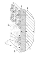
- FIG. 1 is a block diagram showing a dwarf generation inhibiting apparatus 10 according to Embodiment 1 of the present invention.
- the water-bloom generation suppressing device 10 includes a main body part 11, a water conduit 12, a water intake part 13, and an injection part 14.
- the main body 11 floats on the water surface 300 of the lake. Lakes refer to lakes, swamps, reservoirs, dam lakes, etc.
- the main body 11 may be lifted from the water surface 300 by a float or the like.
- the water surface 300 under the main body part 11 is shielded by the main body part 11 so that no mushroom 301 is generated.
- the water guide pipe 12 is a pipe that reaches a lower layer 203 below the surface layer 201 that is warmed by sunlight and whose water temperature is lower than the surface layer 201 among the water temperature layers that constitute the lake.
- the temperature layer of water constituting the lake includes, for example, a surface layer 201 (also referred to as a surface water layer) heated by sunlight, a lower temperature layer 203 (also referred to as a lowermost layer or a deep water layer), and a surface layer 201.
- the intermediate layer 202 also referred to as a water temperature jump layer having a large temperature change
- the length of the water conduit 12 is preferably about 5 m below the water surface.
- the water guide pipe 12 is configured to allow water to flow into the main body 11 from underwater, and may be made of a material whose outer side is hard to some extent, for example, a pipe. Further, the water conduit 12 may be made of a material whose outer side is soft to some extent, for example, a hose so that the tip portion may reach the bottom of the water when the water level drops. Water flows from a water intake hole provided in the water conduit 12 (for example, a water intake hole provided at the tip or a water intake hole provided on the side surface).
- the water intake unit 13 is provided in the main body unit 11 and takes in water of the lower layer 203 through the water conduit 12. Specifically, the water intake unit 13 is configured by a pump. The pump sucks up the water in the lower layer 203 through the water conduit 12 and discharges the sucked up water to the injection unit 14.
- the jetting unit 14 jets the water of the lower layer 203 taken by the water taking unit 13 onto the water surface 300.
- the injection unit 14 is configured by a nozzle.
- the nozzle sprays the water discharged by the water intake unit 13 onto the water surface 300.
- the jetted water lowers the water temperature of the surface layer 201 and can also kill and kill the cells of the sea bream 301 by water pressure.
- the injection unit 14 may be configured by a nozzle directed from the water intake unit 13 into the air.
- the nozzle directed into the air causes water to be ejected like a fountain and drops onto the water surface 300.
- the water falling on the water surface 300 lowers the water temperature of the surface layer 201 and gives an impact to the cells of the blue sea bream 301.
- the injection unit 14 may be configured by a nozzle directed from the water intake unit 13 to the water surface 300.
- a plurality of nozzles directed to the water surface 300 are installed along the edge of the main body 11, and the plurality of installed nozzles directly jet water toward the water surface 300.
- the jetted water lowers the water temperature of the surface layer 201 and gives an impact to the cells of the blue sea 301.
- the injection unit 14 may be configured by a nozzle directed from the water intake unit 13 into the water.
- a plurality of nozzles that are directed from the water toward the water surface 300 are directed toward the water surface 300 along the underwater edge of the main body unit 11, and the plurality of nozzles that are installed allow water to flow from the water toward the water surface 300.
- the jetted water lowers the water temperature of the surface layer 201 and gives an impact to the cells of the sea bream 301 while passing through the water.
- the sea cucumber generation suppression device 10 floats on the water surface 300 of the lake and is a layer below the surface layer 201 heated by sunlight among the water temperature layers constituting the lake.
- Water in the lower layer 203 is taken in through the water conduit 12 reaching the lower layer 203 lower than the surface layer 201, and the water in the lower layer 203 that has been taken in is sprayed onto the water surface 300. Therefore, the water-bloom generation inhibiting device 10 can efficiently inhibit the occurrence of the water-bloom 301 in a lake or the like.
- FIG. 2 is a diagram illustrating an example of the water conduit 12 of the sea cucumber generation suppression device 10 according to the second embodiment of the present invention.
- the extendable mechanism of the water conduit 12 is a double coaxial structure of a first water conduit 121 and a second water conduit 122 having a larger diameter than the first water conduit 121.
- the first water conduit 121 is provided with a stopper 1231
- the second water conduit 122 is provided with a stopper 1232.
- the second water guide pipe 122 slides to the stoppers 1231 and 1232 by its own weight in the vertically downward direction, and slides in the vertically upward direction when receiving a force in the vertically upward direction (for example, the front end portion 124 reaches the water bottom).
- the second water conduit 122 moves and extends to the longest length of the water conduit 12 to reach the lower layer, and the water depth is the water conduit.
- the second water conduit 122 moves and contracts to the length of the water bottom.
- the positions of the stoppers 1231 and 1232 (for example, the position where the lengths of the first water conduit 121 and the second water conduit 122 are combined to be about 5 m at the longest) may be variable. , It may be changed according to the fluctuation of the water level.
- the extendable mechanism of the water conduit 12 may be configured in a double or more cylindrical shape, and the portion excluding the water intake hole 131 may have a bellows structure and can be expanded and contracted.
- the water guide pipe 12 is provided with a water intake hole 131 for water intake on the side surface, which is closed by a predetermined distance 132 (for example, 10 to 20 cm) along the pipe from the front end part 124 with the front end part 124 of the pipe closed.
- the water-bloom generation inhibiting device 10 takes water from a position where it is difficult to suck in foreign matter such as dust even if the tip 124 contacts the bottom of the water by taking water from the water intake hole 131 on the side surface of the water conduit 12.
- the second conduit 122 is larger in diameter than the first conduit 121, the foreign matter that has entered the first conduit 121 is smaller than the first conduit 121, as in the case where the second conduit 122 is smaller in diameter than the first conduit 121. There is no precipitation between the first water conduit 121 and the second water conduit 122.
- maintains the water which the water intake part 13 pumped up temporarily, and the water which hold
- the water-bloom generation suppressing device 10 can eliminate clogging of the water intake hole 131 due to dust by periodic backflow.
- the water-blowing generation suppressing device 10 takes water from the water intake hole 131 on the side surface where the length of the water guide pipe 12 expands and contracts, and when the water guide pipe 12 reaches the bottom of the water, it is difficult to suck dust and the like.
- the water taken is sprayed onto the water surface 300. Therefore, the water-bloom generation inhibiting device 10 can efficiently inhibit the occurrence of the water-bloom 301 in a lake or the like.
- the sea cucumber generation suppression device 10 includes a photovoltaic power generation panel 102 and operates by electricity generated by the photovoltaic power generation panel 102.
- FIG. 3 is a diagram illustrating a case where the aquatic generation inhibiting device 10 according to Embodiment 3 of the present invention is installed on a water surface 300 such as a lake.
- the sea cucumber generation suppression device 10 operates by electricity generated by the photovoltaic power generation panel 102 provided in the main body 11.
- the photovoltaic power generation panel 102 installed in one unit for preventing the occurrence of sea cucumber 10 has a size that can cover the power of the pump 101 constituting the water intake unit 13.
- the connected aquatic occurrence inhibiting devices 10 maximize the effects of injection and light shielding. You can make use of it.
- the connected sea cucumber generation suppression device 10 is installed in a flexible manner corresponding to the shape of a lake or the like, depending on how the chain 103 is connected. Further, the connected sea cucumber generation suppression device 10 can be installed correspondingly by changing the position and interval of each other according to the change in the area of the water surface 300 due to a sudden water level fluctuation such as a dam lake. Since repair and replacement are possible for each of the connected blue-floor generation inhibiting devices 10, the maintainability is also high.
- the sea cucumber generation suppression device 10 further includes a photovoltaic power generation panel 102, and a plurality of sea cucumber generation suppression devices 10 are connected by a chain without being affected by the relationship with the power source.
- production suppression apparatus 10 prevents the sunlight from hitting the water surface 300 by the main-body part 11, and injects the low temperature water of a lower layer to the water surface 300.
- FIG. Therefore, the water-bloom generation suppressing device 10 is arranged in a lake or the like in which a plurality of water-blowing generation suppression devices 10 including the photovoltaic power generation panel 102 are connected by a chain, and is shielded in the lake and the like by shading and low-temperature water injection. It is possible to more efficiently suppress the occurrence of the blue sea bream 301.
Landscapes
- Life Sciences & Earth Sciences (AREA)
- Biodiversity & Conservation Biology (AREA)
- Microbiology (AREA)
- Hydrology & Water Resources (AREA)
- Engineering & Computer Science (AREA)
- Environmental & Geological Engineering (AREA)
- Water Supply & Treatment (AREA)
- Chemical & Material Sciences (AREA)
- Organic Chemistry (AREA)
- Aeration Devices For Treatment Of Activated Polluted Sludge (AREA)
- Catching Or Destruction (AREA)
Description
本発明は、アオコ発生抑止装置に関する。
従来より、富栄養化が進んだ湖沼等には、アオコが発生することが知られている。アオコは、主に浮遊性藍藻であるが、緑藻等をも含み、粒子状の藻体からなる。これらの粒子状の藻体が漂って水面を覆い、アオコの発生は、遮光や酸欠による水質の悪化を招く。
アオコは植物プランクトンであるため、その発生の原因は、栄養塩と水温と日光とにある。このため、アオコを除去する方法として、(1)栄養塩を取除く、(2)水温を下げる、(3)太陽光を遮蔽する等の方法がある。
例えば、特許文献1に開示された防止装置は、遮光材で水面を遮光することにより、アオコの発生を防止する。さらに、防止装置は、遮光材の表面に太陽光パネルを搭載し、電気エネルギーを所要箇所に送電する。
また、特許文献2に開示された装置は、湖沼等の水面に太陽光パネルを搭載した遮光材を浮かべ、その下側に導水管を設け、導水管を通して表層水を湖沼の深部へ押込むことにより、水を流動循環させて、アオコの発生を抑制する。
しかしながら、特許文献1に開示された技術のように、遮光部材でアオコ等を死滅させるためには、遮光面積を大きくする必要があり、遮光面積が大き過ぎると、藻類が全て死滅して生態系が崩れるというおそれがある。また、特許文献2に開示された技術のように、表層の暖かい水を深部へ押込むだけでは、アオコが死滅する事なく再び浮上するおそれがある。
そこで、湖沼等におけるアオコの発生を効率よく抑止する装置が求められている。
本発明は、湖沼等におけるアオコの発生を効率よく抑止するアオコ発生抑止装置を提供することを目的とする。
本発明では、以下のような解決手段を提供する。
(1) 湖沼におけるアオコの発生を抑止するアオコ発生抑止装置であって、前記湖沼の水面に浮かぶ本体部と、前記湖沼を構成する水の温度の層のうち、太陽光で温められる表層より下の層であって水温が前記表層より低い下層に達する導水管と、前記本体部に設けられ、前記導水管を介して前記下層の水を取水する取水部と、前記取水部によって取水された前記下層の水を水面に噴射する噴射部と、を備えるアオコ発生抑止装置。
(1) 湖沼におけるアオコの発生を抑止するアオコ発生抑止装置であって、前記湖沼の水面に浮かぶ本体部と、前記湖沼を構成する水の温度の層のうち、太陽光で温められる表層より下の層であって水温が前記表層より低い下層に達する導水管と、前記本体部に設けられ、前記導水管を介して前記下層の水を取水する取水部と、前記取水部によって取水された前記下層の水を水面に噴射する噴射部と、を備えるアオコ発生抑止装置。
(1)の構成によれば、本発明に係るアオコ発生抑止装置は、湖沼の水面に浮かぶ。そして、アオコ発生抑止装置は、水温が表層より低い下層から導水管を介して取水し、取水した下層の水を水面に噴射する。
すなわち、本発明に係るアオコ発生抑止装置は、湖沼の水面に浮かんで遮光し、湖沼から取水した低温の水を水面に噴射することにより、アオコが発生する表層の温度を下げると共に、アオコの細胞に衝撃を与え死滅させる。
したがって、本発明に係るアオコ発生抑止装置は、湖沼等におけるアオコの発生を効率よく抑止することができる。
したがって、本発明に係るアオコ発生抑止装置は、湖沼等におけるアオコの発生を効率よく抑止することができる。
(2) 前記導水管は、管の先端部が閉じられ、前記先端部から管に沿って所定距離だけ離れた側面に取水のための取水穴を備える、(1)に記載のアオコ発生抑止装置。
導水管の先端部は、湖沼の水位が下がると水底に接触する場合がある。先端部が水底に接触すると、導水管は、ごみ等を吸い込んだり、水を吸い込みにくくなったりする。そこで、アオコ発生抑止装置は、導水管を介して取水する際に、先端部ではなく、側面の取水穴から取水する。
したがって、アオコ発生抑止装置は、水位が下がり導水管の先端部が水底に接触しても取水することができるので、湖沼等におけるアオコの発生をさらに効率よく抑止することができる。
したがって、アオコ発生抑止装置は、水位が下がり導水管の先端部が水底に接触しても取水することができるので、湖沼等におけるアオコの発生をさらに効率よく抑止することができる。
(3) 前記導水管は、管の長さが伸縮する伸縮可能機構を有する、(1)又は(2)に記載のアオコ発生抑止装置。
すなわち、アオコ発生抑止装置は、導水管の管の長さを伸縮させて、水温が低い下層から取水し、取水した下層の水を水面に噴射する。
したがって、アオコ発生抑止装置は、湖沼等におけるアオコの発生をさらに効率よく抑止することができる。
したがって、アオコ発生抑止装置は、湖沼等におけるアオコの発生をさらに効率よく抑止することができる。
(4) 前記本体部は、太陽光発電パネルをさらに備え、前記取水部は、前記太陽光発電パネルによって発電された電気により動作する、(1)から(3)のいずれかに記載のアオコ発生抑止装置。
すなわち、アオコ発生抑止装置は、装置自身の太陽光発電パネルによって発電された電気により、下層から低温の水を取水し、取水した水を水面に噴射する。よって、アオコ発生抑止装置は、動力源との関係に影響されずに、湖沼の水面のうちアオコが発生しそうな位置に配置されることができる。
したがって、アオコ発生抑止装置は、湖沼等におけるアオコの発生をさらに効率よく抑止することができる。
したがって、アオコ発生抑止装置は、湖沼等におけるアオコの発生をさらに効率よく抑止することができる。
本発明によれば、低温の水を噴射することによる表層の水温の低下及びアオコの細胞の破壊効果と、遮光とにより、湖沼等におけるアオコの発生を効率よく抑止することができる。
[実施形態1]
以下、本発明の実施形態について図を参照しながら説明する。図1は、本発明の実施形態1に係るアオコ発生抑止装置10を示すブロック図である。
アオコ発生抑止装置10は、本体部11と、導水管12と、取水部13と、噴射部14とを備える。
以下、本発明の実施形態について図を参照しながら説明する。図1は、本発明の実施形態1に係るアオコ発生抑止装置10を示すブロック図である。
アオコ発生抑止装置10は、本体部11と、導水管12と、取水部13と、噴射部14とを備える。
本体部11は、湖沼の水面300に浮かぶ。湖沼とは、湖、沼、貯水池、ダム湖等をいう。
本体部11は、フロート等により水面300から浮き上がっていてもよい。本体部11の下の水面300は、本体部11により遮光されてアオコ301が発生せず、既に発生しているアオコ301は、遮光されて光合成ができないため死滅する。
本体部11は、フロート等により水面300から浮き上がっていてもよい。本体部11の下の水面300は、本体部11により遮光されてアオコ301が発生せず、既に発生しているアオコ301は、遮光されて光合成ができないため死滅する。
導水管12は、湖沼を構成する水の温度の層のうち、太陽光で温められる表層201より下の層であって水温が表層201より低い下層203に達する管である。
湖沼を構成する水の温度の層は、例えば、太陽光によって温められる表層201(表水層とも言われる)と、温度の低い下層203(最下層や、深水層とも言われる)と、表層201と下層203との間の中間層202(温度変化の大きい水温躍層とも言われる)との3層を構成するものが多い。
また、例えば、ダム湖等では、過去の測定結果から水深5mより深部の水温分布には大きな変化が無い。そこで、導水管12の長さは、水面下略5mが望ましい。
湖沼を構成する水の温度の層は、例えば、太陽光によって温められる表層201(表水層とも言われる)と、温度の低い下層203(最下層や、深水層とも言われる)と、表層201と下層203との間の中間層202(温度変化の大きい水温躍層とも言われる)との3層を構成するものが多い。
また、例えば、ダム湖等では、過去の測定結果から水深5mより深部の水温分布には大きな変化が無い。そこで、導水管12の長さは、水面下略5mが望ましい。
導水管12は、水中から本体部11に水を流入させるように構成され、外側がある程度硬い素材で製造されているもの、例えば、パイプのようなものであってよい。また、導水管12は、水位が下がった場合に先端部が水底に到達してもいいように外側がある程度柔らかい素材で製造されているもの、例えば、ホースのようなものであってもよい。
水は、導水管12に設けられた取水穴(例えば、先端に設けられた取水穴や側面に設けられた取水穴等)から流入する。
水は、導水管12に設けられた取水穴(例えば、先端に設けられた取水穴や側面に設けられた取水穴等)から流入する。
取水部13は、本体部11に設けられ、導水管12を介して下層203の水を取水する。具体的には、取水部13は、ポンプにより構成される。ポンプは、導水管12を介して下層203の水を吸い上げ、吸い上げた水を噴射部14まで吐出する。
噴射部14は、取水部13によって取水された下層203の水を水面300に噴射する。具体的には、噴射部14は、ノズルにより構成される。ノズルは、取水部13によって吐出された水を、水面300に噴射する。噴射された水は、表層201の水温を下げると共に、水圧によってアオコ301の細胞に衝撃を与え死滅させることができる。
例えば、噴射部14は、取水部13から空中に向けられたノズルによって構成されるとしてもよい。空中に向けられたノズルは、噴水のように水を噴出させ、水面300に落下させる。水面300に落下した水は、表層201の水温を下げると共に、アオコ301の細胞に衝撃を与える。
例えば、噴射部14は、取水部13から空中に向けられたノズルによって構成されるとしてもよい。空中に向けられたノズルは、噴水のように水を噴出させ、水面300に落下させる。水面300に落下した水は、表層201の水温を下げると共に、アオコ301の細胞に衝撃を与える。
噴射部14は、取水部13から水面300に向けられたノズルによって構成されるとしてもよい。例えば、水面300に向けられたノズルは、本体部11の縁に沿って複数設置され、設置された複数のノズルは、水面300に向かって水を直接的に噴射する。噴射された水は、表層201の水温を下げると共に、アオコ301の細胞に衝撃を与える。
噴射部14は、取水部13から水中に向けられたノズルによって構成されるとしてもよい。例えば、水中から水面300に向けられたノズルは、本体部11の水中の縁に沿って水面300に向けられて複数設置され、設置された複数のノズルは、水中から水面300に向かって水を噴射する。噴射された水は、表層201の水温を下げると共に、水中を通過しながらアオコ301の細胞に衝撃を与える。
本実施形態1によれば、アオコ発生抑止装置10は、湖沼の水面300に浮かび、湖沼を構成する水の温度の層のうち、太陽光で温められる表層201より下の層であって水温が表層201より低い下層203に達する導水管12を介して下層203の水を取水し、取水した下層203の水を水面300に噴射する。したがって、アオコ発生抑止装置10は、湖沼等におけるアオコ301の発生を効率よく抑止することができる。
[実施形態2]
実施形態2におけるアオコ発生抑止装置10は、実施形態1の構成に加えて、導水管12の管の長さが伸縮する伸縮可能機構を有する。
図2は、本発明の実施形態2に係るアオコ発生抑止装置10の導水管12の例を示す図である。
実施形態2におけるアオコ発生抑止装置10は、実施形態1の構成に加えて、導水管12の管の長さが伸縮する伸縮可能機構を有する。
図2は、本発明の実施形態2に係るアオコ発生抑止装置10の導水管12の例を示す図である。
具体的には、導水管12の伸縮可能機構は、図2に示すように、第1導水管121と、第1導水管121よりも大径の第2導水管122との2重の同軸の筒状に構成され、第1導水管121にストッパー1231と、第2導水管122にストッパー1232とがそれぞれ設けられている。第2導水管122は、鉛直下方向に自己の重さによりストッパー1231、1232までスライドし、鉛直上方向に力を受ける(例えば、先端部124が水底に達する)と鉛直上方向にスライドする。
例えば、導水管12の長さは、水深が導水管12の長さより深い場合は、第2導水管122が移動して導水管12の最長の長さまで伸びて下層に到達し、水深が導水管12の長さより浅い場合は、第2導水管122が移動して水底までの長さに縮む。
ストッパー1231、1232の位置(例えば、第1導水管121と第2導水管122との長さを合わせて最長略5mになるような位置)は、可変であってもよく、湖沼等の水深や、水位の変動に応じて変えられるようになっていてもよい。
また、導水管12の伸縮可能機構は、2重以上の筒状に構成されていてもよく、取水穴131を除いた部分が蛇腹構造になっていて伸び縮みできるとしてもよい。
例えば、導水管12の長さは、水深が導水管12の長さより深い場合は、第2導水管122が移動して導水管12の最長の長さまで伸びて下層に到達し、水深が導水管12の長さより浅い場合は、第2導水管122が移動して水底までの長さに縮む。
ストッパー1231、1232の位置(例えば、第1導水管121と第2導水管122との長さを合わせて最長略5mになるような位置)は、可変であってもよく、湖沼等の水深や、水位の変動に応じて変えられるようになっていてもよい。
また、導水管12の伸縮可能機構は、2重以上の筒状に構成されていてもよく、取水穴131を除いた部分が蛇腹構造になっていて伸び縮みできるとしてもよい。
導水管12は、管の先端部124が閉じられ、先端部124から管に沿って所定距離132(例えば、10~20cm)だけ離れた側面に取水のための取水穴131を備える。
アオコ発生抑止装置10は、導水管12の側面の取水穴131から取水することにより、先端部124が水底に接触してもゴミ等の異物を吸い込みにくい位置から取水する。さらに、第2導水管122は、第1導水管121よりも大径なので、第2導水管122が第1導水管121よりも小径の場合のように、第1導水管121に入り込んだ異物が第1導水管121と第2導水管122との間に沈殿することもない。
アオコ発生抑止装置10は、導水管12の側面の取水穴131から取水することにより、先端部124が水底に接触してもゴミ等の異物を吸い込みにくい位置から取水する。さらに、第2導水管122は、第1導水管121よりも大径なので、第2導水管122が第1導水管121よりも小径の場合のように、第1導水管121に入り込んだ異物が第1導水管121と第2導水管122との間に沈殿することもない。
なお、アオコ発生抑止装置10は、取水部13が汲み上げた水を一時的に保留し、保留した水を導水管12から下層203へ、定期的(例えば、日中12時から10分等)に逆流させるとしてもよい。アオコ発生抑止装置10は、定期的な逆流によって、ゴミによる取水穴131の目詰まりを解消できる。
本実施形態2によれば、アオコ発生抑止装置10は、導水管12の管の長さが伸縮し、導水管12が水底に達した場合にごみ等を吸い込みにくい側面の取水穴131から取水し、取水した水を水面300に噴射する。したがって、アオコ発生抑止装置10は、湖沼等におけるアオコ301の発生を効率よく抑止することができる。
[実施形態3]
実施形態3におけるアオコ発生抑止装置10は、実施形態1及び2に加えて、太陽光発電パネル102を備え、太陽光発電パネル102によって発電された電気により動作する。図3は、本発明の実施形態3に係るアオコ発生抑止装置10を湖沼等の水面300に設置した場合を示す図である。アオコ発生抑止装置10は、本体部11に設けられた太陽光発電パネル102によって発電された電気により動作する。例えば、1台のアオコ発生抑止装置10に設置された太陽光発電パネル102は、取水部13を構成するポンプ101の動力を賄える大きさとする。
実施形態3におけるアオコ発生抑止装置10は、実施形態1及び2に加えて、太陽光発電パネル102を備え、太陽光発電パネル102によって発電された電気により動作する。図3は、本発明の実施形態3に係るアオコ発生抑止装置10を湖沼等の水面300に設置した場合を示す図である。アオコ発生抑止装置10は、本体部11に設けられた太陽光発電パネル102によって発電された電気により動作する。例えば、1台のアオコ発生抑止装置10に設置された太陽光発電パネル102は、取水部13を構成するポンプ101の動力を賄える大きさとする。
図3に示すように、アオコ発生抑止装置10を複数台使用し、アオコ発生抑止装置10同士をチェーン103等で連結すると、連結されたアオコ発生抑止装置10は、噴射と遮光の効果を最大限に活かす事ができる。
また、連結されたアオコ発生抑止装置10は、チェーン103の連結の仕方により、湖沼等の形状に柔軟に対応して設置される。さらに、連結されたアオコ発生抑止装置10は、ダム湖等の急激な水位変動による水面300の面積の変化に応じて、互いの位置や間隔を変化させて対応して設置されることができ、連結されたアオコ発生抑止装置10ごとに修理及び交換が可能なので保守性も高い。
また、連結されたアオコ発生抑止装置10は、チェーン103の連結の仕方により、湖沼等の形状に柔軟に対応して設置される。さらに、連結されたアオコ発生抑止装置10は、ダム湖等の急激な水位変動による水面300の面積の変化に応じて、互いの位置や間隔を変化させて対応して設置されることができ、連結されたアオコ発生抑止装置10ごとに修理及び交換が可能なので保守性も高い。
本実施形態3によれば、アオコ発生抑止装置10は、太陽光発電パネル102をさらに備え、動力源との関係に影響されずに、複数のアオコ発生抑止装置10がチェーンで連結されて、湖沼等に配置される。そして、アオコ発生抑止装置10は、本体部11によって水面300に太陽光が当たらないようにし、下層の低温の水を水面300に噴射する。
したがって、アオコ発生抑止装置10は、太陽光発電パネル102を備えた複数のアオコ発生抑止装置10がチェーンで連結されて、湖沼等に配置され、遮光と、低温の水の噴射とにより湖沼等におけるアオコ301の発生をさらに効率よく抑止することができる。
したがって、アオコ発生抑止装置10は、太陽光発電パネル102を備えた複数のアオコ発生抑止装置10がチェーンで連結されて、湖沼等に配置され、遮光と、低温の水の噴射とにより湖沼等におけるアオコ301の発生をさらに効率よく抑止することができる。
以上、本発明の実施形態について説明したが、本発明は上述した実施形態に限るものではない。また、本発明の実施形態に記載された効果は、本発明から生じる最も好適な効果を列挙したに過ぎず、本発明による効果は、本発明の実施形態に記載されたものに限定されるものではない。
10 アオコ発生抑止装置
11 本体部
12 導水管
13 取水部
14 噴射部
101 ポンプ
102 太陽光発電パネル
103 チェーン
121 第1導水管
122 第2導水管
1231、1232 ストッパー
124 先端部
131 取水穴
201 表層
202 中間層
203 下層
300 水面
301 アオコ
11 本体部
12 導水管
13 取水部
14 噴射部
101 ポンプ
102 太陽光発電パネル
103 チェーン
121 第1導水管
122 第2導水管
1231、1232 ストッパー
124 先端部
131 取水穴
201 表層
202 中間層
203 下層
300 水面
301 アオコ
Claims (4)
- 湖沼におけるアオコの発生を抑止するアオコ発生抑止装置であって、
前記湖沼の水面に浮かぶ本体部と、
前記湖沼を構成する水の温度の層のうち、太陽光で温められる表層より下の層であって水温が前記表層より低い下層に達する導水管と、
前記本体部に設けられ、前記導水管を介して前記下層の水を取水する取水部と、
前記取水部によって取水された前記下層の水を水面に噴射する噴射部と、
を備えるアオコ発生抑止装置。 - 前記導水管は、管の先端部が閉じられ、前記先端部から管に沿って所定距離だけ離れた側面に取水のための取水穴を備える、
請求項1に記載のアオコ発生抑止装置。 - 前記導水管は、管の長さが伸縮する伸縮可能機構を有する、
請求項1又は2に記載のアオコ発生抑止装置。 - 前記本体部は、太陽光発電パネルをさらに備え、
前記取水部は、前記太陽光発電パネルによって発電された電気により動作する、
請求項1から3のいずれかに記載のアオコ発生抑止装置。
Priority Applications (2)
| Application Number | Priority Date | Filing Date | Title |
|---|---|---|---|
| PCT/JP2012/072461 WO2014037990A1 (ja) | 2012-09-04 | 2012-09-04 | アオコ発生抑止装置 |
| JP2012558126A JP5355801B1 (ja) | 2012-09-04 | 2012-09-04 | アオコ発生抑止装置 |
Applications Claiming Priority (1)
| Application Number | Priority Date | Filing Date | Title |
|---|---|---|---|
| PCT/JP2012/072461 WO2014037990A1 (ja) | 2012-09-04 | 2012-09-04 | アオコ発生抑止装置 |
Publications (1)
| Publication Number | Publication Date |
|---|---|
| WO2014037990A1 true WO2014037990A1 (ja) | 2014-03-13 |
Family
ID=49765028
Family Applications (1)
| Application Number | Title | Priority Date | Filing Date |
|---|---|---|---|
| PCT/JP2012/072461 Ceased WO2014037990A1 (ja) | 2012-09-04 | 2012-09-04 | アオコ発生抑止装置 |
Country Status (2)
| Country | Link |
|---|---|
| JP (1) | JP5355801B1 (ja) |
| WO (1) | WO2014037990A1 (ja) |
Citations (6)
| Publication number | Priority date | Publication date | Assignee | Title |
|---|---|---|---|---|
| JPS579395U (ja) * | 1980-06-13 | 1982-01-18 | ||
| JPS62204898A (ja) * | 1986-03-04 | 1987-09-09 | Zeniya Kaiyo Service Kk | 曝気装置 |
| JPH0498499U (ja) * | 1991-01-18 | 1992-08-26 | ||
| JPH08108198A (ja) * | 1994-10-11 | 1996-04-30 | Kubota Corp | 浄化用フロート噴水 |
| JP2000117282A (ja) * | 1998-10-09 | 2000-04-25 | Chubu Electric Power Co Inc | ユニット型水上水浄化装置 |
| JP2004251164A (ja) * | 2003-02-19 | 2004-09-09 | Ohbayashi Corp | 水流発生装置、汲み上げ装置 |
-
2012
- 2012-09-04 WO PCT/JP2012/072461 patent/WO2014037990A1/ja not_active Ceased
- 2012-09-04 JP JP2012558126A patent/JP5355801B1/ja not_active Expired - Fee Related
Patent Citations (6)
| Publication number | Priority date | Publication date | Assignee | Title |
|---|---|---|---|---|
| JPS579395U (ja) * | 1980-06-13 | 1982-01-18 | ||
| JPS62204898A (ja) * | 1986-03-04 | 1987-09-09 | Zeniya Kaiyo Service Kk | 曝気装置 |
| JPH0498499U (ja) * | 1991-01-18 | 1992-08-26 | ||
| JPH08108198A (ja) * | 1994-10-11 | 1996-04-30 | Kubota Corp | 浄化用フロート噴水 |
| JP2000117282A (ja) * | 1998-10-09 | 2000-04-25 | Chubu Electric Power Co Inc | ユニット型水上水浄化装置 |
| JP2004251164A (ja) * | 2003-02-19 | 2004-09-09 | Ohbayashi Corp | 水流発生装置、汲み上げ装置 |
Also Published As
| Publication number | Publication date |
|---|---|
| JPWO2014037990A1 (ja) | 2016-08-08 |
| JP5355801B1 (ja) | 2013-11-27 |
Similar Documents
| Publication | Publication Date | Title |
|---|---|---|
| KR101219784B1 (ko) | 수질정화기능을 갖는 분수대 | |
| CN106314717A (zh) | 一种基于脉冲射流的海洋附着物清理装置 | |
| KR101855591B1 (ko) | 녹조 억제 장치 | |
| CN202958197U (zh) | 一种新型挖藕机 | |
| KR101348597B1 (ko) | 양수력을 이용한 양어장의 산소공급 장치 | |
| KR101702113B1 (ko) | 적조 구제를 통한 스마트한 양식장 관리 장치 | |
| JP5355801B1 (ja) | アオコ発生抑止装置 | |
| CN101861856B (zh) | 一种飞机场预防鸟患的新方法 | |
| KR101505655B1 (ko) | 스퍼드캔의 분사 장치 | |
| CN202039330U (zh) | 一种消浪装置 | |
| KR20150021988A (ko) | 양식장 구조물 | |
| CN103947368A (zh) | 莲藕联合收获机 | |
| KR20140002443U (ko) | 스프링클러 헤드의 살수 노즐 | |
| CN208972224U (zh) | 一种草坪喷头灌溉系统 | |
| JP5859541B2 (ja) | クラゲの洋上処理システム | |
| CN215798736U (zh) | 一种复合型生态人工岛 | |
| CN203788714U (zh) | 莲藕联合收获机 | |
| JP6533973B2 (ja) | ポリマー碍管の洗浄装置による塩害防止方法 | |
| KR102362809B1 (ko) | 염생식물 파종 및 생장 유도장치 | |
| US20130206184A1 (en) | Mitigating solid accumulation on a submerged screen | |
| JP3173680U (ja) | 貧酸素水塊における水質改善装置 | |
| KR100706170B1 (ko) | 심해수를 이용한 수하식 양식 장치 | |
| KR200454847Y1 (ko) | 무 염산 김 양식장치 | |
| CN104255183A (zh) | 一种浅水藕采收机 | |
| KR20200136543A (ko) | 자동계단식 리프트를 이용한 조류수거장치 |
Legal Events
| Date | Code | Title | Description |
|---|---|---|---|
| ENP | Entry into the national phase |
Ref document number: 2012558126 Country of ref document: JP Kind code of ref document: A |
|
| 121 | Ep: the epo has been informed by wipo that ep was designated in this application |
Ref document number: 12884037 Country of ref document: EP Kind code of ref document: A1 |
|
| NENP | Non-entry into the national phase |
Ref country code: DE |
|
| 122 | Ep: pct application non-entry in european phase |
Ref document number: 12884037 Country of ref document: EP Kind code of ref document: A1 |