WO2014034337A1 - 接続端子の取付構造、ターボ圧縮機及びターボ冷凍機 - Google Patents
接続端子の取付構造、ターボ圧縮機及びターボ冷凍機 Download PDFInfo
- Publication number
- WO2014034337A1 WO2014034337A1 PCT/JP2013/070182 JP2013070182W WO2014034337A1 WO 2014034337 A1 WO2014034337 A1 WO 2014034337A1 JP 2013070182 W JP2013070182 W JP 2013070182W WO 2014034337 A1 WO2014034337 A1 WO 2014034337A1
- Authority
- WO
- WIPO (PCT)
- Prior art keywords
- connection terminal
- housing
- mounting structure
- lead wire
- main terminal
- Prior art date
- Legal status (The legal status is an assumption and is not a legal conclusion. Google has not performed a legal analysis and makes no representation as to the accuracy of the status listed.)
- Ceased
Links
Images





Classifications
-
- H—ELECTRICITY
- H01—ELECTRIC ELEMENTS
- H01R—ELECTRICALLY-CONDUCTIVE CONNECTIONS; STRUCTURAL ASSOCIATIONS OF A PLURALITY OF MUTUALLY-INSULATED ELECTRICAL CONNECTING ELEMENTS; COUPLING DEVICES; CURRENT COLLECTORS
- H01R9/00—Structural associations of a plurality of mutually-insulated electrical connecting elements, e.g. terminal strips or terminal blocks; Terminals or binding posts mounted upon a base or in a case; Bases therefor
- H01R9/16—Fastening of connecting parts to base or case; Insulating connecting parts from base or case
- H01R9/18—Fastening by means of screw or nut
-
- H—ELECTRICITY
- H01—ELECTRIC ELEMENTS
- H01R—ELECTRICALLY-CONDUCTIVE CONNECTIONS; STRUCTURAL ASSOCIATIONS OF A PLURALITY OF MUTUALLY-INSULATED ELECTRICAL CONNECTING ELEMENTS; COUPLING DEVICES; CURRENT COLLECTORS
- H01R9/00—Structural associations of a plurality of mutually-insulated electrical connecting elements, e.g. terminal strips or terminal blocks; Terminals or binding posts mounted upon a base or in a case; Bases therefor
- H01R9/16—Fastening of connecting parts to base or case; Insulating connecting parts from base or case
-
- F—MECHANICAL ENGINEERING; LIGHTING; HEATING; WEAPONS; BLASTING
- F04—POSITIVE - DISPLACEMENT MACHINES FOR LIQUIDS; PUMPS FOR LIQUIDS OR ELASTIC FLUIDS
- F04D—NON-POSITIVE-DISPLACEMENT PUMPS
- F04D13/00—Pumping installations or systems
- F04D13/02—Units comprising pumps and their driving means
- F04D13/06—Units comprising pumps and their driving means the pump being electrically driven
- F04D13/0693—Details or arrangements of the wiring
-
- F—MECHANICAL ENGINEERING; LIGHTING; HEATING; WEAPONS; BLASTING
- F04—POSITIVE - DISPLACEMENT MACHINES FOR LIQUIDS; PUMPS FOR LIQUIDS OR ELASTIC FLUIDS
- F04D—NON-POSITIVE-DISPLACEMENT PUMPS
- F04D17/00—Radial-flow pumps, e.g. centrifugal pumps; Helico-centrifugal pumps
- F04D17/08—Centrifugal pumps
- F04D17/10—Centrifugal pumps for compressing or evacuating
- F04D17/12—Multi-stage pumps
-
- F—MECHANICAL ENGINEERING; LIGHTING; HEATING; WEAPONS; BLASTING
- F04—POSITIVE - DISPLACEMENT MACHINES FOR LIQUIDS; PUMPS FOR LIQUIDS OR ELASTIC FLUIDS
- F04D—NON-POSITIVE-DISPLACEMENT PUMPS
- F04D25/00—Pumping installations or systems
- F04D25/02—Units comprising pumps and their driving means
- F04D25/06—Units comprising pumps and their driving means the pump being electrically driven
- F04D25/0693—Details or arrangements of the wiring
-
- F—MECHANICAL ENGINEERING; LIGHTING; HEATING; WEAPONS; BLASTING
- F04—POSITIVE - DISPLACEMENT MACHINES FOR LIQUIDS; PUMPS FOR LIQUIDS OR ELASTIC FLUIDS
- F04D—NON-POSITIVE-DISPLACEMENT PUMPS
- F04D25/00—Pumping installations or systems
- F04D25/16—Combinations of two or more pumps ; Producing two or more separate gas flows
- F04D25/163—Combinations of two or more pumps ; Producing two or more separate gas flows driven by a common gearing arrangement
-
- F—MECHANICAL ENGINEERING; LIGHTING; HEATING; WEAPONS; BLASTING
- F25—REFRIGERATION OR COOLING; COMBINED HEATING AND REFRIGERATION SYSTEMS; HEAT PUMP SYSTEMS; MANUFACTURE OR STORAGE OF ICE; LIQUEFACTION SOLIDIFICATION OF GASES
- F25B—REFRIGERATION MACHINES, PLANTS OR SYSTEMS; COMBINED HEATING AND REFRIGERATION SYSTEMS; HEAT PUMP SYSTEMS
- F25B1/00—Compression machines, plants or systems with non-reversible cycle
- F25B1/04—Compression machines, plants or systems with non-reversible cycle with compressor of rotary type
- F25B1/053—Compression machines, plants or systems with non-reversible cycle with compressor of rotary type of turbine type
-
- F—MECHANICAL ENGINEERING; LIGHTING; HEATING; WEAPONS; BLASTING
- F25—REFRIGERATION OR COOLING; COMBINED HEATING AND REFRIGERATION SYSTEMS; HEAT PUMP SYSTEMS; MANUFACTURE OR STORAGE OF ICE; LIQUEFACTION SOLIDIFICATION OF GASES
- F25B—REFRIGERATION MACHINES, PLANTS OR SYSTEMS; COMBINED HEATING AND REFRIGERATION SYSTEMS; HEAT PUMP SYSTEMS
- F25B41/00—Fluid-circulation arrangements
- F25B41/30—Expansion means; Dispositions thereof
- F25B41/39—Dispositions with two or more expansion means arranged in series, i.e. multi-stage expansion, on a refrigerant line leading to the same evaporator
-
- H—ELECTRICITY
- H02—GENERATION; CONVERSION OR DISTRIBUTION OF ELECTRIC POWER
- H02K—DYNAMO-ELECTRIC MACHINES
- H02K5/00—Casings; Enclosures; Supports
- H02K5/04—Casings or enclosures characterised by the shape, form or construction thereof
- H02K5/22—Auxiliary parts of casings not covered by groups H02K5/06-H02K5/20, e.g. shaped to form connection boxes or terminal boxes
-
- H—ELECTRICITY
- H02—GENERATION; CONVERSION OR DISTRIBUTION OF ELECTRIC POWER
- H02K—DYNAMO-ELECTRIC MACHINES
- H02K5/00—Casings; Enclosures; Supports
- H02K5/04—Casings or enclosures characterised by the shape, form or construction thereof
- H02K5/22—Auxiliary parts of casings not covered by groups H02K5/06-H02K5/20, e.g. shaped to form connection boxes or terminal boxes
- H02K5/225—Terminal boxes or connection arrangements
-
- F—MECHANICAL ENGINEERING; LIGHTING; HEATING; WEAPONS; BLASTING
- F25—REFRIGERATION OR COOLING; COMBINED HEATING AND REFRIGERATION SYSTEMS; HEAT PUMP SYSTEMS; MANUFACTURE OR STORAGE OF ICE; LIQUEFACTION SOLIDIFICATION OF GASES
- F25B—REFRIGERATION MACHINES, PLANTS OR SYSTEMS; COMBINED HEATING AND REFRIGERATION SYSTEMS; HEAT PUMP SYSTEMS
- F25B1/00—Compression machines, plants or systems with non-reversible cycle
- F25B1/10—Compression machines, plants or systems with non-reversible cycle with multi-stage compression
-
- F—MECHANICAL ENGINEERING; LIGHTING; HEATING; WEAPONS; BLASTING
- F25—REFRIGERATION OR COOLING; COMBINED HEATING AND REFRIGERATION SYSTEMS; HEAT PUMP SYSTEMS; MANUFACTURE OR STORAGE OF ICE; LIQUEFACTION SOLIDIFICATION OF GASES
- F25B—REFRIGERATION MACHINES, PLANTS OR SYSTEMS; COMBINED HEATING AND REFRIGERATION SYSTEMS; HEAT PUMP SYSTEMS
- F25B2339/00—Details of evaporators; Details of condensers
- F25B2339/04—Details of condensers
- F25B2339/047—Water-cooled condensers
-
- F—MECHANICAL ENGINEERING; LIGHTING; HEATING; WEAPONS; BLASTING
- F25—REFRIGERATION OR COOLING; COMBINED HEATING AND REFRIGERATION SYSTEMS; HEAT PUMP SYSTEMS; MANUFACTURE OR STORAGE OF ICE; LIQUEFACTION SOLIDIFICATION OF GASES
- F25B—REFRIGERATION MACHINES, PLANTS OR SYSTEMS; COMBINED HEATING AND REFRIGERATION SYSTEMS; HEAT PUMP SYSTEMS
- F25B2400/00—Component parts or details not otherwise provided for in this subclass
- F25B2400/07—Details of compressors or related parts
- F25B2400/077—Compressor control units, e.g. terminal boxes, mounted on the compressor casing wall containing for example starter, protection switches or connector contacts
-
- F—MECHANICAL ENGINEERING; LIGHTING; HEATING; WEAPONS; BLASTING
- F25—REFRIGERATION OR COOLING; COMBINED HEATING AND REFRIGERATION SYSTEMS; HEAT PUMP SYSTEMS; MANUFACTURE OR STORAGE OF ICE; LIQUEFACTION SOLIDIFICATION OF GASES
- F25B—REFRIGERATION MACHINES, PLANTS OR SYSTEMS; COMBINED HEATING AND REFRIGERATION SYSTEMS; HEAT PUMP SYSTEMS
- F25B2400/00—Component parts or details not otherwise provided for in this subclass
- F25B2400/13—Economisers
-
- F—MECHANICAL ENGINEERING; LIGHTING; HEATING; WEAPONS; BLASTING
- F25—REFRIGERATION OR COOLING; COMBINED HEATING AND REFRIGERATION SYSTEMS; HEAT PUMP SYSTEMS; MANUFACTURE OR STORAGE OF ICE; LIQUEFACTION SOLIDIFICATION OF GASES
- F25B—REFRIGERATION MACHINES, PLANTS OR SYSTEMS; COMBINED HEATING AND REFRIGERATION SYSTEMS; HEAT PUMP SYSTEMS
- F25B2400/00—Component parts or details not otherwise provided for in this subclass
- F25B2400/23—Separators
-
- F—MECHANICAL ENGINEERING; LIGHTING; HEATING; WEAPONS; BLASTING
- F25—REFRIGERATION OR COOLING; COMBINED HEATING AND REFRIGERATION SYSTEMS; HEAT PUMP SYSTEMS; MANUFACTURE OR STORAGE OF ICE; LIQUEFACTION SOLIDIFICATION OF GASES
- F25B—REFRIGERATION MACHINES, PLANTS OR SYSTEMS; COMBINED HEATING AND REFRIGERATION SYSTEMS; HEAT PUMP SYSTEMS
- F25B25/00—Machines, plants or systems, using a combination of modes of operation covered by two or more of the groups F25B1/00 - F25B23/00
- F25B25/005—Machines, plants or systems, using a combination of modes of operation covered by two or more of the groups F25B1/00 - F25B23/00 using primary and secondary systems
-
- F—MECHANICAL ENGINEERING; LIGHTING; HEATING; WEAPONS; BLASTING
- F25—REFRIGERATION OR COOLING; COMBINED HEATING AND REFRIGERATION SYSTEMS; HEAT PUMP SYSTEMS; MANUFACTURE OR STORAGE OF ICE; LIQUEFACTION SOLIDIFICATION OF GASES
- F25B—REFRIGERATION MACHINES, PLANTS OR SYSTEMS; COMBINED HEATING AND REFRIGERATION SYSTEMS; HEAT PUMP SYSTEMS
- F25B31/00—Compressor arrangements
- F25B31/02—Compressor arrangements of motor-compressor units
- F25B31/026—Compressor arrangements of motor-compressor units with compressor of rotary type
Definitions
- the present invention relates to a connection terminal mounting structure, a turbo compressor, and a turbo refrigerator.
- This application claims priority based on Japanese Patent Application No. 2012-186439 for which it applied to Japan on August 27, 2012, and uses the content here.
- turbo refrigerator having a turbo compressor that compresses and discharges a refrigerant by rotating an impeller with an electric motor
- electric motors used in turbo compressors.
- a plurality of coils that generate the rotating magnetic field are connected via lead wires.
- a plurality of electrically connected main terminals (connection terminals) are attached to the casing.
- Patent Document 1 one of a plurality of wires connected to a motor stator inside a motor casing is connected to a terminal rod, and the terminal rod is attached to the motor casing via a terminal block attached to the motor casing.
- An externally exposed motor and a compressor including the motor are disclosed.
- the motor connecting terminal mounting structure is configured such that the flange portion of the terminal rod is locked to the terminal block inside the motor casing, and the nut is fastened to the bolt portion of the terminal rod outside the motor casing.
- connection terminal exposed outside the housing such as the motor main terminal
- the heavy motor end cover is removed and the internal nut is loosened to replace the damaged connection terminal. It was. Since the motor of the prior art is in a cantilever state (see FIG. 1 of Patent Document 1), the motor end cover (terminal block) can be easily removed.
- the motor end cover terminal block
- Such a large disassembly operation requires a crane or the like because each part is large and heavy, and the operation may be complicated and time-consuming.
- connection terminal mounting structure capable of easily exchanging connection terminals
- turbo compressor and a turbo chiller including the connection terminal mounting structure.
- a first aspect of the present invention is a connection in which a connection terminal is attached to the housing in a state where one end capable of fixing a lead wire is inserted into the housing and the other end is exposed to the outside of the housing.
- a terminal mounting structure wherein the housing has a mounting hole for inserting and extracting the one end portion together with the lead wire, and is provided in the connection terminal, without rotation of the connection terminal.
- a flange portion capable of attaching the connection terminal around the attachment hole from the outside.
- a direction adjusting means for adjusting a direction of the connection terminal with respect to the mounting hole to a predetermined direction.
- the direction of the connection terminal with respect to the mounting hole is set to a specific direction. Since it can be adjusted, the insulation distance of the lead wire can be sufficiently secured inside the invisible housing.
- the orientation adjusting means has a mark formed on the flange portion corresponding to an orientation in which the lead wire is fixed to the one end portion.
- the mark is attached to the flange portion arranged outside the visible housing corresponding to the direction of the lead wire, the direction is adjusted based on this mark.
- a sufficient insulation distance of the lead wires can be secured inside the invisible housing.
- the orientation adjusting means has fixing means provided at unequal intervals in the circumferential direction of the flange portion.
- the flange portion can be fixed only in a certain direction, the direction of the lead wire fixed to one end portion of the connection terminal and arranged inside the housing is adjusted to a specific direction. It is possible to secure a sufficient insulation distance between the lead wires inside the invisible housing.
- the mounting hole has an elliptical shape.
- the connection terminal to which the lead wire is connected can be obliquely drawn out of the housing from the elliptical mounting hole.
- the lead wire has a slack for being pulled out from the mounting hole.
- the lead wire since the lead wire is housed inside the housing with a certain degree of slack, it is easy to pull out the lead wire to a position where it is visible and easy to work, and to easily replace the connection terminal. can do.
- a seventh aspect of the present invention is a turbo compressor that compresses gas by rotating an impeller with an electric motor, and the connection terminal according to any one of the first to sixth aspects as an attachment structure of the connection terminal of the electric motor.
- the mounting structure is as follows.
- a condenser for liquefying a compressed refrigerant, an evaporator for evaporating the liquefied refrigerant by the condenser to cool a cooling object, and the evaporation by the evaporator.
- a turbo compressor that compresses the refrigerant and supplies the compressed refrigerant to the condenser, the turbo compressor having the seventh aspect as the turbo compressor.
- connection terminal mounting structure in which the connection terminals can be easily replaced, and a turbo compressor and a centrifugal chiller including the connection terminal mounting structure.
- FIG. 3 is a cross-sectional view taken along the line XX in FIG. It is a figure explaining the exchange operation
- FIG. 9 is a diagram for explaining the replacement operation of the main terminal in the YY section in FIG.
- FIG. 1 is a system diagram of a turbo chiller 1 according to a first embodiment of the present invention.
- the turbo refrigerator 1 according to the present embodiment uses, for example, chlorofluorocarbon as a refrigerant and air-conditioning cold water as a cooling object.
- the turbo refrigerator 1 includes a condenser 2, an economizer 3, an evaporator 4, and a turbo compressor 5.
- the condenser 2 is connected to the gas discharge pipe 5a of the turbo compressor 5 through the flow path R1.
- the refrigerant (compressed refrigerant gas X1) compressed by the turbo compressor 5 is supplied to the condenser 2 through the flow path R1.
- the condenser 2 liquefies this compressed refrigerant gas X1.
- the condenser 2 includes a heat transfer tube 2a through which cooling water flows, and cools the compressed refrigerant gas X1 by heat exchange between the compressed refrigerant gas X1 and the cooling water.
- Compressed refrigerant gas X1 is cooled by heat exchange with cooling water, liquefied, becomes refrigerant liquid X2, and accumulates at the bottom of condenser 2.
- the bottom of the condenser 2 is connected to the economizer 3 via the flow path R2.
- An expansion valve 6 for reducing the pressure of the refrigerant liquid X2 is provided in the flow path R2.
- the economizer 3 is supplied with the refrigerant liquid X2 decompressed by the expansion valve 6 through the flow path R2.
- the economizer 3 temporarily stores the decompressed refrigerant liquid X2, and separates the refrigerant into a liquid phase and a gas phase.
- the top of the economizer 3 is connected to the economizer connecting pipe 5b of the turbo compressor 5 through the flow path R3.
- the gas phase component X3 of the refrigerant separated by the economizer 3 is supplied to the turbo compressor 5 through the flow path R3 to the second compression stage 12 without passing through the evaporator 4 and the first compression stage 11, and the efficiency To increase.
- the bottom of the economizer 3 is connected to the evaporator 4 via a flow path R4.
- the flow path R4 is provided with an expansion valve 7 for further reducing the pressure of the refrigerant liquid X2.
- the refrigerant liquid X2 further reduced in pressure by the expansion valve 7 is supplied to the evaporator 4 through the flow path R4.
- the evaporator 4 evaporates the refrigerant liquid X2 and cools the cold water with the heat of vaporization.
- the evaporator 4 includes a heat transfer tube 4a through which cold water flows, and cools the cold water and evaporates the refrigerant liquid X2 by heat exchange between the refrigerant liquid X2 and the cold water.
- Refrigerant liquid X2 takes heat by heat exchange with cold water and evaporates to become refrigerant gas X4.
- the top of the evaporator 4 is connected to a gas suction pipe 5c of the turbo compressor 5 through a flow path R5.
- the refrigerant gas X4 evaporated in the evaporator 4 is supplied to the turbo compressor 5 through the flow path R5.
- the turbo compressor 5 compresses the evaporated refrigerant gas X4 and supplies it to the condenser 2 as the compressed refrigerant gas X1.
- the turbo compressor 5 is a two-stage compressor that includes a first compression stage 11 that compresses the refrigerant gas X4 and a second compression stage 12 that further compresses the refrigerant compressed in one stage.
- the first compression stage 11 is provided with an impeller 13, and the second compression stage 12 is provided with an impeller 14, which are connected by a rotating shaft 15.
- the turbo compressor 5 rotates the impellers 13 and 14 by the electric motor 10 to compress the refrigerant.
- the impellers 13 and 14 are radial impellers and have blades including a three-dimensional twist (not shown) that discharges the refrigerant sucked in the axial direction in the radial direction.
- the gas intake pipe 5c is provided with an inlet guide vane 16 for adjusting the intake amount of the first compression stage 11.
- the inlet guide vane 16 is rotatable so that the apparent area from the flow direction of the refrigerant gas X4 can be changed.
- Diffuser flow paths are provided around the impellers 13 and 14, respectively, and the refrigerant discharged in the radial direction is compressed and pressurized in these flow paths. Furthermore, it can be supplied to the next compression stage by means of a scroll flow path provided around the impellers 13 and 14.
- An outlet throttle valve 17 is provided around the impeller 14, and the discharge amount from the gas discharge pipe 5a can be controlled.
- the turbo compressor 5 includes a sealed casing 20.
- the housing 20 is partitioned into a compression flow path space S1, a first bearing housing space S2, a motor housing space S3, a gear unit housing space S4, and a second bearing housing space S5.
- Impellers 13 and 14 are provided in the compression flow path space S1.
- the rotating shaft 15 that connects the impellers 13 and 14 is provided so as to be inserted into the compression flow path space S1, the first bearing housing space S2, and the gear unit housing space S4.
- a bearing 21 that supports the rotary shaft 15 is provided in the first bearing housing space S2.
- a stator 22, a rotor 23, and a rotating shaft 24 connected to the rotor 23 are provided in the motor housing space S3, a stator 22, a rotor 23, and a rotating shaft 24 connected to the rotor 23 are provided.
- the rotating shaft 24 is provided so as to be inserted into the motor housing space S3, the gear unit housing space S4, and the second bearing housing space S5.
- a bearing 31 that supports the non-load side of the rotating shaft 24 is provided.
- a gear unit 25, bearings 26 and 27, and an oil tank 28 are provided in the gear unit housing space S4.
- the gear unit 25 includes a large-diameter gear 29 fixed to the rotary shaft 24 and a small-diameter gear 30 fixed to the rotary shaft 15 and meshed with the large-diameter gear 29.
- the gear unit 25 transmits the rotational force so that the rotational speed of the rotary shaft 15 increases (accelerates) with respect to the rotational speed of the rotary shaft 24.
- the bearing 26 supports the rotating shaft 24.
- the bearing 27 supports the rotating shaft 15.
- the oil tank 28 stores lubricating oil supplied to each sliding portion such as the bearings 21, 26, 27, and 31.
- symbol 37 is an oil supply pump which supplies lubricating oil to each sliding site
- the casing 20 is provided with seal portions 32 and 33 for sealing the periphery of the rotary shaft 15 between the compression flow path space S1 and the first bearing housing space S2. Further, the casing 20 is provided with a seal portion 34 that seals the periphery of the rotary shaft 15 between the compression flow path space S1 and the gear unit accommodation space S4. The casing 20 is provided with a seal portion 35 that seals the periphery of the rotary shaft 24 between the gear unit accommodation space S4 and the motor accommodation space S3. Further, the casing 20 is provided with a seal portion 36 that seals the periphery of the rotary shaft 24 between the motor housing space S3 and the second bearing housing space S5.
- a plurality of main terminals (connection terminals) 40 for supplying an alternating current from the outside to the plurality of coils 38 of the stator 22 housed in the sealed container are attached to the housing 20.
- connection terminals 40 for supplying an alternating current from the outside to the plurality of coils 38 of the stator 22 housed in the sealed container
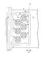
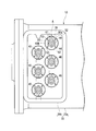
- FIG. 2 is a plan view showing the configuration of the attachment structure A of the main terminal 40 in the first embodiment of the present invention.
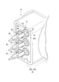
- FIG. 3 is a perspective view showing the configuration of the attachment structure A for the main terminal 40 in the first embodiment of the present invention.
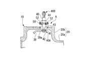
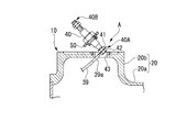
- 4 is a cross-sectional view taken along the line XX in FIG.
- the electric motor 10 of the present embodiment adopts a drive format that generates a rotating magnetic field by three-phase alternating current, and corresponds to three or multiples (six in the present embodiment) of the coils 38 in FIGS. As shown in FIG. 3, the same number (six in this embodiment) of main terminals 40 is attached to the housing 20.
- the housing 20 has a cylindrical main body 20a that houses the stator 22, the rotor 23, and the like, and a main terminal mounting portion 20b that protrudes outward from the main body 20a.
- the main terminal mounting portion 20b has a box shape protruding in the radial direction of the main body portion 20a.
- the inside of the main terminal mounting portion 20b is hollow as shown in FIG. 4 and communicates with the inside of the main body portion 20a.
- the main terminal mounting portion 20b and the main body portion 20a are integrated and formed by casting or the like.
- a plurality of main terminals 40 are attached to the main terminal attaching portion 20b in a staggered arrangement (see FIG. 2). As shown in FIG. 4, the main terminal 40 is attached to the housing 20 with one end 40 ⁇ / b> A inserted into the housing 20 and the other end 40 ⁇ / b> B exposed to the outside of the housing 20.
- the main terminal 40 has a rod shape, and is attached in a posture perpendicular to the main terminal attachment portion 20b of the housing 20 in the present embodiment.
- a lead wire 39 extending from the coil 38 can be fixed to one end 40 ⁇ / b> A of the main terminal 40.
- the lead wire 39 has a crimp terminal 39a attached to its tip.
- the lead wire 39 is electrically connected to one end portion 40A of the main terminal 40 via the crimp terminal 39a.
- One end 40A of the main terminal 40 is threaded and a nut 41 is screwed.
- the crimp terminal 39a has a hole (not shown) through which the one end 40A can be inserted. For this reason, after passing the crimp terminal 39 a through the one end 40 ⁇ / b> A of the main terminal 40, another nut 42 is attached and the crimp terminal 39 a is tightened between the nuts 41 and 42.
- the housing 20 has a mounting hole 43 for mounting the main terminal 40.
- the attachment hole 43 is a circular hole that vertically penetrates the main terminal attachment portion 20b of the housing 20.
- the mounting hole 43 has a size for inserting and extracting the one end 40A of the main terminal 40 together with the lead wire 39.
- the size of the mounting hole 43 of this embodiment is larger than at least the nuts 41 and 42.
- Such a mounting hole 43 can be formed by drilling the casing 20 with a drill.
- the lead wire 39 is housed inside the housing 20 with a slack for pulling out together with the one end 40 ⁇ / b> A of the main terminal 40 from the mounting hole 43.
- the lead wire 39 can be pulled out from the mounting hole 43 while being fixed together with the one end portion 40A of the main terminal 40.
- the main terminal 40 is provided with a flange portion 50 which is a small adapter.
- the flange part 50 is provided in the middle part between the one end part 40A and the other end part 40B.
- the flange portion 50 is integrally fixed to the main terminal 40.
- the flange portion 50 has a disk shape and has a larger diameter than the main terminal 40.
- the flange portion 50 has a larger diameter than the mounting hole 43 as shown in FIG. For this reason, the flange portion 50 can close a gap formed between the main terminal 40 and the mounting hole 43.
- a screw is cut in the middle part of the main terminal 40, and a nut 44 is screwed.
- the flange part 50 has a screw hole 51 that can be screwed into the middle part of the main terminal 40, and is fixed to the main terminal 40 integrally by tightening with the nut 44.
- a chamfering groove is formed on the fastening surface side of the flange portion 50, and a seal member 45 that seals between the flange portion 50 and the nut 44 is disposed.
- an annular groove is formed on the surface of the flange portion 50 opposite to the fastening surface, and a seal member 46 that seals between the flange portion 50 and the housing 20 is disposed.
- the flange portion 50 can be attached around the attachment hole 43 from the outside of the housing 20 without the rotation of the main terminal 40.
- the flange portion 50 can be attached to the housing 20 by a fixing bolt (fixing means) 52.
- the fixing bolt 52 is inserted into a through hole 53 provided on the outer diameter side of the flange portion 50 and screwed into a screw hole 54 provided in the main terminal mounting portion 20b of the housing 20.
- the fixing by the fixing bolt 52 is performed at equal intervals in the circumferential direction of the flange portion 50 as shown in FIG. According to such a configuration, the fixing bolt 52 allows the flange portion 50 to be attached and detached without the shaft rotation of the main terminal 40 from the outside of the housing 20.
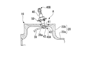
- FIGS. 5A to 5D are diagrams for explaining the replacement operation of the main terminal 40 in the first embodiment of the present invention.
- the fixing by the fixing bolt 52 is released. Since the fixing bolts 52 are exposed to the outside of the housing 20, the fixing bolts 52 can be released by screwing them. Further, as shown in FIG. 2, the fixing bolt 52 fixes the flange portion 50 to the housing 20, so that the fixing bolt 52 can be released without rotation of the main terminal 40. Thus, by providing the flange portion 50, it is not necessary to rotate the main terminal 40 at the time of removal, and the lead wire 39 fixed to the one end portion 40A inside the housing 20 is not twisted. The main terminal 40 can be removed.
- the removed main terminal 40 is inclined obliquely.
- the one end 40 ⁇ / b> A to which the lead wire 39 is fixed can pass through the mounting hole 43 provided in the housing 20 while seeing the main terminal 40 tilted further obliquely. Adjust to posture.
- the lead wire 39 is provided with a crimp terminal 39a, and a part of the crimp terminal 39a protrudes in a direction orthogonal to the axial direction of the main terminal 40. 43 can be facilitated.
- the main terminal 40 is pulled up while being inclined, thereby exposing the one end 40A to which the lead wire 39 is fixed to the outside of the housing 20. Since the attachment hole 43 is formed in such a size that the one end 40 ⁇ / b> A can be inserted and removed together with the lead wire 39, the one end 40 ⁇ / b> A can be pulled out of the housing 20 from the attachment hole 43. Further, since the lead wire 39 is housed inside the housing 20 with a certain degree of slack, the one end 40A can be pulled out to a visible position and a position where it can be easily operated.
- the one end portion 40A of the main terminal 40 to which the lead wire 39 is fixed is pulled out from the mounting hole 43 to the outside of the housing 20 by an easy operation of simply removing the flange portion 50. Can do. Therefore, the nut 42 can be loosened at a visible position to release the lead wire 39, and each of the main terminals 40 can be replaced individually. Therefore, as shown in FIG. 1, even in the case of a large motor 10 that needs to hold both ends of the rotating shaft 24 with bearings 26 and 31, only the damaged main terminal 40 is replaced without disassembling the whole. can do. For this reason, since the replacement work can be easily performed only by a manual operation without a crane, the time and labor required for the replacement work can be greatly reduced.
- the main terminal 40 is connected to the main terminal 40 in a state where the one end 40A capable of fixing the lead wire 39 is inserted into the housing 20 and the other end 40B is exposed to the outside of the housing 20.
- casing 20 is disclosed.
- the housing 20 has an attachment hole 43 for inserting and removing the one end 40 ⁇ / b> A together with the lead wire 39, and the main terminal 40 is a rotation of the main terminal 40.
- FIG. 6 is a plan view showing the configuration of the mounting structure A for the main terminal 40 in the second embodiment of the present invention. As shown in FIG. 6, the second embodiment is different from the above-described embodiment in that the mounting structure A of the main terminal 40 includes orientation adjusting means (mark 61).
- the orientation adjusting means of the second embodiment has a mark 61 for adjusting the orientation of the main terminal 40 with respect to the mounting hole 43 to a predetermined orientation.
- the predetermined direction is a direction in which the crimp terminals 39a of the lead wires 39 arranged inside the housing 20 do not face each other, and a sufficient insulation distance is maintained between the terminals. It is possible direction.
- the mark 61 is formed on the flange portion 50 corresponding to the direction in which the lead wire 39 is fixed to the one end portion 40A.
- the mark 61 of the present embodiment is formed on the flange portion 50 so as to indicate the direction in which the crimp terminal 39a of the lead wire 39 protrudes.
- the flange portion 50 arranged outside the visible housing 20 is provided with the mark 61 corresponding to the direction of the lead wire 39, so that the direction can be easily adjusted based on the mark 61. can do.
- the orientation of the main terminal 40 relative to the mounting hole 43 is adjusted to a predetermined orientation. be able to.
- the main terminal 40 can be replaced alone without disassembling the casing 20, but the inside of the casing 20 is not visible when the replacement is performed instead. Therefore, by providing the mark 61, a sufficient insulation distance of the lead wire 39 can be secured even inside the housing 20 that is not visible.
- FIG. 7 is a plan view showing the configuration of the attachment structure A for the main terminal 40 in the third embodiment of the present invention. As shown in FIG. 7, the third embodiment is different from the above-described embodiment in that the mounting structure A of the main terminal 40 includes orientation adjusting means (fixing bolt 52 (52a)).
- the orientation adjusting means of the third embodiment further includes a fixing bolt 52a in order to adjust the orientation of the main terminal 40 with respect to the mounting hole 43 to a predetermined orientation. Due to the addition of the fixing bolts 52a, the fixing bolts 52 (52a) are provided at non-uniform intervals in the circumferential direction of the flange portion 50. Further, the fixing bolt 52a fixes the flange portion 50 at a position indicating the direction in which the crimp terminal 39a of the lead wire 39 protrudes corresponding to the direction in which the lead wire 39 is fixed to the one end portion 40A.
- the fixing bolt 52a can be fixed to the flange portion 50 arranged outside the visible housing 20 in accordance with the direction of the lead wire 39, the direction is easy with the fixing bolt 52a as a mark. Can be adjusted. Further, the fixing bolts 52 (52 a) are provided at non-uniform intervals in the circumferential direction of the flange portion 50, so that the flange portion 50 can be fixed only in a certain direction with respect to the housing 20.
- the mounting posture of the flange portion 50 is restricted to a constant posture. For this reason, it cannot be fixed except in the posture, and the direction of the lead wire 39 fixed to the one end portion 40A of the main terminal 40 and disposed inside the housing 20 can be adjusted to a predetermined direction. The insulation distance of the lead wire 39 can be more reliably ensured inside the non-housing 20.
- FIG. 8 is a plan view showing the configuration of the main terminal 40 mounting structure A in the fourth embodiment of the present invention.
- FIG. 9 is a view for explaining the replacement operation of the main terminal 40 in the YY cross section in FIG.
- the fourth embodiment is different from the above-described embodiment in that the attachment hole 43 is elliptical.
- the mounting hole 43 of the fourth embodiment has an elliptical shape, and the size in the minor axis direction is at least larger than the width of the crimp terminal 39a of the lead wire 39. Further, the major axis direction of the elliptical shape of the attachment hole 43 coincides with the direction in which the crimp terminal 39a protrudes in the attached state. Further, as shown in FIG. 9, the mounting hole 43 of the third embodiment is formed in a smooth curved shape by chamfering the opening edge 43 a inside the housing 20.
- the mounting structure A of the main terminal 40 of the fourth embodiment having the above-described configuration, the following action is obtained.
- the mounting hole 43 is elliptical, as shown in FIG. 9, the main terminal 40 to which the lead wire 39 is connected is inclined and can be easily pulled out from the mounting hole 43 to the outside of the housing 20. Can do.
- the major axis direction of the elliptical shape of the mounting hole 43 coincides with the direction in which the crimp terminal 39a protrudes, the lead wire 39 is not twisted when tilted obliquely.
- the form in which the flange portion is attached to the housing with the fixing bolt has been described.
- it is a form which attaches a flange part to a housing
- the form of the mark or the non-uniformly spaced fixing means has been described as the orientation adjusting means.
- the form of adjusting the direction of the connection terminal with respect to may be a predetermined direction.
- the present invention is not limited to this form, and other connection terminals such as a sub terminal mounting structure, for example. It can also be applied to the mounting structure.
- connection terminal mounting structure of the present invention and the turbo compressor and the centrifugal chiller provided with the connection terminal mounting structure, the connection terminals can be easily exchanged.
Landscapes
- Engineering & Computer Science (AREA)
- Mechanical Engineering (AREA)
- General Engineering & Computer Science (AREA)
- Physics & Mathematics (AREA)
- Thermal Sciences (AREA)
- Power Engineering (AREA)
- Motor Or Generator Frames (AREA)
- Connections Arranged To Contact A Plurality Of Conductors (AREA)
- Structures Of Non-Positive Displacement Pumps (AREA)
Description
本発明は、接続端子の取付構造、ターボ圧縮機及びターボ冷凍機に関する。
本願は、2012年8月27日に日本国に出願された特願2012-186439号に基づき優先権を主張し、その内容をここに援用する。
本願は、2012年8月27日に日本国に出願された特願2012-186439号に基づき優先権を主張し、その内容をここに援用する。
冷凍機として、電動機によってインペラを回転させて冷媒を圧縮して排出するターボ圧縮機を備えるターボ冷凍機が知られている。ターボ圧縮機に用いられる電動機の駆動形式は様々な種類があるが、例えば、三相交流によって回転磁界を発生させる電動機においては、前記回転磁界を発生させる複数のコイルに対し、リード線を介して電気的に接続される主端子(接続端子)がその筐体に複数取り付けられている。
下記特許文献1には、一方がモーターケーシングの内部のモーター固定子に接続された複数の電線の他方を端子棒に接続し、モーターケーシングに取り付けられた端子台を介して端子棒をモーターケーシングの外部に露出させたモーター及びこれを備えた圧縮機が開示されている。このモーターの接続端子の取付構造は、モーターケーシングの内部において端子棒のフランジ部を端子台に係止させ、モーターケーシングの外部において端子棒のボルト部にナットを締め付けるように構成されている。
従来、モーター主端子のような筐体の外部に露出する接続端子が一本でも損傷した場合には、重量物のモーターエンドカバーを取り外して内部のナットを緩め、損傷した接続端子を交換していた。上記従来技術のモーターは、小型のロータが片持ち状態(特許文献1の図1参照)となっているため、モーターエンドカバー(端子台)を容易に取り外すことができる。
しかしながら、例えば大型のモーターの場合には、ロータの両端を軸受で保持する必要がある。そのため、損傷した接続端子を交換するためだけにモーター全体を一旦解体する大掛かりな分解作業が必要となる場合がある。このような大掛かりな分解作業は、部品一つ一つが大型で重量があるためにクレーン等を必要とし、作業が煩雑で時間がかかる可能性がある。
しかしながら、例えば大型のモーターの場合には、ロータの両端を軸受で保持する必要がある。そのため、損傷した接続端子を交換するためだけにモーター全体を一旦解体する大掛かりな分解作業が必要となる場合がある。このような大掛かりな分解作業は、部品一つ一つが大型で重量があるためにクレーン等を必要とし、作業が煩雑で時間がかかる可能性がある。
本発明は、上記事情に鑑みてなされたものであり、接続端子の交換を容易に行うことのできる接続端子の取付構造、及び、上記接続端子の取付構造を備えるターボ圧縮機及びターボ冷凍機の提供を目的とする。
本発明の第一の態様は、リード線を固定可能な一端部が筐体の内部に挿入され、他端部が前記筐体の外部に露出した状態で、接続端子を前記筐体に取り付ける接続端子の取付構造であって、前記筐体は、前記一端部を前記リード線と共に挿抜させるための取付穴を有し、前記接続端子に設けられ、前記接続端子の回転を伴うことなく前記筐体の外部から前記取付穴の周りに前記接続端子を取り付け可能なフランジ部を有する。
本発明の第一の態様では、フランジ部を取り外すだけの容易な作業で、リード線が固定された接続端子の一端部を取付穴から筐体の外部に引き出すことができ、目に見える位置でリード線の固定を解除し、接続端子を単独で交換することができる。
本発明の第一の態様では、フランジ部を取り外すだけの容易な作業で、リード線が固定された接続端子の一端部を取付穴から筐体の外部に引き出すことができ、目に見える位置でリード線の固定を解除し、接続端子を単独で交換することができる。
本発明の第二の態様は、第一の態様において、前記取付穴に対する前記接続端子の向きを予め定められた向きに調整する向き調整手段を有する。
本発明の第二の態様では、取付穴に対する接続端子の向きを一定に調整することで、接続端子の一端部に固定され筐体の内部に配置されるリード線の向きをある特定の向きに調整することができるため、目に見えない筐体の内部においてリード線の絶縁距離を十分に確保することができる。
本発明の第二の態様では、取付穴に対する接続端子の向きを一定に調整することで、接続端子の一端部に固定され筐体の内部に配置されるリード線の向きをある特定の向きに調整することができるため、目に見えない筐体の内部においてリード線の絶縁距離を十分に確保することができる。
本発明の第三の態様は、第二の態様において、前記向き調整手段は、前記リード線が前記一端部に固定された向きに対応して前記フランジ部に形成された目印を有する。
本発明の第三の態様では、目に見える筐体の外部に配置されるフランジ部に、リード線の向きに対応して目印が付されているので、この目印に基づいて向きを調整することで、目に見えない筐体の内部においてリード線の絶縁距離を十分に確保することができる。
本発明の第三の態様では、目に見える筐体の外部に配置されるフランジ部に、リード線の向きに対応して目印が付されているので、この目印に基づいて向きを調整することで、目に見えない筐体の内部においてリード線の絶縁距離を十分に確保することができる。
本発明の第四の態様は、第二、又は第三の態様において、前記向き調整手段は、前記フランジ部の周方向において非等間隔で設けられた固定手段を有する。
本発明の第四の態様では、フランジ部がある一定の向きでしか固定できなくなるため、接続端子の一端部に固定され筐体の内部に配置されるリード線の向きをある特定の向きに調整することができ、目に見えない筐体の内部においてリード線の絶縁距離を十分に確保することができる。
本発明の第四の態様では、フランジ部がある一定の向きでしか固定できなくなるため、接続端子の一端部に固定され筐体の内部に配置されるリード線の向きをある特定の向きに調整することができ、目に見えない筐体の内部においてリード線の絶縁距離を十分に確保することができる。
本発明の第五の態様は、第一から第四のいずれかの態様において、前記取付穴は、楕円形状である。
本発明の第五の態様では、リード線が接続された接続端子を斜めにして楕円形状の取付穴から筐体の外部に容易に引き出すことができる。
本発明の第五の態様では、リード線が接続された接続端子を斜めにして楕円形状の取付穴から筐体の外部に容易に引き出すことができる。
本発明の第六の態様は、第一から第五のいずれかの態様において、前記リード線は、前記取付穴から引き出されるための弛みを有している。
本発明の第六の態様では、リード線がある程度の弛みをもって筐体の内部に収容されるため、目に見える位置で且つ作業し易い位置までリード線を引き出して、接続端子の交換をし易くすることができる。
本発明の第六の態様では、リード線がある程度の弛みをもって筐体の内部に収容されるため、目に見える位置で且つ作業し易い位置までリード線を引き出して、接続端子の交換をし易くすることができる。
本発明の第七の態様は、電動機によってインペラを回転させて気体を圧縮するターボ圧縮機であって、前記電動機の接続端子の取付構造として、第一から第六のいずれかの態様の接続端子の取付構造を有する。
本発明の第八の態様は、圧縮された冷媒を液化する凝縮器と、前記凝縮器によって前記液化された冷媒を蒸発させて冷却対象物を冷却する蒸発器と、前記蒸発器によって前記蒸発された冷媒を圧縮して前記凝縮器に供給するターボ圧縮機と、を有するターボ冷凍機であって、前記ターボ圧縮機として、第七の態様のターボ圧縮機を有する。
本発明によれば、接続端子の交換を容易に行うことのできる接続端子の取付構造、及び、前記接続端子の取付構造を備えるターボ圧縮機及びターボ冷凍機が得られる。
以下、本発明の実施形態について図面を参照して説明する。
(第1実施形態)
図1は、本発明の第1実施形態におけるターボ冷凍機1の系統図である。
本実施形態のターボ冷凍機1は、例えばフロンを冷媒として、空調用の冷水を冷却対象物とする。ターボ冷凍機1は、図1に示すように、凝縮器2と、エコノマイザ3と、蒸発器4と、ターボ圧縮機5と、を備えている。
図1は、本発明の第1実施形態におけるターボ冷凍機1の系統図である。
本実施形態のターボ冷凍機1は、例えばフロンを冷媒として、空調用の冷水を冷却対象物とする。ターボ冷凍機1は、図1に示すように、凝縮器2と、エコノマイザ3と、蒸発器4と、ターボ圧縮機5と、を備えている。
凝縮器2は、流路R1を介してターボ圧縮機5のガス吐出管5aと接続されている。凝縮器2には、ターボ圧縮機5によって圧縮された冷媒(圧縮冷媒ガスX1)が流路R1を通って供給される。凝縮器2は、この圧縮冷媒ガスX1を液化する。凝縮器2は、冷却水が流通する伝熱管2aを備え、圧縮冷媒ガスX1と冷却水との間の熱交換によって、圧縮冷媒ガスX1を冷却する。
圧縮冷媒ガスX1は、冷却水との間の熱交換によって冷却され、液化し、冷媒液X2となって凝縮器2の底部に溜まる。凝縮器2の底部は、流路R2を介してエコノマイザ3と接続されている。流路R2には、冷媒液X2を減圧するための膨張弁6が設けられている。エコノマイザ3には、膨張弁6によって減圧された冷媒液X2が流路R2を通って供給される。エコノマイザ3は、減圧された冷媒液X2を一時的に貯留し、冷媒を液相と気相とに分離する。
エコノマイザ3の頂部は、流路R3を介してターボ圧縮機5のエコノマイザ連結管5bと接続されている。ターボ圧縮機5には、エコノマイザ3によって分離した冷媒の気相成分X3が、蒸発器4及び第1圧縮段11を経ることなく、流路R3を通って第2圧縮段12に供給され、効率を高める。一方、エコノマイザ3の底部は、流路R4を介して蒸発器4と接続されている。流路R4には、冷媒液X2をさらに減圧するための膨張弁7が設けられている。
蒸発器4には、膨張弁7によってさらに減圧された冷媒液X2が流路R4を通って供給される。蒸発器4は、冷媒液X2を蒸発させてその気化熱によって冷水を冷却する。蒸発器4は、冷水が流通する伝熱管4aを備え、冷媒液X2と冷水との間の熱交換によって、冷水を冷却すると共に冷媒液X2を蒸発させる。冷媒液X2は、冷水との間の熱交換によって熱を奪って蒸発し、冷媒ガスX4となる。
蒸発器4の頂部は、流路R5を介してターボ圧縮機5のガス吸入管5cと接続されている。ターボ圧縮機5には、蒸発器4において蒸発した冷媒ガスX4が流路R5を通って供給される。ターボ圧縮機5は、蒸発した冷媒ガスX4を圧縮し、圧縮冷媒ガスX1として凝縮器2に供給する。ターボ圧縮機5は、冷媒ガスX4を圧縮する第1圧縮段11と、一段階圧縮された冷媒をさらに圧縮する第2圧縮段12と、を備える2段圧縮機である。
第1圧縮段11にはインペラ13が設けられ、第2圧縮段12にはインペラ14が設けられており、それらが回転軸15で接続されている。ターボ圧縮機5は、電動機10によってインペラ13,14を回転させて冷媒を圧縮する。インペラ13,14は、ラジアルインペラであり、軸方向で吸気した冷媒を半径方向に排出する不図示の3次元的ねじれを含むブレードを有する。
ガス吸入管5cには、第1圧縮段11の吸入量を調節するためのインレットガイドベーン16が設けられている。インレットガイドベーン16は、冷媒ガスX4の流れ方向からの見かけ上の面積が変更可能なように回転可能とされている。インペラ13,14の周りには、それぞれディフューザ流路が設けられており、半径方向に排出した冷媒を、これらの流路において圧縮・昇圧する。さらにインペラ13,14の周りに設けられたスクロール流路によって次の圧縮段に供給することができる。インペラ14の周りには、出口絞り弁17が設けられており、ガス吐出管5aからの吐出量を制御できる。
ターボ圧縮機5は、密閉型の筐体20を備える。筐体20は、圧縮流路空間S1と、第1の軸受収容空間S2と、モーター収容空間S3と、ギヤユニット収容空間S4と、第2の軸受収容空間S5と、に区画されている。圧縮流路空間S1には、インペラ13,14が設けられている。インペラ13,14を接続する回転軸15は、圧縮流路空間S1、第1の軸受収容空間S2、ギヤユニット収容空間S4に挿通して設けられている。第1の軸受収容空間S2には、回転軸15を支持する軸受21が設けられている。
モーター収容空間S3には、ステータ22と、ロータ23と、ロータ23に接続された回転軸24と、が設けられている。この回転軸24は、モーター収容空間S3、ギヤユニット収容空間S4、第2の軸受収容空間S5に挿通して設けられている。第2の軸受収容空間S5には、回転軸24の反負荷側を支持する軸受31が設けられている。ギヤユニット収容空間S4には、ギヤユニット25と、軸受26,27と、オイルタンク28と、が設けられている。
ギヤユニット25は、回転軸24に固定される大径歯車29と、回転軸15に固定されると共に大径歯車29と噛み合う小径歯車30と、を有する。ギヤユニット25は、回転軸24の回転数に対して回転軸15の回転数が増加(増速)するように、回転力を伝達する。軸受26は、回転軸24を支持するものである。軸受27は、回転軸15を支持する。オイルタンク28は、軸受21,26,27,31等の各摺動部位に供給される潤滑油を貯溜する。なお、符号37は、各摺動部位に潤滑油を供給する給油ポンプである。
このような筐体20には、圧縮流路空間S1と第1の軸受収容空間S2との間において、回転軸15の周囲をシールするシール部32,33が設けられている。また、筐体20には、圧縮流路空間S1とギヤユニット収容空間S4との間において、回転軸15の周囲をシールするシール部34が設けられている。また、筐体20には、ギヤユニット収容空間S4とモーター収容空間S3との間において、回転軸24の周囲をシールするシール部35が設けられている。また、筐体20には、モーター収容空間S3と第2の軸受収容空間S5との間において、回転軸24の周囲をシールするシール部36が設けられている。
ここで、筐体20には、密閉型の容器内部に収容されたステータ22の複数のコイル38に対して外部から交流電流を供給するための主端子(接続端子)40が複数取り付けられている。
以下、この主端子40の取付構造の構成について、図2~図4を参照して説明する。
以下、この主端子40の取付構造の構成について、図2~図4を参照して説明する。
図2は、本発明の第1実施形態における主端子40の取付構造Aの構成を示す平面図である。図3は、本発明の第1実施形態における主端子40の取付構造Aの構成を示す斜視図である。図4は、図2における矢視X-X断面図である。
本実施形態の電動機10は、三相交流によって回転磁界を発生させる駆動形式を採用しており、3つまたはその倍数(本実施形態では6つ)のコイル38に対応して、図2及び図3に示すように、それと同数(本実施形態では6つ)の主端子40が筐体20に取り付けられている。
本実施形態の電動機10は、三相交流によって回転磁界を発生させる駆動形式を採用しており、3つまたはその倍数(本実施形態では6つ)のコイル38に対応して、図2及び図3に示すように、それと同数(本実施形態では6つ)の主端子40が筐体20に取り付けられている。
図3に示すように、筐体20は、ステータ22やロータ23等を収容する円筒状の本体部20aと、本体部20aから外方に突出した主端子取付部20bとを有する。主端子取付部20bは、本体部20aの半径方向に突出した箱形状を有している。主端子取付部20bの内部は、図4に示すように中空であり、本体部20aの内部と連通している。主端子取付部20bと本体部20aとは、一体であり、鋳造等によって形成されている。
この主端子取付部20bには、主端子40が千鳥配置(図2参照)で複数取り付けられている。主端子40は、図4に示すように、一端部40Aが筐体20の内部に挿入され、他端部40Bが筐体20の外部に露出した状態で、筐体20に取り付けられている。主端子40は、棒状であり、本実施形態では筐体20の主端子取付部20bに対して垂直な姿勢で取り付けられている。主端子40の一端部40Aには、コイル38から延びるリード線39が固定できる。
リード線39は、その先端に圧着端子39aが取り付けられている。リード線39は、圧着端子39aを介して、主端子40の一端部40Aと電気的導通を取っている。主端子40の一端部40Aには、ネジが切られており、ナット41が螺合している。圧着端子39aには、一端部40Aが挿通可能な不図示の穴が形成されている。このため、主端子40の一端部40Aに圧着端子39aを通した後、もう一つのナット42を取り付け、ナット41,42との間で圧着端子39aを締め付ける。
なお、主端子40の一端部40Aにおけるリード線39の固定を解除する場合には、ナット42を緩めて取り外し、一端部40Aから圧着端子39aを抜き取る。このように、主端子40の一端部40Aにおいては、ナット42の締め付け状態によって、リード線39を固定できる。
図4に示すように、筐体20は、主端子40を取り付けるための取付穴43を有する。取付穴43は、筐体20の主端子取付部20bを垂直に貫通する円形の穴である。
図4に示すように、筐体20は、主端子40を取り付けるための取付穴43を有する。取付穴43は、筐体20の主端子取付部20bを垂直に貫通する円形の穴である。
取付穴43は、主端子40の一端部40Aをリード線39と共に挿抜させるための大きさを有している。本実施形態の取付穴43の大きさは、少なくともナット41,42よりも大きい。このような取付穴43は、筐体20にドリルで穴あけ加工等することにより形成することができる。リード線39は、取付穴43から主端子40の一端部40Aと共に引き出されるための弛みをもって筐体20の内部に収容されている。このように、リード線39は、主端子40の一端部40Aと共に固定状態のまま取付穴43から引き出すことができる。
主端子40には、小型アダプタであるフランジ部50が設けられている。フランジ部50は、一端部40Aと他端部40Bとの間の中腹部に設けられている。フランジ部50は、主端子40に一体的に固定されている。このフランジ部50は、図2及び図3に示すように、円板形状となっており、主端子40よりも大きな径を有している。また、このフランジ部50は、図4に示すように取付穴43よりも大きな径を有している。このため、フランジ部50は、主端子40と取付穴43との間に形成される隙間を閉塞できる。
主端子40の中腹部には、ネジが切られており、ナット44が螺合している。フランジ部50は、主端子40の中腹部に螺合可能なネジ穴51を有し、ナット44と締め付け合うことで、主端子40に一体的に固定されている。フランジ部50の締め付け面側には、面取り溝が形成され、フランジ部50及びナット44の間をシールするシール部材45が配置されている。一方、フランジ部50の締め付け面とは反対の面側には、環状の溝が形成され、フランジ部50及び筐体20の間をシールするシール部材46が配置されている。
フランジ部50は、主端子40の回転を伴うことなく筐体20の外部から取付穴43の周りに取り付け可能である。フランジ部50は、固定ボルト(固定手段)52によって筐体20に対して取り付け可能である。固定ボルト52は、フランジ部50の外径側に設けられた貫通穴53を挿通し、筐体20の主端子取付部20bに設けられたネジ穴54に螺合する。固定ボルト52による固定は、図2に示すように、フランジ部50の周方向において等間隔で行われる。このような構成によれば、固定ボルト52によって、フランジ部50が筐体20の外部から主端子40の軸回転を伴うことなく、その取り付け及び取り外しを行うことができる。
続いて、上記構成の主端子40の取付構造Aの作用について図5Aから図5Dを参照して説明する。
図5Aから図5Dは、本発明の第1実施形態における主端子40の交換作業を説明するための図である。
図5Aから図5Dは、本発明の第1実施形態における主端子40の交換作業を説明するための図である。
主端子40を交換するためには、先ず、図5Aに示すように、固定ボルト52による固定を解除する。固定ボルト52は、筐体20の外部に露出しているため、それらをネジ回しすることで固定を解除することができる。また、固定ボルト52は、図2に示すように、フランジ部50を筐体20に固定するため、主端子40の回転を伴うことなく固定解除を行うことができる。このように、フランジ部50を設けることで、取り外しの際に主端子40を回転させる必要がなくなり、筐体20の内部において一端部40Aに固定されたリード線39が捩られてしまうことなく、主端子40を取り外すことができる。
次に、図5Bに示すように、取り外した主端子40を斜めに傾ける。そして、図5Cに示すように、主端子40をさらに斜めに傾けつつ様子を見ながら、リード線39が固定された一端部40Aが、筐体20に設けられた取付穴43を通過できるような姿勢に調整する。リード線39には、圧着端子39aが設けられており、主端子40の軸方向と直交する方向に圧着端子39aの一部が突出しているため、この突出部を斜めにすることで、取付穴43を通過しやすくすることができる。
その後、図5Dに示すように、主端子40を斜めに傾けつつ引き上げることによって、リード線39が固定されている一端部40Aを筐体20の外部に露出させる。取付穴43は、一端部40Aをリード線39と共に挿抜させることができる大きさに形成されているので、一端部40Aを取付穴43から筐体20の外部に引き出すことができる。また、リード線39は、ある程度の弛みをもって筐体20の内部に収容されているため、目に見える位置で且つ作業し易い位置まで一端部40Aを引き出すことができる。
このように、本実施形態によれば、フランジ部50を取り外すだけの容易な作業で、リード線39が固定された主端子40の一端部40Aを取付穴43から筐体20の外部に引き出すことができる。そのため、目に見える位置でナット42を緩めてリード線39の固定を解除し、主端子40の一本一本を単独で交換することができる。したがって、図1に示すように、回転軸24の両端を軸受26,31で保持する必要がある大型の電動機10であっても、全体を解体することなく、損傷等した主端子40のみを交換することができる。このため、クレーン不要の手作業のみで容易に交換作業を行えるため、この交換作業に要する時間と労力を大幅に軽減することができる。
したがって、上述の第一実施形態は、リード線39を固定可能な一端部40Aが筐体20の内部に挿入され、他端部40Bが筐体20の外部に露出した状態で、主端子40を筐体20に取り付けるための主端子40の取付構造Aを開示する。第一実施形態における主端子40の取付構造Aでは、筐体20は、一端部40Aをリード線39と共に挿抜させるための取付穴43を有し、さらに、主端子40は、主端子40の回転を伴うことなく筐体20の外部から取付穴43の周りに主端子40を取り付け可能なフランジ部50を有することによって、主端子40の交換を単独で容易に行うことができる。
(第2実施形態)
次に、本発明の第2実施形態について説明する。以下の説明において、第一実施形態と同一又は同等の構成を有する部分については同一の符号を付し、その説明を簡略若しくは省略する。
次に、本発明の第2実施形態について説明する。以下の説明において、第一実施形態と同一又は同等の構成を有する部分については同一の符号を付し、その説明を簡略若しくは省略する。
図6は、本発明の第2実施形態における主端子40の取付構造Aの構成を示す平面図である。
図6に示すように、第2実施形態では、主端子40の取付構造Aが向き調整手段(目印61)を有する点で、上記実施形態と異なる。
図6に示すように、第2実施形態では、主端子40の取付構造Aが向き調整手段(目印61)を有する点で、上記実施形態と異なる。
第2実施形態の向き調整手段は、取付穴43に対する主端子40の向きを予め定められた向きに調整するための目印61を有する。ここで、予め定められた向きとは、筐体20の内部に配置されたリード線39のそれぞれの圧着端子39aが互いに向き合わないような向きであり、端子間において十分な絶縁距離を保つことができる向きである。目印61は、リード線39が一端部40Aに固定された向きに対応してフランジ部50に形成されている。本実施形態の目印61は、リード線39の圧着端子39aが突出している向きを指し示すようにフランジ部50に形成されている。
上記第2実施形態の主端子40の取付構造Aによれば、次の作用が得られる。
本実施形態では、目に見える筐体20の外部に配置されるフランジ部50に、リード線39の向きに対応して目印61が付されているので、目印61に基づいて向きを容易に調整することができる。取付穴43に対する主端子40の向きを一定に調整することで、主端子40の一端部40Aに固定され筐体20の内部に配置されるリード線39の向きをある定められた向きに調整することができる。
本実施形態では、目に見える筐体20の外部に配置されるフランジ部50に、リード線39の向きに対応して目印61が付されているので、目印61に基づいて向きを容易に調整することができる。取付穴43に対する主端子40の向きを一定に調整することで、主端子40の一端部40Aに固定され筐体20の内部に配置されるリード線39の向きをある定められた向きに調整することができる。
すなわち、上述した取付構造Aによれば、筐体20を解体することなく主端子40を単独で交換できるが、代わりに交換の際に筐体20の内部が見えなくなる。そのため、目印61を設けることで、目に見えない筐体20の内部においてもリード線39の絶縁距離を十分に確保することができる。
(第3実施形態)
次に、本発明の第3実施形態について説明する。以下の説明において、第一又は第二実施形態と同一又は同等の構成を有する部分については同一の符号を付し、その説明を簡略若しくは省略する。
次に、本発明の第3実施形態について説明する。以下の説明において、第一又は第二実施形態と同一又は同等の構成を有する部分については同一の符号を付し、その説明を簡略若しくは省略する。
図7は、本発明の第3実施形態における主端子40の取付構造Aの構成を示す平面図である。
図7に示すように、第3実施形態では、主端子40の取付構造Aが向き調整手段(固定ボルト52(52a))を有する点で、上記実施形態と異なる。
図7に示すように、第3実施形態では、主端子40の取付構造Aが向き調整手段(固定ボルト52(52a))を有する点で、上記実施形態と異なる。
第3実施形態の向き調整手段は、取付穴43に対する主端子40の向きを予め定められた向きに調整するために、固定ボルト52aをさらに有する。固定ボルト52aの追加によって、固定ボルト52(52a)は、フランジ部50の周方向において非等間隔で設けられている。また、固定ボルト52aは、リード線39が一端部40Aに固定された向きに対応して、リード線39の圧着端子39aが突出している向きを指し示すような位置でフランジ部50を固定する。
上記構成の第3実施形態の主端子40の取付構造Aによれば、次の作用が得られる。
本実施形態では、目に見える筐体20の外部に配置されるフランジ部50に、リード線39の向きに対応して固定ボルト52aが固定できるため、前記固定ボルト52aを目印にして向きを容易に調整することができる。また、固定ボルト52(52a)が、フランジ部50の周方向において非等間隔で設けられることにより、フランジ部50が筐体20に対してある一定の向きでしか固定できなくなる。
本実施形態では、目に見える筐体20の外部に配置されるフランジ部50に、リード線39の向きに対応して固定ボルト52aが固定できるため、前記固定ボルト52aを目印にして向きを容易に調整することができる。また、固定ボルト52(52a)が、フランジ部50の周方向において非等間隔で設けられることにより、フランジ部50が筐体20に対してある一定の向きでしか固定できなくなる。
すなわち、上述した取付構造Aによれば、フランジ部50の取り付け姿勢が一定の姿勢に規制される。そのため、その姿勢以外では固定できなくなり、主端子40の一端部40Aに固定され筐体20の内部に配置されるリード線39の向きを予め定められた向きに調整することができ、目に見えない筐体20の内部においてリード線39の絶縁距離をより確実に確保することができる。
(第4実施形態)
次に、本発明の第4実施形態について説明する。以下の説明において、第一、第二、第三の実施形態と同一又は同等の構成を有する部分については同一の符号を付し、その説明を簡略若しくは省略する。
次に、本発明の第4実施形態について説明する。以下の説明において、第一、第二、第三の実施形態と同一又は同等の構成を有する部分については同一の符号を付し、その説明を簡略若しくは省略する。
図8は、本発明の第4実施形態における主端子40の取付構造Aの構成を示す平面図である。図9は、図8における矢視Y-Y断面での主端子40の交換作業を説明する図である。
図8に示すように、第4実施形態では、取付穴43が楕円形状である点で、上記実施形態と異なる。
図8に示すように、第4実施形態では、取付穴43が楕円形状である点で、上記実施形態と異なる。
第四実施形態の取付穴43は、楕円形状とされており、その短軸方向の大きさは、少なくともリード線39の圧着端子39aの幅より大きくなっている。また、取付穴43の楕円形状の長軸方向は、取り付け状態で圧着端子39aが突出する方向と一致している。また、第3実施形態の取付穴43は、図9に示すように、筐体20の内部の開口縁部43aが面取りされ滑らかなカーブ状に形成されている。
上記構成の第4実施形態の主端子40の取付構造Aによれば、次の作用が得られる。
本実施形態では、取付穴43が楕円形状であるため、図9に示すように、リード線39が接続された主端子40を斜めにして取付穴43から筐体20の外部に容易に引き出すことができる。また、取付穴43の楕円形状の長軸方向が圧着端子39aが突出する方向と一致するため、斜めに傾ける際にリード線39を捩ることはない。
本実施形態では、取付穴43が楕円形状であるため、図9に示すように、リード線39が接続された主端子40を斜めにして取付穴43から筐体20の外部に容易に引き出すことができる。また、取付穴43の楕円形状の長軸方向が圧着端子39aが突出する方向と一致するため、斜めに傾ける際にリード線39を捩ることはない。
すなわち、上述した取付構造Aによれば、引き出しの際には隙間の余裕が生まれるため、リード線39が開口縁部43aに引っ掛かることなく取付穴43を滑らかに通過することができ、リード線39が固定された主端子40の一端部40Aを取付穴43から筐体20の外部に容易に引き出すことができる。
以上、図面を参照しながら本発明の好適な実施形態について説明したが、本発明は上記実施形態に限定されない。上述した実施形態において示した各構成部材の諸形状や組み合わせ等は一例であって、本発明の主旨から逸脱しない範囲において設計要求等に基づき種々変更可能である。
例えば、上記実施形態では、固定ボルトによりフランジ部を筐体に取り付ける形態について説明したが、本発明はこの形態に限定されない。例えば、嵌め込みによりフランジ部を筐体に取り付ける形態であっても、上記実施形態と同様に主端子の回転を伴うことなく取り付け自在な構成とすることができる。
また、例えば、上記実施形態では、向き調整手段として目印や非等間隔配置の固定手段の形態について説明したが、本発明はこの形態に限定されることなく、例えば位置決めピン等を設けて取付穴に対する接続端子の向きを予め定められた向きに調整する形態であってもよい。
また、例えば、上記実施形態では、主端子の取付構造に本発明を適用した形態について説明したが、本発明はこの形態に限定されることなく、例えば副端子の取付構造等、他の接続端子の取付構造にも適用可能である。
本発明の接続端子の取付構造、及び、前記接続端子の取付構造を備えるターボ圧縮機及びターボ冷凍機によれば、接続端子の交換を容易に行うことができる。
1 ターボ冷凍機
2 凝縮器
4 蒸発器
5 ターボ圧縮機
10 電動機
13,14 インペラ
20 筐体
39 リード線
40 主端子(接続端子)
40A 一端部
40B 他端部
43 取付穴
50 フランジ部
52,52a 固定ボルト(固定手段、向き調整手段)
61 目印(向き調整手段)
2 凝縮器
4 蒸発器
5 ターボ圧縮機
10 電動機
13,14 インペラ
20 筐体
39 リード線
40 主端子(接続端子)
40A 一端部
40B 他端部
43 取付穴
50 フランジ部
52,52a 固定ボルト(固定手段、向き調整手段)
61 目印(向き調整手段)
Claims (8)
- リード線を固定可能な一端部が筐体の内部に挿入され、他端部が前記筐体の外部に露出した状態で、接続端子を前記筐体に取り付ける接続端子の取付構造であって、
前記筐体は、前記一端部を前記リード線と共に挿抜させるための取付穴を有し、
前記接続端子は、前記接続端子の回転を伴うことなく前記筐体の外部から前記取付穴の周りに前記接続端子を取り付け可能なフランジ部を有する接続端子の取付構造。 - 前記取付穴に対する前記接続端子の向きを予め定められた向きに調整する向き調整手段を有する請求項1に記載の接続端子の取付構造。
- 前記向き調整手段は、前記リード線が前記一端部に固定された向きに対応して前記フランジ部に形成された目印を有する請求項2に記載の接続端子の取付構造。
- 前記向き調整手段は、前記フランジ部の周方向において非等間隔で設けられた固定手段を有する請求項2または3に記載の接続端子の取付構造。
- 前記取付穴は、楕円形状とされている請求項1~4のいずれか一項に記載の接続端子の取付構造。
- 前記リード線は、前記取付穴から引き出されるための弛みを有している請求項1~5のいずれか一項に記載の接続端子の取付構造。
- 電動機によってインペラを回転させて気体を圧縮するターボ圧縮機であって、
前記電動機の接続端子の取付構造として、請求項1~6のいずれか一項に記載の接続端子の取付構造を有するターボ圧縮機。 - 圧縮された冷媒を液化する凝縮器と、
前記凝縮器によって前記液化された冷媒を蒸発させて冷却対象物を冷却する蒸発器と、
前記蒸発器によって前記蒸発された冷媒を圧縮して前記凝縮器に供給するターボ圧縮機と、を有するターボ冷凍機であって、
前記ターボ圧縮機として、請求項7に記載のターボ圧縮機を有するターボ冷凍機。
Priority Applications (2)
| Application Number | Priority Date | Filing Date | Title |
|---|---|---|---|
| CN201380044356.9A CN104541410B (zh) | 2012-08-27 | 2013-07-25 | 涡轮压缩机以及涡轮冷冻机 |
| US14/626,310 US9431730B2 (en) | 2012-08-27 | 2015-02-19 | Mounting structure for connection terminal, turbo compressor, and turbo refrigerator |
Applications Claiming Priority (2)
| Application Number | Priority Date | Filing Date | Title |
|---|---|---|---|
| JP2012-186439 | 2012-08-27 | ||
| JP2012186439A JP5991077B2 (ja) | 2012-08-27 | 2012-08-27 | 接続端子の取付構造、ターボ圧縮機及びターボ冷凍機 |
Related Child Applications (1)
| Application Number | Title | Priority Date | Filing Date |
|---|---|---|---|
| US14/626,310 Continuation US9431730B2 (en) | 2012-08-27 | 2015-02-19 | Mounting structure for connection terminal, turbo compressor, and turbo refrigerator |
Publications (1)
| Publication Number | Publication Date |
|---|---|
| WO2014034337A1 true WO2014034337A1 (ja) | 2014-03-06 |
Family
ID=50183157
Family Applications (1)
| Application Number | Title | Priority Date | Filing Date |
|---|---|---|---|
| PCT/JP2013/070182 Ceased WO2014034337A1 (ja) | 2012-08-27 | 2013-07-25 | 接続端子の取付構造、ターボ圧縮機及びターボ冷凍機 |
Country Status (4)
| Country | Link |
|---|---|
| US (1) | US9431730B2 (ja) |
| JP (1) | JP5991077B2 (ja) |
| CN (1) | CN104541410B (ja) |
| WO (1) | WO2014034337A1 (ja) |
Cited By (2)
| Publication number | Priority date | Publication date | Assignee | Title |
|---|---|---|---|---|
| JP2016131067A (ja) * | 2015-01-13 | 2016-07-21 | 株式会社豊田自動織機 | 端子台装置 |
| JP2016211537A (ja) * | 2015-04-30 | 2016-12-15 | プファイファー・ヴァキューム・ゲーエムベーハー | 真空ポンプ及び真空ポンプの製造の為の方法 |
Families Citing this family (6)
| Publication number | Priority date | Publication date | Assignee | Title |
|---|---|---|---|---|
| WO2010056894A1 (en) | 2008-11-13 | 2010-05-20 | Packsize, Llc | Box gluing device |
| US8334457B2 (en) * | 2009-02-20 | 2012-12-18 | Clean Wave Technologies Inc. | System for power connection |
| JP5991077B2 (ja) * | 2012-08-27 | 2016-09-14 | ダイキン工業株式会社 | 接続端子の取付構造、ターボ圧縮機及びターボ冷凍機 |
| JP6903534B2 (ja) * | 2017-09-21 | 2021-07-14 | Ntn株式会社 | インホイールモータ駆動装置 |
| US10790557B2 (en) | 2017-12-11 | 2020-09-29 | Ford Global Technologies, Llc | Methods and systems for electric turbo |
| US10790601B1 (en) * | 2019-11-25 | 2020-09-29 | TE Connectivity Services Gmbh | Electrical conductor pass through plate constructions |
Citations (5)
| Publication number | Priority date | Publication date | Assignee | Title |
|---|---|---|---|---|
| JPS5841046U (ja) * | 1981-09-09 | 1983-03-18 | 神鋼電機株式会社 | 回転電機の端子構造 |
| JPH0658560U (ja) * | 1993-01-22 | 1994-08-12 | 矢崎総業株式会社 | 機器直付用シールドコネクタ |
| JP2007166822A (ja) * | 2005-12-15 | 2007-06-28 | Mitsubishi Electric Corp | 多相交流回転電機 |
| JP2010268622A (ja) * | 2009-05-15 | 2010-11-25 | Kobe Steel Ltd | モータ及びこれを備えた圧縮機 |
| JP2011223679A (ja) * | 2010-04-06 | 2011-11-04 | Ihi Corp | ターボ圧縮機及びターボ冷凍機 |
Family Cites Families (28)
| Publication number | Priority date | Publication date | Assignee | Title |
|---|---|---|---|---|
| US1526023A (en) * | 1918-10-12 | 1925-02-10 | Steinberger Louis | Insulated ventilating connecter |
| US2438572A (en) * | 1944-05-11 | 1948-03-30 | Gen Motors Corp | Terminal structure for refrigerating apparatus |
| US2418729A (en) * | 1945-10-01 | 1947-04-08 | William J Schemers | Auxiliary terminal for sealed-in motor compressor units |
| US2742624A (en) * | 1953-07-08 | 1956-04-17 | Whitney Blake Co | Electrical plug and socket assembly |
| US2997530A (en) * | 1958-04-21 | 1961-08-22 | Rosan Eng Corp | Through terminal and mounting for sheet elements |
| US3321733A (en) * | 1964-04-03 | 1967-05-23 | Amp Inc | High voltage and altitude connector means |
| US3696321A (en) * | 1970-09-14 | 1972-10-03 | Itt | Electrical connector |
| US3708612A (en) * | 1971-07-02 | 1973-01-02 | Anderson Electric Corp | Electrical bushing assembly |
| US3850501A (en) * | 1973-04-09 | 1974-11-26 | Gen Electric | Feedthrough electrical terminal for hollow liquid cooled shaft of a dynamoelectric machine |
| IT1145925B (it) | 1981-08-19 | 1986-11-12 | Nespak Spa | Cassa o cassetta componibile ed accatastabiledi materia plastica per l imballaggio in particolare di prodotti ortofrutticoli |
| JPS5851479A (ja) * | 1981-09-18 | 1983-03-26 | 富士通株式会社 | 電源端子板 |
| US4800732A (en) * | 1988-04-28 | 1989-01-31 | American Standard Inc. | Refrigeration compressor with dual voltage hookup |
| US5227587A (en) * | 1991-05-13 | 1993-07-13 | Emerson Electric Co. | Hermetic assembly arrangement for a current conducting pin passing through a housing wall |
| US5110307B1 (en) * | 1991-07-09 | 1994-09-20 | Balo Precision Parts Inc | Laser weldable hermetic connector |
| US5342998A (en) * | 1992-04-02 | 1994-08-30 | General Electric Company | Terminal bushing for electrical apparatus comprising a polymeric shell molded about a central conductor |
| US5308925A (en) * | 1992-06-26 | 1994-05-03 | Emerson Electric Co. | Conductive pin assembly for a machine housing |
| JP2904242B2 (ja) | 1992-08-06 | 1999-06-14 | 東京瓦斯株式会社 | 床暖房装置を組み合わせたセントラルヒーティングシステムにおける運転制御方法 |
| JP3741343B2 (ja) * | 1999-01-21 | 2006-02-01 | 矢崎総業株式会社 | シールド接続構造 |
| US6155875A (en) * | 1999-04-30 | 2000-12-05 | Mannesmann Vdo Ag | Multi-angle electrical connector |
| JP3354120B2 (ja) * | 1999-10-05 | 2002-12-09 | エスエムケイ株式会社 | 端子コネクタ及びその製造方法 |
| US6709287B2 (en) * | 2001-01-05 | 2004-03-23 | International Truck Intellectual Property Company, Llc | Electrical connection module for use on a vehicle |
| US6910904B2 (en) * | 2001-05-04 | 2005-06-28 | Tecumseh Products Company | Compressor with terminal assembly having dielectric material |
| US7059839B2 (en) * | 2002-12-10 | 2006-06-13 | Tecumseh Products Company | Horizontal compressor end cap with a terminal, a visually transparent member, and a heater well mounted on the end cap projection |
| FR2877774B1 (fr) * | 2004-11-08 | 2010-11-05 | Airbus France | Ensemble connecteur pour aeronef |
| MX2009002481A (es) * | 2006-09-07 | 2009-05-13 | Abb Technology Ag | Casquillo electrico aislado y su metodo de produccion. |
| US7854636B2 (en) * | 2009-01-07 | 2010-12-21 | Charles David Gilliam | High power, single pole electrical connector |
| US8794999B2 (en) * | 2012-08-10 | 2014-08-05 | Emerson Electric Co. | Hermetic terminal having pin-isolating feature |
| JP5991077B2 (ja) * | 2012-08-27 | 2016-09-14 | ダイキン工業株式会社 | 接続端子の取付構造、ターボ圧縮機及びターボ冷凍機 |
-
2012
- 2012-08-27 JP JP2012186439A patent/JP5991077B2/ja not_active Expired - Fee Related
-
2013
- 2013-07-25 CN CN201380044356.9A patent/CN104541410B/zh active Active
- 2013-07-25 WO PCT/JP2013/070182 patent/WO2014034337A1/ja not_active Ceased
-
2015
- 2015-02-19 US US14/626,310 patent/US9431730B2/en active Active
Patent Citations (5)
| Publication number | Priority date | Publication date | Assignee | Title |
|---|---|---|---|---|
| JPS5841046U (ja) * | 1981-09-09 | 1983-03-18 | 神鋼電機株式会社 | 回転電機の端子構造 |
| JPH0658560U (ja) * | 1993-01-22 | 1994-08-12 | 矢崎総業株式会社 | 機器直付用シールドコネクタ |
| JP2007166822A (ja) * | 2005-12-15 | 2007-06-28 | Mitsubishi Electric Corp | 多相交流回転電機 |
| JP2010268622A (ja) * | 2009-05-15 | 2010-11-25 | Kobe Steel Ltd | モータ及びこれを備えた圧縮機 |
| JP2011223679A (ja) * | 2010-04-06 | 2011-11-04 | Ihi Corp | ターボ圧縮機及びターボ冷凍機 |
Cited By (2)
| Publication number | Priority date | Publication date | Assignee | Title |
|---|---|---|---|---|
| JP2016131067A (ja) * | 2015-01-13 | 2016-07-21 | 株式会社豊田自動織機 | 端子台装置 |
| JP2016211537A (ja) * | 2015-04-30 | 2016-12-15 | プファイファー・ヴァキューム・ゲーエムベーハー | 真空ポンプ及び真空ポンプの製造の為の方法 |
Also Published As
| Publication number | Publication date |
|---|---|
| JP5991077B2 (ja) | 2016-09-14 |
| US20150162676A1 (en) | 2015-06-11 |
| US9431730B2 (en) | 2016-08-30 |
| CN104541410A (zh) | 2015-04-22 |
| JP2014044859A (ja) | 2014-03-13 |
| CN104541410B (zh) | 2018-05-18 |
Similar Documents
| Publication | Publication Date | Title |
|---|---|---|
| JP5991077B2 (ja) | 接続端子の取付構造、ターボ圧縮機及びターボ冷凍機 | |
| EP3023645B1 (en) | Turbo compressor and turbo refrigerator | |
| CN104823360B (zh) | 电动机转子和气隙冷却 | |
| CN102213221B (zh) | 涡轮压缩机及涡轮制冷机 | |
| CN101558268A (zh) | 大容量冷却器压缩机 | |
| JP2009185715A (ja) | ターボ圧縮機及び冷凍機 | |
| JP5423550B2 (ja) | 駆動軸構造、ターボ圧縮機及びターボ冷凍機 | |
| US20110239695A1 (en) | Turbo compressor and turbo refrigerator | |
| EP3020980B1 (en) | Turbo compressor and turbo refrigerating machine | |
| US9206818B2 (en) | Axial flow compressor | |
| JP2011185221A (ja) | ターボ圧縮機及びターボ冷凍機 | |
| US8739561B2 (en) | Turbo compressor, turbo refrigerator, and method of manufacturing turbo compressor | |
| JP6123889B2 (ja) | ターボ冷凍機 | |
| JP2015007428A (ja) | ターボ圧縮機 |
Legal Events
| Date | Code | Title | Description |
|---|---|---|---|
| 121 | Ep: the epo has been informed by wipo that ep was designated in this application |
Ref document number: 13833986 Country of ref document: EP Kind code of ref document: A1 |
|
| NENP | Non-entry into the national phase |
Ref country code: DE |
|
| 122 | Ep: pct application non-entry in european phase |
Ref document number: 13833986 Country of ref document: EP Kind code of ref document: A1 |