WO2014034286A1 - 移動通信システム、基地局、ユーザ端末、及びプロセッサ - Google Patents
移動通信システム、基地局、ユーザ端末、及びプロセッサ Download PDFInfo
- Publication number
- WO2014034286A1 WO2014034286A1 PCT/JP2013/068791 JP2013068791W WO2014034286A1 WO 2014034286 A1 WO2014034286 A1 WO 2014034286A1 JP 2013068791 W JP2013068791 W JP 2013068791W WO 2014034286 A1 WO2014034286 A1 WO 2014034286A1
- Authority
- WO
- WIPO (PCT)
- Prior art keywords
- discovery
- resource
- cell
- signal
- discovery resource
- Prior art date
Links
Images


Classifications
-
- H—ELECTRICITY
- H04—ELECTRIC COMMUNICATION TECHNIQUE
- H04W—WIRELESS COMMUNICATION NETWORKS
- H04W76/00—Connection management
- H04W76/10—Connection setup
- H04W76/14—Direct-mode setup
-
- H—ELECTRICITY
- H04—ELECTRIC COMMUNICATION TECHNIQUE
- H04W—WIRELESS COMMUNICATION NETWORKS
- H04W72/00—Local resource management
- H04W72/04—Wireless resource allocation
-
- H—ELECTRICITY
- H04—ELECTRIC COMMUNICATION TECHNIQUE
- H04W—WIRELESS COMMUNICATION NETWORKS
- H04W72/00—Local resource management
- H04W72/04—Wireless resource allocation
- H04W72/044—Wireless resource allocation based on the type of the allocated resource
- H04W72/0453—Resources in frequency domain, e.g. a carrier in FDMA
-
- H—ELECTRICITY
- H04—ELECTRIC COMMUNICATION TECHNIQUE
- H04W—WIRELESS COMMUNICATION NETWORKS
- H04W8/00—Network data management
- H04W8/005—Discovery of network devices, e.g. terminals
Definitions
- the present invention relates to a mobile communication system that supports D2D communication.
- D2D communication a plurality of adjacent user terminals perform direct wireless communication within a frequency band assigned to a mobile communication system.
- the D2D communication may also be referred to as proximity service communication.
- the present invention provides a mobile communication system, a base station, a user terminal, and a processor that can appropriately control D2D communication.
- a mobile communication system supporting D2D communication that is direct inter-terminal wireless communication includes: a user terminal that transmits and receives a discovery signal for discovery processing of a communication partner terminal of the D2D communication; And a base station that transmits discovery resource information indicating discovery resources, which are radio resources to be used for transmission / reception of discovery signals.
- the user terminal receives the discovery resource information from the base station, the user terminal transmits and receives the discovery signal using the discovery resource indicated by the received discovery resource information.
- a user terminal that transmits and receives a discovery signal for discovery processing of a communication partner terminal of the D2D communication is accommodated.
- the base station has a control unit that controls to transmit discovery resource information indicating discovery resources, which are radio resources to be used for transmission and reception of the discovery signal, to the user terminal.
- a user terminal that transmits and receives a discovery signal for discovery processing of a communication partner terminal of the D2D communication is When receiving discovery resource information indicating a discovery resource that is a radio resource to be used for transmission / reception of a discovery signal from the base station, the discovery resource indicated by the received discovery resource information is used, It has a control part which controls to transmit and receive a discovery signal.
- a user terminal that transmits and receives a discovery signal for discovery processing of a communication partner terminal of the D2D communication is provided.
- the user terminal receives discovery resource information indicating a discovery resource, which is a radio resource to be used for transmission and reception of the discovery signal, from the base station, the processor indicates the discovery indicated by the received discovery resource information
- the processing for transmitting and receiving the discovery signal is performed using the resource for the resource.
- 1 is a configuration diagram of an LTE system. It is a block diagram of UE. It is a block diagram of eNB. It is a protocol stack figure of the radio
- the mobile communication system supports D2D communication that is direct inter-terminal wireless communication.
- the mobile communication system includes a user terminal that transmits and receives a discovery signal for discovery processing of a communication partner terminal of the D2D communication, and a base that transmits discovery resource information indicating a radio resource to be used for transmission and reception of the discovery signal And a station.
- the user terminal receives the discovery resource information from the base station, the user terminal transmits and receives the discovery signal using a radio resource indicated by the received discovery resource information.
- the base station can designate the radio resource to be used for transmission / reception of the discovery signal, the user terminal can transmit / receive the discovery signal using an appropriate radio resource. Therefore, D2D communication can be appropriately controlled.
- the base station when changing the radio resource to be used for transmitting and receiving the discovery signal, transmits discovery resource information indicating the radio resource after the change.
- wireless resource which should be used for transmission / reception of the signal for a discovery can be changed according to a condition.
- the discovery signal includes a search signal transmitted to search for the communication partner terminal and a response signal returned in response to reception of the search signal.
- the discovery resource information includes first information indicating radio resources to be used for transmission / reception of the search signal and second information indicating radio resources to be used for transmission / reception of the response signal.
- the base station when the base station secures a radio resource to be used for transmission / reception of the discovery signal, the base station does not use the secured radio resource for purposes other than transmission / reception of the discovery signal. Thereby, it can prevent that interference arises between transmission / reception of the signal for a discovery, and other communications (for example, cellular communications etc.). Further, when cooperating with an adjacent cell, discovery processing (Discovery) for user terminals under the adjacent cell is possible.
- discovery processing Discovery
- the discovery resource information includes information indicating a frequency resource to be used for transmission / reception of the discovery signal.
- the frequency resource is a communication frequency band and / or a resource block included in the communication frequency band.
- the discovery resource information includes information indicating a time resource to be used for transmission / reception of the discovery signal.
- the time resource is at least one of a radio frame, a subframe included in the radio frame, and a symbol included in the subframe.
- the base station notifies an adjacent base station of radio resources to be used for transmission / reception of the discovery signal. Thereby, the adjacent base station can grasp the operation status of the discovery signal resource in the base station.
- LTE system cellular mobile communication system
- FIG. 1 is a configuration diagram of an LTE system according to the first embodiment.
- the LTE system includes a plurality of UEs (User Equipment) 100, an E-UTRAN (Evolved-UMTS Terrestrial Radio Access Network) 10, and an EPC (Evolved Packet Core) 20.
- the E-UTRAN 10 and the EPC 20 constitute a network.
- the UE 100 is a mobile radio communication device, and performs radio communication with a cell (serving cell) that has established a connection.
- UE100 is corresponded to a user terminal.
- the E-UTRAN 10 includes a plurality of eNBs 200 (evolved Node-B).
- the eNB 200 corresponds to a base station.
- the eNB 200 manages a cell and performs radio communication with the UE 100 that has established a connection with the cell.
- cell is used as a term indicating a minimum unit of a radio communication area, and also used to indicate a function of performing radio communication with the UE 100.
- the eNB 200 has, for example, a radio resource management (RRM) function, a user data routing function, and a measurement control function for mobility control and scheduling.
- RRM radio resource management
- the EPC 20 includes MME (Mobility Management Entity) / S-GW (Serving-Gateway) 300 and OAM 400 (Operation and Maintenance).
- MME Mobility Management Entity
- S-GW Serving-Gateway
- OAM 400 Operaation and Maintenance
- the MME is a network node that performs various types of mobility control for the UE 100, and corresponds to a control station.
- the S-GW is a network node that performs transfer control of user data, and corresponds to an exchange.
- the eNB 200 is connected to each other via the X2 interface.
- the eNB 200 is connected to the MME / S-GW 300 via the S1 interface.
- the OAM 400 is a server device managed by an operator, and performs maintenance and monitoring of the E-UTRAN 10.
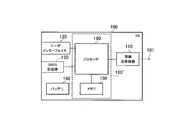
- FIG. 2 is a block diagram of the UE 100.
- the UE 100 includes an antenna 101, a radio transceiver 110, a user interface 120, a GNSS (Global Navigation Satellite System) receiver 130, a battery 140, a memory 150, and a processor 160.
- the memory 150 and the processor 160 constitute a control unit.
- the UE 100 may not have the GNSS receiver 130. Further, the memory 150 may be integrated with the processor 160, and this set (that is, a chip set) may be used as the processor 160 '.
- the antenna 101 and the wireless transceiver 110 are used for transmitting and receiving wireless signals.
- the antenna 101 includes a plurality of antenna elements.
- the radio transceiver 110 converts the baseband signal output from the processor 160 into a radio signal and transmits it from the antenna 101. Further, the radio transceiver 110 converts a radio signal received by the antenna 101 into a baseband signal and outputs the baseband signal to the processor 160.
- the user interface 120 is an interface with a user who owns the UE 100, and includes, for example, a display, a microphone, a speaker, and various buttons.
- the user interface 120 receives an operation from the user and outputs a signal indicating the content of the operation to the processor 160.
- the GNSS receiver 130 receives a GNSS signal and outputs the received signal to the processor 160 in order to obtain position information indicating the geographical position of the UE 100.
- the battery 140 stores power to be supplied to each block of the UE 100.
- the memory 150 stores a program executed by the processor 160 and information used for processing by the processor 160.
- the processor 160 includes a baseband processor that modulates / demodulates and encodes / decodes a baseband signal, and a CPU (Central Processing Unit) that executes programs stored in the memory 150 and performs various processes. .
- the processor 160 may further include a codec that performs encoding / decoding of an audio / video signal.
- the processor 160 executes various processes and various communication protocols described later.
- FIG. 3 is a block diagram of the eNB 200.
- the eNB 200 includes an antenna 201, a radio transceiver 210, a network interface 220, a memory 230, and a processor 240.
- the memory 230 and the processor 240 constitute a control unit.
- the antenna 201 and the wireless transceiver 210 are used for transmitting and receiving wireless signals.
- the antenna 201 includes a plurality of antenna elements.
- the wireless transceiver 210 converts the baseband signal output from the processor 240 into a wireless signal and transmits it from the antenna 201.
- the radio transceiver 210 converts a radio signal received by the antenna 201 into a baseband signal and outputs the baseband signal to the processor 240.
- the network interface 220 is connected to the neighboring eNB 200 via the X2 interface and is connected to the MME / S-GW 300 via the S1 interface.
- the network interface 220 is used for communication performed on the X2 interface and communication performed on the S1 interface.
- the memory 230 stores a program executed by the processor 240 and information used for processing by the processor 240.
- the processor 240 includes a baseband processor that performs modulation / demodulation and encoding / decoding of a baseband signal, and a CPU that executes programs stored in the memory 230 and performs various processes.
- the processor 240 executes various processes and various communication protocols described later.
- FIG. 4 is a protocol stack diagram of a radio interface in the LTE system.
- the radio interface protocol is divided into layers 1 to 3 of the OSI reference model, and layer 1 is a physical (PHY) layer.
- Layer 2 includes a MAC (Media Access Control) layer, an RLC (Radio Link Control) layer, and a PDCP (Packet Data Convergence Protocol) layer.
- Layer 3 includes an RRC (Radio Resource Control) layer.
- the physical layer performs encoding / decoding, modulation / demodulation, antenna mapping / demapping, and resource mapping / demapping.
- the physical layer provides a transmission service to an upper layer using a physical channel. Data is transmitted between the physical layer of the UE 100 and the physical layer of the eNB 200 via a physical channel.
- the MAC layer performs data priority control, retransmission processing by hybrid ARQ (HARQ), and the like. Data is transmitted via the transport channel between the MAC layer of the UE 100 and the MAC layer of the eNB 200.
- the MAC layer of the eNB 200 includes a MAC scheduler that determines an uplink / downlink transport format (transport block size, modulation / coding scheme, and the like) and an allocated resource block.
- the RLC layer transmits data to the RLC layer on the receiving side using the functions of the MAC layer and the physical layer. Data is transmitted between the RLC layer of the UE 100 and the RLC layer of the eNB 200 via a logical channel.
- the PDCP layer performs header compression / decompression and encryption / decryption.
- the RRC layer is defined only in the control plane. Control signals (RRC messages) for various settings are transmitted between the RRC layer of the UE 100 and the RRC layer of the eNB 200.
- the RRC layer controls the logical channel, the transport channel, and the physical channel according to establishment, re-establishment, and release of the radio bearer. If there is an RRC connection between the RRC of the UE 100 and the RRC of the eNB 200, the UE 100 is in a connected state, otherwise, the UE 100 is in an idle state.
- the NAS (Non-Access Stratum) layer located above the RRC layer performs session management and mobility management.
- FIG. 5 is a configuration diagram of a radio frame used in the LTE system.
- the LTE system uses OFDMA (Orthogonal Frequency Division Multiplexing Access) for the downlink and SC-FDMA (Single Carrier Division Multiple Access) for the uplink.
- OFDMA Orthogonal Frequency Division Multiplexing Access
- SC-FDMA Single Carrier Division Multiple Access
- the radio frame is composed of 10 subframes arranged in the time direction, and each subframe is composed of two slots arranged in the time direction.
- the length of each subframe is 1 ms, and the length of each slot is 0.5 ms.
- Each subframe includes a plurality of resource blocks (RB) in the frequency direction and includes a plurality of symbols in the time direction.
- a guard interval called a cyclic prefix (CP) is provided at the head of each symbol.
- the resource block includes a plurality of subcarriers in the frequency direction.
- a radio resource unit composed of one subcarrier and one symbol is called a resource element (RE).
- RE resource element
- frequency resources can be specified by resource blocks, and time resources can be specified by subframes (or slots).
- the section of the first few symbols of each subframe is a control region mainly used as a physical downlink control channel (PDCCH).
- the remaining section of each subframe is an area that can be used mainly as a physical downlink shared channel (PDSCH).
- PDSCH physical downlink shared channel
- CRS cell-specific reference signals
- both ends in the frequency direction in each subframe are control regions mainly used as a physical uplink control channel (PUCCH). Further, the central portion in the frequency direction in each subframe is an area that can be used mainly as a physical uplink shared channel (PUSCH). Further, a demodulation reference signal (DMRS) and a sounding reference signal (SRS) are arranged in each subframe.
- DMRS demodulation reference signal
- SRS sounding reference signal
- D2D communication Next, normal communication (cellular communication) of the LTE system and D2D communication will be compared and described.
- FIG. 6 shows a data path in cellular communication.
- a data path means a transfer path of user data (user plane).
- the data path of cellular communication goes through the network. Specifically, a data path passing through the eNB 200-1, the S-GW 300, and the eNB 200-2 is set.
- FIG. 7 shows a data path in D2D communication.
- a case where D2D communication is performed between the UE 100-1 that has established a connection with the eNB 200-1 and the UE 100-2 that has established a connection with the eNB 200-2 is illustrated.
- the UE 100-1 and the UE 100-2 form a D2D group.
- the D2D communication is started.
- the UE 100 has a function of discovering another UE 100 existing in the vicinity of the UE 100 (Discover). Further, the UE 100 has a (Discoverable) function that is discovered from other UEs 100.
- the data path of D2D communication does not go through the network. That is, direct radio communication is performed between UEs. As described above, if the UE 100-2 exists in the vicinity of the UE 100-1, the network traffic load and the battery consumption of the UE 100 are reduced by performing D2D communication between the UE 100-1 and the UE 100-2. The effect of doing etc. is acquired. In a special mode called “Locally Routed”, the data path does not pass through the S-GW 300 but passes through the eNB 200.
- D2D communication is performed in the frequency band of the LTE system.
- D2D communication is performed under the management of the network (eNB 200).
- eNB 200 There are mainly the following two methods for radio resource allocation in D2D communication.
- the first allocation method is a method by which the UE 100 can select a radio resource to be used for D2D communication.
- eNB200 transmits the information which shows the allocation candidate radio
- UE100 autonomously selects the radio
- the second allocation method is a method in which the eNB 200 determines radio resources to be used for D2D communication. That is, the UE 100 does not have a right to select a radio resource used for D2D communication. Specifically, eNB200 transmits the information which shows the radio
- the UE 100 transmits a search signal (Discovery signal) for searching for another UE 100 existing in the vicinity of the UE 100 before starting the D2D communication. Or UE100 transmits the search signal (Discoverable signal) for searching from other UE100, when desiring to start D2D communication.
- a search signal Discovery signal
- UE100 transmits the search signal (Discoverable signal) for searching from other UE100, when desiring to start D2D communication.
- 1st Embodiment demonstrates the case where UE100 transmits a Discovery signal.
- FIG. 8 is a diagram for explaining the discovery process.
- the UE 100-1 searching for a UE existing in the vicinity of itself transmits a Discovery signal in order to start D2D communication.
- the UE 100-2 attempts to receive the Discovery signal in order to start D2D communication.
- the UE 100-2 when the UE 100-2 receives the Discovery signal from the UE 100-1, the UE 100-2 discovers the UE 100-1, and transmits (returns) the Discovery response signal, which is a response signal to the Discovery signal, to the UE 100-1.
- the UE 100-1 discovers the UE 100-2 in response to receiving the Discovery response signal from the UE 100-2.
- the transmission of the Discovery response signal by the UE 100-2 is not essential and may be omitted.
- the UE 100-2 that has received the Discovery signal notifies the network of the result, and the UE 100-1 and the UE 100-2 are found to be mutually discovered by the network assistance.
- Discovery signal and the Discovery response signal are collectively referred to as “discovery signal”.
- the UE 100-1 and / or the UE 100-2 transmits a D2D communication request for starting D2D communication to the eNB 200.
- D2D communication is started under the management of the eNB 200.
- the discovery signal is transmitted and received within the frequency band assigned to the mobile communication system.
- the discovery signal may be transmitted and received using a radio resource that can be used for D2D communication within a frequency band assigned to the mobile communication system.
- the discovery signal may be transmitted / received within a frequency band assigned to the mobile communication system and using radio resources that cannot be used for D2D communication.
- discovery signals can be transmitted and received in the 1.5 GHz band, and D2D communication can be performed in the 2 GHz band.
- FIG. 9 is a diagram for explaining a communication environment in which a plurality of communication frequency bands exist.
- the eNB 200 manages three cells C1 to C3 corresponding to three communication frequency bands, and UEs 100a to 100c are accommodated in each cell.
- the cells C1 to C3 are cells that support D2D communication. Further, it is assumed that the UEs 100a to 100c are geographically close to each other.
- the UE 100a accommodated in the cell C1 transmits a Discovery signal in a communication frequency band corresponding to the cell C1 in order to start D2D communication.
- the UE 100b accommodated in the cell C2 tries to receive the Discovery signal in the communication frequency band corresponding to the cell C2 in order to start D2D communication.
- the UE 100a and the UE 100b cannot discover each other even though they are close to each other, and thus cannot start D2D communication.
- the eNB 200 transmits discovery resource information indicating radio resources to be used for transmission / reception of discovery signals (Discovery signal, Discovery response signal) to the UE 100a and the UE 100b.
- discovery signals Discovery signal, Discovery response signal
- Radio resources to be used for transmission / reception of discovery signals are referred to as “Discovery resources”, and discovery resource information is referred to as “Discovery resource information”.
- the transmission of Discovery resource information may be broadcast or unicast, but in the following, the case of transmission by broadcast will be mainly described.
- the eNB 200 includes Discovery resource information in a system information block (SIB) and transmits the information.
- SIB system information block
- the UE 100a and the UE 100b When the UE 100a and the UE 100b receive the Discovery resource information from the eNB 200, the UE 100a and the UE 100b transmit and receive a discovery signal (Discovery signal, Discovery response signal) using the Discovery resource indicated by the received Discovery resource information. As a result, the UE 100a and the UE 100b can transmit and receive the discovery signal normally and can discover each other, so that D2D communication can be started.
- a discovery signal Discovery signal, Discovery response signal
- FIG. 10 is a diagram for explaining Discovery resource information.
- the Discovery resource is provided in a specific resource block in a specific communication frequency band in the frequency direction. Further, the Discovery resource is provided in a specific symbol in a specific subframe in the time direction.
- the Discovery resource information is information indicating the Discovery resource.
- the Discovery resource information includes information indicating a frequency resource to be used for transmission / reception of a discovery signal.
- the frequency resource is a communication frequency band and / or a resource block included in the communication frequency band.
- the Discovery resource information includes information indicating a time resource to be used for transmission / reception of a discovery signal.
- the time resource is at least one of a radio frame, a subframe included in the radio frame, and a symbol included in the subframe.
- the eNB 200 may reserve different Discovery resources for the Discovery signal and the Discovery response signal.
- the Discovery resource information includes first information indicating a Discovery resource to be used for transmission / reception of the Discovery signal, and second information indicating a Discovery resource to be used for transmission / reception of the Discovery response signal.
- the eNB 200 may not use the secured Discovery resource for purposes other than transmission / reception of discovery signals (for example, a shared channel).
- the eNB 200 can dynamically change the Discovery resource according to the usage status of radio resources and / or the occurrence status of interference.
- the eNB 200 transmits Discovery resource information indicating the Discovery resource after the change.
- the UE 100 When dynamically changing the Discovery resource, the UE 100 that intends to start the D2D communication needs to constantly monitor the Discovery resource information and decode the received Discovery resource information in order to grasp the change of the Discovery resource.
- the Discovery resource information may include change information indicating that the Discovery resource has been changed.
- the UE 100 normally monitors and decodes the change information in the Discovery resource information, and decodes other information in the Discovery resource information only when the change information indicates “changed”.
- the eNB 200 may transmit the change information and other information in different system information blocks (SIB).
- SIB system information blocks
- FIG. 11 is an operation sequence diagram of the eNB 200 and the UE 100 according to the first embodiment.
- an operation example when the eNB 200 is operated in a plurality of communication frequency bands (multiband) will be described.
- step S101 the eNB 200 broadcasts Discovery resource information indicating Discovery resources included in the band A.
- UE100-1 and UE100-2 receive Discovery resource information from eNB200.
- step S102 the UE 100-1 transmits a Discovery signal by using the Discovery resource indicated by the Discovery resource information received in Step S101.
- the UE 100-2 receives the Discovery signal from the UE 100-1.
- step S103 the UE 100-2 transmits a Discovery response signal to the UE 100-1 in response to receiving the Discovery signal in step S102.
- the UE 100-1 receives the Discovery response signal from the UE 100-2.
- D2D communication is started when the operations in steps S102 and S103 are completed normally.
- the discovery process is continued without completing the operations in steps S102 and S103 will be described.
- step S104 the eNB 200 broadcasts Discovery resource information indicating Discovery resources included in the band B.
- UE100-1 and UE100-2 receive Discovery resource information from eNB200.
- step S105 the UE 100-1 transmits a Discovery signal using the Discovery resource indicated by the Discovery resource information received in Step S104.
- the UE 100-2 receives the Discovery signal from the UE 100-1.
- step S106 the UE 100-2 transmits a Discovery response signal to the UE 100-1 in response to receiving the Discovery signal in step S105.
- the UE 100-1 receives the Discovery response signal from the UE 100-2.
- D2D communication is started if the operations in steps S105 and S106 are completed normally. In the following, a case will be described in which the operations in steps S105 and S106 are not completed normally and the discovery process is continued.
- the eNB 200 determines to change the Discovery resource included in the band A to the band B.
- step S107 the eNB 200 broadcasts Discovery resource information indicating Discovery resources included in the band B related to the change.
- UE100-1 and UE100-2 receive Discovery resource information from eNB200.
- Step S108 the UE 100-1 transmits a Discovery signal using the Discovery resource indicated by the Discovery resource information received in Step S107.
- the UE 100-2 receives the Discovery signal from the UE 100-1.
- step S109 the UE 100-2 transmits a Discovery response signal to the UE 100-1 in response to receiving the Discovery signal in step S108.
- the UE 100-1 receives the Discovery response signal from the UE 100-2.
- the UE 100 can transmit and receive a discovery signal using an appropriate Discovery resource. Therefore, D2D communication can be appropriately controlled.
- the eNB 200 transmits Discovery resource information indicating the Discovery resource after the change. Thereby, the Discovery resource can be changed according to the situation.
- the Discovery resource information includes at least one of first information indicating a Discovery resource to be used for transmission / reception of a Discovery signal and second information indicating a Discovery resource to be used for transmission / reception of a Discovery response signal. Thereby, an individual Discovery resource can be designated for each of the Discovery signal and the Discovery response signal.
- the eNB 200 may not use the reserved Discovery resource for purposes other than the transmission / reception of the discovery signal when the Discovery resource is secured. Thereby, it can prevent that interference arises between transmission / reception of the signal for a discovery, and other communications (for example, cellular communications etc.).
- Discovery resource information includes information indicating frequency resources to be used for transmission / reception of discovery signals.
- the frequency resource is a communication frequency band and / or a resource block included in the communication frequency band.
- Discovery resource information includes information indicating a time resource to be used for transmission / reception of a discovery signal.
- the time resource is at least one of a radio frame, a subframe included in the radio frame, and a symbol included in the subframe.
- the eNB 200 may notify the Discovery eNB of the Discovery resource.
- the eNB 200 may directly notify the neighboring eNB on the X2 interface or indirectly notify on the S1 interface.
- the neighboring eNB 200 that has received such a notification can grasp the operation status of the Discovery resource in the eNB 200 that is the notification source.
- the base station (Outline of the second embodiment)
- the base station manages cells.
- the base station changes a radio resource amount to be secured as a discovery resource (Discovery resource) based on a parameter related to a user terminal in the cell.
- the base station changes the amount of radio resources to be reserved as the discovery resource by changing the period of the time resource to be reserved as the discovery resource.
- the period of the time resource secured as the discovery resource is set to an integral multiple of the shortest period shared between the cell and the neighboring cell.
- the parameter related to the user terminal (UE) in the cell is the number of user terminals located in the cell.
- the parameter related to the user terminal in the cell is the frequency of handover of the user terminal from the neighboring cell to the cell and / or the frequency of handover of the user terminal from the cell to the neighboring cell.
- the base station changes the amount of radio resources secured as the discovery resource, and transmits setting information for changing the transmission interval of the discovery signal to the user terminal in the cell.
- FIG. 12 is a diagram for explaining an operating environment according to the second embodiment.
- a plurality of eNBs 200 (eNB 200-1 to eNB 200-3) are installed.
- the eNB 200-1 manages the cell C1
- the eNB 200-2 manages the cell C2
- the eNB 200-3 manages the cell C3.
- the cells C1 to C3 are adjacent to each other.
- the number of UEs 100 located in the cell C1 is the largest, the cell C2 is the second largest, and the cell C3 is the smallest.
- “located” does not matter whether the UE 100 is in an idle state or a connected state.
- Discovery signal Discovery signal
- Discovery resources per UE are reduced. Therefore, it is preferable to increase the amount of Discovery resources for a cell having a large number of UEs 100 in the area.
- the number of UEs 100 entering and leaving the cell C1 is the largest, the cell C2 is the next largest, and the cell C3 is the smallest.
- the UE 100 entering / exiting the cell includes the UE 100 entering / exiting the cell due to the cell reselection of the UE 100 in the idle state and the UE 100 entering / exiting the cell due to the handover by the UE 100 in the connected state.
- a cell having a large number of UEs 100 entering and exiting can be regarded as a cell having many UEs 100 that move.
- D2D communication discovery signal (Discovery signal)
- Discovery signal D2D communication discovery signal
- the eNB 200 changes the amount of radio resources to be secured as Discovery resources based on the parameters related to the UE 100 in the own cell.
- the “UE 100 in the own cell” means “at least the UE 100 in the own cell”, and may be “UE 100 in the tracking area including the own cell”.
- the parameter related to the UE 100 in the own cell is the number of UEs 100 located in the own cell.
- the “number of UEs 100 in the own cell” is preferably the number of UEs 100 that transmit and receive a discovery signal in the own cell. It is assumed that the UE 100 that transmits and receives the discovery signal exchanges with the eNB 200 in order to transmit and receive the discovery signal. Therefore, eNB200 can change the radio
- the “number of UEs 100 in the own cell” may be the number of UEs 100 that support D2D communication in the own cell.
- the UE 100 notifies the eNB 200 of information related to whether or not it supports its own D2D communication.
- the eNB 200 increases the amount of radio resources to be secured as Discovery resources when the number of UEs 100 located in the own cell is large.
- the eNB 200 reduces the amount of radio resources to be secured as Discovery resources.
- the parameters related to the UE 100 in the own cell include the frequency of handover of the UE 100 from the neighboring cell to the own cell and / or the frequency of handover occurrence of the UE 100 from the own cell to the neighboring cell (hereinafter simply referred to as the UE 100). This is called “handover frequency”.
- handover frequency When the frequency of handover occurrence is high, the eNB 200 increases the amount of radio resources to be secured as Discovery resources. In contrast, the eNB 200 reduces the amount of radio resources to be secured as Discovery resources when the frequency of occurrence of handover is low.
- eNB200 transmits the setting information for changing the transmission interval of the signal for a discovery to UE100 in a cell while changing the radio
- the eNB 200 increases the amount of radio resources to be secured as Discovery resources, and transmits setting information for shortening the transmission interval of discovery signals to the UE 100 in the cell.
- the eNB 200 transmits the setting information for increasing the transmission interval of the discovery signal to the UE 100 in the cell while reducing the amount of radio resources to be secured as Discovery resources.
- the eNB 200 changes the radio resource amount to be secured as the Discovery resource by changing the period of the time resource to be secured as the Discovery resource.
- the period of the time resource to be secured as the Discovery resource is set to an integral multiple of the shortest period shared between the own cell and the neighboring cell. That is, the shortest cycle is a value common to each cell.
- FIG. 13 is a diagram for explaining a cycle of a time resource to be secured as a Discovery resource.
- the time resource constituting the Discovery resource is secured in units of subframes.
- eNB 200-1 reserves a subframe (hereinafter referred to as “Discovery subframe”) for transmitting and receiving a discovery signal in its own cell C1 at a cycle of 2 subframes.
- the 2 subframe period is the shortest period.
- the eNB 200-2 reserves Discovery subframes in the subcell C2 at a period of 4 subframes (that is, a period twice the shortest period).
- the eNB 200-3 reserves Discovery subframes in 8 subframe periods (that is, a period that is three times the shortest period) in its own cell C3.
- each of the eNB 200-1 to the eNB 200-3 when changing the Discovery subframe reserved in the own cell, the eNB 200 (adjacent eNB) that manages the neighboring cell and the UE 100 in the own cell Thus, the Discovery subframe after the change is notified.
- the notification of the discovery subframe may be a notification of a subframe number or a value indicating how many times the shortest cycle (hereinafter referred to as “period coefficient”) may be notified.
- periodic coefficient a value indicating how many times the shortest cycle
- the eNB 200-1 to the eNB 200-3 use the Discovery subframe reserved in the neighboring eNB for any of the following uses.
- the UE is also used as a Discovery resource in the own cell.
- FIG. 14 is a sequence diagram for explaining notification of a periodic coefficient to neighboring eNBs.
- notification from the eNB 200-1 to the neighboring eNB eNB 200-2 and eNB 200-3 will be described.
- the eNB 200-1 calculates a periodic coefficient.
- the calculation of the periodic coefficient may be performed periodically or may be performed on a trigger basis.
- the trigger may be that the number of UEs in a cell or in a tracking area exceeds or falls below a certain number, and the trigger occurrence frequency may be above or below a certain number.
- the eNB 200-1 changes the periodic coefficient.
- the eNB 200-1 transmits a Discovery cycle change notification indicating the changed cycle coefficient to the eNB 200-2 and the eNB 200-3.
- the Discovery cycle change notification may include a cell ID for identifying the cell of the eNB 200-1.
- the eNB 200-2 and the eNB 200-3 that have received the Discovery cycle change notification may transmit a response to the Discovery cycle change notification to the eNB 200-1 (Steps S203 and S205).
- FIG. 15 is a sequence diagram for explaining notification of a periodic coefficient to the UE in its own cell.
- notification from the eNB 200-1 to the UE (UE 100-1 and UE 100-2) in the own cell will be described.
- the eNB 200-1 calculates a periodic coefficient.
- the calculation of the periodic coefficient may be performed periodically or may be performed on a trigger basis.
- the trigger may be that the number of UEs in a cell or in a tracking area exceeds or falls below a certain number, and the trigger occurrence frequency may be above or below a certain number.
- the eNB 200-1 changes the periodic coefficient.
- the eNB 200-1 transmits a Discovery cycle change notification indicating the changed cycle coefficient to the UE 100-1 and the UE 100-2.
- the Discovery cycle change notification may be transmitted by broadcast or unicast.
- the UE 100-1 and the UE 100-2 that have received the Discovery cycle change notification may transmit a response to the Discovery cycle change notification to the eNB 200-1 (Steps S303 and S305).
- FIG. 16 is a flowchart for explaining a specific example 1 of the periodic coefficient calculation.
- a case where a periodic coefficient is calculated in eNB 200-1 will be described as an example.
- the eNB 200-1 determines whether there is a UE in its own cell.
- the UE in the own cell is preferably the UE 100 that performs D2D communication in the own cell or the UE 100 that transmits a discovery signal in the own cell.
- step S402 When there is no UE in the own cell (step S401: No), in step S402, the eNB 200-1 sets the periodic coefficient to zero. That is, the Discovery subframe is not secured.
- step S403 the eNB 200-1 determines the number of UEs in its own cell at the time of the previous cycle calculation (hereinafter referred to as “the number of previous UEs”) and It is determined whether or not the number of UEs in the own cell (hereinafter referred to as “the number of UEs this time”) matches at the time of the period calculation.
- step S404 the eNB 200-1 sets the periodic coefficient to the value at the previous period calculation.
- step S405 the eNB 200-1 determines the magnitude relationship between the previous UE number and the current UE number.
- steps S408 to S410 the current periodic coefficient is calculated and set in a range until the minimum periodic coefficient is reached so that the currentResource is larger than the previousResource.
- FIG. 17 is a flowchart for explaining a specific example 2 of the periodic coefficient calculation.
- a case where a periodic coefficient is calculated in eNB 200-1 will be described as an example.
- the eNB 200-1 determines whether or not there is a UE in its own cell.
- the UE in the own cell is preferably the UE 100 that performs D2D communication in the own cell or the UE 100 that transmits a discovery signal in the own cell. Or it is preferable that it is UE100 which supports D2D communication in an own cell.
- step S502 the eNB 200-1 sets the periodic coefficient to zero. That is, the Discovery subframe is not secured.
- step S501 When there is a UE in its own cell (step S501: Yes), in step S503, the eNB 200-1 determines whether there is a UE 100 that has handed over to an adjacent cell or a UE 100 that has been handed over to its own cell within a certain time until now. To do.
- step S504 If there is no UE 100 handed over to an adjacent cell or UE 100 handed over to its own cell within a certain time until now (step S503: No), in step S504, the eNB 200-1 sets the periodic coefficient to the maximum value.
- step S505 the eNB 200-1 performs handover to the adjacent cell within a certain time up to the present time. It is determined whether the result of dividing the maximum number of handovers by the number of UEs 100 that have been handed over or the number of UEs 100 handed over to the own cell (hereinafter referred to as “number of handovers”) is 1 or less.
- the maximum number of handovers is the number of handovers corresponding to the shortest cycle.
- step S506 When the result obtained by dividing the maximum number of handovers by the number of handovers is larger than 1 (step S505: No), in step S506, the eNB 200-1 cycles the value (rounded up) obtained by dividing the maximum number of handovers by the number of handovers. Calculate and set as a coefficient.
- step S507 the eNB 200-1 sets the periodic coefficient to the minimum value.
- the parameter related to the UE in the own cell is the number of UEs 100 located in the own cell. As a result, an optimal amount of Discovery resources can be secured for the number of UEs 100 located in the own cell.
- the parameter related to the UE in its own cell is the frequency of handover occurrence.
- the eNB200 transmits the setting information for changing the transmission interval of the signal for a discovery to UE100 in a cell while changing the radio
- the discovery signal can be transmitted and received at an optimum cycle with respect to the movement state of the UE in the own cell.
- the eNB 200 changes the amount of radio resources to be secured as the Discovery resource by changing the period of the time resource to be secured as the Discovery resource.
- the period of the time resource (that is, the subframe for Discovery) to be secured as the Discovery resource is set to an integer multiple of the shortest period shared between the own cell and the adjacent cell. As a result, the Discovery subframe can be synchronized between adjacent cells.
- the amount of radio resources to be secured as Discovery resources is changed in units of cells.
- the amount of radio resources is not limited to change in units of cells, but may be changed in units of tracking areas including the cells. When changing in units of tracking areas, it is easy to change in consideration of the situation of the UE 100 in an idle state.
- the radio resource amount to be secured as the Discovery resource is determined by the eNB 200.
- the radio resource amount is not limited to the case of being determined by the eNB 200, but is determined by a higher-level device (such as OAM 400 or MME 300) of the eNB 200.
- the radio resource amount to be secured by the Discovery resource may be changed by the eNB 200.
- the time resource constituting the Discovery resource is secured in units of subframes, but is not limited to being secured in units of subframes, and may be secured in units of radio frames or symbols.
- the present invention can appropriately control D2D communication, it is useful in the mobile communication field.
Abstract
Description
(第1実施形態の概要)
第1実施形態に係る移動通信システムは、直接的な端末間無線通信であるD2D通信をサポートする。移動通信システムは、前記D2D通信の通信相手端末の発見処理のための発見用信号を送受信するユーザ端末と、前記発見用信号の送受信に使用すべき無線リソースを示す発見用リソース情報を送信する基地局と、を有する。前記ユーザ端末は、前記基地局から前記発見用リソース情報を受信すると、当該受信した発見用リソース情報により示される無線リソースを使用して、前記発見用信号を送受信する。これにより、発見用信号の送受信に使用すべき無線リソースを基地局が指定できるので、ユーザ端末が適切な無線リソースを用いて発見用信号を送受信できる。したがって、D2D通信を適切に制御できる。
図1は、第1実施形態に係るLTEシステムの構成図である。
次に、LTEシステムの通常の通信(セルラ通信)とD2D通信とを比較して説明する。
UE100は、D2D通信を開始する前に、自身の近傍に存在する他のUE100を探索するための探索信号(Discovery信号)を送信する。或いは、UE100は、D2D通信の開始を望む場合に、他のUE100から探索されるための探索信号(Discoverable信号)を送信する。第1実施形態では、UE100がDiscovery信号を送信するケースについて説明する。
図8において、UE100-2は、UE100-1がどの無線リソースを使用してDiscovery信号を送信するのかを把握していなければ、当該Discovery信号を受信することは困難である。同様に、UE100-1は、UE100-2がどの無線リソースを使用してDiscovery応答信号を送信するのかを把握していなければ、当該Discovery応答信号を受信することは困難である。特に、複数の通信周波数帯(マルチバンド)が存在する通信環境下において、このような問題が顕著である。
第1実施形態によれば、DiscoveryリソースをeNB200が指定できるので、UE100が適切なDiscoveryリソースを用いて発見用信号を送受信できる。したがって、D2D通信を適切に制御できる。
eNB200は、Discoveryリソースを隣接eNBに通知してもよい。この場合、eNB200は、隣接eNBに対して、X2インターフェイス上で直接的に通知を行ってもよく、S1インターフェイス上で間接的に通知を行ってもよい。このような通知を受けた隣接eNB200は、通知元のeNB200におけるDiscoveryリソースの運用状況を把握できる。
次に、第2実施形態について、第1実施形態との相違点を主として説明する。第2実施形態は、システム構成については第1実施形態と同様である。
第2実施形態に係る基地局(eNB)は、セルを管理する。前記基地局は、前記セル内のユーザ端末に関するパラメータに基づいて、発見用リソース(Discoveryリソース)として確保する無線リソース量を変更する。
図12は、第2実施形態に係る動作環境を説明するための図である。
第2実施形態に係るeNB200は、自セル内UEに関するパラメータに基づいて、Discoveryリソースして確保する無線リソース量を変更する。これにより、Discoveryリソースして確保する無線リソース量を適応的に変更できる。
第2実施形態では、Discoveryリソースして確保する無線リソース量をセル単位で変更していたが、セル単位で変更する場合に限らず、当該セルを含むトラッキングエリア単位で変更してもよい。トラッキングエリア単位で変更する場合、アイドル状態のUE100の状況を加味して変更することが容易である。
Claims (16)
- 直接的な端末間無線通信であるD2D通信をサポートする移動通信システムであって、
前記D2D通信の通信相手端末の発見処理のための発見用信号を送受信するユーザ端末と、
前記発見用信号の送受信に使用すべき無線リソースである発見用リソースを示す発見用リソース情報を送信する基地局と、を有し、
前記ユーザ端末は、前記基地局から前記発見用リソース情報を受信すると、当該受信した発見用リソース情報により示される前記発見用リソースを使用して、前記発見用信号を送受信することを特徴とする移動通信システム。 - 前記基地局は、前記発見用リソースを変更する場合に、当該変更後の発見用リソースを示す発見用リソース情報を送信することを特徴とする請求項1に記載の移動通信システム。
- 前記発見用信号は、前記通信相手端末を探索するために送信される探索信号と、前記探索信号の受信に応じて返信される応答信号と、を含み、
前記発見用リソース情報は、前記探索信号の送受信に使用すべき無線リソースを示す第1の情報と、前記応答信号の送受信に使用すべき無線リソースを示す第2の情報と、を含むことを特徴とする請求項1に記載の移動通信システム。 - 前記基地局は、前記発見用リソースを確保した場合に、当該確保した発見用リソースを前記発見用信号の送受信以外の用途に使用しないことを特徴とする請求項1に記載の移動通信システム。
- 前記発見用リソース情報は、前記前記発見用リソースとして確保する周波数リソースを示す情報を含み、
前記周波数リソースは、通信周波数帯、及び/又は当該通信周波数帯に含まれるリソースブロックであることを特徴とする請求項1に記載の移動通信システム。 - 前記発見用リソース情報は、前記前記発見用リソースとして確保する時間リソースを示す情報を含み、
前記時間リソースは、無線フレーム、当該無線フレームに含まれるサブフレーム、及び当該サブフレームに含まれるシンボルのうち、少なくとも1つであることを特徴とする請求項1に記載の移動通信システム。 - 前記基地局は、前記発見用リソースを隣接基地局に通知することを特徴とする請求項1に記載の移動通信システム。
- 前記基地局は、セルを管理しており、
前記基地局は、前記セル内のユーザ端末に関するパラメータに基づいて、前記発見用リソースとして確保する無線リソース量を変更することを特徴とする請求項1に記載の移動通信システム。 - 前記基地局は、前記発見用リソースとして確保する時間リソースの周期を変更することにより、前記発見用リソースとして確保する無線リソース量を変更することを特徴とする請求項8に記載の移動通信システム。
- 前記発見用リソースとして確保する時間リソースの周期は、前記セル及び隣接セルで共有されている最短周期の整数倍に設定されることを特徴とする請求項9に記載の移動通信システム。
- 前記セル内のユーザ端末に関するパラメータとは、前記セルに在圏するユーザ端末の数であることを特徴とする請求項8に記載の移動通信システム。
- 前記セル内のユーザ端末に関するパラメータとは、隣接セルから前記セルへのユーザ端末のハンドオーバ発生頻度、及び/又は前記セルから隣接セルへのユーザ端末のハンドオーバ発生頻度であることを特徴とする請求項8に記載の移動通信システム。
- 前記基地局は、前記発見用リソースとして確保する無線リソース量を変更するとともに、前記発見用信号の送信間隔を変更するための設定情報を前記セル内のユーザ端末に送信することを特徴とする請求項12に記載の移動通信システム。
- 直接的な端末間無線通信であるD2D通信をサポートする移動通信システムにおいて、前記D2D通信の通信相手端末の発見処理のための発見用信号を送受信するユーザ端末を収容する基地局であって、
前記発見用信号の送受信に使用すべき無線リソースである発見用リソースを示す発見用リソース情報を前記ユーザ端末に送信するよう制御する制御部を有することを特徴とする基地局。 - 直接的な端末間無線通信であるD2D通信をサポートする移動通信システムにおいて、前記D2D通信の通信相手端末の発見処理のための発見用信号を送受信するユーザ端末であって、
前記発見用信号の送受信に使用すべき無線リソースである発見用リソースを示す発見用リソース情報を前記基地局から受信すると、当該受信した発見用リソース情報により示される前記発見用リソースを使用して、前記発見用信号を送受信するよう制御する制御部を有することを特徴とするユーザ端末。 - 直接的な端末間無線通信であるD2D通信をサポートする移動通信システムにおいて、前記D2D通信の通信相手端末の発見処理のための発見用信号を送受信するユーザ端末に備えられるプロセッサであって、
前記発見用信号の送受信に使用すべき無線リソースである発見用リソースを示す発見用リソース情報を前記ユーザ端末が前記基地局から受信すると、当該受信した発見用リソース情報により示される前記発見用リソースを使用して、前記発見用信号を送受信するための処理を行うことを特徴とするプロセッサ。
Priority Applications (5)
| Application Number | Priority Date | Filing Date | Title |
|---|---|---|---|
| EP13832312.6A EP2892258A4 (en) | 2012-08-29 | 2013-07-09 | MOBILE COMMUNICATION SYSTEM, BASE STATION, USER TERMINAL AND PROCESSOR |
| US14/424,002 US9485798B2 (en) | 2012-08-29 | 2013-07-09 | Mobile communication system, base station, user terminal, and processor |
| JP2014532867A JPWO2014034286A1 (ja) | 2012-08-29 | 2013-07-09 | 無線基地局及びプロセッサ |
| US15/198,142 US9801221B2 (en) | 2012-08-29 | 2016-06-30 | Mobile communication system, base station, user terminal, and processor |
| US15/789,358 US10004104B2 (en) | 2012-08-29 | 2017-10-20 | Mobile communication system, base station, user terminal, and processor |
Applications Claiming Priority (2)
| Application Number | Priority Date | Filing Date | Title |
|---|---|---|---|
| US201261694590P | 2012-08-29 | 2012-08-29 | |
| US61/694,590 | 2012-08-29 |
Related Child Applications (2)
| Application Number | Title | Priority Date | Filing Date |
|---|---|---|---|
| US14/424,002 A-371-Of-International US9485798B2 (en) | 2012-08-29 | 2013-07-09 | Mobile communication system, base station, user terminal, and processor |
| US15/198,142 Continuation US9801221B2 (en) | 2012-08-29 | 2016-06-30 | Mobile communication system, base station, user terminal, and processor |
Publications (1)
| Publication Number | Publication Date |
|---|---|
| WO2014034286A1 true WO2014034286A1 (ja) | 2014-03-06 |
Family
ID=50183107
Family Applications (1)
| Application Number | Title | Priority Date | Filing Date |
|---|---|---|---|
| PCT/JP2013/068791 WO2014034286A1 (ja) | 2012-08-29 | 2013-07-09 | 移動通信システム、基地局、ユーザ端末、及びプロセッサ |
Country Status (4)
| Country | Link |
|---|---|
| US (3) | US9485798B2 (ja) |
| EP (1) | EP2892258A4 (ja) |
| JP (6) | JPWO2014034286A1 (ja) |
| WO (1) | WO2014034286A1 (ja) |
Cited By (9)
| Publication number | Priority date | Publication date | Assignee | Title |
|---|---|---|---|---|
| CN106465091A (zh) * | 2014-05-09 | 2017-02-22 | 德国电信股份公司 | 用于改善装置间通信的方法、用户设备、系统、移动通信网络、程序和计算机程序产品 |
| KR20170020877A (ko) * | 2014-08-07 | 2017-02-24 | 엘지전자 주식회사 | 무선 통신 시스템에서 단말에 의해 수행되는 d2d(device-to-device) 동작 방법 및 상기 방법을 이용하는 단말 |
| JPWO2015194014A1 (ja) * | 2014-06-19 | 2017-04-20 | 富士通株式会社 | 無線通信システム、無線通信方法、無線機器、及び、無線基地局 |
| JP2017522774A (ja) * | 2014-05-27 | 2017-08-10 | エルジー エレクトロニクス インコーポレイティド | 無線通信システムにおける装置対装置端末のデータ伝送方法及び装置 |
| JP2017529760A (ja) * | 2014-08-07 | 2017-10-05 | アルカテル−ルーセント | セルラ送信におけるd2d帯域内干渉の影響を低減する方法 |
| EP3142421A4 (en) * | 2014-05-09 | 2018-01-17 | Kyocera Corporation | User terminal and base station |
| JP2018191326A (ja) * | 2012-08-29 | 2018-11-29 | 京セラ株式会社 | 無線基地局、ユーザ端末及びプロセッサ |
| US10383034B2 (en) | 2013-08-07 | 2019-08-13 | Samsung Electronics Co., Ltd. | Method and apparatus for transmitting and receiving resource allocation information in a wireless communication system |
| JP2019146256A (ja) * | 2014-03-31 | 2019-08-29 | 富士通コネクテッドテクノロジーズ株式会社 | 信号送信装置、及び通信システム |
Families Citing this family (9)
| Publication number | Priority date | Publication date | Assignee | Title |
|---|---|---|---|---|
| KR102113060B1 (ko) * | 2012-09-28 | 2020-05-20 | 삼성전자주식회사 | 와이파이 네트워크 환경에서 와이파이 다이렉트 연결을 설정하기 위한 방법 및 시스템 |
| JP6247022B2 (ja) * | 2013-05-20 | 2017-12-13 | 株式会社Nttドコモ | ユーザ装置、通信システム、及び無線リソース選択方法 |
| JP5973967B2 (ja) * | 2013-07-19 | 2016-08-23 | 株式会社Nttドコモ | ユーザ装置、基地局、発見信号受信方法、及び発見信号送信方法 |
| CN104349378B (zh) * | 2013-07-26 | 2019-06-14 | 中兴通讯股份有限公司 | 发现信号测量的方法、基站及终端 |
| WO2015053382A1 (ja) * | 2013-10-11 | 2015-04-16 | 京セラ株式会社 | 通信制御方法、ユーザ端末及び通信装置 |
| US10251160B2 (en) * | 2014-01-31 | 2019-04-02 | Lg Electronics Inc. | D2D operation method performed by terminal in wireless communication system and terminal using same |
| WO2016024247A1 (en) * | 2014-08-15 | 2016-02-18 | Telefonaktiebolaget L M Ericsson (Publ) | Configuring discovery signals |
| US9942742B2 (en) * | 2014-09-26 | 2018-04-10 | Nokia Solutions And Networks Oy | Signal transmission for proximity-based services wireless communications |
| US10225754B2 (en) * | 2015-12-16 | 2019-03-05 | Futurewei Technologies, Inc. | System and method for a hub device search |
Family Cites Families (14)
| Publication number | Priority date | Publication date | Assignee | Title |
|---|---|---|---|---|
| JPH10154969A (ja) | 1996-11-22 | 1998-06-09 | Sony Corp | 通信方法、基地局及び端末装置 |
| EP2277347A1 (en) * | 2008-05-15 | 2011-01-26 | Nokia Corporation | Methods, apparatuses and computer program products for providing coordination of device to device communication |
| US9485069B2 (en) * | 2010-04-15 | 2016-11-01 | Qualcomm Incorporated | Transmission and reception of proximity detection signal for peer discovery |
| US8812657B2 (en) * | 2010-04-15 | 2014-08-19 | Qualcomm Incorporated | Network-assisted peer discovery |
| US9288773B2 (en) | 2011-04-22 | 2016-03-15 | Qualcomm Incorporated | Methods and apparatus for controlling interference from peer discovery in WWAN |
| US9237434B2 (en) * | 2011-07-13 | 2016-01-12 | Qualcomm Incorporated | Network-assisted peer discovery with network coding |
| WO2013049959A1 (en) * | 2011-10-02 | 2013-04-11 | Renesas Mobile Corporation | Signaling for device-to-device wireless communication |
| GB2496153B (en) * | 2011-11-02 | 2014-07-02 | Broadcom Corp | Device-to-device communications |
| GB2498575A (en) * | 2012-01-20 | 2013-07-24 | Renesas Mobile Corp | Device-to-device discovery resource allocation for multiple cells in a device-to-device discovery area |
| EP2665321B1 (en) * | 2012-05-15 | 2017-03-22 | Telefonaktiebolaget LM Ericsson (publ) | Apparatus and method thereof for setting up device-to-device communication |
| US9084241B2 (en) | 2012-05-21 | 2015-07-14 | Qualcomm Incorporated | Methods and apparatus for determining available resources for D2D communications |
| JP6352255B2 (ja) * | 2012-07-05 | 2018-07-04 | エルジー エレクトロニクス インコーポレイティド | 無線通信システムにおいて端末間直接通信のための端末検出信号送信方法及びそのための装置 |
| EP2892258A4 (en) * | 2012-08-29 | 2016-04-20 | Kyocera Corp | MOBILE COMMUNICATION SYSTEM, BASE STATION, USER TERMINAL AND PROCESSOR |
| RU2629430C2 (ru) * | 2013-01-16 | 2017-08-29 | Интердиджитал Пэйтент Холдингз, Инк. | Генерация и прием сигнала обнаружения |
-
2013
- 2013-07-09 EP EP13832312.6A patent/EP2892258A4/en not_active Withdrawn
- 2013-07-09 WO PCT/JP2013/068791 patent/WO2014034286A1/ja active Application Filing
- 2013-07-09 JP JP2014532867A patent/JPWO2014034286A1/ja active Pending
- 2013-07-09 US US14/424,002 patent/US9485798B2/en active Active
-
2016
- 2016-04-11 JP JP2016079059A patent/JP2016174369A/ja active Pending
- 2016-06-30 US US15/198,142 patent/US9801221B2/en not_active Expired - Fee Related
- 2016-11-28 JP JP2016230402A patent/JP2017063482A/ja active Pending
-
2017
- 2017-10-20 US US15/789,358 patent/US10004104B2/en active Active
- 2017-12-19 JP JP2017242557A patent/JP6337194B2/ja not_active Expired - Fee Related
-
2018
- 2018-05-07 JP JP2018089490A patent/JP6382467B2/ja active Active
- 2018-08-01 JP JP2018144692A patent/JP6475885B2/ja not_active Expired - Fee Related
Non-Patent Citations (2)
| Title |
|---|
| QUALCOMM: "3GPP RAN Rel-12 & Beyond", 3GPP TSG RAN WORKSHOP ON REL-12 AND ONWARDS RWS-120007, 11 June 2012 (2012-06-11), XP055250279, Retrieved from the Internet <URL:http://www.3gpp.org/ftp/workshop/2012-06-11_12_RAN_REL12/Docs/RWS-120007.zip> [retrieved on 20130925] * |
| See also references of EP2892258A4 * |
Cited By (28)
| Publication number | Priority date | Publication date | Assignee | Title |
|---|---|---|---|---|
| JP2018191326A (ja) * | 2012-08-29 | 2018-11-29 | 京セラ株式会社 | 無線基地局、ユーザ端末及びプロセッサ |
| US10999782B2 (en) | 2013-08-07 | 2021-05-04 | Samsung Electronics Co., Ltd. | Method and apparatus for transmitting and receiving resource allocation information in a wireless communication system |
| US10383034B2 (en) | 2013-08-07 | 2019-08-13 | Samsung Electronics Co., Ltd. | Method and apparatus for transmitting and receiving resource allocation information in a wireless communication system |
| JP2019146256A (ja) * | 2014-03-31 | 2019-08-29 | 富士通コネクテッドテクノロジーズ株式会社 | 信号送信装置、及び通信システム |
| JP2017517964A (ja) * | 2014-05-09 | 2017-06-29 | ドイッチェ テレコム アーゲー | デバイス・ツー・デバイス通信を改善するための方法、改善されたデバイス・ツー・デバイス通信に適合されるユーザ装置、デバイス・ツー・デバイス通信を改善するためのシステム及び移動通信ネットワーク、プログラム及びコンピュータプログラム製品 |
| US10531271B2 (en) | 2014-05-09 | 2020-01-07 | Deutsche Telekom Ag | Improving device to device communication |
| EP3142421A4 (en) * | 2014-05-09 | 2018-01-17 | Kyocera Corporation | User terminal and base station |
| US9942743B2 (en) | 2014-05-09 | 2018-04-10 | Kyocera Corporation | User terminal and base station for a device to device proximity service |
| CN106465091B (zh) * | 2014-05-09 | 2020-05-26 | 德国电信股份公司 | 用于改善装置间通信的方法、用户设备、系统和移动通信网络 |
| CN106465091A (zh) * | 2014-05-09 | 2017-02-22 | 德国电信股份公司 | 用于改善装置间通信的方法、用户设备、系统、移动通信网络、程序和计算机程序产品 |
| JP2017522774A (ja) * | 2014-05-27 | 2017-08-10 | エルジー エレクトロニクス インコーポレイティド | 無線通信システムにおける装置対装置端末のデータ伝送方法及び装置 |
| JP2017522775A (ja) * | 2014-05-27 | 2017-08-10 | エルジー エレクトロニクス インコーポレイティド | 無線通信システムにおける装置対装置端末のデータ伝送方法及び装置 |
| US10368352B2 (en) | 2014-05-27 | 2019-07-30 | Lg Electronics Inc. | Data transmission method and apparatus by device to device terminal in wireless communication system |
| US10212703B2 (en) | 2014-05-27 | 2019-02-19 | Lg Electronics Inc. | Data transmission method and apparatus by device to device terminal in wireless communication system |
| US10334591B2 (en) | 2014-05-27 | 2019-06-25 | Lg Electronics Inc. | Data transmission method and apparatus by device terminal in wireless communication system |
| JPWO2015194014A1 (ja) * | 2014-06-19 | 2017-04-20 | 富士通株式会社 | 無線通信システム、無線通信方法、無線機器、及び、無線基地局 |
| US10327243B2 (en) | 2014-08-07 | 2019-06-18 | Lg Electronics Inc. | Device-to-device (D2D) operation method performed by terminal in wireless communications system and terminal using same |
| US10153936B2 (en) | 2014-08-07 | 2018-12-11 | Alcatel Lucent | Method of reducing impact of D2D in-band interference on cellular transmission |
| JP2017529760A (ja) * | 2014-08-07 | 2017-10-05 | アルカテル−ルーセント | セルラ送信におけるd2d帯域内干渉の影響を低減する方法 |
| JP2017527190A (ja) * | 2014-08-07 | 2017-09-14 | エルジー エレクトロニクス インコーポレイティド | 無線通信システムにおける端末により実行されるd2d動作方法及びその方法を利用する端末 |
| US10555306B2 (en) | 2014-08-07 | 2020-02-04 | Lg Electronics Inc. | Device-to-device (D2D) operation method performed by terminal in wireless communications system and terminal using same |
| KR102073902B1 (ko) | 2014-08-07 | 2020-02-05 | 엘지전자 주식회사 | 무선 통신 시스템에서 단말에 의해 수행되는 d2d(device-to-device) 동작 방법 및 상기 방법을 이용하는 단말 |
| CN106576334A (zh) * | 2014-08-07 | 2017-04-19 | Lg电子株式会社 | 在无线通信系统中由终端执行的装置对装置(d2d)操作方法和使用该方法的终端 |
| CN106576334B (zh) * | 2014-08-07 | 2020-06-30 | Lg电子株式会社 | 在无线通信系统中由终端执行的装置对装置(d2d)操作方法和使用该方法的终端 |
| EP3179802B1 (en) * | 2014-08-07 | 2020-07-08 | LG Electronics Inc. | Device-to-device (d2d) operation method performed by terminal in wireless communications system and terminal using same |
| EP3700275A1 (en) * | 2014-08-07 | 2020-08-26 | LG Electronics Inc. | Device-to-device (d2d) operation method performed by terminal in wireless communications system and terminal using same |
| US10986640B2 (en) | 2014-08-07 | 2021-04-20 | Lg Electronics Inc. | Device-to-device (D2D) operation method performed by terminal in wireless communications system and terminal using same |
| KR20170020877A (ko) * | 2014-08-07 | 2017-02-24 | 엘지전자 주식회사 | 무선 통신 시스템에서 단말에 의해 수행되는 d2d(device-to-device) 동작 방법 및 상기 방법을 이용하는 단말 |
Also Published As
| Publication number | Publication date |
|---|---|
| US9801221B2 (en) | 2017-10-24 |
| US10004104B2 (en) | 2018-06-19 |
| JP2018078614A (ja) | 2018-05-17 |
| US20160309316A1 (en) | 2016-10-20 |
| EP2892258A1 (en) | 2015-07-08 |
| JP2017063482A (ja) | 2017-03-30 |
| JP2018137820A (ja) | 2018-08-30 |
| US9485798B2 (en) | 2016-11-01 |
| JP2018191326A (ja) | 2018-11-29 |
| US20150223147A1 (en) | 2015-08-06 |
| US20180042063A1 (en) | 2018-02-08 |
| JP2016174369A (ja) | 2016-09-29 |
| JPWO2014034286A1 (ja) | 2016-08-08 |
| JP6337194B2 (ja) | 2018-06-06 |
| JP6382467B2 (ja) | 2018-08-29 |
| EP2892258A4 (en) | 2016-04-20 |
| JP6475885B2 (ja) | 2019-02-27 |
Similar Documents
| Publication | Publication Date | Title |
|---|---|---|
| JP6475885B2 (ja) | 無線基地局、ユーザ端末及びプロセッサ | |
| JP5981671B2 (ja) | 基地局、ユーザ端末及びプロセッサ | |
| JP6158899B2 (ja) | ユーザ端末、プロセッサ、及び基地局 | |
| JP5826937B2 (ja) | 移動通信システム、基地局、ユーザ端末、及びプロセッサ | |
| JP6174213B2 (ja) | ユーザ端末、プロセッサ及び基地局 | |
| WO2015064679A1 (ja) | 移動通信システム及びユーザ端末 | |
| WO2014017498A1 (ja) | 移動通信システム | |
| JP6147848B2 (ja) | 通信制御方法及びプロセッサ | |
| JP2015019177A (ja) | ネットワーク装置及び通信制御方法 | |
| JP6174141B2 (ja) | 通信制御方法及び基地局 | |
| JP6302129B1 (ja) | 基地局及びプロセッサ |
Legal Events
| Date | Code | Title | Description |
|---|---|---|---|
| 121 | Ep: the epo has been informed by wipo that ep was designated in this application |
Ref document number: 13832312 Country of ref document: EP Kind code of ref document: A1 |
|
| ENP | Entry into the national phase |
Ref document number: 2014532867 Country of ref document: JP Kind code of ref document: A |
|
| WWE | Wipo information: entry into national phase |
Ref document number: 14424002 Country of ref document: US |
|
| NENP | Non-entry into the national phase |
Ref country code: DE |
|
| WWE | Wipo information: entry into national phase |
Ref document number: 2013832312 Country of ref document: EP |