WO2014033972A1 - ガスタービン - Google Patents
ガスタービン Download PDFInfo
- Publication number
- WO2014033972A1 WO2014033972A1 PCT/JP2012/083983 JP2012083983W WO2014033972A1 WO 2014033972 A1 WO2014033972 A1 WO 2014033972A1 JP 2012083983 W JP2012083983 W JP 2012083983W WO 2014033972 A1 WO2014033972 A1 WO 2014033972A1
- Authority
- WO
- WIPO (PCT)
- Prior art keywords
- ring
- heat shield
- downstream
- upstream
- blade
- Prior art date
- Legal status (The legal status is an assumption and is not a legal conclusion. Google has not performed a legal analysis and makes no representation as to the accuracy of the status listed.)
- Ceased
Links
Images











Classifications
-
- F—MECHANICAL ENGINEERING; LIGHTING; HEATING; WEAPONS; BLASTING
- F01—MACHINES OR ENGINES IN GENERAL; ENGINE PLANTS IN GENERAL; STEAM ENGINES
- F01D—NON-POSITIVE DISPLACEMENT MACHINES OR ENGINES, e.g. STEAM TURBINES
- F01D25/00—Component parts, details, or accessories, not provided for in, or of interest apart from, other groups
- F01D25/24—Casings; Casing parts, e.g. diaphragms, casing fastenings
- F01D25/246—Fastening of diaphragms or stator-rings
-
- F—MECHANICAL ENGINEERING; LIGHTING; HEATING; WEAPONS; BLASTING
- F02—COMBUSTION ENGINES; HOT-GAS OR COMBUSTION-PRODUCT ENGINE PLANTS
- F02C—GAS-TURBINE PLANTS; AIR INTAKES FOR JET-PROPULSION PLANTS; CONTROLLING FUEL SUPPLY IN AIR-BREATHING JET-PROPULSION PLANTS
- F02C7/00—Features, components parts, details or accessories, not provided for in, or of interest apart form groups F02C1/00 - F02C6/00; Air intakes for jet-propulsion plants
- F02C7/20—Mounting or supporting of plant; Accommodating heat expansion or creep
-
- F—MECHANICAL ENGINEERING; LIGHTING; HEATING; WEAPONS; BLASTING
- F01—MACHINES OR ENGINES IN GENERAL; ENGINE PLANTS IN GENERAL; STEAM ENGINES
- F01D—NON-POSITIVE DISPLACEMENT MACHINES OR ENGINES, e.g. STEAM TURBINES
- F01D11/00—Preventing or minimising internal leakage of working-fluid, e.g. between stages
- F01D11/003—Preventing or minimising internal leakage of working-fluid, e.g. between stages by packing rings; Mechanical seals
-
- F—MECHANICAL ENGINEERING; LIGHTING; HEATING; WEAPONS; BLASTING
- F01—MACHINES OR ENGINES IN GENERAL; ENGINE PLANTS IN GENERAL; STEAM ENGINES
- F01D—NON-POSITIVE DISPLACEMENT MACHINES OR ENGINES, e.g. STEAM TURBINES
- F01D11/00—Preventing or minimising internal leakage of working-fluid, e.g. between stages
- F01D11/08—Preventing or minimising internal leakage of working-fluid, e.g. between stages for sealing space between rotor blade tips and stator
-
- F—MECHANICAL ENGINEERING; LIGHTING; HEATING; WEAPONS; BLASTING
- F01—MACHINES OR ENGINES IN GENERAL; ENGINE PLANTS IN GENERAL; STEAM ENGINES
- F01D—NON-POSITIVE DISPLACEMENT MACHINES OR ENGINES, e.g. STEAM TURBINES
- F01D25/00—Component parts, details, or accessories, not provided for in, or of interest apart from, other groups
- F01D25/08—Cooling; Heating; Heat-insulation
- F01D25/14—Casings modified therefor
- F01D25/145—Thermally insulated casings
-
- F—MECHANICAL ENGINEERING; LIGHTING; HEATING; WEAPONS; BLASTING
- F02—COMBUSTION ENGINES; HOT-GAS OR COMBUSTION-PRODUCT ENGINE PLANTS
- F02C—GAS-TURBINE PLANTS; AIR INTAKES FOR JET-PROPULSION PLANTS; CONTROLLING FUEL SUPPLY IN AIR-BREATHING JET-PROPULSION PLANTS
- F02C3/00—Gas-turbine plants characterised by the use of combustion products as the working fluid
- F02C3/04—Gas-turbine plants characterised by the use of combustion products as the working fluid having a turbine driving a compressor
-
- F—MECHANICAL ENGINEERING; LIGHTING; HEATING; WEAPONS; BLASTING
- F02—COMBUSTION ENGINES; HOT-GAS OR COMBUSTION-PRODUCT ENGINE PLANTS
- F02C—GAS-TURBINE PLANTS; AIR INTAKES FOR JET-PROPULSION PLANTS; CONTROLLING FUEL SUPPLY IN AIR-BREATHING JET-PROPULSION PLANTS
- F02C7/00—Features, components parts, details or accessories, not provided for in, or of interest apart form groups F02C1/00 - F02C6/00; Air intakes for jet-propulsion plants
-
- F—MECHANICAL ENGINEERING; LIGHTING; HEATING; WEAPONS; BLASTING
- F02—COMBUSTION ENGINES; HOT-GAS OR COMBUSTION-PRODUCT ENGINE PLANTS
- F02C—GAS-TURBINE PLANTS; AIR INTAKES FOR JET-PROPULSION PLANTS; CONTROLLING FUEL SUPPLY IN AIR-BREATHING JET-PROPULSION PLANTS
- F02C7/00—Features, components parts, details or accessories, not provided for in, or of interest apart form groups F02C1/00 - F02C6/00; Air intakes for jet-propulsion plants
- F02C7/28—Arrangement of seals
-
- F—MECHANICAL ENGINEERING; LIGHTING; HEATING; WEAPONS; BLASTING
- F01—MACHINES OR ENGINES IN GENERAL; ENGINE PLANTS IN GENERAL; STEAM ENGINES
- F01D—NON-POSITIVE DISPLACEMENT MACHINES OR ENGINES, e.g. STEAM TURBINES
- F01D1/00—Non-positive-displacement machines or engines, e.g. steam turbines
- F01D1/02—Non-positive-displacement machines or engines, e.g. steam turbines with stationary working-fluid guiding means and bladed or like rotor, e.g. multi-bladed impulse steam turbines
-
- F—MECHANICAL ENGINEERING; LIGHTING; HEATING; WEAPONS; BLASTING
- F01—MACHINES OR ENGINES IN GENERAL; ENGINE PLANTS IN GENERAL; STEAM ENGINES
- F01D—NON-POSITIVE DISPLACEMENT MACHINES OR ENGINES, e.g. STEAM TURBINES
- F01D25/00—Component parts, details, or accessories, not provided for in, or of interest apart from, other groups
- F01D25/24—Casings; Casing parts, e.g. diaphragms, casing fastenings
-
- F—MECHANICAL ENGINEERING; LIGHTING; HEATING; WEAPONS; BLASTING
- F01—MACHINES OR ENGINES IN GENERAL; ENGINE PLANTS IN GENERAL; STEAM ENGINES
- F01D—NON-POSITIVE DISPLACEMENT MACHINES OR ENGINES, e.g. STEAM TURBINES
- F01D25/00—Component parts, details, or accessories, not provided for in, or of interest apart from, other groups
- F01D25/28—Supporting or mounting arrangements, e.g. for turbine casing
-
- F—MECHANICAL ENGINEERING; LIGHTING; HEATING; WEAPONS; BLASTING
- F05—INDEXING SCHEMES RELATING TO ENGINES OR PUMPS IN VARIOUS SUBCLASSES OF CLASSES F01-F04
- F05D—INDEXING SCHEME FOR ASPECTS RELATING TO NON-POSITIVE-DISPLACEMENT MACHINES OR ENGINES, GAS-TURBINES OR JET-PROPULSION PLANTS
- F05D2240/00—Components
- F05D2240/10—Stators
- F05D2240/11—Shroud seal segments
-
- F—MECHANICAL ENGINEERING; LIGHTING; HEATING; WEAPONS; BLASTING
- F05—INDEXING SCHEMES RELATING TO ENGINES OR PUMPS IN VARIOUS SUBCLASSES OF CLASSES F01-F04
- F05D—INDEXING SCHEME FOR ASPECTS RELATING TO NON-POSITIVE-DISPLACEMENT MACHINES OR ENGINES, GAS-TURBINES OR JET-PROPULSION PLANTS
- F05D2240/00—Components
- F05D2240/10—Stators
- F05D2240/15—Heat shield
-
- F—MECHANICAL ENGINEERING; LIGHTING; HEATING; WEAPONS; BLASTING
- F05—INDEXING SCHEMES RELATING TO ENGINES OR PUMPS IN VARIOUS SUBCLASSES OF CLASSES F01-F04
- F05D—INDEXING SCHEME FOR ASPECTS RELATING TO NON-POSITIVE-DISPLACEMENT MACHINES OR ENGINES, GAS-TURBINES OR JET-PROPULSION PLANTS
- F05D2240/00—Components
- F05D2240/55—Seals
-
- F—MECHANICAL ENGINEERING; LIGHTING; HEATING; WEAPONS; BLASTING
- F05—INDEXING SCHEMES RELATING TO ENGINES OR PUMPS IN VARIOUS SUBCLASSES OF CLASSES F01-F04
- F05D—INDEXING SCHEME FOR ASPECTS RELATING TO NON-POSITIVE-DISPLACEMENT MACHINES OR ENGINES, GAS-TURBINES OR JET-PROPULSION PLANTS
- F05D2240/00—Components
- F05D2240/55—Seals
- F05D2240/58—Piston ring seals
- F05D2240/581—Double or plural piston ring arrangements, i.e. two or more piston rings
Definitions
- the present invention relates to a rotor and a gas turbine including a casing covering the rotor, and more particularly to a structure of a casing of the gas turbine.
- the gas turbine is disposed on the upstream side of each of a rotor body that rotates about a rotation axis, a rotor having a plurality of blade stages that are fixed to the rotor body in an axial direction, and a plurality of blade stages.
- the structure of the gas turbine casing is described in Patent Document 1 below.
- the casing includes a plurality of blade rings that form a ring around the rotation axis. Each blade ring covers one blade stage and a stationary blade stage disposed upstream of the blade stage.
- the casing further has an annular shape around the rotation axis.
- the casing is an inner periphery side of the blade ring and an outer periphery side of the moving blade, and has a plurality of divided rings arranged between the plurality of stationary blade stages, and has an annular shape around the rotation axis, A heat shield ring for attaching the stationary blade and the split ring to the inner peripheral side of the blade ring.
- the downstream side portion of the outer shroud of the plurality of stator blades constituting the first stator blade stage is attached to the first stage blade ring via the first heat shield ring arranged on the downstream side thereof.
- the split ring arranged on the downstream side of the first stator blade stage has its upstream side part attached to the first stage blade ring via the first heat shield ring, and its downstream side part is the second side. It is attached to a heat shield ring.
- a fixing ring is disposed as a pressing member that pushes the second heat shield ring upstream.
- the fixing ring is fixed to the downstream end of the first stage blade ring by a bolt.
- a heat shield ring for example, the first stator blade and the second stator blade disposed near the center in the axial direction of the integrated blade ring.
- the heat shield ring is assembled from the axial direction or the circumferential direction. Is difficult to fix to the wing ring.
- an object of the present invention is to provide a gas turbine that can ensure assemblability of a casing in which a plurality of blade ring parts are integrated.
- the gas turbine according to the invention for solving the above problems is A rotor body that rotates about a rotation axis, a rotor having a plurality of blade stages that are fixed to the rotor body along the axial direction in which the rotation axis extends, and upstream of each of the plurality of blade stages A plurality of stationary blade stages arranged on the side, and a casing that covers the rotor and has the plurality of stationary blade stages attached to the inner peripheral side,
- the casing has an annular shape around the rotation axis, and a plurality of blade ring portions covering one of the blade stages and one of the stationary blade stages, and an annular shape around the rotation axis,
- a plurality of heat shield rings for attaching the split ring, and a gas turbine comprising: The two
- the casing further includes: A pressing member disposed on the upstream side of the predetermined heat shield ring, attached to the blade ring portion, and pressing at least one pressed member of the predetermined heat shield ring and the upstream member to the downstream side; It has.
- the sealing performance of the packing is maintained by pushing the predetermined heat shield ring and the upstream member or the downstream member in the axial direction.
- the casing has a downstream side wall that extends further radially inward from the outer peripheral surface of the predetermined heat shield ring among the pressing member, the predetermined heat shield ring, and the blade ring portion from the upstream side in the axial direction toward the downstream side. And a structure in which the predetermined heat shield ring is sandwiched between the pressing member and the downstream side wall from the axial direction.
- the predetermined heat shield ring is sandwiched between the pressing member and the downstream side wall from the upstream side in the axial direction, the predetermined heat shield ring is pressed to the downstream side in the axial direction by the pressing member, and the predetermined heat shield ring is pressed against the blade ring portion. Therefore, the packing inserted between the predetermined heat shield ring and the upstream member or the downstream member can be compressed. Further, since the position of the predetermined heat shield ring in the axial direction is fixed, the gas turbine can be stably operated.
- the blade ring portion includes an upstream side wall adjacent to the upstream side in the axial direction of the predetermined heat shield ring and extending further radially inward from the outer peripheral surface of the predetermined heat shield ring, and the pressing member is provided on the upstream side wall.
- a through-groove that penetrates in the axial direction may be provided.
- the pressing member can be inserted from the upstream side in the axial direction through the through groove provided in the upstream side wall and pressed against the heat shield ring. Accordingly, the pressing member can be easily attached in the axial direction, the heat shield ring can be pressed against the downstream side wall from the upstream side, and the sealing performance of the packing can be maintained.
- the casing has an annular space on the inner peripheral side of the blade ring portion in the axial direction of the predetermined heat shield ring, and with an outer peripheral surface of the predetermined heat shield ring as an upper surface and a radially inner space. May be formed.
- the predetermined heat shield ring is provided.
- the thermal ring and the pressing member can be easily attached from the axial direction.
- the predetermined heat shield ring is formed with a guide portion in which the pressing member disposed on the upstream side of the predetermined heat shield ring is slidable in the radial direction, and on the inner peripheral side of the blade ring portion.
- a heat shield ring groove that is recessed toward the radially outer side and into which the predetermined heat shield ring enters and the pressing member enters is formed, The pressing member may be inserted into the heat shield ring groove from the radially inner side and attached to the blade ring portion.
- the pressing member is formed with a guide projection that protrudes axially downstream and engages with the guide portion of the predetermined heat shield ring, and is a radially outer portion of the predetermined heat shield ring.
- the dimension of the top thickness in the radial direction of the attached portion that enters the heat shield ring groove is at least the axial length of the guide protrusion than the dimension of the maximum groove width in the axial direction of the heat shield ring groove. It may be short.
- the predetermined heat shield Since the ring can be attached and detached from the axial direction, the packing between the predetermined heat shield ring and the upstream member or the downstream member can be inserted from the axial direction, and there is no possibility of damaging the surface of the packing during insertion.
- an inclined surface that gradually goes downstream as it goes radially outward may be formed on the upstream side wall of the heat shield ring groove.
- the pressing member in the process of pushing the pressing member into the heat shield ring groove, the pressing member can be moved downstream while moving radially outward by the inclined surface as the moving guide portion.
- the pressing force against the ring is further increased, and the sealing performance of the packing is further improved.
- the predetermined heat shield ring has a plurality of heat shield pieces, and the plurality of heat shield pieces constitutes the predetermined heat shield ring by forming a ring in a circumferential direction,
- Each of the plurality of heat shielding pieces may be provided with a circumferentially facing surface that faces the circumferentially facing surface of the pressing member and restricts relative movement of the pressing member in the circumferential direction. Good.
- the heat shield piece is positioned in the circumferential direction by fixing the pressing member to the blade ring portion (combined blade ring). be able to.
- the upstream member has a plurality of upstream member pieces, the plurality of upstream member pieces form a ring in a circumferential direction, and the plurality of upstream member pieces include:
- Each of the pressing members may be opposed to a surface facing the circumferential direction, and a circumferentially opposed surface that restricts relative movement of the pressing member in the circumferential direction may be formed.
- the upstream member piece since the upstream member piece is restricted from moving in the circumferential direction with respect to the pressing member, the upstream member piece can be positioned in the circumferential direction by fixing the pressing member to the blade ring portion.
- the upstream member has a plurality of upstream member pieces, and the plurality of upstream member pieces form a ring side by side in the circumferential direction, and the upstream side with respect to the predetermined heat shield ring
- a circumferential restriction member for restricting relative movement of the member piece in the circumferential direction, and the predetermined heat shield ring and the upstream member piece include different portions of the circumferential restriction member, respectively;
- a recess that restricts relative movement of the restricting member in the circumferential direction may be formed.
- the circumferential member can be positioned in the circumferential direction with respect to the predetermined heat shield ring by inserting the circumferential direction regulating member into the concave portion of the predetermined heat shield ring and the concave portion of the upstream member piece.
- the downstream member has a plurality of downstream member pieces, and the plurality of downstream member pieces form an annular shape along a circumferential direction, and the downstream member with respect to the blade ring portion A circumferential-direction regulating member that regulates relative movement of the piece in the circumferential direction; different portions of the circumferential-direction regulating member enter the blade ring portion and the downstream-side member piece, respectively.
- a recess for restricting relative movement in the circumferential direction may be formed.
- the circumferential member can be positioned in the circumferential direction with respect to the blade ring portion by inserting the circumferential direction regulating member into the recessed portion of the blade ring portion and the recessed portion of the downstream member piece.
- the pressing member includes a bolt head and a bolt having one end portion fixed to the bolt head portion and a shaft portion in which a male screw is formed at least on the other end side. Attached to the ring portion, the pressing member, the blade ring portion, and the predetermined heat shield ring are each formed in a through-hole through which the shaft portion of the bolt enters, penetrating in the axial direction and communicating with each other.
- a female screw into which the male screw of the bolt is screwed may be formed on an inner peripheral surface of one of the pressing member and the blade ring portion.
- a pressing member is screwed into a female screw as a moving guide portion formed on the inner peripheral surface of one of the pressing member and the blade ring portion, thereby fixing the pressing member.
- the pressing member and the predetermined heat shield ring can be fixed to the united blade ring (blade ring portion) while moving the downstream side.
- the pressing member includes a bolt head and a bolt having one end portion fixed to the bolt head portion and a shaft portion in which a male screw is formed at least on the other end side. It may be attached to the ring portion, and the shaft portion of the bolt may engage with the pressing member and the blade ring portion.
- the packing between the predetermined heat shield ring and the downstream member or upstream member is elastically deformed in the axial direction, and the predetermined shield.
- the space between the thermal ring and the downstream member or the upstream member is sealed. Therefore, in the gas turbine, since it is possible to save the trouble of elastically deforming the packing in the axial direction, the gas turbine can be easily assembled.
- a plurality of first stator blades constituting a first stator blade stage among a plurality of stator blade stages are attached to the first blade ring part of the two or more blade ring parts.
- the second blade ring portion disposed on the downstream side of the first blade ring portion includes a plurality of second static blades constituting a second stator blade stage disposed on the downstream side of the first stator blade step. Wings are attached,
- the predetermined heat shield ring includes, as a second blade ring portion, a downstream side portion of a first divided ring disposed between the first stator blade stage and the second stator blade stage among the plurality of split rings.
- a second upstream heat shield ring for attaching an upstream side portion of the outer shroud of the second stationary blade to the second blade ring portion, wherein the upstream member is the first split ring, and the downstream side
- the side member may be the second stationary blade stage.
- the predetermined heat shield ring attaches to the second blade ring portion an upstream side portion of a second divided ring disposed on the downstream side of the second stationary blade stage among the plurality of divided rings
- the second stationary blade includes a second downstream heat shield ring that attaches the downstream side portion in the outer shroud of the second stationary blade to the second blade ring portion, the upstream member is the second stationary blade stage, and the downstream member is
- the second split ring may be used.
- the predetermined heat shield ring attaches the upstream side portion of the first split ring to the first blade ring portion and attaches the downstream side portion of the outer shroud of the first stationary blade to the first blade ring portion.
- a first downstream side heat shield ring may be included, the upstream side member may be the first stationary blade stage, and the downstream side member may be the first split ring.
- the casing can be easily assembled even if it is a united blade ring.
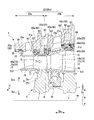
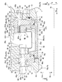
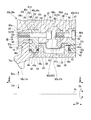
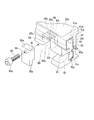
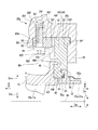
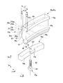
- FIG. 12 It is a disassembled perspective view around the pressing member in the first embodiment according to the present invention. It is principal part sectional drawing of the ga turbine in 2nd embodiment which concerns on this invention. It is the XII section enlarged view in FIG. It is an enlarged view around the 1st downstream attachment part which is the left side part in FIG. FIG. 13 is an enlarged view around a second upstream attachment portion that is a right side portion in FIG. 12. It is a disassembled perspective view of the 1st downstream pressing member and 1st downstream heat insulation piece in 2nd embodiment which concerns on this invention. It is a disassembled perspective view of the 2nd downstream pressing member and 2nd downstream heat insulation piece in 2nd embodiment which concerns on this invention. It is a XVII arrow directional view in FIG. It is a XVIII arrow directional view in FIG.
- the gas turbine of the present embodiment generates a combustion gas by compressing outside air to generate compressed air and mixing the fuel from the fuel supply source with the compressed air and burning it.
- the turbine 3 includes a casing 4 and a rotor 5 that rotates in the casing 4.
- the rotor 5 is connected to a generator (not shown) that generates electricity by the rotation of the rotor 5.
- the direction in which the rotation axis Ar serving as the rotation center of the rotor 5 extends is defined as the axial direction Da.
- a side closer to the rotational axis Ar is defined as a radially inner side Dri
- a side away from the rotational axis Ar is defined as a radially outer side Dro.
- the upstream side in the axial direction Da and the downstream side in the axial direction Da of the flow of the combustion gas are simply referred to as the upstream side and the downstream side.
- the rotor 5 includes a rotor body 6 that extends in the axial direction Da around the rotation axis Ar, and a plurality of blade stages 8 that are fixed to the rotor body 6 side by side in the axial direction Da.
- Each blade stage 8 has a plurality of blades 9 arranged in the circumferential direction Dc with respect to the rotation axis Ar.
- the rotor body 6 has a rotor disk 7 to which a plurality of blades 9 constituting the blade stage 8 are fixed for each blade stage 8.
- the rotor disks 7 for the respective rotor blade stages 8 are connected to each other in the axial direction Da.
- a plurality of stationary blade stages 10 arranged in the axial direction Da are fixed to the inner peripheral side of the casing 4.
- Each stationary blade stage 10 is arranged upstream of any one of the blade stages 8.
- Each stationary blade stage 10 has a plurality of stationary blades 11 arranged in the circumferential direction Dc with respect to the rotation axis Ar.
- the casing 4 includes a blade ring portion 20, a split ring 30, a heat shield ring 40, a pressing member 50, a bolt 60, and a shielding plate 90.
- the blade ring portion 20 is a member formed in an annular shape so as to cover the stationary blade 11 and the moving blade 9 of each stage.
- the split ring 30 is a member arranged in an annular shape between the plurality of stationary blade stages 10 on the inner peripheral side of the blade ring portion 20 and on the outer peripheral side of the moving blade 9.
- the heat shield ring 40 is a member formed in an annular shape for attaching the stationary blade 11 and the split ring 30 to the blade ring portion 20.
- the pressing member 50 is a member that pushes the heat shield ring 40 to the downstream side, and fixes the pressing member 50 to the blade ring portion 20 with a bolt (fixing tool) 60.
- the shielding plate 90 is disposed on the outer peripheral side of the split ring 30 and on the inner peripheral side of the blade ring portion 20.
- the casing 4 includes an annular casing (not shown) that covers the outer periphery of the blade ring portion 20.
- Each stationary blade 11 is provided on a stationary blade body 12 extending in the radial direction Dr, an outer shroud 13 provided on a radially outer side Dro of the stationary blade body 12, and a radially inner side Dri of the stationary blade body 12. And an inner shroud 18.
- the outer shroud 13 has an upstream leg 14 (FIG. 3) extending from the upstream side to the radially outer side Dro and a downstream leg 16 extending from the downstream side to the radially outer side Dro.
- An upstream protrusion 15 protruding toward the upstream side is formed on the radially outer end of the upstream leg 14.
- a downstream protrusion 17 that protrudes toward the downstream side is formed at the radially outer end of the downstream leg 16.
- Each moving blade 9 (FIG. 2) is provided on a moving blade main body 9x extending in the radial direction Dr, a platform 9y provided on the radial inner side Dri of the moving blade main body 9x, and a radial inner side Dri of the platform 9y.
- a blade root (not shown).
- the blade 9 has a blade root embedded in the rotor disk 7 and is fixed to the rotor disk 7.
- the high-temperature and high-pressure combustion gas G from the combustor 2 is provided. Constitutes a combustion gas flow path P through which the gas flows.
- the plurality of first stator blades 11 a constituting the most upstream first stator blade stage 10 a among the plurality of stator blade stages 10 are attached to the first blade ring part 20 a of the plurality of blade ring parts 20. .
- the plurality of second stator blades 11b constituting the second stator blade stage 10b disposed on the downstream side of the first stator blade stage 10a is attached to the second blade ring part 20b of the plurality of blade ring parts 20. It has been.
- the first blade ring portion 20a and the second blade ring portion 20b are integrally formed to form a combined blade ring 20x (blade ring portion 20).
- the blade ring portion 20 includes a plurality of first stator blades 11a constituting the first stator blade stage 10a, a plurality of second stator blades 11b constituting the second stator blade stage 10b, and a first stator blade stage 10a and A first split ring 30a disposed between the second stator blade stage 10b and a second split ring 30b disposed on the downstream side of the second stator blade stage 10b are attached. Further, the blade ring portion 20 includes a fixed block 49, a first downstream side heat shield ring 40a, a second upstream side heat shield ring 40b, a second downstream side heat shield ring 40c, and a third heat shield ring 40d.
- the fixed block 49 is a member for attaching the upstream side portion of the outer shroud 13 of the first stationary blade 11 a to the blade ring portion 20.
- the first downstream heat shield ring 40 a is a member for attaching the downstream side portion of the outer shroud 13 of the first stationary blade 11 a and the upstream side portion of the first split ring 30 a to the blade ring portion 20.
- the second upstream side heat shield ring 40 b is a member for attaching the downstream side portion of the first split ring 30 a and the upstream side portion of the outer shroud 13 of the second stationary blade 11 b to the blade ring portion 20.
- the second downstream side heat shield ring 40c is a member for attaching the downstream side portion of the outer shroud 13 of the second stationary blade 11b and the upstream side portion of the second split ring 30b to the blade ring portion 20.
- the third heat shield ring 40d is a member for attaching the downstream side portion of the second split ring 30b to the blade ring portion 20.
- these heat shield rings 40 are used.
- the above-described pressing member 50 that pushes the ring to the downstream side and the bolt 60 as a fixing tool for fixing the pressing member 50 to the blade ring portion 20 are used.
- a first upstream attachment portion 21e to which a fixing block 49 for the first stationary blade 11a is attached, a first downstream heat shield ring 40a, and a second A first downstream attachment portion 21a to which the one downstream pressing member 50a is attached is formed.
- a second upstream attachment portion 21b to which the second upstream heat shield ring 40b and the second upstream pressing member 50b are attached A second downstream attachment portion 21c to which the downstream heat shield ring 40c and the second downstream pressing member 50c are attached, and a third attachment portion 21d to which the third heat shield ring 40d and the third pressing member 50d are attached are formed.
- the first downstream attachment portion 21a, the second upstream attachment portion 21b, the second downstream attachment portion 21c, and the third attachment portion 21d all protrude from the blade ring portion 20 toward the radially inner side Dri.
- the respective attachment portions are, from the upstream side toward the downstream side, the first upstream attachment portion 21e, the first downstream attachment portion 21a, the second upstream attachment portion 21b, the second downstream attachment portion 21c, and the third. They are arranged in the order of the attachment portion 21d.
- the first downstream attachment portion 21 a, the second upstream attachment portion 21 b, and the second downstream attachment portion 21 c are each provided with a heat shield ring 40 interposed therebetween.
- Convex upstream side wall 23 and downstream side wall 25 that extend from the blade ring part 20 toward the radially inner side Dri from the outer peripheral surface of the heat shield ring 40 are arranged adjacent to 40 on the upstream side and downstream side in the axial direction.
- the upstream side wall 23 and the downstream side wall 25 are annular protrusions extending from the blade ring portion 20 to the radially inner side Dri.
- a heat shield ring 40 is inserted in the circumferential direction Dc into a heat shield ring space formed between the two. That is, the blade ring portion 20 has a structure in which each heat shield ring 40 is sandwiched between the upstream side wall 23 and the downstream side wall 25 from the axial direction. Further, the outer peripheral surface of each heat shield ring 40 inserted in the circumferential direction Dc toward the radially outer side Dro is in contact with the inner peripheral side of the blade ring portion 20. An inner peripheral surface facing the radially inner side Dri of the blade ring portion 20 forms a heat shield ring groove 22 in contact with the outer peripheral surface of each heat shield ring 40.
- Each divided ring 30 including the first divided ring 30a and the second divided ring 30b has a plurality of divided pieces 31 (FIG. 3).
- the plurality of split pieces 31 form a split ring 30 by forming a ring along the circumferential direction Dc with respect to the rotation axis Ar.
- each of the divided pieces 31 includes a divided piece main body 32 extending in the circumferential direction Dc, an upstream leg 34 extending from the upstream side portion of the divided piece main body 32 to the radially outer side Dro, And a downstream leg 36 extending from the downstream side portion of the split piece main body 32 to the radially outer side Dro.
- An upstream protrusion 35 protruding toward the upstream side is formed at the radially outer end of the upstream leg 34.
- a downstream protrusion 37 protruding toward the downstream side is formed at the radially outer end of the downstream leg 36.
- the downstream legs 36 of the plurality of first divided pieces 31 a constituting the first divided ring 30 a are recessed from the upstream side to the downstream side and are provided with one of the second upstream pressing members 50 b.
- a pressing member groove 36s into which the portion enters is formed. 7 is a view taken along arrow VII in FIG. 4, but the first shielding plate 90a is not shown.
- the downstream leg 16 of the plurality of second stator blades 11 b constituting the second stator blade stage 10 b is recessed from the upstream side to the downstream side, and the second downstream side pressing member.
- a pressing member groove 16s into which a part of 50c enters is formed.
- Each pressing member groove 36s, 16s is formed with a pair of circumferentially opposed surfaces 36t, 16t facing each other in the circumferential direction Dc. Further, as shown in FIG. 5, pin grooves 37 s that are recessed from the downstream side to the upstream side are formed on the downstream side protrusions 37 of the plurality of second divided pieces 31 b constituting the second divided ring 30 b.
- Each heat shield ring 40 has a plurality of heat shield pieces 41.
- the plurality of heat shield pieces 41 form a heat shield ring 40 by forming a ring along the circumferential direction Dc with respect to the rotation axis Ar.
- Each heat shield piece 41 is located on the inner ring attachment portion 42 to which the stationary blade 11 and / or the split piece 31 is attached, and radially outside Dro with respect to the inner ring attachment portion 42 and attached to the blade ring portion 20.
- Attached portion 47 is formed with a through hole 48 that penetrates in the axial direction Da and through which the shaft portion 62 of the bolt 60 is inserted.
- the inner ring mounting portions 42 of the plurality of first downstream heat shield pieces 41a constituting the first downstream heat shield ring 40a are recessed from the upstream side to the downstream side as shown in FIG.
- a first stator blade mounting groove 46a into which the downstream protrusion 17 of the blade 11a enters is formed.
- the upstream protrusion 35 of the first divided piece 31a constituting the first divided ring 30a enters into the inner ring mounting portion 42 of the first downstream side heat shield piece 41a, recessed from the downstream side to the upstream side.
- a first split ring mounting groove 45a is formed.
- the inner ring mounting portion 42 of the first downstream heat shield piece 41a is formed with a packing groove 43 that is recessed from the downstream side to the upstream side and into which the first split ring upstream packing 70a enters.
- FIGS. 4 and 6 the attached member 47 of the first downstream heat shield piece 41 a is depressed from the upstream side to the downstream side, and a pressing member into which a part of the first downstream pressing member 50 a enters.
- a groove 47s is formed.
- the pressing member groove 47s is formed with a pair of circumferentially opposed surfaces 47t that are opposed to each other in the circumferential direction Dc.
- FIG. 6 is a view taken along the line VI in FIG.
- the inner ring mounting portion 42 of the plurality of second upstream heat shield pieces 41b constituting the second upstream heat shield ring 40b is recessed from the upstream side to the downstream side, and the downstream protrusion 37 of the first divided piece 31a.
- the first split ring mounting groove 45b into which the first split ring enters and the packing groove 43 that is recessed from the upstream side to the downstream side and into which the first split ring downstream side packing 70b enters are formed.
- the inner ring attachment portion 42 of the second upstream heat shield piece 41b is recessed from the downstream side to the upstream side, and the second stationary blade attachment groove 46b into which the upstream protrusion 15 of the second stationary blade 11b enters.
- a packing groove 44 that is recessed from the downstream side to the upstream side and into which the second stationary blade upstream side packing 71b enters is formed.
- the pressing member groove 47s is formed with a pair of circumferentially opposed surfaces 47t that are opposed to each other in the circumferential direction Dc.
- the inner ring mounting portions 42 of the plurality of second downstream heat shield pieces 41c constituting the second downstream heat shield ring 40c are recessed from the upstream side to the downstream side as shown in FIG.
- the inner ring mounting portion 42 of the second downstream heat shield piece 41c is recessed from the downstream side to the upstream side, and a second divided ring mounting groove 45c into which the upstream protrusion 35 of the second divided piece 31b enters.
- a packing groove 43 that is recessed from the downstream side to the upstream side and into which the upstream packing 70c of the second split ring enters is formed.
- the to-be-attached part 47 of the 2nd downstream heat-shielding piece 41c it dented from the upstream to the downstream, and a part of 2nd downstream pressing member 50c is from the upstream.
- a pressing member groove 47s that enters is formed.
- the pressing member groove 47s is formed with a pair of circumferentially opposed surfaces 47t that are opposed to each other in the circumferential direction Dc.
- the inner ring mounting portion 42 of the plurality of third heat shield pieces 41d constituting the third heat shield ring 40d is recessed from the upstream side to the downstream side, and the second protrusion 37b of the second divided piece 31b enters the second ring portion.
- a split ring mounting groove 45d and a packing groove 43 that is recessed from the upstream side to the downstream side thereof and into which the second split ring downstream side packing 70d enters are formed.
- the inner ring attachment portion 42 is formed with a pin hole 42s penetrating from the downstream side to the upstream side.
- the first downstream pressing member 50a includes a heat shield ring restricting portion 51 that enters the pressing member groove 47s in the attached portion 47 of the first downstream heat shielding piece 41a, and the shield.
- a stationary blade pressing portion 52 that is located on the radially inner side Dri from the thermal ring regulating portion 51 and that contacts the downstream leg 16 of the first stationary blade 11a.
- the heat shield ring restricting portion 51 is formed with a through hole 53 that penetrates in the axial direction Da and communicates with the through hole 48 of the first downstream heat shield piece 41a. Both the through hole 53 of the first downstream pressing member 50a and the through hole 48 of the first downstream heat shield piece 41a form a hole through which the shaft portion 62 of the first downstream bolt 60a is inserted.
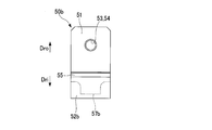
- the second upstream side pressing member 50b has a heat shield ring restricting portion 51, a split ring pressing portion 52b, and a split ring restricting portion 57b as shown in FIGS.
- the heat shield ring restricting portion 51 is a member that enters the pressing member groove 47s in the attached portion 47 of the second upstream heat shield piece 41b.
- segmentation ring pressing part 52b is a member which contacts the upstream side surface of the downstream leg 36 in the 1st division
- the split ring restricting portion 57b is a member that enters the pressing member groove 36s of the first split piece 31a.
- the split ring pressing portion 52 b is located on the radially inner side Dri from the heat shield ring restricting portion 51.
- the split ring restricting portion 57b is located on the radially inner side Dri from the heat shield ring restricting portion 51 and downstream of the split ring pressing portion 52b.
- the heat shield ring restricting portion 51 is formed with a through hole 53 that penetrates in the axial direction Da and communicates with the through hole 48 of the second upstream heat shield piece 41b.
- a female screw (moving guide portion) 54 is formed on the inner peripheral surface of the through hole 53.
- Both the through hole 53 of the second upstream pressing member 50b and the through hole 48 of the second upstream heat shield piece 41b form a hole through which the shaft portion 62 of the second upstream bolt 60b is inserted.
- the heat shield ring restricting portion 51 is formed with a shield plate groove 55 that is recessed from the upstream side toward the downstream side and into which the downstream end of the first shield plate 90a enters.
- the second downstream pressing member 50c includes a heat shield ring restricting portion 51, a stationary blade pressing portion 52, and a stationary blade restricting portion 57c.
- the heat shield ring restricting portion 51 is a member that enters the pressing member groove 47s in the attached portion 47 of the second downstream heat shield piece 41c.
- the stationary blade pressing portion 52 is a member that is located on the radially inner side Dri from the heat shield ring regulating portion 51 and contacts the upstream side surface of the downstream leg 16 of the second stationary blade 11b.
- the stationary blade regulating portion 57c is a member that enters the pressing member groove 16s of the second stationary blade 11b.
- the stationary blade pressing portion 52 is located on the radially inner side Dri from the heat shield ring restricting portion 51. Further, the stationary blade regulating portion 57 c is located on the radially inner side Dri from the heat shield ring regulating portion 51 and on the downstream side from the stationary blade pressing portion 52.
- the heat shield ring restricting portion 51 is formed with a through hole 53 that penetrates in the axial direction Da and communicates with the through hole 48 of the second downstream heat shield piece 41c.
- a female screw (moving guide portion) 54 is formed on the inner peripheral surface of the through hole 53.
- the through hole 53 of the second downstream side pressing member 50c and the through hole 48 of the second downstream side heat shield piece 41c both form a hole through which the shaft portion 62 of the second downstream bolt 60c is inserted.
- the third pressing member 50d is located on the blade ring contact portion 51d that is in contact with the upstream surface of the third attachment portion 21d of the blade ring portion 20 and on the radially inner side Dri from the blade ring contact portion 51d.
- a split ring pressing portion 52d that contacts the downstream leg 36 of the ring 30b.
- the blade ring contact portion 51d is formed with a through hole 53 that penetrates in the axial direction Da and communicates with the through hole 48 of the third heat shield piece 41d.
- a female screw 54 is formed on the inner peripheral surface of the through hole 53.
- the through hole 53 of the third pressing member 50d and the through hole 48 of the third heat shield piece 41d both form a hole through which the shaft portion 62 of the third bolt 60d is inserted.
- the first downstream mounting portion 21a of the blade ring portion 20 is recessed from the radially inner side Dri toward the radially outer side Dro, and the heat shield ring restricting portion 51 of the first downstream pressing member 50a.
- the heat insulation annular groove 22 in which the to-be-attached part 47 of the 1st downstream heat insulation piece 41a enters is formed. That is, on the upstream side and the downstream side in the axial direction across the first downstream heat shield piece 41a, adjacent to the first downstream heat shield piece 41a, the radially outer side Dro of the first downstream heat shield piece 41a.
- An annular upstream side wall 23 and a downstream side wall 25 extending in a convex shape toward the radially inner side Dri are further formed from the outer peripheral surface 41at facing the surface. Further, a groove-shaped heat shield ring groove 22 is formed on the inner peripheral side of the blade ring portion 20 between the upstream side wall 23 and the downstream side wall 25 in the axial direction.
- the through hole 26 of the downstream side wall 25 is a hole into which a first downstream nut (moving guide portion) 65 that can be screwed into a male screw formed on the distal end side of the shaft portion 62 of the first downstream bolt 60a is inserted. Is made.
- the upstream side surface of the downstream side wall 25 of the first downstream attachment portion 21a faces the downstream side surface of the attachment portion 47 in the first downstream heat shield piece 41a, and goes to the downstream side of the first downstream heat shield piece 41a. 25t of the axial direction opposing surface which regulates relative movement of this is comprised.
- the second upstream attachment portion 21b of the blade ring portion 20 is recessed from the radially inner side Dri toward the radially outer side Dro, and the second upstream side pressing member 50b has a heat shield ring restricting portion 51 and a second upstream side heat shield.
- a heat shield ring groove 22 into which the attached portion 47 of the piece 41b enters is formed. That is, on the upstream and downstream sides in the axial direction across the second upstream heat shield piece 41b, adjacent to the second upstream heat shield piece 41b, the radially outer side Dro of the second upstream heat shield piece 41b.
- An annular upstream side wall 23 and a downstream side wall 25 extending in a convex shape toward the radially inner side Dri are further formed from the outer peripheral surface 41bt facing toward the inner side.
- the groove-shaped heat shield ring groove 22 is formed on the inner peripheral side of the blade ring part 20 between the upstream side wall 23 and the downstream side wall 25 in the axial direction.
- the structure around the first downstream side attachment part 21a It is the same.
- the downstream side wall 25 of the heat shield ring groove 22 penetrates in the axial direction Da, and communicates with the through hole 53 of the second upstream pressing member 50b and the through hole 48 of the second upstream heat shield piece 41b. Is formed.
- the through hole 26 of the downstream side wall 25 is inserted with the shaft portion 62 of the second upstream bolt 60b together with the through hole 53 of the second upstream pressing member 50b and the through hole 48 of the second upstream heat shield piece 41b. It has a hole.
- the upstream side surface of the downstream side wall 25 of the second upstream side attachment portion 21b is opposed to the downstream side surface of the attached portion 47 in the second upstream side heat shield piece 41b, and to the downstream side of the second upstream side heat shield piece 41b. 25t of the axial direction opposing surface which regulates relative movement of this is comprised.
- the second downstream mounting portion 21c of the blade ring portion 20 is recessed from the radially inner side Dri toward the radially outer side Dro, and the heat shield ring restricting portion 51 of the second downstream pressing member 50c.
- the heat insulation annular groove 22 in which the to-be-attached part 47 of the 2nd downstream heat insulation piece 41c enters is formed. That is, on the upstream side and the downstream side in the axial direction across the second downstream side heat shield piece 41c, adjacent to the second downstream side heat shield piece 41c, the radially outer side Dro of the second downstream side heat shield piece 41c.
- An annular upstream side wall 23 and a downstream side wall 25 extending in a convex shape toward the radially inner side Dri are further formed from the outer peripheral surface 41ct facing the surface.
- the groove-shaped heat shield ring groove 22 is formed between the upstream side wall 23 and the downstream side wall 25 in the axial direction on the inner peripheral side of the blade ring part. It is the same.
- the downstream side wall 25 of the heat shield ring groove 22 penetrates in the axial direction Da, and communicates with the through hole 53 of the second downstream pressing member 50c and the through hole 48 of the second downstream heat shield piece 41c. Is formed.
- the shaft portion 62 of the second downstream bolt 60c is inserted into the through hole 26 of the downstream side wall 25 together with the through hole 53 of the second downstream pressing member 50c and the through hole 48 of the second downstream heat shield piece 41c. It has a hole.
- the upstream side surface of the downstream side wall 25 of the second downstream side attachment portion 21c faces the downstream side surface of the attached portion 47 in the second downstream side heat shield piece 41c, and goes to the downstream side of the second downstream side heat shield piece 41c. 25t of the axial direction opposing surface which regulates relative movement of this is comprised.
- a through hole 26 that penetrates in the axial direction Da and communicates with the through hole 53 of the third pressing member 50d and the through hole 48 of the third heat shield piece 41d is formed in the third attachment portion 21d of the blade ring portion 20. Yes.
- the through hole 26 of the third mounting portion 21d forms a hole through which the shaft portion 62 of the third bolt 60 is inserted together with the through hole 53 of the third pressing member 50d and the through hole 48 of the third heat shield piece 41d. ing.
- Each pressing member is carried in to the upstream side in the axial direction of each pressing member in the first downstream mounting portion 21a, the second upstream mounting portion 21b, and the second downstream mounting portion 21c of the blade ring portion 20, and the shaft
- a space 80 for attaching each pressing member from the upstream side in the direction is provided.
- the space 80 is formed as an annular space surrounded by the inner peripheral side of the blade ring portion and the outer peripheral surface of each stage stationary blade or split ring.
- each of the packings described above is an elastic metal packing that can be elastically deformed in the axial direction Da.
- the upstream side wall 23 arranged on the upstream side in the axial direction Da of the first downstream heat shield piece 41a has a plurality of through grooves 23s in the circumferential direction Dc through which the first downstream pressing member 50a can be inserted in the axial direction. Is formed.
- the through groove 23s is formed as a pressing member space 80a sandwiched between a pair of circumferentially opposed surfaces 23t facing each other in the circumferential direction Dc of the upstream side wall 23, and the entire surface is open in the direction of the radially inner side Dri.
- the pressing member space 80 a communicates with the space 80.
- the first downstream-side pressing portion is positioned at the upstream side portion in the axial direction Da of the first downstream-side heat shield piece 41a and corresponding to the through groove 23s in the circumferential direction Dc and the axial direction Da.
- a pressing member groove 47s is formed in which the downstream end portion (heat shield ring restricting portion 51) of the member 50a in the axial direction Da enters toward the downstream side in the axial direction Da.
- the mounting structure around the second upstream mounting portion 21b is the same as that of the first downstream mounting portion 21a. That is, as shown in FIGS. 4 and 7, the upstream side wall 23 and the downstream side wall 25 are formed adjacent to the axial direction Da of the second upstream side heat shield piece 41b, and the heat shield ring groove 22 is formed therebetween. Yes. An outer peripheral surface 41bt facing the radially outer side Dro of the second upstream heat shield piece 41b is fitted in a heat shield ring groove 22 formed in the blade ring portion 20.
- the upstream side wall 23 is formed with a plurality of through grooves 23s in the circumferential direction Dc through which the second upstream pressing member 50b can be inserted in the axial direction Da.
- the through groove 23s is formed as a pressing member space 80a sandwiched between a pair of circumferentially opposed surfaces 23t facing each other in the circumferential direction Dc of the upstream side wall 23, and the entire surface is open in the direction of the radially inner side Dri.
- the mounting structure around the second downstream mounting portion 21c is the same as the first downstream mounting portion 21a and the second upstream mounting portion 21b. That is, as shown in FIGS. 5 and 8, the upstream side wall 23 and the downstream side wall 25 are formed adjacent to the axial direction Da of the second downstream side heat shield piece 41c, and the radial direction of the second downstream side heat shield piece 41c. An outer peripheral surface 41ct facing the outer side Dro is fitted in a heat shield ring groove 22 formed in the blade ring portion 20.
- the structure of the through groove 23s through which the second downstream pressing member 50c provided in the upstream side wall 23 can be inserted in the axial direction Da and the structure of the pressing member groove 47s provided in the second downstream heat shielding piece 41c are also first. This is the same as the structure around the one downstream mounting portion 21a.
- a pressing member is arranged on the upstream side in the axial direction Da, and the pressing member and the blade ring are arranged.
- a heat shield ring is sandwiched between the portion (downstream side wall 25) and fixed to the blade ring portion from the axial direction Da by bolt fastening.
- the heat shield ring needs to be held at a proper position so that the heat shield ring does not move in the axial direction Da due to the restoring force of the packing because it is attached in a held state. In this way, the position of the heat shield ring is always fixed during operation and when it is stopped, and stable operation of the gas turbine can be maintained.
- the predetermined heat shield rings are the first downstream heat shield ring 40a, the second upstream heat shield ring 40b, and the second downstream heat shield ring 40c.
- the upstream member with respect to the first downstream heat shield ring 40a is the first stationary blade stage 10a, and the downstream member is the first split ring 30a.
- the upstream member for the second upstream heat shield ring 40b is the first split ring 30a, and the downstream member is the second stationary blade stage 10b.
- the upstream side member with respect to the second downstream side heat shield ring 40c is the second stationary blade stage 10b, and the downstream side member is the second split ring 30b.
- a first downstream nut 65 (moving guide portion) as a part of the blade ring portion 20 is inserted into the through hole 26 of the first downstream attachment portion 21 a of the blade ring portion 20. Is incorporated (step 1).
- the second upstream heat shield piece 41b constituting the second upstream heat shield ring 40b which is a predetermined heat shield ring, is surrounded by the heat shield ring groove 22 in the second upstream attachment portion 21b of the blade ring portion 20. Insert from direction Dc.
- the second upstream pressing member 50b is attached from the axial direction Da through the space 80 on the upstream side of the second upstream heat shield ring 40b and the through groove 23s.
- the second upstream heat shield piece 41b and the second upstream pressing member 50b are fixed from the axial direction Da with the second upstream bolt 60b.
- the heat shield ring restricting portion 51 of the second upstream pressing member 50b is attached to the pressing member groove 47s of the second upstream heat blocking piece 41b.
- the downstream protrusion 37 of the first divided piece 31a is connected to the first upstream heat shield piece 41b. Insert into the split ring mounting groove 45b. Further, the first split ring downstream packing 70b is inserted into the packing groove 43 of the second upstream heat shield piece 41b from the circumferential direction Dc and fixed simultaneously with the second upstream bolt 60b. In the process of tightening with the second upstream bolt 60b, the second upstream pressing member 50b presses the second upstream heat shielding piece 41b on the downstream side in the axial direction, and the packing 70b is compressed in the axial direction Da to seal the packing 70b. Sex is maintained.
- the first downstream heat shield piece 41a with the first divided ring upstream packing 70a attached is inserted from the circumferential direction Dc into the heat shield ring groove 22 in the first downstream attachment portion 21a of the blade ring part 20.
- the first downstream pressing member 50a is attached from the axial direction Da via the space 80 on the upstream side of the first downstream heat shield ring 40a and the through groove 23s. Further, the first downstream heat shield piece 41a and the first downstream pressing member 50a are fixed from the axial direction Da by the first downstream bolt 60a. At this time, the heat shield ring restricting portion 51 of the first downstream pressing member 50a is put into the pressing member groove 47s of the first downstream heat blocking piece 41a.
- the first downstream pressing member 50a presses the first downstream heat shielding piece 41a axially downstream, and the packing 70a Compressed in the direction Da, the sealing performance of the packing 70a is maintained.
- the second downstream heat shield piece 41 c is inserted from the circumferential direction Dc into the heat shield ring groove 22 in the second downstream attachment portion 21 c of the blade ring portion 20.
- the second downstream pressing member 50c is attached from the axial direction Da via the upstream space 80 and the through groove 23s of the second downstream thermal shield ring 40c, and is fixed from the axial direction Da by the second downstream bolt 60c.
- the heat shield ring restricting portion 51 of the second downstream pressing member 50c is put into the pressing member groove 47s of the second downstream heat blocking piece 41c.
- the second stationary blade 11b to which the second stationary blade upstream packing 71b and the second stationary blade downstream packing 71c are attached is connected to the second upstream heat shielding piece 41b and the second stationary blade 11b. It is assembled from the circumferential direction Dc between the downstream heat shield piece 41c and fixed by the second downstream bolt 60c.
- the second downstream pressing member 50c presses the second downstream heat shielding piece 41c axially downstream, and the packing 71c is compressed in the axial direction Da to seal the packing 70c. Sex is maintained.
- the third pressing member 50d is assembled on the upstream side of the third attachment portion 21d of the blade ring portion 20.
- the upstream protrusion 35 of the second split piece 31b is inserted into the second split ring mounting groove 45c of the second downstream heat shield piece 41c, and the second split ring upstream packing 70c is inserted into the second downstream heat shield ring. It is pushed into the packing groove 43 of 40c from the axial direction Da. Then, the 3rd heat insulation piece 41d which attached the 2nd division
- the third heat shield piece 41d and the second divided piece 31b are pushed upstream in the axial direction, the packings 70c and 70d are compressed, and the sealing properties of the packings 70c and 70d are compressed. Is maintained.
- the blade ring portion 20 in which the first blade ring portion 20a to which the first stator blade 11a is attached and the second blade ring portion 20b to which the second stator blade 11b is attached is integrally formed.
- high-accuracy clearance control is possible for the combined blade ring as a whole, and the performance of the turbine is further improved.
- the packing applied to the first split ring 30a and the like is compressed in the axial direction Da while The one-segment ring 30 a and the like can be fixed to the blade ring part 20.
- the pressing member 50 is disposed on the upstream side of the predetermined heat shield ring 40 for each predetermined heat shield ring 40, and these press members 50 are moved downstream by the operation of the bolt 60. This is because it is pushed to the side.
- the gas turbine of the present embodiment is different from the first embodiment in the configuration of the blade ring portion 20 (union blade ring 20x) and various attachment parts to the blade ring portion 20 in the first embodiment.
- the blade ring portion 20 (union blade ring 20y) of the present embodiment and various attachment parts for the blade ring portion 20 (union blade ring 20y) will be described.
- the blade ring portion 20 of the present embodiment includes a plurality of first stator blades 11a and second stator blade stages 10b constituting the first stator blade stage 10a, as in the first embodiment.
- the second split ring 30b is attached.
- the blade ring portion 20 includes a fixed block 49, a first downstream side heat shield ring 40f, a second upstream side heat shield ring 40g, and a second downstream side heat shield ring 40h, as in the first embodiment.
- the third heat shield ring 40i is attached.
- the fixed block 49 is a member for attaching the upstream side portion of the outer shroud 13 of the first stationary blade 11 a to the blade ring portion 20.
- the first downstream side heat shield ring 40f is a member for attaching the downstream side portion of the outer shroud 13 of the first stationary blade 11a and the upstream side portion of the first split ring 30a to the blade ring portion 20.
- the second upstream side heat shield ring 40g attaches the first downstream side heat shield ring 40f, the downstream side portion of the first split ring 30a, and the upstream side portion of the outer shroud 13 of the second stationary blade 11b to the blade ring portion 20. It is a member for.
- the second downstream side heat shield ring 40h is a member for attaching the downstream side portion of the outer shroud 13 of the second stationary blade 11b and the upstream side portion of the second split ring 30b to the blade ring portion 20.
- the third heat shield ring 40 i is a member for attaching the downstream side portion of the second split ring 30 b to the blade ring portion 20.
- a first upstream attachment portion 21j to which a fixing block 49 for the first stationary blade 11a is attached, and a first downstream portion A side heat shield ring 40f and a first downstream attachment portion 21f to which the first downstream pressing member 50f is attached are formed on the inner peripheral side of the second blade ring portion 20g of the blade ring portion 20, a second upstream attachment portion 21g to which the second upstream heat shield ring 40g and the second upstream pressing member 50g are attached, A second downstream attachment portion 21h to which the downstream heat shield ring 40h is attached and a third attachment portion 21i to which the third heat shield ring 40i is attached are formed.
- each mounting portion is, from the upstream side toward the downstream side, the first upstream side mounting portion 21j, the first downstream side mounting portion 21f, the second upstream side mounting portion 21g, and the second downstream side mounting.
- the part 21h and the third attachment part 21i are arranged in this order.
- the first downstream attachment portion 21f and the second upstream attachment portion 21g are shielded from the inner peripheral side of the blade ring portion 20 toward the radially outer side Dro.
- a thermal ring groove 22 is formed.
- Each heat shield ring is arranged such that the outer peripheral surface facing the radially outer side Dro contacts the heat shield ring groove 22 from the radially inner side Dri.
- a convex downstream side wall 25 extending from the outer peripheral surface of the heat shield ring toward the radially inner side from the blade ring portion 20 is formed. .
- annular space 80 is formed between the inner peripheral side of the blade ring portion 20 and the outer peripheral surface of the stationary blade stage or the split ring in the radial direction.
- An annular pressing member space 80 a is formed between the upstream side surface 25 f of the heat shield ring groove 22 and the attached portion 47 of the heat shield ring disposed on the downstream side in the axial direction Da, and communicates with the space 80. ing.
- the pressing member is inserted into the pressing member space 80a via the space 80 from the radially inner side Dri, and is fixed to the blade ring portion 20 from the radially inner side Dri.
- the pressing member, the heat shield ring, and the downstream side wall are arranged in this order from the upstream side to the downstream side in the axial direction Da, and the heat shielding ring is interposed from the axial direction with the heat shield ring interposed therebetween.
- a structure sandwiching the ring is formed.
- the first split ring 30a and the second split ring 30b are configured to have a plurality of split pieces 31a and 31b as in the first embodiment.
- each of the divided pieces 31 a and 31 b also has a divided piece main body 32 that extends in the circumferential direction Dc, and an upstream leg that extends from the upstream side of the divided piece main body 32 to the radially outer side Dro. 34 and a downstream leg 36 extending from the downstream side portion of the divided piece body 32 to the radially outer side Dro.
- An upstream protrusion 35 protruding toward the upstream side is formed at the radially outer end of the upstream leg 34.
- a downstream protrusion 37 protruding toward the downstream side is formed at the radially outer end of the downstream leg 36.
- the downstream protrusions 37 in the plurality of first divided pieces 31a constituting the first divided ring 30a and the downstream protrusions 37 in the plurality of second divided pieces 31b constituting the second divided ring 30b are respectively from the upstream side.
- a pin groove 37u penetrating downstream is formed.
- a restriction member groove 15u penetrating from the downstream side to the upstream side is formed in the upstream protrusion 15 of the plurality of second stator blades 11b constituting the second stator blade stage 10b.
- each of the heat shield rings 40f, 40g, 40h, 40i is also configured to have a plurality of heat shield pieces 41f, 41g, 41h, 41i, as in the first embodiment.
- Each of the heat shield pieces 41f, 41g, 41h, 41i is located on the inner ring attachment portion 42 to which the stationary blade 11 and / or the split piece 31 are attached, and on the radially outer side Dro with respect to the inner ring attachment portion 42. And an attached portion 47 attached to the portion 20.
- the inner ring mounting portion 42 of the plurality of first downstream heat shield pieces 41f constituting the first downstream heat shield ring 40f is arranged from the upstream side to the downstream side.
- a first stator blade mounting groove 42f into which the downstream protrusion 17 of the first stator blade 11a enters is formed.
- the inner ring mounting portion 42 of the first downstream side heat shield piece 41f is recessed from the downstream side to the upstream side, and a first divided ring mounting groove 45f into which the upstream protrusion 35 of the first divided piece 31a enters.
- a packing groove 43 that is recessed from the downstream side to the upstream side and into which the first split ring upstream packing 70a enters is formed.
- the attached portion 47 of the first downstream heat shield piece 41f is recessed from the upstream side toward the downstream side, extends in the radial direction Dr, and a part of the first downstream pressing member 50f enters the diameter.
- a guide groove 48f that can slide in the direction Dr is formed.
- the guide groove 48f is formed with a pair of circumferentially opposed surfaces 48t (FIG. 15) that are opposed to each other in the circumferential direction Dc.
- the attached portion 47 is formed with a top projection 49f that protrudes toward the downstream side and restricts the position of the first downstream heat shield piece 41f in the radial direction Dr with respect to the blade ring portion 20.
- the radial inner ring attachment portion 42 of the plurality of second upstream heat shield pieces 41 g constituting the second upstream heat shield ring 40 g is arranged from the upstream side.
- a first divided ring mounting groove 45g is formed which is recessed downstream and into which the downstream protrusion 37 of the first divided piece 31a enters.
- a packing groove 43 is formed which is recessed from the upstream side to the downstream side and into which the first split ring downstream side packing 70b enters.
- a packing groove 44 that is recessed from the downstream side to the upstream side and into which the second stationary blade upstream side packing 71b enters is formed in the inner ring mounting portion 42 of the second upstream side heat shield piece 41g.
- a pin hole 45u (FIG. 14) is formed in a part of the circumferential direction Dc of the first split ring mounting groove 45g.
- the pin hole 45u is recessed from the groove bottom of the first split ring mounting groove 45g to the downstream side.
- the attached portion 47 of the second upstream side heat shield piece 41g is recessed from the upstream side toward the downstream side and extends in the radial direction Dr, so that the second upstream side
- a guide groove portion 48g is formed in which a part of the side pressing member 50g enters and is slidable in the radial direction Dr.
- the guide groove 48g is formed with a pair of circumferentially opposed surfaces 48t (FIG.
- the attached portion 47 is formed with a top projection 49g that protrudes toward the downstream side and restricts the position of the second upstream heat shield piece 41g in the radial direction Dr with respect to the blade ring portion 20.
- the inner ring mounting portion 42 of the plurality of second downstream heat shield pieces 41h constituting the second downstream heat shield ring 40h is recessed from the upstream side to the downstream side as shown in FIG. A second stator blade mounting groove 46h into which the downstream protrusion 17 of the blade 11b enters, and a packing groove 44 recessed from the upstream side to the downstream side into which the second stator blade downstream packing 71c enters. Further, the inner ring mounting portion 42 of the second downstream side heat shield piece 41h is recessed from the downstream side to the upstream side, and a second divided ring mounting groove 45h into which the upstream protrusion 35 of the second divided piece 31b enters.
- a packing groove 43 that is recessed from the downstream side to the upstream side and into which the upstream packing 70c of the second split ring enters is formed.
- a protrusion 49h is formed projecting from the upstream side toward the downstream side, and on the downstream side of the attached portion 47, A protrusion 49h that protrudes from the downstream side toward the upstream side is formed.
- Each of these protrusions 49h regulates the position of the second downstream heat shield piece 41h in the radial direction Dr with respect to the blade ring portion 20.
- a pin groove 49u that is provided on the downstream side of the attached portion 47 and protrudes from the downstream side toward the upstream side is formed with a pin groove 49u that is recessed from the downstream side toward the upstream side.
- the inner ring mounting portion 42 of the plurality of third heat shield pieces 41i constituting the third heat shield ring 40i is recessed from the upstream side to the downstream side, and the second protrusion 37 of the second divided piece 31b enters the second ring fitting portion 42b.
- the split ring mounting groove 45i and a packing groove 43 that is recessed from the upstream side to the downstream side and into which the second split ring downstream side packing 70d enters are formed.
- the second split ring mounting groove 45i is formed with a pin hole 45u recessed in the downstream side from the groove bottom of the second split ring mounting groove 45i in a part of the circumferential direction thereof.
- a through-hole 48 through which the shaft 47 of the third bolt 60 i and the sleeve 67 attached to the shaft 62 are inserted is inserted into the attached portion 47 of the third heat shield piece 41 i in the axial direction Da. Is formed.
- the first downstream pressing member 50f has a guide protrusion 52f that is recessed from the downstream side to the upstream side and enters the guide groove portion 48f of the first downstream heat shield piece 41f, and a diameter.
- a through hole 53 that penetrates in the direction Dr and into which the shaft portion 62 of the first downstream bolt 60f can be inserted is formed.
- the second upstream pressing member 50g is recessed from the downstream side to the upstream side like the first downstream pressing member 50f, and the guide groove portion of the second upstream heat shielding piece 41g.
- a guide protrusion 52g entering 48g and a through hole 53 penetrating in the radial direction Dr and allowing the shaft portion 62 of the second upstream bolt 60g to be inserted therethrough are formed.
- the first downstream attachment portion 21f of the blade ring portion 20 is recessed from the radial inner side Dri toward the radial outer side Dro, and the first downstream pressing member 50f and the first downstream side A heat shield ring groove 22 into which the attached portion 47 of the side heat shield piece 41f enters is formed.
- the first downstream mounting portion 21f has a female screw hole 23f extending from the groove bottom of the heat shield ring groove 22 toward the radially outer side Dro and capable of being screwed with the male screw 63 of the first downstream bolt 60f. Is formed.
- first downstream attachment portion 21f is formed with a side wall groove 24f that is recessed from the downstream side wall of the heat shield ring groove 22 toward the downstream side and into which the top projection 49f of the first downstream heat shield piece 41f enters.
- the upstream side surface 25f of the heat shield ring groove 22 may be formed with an inclined surface that gradually goes downstream as it goes toward the radially outer side Dro as a movement guide portion of the first downstream pressing member 50f. .
- the downstream side surface 56f of the first downstream side pressing member 50f and the upstream side surface 46f of the attached portion 47 of the first downstream side heat shield piece 41f are in contact with each other.
- the first downstream-side pressing member 50f is a bolt 60f that is screwed into the female screw hole 23f while pressing the attached portion 47 of the first downstream-side heat shield piece 41f downstream through this contact surface. It is fixed to the one downstream side attachment portion 21f. Thereby, it arrange
- a structure is formed that is sandwiched between the first downstream pressing member 50f and the downstream side wall 25 from the axial direction Da.
- the first downstream pressing member 50f presses the first downstream heat shield piece 41f on the downstream side in the axial direction Da, and the mounted portion 47 of the first downstream heat shield piece 41f is on the downstream side in the axial direction Da.
- the packing 70a disposed in the packing groove 43 is compressed in the axial direction Da, and the sealing performance of the packing 70a is maintained.
- the attached portion 47 and the top projection 49f of the first downstream side heat shield piece 41f can be attached to and detached from the heat shield ring groove 22 and the side wall groove 24f from the radial direction Dr and the axial direction Da.
- the gap D in the axial direction Da between the upstream side surface 46f of the attached portion 47 and the upstream side surface 25f of the heat shield ring groove 22 is formed to be larger than the axial projection length (L3) of the top projection 49f. It is necessary to be.
- the apex thickness (L2) in the radial direction outside the attached portion 47 and in the axial direction projects at least from the maximum groove width (L1) in the axial direction Da of the heat shield ring groove 22 in the axial direction.
- the groove width needs to be smaller than the groove width obtained by subtracting the length (L3). If such a shape is selected, the first downstream heat shield piece 41f (attached portion 47) is inserted into the heat shield ring groove 22 from the radially inner side Dri via the space 80 and the pressing member space 80a, and the shaft The top protrusion 49f can be inserted into the side wall groove 24f from the axial direction Da, and the first downstream heat shield piece 41f can be attached and detached from the axial direction Da. Conversely, when disassembling, the first downstream heat shield piece 41f can be removed from the axial direction Da. It is desirable that the width of the pressing member space 80a in the axial direction Da is at least larger than the gap D.
- the second upstream attachment portion 21g of the blade ring portion 20 is recessed from the radial inner side Dri toward the radial outer side Dro, and the second upstream pressing member 50g and the second upstream side A heat shield ring groove 22 into which the attached portion 47 of the side heat shield piece 41g enters is formed.
- the second upstream attachment portion 21g has a female screw hole extending from the groove bottom of the heat shield ring groove 22 toward the radially outer side Dro and capable of being screwed with the male screw 63 of the second upstream bolt 60g. 23 g is formed.
- the second upstream attachment portion 21g is formed with a side wall groove 24g that is recessed from the downstream side wall of the heat shield ring groove 22 toward the downstream side and into which the top protrusion 49g of the second upstream heat shield piece 41g enters. ing.
- the upstream side surface 25g of the heat shield ring groove 22 may be formed with an inclined surface gradually moving toward the downstream side toward the radially outer side Dro as a moving guide portion of the second upstream pressing member 50g. .
- the heat shield ring groove 22 of the second upstream heat shield ring 40g is formed by grooves 22o and 22i cut in two stages in the radial direction Dr.
- the outer heat shield ring groove 22o is disposed outside the radial direction Dr, and the attached portion 47 of the second upstream heat shield piece 41g is in contact with the bottom surface of the outer heat shield ring groove 22o on the radially outer surface.
- an inner heat shield ring groove 22i is formed adjacent to the upstream side of the outer heat shield ring groove 22o.
- the aforementioned through hole 53 is formed in the radial direction on the radially inner peripheral surface of the inner heat shield ring groove 22i.
- the upstream side surface 25gi of the inner heat shield ring groove 22i forms the aforementioned upstream side surface 25g of the heat shield ring groove 22 together with the upstream side surface 25go of the outer heat shield ring groove 22o.
- the heat shield ring groove 22 of the second upstream heat shield ring 40g is not a groove formed in two stages, but is similar to the heat shield ring groove 22 of the first downstream heat shield ring 40f in the axial direction Da. You may form by one groove
- the downstream side surface 56g of the second upstream side pressing member 50g and the upstream side surface 46g of the second upstream side heat shield piece 41g are mutually connected.
- the second upstream pressing member 50g is a bolt 60g that is screwed into the female screw hole 23g while pushing the attached portion 47 of the second upstream heat shielding piece 41g downstream through this contact surface. It is fixed to the upstream attachment portion 21g.
- the first downstream attachment portion 21f is arranged in the order of the first downstream pressing member 50f, the first downstream heat shield piece 41f, and the downstream side wall 25 from the upstream side in the axial direction Da toward the downstream side.
- the first downstream pressing member 50f is arranged on the upstream side and the downstream side wall 25 is arranged on the downstream side to sandwich the first downstream heat shielding piece 41f from the axial direction Da.
- the second upstream attachment portion 21g is arranged in the order of the second upstream pressing member 50g, the second upstream heat shielding piece 41g, and the downstream side wall 25, and the second upstream pressing member 50g and the downstream are disposed upstream.
- the downstream side wall 25 is disposed on the side, and the second upstream heat shielding piece 41g is sandwiched from the axial direction Da.
- the first downstream pressing member 50f presses the first downstream heat shield piece 41f on the downstream side in the axial direction Da, and the mounted portion 47 of the second upstream heat shield piece 41g is on the downstream side in the axial direction Da.
- the packing 71b disposed in the packing groove 44 is compressed in the axial direction Da, and the sealing performance of the packing 71b is maintained.
- the attached portion 47 and the top projection 49g of the second upstream heat shield piece 41g can be attached to and detached from the outer heat shield ring groove 22o and the side wall groove 24g from the radial direction Dr and the axial direction Da.
- the gap D between the upstream side surface 46gi of the attached portion 47 and the upstream side surface 25go on the radially outer side of the outer heat shield ring groove 22o is larger than the protruding length (L3) in the axial direction of the top projection 49g. It must be formed.
- the top thickness (L2) in the radial direction outside the attached portion 47 and in the axial direction Da is at least the axis of the top projection 49g than the maximum groove width (L1) in the axial direction Da of the outer heat shield ring groove 22o.
- the groove width needs to be smaller than the groove width obtained by subtracting the direction protrusion length (L3). If such a shape is selected, the attached portion 47 can be inserted into the outer heat shield ring groove 22o from the inside in the radial direction, and the top protrusion 49g can be inserted into the side wall groove 24g from the axial direction Da. On the contrary, when removing, the attached portion 47 of the second upstream heat shield piece 41g can be removed from the axial direction Da.
- the heat shield ring groove 22 is not a groove cut in two stages in the radial direction Dr, but is formed by a single groove whose width in the axial direction Da is increased, like the first downstream heat shield ring 40f. If so, the above description can replace the outer heat shield ring groove 22o with the heat shield ring groove 22.
- the second upstream attachment portion 21g is located at the same position as the regulating member groove (recessed portion) 15u of the second stationary blade 11b in the circumferential direction Dc and the axial direction Da.
- a regulating member groove (concave portion) 21u penetrating from the downstream side to the upstream side is formed.
- a circumferential direction regulating member 95 is inserted into the regulating member groove 15u of the second stationary blade 11b and the regulating member groove 21u of the second upstream attachment portion 21g.
- a restricting member receiving plate 97 that closes the downstream opening of the restricting member groove 21u is fixed to the second upstream attachment portion 21g by a bolt 96.
- the second downstream mounting portion 21h of the blade ring portion 20 is recessed from the radial inner side Dri toward the radial outer side Dro, and a mounted portion 47 of the second downstream heat shielding piece 41h is provided.
- a heat shield ring groove 22 is formed.
- the third mounting portion 21i of the blade ring portion 20 is formed with a heat shield ring groove 22 that is recessed toward the radially outer side Dro and the upstream side and into which the mounted portion 47 of the third heat shield piece 41i enters.
- a female screw hole 23 i is formed that is recessed from here to the upstream side and into which the male screw 63 of the third bolt 60 d can be screwed.
- a pin hole 24 u penetrating to the heat shield ring groove 22 of the second downstream attachment portion 21 h is formed on the upstream side wall of the heat shield ring groove 22.
- the predetermined heat shield rings are the first downstream heat shield ring 40f and the second upstream heat shield ring 40g.
- the upstream side member with respect to the first downstream side heat shield ring 40f is the first stationary blade stage 10a, and the downstream side member is the first split ring 30a.
- the upstream member for the second upstream heat shield ring 40g is the first split ring 30a, and the downstream member is the second stationary blade stage 10b.
- the attached portion 47 of the second downstream heat shield piece 41 h is inserted from the circumferential direction Dc into the heat shield ring groove 22 in the second downstream attachment portion 21 h of the blade ring portion 20.
- a pin (circumferential regulating member) 60h is downstream in a pin hole 24u penetrating from the upstream side wall 23 of the heat shield ring groove 22 of the third attachment portion 21i to the heat shield ring groove 22 of the second downstream side attachment portion 21h.
- the upstream end of the pin 60h is inserted into the pin groove 49u of the second downstream heat shield piece.
- the upstream protrusion 35 of the second split piece 31b is inserted into the second split ring mounting groove 45h of the second downstream heat shield piece 41h from the axial direction Da, and the second split ring upstream packing 70c is connected to the second downstream side. It inserts into the packing groove
- the third heat shield piece 41 i to which the second split ring downstream packing 70 d is attached is inserted into the heat shield ring groove 22 in the third attachment portion 21 i of the blade ring portion 20.
- a pin (circumferential regulating member) 65i is inserted into the pin groove (concave portion) 37u of the second divided piece 31b and the pin hole (concave portion) 45u of the third heat shield piece 41i from the upstream side thereof, and the third shield.
- the movement in the circumferential direction Dc of the second divided piece 31b relative to the heat piece 41i is constrained.
- the third bolt 60i to which the sleeve 67 is attached is inserted into the through hole 48 of the third heat shield piece 41i and screwed into the female screw hole 23i of the third mounting portion 21i. 41i is fixed to the 3rd attachment part 21i.
- downstream protrusion 17 of the second stator blade 11b is inserted into the second stator blade mounting groove 46h of the second downstream heat shield piece 41h, and the second stator blade downstream packing 71c is inserted into the second downstream heat shield piece. It is inserted into the packing groove 44 of 41h from the axial direction Da.
- the restricting member receiving plate 97 is fixed to the second upstream attachment portion 21 g with bolts 98.
- the circumferential restriction member 95 is inserted into the restriction member groove (recess) 15u of the second stationary blade 11b and the restriction member groove (recess) 21u of the second upstream attachment portion 21g from the upstream side.
- the bolt 96 is screwed into the female screw 97 a of the regulating member receiving plate 97 through the through hole 95 a of the circumferential regulating member 95 to fix the circumferential regulating member 95.
- the second upstream pressing member 50g is inserted into the heat shield ring groove 22 of the second upstream attachment portion 21g from the radially inner side, and the second upstream heat shield piece 41g is brought into contact with the downstream side in the axial direction.
- the second upstream pressing member 50g is fixed to the second upstream attachment portion 21g with the second upstream bolt 60g.
- the guide protrusion 52g of the second upstream pressing member 50g is inserted into the guide groove 48g of the second upstream heat shield piece 41g.
- the shaft portion 62 of the second upstream bolt 60g is inserted into the through hole 53 of the second upstream pressing member 50g and screwed into the female screw hole 23g formed in the groove bottom of the heat shield ring groove 22,
- the second upstream pressing member 50g is fixed from the radially outer side Dro.
- the second stationary blade upstream side packing 71b is compressed in the axial direction Da, and the second upstream side heat shield piece 41g, the second stationary blade 11b, Is sealed. Further, the second stator blade 11b is pushed downstream by the second upstream heat shield piece 41g, the second stator blade downstream packing 71c (FIG. 18) is compressed in the axial direction Da, and the second stator blade 11b and the second stator blade 11b The space between the two downstream side heat shield pieces 41h is sealed.
- downstream protrusion 37 of the first split piece 31a is inserted into the first split ring mounting groove 45g of the second upstream heat shield piece 41g, and the first split ring downstream packing 70b is inserted into the second upstream heat shield piece. Insert into the 41 g packing groove 43.
- a pin (circumferential regulating member) 65g is inserted into the pin groove (concave portion) 37u of the first divided piece 31a and the pin hole (concave portion) 45u of the second upstream heat shield piece 41g from the upstream side, and the first The movement of the first divided piece 31a in the circumferential direction Dc with respect to the two upstream heat shield pieces 41g is restrained.
- the first downstream pressing member 50f is inserted into the heat shield ring groove 22 of the first downstream mounting portion 21f, and the first downstream pressing member 50f is mounted on the first downstream side with the first downstream bolt 60f. It fixes to the part 21f.
- the guide protrusion 52f of the first downstream pressing member 50f is inserted into the guide groove 48f of the first downstream heat shielding piece 41f, and the downstream side surface 56f of the first downstream pressing member 50f is inserted into the first downstream heat shielding.
- the upstream side surface 46f of the attached portion 47 of the piece 41f is brought into contact in the axial direction Da, and the first downstream side heat shielding piece 41f is pushed axially downstream by the first downstream side pressing member 50f.
- the first divided ring upstream packing 70a is compressed in the axial direction Da, and the first downstream heat shield 41f, the first divided piece 31a, Is sealed. Further, the first divided piece 31a is pushed downstream by the first downstream side heat shield piece 41f, the first divided ring downstream packing 70b is compressed in the axial direction Da, and the first divided piece 31a and the second upstream side shielding piece are compressed. The space between the heat pieces 41g is sealed. Further, the positioning of the first divided piece 31a in the radial direction Dr and the axial direction Da is completed by the screwing of the first downstream bolt 60f.
- downstream protrusion 17 of the first stator blade 11a is inserted into the first stator blade mounting groove 42f of the first downstream heat shield ring 40f, and the fixed block 49 is fixed to the first upstream mounting portion 21j of the blade ring portion 20. (FIG. 11) is fixed.
- the first blade ring portion 20f to which the first stator blade 11a is attached and the second blade ring portion 20g to which the second stator blade 11b is attached are integrally formed as in the first embodiment. Since the blade ring portion 20 (combined blade ring 20y) is formed, high-accuracy clearance control of the combined blade ring as a whole is possible, and the performance of the turbine is further improved.
- the packing for the first split ring 30a and the second stationary blade 11b disposed near the center of the axial direction Da of the blade ring portion 20 is compressed in the axial direction Da during the assembly process.
- the first split ring 30 a and the second stationary blade 11 b can be fixed to the blade ring portion 20.
- the parts can be incorporated into the blade ring part 20 more easily than in the first embodiment.
- each of the blade ring portions 20 of each of the embodiments described above is provided with two stages of stationary blades 11 attached thereto, but a larger number of stages of stationary blades 11 may be attached.
- the blade ring portion 20 here attaches a plurality of stationary blade stages 10 including the most upstream first stationary blade stage 10a, but a plurality of stationary blades downstream from the first stationary blade stage 10a. A step may be attached.
- the present invention relates to a gas turbine including a rotor and a casing covering the rotor, and more particularly, to a structure of a gas turbine casing.
- ADVANTAGE OF THE INVENTION According to this invention, the assembly property of the casing which integrated the some blade ring part is securable.
Landscapes
- Engineering & Computer Science (AREA)
- Mechanical Engineering (AREA)
- General Engineering & Computer Science (AREA)
- Chemical & Material Sciences (AREA)
- Combustion & Propulsion (AREA)
- Turbine Rotor Nozzle Sealing (AREA)
Description
本願は、2012年8月30日に日本に出願された特願2012-190008号について優先権を主張し、その内容をここに援用する。
回転軸線を中心として回転するロータ本体、及び該回転軸線が延びている軸方向に並んで該ロータ本体に固定されている複数の動翼段を有するロータと、複数の動翼段のそれぞれの上流側に配置されている複数の静翼段と、該ロータを覆うと共に複数の該静翼段が内周側に取り付けられているケーシングと、を備え、
前記ケーシングは、前記回転軸線を中心として環状を成し、一つの前記動翼段及び一つの前記静翼段を覆う複数の翼環部と、前記回転軸線を中心として環状を成し、前記翼環部の内周側で且つ前記動翼段の外周側であって、複数の前記静翼段の相互間に配置される複数の分割環と、前記静翼段の上流側又は下流側に配置される前記分割環を取り付けるための複数の遮熱環と、を備えているガスタービンにおいて、
前記軸方向で互いに隣り合っている二以上の前記翼環部は一体形成された合体翼環を成し、
複数の前記遮熱環のうちで所定遮熱環には、前記分割環と前記静翼段とのうちで該所定遮熱環の上流側に配置された上流側部材が取り付けられると共に、該分割環と該静翼段とのうちで該所定遮熱環の下流側に存在する下流側部材が取り付けられ、
前記ケーシングは、さらに、
前記所定遮熱環の上流側に配置されて、前記翼環部に取り付けられ、該所定遮熱環と前記上流側部材とのうちの少なくとも一方の被押付部材を下流側に押す押付部材と、
を備えている。
前記押付部材は、径方向内側から前記遮熱環溝に入れられて、前記翼環部に取り付けられていてもよい。
前記押付部材と前記翼環部とのうちの一方の前記貫通孔の内周面には、前記ボルトの前記雄ネジが螺合する雌ネジが形成されていてもよい。
前記所定遮熱環は、複数の前記分割環のうち、前記第一静翼段と前記第二静翼段との間に配置される第一分割環の下流側部を前記第二翼環部に取り付けると共に、前記第二静翼の外側シュラウドにおける上流側部を前記第二翼環部に取り付ける第二上流側遮熱環を含み、前記上流側部材は前記第一分割環であり、前記下流側部材は前記第二静翼段であってもよい。
まず、本発明に係る第一実施形態としてのガスタービンについて、図1~図10を参照して説明する。
第一下流側遮熱片41aの軸方向Daの上流側に配置された上流側壁23には、第一下流側押付部材50aが軸方向に挿通可能な貫通溝23sが、周方向Dcに複数個形成されている。貫通溝23sは、上流側壁23の周方向Dcで互いに対向する一対の周方向対向面23tに挟まれた押付部材空間80aとして形成され、径方向内側Driの方向は全面が開口している。押付部材空間80aは、空間80に連通している。
次に、本発明に係る第二実施形態としてのガスタービンについて、図11~図18を参照して説明する。
Claims (17)
- 回転軸線を中心として回転するロータ本体、及び該回転軸線が延びている軸方向に並んで該ロータ本体に固定されている複数の動翼段を有するロータと、複数の動翼段のそれぞれの上流側に配置されている複数の静翼段と、該ロータを覆うと共に複数の該静翼段が内周側に取り付けられているケーシングと、を備え、
前記ケーシングは、前記回転軸線を中心として環状を成し、一つの前記動翼段及び一つの前記静翼段を覆う複数の翼環部と、前記回転軸線を中心として環状を成し、前記翼環部の内周側で且つ前記動翼段の外周側であって、複数の前記静翼段の相互間に配置される複数の分割環と、前記静翼段の上流側又は下流側に配置される前記分割環を取り付けるための複数の遮熱環と、を備えているガスタービンにおいて、
前記軸方向で互いに隣り合っている二以上の前記翼環部は一体形成された合体翼環を成し、
複数の前記遮熱環のうちで所定遮熱環には、前記分割環と前記静翼段とのうちで該所定遮熱環の上流側に配置された上流側部材が取り付けられると共に、該分割環と該静翼段とのうちで該所定遮熱環の下流側に存在する下流側部材が取り付けられ、
前記ケーシングは、さらに、
前記所定遮熱環の上流側に配置されて、前記翼環部に取り付けられ、該所定遮熱環と前記上流側部材とのうちの少なくとも一方の被押付部材を下流側に押す押付部材を備えているガスタービン。 - 請求項1に記載のガスタービンにおいて、
前記ケーシングは、軸方向の上流側から下流側に向かって、前記押付部材、前記所定遮熱環および前記翼環部のうち前記所定遮熱環の外周面より更に径方向の内側に延びる下流側壁の順に配置された構造を備え、前記所定遮熱環を軸方向から前記押付部材および前記下流側壁で挟む構造を備えているガスタービン。 - 請求項2に記載のガスタービンにおいて、
前記翼環部は、前記所定遮熱環の上流側に隣接して、前記所定遮熱環の外周面より更に径方向内側に伸びる上流側壁を備え、前記上流側壁には前記押付部材が軸方向に貫通可能な貫通溝が設けられているガスタービン。 - 請求項2に記載のガスタービンにおいて、
前記ケーシングには、前記翼環部の内周側の前記所定遮熱環の軸方向の上流側であって、前記所定遮熱環の外周面を上面として径方向の内側に環状の空間が形成されているガスタービン。 - 請求項4に記載のガスタービンにおいて、
前記所定遮熱環には、前記所定遮熱環の上流側に配置されている前記押付部材が径方向に摺動可能なガイド部が形成され、
前記翼環部の内周側には、径方向外側に向かって凹み、前記所定遮熱環が入り込むと共に前記押付部材が入り込む遮熱環溝が形成され、
前記押付部材は、径方向内側から前記遮熱環溝に入れられて、前記翼環部に取り付けられているガスタービン。 - 請求項5に記載のガスタービンにおいて、
前記押付部材には、軸方向下流側に突出して前記所定遮熱環の前記ガイド部と係合するガイド突起部が形成され、
前記所定遮熱環における径方向外側の部分であって、前記遮熱環溝に入り込む被取付部の径方向の頂部厚さが、前記遮熱環溝における軸方向の最大溝幅より、少なくとも前記ガイド突起部の軸方向の長さだけ短いガスタービン。 - 請求項5又は6に記載のガスタービンにおいて、
前記遮熱環溝の上流側面には、径方向外側に向かうに連れて次第に下流側に向かう傾斜面が形成されているガスタービン。 - 請求項1から7のいずれか一項に記載のガスタービンにおいて、
前記所定遮熱環は、複数の遮熱片を有し、複数の遮熱片は、周方向に並んで環状を成すことで該所定遮熱環を構成し、
複数の前記遮熱片には、それぞれ、前記押付部材で前記周方向を向く面に対向して、該押付部材の該周方向の相対移動を規制する周方向対向面が形成されているガスタービン。 - 請求項1から8のいずれか一項に記載のガスタービンにおいて、
前記上流側部材は、複数の上流側部材片を有し、前記複数の上流側部材片は、周方向に並んで環状を成し、
前記複数の上流側部材片には、それぞれ、前記押付部材で前記周方向を向く面に対向して、前記押付部材の前記周方向の相対移動を規制する周方向対向面が形成されているガスタービン。 - 請求項1から8のいずれか一項に記載のガスタービンにおいて、
前記上流側部材は、複数の上流側部材片を有し、複数の上流側部材片は、周方向に並んで環状を成し、
前記所定遮熱環に対する前記上流側部材片の前記周方向の相対移動を規制する周方向規制部材を備え、
前記所定遮熱環及び前記上流側部材片には、それぞれ、前記周方向規制部材の互い異なる部分が入り込み、該周方向規制部材の前記周方向の相対移動を規制する凹部が形成されているガスタービン。 - 請求項1から10のいずれか一項に記載のガスタービンにおいて、
前記下流側部材は、複数の下流側部材片を有し、複数の下流側部材片は、周方向に並んで環状を成し、
前記合体翼環に対する前記下流側部材片の前記周方向の相対移動を規制する周方向規制部材を備え、
前記合体翼環及び前記下流側部材片には、それぞれ、前記周方向規制部材の互い異なる部分が入り込み、該周方向規制部材の前記周方向の相対移動を規制する凹部が形成されているガスタービン。 - 請求項1から3のいずれか一項に記載のガスタービンにおいて、
前記押付部材は、ボルト頭部と、一方の端部が該ボルト頭部に固定され、少なくとも他方の端部側に雄ネジが形成されている軸部と、を有するボルトにより、前記翼環部に取り付けられ、
前記押付部材、前記翼環部、及び前記所定遮熱環には、それぞれ前記軸方向に貫通して互いに連通し、前記ボルトの軸部が入り込む貫通孔が形成され、
前記押付部材と前記翼環部とのうちの一方の前記貫通孔の内周面には、前記ボルトの前記雄ネジが螺合する雌ネジが形成されているガスタービン。 - 請求項1から11のいずれか一項に記載のガスタービンにおいて、
前記押付部材は、ボルト頭部と、一方の端部が該ボルト頭部に固定され、少なくとも他方の端部側に雄ネジが形成されている軸部と、を有するボルトにより、前記翼環部に取り付けられ、
前記ボルトの前記軸部が前記押付部材及び前記翼環部に係合するガスタービン。 - 請求項1から13のいずれか一項に記載のガスタービンにおいて、
前記上流側部材と前記所定遮熱環との間を、前記軸方向に弾性変形してシールするパッキンと、前記下流側部材と前記所定遮熱環との間を、該軸方向に弾性変形してシールするパッキンと、のうちの少なくとも一方のパッキンを備えているガスタービン。 - 請求項1から14のいずれか一項に記載のガスタービンにおいて、
前記二以上の翼環部のうち、第一翼環部には、複数の静翼段のうちの第一静翼段を構成する複数の第一静翼が取り付けられ、前記第一翼環部より下流側に配置されている第二翼環部には、前記第一静翼段よりも下流側に配置される第二静翼段を構成する複数の第二静翼が取り付けられ、
前記所定遮熱環は、複数の前記分割環のうち、前記第一静翼段と前記第二静翼段との間に配置される第一分割環の下流側部を前記第二翼環部に取り付けると共に、前記第二静翼の外側シュラウドにおける上流側部を前記第二翼環部に取り付ける第二上流側遮熱環を含み、
前記第二上流側遮熱環における前記上流側部材は前記第一分割環であり、前記下流側部材は前記第二静翼段であるガスタービン。 - 請求項15に記載のガスタービンにおいて、
前記所定遮熱環は、複数の前記分割環のうち、前記第二静翼段の下流側に配置される第二分割環の上流側部を前記第二翼環部に取り付けると共に、前記第二静翼の外側シュラウドにおける下流側部を前記第二翼環部に取り付ける第二下流側遮熱環を含み、
前記第二下流側遮熱環における前記上流側部材は前記第二静翼段であり、前記下流側部材は前記第二分割環であるガスタービン。 - 請求項15又は16に記載のガスタービンにおいて、
前記所定遮熱環は、前記第一分割環の上流側部を前記第一翼環部に取り付けると共に、前記第一静翼の外側シュラウドにおける下流側部を前記第一翼環部に取り付ける第一下流側遮熱環を含み、
前記第一下流側遮熱環における前記上流側部材は前記第一静翼段であり、前記下流側部材は前記第一分割環であるガスタービン。
Priority Applications (4)
| Application Number | Priority Date | Filing Date | Title |
|---|---|---|---|
| DE112012006864.5T DE112012006864T5 (de) | 2012-08-30 | 2012-12-27 | Gasturbine |
| CN201280074932.XA CN104508256B (zh) | 2012-08-30 | 2012-12-27 | 燃气涡轮 |
| JP2014532726A JP5852249B2 (ja) | 2012-08-30 | 2012-12-27 | ガスタービン |
| KR1020157002271A KR101626264B1 (ko) | 2012-08-30 | 2012-12-27 | 가스 터빈 |
Applications Claiming Priority (2)
| Application Number | Priority Date | Filing Date | Title |
|---|---|---|---|
| JP2012190008 | 2012-08-30 | ||
| JP2012-190008 | 2012-08-30 |
Publications (1)
| Publication Number | Publication Date |
|---|---|
| WO2014033972A1 true WO2014033972A1 (ja) | 2014-03-06 |
Family
ID=50182815
Family Applications (1)
| Application Number | Title | Priority Date | Filing Date |
|---|---|---|---|
| PCT/JP2012/083983 Ceased WO2014033972A1 (ja) | 2012-08-30 | 2012-12-27 | ガスタービン |
Country Status (6)
| Country | Link |
|---|---|
| US (1) | US9188062B2 (ja) |
| JP (1) | JP5852249B2 (ja) |
| KR (1) | KR101626264B1 (ja) |
| CN (1) | CN104508256B (ja) |
| DE (1) | DE112012006864T5 (ja) |
| WO (1) | WO2014033972A1 (ja) |
Families Citing this family (24)
| Publication number | Priority date | Publication date | Assignee | Title |
|---|---|---|---|---|
| US9611760B2 (en) * | 2014-06-16 | 2017-04-04 | Solar Turbines Incorporated | Cutback aft clamp ring |
| US9677427B2 (en) * | 2014-07-04 | 2017-06-13 | Pratt & Whitney Canada Corp. | Axial retaining ring for turbine vanes |
| US10316749B2 (en) * | 2014-10-20 | 2019-06-11 | United Technologies Corporation | Conduit for guiding low pressure compressor inner diameter shroud motion |
| US10215099B2 (en) * | 2015-02-06 | 2019-02-26 | United Technologies Corporation | System and method for limiting movement of a retainer ring of a gas turbine engine |
| FR3036433B1 (fr) * | 2015-05-22 | 2019-09-13 | Safran Ceramics | Ensemble d'anneau de turbine avec maintien par crabotage |
| FR3045716B1 (fr) * | 2015-12-18 | 2018-01-26 | Safran Aircraft Engines | Ensemble d'anneau de turbine avec maintien elastique a froid |
| DE102016201581A1 (de) * | 2016-02-02 | 2017-08-03 | MTU Aero Engines AG | Rotor-Stator-Verbund für eine axiale Strömungsmaschine und Flugtriebwerk |
| DE102016203567A1 (de) | 2016-03-04 | 2017-09-07 | Siemens Aktiengesellschaft | Strömungsmaschine mit mehreren Leitschaufelstufen und Verfahren zur teilweisen Demontage einer solchen Strömungsmaschine |
| US10436071B2 (en) * | 2016-04-15 | 2019-10-08 | United Technologies Corporation | Blade outer air seal having retention snap ring |
| FR3055147B1 (fr) * | 2016-08-19 | 2020-05-29 | Safran Aircraft Engines | Ensemble d'anneau de turbine |
| FR3055148B1 (fr) * | 2016-08-19 | 2020-06-05 | Safran Aircraft Engines | Ensemble d'anneau de turbine |
| DE102016115610A1 (de) | 2016-08-23 | 2018-03-01 | Rolls-Royce Deutschland Ltd & Co Kg | Gasturbine und Verfahren zum Aufhängen eines Turbinen-Leitschaufelsegments einer Gasturbine |
| JP6775428B2 (ja) * | 2017-01-12 | 2020-10-28 | 三菱パワー株式会社 | 分割環表面側部材、分割環支持側部材、分割環、静止側部材ユニット及び方法 |
| US10280801B2 (en) * | 2017-06-15 | 2019-05-07 | General Electric Company | Turbine component and turbine shroud assembly |
| US10934877B2 (en) * | 2018-10-31 | 2021-03-02 | Raytheon Technologies Corporation | CMC laminate pocket BOAS with axial attachment scheme |
| US11008894B2 (en) * | 2018-10-31 | 2021-05-18 | Raytheon Technologies Corporation | BOAS spring clip |
| CN109578091B (zh) * | 2018-11-23 | 2021-09-17 | 东方电气集团东方汽轮机有限公司 | 一种燃气轮机分割环固定结构 |
| US10746041B2 (en) * | 2019-01-10 | 2020-08-18 | Raytheon Technologies Corporation | Shroud and shroud assembly process for variable vane assemblies |
| US11286812B1 (en) * | 2021-05-25 | 2022-03-29 | Rolls-Royce Corporation | Turbine shroud assembly with axially biased pin and shroud segment |
| US11555409B2 (en) * | 2021-06-02 | 2023-01-17 | Solar Turbines Incorporated | Piloted sealing features for power turbine |
| CN117287266A (zh) * | 2022-06-16 | 2023-12-26 | 中国航发商用航空发动机有限责任公司 | 导叶连接结构、涡轮和涡轮发动机 |
| US11939888B2 (en) * | 2022-06-17 | 2024-03-26 | Rtx Corporation | Airfoil anti-rotation ring and assembly |
| US12012858B1 (en) | 2023-04-28 | 2024-06-18 | Rtx Corporation | Failsafe blade outer airseal retention |
| WO2026017722A1 (en) * | 2024-07-18 | 2026-01-22 | Nuovo Pignone Tecnologie - S.R.L. | An expander with thermal shields |
Citations (3)
| Publication number | Priority date | Publication date | Assignee | Title |
|---|---|---|---|---|
| JP2004150325A (ja) * | 2002-10-30 | 2004-05-27 | Mitsubishi Heavy Ind Ltd | タービン翼環構造 |
| JP2008151007A (ja) * | 2006-12-15 | 2008-07-03 | Mitsubishi Heavy Ind Ltd | タービン翼環構造およびその組立方法 |
| JP2009185779A (ja) * | 2008-02-08 | 2009-08-20 | Mitsubishi Heavy Ind Ltd | ガスタービンおよびガスタービンの運転停止方法 |
Family Cites Families (14)
| Publication number | Priority date | Publication date | Assignee | Title |
|---|---|---|---|---|
| US3892497A (en) | 1974-05-14 | 1975-07-01 | Westinghouse Electric Corp | Axial flow turbine stationary blade and blade ring locking arrangement |
| US5238365A (en) | 1991-07-09 | 1993-08-24 | General Electric Company | Assembly for thermal shielding of low pressure turbine |
| US5685693A (en) | 1995-03-31 | 1997-11-11 | General Electric Co. | Removable inner turbine shell with bucket tip clearance control |
| US6435820B1 (en) * | 1999-08-25 | 2002-08-20 | General Electric Company | Shroud assembly having C-clip retainer |
| DE10218459B3 (de) | 2002-04-25 | 2004-01-15 | Mtu Aero Engines Gmbh | Verdichter in mehrstufiger Axialbauart |
| US6659716B1 (en) * | 2002-07-15 | 2003-12-09 | Mitsubishi Heavy Industries, Ltd. | Gas turbine having thermally insulating rings |
| US6902371B2 (en) | 2002-07-26 | 2005-06-07 | General Electric Company | Internal low pressure turbine case cooling |
| FR2860041B1 (fr) * | 2003-09-22 | 2005-11-25 | Snecma Moteurs | Realisation de l'etancheite dans un turboreacteur pour le prelevement cabine par tube a double rotule |
| JP2005146896A (ja) | 2003-11-11 | 2005-06-09 | Toshiba Corp | 蒸気タービンのノズルダイアフラムおよび蒸気タービンプラント |
| US7025563B2 (en) | 2003-12-19 | 2006-04-11 | United Technologies Corporation | Stator vane assembly for a gas turbine engine |
| US7909569B2 (en) * | 2005-06-09 | 2011-03-22 | Pratt & Whitney Canada Corp. | Turbine support case and method of manufacturing |
| ES2330379T3 (es) | 2007-01-09 | 2009-12-09 | Siemens Aktiengesellschaft | Seccion axial de un rotor para un rotor de turbina. |
| KR101274928B1 (ko) * | 2009-01-20 | 2013-06-17 | 미츠비시 쥬고교 가부시키가이샤 | 가스 터빈 설비 |
| JP2010192420A (ja) | 2009-01-23 | 2010-09-02 | Toshiba Corp | 燃料電池 |
-
2012
- 2012-12-26 US US13/727,363 patent/US9188062B2/en active Active
- 2012-12-27 DE DE112012006864.5T patent/DE112012006864T5/de active Pending
- 2012-12-27 CN CN201280074932.XA patent/CN104508256B/zh active Active
- 2012-12-27 KR KR1020157002271A patent/KR101626264B1/ko active Active
- 2012-12-27 JP JP2014532726A patent/JP5852249B2/ja active Active
- 2012-12-27 WO PCT/JP2012/083983 patent/WO2014033972A1/ja not_active Ceased
Patent Citations (3)
| Publication number | Priority date | Publication date | Assignee | Title |
|---|---|---|---|---|
| JP2004150325A (ja) * | 2002-10-30 | 2004-05-27 | Mitsubishi Heavy Ind Ltd | タービン翼環構造 |
| JP2008151007A (ja) * | 2006-12-15 | 2008-07-03 | Mitsubishi Heavy Ind Ltd | タービン翼環構造およびその組立方法 |
| JP2009185779A (ja) * | 2008-02-08 | 2009-08-20 | Mitsubishi Heavy Ind Ltd | ガスタービンおよびガスタービンの運転停止方法 |
Also Published As
| Publication number | Publication date |
|---|---|
| CN104508256A (zh) | 2015-04-08 |
| KR101626264B1 (ko) | 2016-05-31 |
| US9188062B2 (en) | 2015-11-17 |
| DE112012006864T5 (de) | 2015-05-21 |
| CN104508256B (zh) | 2016-07-06 |
| KR20150032313A (ko) | 2015-03-25 |
| JP5852249B2 (ja) | 2016-02-03 |
| JPWO2014033972A1 (ja) | 2016-08-08 |
| US20150226124A1 (en) | 2015-08-13 |
Similar Documents
| Publication | Publication Date | Title |
|---|---|---|
| JP5852249B2 (ja) | ガスタービン | |
| JP5832090B2 (ja) | ターボチャージャハウジングのシール構造 | |
| US9366444B2 (en) | Flexible component providing sealing connection | |
| US8393869B2 (en) | Turbine blade assembly including a damper | |
| JP5272094B2 (ja) | タービン動翼組立体 | |
| US8162605B2 (en) | Gas turbine engine case | |
| US9347325B2 (en) | Damper for a turbine rotor assembly | |
| KR20220099085A (ko) | 통합형 상호연결 밀봉부를 가진 링 세그먼트를 구비한 가스 터빈 링 조립체 | |
| US9297263B2 (en) | Turbine blade for a gas turbine engine | |
| US9303519B2 (en) | Damper for a turbine rotor assembly | |
| CN102132010B (zh) | 用于具有减小的重量的涡轮发动机的固定叶片组件、以及包括至少一个这种固定叶片组件的涡轮发动机 | |
| JP5881523B2 (ja) | タービンロータ、ガスタービン、及びタービンロータにおけるシールアッセンブリの組立方法 | |
| US9316109B2 (en) | Turbine shroud assembly and method of forming | |
| KR20180074207A (ko) | 가스 터빈 | |
| US9284847B2 (en) | Retaining ring assembly and supporting flange for said ring | |
| WO2017163657A1 (ja) | 過給機 | |
| EP3058181B1 (en) | Seal assembly for a gap between outlet portions of adjacent transition ducts in a gas turbine engine | |
| US9188018B2 (en) | Flap seal and sealing apparatus | |
| CN113167126B (zh) | 非接触密封组件中的副密封 | |
| US11913357B2 (en) | Seal interface between a transition duct and a stage one vane structure | |
| CN112689700B (zh) | 具有防旋转特征的非接触式密封件 | |
| JP7749442B2 (ja) | ガスタービン及びガスタービンの分解方法 | |
| JP2011012568A (ja) | シール構造及びこれを備えたガスタービン | |
| JP5703923B2 (ja) | スクロールハウジングの位置決め構造及び過給機 | |
| CN120981642A (zh) | 涡轮发动机的组件 |
Legal Events
| Date | Code | Title | Description |
|---|---|---|---|
| 121 | Ep: the epo has been informed by wipo that ep was designated in this application |
Ref document number: 12883889 Country of ref document: EP Kind code of ref document: A1 |
|
| ENP | Entry into the national phase |
Ref document number: 2014532726 Country of ref document: JP Kind code of ref document: A |
|
| ENP | Entry into the national phase |
Ref document number: 20157002271 Country of ref document: KR Kind code of ref document: A |
|
| WWE | Wipo information: entry into national phase |
Ref document number: 1120120068645 Country of ref document: DE Ref document number: 112012006864 Country of ref document: DE |
|
| 122 | Ep: pct application non-entry in european phase |
Ref document number: 12883889 Country of ref document: EP Kind code of ref document: A1 |