WO2014032321A1 - 液晶显示装置及其背光模组和背板 - Google Patents
液晶显示装置及其背光模组和背板 Download PDFInfo
- Publication number
- WO2014032321A1 WO2014032321A1 PCT/CN2012/081049 CN2012081049W WO2014032321A1 WO 2014032321 A1 WO2014032321 A1 WO 2014032321A1 CN 2012081049 W CN2012081049 W CN 2012081049W WO 2014032321 A1 WO2014032321 A1 WO 2014032321A1
- Authority
- WO
- WIPO (PCT)
- Prior art keywords
- light
- bracket
- side bracket
- backlight module
- light source
- Prior art date
- Legal status (The legal status is an assumption and is not a legal conclusion. Google has not performed a legal analysis and makes no representation as to the accuracy of the status listed.)
- Ceased
Links
Images

Classifications
-
- G—PHYSICS
- G02—OPTICS
- G02F—OPTICAL DEVICES OR ARRANGEMENTS FOR THE CONTROL OF LIGHT BY MODIFICATION OF THE OPTICAL PROPERTIES OF THE MEDIA OF THE ELEMENTS INVOLVED THEREIN; NON-LINEAR OPTICS; FREQUENCY-CHANGING OF LIGHT; OPTICAL LOGIC ELEMENTS; OPTICAL ANALOGUE/DIGITAL CONVERTERS
- G02F1/00—Devices or arrangements for the control of the intensity, colour, phase, polarisation or direction of light arriving from an independent light source, e.g. switching, gating or modulating; Non-linear optics
- G02F1/01—Devices or arrangements for the control of the intensity, colour, phase, polarisation or direction of light arriving from an independent light source, e.g. switching, gating or modulating; Non-linear optics for the control of the intensity, phase, polarisation or colour
- G02F1/13—Devices or arrangements for the control of the intensity, colour, phase, polarisation or direction of light arriving from an independent light source, e.g. switching, gating or modulating; Non-linear optics for the control of the intensity, phase, polarisation or colour based on liquid crystals, e.g. single liquid crystal display cells
- G02F1/133—Constructional arrangements; Operation of liquid crystal cells; Circuit arrangements
- G02F1/1333—Constructional arrangements; Manufacturing methods
- G02F1/1335—Structural association of cells with optical devices, e.g. polarisers or reflectors
- G02F1/1336—Illuminating devices
- G02F1/133602—Direct backlight
-
- G—PHYSICS
- G09—EDUCATION; CRYPTOGRAPHY; DISPLAY; ADVERTISING; SEALS
- G09F—DISPLAYING; ADVERTISING; SIGNS; LABELS OR NAME-PLATES; SEALS
- G09F13/00—Illuminated signs; Luminous advertising
- G09F13/04—Signs, boards or panels, illuminated from behind the insignia
- G09F13/0413—Frames or casing structures therefor
-
- G—PHYSICS
- G09—EDUCATION; CRYPTOGRAPHY; DISPLAY; ADVERTISING; SEALS
- G09F—DISPLAYING; ADVERTISING; SIGNS; LABELS OR NAME-PLATES; SEALS
- G09F13/00—Illuminated signs; Luminous advertising
- G09F13/04—Signs, boards or panels, illuminated from behind the insignia
-
- G—PHYSICS
- G02—OPTICS
- G02F—OPTICAL DEVICES OR ARRANGEMENTS FOR THE CONTROL OF LIGHT BY MODIFICATION OF THE OPTICAL PROPERTIES OF THE MEDIA OF THE ELEMENTS INVOLVED THEREIN; NON-LINEAR OPTICS; FREQUENCY-CHANGING OF LIGHT; OPTICAL LOGIC ELEMENTS; OPTICAL ANALOGUE/DIGITAL CONVERTERS
- G02F1/00—Devices or arrangements for the control of the intensity, colour, phase, polarisation or direction of light arriving from an independent light source, e.g. switching, gating or modulating; Non-linear optics
- G02F1/01—Devices or arrangements for the control of the intensity, colour, phase, polarisation or direction of light arriving from an independent light source, e.g. switching, gating or modulating; Non-linear optics for the control of the intensity, phase, polarisation or colour
- G02F1/13—Devices or arrangements for the control of the intensity, colour, phase, polarisation or direction of light arriving from an independent light source, e.g. switching, gating or modulating; Non-linear optics for the control of the intensity, phase, polarisation or colour based on liquid crystals, e.g. single liquid crystal display cells
- G02F1/133—Constructional arrangements; Operation of liquid crystal cells; Circuit arrangements
- G02F1/1333—Constructional arrangements; Manufacturing methods
- G02F1/1335—Structural association of cells with optical devices, e.g. polarisers or reflectors
- G02F1/1336—Illuminating devices
- G02F1/133628—Illuminating devices with cooling means
Definitions
- the present invention relates to the field of liquid crystal manufacturing technologies, and in particular, to a liquid crystal display device, a backlight module thereof, and a back sheet.
- the liquid crystal display device generally includes a backlight module and a liquid crystal display panel which are stacked, and the liquid crystal display panel itself does not emit light, and the backlight module is required to provide backlight for display.
- a typical point source device light-emitting diodes (LEDs) are often used as key components in backlight modules.
- LEDs light-emitting diodes
- One of the more common ones is to use a plurality of light-emitting diodes as a point source array to be arranged on a printed circuit board (PCB) surface to form an LED strip (Light). Bar).
- a plurality of light emitting diodes emit light under the driving action of the printed circuit board, thereby forming a strip line light source, and then changing a light exiting direction through a light guide plate (LGP) of the backlight module to obtain a uniform surface light source.
- LGP light guide plate
- the light source is disposed on the metal-based printed circuit board, and the heat conduction is dissipated through the contact between the metal-based printed circuit board and the back plate.
- This heat dissipation method cannot quickly transfer heat to the back plate, and the heat dissipation effect is not good.
- metal-based printed circuit board materials are costly.
- the technical problem to be solved by the embodiments of the present invention is to provide a liquid crystal display device, a backlight module thereof and a backplane, which can save cost and improve heat dissipation effect.
- a technical solution adopted by the embodiment of the present invention is to provide a backplane for a backlight module, which includes a light-incident side bracket for setting a light source, and the light-incident side bracket includes a light source for The heat-dissipating air passage groove and the connected side wall and the bottom plate; wherein the light-incident side bracket is extruded by an aluminum material.
- the light source is disposed on the inner side surface of the side wall, and the air flow through groove is formed by the outer side surface of the side wall.
- the light source is disposed on the inner side surface of the bottom plate, and the air flow through groove is formed by the outer side surface of the bottom plate.
- the air flow through groove is in the shape of a hollow rectangle or a hollow bow, and is closed at all sides, and both ends are open to the outside atmosphere.
- the backboard is formed by splicing a plurality of brackets, and the backboard includes: a left bracket, a right bracket, an upper bracket, and a lower bracket, wherein the left bracket, the right bracket, the upper bracket, and the lower bracket At least one of them is a light-in side bracket.
- the portion on which the light source is disposed on the light-incident side bracket is coated with a heat-dissipating material, or the light-incident side bracket is entirely coated with a heat-dissipating material.
- the heat dissipating material is a heat dissipating paint or a radiating heat dissipating material, and the heat dissipating material is coated on the light incident side bracket by spraying or brushing.
- a backlight module including a back plate
- the back plate includes a light-incident side bracket for setting a light source of the backlight module, and the light-incident side
- the bracket includes an air flow passage for dissipating heat for the light source and the connected side wall and the bottom plate; wherein the light-incident side bracket is extruded by an aluminum material.
- the air flow through groove is in the shape of a hollow rectangle or a hollow bow, and is closed at all sides, and both ends are open to the outside atmosphere.
- another technical solution adopted by the embodiment of the present invention is to provide a liquid crystal display device including a liquid crystal panel and a backlight module as described above.
- FIG. 1 is a schematic structural view of a light-incident side bracket of a first embodiment of a back sheet of the present invention
- FIG. 2 is a schematic structural view of a light-incident side bracket of a second embodiment of the backboard of the present invention
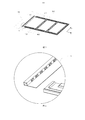
- Figure 4 is an enlarged schematic view of a portion of the backing plate A shown in Figure 3.
- FIG. 1 is a schematic structural view of a light-incident side support of a first embodiment of a backboard according to the present invention.
- the light entrance side bracket 100 includes a side wall 101, a bottom plate 102, and an air flow through groove 103.
- the light-incident side bracket 100 is integrally formed by extrusion using an aluminum material.
- the electrolytic lead-lead galvanized steel sheet may be integrally formed, which is not limited in the present invention.
- the light source 10 is of a side-in type, and the light source 10 is disposed on the inner side of the side wall 101.
- the light source 10 may be composed of a plurality of LED strips.
- the side wall 101 is connected to the bottom plate 102.
- the side wall 101 is a concentrated area of heat.
- the outer side opposite to the inner side surface of the side wall 101 is coated with a heat dissipation coating 110 to improve the heat dissipation efficiency of the side wall 101.
- the heat-dissipating coating 110 is preferably a heat-dissipating lacquer or a radiant heat-dissipating material. Of course, other heat-dissipating materials may be used, which is not limited in the present invention.
- the heat dissipation coating 110 may be applied to the outside of the entire light-incident side bracket 100. In one example, the heat dissipating material may be applied to the light entrance side bracket 100 by spraying or brushing.
- the light-incident side bracket of the embodiment of the invention directly sets the light source on the side wall of the light-incident side bracket, and protrudes on the outer side surface of the side wall to form an air flow passage groove, thereby saving cost and improving heat dissipation efficiency.
- FIG. 2 is a schematic structural view of the light-incident side bracket of the second embodiment of the backboard of the present invention.
- the light-incident side bracket 200 includes a side wall 201, a bottom plate 202, and an air flow passage groove 203.
- the light-incident side bracket 200 is integrally formed by extrusion using an aluminum material.
- the electrolytic lead-lead galvanized steel sheet may be integrally formed, which is not limited in the present invention.
- the light source 20 is of a straight-in type, and the light source 20 is disposed on an inner side of the bottom plate 202.
- the light source 20 may be composed of a plurality of LED strips.
- the bottom plate 202 is connected to the side wall 201.
- the bottom plate 202 is a hot concentrated area, and the outer side opposite to the inner side surface of the bottom plate 202 is coated with a heat dissipation coating 210 to improve the heat dissipation efficiency of the bottom plate 202.
- the heat-dissipating coating layer 210 is preferably a heat-dissipating lacquer or a radiant heat-dissipating material. Of course, other heat-dissipating materials may be used, which are not limited in the present invention.
- the heat dissipation coating 210 may be coated on the outer side of the entire light-incident side bracket 200. In one example, the heat dissipating material may be applied to the light entrance side bracket 200 by spraying or brushing.
- the air circulation groove 203 is formed by the outer side surface of the bottom plate 202.
- the air flow passage groove 203 is closed around, and the two ends (perpendicular to the paper surface) are open to the outside atmosphere, and the external gas can be convected during the heat dissipation operation, which greatly improves the flow.
- the air flow through groove 203 is in the shape of a hollow rectangle or a hollow bow. Of course, in other embodiments, other shapes of air grooves that are open to the outside atmosphere may be used, which is not limited in the present invention.
- the light-incident side bracket of the embodiment of the invention directly sets the light source on the bottom plate of the light-incident side bracket, and protrudes on the outer side surface of the bottom plate to form an air flow passage groove, thereby saving cost and improving heat dissipation efficiency.
- FIG. 3 is a schematic structural view of a backboard of the present invention
- FIG. 4 is an enlarged schematic view of a portion of the backplane A shown in FIG.
- the backplane 300 is formed by splicing a plurality of brackets.
- the backplane 300 is composed of a plurality of minimum units 400.
- the structure of the backplane 300 is described below with a minimum unit 400 of the backplane 300.
- an x-y coordinate system is defined in the figure, wherein the x-axis is the left-right direction and the y-axis is the up-and-down direction.
- the smallest unit 400 of the backing plate 300 includes a left side bracket 401, a right side bracket 402, an upper side bracket 403, and a lower side bracket 404.
- the left side bracket 401 is a light-incident side bracket.
- the right side bracket 402 may also be a light-incident side bracket and an upper side.
- the bracket 403 may also be a light-incident side bracket or a lower bracket 404 or a light-inlet side bracket, or two or more of the left bracket 401, the right bracket 402, the upper bracket 403, and the lower bracket 404.
- the invention is not limited to the invention. Only the corresponding heat-dissipating material is applied on the light-incident side bracket to improve the heat dissipation efficiency.
- the back plate 300 is formed by splicing a plurality of brackets, so each bracket is small in volume relative to the integrated back plate, and only needs to be applied to the corresponding light-incident side bracket when applying the heat-dissipating material. Coating is carried out without the need for a large fixing mechanism for fixing, resulting in a reduction in cost.
- the embodiment of the invention further provides a backlight module, which comprises the backboard described in the above embodiments.
- the back plate is formed by splicing a plurality of brackets, and the light source is disposed on the light-incident side bracket of the backboard, and an airflow through slot is disposed on the light-incident side bracket, thereby saving cost. Improve heat dissipation efficiency.
- an embodiment of the present invention further provides a liquid crystal display device including a liquid crystal panel and the backlight module described in the above embodiments.
Landscapes
- Physics & Mathematics (AREA)
- General Physics & Mathematics (AREA)
- Engineering & Computer Science (AREA)
- Theoretical Computer Science (AREA)
- Nonlinear Science (AREA)
- Mathematical Physics (AREA)
- Chemical & Material Sciences (AREA)
- Crystallography & Structural Chemistry (AREA)
- Optics & Photonics (AREA)
- Planar Illumination Modules (AREA)
- Liquid Crystal (AREA)
- Arrangement Of Elements, Cooling, Sealing, Or The Like Of Lighting Devices (AREA)
Description
【技术领域】
本发明涉及液晶制造技术领域,特别是涉及一种液晶显示装置及其背光模组和背板。
【背景技术】
液晶显示装置一般包括叠合设置的背光模组和液晶显示面板,液晶显示面板本身不会发光,需要背光模组为其提供背光进行显示。发光二极管(LED)作为典型的点光源装置,往往作为关键零组件应用于背光模组。其中较常用的即是采用多个发光二极管作为点光源阵列设置于印刷电路板(PCB)表面组成发光二极管灯条(Light
Bar)。多个发光二极管在该印刷电路板的驱动作用下发光,进而形成条形线光源,然后通过背光模组的导光板(LGP)改变光的出射方向,得到均匀的面光源。光源工作时发热较大,需要相应的散热装置。
现有技术中,将光源设置在金属基印刷电路板上,通过金属基印刷电路板与背板的接触进行热传导散热,这种散热方式不能将热量迅速传递到背板上,散热效果不佳,且金属基印刷电路板材料成本高。
【发明内容】
本发明实施例主要解决的技术问题是提供一种液晶显示装置及其背光模组和背板,能够节约成本,提升散热效果。
为解决上述技术问题,本发明实施例采用的一个技术方案是:提供一种用于背光模组的背板,其包括用于设置光源的入光侧支架,入光侧支架包括用于为光源散热的气流通槽以及相连接的侧壁和底板;其中,入光侧支架为铝材料挤压成型。
其中,光源设置于侧壁内侧面上,气流通槽由侧壁外侧面突出形成。
其中,光源设置于底板内侧面上,气流通槽由底板外侧面突出形成。
其中,气流通槽呈空心矩形或空心弓形状,四周封闭,两端与外界大气相通。
其中,背板由多个支架拼接而成,背板包括:左侧支架、右侧支架、上侧支架以及下侧支架,其中,左侧支架、右侧支架、上侧支架以及下侧支架中的至少一者为入光侧支架。
其中,入光侧支架上设置光源的部分涂布有散热材料,或者入光侧支架整体涂布有散热材料。
其中,散热材料为散热漆或辐射散热材料,散热材料通过喷涂或者刷涂的方式涂覆在入光侧支架上。
为解决上述技术问题,本发明实施例采用的另一个技术方案是:提供一种背光模组,其包括背板,背板包括用于设置背光模组的光源的入光侧支架,入光侧支架包括用于为光源散热的气流通槽以及相连接的侧壁和底板;其中,入光侧支架为铝材料挤压成型。
其中,气流通槽呈空心矩形或空心弓形状,四周封闭,两端与外界大气相通。
为解决上述技术问题,本发明实施例采用的又一个技术方案是:提供一种液晶显示装置,其包括液晶面板以及如前所述的背光模组。
本发明实施例的背板通过将光源直接设置在入光侧支架上,并且在入光侧支架的侧壁或底板设置气流通槽,能够节约成本,提升散热效果。
【附图说明】
图1是本发明背板的第一实施例的入光侧支架结构示意图;
图2是本发明背板的第二实施例的入光侧支架结构示意图;
图3是本发明的背板的结构示意图;
图4是图3所示的背板A部分的放大示意图。
【具体实施方式】
下面将结合本发明实施例中的附图,对本发明实施例中的技术方案进行清楚、完整地描述,显然,所描述的实施例仅是本发明的一部分实施例,而不是全部的实施例。基于本发明中的实施例,本领域普通技术人员在没有做出创造性劳动前提下所获得的所有其他实施例,都属于本发明保护的范围。
请参阅图1,图1是本发明背板的第一实施例的入光侧支架结构示意图。为了清楚显示,图中示出了光源10。入光侧支架100包括侧壁101、底板102以及气流通槽103。入光侧支架100采用铝材料挤压一体成型。当然,在其他备选实施例中,也可以采用电解亚铅镀锌钢板一体成型,本发明对此不作限定。
在本实施例中,光源10为侧入式,光源10设置于侧壁101的内侧面上,在一个具体实例中,该光源10可由多个LED灯条组成。
侧壁101与底板102相连,侧壁101是热的集中区域,与侧壁101内侧面相对的外侧面涂有散热涂层110,以提高侧壁101的散热效率。在本实施例中,散热涂层110优选采用散热漆或辐射散热材料,当然,也可以是其他的具有散热特性的材料,本发明对此不作限定。进一步地,为了更好地提升散热效率,还可以在整个入光侧支架100的外侧涂覆散热涂层110。在一个实例中,散热材料可以通过喷涂或者刷涂的方式涂覆在入光侧支架100上。
气流通槽103由侧壁101外侧面突出形成,该气流通槽103四周封闭,两端(垂直于纸面的方向)与外界大气相通,在进行散热工作时形成外部气体可对流,极大地提高了入光侧支架100的散热效率。在本实施例中,气流通槽103为空心矩形或空心弓形状,当然,在其他实施例中,也可以采用与外界大气相通的其他形状气槽,本发明对此不作限定。
本发明实施例的入光侧支架通过将光源直接设置于入光侧支架的侧壁上,并在侧壁的外侧面突出形成气流通槽,节约了成本,提升了散热效率。
请参阅图2,图2是本发明背板的第二实施例的入光侧支架结构示意图。为了清楚显示,图中示出了光源20。入光侧支架200包括侧壁201、底板202以及气流通槽203。入光侧支架200采用铝材料挤压一体成型。当然,在其他备选实施例中,也可以采用电解亚铅镀锌钢板一体成型,本发明对此不作限定。
在本实施例中,光源20为直入式,光源20设置于底板202的内侧面上,在一个具体实例中,该光源20可由多个LED灯条组成。
底板202和侧壁201相连,底板202是热的集中区域,与底板202内侧面相对的外侧面涂有散热涂层210,以提高底板202的散热效率。在本实施例中,散热涂层210优选采用散热漆或辐射散热材料,当然,也可以是其他的具有散热特性的材料,本发明对此不作限定。进一步地,为了更好地提升散热效率,还可以在整个入光侧支架200的外侧涂覆散热涂层210。在一个实例中,散热材料可以通过喷涂或者刷涂的方式涂覆在入光侧支架200上。
气流通槽203由底板202外侧面突出形成,该气流通槽203四周封闭,两端(垂直于纸面的方向)与外界大气相通,在进行散热工作时形成外部气体可对流,极大地提高了入光侧支架200的散热效率。在本实施例中,气流通槽203为空心矩形或空心弓形状,当然,在其他实施例中,也可以采用与外界大气相通的其他形状气槽,本发明对此不作限定。
本发明实施例的入光侧支架通过将光源直接设置于入光侧支架的底板上,并在底板的外侧面突出形成气流通槽,节约了成本,提升了散热效率。
请参阅图3和图4,图3是本发明的背板的结构示意图,图4是图3所示的背板A部分的放大示意图。背板300由多个支架拼接而成,背板300由若干个最小单元400组成,下面以背板300的一个最小单元400来说明该背板300的结构。为了说明各元件的位置关系,本图中定义了x-y坐标系,其中x轴为左右方向,y轴为上下方向。
背板300的最小单元400包括左侧支架401、右侧支架402、上侧支架403以及下侧支架404。在本实施例中,如图4所示,左侧支架401为入光侧支架,当然,在其他实施例中,根据光源设置的不同,右侧支架402也可以为入光侧支架、上侧支架403也可以为入光侧支架或者下侧支架404也可以为入光侧支架,又或者左侧支架401、右侧支架402、上侧支架403以及下侧支架404中的两个或多个组合为入光侧支架,本发明对此不作限定。只需对应的在入光侧支架上涂布散热材料,以提高散热效率。
进一步地,在本实施例中,背板300由多个支架拼接而成,因而每个支架相对于一体式背板体积较小,在涂覆散热材料时,只需对相应的入光侧支架进行涂覆,不需大型固定机构来固定,使得成本降低。
本发明实施例进一步提供一种背光模组,该背光模组包括上述实施例中所述的背板。背板由多个支架拼接而成,将光源设置于背板的入光侧支架上,并在入光侧支架上设置气流通槽,能够节约成本
,提升散热效率。
此外,本发明实施例还提供一种液晶显示装置,其包括液晶面板和上述实施例中所述的背光模组。
以上所述仅为本发明的实施方式,并非因此限制本发明的专利范围,凡是利用本发明说明书及附图内容所作的等效结构或等效流程变换,或直接或间接运用在其他相关的技术领域,均同理包括在本发明的专利保护范围内。
Claims (10)
- 一种用于背光模组的背板,其中,所述背板包括用于设置所述背光模组的光源的入光侧支架,所述入光侧支架包括用于为所述光源散热的气流通槽以及相连接的侧壁和底板;其中,所述入光侧支架为铝材料挤压成型。
- 根据权利要求1所述的背板,其中,所述光源设置于所述侧壁内侧面上,所述气流通槽由所述侧壁外侧面突出形成。
- 根据权利要求1所述的背板,其中,所述光源设置于所述底板内侧面上,所述气流通槽由所述底板外侧面突出形成。
- 根据权利要求3所述的背板,其中,所述气流通槽呈空心矩形或空心弓形状,四周封闭,两端与外界大气相通。
- 根据权利要求1所述的背板,其中,所述背板由多个支架拼接而成,所述背板包括:左侧支架、右侧支架、上侧支架以及下侧支架,其中,所述左侧支架、所述右侧支架、所述上侧支架以及所述下侧支架中的至少一者为所述入光侧支架。
- 根据权利要求1所述的背板,其中,所述入光侧支架上设置所述光源的部分涂布有散热材料,或者所述入光侧支架上整体涂布有散热材料。
- 根据权利要求6所述的背板,其中,所述散热材料为散热漆或辐射散热材料,所述散热材料通过喷涂或者刷涂的方式涂覆在所述入光侧支架上。
- 一种背光模组,其中,所述背光模组包括背板,所述背板包括用于设置所述背光模组的光源的入光侧支架,所述入光侧支架包括用于为所述光源散热的气流通槽以及相连接的侧壁和底板;其中,所述入光侧支架为铝材料挤压成型。
- 根据权利要求8所述的背光模组,其中,所述气流通槽呈空心矩形或空心弓形状,四周封闭,两端与外界大气相通。
- 一种液晶显示装置,其中,包括液晶面板和根据权利要求8所述的背光模组。
Priority Applications (1)
| Application Number | Priority Date | Filing Date | Title |
|---|---|---|---|
| US13/641,408 US20140063787A1 (en) | 2012-08-28 | 2012-09-06 | Liquid Crystal Device, Backlight Module, and Backplane |
Applications Claiming Priority (2)
| Application Number | Priority Date | Filing Date | Title |
|---|---|---|---|
| CN201210310364.0 | 2012-08-28 | ||
| CN2012103103640A CN102901006A (zh) | 2012-08-28 | 2012-08-28 | 液晶显示装置及其背光模组和背板 |
Publications (1)
| Publication Number | Publication Date |
|---|---|
| WO2014032321A1 true WO2014032321A1 (zh) | 2014-03-06 |
Family
ID=47573398
Family Applications (1)
| Application Number | Title | Priority Date | Filing Date |
|---|---|---|---|
| PCT/CN2012/081049 Ceased WO2014032321A1 (zh) | 2012-08-28 | 2012-09-06 | 液晶显示装置及其背光模组和背板 |
Country Status (3)
| Country | Link |
|---|---|
| US (1) | US20140063787A1 (zh) |
| CN (1) | CN102901006A (zh) |
| WO (1) | WO2014032321A1 (zh) |
Families Citing this family (7)
| Publication number | Priority date | Publication date | Assignee | Title |
|---|---|---|---|---|
| US20130128513A1 (en) * | 2011-11-18 | 2013-05-23 | Shenzhen China Star Optoelectronics Technology Co., Ltd. | Mold for Back Frame and Bracing Piece, Method for Manufacturing Back Frame, and Backlight System |
| CN105202424B (zh) | 2015-10-29 | 2018-03-02 | 京东方光科技有限公司 | 背光单元及显示装置 |
| CN107037631A (zh) * | 2016-12-02 | 2017-08-11 | 深圳市华星光电技术有限公司 | 液晶显示器及其背光模组 |
| CN109283743A (zh) * | 2018-10-26 | 2019-01-29 | 蚌埠国显科技有限公司 | 一种液晶显示模组 |
| CN109283742B (zh) * | 2018-10-26 | 2024-08-09 | 蚌埠国显科技有限公司 | 一种led灯位于背板外侧的液晶显示模组 |
| CN109270721B (zh) * | 2018-10-26 | 2024-08-09 | 蚌埠国显科技有限公司 | 一种不易损坏的液晶显示模组 |
| CN114488614B (zh) * | 2021-12-30 | 2023-05-16 | 锐捷网络股份有限公司 | 背光模组和显示设备 |
Citations (6)
| Publication number | Priority date | Publication date | Assignee | Title |
|---|---|---|---|---|
| US20020050977A1 (en) * | 2000-11-01 | 2002-05-02 | Au Optronics Corp. | Housing for flat panel displays and method for receiving flat panel displays |
| KR100879772B1 (ko) * | 2007-09-06 | 2009-01-21 | 한성엘컴텍 주식회사 | 복수의 발광소자를 포함하는 면 발광장치 |
| CN102067018A (zh) * | 2009-06-24 | 2011-05-18 | 爱泼特光电有限公司 | 模块电路基板与框架的结合装置及使用了该结合装置的背光装置 |
| TW201127230A (en) * | 2009-10-14 | 2011-08-01 | Lg Innotek Co Ltd | Heat radiating printed circuit board and chassis assembly having the same |
| CN102352981A (zh) * | 2011-03-02 | 2012-02-15 | 友达光电股份有限公司 | 背光模块 |
| CN202351573U (zh) * | 2011-11-18 | 2012-07-25 | 深圳市华星光电技术有限公司 | 平板显示装置及立体显示装置 |
Family Cites Families (9)
| Publication number | Priority date | Publication date | Assignee | Title |
|---|---|---|---|---|
| TW594244B (en) * | 2003-02-27 | 2004-06-21 | Quanta Display Inc | Back light module |
| JP4590283B2 (ja) * | 2004-05-21 | 2010-12-01 | シャープ株式会社 | バックライトユニット及びそれを備えた液晶表示装置 |
| KR100638047B1 (ko) * | 2004-10-15 | 2006-10-23 | 엘지전자 주식회사 | 백라이트 유닛을 갖는 액정 디스플레이 |
| KR100747820B1 (ko) * | 2005-11-04 | 2007-08-08 | 엘지전자 주식회사 | 평면 디스플레이 기기의 냉각 장치 |
| CN101470298B (zh) * | 2007-12-29 | 2012-01-11 | 富士迈半导体精密工业(上海)有限公司 | 背光模组 |
| CN101949526B (zh) * | 2010-07-12 | 2012-11-14 | 深圳市华星光电技术有限公司 | 侧入式背光模块及其背板散热构造 |
| CN202082747U (zh) * | 2011-05-26 | 2011-12-21 | 深圳市华星光电技术有限公司 | 显示装置及背光模组 |
| CN102635837A (zh) * | 2012-03-29 | 2012-08-15 | 深圳市华星光电技术有限公司 | 背板及使用该背板的背光模组 |
| US8593041B1 (en) * | 2012-08-28 | 2013-11-26 | Shenzhen China Star Optoelectronics Technology Co., Ltd. | Backlight module and heatsink apparatus |
-
2012
- 2012-08-28 CN CN2012103103640A patent/CN102901006A/zh active Pending
- 2012-09-06 US US13/641,408 patent/US20140063787A1/en not_active Abandoned
- 2012-09-06 WO PCT/CN2012/081049 patent/WO2014032321A1/zh not_active Ceased
Patent Citations (6)
| Publication number | Priority date | Publication date | Assignee | Title |
|---|---|---|---|---|
| US20020050977A1 (en) * | 2000-11-01 | 2002-05-02 | Au Optronics Corp. | Housing for flat panel displays and method for receiving flat panel displays |
| KR100879772B1 (ko) * | 2007-09-06 | 2009-01-21 | 한성엘컴텍 주식회사 | 복수의 발광소자를 포함하는 면 발광장치 |
| CN102067018A (zh) * | 2009-06-24 | 2011-05-18 | 爱泼特光电有限公司 | 模块电路基板与框架的结合装置及使用了该结合装置的背光装置 |
| TW201127230A (en) * | 2009-10-14 | 2011-08-01 | Lg Innotek Co Ltd | Heat radiating printed circuit board and chassis assembly having the same |
| CN102352981A (zh) * | 2011-03-02 | 2012-02-15 | 友达光电股份有限公司 | 背光模块 |
| CN202351573U (zh) * | 2011-11-18 | 2012-07-25 | 深圳市华星光电技术有限公司 | 平板显示装置及立体显示装置 |
Also Published As
| Publication number | Publication date |
|---|---|
| US20140063787A1 (en) | 2014-03-06 |
| CN102901006A (zh) | 2013-01-30 |
Similar Documents
| Publication | Publication Date | Title |
|---|---|---|
| WO2014032321A1 (zh) | 液晶显示装置及其背光模组和背板 | |
| US7431475B2 (en) | Radiator for light emitting unit, and backlight device | |
| RU2586451C1 (ru) | Устройство отображения | |
| WO2012006820A1 (zh) | 侧入式背光模块及其背板散热构造 | |
| CN102193219B (zh) | 显示装置及其组装方法 | |
| US7391157B2 (en) | Plasma display device | |
| CN204300865U (zh) | 一种液晶显示装置及其背光模组 | |
| WO2014015506A1 (zh) | 一种背光模组及液晶显示装置 | |
| CN114488614B (zh) | 背光模组和显示设备 | |
| WO2014133296A1 (en) | Display apparatus | |
| CN105757537A (zh) | 一种背光模组及显示装置 | |
| US20250048908A1 (en) | Display panel and display module | |
| CN102913825A (zh) | 一种发光单元、背光模组及显示装置 | |
| EP2219054A1 (en) | Light emitting module and display device having the same | |
| WO2014032273A1 (zh) | 背光模组及散热装置 | |
| CN203384778U (zh) | 直下摆设而侧入光源的背光模块 | |
| KR101118917B1 (ko) | 엘이디 조명 및 백라이트 유닛용 광원장치 | |
| CN102252217A (zh) | 具有双面出光结构的背光模块及显示装置 | |
| WO2013143181A1 (zh) | 中框及液晶显示模组 | |
| WO2014019243A1 (zh) | 一种背光模组及液晶显示器 | |
| CN206819010U (zh) | 一种背光模组、显示装置及无人机系统 | |
| KR20210009716A (ko) | 디스플레이 디바이스 | |
| WO2014107891A1 (zh) | 背光模组、印刷电路板及其制造方法 | |
| WO2019127730A1 (zh) | 轻薄化的显示装置 | |
| CN104089243A (zh) | 背光模组的灯罩、背光模组以及显示装置 |
Legal Events
| Date | Code | Title | Description |
|---|---|---|---|
| WWE | Wipo information: entry into national phase |
Ref document number: 13641408 Country of ref document: US |
|
| 121 | Ep: the epo has been informed by wipo that ep was designated in this application |
Ref document number: 12883814 Country of ref document: EP Kind code of ref document: A1 |
|
| NENP | Non-entry into the national phase |
Ref country code: DE |
|
| 122 | Ep: pct application non-entry in european phase |
Ref document number: 12883814 Country of ref document: EP Kind code of ref document: A1 |