WO2014030437A1 - Curved tube for endoscope - Google Patents

Curved tube for endoscope Download PDF

Info

Publication number
WO2014030437A1
WO2014030437A1 PCT/JP2013/068050 JP2013068050W WO2014030437A1 WO 2014030437 A1 WO2014030437 A1 WO 2014030437A1 JP 2013068050 W JP2013068050 W JP 2013068050W WO 2014030437 A1 WO2014030437 A1 WO 2014030437A1
Authority
WO
WIPO (PCT)
Prior art keywords
bending
slots
slot
width
tube
Prior art date
Application number
PCT/JP2013/068050
Other languages
French (fr)
Japanese (ja)
Inventor
佐藤 栄二郎
グレゴリー コンストラム
Original Assignee
オリンパスメディカルシステムズ株式会社
Priority date (The priority date is an assumption and is not a legal conclusion. Google has not performed a legal analysis and makes no representation as to the accuracy of the date listed.)
Filing date
Publication date
Application filed by オリンパスメディカルシステムズ株式会社 filed Critical オリンパスメディカルシステムズ株式会社
Priority to EP13830266.6A priority Critical patent/EP2777476B1/en
Priority to CN201380004481.7A priority patent/CN104023616B/en
Priority to JP2013554730A priority patent/JP5537748B1/en
Publication of WO2014030437A1 publication Critical patent/WO2014030437A1/en

Links

Images

Classifications

    • FMECHANICAL ENGINEERING; LIGHTING; HEATING; WEAPONS; BLASTING
    • F16ENGINEERING ELEMENTS AND UNITS; GENERAL MEASURES FOR PRODUCING AND MAINTAINING EFFECTIVE FUNCTIONING OF MACHINES OR INSTALLATIONS; THERMAL INSULATION IN GENERAL
    • F16LPIPES; JOINTS OR FITTINGS FOR PIPES; SUPPORTS FOR PIPES, CABLES OR PROTECTIVE TUBING; MEANS FOR THERMAL INSULATION IN GENERAL
    • F16L11/00Hoses, i.e. flexible pipes
    • AHUMAN NECESSITIES
    • A61MEDICAL OR VETERINARY SCIENCE; HYGIENE
    • A61BDIAGNOSIS; SURGERY; IDENTIFICATION
    • A61B1/00Instruments for performing medical examinations of the interior of cavities or tubes of the body by visual or photographical inspection, e.g. endoscopes; Illuminating arrangements therefor
    • A61B1/005Flexible endoscopes
    • A61B1/0051Flexible endoscopes with controlled bending of insertion part
    • A61B1/0055Constructional details of insertion parts, e.g. vertebral elements
    • AHUMAN NECESSITIES
    • A61MEDICAL OR VETERINARY SCIENCE; HYGIENE
    • A61BDIAGNOSIS; SURGERY; IDENTIFICATION
    • A61B1/00Instruments for performing medical examinations of the interior of cavities or tubes of the body by visual or photographical inspection, e.g. endoscopes; Illuminating arrangements therefor
    • A61B1/005Flexible endoscopes
    • A61B1/0051Flexible endoscopes with controlled bending of insertion part
    • A61B1/0057Constructional details of force transmission elements, e.g. control wires
    • AHUMAN NECESSITIES
    • A61MEDICAL OR VETERINARY SCIENCE; HYGIENE
    • A61MDEVICES FOR INTRODUCING MEDIA INTO, OR ONTO, THE BODY; DEVICES FOR TRANSDUCING BODY MEDIA OR FOR TAKING MEDIA FROM THE BODY; DEVICES FOR PRODUCING OR ENDING SLEEP OR STUPOR
    • A61M25/00Catheters; Hollow probes
    • A61M25/01Introducing, guiding, advancing, emplacing or holding catheters
    • A61M25/0105Steering means as part of the catheter or advancing means; Markers for positioning
    • A61M25/0133Tip steering devices
    • A61M25/0138Tip steering devices having flexible regions as a result of weakened outer material, e.g. slots, slits, cuts, joints or coils

Definitions

  • the present invention relates to a bending tube for an endoscope that bends in response to an operation of an operation unit.
  • endoscopes that display a subject image in a body cavity on a screen of a display device by inserting an elongated insertion portion into the body cavity have been widely used.
  • the insertion portion includes a distal end hard portion, a bending portion, and a flexible tube portion in order from the distal end side. Has been configured.
  • the bending portion is configured to be freely bent in, for example, two vertical directions, two horizontal directions, or four vertical and horizontal directions associated with a subject image displayed on the display device.
  • the bending portion is generally configured to include a bending tube (a bending portion set) in which a plurality of joint pieces are rotatably connected by a rotation pin. An angle wire is inserted into the bending tube, and the bending portion is bent by pulling or relaxing the angle wire.
  • Patent Document 1 discloses a wire receiver (wire) for inserting an angle wire by deforming a part of the annular portion of the pipe material in the inner diameter direction of the pipe material. A technique for integrally forming a guide is disclosed.
  • the bending characteristics of the bending tube may partially change before and after the wire guide. . If the bending characteristics are partially changed in this way, it may be difficult to obtain a desired curved shape, for example, by bending the bending tube into a uniform arc shape.
  • the present invention has been made in view of the above circumstances, and an object thereof is to provide a bending tube for an endoscope that can bend the bending portion into a desired bending shape with a simple configuration.
  • An endoscope bending tube includes a cylindrical bending tube main body made of a superelastic alloy material, and the bending tube main body provided at set intervals along the longitudinal axis direction of the bending tube main body.
  • a plurality of bending slots extending in the circumferential direction
  • a wire guide forming slot extending in the circumferential direction of the bending tube body provided in a pair on the array of the plurality of bending slots
  • a wire guide formed by deforming the outer peripheral portion of the bending tube body in the inner diameter direction between the pair of wire guide forming slots, and the width of the bending slot adjacent to the wire guide It is set narrower than the width of the bending slot.
  • FIG. 1 The perspective view of an endoscope according to the first embodiment of the present invention.
  • side view of curved tube Same as above, side view partially cut away showing the main part of the bending tube
  • sectional view taken along line VV in FIG. an explanatory view showing the minimum radius of curvature of the bending tube
  • ruptured The perspective view which shows the principal part of a bending tube same as the above.
  • ruptured The perspective view which shows the principal part of a bending tube same as the above. Same as above, a side view showing a partially broken main portion of the bending tube according to the first modification.
  • bottom view showing the main part of the bending tube according to the third modification Side view showing a part of the curved tube broken away Perspective view showing the main part of the bending tube
  • FIG. 1 is a perspective view of an endoscope
  • FIG. 2 is a side view of the bending tube
  • FIG. 4 is a perspective view showing the main part of the bending tube
  • FIG. 5 is a cross-sectional view of the main part along the line VV in FIG. 1
  • FIG. 6 is an explanatory view showing the minimum radius of curvature of the bending pipe
  • FIG. It is explanatory drawing which shows the minimum curvature radius of the bending tube when not adjusting as a comparative example.
  • an endoscope 1 includes, for example, a long insertion portion 2 to be inserted into a subject, an operation portion 3 provided at the proximal end of the insertion portion 2, and the operation portion 3 side.
  • the main part is configured to include a universal cord 4 extending from the portion, an eyepiece portion 5 provided at the base end of the operation portion 3, and a connector 6 provided at the extension end of the universal cord 4. It is a so-called fiberscope.
  • the endoscope 1 can be connected to an external device (not shown) such as a light source device via a connector 6.
  • the configuration of the endoscope 1 will be described by taking the configuration of a fiberscope as an example.
  • the endoscope 1 to which the present invention is applied is not limited to a fiber scope. .
  • the insertion portion 2 has a distal end hard portion 11 located on the distal end side, a bending portion 12 provided continuously with the proximal end of the distal end hard portion 11, and a flexibility provided continuously with the proximal end of the bending portion 12.
  • the main part is comprised including the flexible tube part 13.
  • an observation lens, an illumination lens, and the like are provided in the distal end hard portion 11.
  • the bending portion 12 can be bent in two directions, for example, up and down, when the bending lever 14 provided in the operation portion 3 is rotated.
  • the operation unit 3 is provided with a treatment instrument insertion port 15.
  • the treatment instrument insertion port 15 communicates with the proximal end side of a treatment instrument insertion channel 16 (see FIG. 5) inserted into the insertion portion 2. Thereby, the treatment instrument inserted into the treatment instrument insertion port 15 is guided to the distal end side of the insertion portion 2 via the treatment instrument insertion channel 16, and from the opening formed on the distal end surface of the distal end rigid portion 11, It is possible to project into the subject.
  • the light guide 17 for transmitting the illumination light to the illumination lens described above and the observation lens described above are condensed.
  • An image guide 18 that transmits an optical image in the subject to the eyepiece 5, angle wires 19a and 19b for bending the bending portion 12 in conjunction with the turning operation of the bending lever 14, etc. (FIG. 5). See) is inserted.
  • the light guide 17 is also inserted into the universal cord 4 and the connector 6.
  • the bending portion 12 is configured to include a first bending portion 12a located on the distal end side and a second bending portion 12b provided continuously with the proximal end of the first bending portion 12a.
  • the first and second curved portions 12a and 12b have different minimum radii of curvature during bending, and the minimum radius of curvature of the first curved portion 12a is smaller than the minimum radius of curvature of the second curved portion 12b. Is set.
  • the bending portion 12 is not limited to one having a configuration in which the minimum radius of curvature at the time of bending is different in two steps on the distal end side and the proximal end side, for example, from the distal end side to the proximal end side.
  • the structure may have a uniform minimum radius of curvature.
  • the bending portion 12 is made of, for example, a bending tube 30 mainly composed of a cylindrical bending tube main body 31 made of a superelastic alloy material, and a resin-made covering the periphery of the bending tube 30. And an outer skin 32.
  • the superelastic alloy material constituting the bending tube main body 31 include Ni—Ti (nickel titanium), titanium alloy, ⁇ titanium, pure titanium, 64 titanium, A7075, and the like. Is not to be done.
  • the bending tube main body 31 is provided with a plurality of bending slots formed by, for example, laser processing or the like, which are partially arc-shaped elongated holes extending in the circumferential direction of the bending tube main body 31.
  • the bending tube main body 31 includes the bending tube main body 31 from the upper side to the lower side in the bending direction.
  • a plurality of bending slots 33a extending and a plurality of bending slots 33b extending upward from the lower side in the bending direction of the bending tube main body 31 are provided.
  • each of the bending slots 33a and 33b is constituted by a partial arc-shaped long hole having an axially symmetric shape with respect to the longitudinal axis O.
  • the bending slots 33a are arranged in a row for each preset pitch P1 in the first area A1 set on the bending tube body 31 corresponding to the first bending portion 12a. Further, in the second region A2 set on the bending tube main body 31 corresponding to the second bending portion 12b, they are arranged in a line for each preset pitch P2 (where P1 ⁇ P2). .
  • the respective bending slots 33b are arranged in a line for each pitch P1 in the first region A1 set on the bending tube main body 31, and further, the second region set on the bending tube main body 31. In A2, they are arranged in a line for every pitch P2.
  • the bending slot 33b is arranged offset from the bending slot 33a by a half pitch (P1 / 2) in the longitudinal axis O direction of the bending tube main body 31.
  • the bending slot 33b is disposed in a state offset from the bending slot 33a by a half pitch (P2 / 2) in the longitudinal axis O direction of the bending tube main body 31. Then, by being offset in the direction of the longitudinal axis O in this way, each bending slot 33a and each bending slot 33b are arranged on the bending tube main body 31 without interfering with each other.
  • the specific bending slots 33a paired adjacent to each other are also used as wire guide forming slots (hereinafter, these specific bending slots will be described below).
  • 33a will be described with a symbol “′” in order to distinguish it from other bending slots 33a).
  • a part of the outer peripheral portion on the UP side of the bending tube main body 31 is deformed in the inner diameter direction, and this deformation causes the bending tube 30 to have the angle wire 19a.
  • a wire guide 35a that is inserted in the middle is formed (for example, see FIGS. 3 and 4).
  • the specific bending slots 33b that are paired adjacent to each other are also used as wire guide forming slots (hereinafter, these specific bending slots are used).
  • the slot 33b will be described with a symbol “′” attached to it in order to distinguish it from the other bending slots 33b.)
  • the DOWN of the bending tube main body 31 will be described. A part of the outer peripheral portion on the side is deformed in the inner diameter direction, and by this deformation, a wire guide 35b through which the middle of the angle wire 19b is inserted is formed in the bending tube 30.
  • Each of the wire guides 35a and 35b is set, for example, by positioning the bending tube main body 31 on a predetermined processing jig, and corresponding portions on the bending tube main body 31 (between a pair of bending slots 33a ′ and It is formed by performing a heat treatment such as immersing in a high-temperature salt for a predetermined time in a state in which a pair of bending slots 33b ′) is pressed in the inner diameter direction by a processing jig.
  • the minimum radius of curvature R when the bending tube 30 is bent toward the UP side mainly depends on the bending slot 33a (and 33a ′), and the minimum radius when the bending portion 30 is bent toward the DOWN side.
  • the radius of curvature R is defined mainly depending on the bending slot 33b (and 33b ′).
  • the bending in the bending slot 33a (33a ′) of the bending tube body 31 forms the bending slot 33a (33a ′).
  • the maximum bending angle ⁇ for each pitch P1 in the bending slot 33a (33a ′) of the bending tube body 31 is basically defined by the width of the bending slot 33a (33a ′).
  • the wall portions before and after forming the specific bending slot 33a 'that also serves as the wire guide forming slot are stepped. Accordingly, when the width of the specific bending slot 33a ′ is the same as the width of the other bending slot 33a, the timing at which the front and rear wall portions of the specific bending slot 33a ′ come into contact with each other is It is later than the timing at which the front and rear wall portions of the slot 33a abut. In other words, when the widths are the same, for example, as shown in FIG.
  • the bending angle ⁇ 2 in the specific bending slot 33a ′ becomes larger than the bending angle ⁇ 1 in the other bending slots 33a, and the result As described above, the minimum curvature radius R2 in the predetermined section before and after the specific bending slot 33a ′ is relatively smaller than the minimum curvature radius R1 in the predetermined section before and after the other bending slot 33a.
  • a specific bending angle ⁇ 2 in a specific bending slot 33a ′ is specified to match a bending angle ⁇ 1 in another bending slot 33a.
  • the width H2 of the bending slot 33a ′ is adjusted to be relatively narrower than the width H1 of the other bending slots 33a.
  • the same adjustment is made for the width H2 of the slot 33b '.
  • the plurality of bending slots 33a (and so on) that are provided at set intervals along the longitudinal axis O direction of the cylindrical bending tube body 31 and extend in the circumferential direction of the bending tube body 31.
  • Wire guides 35a and 35b formed by deforming the outer peripheral portion of the bending tube body 31 in the inner diameter direction between the pair of wire guide forming slots and the bending slot 33a ′ (and the bending slot 33b ′);
  • the width H2 of the other bending slots 33a and 33b By set relatively smaller than H1, with a simple configuration, the bending portion 12 (the bending tube 30) can be bent operate in a desired curved shape.
  • the width of the bending slot (specific bending slot 33a'33b ') adjacent to the wire guides 35a and 35b.
  • the specific bending slots 33a ′ and 33b ′ are also used as the wire guide forming slots, so that the wire guides 35a and 35b can be formed without increasing the number of slots. It can form integrally, and the structure of the bending tube 30 can be simplified more.
  • FIGS. 8 and 9 relate to the second embodiment of the present invention
  • FIG. 8 is a side view showing a part of the bending tube in a partially broken state
  • FIG. 9 is a perspective view showing the part of the bending tube. is there.
  • This embodiment is mainly different from the first embodiment described above in that the wire guide forming slot is provided separately from the bending slots 33a and 33b.
  • a same sign is attached
  • the UP-side configuration and the DOWN-side configuration of the bending tube 30 are substantially the same configuration, in this embodiment, the UP-side configuration will be mainly described, and the description of the DOWN-side configuration will be omitted as appropriate. To do.
  • a pair of specific bending slots 33a ′ among a plurality of bending slots 33a is used to form a pair of wire guides.
  • a slot 34a is provided.
  • a part of the outer peripheral portion of the bending tube main body 31 is deformed in the inner diameter direction between the pair of wire guide forming slots 34a, and the middle of the angle wire 19a is inserted into the bending tube 30 by this deformation.
  • a wire guide 35a is formed.
  • the rigidity of the bending tube body 31 in the portion where the wire guide forming slots 34a and 34b are provided is superelastic alloy. However, it is partially reduced. Such a partial reduction in rigidity also affects the bending characteristics of the bending tube 30.
  • the width H3 of the specific bending slots 33a ′ and 33b ′ adjacent to the wire guide forming slots 34a and 34b is relatively larger than the width H1 of the other bending slots 33a and 33b. It is set narrowly, and the bending characteristics of the bending tube 30 are made uniform by adjusting the width H3.
  • the width H4 of the wire guide forming slots 34a and 34b is set narrower than the widths H1 and H3. Further, the extending lengths of the wire guide forming slots 34a and 34b are set to be as short as possible as compared with the bending slots 33a and 33b within a range that does not hinder the formation of the wire guides 35a and 35b. It is desirable.
  • FIGS. 10 and 11 relate to a third embodiment of the present invention
  • FIG. 10 is a side view showing a part of the bending tube in a partially broken view
  • FIG. 11 is a perspective view showing the part of the bending tube. is there.
  • This embodiment is mainly different from the first embodiment described above in that the wire guide forming slot is provided separately from the bending slots 33a and 33b.
  • a same sign is attached
  • the UP-side configuration and the DOWN-side configuration of the bending tube 30 are substantially the same configuration, in this embodiment, the UP-side configuration will be mainly described, and the description of the DOWN-side configuration will be omitted as appropriate. To do.
  • a pair of wire guide forming slots is formed at a position sandwiching a specific bending slot 33a ′ among the plurality of bending slots 33a. 34a is provided.
  • a part of the outer peripheral portion of the bending tube main body 31 is deformed in the inner diameter direction between the pair of wire guide forming slots 34a, and the middle of the angle wire 19a is inserted into the bending tube 30 by this deformation.
  • a wire guide 35a is formed.
  • the rigidity of the bending tube body 31 in the portion where the wire guide forming slots 34a and 34b are provided is a superelastic alloy. Because of this, it is partially reduced. Such a partial reduction in rigidity also affects the bending characteristics of the bending tube 30.
  • the contact positions of the front and rear side walls of the specific bending slots 33a ′ and 33b ′ are lower than the contact positions of the front and rear side walls of the other bending slots 33a and 33b. It has become. Therefore, when the width H5 of the specific bending slots 33a ′ and 33b ′ is set to be approximately the same as the width H1 of the other bending slots 33a and 33b, the walls before and after the specific bending slots 33a ′ and 33b ′ The timing at which the portions abut is later than the timing at which the front and back wall portions of the other bending slots 33a and 33b abut.
  • the width H5 of the specific bending slots 33a ′ and 33b ′ adjacent to the wire guide forming slots 34a and 34b is relatively larger than the width H1 of the other bending slots 33a and 33b.
  • the bending characteristics of the bending tube 30 are made uniform by adjusting the width H5.
  • the number of specific bending slots 33a ′ and 33b ′ that require separate width adjustment can be reduced. Play.
  • FIGS. 12 and 13 relate to a fourth embodiment of the present invention
  • FIG. 12 is a side view showing a cutaway part of the main part of the bending tube
  • FIG. 13 is a perspective view showing the main part of the bending pipe. is there.
  • This embodiment is mainly different from the first embodiment described above in that one of the paired wire guide forming slots is also used as the bending slots 33a and 33b and the other is provided separately. .
  • a same sign is attached
  • the UP-side configuration and the DOWN-side configuration of the bending tube 30 are substantially the same configuration, in this embodiment, the UP-side configuration will be mainly described, and the description of the DOWN-side configuration will be omitted as appropriate. To do.
  • a specific bending slot 33a ′ is also used as one of a pair of wire guide forming slots.
  • the other wire guide forming slot 34a (or the wire guide forming slot 34b) is provided at a position adjacent to the specific bending slot 33a '.
  • a part of the outer peripheral portion of the bending tube main body 31 is deformed in the inner diameter direction between the specific bending slot 33a ′ and the wire guide forming slot 34a.
  • a wire guide 35a through which the middle of the wire 19a is inserted is formed.
  • the front and rear wall portions are stepped. Therefore, when the width H6 of the specific bending slots 33a ′ and 33b ′ is set to be approximately the same as the width H1 of the other bending slots 33a and 33b, the walls before and after the specific bending slots 33a ′ and 33b ′ The timing at which the portions abut is later than the timing at which the front and back wall portions of the other bending slots 33a and 33b abut.
  • the rigidity of the bending tube main body 31 at the portion where the wire guide forming slots 34a and 34b are provided is partially reduced. . Such a partial reduction in rigidity also affects the bending characteristics of the bending tube 30.
  • the width H6 of the specific bending slots 33a ′ and 33b ′ adjacent to the wire guide forming slots 34a and 34b is relatively larger than the width H1 of the other bending slots 33a and 33b.
  • the bending characteristic of the bending tube 30 is made uniform by adjusting the width H6.
  • the number of specific bending slots 33a ′ and 33b ′ that require separate width adjustment can be reduced. Play.
  • FIGS. 14 and 15 relate to a fifth embodiment of the present invention.
  • FIG. 14 is a side view showing a part of the bending tube in a partially broken view.
  • FIG. 15 is a perspective view showing the part of the bending tube. is there.
  • This embodiment is mainly different from the first embodiment described above in that strain relief through holes 36a and 36b are provided at end portions of the specific bending slots 33a 'and 33b'.
  • a same sign is attached
  • the UP-side configuration and the DOWN-side configuration of the bending tube 30 are substantially the same configuration, in this embodiment, the UP-side configuration will be mainly described, and the description of the DOWN-side configuration will be omitted as appropriate. To do.
  • the end portions of the specific bending slots 33 a ′ and 33 b ′ are, for example, strain-reducing through holes 36 a, which are round holes. 36b is provided.
  • the diameters of the strain relief through holes 36a and 36b are set to be relatively larger than the width H2 of the specific bending slots 33a 'and 33b'. More specifically, in the present embodiment, the diameters of the strain relief through holes 36a and 36b are set to be equal to the width H1 of the other bending slots 33a and 33b.
  • FIG. 16 to FIG. 22 relate to a sixth embodiment of the present invention
  • FIG. 16 is a side view showing a partially broken main portion of the bending tube
  • FIG. 17 is a perspective view showing the main portion of the bending tube
  • FIG. 18 is a side view showing a partially broken main portion of the bending tube according to the first modification
  • FIG. 19 is a perspective view showing the main portion of the bending tube according to the first modification
  • FIG. 20 is a second deformation.
  • FIG. 21 is a perspective view showing the main part of the bending tube related to the second modification
  • FIG. 22 is a top view showing the main part of the bending pipe related to the third modification. It is.
  • this embodiment mainly demonstrates the structure for improving the workability
  • a same sign is attached
  • a positioning through-hole 37 penetrating from one side to the other side is provided in the side portion of the bending tube main body 31.
  • the positioning through-hole 37 is used, for example, to position the bending tube body 31 with respect to the processing jig when forming the wire guides 35a and 35b using a processing jig (not shown). is there.
  • the positioning through-holes 37 are provided at both ends of the bending slot 33b, for example.
  • the long bending tube main body 31 can be accurately positioned with respect to the processing jig.
  • the rigidity of the portion where the positioning through-hole 37 is formed is partially lowered on the bending tube main body 31.
  • the rigidity is partially reduced in this way, the amount of elastic deformation is partially increased, and the minimum bending radius of the part may be less than or equal to the bending radius defined by the width H1 of the bending slot 33a. is there.
  • the width H7 of the bending slot 33a adjacent to the positioning through-hole 37 is set. It can be set relatively narrower than the width H1 of the other bending slot 33a.
  • a part of the bending slot 33b having the positioning through-hole 37 is formed in a crank shape in order to compensate for such a decrease in torsional rigidity.
  • the positioning through-hole 37 is provided at the end of the bending slot 33b.
  • the positioning through-hole 37 is provided at the end of the bending slot 33a. Of course, it may be.
  • the present invention is not limited to the embodiments described above, and various modifications and changes are possible, and these are also within the technical scope of the present invention.
  • a specific bending slot 33b 'that forms a pair among the plurality of bending slots 33b is also used as a wire guide forming slot. It is also possible to form the wire guide 35b. With this configuration, the wire guides 35a and 35b can be pressed at the same position on the UP side and the DOWN side in the longitudinal axis O direction of the bending tube main body 31, so that it is difficult to tilt the processing jig and the bending tube main body 31 during pressing. can do.
  • description is abbreviate
  • the present invention is not limited to this, and for example, as shown in FIG.
  • the present invention can also be applied to the bending tube 30 that can be bent in the left and right directions.
  • the width can also be adjusted for a specific bending slot among the bending slots 33c and 33d corresponding to the bending in the left-right direction.

Abstract

A curved tube (30) is equipped with the following: a plurality of first curving slots (33a) that are provided at set intervals along a longitudinal axis (O) direction of a cylindrical curved tube body (31) and that extend in the circumferential direction of the curved tube body (31); wire guide-forming slots (first curving slots (33a')) provided forming a pair with respect to the arrangement of the plurality of first curving slots (33a) and extending in the peripheral direction of the curved tube body (31); and a wire guide (35a) formed by deforming an outer peripheral part of the curved tube body (31) in the inner radial direction between the wire guide forming-slots forming a pair. The curved tube (30) wherein the width (H2) of the curving slots (33a') adjacent to the wire guide (35a) is set to be relatively narrower than the width (H1) of the other curving slots (33a).

Description

内視鏡用湾曲管Endoscope bending tube
 本発明は、操作部の操作に応じて湾曲動作する内視鏡用湾曲管に関する。 The present invention relates to a bending tube for an endoscope that bends in response to an operation of an operation unit.
 従来、細長の挿入部を体腔内に挿入することによって、体腔内の被写体像を表示装置の画面上に表示させる内視鏡が広く利用されている。この種の内視鏡のうち、例えば、挿入部が可撓性を有する軟性内視鏡において、挿入部は、先端側から順に、先端硬質部、湾曲部、及び、可撓管部が連設されて構成されている。 Conventionally, endoscopes that display a subject image in a body cavity on a screen of a display device by inserting an elongated insertion portion into the body cavity have been widely used. Among these types of endoscopes, for example, in a flexible endoscope having an insertion portion that is flexible, the insertion portion includes a distal end hard portion, a bending portion, and a flexible tube portion in order from the distal end side. Has been configured.
 湾曲部は、例えば、表示装置に表示された被写体像に対応付けられた上下の2方向、左右の2方向、或いは、上下左右の4方向に湾曲自在に構成される。このような湾曲動作を可能とするため、一般に、湾曲部は、複数の関節駒を回動ピンによって回動自在に連結した湾曲管(湾曲部組)を備えて構成されている。湾曲管内には、アングルワイヤが挿通され、このアングルワイヤを牽引或いは弛緩させることにより、湾曲部は湾曲動作される。 The bending portion is configured to be freely bent in, for example, two vertical directions, two horizontal directions, or four vertical and horizontal directions associated with a subject image displayed on the display device. In order to enable such a bending operation, the bending portion is generally configured to include a bending tube (a bending portion set) in which a plurality of joint pieces are rotatably connected by a rotation pin. An angle wire is inserted into the bending tube, and the bending portion is bent by pulling or relaxing the angle wire.
 また、近年においては、関節駒及び回動ピンを用いない簡易な構成の湾曲管として、超弾性合金材を用いた湾曲管が提案されている。この種の湾曲管は、例えば、特許文献1に開示されているように、円筒状のパイプ材(湾曲管本体)に、レーザ加工等を用いて複数のスロットを設けることにより構成される。さらに、湾曲管の構成をより簡素化するため、特許文献1には、パイプ材の環状部の一部をパイプ材の内径方向に変形させることにより、アングルワイヤを挿通するためのワイヤ受け(ワイヤガイド)を一体形成する技術が開示されている。 Further, in recent years, a bending tube using a superelastic alloy material has been proposed as a bending tube having a simple configuration that does not use a joint piece and a rotating pin. For example, as disclosed in Patent Document 1, this type of curved tube is configured by providing a plurality of slots in a cylindrical pipe material (curved tube main body) using laser processing or the like. Furthermore, in order to further simplify the configuration of the bending tube, Patent Document 1 discloses a wire receiver (wire) for inserting an angle wire by deforming a part of the annular portion of the pipe material in the inner diameter direction of the pipe material. A technique for integrally forming a guide is disclosed.
 しかしながら、上述の特許文献1に開示された技術のように、湾曲管本体にワイヤガイドを一体形成した場合、当該ワイヤガイドの前後等において、湾曲管の湾曲特性が部分的に変化する場合がある。そして、このように湾曲特性が部分的に変化すると、例えば湾曲管を均一な円弧状に湾曲させる等、所望の湾曲形状を得ることが困難となる虞がある。 However, when the wire guide is integrally formed on the bending tube main body as in the technique disclosed in Patent Document 1 described above, the bending characteristics of the bending tube may partially change before and after the wire guide. . If the bending characteristics are partially changed in this way, it may be difficult to obtain a desired curved shape, for example, by bending the bending tube into a uniform arc shape.
 本発明は上記事情に鑑みてなされたもので、簡単な構成により、湾曲部を所望の湾曲形状に湾曲動作させることができる内視鏡用湾曲管を提供することを目的とする。 The present invention has been made in view of the above circumstances, and an object thereof is to provide a bending tube for an endoscope that can bend the bending portion into a desired bending shape with a simple configuration.
 本発明の一態様による内視鏡用湾曲管は、超弾性合金材からなる円筒状の湾曲管本体と、前記湾曲管本体の長手軸方向に沿って設定間隔毎に設けられた前記湾曲管本体の周方向に延在する複数の湾曲用スロットと、前記複数の湾曲用スロットの配列上に対をなして設けられた前記湾曲管本体の周方向に延在するワイヤガイド形成用スロットと、前記対をなすワイヤガイド形成用スロット間において前記湾曲管本体の外周部を内径方向に変形させて形成したワイヤガイドと、を具備し、前記ワイヤガイドに近接する前記湾曲用スロットの幅を、他の前記湾曲用スロットの幅よりも狭く設定したものである。 An endoscope bending tube according to an aspect of the present invention includes a cylindrical bending tube main body made of a superelastic alloy material, and the bending tube main body provided at set intervals along the longitudinal axis direction of the bending tube main body. A plurality of bending slots extending in the circumferential direction, a wire guide forming slot extending in the circumferential direction of the bending tube body provided in a pair on the array of the plurality of bending slots, A wire guide formed by deforming the outer peripheral portion of the bending tube body in the inner diameter direction between the pair of wire guide forming slots, and the width of the bending slot adjacent to the wire guide It is set narrower than the width of the bending slot.
本発明の第1の実施形態に係わり、内視鏡の斜視図The perspective view of an endoscope according to the first embodiment of the present invention. 同上、湾曲管の側面図Same as above, side view of curved tube 同上、湾曲管の要部を一部破断して示す側面図Same as above, side view partially cut away showing the main part of the bending tube 同上、湾曲管の要部を示す斜視図The perspective view which shows the principal part of a bending tube same as the above. 同上、図1のV-V線に沿う要部断面図Same as above, sectional view taken along line VV in FIG. 同上、湾曲管の最小曲率半径を示す説明図As above, an explanatory view showing the minimum radius of curvature of the bending tube 同上、スロット幅を調整しない場合の湾曲管の最小曲率半径を比較例として示す説明図As above, an explanatory view showing, as a comparative example, the minimum curvature radius of the bending tube when the slot width is not adjusted 本発明の第2の実施形態に係わり、湾曲管の要部を一部破断して示す側面図The side view which concerns on the 2nd Embodiment of this invention and shows the principal part of a bending tube partially fractured | ruptured 同上、湾曲管の要部を示す斜視図The perspective view which shows the principal part of a bending tube same as the above. 本発明の第3の実施形態に係わり、湾曲管の要部を一部破断して示す側面図The side view which concerns on the 3rd Embodiment of this invention, and shows the principal part of a bending tube partially fractured | ruptured 同上、湾曲管の要部を示す斜視図The perspective view which shows the principal part of a bending tube same as the above. 本発明の第4の実施形態に係わり、湾曲管の要部を一部切断して示す側面図The side view which concerns on the 4th Embodiment of this invention and cut | disconnects and shows the principal part of a bending tube. 同上、湾曲管の要部を示す斜視図The perspective view which shows the principal part of a bending tube same as the above. 本発明の第5の実施形態に係わり、湾曲管の要部を一部破断して示す側面図The side view which concerns on the 5th Embodiment of this invention, and shows the principal part of a bending tube partially fractured | ruptured 同上、湾曲管の要部を示す斜視図The perspective view which shows the principal part of a bending tube same as the above. 本発明の第6の実施形態に係わり、湾曲管の要部を一部破断して示す側面図The side view which concerns on the 6th Embodiment of this invention and shows the principal part of a bending tube partially fractured | ruptured 同上、湾曲管の要部を示す斜視図The perspective view which shows the principal part of a bending tube same as the above. 同上、第1変形例に係わり湾曲管の要部を一部破断して示す側面図Same as above, a side view showing a partially broken main portion of the bending tube according to the first modification. 同上、第1変形例に係わり湾曲管の要部を示す斜視図The perspective view which shows the principal part of a bending pipe concerning a 1st modification as above. 同上、第2変形例に係わり湾曲管の要部を示す底面図As above, a bottom view showing the main part of the bending tube according to the second modification. 同上、第2変形例に係わり湾曲管の要部を示す斜視図The perspective view which shows the principal part of a bending pipe concerning a 2nd modification as above. 同上、第3変形例に係わり湾曲管の要部を示す底面図Same as above, bottom view showing the main part of the bending tube according to the third modification 湾曲管の一部を破断して示す側面図Side view showing a part of the curved tube broken away 湾曲管の要部を示す斜視図Perspective view showing the main part of the bending tube 湾曲管の要部を示す側面図Side view showing the main part of the bending tube
 以下、図面を参照して本発明の形態を説明する。図面は本発明の第1の実施形態に係わり、図1は内視鏡の斜視図、図2は湾曲管の側面図、図3は湾曲管の要部を一部破断して示す側面図、図4は湾曲管の要部を示す斜視図、図5は図1のV-V線に沿う要部断面図、図6は湾曲管の最小曲率半径を示す説明図、図7はスロット幅を調整しない場合の湾曲管の最小曲率半径を比較例として示す説明図である。 Hereinafter, embodiments of the present invention will be described with reference to the drawings. The drawings relate to the first embodiment of the present invention, FIG. 1 is a perspective view of an endoscope, FIG. 2 is a side view of the bending tube, and FIG. 4 is a perspective view showing the main part of the bending tube, FIG. 5 is a cross-sectional view of the main part along the line VV in FIG. 1, FIG. 6 is an explanatory view showing the minimum radius of curvature of the bending pipe, and FIG. It is explanatory drawing which shows the minimum curvature radius of the bending tube when not adjusting as a comparative example.
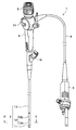
 図1に示すように、内視鏡1は、例えば、被検体内に挿入される長尺な挿入部2と、挿入部2の基端に設けられた操作部3と、操作部3の側部から延出されたユニバーサルコード4と、操作部3の基端に設けられた接眼部5と、ユニバーサルコード4の延出端に設けられたコネクタ6と、を備えて要部が構成された、所謂ファイバスコープである。なお、この内視鏡1は、コネクタ6を介して、光源装置等の外部装置(図示せず)に対して接続可能となっている。ここで、本実施形態においては、内視鏡1の構成について、ファイバスコープの構成を例に説明するが、本発明が適用される内視鏡1は、ファーバスコープに限定されないことは勿論である。 As shown in FIG. 1, an endoscope 1 includes, for example, a long insertion portion 2 to be inserted into a subject, an operation portion 3 provided at the proximal end of the insertion portion 2, and the operation portion 3 side. The main part is configured to include a universal cord 4 extending from the portion, an eyepiece portion 5 provided at the base end of the operation portion 3, and a connector 6 provided at the extension end of the universal cord 4. It is a so-called fiberscope. The endoscope 1 can be connected to an external device (not shown) such as a light source device via a connector 6. Here, in the present embodiment, the configuration of the endoscope 1 will be described by taking the configuration of a fiberscope as an example. However, the endoscope 1 to which the present invention is applied is not limited to a fiber scope. .
 挿入部2は、先端側に位置する先端硬質部11と、先端硬質部11の基端に連設された湾曲部12と、湾曲部12の基端に連設された可撓性を有する可撓管部13と、を有して要部が構成されている。 The insertion portion 2 has a distal end hard portion 11 located on the distal end side, a bending portion 12 provided continuously with the proximal end of the distal end hard portion 11, and a flexibility provided continuously with the proximal end of the bending portion 12. The main part is comprised including the flexible tube part 13.
 なお、先端硬質部11内には、図示しない観察用レンズや、照明用レンズ等が設けられている。 Note that an observation lens, an illumination lens, and the like (not shown) are provided in the distal end hard portion 11.
 また、湾曲部12は、操作部3に設けられた湾曲レバー14が回動操作されることにより、例えば、上下の2方向に湾曲自在となっている。 Further, the bending portion 12 can be bent in two directions, for example, up and down, when the bending lever 14 provided in the operation portion 3 is rotated.
 また、操作部3には、処置具挿入口15が設けられている。この処置具挿入口15は、挿入部2内に挿通された処置具挿通用チャンネル16(図5参照)の基端側に連通されている。これにより、処置具挿入口15に挿入された処置具は、処置具挿通用チャンネル16を介して挿入部2の先端側へと導かれ、先端硬質部11の先端面に形成された開口から、被検体内へと突出することが可能となっている。 Further, the operation unit 3 is provided with a treatment instrument insertion port 15. The treatment instrument insertion port 15 communicates with the proximal end side of a treatment instrument insertion channel 16 (see FIG. 5) inserted into the insertion portion 2. Thereby, the treatment instrument inserted into the treatment instrument insertion port 15 is guided to the distal end side of the insertion portion 2 via the treatment instrument insertion channel 16, and from the opening formed on the distal end surface of the distal end rigid portion 11, It is possible to project into the subject.
 ここで、挿入部2、及び、操作部3内には、処置具挿通用チャンネル16の他、上述した照明用レンズに照明光を伝達するライトガイド17や、上述した観察用レンズに集光された被検体内の光学像を接眼部5へと伝達するイメージガイド18や、湾曲レバー14の回動操作に連動して湾曲部12を湾曲動作させるためのアングルワイヤ19a,19b等(図5参照)が挿通されている。なお、ライトガイド17は、ユニバーサルコード4、及び、コネクタ6内にも挿通されている。 Here, in the insertion section 2 and the operation section 3, in addition to the treatment instrument insertion channel 16, the light guide 17 for transmitting the illumination light to the illumination lens described above and the observation lens described above are condensed. An image guide 18 that transmits an optical image in the subject to the eyepiece 5, angle wires 19a and 19b for bending the bending portion 12 in conjunction with the turning operation of the bending lever 14, etc. (FIG. 5). See) is inserted. The light guide 17 is also inserted into the universal cord 4 and the connector 6.
 次に、湾曲部12の構成について、詳細に説明する。なお、本実施形態において、湾曲部12は、先端側に位置する第1湾曲部12aと、当該第1湾曲部12aの基端に連設する第2湾曲部12bとを有して構成されている。これら第1,第2湾曲部12a,12bは、例えば、湾曲時の最小曲率半径が異なるものであり、第1湾曲部12aの最小曲率半径が、第2湾曲部12bの最小曲率半径よりも小さく設定されている。なお、湾曲部12としては、上述のように湾曲時の最小曲率半径が先端側と基端側とで2段階に異なる構成のものに限定されるものではなく、例えば、先端側から基端側までの最小曲率半径が均一な構成であってもよいことは勿論である。 Next, the configuration of the bending portion 12 will be described in detail. In the present embodiment, the bending portion 12 is configured to include a first bending portion 12a located on the distal end side and a second bending portion 12b provided continuously with the proximal end of the first bending portion 12a. Yes. For example, the first and second curved portions 12a and 12b have different minimum radii of curvature during bending, and the minimum radius of curvature of the first curved portion 12a is smaller than the minimum radius of curvature of the second curved portion 12b. Is set. As described above, the bending portion 12 is not limited to one having a configuration in which the minimum radius of curvature at the time of bending is different in two steps on the distal end side and the proximal end side, for example, from the distal end side to the proximal end side. Of course, the structure may have a uniform minimum radius of curvature.
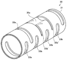
 図2乃至図5に示すように、湾曲部12は、例えば、超弾性合金材からなる円筒状の湾曲管本体31を主体とする湾曲管30と、この湾曲管30の周囲を覆う樹脂製の外皮32と、を備えて構成されている。ここで、湾曲管本体31を構成する超弾性合金材としては、例えば、Ni-Ti(ニッケルチタン)や、チタン合金、βチタン、純チタン、64チタン、A7075等が挙げられるが、これらに限定されるものではない。 As shown in FIGS. 2 to 5, the bending portion 12 is made of, for example, a bending tube 30 mainly composed of a cylindrical bending tube main body 31 made of a superelastic alloy material, and a resin-made covering the periphery of the bending tube 30. And an outer skin 32. Here, examples of the superelastic alloy material constituting the bending tube main body 31 include Ni—Ti (nickel titanium), titanium alloy, β titanium, pure titanium, 64 titanium, A7075, and the like. Is not to be done.
 湾曲管本体31には、当該湾曲管本体31の周方向に延在する部分円弧状の長孔からなる複数の湾曲用スロットが、例えばレーザ加工等により設けられている。 The bending tube main body 31 is provided with a plurality of bending slots formed by, for example, laser processing or the like, which are partially arc-shaped elongated holes extending in the circumferential direction of the bending tube main body 31.
 例えば、湾曲部12が上下(UP/DOWN)の2方向に湾曲自在な本実施形態において、具体的に説明すると、湾曲管本体31には、当該湾曲管本体31の湾曲方向上側から下側に延在する複数の湾曲用スロット33aと、湾曲管本体31の湾曲方向下側から上側に延在する複数の湾曲用スロット33bと、が設けられている。ここで、各湾曲用スロット33a,33bは、長手軸Oに対して互いに軸対称な形状をなす部分円弧状の長孔によってそれぞれ構成されている。 For example, in the present embodiment in which the bending portion 12 can be bent in two directions (UP / DOWN), specifically, the bending tube main body 31 includes the bending tube main body 31 from the upper side to the lower side in the bending direction. A plurality of bending slots 33a extending and a plurality of bending slots 33b extending upward from the lower side in the bending direction of the bending tube main body 31 are provided. Here, each of the bending slots 33a and 33b is constituted by a partial arc-shaped long hole having an axially symmetric shape with respect to the longitudinal axis O.
 図2に示すように、各湾曲用スロット33aは、第1湾曲部12aに対応して湾曲管本体31上に設定された第1の領域A1において、予め設定されたピッチP1毎に一列に配置され、さらに、第2湾曲部12bに対応して湾曲管本体31上に設定された第2の領域A2において、予め設定されたピッチP2(但し、P1<P2)毎に一列に配置されている。 As shown in FIG. 2, the bending slots 33a are arranged in a row for each preset pitch P1 in the first area A1 set on the bending tube body 31 corresponding to the first bending portion 12a. Further, in the second region A2 set on the bending tube main body 31 corresponding to the second bending portion 12b, they are arranged in a line for each preset pitch P2 (where P1 <P2). .
 同様に、各湾曲用スロット33bは、湾曲管本体31上に設定された第1の領域A1において、ピッチP1毎に一列に配置され、さらに、湾曲管本体31上に設定された第2の領域A2において、ピッチP2毎に一列に配置されている。 Similarly, the respective bending slots 33b are arranged in a line for each pitch P1 in the first region A1 set on the bending tube main body 31, and further, the second region set on the bending tube main body 31. In A2, they are arranged in a line for every pitch P2.
 ここで、第1の領域A1において、湾曲用スロット33bは、湾曲用スロット33aに対し、湾曲管本体31の長手軸O方向に半ピッチ(P1/2)ずつオフセットした状態で配置されている。同様に、第2の領域A2において、湾曲用スロット33bは、湾曲用スロット33aに対し、湾曲管本体31の長手軸O方向に半ピッチ(P2/2)ずつオフセットした状態で配置されている。そして、このように長手軸O方向にオフセットされることにより、各湾曲用スロット33aと各湾曲用スロット33bは、互いに干渉することなく、湾曲管本体31上に配置される。 Here, in the first region A1, the bending slot 33b is arranged offset from the bending slot 33a by a half pitch (P1 / 2) in the longitudinal axis O direction of the bending tube main body 31. Similarly, in the second region A2, the bending slot 33b is disposed in a state offset from the bending slot 33a by a half pitch (P2 / 2) in the longitudinal axis O direction of the bending tube main body 31. Then, by being offset in the direction of the longitudinal axis O in this way, each bending slot 33a and each bending slot 33b are arranged on the bending tube main body 31 without interfering with each other.
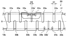
 ところで、本実施形態の湾曲管本体31上において、互いに隣接して対をなす特定の湾曲用スロット33aは、ワイヤガイド形成用スロットとして兼用されている(なお、以下において、これら特定の湾曲用スロット33aについては、他の湾曲用スロット33aと区別するため、符号に「’」を付して説明する)。そして、これら対をなす特定の湾曲用スロット33a’間において、湾曲管本体31のUP側の外周部の一部は内径方向に変形され、この変形によって、湾曲管30には、アングルワイヤ19aの中途が挿通されるワイヤガイド35aが形成されている(例えば、図3,4参照)。 By the way, on the bending tube main body 31 of the present embodiment, the specific bending slots 33a paired adjacent to each other are also used as wire guide forming slots (hereinafter, these specific bending slots will be described below). 33a will be described with a symbol “′” in order to distinguish it from other bending slots 33a). Then, between the specific bending slots 33a ′ that make a pair, a part of the outer peripheral portion on the UP side of the bending tube main body 31 is deformed in the inner diameter direction, and this deformation causes the bending tube 30 to have the angle wire 19a. A wire guide 35a that is inserted in the middle is formed (for example, see FIGS. 3 and 4).
 同様に、本実施形態の湾曲管本体31上において、互いに隣接して対をなす特定の湾曲用スロット33bは、ワイヤガイド成形用スロットとして兼用されている(なお、以下において、これら特定の湾曲用スロット33bについては、他の湾曲用スロット33bと区別するため、符号に「’」を付して説明する。)そして、対をなす特定の湾曲用スロット33b’間において、湾曲管本体31のDOWN側の外周部の一部は内径方向に変形され、この変形によって、湾曲管30には、アングルワイヤ19bの中途が挿通されるワイヤガイド35bが形成されている。 Similarly, on the bending tube main body 31 of the present embodiment, the specific bending slots 33b that are paired adjacent to each other are also used as wire guide forming slots (hereinafter, these specific bending slots are used). The slot 33b will be described with a symbol “′” attached to it in order to distinguish it from the other bending slots 33b.) And between the specific bending slots 33b ′ that make a pair, the DOWN of the bending tube main body 31 will be described. A part of the outer peripheral portion on the side is deformed in the inner diameter direction, and by this deformation, a wire guide 35b through which the middle of the angle wire 19b is inserted is formed in the bending tube 30.
 なお、各ワイヤガイド35a,35bは、例えば、湾曲管本体31を所定の加工治具に位置決めしてセットし、湾曲管本体31上の該当部位(対をなす湾曲用スロット33a’間、及び、対をなす湾曲用スロット33b’間)を加工治具によって内径方向にプレスした状態で、高温の塩中に所定時間浸漬させる等の熱処理を行うことにより、形成される。 Each of the wire guides 35a and 35b is set, for example, by positioning the bending tube main body 31 on a predetermined processing jig, and corresponding portions on the bending tube main body 31 (between a pair of bending slots 33a ′ and It is formed by performing a heat treatment such as immersing in a high-temperature salt for a predetermined time in a state in which a pair of bending slots 33b ′) is pressed in the inner diameter direction by a processing jig.
 このような構成において、湾曲管30のUP側への湾曲時の最小曲率半径Rは、主として湾曲用スロット33a(及び、33a’)に依拠し、湾曲部30のDOWN側への湾曲時の最小曲率半径Rは、主として湾曲用スロット33b(及び、33b’)に依拠して規定される。 In such a configuration, the minimum radius of curvature R when the bending tube 30 is bent toward the UP side mainly depends on the bending slot 33a (and 33a ′), and the minimum radius when the bending portion 30 is bent toward the DOWN side. The radius of curvature R is defined mainly depending on the bending slot 33b (and 33b ′).
 すなわち、例えば、湾曲管30の第1の領域A1がUP側に湾曲されるに際し、湾曲管本体31の湾曲用スロット33a(33a’)における屈曲は、当該湾曲用スロット33a(33a’)を形成する前後の壁部が当接することにより所定に制限される。換言すれば、湾曲管本体31の湾曲用スロット33a(33a’)におけるピッチP1毎の最大屈曲角度αは、基本的には、湾曲用スロット33a(33a’)の幅によって規定される。 That is, for example, when the first region A1 of the bending tube 30 is bent to the UP side, the bending in the bending slot 33a (33a ′) of the bending tube body 31 forms the bending slot 33a (33a ′). When the front and rear wall portions come into contact with each other, it is limited to a predetermined value. In other words, the maximum bending angle α for each pitch P1 in the bending slot 33a (33a ′) of the bending tube body 31 is basically defined by the width of the bending slot 33a (33a ′).
 但し、湾曲管本体31にワイヤガイド35aを一体形成した本実施形態においては、ワイヤガイド形成用スロットを兼用する特定の湾曲用スロット33a’を形成する前後の壁部が段違いとなっている。従って、特定の湾曲用スロット33a’の幅が他の湾曲用スロット33aの幅と同一の幅である場合、特定の湾曲用スロット33a’の前後の壁部が当接するタイミングは、他の湾曲用スロット33aの前後の壁部が当接するタイミングよりも遅くなる。換言すれば、幅が同一である場合、例えば、図7に示すように、特定の湾曲用スロット33a’における折曲角度α2が他の湾曲用スロット33aにおける折曲角度α1よりも大きくなり、結果として、特定の湾曲用スロット33a’の前後所定区間における最小曲率半径R2は、他の湾曲用スロット33aの前後所定区間における最小曲率半径R1よりも相対的に小さくなる。 However, in this embodiment in which the wire guide 35a is formed integrally with the bending tube main body 31, the wall portions before and after forming the specific bending slot 33a 'that also serves as the wire guide forming slot are stepped. Accordingly, when the width of the specific bending slot 33a ′ is the same as the width of the other bending slot 33a, the timing at which the front and rear wall portions of the specific bending slot 33a ′ come into contact with each other is It is later than the timing at which the front and rear wall portions of the slot 33a abut. In other words, when the widths are the same, for example, as shown in FIG. 7, the bending angle α2 in the specific bending slot 33a ′ becomes larger than the bending angle α1 in the other bending slots 33a, and the result As described above, the minimum curvature radius R2 in the predetermined section before and after the specific bending slot 33a ′ is relatively smaller than the minimum curvature radius R1 in the predetermined section before and after the other bending slot 33a.
 これに対し、本実施形態においては、例えば、図2に示すように、特定の湾曲用スロット33a’における折曲角度α2を他の湾曲用スロット33aにおける折曲角度α1と一致させるべく、特定の湾曲用スロット33a’の幅H2が、他の湾曲用スロット33aの幅H1よりも相対的に狭くなるよう調整されている。これにより、特定の湾曲用スロット33a’の前後所定区間における最小曲率半径R2は、他の湾曲用スロット33aの前後所定区間における最小曲率半径R1と等しくなり、第1湾曲部12aは均一な円弧状に湾曲される。 On the other hand, in the present embodiment, as shown in FIG. 2, for example, a specific bending angle α2 in a specific bending slot 33a ′ is specified to match a bending angle α1 in another bending slot 33a. The width H2 of the bending slot 33a ′ is adjusted to be relatively narrower than the width H1 of the other bending slots 33a. Thereby, the minimum curvature radius R2 in the predetermined section before and after the specific bending slot 33a ′ is equal to the minimum curvature radius R1 in the predetermined section before and after the other bending slot 33a, and the first bending portion 12a has a uniform arc shape. To be curved.
 なお、具体的な説明は省略するが、図2に示すように、第2の領域A2における特定の湾曲用スロット33a’の幅H2、第1,第2の領域A1,A2における特定の湾曲用スロット33b’の幅H2についても同様の調整が行われていることは勿論である。 Although not described in detail, as shown in FIG. 2, the width H2 of the specific bending slot 33a ′ in the second area A2 and the specific bending in the first and second areas A1 and A2. Of course, the same adjustment is made for the width H2 of the slot 33b '.
 このような実施形態によれば、円筒状の湾曲管本体31の長手軸O方向に沿って設定間隔毎に設けられ当該湾曲管本体31の周方向に延在する複数の湾曲用スロット33a(及び、湾曲用スロット33b)と、複数の湾曲用スロット33a(及び、湾曲用スロット33b)の配列上に対をなして設けられた湾曲管本体31の周方向に延在するワイヤガイド形成用スロット(湾曲用スロット33a’(及び、湾曲用スロット33b’))と、対をなすワイヤガイド形成用スロット間において湾曲管本体31の外周部を内径方向に変形させて形成したワイヤガイド35a,35bと、を具備する湾曲管30において、ワイヤガイド35a,35bに近接する湾曲用スロット33a’,33b’の幅H2を、他の湾曲用スロット33a,33bの幅H1よりも相対的に狭く設定したことにより、簡単な構成により、湾曲部12(湾曲管30)を所望の湾曲形状に湾曲動作させることができる。すなわち、ワイヤガイド35a,35bを湾曲管本体31に一体形成して構造を簡素化した場合においても、ワイヤガイド35a,35bに近接する湾曲用スロット(特定の湾曲用スロット33a’33b’)の幅H2を他の湾曲用スロット33a,33bの幅H1よりも相対的に狭く設定することにより、湾曲部12の各部(第1湾曲部12a及び第2湾曲部12b)をそれぞれ均一に湾曲動作させることができる。 According to such an embodiment, the plurality of bending slots 33a (and so on) that are provided at set intervals along the longitudinal axis O direction of the cylindrical bending tube body 31 and extend in the circumferential direction of the bending tube body 31. , A bending slot 33b) and a wire guide forming slot extending in the circumferential direction of the bending tube main body 31 provided in a pair on the arrangement of the bending slots 33a (and the bending slots 33b). Wire guides 35a and 35b formed by deforming the outer peripheral portion of the bending tube body 31 in the inner diameter direction between the pair of wire guide forming slots and the bending slot 33a ′ (and the bending slot 33b ′); In the bending tube 30 having the width H2 of the bending slots 33a ′ and 33b ′ adjacent to the wire guides 35a and 35b, the width H2 of the other bending slots 33a and 33b. By set relatively smaller than H1, with a simple configuration, the bending portion 12 (the bending tube 30) can be bent operate in a desired curved shape. That is, even when the wire guides 35a and 35b are formed integrally with the bending tube main body 31 to simplify the structure, the width of the bending slot (specific bending slot 33a'33b ') adjacent to the wire guides 35a and 35b. By setting H2 to be relatively narrower than the width H1 of the other bending slots 33a and 33b, each portion of the bending portion 12 (the first bending portion 12a and the second bending portion 12b) is uniformly bent. Can do.
 この場合において、複数の湾曲用スロット33a,33bのうち、特定の湾曲用スロット33a’,33b’をワイヤガイド形成用スロットとして兼用することにより、スロット数を増加させることなくワイヤガイド35a,35bを一体形成することができ、湾曲管30の構成をより簡素化することができる。 In this case, among the plurality of bending slots 33a and 33b, the specific bending slots 33a ′ and 33b ′ are also used as the wire guide forming slots, so that the wire guides 35a and 35b can be formed without increasing the number of slots. It can form integrally, and the structure of the bending tube 30 can be simplified more.
 次に、図8,9は本発明の第2の実施形態に係わり、図8は湾曲管の要部を一部破断して示す側面図、図9は湾曲管の要部を示す斜視図である。なお、本実施形態は、ワイヤガイド形成用スロットを湾曲用スロット33a,33bとは別に設けた点が上述の第1の実施形態に対して主として異なる。その他、上述の第1の実施形態と同様の構成については、同符号を付して説明を省略する。また、湾曲管30におけるUP側の構成とDOWN側の構成とは略同様の構成であるため、本実施形態においては、主としてUP側の構成について説明し、DOWN側の構成の説明については適宜省略する。 Next, FIGS. 8 and 9 relate to the second embodiment of the present invention, FIG. 8 is a side view showing a part of the bending tube in a partially broken state, and FIG. 9 is a perspective view showing the part of the bending tube. is there. This embodiment is mainly different from the first embodiment described above in that the wire guide forming slot is provided separately from the bending slots 33a and 33b. In addition, about the structure similar to the above-mentioned 1st Embodiment, a same sign is attached | subjected and description is abbreviate | omitted. In addition, since the UP-side configuration and the DOWN-side configuration of the bending tube 30 are substantially the same configuration, in this embodiment, the UP-side configuration will be mainly described, and the description of the DOWN-side configuration will be omitted as appropriate. To do.
 図8,9に示すように、本実施形態の湾曲管本体31上において、複数の湾曲用スロット33aのうち、対をなす特定の湾曲用スロット33a’間には、対をなすワイヤガイド形成用スロット34aが設けられている。 As shown in FIGS. 8 and 9, on the bending tube main body 31 of the present embodiment, a pair of specific bending slots 33a ′ among a plurality of bending slots 33a is used to form a pair of wire guides. A slot 34a is provided.
 そして、対をなすワイヤガイド形成用スロット34a間において、湾曲管本体31の外周部の一部が内径方向に変形され、この変形によって、湾曲管30には、アングルワイヤ19aの中途が挿通されるワイヤガイド35aが形成されている。 A part of the outer peripheral portion of the bending tube main body 31 is deformed in the inner diameter direction between the pair of wire guide forming slots 34a, and the middle of the angle wire 19a is inserted into the bending tube 30 by this deformation. A wire guide 35a is formed.
 ところで、上述のようにワイヤガイド形成用スロット34a,34bを別途設けた本実施形態の構成では、当該ワイヤガイド形成用スロット34a,34bを設けた部位における湾曲管本体31の剛性が、超弾性合金であるが由に、部分的に低下する。そして、このような剛性の部分的な低下は、湾曲管30の湾曲特性にも影響を及ぼす。 By the way, in the configuration of the present embodiment in which the wire guide forming slots 34a and 34b are separately provided as described above, the rigidity of the bending tube body 31 in the portion where the wire guide forming slots 34a and 34b are provided is superelastic alloy. However, it is partially reduced. Such a partial reduction in rigidity also affects the bending characteristics of the bending tube 30.
 そこで、本実施形態においては、ワイヤガイド形成用スロット34a,34bに近接する特定の湾曲用スロット33a’,33b’の幅H3が、他の湾曲用スロット33a,33bの幅H1よりも相対的に狭く設定され、この幅H3の調整によって、湾曲管30の湾曲特性の均斉化が図られている。 Therefore, in this embodiment, the width H3 of the specific bending slots 33a ′ and 33b ′ adjacent to the wire guide forming slots 34a and 34b is relatively larger than the width H1 of the other bending slots 33a and 33b. It is set narrowly, and the bending characteristics of the bending tube 30 are made uniform by adjusting the width H3.
 この場合において、ワイヤガイド形成用スロット34a,34bの幅H4は幅H1,H3に対し狭く設定されていることが望ましい。さらに、ワイヤガイド形成用スロット34a,34bの延在長さについても、ワイヤガイド35a,35bの形成に支障を来たさない範囲において、湾曲用スロット33a,33bよりも可能な限り短く設定されていることが望ましい。 In this case, it is desirable that the width H4 of the wire guide forming slots 34a and 34b is set narrower than the widths H1 and H3. Further, the extending lengths of the wire guide forming slots 34a and 34b are set to be as short as possible as compared with the bending slots 33a and 33b within a range that does not hinder the formation of the wire guides 35a and 35b. It is desirable.
 このような実施形態によれば、上述の第1の実施形態で得られる作用効果に加え、特定の湾曲用スロット33a’,33b’の前後の壁部に段差が生じないため、幅H1に対し、幅H3を大幅に変更することなく、湾曲管30の湾曲特性を均斉化することができるという効果を奏する。 According to such an embodiment, in addition to the operational effects obtained in the first embodiment described above, there is no step in the front and rear wall portions of the specific bending slots 33a ′ and 33b ′. There is an effect that the bending characteristics of the bending tube 30 can be uniformed without significantly changing the width H3.
 次に、図10,11は本発明の第3の実施形態に係わり、図10は湾曲管の要部を一部破断して示す側面図、図11は湾曲管の要部を示す斜視図である。なお、本実施形態は、ワイヤガイド形成用スロットを湾曲用スロット33a,33bとは別に設けた点が上述の第1の実施形態に対して主として異なる。その他、上述の第1の実施形態と同様の構成については、同符号を付して説明を省略する。また、湾曲管30におけるUP側の構成とDOWN側の構成とは略同様の構成であるため、本実施形態においては、主としてUP側の構成について説明し、DOWN側の構成の説明については適宜省略する。 Next, FIGS. 10 and 11 relate to a third embodiment of the present invention, FIG. 10 is a side view showing a part of the bending tube in a partially broken view, and FIG. 11 is a perspective view showing the part of the bending tube. is there. This embodiment is mainly different from the first embodiment described above in that the wire guide forming slot is provided separately from the bending slots 33a and 33b. In addition, about the structure similar to the above-mentioned 1st Embodiment, a same sign is attached | subjected and description is abbreviate | omitted. In addition, since the UP-side configuration and the DOWN-side configuration of the bending tube 30 are substantially the same configuration, in this embodiment, the UP-side configuration will be mainly described, and the description of the DOWN-side configuration will be omitted as appropriate. To do.
 図10,11に示すように、本実施形態の湾曲管本体31上において、複数の湾曲用スロット33aのうち、特定の湾曲用スロット33a’を挟む位置には、対をなすワイヤガイド形成用スロット34aが設けられている。 As shown in FIGS. 10 and 11, on the bending tube main body 31 of the present embodiment, a pair of wire guide forming slots is formed at a position sandwiching a specific bending slot 33a ′ among the plurality of bending slots 33a. 34a is provided.
 そして、対をなすワイヤガイド形成用スロット34a間において、湾曲管本体31の外周部の一部が内径方向に変形され、この変形によって、湾曲管30には、アングルワイヤ19aの中途が挿通されるワイヤガイド35aが形成されている。 A part of the outer peripheral portion of the bending tube main body 31 is deformed in the inner diameter direction between the pair of wire guide forming slots 34a, and the middle of the angle wire 19a is inserted into the bending tube 30 by this deformation. A wire guide 35a is formed.
 ところで、上述のようにワイヤガイド形成用スロット34a,34bを別途設けた本実施形態では、当該ワイヤガイド形成用スロット34a,34bを設けた部位における湾曲管本体31の剛性が、超弾性合金であるが由に、部分的に低下する。そして、このような剛性の部分的な低下は、湾曲管30の湾曲特性にも影響を及ぼす。 By the way, in the present embodiment in which the wire guide forming slots 34a and 34b are separately provided as described above, the rigidity of the bending tube body 31 in the portion where the wire guide forming slots 34a and 34b are provided is a superelastic alloy. Because of this, it is partially reduced. Such a partial reduction in rigidity also affects the bending characteristics of the bending tube 30.
 また、ワイヤガイド35a,35bの形成により、特定の湾曲用スロット33a’,33b’の前後の側壁の当接位置は、他の湾曲用スロット33a,33bの前後の側壁の当接位置よりも低くなっている。従って、特定の湾曲用スロット33a’,33b’の幅H5を、他の湾曲用スロット33a,33bの幅H1と同程度に設定した場合、特定の湾曲用スロット33a’,33b’の前後の壁部が当接するタイミングは、他の湾曲用スロット33a,33bの前後の壁部が当接するタイミングよりも遅くなる。 Further, due to the formation of the wire guides 35a and 35b, the contact positions of the front and rear side walls of the specific bending slots 33a ′ and 33b ′ are lower than the contact positions of the front and rear side walls of the other bending slots 33a and 33b. It has become. Therefore, when the width H5 of the specific bending slots 33a ′ and 33b ′ is set to be approximately the same as the width H1 of the other bending slots 33a and 33b, the walls before and after the specific bending slots 33a ′ and 33b ′ The timing at which the portions abut is later than the timing at which the front and back wall portions of the other bending slots 33a and 33b abut.
 そこで、本実施形態においては、ワイヤガイド形成用スロット34a,34bに近接する特定の湾曲用スロット33a’,33b’の幅H5が、他の湾曲用スロット33a,33bの幅H1よりも相対的に狭く設定され、この幅H5の調整によって、湾曲管30の湾曲特性の均斉化が図られている。 Therefore, in this embodiment, the width H5 of the specific bending slots 33a ′ and 33b ′ adjacent to the wire guide forming slots 34a and 34b is relatively larger than the width H1 of the other bending slots 33a and 33b. The bending characteristics of the bending tube 30 are made uniform by adjusting the width H5.
 このような実施形態によれば、上述の第1の実施形態で得られる作用効果に加え、別途の幅調整を要する特定の湾曲用スロット33a’,33b’の数を減少させることができるという効果を奏する。 According to such an embodiment, in addition to the operational effects obtained in the first embodiment described above, the number of specific bending slots 33a ′ and 33b ′ that require separate width adjustment can be reduced. Play.
 次に、図12,13は本発明の第4の実施形態に係わり、図12は湾曲管の要部を一部切断して示す側面図、図13は湾曲管の要部を示す斜視図である。なお、本実施形態は、対をなすワイヤガイド形成用スロットのうちの一方を湾曲用スロット33a,33bで兼用し、他方を別途に設けた点が上述の第1の実施形態に対して主として異なる。その他、上述の第1の実施形態と同様の構成については、同符号を付して説明を省略する。また、湾曲管30におけるUP側の構成とDOWN側の構成とは略同様の構成であるため、本実施形態においては、主としてUP側の構成について説明し、DOWN側の構成の説明については適宜省略する。 Next, FIGS. 12 and 13 relate to a fourth embodiment of the present invention, FIG. 12 is a side view showing a cutaway part of the main part of the bending tube, and FIG. 13 is a perspective view showing the main part of the bending pipe. is there. This embodiment is mainly different from the first embodiment described above in that one of the paired wire guide forming slots is also used as the bending slots 33a and 33b and the other is provided separately. . In addition, about the structure similar to the above-mentioned 1st Embodiment, a same sign is attached | subjected and description is abbreviate | omitted. In addition, since the UP-side configuration and the DOWN-side configuration of the bending tube 30 are substantially the same configuration, in this embodiment, the UP-side configuration will be mainly described, and the description of the DOWN-side configuration will be omitted as appropriate. To do.
 図12,13に示すように、本実施形態の湾曲管本体31上において、複数の湾曲用スロット33aのうち、特定の湾曲用スロット33a’が、対をなすワイヤガイド形成用スロットの一方として兼用されている。また、湾曲管本体31上において、特定の湾曲用スロット33a’に隣接する位置には他方のワイヤガイド形成用スロット34a(或いは、ワイヤガイド形成用スロット34b)が設けられている。 As shown in FIGS. 12 and 13, on the bending tube main body 31 of the present embodiment, among the plurality of bending slots 33a, a specific bending slot 33a ′ is also used as one of a pair of wire guide forming slots. Has been. On the bending tube main body 31, the other wire guide forming slot 34a (or the wire guide forming slot 34b) is provided at a position adjacent to the specific bending slot 33a '.
 そして、これら特定の湾曲用スロット33a’とワイヤガイド形成用スロット34aとの間において、湾曲管本体31の外周部の一部が内径方向に変形され、この変形によって、湾曲管30には、アングルワイヤ19aの中途が挿通されるワイヤガイド35aが形成されている。 A part of the outer peripheral portion of the bending tube main body 31 is deformed in the inner diameter direction between the specific bending slot 33a ′ and the wire guide forming slot 34a. A wire guide 35a through which the middle of the wire 19a is inserted is formed.
 ところで、特定の湾曲用スロット33a’,33b’では、前後の壁部が段違いとなっている。従って、特定の湾曲用スロット33a’,33b’の幅H6を、他の湾曲用スロット33a,33bの幅H1と同程度に設定した場合、特定の湾曲用スロット33a’,33b’の前後の壁部が当接するタイミングは、他の湾曲用スロット33a,33bの前後の壁部が当接するタイミングよりも遅くなる。 By the way, in the specific bending slots 33a 'and 33b', the front and rear wall portions are stepped. Therefore, when the width H6 of the specific bending slots 33a ′ and 33b ′ is set to be approximately the same as the width H1 of the other bending slots 33a and 33b, the walls before and after the specific bending slots 33a ′ and 33b ′ The timing at which the portions abut is later than the timing at which the front and back wall portions of the other bending slots 33a and 33b abut.
 また、上述のようにワイヤガイド形成用スロット34a,34bを別途設けた本実施形態では、当該ワイヤガイド形成用スロット34a,34bを設けた部位における湾曲管本体31の剛性が、部分的に低下する。そして、このような剛性の部分的な低下は、湾曲管30の湾曲特性にも影響を及ぼす。 Further, in the present embodiment in which the wire guide forming slots 34a and 34b are separately provided as described above, the rigidity of the bending tube main body 31 at the portion where the wire guide forming slots 34a and 34b are provided is partially reduced. . Such a partial reduction in rigidity also affects the bending characteristics of the bending tube 30.
 そこで、本実施形態においては、ワイヤガイド形成用スロット34a,34bに近接する特定の湾曲用スロット33a’,33b’の幅H6が、他の湾曲用スロット33a,33bの幅H1よりも相対的に狭く設定され、この幅H6の調整によって、湾曲管30の湾曲特性の均斉化が図られている。 Therefore, in this embodiment, the width H6 of the specific bending slots 33a ′ and 33b ′ adjacent to the wire guide forming slots 34a and 34b is relatively larger than the width H1 of the other bending slots 33a and 33b. The bending characteristic of the bending tube 30 is made uniform by adjusting the width H6.
 このような実施形態によれば、上述の第1の実施形態で得られる作用効果に加え、別途の幅調整を要する特定の湾曲用スロット33a’,33b’の数を減少させることができるという効果を奏する。 According to such an embodiment, in addition to the operational effects obtained in the first embodiment described above, the number of specific bending slots 33a ′ and 33b ′ that require separate width adjustment can be reduced. Play.
 次に,図14,15は本発明の第5の実施形態に係わり、図14は湾曲管の要部を一部破断して示す側面図、図15は湾曲管の要部を示す斜視図である。なお、本実施形態は、特定の湾曲用スロット33a’,33b’の端部に歪緩和用の貫通孔36a,36bを設けた点が上述の第1の実施形態に対して主として異なる。その他、上述の第1の実施形態と同様の構成については、同符号を付して説明を省略する。また、湾曲管30におけるUP側の構成とDOWN側の構成とは略同様の構成であるため、本実施形態においては、主としてUP側の構成について説明し、DOWN側の構成の説明については適宜省略する。 Next, FIGS. 14 and 15 relate to a fifth embodiment of the present invention. FIG. 14 is a side view showing a part of the bending tube in a partially broken view. FIG. 15 is a perspective view showing the part of the bending tube. is there. This embodiment is mainly different from the first embodiment described above in that strain relief through holes 36a and 36b are provided at end portions of the specific bending slots 33a 'and 33b'. In addition, about the structure similar to the above-mentioned 1st Embodiment, a same sign is attached | subjected and description is abbreviate | omitted. In addition, since the UP-side configuration and the DOWN-side configuration of the bending tube 30 are substantially the same configuration, in this embodiment, the UP-side configuration will be mainly described, and the description of the DOWN-side configuration will be omitted as appropriate. To do.
 図14,15に示すように、本実施形態の湾曲管本体31上において、特定の湾曲用スロット33a’,33b’の端部には、例えば、丸孔からなる歪緩和用の貫通孔36a,36bが設けられている。これら歪緩和用の貫通孔36a,36bの直径は、特定の湾曲用スロット33a’,33b’の幅H2よりも相対的に大きく設定されている。より具体的には、本実施形態において、歪緩和用の貫通孔36a,36bの直径は、他の湾曲用スロット33a,33bの幅H1と等しくなるよう設定されている。 As shown in FIGS. 14 and 15, on the bending tube main body 31 of the present embodiment, the end portions of the specific bending slots 33 a ′ and 33 b ′ are, for example, strain-reducing through holes 36 a, which are round holes. 36b is provided. The diameters of the strain relief through holes 36a and 36b are set to be relatively larger than the width H2 of the specific bending slots 33a 'and 33b'. More specifically, in the present embodiment, the diameters of the strain relief through holes 36a and 36b are set to be equal to the width H1 of the other bending slots 33a and 33b.
 このような実施形態によれば、特定の湾曲用スロット33a’,33b’の端部に歪緩和用の貫通孔36a,36bを設けることにより、幅H2を相対的に狭く設定した特定の湾曲用スロット33a’,33b’においても、他の湾曲用スロット33a,33bと同等の耐久性を確保することができる。すなわち、幅H2を狭くした特定の湾曲用スロット33a’,33b’では、他の湾曲用スロット33a,33bに比べ、湾曲時の歪による応力がスロット端部に集中するが、歪緩和用の貫通孔36a,36bを設けることにより、この応力集中を緩和することができる。従って、均一な湾曲特性を確保しつつ、繰り返し湾曲動作等させた場合にも、金属疲労等に対する耐久性を他の湾曲用スロット33a,33bと同等に確保することができる。 According to such an embodiment, by providing the through holes 36a and 36b for strain relief at the end portions of the specific bending slots 33a ′ and 33b ′, the specific bending use with the width H2 set relatively narrow. Also in the slots 33a ′ and 33b ′, durability equivalent to that of the other bending slots 33a and 33b can be ensured. That is, in the specific bending slots 33a ′ and 33b ′ in which the width H2 is narrowed, the stress due to distortion at the time of bending is concentrated at the end of the slot as compared with the other bending slots 33a and 33b. By providing the holes 36a and 36b, this stress concentration can be relaxed. Accordingly, even when repeated bending operations are performed while ensuring uniform bending characteristics, durability against metal fatigue or the like can be ensured equivalent to the other bending slots 33a and 33b.
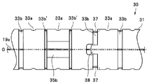
 次に、図16乃至図22は本発明の第6の実施形態に係わり、図16は湾曲管の要部を一部破断して示す側面図、図17は湾曲管の要部を示す斜視図、図18は第1変形例に係わり湾曲管の要部を一部破断して示す側面図、図19は第1変形例に係わり湾曲管の要部を示す斜視図、図20は第2変形例に係わり湾曲管の要部を示す上面図、図21は第2変形例に係わり湾曲管の要部を示す斜視図、図22は第3変形例に係わり湾曲管の要部を示す上面図である。なお、本実施形態は、主として、ワイヤガイド35a,35bを形成する際の作業性を向上するための構成について説明するものである。その他、上述の第1の実施形態と同様の構成については、同符号を付して説明を省略する。 Next, FIG. 16 to FIG. 22 relate to a sixth embodiment of the present invention, FIG. 16 is a side view showing a partially broken main portion of the bending tube, and FIG. 17 is a perspective view showing the main portion of the bending tube. FIG. 18 is a side view showing a partially broken main portion of the bending tube according to the first modification, FIG. 19 is a perspective view showing the main portion of the bending tube according to the first modification, and FIG. 20 is a second deformation. FIG. 21 is a perspective view showing the main part of the bending tube related to the second modification, and FIG. 22 is a top view showing the main part of the bending pipe related to the third modification. It is. In addition, this embodiment mainly demonstrates the structure for improving the workability | operativity at the time of forming wire guide 35a, 35b. In addition, about the structure similar to the above-mentioned 1st Embodiment, a same sign is attached | subjected and description is abbreviate | omitted.
 図16,17に示すように、本実施形態において、湾曲管本体31の側部には、一側から他側に貫通する位置決め用の貫通孔37が設けられている。この位置決め用の貫通孔37は、例えば、図示しない加工治具を用いてワイヤガイド35a,35bを形成する際に、当該加工治具に対して湾曲管本体31を位置決めするために用いられるものである。 As shown in FIGS. 16 and 17, in the present embodiment, a positioning through-hole 37 penetrating from one side to the other side is provided in the side portion of the bending tube main body 31. The positioning through-hole 37 is used, for example, to position the bending tube body 31 with respect to the processing jig when forming the wire guides 35a and 35b using a processing jig (not shown). is there.
 本実施形態において、位置決め用の貫通孔37は、例えば、湾曲用スロット33bの両端部にそれぞれ設けられている。 In the present embodiment, the positioning through-holes 37 are provided at both ends of the bending slot 33b, for example.
 そして、このような位置決め用の貫通孔37を湾曲管本体31上の適所に設けることにより、長尺な湾曲管本体31を加工治具に対して精度良く位置決めすることが可能となる。 Further, by providing such positioning through-holes 37 at appropriate positions on the bending tube main body 31, the long bending tube main body 31 can be accurately positioned with respect to the processing jig.
 ところで、このような位置決め用の貫通孔37は比較的大径の孔部で構成されるため、湾曲管本体31上において、位置決め用の貫通孔37の形成部位の剛性が部分的に低下する。そして、このように部分的に剛性が低下した場合、弾性変形量が部分的に大きくなり、当該部位の最小湾曲半径が、湾曲用スロット33aの幅H1によって規定された湾曲半径以下となる場合がある。 By the way, since the positioning through-hole 37 is composed of a relatively large-diameter hole, the rigidity of the portion where the positioning through-hole 37 is formed is partially lowered on the bending tube main body 31. When the rigidity is partially reduced in this way, the amount of elastic deformation is partially increased, and the minimum bending radius of the part may be less than or equal to the bending radius defined by the width H1 of the bending slot 33a. is there.
 そこで、本実施形態においては、例えば、図18,19に示すように、このような湾曲特性の不均一性を是正するため、位置決め用の貫通孔37に近接する湾曲用スロット33aの幅H7を他の湾曲用スロット33aの幅H1よりも相対的に狭く設定することが可能である。 Therefore, in this embodiment, for example, as shown in FIGS. 18 and 19, in order to correct such unevenness of the bending characteristics, the width H7 of the bending slot 33a adjacent to the positioning through-hole 37 is set. It can be set relatively narrower than the width H1 of the other bending slot 33a.
 また、このような位置決め用貫通孔37を設けた場合、湾曲管本体31の長手軸O周りの捩り剛性についても部分的に低下する。 Further, when such a positioning through hole 37 is provided, the torsional rigidity around the longitudinal axis O of the bending tube main body 31 is also partially reduced.
 そこで、本実施形態においては、例えば、図20,21に示すように、このような捩り剛性の低下を補うため、位置決め用の貫通孔37を有する湾曲用スロット33bの一部をクランク状に形成し、捩れ規制用のタブ38を設けることも可能である。 Therefore, in this embodiment, for example, as shown in FIGS. 20 and 21, a part of the bending slot 33b having the positioning through-hole 37 is formed in a crank shape in order to compensate for such a decrease in torsional rigidity. However, it is possible to provide a tab 38 for twist control.
 また、上述の説明においては、湾曲用スロット33bの両端部に位置決め用の貫通孔37をそれぞれ設けた一例について説明したが、加工治具に対する誤組を防止するため、例えば、図22に示すように、湾曲用スロット33bの一端部のみに設けることも可能である。 In the above description, an example in which the positioning through holes 37 are provided at both ends of the bending slot 33b has been described. However, in order to prevent erroneous assembly with respect to the processing jig, for example, as shown in FIG. In addition, it is possible to provide only at one end of the bending slot 33b.
 なお、本実施形態においては、湾曲用スロット33bの端部に位置決め用の貫通孔37を設けた一例について説明したが、逆に、湾曲用スロット33aの端部に位置決め用の貫通孔37を設けても良いことは勿論である。 In this embodiment, an example in which the positioning through-hole 37 is provided at the end of the bending slot 33b has been described. Conversely, the positioning through-hole 37 is provided at the end of the bending slot 33a. Of course, it may be.
 なお、本発明は、以上説明した各実施形態に限定されることなく、種々の変形や変更が可能であり、それらも本発明の技術的範囲内である。例えば、上述の第1の実施形態で示した構成と、上述の第3の実施形態で示した構成と、を組み合わせることが可能である。すなわち、例えば、図23,24に示すように、湾曲管本体31のUP側において、複数の湾曲用スロット33aのうち、特定の湾曲用スロット33a’を挟む位置に対をなすワイヤガイド形成用スロット34aを設けてワイヤガイド35aを形成し、一方、湾曲管本体31のDOWN側において、複数の湾曲用スロット33bのうち、対をなす特定の湾曲用スロット33b’をワイヤガイド形成用スロットとして兼用してワイヤガイド35bを形成することも可能である。このように構成すれば、湾曲管本体31の長手軸O方向においてUP側とDOWN側の同じ位置で、ワイヤガイド35a,35bをプレスできるため、プレス時に加工治具や湾曲管本体31を傾きづらくすることができる。その他、説明を省略するが、上述の各実施形態について、各種組み合わせ等が可能であることは勿論である。 The present invention is not limited to the embodiments described above, and various modifications and changes are possible, and these are also within the technical scope of the present invention. For example, it is possible to combine the configuration shown in the first embodiment and the configuration shown in the third embodiment. That is, for example, as shown in FIGS. 23 and 24, on the UP side of the bending tube main body 31, a wire guide forming slot that is paired with a position sandwiching a specific bending slot 33 a ′ among the plurality of bending slots 33 a. 34a is provided to form the wire guide 35a. On the other hand, on the DOWN side of the bending tube main body 31, a specific bending slot 33b 'that forms a pair among the plurality of bending slots 33b is also used as a wire guide forming slot. It is also possible to form the wire guide 35b. With this configuration, the wire guides 35a and 35b can be pressed at the same position on the UP side and the DOWN side in the longitudinal axis O direction of the bending tube main body 31, so that it is difficult to tilt the processing jig and the bending tube main body 31 during pressing. can do. In addition, although description is abbreviate | omitted, of course, various combinations etc. are possible about each above-mentioned embodiment.
 また、上述の各実施形態においては、上下の2方向に湾曲自在な湾曲管30の一例について説明したが、本発明はこれに限定されるものではなく、例えば、図25に示すように、上下左右の4方向に湾曲自在な湾曲管30についても適用が可能であることは勿論である。この場合、図示しないが、左右方向の湾曲に対応する湾曲用スロット33c,33dのうちの特定の湾曲用スロット等につても幅の調整を行うことが可能である。 Further, in each of the above-described embodiments, an example of the bending tube 30 that can be bent in the upper and lower directions has been described. However, the present invention is not limited to this, and for example, as shown in FIG. Of course, the present invention can also be applied to the bending tube 30 that can be bent in the left and right directions. In this case, although not shown, the width can also be adjusted for a specific bending slot among the bending slots 33c and 33d corresponding to the bending in the left-right direction.

 本出願は、2012年8月24日に米国にされた仮出願61/692,930号、及び、2013年2月19日に米国にされた出願13/770,381号を優先権主張の基礎として出願するものであり、上記の内容は、本願明細書、請求の範囲、および図面に引用されたものである。

This application is based on the provisional claims of provisional application 61 / 692,930 filed August 24, 2012 and application 13 / 770,381 filed February 19, 2013 in the United States. The above contents are cited in the present specification, claims and drawings.

Claims (10)

  1.  超弾性合金材からなる円筒状の湾曲管本体と、
     前記湾曲管本体の長手軸方向に沿って設定間隔毎に設けられた前記湾曲管本体の周方向に延在する複数の湾曲用スロットと、
     前記複数の湾曲用スロットの配列上に対をなして設けられた前記湾曲管本体の周方向に延在するワイヤガイド形成用スロットと、
     前記対をなすワイヤガイド形成用スロット間において前記湾曲管本体の外周部を内径方向に変形させて形成したワイヤガイドと、を具備し、
     前記ワイヤガイドに近接する前記湾曲用スロットの幅を、他の前記湾曲用スロットの幅よりも狭く設定したことを特徴とする内視鏡用湾曲管。
    A cylindrical curved tube body made of a superelastic alloy material;
    A plurality of bending slots extending in the circumferential direction of the bending tube body provided at set intervals along the longitudinal axis direction of the bending tube body;
    A wire guide forming slot extending in the circumferential direction of the bending tube body provided in a pair on the array of the plurality of bending slots;
    A wire guide formed by deforming an outer peripheral portion of the bending tube main body in the inner diameter direction between the pair of wire guide forming slots,
    A bending tube for an endoscope, wherein a width of the bending slot adjacent to the wire guide is set to be narrower than a width of the other bending slot.
  2.  前記複数の湾曲用スロットのうち、対をなす特定の前記湾曲用スロットが前記対をなすワイヤガイド形成用スロットをそれぞれ兼用し、
     前記特定の湾曲用スロットの幅を、他の前記湾曲用スロットの幅よりも狭く設定したことを特徴とする請求項1に記載の内視鏡用湾曲管。
    Of the plurality of bending slots, the specific bending slot forming a pair also serves as the wire guide forming slot forming the pair,
    The bending tube for an endoscope according to claim 1, wherein a width of the specific bending slot is set narrower than a width of the other bending slot.
  3.  前記対をなすワイヤガイド形成用スロットは、前記複数の湾曲用スロットのうち対をなす特定の湾曲用スロットに挟まれた位置に設けられ、
     前記特定の湾曲用スロットの幅を、他の前記湾曲用スロットの幅よりも狭く設定したことを特徴とする請求項1に記載の内視鏡用湾曲管。
    The pair of wire guide forming slots is provided at a position sandwiched between a pair of specific bending slots among the plurality of bending slots,
    The bending tube for an endoscope according to claim 1, wherein a width of the specific bending slot is set narrower than a width of the other bending slot.
  4.  前記対をなすワイヤガイド形成用スロットは、前記複数の湾曲用スロットのうち特定の湾曲用スロットを挟む位置に設けられ、
     前記特定の湾曲用スロットの幅を、他の前記湾曲用スロットの幅よりも狭く設定したことを特徴とする請求項1に記載の内視鏡用湾曲管。
    The pair of wire guide forming slots is provided at a position sandwiching a specific bending slot among the plurality of bending slots,
    The bending tube for an endoscope according to claim 1, wherein a width of the specific bending slot is set narrower than a width of the other bending slot.
  5.  前記複数の湾曲用スロットのうち、特定の前記湾曲用スロットが前記対をなすワイヤガイド形成用スロットのうちの一方を兼用し、
     前記特定の湾曲用スロットの幅を、他の前記湾曲用スロットの幅よりも狭く設定したことを特徴とする請求項1に記載の内視鏡用湾曲管。
    Of the plurality of bending slots, the specific bending slot also serves as one of the wire guide forming slots that form the pair,
    The bending tube for an endoscope according to claim 1, wherein a width of the specific bending slot is set narrower than a width of the other bending slot.
  6.  前記特定の湾曲用スロットの端部に、当該特定の湾曲用スロットの幅よりも直径が大きい歪緩和用の貫通孔を設けたことを特徴とする請求項2乃至請求項5の何れか1項に記載の内視鏡用湾曲管。 6. The strain relief through-hole having a diameter larger than the width of the specific bending slot is provided at an end of the specific bending slot. 6. The bending tube for endoscopes described in 1.
  7.  前記歪緩和用の貫通孔の直径は、他の前記湾曲用スロットの幅と一致することを特徴とする請求項6に記載の内視鏡用湾曲管。 The bending tube for an endoscope according to claim 6, wherein a diameter of the through hole for strain relaxation is equal to a width of the other bending slot.
  8.  前記湾曲管本体に、前記ワイヤガイドを形成する際の位置決め用の貫通孔を設けたことを特徴とする請求項1に記載の内視鏡用湾曲管。 The bending tube for an endoscope according to claim 1, wherein the bending tube main body is provided with a through hole for positioning when forming the wire guide.
  9.  前記位置決め用の貫通孔に近接する前記湾曲用スロットの幅を、他の前記湾曲用スロットの幅よりも狭く設定したことを特徴とする請求項8に記載の内視鏡用湾曲管。 The bending tube for an endoscope according to claim 8, wherein a width of the bending slot adjacent to the positioning through hole is set narrower than a width of the other bending slot.
  10.  前記位置決め用の貫通孔を持つ前記湾曲用スロットに、前記湾曲管本体の長手軸周り方向の捩れを規制するためのタブを設けたことを特徴とする請求項8に記載の内視鏡用湾曲管。 The bending for an endoscope according to claim 8, wherein a tab for restricting torsion in a direction around a longitudinal axis of the bending tube main body is provided in the bending slot having the positioning through hole. tube.
PCT/JP2013/068050 2012-08-24 2013-07-01 Curved tube for endoscope WO2014030437A1 (en)

Priority Applications (3)

Application Number Priority Date Filing Date Title
EP13830266.6A EP2777476B1 (en) 2012-08-24 2013-07-01 A bending tube for endoscope
CN201380004481.7A CN104023616B (en) 2012-08-24 2013-07-01 Endoscope-use swan-neck
JP2013554730A JP5537748B1 (en) 2012-08-24 2013-07-01 Endoscope bending tube

Applications Claiming Priority (4)

Application Number Priority Date Filing Date Title
US201261692930P 2012-08-24 2012-08-24
US61/692930 2012-08-24
US13/770,381 US8967204B2 (en) 2012-08-24 2013-02-19 Curved pipe for endoscopes
US13/770381 2013-02-19

Publications (1)

Publication Number Publication Date
WO2014030437A1 true WO2014030437A1 (en) 2014-02-27

Family

ID=50146954

Family Applications (1)

Application Number Title Priority Date Filing Date
PCT/JP2013/068050 WO2014030437A1 (en) 2012-08-24 2013-07-01 Curved tube for endoscope

Country Status (5)

Country Link
US (1) US8967204B2 (en)
EP (1) EP2777476B1 (en)
JP (1) JP5537748B1 (en)
CN (1) CN104023616B (en)
WO (1) WO2014030437A1 (en)

Cited By (6)

* Cited by examiner, † Cited by third party
Publication number Priority date Publication date Assignee Title
WO2015170532A1 (en) * 2014-05-08 2015-11-12 オリンパス株式会社 Curved tube section and production method for curved tube section
WO2016052145A1 (en) * 2014-10-01 2016-04-07 オリンパス株式会社 Endoscope bending tube and endoscope provided with endoscope bending tube
JP2019527101A (en) * 2016-07-19 2019-09-26 エシコン エルエルシーEthicon LLC Joint joint with inner guide
JP2020536608A (en) * 2017-10-16 2020-12-17 Hoya株式会社 How to make an endoscope insertion tube and an endoscope provided with an insertion tube
JP2022523229A (en) * 2019-03-15 2022-04-21 新光維医療科技(蘇州)股▲フン▼有限公司 Endoscope
US11523924B2 (en) 2015-04-28 2022-12-13 Cook Medical Technologies Llc Medical cannulae, delivery systems and methods

Families Citing this family (28)

* Cited by examiner, † Cited by third party
Publication number Priority date Publication date Assignee Title
US20140261841A1 (en) * 2013-03-14 2014-09-18 Robert Bosch Gmbh Kink resistant hose system with coil layer and method of manufacturing
WO2015125334A1 (en) * 2014-02-18 2015-08-27 オリンパス株式会社 Endoscope curved tube
WO2016056417A1 (en) * 2014-10-06 2016-04-14 オリンパス株式会社 Endoscope
USD782658S1 (en) * 2015-02-02 2017-03-28 Indian Ocean Medical Inc. Airway device
WO2016125336A1 (en) * 2015-02-03 2016-08-11 オリンパス株式会社 Endoscope bending section and endoscope
JP6090710B2 (en) * 2015-02-20 2017-03-08 セメダイン株式会社 Long channel member, plastic container, and viscous liquid discharge device
US11452501B2 (en) 2015-03-02 2022-09-27 Koninklijke Philips N.V. Variable configuration bending neck for an articulating ultrasound probe
US11707184B2 (en) 2015-03-02 2023-07-25 Koninklijke Philips N.V. Single piece bending neck for an articulating ultrasound probe
CN104856631A (en) * 2015-04-22 2015-08-26 珠海视新医用科技有限公司 Disposable bellow cross parallel
US10675057B2 (en) 2015-04-28 2020-06-09 Cook Medical Technologies Llc Variable stiffness cannulae and associated delivery systems and methods
EP3402562B1 (en) * 2016-01-15 2022-12-21 Boston Scientific Scimed, Inc. Slotted tube with planar steering
CN105832280B (en) * 2016-03-21 2018-01-23 珠海普生医疗科技有限公司 A kind of curved part of endoscope structure
DE102016211114A1 (en) * 2016-06-22 2018-01-11 Olympus Winter & Ibe Gmbh Steerable shaft
US10555756B2 (en) 2016-06-27 2020-02-11 Cook Medical Technologies Llc Medical devices having coaxial cannulae
CN107007241A (en) * 2017-03-09 2017-08-04 上海延顺内窥镜有限公司 Snake bone for endoscope head end bending section
CN107468316A (en) * 2017-09-12 2017-12-15 温州医科大学附属第二医院温州医科大学附属育英儿童医院 A kind of adjustable abdominal cavity puncture outfit
CN107440668B (en) * 2017-09-20 2020-06-05 敦朴光电(东莞)有限公司 Endoscope and insertion tube thereof
CN108553071A (en) * 2018-05-17 2018-09-21 黄琴 Controllable bending curved tube structure
DE102018127227B4 (en) * 2018-10-31 2022-06-15 Hoya Corporation Method for manufacturing an insertion tube of an endoscope and an endoscope with an insertion tube
US10918366B2 (en) 2018-12-28 2021-02-16 DePuy Synthes Products, Inc. Steerable locking catheter
EP3962561A1 (en) 2019-04-30 2022-03-09 Biotronik AG Flexible elongated tube for a catheter system
US11213309B2 (en) 2019-05-23 2022-01-04 Biosense Webster (Israel) Ltd. Medical probe having improved maneuverability
CN110974374B (en) * 2019-12-27 2022-04-08 李桂林 Tumor body saw assembly
CN113394724B (en) * 2021-06-25 2022-04-26 内蒙古炳宇电力设备有限公司 Anti-bending cable pipe
CN113545728A (en) * 2021-07-20 2021-10-26 苏州朗开医疗技术有限公司 Sheath pipe capable of being bent for multiple times
CN113558552B (en) * 2021-07-21 2022-05-17 上海优医基医学科技有限公司 Bending adjusting device for endoscope and endoscope
CN113855335A (en) * 2021-10-26 2021-12-31 金仕生物科技(常熟)有限公司 Distal outer tube easy to pass through arch and conveying system
CN115474888B (en) * 2022-08-11 2023-04-18 中国人民解放军陆军军医大学第二附属医院 Blood vessel intracavity operation catheter with visual function

Citations (4)

* Cited by examiner, † Cited by third party
Publication number Priority date Publication date Assignee Title
JPH1094514A (en) * 1996-09-24 1998-04-14 Olympus Optical Co Ltd Bending tube for endoscope
JP2001161631A (en) * 1999-10-26 2001-06-19 Circon Corp Endoscope shaft with tube having slot
JP2008295773A (en) * 2007-05-31 2008-12-11 Olympus Corp Curved tube of endoscope, endoscope, and method for producing curved tube of endoscope
JP2012125588A (en) * 2004-06-07 2012-07-05 Novare Surgical Systems Inc Articulating mechanism with flex-hinged link

Family Cites Families (8)

* Cited by examiner, † Cited by third party
Publication number Priority date Publication date Assignee Title
WO1993013704A1 (en) * 1992-01-09 1993-07-22 Endomedix Corporation Bi-directional miniscope
JP3818693B2 (en) 1996-04-22 2006-09-06 オリンパス株式会社 Endoscope bending tube
US6780151B2 (en) 1999-10-26 2004-08-24 Acmi Corporation Flexible ureteropyeloscope
US7828808B2 (en) * 2004-06-07 2010-11-09 Novare Surgical Systems, Inc. Link systems and articulation mechanisms for remote manipulation of surgical or diagnostic tools
CN103654694B (en) * 2008-02-05 2016-09-07 可控仪器制造公司 Can control lead
EP2446801A4 (en) * 2009-06-22 2014-03-05 Olympus Medical Systems Corp Endoscope flushing sheath
EP2402050A1 (en) * 2009-10-14 2012-01-04 Olympus Medical Systems Corp. Flexible medical tube and insertion part of medical instrument
JP5678204B2 (en) * 2010-12-02 2015-02-25 ジャイラス・エーシーエムアイ・インコーポレーテッド Endoscope shaft

Patent Citations (4)

* Cited by examiner, † Cited by third party
Publication number Priority date Publication date Assignee Title
JPH1094514A (en) * 1996-09-24 1998-04-14 Olympus Optical Co Ltd Bending tube for endoscope
JP2001161631A (en) * 1999-10-26 2001-06-19 Circon Corp Endoscope shaft with tube having slot
JP2012125588A (en) * 2004-06-07 2012-07-05 Novare Surgical Systems Inc Articulating mechanism with flex-hinged link
JP2008295773A (en) * 2007-05-31 2008-12-11 Olympus Corp Curved tube of endoscope, endoscope, and method for producing curved tube of endoscope

Cited By (11)

* Cited by examiner, † Cited by third party
Publication number Priority date Publication date Assignee Title
WO2015170532A1 (en) * 2014-05-08 2015-11-12 オリンパス株式会社 Curved tube section and production method for curved tube section
WO2016052145A1 (en) * 2014-10-01 2016-04-07 オリンパス株式会社 Endoscope bending tube and endoscope provided with endoscope bending tube
JP5981080B1 (en) * 2014-10-01 2016-08-31 オリンパス株式会社 Endoscope bending tube and endoscope provided with the endoscope bending tube
US11523924B2 (en) 2015-04-28 2022-12-13 Cook Medical Technologies Llc Medical cannulae, delivery systems and methods
JP2019527101A (en) * 2016-07-19 2019-09-26 エシコン エルエルシーEthicon LLC Joint joint with inner guide
JP7016854B2 (en) 2016-07-19 2022-02-07 エシコン エルエルシー Joint joint with medial guide
JP2020536608A (en) * 2017-10-16 2020-12-17 Hoya株式会社 How to make an endoscope insertion tube and an endoscope provided with an insertion tube
JP7202370B2 (en) 2017-10-16 2023-01-11 Hoya株式会社 Method for manufacturing endoscope insertion tube and endoscope provided with insertion tube
US11627866B2 (en) 2017-10-16 2023-04-18 Hoya Corporation Method for manufacturing an endoscope insertion tube, and endoscope having an insertion tube
JP2022523229A (en) * 2019-03-15 2022-04-21 新光維医療科技(蘇州)股▲フン▼有限公司 Endoscope
JP7343923B2 (en) 2019-03-15 2023-09-13 新光維医療科技(蘇州)股▲フン▼有限公司 Endoscope

Also Published As

Publication number Publication date
JPWO2014030437A1 (en) 2016-07-28
CN104023616B (en) 2016-04-27
EP2777476B1 (en) 2018-09-05
EP2777476A1 (en) 2014-09-17
CN104023616A (en) 2014-09-03
US8967204B2 (en) 2015-03-03
JP5537748B1 (en) 2014-07-02
EP2777476A4 (en) 2015-08-19
US20140053940A1 (en) 2014-02-27

Similar Documents

Publication Publication Date Title
JP5537748B1 (en) Endoscope bending tube
JP5816779B1 (en) Endoscope bending tube and endoscope
JP5981080B1 (en) Endoscope bending tube and endoscope provided with the endoscope bending tube
EP2564756B1 (en) Endoscope
US8956310B2 (en) Medical guidewire
WO2013190910A1 (en) Bending tube and medical instrument
JP2006068393A (en) Endoscope
US8602976B2 (en) Endoscope
JP6180679B2 (en) Endoscope
JP5897237B1 (en) Endoscope
KR102018860B1 (en) The flexible catheter with enhanced orientation wire fixation
JP6422623B1 (en) Endoscope curvature
JP5222919B2 (en) Endoscope
JP4715378B2 (en) Endoscope insertion part
JP6257854B2 (en) Endoscope
JP5371822B2 (en) Endoscope
WO2016056416A1 (en) Endoscope
JP2010063628A (en) Endoscope
JP2016190001A (en) Endoscope
JP2014030604A (en) Insertion device

Legal Events

Date Code Title Description
WWE Wipo information: entry into national phase

Ref document number: 201380004481.7

Country of ref document: CN

ENP Entry into the national phase

Ref document number: 2013554730

Country of ref document: JP

Kind code of ref document: A

121 Ep: the epo has been informed by wipo that ep was designated in this application

Ref document number: 13830266

Country of ref document: EP

Kind code of ref document: A1

WWE Wipo information: entry into national phase

Ref document number: 2013830266

Country of ref document: EP

NENP Non-entry into the national phase

Ref country code: DE