JP7202370B2 - Method for manufacturing endoscope insertion tube and endoscope provided with insertion tube - Google Patents
Method for manufacturing endoscope insertion tube and endoscope provided with insertion tube Download PDFInfo
- Publication number
- JP7202370B2 JP7202370B2 JP2020518684A JP2020518684A JP7202370B2 JP 7202370 B2 JP7202370 B2 JP 7202370B2 JP 2020518684 A JP2020518684 A JP 2020518684A JP 2020518684 A JP2020518684 A JP 2020518684A JP 7202370 B2 JP7202370 B2 JP 7202370B2
- Authority
- JP
- Japan
- Prior art keywords
- tubing
- insertion tube
- bend
- endoscope
- tube
- Prior art date
- Legal status (The legal status is an assumption and is not a legal conclusion. Google has not performed a legal analysis and makes no representation as to the accuracy of the status listed.)
- Active
Links
Images


Classifications
-
- A—HUMAN NECESSITIES
- A61—MEDICAL OR VETERINARY SCIENCE; HYGIENE
- A61B—DIAGNOSIS; SURGERY; IDENTIFICATION
- A61B1/00—Instruments for performing medical examinations of the interior of cavities or tubes of the body by visual or photographical inspection, e.g. endoscopes; Illuminating arrangements therefor
- A61B1/00064—Constructional details of the endoscope body
- A61B1/0011—Manufacturing of endoscope parts
-
- A—HUMAN NECESSITIES
- A61—MEDICAL OR VETERINARY SCIENCE; HYGIENE
- A61B—DIAGNOSIS; SURGERY; IDENTIFICATION
- A61B1/00—Instruments for performing medical examinations of the interior of cavities or tubes of the body by visual or photographical inspection, e.g. endoscopes; Illuminating arrangements therefor
- A61B1/00064—Constructional details of the endoscope body
- A61B1/00071—Insertion part of the endoscope body
-
- A—HUMAN NECESSITIES
- A61—MEDICAL OR VETERINARY SCIENCE; HYGIENE
- A61B—DIAGNOSIS; SURGERY; IDENTIFICATION
- A61B1/00—Instruments for performing medical examinations of the interior of cavities or tubes of the body by visual or photographical inspection, e.g. endoscopes; Illuminating arrangements therefor
- A61B1/005—Flexible endoscopes
- A61B1/0051—Flexible endoscopes with controlled bending of insertion part
- A61B1/0055—Constructional details of insertion parts, e.g. vertebral elements
-
- A—HUMAN NECESSITIES
- A61—MEDICAL OR VETERINARY SCIENCE; HYGIENE
- A61B—DIAGNOSIS; SURGERY; IDENTIFICATION
- A61B1/00—Instruments for performing medical examinations of the interior of cavities or tubes of the body by visual or photographical inspection, e.g. endoscopes; Illuminating arrangements therefor
- A61B1/005—Flexible endoscopes
- A61B1/0051—Flexible endoscopes with controlled bending of insertion part
- A61B1/0057—Constructional details of force transmission elements, e.g. control wires
-
- B—PERFORMING OPERATIONS; TRANSPORTING
- B23—MACHINE TOOLS; METAL-WORKING NOT OTHERWISE PROVIDED FOR
- B23K—SOLDERING OR UNSOLDERING; WELDING; CLADDING OR PLATING BY SOLDERING OR WELDING; CUTTING BY APPLYING HEAT LOCALLY, e.g. FLAME CUTTING; WORKING BY LASER BEAM
- B23K26/00—Working by laser beam, e.g. welding, cutting or boring
- B23K26/08—Devices involving relative movement between laser beam and workpiece
-
- B—PERFORMING OPERATIONS; TRANSPORTING
- B23—MACHINE TOOLS; METAL-WORKING NOT OTHERWISE PROVIDED FOR
- B23K—SOLDERING OR UNSOLDERING; WELDING; CLADDING OR PLATING BY SOLDERING OR WELDING; CUTTING BY APPLYING HEAT LOCALLY, e.g. FLAME CUTTING; WORKING BY LASER BEAM
- B23K26/00—Working by laser beam, e.g. welding, cutting or boring
- B23K26/36—Removing material
- B23K26/38—Removing material by boring or cutting
Description
本発明は、内視鏡挿入チューブの製造方法および挿入チューブを備える内視鏡に関する。 The present invention relates to a method for manufacturing an endoscope insertion tube and an endoscope provided with the insertion tube.
内視鏡は、生体の内部を検査することができる器具であり、技術的な空洞も検査することができる。内視鏡の重要な部品の1つは、柔軟性の挿入チューブである。挿入チューブに課せられる要求は高く、広範囲にわたる。挿入チューブは、一方では、人体に挿入できるようにするために柔軟性がなければならない。他方で、挿入チューブは、特定の剛性を有していなければならない。検査時には、医師がコントロール体を用いて挿入チューブを移動および回動できなければならない。その際、挿入チューブは、折れたりねじれたりしないような剛性をもたなければならない。それゆえ従来の挿入チューブは、上記の要求を満たすために、構造が非常に複雑であり、製造コストが高くなる。 An endoscope is an instrument with which the inside of living organisms can be examined, and technical cavities can also be examined. One of the important parts of an endoscope is the flexible insertion tube. The demands placed on insertion tubes are high and extensive. The insertion tube must, on the one hand, be flexible in order to be able to be inserted into the human body. On the other hand, the insertion tube must have a certain stiffness. During examination, the physician must be able to move and rotate the insertion tube using the control body. At that time, the insertion tube must be rigid enough not to break or twist. Therefore, the conventional insertion tube has a very complicated structure and high manufacturing cost in order to meet the above requirements.
医療用管材の製造を簡易化し、製造コストを下げるために、従来技術では、医療用管材を単一の硬質の管から製造するという発想が生まれた。レーザ切断機を用いて、種々の高精度切り込みを硬質の管に形成する。切り込みによって硬質の管が柔軟になるが、剛性は得られない。管の柔軟性もしくは剛性は、切り込みの形状、配列、および大きさをもとにして制御することができる。 To simplify the manufacture of medical tubing and reduce manufacturing costs, the prior art has given rise to the idea of manufacturing medical tubing from a single rigid tube. A laser cutter is used to make various precision cuts into the rigid tube. A cut makes a rigid tube flexible, but not rigid. The flexibility or stiffness of the tube can be controlled based on the shape, arrangement and size of the cuts.
本発明の目的は、それほど複雑ではなくコストを大幅に下げることができる内視鏡挿入チューブの製造方法および挿入チューブを備える内視鏡を提供することを目的とする。 SUMMARY OF THE INVENTION It is an object of the present invention to provide a method for manufacturing an endoscope insertion tube and an endoscope with an insertion tube that is not so complicated and can be significantly reduced in cost.
方法に関して、上記課題は、請求項1の特徴を有する方法により解決される。挿入チューブを有する内視鏡は、請求項11に示される。さらに有利な展開が、従属請求項の主題である。
With respect to the method, the problem is solved by a method with the features of
本発明によれば、内視鏡挿入チューブの製造方法において、受動可撓部と屈曲部とを含む挿入チューブが、単一の管材から成形される。 According to the present invention, in a method of manufacturing an endoscopic insertion tube, an insertion tube including a passively flexible section and a bending section is molded from a single piece of tubing.
したがって、1つの管材が提供されさえすればよい。近端側の受動可撓部と遠端側の屈曲部との接続工程は省略される。生産コストは、挿入チューブのこれまでの製造方法の場合より低くなる。 Therefore, only one piece of tubing needs to be provided. The connecting step between the proximal passive flexible section and the distal bending section is omitted. Production costs are lower than with previous manufacturing methods for insertion tubes.
この方法では、屈曲部を含を挿入チューブ全体を単一の管材からレーザによって切り出すことができる。レーザによる加工は、挿入チューブ全体を高精度に作ることを可能にする。 In this manner, the entire insertion tube, including bends, can be laser cut from a single piece of tubing. Laser processing allows the entire insertion tube to be made with high precision.
この方法では、管材に個別の切り込みを形成することができる。製造は簡単かつ安価である。 In this way, individual cuts can be made in the tubing. Manufacturing is simple and inexpensive.
この方法では、遠端側の屈曲部に内側に曲げられたガイド突出部を設け、このガイド突出部で引張ワイヤを支持し、その際、内側に曲げられたガイド突出部を、遠端側の屈曲部遠端側の周壁から切り出し、その後に内側に曲げる。したがって、引張ワイヤのためのガイドを屈曲部の内周面に簡単に作製することができる。 In this method, an inwardly bent guide projection is provided at the bend on the far end side, and the pulling wire is supported by the guide projection. Cut from the peripheral wall on the far end of the bend and then bend inward. A guide for the pull wire can therefore be easily produced on the inner circumference of the bend.
この方法では、近端側の受動可撓部と遠端側の屈曲部との遷移部に、内側に曲げられた接合板を設けることができる。この接合板には、ガイドばねが支持される。この接合板は、挿入チューブの周壁から切断され、次いで内側に曲げられる。ガイドばねが支持される内側に曲げられる接合板の数は、ガイドばねの数に相当し、したがって、引張ワイヤの数に相当する。これにより、挿入チューブの内周面に、ガイドばねのためのガイドが簡単に作製される。 In this method, an inwardly bent joint plate may be provided at the transition between the proximal passive flexure and the distal bend. A guide spring is supported by this joint plate. This joint plate is cut from the peripheral wall of the insertion tube and then bent inwards. The number of inwardly bent joint plates on which the guide springs are supported corresponds to the number of guide springs and thus to the number of pull wires. A guide for the guide spring is thereby easily produced on the inner circumference of the insertion tube.
この方法では、遠端側の屈曲部の周壁に複数の継手を切断により作製することができる。独立体出会って互いに形状結合的に接続される個別の継手が、簡単かつ安価に作製できる。 In this way, a plurality of joints can be cut into the peripheral wall of the distal bend. Individual joints, in which the bodies meet and are form-fittingly connected to each other, can be produced simply and inexpensively.
この方法では、切り出しによって作製されたそれぞれの継手に、同じく切り出しによって作製された隣接する継手と、継手の互いの軸方向の運動が阻止されるが径方向の運動は阻止されないように連結されている連結部と、切り出しによって作製された隣接する継手と、継手の互いの軸方向の運動が可能にされるように係合するガイド部と、を設けることができる。隣接する継手は連結部により互いに連結され、隣接する継手はガイド部により互いに軸方向に移動可能となる。 In this way, each joint made by the cut is connected to an adjacent joint also made by the cut so that the joints are prevented from moving axially relative to one another, but not radially. There may be a connecting portion, an adjacent joint made by the cutout, and a guide portion that engages such that axial movement of the joints relative to each other is permitted. Adjacent joints are connected to each other by a connecting portion, and adjacent joints are axially movable relative to each other by a guide portion.
この方法では、近端側の受動可撓部を、管材の長手方向に対して直交する横方向の切り込みによって作製することができる。したがって、近端側の受動可撓部を迅速かつ簡単に製造することができる。 In this method, the proximal passive flexure can be made by a transverse cut perpendicular to the longitudinal direction of the tubing. Therefore, the proximal passive flexure can be manufactured quickly and easily.
この方法では、近端側の受動可撓部を、管材の長手方向に少なくとも2つの分割部分に区分けし、この少なくとも2つの分割部分に、管材の長手方向に対して互いに異なる間隔でそれぞれ横方向の切り込みを設ける。したがって、近端側の受動可撓部に、互いに異なった柔軟性および可撓性を有する複数の別々の分割部分を形成することができる。 In this method, the proximal passive flexible section is sectioned longitudinally of the tube into at least two halves, and each of the at least two halves is laterally spaced at different intervals with respect to the longitudinal direction of the tube. Provide a notch of. Thus, the proximal passive flexible section can be formed with a plurality of separate segments having different flexibility and flexibility.
この方法では、管材は、ステンレス鋼製とすることができる。切り込みは容易に作製することができる。材料コストは低い。 In this method, the tubing may be made of stainless steel. Incisions can be easily made. Low material cost.
この方法では、管材はプラスチック製造でも良い。十分な強度を有する任意の適当なプラスチックを使用することができる。プラスチックは、完成した挿入チューブに屈曲可能性が得られさえすればよい。 In this method, the tubing may be of plastic manufacture. Any suitable plastic with sufficient strength can be used. The plastic need only provide bendability to the finished insertion tube.
この方法では、近端側の受動可撓部の近端側に配置されたコントロール体から、管材の内周面に引張ワイヤを配置し、引張ワイヤを、遠端側の屈曲部の最も遠い遠端側にある継手において、管材の壁における第1スロットを通って管材の外周へ案内し、管材の外周を周って管材の壁において第2スロットへと管材の内周へ案内し、その際、第2スロットが第1スロットに対して180度反対にあり、引張ワイヤを、管材の内周面において再びコントロール体へ戻す。このようにして、屈曲部の遠端側における引張ワイヤの特に安価な固定をもたらすことができる。 In this method, a pull wire is placed on the inner peripheral surface of the tubing from a control located proximal to the proximal passive flexure, the pull wire being placed at the farthest point of the distal bend. at the end joint, through a first slot in the wall of the tube to the outer periphery of the tube, around the outer periphery of the tube to a second slot in the wall of the tube to the inner periphery of the tube, and , the second slot is 180 degrees opposite to the first slot and the pull wire is returned to the control body again at the inner circumference of the tube. In this way a particularly inexpensive fixation of the pull wire on the distal side of the bend can be provided.
本発明による内視鏡は、挿入チューブを有し、この挿入チューブは、近端側の受動可撓部と遠端側の屈曲部とを有する。近端側の受動可撓部と屈曲部とを含めた挿入チューブ全体が、単一の管材から形成されている。 An endoscope according to the present invention includes an insertion tube having a proximal passive flexible section and a distal bending section. The entire insertion tube, including proximal passive flexures and bends, is formed from a single piece of tubing.
遠端側の屈曲部が内側に曲げられたガイド突出部を有し、このガイド突出部に引張ワイヤが支持されている。 The distal bend has an inwardly bent guide projection on which the pull wire is supported.
挿入チューブは、近端側の受動可撓部と遠端側の屈曲部との遷移部に、ガイドばねが支持される内側へ曲げられた接合板を有してもよい。 At the transition between the proximal passive flexure and the distal bend, the insertion tube may have an inwardly bent junction plate on which the guide spring is supported.
遠端側の屈曲部の周壁に複数の継手が形成されていてもよい。 A plurality of joints may be formed on the peripheral wall of the distal bent portion.
それぞれの継手は、継手の互いの軸方向の運動が阻止されるが径方向の運動は阻止されないように、隣接する継手と連結されている連結部と、継手の軸方向の運動が可能にされるように隣接する継手と係合するガイド部と、有してもよい。 Each joint is configured to allow for axial movement of the joints, and joints that are connected to adjacent joints such that axial movement of the joints relative to each other but not radial movement is blocked. a guide portion that engages an adjacent joint such that
管材はステンレス鋼製、またはプラスチック製とすることかできる。 Tubing can be stainless steel or plastic.
近端側の受動可撓部の近端側に配置されたコントロール体から、管材の内周面に引張ワイヤが配置されていてもよい。この引張ワイヤは、遠端側の屈曲部の最も遠い遠端側にある継手において、管材の壁における第1スロットを通って管材の外周へ案内され、管材の外周を周って管材の壁において、第1スロットに対して180度反対にある第2スロットへと管材の内周へ案内され、管材の内周面において再びコントロール体へ戻される。 A pull wire may be disposed on the inner circumference of the tubing from a proximally disposed control body of the proximal passive flexure. The pull wire is guided to the outer circumference of the tubing through a first slot in the wall of the tubing at the farthest distal joint of the distal bend, and around the circumference of the tubing at the wall of the tubing. , into a second slot which is 180 degrees opposite to the first slot, on the inner circumference of the tube and is returned to the control body again at the inner circumference of the tube.
本発明の上記の態様を適当に組み合わせることができる。 The above aspects of the invention can be combined as appropriate.
本発明について、図面を参照しながら、典型的な実施形態を用いて、以下に詳細に説明する。 The invention is explained in detail below using exemplary embodiments with reference to the drawings.
[第1の実施形態]
本発明の第1の実施形態について、図1から図16を参照して以下に説明する。
[First embodiment]
A first embodiment of the invention is described below with reference to FIGS. 1 to 16. FIG.
図1は、本発明を適用可能な内視鏡1の模式的側面図を示す。図1から見て取れるように、そのような内視鏡1は、コントロール体3の遠端側に配置された挿入チューブ2を有する。コントロール体3は、内視鏡1の操作ユニットとして用いられる。
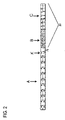
FIG. 1 shows a schematic side view of an
挿入チューブ2は、円筒形の管状すなわちチューブ状の形成物である。
The
以下に、挿入チューブ2が患者に差し込まれる方向に、挿入チューブについてより詳しく説明する。挿入チューブ2は、遠端から先に差し込まれる。
In the following, the insertion tube will be described in more detail in the direction in which the
挿入チューブ2は、遠端側に屈曲部Aを備える。屈曲部Aは、1または複数の制御ワイヤ(1本の引張ワイヤまたは複数の引張ワイヤ)によって、挿入チューブ2の遠端側部分に対して側方に折り曲げることができる。制御ワイヤすなわち引張ワイヤ(以下では「制御ワイヤ」とする)は、挿入チューブ2の内部において、挿入チューブ2の内周面で挿入チューブ2の長手方向に案内され、取り付けられている。
The
制御ワイヤの遠端は、屈曲部Aの遠端側で固定されている。制御ワイヤの近端は、コントロール体3に配置された制御部材と接続されている。この制御部材は、屈曲部Aの所望の折り曲げを行うために、制御ワイヤを緊張させる。
The distal end of the control wire is fixed on the distal side of the bend A. The proximal end of the control wire is connected with a control member arranged on the
屈曲部Aの近端側では、挿入チューブ2が柔軟性チューブ部材として形成され、近端側の受動可撓部20を形成する。挿入チューブ2を挿入すると、受動可撓部20が屈曲部Aに追従する。
On the proximal side of the bend A, the
図1において、受動可撓部20が、その長手方向に沿って異なる柔軟性を有するゾーンの形で形成されていることが示されている。例えば、受動可撓部20は、近端側方向に見て第1ゾーンBと第2ゾーンCと第3ゾーンDとを有する。第1ゾーンBは、遠端側領域をなし、第2ゾーンCは中間領域をなし、第3ゾーンDは近端側領域をなす。
In FIG. 1 it is shown that the
図2の部分図に、第3ゾーンDは示されていない。 The third zone D is not shown in the partial view of FIG.
屈曲部Aと第1ゾーンBとの間の屈曲を回避するために、第1ゾーンBは、殊に、受動可撓部20のゾーンのなかでも最大の柔軟性を備えている。第1ゾーンBが非常に高い柔軟性を備えているので、屈曲部Aと第1ゾーンBとの間に急激な柔軟性の遷移は生じない。
In order to avoid flexing between the bend A and the first zone B, the first zone B in particular has the greatest flexibility of the zones of the
第2ゾーンCは、第1ゾーンBより柔軟性が低い。第3ゾーンDもまた第2ゾーンCより柔軟性が低い。 The second zone C is less flexible than the first zone B. The third zone D is also less flexible than the second zone C.
本発明による挿入チューブ2は、一体に形成されている。すなわち、屈曲部Aから受動可撓部20への遷移部で2つの部材が接合されるものではない。したがって、遠端側の屈曲部Aと3つのゾーンA、B、Cを有する近端側の受動可撓部20とが、単一の管すなわちチューブから形成されている。
The
挿入チューブ2は、近端側でコントロール体3の遠端に取り付けられている。挿入チューブ2は、コントロール体3に、例えば固定リングによって、封止リングによって、または直接取り付けられていてもよい。挿入チューブ2は、コントロール体3に、例えば貼着または螺着されてもよい。コントロール体3は、制御ワイヤすなわち引張ワイヤを制御するための第1制御部材としての第1制御ホイールFと、制御ワイヤすなわち引張ワイヤを制御するための第2制御部材としての第2制御ホイールGとを有している。第1制御ホイールFは、制御ワイヤすなわち引張ワイヤを引っ張ることによって、第1平面において屈曲部Aを折り曲げることができる(例えば、図1において観察者に向かって、および観察者から離れる方向に)。第2制御ホイールGは、制御ワイヤすなわち引張ワイヤを引くことによって、第1平面に対して垂直の第2平面において屈曲部Aを折り曲げることができる(例えば、図1において上下に)。
The
屈曲部Aを、例えば200~270度折り曲げることができる。大抵の用途にはこれで十分である。特殊な形状では、屈曲部Aを300度折り曲げることさえできる。 The bending portion A can be bent 200 to 270 degrees, for example. This is sufficient for most applications. In special geometries, bend A can even be bent 300 degrees.
以下に、本発明による挿入チューブ2とその製造について詳しく説明する。
In the following, the
挿入チューブ2全体は、単一の管材すなわちチューブ部材(以下に、これを単に管材と呼ぶ)から形成されている。管材は、殊に比較的硬質の材料からなる管である。ステンレス鋼からなる管が特に好ましい。しかし硬質プラスチックからなる管も使用することができる。基本的には、医療目的で使用可能なあらゆる材料を利用することができる。
The
レーザ切断機によって、管材には以下に詳しく説明するような切り込みが設けられる。以下に詳しく説明するように、切え込みを設けた後に、管材の特定の部分が曲げられる。挿入チューブ2全体の基体の製造は、切り込みを設けることや曲げること以外の方法工程を必要としない。その後、挿入チューブ2の基体に制御ワイヤを設け、外装部材で被覆することができる。
A laser cutter cuts the tubing as described in detail below. As will be described in detail below, certain portions of the tubing are bent after the cuts are made. The manufacture of the base body of the
以下に、挿入チューブ2の個々の部分について詳しく説明する。
Below, the individual parts of the
[受動可撓部20]
受動可撓部20は、本発明による挿入チューブ2の近端部をなす。受動可撓部20は、それぞれ異なる柔軟性を有する3つのゾーンB、C、Dを有している。
[Passive Flexible Section 20]
A passive
図3は、受動可撓部20の3つのゾーンB、C、Dのうちの1つを形成する可能性の側面図を示す。
FIG. 3 shows a side view of the possibility of forming one of the three zones B, C, D of the
受動可撓部20は、受動可撓部20の軸に対して垂直に形成された複数の切り込みSを備えている。より厳密に言えば、切り込みSは、切り込み201が上から管材の軸に対して垂直に管材を通って中心軸領域の手前で終わる深さまで行われるように形成されている。さらに、切り込み202は、下から管材の軸に対して垂直に管材を通って同様に中心軸領域の手前で終わる深さまで行われる。切り込み201および202は一平面上にあり、これらの切り込みの端は互いに、そのままの中間スペース203を介して向かい合う。中間スペース203は、管材の中心軸領域にある切断されない中間スペースである。
The passive
さらに、切り込み201および202の場合と類似に、切り込み204は、一方の(例えば左)側から(切り込み204は観察者の側からの切り込みを示す)管材を通って管材の軸に対して垂直に、中心軸領域の手前で終わる深さまで行われる。さらに、反対(例えば右)側の切り込みは(この切り込みは図の面の向こう側にあるため図3に図示されない)管材を通って管材の軸に対して垂直に、同様に中心軸領域の手前で終わる深さまで行われる。これらの切り込みは一平面上にあり、かつこれらの切り込みの端は互いに、同様にそのままの中間スペースを介して向かい合う。これらの中間スペースも同様に、管材の中心軸領域にある切断されない中間スペースである。
Further, similar to
切り込み201、202間の中間スペース203、および切り込み204とこれに関連する反対側の切り込みとの間の中間スペースは、管材の周方向に沿って90度ずれている。
切り込み201、202、および切り込み204とこれに関連する反対側の切り込みとは隣り合い、かつ受動可撓部20におけるそれぞれのゾーンの長さにわたって互いに交互になる(図3参照)。
The
したがって、受動可撓部20は、その長手軸に対して横方向に、中間スペースを中心として曲げることが可能である。
The passive
個々のゾーンB、C、Dは、切り込みSの間隔、すなわち切り込みSの密度が、長手方向に様々に形成されているという点で区別される。 The individual zones B, C, D are distinguished in that the spacing of the cuts S, ie the density of the cuts S, is made differently in the longitudinal direction.
ゾーンBにおいて、切り込みSの間隔は最小である。それにより、ゾーンBにおいて切り込みSの密度が最大となる。 In zone B, the spacing of cuts S is minimal. Thereby, the density of the cuts S in the zone B is maximized.
ゾーンCにおいて、切り込みSの間隔はゾーンBにおけるより大きい。ゾーンDにおいて、切り込みSの間隔はゾーンCにおけるより大きい。 In zone C the spacing of the notches S is greater than in zone B. In zone D the spacing of the incisions S is greater than in zone C.
それにより、ゾーンBにおける柔軟性および可撓性はゾーンCにおけるより高い。さらに、ゾーンCにおける柔軟性および可撓性は、ゾーンDにおけるより高い。換言すると、受動可撓部20のそれぞれのゾーンの柔軟性および可撓性は、近端側方向に低下する。
Thereby the softness and flexibility in zone B is higher than in zone C. In addition, softness and flexibility in Zone C is higher than in Zone D. In other words, the softness and flexibility of each zone of passive
ゾーンDは、近端側に、切り込みが設けられていない領域を備えている。この領域は、コントロール体Jへの遷移部をなす。 Zone D comprises an area on the proximal side where no cuts are provided. This area forms the transition to the control body J.
[屈曲部Aから受動可撓部20への遷移部]
屈曲部Aから受動可撓部20への遷移領域は、図2に領域Kとして示されている。この領域Kで屈曲部Aが終わる。換言すると、領域Kの遠端から屈曲部Aが始まる、すなわち領域Kの遠端が屈曲部Aの最も近端側になる。
[Transition from bending part A to passive flexible part 20]
The transition region from flexure A to
図2に示されるように、この領域Kにおいて、管材の壁面がアルファベットCを逆にした形の切り込み70によって切り込まれている。換言すると、切り込み70は、管材において不完全な円形の形に切り込まれている。切り込み70の円形は、遠端側が最後まで切られていない。切り込み70の最後まで切られていない遠端側は、接合板72のためのヒンジ71をなす。接合板72は、下耳73と上耳74と接合板中央片75とを有する。接合板中央片75の上側に下耳73が隣接する。接合板中央片75の下側には上耳74が隣接する。
As shown in FIG. 2, in this region K, the wall surface of the tube is cut with a
接合板72は、次のように製造される。切り込み70の場所が定められる。切り込み70の中心に穴77が切断される。切り込み70がレーザで図2に示されるように形成される。接合板中央片75が、裏側から、すなわち管材の内側からねポンチによって支持される。下耳73が接合板中央片75に相対して内側へ90度曲げられる。その際、接合板中央片75に相対する耳73の曲げ線は、管材の軸に対して平行に延びる(図2および図4において左右方向)。上耳74も同様に、接合板中央片75に相対して内側へ90度曲げられる。接合板中央片75に相対する耳74の曲げ線も同様に、管材の軸に対して平行に延びる。その後、接合板中央片75が内側へ90度曲げられる。管材に相対する接合板中央片75の曲げ線は、管材の軸に対して垂直の断面上に延びる(図2および図4において上下方向)。換言すると、接合板中央片75は、ヒンジ71で内側へ90度曲げられる。接合板75は、特に、下耳73の遠端側の側縁および上耳74の遠端側の側縁が管材の内周に当接するまで内側に曲げられる(図5参照)。
The joining
接合板72は、ガイドばね8の支持部として用いられる。特に、接合板中央片75の近端側面は、ガイドばね8の遠端側端のための当接面をなす。2つの耳73、74は、接合板中央片75を支持し、ガイドばね8によって作用する押圧力を受け、この力を管材の内周面へ伝える。
The
接合板中央片75は、中心穴77を具備する。穴77は、制御ワイヤより大きい直径を有し、ガイドばね8より小さい直径を有する。制御ワイヤは、受動可撓部20においてガイドばね8に案内され、穴70を通り抜け、さらに屈曲部A内へ延在する。
The splice plate
領域Kにおいて、使用される制御ワイヤの数(この実施例では4本)の接合板72が設けられる。接合板72は、管材の周方向に均等に配分されている。
In the region K, a
[屈曲部A]
屈曲部Aの詳細な構造が図6~図11に示されている。
[Flection A]
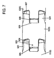
A detailed structure of the bent portion A is shown in FIGS. 6 to 11. FIG.
屈曲部Aは、屈曲部Aの長手方向に配置されている別個の継手6を有する。個々の継手6は相対して旋回可能である。図6および図7において、相前後して配置された3つの継手6、すなわち継手61と、継手61の近端側に継手62と、継手62の近端側に継手63とが示されている。
The bend A has a separate joint 6 arranged longitudinally of the bend A. As shown in FIG. The
継手6は、最も遠端側にある継手6および最も近端側にある継手6を除いて、互いに同じに形成されている。
The
以下に、継手62をもとにして、それぞれの継手6の構造について説明する。 The structure of each joint 6 will be described below based on the joint 62 .
継手62は、レーザ切断によって上記の管材の一部として形成されている。継手62は、管材の周囲に遠端側の境界線601、602、603、604、605と近端側の境界線606、607、608、609とを有する。
Joint 62 is formed as part of the tubing by laser cutting. The fitting 62 has
個々の遠端側の境界線は、円形頭線601と、2つの首線602と、2つの肩線603と、2つの腕線604と、1つの腕終端線605と、から構成されている。より厳密に言えば、継手62の遠端側は次のように形成されている。円形頭線601は、近端側の各側で首線602へ遷移する不完全な円形をなす。2つの首線602の各々には、管材の軸に対して略垂直に延びる肩線603が続く。2つの肩線603の各々には、管材の軸に対して略平行に遠端側方向に延びる腕線604が続く。腕線604の2つの遠端は、再び管材の軸に対して垂直に延びる腕終端線605によって接続されている。
Each distal boundary line consists of a circular head line 601, two
それにより、継手62は本体621を有し、本体から遠端側に向かって第1頭622、第1腕623、第2頭622、および第2腕623が、継手62の軸に対して垂直に延びる想定された円周線に沿って、それぞれ90度だけ突出する。したがって、頭622、622は、第1の想定平面上に延在する。腕623、623は、第1の想定された平面に対して90度だけずらした第2想定平面上に延在する。継手62の2つの頭622、622は、これらの遠端側にある継手61のための旋回軸をなす。
The joint 62 thereby has a
各頭622は、遠端側で頭線601によって形成されている。頭622と本体621との間には、首線602によって狭窄部が形成されている。それぞれの頭622は、遠端方向でそれぞれの腕623よりさらに先へ突出する。
Each
個々の近端側の境界線は、1つの曲がった足線606と、2つの底線607と、2つの直線の足線608と、1つの腹線609とから構成される。より厳密に言えば、継手62の近端側は、次のように形成されている。
Each proximal border consists of one
曲がった足線606が、近端側で開いた不完全な円形を形成する。不完全な円形の開端には、曲がった足線606が、それぞれ管材の軸に対して略垂直に延びる底線607へそれぞれ遷移する。
A
2つの底線607の各々に、管材の軸に対して略平行に遠端方向に延びる直線の足線608が続く。直線の足線608の2つの遠端は、再び管材の軸に対して垂直に延びる腹線609によって接続されている。
Each of the two
これにより、継手62は、本体621の近端側に、近端方向に延在する2つの足624を有する。各足624は、延在方向に直線の足線608の直線側と、曲がった足線606の湾曲側とを有する。
Thereby, the joint 62 has two
2つの直線の足線608間の領域には、近端側にある継手63の腕が長手方向に摺動可能に配置されている。2つの曲がった足線606間の領域において、近端側にある継手63の頭が長手方向に不動に保持されている。曲がった足線の内周と円形状に成形された頭線の外周との間の遊びにもとづいて、場合によってはわずかな動きが可能である。
In the area between the two
図7に示されるように、屈曲部Aが曲げられていない状態にあるとき、腹線609は、近端側にある継手63の腕線605から離隔されている。近端側にある継手63の腕線605と腹線609とは、互いに平行である。
As shown in FIG. 7, when flexure A is in its unbent state, abdomen 609 is spaced from
図7に示されるように、屈曲部Aが曲げられていない状態にあるとき、底線607は、近端側にある継手63の肩線603から離隔されている。
As shown in FIG. 7, when flexure A is in its unbent state,
図7に示されるように、近端側にある継手63の底線607と肩線603とは、互いに平行であってもよいし、または互いに略平行であってもよいし、または互いにわずかな角度をなしてもよい。近端側にある継手63の底線607と肩線603との間に、一本の切断線が作製されただけでなく、管材の材料が四角片として切り抜かれている。
As shown in FIG. 7, the
それぞれの頭622は、隣接する継手6と連結される連結部を形成する。足624は、継手6の相対する軸方向の運動が可能になるように、隣接する継手6と係合するガイド部を形成する。
Each
図10は、それぞれの継手6を有する屈曲部Aの上面図を示す。上面図において、継手6の頭622が見て取れる。
FIG. 10 shows a top view of bend A with
図11は、それぞれの継手6を有する屈曲部Aの側面図を示す。側面図において、継手6の足624が見て取れる。
FIG. 11 shows a side view of bend A with
最も遠端側にある継手6は頭をもたず、図2および図10~図14に示されている。 The distal-most joint 6 is headless and is shown in FIGS. 2 and 10-14.
最も近端側にある継手6は、足をもたず、図2、図4および図11に示されている。 The proximal-most joint 6 has no legs and is shown in FIGS.
この実施形態において、屈曲部Aが2つの折り曲げ方向、つまり図6および図7(および図10)において上下に折り曲げられていてもよく、継手6のそれぞれの頭622は、継手6の曲げ軸をなす。換言すると、図10において、屈曲部Aは上下に旋回可能である。図11において、屈曲部Aは、観察者の向かって、かつ観察者から離れる方向に、旋回可能である。 In this embodiment, bend A may be bent in two bending directions, namely up and down in FIGS. Eggplant. In other words, in FIG. 10, the bent portion A can pivot up and down. In FIG. 11, bend A is pivotable towards and away from the viewer.
図8および図9に示されるように、腹線609は、ワイヤガイド接合板630のためのヒンジ部を形成する。ワイヤガイド接合板630は、腹線609から延在する。
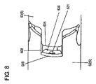
As shown in FIGS. 8 and 9,
ワイヤガイド接合板630のために、直線の足線608に沿って、近端側にある継手63の腕終端線605まで延在する材料部が除去される。ワイヤガイド接合板630は、腹線609に枢着され、内側へ90度曲げられる。ワイヤガイド接合板630は、中心穴631を具備する。穴631は、制御ワイヤより大きい直径を有する。
For the wire
継手6の各々は、穴631を有するワイヤガイド接合板630を備え、それにより、ワイヤガイド接合板630が、特定の制御ワイヤのために、屈曲部Aの長手方向に相前後して配置されている。引っ張りワイヤガイド接合板630は、制御ワイヤが支持されるガイド突出部として用いられる。それにより、ワイヤガイド接合板630は、これらに割り当てられた制御ワイヤを屈曲部Aに通す。
Each of the
継手6は、図10に示されるように、その頭が近端側方向を指すように屈曲部Aに配置されていてもよい。これに代えて、継手6は、図6に示されるように、その頭が遠端側方向を指すように屈曲部Aに配置されていてもよい。 The joint 6 may be arranged at the bend A with its head pointing in the proximal direction, as shown in FIG. Alternatively, the joint 6 may be arranged at the bend A with its head pointing in the distal direction, as shown in FIG.
屈曲部Aの遠端が図12~図14に示されている。図12~図14において、屈曲部Aの最も遠端側にある継手69が見て取れる。最も遠端側にあるこの継手69に、制御ワイヤ9の遠端が固定されている。制御ワイヤ9は、コントロール体3から最も遠端側にある屈曲部Aの継手69まで延在する。
The distal end of flexure A is shown in FIGS. 12-14. 12-14, the farthest joint 69 of bend A can be seen. The distal end of the
[制御ワイヤの取り付け]
制御ワイヤ9の詳細な取り付けが、図15および図16に示されている。
[Installation of control wires]
A detailed mounting of the
制御ワイヤ9は、コントロール体3において制御ホイールGに取り付けられている。制御ホイールGを緊張方向に回転させると、制御ワイヤ9が緊張される。制御ホイールGを緊張方向とは反対の緊張解除方向に回転させると、制御ワイヤ9が緊張解除される。
A
制御ワイヤ9は、コントロール体3から来て挿入チューブ2において継手69まで延びるように延在して、第1セクション91を形成する。制御ワイヤ9のこの第1セクション91は、挿入チューブ2の内周に沿って延びる。制御ワイヤ9のこの第1セクション91は、図15に参照符号91で示されている。継手69の遠端には、継手69の周壁を貫通し、継手69の長手方向に延在するスロット691が形成されている(図13参照)。他の類似のスロット692は、継手69の遠端に、スロット691の正反対の向かい側に位置するように設けられている。
The
制御ワイヤ9は、継手69の内周において遠端方向に延在し、スロット691を外側に通り抜け、継手69の外周で、継手69の周方向にスロット692まで曲がりくねり、スロット692を内側に通り抜け、コントロール体3において継手69の内周で近端方向に制御ホイールGにまで延在する。
The
したがって、制御ワイヤ9は、コントロール体3における制御ホイールGからスロット691まで延在する第1セクション91と、スロット691から継手69の外周で継手69の周方向にスロット692まで延在する第2セクション92と、スロット692からコントロール体3における制御ホイールGまで延在する第3セクション93とに分けられる。
Thus, the
制御ホイールGを緊張方向に回転させることによって制御ワイヤ9が緊張し、それにより継手69に固定された第3セクション93が近端方向に押しやられるので、屈曲部Aが折り曲げられる。したがって、制御ワイヤ9の第3セクション93は、制御ワイヤ9の遠端側の固定セクションを形成する。
Rotation of the control wheel G in the tensioning direction tensions the
[製造方法]
本発明による挿入チューブ2は、レーザによる切削加工により、単一の管材から製造される。管材は、例えばステンレス鋼または適当な硬質プラスチックなどの比較的硬質の材料から製造される。切削加工によって、硬質の管材は柔軟になるが、その剛性は保たれる。
[Production method]
The
切削加工は、近端側の受動可撓部20におけるそれぞれの側方の切り込みSと、穴77と、遷移領域Kにおける切り込み70と、穴631と、遠端側の屈曲部Aにおけるそれぞれの継手6と、スロット691、692とを作製する。この順序は限定と解釈されるべきでない。例えばスロット691、692は、継手6より前に切削加工されてもよい。さらに、切削加工の順序は、逆にされてもよい。
Machining includes respective lateral cuts S in the proximal
管材の柔軟性と、さらに剛性とは、切削加工の形状、配列、および大きさにより制御することができる。 The flexibility, and also the stiffness, of the tubing can be controlled by the shape, alignment, and size of the cuts.
それぞれの切削加工の場所を予め計算および予め決定することができる。プログラム可能なレーザ切削加工機において、挿入チューブ2を自動的に作製するために、それぞれの拙作加工ごとに予め設定されたデータが入力されてもよい。
The location of each cut can be pre-calculated and pre-determined. In a programmable laser cutting machine, preset data may be entered for each machining process in order to automatically fabricate the
個々の継手6が完全に切断されて、形状結合的に接続されているだけの、物理的に互いに分離した体をなす。
The
管材のレーザ切削加工後、接合板72とワイヤガイド接合板630とが内側へ曲げられる。これにより、挿入チューブ2の中間製品が完成する。
After laser cutting the tubing, the
次に、挿入チューブ2の中間製品に、制御ワイヤ9を挿入および取り付けることができる。挿入チューブ2の中間製品は、コントロール体3に取り付けられてもよい。さらに、挿入チューブ2の中間製品には、電気的制御部を遮蔽するために、挿入チューブ2の中間製品のための未加工体を取り囲む殊に金属からなるカバーが張設され、このカバーの上に、プラスチックまたはゴムからなる弾性の外装が張設されてもよい。プラスチックまたはゴムからなる弾性の外装を熱収縮させてもよい。
A
[第2の実施形態]
以下に、図17~図19を参照しながら、本発明の第2の実施形態について説明する。
[Second embodiment]
A second embodiment of the present invention will be described below with reference to FIGS. 17 to 19. FIG.
第1の実施形態では、曲げ区分において、個々の継手は、切削加工によって、それらが内視鏡の延在方向において凸部および凹部を有するように形成されている。凸部は、継手の旋回運動を可能にするために、隣接する継手の凹部に着座する。換言すると、第1の実施形態では、個々の継手が、形状結合的に接続されている。 In a first embodiment, in the bending section the individual joints are formed by machining in such a way that they have a convexity and a concaveness in the direction of extension of the endoscope. The protrusions seat in recesses in adjacent joints to allow pivoting movement of the joints. In other words, in the first embodiment the individual joints are positively connected.
図17~図19は、第2の実施形態の曲げセクションとしての屈曲部A’を示す。第2の実施形態では、屈曲部A’には直線の切り込み801、802、811、812のみが設けられている。
Figures 17-19 show the bend A' as a bending section of the second embodiment. In the second embodiment, only
屈曲部A’は、屈曲部A’の軸に対して垂直に形成された複数の切り込み801、802を有する。より厳密に言えば、切り込み801、802は、切り込み801が上から管材を通って管材の軸に対して垂直に、中心軸領域の手前で終わる深さまで届くように形成されている。さらに、切り込み802は、下から管材を通って、管材の軸に対して垂直に、同様に中心軸領域の手前で終わる深さまで届くように形成されている。切り込み801および802は一平面上にあり、これらの切り込みの端は、そのままの中間スペース803を介して互いに向かい合う。中間スペース803は、管材の中心軸領域における切り込まれない中間スペースである。切り込み801は、互いに平行である。切り込み802も同様に互いに平行である。
Bend A' has a plurality of
直線の切り込み801、802は継手として機能し、屈曲部A’の曲げ運動を可能にする。
The
屈曲部A’の長手方向に相前後して位置する所定数の切り込み801(802も当然同様)が、1つのグループにまとめられている。図18において、それぞれ10個の切り込み801が1つのグループに属し、切り込み801、802の数は、グループごとに任意に適当に選定することができる。1つのグループが有する切り込み801、802が多ければ多いほど、このグループの領域における曲げ角度が大きくなる。
A predetermined number of notches 801 (the same applies to 802, of course) that are positioned one behind the other in the longitudinal direction of the bend A' are grouped together. In FIG. 18, ten
切り込み801、802のそれぞれのグループは、短い切り込み811、812を有するリング部805によって、屈曲部A’の長手方向に区画されている。
Each group of
より厳密に言えば、短い切り込み811、812は、図17に示されるように、短い切り込み811が上から、管材を通って垂直に、管材の軸の方向に対して垂直に、非常に短い深さまで行われるように形成されている。この短い深さは、例えば管材の直径の1/10から1/20であってもよい。それにより、短い切り込み811が上から示されている図18に示されるように、それぞれの切り込み811、812の長さが短くなる。短い切り込み811、812の長さは、任意に適当に選定することができる。
More precisely, the
さらに、それぞれの下からの短い切り込み812は、上からの短い切り込み811の場合と同様に形成される。切り込み811は、互いに平行である。切り込み812も同様に、互いに平行である。
Further, each
短い切り込み811および812はそれぞれ対をなし、それぞれ一平面上に位置し、それらの端が互いに、リング部805を形成するそのままの中間スペースを介して、互いに向かい合う。リング部805は、一対の短い切り込み811、812しか有していない管の部分である。
The
それぞれの短い切り込み811、812に隣接する管材の部分は、帯部を形成する。図19に示されるように、この帯部は、これが管材の管中心に向かって曲げられる場合に、ワイヤガイド接合板880を形成する。したがって、引っ張りワイヤは、ワイヤガイド接合板880の帯部の外に向いた面と管材の長手方向に隣接する内周面との間に形成された中間スペースで案内されてもよい。
The portion of tubing adjacent each
その際、直線の切り込み801、802は、剛性が第1の実施形態と類似であるように屈曲部A’に設けられていてもよい。
直線の切り込み801、802、811、812を設けることによって、継手およびワイヤガイド接合板を製造するために必要な機械稼働時間を大幅に低減することができる。それにより製造コストが低減される。
By providing
[他の代替案]
以上の実施形態において、受動可撓部20は、近端側方向に見て、異なった柔軟性を有する第1ゾーンBと第2ゾーンCと第3ゾーンDからなる。異なった柔軟性を有するゾーンすなわち領域の数は、限定されない。受動可撓部20は、異なった柔軟性を有するそれよりも多いかまたは少ないゾーンを有していてもよい。本発明は、受動可撓部20が一貫して同じである一定の柔軟性を有する挿入チューブにも適用可能である。
[Other alternatives]
In the above embodiments, the passive
以上の実施形態において、挿入チューブ2の管材は、ステンレス鋼から形成されている。本発明はそれに限定されない。挿入チューブ2の材料は、例えば剛性プラスチックなど任意の十分に剛性材料であってもよい。これに代わる他の実施形態では、ニチノール(ニッケルチタン合金)を管材として使用することができる。この材料は、とりわけいわゆる超弾性という特性を有し、すなわち、この材料は、曲がったままになることなく広い領域において弾性変形することができる。
In the above embodiments, the tubular material of the
一代替案として、レーザ切削機によって管材に切削加工を行うことができる。このような切削加工は、非常に正確に行うことができる。したがって、レーザでの製造が好ましい。しかし基本的に、これらの切削加工は、例えば鋸、ワイヤソーなどの、他の製造方法で製作されてもよい。 As an alternative, the tubing can be cut by a laser cutting machine. Such cutting can be performed very precisely. Laser fabrication is therefore preferred. Fundamentally, however, these cuttings may also be produced by other manufacturing methods, such as saws, wire saws, and the like.
以上の実施形態において、屈曲部Aは、2つの折曲方向、すなわち図6および図7において上下に、折り曲げることができる。一代替案として、個々の継手6は、継手6から継手6へ、その頭622を、屈曲部Aの軸(継手6の軸)を中心として90度回転させてずらして形成されてもよい。この選択肢では、屈曲部Aは、4つの折曲方向に、すなわち図6および図7において上下に、かつ観察者に向かって、および観察者から離れる方向に、折り曲げることができる。
In the above embodiments, the bend A can be bent in two bending directions, namely up and down in FIGS. As an alternative, each joint 6 may be formed with its
屈曲部Aを4つの折曲方向に折り曲げることができるという代替案では、挿入チューブ2において、互いに90度ずれて延びる2つの制御ワイヤ9を使用することができる。その場合、継手92は、同様に互いに90度ずらした4つの遠端側スロットを備える。
In the alternative that the bend A can be bent in four bending directions, two
以上の実施例において、上述の形のそれぞれの継手6が形成されている。本発明は、継手6の形に限定されていない。互いに連結されており、かつ屈曲部Aの偏向運動を可能にする継手が屈曲部Aに切削加工されることで十分である。
In the above examples,
本発明は、十二指腸スコープ、胃内視鏡、大腸内視鏡、または類似の内視鏡に有利に適用可能である。本発明の原理は、任意の他の種類の内視鏡にも適用することができる。 The present invention is advantageously applicable to duodenoscopes, gastroscopes, colonoscopes or similar endoscopes. The principles of the invention can also be applied to any other type of endoscope.
本発明の原理は、挿入チューブを使用する他の医療装置にも適用可能である。 The principles of the present invention are also applicable to other medical devices that use insertion tubes.
1 内視鏡
2 挿入チューブ
3 コントロール体
6 継手
8 ガイドばね
9 制御ワイヤ
20 受動可撓部
61 継手
62 継手
63 継手
69 最も遠端側にある継手
70 切り込み
71 ヒンジ
72 接合板
73 下耳
74 上耳
75 接合板中央片
77 穴
91 制御ワイヤの第1セクション
92 制御ワイヤの第2セクション
93 制御ワイヤの第3セクション
201 上からの切り込み
202 下からの切り込み
203 切断されない中間スペース
204 側方からの切り込み
601 頭線
602 首線
603 肩線
604 腕線
605 腕線
606 曲がった足線
607 底線
608 直線の足線
609 腹線
621 本体
622 頭
623 腕
624 足
630 ワイヤガイド接合板
631 中心穴
691 スロット
692 スロット
801 上からの切り込み
802 下からの切り込み
803 切断されない中間スペース
805 短い切り込みを有するリング区分
811 上からの短い切り込み
812 下からの短い切り込み
880 ワイヤガイド接合板
A 屈曲部
A’ 屈曲部
B 第1ゾーン(遠端側領域)
C 第2ゾーン(中央領域)
D 第3ゾーン(近端側領域)
F 第1制御ホイール(第1制御部材)
G 第2制御ホイール(第2制御部材)
J コントロール体ハウジング
K 遷移領域
S 受動可撓部における側方の切り込み
1
C Second Zone (Central Area)
D 3rd zone (proximal region)
F first control wheel (first control member)
G second control wheel (second control member)
J Control body housing K Transition area S Lateral notch in passive flexure
Claims (17)
前記挿入チューブ(2)は、近端側の受動可撓部(20)と遠端側の屈曲部(A)とを有し、
前記受動可撓部(20)と前記屈曲部(A)とを含む前記挿入チューブの全体を単一の管材から形成し、
前記遠端側の屈曲部(A)に、周壁を切ることにより複数の継手(6)を作製し、
前記近端側の受動可撓部(20)に隣接して配置されたコントロール体(3)によって、前記管材の内周面に引張ワイヤ(9)を配置し、前記引張ワイヤを、前記遠端側の屈曲部(A)の最も遠い遠端側にある継手(69)において、前記管材の壁における第1スロット(691)を通って前記管材の外周へ案内し、前記管材の外周を周って前記管材の壁において第2スロット(692)へと、前記管材の内周へ案内し、その際、前記第2スロット(692)が前記第1スロット(691)に対して180度反対にあり、前記引張ワイヤを、前記管材の内周面において再び前記コントロール体(3)へ戻す、内視鏡挿入チューブの製造方法。 A method of manufacturing an insertion tube (2) for an endoscope, comprising:
said insertion tube (2) having a proximal passive flexible section (20) and a distal bending section (A),
forming the entire insertion tube, including the passive flexible portion (20) and the bend (A), from a single piece of tubing ;
A plurality of joints (6) are produced by cutting the peripheral wall at the bent portion (A) on the far end side,
A control body (3) positioned adjacent to the proximal passive flexure (20) places a puller wire (9) on the inner circumference of the tubing, the puller wire being connected to the distal end. At the farthest end joint (69) of the side bend (A), it guides through a first slot (691) in the wall of the tubing to the circumference of the tubing and wraps around the circumference of the tubing. to a second slot (692) in the wall of the tubing to the inner circumference of the tubing, wherein the second slot (692) is 180 degrees opposite to the first slot (691). A method for manufacturing an endoscope insertion tube , wherein the pulling wire is returned to the control body (3) on the inner peripheral surface of the tube.
前記挿入チューブ(2)は、近端側の受動可撓部(20)と遠端側の屈曲部(A)とを有し、
前記受動可撓部(20)と前記屈曲部(A)とを含む前記挿入チューブ(2)の全体が単一の管材から形成され、
前記遠端側の屈曲部(A)の周壁に複数の継手(6)が作製され
前記近端側の受動可撓部(20)に隣接して配置されたコントロール体(3)によって、前記管材の内周面に引張ワイヤ(9)が配置され、前記引張ワイヤは、前記遠端側の屈曲部(A)の最も遠い遠端側にある継手(69)において、前記管材の壁における第1スロット(691)を通って前記管材の外周へ案内され、前記管材の外周を周って前記管材の壁において第2スロット(692)へと、前記管材の内周へ案内され、その際、前記第2スロット(692)が前記第1スロット(691)に対して180度反対にあり、前記引張ワイヤは、前記管材の内周面において再び前記コントロール体(3)へ戻される、内視鏡。 An endoscope having an insertion tube,
said insertion tube (2) having a proximal passive flexible section (20) and a distal bending section (A),
the entire insertion tube (2) including the passive flexible portion (20) and the bend (A) is formed from a single piece of tubing ;
A plurality of joints (6) are fabricated on the peripheral wall of the distal bend (A).
A control body (3) positioned adjacent to the proximal passive flexure (20) places a puller wire (9) on the inner circumference of the tubing, said puller wire At the farthest end joint (69) of the side bend (A), the tube is guided through a first slot (691) in the wall of the tubing to the circumference of the tubing and circumnavigates the circumference of the tubing. into a second slot (692) in the wall of the tube, and into the inner circumference of the tube, wherein the second slot (692) is 180 degrees opposite to the first slot (691). , the pull wire is returned to the control body (3) again at the inner peripheral surface of the tube .
Applications Claiming Priority (3)
| Application Number | Priority Date | Filing Date | Title |
|---|---|---|---|
| DE102017123975.8 | 2017-10-16 | ||
| DE102017123975.8A DE102017123975A1 (en) | 2017-10-16 | 2017-10-16 | Method of making an introducer tube of an endoscope and endoscope with an introducer tube |
| PCT/IB2018/001155 WO2019077402A2 (en) | 2017-10-16 | 2018-10-15 | Method for producing an iendoscope insertion tube and endoscope comprising an insertion tube |
Publications (2)
| Publication Number | Publication Date |
|---|---|
| JP2020536608A JP2020536608A (en) | 2020-12-17 |
| JP7202370B2 true JP7202370B2 (en) | 2023-01-11 |
Family
ID=64051611
Family Applications (2)
| Application Number | Title | Priority Date | Filing Date |
|---|---|---|---|
| JP2020518811A Active JP7287954B2 (en) | 2017-10-16 | 2018-10-15 | Manufacturing method of insertion tube for endoscope and endoscope provided with insertion tube |
| JP2020518684A Active JP7202370B2 (en) | 2017-10-16 | 2018-10-15 | Method for manufacturing endoscope insertion tube and endoscope provided with insertion tube |
Family Applications Before (1)
| Application Number | Title | Priority Date | Filing Date |
|---|---|---|---|
| JP2020518811A Active JP7287954B2 (en) | 2017-10-16 | 2018-10-15 | Manufacturing method of insertion tube for endoscope and endoscope provided with insertion tube |
Country Status (9)
| Country | Link |
|---|---|
| US (2) | US11931001B2 (en) |
| EP (2) | EP3697284B1 (en) |
| JP (2) | JP7287954B2 (en) |
| CN (2) | CN111163677B (en) |
| AU (2) | AU2018353498B2 (en) |
| CA (2) | CA3077490A1 (en) |
| DE (1) | DE102017123975A1 (en) |
| ES (2) | ES2964032T3 (en) |
| WO (2) | WO2019077401A2 (en) |
Families Citing this family (11)
| Publication number | Priority date | Publication date | Assignee | Title |
|---|---|---|---|---|
| WO2018098465A1 (en) | 2016-11-28 | 2018-05-31 | Inventio, Inc. | Endoscope with separable, disposable shaft |
| DE102017123975A1 (en) | 2017-10-16 | 2019-04-18 | Hoya Corporation | Method of making an introducer tube of an endoscope and endoscope with an introducer tube |
| CN108577789A (en) * | 2018-05-17 | 2018-09-28 | 上海安清医疗器械有限公司 | Endoscope |
| DE102018127227B4 (en) * | 2018-10-31 | 2022-06-15 | Hoya Corporation | Method for manufacturing an insertion tube of an endoscope and an endoscope with an insertion tube |
| JP2022544554A (en) * | 2019-08-15 | 2022-10-19 | オーリス ヘルス インコーポレイテッド | Medical device with multiple bends |
| USD1018844S1 (en) | 2020-01-09 | 2024-03-19 | Adaptivendo Llc | Endoscope handle |
| CN111761609B (en) * | 2020-07-08 | 2022-06-03 | 天津大学 | Flexible continuum robot based on contact auxiliary structure |
| CN112336297B (en) * | 2020-10-31 | 2022-06-07 | 同济大学 | Method and system for controlling in-vivo introduction device, and computer-readable storage medium |
| US20240108422A1 (en) * | 2021-01-26 | 2024-04-04 | Versitech Limited | A steerable arm for use in endoscopic surgical procedures |
| CN113456231B (en) * | 2021-07-22 | 2022-08-12 | 上海交通大学 | Incision type continuum robot based on crossed bending beam structure |
| JP7464795B2 (en) | 2021-11-02 | 2024-04-09 | Hoya株式会社 | Endoscope with an insertion tube in which adjacent cuts are not equally spaced and method for manufacturing such an endoscope |
Citations (4)
| Publication number | Priority date | Publication date | Assignee | Title |
|---|---|---|---|---|
| JP2002236260A (en) | 2001-02-07 | 2002-08-23 | Olympus Optical Co Ltd | Endoscope |
| US20100287755A1 (en) | 2009-04-09 | 2010-11-18 | Richard Wolf Gmbh | Method for manufacturing a bendable tube |
| WO2013190910A1 (en) | 2012-06-22 | 2013-12-27 | オリンパスメディカルシステムズ株式会社 | Bending tube and medical instrument |
| WO2014030437A1 (en) | 2012-08-24 | 2014-02-27 | オリンパスメディカルシステムズ株式会社 | Curved tube for endoscope |
Family Cites Families (26)
| Publication number | Priority date | Publication date | Assignee | Title |
|---|---|---|---|---|
| WO1993013704A1 (en) * | 1992-01-09 | 1993-07-22 | Endomedix Corporation | Bi-directional miniscope |
| US5438975A (en) | 1993-03-24 | 1995-08-08 | Machida Endoscope Co., Ltd. | Distal tip of endoscope having spirally coiled control wires |
| JP2600262Y2 (en) | 1993-05-12 | 1999-10-04 | 株式会社町田製作所 | Endoscope |
| DE19535179A1 (en) * | 1995-09-22 | 1997-03-27 | Wolf Gmbh Richard | Angled pipe and process for its manufacture |
| US6749560B1 (en) | 1999-10-26 | 2004-06-15 | Circon Corporation | Endoscope shaft with slotted tube |
| US6340344B1 (en) | 2000-07-18 | 2002-01-22 | Evergreen Medical Incorporated | Endoscope with a removable suction tube |
| AU2002354761B8 (en) | 2001-07-05 | 2009-09-10 | Precision Vascular Systems, Inc. | Torqueable soft tip medical device and method of usage |
| US20060063973A1 (en) | 2004-04-21 | 2006-03-23 | Acclarent, Inc. | Methods and apparatus for treating disorders of the ear, nose and throat |
| JP2007307068A (en) * | 2006-05-17 | 2007-11-29 | Olympus Corp | Joint ring connecting body for insertion portion of endoscope and method for producing the same |
| JP5171355B2 (en) | 2008-03-31 | 2013-03-27 | テルモ株式会社 | In vivo probe device |
| US8439898B2 (en) | 2008-06-17 | 2013-05-14 | Usgi Medical, Inc. | Endoscopic tissue anchor deployment |
| JP5258626B2 (en) * | 2009-02-27 | 2013-08-07 | Hoya株式会社 | Endoscope guide tube device |
| US20110112365A1 (en) * | 2009-06-03 | 2011-05-12 | Gyrus Acmi, Inc. | Endoscope shaft |
| CN102413863A (en) | 2009-10-14 | 2012-04-11 | 奥林巴斯医疗株式会社 | Flexible medical tube and insertion part of medical instrument |
| KR101911810B1 (en) | 2011-12-23 | 2018-10-26 | 삼성전자주식회사 | Bending module provided in endoscope and fabricating method thereof |
| JP6034573B2 (en) * | 2012-02-28 | 2016-11-30 | テルモ株式会社 | Flexible tube for medical device and medical device |
| TW201350075A (en) | 2012-06-06 | 2013-12-16 | Medical Intubation Tech Corp | Direction-changing structure of endoscope |
| JP5908192B2 (en) | 2014-04-08 | 2016-04-26 | オリンパス株式会社 | Endoscope |
| WO2016052145A1 (en) | 2014-10-01 | 2016-04-07 | オリンパス株式会社 | Endoscope bending tube and endoscope provided with endoscope bending tube |
| US10363398B2 (en) | 2014-10-06 | 2019-07-30 | Sanovas Intellectual Property, Llc | Steerable catheter with flexing tip member |
| CN205197941U (en) * | 2015-09-08 | 2016-05-04 | 上海熠达光电科技有限公司 | Endoscope flexion and disposable endoscope |
| CN105266752A (en) * | 2015-09-08 | 2016-01-27 | 上海熠达光电科技有限公司 | Bending portion of endoscope and disposable endoscope |
| CN105342539A (en) * | 2015-11-12 | 2016-02-24 | 珠海普生医疗科技有限公司 | Endoscope bend tube |
| JP6336230B1 (en) | 2016-08-19 | 2018-06-06 | オリンパス株式会社 | Endoscope |
| CN107007241A (en) * | 2017-03-09 | 2017-08-04 | 上海延顺内窥镜有限公司 | Snake bone for endoscope head end bending section |
| DE102017123975A1 (en) | 2017-10-16 | 2019-04-18 | Hoya Corporation | Method of making an introducer tube of an endoscope and endoscope with an introducer tube |
-
2017
- 2017-10-16 DE DE102017123975.8A patent/DE102017123975A1/en not_active Withdrawn
-
2018
- 2018-10-15 ES ES18797086T patent/ES2964032T3/en active Active
- 2018-10-15 JP JP2020518811A patent/JP7287954B2/en active Active
- 2018-10-15 CN CN201880063676.1A patent/CN111163677B/en active Active
- 2018-10-15 AU AU2018353498A patent/AU2018353498B2/en active Active
- 2018-10-15 CA CA3077490A patent/CA3077490A1/en active Pending
- 2018-10-15 ES ES18796097T patent/ES2963994T3/en active Active
- 2018-10-15 CN CN201880063628.2A patent/CN111163676B/en active Active
- 2018-10-15 WO PCT/IB2018/001154 patent/WO2019077401A2/en unknown
- 2018-10-15 EP EP18797086.8A patent/EP3697284B1/en active Active
- 2018-10-15 US US16/652,287 patent/US11931001B2/en active Active
- 2018-10-15 WO PCT/IB2018/001155 patent/WO2019077402A2/en unknown
- 2018-10-15 CA CA3077505A patent/CA3077505C/en active Active
- 2018-10-15 AU AU2018353497A patent/AU2018353497B2/en active Active
- 2018-10-15 US US16/652,261 patent/US11627866B2/en active Active
- 2018-10-15 JP JP2020518684A patent/JP7202370B2/en active Active
- 2018-10-15 EP EP18796097.6A patent/EP3697283B1/en active Active
Patent Citations (4)
| Publication number | Priority date | Publication date | Assignee | Title |
|---|---|---|---|---|
| JP2002236260A (en) | 2001-02-07 | 2002-08-23 | Olympus Optical Co Ltd | Endoscope |
| US20100287755A1 (en) | 2009-04-09 | 2010-11-18 | Richard Wolf Gmbh | Method for manufacturing a bendable tube |
| WO2013190910A1 (en) | 2012-06-22 | 2013-12-27 | オリンパスメディカルシステムズ株式会社 | Bending tube and medical instrument |
| WO2014030437A1 (en) | 2012-08-24 | 2014-02-27 | オリンパスメディカルシステムズ株式会社 | Curved tube for endoscope |
Also Published As
| Publication number | Publication date |
|---|---|
| CA3077505A1 (en) | 2019-04-25 |
| CN111163677A (en) | 2020-05-15 |
| AU2018353497A1 (en) | 2020-04-16 |
| DE102017123975A1 (en) | 2019-04-18 |
| JP7287954B2 (en) | 2023-06-06 |
| AU2018353497B2 (en) | 2024-04-04 |
| EP3697283C0 (en) | 2023-08-30 |
| US11931001B2 (en) | 2024-03-19 |
| WO2019077402A2 (en) | 2019-04-25 |
| US20200237189A1 (en) | 2020-07-30 |
| US20200237185A1 (en) | 2020-07-30 |
| AU2018353498B2 (en) | 2024-04-11 |
| EP3697283B1 (en) | 2023-08-30 |
| JP2020536612A (en) | 2020-12-17 |
| WO2019077401A2 (en) | 2019-04-25 |
| EP3697284B1 (en) | 2023-08-30 |
| EP3697283A2 (en) | 2020-08-26 |
| EP3697284C0 (en) | 2023-08-30 |
| ES2963994T3 (en) | 2024-04-03 |
| JP2020536608A (en) | 2020-12-17 |
| CN111163676A (en) | 2020-05-15 |
| AU2018353498A1 (en) | 2020-04-16 |
| CA3077505C (en) | 2024-03-19 |
| ES2964032T3 (en) | 2024-04-03 |
| CA3077490A1 (en) | 2019-04-25 |
| CN111163677B (en) | 2024-01-30 |
| US11627866B2 (en) | 2023-04-18 |
| WO2019077401A3 (en) | 2019-07-04 |
| CN111163676B (en) | 2022-08-30 |
| WO2019077402A3 (en) | 2019-07-11 |
| EP3697284A2 (en) | 2020-08-26 |
Similar Documents
| Publication | Publication Date | Title |
|---|---|---|
| JP7202370B2 (en) | Method for manufacturing endoscope insertion tube and endoscope provided with insertion tube | |
| JP7440506B2 (en) | Method for manufacturing an insertion tube for an endoscope, and an endoscope equipped with the insertion tube | |
| US20220168008A1 (en) | Steerable instrument comprising a hinge with a slotted structure | |
| CN111031931B (en) | Steerable instrument including radial spacers between coaxial cylindrical elements | |
| JP2010528714A (en) | Actively controlled bending in medical devices | |
| JP7410942B2 (en) | Support structure for medical devices and manufacturing method thereof | |
| JP6043027B2 (en) | Endoscope | |
| JP2022091714A (en) | Articulating shaft for steerable catheter system, catheter, and fabrication method | |
| JP7464795B2 (en) | Endoscope with an insertion tube in which adjacent cuts are not equally spaced and method for manufacturing such an endoscope | |
| CN220236931U (en) | Snake bone device and minimally invasive surgical instrument | |
| JP7018398B2 (en) | Catheter and catheter assembly | |
| JP2021094394A (en) | Articulating shaft for steerable catheter system and fabrication method | |
| JP2023131174A (en) | medical equipment | |
| JP2010179153A (en) | Method for manufacturing insertion part of endoscope |
Legal Events
| Date | Code | Title | Description |
|---|---|---|---|
| A621 | Written request for application examination |
Free format text: JAPANESE INTERMEDIATE CODE: A621 Effective date: 20210906 |
|
| A131 | Notification of reasons for refusal |
Free format text: JAPANESE INTERMEDIATE CODE: A131 Effective date: 20220705 |
|
| A521 | Request for written amendment filed |
Free format text: JAPANESE INTERMEDIATE CODE: A523 Effective date: 20220905 |
|
| TRDD | Decision of grant or rejection written | ||
| A01 | Written decision to grant a patent or to grant a registration (utility model) |
Free format text: JAPANESE INTERMEDIATE CODE: A01 Effective date: 20221220 |
|
| A61 | First payment of annual fees (during grant procedure) |
Free format text: JAPANESE INTERMEDIATE CODE: A61 Effective date: 20221223 |
|
| R150 | Certificate of patent or registration of utility model |
Ref document number: 7202370 Country of ref document: JP Free format text: JAPANESE INTERMEDIATE CODE: R150 |