EP3697283B1 - Method for producing an endoscope insertion tube and endoscope comprising an insertion tube - Google Patents
Method for producing an endoscope insertion tube and endoscope comprising an insertion tube Download PDFInfo
- Publication number
- EP3697283B1 EP3697283B1 EP18796097.6A EP18796097A EP3697283B1 EP 3697283 B1 EP3697283 B1 EP 3697283B1 EP 18796097 A EP18796097 A EP 18796097A EP 3697283 B1 EP3697283 B1 EP 3697283B1
- Authority
- EP
- European Patent Office
- Prior art keywords
- tube
- cuts
- flexible section
- section
- individual
- Prior art date
- Legal status (The legal status is an assumption and is not a legal conclusion. Google has not performed a legal analysis and makes no representation as to the accuracy of the status listed.)
- Active
Links
- 238000003780 insertion Methods 0.000 title claims description 67
- 230000037431 insertion Effects 0.000 title claims description 67
- 238000004519 manufacturing process Methods 0.000 title claims description 15
- 239000000463 material Substances 0.000 claims description 14
- 238000000034 method Methods 0.000 claims description 13
- 238000003698 laser cutting Methods 0.000 claims description 9
- 238000007373 indentation Methods 0.000 claims description 3
- 238000005452 bending Methods 0.000 description 35
- 230000007704 transition Effects 0.000 description 8
- 239000004033 plastic Substances 0.000 description 5
- 230000002093 peripheral effect Effects 0.000 description 4
- 239000010935 stainless steel Substances 0.000 description 3
- 229910001220 stainless steel Inorganic materials 0.000 description 3
- 229910001000 nickel titanium Inorganic materials 0.000 description 2
- 230000003187 abdominal effect Effects 0.000 description 1
- 238000004873 anchoring Methods 0.000 description 1
- 239000011248 coating agent Substances 0.000 description 1
- 238000000576 coating method Methods 0.000 description 1
- 238000010276 construction Methods 0.000 description 1
- 230000008878 coupling Effects 0.000 description 1
- 238000010168 coupling process Methods 0.000 description 1
- 238000005859 coupling reaction Methods 0.000 description 1
- 230000001419 dependent effect Effects 0.000 description 1
- 238000011161 development Methods 0.000 description 1
- 230000018109 developmental process Effects 0.000 description 1
- 210000005069 ears Anatomy 0.000 description 1
- 229910052751 metal Inorganic materials 0.000 description 1
- 239000002184 metal Substances 0.000 description 1
- HLXZNVUGXRDIFK-UHFFFAOYSA-N nickel titanium Chemical compound [Ti].[Ti].[Ti].[Ti].[Ti].[Ti].[Ti].[Ti].[Ti].[Ti].[Ti].[Ni].[Ni].[Ni].[Ni].[Ni].[Ni].[Ni].[Ni].[Ni].[Ni].[Ni].[Ni].[Ni].[Ni] HLXZNVUGXRDIFK-UHFFFAOYSA-N 0.000 description 1
- 230000000149 penetrating effect Effects 0.000 description 1
- 238000007789 sealing Methods 0.000 description 1
Images


Classifications
-
- A—HUMAN NECESSITIES
- A61—MEDICAL OR VETERINARY SCIENCE; HYGIENE
- A61B—DIAGNOSIS; SURGERY; IDENTIFICATION
- A61B1/00—Instruments for performing medical examinations of the interior of cavities or tubes of the body by visual or photographical inspection, e.g. endoscopes; Illuminating arrangements therefor
- A61B1/00064—Constructional details of the endoscope body
- A61B1/0011—Manufacturing of endoscope parts
-
- A—HUMAN NECESSITIES
- A61—MEDICAL OR VETERINARY SCIENCE; HYGIENE
- A61B—DIAGNOSIS; SURGERY; IDENTIFICATION
- A61B1/00—Instruments for performing medical examinations of the interior of cavities or tubes of the body by visual or photographical inspection, e.g. endoscopes; Illuminating arrangements therefor
- A61B1/005—Flexible endoscopes
- A61B1/0051—Flexible endoscopes with controlled bending of insertion part
- A61B1/0055—Constructional details of insertion parts, e.g. vertebral elements
-
- A—HUMAN NECESSITIES
- A61—MEDICAL OR VETERINARY SCIENCE; HYGIENE
- A61B—DIAGNOSIS; SURGERY; IDENTIFICATION
- A61B1/00—Instruments for performing medical examinations of the interior of cavities or tubes of the body by visual or photographical inspection, e.g. endoscopes; Illuminating arrangements therefor
- A61B1/00064—Constructional details of the endoscope body
- A61B1/00071—Insertion part of the endoscope body
-
- A—HUMAN NECESSITIES
- A61—MEDICAL OR VETERINARY SCIENCE; HYGIENE
- A61B—DIAGNOSIS; SURGERY; IDENTIFICATION
- A61B1/00—Instruments for performing medical examinations of the interior of cavities or tubes of the body by visual or photographical inspection, e.g. endoscopes; Illuminating arrangements therefor
- A61B1/005—Flexible endoscopes
- A61B1/0051—Flexible endoscopes with controlled bending of insertion part
- A61B1/0057—Constructional details of force transmission elements, e.g. control wires
-
- B—PERFORMING OPERATIONS; TRANSPORTING
- B23—MACHINE TOOLS; METAL-WORKING NOT OTHERWISE PROVIDED FOR
- B23K—SOLDERING OR UNSOLDERING; WELDING; CLADDING OR PLATING BY SOLDERING OR WELDING; CUTTING BY APPLYING HEAT LOCALLY, e.g. FLAME CUTTING; WORKING BY LASER BEAM
- B23K26/00—Working by laser beam, e.g. welding, cutting or boring
- B23K26/08—Devices involving relative movement between laser beam and workpiece
-
- B—PERFORMING OPERATIONS; TRANSPORTING
- B23—MACHINE TOOLS; METAL-WORKING NOT OTHERWISE PROVIDED FOR
- B23K—SOLDERING OR UNSOLDERING; WELDING; CLADDING OR PLATING BY SOLDERING OR WELDING; CUTTING BY APPLYING HEAT LOCALLY, e.g. FLAME CUTTING; WORKING BY LASER BEAM
- B23K26/00—Working by laser beam, e.g. welding, cutting or boring
- B23K26/36—Removing material
- B23K26/38—Removing material by boring or cutting
Definitions
- the present invention relates to a method for manufacturing an insertion tube of an endoscope and to an endoscope with an insertion tube.
- An endoscope is a device that can be used to examine the inside of living organisms, but also technical cavities.
- An important part of an endoscope is the flexible insertion tube.
- the demands on an insertion tube are high and diverse. On the one hand, it must be flexible in order to be able to be inserted into the human body. On the other hand, the insertion tube must have a certain rigidity. During the examination, the doctor must be able to push and turn the insertion tube using the control body. The insertion tube must be so stiff that it is not kinked or twisted. Conventional insertion tubes therefore require a very complex structure and high manufacturing costs in order to meet the requirements mentioned.
- the U.S. 6,749,560 B1 discloses a method for manufacturing an insertion tube of an endoscope according to the preamble of claim 1.
- the EP 1 401 526 A1 discloses a medical device having a body in which a plurality of cuts perpendicular to the axis are provided.
- EP 2 777 476 A1 discloses a tube (30) for an endoscope.
- the tube (30) has a tube body in which upper slits and lower slits are provided perpendicular to the tube axis.
- the upper slots and the lower slots are offset from each other.
- a wall section can be bent inwards to create a wire guide.
- to create a wire guide separate slots can be created on one side of the tube, which are shorter than the respective top slots and bottom slots.
- First 1 shows a schematic side view of an endoscope 1. As shown in FIG 1 removable, such an endoscope 1 has an insertion tube 2 which is arranged on the distal side of a control body 3. The control body 3 serves as the operating unit of the endoscope 1.
- the insertion tube 2 is a cylindrical tube or hose-like structure.
- the insertion tube 2 is described in more detail below in the direction in which it is inserted into a patient.
- the insertion tube 2 is inserted distal end first.
- the insertion tube 2 On the distal side, the insertion tube 2 has a distal angled section A.
- the angled section A can be moved relative to the proximal part of the insertion tube by means of one or more control wires (cable or cable pulls). 2 can be angled laterally.
- the control wire or cable pull (referred to below simply as control wire) is mounted in the interior of the insertion tube 2 on an inner peripheral surface of the insertion tube 2 in the direction in which the insertion tube 2 extends.
- the distal end of the control wire is anchored to the distal side of the bend section A.
- the proximal end of the control wire is connected to a control element arranged in the control body 3 . This control element tensions the control wire in order to bring about a desired angling of the angling section A.
- the insertion tube 2 Proximal to the bend section A, the insertion tube 2 is designed as a flexible tube element that forms a proximal passive flexible section 20 .
- the flexible section 20 follows the angled section A.
- the flexible section 20 is designed in zones with different flexibility along its longitudinal direction.
- the flexible portion 20 has a first zone B, a second zone C and a third zone D when viewed in the proximal direction proximal area.
- the first zone B is preferably provided with the highest flexibility among the zones of the flexible section 20 . Since the first zone B is equipped with a very high level of flexibility, there is no abrupt transition in flexibility between the bend section A and the first zone B.
- the second zone C has less flexibility than the first zone B.
- the third zone D in turn, has less flexibility than the second zone C.
- the insertion tube 2 according to the invention is formed in one piece. That is, at the transition from the bend section A to the flexible section 20, two elements are not joined together. Thus, the distal angulation section A and the proximal passive flexible section 20 with the three zones A, B and C are formed from a single tube or hose.
- the insertion tube 2 is fixed to the distal end of the control body 3 on the proximal side.
- the insertion tube 2 can be fixed to the control body 3, for example by a locking ring, a sealing ring or directly.
- the insertion tube 2 can be glued or screwed to the control body 3, for example.
- the control body 3 has a first steering wheel F as a first control element for controlling a control wire or cable and a second steering wheel G as a second control element for controlling a control wire or cable.
- the first steering wheel F can bend the bending section A in a first plane (e.g. towards and away from the viewer in 1 ).
- the second steering wheel G can bend the bending section A in a second plane, which is perpendicular to the first plane (e.g. in 1 up and down).
- the angling section A can be angled by 200 - 270 degrees, for example. This is sufficient for most applications. In a special form, the angled section A can even be angled by 300 degrees.
- the insertion tube 2 according to the invention and its manufacture are described in more detail below.
- the entire insertion tube 2 is formed of a single tubular member or tube member (hereinafter referred to simply as a tubular member).
- the tube element is a tube of preferably relatively hard material.
- a tube made of stainless steel is particularly preferred.
- a tube made of hard plastic can also be used. In principle, however, any material that can be used for medical purposes can be used.
- Cuts are provided in the tubular member by a laser cutting machine, as discussed in more detail below. After the cuts have been made, certain sections of the tubular member are bent, as will be explained in more detail below.
- the production of the main body of the entire insertion tube 2 does not require any further process steps apart from the provision of cuts and bending. After that, the main body of the insertion tube 2 can be provided with a control wire and covered with a jacket element.
- the flexible section 20 forms the proximal part of the insertion tube 2 according to the invention.
- the flexible section 20 has the three zones B, C and D, each with different flexibility.
- FIG 3 shows a possibility for forming one of the three zones B, C and D of the flexible section 20 in a side view.
- the flexible portion 20 is provided with a plurality of cuts S made perpendicular to the axis of the flexible portion 20 . More specifically, the cuts S are made such that a cut 201 is made from above through the tubular member, perpendicular to the axis of the tubular member, to a depth terminating in front of the central axis region. Also, a cut 202 is made from below through the tubular member perpendicular to the axis of the tubular member to a depth also terminating forward of the central axis region.
- the cuts 201 and 202 are coplanar and their ends face each other across a space 203 left.
- the space 203 is an uncut space in the central axis portion of the tubular member.
- a section 204 is made from one (e.g. left) side (section 204 shows a section from the side of the viewer) through the tubular member perpendicular to the axis of the tubular member to a depth terminating short of the central axis region.
- a cut is made from the opposite (e.g. right) side (this cut is in 3 not shown as it is beyond the plane of the drawing) through the tubular member perpendicular to the axis of the tubular member to a depth also terminating forward of the central axis region.
- These cuts are also coplanar and their ends also face each other across a space left. This space is also an uncut space in the central axis area of the tubular member.
- the gap 203 between cuts 201 and 202 and the gap between cut 204 and its associated opposite side cut are offset by 90 degrees along the circumferential direction of the tubular member.
- the cuts 201 and 202 and the cuts 204 and its associated cut of the opposite side are adjacent to each other and alternate along the length of the respective zone in the flexible portion 20, cf 3 .
- the flexible section 20 can be bent laterally to its longitudinal axis around the gaps.
- the individual zones B, C and D differ in that the distances between the cuts S in the longitudinal direction and thus the density of the cuts S are designed differently.
- zone B the distance between the cuts S is the smallest.
- zone B the density of cuts S is highest.
- zone C the distance between the cuts S is greater than in zone B.
- zone D the distance between the cuts S is greater than in zone C.
- the flexibility and bendability in zone B is higher than in zone C. Furthermore, the flexibility and bendability in zone C is higher than in zone C Zone D. In other words, the flexibility and the bendability of the respective zones on the flexible section 20 decrease in the proximal direction.
- Zone D is provided with an area on the proximal side that is not provided with cuts. This area forms a transition to the control body J.
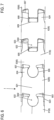
- the transition area from the bend section A to the flexible section 20 is in 2 indicated as region K.
- region K the angled section A ends.
- the wall surface of the tubular member is cut by a cut 70 in the shape of an inverted C letter.
- the cut 70 in the tubular member is cut in the shape of an incomplete circle.
- the circle of cut 70 is uncut on the distal side.
- the uncut distal side of the cut 70 forms a hinge 71 for a tab 72.
- the tab 72 has a lower ear 73, an upper ear 74, and a tab midpiece 75.
- On an upper side of the tab midpiece 75 is the lower ear 73 abutted.
- the upper ear 74 adjoins a lower side of the tab center piece 75 .
- the tab 72 is made as follows. The location of the cut 70 is determined. In the middle of the cut 70 a hole 77 is cut. The cut 70 is made by laser as in 2 shown formed.
- the link center piece 75 is supported from the rear, ie from the inside of the tubular element, by a stamp.
- the lower ear 73 is bent inwardly 90 degrees relative to the tab center 75 .
- the bending line of the ear 73 relative to the strap center piece 75 runs parallel to the axis of the tubular element (in figures 2 and 4 in the left and right direction).
- the upper ear 74 is also bent inwardly 90 degrees relative to the tab center 75 .
- the bend line of the ear 74 relative to the tab center piece 75 is also parallel to the axis of the tubular member.
- the tab center piece 75 is bent 90 degrees inward.
- the bending line of the tab center piece 75 relative to the tubular element runs in the perpendicular sectional plane to the axis of the tubular element (in figures 2 and 4 in the up and down direction).
- the tab center 75 at the hinge 71 is bent inward 90 degrees.
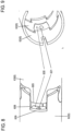
- the tab center piece 75 is bent inward until a distal side edge of the lower ear 73 and a distal side edge of the upper ear 74 abut the inner circumference of the tubular member, see FIG figure 5 ).
- the tab 72 serves as a support for a guide spring 8.
- the proximal surface of the tab center piece 75 forms a stop surface for the distal end of the guide spring 8.
- the two ears 73, 74 support the tab center piece 75 and absorb the compressive forces acting on the guide spring 8 and conduct them to the inner peripheral surface of the tubular member.
- the tab center piece 75 has the central hole 77.
- the hole 77 has a larger diameter than a control wire and a smaller diameter than the guide spring 8.
- the control wire is guided in the flexible section 20 in the guide spring 8 and passes through the hole 70 and extends further into into the bend section A.
- tabs 72 are provided in the number of control wires used (in the present embodiment: four). The tabs 72 are evenly distributed in the circumferential direction of the tube element.
- the bend section A has individual joint members 6 which are arranged in the longitudinal direction of the bend section A.
- the individual joints 6 are pivotable relative to each other.
- three joint members 6 arranged one behind the other are shown: a joint 61, a joint 62 proximal to joint 61 and a joint 63 proximal to joint 62.
- the articulation members 6 are identical to each other with the exception of the most distal articulation member 6 and the most proximal articulation member 6.
- the joint member 62 is formed as a tubular portion of said tubular member by laser cutting.
- the joint member 62 has distal boundary lines 601, 602, 603, 604 and 605 and proximal boundary lines 606, 607, 608 and 609 on the circumference of the tubular element.
- the individual distal boundary lines are composed of a head line 601 shaped like a circle, two neck lines 602, two shoulder lines 603, two arm lines 604 and an arm end line 605. More specifically, the distal side of the joint member 62 is formed as follows.
- the circular shaped head line 601 forms an incomplete circle merging into a neck line 602 on each side at the proximal side.
- Each of the two neck lines 602 is followed by a shoulder line 603 which runs approximately perpendicular to the axis of the tube element.
- Each of the two shoulder lines 603 is followed by an arm line 604 which runs approximately parallel to the axis of the tubular element in the distal direction.
- the two distal ends of the arm lines 604 are connected by an arm end line 605 which is again perpendicular to the axis of the tubular member.
- the articulated member 62 has a main body 621 from which, towards the distal side, a first head 622, a first arm 623, a second head 622 and a second arm 623 are each rotated by 90 degrees along an imaginary circumferential line perpendicular to the axis of the articulated member 62 runs, protrude.
- the heads 622, 622 extend in a first imaginary plane.
- the arms 623, 623 extend in a second imaginary plane which is offset by 90 degrees to the first imaginary plane.
- the two heads 622, 622 of the joint member 62 form a pivot axis for the joint member 61 located distally from them.
- Each head 622 is formed by a head line 601 on the distal side. A constriction is formed between the head 622 and the main body 621 by the neck lines 602 . Each head 622 protrudes further in the distal direction than each arm 623.
- the individual proximal boundary lines are composed of a curved root line 606, two bottom lines 607, two straight root lines 608 and a waist line 609. More specifically, the proximal side of the joint member 62 is formed as follows.
- the curved root line 606 forms an incomplete circle that is open on the proximal side. At the open ends of the incomplete circle, the curved root line 606 merges with the bottom line 607, which is approximately perpendicular to the axis of the tubular element.
- Each of the two bottom lines 607 is followed by a straight bottom line 608 which runs in the distal direction approximately parallel to the axis of the tube element.
- the two distal ends of the straight root lines 608 are connected by a waist line 609 which is again perpendicular to the axis of the tubular member.
- the joint member 62 has two feet 624 on the proximal side of the main body 621, which extend in the proximal direction.
- Each foot 624 has a spanwise straight side at straight foot line 608 and a curved side at curved foot line 606.
- an arm of the proximal link member 63 is arranged to be displaceable in the longitudinal direction.
- a head of the proximal link member 63 is held immovable in the longitudinal direction. At most a slight movement due to play between the inner circumference the curved base line and the outer circumference of the circular shaped head line is possible.
- the waist line 609 is spaced from the arm end line 605 of the proximal joint member 63, as shown in FIG 7 is shown.
- the arm end line 605 and the waist line 609 of the proximal joint member 63 are parallel to each other.
- the bottom line 607 is spaced from the shoulder line 603 of the proximal link member 63, as shown in FIG 7 is shown.
- the bottom line 607 and the shoulder line 603 of the proximally located link member 63 may be parallel to one another or approximately parallel to one another or slightly angled to one another as shown in FIG 7 is shown. Not only has a simple cut line been created between the bottom line 607 and the shoulder line 603 of the proximal hinge member 63, but the material of the tubular member has been cut out as a square piece.
- a respective head 622 forms a coupling portion which is coupled to an adjacent link member 6 .
- the feet 624 form a guide portion which engages an adjacent link 6 such that axial movement of the link 6 relative to each other is permitted.
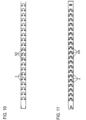
- FIG. 10 shows a plan view of the angled section A with the respective joint members 6.
- the heads 622 of the joint members 6 can be seen in the plan view.
- FIG. 11 shows a side view of the bending section A with the respective articulated members 6.
- the feet 624 of the articulated members 6 can be seen in the side view.
- the distal-most joint member 6 has no head and is in the figures 2 and 10 to 14 shown.
- the most proximal joint member 6 has no foot and is in the figures 2 , 4 and 11 shown.
- the bending section A can be bent in two directions, namely in the Figures 6 and 7 (and 10 ) up and down, with the respective heads 622 of the link members 6 forming bending axes of the link members 6.
- the bending section A in 10 pivotable up and down.
- the flexing portion A is pivotable toward and away from the viewer.
- the waistline 609 forms a hinge portion for a fairlead 630.
- the fairlead 630 extends from the waistline 609.
- a section of material is taken that extends along the straight footlines 608 to the arm end line 605 of the proximally located articulation member 63 .
- the fairlead 630 is hinged at the waist line 609 and is bent inward at 90 degrees.
- the cable guide lug 630 has a central hole 631.
- the hole 631 has a larger diameter than the control wire.
- Each of the joint members 6 has the wire guide tabs 630 with the hole 631 such that the wire guide tabs 630 for a specific control wire are arranged in a row in the longitudinal direction of the bend portion A.
- the cable guide tabs 630 serve as guide projections on which a control wire is supported.
- the cable guide tabs 630 guide the control wire assigned to them through the bend section A.
- the joint members 6 may be arranged at the bending portion A with their heads pointing in the proximal direction, as shown in FIG 10 is shown. Alternatively, the joint members 6 may be arranged at the bending portion A with their heads pointing in the distal direction, as shown in FIG 6 is indicated.
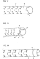
- the distal end of the bend section A is in the Figures 12 to 14 shown.
- the joint member 69 of the bend section A located furthest on the distal side can be seen.
- the distal side of the control wire 9 is anchored in this joint member 69 located furthest on the distal side.
- the control wire 9 extends from the control body 3 to the most distal-side joint member 69 of the bending section A.
- control wire 9 The exact attachment of the control wire 9 is in the Figures 15 and 16 shown.
- the control wire 9 is attached to the steering wheel G in the control body 3 .
- the steering wheel G is rotated in a tightening direction, the steering wire 9 is tightened.
- the control wheel G is rotated in the release direction opposite to the tensioning direction, the control wire 9 is released.
- the control wire 9 extends from the control body 3 in the insertion tube 2 to the articulated member 69 and forms a first section 91.
- This first section 91 of the control wire 9 runs along the inner circumference of the insertion tube 2.
- This first section 91 of the control wire 9 is identified by reference numeral 91 in 15 shown.
- a slit 691 penetrating the peripheral wall of the joint member 69 is formed (see Fig 13 ) extending in the longitudinal direction of the link member 69.
- Another similar slot 692 is provided on the distal side of link member 69 diametrically opposite slot 691 .
- the control wire 9 extends in the distal direction on the inner periphery of the joint member 69 and penetrates the slit 691 outward, is wound on the outer periphery of the joint member 69 in the circumferential direction of the joint member 69 up to the slit 692, penetrates the slit 692 inward, and extends at the Inner circumference of the joint member 69 in the proximal direction up to the steering wheel G in the control body 3.
- the control wire 9 is thus divided into a first section 91, which extends from the steering wheel G in the control body 3 to the slot 691, and a second section 92, which extends from the slot 691 on the outer circumference of the joint member 69 in the circumferential direction of the joint member 69 to the slot 692 , and a third portion 93 extending from the slot 692 to the steering wheel G in the control body 3.
- control wire 9 By rotating the control wheel G in the tensioning direction, the control wire 9 is tensioned and the angled section A is thus angled, since the third section 93 anchored on the joint member 69 is pushed in the proximal direction.
- the third section 93 of the control wire 9 thus forms a distal anchoring section of the control wire 9.
- the insertion tube 2 according to the invention is made from a single tubular element which is cut by laser.
- the tube element is made of a relatively hard material such as stainless steel or even a suitable hard plastic.
- the initially hard tubular element becomes flexible due to the cuts, but retains its rigidity.
- the cuts create the respective lateral incisions S in the proximal passive flexible section 20, the hole 77, the cut 70 in the transition region K, the hole 631, the respective articulation members 6 in the distal bending section A and the slits 691, 692.
- This order is not as understand limitation.
- the slits 691, 692 can be cut in front of the link members 6. The order of the cuts can also be reversed.
- the flexibility and also the rigidity of the tubular element can be controlled by means of the shape, the arrangement and the size of the cuts.
- the location of the respective cuts can be calculated and predetermined beforehand.
- the specified Data for the respective cuts are entered in order to generate the insertion tube 2 automatically.
- the individual joint members 6 are completely cut out and form bodies that are physically separate from one another and are only connected in a form-fitting manner.
- the tabs 72 and the wire guide tabs 630 are bent inward. Thus, the raw body for the insertion tube 2 is completed.
- the control wire 9 can now be inserted and fastened in this raw body for the insertion tube 2 .
- the raw body for the insertion tube 2 can be attached to the control body 3 .
- a coating of preferably metal surrounding the raw body for the insertion tube 2 for shielding the electrical control system can be pulled onto the raw body for the insertion tube 2 and an elastic jacket made of plastic or rubber can be pulled over this.
- the elastic sheath made of plastic or rubber can be subjected to thermal shrinkage.
- the individual joints in the bending section are formed by means of cuts in such a way that they have projections and depressions in the extension direction of the endoscope.
- the projections seat in the indentations of the adjacent joint to allow pivotal movement of the joint.
- the individual joints are connected in a form-fitting manner.
- the bending portion A' is provided with a plurality of cuts 801, 802 made perpendicular to the axis of the bending portion A'. More specifically, the cuts 801, 802 are made such that a cut 801 is made from above through the tubular member perpendicular to the axis of the tubular member to a depth terminating in front of the central axis region. Also, a cut 802 is made from below through the tubular member perpendicular to the axis of the tubular member to a depth also terminating forward of the central axis region.
- the cuts 801 and 802 are coplanar and their ends face each other across a space 803 left.
- the space 803 is an uncut space in the central axis portion of the pipe member.
- the cuts 801 are parallel to each other.
- the cuts 802 are also parallel to one another in an analogous manner.
- the straight cuts 801, 802 function as a hinge and allow the bending movement of the bending portion A'.
- a predefined number of cuts 801 (and of course analogous to 802) lying one behind the other in the longitudinal direction of the bending section A' are combined to form a group.
- cuts 801 each belong to a group, with the number of cuts 801, 802 per group being able to be chosen as suitably as desired.
- the respective group of cuts 801, 802 is delimited in the longitudinal direction of the bending section A' by a ring section 805 with short cuts 811, 812.
- the short cuts 811, 812 are made so that a short cut 811 is made from above through the tubular element perpendicularly in the direction of the axis of the tubular element to a very short depth, as shown in FIG 17 shown is.
- This short depth can be, for example, one tenth to one twentieth of the diameter of the tubular element.
- the length of the short cuts 811, 812 can be selected as appropriate.
- each short cut 812 is made from below in a similar manner to the short cuts 811 from above.
- the cuts 811 are parallel to each other.
- the cuts 812 are also parallel to one another in an analogous manner.
- the short cuts 811 and 812 each form a pair and each lie on a plane and their ends face each other across a left space forming the ring portion 805 .
- the ring portion 805 is a portion of the tubular member that has only a pair of short cuts 811,812.
- the material of the tubular element which is adjacent to the respective short cuts 811, 812 forms a band section.
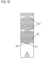
- This band section forms a cable guide tab 880 when bent toward the tube center of the tube member, as shown in FIG 19 is shown.
- a traction cable can thus be guided in the gap formed between the outwardly facing surface of the band portion of the cable guide tab 880 and the longitudinally adjacent inner peripheral surface of the tubular member.
- the straight cuts 801, 802 can be provided at the bending portion A' so that the rigidity is similar to that in the first embodiment.
- the flexible section 20 has a first zone B, a second zone C and a third zone D with different flexibility when viewed in the proximal direction.
- the number of zones or areas with different flexibility is not limited.
- the flexible section 20 can also have more or fewer zones with different flexibility.
- the invention is also applicable to an insertion tube in which the flexible portion 20 has constant flexibility throughout.
- the tubular element of the insertion tube 2 is made of stainless steel.
- the material of the insertion tube 2 can be any sufficiently rigid material, such as a rigid plastic.
- Nitinol a nickel-titanium alloy
- this material has the property of so-called superelasticity, i.e. it can be elastically deformed over a wide range without becoming permanently bent.
- cuts are provided in the tube element by a laser cutting machine. These cuts can be provided very precisely. Therefore, manufacturing by laser is preferred. In principle, however, it is conceivable that these cuts can also be made using other manufacturing processes such as saws, wire saws, etc.
- the bending section A can be bent in two directions, namely in the Figures 6 and 7 up and down.
- the individual joint members 6 can be designed such that their heads 622 are offset from joint member 6 to joint member 6 rotated by 90 degrees about the axis of the bending section A (axis of the joint members 6).
- the bend section A can be bent in four bend directions, namely in the Figures 6 and 7 up and down and towards and away from the viewer.
- two control wires 9 can be used, which run in the insertion tube 2 offset by 90 degrees to one another.
- the Link 92 is then provided with four distal slots which are also offset 90 degrees from one another.
- a respective joint member 6 is designed in the form described.
- the invention is not limited to the shape of the joint member 6. It is sufficient if articulated links are cut in the angled section A, which are coupled to one another and allow a deflection movement of the angled section A.
- the invention can advantageously be used with a duodenoscope, a gastroscope, a colonoscope or a similar endoscope.
- the principle of the invention can also be applied to any other type of endoscope.
- the principle of the invention is also applicable to other medical devices using an insertion tube.
Description
Die vorliegende Erfindung bezieht sich auf ein Verfahren zur Herstellung eines Einführschlauches eines Endoskops und auf ein Endoskop mit einem Einführschlauch.The present invention relates to a method for manufacturing an insertion tube of an endoscope and to an endoscope with an insertion tube.
Ein Endoskop ist ein Gerät, mit dem das Innere von lebenden Organismen, aber auch technischen Hohlräumen untersucht werden kann. Ein wichtiges Teil eines Endoskops ist der flexible Einführschlauch. Die Anforderungen an einen Einführschlauch sind hoch und vielseitig. Einerseits muss er flexibel sein, um in den menschlichen Körper eingeführt werden zu können. Andererseits muss der Einführschlauch bestimmte Steifigkeit besitzen. Bei der Untersuchung muss der Arzt den Einführschlauch anhand des Kontrollkörpers schieben und drehen können. Dabei muss der Einführschlauch so steif sein, dass er nicht geknickt bzw. verdreht wird. Herkömmliche Einführschläuche bedingen daher eine sehr komplexe Aufbauweise und hohe Herstellungskosten, um die genannten Anforderungen zu erfüllen.An endoscope is a device that can be used to examine the inside of living organisms, but also technical cavities. An important part of an endoscope is the flexible insertion tube. The demands on an insertion tube are high and diverse. On the one hand, it must be flexible in order to be able to be inserted into the human body. On the other hand, the insertion tube must have a certain rigidity. During the examination, the doctor must be able to push and turn the insertion tube using the control body. The insertion tube must be so stiff that it is not kinked or twisted. Conventional insertion tubes therefore require a very complex structure and high manufacturing costs in order to meet the requirements mentioned.
Um die Herstellung eines Schlauchelementes für medizinische Zwecke zu vereinfachen und die Herstellkosten zu senken, ist im Stand der Technik die Idee entstanden, ein Schlauchelement für medizinische Zwecke aus einem einzigen harten Rohr herzustellen. Mit einer Laserschneidmaschine werden an dem harten Rohr verschiedene hochpräzise Schnitte erzeugt. Durch die Schnitte wird ein hartes Rohr flexibel, kann aber die Steifigkeit behalten. Die Flexibilität bzw. Steifigkeit des Rohrs kann anhand der Form, der Anordnung und der Größe der Schnitte gesteuert werden.In order to simplify the production of a hose element for medical purposes and to reduce the production costs, the prior art has come up with the idea of producing a hose element for medical purposes from a single hard tube. Various high-precision cuts are made on the hard tube with a laser cutting machine. The cuts make a hard tube flexible but able to retain rigidity. The flexibility or stiffness of the tube can be controlled by the shape, placement and size of the cuts.
Die
Die
Es ist die Aufgabe der vorliegenden Erfindung, ein Verfahren zur Herstellung eines Einführschlauches eines Endoskops und ein Endoskop mit einem Einführschlauch zu schaffen, die weniger komplex sind und durch die die Kosten noch weiter gesenkt werden können.It is the object of the present invention to provide a method for manufacturing an insertion tube of an endoscope and an endoscope with an insertion tube, which are less complex and by which costs can be further reduced.
In Hinblick auf das Verfahren ist die Aufgabe durch ein Verfahren mit den Merkmalen von Anspruch 1 gelöst. Ein Endoskop mit einem Einführschlauch ist in Anspruch 8 aufgezeigt. Vorteilhafte Weiterbildungen sind Gegenstand der abhängigen Ansprüche.With regard to the method, the object is achieved by a method having the features of claim 1. An endoscope with an insertion tube is set out in
-
Fig. 1 zeigt eine schematische Seitenansicht eines Endoskops.1 shows a schematic side view of an endoscope. -
Fig. 2 zeigt eine ausschnittartige schematische Ansicht eines Einführschlauches.2 shows a partial schematic view of an insertion tube. -
Fig. 3 zeigt eine ausschnittartige schematische Ansicht eines Teils eines proximalen passiven flexiblen Abschnittes des Einführschlauches,3 shows a partial schematic view of part of a proximal passive flexible section of the insertion tube, -
Fig. 4 zeigt eine ausschnittartige schematische Ansicht eines Übergangsbereiches zwischen dem distalen Abwinkelungsabschnitt und dem proximalen passiven flexiblen Abschnitt des Einführschlauches, wobei ein Führungsfederfixierabschnitt gezeigt ist.4 FIG. 12 shows a partial schematic view of a transition area between the distal bend section and the proximal passive flexible section of the insertion tube, showing a guide spring fixing section. -
Fig. 5 zeigt eine ausschnittartige perspektivische Ansicht des Führungsfederfixierabschnittes ausFig. 4 von einer anderen Seite.figure 5 FIG. 14 is a partial perspective view of the guide spring fixing portion4 from another side. -
Fig. 6 zeigt eine ausschnittartige schematische Ansicht eines Teils des Abwinkelungsabschnittes des Einführschlauches,6 shows a fragmentary schematic view of part of the angled section of the insertion tube, -
Fig. 7 zeigt eine ausschnittartige schematische Ansicht des Teils des Abwinkelungsabschnittes des Einführschlauches, wobei eine Ansicht aus der Richtung eines Pfeiles I ausFig. 6 gezeigt ist.7 Fig. 13 is a fragmentary schematic view of part of the bend portion of the insertion tube, which is a view from the direction of an arrow I. Figs6 is shown. -
Fig. 8 zeigt eine ausschnittartige schematische Ansicht eines Teils des Abwinkelungsabschnittes des Einführschlauches, wobei eine Seilführung gezeigt ist.8 Figure 13 is a fragmentary schematic view of a portion of the bend portion of the insertion tube showing a cable guide. -
Fig. 9 zeigt eine ausschnittartige perspektivische Ansicht der Seilführung ausFig. 7 .9 shows a fragmentary perspective view of thecable guide 7 . -
Fig. 10 zeigt eine ausschnittartige schematische Seitenansicht des Abwinkelungsabschnittes des Einführschlauches,10 shows a fragmentary schematic side view of the angled section of the insertion tube, -
Fig. 11 zeigt eine ausschnittartige schematische Draufsicht des Abwinkelungsabschnittes vonFig. 10 .11 shows a detail-like schematic top view of the bending section of FIG10 . -
Die
Figuren 12 bis 14 zeigen jeweils eine ausschnittartige perspektivische Ansicht des distalen Endes des Abwinkelungsabschnittes.TheFigures 12 to 14 each show a fragmentary perspective view of the distal end of the bend section. -
Fig. 15 zeigt eine ausschnittartige perspektivische Ansicht der Zugseilverankerung am distalen Ende des Abwinkelungsabschnittes.15 shows a fragmentary perspective view of the traction cable anchorage at the distal end of the angled section. -
Fig. 16 zeigt eineFig. 15 entsprechende Ansicht von einer anderen Seite.16 shows one15 corresponding view from another side. -
Fig. 17 zeigt einen Biegeabschnitt eines erfindungsgemässen Ausführungsbeispiels in einer Seitenansicht.17 shows a bending section of an embodiment according to the invention in a side view. -
Fig. 18 zeigt eine Draufsicht auf einen distalen Bereich des Biegeabschnittes des erfindungsgemässen Ausführungsbeispiels.18 shows a plan view of a distal area of the bending section of the embodiment according to the invention. -
Fig. 19 zeigt eine Querschnittsansicht des Biegeabschnittes des erfindungsgemässen Ausführungsbeispiels.19 Fig. 12 shows a cross-sectional view of the bending portion of the embodiment of the present invention.
Nachstehend ist die vorliegende Erfindung detailliert unter Bezugnahme auf die Zeichnungen anhand von Ausführungsbeispielen beschrieben.The present invention is described in detail below with reference to the drawings using exemplary embodiments.
Nachstehend ist unter Bezugnahme auf die
Zunächst
Der Einführschlauch 2 ist ein zylindrisches rohr- oder schlauchartiges Gebilde. Nachstehend ist der Einführschlauch 2 detaillierter in der Richtung, in der er bei einem Patienten eingeschoben wird, beschrieben. Der Einführschlauch 2 wird mit dem distalen Ende voran eingeschoben.The
An der distalen Seite besitzt der Einführschlauch 2 einen distalen Abwinkelungsabschnitt A. Der Abwinkelungsabschnitt A kann mittels einem oder mehreren Steuerdrähten (Seilzug oder Seilzüge) relativ zum proximalen Teil des Einführschlauches 2 seitlich abgewinkelt werden. Der Steuerdraht oder Seilzug (nachfolgend nur als Steuerdraht bezeichnet) ist im Inneren des Einführschlauches 2 an einer Innenumfangsfläche des Einführschlauches 2 in Erstreckungsrichtung des Einführschlauches 2 geführt gelagert.On the distal side, the
Das distale Ende des Steuerdrahts ist an der distalen Seite des Abwinkelungsabschnittes A verankert. Das proximale Ende des Steuerdrahts ist mit einem im Kontrollkörper 3 angeordneten Steuerelement verbunden. Dieses Steuerelement spannt den Steuerdraht, um eine erwünschte Abwinkelung des Abwinkelungsabschnittes A zu bewerkstelligen.The distal end of the control wire is anchored to the distal side of the bend section A. The proximal end of the control wire is connected to a control element arranged in the
Proximal vom Abwinkelungsabschnitt A ist der Einführschlauch 2 als ein flexibles Schlauchelement gestaltet, das einen proximalen passiven flexiblen Abschnitt 20 ausbildet. Beim Einschieben des Einführschlauches 2 folgt der flexible Abschnitt 20 dem Abwinkelungsabschnitt A.Proximal to the bend section A, the
In
In der ausschnittartigen Darstellung von
Zur Vermeidung einer Knickbiegung zwischen dem Abwinkelungsabschnitt A und der ersten Zone B ist die erste Zone B vorzugsweise mit der höchsten Flexibilität unter den Zonen des flexiblen Abschnittes 20 versehen. Da die erste Zone B mit einer sehr hohen Flexibilität ausgestattet ist, ergibt sich kein abrupter Übergang der Flexibilität zwischen dem Abwinkelungsabschnitt A und der ersten Zone B.In order to avoid a buckling bend between the bending section A and the first zone B, the first zone B is preferably provided with the highest flexibility among the zones of the
Die zweite Zone C hat eine geringere Flexibilität als die erste Zone B. Die dritte Zone D hat eine wiederum geringere Flexibilität als die zweite Zone C.The second zone C has less flexibility than the first zone B. The third zone D, in turn, has less flexibility than the second zone C.
Der erfindungsgemäße Einführschlauch 2 ist aus einem Stück gebildet. Das heißt, am Übergang vom Abwinkelungsabschnitt A zum flexiblen Abschnitt 20 sind nicht zwei Elemente zusammengefügt. Somit sind der distale Abwinkelungsabschnitt A und der proximale passive flexiblen Abschnitt 20 mit den drei Zonen A, B und C aus einem einzigen Rohr oder Schlauch gebildet.The
An der proximalen Seite ist der Einführschlauch 2 am distalen Ende des Kontrollkörpers 3 fixiert. Der Einführschlauch 2 kann am Kontrollkörper 3 z.B. durch einen Feststellring, einen Dichtungsring oder direkt fixiert sein. Der Einführschlauch 2 kann am Kontrollkörper 3 z.B. angeklebt oder angeschraubt sein. Der Kontrollkörper 3 hat ein erstes Steuerrad F als ein erstes Steuerelement zum Steuern eines Steuerdrahtes oder Seilzugs und ein zweites Steuerrad G als ein zweites Steuerelement zum Steuern eines Steuerdrahtes oder Seilzugs. Das erste Steuerrad F kann durch Ziehen eines Steuerdrahtes oder Seilzugs den Abwinkelungsabschnitt A in einer ersten Ebene abwinkeln (z.B. zum Betrachter hin und vom Betrachter weg in
Der Abwinkelungsabschnitt A kann z.B. um 200 - 270 Grad abgewinkelt werden. Dies ist für die meisten Anwendungen ausreichend. In einer Spezialform kann der Abwinkelungsabschnitt A sogar um 300 Grad abgewinkelt werden.The angling section A can be angled by 200 - 270 degrees, for example. This is sufficient for most applications. In a special form, the angled section A can even be angled by 300 degrees.
Nachstehend ist der erfindungsgemäße Einführschlauch 2 und seine Herstellung detaillierter beschrieben.The
Der gesamte Einführschlauch 2 ist aus einem einzigen Rohrelement oder Schlauchelement (nachstehend ist dieses einfach als Rohrelement bezeichnet) gebildet. Das Rohrelement ist ein Rohr aus vorzugsweise relativ hartem Material. Besonders bevorzugt ist ein Rohr aus Edelstahl. Es kann aber auch ein Rohr aus hartem Kunststoff angewendet werden. Im Prinzip kann aber jedes für medizinische Zwecke anwendbare Material genutzt werden.The
Durch eine Laserschneidmaschine werden im Rohrelement Schnitte vorgesehen, wie dies nachstehend detaillierter erläutert ist. Nach dem Vorsehen der Schnitte werden bestimmte Teilabschnitte des Rohrelementes gebogen, wie dies nachstehend detaillierter erläutert ist. Die Herstellung des Grundkörpers des gesamten Einführschlauches 2 macht keine weiteren Verfahrensschritte außer dem Vorsehen von Schnitten und dem Biegen erforderlich. Danach kann der Grundkörper des Einführschlauches 2 mit einem Steuerdraht versehen werden und einem Mantelelement ummantelt werden.Cuts are provided in the tubular member by a laser cutting machine, as discussed in more detail below. After the cuts have been made, certain sections of the tubular member are bent, as will be explained in more detail below. The production of the main body of the
Nachstehend sind die einzelnen Abschnitte des Einführschlauches 2 genauer beschrieben.The individual sections of the
Der flexible Abschnitt 20 bildet den proximalen Teil des erfindungsgemäßen Einführschlauches 2. Der flexible Abschnitt 20 hat die drei Zonen B, C und D mit jeweils unterschiedlicher Flexibilität.The
Der flexible Abschnitt 20 ist mit einer Vielzahl an Schnitten S versehen, die senkrecht zur Achse des flexiblen Abschnittes 20 ausgeführt sind. Genauer gesagt sind die Schnitte S so ausgeführt, dass ein Schnitt 201 von oben durch das Rohrelement senkrecht zur Achse des Rohrelements bis zu einer Tiefe erfolgt, die vor dem Mittelachsenbereich endet. Ferner erfolgt ein Schnitt 202 von unten durch das Rohrelement senkrecht zur Achse des Rohrelements bis zu einer Tiefe, die ebenfalls vor dem Mittelachsenbereich endet. Die Schnitte 201 und 202 liegen auf einer Ebene und ihre Enden stehen einander über einen belassenen Zwischenraum 203 gegenüber. Der Zwischenraum 203 ist ein nicht geschnittener Zwischenraum im Mittelachsenbereich des Rohrelements.The
Darüber hinaus erfolgt ähnlich wie bei den Schnitten 201 und 202 ein Schnitt 204 von einer (z.B. linken) Seite (der Schnitt 204 zeigt einen Schnitt von der Seite des Betrachters) durch das Rohrelement senkrecht zur Achse des Rohrelements bis zu einer Tiefe, die vor dem Mittelachsenbereich endet. Ferner erfolgt ein Schnitt von der entgegengesetzten (z.B. rechten) Seite (dieser Schnitt ist in
Der Zwischenraum 203 zwischen den Schnitten 201 und 202 und der Zwischenraum zwischen Schnitt 204 und seinem zugehörigen Schnitt der entgegengesetzten Seite sind um 90 Grad entlang der Umfangsrichtung des Rohrelements versetzt.The
Die Schnitte 201 und 202 und die Schnitte 204 und sein zugehöriger Schnitt der entgegengesetzten Seite sind benachbart zueinander und wechseln einander über die Länge der jeweiligen Zone im flexiblen Abschnitt 20 ab, siehe
Somit ist der flexiblen Abschnitt 20 lateral zu seiner Längsachse um die Zwischenräume biegbar.Thus, the
Die einzelnen Zonen B, C und D unterscheiden sich dadurch, dass die Abstände der Schnitte S in Längsrichtung und somit die Dichte der Schnitte S unterschiedlich gestaltet sind.The individual zones B, C and D differ in that the distances between the cuts S in the longitudinal direction and thus the density of the cuts S are designed differently.
In der Zone B ist der Abstand der Schnitte S am geringsten. Somit ist in der Zone B die Dichte der Schnitte S am höchsten.In zone B, the distance between the cuts S is the smallest. Thus, in zone B, the density of cuts S is highest.
In der Zone C ist der Abstand der Schnitte S größer als in der Zone B. In der Zone D ist der Abstand der Schnitte S größer als in der Zone C.In zone C, the distance between the cuts S is greater than in zone B. In zone D, the distance between the cuts S is greater than in zone C.
Somit ist die Flexibilität und die Biegbarkeit in der Zone B höher als in der Zone C. Ferner ist die Flexibilität und die Biegbarkeit in der Zone C höher als in der Zone D. Anders ausgedrückt nehmen die Flexibilität und die Biegbarkeit der jeweiligen Zonen am flexiblen Abschnitt 20 in proximaler Richtung ab.Thus, the flexibility and bendability in zone B is higher than in zone C. Furthermore, the flexibility and bendability in zone C is higher than in zone C Zone D. In other words, the flexibility and the bendability of the respective zones on the
Die Zone D ist an der proximalen Seite mit einem Bereich versehen, der nicht mit Schnitten versehen ist. Dieser Bereich bildet einen Übergang zum Kontrollkörper J.Zone D is provided with an area on the proximal side that is not provided with cuts. This area forms a transition to the control body J.
Der Übergangsbereich vom Abwinkelungsabschnitt A zum flexiblen Abschnitt 20 ist in
Wie in
Die Lasche 72 wird wie folgt hergestellt. Der Ort des Schnittes 70 wird festgelegt. In der Mitte des Schnittes 70 wird ein Loch 77 geschnitten. Der Schnitt 70 wird per Laser wie in
Die Lasche 72 dient als Abstützung einer Führungsfeder 8. Insbesondere bildet die proximale Fläche des Laschenmittelstücks 75 eine Anschlagfläche für das distale Ende der Führungsfeder 8. Die beiden Ohren 73, 74 stützen das Laschenmittelstück 75 und nehmen von der Führungsfeder 8 wirkende Drückkräfte auf und leiten diese an die Innenumfangsfläche des Rohrelements weiter.The
Das Laschenmittelstück 75 besitzt das zentrische Loch 77. Das Loch 77 hat einen größeren Durchmesser als ein Steuerdraht und einen kleineren Durchmesser als die Führungsfeder 8. Der Steuerdraht wird im flexiblen Abschnitt 20 in der Führungsfeder 8 geführt und durchläuft das Loch 70 und erstreckt sich weiter in den Abwinkelungsabschnitt A hinein.The
Im Bereich K sind Laschen 72 in der Anzahl der verwendeten Steuerdrähte (im vorliegenden Ausführungsbeispiel: vier) vorgesehen. Die Laschen 72 sind in Umfangsrichtung des Rohrelements gleichmäßig verteilt.In the
Der genauere Aufbau des Abwinkelungsabschnittes A ist in den
Der Abwinkelungsabschnitt A hat einzelne Gelenkglieder 6, die in Längsrichtung des Abwinkelungsabschnittes A angeordnet sind. Die einzelnen Gelenkglieder 6 sind relativ zueinander schwenkbar. In den
Die Gelenkglieder 6 sind zueinander gleich gestaltet mit Ausnahme des am weitesten distal befindlichen Gelenkglieds 6 und des am weitesten proximal befindlichen Gelenkglieds 6.The
Der Aufbau des jeweiligen Gelenkglieds 6 ist nachstehend anhand Gelenkglied 62 erörtert.The construction of the respective articulated
Das Gelenkglied 62 ist als ein Rohrabschnitt des genannten Rohrelements durch Laserschneiden ausgebildet. Das Gelenkglied 62 besitzt am Umfang des Rohrelements distale Begrenzungslinien 601, 602, 603, 604 und 605 und proximale Begrenzungslinien 606, 607, 608 und 609.The
Die einzelnen distalen Begrenzungslinien setzen sich zusammen aus einer kreisartig geformten Kopflinie 601, zwei Halslinien 602, zwei Schulterlinien 603, zwei Armlinien 604 und einer Armendlinie 605. Genauer gesagt ist die distale Seite des Gelenkglieds 62 folgendermaßen gebildet. Die kreisartig geformte Kopflinie 601 bildet einen unvollständigen Kreis, der an der proximalen Seite an jeder Seite in eine Halslinie 602 übergeht. An jeder der beiden Halslinien 602 schließt sich eine Schulterlinie 603 an, die annähernd senkrecht zur Achse des Rohrelements verläuft. An jeder der beiden Schulterlinien 603 schließt sich eine Armlinie 604 an, die annähernd parallel zur Achse des Rohrelements in die distale Richtung verläuft. Die beiden distalen Enden der Armlinien 604 sind durch eine Armendlinie 605 verbunden, die wieder senkrecht zur Achse des Rohrelements verläuft.The individual distal boundary lines are composed of a head line 601 shaped like a circle, two
Dadurch hat das Gelenkglied 62 einen Hauptkörper 621, von dem zur distalen Seite hin ein erster Kopf 622, ein erster Arm 623, ein zweiter Kopf 622 und ein zweiter Arm 623 jeweils um 90 Grad entlang einer gedachten Umfangslinie, die senkrecht zur Achse des Gelenkglieds 62 verläuft, vorragen. Somit erstrecken sich die Köpfe 622, 622 in einer ersten gedachten Ebene. Die Arme 623, 623 erstrecken sich in einer zweiten gedachten Ebene, die um 90 Grad versetzt zur ersten gedachten Ebene ist. Die beiden Köpfe 622, 622 des Gelenkgliedes 62 bilden eine Schwenkachse für das distal von ihnen befindliche Gelenkglied 61.As a result, the articulated
Jeder Kopf 622 ist an der distalen Seite durch eine Kopflinie 601 gebildet. Zwischen dem Kopf 622 und dem Hauptkörper 621 ist eine Verengung durch die Halslinien 602 gebildet. Der jeweilige Kopf 622 ragt weiter in der distalen Richtung vor als der jeweilige Arm 623.Each
Die einzelnen proximalen Begrenzungslinien setzen sich zusammen aus einer gebogenen Fußlinie 606, zwei Bodenlinien 607, zwei geraden Fußlinien 608 und einer Bauchlinie 609. Genauer gesagt ist die proximale Seite des Gelenkglieds 62 folgendermaßen gebildet. Die gebogene Fußlinie 606 bildet einen unvollständigen Kreis, der an der proximalen Seite offen ist. An den offenen Enden des unvollständigen Kreises geht die gebogene Fußlinie 606 jeweils in die Bodenlinie 607 über, die jeweils annähernd senkrecht zur Achse des Rohrelements verläuft.The individual proximal boundary lines are composed of a
An jeder der beiden Bodenlinien 607 schließt sich eine gerade Fußlinie 608 an, die annähernd parallel zur Achse des Rohrelements in die distale Richtung verläuft. Die beiden distalen Enden der geraden Fußlinien 608 sind durch eine Bauchlinie 609 verbunden, die wieder senkrecht zur Achse des Rohrelements verläuft.Each of the two
Dadurch hat das Gelenkglied 62 an der proximalen Seite des Hauptkörpers 621 zwei Füsse 624, die sich in proximaler Richtung erstrecken. Jeder Fuß 624 hat in Erstreckungsrichtung eine gerade Seite an der geraden Fußlinie 608 und eine gekrümmte Seite an der gebogenen Fußlinie 606.As a result, the
In dem Bereich zwischen den beiden geraden Fußlinien 608 ist ein Arm des proximal befindlichen Gelenkgliedes 63 in Längsrichtung verschiebbar angeordnet. In dem Bereich zwischen den beiden gebogenen Fußlinien 606 wird ein Kopf des proximal befindlichen Gelenkgliedes 63 in Längsrichtung unbeweglich gehalten. Allelfalls eine geringfügige Bewegung aufgrund eines Spieles zwischen dem Innenumfang der gebogenen Fußlinie und dem Außenumfang der kreisartig geformten Kopflinie ist möglich.In the area between the two
Im nicht gebogenen Zustand des Abwinkelungsabschnittes A ist die Bauchlinie 609 von der Armendlinie 605 des proximal befindlichen Gelenkgliedes 63 beabstandet, wie dies in
Im nicht gebogenen Zustand des Abwinkelungsabschnittes A ist die Bodenlinie 607 von der Schulterlinie 603 des proximal befindlichen Gelenkgliedes 63 beabstandet, wie dies in
Ein jeweiliger Kopf 622 bildet einen Kupplungsabschnitt, der mit einem benachbarten Gelenkglied 6 gekuppelt ist. Die Füße 624 bilden einen Führungsabschnitt, der mit einem benachbarten Gelenkglied 6so in Eingriff steht, dass eine axiale Bewegung der Gelenkglieder 6 zueinander ermöglicht ist.A
Das am weitesten distal befindliche Gelenkglied 6 hat keinen Kopf und ist in den
Das am weitesten proximal befindliche Gelenkglied 6 hat keinen Fuß und ist in den
Im Ausführungsbeispiel kann der Abwinkelungsabschnitt A in zwei Abwinkelungsrichtungen abgewinkelt werden, nämlich in den
Wie dies in den
Jedes der Gelenkglieder 6 besitzt die Seilführungslaschen 630 mit dem Loch 631 so, dass die Seilführungslaschen 630 für einen spezifischen Steuerdraht in Längsrichtung des Abwinkelungsabschnittes A hintereinander angeordnet sind. Die Seilführungslaschen 630 dienen als Führungsvorsprünge, an denen ein Steuerdraht abgestützt ist Somit führen die Seilführungslaschen 630 den ihnen zugewiesenen Steuerdraht durch den Abwinkelungsabschnitt A.Each of the
Die Gelenkglieder 6 können am Abwinkelungsabschnitt A so angeordnet sein, dass ihre Köpfe in die proximale Richtung weisen, wie dies in
Das distale Ende des Abwinkelungsabschnittes A ist in den
Die genaue Befestigung des Steuerdrahtes 9 ist in den
Der Steuerdraht 9 ist im Kontrollkörper 3 am Steuerrad G befestigt. Wenn das Steuerrad G in eine Spannrichtung gedreht wird, wird der Steuerdraht 9 gespannt. Wenn das Steuerrad G in die zur Spannrichtung entgegengesetzte Entlasungsrichtung gedreht wird, wird der Steuerdraht 9 entlastet.The
Der Steuerdraht 9 erstreckt sich vom Kontrollkörper 3 kommend im Einführschlauch 2 verlaufend bis zum Gelenkglied 69 und bildet einen ersten Abschnitt 91. Dieser erste Abschnitt 91 des Steuerdrahtes 9 läuft am Innenumfang des Einführschlauches 2 entlang. Dieser erste Abschnitt 91 des Steuerdrahtes 9 ist anhand Bezugszeichen 91 in
Der Steuerdraht 9 erstreckt sich am Innenumfang des Gelenkgliedes 69 in die distale Richtung und durchdringt den Schlitz 691 nach außen, ist am Außenumfang des Gelenkgliedes 69 in Umfangsrichtung des Gelenkgliedes 69 bis zum Schlitz 692 gewunden, durchdringt den Schlitz 692 nach innen, und erstreckt sich am Innenumfang des Gelenkgliedes 69 in die proximale Richtung bis hin zum Steuerrad G im Kontrollkörper 3.The
Der Steuerdraht 9 ist somit in einen ersten Abschnitt 91, der sich vom Steuerrad G im Kontrollkörper 3 bis zum Schlitz 691 erstreckt, einen zweiten Abschnitt 92, der sich vom Schlitz 691 am Außenumfang des Gelenkgliedes 69 in Umfangsrichtung des Gelenkgliedes 69 bis zum Schlitz 692 erstreckt, und einen dritten Abschnitt 93 geteilt, der sich vom Schlitz 692 bis zum Steuerrad G im Kontrollkörper 3 erstreckt.The
Durch Drehen des Steuerrades G in die Spannrichtung wird der Steuerdraht 9 gespannt und somit der Abwinkelungsabschnitt A abgewinkelt, da der am Gelenkglied 69 verankerte dritte Abschnitt 93 in die proximale Richtung gedrängt wird. Der dritte Abschnitt 93 des Steuerdrahtes 9 bildet somit einen distalen Verankerungsabschnitt des Steuerdrahtes 9.By rotating the control wheel G in the tensioning direction, the
Der erfindungsgemäße Einführschlauch 2 wird durch ein einziges Rohrelement hergestellt, das per Laser geschnitten wird. Das Rohrelement ist aus einem relativ harten Material, wie z.B. Edelstahl oder auch geeigneter harter Kunststoff hergestellt. Durch die Schnitte wird das zunächst harte Rohrelement flexibel, behält aber seine Steifigkeit.The
Die Schnitte erzeugen die jeweiligen seitlichen Einschnitte S im proximalen passiven flexiblen Abschnitt 20, das Loch 77, den Schnitt 70 im Übergangsbereich K, das Loch 631, die jeweiligen Gelenkglieder 6 im distalen Abwinkelungsabschnitt A und die Schlitze 691, 692. Diese Reihenfolge ist nicht als Einschränkung aufzufassen. Z.B. können die Schlitze 691, 692 vor den Gelenkgliedern 6 geschnitten werden. Außerdem kann die Reihenfolge der Schnitte auch umgekehrt werden.The cuts create the respective lateral incisions S in the proximal passive
Die Flexibilität und auch die Steifigkeit des Rohrelementes können anhand der Form, der Anordnung und der Größe der Schnitte gesteuert werden.The flexibility and also the rigidity of the tubular element can be controlled by means of the shape, the arrangement and the size of the cuts.
Der Ort der jeweiligen Schnitte kann zuvor berechnet und vorbestimmt werden. In einer programmierbaren Laserschneidmaschine können die vorgegebenen Daten für die jeweiligen Schnitte eingegeben werden, um den Einführschlauch 2 automatisch zu erzeugen.The location of the respective cuts can be calculated and predetermined beforehand. In a programmable laser cutting machine, the specified Data for the respective cuts are entered in order to generate the
Die einzelnen Gelenkglieder 6 werden vollständig ausgeschnitten und bilden voneinander körperlich getrennte Körper, die lediglich formschlüssig verbunden sind.The individual
Nach dem Laserschneiden des Rohrelementes werden die Laschen 72 und die Seilführungslaschen 630 nach innen gebogen. Somit ist der Rohkörper für den Einführschlauch 2 fertiggestellt.After the tubular member has been laser cut, the
In diesem Rohkörper für den Einführschlauch 2 kann nun der Steuerdraht 9 eingeführt und befestigt werden. Der Rohkörper für den Einführschlauch 2 kann am Kontrollkörper 3 befestigt werden. Ferner kann auf den Rohkörper für den Einführschlauch 2 ein den Rohkörper für den Einführschlauch 2 umgebender Überzug aus vorzugsweise Metall zur Abschirmung der elektrischen Steuerung und auf diesen ein elastischer Mantel aus Kunststoff oder Gummi aufgezogen werden. Der elastische Mantel aus Kunststoff oder Gummi kann einem thermischen Schrumpfen ausgesetzt werden.The
Nachstehend ist unter Bezugnahme auf die
Im ersten Ausführungsbeispiel sind im Biegeabschnitt die einzelnen Gelenke anhand von Schnitten so gebildet, dass sie in Erstreckungsrichtung des Endoskops Vorsprünge und Vertiefungen haben. Die Vorsprünge sitzen in den Vertiefungen des benachbarten Gelenks, um eine Schwenkbewegung des Gelenks zu gestatten. Anders ausgedrückt, sind im ersten Ausführungsbeispiel die einzelnen Gelenke formschlüssig verbunden.In the first exemplary embodiment, the individual joints in the bending section are formed by means of cuts in such a way that they have projections and depressions in the extension direction of the endoscope. The projections seat in the indentations of the adjacent joint to allow pivotal movement of the joint. In other words, in the first exemplary embodiment, the individual joints are connected in a form-fitting manner.
Die
Der Biegeabschnitt A' ist mit einer Vielzahl an Schnitten 801, 802 versehen, die senkrecht zur Achse des Biegeabschnittes A' ausgeführt sind. Genauer gesagt sind die Schnitte 801, 802 so ausgeführt, dass ein Schnitt 801 von oben durch das Rohrelement senkrecht zur Achse des Rohrelements bis zu einer Tiefe erfolgt, die vor dem Mittelachsenbereich endet. Ferner erfolgt ein Schnitt 802 von unten durch das Rohrelement senkrecht zur Achse des Rohrelements bis zu einer Tiefe, die ebenfalls vor dem Mittelachsenbereich endet. Die Schnitte 801 und 802 liegen auf einer Ebene und ihre Enden stehen einander über einen belassenen Zwischenraum 803 gegenüber. Der Zwischenraum 803 ist ein nicht geschnittener Zwischenraum im Mittelachsenbereich des Rohrelements. Die Schnitte 801 sind parallel zueinander. Die Schnitte 802 sind in analoger Weise ebenfalls parallel zueinander.The bending portion A' is provided with a plurality of
Die geraden Schnitte 801, 802 fungieren als Gelenk und ermöglichen die Biegebewegung des Biegeabschnittes A'.The
Eine vordefinierte Anzahl an in Längsrichtung des Biegeabschnittes A' hintereinander liegender Schnitte 801 (und natürlich analog 802) sind zu einer Gruppe zusammengefasst. In den
Die jeweilige Gruppe an Schnitten 801, 802 ist in Längsrichtung des Biegeabschnittes A' von einem Ringabschnitt 805 mit kurzen Schnitten 811, 812 begrenzt.The respective group of
Genauer gesagt sind die kurzen Schnitte 811, 812 so ausgeführt, dass ein kurzer Schnitt 811 von oben durch das Rohrelement senkrecht in Richtung zur Achse des Rohrelements bis zu einer sehr kurzen Tiefe erfolgt, wie dies in
Ferner erfolgt ein jeweiliger kurzer Schnitt 812 von unten in ähnlicher Weise wie beim den kurzen Schnitten 811 von oben. Die Schnitte 811 sind parallel zueinander. Die Schnitte 812 sind in analoger Weise ebenfalls parallel zueinander.Furthermore, each
Die kurzen Schnitte 811 und 812 bilden jeweils ein Paar und liegen jeweils auf einer Ebene und ihre Enden stehen einander über einen belassenen Zwischenraum gegenüber, der den Ringabschnitt 805 ausbildet. Der Ringabschnitt 805 ist ein Abschnitt des Rohrelements, der lediglich ein Paar an kurzen Schnitte 811, 812 aufweist.The
Das Material des Rohrelements, das sich benachbart zu den jeweiligen kurzen Schnitten 811, 812 befindet, bildet einen Bandabschnitt. Dieser Bandabschnitt bildet eine Seilführungslasche 880 aus, wenn er zur Rohrmitte des Rohrelements gebogen wird, wie dies in
Die geraden Schnitte 801, 802 können dabei so am Biegeabschnitt A' vorgesehen werden, dass die Steifigkeit ähnlich wie im ersten Ausführungsbeispiel ist.The
Durch das Vorsehen der geraden Schnitte 801, 802, 811, 812 kann die Maschinenlaufzeit, die für die Herstellung der Gelenke und Seilführungslaschen benötigt wird, massiv gesenkt werden. Dadurch werden die Produktionskosten gesenkt.By providing the
Im Ausführungsbeispiel hat der flexible Abschnitt 20 unter Betrachtung in proximaler Richtung eine erste Zone B, eine zweite Zone C und eine dritte Zone D mit unterschiedlicher Flexibilität. Die Anzahl an Zonen oder Bereichen mit unterschiedlicher Flexibilität ist nicht beschränkt. Der flexible Abschnitt 20 kann auch mehr oder weniger Zonen mit unterschiedlicher Flexibilität haben. Die Erfindung ist auch auf einen Einführschlauch anwendbar, bei dem der flexible Abschnitt 20 eine durchgehend gleichbleibende Flexibilität besitzt.In the exemplary embodiment, the
Im Ausführungsbeispiel ist das Rohrelement des Einführschlauches 2 aus Edelstahl gebildet. Die Erfindung ist nicht darauf beschränkt. Das Material des Einführschlauches 2 kann ein beliebiges ausreichend steifes Material sein, wie z.B. ein steifer Kunststoff. In einer weiteren Alternative kann Nitinol (eine Nickel-Titan-Legierung) als Rohrmaterial angewendet werden. Dieses Material hat u.a. die Eigenschaft einer sogenannten Superelastizität, d.h. es kann in weiten Bereichen elastisch verformt werden, ohne sich bleibend zu verbiegen.In the exemplary embodiment, the tubular element of the
In einer Alternative werden durch eine Laserschneidmaschine im Rohrelement Schnitte vorgesehen. Diese Schnitte können sehr präzise vorgesehen werden. Daher wird eine Herstellung per Laser bevorzugt. Im Prinzip ist es jedoch denkbar, dass diese Schnitte auch durch andere Herstellverfahren wie z.B. Sägen, Drahtsägen etc. gefertigt werden.In an alternative, cuts are provided in the tube element by a laser cutting machine. These cuts can be provided very precisely. Therefore, manufacturing by laser is preferred. In principle, however, it is conceivable that these cuts can also be made using other manufacturing processes such as saws, wire saws, etc.
Im Ausführungsbeispiel kann der Abwinkelungsabschnitt A in zwei Abwinkelungsrichtungen abgewinkelt werden, nämlich in den
In der Alternative, in der der Abwinkelungsabschnitt A in vier Abwinkelungsrichtungen abgewinkelt werden kann, können zwei Steuerdrähte 9 verwendet werden, die um 90 Grad zueinander versetzt im Einführschlauch 2 verlaufen. Das Gelenkglied 92 ist dann mit vier distalen Schlitzen versehen, die ebenfalls um 90 Grad zueinander versetzt sind.In the alternative, in which the bending section A can be bent in four bending directions, two
Im Ausführungsbeispiel ist ein jeweiliges Gelenkglied 6 in der beschriebenen Form ausgebildet. Die Erfindung ist nicht auf die Form des Gelenkgliedes 6 beschränkt. Es ist ausreichend, wenn im Abwinkelungsabschnitt A Gelenkglieder geschnitten werden, die miteinander gekuppelt sind und eine Auslenkbewegung des Abwinkelungsabschnittes A ermöglichen.In the exemplary embodiment, a respective
Die Erfindung ist bei einem Duodenoskop, einem Gastroskop, einem Colonoskop oder einem ähnlichen Endoskop vorteilhaft anwendbar. Das Prinzip der Erfindung kann auch bei einer beliebigen anderen Art an Endoskop angewendet werden.The invention can advantageously be used with a duodenoscope, a gastroscope, a colonoscope or a similar endoscope. The principle of the invention can also be applied to any other type of endoscope.
Das Prinzip der Erfindung ist auch bei anderen medizinischen Vorrichtungen anwendbar, die einen Einführschlauch verwenden.The principle of the invention is also applicable to other medical devices using an insertion tube.
- 11
- Endoskopendoscope
- 22
- Einführschlauchinsertion tube
- 33
- Kontrollkörpercontrol body
- 66
- Gelenkgliedarticulated link
- 88th
- Führungsfederguide spring
- 99
- Steuerdrahtcontrol wire
- 2020
- flexibler Abschnittflexible section
- 6161
- Gelenkgliedarticulated link
- 6262
- Gelenkgliedarticulated link
- 6363
- Gelenkgliedarticulated link
- 6969
- am weitesten an der distalen Seite befindliches Gelenkgliedarticulated member furthest on the distal side
- 7070
- Schnittcut
- 7171
- Scharnierhinge
- 7272
- Laschetab
- 7373
- unteres Ohrlower ear
- 7474
-
oberes Ohr 74
upper ear 74 - 7575
- Laschenmittelstückstrap centerpiece
- 7777
- LochHole
- 9191
- erster Abschnitt des Steuerdrahtesfirst section of control wire
- 9292
- zweiter Abschnitt des Steuerdrahtessecond section of control wire
- 9393
- dritter Abschnitt des Steuerdrahtesthird section of the control wire
- 201201
- Schnitt von obencut from above
- 202202
- Schnitt von untencut from below
- 203203
- nicht geschnittener Zwischenraumuncut space
- 204204
- Schnitt von der Seitecut from the side
- 601601
- Kopfliniehead line
- 602602
- Halslinieneckline
- 603603
- Schulterlinieshoulder line
- 604604
- Armliniearm line
- 605605
- Armendliniearm end line
- 606606
- gebogene Fußliniecurved foot line
- 607607
- Bodenliniebottom line
- 608608
- gerade Fußliniestraight foot line
- 609609
- Bauchlinieabdominal line
- 621621
- Hauptkörpermain body
- 622622
- KopfHead
- 623623
- Armpoor
- 624624
- FußFoot
- 630630
- Seilführungslaschecable guide tab
- 631631
- zentrisches Lochcentric hole
- 691691
- Schlitzslot
- 692692
- Schlitzslot
- 801801
- Schnitt von obencut from above
- 802802
- Schnitt von untencut from below
- 803803
- nicht geschnittener Zwischenraumuncut space
- 805805
- Ringabschnitt mit kurzen SchnittenRing section with short cuts
- 811811
- kurzer Schnitt von obenshort cut from above
- 812812
- kurzer Schnitt von untenshort cut from below
- 880880
- Seilführungslaschecable guide tab
- AA
- Abwinkelungsabschnittangling section
- A'A'
- Abwinkelungsabschnittangling section
- BB
- erste Zone (distaler Bereich)first zone (distal area)
- CC
- zweite Zone (mittlerer Bereich)second zone (middle area)
- DD
- dritte Zone (proximaler Bereich)third zone (proximal area)
- Ff
- erstes Steuerrad (erstes Steuerelement)first steering wheel (first control)
- GG
- zweites Steuerrad (zweites Steuerelement)second steering wheel (second control)
- JJ
- Kontrollkörpergehäusecontrol body housing
- KK
- Übergangsbereichtransition area
- SS
- seitlicher Einschnitt am flexiblen Abschnittside incision on the flexible section
Claims (15)
- A method for manufacturing an endoscope insertion tube (2),wherein the insertion tube (2) has a proximal passive flexible section (20) and a distal angled section (A),the passive flexible section (20) and the angled section (A) are integrally formed andindividual cuts (201, 202, 801, 802) are made in the flexible section (20), provided as a tube-like element, in such a way that adjacent individual cuts (201, 202, 801, 802) are equidistant from one another, characterized in thatat a predefined number of the individual cuts (801, 802) that lie behind each other in longitudinal direction of the tube-like element, a single first short cut (811) adjoins that is shorter than the other individual cuts (801, 802),opposite to the first short cut (811), a second short cut (812) is formed, wherein the first short cut (811) and the second short cut (812) form a pair and lie on the same plane,a band portion of the material of the tube-like element between the first short cut (811) and the adjacent other individual cut (801, 802) of the predefined number of the individual cuts (801, 802) that lie behind each other, is bend to the tube center of the tube-like element for forming a cable guide lug (880), anda band portion of the material of the tube-like element between the second short cut (812) and the adjacent other individual cut (801, 802) of the predefined number of the individual cuts (801, 802) that lie behind each other, is bend to the tube center of the tube-like element for forming a cable guide lug (880).
- The method according to claim 1, wherein
the individual cuts (201, 202) are made in the flexible section (20), provided as a tube-like element, by laser cutting. - The method according to claim 1 or 2, wherein
cuts adjacent to the individual cuts (201, 202) are offset by 180 degrees along the axis of the flexible section (20) in the longitudinal direction of the insertion tube (2). - The method according to claim 1 or 2, wherein
cuts adjacent to the individual cuts (201, 202) are offset by 90 degrees along the axis of the flexible section (20) in the longitudinal direction of the insertion tube (2). - The method according to one of claims 1 to 4, wherein
the individual cuts (201, 202) are made in the flexible section (20), provided as a tube-like element, at an angle of 180 degrees in relation to the axis of the flexible section (20). - The method according to one of claims 1 to 5, wherein
the overall tube element of the insertion tube (2) is manufactured by laser cutting. - The method according to one of claims 1 to 6, wherein
the proximal passive flexible section (20) is produced by respective lateral indentations (S) that are provided perpendicular to the longitudinal extension of the tube element. - An endoscope having an insertion tube,wherein the insertion tube (2) has a proximal passive flexible section (20) and a distal angled section (A),wherein the passive flexible section (20) and the angled section (A) are integrally formed andthe flexible section (20), provided as a tube-like element, has individual cuts (201, 202, 801, 802), wherein adjacent individual cuts (201, 202, 801, 802) are equidistant from one another,characterized in thatat a predefined number of the individual cuts (801, 802) that lie behind each other in longitudinal direction of the tube-like element, a single first short cut (811) adjoins that is shorter than the other individual cuts (801, 802),opposite to the first short cut (811), a second short cut (812) is formed, wherein the first short cut (811) and the second short cut (812) form a pair and lie on the same plane,a band portion of the material of the tube-like element between the first short cut (811) and the adjacent other individual cut (801, 802) of the predefined number of the individual cuts (801, 802) that lie behind each other, is bend to the tube center of the tube-like element for forming a cable guide lug (880), anda band portion of the material of the tube-like element between the second short cut (812) and the adjacent other individual cut (801, 802) of the predefined number of the individual cuts (801, 802) that lie behind each other, is bend to the tube center of the tube-like element for forming a cable guide lug (880).
- The endoscope according to claim 8, wherein
the individual cuts (201, 202) are made in the flexible section (20), provided as a tube-like element, with an accuracy that is achievable by laser cutting. - The endoscope according to claim 8 or 9, wherein
cuts adjacent to the individual cuts (201, 202) are offset by 180 degrees along the axis of the flexible section (20) in the longitudinal direction of the insertion tube (2). - The endoscope according to claim 8 or 9, wherein
cuts adjacent to the individual cuts (201, 202) are offset by 90 degrees along the axis of the flexible section (20) in the longitudinal direction of the insertion tube (2). - The endoscope according to one of claims 8 to 11, wherein
the individual cuts (201, 202) extend in the flexible section (20), provided as a tube-like element, at an angle of 180 degrees in relation to the axis of the flexible section (20). - The endoscope according to one of claims 8 to 12, wherein
the individual cuts (201, 202) are straight cuts. - The endoscope according to one of claims 8 to 13, wherein
the overall tube element of the insertion tube (2) is formed with an accuracy that is achievable by laser cutting. - The endoscope according to one of claims 8 to 14, wherein
the proximal passive flexible section (20) has respective lateral indentations (S) that extend perpendicularly with respect to the longitudinal extension of the tube element.
Applications Claiming Priority (2)
| Application Number | Priority Date | Filing Date | Title |
|---|---|---|---|
| DE102017123975.8A DE102017123975A1 (en) | 2017-10-16 | 2017-10-16 | Method of making an introducer tube of an endoscope and endoscope with an introducer tube |
| PCT/IB2018/001154 WO2019077401A2 (en) | 2017-10-16 | 2018-10-15 | Method for producing an endoscope insertion tube and endoscope comprising an insertion tube |
Publications (3)
| Publication Number | Publication Date |
|---|---|
| EP3697283A2 EP3697283A2 (en) | 2020-08-26 |
| EP3697283C0 EP3697283C0 (en) | 2023-08-30 |
| EP3697283B1 true EP3697283B1 (en) | 2023-08-30 |
Family
ID=64051611
Family Applications (2)
| Application Number | Title | Priority Date | Filing Date |
|---|---|---|---|
| EP18797086.8A Active EP3697284B1 (en) | 2017-10-16 | 2018-10-15 | Method for producing an endoscope insertion tube and endoscope comprising an insertion tube |
| EP18796097.6A Active EP3697283B1 (en) | 2017-10-16 | 2018-10-15 | Method for producing an endoscope insertion tube and endoscope comprising an insertion tube |
Family Applications Before (1)
| Application Number | Title | Priority Date | Filing Date |
|---|---|---|---|
| EP18797086.8A Active EP3697284B1 (en) | 2017-10-16 | 2018-10-15 | Method for producing an endoscope insertion tube and endoscope comprising an insertion tube |
Country Status (9)
| Country | Link |
|---|---|
| US (2) | US11931001B2 (en) |
| EP (2) | EP3697284B1 (en) |
| JP (2) | JP7287954B2 (en) |
| CN (2) | CN111163677B (en) |
| AU (2) | AU2018353498B2 (en) |
| CA (2) | CA3077490A1 (en) |
| DE (1) | DE102017123975A1 (en) |
| ES (2) | ES2964032T3 (en) |
| WO (2) | WO2019077401A2 (en) |
Families Citing this family (11)
| Publication number | Priority date | Publication date | Assignee | Title |
|---|---|---|---|---|
| WO2018098465A1 (en) | 2016-11-28 | 2018-05-31 | Inventio, Inc. | Endoscope with separable, disposable shaft |
| DE102017123975A1 (en) | 2017-10-16 | 2019-04-18 | Hoya Corporation | Method of making an introducer tube of an endoscope and endoscope with an introducer tube |
| CN108577789A (en) * | 2018-05-17 | 2018-09-28 | 上海安清医疗器械有限公司 | Endoscope |
| DE102018127227B4 (en) * | 2018-10-31 | 2022-06-15 | Hoya Corporation | Method for manufacturing an insertion tube of an endoscope and an endoscope with an insertion tube |
| JP2022544554A (en) * | 2019-08-15 | 2022-10-19 | オーリス ヘルス インコーポレイテッド | Medical device with multiple bends |
| USD1018844S1 (en) | 2020-01-09 | 2024-03-19 | Adaptivendo Llc | Endoscope handle |
| CN111761609B (en) * | 2020-07-08 | 2022-06-03 | 天津大学 | Flexible continuum robot based on contact auxiliary structure |
| CN112336297B (en) * | 2020-10-31 | 2022-06-07 | 同济大学 | Method and system for controlling in-vivo introduction device, and computer-readable storage medium |
| US20240108422A1 (en) * | 2021-01-26 | 2024-04-04 | Versitech Limited | A steerable arm for use in endoscopic surgical procedures |
| CN113456231B (en) * | 2021-07-22 | 2022-08-12 | 上海交通大学 | Incision type continuum robot based on crossed bending beam structure |
| JP7464795B2 (en) | 2021-11-02 | 2024-04-09 | Hoya株式会社 | Endoscope with an insertion tube in which adjacent cuts are not equally spaced and method for manufacturing such an endoscope |
Citations (1)
| Publication number | Priority date | Publication date | Assignee | Title |
|---|---|---|---|---|
| EP1401526B1 (en) * | 2001-07-05 | 2006-12-06 | Precision Vascular Systems, Inc. | Troqueable soft tip medical device and method for shaping it |
Family Cites Families (29)
| Publication number | Priority date | Publication date | Assignee | Title |
|---|---|---|---|---|
| WO1993013704A1 (en) * | 1992-01-09 | 1993-07-22 | Endomedix Corporation | Bi-directional miniscope |
| US5438975A (en) | 1993-03-24 | 1995-08-08 | Machida Endoscope Co., Ltd. | Distal tip of endoscope having spirally coiled control wires |
| JP2600262Y2 (en) | 1993-05-12 | 1999-10-04 | 株式会社町田製作所 | Endoscope |
| DE19535179A1 (en) * | 1995-09-22 | 1997-03-27 | Wolf Gmbh Richard | Angled pipe and process for its manufacture |
| US6749560B1 (en) | 1999-10-26 | 2004-06-15 | Circon Corporation | Endoscope shaft with slotted tube |
| US6340344B1 (en) | 2000-07-18 | 2002-01-22 | Evergreen Medical Incorporated | Endoscope with a removable suction tube |
| JP2002236260A (en) | 2001-02-07 | 2002-08-23 | Olympus Optical Co Ltd | Endoscope |
| US20060063973A1 (en) | 2004-04-21 | 2006-03-23 | Acclarent, Inc. | Methods and apparatus for treating disorders of the ear, nose and throat |
| JP2007307068A (en) * | 2006-05-17 | 2007-11-29 | Olympus Corp | Joint ring connecting body for insertion portion of endoscope and method for producing the same |
| JP5171355B2 (en) | 2008-03-31 | 2013-03-27 | テルモ株式会社 | In vivo probe device |
| US8439898B2 (en) | 2008-06-17 | 2013-05-14 | Usgi Medical, Inc. | Endoscopic tissue anchor deployment |
| JP5258626B2 (en) * | 2009-02-27 | 2013-08-07 | Hoya株式会社 | Endoscope guide tube device |
| DE102009017175B4 (en) * | 2009-04-09 | 2011-05-05 | Richard Wolf Gmbh | Method for producing a bendable tube |
| US20110112365A1 (en) * | 2009-06-03 | 2011-05-12 | Gyrus Acmi, Inc. | Endoscope shaft |
| CN102413863A (en) | 2009-10-14 | 2012-04-11 | 奥林巴斯医疗株式会社 | Flexible medical tube and insertion part of medical instrument |
| KR101911810B1 (en) | 2011-12-23 | 2018-10-26 | 삼성전자주식회사 | Bending module provided in endoscope and fabricating method thereof |
| JP6034573B2 (en) * | 2012-02-28 | 2016-11-30 | テルモ株式会社 | Flexible tube for medical device and medical device |
| TW201350075A (en) | 2012-06-06 | 2013-12-16 | Medical Intubation Tech Corp | Direction-changing structure of endoscope |
| CN103764012B (en) * | 2012-06-22 | 2016-03-09 | 奥林巴斯株式会社 | Swan-neck, armarium |
| US8967204B2 (en) * | 2012-08-24 | 2015-03-03 | Olympus Medical Systems Corporation | Curved pipe for endoscopes |
| JP5908192B2 (en) | 2014-04-08 | 2016-04-26 | オリンパス株式会社 | Endoscope |
| WO2016052145A1 (en) | 2014-10-01 | 2016-04-07 | オリンパス株式会社 | Endoscope bending tube and endoscope provided with endoscope bending tube |
| US10363398B2 (en) | 2014-10-06 | 2019-07-30 | Sanovas Intellectual Property, Llc | Steerable catheter with flexing tip member |
| CN205197941U (en) * | 2015-09-08 | 2016-05-04 | 上海熠达光电科技有限公司 | Endoscope flexion and disposable endoscope |
| CN105266752A (en) * | 2015-09-08 | 2016-01-27 | 上海熠达光电科技有限公司 | Bending portion of endoscope and disposable endoscope |
| CN105342539A (en) * | 2015-11-12 | 2016-02-24 | 珠海普生医疗科技有限公司 | Endoscope bend tube |
| JP6336230B1 (en) | 2016-08-19 | 2018-06-06 | オリンパス株式会社 | Endoscope |
| CN107007241A (en) * | 2017-03-09 | 2017-08-04 | 上海延顺内窥镜有限公司 | Snake bone for endoscope head end bending section |
| DE102017123975A1 (en) | 2017-10-16 | 2019-04-18 | Hoya Corporation | Method of making an introducer tube of an endoscope and endoscope with an introducer tube |
-
2017
- 2017-10-16 DE DE102017123975.8A patent/DE102017123975A1/en not_active Withdrawn
-
2018
- 2018-10-15 ES ES18797086T patent/ES2964032T3/en active Active
- 2018-10-15 JP JP2020518811A patent/JP7287954B2/en active Active
- 2018-10-15 CN CN201880063676.1A patent/CN111163677B/en active Active
- 2018-10-15 AU AU2018353498A patent/AU2018353498B2/en active Active
- 2018-10-15 CA CA3077490A patent/CA3077490A1/en active Pending
- 2018-10-15 ES ES18796097T patent/ES2963994T3/en active Active
- 2018-10-15 CN CN201880063628.2A patent/CN111163676B/en active Active
- 2018-10-15 WO PCT/IB2018/001154 patent/WO2019077401A2/en unknown
- 2018-10-15 EP EP18797086.8A patent/EP3697284B1/en active Active
- 2018-10-15 US US16/652,287 patent/US11931001B2/en active Active
- 2018-10-15 WO PCT/IB2018/001155 patent/WO2019077402A2/en unknown
- 2018-10-15 CA CA3077505A patent/CA3077505C/en active Active
- 2018-10-15 AU AU2018353497A patent/AU2018353497B2/en active Active
- 2018-10-15 US US16/652,261 patent/US11627866B2/en active Active
- 2018-10-15 JP JP2020518684A patent/JP7202370B2/en active Active
- 2018-10-15 EP EP18796097.6A patent/EP3697283B1/en active Active
Patent Citations (1)
| Publication number | Priority date | Publication date | Assignee | Title |
|---|---|---|---|---|
| EP1401526B1 (en) * | 2001-07-05 | 2006-12-06 | Precision Vascular Systems, Inc. | Troqueable soft tip medical device and method for shaping it |
Also Published As
| Publication number | Publication date |
|---|---|
| CA3077505A1 (en) | 2019-04-25 |
| CN111163677A (en) | 2020-05-15 |
| AU2018353497A1 (en) | 2020-04-16 |
| DE102017123975A1 (en) | 2019-04-18 |
| JP7287954B2 (en) | 2023-06-06 |
| AU2018353497B2 (en) | 2024-04-04 |
| JP7202370B2 (en) | 2023-01-11 |
| EP3697283C0 (en) | 2023-08-30 |
| US11931001B2 (en) | 2024-03-19 |
| WO2019077402A2 (en) | 2019-04-25 |
| US20200237189A1 (en) | 2020-07-30 |
| US20200237185A1 (en) | 2020-07-30 |
| AU2018353498B2 (en) | 2024-04-11 |
| JP2020536612A (en) | 2020-12-17 |
| WO2019077401A2 (en) | 2019-04-25 |
| EP3697284B1 (en) | 2023-08-30 |
| EP3697283A2 (en) | 2020-08-26 |
| EP3697284C0 (en) | 2023-08-30 |
| ES2963994T3 (en) | 2024-04-03 |
| JP2020536608A (en) | 2020-12-17 |
| CN111163676A (en) | 2020-05-15 |
| AU2018353498A1 (en) | 2020-04-16 |
| CA3077505C (en) | 2024-03-19 |
| ES2964032T3 (en) | 2024-04-03 |
| CA3077490A1 (en) | 2019-04-25 |
| CN111163677B (en) | 2024-01-30 |
| US11627866B2 (en) | 2023-04-18 |
| WO2019077401A3 (en) | 2019-07-04 |
| CN111163676B (en) | 2022-08-30 |
| WO2019077402A3 (en) | 2019-07-11 |
| EP3697284A2 (en) | 2020-08-26 |
Similar Documents
| Publication | Publication Date | Title |
|---|---|---|
| EP3697283B1 (en) | Method for producing an endoscope insertion tube and endoscope comprising an insertion tube | |
| EP0764423B2 (en) | Bendable pipe | |
| EP1977677B1 (en) | Endoscopic instrument | |
| EP2628455B1 (en) | Medical device having a mesh structure and treatment system with such a medical device | |
| EP3787471A1 (en) | Endoscope deflection using a distal folding mechanism | |
| EP3873316B1 (en) | Method for producing an insertion tube of an endoscope and endoscope having an insertion tube | |
| DE112014001466T5 (en) | Flexible arm and method of use | |
| EP2696741B1 (en) | Control apparatus | |
| EP2571431A1 (en) | Medical device for removing concretions | |
| EP2581031A1 (en) | Bending device | |
| EP2667830B1 (en) | Medical device having a lattice structure and treatment system having such a lattice structure | |
| DE102015221550A1 (en) | FAST GAUMENNAHT EXTENSION APPARATUS AND METHOD FOR THE PRODUCTION THEREOF | |
| EP2904978A1 (en) | Retractor and operating method | |
| DE102008035310A1 (en) | Medical instrument with a flexible sealing system | |
| EP3423148B1 (en) | Implantable cuff electrode | |
| DE202008015763U1 (en) | Instrument for laparoscopic surgery | |
| EP3459473A1 (en) | Instrument | |
| EP2667831B1 (en) | Medical device having a mesh structure and treatment system comprising such a device | |
| DE10354830B4 (en) | High frequency cutter | |
| DE102009021039B3 (en) | Medical device for release in a hollow organ and medical device import system | |
| EP2129311B1 (en) | Manipulator for round material, particularly for a kirschner wire | |
| DE102015204486A1 (en) | Surgical instrument | |
| EP3357408B1 (en) | Laryngoscope and adaptive blade for a laryngoscope | |
| DE102012020693B3 (en) | Medical device for use in form of urethral-dilator for insertion in body opening or- hollow of individual, has forming unit formed in area of stepped passover, so that top portion is expanded into radial direction under its clearance | |
| DE202015003133U1 (en) | Protective cover for a surgical instrument |
Legal Events
| Date | Code | Title | Description |
|---|---|---|---|
| STAA | Information on the status of an ep patent application or granted ep patent |
Free format text: STATUS: UNKNOWN |
|
| STAA | Information on the status of an ep patent application or granted ep patent |
Free format text: STATUS: THE INTERNATIONAL PUBLICATION HAS BEEN MADE |
|
| PUAI | Public reference made under article 153(3) epc to a published international application that has entered the european phase |
Free format text: ORIGINAL CODE: 0009012 |
|
| STAA | Information on the status of an ep patent application or granted ep patent |
Free format text: STATUS: REQUEST FOR EXAMINATION WAS MADE |
|
| 17P | Request for examination filed |
Effective date: 20200331 |
|
| AK | Designated contracting states |
Kind code of ref document: A2 Designated state(s): AL AT BE BG CH CY CZ DE DK EE ES FI FR GB GR HR HU IE IS IT LI LT LU LV MC MK MT NL NO PL PT RO RS SE SI SK SM TR |
|
| AX | Request for extension of the european patent |
Extension state: BA ME |
|
| DAV | Request for validation of the european patent (deleted) | ||
| DAX | Request for extension of the european patent (deleted) | ||
| STAA | Information on the status of an ep patent application or granted ep patent |
Free format text: STATUS: EXAMINATION IS IN PROGRESS |
|
| 17Q | First examination report despatched |
Effective date: 20220609 |
|
| GRAP | Despatch of communication of intention to grant a patent |
Free format text: ORIGINAL CODE: EPIDOSNIGR1 |
|
| STAA | Information on the status of an ep patent application or granted ep patent |
Free format text: STATUS: GRANT OF PATENT IS INTENDED |
|
| INTG | Intention to grant announced |
Effective date: 20230519 |
|
| GRAS | Grant fee paid |
Free format text: ORIGINAL CODE: EPIDOSNIGR3 |
|
| GRAA | (expected) grant |
Free format text: ORIGINAL CODE: 0009210 |
|
| STAA | Information on the status of an ep patent application or granted ep patent |
Free format text: STATUS: THE PATENT HAS BEEN GRANTED |
|
| AK | Designated contracting states |
Kind code of ref document: B1 Designated state(s): AL AT BE BG CH CY CZ DE DK EE ES FI FR GB GR HR HU IE IS IT LI LT LU LV MC MK MT NL NO PL PT RO RS SE SI SK SM TR |
|
| REG | Reference to a national code |
Ref country code: GB Ref legal event code: FG4D Free format text: NOT ENGLISH |
|
| REG | Reference to a national code |
Ref country code: CH Ref legal event code: EP |
|
| REG | Reference to a national code |
Ref country code: DE Ref legal event code: R096 Ref document number: 502018013147 Country of ref document: DE |
|
| REG | Reference to a national code |
Ref country code: IE Ref legal event code: FG4D Free format text: LANGUAGE OF EP DOCUMENT: GERMAN |
|
| U01 | Request for unitary effect filed |
Effective date: 20230831 |
|
| U07 | Unitary effect registered |
Designated state(s): AT BE BG DE DK EE FI FR IT LT LU LV MT NL PT SE SI Effective date: 20230907 |
|
| U20 | Renewal fee paid [unitary effect] |
Year of fee payment: 6 Effective date: 20231019 |
|
| PG25 | Lapsed in a contracting state [announced via postgrant information from national office to epo] |
Ref country code: GR Free format text: LAPSE BECAUSE OF FAILURE TO SUBMIT A TRANSLATION OF THE DESCRIPTION OR TO PAY THE FEE WITHIN THE PRESCRIBED TIME-LIMIT Effective date: 20231201 |
|
| PGFP | Annual fee paid to national office [announced via postgrant information from national office to epo] |
Ref country code: GB Payment date: 20231025 Year of fee payment: 6 |
|
| PGFP | Annual fee paid to national office [announced via postgrant information from national office to epo] |
Ref country code: ES Payment date: 20231117 Year of fee payment: 6 |
|
| PG25 | Lapsed in a contracting state [announced via postgrant information from national office to epo] |
Ref country code: IS Free format text: LAPSE BECAUSE OF FAILURE TO SUBMIT A TRANSLATION OF THE DESCRIPTION OR TO PAY THE FEE WITHIN THE PRESCRIBED TIME-LIMIT Effective date: 20231230 |
|
| PG25 | Lapsed in a contracting state [announced via postgrant information from national office to epo] |
Ref country code: RS Free format text: LAPSE BECAUSE OF FAILURE TO SUBMIT A TRANSLATION OF THE DESCRIPTION OR TO PAY THE FEE WITHIN THE PRESCRIBED TIME-LIMIT Effective date: 20230830 Ref country code: NO Free format text: LAPSE BECAUSE OF FAILURE TO SUBMIT A TRANSLATION OF THE DESCRIPTION OR TO PAY THE FEE WITHIN THE PRESCRIBED TIME-LIMIT Effective date: 20231130 Ref country code: IS Free format text: LAPSE BECAUSE OF FAILURE TO SUBMIT A TRANSLATION OF THE DESCRIPTION OR TO PAY THE FEE WITHIN THE PRESCRIBED TIME-LIMIT Effective date: 20231230 Ref country code: HR Free format text: LAPSE BECAUSE OF FAILURE TO SUBMIT A TRANSLATION OF THE DESCRIPTION OR TO PAY THE FEE WITHIN THE PRESCRIBED TIME-LIMIT Effective date: 20230830 Ref country code: GR Free format text: LAPSE BECAUSE OF FAILURE TO SUBMIT A TRANSLATION OF THE DESCRIPTION OR TO PAY THE FEE WITHIN THE PRESCRIBED TIME-LIMIT Effective date: 20231201 |
|
| PG25 | Lapsed in a contracting state [announced via postgrant information from national office to epo] |
Ref country code: PL Free format text: LAPSE BECAUSE OF FAILURE TO SUBMIT A TRANSLATION OF THE DESCRIPTION OR TO PAY THE FEE WITHIN THE PRESCRIBED TIME-LIMIT Effective date: 20230830 |
|
| REG | Reference to a national code |
Ref country code: ES Ref legal event code: FG2A Ref document number: 2963994 Country of ref document: ES Kind code of ref document: T3 Effective date: 20240403 |