WO2014019423A1 - Magnetic printing equipment and magnetic printing method - Google Patents
Magnetic printing equipment and magnetic printing method Download PDFInfo
- Publication number
- WO2014019423A1 WO2014019423A1 PCT/CN2013/077882 CN2013077882W WO2014019423A1 WO 2014019423 A1 WO2014019423 A1 WO 2014019423A1 CN 2013077882 W CN2013077882 W CN 2013077882W WO 2014019423 A1 WO2014019423 A1 WO 2014019423A1
- Authority
- WO
- WIPO (PCT)
- Prior art keywords
- magnetic
- pole side
- ink layer
- printing apparatus
- end surface
- Prior art date
Links
Images


Classifications
-
- B—PERFORMING OPERATIONS; TRANSPORTING
- B05—SPRAYING OR ATOMISING IN GENERAL; APPLYING FLUENT MATERIALS TO SURFACES, IN GENERAL
- B05D—PROCESSES FOR APPLYING FLUENT MATERIALS TO SURFACES, IN GENERAL
- B05D3/00—Pretreatment of surfaces to which liquids or other fluent materials are to be applied; After-treatment of applied coatings, e.g. intermediate treating of an applied coating preparatory to subsequent applications of liquids or other fluent materials
- B05D3/20—Pretreatment of surfaces to which liquids or other fluent materials are to be applied; After-treatment of applied coatings, e.g. intermediate treating of an applied coating preparatory to subsequent applications of liquids or other fluent materials by magnetic fields
- B05D3/207—Pretreatment of surfaces to which liquids or other fluent materials are to be applied; After-treatment of applied coatings, e.g. intermediate treating of an applied coating preparatory to subsequent applications of liquids or other fluent materials by magnetic fields post-treatment by magnetic fields
-
- G—PHYSICS
- G03—PHOTOGRAPHY; CINEMATOGRAPHY; ANALOGOUS TECHNIQUES USING WAVES OTHER THAN OPTICAL WAVES; ELECTROGRAPHY; HOLOGRAPHY
- G03G—ELECTROGRAPHY; ELECTROPHOTOGRAPHY; MAGNETOGRAPHY
- G03G19/00—Processes using magnetic patterns; Apparatus therefor, i.e. magnetography
-
- B—PERFORMING OPERATIONS; TRANSPORTING
- B05—SPRAYING OR ATOMISING IN GENERAL; APPLYING FLUENT MATERIALS TO SURFACES, IN GENERAL
- B05C—APPARATUS FOR APPLYING FLUENT MATERIALS TO SURFACES, IN GENERAL
- B05C19/00—Apparatus specially adapted for applying particulate materials to surfaces
-
- B—PERFORMING OPERATIONS; TRANSPORTING
- B41—PRINTING; LINING MACHINES; TYPEWRITERS; STAMPS
- B41F—PRINTING MACHINES OR PRESSES
- B41F17/00—Printing apparatus or machines of special types or for particular purposes, not otherwise provided for
-
- B—PERFORMING OPERATIONS; TRANSPORTING
- B41—PRINTING; LINING MACHINES; TYPEWRITERS; STAMPS
- B41M—PRINTING, DUPLICATING, MARKING, OR COPYING PROCESSES; COLOUR PRINTING
- B41M7/00—After-treatment of prints, e.g. heating, irradiating, setting of the ink, protection of the printed stock
-
- B—PERFORMING OPERATIONS; TRANSPORTING
- B41—PRINTING; LINING MACHINES; TYPEWRITERS; STAMPS
- B41M—PRINTING, DUPLICATING, MARKING, OR COPYING PROCESSES; COLOUR PRINTING
- B41M3/00—Printing processes to produce particular kinds of printed work, e.g. patterns
- B41M3/14—Security printing
-
- B—PERFORMING OPERATIONS; TRANSPORTING
- B41—PRINTING; LINING MACHINES; TYPEWRITERS; STAMPS
- B41M—PRINTING, DUPLICATING, MARKING, OR COPYING PROCESSES; COLOUR PRINTING
- B41M5/00—Duplicating or marking methods; Sheet materials for use therein
- B41M5/0023—Digital printing methods characterised by the inks used
-
- B—PERFORMING OPERATIONS; TRANSPORTING
- B41—PRINTING; LINING MACHINES; TYPEWRITERS; STAMPS
- B41M—PRINTING, DUPLICATING, MARKING, OR COPYING PROCESSES; COLOUR PRINTING
- B41M7/00—After-treatment of prints, e.g. heating, irradiating, setting of the ink, protection of the printed stock
- B41M7/0081—After-treatment of prints, e.g. heating, irradiating, setting of the ink, protection of the printed stock using electromagnetic radiation or waves, e.g. ultraviolet radiation, electron beams
Definitions
- the present invention relates to the field of magnetic directional printing, and more particularly to a magnetic printing apparatus and a magnetic printing method.
- magnetic optically variable pigment flakes are widely used in various anti-counterfeiting fields.
- magnetic optically variable pigment flakes can also be oriented along a magnetic field. Therefore, it is necessary to form an artificially designed specific magnetic field inside the magnetic ink layer containing the magnetic optically variable pigment flakes during the printing and curing process, so that the magnetic optically variable pigment flakes can have different angular orientations in different regions, thereby making the magnetic optical pigments
- the film produces a unique light-changing pattern effect in the print.
- the S-pole side and the N-pole side of the magnet used in the magnetic orientation process are generally in the form of a parallel plane, so that a straight strip-shaped magnetic orientation pattern can be formed only inside the magnetic ink layer, and the pattern effect thereof Too single, as shown in Figure 1.
- the technical problem to be solved by the present invention is to provide a magnetic printing apparatus and a magnetic printing method to enable a magnetic pigment sheet to produce a unique curved magnetic orientation pattern in a printed matter.
- one technical solution adopted by the present invention is to provide a magnetic printing apparatus including a printing device, a magnetic orientation device, a curing device, and a conveying device.
- a printing device is used to coat a magnetic ink on a printed substrate to form a magnetic ink layer, wherein the magnetic ink layer contains a plurality of magnetic pigment flakes.
- a magnetic orientation device is used to magnetically orient the magnetic pigment flakes in the magnetic ink layer.
- a curing device is used to cure the magnetic ink layer.
- the transport device is used to transport the printed substrate through the printing device, the magnetic orientation device and the curing device.
- the magnetic orientation device comprises at least one columnar magnet
- the columnar magnet comprises an S pole side surface, an N pole side surface and an end surface connecting the S pole side surface and the N pole side surface
- at least one of the S pole side surface and the N pole side surface viewed from the end surface comprises a predetermined At least two planes of the angular connection
- the printed substrate is disposed above or below the end surface to form an arcuate magnetic orientation pattern in the magnetic ink layer.
- the predetermined angle is ninety degrees.
- the columnar magnet is a regular quadrangular prism, wherein two adjacent sides are S pole sides, and the other two adjacent sides are N pole sides.
- the conveying device comprises a drum, and the columnar magnet is arranged in the drum and rotates synchronously with the drum.
- a magnetic printing apparatus including a printing apparatus, a magnetic orientation apparatus, and a curing apparatus.
- a printing device is used to coat a magnetic ink on a printed substrate to form a magnetic ink layer, wherein the magnetic ink layer contains a plurality of magnetic pigment flakes.
- a magnetic orientation device is used to magnetically orient the magnetic pigment flakes in the magnetic ink layer.
- a curing device is used to cure the magnetic ink layer.
- the magnetic orientation device comprises at least one columnar magnet
- the columnar magnet comprises an S pole side surface, an N pole side surface and an end surface connecting the S pole side surface and the N pole side surface
- at least one of the S pole side surface and the N pole side surface is a curved surface when viewed from the end surface.
- the printed substrate is disposed above or below the end face to form an arcuate magnetic orientation pattern in the magnetic ink layer.
- At least one of the S pole side surface and the N pole side surface is a curved curved surface as viewed from the end surface.
- At least one of the S pole side surface and the N pole side surface includes at least two planes connected at a predetermined angle as viewed from the end surface.
- the predetermined angle is ninety degrees.
- the columnar magnet is a regular quadrangular prism, wherein two adjacent sides are S pole sides, and the other two adjacent sides are N pole sides.
- the magnetic printing apparatus further comprises a conveying device for conveying the printed substrate through the printing device, the magnetic orientation device and the curing device.
- the conveying device comprises a drum, and the columnar magnet is arranged in the drum and rotates synchronously with the drum.
- a technical solution adopted by the present invention is to provide a magnetic printing method comprising the steps of: providing a printed substrate coated with a magnetic ink layer, the magnetic ink layer comprising a plurality of magnetic pigments a cylindrical magnet comprising a S pole side surface, an N pole side surface, and an end surface connecting the S pole side surface and the N pole side surface, wherein at least one of the S pole side surface and the N pole side surface is a curved surface viewed from the end surface; Above or below the end face, an arcuate magnetic orientation pattern is formed in the magnetic ink layer; the magnetic ink layer is cured.
- At least one of the S pole side surface and the N pole side surface is a curved curved surface as viewed from the end surface.
- At least one of the S pole side surface and the N pole side surface includes at least two planes connected at a predetermined angle as viewed from the end surface.
- the columnar magnet is a regular quadrangular prism, wherein two adjacent sides are S pole sides, and the other two adjacent sides are N pole sides.
- An advantageous effect of the present invention is that, in the case of the prior art, at least one of the S pole side surface and the N pole side surface of the columnar magnet used in the magnetic printing apparatus and the magnetic printing method of the present invention is a curved surface viewed from an end surface, and the printed matter The substrate is disposed above or below the end surface, thereby forming a unique curved magnetic orientation pattern in the magnetic ink layer, so that the printed matter produces a varied pattern effect.
- FIG. 1 is an effect diagram of a magnetic orientation pattern of a magnetic ink layer in the prior art
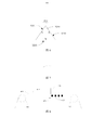
- FIG. 2 is a schematic structural view of a magnetic printing apparatus according to a first embodiment of the present invention
- Figure 3 is an end elevational view of the magnetic orienting device in the first embodiment of the present invention.
- Figure 4 is a view showing the effect of the magnetic orientation pattern of the magnetic ink layer in the first embodiment of the present invention
- Figure 5 is an end elevational view of a magnetic orienting device in a second embodiment of the present invention.
- Figure 6 is an end elevational view of a magnetic orienting device in a third embodiment of the present invention.
- Figure 7 is an effect diagram of a magnetic orientation pattern of a magnetic ink layer in a third embodiment of the present invention.
- Figure 8 is a schematic structural view of a magnetic printing apparatus according to a fourth embodiment of the present invention.
- Figure 9 is a flow chart of a magnetic printing method in accordance with a fifth embodiment of the present invention.
- FIG. 2 is a schematic structural view of a magnetic printing apparatus according to a first embodiment of the present invention.
- the magnetic printing apparatus is a drum type continuous printing apparatus including printing apparatuses 110, 111, magnetic orienting means 123, curing means 130, and conveying means 120.
- the transport device 120 transports the printed substrate 100 through the printing devices 110, 111, the magnetic orientation device 123, and the curing device 130.
- the printing apparatuses 110, 111 are respectively provided in a cylindrical shape, and further, magnetic ink can be applied on the printed matter substrate 100 to be printed by roll printing to form a magnetic ink layer (not shown).
- the printed substrate 100 may be a flexible material such as paper, cardboard, film, or plastic that requires magnetic printing.
- the magnetic ink layer contains a magnetic pigment flake (not shown) that can be oriented in the direction of the magnetic field, such as a magnetic optical pigment flake.
- the conveying device 120 is a drum
- the magnetic orienting device 123 is disposed inside the drum 120, and is driven to rotate synchronously with the drum 120 about a rotating shaft 121 under the driving of a driving device (not shown), thereby causing the drum 120 to be rotated.
- the magnetic field generated by the magnetic orienting means 123 during the movement of the printed substrate 100 magnetically orients the magnetic pigment flakes coated in the magnetic ink layer on the surface of the printed substrate 100.
- a plurality of magnetic orienting devices 123 are disposed along the circumference of the drum 120 inside the drum 120.
- the curing device 130 is disposed outside the drum 120 for solidifying the magnetic ink layer after the magnetic orienting device 123 magnetically orients the magnetic pigment flakes in the magnetic ink layer.
- the curing device 130 can employ a variety of suitable sources of curing radiation, such as an ultraviolet source, a source of heat radiation, and any other device capable of curing the layer of magnetic ink onto the printed substrate 100.
- the magnetic orienting device 123 is a cylindrical prism-shaped columnar magnet, specifically including four side surfaces 1231, 1232, 1233 and 1234 and an end surface 1235 connecting the side surfaces 1231, 1232, 1233 and 1234.
- the columnar magnet 123 has a square shape when viewed from the end surface 1235, wherein two adjacent side faces 1231, 1232 are S pole side faces, and the other two adjacent side faces 1233, 1234 are N pole side faces, thereby making S
- the distance between the pole side faces 1231, 1232 and the N pole side faces 1233, 1234 gradually decreases from the center to the both sides along the diagonal of the end face 1235.
- At least one of the S pole side and the N pole side of the columnar magnet 123 may be designed to include at least two planes connected at a predetermined angle (for example, 90 degrees) such that when viewed from the end surface
- a predetermined angle for example, 90 degrees
- Other shapes such as diamonds, rectangles, trapezoids, etc.
- the magnetic orienting device 223 is an elliptical cylindrical magnet.
- the columnar magnet 223 has an elliptical shape as viewed from the end surface 2233.
- the side surface is divided into an S pole side surface 2231 and an N pole side surface 2232 along the long axis direction of the ellipse.
- two symmetrical arcuate magnetic orientation patterns can also be formed inside the magnetic ink layer.
- the S-pole side and the N-pole side may also be divided along the short axis of the ellipse.
- At least one of the S pole side surface and the N pole side surface of the columnar magnet 223 may be any other curved curved surface as viewed from the end surface.
- the effect of the magnetic orientation pattern of the magnetic ink layer is similar to that of the previous embodiment.
- the magnetic orienting device 323 is a triangular prism-shaped columnar magnet.
- the columnar magnet 323 has a triangular shape as viewed from the end face 3234.
- the two side faces 3231, 3232 are S pole side faces 3231, 3232, and the other side faces 3233 are N pole side faces 3233.
- an arcuate magnetic orientation pattern may be formed inside the magnetic ink layer, as shown in FIG.
- the magnetic orientation device of the magnetic printing apparatus of the present invention includes at least one columnar magnet including an S pole side surface, an N pole side surface, and an end surface connecting the S pole side surface and the N pole side surface, the S pole side surface and the N pole side At least one of the side faces is curved as viewed from the end face such that the distance between the S pole side face and the N pole side face gradually changes toward the lateral direction of the columnar magnet.
- an arcuate magnetic orientation pattern can be formed in the magnetic ink layer.
- Figure 8 is a block diagram showing the structure of a magnetic printing apparatus in accordance with a fourth embodiment of the present invention.
- the magnetic printing apparatus is a batch type printing apparatus including conveying means 411, 412, printing means 410, magnetic orienting means 420, and curing means 430.
- the conveying devices 411, 412 are used to convey the printed substrate 400 through the printing device 411, the magnetic orienting device 420, and the curing device 430 in an intermittent manner.
- the printing device 411 is a lithographic printing device (for example, a screen printing device or a gravure printing device) that coats the magnetic ink layer on the printed substrate 400 at the conveying gap of the conveying devices 411, 412.
- a lithographic printing device for example, a screen printing device or a gravure printing device
- the magnetic orienting device 420 preferably includes a plurality of columnar magnets 423 arranged in an array for magnetically orienting the magnetic pigment flakes in the magnetic ink layer on the printed substrate 400 at the transport gaps of the transport devices 411, 412.
- the curing device 430 is disposed opposite to the magnetic orientation device 420 on both sides of the printed substrate 400. In the present embodiment, the curing device 430 is disposed above the magnetic orientation device 420. After the magnetic orienting device 420 magnetically orients the magnetic pigment flakes in the magnetic ink layer, the curing device 430 cures the magnetic ink layer.
- the columnar magnet 423 may employ any of the columnar magnets described in the above embodiments, and details are not described herein again.
- the columnar magnet is, for example, a permanent magnet such as aluminum nickel cobalt, ferrite, neodymium iron boron, samarium cobalt alloy, iron chromium cobalt alloy, iron nickel copper alloy, manganese aluminum carbon alloy, platinum cobalt alloy, and Platinum iron alloys, etc.
- the three-dimensional shape of the columnar magnet may be a long column, a trapezoidal body, or the like.
- the magnetic ink layer can be cured in a self-drying manner, such as infrared drying, hot drying, air drying, and the like.
- the above magnetic printing apparatus is not limited to printing of a whole roll of paper or other printed matter substrate, and printing of a single sheet of paper or other printed matter substrate is also possible.
- Figure 9 is a flow chart of a magnetic printing method in accordance with a fifth embodiment of the present invention.
- the magnetic printing method includes:
- step S501 a printed substrate coated with a magnetic ink layer is provided, and the magnetic ink layer contains a plurality of magnetic pigment flakes.
- a columnar magnet in step S502, includes an S pole side surface, an N pole side surface, and an end surface connecting the S pole side surface and the N pole side surface, and at least one of the S pole side surface and the N pole side surface is a curved surface as viewed from the end surface.
- at least one of the S pole side surface and the N pole side surface is an arcuate curved surface as viewed from the end surface, or includes at least two planes joined at a predetermined angle.
- the cylindrical magnet is a regular quadrangular prism in which two adjacent sides are S-pole sides and the other two adjacent sides are N-pole sides.
- step S503 the printed substrate is placed above or below the end face to form an arcuate magnetic orientation pattern in the magnetic ink layer.
- step S504 the magnetic ink layer is cured.
- At least one of the S pole side surface and the N pole side surface of the columnar magnet used in the magnetic printing apparatus and the magnetic printing method of the present invention is a curved surface as viewed from the end surface, and the printed matter substrate is disposed above or below the end surface, Further, a unique curved magnetic orientation pattern can be formed in the magnetic ink layer, so that the printed matter produces a varied pattern effect.
Abstract
Description
Claims (14)
- 一种磁性印刷设备,其中,所述磁性印刷设备包括:A magnetic printing apparatus, wherein the magnetic printing apparatus comprises:印刷装置,用于在印刷品衬底上涂布磁性油墨,以形成磁性油墨层,其中所述磁性油墨层中包含多个磁性颜料片;a printing device for coating a magnetic ink on a printed substrate to form a magnetic ink layer, wherein the magnetic ink layer comprises a plurality of magnetic pigment flakes;磁定向装置,用于对所述磁性油墨层中的所述磁性颜料片进行磁定向;a magnetic orientation device for magnetically orienting the magnetic pigment flakes in the magnetic ink layer;固化装置,用于固化所述磁性油墨层;a curing device for curing the magnetic ink layer;传送装置,用于传送所述印刷品衬底经过所述印刷装置、所述磁定向装置与所述固化装置;a conveying device for conveying the printed substrate through the printing device, the magnetic orientation device and the curing device;其中,所述磁定向装置包括至少一柱状磁体,所述柱状磁体包括S极侧面、N极侧面以及连接所述S极侧面和所述N极侧面的端面,从所述端面观察所述S极侧面和所述N极侧面中的至少一个包括以预定角度连接的至少两个平面,所述印刷品衬底设置于所述端面的上方或下方,以在所述磁性油墨层中形成弧形磁定向图案。Wherein the magnetic orienting device comprises at least one columnar magnet, the columnar magnet comprising an S pole side surface, an N pole side surface, and an end surface connecting the S pole side surface and the N pole side surface, the S pole being viewed from the end surface At least one of a side surface and the N-pole side surface includes at least two planes connected at a predetermined angle, the printed substrate being disposed above or below the end surface to form a curved magnetic orientation in the magnetic ink layer pattern.
- 根据权利要求1所述的磁性印刷设备,其中,所述预定角度为九十度。The magnetic printing apparatus according to claim 1, wherein said predetermined angle is ninety degrees.
- 根据权利要求1所述的磁性印刷设备,其中,所述柱状磁体为正四棱柱,其中两个相邻侧面为所述S极侧面,另外两个相邻侧面为所述N极侧面。 The magnetic printing apparatus according to claim 1, wherein said columnar magnet is a regular square prism, wherein two adjacent sides are said S pole side, and the other two adjacent sides are said N pole side.
- 根据权利要求1所述的磁性印刷设备,其中,所述传送装置包括滚筒,所述柱状磁体设置于所述滚筒内,并随所述滚筒同步转动。The magnetic printing apparatus according to claim 1, wherein said conveying means comprises a drum, said columnar magnet being disposed in said drum and rotating in synchronization with said drum.
- 一种磁性印刷设备,其中,所述磁性印刷设备包括:A magnetic printing apparatus, wherein the magnetic printing apparatus comprises:印刷装置,用于在印刷品衬底上涂布磁性油墨,以形成磁性油墨层,其中所述磁性油墨层中包含多个磁性颜料片;a printing device for coating a magnetic ink on a printed substrate to form a magnetic ink layer, wherein the magnetic ink layer comprises a plurality of magnetic pigment flakes;磁定向装置,用于对所述磁性油墨层中的所述磁性颜料片进行磁定向;a magnetic orientation device for magnetically orienting the magnetic pigment flakes in the magnetic ink layer;固化装置,用于固化所述磁性油墨层;a curing device for curing the magnetic ink layer;其中,所述磁定向装置包括至少一柱状磁体,所述柱状磁体包括S极侧面、N极侧面以及连接所述S极侧面和所述N极侧面的端面,从所述端面观察所述S极侧面和所述N极侧面中的至少一个为曲面,所述印刷品衬底设置于所述端面的上方或下方,以在所述磁性油墨层中形成弧形磁定向图案。Wherein the magnetic orienting device comprises at least one columnar magnet, the columnar magnet comprising an S pole side surface, an N pole side surface, and an end surface connecting the S pole side surface and the N pole side surface, the S pole being viewed from the end surface At least one of the side surface and the N-pole side surface is a curved surface, and the printed matter substrate is disposed above or below the end surface to form an arcuate magnetic orientation pattern in the magnetic ink layer.
- 根据权利要求5所述的磁性印刷设备,其中,从所述端面观察,所述S极侧面和所述N极侧面中的至少一个为弧形曲面。The magnetic printing apparatus according to claim 5, wherein at least one of the S-pole side surface and the N-pole side surface is a curved curved surface as viewed from the end surface.
- 根据权利要求5所述的磁性印刷设备,其中,从所述端面观察,所述S极侧面和所述N极侧面中的至少一个包括以预定角度连接的至少两个平面。The magnetic printing apparatus according to claim 5, wherein at least one of the S pole side surface and the N pole side surface includes at least two planes connected at a predetermined angle as viewed from the end surface.
- 根据权利要求7所述的磁性印刷设备,其中,所述预定角度为九十度。The magnetic printing apparatus according to claim 7, wherein said predetermined angle is ninety degrees.
- 根据权利要求5所述的磁性印刷设备,其中,所述柱状磁体为正四棱柱,其中两个相邻侧面为所述S极侧面,另外两个相邻侧面为所述N极侧面。The magnetic printing apparatus according to claim 5, wherein said columnar magnet is a regular square prism, wherein two adjacent sides are said S pole side, and the other two adjacent sides are said N pole side.
- 根据权利要求5所述的磁性印刷设备,其中,所述磁性印刷设备进一步包括传送装置,用于传送所述印刷品衬底经过所述印刷装置、所述磁定向装置与所述固化装置。A magnetic printing apparatus according to claim 5, wherein said magnetic printing apparatus further comprises conveying means for conveying said printed substrate through said printing means, said magnetic orienting means and said curing means.
- 根据权利要求10所述的磁性印刷设备,其中,所述传送装置包括滚筒,所述柱状磁体设置于所述滚筒内,并随所述滚筒同步转动。The magnetic printing apparatus according to claim 10, wherein said conveying means comprises a drum, said columnar magnet being disposed in said drum and rotating in synchronization with said drum.
- 一种磁性印刷方法,其中,所述磁性印刷方法包括步骤:A magnetic printing method, wherein the magnetic printing method comprises the steps of:提供涂布有磁性油墨层的印刷品衬底,所述磁性油墨层中包含多个磁性颜料片;Providing a printed substrate coated with a magnetic ink layer, the magnetic ink layer comprising a plurality of magnetic pigment flakes;提供柱状磁体,所述柱状磁体包括S极侧面、N极侧面以及连接所述S极侧面和所述N极侧面的端面,从所述端面观察所述S极侧面和所述N极侧面中的至少一个为曲面;Providing a columnar magnet including an S pole side surface, an N pole side surface, and an end surface connecting the S pole side surface and the N pole side surface, the S pole side surface and the N pole side surface being viewed from the end surface At least one is a curved surface;将所述印刷品衬底设置于所述端面的上方或下方,以在所述磁性油墨层中形成弧形磁定向图案;Forming the printed substrate above or below the end surface to form an arcuate magnetic orientation pattern in the magnetic ink layer;固化所述磁性油墨层。The magnetic ink layer is cured.
- 根据权利要求12所述的磁性印刷方法,其中,从所述端面观察,所述S极侧面和所述N极侧面中的至少一个为弧形曲面,或者包括以预定角度连接的至少两个平面。The magnetic printing method according to claim 12, wherein at least one of the S pole side surface and the N pole side surface is an arcuate curved surface or at least two planes connected at a predetermined angle as viewed from the end surface .
- 根据权利要求12所述的磁性印刷方法,其中,所述柱状磁体为正四棱柱,其中两个相邻侧面为所述S极侧面,另外两个相邻侧面为所述N极侧面。The magnetic printing method according to claim 12, wherein said columnar magnet is a regular square prism, wherein two adjacent sides are said S-pole sides, and the other two adjacent sides are said N-pole sides.
Priority Applications (3)
| Application Number | Priority Date | Filing Date | Title |
|---|---|---|---|
| US14/419,242 US20150202653A1 (en) | 2012-08-03 | 2013-06-25 | Magnetic printing apparatus and magnetic printing method |
| IN802DEN2015 IN2015DN00802A (en) | 2012-08-03 | 2013-06-25 | |
| GB1502046.4A GB2519042B (en) | 2012-08-03 | 2013-06-25 | Magnetic printing equipment and magnetic printing method |
Applications Claiming Priority (2)
| Application Number | Priority Date | Filing Date | Title |
|---|---|---|---|
| CN201210277677.0 | 2012-08-03 | ||
| CN201210277677.0A CN102825903B (en) | 2012-08-03 | 2012-08-03 | Magnetic printing equipment and magnetic printing method |
Publications (1)
| Publication Number | Publication Date |
|---|---|
| WO2014019423A1 true WO2014019423A1 (en) | 2014-02-06 |
Family
ID=47329308
Family Applications (1)
| Application Number | Title | Priority Date | Filing Date |
|---|---|---|---|
| PCT/CN2013/077882 WO2014019423A1 (en) | 2012-08-03 | 2013-06-25 | Magnetic printing equipment and magnetic printing method |
Country Status (5)
| Country | Link |
|---|---|
| US (1) | US20150202653A1 (en) |
| CN (1) | CN102825903B (en) |
| GB (1) | GB2519042B (en) |
| IN (1) | IN2015DN00802A (en) |
| WO (1) | WO2014019423A1 (en) |
Families Citing this family (12)
| Publication number | Priority date | Publication date | Assignee | Title |
|---|---|---|---|---|
| CN102825903B (en) * | 2012-08-03 | 2015-06-17 | 惠州市华阳光学技术有限公司 | Magnetic printing equipment and magnetic printing method |
| CN103448361B (en) * | 2013-08-26 | 2015-06-17 | 惠州市华阳光学技术有限公司 | Magnetic orienting device for magnetic pigment printing and printing device |
| CN103950279B (en) * | 2014-05-15 | 2016-02-10 | 常德金鹏印务有限公司 | A kind of printing equipment of belt variable figure magnetic orientation device |
| CN103950280B (en) * | 2014-05-15 | 2016-01-20 | 常德金鹏印务有限公司 | A kind of printing equipment realizing magnetic orientation combination |
| CN104260572B (en) * | 2014-09-26 | 2016-11-23 | 惠州市华阳光学技术有限公司 | A kind of magnetic orientation pattern and preparation method thereof |
| CN104401117B (en) * | 2014-11-05 | 2017-06-06 | 广东乐佳印刷有限公司 | The circular-oriented printing equipment and method of a kind of magnetic ink |
| CN104385779B (en) * | 2014-11-26 | 2017-06-06 | 广东乐佳印刷有限公司 | A kind of triangle circular-oriented apparatus and method of magnetic ink |
| CN105346329B (en) * | 2015-12-11 | 2018-09-14 | 常德金鹏印务有限公司 | A kind of three-dimensional dynamic depth of field security pattern printed matter and its printing process greatly |
| CN107128065B (en) * | 2017-04-01 | 2020-07-17 | 惠州市华阳光学技术有限公司 | Magnetic printing apparatus and columnar magnet |
| CN109720112A (en) * | 2018-11-21 | 2019-05-07 | 惠州市嘉信达科技有限公司 | A kind of slightly-embossed carving light of 3D magnetism becomes the printing process of reverse tone |
| CN110481145B (en) * | 2019-09-16 | 2021-03-26 | 浙江澳美新材料股份有限公司 | Variable-pattern magnetic printing roller |
| CN114701250B (en) * | 2022-03-18 | 2023-05-26 | 山东泰宝信息科技集团有限公司 | Magnetic 3D light variable magnetic equipment |
Citations (6)
| Publication number | Priority date | Publication date | Assignee | Title |
|---|---|---|---|---|
| JPH09254436A (en) * | 1996-03-25 | 1997-09-30 | Iwatsu Electric Co Ltd | Magnetic printing device |
| JP2009090624A (en) * | 2007-10-12 | 2009-04-30 | Minoguruupu:Kk | Magnetic printing method |
| CN202071524U (en) * | 2011-01-27 | 2011-12-14 | 李玉龙 | Magnetized anti-counterfeit printed matter and dedicated printing device of magnetized anti-counterfeit printed matter |
| CN102442097A (en) * | 2010-09-30 | 2012-05-09 | 王玉珠 | Magnetic printing method and printing product thereof |
| CN102529326A (en) * | 2011-12-02 | 2012-07-04 | 惠州市华阳光学技术有限公司 | Magnetic orientation device, manufacture device and manufacture method of magnetic pigment printed product |
| CN102825903A (en) * | 2012-08-03 | 2012-12-19 | 惠州市华阳光学技术有限公司 | Magnetic printing equipment and magnetic printing method |
Family Cites Families (4)
| Publication number | Priority date | Publication date | Assignee | Title |
|---|---|---|---|---|
| US7047883B2 (en) * | 2002-07-15 | 2006-05-23 | Jds Uniphase Corporation | Method and apparatus for orienting magnetic flakes |
| US7934451B2 (en) * | 2002-07-15 | 2011-05-03 | Jds Uniphase Corporation | Apparatus for orienting magnetic flakes |
| DE102010041398A1 (en) * | 2009-10-22 | 2011-04-28 | Manroland Ag | Device and method for coating |
| CN102490448B (en) * | 2011-10-20 | 2014-01-15 | 惠州市华阳光学技术有限公司 | Magnetic printing mother set, preparation method thereof and preparation equipment |
-
2012
- 2012-08-03 CN CN201210277677.0A patent/CN102825903B/en active Active
-
2013
- 2013-06-25 US US14/419,242 patent/US20150202653A1/en not_active Abandoned
- 2013-06-25 GB GB1502046.4A patent/GB2519042B/en active Active
- 2013-06-25 IN IN802DEN2015 patent/IN2015DN00802A/en unknown
- 2013-06-25 WO PCT/CN2013/077882 patent/WO2014019423A1/en active Application Filing
Patent Citations (6)
| Publication number | Priority date | Publication date | Assignee | Title |
|---|---|---|---|---|
| JPH09254436A (en) * | 1996-03-25 | 1997-09-30 | Iwatsu Electric Co Ltd | Magnetic printing device |
| JP2009090624A (en) * | 2007-10-12 | 2009-04-30 | Minoguruupu:Kk | Magnetic printing method |
| CN102442097A (en) * | 2010-09-30 | 2012-05-09 | 王玉珠 | Magnetic printing method and printing product thereof |
| CN202071524U (en) * | 2011-01-27 | 2011-12-14 | 李玉龙 | Magnetized anti-counterfeit printed matter and dedicated printing device of magnetized anti-counterfeit printed matter |
| CN102529326A (en) * | 2011-12-02 | 2012-07-04 | 惠州市华阳光学技术有限公司 | Magnetic orientation device, manufacture device and manufacture method of magnetic pigment printed product |
| CN102825903A (en) * | 2012-08-03 | 2012-12-19 | 惠州市华阳光学技术有限公司 | Magnetic printing equipment and magnetic printing method |
Also Published As
| Publication number | Publication date |
|---|---|
| GB2519042B (en) | 2016-08-24 |
| GB201502046D0 (en) | 2015-03-25 |
| IN2015DN00802A (en) | 2015-07-03 |
| GB2519042A (en) | 2015-04-08 |
| US20150202653A1 (en) | 2015-07-23 |
| CN102825903B (en) | 2015-06-17 |
| CN102825903A (en) | 2012-12-19 |
Similar Documents
| Publication | Publication Date | Title |
|---|---|---|
| WO2014019423A1 (en) | Magnetic printing equipment and magnetic printing method | |
| WO2014019472A1 (en) | Magnetic printing apparatus | |
| CN102529326B (en) | Magnetic orientation device, manufacture device and manufacture method of magnetic pigment printed product | |
| WO2013152696A1 (en) | Method and device for manufacturing magnetic-orientation printing master and magnetic pigment presswork | |
| Smith et al. | Magnetic microhelix coil structures | |
| CN109478014B (en) | Apparatus for imprinting discrete substrates using a flexible stamp | |
| US8211509B2 (en) | Alignment of paste-like ink having magnetic particles therein, and the printing of optical effects | |
| CN205871453U (en) | Magnetic ink printing equipment and magnetism orienting device | |
| CN203391459U (en) | Magnetic printing equipment | |
| CN102249089B (en) | Conveying device | |
| KR101385874B1 (en) | Printing apparatus and printing method | |
| BRPI0414184B1 (en) | Micro-replicated article and method for manufacturing it | |
| TW201609276A (en) | Two-axial alignment of magnetic platelets | |
| WO2011052895A2 (en) | Roll imprinting apparatus | |
| CN104349902A (en) | Inkjet printing device and printing method | |
| EP3507026A1 (en) | Orienting magnetically-orientable flakes | |
| WO2023284208A1 (en) | Multi-optical-color optically variable printing apparatus and printing method thereof | |
| US10821759B2 (en) | System for forming safety pattern by magnetic and optical field | |
| CN108943999A (en) | Predrying curing mechanism, screen process press and printing process | |
| CN102490448A (en) | Magnetic printing mother set, preparation method thereof and preparation equipment | |
| EP2716371A1 (en) | Method for manufacturing design medium and design medium | |
| CN101992586B (en) | Holographic positioning molding method and system | |
| WO2018176576A1 (en) | Magnetic printing apparatus and columnar magnet | |
| WO2014175535A1 (en) | Apparatus and method for solution transfer-type imprint lithography using roll stamp | |
| KR101530749B1 (en) | Both sided printing apparatus and method |
Legal Events
| Date | Code | Title | Description |
|---|---|---|---|
| 121 | Ep: the epo has been informed by wipo that ep was designated in this application |
Ref document number: 13825941 Country of ref document: EP Kind code of ref document: A1 |
|
| WWE | Wipo information: entry into national phase |
Ref document number: 14419242 Country of ref document: US |
|
| NENP | Non-entry into the national phase |
Ref country code: DE |
|
| ENP | Entry into the national phase |
Ref document number: 1502046 Country of ref document: GB Kind code of ref document: A Free format text: PCT FILING DATE = 20130625 |
|
| WWE | Wipo information: entry into national phase |
Ref document number: 1502046.4 Country of ref document: GB |
|
| 122 | Ep: pct application non-entry in european phase |
Ref document number: 13825941 Country of ref document: EP Kind code of ref document: A1 |