WO2014017202A1 - 表示装置 - Google Patents
表示装置 Download PDFInfo
- Publication number
- WO2014017202A1 WO2014017202A1 PCT/JP2013/066183 JP2013066183W WO2014017202A1 WO 2014017202 A1 WO2014017202 A1 WO 2014017202A1 JP 2013066183 W JP2013066183 W JP 2013066183W WO 2014017202 A1 WO2014017202 A1 WO 2014017202A1
- Authority
- WO
- WIPO (PCT)
- Prior art keywords
- main body
- display device
- guide groove
- center
- engagement portion
- Prior art date
- Legal status (The legal status is an assumption and is not a legal conclusion. Google has not performed a legal analysis and makes no representation as to the accuracy of the status listed.)
- Ceased
Links
Images


















Classifications
-
- A—HUMAN NECESSITIES
- A47—FURNITURE; DOMESTIC ARTICLES OR APPLIANCES; COFFEE MILLS; SPICE MILLS; SUCTION CLEANERS IN GENERAL
- A47G—HOUSEHOLD OR TABLE EQUIPMENT
- A47G1/00—Mirrors; Picture frames or the like, e.g. provided with heating, lighting or ventilating means
- A47G1/16—Devices for hanging or supporting pictures, mirrors, or the like
- A47G1/166—Devices for hanging or supporting pictures, mirrors, or the like for rotatably hanging or supporting
Definitions
- the present invention relates to a thin display device provided with a rectangular display surface on a main body and installed on a mounting surface such as a wall surface or a ceiling.
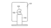
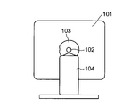
- a cam portion 103 is provided on a horizontal rotation shaft 102 passing through the center of a display portion 101 having a substantially rectangular display surface.
- a rotating mechanism 201 as shown in FIG. 15 is also commercially available. By attaching such a rotation mechanism 201 to the back surface of the display device 202 and attaching the display device 202 to the wall surface via the rotation mechanism 201, the display device 202 is placed in a horizontal state or a vertical state with respect to the wall surface. Can be rotated.
- JP 2004-078073 A (refer to claim 1, FIG. 1, FIG. 4, FIG. 7, FIG. 10, etc.)
- Japanese Patent Laid-Open No. 11-338363 (refer to claim 1, FIGS. 1 to 5)
- the rotation mechanism of the conventional display device is often configured to rotate around the center point of the display unit, and a smooth rotation operation can be obtained.
- a fixing mechanism including a cam mechanism for stopping rotation at a desired position and fixing the angle was necessary.
- the rotation mechanism and the fixing mechanism provided separately from the display unit often have a thick structure. For this reason, when installing the display device on a wall, the display unit (main body) and the wall surface In the meantime, a gap corresponding to the rotation mechanism and the fixing mechanism is formed widely.
- a wide gap is formed between the display device 202 and the wall surface P by the thickness of the rotation mechanism 201. In this case, not only does a feeling of pressure occur when hanging on the wall, but it also becomes impossible to make use of the original characteristic of the display device called “thin”.
- the present invention has been made to solve the above-described problems, and the purpose of the present invention is to install the display device close to the mounting surface, and in the position close to the mounting surface, the horizontally installed state and the vertically installed state by rotation. It is to provide a display device capable of changing the installation state between the two and fixing the position in each of the installation states.
- a display device is provided with a rectangular display surface on a main body, is installed on a mounting surface so that the display surface is horizontally long or vertically long, and is rotated horizontally by rotating the main body.
- a thin display device in which an installation state transitions between a state and a vertically long installation state, wherein the main body is provided with a guide groove into which a suspension pin attached to the attachment surface is inserted, and the guide The groove has a first engagement portion that fixes the rotation position of the main body at the position of the horizontally long installation state by the suspension pin being caught by the weight of the main body in the horizontally long installation state, and the vertically long installation state.
- the second engaging portion that fixes the rotational position of the main body at the position of the vertically long installation state, the first engaging portion, and the second second A structure having a coupling groove for coupling the engaging portion.
- the main body can be rotated and fixed without providing a thick rotating mechanism or fixing mechanism between the main body of the display device and the mounting surface (for example, a wall surface).
- a display apparatus can be installed close to a mounting surface.
- the guide groove is positioned at a position other than the center of the display surface.
- the installation state transitions between the horizontally installed state and the vertically installed state by rotation at a position close to the attached surface.
- the suspension pin is hooked on the first engagement portion or the second engagement portion, so that the position of the display device can be fixed at each of the horizontally installed state and the vertically installed state.
- the display device can be installed close to the mounting surface, and even at a position close to the mounting surface, the installation state is changed between the horizontal installation state and the vertical installation state by rotation, and the display device Can be fixed in each of the above installation states.
- FIG. 3 is a front perspective view of the display device in a horizontal state.
- FIG. 3 is a front perspective view of the display device in a vertically mounted state. It is a front perspective view which expands and shows the said display apparatus in the horizontal state of FIG. 2A.
- FIG. 3B is a cross-sectional view taken along line A-A ′ of FIG. 3A.
- FIG. 3B is a cross-sectional view taken along line B-B ′ of FIG. 3A.
- FIG. 3 is an enlarged front perspective view of the display device in the vertically hung state of FIG. 2B.
- FIG. 4B is a cross-sectional view taken along line A-A ′ of FIG. 4A.
- FIG. 4B is a cross-sectional view taken along line B-B ′ of FIG. 4A.
- FIG. 10 is a front perspective view of a display device according to another embodiment of the present invention in a horizontal state.
- FIG. 5B is a cross-sectional view taken along line A-A ′ of FIG. 5A.
- FIG. 3 is a front perspective view of the display device in a vertically mounted state.
- FIG. 10 is a front perspective view of a display device according to still another embodiment of the present invention in a horizontal state.
- FIG. 6B is a cross-sectional view taken along line A-A ′ of FIG. 6A.
- FIG. 3 is a front perspective view of the display device in a vertically mounted state. It is a rear view of the display apparatus which concerns on other embodiment of this invention. It is a front perspective view in the horizontal installation state of the said display apparatus.
- FIG. 8B is a cross-sectional view taken along line A-A ′ of FIG. 8A. It is a front perspective view in the vertically long installation state of the said display apparatus. It is a front perspective view which shows typically the state transition from the horizontally long installation state of the said display apparatus to a vertically long installation state. It is sectional drawing which shows the installation state of the said display apparatus with respect to the wall surface which is an attachment surface. It is a front view in the horizontal installation state of the display apparatus which concerns on further another embodiment of this invention.
- FIG. 10B is a cross-sectional view taken along line A-A ′ in FIG. 10A. It is a front view in the vertically long installation state of the said display apparatus. It is a top view in the vertically long installation state of the display device. It is a front perspective view which shows typically the state transition from the horizontally long installation state of the said display apparatus to a vertically long installation state. It is sectional drawing which shows the state before the hanging pin attached to the wall surface is hooked on the 1st engaging part or the 2nd engaging part of the said display apparatus. It is sectional drawing in the state in which the said suspending pin was hooked on the said 1st engaging part or the said 2nd engaging part.
- FIG. 13B is a cross-sectional view taken along line A-A ′ in FIG. 13A. It is a front view in the vertically long installation state of the said display apparatus. It is a top view in the vertically long installation state of the display device. It is a rear view in the vertical installation state of the conventional display apparatus. It is a rear view in the horizontal installation state of the conventional display apparatus. It is a perspective view of the conventional rotation mechanism. It is a side view which shows the state which installed the display apparatus in the wall surface via the said rotation mechanism.
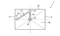
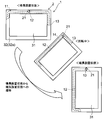
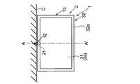
- FIG. 1A and 1B are a front view and a rear view, respectively, of the display device 1 according to the present embodiment in a horizontal state.
- 2A and 2B are front perspective views of the display device 1 in the horizontal state and the vertical state, respectively.
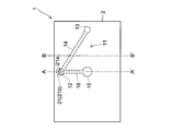
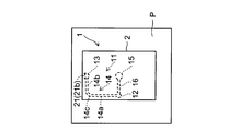
- 3A is an enlarged front perspective view showing the display device 1 in the horizontal state of FIG. 2A
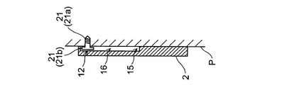
- FIG. 3B is a cross-sectional view taken along the line AA ′ of FIG. 3A
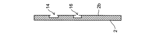
- FIG. FIG. 3B is a sectional view taken along line BB ′ of FIG. 3A.
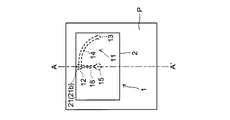
- 4A is an enlarged front perspective view showing the display device 1 in the vertically hung state of FIG. 2B
- FIG. 4B is a cross-sectional view taken along the line AA ′ of FIG. 4A
- FIG. FIG. 4B is a sectional view taken along line BB ′ of FIG. 4A.
- illustration of a wall surface is abbreviate
- the display device 1 has a substantially rectangular parallelepiped main body 2 constituting a thin display device such as an LCD or a PDP.
- the main body 2 is provided with a rectangular (rectangular) display surface 2a for displaying an image.
- a guide groove 11 is provided in the rear chassis 2 b located on the opposite side of the display surface 2 a, and a hanging pin 21 attached to the wall surface P is inserted into the guide groove 11.
- the hanging pin 21 is configured by connecting a rod-shaped portion 21a fixed to the wall surface P and a head portion 21b having a larger diameter than the rod-shaped portion 21a.
- the guide groove 11 includes a first engaging portion 12, a second engaging portion 13, a connecting groove 14, an opening 15, and a guide groove 16.
- the first engaging portion 12 is a hole in which the hanging pin 21 is caught by the weight of the main body 2 in the horizontal state.
- the first engaging portion 12 is parallel to the short side L1 of the back chassis 2b passing through the center O of the rectangular back chassis 2b (intersection of two diagonal lines forming the outline of the back chassis 2b). On the straight line, it is located on the long side L2 side that is above the center O in the horizontal state. As a result, the first engaging portion 12 is positioned above the center O on a vertical line (straight line along the direction of gravity) passing through the center O of the back chassis 2b in the horizontal state. Become. A line A-A ′ in FIG.
- the first engaging portion 12 is located on the long side L2 (one of the two long sides L2) side from the center O of the back chassis 2b and in the center in the direction along the long side L2. ing.
- the second engaging portion 13 is a hole in which the hanging pin 21 is caught by the weight of the main body 2 in the vertically hung state.
- the second engaging portion 13 is located on the short side L1 side that passes through the center O of the back chassis 2b and is parallel to the long side L2 of the back chassis 2b and is above the center O in the vertical state. is doing. Thereby, the 2nd engaging part 13 will be located above the center O on the perpendicular line which passes along the center O of the back surface chassis 2b in a vertical state.
- a line A-A ′ in FIG. 4A corresponds to a vertical line passing through the center O of the back chassis 2 b when the main body 2 is vertically mounted. That is, the second engaging portion 13 is located on the short side L1 (one of the two short sides L1) side from the center O of the back chassis 2b and in the center in the direction along the short side L1. ing.
- the connecting groove 14 is a groove that connects the first engaging portion 12 and the second engaging portion 13, and in the present embodiment, these are connected in a single straight line.
- the first engaging portion 12 and the second engaging portion 13 described above are formed as holes having a diameter larger than the width of the connecting groove 14. In addition, it is good also considering the both ends of the connection groove
- the opening 15 is a circular opening through which the hanging pin 21 fixed to the wall surface P is inserted and removed, and is located at the center O of the back chassis 2b.
- the opening diameter of the opening 15 is set to be larger than the head 21 b of the hanging pin 21.
- the guide groove 16 is a groove for relatively guiding the suspension pin 21 fitted and inserted into the opening 15 toward the first engagement portion 12, and includes the first engagement portion 12 and the opening. 15 is connected.
- the guide groove 16 is configured by connecting the second engagement portion 13 and the opening 15 so as to relatively guide the suspension pin 21 from the opening 15 to the second engagement portion 13. Also good.
- the first engagement portion 12, the second engagement portion 13, the connection groove 14, and the guide groove 16 are larger than the diameter of the rod-shaped portion 21 a of the suspension pin 21 and larger than the diameter of the head portion 21 b.
- the display device 1 when the display device 1 is mounted on the wall, first, the back chassis 2b side of the display device 1 is brought close to the wall surface P, and the opening 15 of the guide groove 11 provided in the back chassis 2b is placed on the wall surface. The head 21b of the hanging pin 21 fixed to P is fitted. Then, the main body 2 is moved (slid) until the suspension pin 21 moves through the guide groove 16 and reaches the first engagement portion 12. At the position of the first engagement portion 12, the main body 2 comes to a standstill when the suspension pin 21 is caught by the first engagement portion 12 due to its own weight, and along the wall surface P as shown in FIG. 3. The rotational position of the main body 2 in the plane is fixed at the position in the horizontal state.
- the main body 2 When the main body 2 is changed from the horizontal state to the vertical state, the main body 2 is moved (sliding, rotating) until the hanging pin 21 moves through the connecting groove 14 and reaches the second engaging portion 13.
- the rotation of the main body 2 may be performed simultaneously with the slide of the main body 2 or may be performed separately from the slide.
- the main body 2 may be slid until the suspension pin 21 reaches the second engagement portion 13, and the main body 2 may be rotated after reaching the position of the second engagement portion 13.
- the main body 2 At the position of the second engaging portion 13, the main body 2 is stopped by the suspension pin 21 being caught by the second engaging portion 13 by its own weight, and along the wall surface P as shown in FIG. 4.
- the rotational position of the main body 2 in the plane is fixed at the position in the vertical state.
- the guide groove 11 is provided in the back chassis 2 b of the main body 2 of the display device 1, and the main body 2 is moved along the guide groove 11 so that the lifting pin 21 moves relatively.
- the main body 2 is shifted between the horizontal state and the vertical state.
- the suspension pin 21 is hooked on the first engagement portion 12 or the second engagement portion 13 by its own weight, so that the main body 2 is fixed in a horizontal state or a vertical state.
- the first engaging portion 12 is on a straight line passing through the center O of the back chassis 2b and parallel to the short side L1 of the back chassis 2b, and on the long side L2 side that is above the center O in the horizontal state. It is located and is located above the center O on a vertical line passing through the center O of the back chassis 2b in the horizontal state.
- the second engagement portion 13 is on the short side L1 side that passes through the center O of the back chassis 2b and is parallel to the long side L2 of the back chassis 2b and is above the center O in the vertical state. In the vertical state, it is positioned above the center O on a vertical line passing through the center O of the back chassis 2b.
- the connecting groove 14 is formed in a single linear shape, the first engaging portion 12 and the second engaging portion 13 are simply connected by a single linear connecting groove 14. With a simple configuration, it is possible to realize transition between the horizontal state and the vertical state of the main body 2.
- the suspension pin 21 is connected by the movement of the main body 2.
- the suspension pin 21 is moved by the weight of the main body 2 to the first engaging portion 12 or the second engaging portion 13. It fits in the hole and gets caught. Thereby, it is possible to avoid the suspension pin 21 from being easily displaced from the first engagement portion 12 or the second engagement portion 13 in the horizontal hanging state or the vertical hanging state, and the position of the main body 2 can be reliably secured. Can be fixed to.
- first engaging portion 12, the second engaging portion 13, the connecting groove 14, and the guide groove 16 are openings that are larger than the diameter of the rod-shaped portion 21a of the hanging pin 21 and smaller than the diameter of the head portion 21b. Since it has a width and is formed in a groove shape into which the head 21b fits, the back surface around the guide groove 11 excluding the opening 15 after the head 21b of the hanging pin 21 is inserted into the opening 15 While the head 2b is hooked by the chassis 2b (preventing the suspending pin 21 from being detached from the guide groove 11), the main body 2 can be changed between the horizontal state and the vertical state. Moreover, since the suspending pin 21 can be inserted / removed in the opening 15 of the guide groove 11, the installation / removal to the wall surface P of the main body 2 can be reliably performed.
- the operator who mounts the main body 2 on a wall can estimate the approximate position of the opening part 15 from the display surface 2a side. . This makes it easy to insert the suspending pin 21 into the opening 15 while aligning the suspending pin 21 fixed to the wall surface P and the opening 15, and facilitates the installation of the main body 2 on the wall P. Can be done.
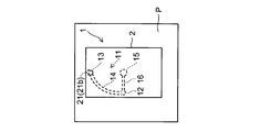
- FIG. 5A is a front perspective view of the display device 1 according to the present embodiment in a horizontal state
- FIG. 5B is a cross-sectional view taken along line AA ′ of FIG. 5A
- FIG. 5C is the display device 1 described above. It is a front perspective view in the state of hanging vertically.
- the connecting groove 14 of the guide groove 11 is the same as that of the first embodiment, except that the first straight portion 14a, the second straight portion 14b, and the curved portion 14c are connected. It is a configuration. That is, in this embodiment, the shape of the connecting groove 14 is set so that a part of the connecting groove 14 draws a gentle curve.
- the curved portion 14c is a curved groove that protrudes from the center O (see FIG. 1B) of the back chassis 2b toward the outer periphery, and the curved portion 14c as a whole is shaped like a fan-shaped arc with a central angle of 90 °. I am doing.
- the first straight portion 14a is a groove that linearly connects one end of the curved portion 14c and the first engaging portion 12 along the outer periphery (long side) of the back chassis 2b.
- the second straight portion 14b is a groove that linearly connects the other end of the curved portion 14c and the second engaging portion 13 along the outer periphery (short side) of the back chassis 2b.
- the main body 2 is placed in a horizontal state and a vertical state.
- the main body 2 may move so that the suspension pin 21 slides relatively linearly from end to end of the connecting groove 14.
- the 1st straight line part 14a and the 2nd straight line part 14b are connected by the curve part 14c, and the connection groove 14 is comprised, and the connection groove 14 is a single straight line.
- the main body 2 is transitioned between the horizontal state and the vertical state, for example, the main body 2 is slid in the horizontal direction along the first straight portion 14a, rotated 90 °, A stepwise operation of sliding in the lateral direction along the second straight line portion 14b is performed. Therefore, the main body 2 does not slide linearly from the position in the horizontal state to the position in the vertical state, and the state transition between the horizontal state and the vertical state (movement of the main body 2) is performed safely. be able to.
- connection groove 14 of the guide groove 11 has the same configuration as that of the first embodiment except that the connection groove 14 is formed in a curved shape that protrudes toward the outer periphery (from the center O) of the back chassis 2b. is there.
- the connecting groove 14 is formed in a shape that draws a gentler curve than the connecting portion 14c of the second embodiment.
- the connecting groove 14 is curved as a whole, when the main body 2 is transitioned between the horizontally hung state and the vertically hung state, the main body 2 is slightly linear along the connecting groove 14. None move on. Thereby, the state transition (movement of the main body 2) between the horizontal state and the vertical state can be performed more safely than in the second embodiment.
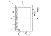
- FIG. 7 is a rear view of the display device 1 of the present embodiment.
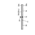
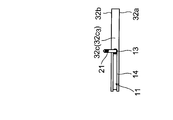
- the main body 2 of the display device 1 includes a display unit main body 31 having a display surface 2a (see FIG. 8A) and an outer peripheral frame 32 serving as an outer frame of the display unit main body 31, and guide grooves 11 (including the first engaging portion 12, the second engaging portion 13, and the connecting groove 14) is the same as that of the first embodiment except that the outer peripheral frame 32 is provided.
- the outer peripheral frame 32 has a front surface portion 32a (see FIG. 8A), a back surface portion 32b, and a side surface portion 32c.
- the front surface portion 32a is formed in a frame shape on the display surface 2a side of the main body 2 along the outer periphery of the display surface 2a.
- the back surface portion 32b is formed in a frame shape on the back surface side opposite to the display surface 2a of the main body 2, and is positioned so as to face the front surface portion 32a with a gap.
- the side surface portion 32c connects the front surface portion 32a and the back surface portion 32b at the outermost periphery of each other to constitute the outermost periphery of the frame.
- the guide groove 11 is provided in the back surface part 32b of the outer periphery frame 32, and the suspension pin 21 attached to the wall surface P (refer FIG. 8B) as an attachment surface is inserted in the guide groove 11. It has become.
- the first engaging portion 12 of the guide groove 11 is formed in one of the two longitudinal portions 32b 1 and 32b 2 (for example, the longitudinal portion 32b 1 ) along the longitudinal direction of the display surface 2a in the back surface portion 32b.
- the second engaging portion 13 is configured so that one of the two short portions 32b 3 and 32b 4 (for example, the short portion 32b 3 ) along the short direction of the display surface 2a in the back surface portion 32 has the short width.
- the connection groove 14 is provided in the long portion 32 b 1 and the short portion 32 b 3 of the back surface portion 32, and connects the first engagement portion 12 and the second engagement portion 13.
- the first engaging portion 12 and the third engaging portion 13 are semicircles in which the suspension pin 21 is hooked in a horizontally hanging state (horizontal installation state) and a vertically hanging state (vertical installation state) by the weight of the main body 2. It consists of parts.
- the second engaging portion 13 is formed with respect to the display surface 2a and extending in the short direction of the display surface 2a.
- An insertion port 17 is formed in the surface located on the opposite side to the side.
- the insertion port 17 is an opening through which the suspension pin 21 is inserted and removed, and is connected to the first engagement portion 12 through the guide groove 16 of the guide groove 11. Accordingly, the suspension pin 21 inserted from the insertion port 17 passes through the guide groove 16 and is relatively guided toward the first engagement portion 12.
- the insertion port 17 extends in the longitudinal direction of the display surface 2a among the four surfaces constituting the side surface portion 32c of the outer peripheral frame 32, and the first engagement portion 12 is formed on the display surface 2a. It is provided in the surface located on the opposite side, and may be connected to the second engaging portion 13 via a guide groove. In this case, the suspension pin 21 inserted from the insertion port 17 passes through the guide groove and is relatively guided toward the second engagement portion 13.
- FIG. 8A is a front perspective view of the display device 1 of the present embodiment in a horizontally installed state
- FIG. 8B is a cross-sectional view taken along the line AA ′ of FIG. 8A
- FIG. 8C is the display device 1 described above. It is a front perspective view in the vertical installation state.
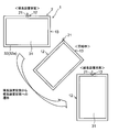
- 9A is a front perspective view schematically showing a state transition of the display device 1 from the horizontally long installation state to the vertically long installation state
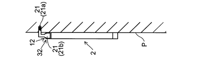
- FIG. 9B shows the installation state of the display device 1 with respect to the wall surface P that is the mounting surface. It is sectional drawing shown.
- the suspending pin 21 By inserting the suspending pin 21 into the insertion port 17 and moving the main body 2, the suspending pin 21 can be relatively moved to the first engaging portion 12 through the guide groove 16 of the guide groove 11. it can.
- the main body 2 At the position of the first engaging portion 12, the main body 2 is stationary when the suspension pin 21 is hooked on the first engaging portion 12 by the weight of the main body 2, and the main body 2 is fixed in a horizontally long installation state.
- the main body 2 When the main body 2 is changed from the horizontally long installation state to the vertically long installation state, the main body 2 is moved (sliding, rotating) until the suspension pin 21 moves through the connecting groove 14 and reaches the second engagement portion 13. Let At the position of the second engagement portion 13, the suspension pin 21 is caught by the second engagement portion 13 due to the weight of the body 2, so that the body 2 is stationary and the body 2 is fixed in the vertically installed state.
- the installation state is changed between the horizontally long installation state and the vertically long installation state, and the conventional Rotation and fixation can be realized without providing such a rotation mechanism and fixing mechanism.
- the outer peripheral frame 32 has the front surface portion 32a, the back surface portion 32b, and the side surface portion 32c described above, the guide groove 11 is provided in the back surface portion 32b as in the present embodiment, and the wall surface P
- the main body 2 can be securely placed close to the wall surface P as shown in FIG.
- an installation state can be changed between a horizontally long installation state and a vertically long installation state.
- the suspension pin 21 can be fitted into the guide groove 11 to realize the suspension installation from the wall surface or the ceiling. This will be described later. This will be described in Embodiments 5 and 6.
- the first engagement portion 12 of the guide groove 11 is located in the central longitudinal direction of the display surface 2a in the longitudinal portion 32b 1 of the rear portion 32b
- the second engaging portion 13 includes a rear portion 32b It is located at the center in the transverse direction of the display surface 2a in the lateral portion 32 b 3 of the.
- the opening 15 for inserting and removing the hanging pin 21 at the time of installation is provided in the back chassis 2b (see FIG. 1B and the like) as in the first embodiment
- the opening 15 is provided on the display surface. Since it is hidden by 2a and cannot be seen, when the suspending pin 21 is inserted into the opening 15, it is necessary to predict and insert the approximate position of the opening 15 from the display surface 2a side.
- the insertion port 17 for inserting and removing the suspension pin 21 is provided in the side surface portion 32c of the outer peripheral frame 32 as in the present embodiment, the suspension pin 21 is inserted into the insertion port 17. In doing so, since it can be visually confirmed from the side, the suspension pin 21 can be reliably and easily inserted.
- the suspension pin 21 inserted from the insertion port 17 is guided to the first engagement portion 12 or the second engagement portion 13 by the guide groove 16, and the first engagement portion 12 and the second engagement portion are guided. Transition of the installation state by movement of the main body 2 with the joint portion 13 can be performed.
- FIG. 10A is a front view of the display device 1 according to the present embodiment in a horizontally installed state
- FIG. 10B is a top view of the display device 1 in a horizontally installed state
- FIG. 10C is an A- FIG. 10D is a front view of the display device 1 in a vertically installed state
- FIG. 10E is a top view of the display device 1 in a vertically installed state.
- the guide groove 11 is provided in the side surface portion 32c of the outer peripheral frame 32, and the suspension pin 21 attached to the wall surface P as the attachment surface is bent as shown in FIG. 10C.
- the configuration is the same as that of the fourth embodiment, except that it is inserted into. That is, in this embodiment, the display device 1 (main body 2) is installed suspended from the wall surface P.
- the first engaging portion 12 of the guide groove 11 has the longitudinal direction in one of the two longitudinal portions 32c 1 and 32c 2 (for example, the longitudinal portion 32c 1 ) along the longitudinal direction of the display surface 2a in the side surface portion 32c.
- the second engagement portion 13 is configured so that one of the two short portions 32c 3 and 32c 4 (for example, the short portion 32c 3 ) along the short direction of the display surface 2a in the side surface portion 32c has the short width.
- the opening widths of the first engaging portion 12 and the second engaging portion 13 are formed to be larger than the width of the connecting groove 14 connecting them, and the insertion opening of the hanging pin 21 and the first opening portion are connected to each other.
- the guide groove 16 is formed larger than the width of the guide groove 16 that connects the engagement portion 12 (or the second engagement portion 13).
- the insertion opening is assumed to be formed on the other short side portion 32c 4 of the side surface portion 32c.
- channel 14 and the guide groove 16 is larger than the diameter of the rod-shaped part 21a of the hanging pin 21, and smaller than the diameter (minimum diameter) of the head 21b.
- FIG. 11 is a front perspective view schematically showing a state transition from the horizontally long installed state to the vertically long installed state of the display device 1 of the present embodiment.
- the suspension pin 21 is inserted into the insertion port (not shown) of the side surface portion 32c of the outer peripheral frame 32 and the main body 2 is moved, so that the suspension pin 21 is moved through the guide groove 16 of the guide groove 11 to the first. It can be moved relatively to the engaging portion 12.
- the main body 2 is stationary when the suspension pin 21 is hooked on the first engaging portion 12 by the weight of the main body 2, and the main body 2 is fixed in a horizontally long installation state.
- the main body 2 When the main body 2 is transitioned from the horizontally long installation state to the vertically long installation state, the main body 2 is lifted, the engagement between the hanging pin 21 and the first engaging portion 12 is released, and the hanging pin 21 is connected to the connecting groove.
- the main body 2 is moved (slided or rotated) until the second engaging portion 13 is reached by moving 14. At the position of the second engagement portion 13, the suspension pin 21 is caught by the second engagement portion 13 due to the weight of the body 2, so that the body 2 is stationary and the body 2 is fixed in the vertically installed state.
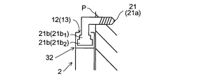
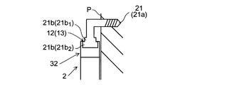
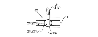
- FIG. 12A is a cross-sectional view showing a state before the hanging pin 21 is hooked on the first engaging portion 12 or the second engaging portion 13, and FIGS. 12B and 12C are suspended by the weight of the main body 2.
- FIG. 6 is a cross-sectional view and a top view of the lower pin 21 in a state where the lower pin 21 is hooked on the first engagement portion 12 or the second engagement portion 13.
- the head 21b of the suspending pin 21 has a shape in which the diameter increases stepwise or continuously toward the side opposite to the side connected to the rod-shaped portion 21a.
- the head 21b includes a small-diameter portion 21b 1 and the large-diameter portion 21b 2 is configured to be connected, the diameter is increased stepwise toward the side opposite to the connection side of the rod-like portion 21a is doing.
- the guide groove 11 has a groove shape into which the head portion 21b of the hanging pin 21 is fitted, and the first engagement portion 12 and the second engagement portion 13 are formed on the small diameter portion 21b 1 which is the minimum diameter of the head portion 21b. greater than the diameter, are formed at the opening of smaller diameter than the diameter of the large diameter portion 21b 2 which is the maximum diameter.
- the hanging pin 21 relatively rises, and the head of the hanging pin 21.
- a part (small diameter part 21b 1 ) of the part 21b fits into the second engagement part 13 (opening part), and at the same time, the rest of the head part 21b (large diameter part 21b 2 ) is caught outside the opening part. Thereby, the relative movement of the main body 2 with respect to the hanging pin 21 is restricted, and the display device 1 is fixed in the vertically long installation state.
- the installation state of the display device 1 can be transitioned between the installation state and the vertically long installation state. Further, since a conventional rotating mechanism and fixing mechanism are unnecessary, the main body 2 can be disposed close to the wall surface P as shown in FIGS. 12A and 12B.
- the 1st engaging part 12 and the 2nd engaging part 13 are each formed by the opening part of the diameter larger than the minimum diameter of the head 21b of the hanging pin 21, and smaller than the maximum diameter, respectively.
- the suspension pin 21 when the suspension pin 21 is at the position of the first engagement portion 12 or the second engagement portion 13, a part of the head 21b of the suspension pin 21 is engaged with the first engagement portion.
- the movement of the main body 2 can be restricted by fitting in the opening of the part 12 or the second engaging part 13. Thereby, the display apparatus 1 can be reliably fixed in a horizontally long installation state or a vertically long installation state.
- FIG. 13A is a front view of the display device 1 according to the present embodiment in a horizontally installed state
- FIG. 13B is a top view of the display device 1 in a horizontally installed state
- FIG. 13C is an A- FIG. 13D is a front view of the display device 1 in a vertically installed state
- FIG. 13E is a top view of the display device 1 in a vertically installed state.
- the configuration is the same as that of the fifth embodiment except that the hanging pin 21 is attached to the ceiling C as the mounting surface and the hanging pin 21 is inserted into the guide groove 11. That is, in the present embodiment, the display device 1 according to the fifth embodiment is installed by being suspended from the ceiling C via the suspension pins 21. It is assumed that the rod-shaped portion 21a of the hanging pin 21 is formed in a straight line and is not bent as in the fifth embodiment.
- the installation state in which the display surface is horizontally long is referred to as a horizontally long installation state, and the display surface is vertically long. Is in the vertically installed state.
- the suspension pin 21 attached to the ceiling C is inserted into the guide groove 11, and the suspension pin 21 is relatively moved along the guide groove 11.
- the installation state of the display device 1 can be transitioned between the horizontally long installation state and the vertically long installation state.
- the state of transition of the installation state at this time is the same as that of the fifth embodiment shown in FIG. 11 (only the mounting surface differs depending on the wall surface P or the ceiling C).
- the main body 2 can be rotated with the position somewhere in the guide groove 11 as the rotation center. That is, the main body 2 can be rotated with the position shifted from the center of the display surface 2 a in the guide groove 11 as the rotation center. Therefore, even if the display device 1 (main body 2) is installed close to the ceiling C, the installation state of the display device 1 can be changed between the horizontally long installation state and the vertically long installation state by rotating the main body 2.
- the apparatus 1 can be installed so as to be rotatable close to the ceiling C.
- the display device 1 shown in the first to fourth embodiments can be suspended from the ceiling C and installed rotatably.
- the display device includes a rectangular display surface on the main body, and is installed on the attachment surface so that the display surface is horizontally long or vertically long.By rotating the main body, a horizontally long installation state and a vertically long installation state are provided.
- the suspension pin is hooked by the weight of the main body, so that the rotation position of the main body is fixed at the position of the horizontally long installed state, and the weight of the main body in the vertically long installed state is
- the suspension pin is hooked by the second engagement portion that fixes the rotation position of the main body at the position of the vertically long installation state, the first engagement portion, and the second engagement portion.
- Linking A structure having a coupling groove that.
- the main body is moved (including rotation) so that the suspension pin moves relatively between the first engagement portion and the second engagement portion via the connection groove.
- the main body can be transitioned between a horizontally long installation state and a vertically long installation state.
- the position of the main body can be fixed in each of the horizontally long installation state and the vertically long installation state because the hanging pin is hooked with the first engagement portion or the second engagement portion.
- the mounting surface is, for example, a wall surface
- the main body (display device) can be installed close to the wall surface without providing a conventional rotating mechanism or fixing mechanism between the main body and the wall surface.
- the main body can be rotated around the position of the guide groove as a rotation center. For example, the position shifted from the center of the display surface in the guide groove The main body can be rotated about the rotation center. Therefore, when the mounting surface is a ceiling, for example, even if the main body is installed close to the ceiling, the installation state can be changed between the horizontally long installation state and the vertically long installation state by rotation.
- the display device can be installed close to the mounting surface (wall surface or ceiling), and the installation state is changed between the horizontally long installation state and the vertically long installation state by rotation even at a position close to the mounting surface. And the position can be fixed.
- the guide groove may be provided on a back chassis opposite to the display surface of the main body, and the suspension pin attached to the wall surface as the attachment surface may be inserted into the guide groove. Good. The above-described effects can be obtained when the guide groove is provided on the rear chassis to perform wall mounting.
- the first engaging portion is located on one long side of the back chassis from the center of the rectangular back chassis and in the center in the direction along the long side, and The engaging portion may be positioned on one short side of the back chassis from the center of the rectangular back chassis and in the center in the direction along the short side.
- the main body when the suspension pin is caught by the first engaging portion due to the weight of the main body, the main body is held in a well-balanced manner without being tilted to the right or left with respect to the wall surface. Can be securely fixed at the position of the horizontally long installation state. Also, when the suspension pin is caught by the second engagement part due to its own weight, hold the main body in a well-balanced manner without tilting it to the right or left side against the wall surface, and adjust the rotational position of the main body. It can be securely fixed at the position of the vertically installed state.
- the display device includes a rectangular display surface on a main body and is installed on a wall surface.
- the display surface is horizontally long (also referred to as a horizontally long installation state) and the display surface is vertically long.
- a thin display device in which the state transitions between (also referred to as a vertically long installation state), and a suspension pin attached to a wall surface is fitted into a rear chassis opposite to the display surface of the main body.
- a guide groove is provided, and when the suspension pin is hooked by the weight of the main body in the horizontal state, the guide groove determines the rotational position of the main body in a plane along the wall surface.
- a first engagement portion that is fixed at a position in a hanging state, and a rotation position of the main body in a plane along the wall surface by the suspension pin being hooked by the weight of the main body in the vertical hanging state.
- a second engaging portion for fixing in position of the vertical hanging state may have a connecting groove for connecting the said first engaging portion and the second engagement portion.
- the main body is moved between the horizontal hanging state and the vertical hanging state by moving the main body with the hanging pin fitted in the guide groove of the rear chassis of the display device main body.
- the main body can be placed in a horizontal state at a position where the hanging pin is hooked on the first engaging portion, and the main body is placed in a vertical state at a position where the hanging pin is hooked on the second engaging portion.
- the main body can be moved from the horizontal state by moving (sliding, rotating) the main body so that the suspension pin passes through the coupling groove between the first engagement portion and the second engagement portion. It is possible to transition from the vertically hanging state or the vertically hanging state to the horizontally hanging state. Therefore, when realizing such a transition, there is no need to provide a thick rotating mechanism for rotating the main body between the main body and the wall surface.
- the suspension pin is hooked on the first engaging portion by the weight of the main body, so that the rotational position of the main body in the plane along the wall surface is fixed at the position of the horizontal state.
- the rotation position of the main body within the surface along the wall surface is fixed at the position of the vertical hanging state by the suspension pin being hooked on the second engaging portion by the weight of the main body.
- the rotation of the main body transition between the horizontal state and the vertical state
- a predetermined value can be performed without providing a thick rotation mechanism or fixing mechanism between the main body and the wall surface. It is possible to realize the fixing at the position, and it is possible to realize the wall-mounted arrangement with the main body close to the wall surface.
- the first engaging portion is provided at a position above the center on a vertical line passing through the center of the back chassis in the horizontally long installation state
- the second engaging portion is In the vertically installed state, it may be provided at a position above the center on a vertical line passing through the center of the rear chassis.
- the first engaging portion is a long side on the straight line passing through the center of the rectangular rear surface chassis and parallel to the short side of the rear surface chassis, and being above the center in the horizontally installed state.
- the second engagement portion passes through the center of the rectangular rear surface chassis and is above the center in a vertically installed state on a straight line parallel to the long side of the rear surface chassis. It may be located on the short side.
- the main body when the suspension pin is caught by the first engaging portion due to the weight of the main body, the main body is held in a well-balanced manner without being tilted to the right or left with respect to the wall surface. Can be securely fixed at the position of the horizontally long installation state. Also, when the suspension pin is caught by the second engagement part due to its own weight, hold the main body in a well-balanced manner without tilting it to the right or left side against the wall surface, and adjust the rotational position of the main body. It can be securely fixed at the position of the vertically installed state.
- the connecting groove may be formed in a single linear shape.
- the simple configuration of the guide groove that is, with the simple configuration of connecting the first engagement portion and the second engagement portion with a single linear connection groove, State transition between the vertical installation state and the vertical installation state.
- the connecting groove linearly connects a curved portion that protrudes toward the outer periphery of the back chassis, one end of the curved portion, and the first engaging portion along the outer periphery of the back chassis. And a second straight portion that linearly connects the other end of the curved portion and the second engaging portion along the outer periphery of the rear chassis. Also good.
- the main body Since the 1st straight line part and the 2nd straight line part are formed along the perimeter of the back chassis, and they are connected by the curved part, the main body is located between the horizontally long installation state and the vertically long installation state.
- the transition can be made by a stepwise operation such as sliding in the horizontal direction, rotation, and sliding in the horizontal direction. That is, since the main body does not slide linearly from the position of the horizontally long installation state to the position of the vertically long installation state, safe state transition can be realized.
- the connecting groove may be formed in a curved shape that is convex toward the outer periphery of the rear chassis.
- the connecting groove since the connecting groove is generally curved, the main body does not slide linearly between the position in the horizontally long installation state and the position in the vertically long installation state. Therefore, safer state transition can be realized.
- the first engaging portion and the second engaging portion may be formed by a hole having a diameter larger than the width of the connecting groove.
- the suspension pin when the suspension pin comes to the position of the first engagement portion or the second engagement portion from the coupling groove by the movement of the body, the suspension pin is moved to the first engagement portion by the weight of the body.
- the suspension pin since it fits into the hole of the second engagement portion and is hooked, it is ensured that the suspension pin is not displaced from the first engagement portion or the second engagement portion in the horizontally long installation state or the vertically long installation state. Can do.
- the position of the main body can be reliably fixed in a horizontally long installation state or a vertically long installation state.
- the suspension pin is configured by connecting a rod-shaped portion fixed to the wall surface and a head having a larger diameter than the rod-shaped portion, and the suspension pin is inserted into and extracted from the guide groove, A circular opening having a larger diameter than the head and the suspension pin fitted in the opening are relatively guided toward the first engagement portion or the second engagement portion. And the guide groove of the guide groove, the first engagement portion, the second engagement portion and the connection groove of the rod-shaped portion of the suspension pin.
- the opening width may be larger than the diameter and smaller than the diameter of the head, and may be formed in a groove shape into which the head of the suspension pin fits.
- the main body is installed horizontally while preventing the suspension pin from coming off the guide groove (other than the opening) by hooking the head of the suspension pin with the rear chassis around the guide groove excluding the opening. And a vertically installed state. Moreover, the insertion and removal of the suspending pin from the guide groove can be performed through the opening of the guide groove, so that the installation and removal from the wall surface of the main body can be performed reliably.
- the opening of the guide groove may be located at the center of the back chassis.
- the suspension pin fixed to the wall surface and the opening portion of the guide groove are aligned and suspended. It becomes easy to insert the lowering pin into the opening, and the main body can be easily installed on the wall surface.
- the main body may include a display unit main body having the display surface and an outer peripheral frame serving as an outer frame of the display unit main body, and the guide groove may be provided in the outer peripheral frame.
- the outer peripheral frame is formed in a frame shape on the display surface side of the main body in a frame shape, and is formed in a frame shape on the rear surface side opposite to the display surface of the main body, and has a gap from the front surface portion.
- the hanging pin fixed to the mounting surface can be fitted into the guide groove to realize wall-mounted installation.
- the suspension pin can be fitted into the guide groove and the suspension installation from the wall surface or the ceiling can be realized.
- the guide groove may be provided in the back surface portion, and the suspension pin attached to the wall surface as the attachment surface may be inserted into the guide groove.
- the installation state is changed between the horizontally long installation state and the vertically long installation state while the display device is close to the wall surface by fitting the hanging pin attached to the wall surface into the guide groove on the back surface. be able to.
- the first engagement portion is located in the center of the longitudinal direction in one of the two longitudinal portions along the longitudinal direction of the display surface in the back surface portion, and the second engagement portion is One of the two short portions along the short direction of the display surface in the back surface portion may be located at the center in the short direction.
- the main body when the suspension pin is caught by the first engaging portion due to the weight of the main body, the main body is held in a well-balanced manner without being tilted to the right or left with respect to the wall surface. Can be securely fixed at the position of the horizontally long installation state. Also, when the suspension pin is caught by the second engagement part due to its own weight, hold the main body in a well-balanced manner without tilting it to the right or left side against the wall surface, and adjust the rotational position of the main body. It can be securely fixed at the position of the vertically installed state.
- An insertion port for inserting and removing the suspension pin is formed in the side surface portion of the outer peripheral frame, and the suspension pin inserted from the insertion port is connected to the first engagement portion on the back surface portion.
- a guide groove may be formed to guide relative to the portion or the second engagement portion.
- the suspension pin since the insertion of the suspension pin into the insertion port can be visually confirmed from the side, the suspension pin can be reliably and easily inserted. And the suspension pin inserted from the insertion port is guided to the first engagement portion or the second engagement portion via the guide groove, and the installation state between the horizontally long installation state and the vertically long installation state Transitions can be made.
- the guide groove may be provided in the side surface portion, and the suspension pin attached to a wall surface or ceiling as the attachment surface may be fitted into the guide groove.
- the hanging pin attached to the wall surface or ceiling is inserted into the guide groove on the side surface so that the display device is close to the wall surface or ceiling, and installed between the horizontally long installation state and the vertically long installation state. Can be transitioned.
- the first engagement portion is located in the center of the longitudinal direction in one of the two longitudinal portions along the longitudinal direction of the display surface in the side surface portion, and the second engagement portion is One of the two short portions along the short direction of the display surface in the side surface portion may be located at the center in the short direction.
- the main body when the suspension pin is caught by the first engaging portion due to the weight of the main body, the main body is held in a well-balanced manner without being tilted to the right or left with respect to the wall surface. Can be securely fixed at the position of the horizontally long installation state. Also, when the suspension pin is caught by the second engagement part due to its own weight, hold the main body in a well-balanced manner without tilting it to the right or left side against the wall surface, and adjust the rotational position of the main body. It can be securely fixed at the position of the vertically installed state.
- the hanging pin is configured by connecting a rod-like portion fixed to the mounting surface and a head having a larger diameter than the rod-like portion, and the head is connected to the rod-like portion.
- the guide groove is a groove shape into which the head portion of the suspension pin fits, and the first engagement portion and the second engagement portion are:
- Each of the openings may be formed with an opening having a diameter larger than the minimum diameter of the head and smaller than the maximum diameter.
- the suspension pin When the head of the suspension pin is fitted in the guide groove and the display device (main body) is suspended from the mounting surface (ceiling or wall surface), the suspension pin is positioned at the first engagement portion or the second engagement portion. When the main body is lowered by its own weight, the suspension pin is relatively lifted so that a part of the head fits into the opening of the first engagement portion or the second engagement portion, Fixed. Thereby, the position of a display apparatus can be fixed reliably in a horizontally long installation state or a vertically long installation state.
- the present invention can be used for a thin display device that can be installed on a wall or suspended.
Landscapes
- Devices For Indicating Variable Information By Combining Individual Elements (AREA)
Abstract
表示装置(1)の本体(2)には、取付面(例えば壁面(P))に取り付けた吊り下げピン(21)が嵌挿される案内溝(11)が設けられている。案内溝(11)は、第1の係合部(12)と、第2の係合部(13)と、連結溝(14)とを有している。第1の係合部(12)は、表示面(2a)が横長となる横長設置状態において、本体(2)の自重によって吊り下げピン(21)が引っ掛かることで、本体(2)の回転位置を横長設置状態の位置で固定する。第2の係合部(13)は、表示面(2a)が縦長となる縦長設置状態において、本体(2)の自重によって吊り下げピン(21)が引っ掛かることで、本体(2)の回転位置を縦長設置状態の位置で固定する。連結溝(14)は、第1の係合部(12)と第2の係合部(13)とを連結する。
Description
本発明は、矩形状の表示面を本体に備え、壁面や天井などの取付面に設置される薄型の表示装置に関するものである。
CRT(Cathode Ray Tube;ブラウン管)のような厚みのある箱型の表示装置から、LCD(Liquid Crystal Display;液晶表示装置)やPDP(Plasma Display Panel;プラズマディスプレイパネル)のような薄型の表示装置への変革により、表示装置の壁掛け設置が徐々に広がりつつある。
また、昨今では、薄型の表示装置(フラットディスプレイ)のさらなる普及と薄型化、軽量化が進み、広告やインフォメーションを表示する表示装置として利用されることも多くなっている。このため、表示装置をテレビ視聴時のような横長設置に留まらず、縦長設置とする使用形態が増えてきている。横長設置から縦長設置への変更は、表示装置に回転機構を設けることによって実現することができる。このような回転機構を設けた表示装置は、例えば特許文献1および2に開示されている。
特に、特許文献1の表示装置では、図14Aおよび図14Bに示すように、略長方形状の表示面を持つ表示部101の中心を通る水平回転軸102にカム部103を設け、カム部103をスタンド104の上端面に当接させ、表示部101の回転動作と連動して水平回転軸102およびカム部103を回転させることで、表示部101をその回転角に応じて適当な高さ位置に制御している。
また、図15に示すような回転機構201も市販されている。このような回転機構201を表示装置202の裏面に取り付け、回転機構201を介して表示装置202を壁面に取り付けることにより、壁面に対して横掛け状態または縦掛け状態となるように表示装置202を回転させることができる。
ところが、従来の表示装置の回転機構は、図14A、図14Bおよび図15のように、表示部の中心点を軸に回転させる構造であることが多く、スムーズな回転動作が得られる反面、回転停止時の不安定さ(回り過ぎ、逆戻り、がたつきの発生など)を無くすために、所望の位置での回転停止や角度の固定のための固定機構(カム機構を含む)が必要であった。表示部とは別に設けられる上記の回転機構や固定機構は、厚みのある構造をなしていることが多く、このため、表示装置の壁掛け設置の際には、表示部(本体)と壁面との間に、回転機構や固定機構の分の隙間が広く形成されてしまう。図15の回転機構201を用いた例で説明すると、図16に示すように、回転機構201の厚みの分だけ、表示装置202と壁面Pとの間に広い隙間が形成される。この場合、壁掛け時に圧迫感が生じるばかりでなく、「薄型」という表示装置本来の特徴を活かすことができなくなる。
また、表示装置を天井から吊り下げて横長設置または縦長設置とする態様も考えられるが、このような吊り下げ設置において、表示部の中心点を軸に回転させる構造では、天井との干渉を避けるために、天井と表示装置との間に回転に必要なスペース(距離)を確保する必要があり、回転可能な状態で表示装置を天井に近づけて設置することができなくなる。
本発明は、上記の問題点を解決するためになされたもので、その目的は、表示装置を取付面に近づけて設置できるとともに、取付面に近い位置でも、回転により横長設置状態と縦長設置状態との間で設置状態を遷移させ、かつ、その位置を上記各設置状態で固定できる表示装置を提供することにある。
本発明の一側面に係る表示装置は、矩形状の表示面を本体に備え、前記表示面が横長または縦長となるように取付面に設置されるとともに、前記本体を回転させることによって、横長設置状態と縦長設置状態との間で設置状態が遷移する薄型の表示装置であって、前記本体には、前記取付面に取り付けた吊り下げピンが嵌挿される案内溝が設けられており、前記案内溝は、前記横長設置状態において、前記本体の自重によって前記吊り下げピンが引っ掛かることで、前記本体の回転位置を前記横長設置状態の位置で固定する第1の係合部と、前記縦長設置状態において、前記本体の自重によって前記吊り下げピンが引っ掛かることで、前記本体の回転位置を前記縦長設置状態の位置で固定する第2の係合部と、前記第1の係合部と前記第2の係合部とを連結する連結溝とを有している構成である。
上記構成によれば、表示装置の本体と取付面(例えば壁面)との間に厚みのある回転機構や固定機構を設けることなく、本体の回転や固定を実現することができる。これにより、表示装置を取付面に近づけて設置することができる。また、吊り下げピンを案内溝に挿入し、連結溝に沿って第1の係合部または第2の係合部まで相対的に移動させる際に、案内溝において表示面の中心以外の位置に吊り下げピンを位置させ、その吊り下げピンを回転軸として本体を回転させることにより、表示装置を横長設置状態または縦長設置状態にすることができる。これにより、取付面が例えば天井であり、天井からの吊り下げ設置を行う場合でも、取付面に近い位置で、回転による横長設置状態と縦長設置状態との間での設置状態の遷移を行うことができ、吊り下げピンが第1の係合部または第2の係合部に引っ掛かることにより、表示装置の位置を横長設置状態、縦長設置状態の各位置で固定することができる。
つまり、上記構成によれば、表示装置を取付面に近づけて設置できるとともに、取付面に近い位置でも、回転により横長設置状態と縦長設置状態との間で設置状態を遷移させ、かつ、表示装置の位置を上記各設置状態で固定することができる。
〔実施の形態1〕
本発明の実施の一形態について、図面に基づいて説明すれば、以下の通りである。なお、以下での説明において、表示装置(本体)を取付面として例えば壁面に設置(いわゆる壁掛け設置)したときに、表示面が横長となるような設置状態を横掛け状態(または横長設置状態)と称し、表示面が縦長となるような設置状態を縦掛け状態(または縦長設置状態)と称する。
本発明の実施の一形態について、図面に基づいて説明すれば、以下の通りである。なお、以下での説明において、表示装置(本体)を取付面として例えば壁面に設置(いわゆる壁掛け設置)したときに、表示面が横長となるような設置状態を横掛け状態(または横長設置状態)と称し、表示面が縦長となるような設置状態を縦掛け状態(または縦長設置状態)と称する。
図1Aおよび図1Bは、それぞれ、本実施形態の表示装置1の横掛け状態での正面図および背面図である。また、図2Aおよび図2Bは、それぞれ、表示装置1の横掛け状態および縦掛け状態での正面透視図である。さらに、図3Aは、図2Aの横掛け状態での表示装置1を拡大して示す正面透視図であり、図3Bは、図3AのA-A’線での断面図であり、図3Cは、図3AのB-B’線での断面図である。また、図4Aは、図2Bの縦掛け状態での表示装置1を拡大して示す正面透視図であり、図4Bは、図4AのA-A’線での断面図であり、図4Cは、図4AのB-B’線での断面図である。なお、図3Cおよび図4Cの各断面図では、便宜上、壁面の図示を省略している。
表示装置1は、例えばLCDやPDPのような薄型の表示装置を構成する略直方体形状の本体2を有している。この本体2には、画像を表示する矩形状(長方形状)の表示面2aが設けられている。また、本体2において、表示面2aとは反対側に位置する裏面シャーシ2bには、案内溝11が設けられており、壁面Pに取り付けた吊り下げピン21がこの案内溝11に嵌挿される。吊り下げピン21は、壁面Pに固定される棒状部21aと、棒状部21aよりも大径の頭部21bとを連結して構成されている。
上記の案内溝11は、第1の係合部12と、第2の係合部13と、連結溝14と、開口部15と、誘導溝16とを有して構成されている。
第1の係合部12は、横掛け状態において、本体2の自重によって吊り下げピン21が引っ掛かる穴である。この第1の係合部12は、矩形状の裏面シャーシ2bの中心O(裏面シャーシ2bの外形を構成する長方形の2本の対角線の交点)を通る、裏面シャーシ2bの短辺L1に平行な直線上で、中心Oよりも横掛け状態で上方となる長辺L2側に位置している。これにより、第1の係合部12は、横掛け状態においては、裏面シャーシ2bの中心Oを通る鉛直線(重力の方向に沿った直線)上で、中心Oよりも上方に位置することになる。なお、図3AのA-A’線は、本体2の横掛け状態における裏面シャーシ2bの中心Oを通る鉛直線に対応している。つまり、第1の係合部12は、裏面シャーシ2bの中心Oよりも長辺L2(2つの長辺L2のうちの一方)側で、かつ、長辺L2に沿った方向の中央に位置している。
第2の係合部13は、縦掛け状態において、本体2の自重によって吊り下げピン21が引っ掛かる穴である。この第2の係合部13は、裏面シャーシ2bの中心Oを通る、裏面シャーシ2bの長辺L2に平行な直線上で、中心Oよりも縦掛け状態で上方となる短辺L1側に位置している。これにより、第2の係合部13は、縦掛け状態においては、裏面シャーシ2bの中心Oを通る鉛直線上で、中心Oよりも上方に位置することになる。なお、図4AのA-A’線は、本体2の縦掛け状態における裏面シャーシ2bの中心Oを通る鉛直線に対応している。つまり、第2の係合部13は、裏面シャーシ2bの中心Oよりも短辺L1(2つの短辺L1のうちの一方)側で、かつ、短辺L1に沿った方向の中央に位置している。
連結溝14は、第1の係合部12と第2の係合部13とを連結する溝であり、本実施形態では、これらを単一の直線状に連結している。上記した第1の係合部12および第2の係合部13は、連結溝14の幅よりも大きい径の穴で形成されている。なお、幅が一定の連結溝14の両端をそれぞれ第1の係合部12および第2の係合部13としてもよい。
開口部15は、壁面Pに固定された吊り下げピン21が挿抜される円形の開口部であり、裏面シャーシ2bの中心Oに位置している。開口部15の開口径は、吊り下げピン21の頭部21bよりも大きい径に設定されている。
誘導溝16は、開口部15に嵌挿された吊り下げピン21を、第1の係合部12に向かって相対的に誘導するための溝であり、第1の係合部12と開口部15とを連結している。なお、誘導溝16は、開口部15から第2の係合部13に吊り下げピン21を相対的に誘導すべく、第2の係合部13と開口部15とを連結して構成されてもよい。
案内溝11のうち、第1の係合部12、第2の係合部13、連結溝14および誘導溝16は、吊り下げピン21の棒状部21aの径よりも大きく頭部21bの径よりも小さい開口幅を有し、かつ、頭部21bが嵌る溝形状で形成されている。
上記の構成において、表示装置1を壁掛け設置する際には、まず、表示装置1の裏面シャーシ2b側を壁面Pに近づけて、裏面シャーシ2bに設けられた案内溝11の開口部15に、壁面Pに固定された吊り下げピン21の頭部21bを嵌め込む。そして、吊り下げピン21が誘導溝16を移動して第1の係合部12に到達するまで、本体2を移動(スライド)させる。第1の係合部12の位置では、本体2の自重によって吊り下げピン21が第1の係合部12に引っ掛かることで本体2が静止し、図3に示すように、壁面Pに沿った面内での本体2の回転位置が横掛け状態の位置で固定される。
本体2を横掛け状態から縦掛け状態に遷移させる場合には、吊り下げピン21が連結溝14を移動して第2の係合部13に到達するまで、本体2を移動(スライド、回転)させる。このとき、本体2の回転は、本体2のスライドと同時に行ってもよいし、スライドとは別々に行ってもよい。例えば、吊り下げピン21が第2の係合部13に到達するまで本体2をスライドさせ、第2の係合部13の位置に到達した後に本体2を回転させてもよい。第2の係合部13の位置では、本体2の自重によって吊り下げピン21が第2の係合部13に引っ掛かることで本体2が静止し、図4に示すように、壁面Pに沿った面内での本体2の回転位置が縦掛け状態の位置で固定される。
本体2の縦掛け状態から横掛け状態への遷移、および表示装置1の壁面Pからの取り外し(壁掛けの解除)を行う場合は、上記とは逆の手順を行えばよい。
以上のように、本実施形態では、表示装置1の本体2の裏面シャーシ2bに案内溝11を設け、この案内溝11に沿って吊り上げピン21が相対的に移動するように本体2を移動させることにより、本体2を横掛け状態と縦掛け状態との間で遷移させている。また、本体2の自重によって吊り下げピン21が第1の係合部12または第2の係合部13に引っ掛かることで、本体2を横掛け状態または縦掛け状態で固定するようにしている。このため、横掛け状態と縦掛け状態との間での状態遷移に伴う本体2の回転や、横掛け状態および縦掛け状態での本体2の位置固定(回転角度の固定)を行うにあたって、本体2と壁面Pとの間に厚みのある回転機構や固定機構を設ける必要がなくなる。その結果、図3Bや図4Bのように、本体2を壁面Pに近づけて(究極的には壁面Pとの間に隙間を形成することなく本体2を密着させて)配置することが可能となり、本体2が壁面Pから出っ張ることによる圧迫感を無くして、表示装置1の本来の「薄型」の特徴を活かした壁掛け配置が可能となる。
特に、第1の係合部12は、裏面シャーシ2bの中心Oを通る、裏面シャーシ2bの短辺L1に平行な直線上で、中心Oよりも横掛け状態で上方となる長辺L2側に位置しており、横掛け状態において、裏面シャーシ2bの中心Oを通る鉛直線上で中心Oよりも上方に位置している。これにより、吊り下げピン21が第1の係合部12に引っ掛かったときに、本体2の重心が第1の係合部12よりも下方に位置し、本体2をその自重によってバランスよく(本体2が左下がりや右下がりに傾くことなく)安定して保持することができる。つまり、本体2の自重を利用して、本体2を横掛け状態の位置(回転角度)で確実に固定することができる。
同様に、第2の係合部13は、裏面シャーシ2bの中心Oを通る、裏面シャーシ2bの長辺L2に平行な直線上で、中心Oよりも縦掛け状態で上方となる短辺L1側に位置しており、縦掛け状態において、裏面シャーシ2bの中心Oを通る鉛直線上で中心Oよりも上方に位置している。これにより、吊り下げピン21が第2の係合部13に引っ掛かったときに、本体2の重心が第2の係合部13よりも下方に位置し、本体2をその自重によってバランスよく(本体2が左下がりや右下がりに傾くことなく)安定して保持することができる。つまり、本体2の自重を利用して、本体2を縦掛け状態の位置(回転角度)で確実に固定することができる。
また、連結溝14は、単一の直線状に形成されているので、第1の係合部12と第2の係合部13とを単一の直線状の連結溝14で連結するという簡単な構成で、本体2の横掛け状態と縦掛け状態との間での遷移を実現することができる。
また、第1の係合部12および前記第2の係合部13は、連結溝14の幅よりも大きい径の穴で形成されているので、本体2の移動により、吊り下げピン21が連結溝14から第1の係合部12または第2の係合部13の位置にきたときに、本体2の自重によって吊り下げピン21が第1の係合部12または第2の係合部13の穴に嵌って引っ掛かる。これにより、横掛け状態または縦掛け状態において、第1の係合部12または第2の係合部13から吊り下げピン21が簡単にずれるのを回避することができ、本体2の位置を確実に固定することができる。
また、第1の係合部12、第2の係合部13、連結溝14および誘導溝16は、吊り下げピン21の棒状部21aの径よりも大きく、頭部21bの径よりも小さい開口幅を有し、かつ、頭部21bが嵌る溝形状で形成されているので、吊り下げピン21の頭部21bを開口部15に挿入した後、開口部15を除く案内溝11の周囲の裏面シャーシ2bで頭部21bを引っ掛けながら(吊り下げピン21が案内溝11から外れるのを防止しながら)、本体2を横掛け状態と縦掛け状態との間で遷移させることができる。また、案内溝11の開口部15において、吊り下げピン21の挿抜を行うことができるので、本体2の壁面Pへの設置および取り外しを確実に行うことができる。
また、上記の開口部15は、裏面シャーシ2bの中心Oに位置しているので、本体2を壁掛け設置する作業者は、開口部15のおおよその位置を表示面2a側から予測することができる。これにより、壁面Pに固定された吊り下げピン21と開口部15とを位置合わせしながら、吊り下げピン21を開口部15に挿入することが容易となり、本体2の壁面Pへの設置を容易に行うことができる。
〔実施の形態2〕
本発明の他の実施の形態について、図面に基づいて説明すれば、以下の通りである。
本発明の他の実施の形態について、図面に基づいて説明すれば、以下の通りである。
図5Aは、本実施形態の表示装置1の横掛け状態での正面透視図であり、図5Bは、図5AのA-A’線での断面図であり、図5Cは、上記表示装置1の縦掛け状態での正面透視図である。本実施形態では、案内溝11の連結溝14を、第1の直線部14aと、第2の直線部14bと、曲線部14cとを連結して構成した以外は、実施の形態1と同様の構成である。つまり、本実施形態では、連結溝14の一部が緩やかなカーブを描くように、連結溝14の形状を設定している。
曲線部14cは、裏面シャーシ2bの中心O(図1B参照)から外周に向かって凸となる曲線状の溝であり、曲線部14c全体としては、中心角90°の扇形の弧のような形状をしている。第1の直線部14aは、曲線部14cの一方の端部と第1の係合部12とを裏面シャーシ2bの外周(長辺)に沿って直線状に連結した溝である。第2の直線部14bは、曲線部14cの他方の端部と第2の係合部13とを裏面シャーシ2bの外周(短辺)に沿って直線状に連結した溝である。
例えば、第1の係合部12と第2の係合部13とを連結溝14によって1本の直線状に連結した実施の形態1の構成では、本体2を横掛け状態と縦掛け状態との間で遷移させる際に、連結溝14の端から端まで、吊り下げピン21が相対的に一気に直線状にスライドするように、本体2が移動することがある。
これに対して、本実施形態では、第1の直線部14aと第2の直線部14bとを、曲線部14cで連結して連結溝14を構成しており、連結溝14が単一の直線状に形成されないので、本体2を横掛け状態と縦掛け状態との間での遷移させるときには、例えば、本体2の第1の直線部14aに沿った横方向へのスライド、90°回転、第2の直線部14bに沿った横方向へのスライド、という段階的な動作を行うことになる。したがって、本体2が横掛け状態の位置から縦掛け状態の位置まで直線的に一気にスライドすることはなく、横掛け状態と縦掛け状態との間の状態遷移(本体2の移動)を安全に行うことができる。
〔実施の形態3〕
本発明のさらに他の実施の形態について、図面に基づいて説明すれば、以下の通りである。
本発明のさらに他の実施の形態について、図面に基づいて説明すれば、以下の通りである。
図6Aは、本実施形態の表示装置1の横掛け状態での正面透視図であり、図6Bは、図6AのA-A’線での断面図であり、図6Cは、上記表示装置1の縦掛け状態での正面透視図である。本実施形態では、案内溝11の連結溝14を全体的に、裏面シャーシ2bの(中心Oから)外周に向かって凸となる曲線状に形成した以外は、実施の形態1と同様の構成である。連結溝14は全体的に、実施の形態2の連結部14cよりもさらに緩やかなカーブを描く形状で形成されている。
本実施形態では、連結溝14が全体として曲線状であるので、本体2を横掛け状態と縦掛け状態との間での遷移させるときに、本体2が連結溝14に沿って少しでも直線的に移動することはない。これにより、横掛け状態と縦掛け状態との間の状態遷移(本体2の移動)を、実施の形態2よりもさらに安全に行うことができる。
〔実施の形態4〕
本発明のさらに他の実施の形態について、図面に基づいて説明すれば、以下の通りである。
本発明のさらに他の実施の形態について、図面に基づいて説明すれば、以下の通りである。
図7は、本実施形態の表示装置1の背面図である。本実施形態では、表示装置1の本体2が、表示面2a(図8A参照)を有する表示部本体31と、表示部本体31の外枠となる外周フレーム32とを有しており、案内溝11(第1の係合部12、第2の係合部13、連結溝14を含む)が外周フレーム32に設けられている点以外は、実施の形態1と同様の構成である。
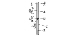
外周フレーム32は、前面部32a(図8A参照)と、背面部32bと、側面部32cとを有している。前面部32aは、本体2の表示面2a側に、表示面2aの外周に沿って枠状に形成されている。背面部32bは、本体2の表示面2aとは反対側の背面側に枠状に形成されており、前面部32aと間隙を介して対向するように位置している。側面部32cは、前面部32aと背面部32bとを互いの最外周で連結し、フレームの最外周を構成している。本実施形態では、案内溝11は、外周フレーム32の背面部32bに設けられており、取付面としての壁面P(図8B参照)に取り付けた吊り下げピン21が案内溝11に嵌挿されるようになっている。
案内溝11の第1の係合部12は、背面部32bにおける表示面2aの長手方向に沿った2つの長手部32b1・32b2の一方(例えば長手部32b1)において、上記長手方向の中央に位置している。また、第2の係合部13は、背面部32における表示面2aの短手方向に沿った2つの短手部32b3・32b4の一方(例えば短手部32b3)において、上記短手方向の中央に位置している。連結溝14は、背面部32の長手部32b1および短手部32b3に設けられて、第1の係合部12と第2の係合部13とを連結している。
第1の係合部12および第3の係合部13は、本体2の自重により、吊り下げピン21がそれぞれ横掛け状態(横長設置状態)、縦掛け状態(縦長設置状態)で引っ掛かる半円部で構成されている。
また、本実施形態では、外周フレーム32の側面部32cを構成する4つの面のうち、表示面2aの短手方向に延び、かつ、表示面2aに対して第2の係合部13の形成側とは反対側に位置する面には、挿入口17が形成されている。挿入口17は、吊り下げピン21が挿抜される開口であり、案内溝11の誘導溝16を介して、第1の係合部12と連結されている。これにより、挿入口17から挿入される吊り下げピン21は、誘導溝16を通り、第1の係合部12に向かって相対的に誘導される。
なお、挿入口17は、外周フレーム32の側面部32cを構成する4つの面のうち、表示面2aの長手方向に延び、かつ、表示面2aに対して第1の係合部12の形成側とは反対側に位置する面に設けられ、誘導溝を介して第2の係合部13と連結されていてもよい。この場合は、挿入口17から挿入された吊り下げピン21は、上記誘導溝を通り、第2の係合部13に向かって相対的に誘導されることになる。
図8Aは、本実施形態の表示装置1の横長設置状態での正面透視図であり、図8Bは、図8AのA-A’線での断面図であり、図8Cは、上記表示装置1の縦長設置状態での正面透視図である。また、図9Aは、表示装置1の横長設置状態から縦長設置状態への状態遷移を模式的に示す正面透視図であり、図9Bは、取付面である壁面Pに対する表示装置1の設置状態を示す断面図である。挿入口17に吊り下げピン21を挿入し、本体2を移動させることで、吊り下げピン21を案内溝11の誘導溝16を介して第1の係合部12まで相対的に移動させることができる。第1の係合部12の位置では、本体2の自重によって吊り下げピン21が第1の係合部12に引っ掛かることで本体2が静止し、本体2が横長設置状態で固定される。
本体2を横長設置状態から縦長設置状態に遷移させる場合には、吊り下げピン21が連結溝14を移動して第2の係合部13に到達するまで、本体2を移動(スライド、回転)させる。第2の係合部13の位置では、本体2の自重によって吊り下げピン21が第2の係合部13に引っ掛かることで本体2が静止し、本体2が縦長設置状態で固定される。
このように、吊り下げピン21の移動を案内するための案内溝11を、外周フレーム32に設けるようにしても、横長設置状態と縦長設置状態との間で設置状態を遷移させるとともに、従来のような回転機構や固定機構を設けることなく、回転や固定を実現できる。特に、外周フレーム32は、上述した前面部32aと、背面部32bと、側面部32cとを有しているので、本実施形態のように、背面部32bに案内溝11を設けて、壁面Pに取り付けた吊り下げピン21を案内溝11に嵌挿させることにより、図9Bに示すように、本体2を壁面Pに確実に近づけて配置して壁掛け設置を実現することができる。そして、表示装置1を壁面Pに近づけた状態で、横長設置状態と縦長設置状態との間で設置状態を遷移させることができる。
なお、案内溝11を側面部32cに形成すれば、吊り下げピン21を案内溝11に嵌挿させて壁面または天井からの吊り下げ設置を実現することができるが、この点については、後述の実施の形態5および6にて説明する。
また、案内溝11の第1の係合部12は、背面部32bの長手部32b1における表示面2aの長手方向の中央に位置しており、第2の係合部13は、背面部32bの短手部32b3における表示面2aの短手方向の中央に位置している。これにより、本体2の自重によって吊り下げピン21が第1の係合部13に引っ掛かったときに、表示装置1(本体2)をバランスよく保持して、横長設置状態で固定できる。同様に、本体2の自重によって吊り下げピン21が第2の係合部13に引っ掛かったときに、表示装置1をバランスよく保持して、縦長設置状態で固定できる。
また、前述の実施の形態1のように、設置時に吊り下げピン21を挿抜するための開口部15が裏面シャーシ2bに設けられている構成(図1B等参照)では、開口部15が表示面2aで隠れて見えないため、吊り下げピン21を開口部15に挿入する際に、開口部15のおおよその位置を表示面2a側から予測して挿入する必要がある。これに対して、本実施形態のように、吊り下げピン21を挿抜するための挿入口17が、外周フレーム32の側面部32cに設けられた構成では、吊り下げピン21を挿入口17に挿入する際に、横から目視で確認できるため、吊り下げピン21の挿入を確実にかつ容易に行うことができる。そして、挿入口17から挿入された吊り下げピン21を、誘導溝16によって第1の係合部12または第2の係合部13に誘導して、第1の係合部12と第2係合部13との間での本体2の移動による設置状態の遷移を行うことができる。
〔実施の形態5〕
本発明のさらに他の実施の形態について、図面に基づいて説明すれば、以下の通りである。
本発明のさらに他の実施の形態について、図面に基づいて説明すれば、以下の通りである。
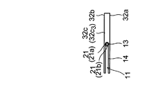
図10Aは、本実施形態の表示装置1の横長設置状態での正面図であり、図10Bは、上記表示装置1の横長設置状態での上面図であり、図10Cは、図10AにおけるA-A’線での断面図であり、図10Dは、上記表示装置1の縦長設置状態での正面図であり、図10Eは、上記表示装置1の縦長設置状態での上面図である。本実施形態では、案内溝11が、外周フレーム32の側面部32cに設けられており、取付面としての壁面Pに取り付けた吊り下げピン21が、図10Cのように折れ曲がった状態で案内溝11に嵌挿されるようにした点以外は、実施の形態4と同様の構成である。つまり、本実施形態では、表示装置1(本体2)は、壁面Pから吊り下げて設置される。
案内溝11の第1の係合部12は、側面部32cにおける表示面2aの長手方向に沿った2つの長手部32c1・32c2の一方(例えば長手部32c1)において、上記長手方向の中央に位置している。また、第2の係合部13は、側面部32cにおける表示面2aの短手方向に沿った2つの短手部32c3・32c4の一方(例えば短手部32c3)において、上記短手方向の中央に位置している。第1の係合部12および第2の係合部13の開口幅は、それらを連結する連結溝14の幅よりも大きく形成されており、また、吊り下げピン21の挿入口と第1の係合部12(または第2の係合部13)とを連結する誘導溝16の幅よりも大きく形成されている。なお、上記挿入口は、側面部32cにおける他方の短手部32c4に形成されているものとする。また、連結溝14および誘導溝16の各開口幅は、吊り下げピン21の棒状部21aの径よりも大きく、頭部21bの径(最小径)よりも小さい。
図11は、本実施形態の表示装置1の横長設置状態から縦長設置状態への状態遷移を模式的に示す正面透視図である。外周フレーム32の側面部32cの挿入口(図示せず)に吊り下げピン21を挿入し、本体2を移動させることで、吊り下げピン21を案内溝11の誘導溝16を介して第1の係合部12まで相対的に移動させることができる。第1の係合部12の位置では、本体2の自重によって吊り下げピン21が第1の係合部12に引っ掛かることで本体2が静止し、本体2が横長設置状態で固定される。
本体2を横長設置状態から縦長設置状態に遷移させる場合には、本体2を浮かせて、吊り下げピン21と第1の係合部12との係合を解除し、吊り下げピン21が連結溝14を移動して第2の係合部13に到達するまで、本体2を移動(スライド、回転)させる。第2の係合部13の位置では、本体2の自重によって吊り下げピン21が第2の係合部13に引っ掛かることで本体2が静止し、本体2が縦長設置状態で固定される。
図12Aは、吊り下げピン21が第1の係合部12または第2の係合部13に引っ掛かる前の状態を示す断面図であり、図12Bおよび図12Cは、本体2の自重により、吊り下げピン21が第1の係合部12または第2の係合部13に引っ掛かった状態での断面図および上面図である。吊り下げピン21の頭部21bは、棒状部21aとの連結側とは反対側に向かって径が段階的または連続的に増大する形状である。本実施形態では、頭部21bは、小径部21b1と大径部21b2とが連結されて構成されており、棒状部21aとの連結側とは反対側に向かって径が段階的に増大している。
案内溝11は、吊り下げピン21の頭部21bが嵌る溝形状であり、第1の係合部12および第2の係合部13は、頭部21bの最小径である小径部21b1の径よりも大きく、最大径である大径部21b2の径よりも小さい径の開口部でそれぞれ形成されている。
上記の構成において、本体2の移動によって吊り下げピン21が第1の係合部12の位置にきたとき、本体2が自重によって下降すると、吊り下げピン21は相対的に上昇し、吊り下げピン21の頭部21bの一部(小径部21b1)が第1の係合部12(開口部)に嵌ると同時に、頭部21bの残り(大径部21b2)が上記開口部の外側に引っ掛かる。これにより、吊り下げピン21に対する本体2の相対的な移動が規制されることになり、表示装置1が横長設置状態で固定される。
また、本体2の移動によって吊り下げピン21が第2の係合部13の位置にきたとき、本体2が自重によって下降すると、吊り下げピン21は相対的に上昇し、吊り下げピン21の頭部21bの一部(小径部21b1)が第2の係合部13(開口部)に嵌ると同時に、頭部21bの残り(大径部21b2)が上記開口部の外側に引っ掛かる。これにより、吊り下げピン21に対する本体2の相対的な移動が規制されることになり、表示装置1が縦長設置状態で固定される。
本実施形態のように、案内溝11が外周フレーム32の側面部32cに設けられて、壁面Pに取り付けたL字形の吊り下げピン21が案内溝11に嵌挿される構成であっても、横長設置状態と縦長設置状態との間で表示装置1の設置状態を遷移させることができる。また、従来のような回転機構や固定機構は不要なので、図12Aおよび図12Bに示すように、本体2を壁面Pに近づけて配置することができる。
また、第1の係合部12および第2の係合部13は、吊り下げピン21の頭部21bの最小径よりも大きく、最大径よりも小さい径の開口部でそれぞれ形成されているので、上述のように、吊り下げピン21が第1の係合部12または第2の係合部13の位置にあるときに、吊り下げピン21の頭部21bの一部を第1の係合部12または第2の係合部13の開口部に嵌めて、本体2の移動を規制することができる。これにより、表示装置1を横長設置状態または縦長設置状態で確実に固定することができる。
〔実施の形態6〕
本発明のさらに他の実施の形態について、図面に基づいて説明すれば、以下の通りである。
本発明のさらに他の実施の形態について、図面に基づいて説明すれば、以下の通りである。
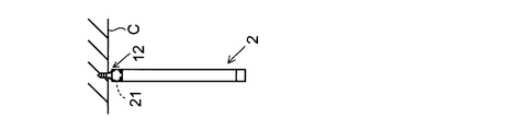
図13Aは、本実施形態の表示装置1の横長設置状態での正面図であり、図13Bは、上記表示装置1の横長設置状態での上面図であり、図13Cは、図13AにおけるA-A’線での断面図であり、図13Dは、上記表示装置1の縦長設置状態での正面図であり、図13Eは、上記表示装置1の縦長設置状態での上面図である。本実施形態では、吊り下げピン21を取付面としての天井Cに取り付けて、その吊り下げピン21を案内溝11に嵌挿するようにした以外は、実施の形態5と同様の構成である。つまり、本実施形態では、実施の形態5の表示装置1を、吊り下げピン21を介して天井Cから吊り下げて設置するようにしたものである。なお、吊り下げピン21の棒状部21aは、直線状に形成されており、実施の形態5のように折り曲げられていないものとする。
なお、本実施形態のように、表示装置1を天井Cから吊り下げて設置する場合でも、表示面が横長となるような設置状態を横長設置状態とし、表示面が縦長となるような設置状態を縦長設置状態とする。
案内溝11が外周フレーム32の側面部32cに設けられている構成において、天井Cに取り付けた吊り下げピン21を案内溝11に挿入し、案内溝11に沿って吊り下げピン21を相対的に移動させることにより、横長設置状態と縦長設置状態との間で表示装置1の設置状態を遷移させることができる。なお、このときの設置状態の遷移の様子は、図11で示した実施の形態5と同様である(取付面が壁面Pか天井Cかで異なるだけである)。
また、案内溝11に沿って吊り下げピン21を相対的に移動させることにより、案内溝11のどこかの位置を回転中心として本体2を回転させることができる。つまり、案内溝11において表示面2aの中心からずれた位置を回転中心として、本体2を回転させることができる。したがって、表示装置1(本体2)を天井Cに近づけて設置しても、本体2の回転によって横長設置状態と縦長設置状態との間で表示装置1の設置状態を遷移させることができ、表示装置1を天井Cに近づけて回転可能に設置することができる。
なお、断面L字形の吊り下げピン21を用いれば、実施の形態1~4で示した表示装置1を、天井Cから吊り下げて回転可能に設置することも可能である。
なお、以上では、表示装置1として、LCDやPDPを想定した例について説明したが、このほかにも、LED(Light Emitting Diode)や有機EL(Electro Luminescence)を用いた表示装置など、壁掛け設置や吊り下げ設置が可能な薄型の表示装置であれば上述した各実施の形態の構成を適用することができ、これによって各実施の形態と同様の効果を得ることができる。
なお、各実施の形態で説明した表示装置は、以下のように表現することができる。
上記表示装置は、矩形状の表示面を本体に備え、前記表示面が横長または縦長となるように取付面に設置されるとともに、前記本体を回転させることによって、横長設置状態と縦長設置状態との間で設置状態が遷移する薄型の表示装置であって、前記本体には、前記取付面に取り付けた吊り下げピンが嵌挿される案内溝が設けられており、前記案内溝は、前記横長設置状態において、前記本体の自重によって前記吊り下げピンが引っ掛かることで、前記本体の回転位置を前記横長設置状態の位置で固定する第1の係合部と、前記縦長設置状態において、前記本体の自重によって前記吊り下げピンが引っ掛かることで、前記本体の回転位置を前記縦長設置状態の位置で固定する第2の係合部と、前記第1の係合部と前記第2の係合部とを連結する連結溝とを有している構成である。
上記構成によれば、第1の係合部と第2の係合部との間を連結溝を介して吊り下げピンが相対的に移動するように本体を移動(回転も含む)させることにより、本体を横長設置状態と縦長設置状態との間で遷移させることができる。しかも、吊り下げピンが第1の係合部または第2の係合部と引っ掛かることで、横長設置状態、縦長設置状態のそれぞれにおいて本体の位置を固定できる。これにより、取付面が例えば壁面であれば、本体と壁面との間に従来のような回転機構や固定機構を設けることなく、本体(表示装置)を壁面に近づけて設置することができる。
また、案内溝に沿って吊り下げピンを相対的に移動させることにより、案内溝のどこかの位置を回転中心として本体を回転させることができ、例えば案内溝において表示面の中心からずれた位置を回転中心として、本体を回転させることができる。したがって、取付面が例えば天井である場合において、本体を天井に近づけて設置しても、回転によって横長設置状態と縦長設置状態との間で設置状態を遷移させることができる。
つまり、上記構成によれば、表示装置を取付面(壁面や天井)に近づけて設置できるとともに、取付面に近い位置でも、回転により横長設置状態と縦長設置状態との間で設置状態を遷移させ、かつ、その位置を固定することができる。
前記案内溝は、前記本体における前記表示面とは反対側の裏面シャーシに設けられており、前記取付面としての壁面に取り付けた前記吊り下げピンが前記案内溝に嵌挿される構成であってもよい。案内溝が裏面シャーシに設けられて壁掛け設置を行う場合に、上述の効果を得ることができる。
前記第1の係合部は、矩形状の前記裏面シャーシの中心よりも前記裏面シャーシの一方の長辺側で、かつ、長辺に沿った方向の中央に位置しており、前記第2の係合部は、矩形状の前記裏面シャーシの中心よりも前記裏面シャーシの一方の短辺側で、かつ、短辺に沿った方向の中央に位置していてもよい。
この場合、本体の自重によって吊り下げピンが第1の係合部に引っ掛かったときに、本体を壁面に対して右下がりや左下がりに傾かせることなく、バランスよく保持して、本体の回転位置を横長設置状態の位置で確実に固定することができる。また、本体の自重によって吊り下げピンが第2の係合部に引っ掛かったときに、本体を壁面に対して右下がりや左下がりに傾かせることなく、バランスよく保持して、本体の回転位置を縦長設置状態の位置で確実に固定することができる。
上記表示装置は、矩形状の表示面を本体に備え、壁面に設置されるとともに、前記表示面が横長となる横掛け状態(横長設置状態とも称する)と前記表示面が縦長となる縦掛け状態(縦長設置状態とも称する)との間で状態が遷移する薄型の表示装置であって、前記本体における前記表示面とは反対側の裏面シャーシには、壁面に取り付けた吊り下げピンが嵌挿される案内溝が設けられており、前記案内溝は、前記横掛け状態において、前記本体の自重によって前記吊り下げピンが引っ掛かることで、前記壁面に沿った面内での前記本体の回転位置を前記横掛け状態の位置で固定する第1の係合部と、前記縦掛け状態において、前記本体の自重によって前記吊り下げピンが引っ掛かることで、前記壁面に沿った面内での前記本体の回転位置を前記縦掛け状態の位置で固定する第2の係合部と、前記第1の係合部と前記第2の係合部とを連結する連結溝とを有していてもよい。
上記の構成によれば、表示装置の本体の裏面シャーシの案内溝に吊り下げピンを嵌挿した状態で本体を移動させることにより、本体を横掛け状態と縦掛け状態との間で遷移させることができる。つまり、吊り下げピンが第1の係合部に引っ掛かる位置では、本体を横掛け状態にすることができ、吊り下げピンが第2の係合部に引っ掛かる位置では、本体を縦掛け状態にすることができ、吊り下げピンが第1の係合部と第2の係合部との間の連結溝を通過するように本体を移動(スライド、回転)させることにより、本体を横掛け状態から縦掛け状態、または縦掛け状態から横掛け状態に遷移させることができる。したがって、そのような遷移を実現するに際して、本体と壁面との間に、本体を回転させるための厚みのある回転機構を設ける必要がなくなる。
また、横掛け状態では、本体の自重によって吊り下げピンが第1の係合部に引っ掛かることで、壁面に沿った面内での本体の回転位置が横掛け状態の位置で固定され、縦掛け状態では、本体の自重によって吊り下げピンが第2の係合部に引っ掛かることで、壁面に沿った面内での本体の回転位置が縦掛け状態の位置で固定されるので、本体の位置を横掛け状態および縦掛け状態で固定するための別途の固定機構を、本体と壁面との間に設ける必要もなくなる。
このように、上記構成によれば、本体と壁面との間に厚みのある回転機構や固定機構を設けることなく、本体の回転(横掛け状態と縦掛け状態との間での遷移)や所定の位置での固定を実現することができ、本体を壁面に近づけての壁掛け配置を実現することができる。
前記第1の係合部は、前記横長設置状態において、前記裏面シャーシの中心を通る鉛直線上で、前記中心よりも上方となる位置に設けられており、前記第2の係合部は、前記縦長設置状態において、前記裏面シャーシの中心を通る鉛直線上で、前記中心よりも上方となる位置に設けられていてもよい。また、前記第1の係合部は、矩形状の前記裏面シャーシの中心を通る、前記裏面シャーシの短辺に平行な直線上で、前記中心よりも前記横長設置状態で上方となる長辺側に位置しており、前記第2の係合部は、矩形状の前記裏面シャーシの中心を通る、前記裏面シャーシの長辺に平行な直線上で、前記中心よりも前記縦長設置状態で上方となる短辺側に位置していてもよい。
この場合、本体の自重によって吊り下げピンが第1の係合部に引っ掛かったときに、本体を壁面に対して右下がりや左下がりに傾かせることなく、バランスよく保持して、本体の回転位置を横長設置状態の位置で確実に固定することができる。また、本体の自重によって吊り下げピンが第2の係合部に引っ掛かったときに、本体を壁面に対して右下がりや左下がりに傾かせることなく、バランスよく保持して、本体の回転位置を縦長設置状態の位置で確実に固定することができる。
前記連結溝は、単一の直線状に形成されていてもよい。この場合、案内溝の簡単な構成で、つまり、第1の係合部と第2の係合部とを単一の直線状の連結溝で連結するという簡単な構成で、本体の横長設置状態と縦長設置状態との間での状態遷移を実現することができる。
前記連結溝は、前記裏面シャーシの外周に向かって凸となる曲線部と、該曲線部の一方の端部と前記第1の係合部とを前記裏面シャーシの外周に沿って直線状に連結する第1の直線部と、該曲線部の他方の端部と前記第2の係合部とを前記裏面シャーシの外周に沿って直線状に連結する第2の直線部とで構成されていてもよい。
第1の直線部および第2の直線部は、裏面シャーシの外周に沿って形成されており、それらを曲線部で連結しているので、本体を横長設置状態と縦長設置状態との間での遷移させるときに、横方向へのスライド、回転、横方向へのスライドという段階的な動作で遷移させることができる。つまり、本体が横長設置状態の位置から縦長設置状態の位置まで直線的に一気にスライドしないので、安全な状態遷移を実現することができる。
上記構成において、前記連結溝は、前記裏面シャーシの外周に向かって凸となる曲線状に形成されていてもよい。この構成では、連結溝が全体的に曲線状のため、本体が横長設置状態の位置と縦長設置状態の位置との間で少しでも直線的にスライドしない。したがって、より安全な状態遷移を実現することができる。
上記構成において、前記第1の係合部および前記第2の係合部は、前記連結溝の幅よりも大きい径の穴で形成されていてもよい。
この構成では、本体の移動により、吊り下げピンが連結溝から第1の係合部または第2の係合部の位置にきたときに、本体の自重によって吊り下げピンが第1の係合部または第2の係合部の穴に嵌って引っ掛かるため、横長設置状態または縦長設置状態で、吊り下げピンが第1の係合部または第2の係合部からずれるのを確実に回避することができる。その結果、本体の位置を横長設置状態または縦長設置状態で確実に固定することができる。
前記吊り下げピンは、前記壁面に固定される棒状部と、該棒状部よりも大径の頭部とを連結して構成されており、前記案内溝は、前記吊り下げピンが挿抜され、前記頭部よりも大きい径を持つ円形の開口部と、前記開口部に嵌挿された前記吊り下げピンを、前記第1の係合部または前記第2の係合部に向かって相対的に誘導するための誘導溝とをさらに有しており、前記案内溝の前記誘導溝、前記第1の係合部、前記第2の係合部および前記連結溝は、前記吊り下げピンの棒状部の径よりも大きく前記頭部の径よりも小さい開口幅を有し、かつ、前記吊り下げピンの前記頭部が嵌る溝形状で形成されていてもよい。
この場合、吊り下げピンの頭部を、開口部を除く案内溝の周囲の裏面シャーシで引っ掛けて、吊り下げピンが案内溝(開口部以外)から外れるのを防止しながら、本体を横長設置状態と縦長設置状態との間で遷移させることができる。また、吊り下げピンの案内溝への挿抜を、案内溝の開口部を介して行うことにより、本体の壁面への設置および取り外しを確実に行うことができる。
前記案内溝の前記開口部は、前記裏面シャーシの中心に位置していてもよい。この場合、案内溝の開口部のおおよその位置を表示面側から予測できるので、本体の壁面への設置時に、壁面に固定された吊り下げピンと案内溝の開口部とを位置合わせしながら、吊り下げピンを開口部に挿入することが容易となり、本体の壁面への設置を容易に行うことができる。
前記本体は、前記表示面を有する表示部本体と、前記表示部本体の外枠となる外周フレームとを有しており、前記案内溝は、前記外周フレームに設けられていてもよい。このように外周フレームの案内溝が設けられる構成であっても、横長設置状態と縦長設置状態との間で表示装置の設置状態を遷移させることができる。
前記外周フレームは、前記本体の前記表示面側に枠状に形成される前面部と、前記本体の前記表示面とは反対側の背面側に枠状に形成されて、前記前面部と間隙を介して対向する背面部と、前記前面部と前記背面部とを互いの最外周で連結する側面部とを有していてもよい。
この場合、案内溝を例えば背面部に形成すれば、取付面に固定された吊り下げピンを案内溝に嵌挿させて壁掛け設置を実現することができる。また、案内溝を例えば側面部に形成すれば、吊り下げピンを案内溝に嵌挿させて壁面または天井からの吊り下げ設置を実現することができる。
前記案内溝は、前記背面部に設けられており、前記取付面としての壁面に取り付けた前記吊り下げピンが前記案内溝に嵌挿されてもよい。この場合、壁面に取り付けた吊り下げピンを、背面部の案内溝に嵌挿させることで、表示装置を壁面に近づけた状態で、横長設置状態と縦長設置状態との間で設置状態を遷移させることができる。
前記第1の係合部は、前記背面部における前記表示面の長手方向に沿った2つの長手部の一方において、前記長手方向の中央に位置しており、前記第2の係合部は、前記背面部における前記表示面の短手方向に沿った2つの短手部の一方において、前記短手方向の中央に位置していてもよい。
この場合、本体の自重によって吊り下げピンが第1の係合部に引っ掛かったときに、本体を壁面に対して右下がりや左下がりに傾かせることなく、バランスよく保持して、本体の回転位置を横長設置状態の位置で確実に固定することができる。また、本体の自重によって吊り下げピンが第2の係合部に引っ掛かったときに、本体を壁面に対して右下がりや左下がりに傾かせることなく、バランスよく保持して、本体の回転位置を縦長設置状態の位置で確実に固定することができる。
前記外周フレームの前記側面部には、前記吊り下げピンが挿抜される挿入口が形成されており、前記背面部には、前記挿入口から挿入された前記吊り下げピンを前記第1の係合部または前記第2の係合部に相対的に誘導するための誘導溝が形成されていてもよい。
この構成では、吊り下げピンの挿入口への挿入を横から目視で確認できるので、吊り下げピンの挿入を確実にかつ容易に行うことができる。そして、挿入口から挿入された吊り下げピンを、誘導溝を介して第1の係合部または第2の係合部に誘導して、横長設置状態と縦長設置状態との間での設置状態の遷移を行うことができる。
前記案内溝は、前記側面部に設けられており、前記取付面としての壁面または天井に取り付けた前記吊り下げピンが前記案内溝に嵌挿されてもよい。この場合、壁面または天井に取り付けた吊り下げピンを、側面の案内溝に嵌挿させることで、表示装置を壁面または天井に近づけた状態で、横長設置状態と縦長設置状態との間で設置状態を遷移させることができる。
前記第1の係合部は、前記側面部における前記表示面の長手方向に沿った2つの長手部の一方において、前記長手方向の中央に位置しており、前記第2の係合部は、前記側面部における前記表示面の短手方向に沿った2つの短手部の一方において、前記短手方向の中央に位置していてもよい。
この場合、本体の自重によって吊り下げピンが第1の係合部に引っ掛かったときに、本体を壁面に対して右下がりや左下がりに傾かせることなく、バランスよく保持して、本体の回転位置を横長設置状態の位置で確実に固定することができる。また、本体の自重によって吊り下げピンが第2の係合部に引っ掛かったときに、本体を壁面に対して右下がりや左下がりに傾かせることなく、バランスよく保持して、本体の回転位置を縦長設置状態の位置で確実に固定することができる。
前記吊り下げピンは、前記取付面に固定される棒状部と、該棒状部よりも大径の頭部とを連結して構成されており、前記頭部は、前記棒状部との連結側とは反対側に向かって径が増大する形状であり、前記案内溝は、前記吊り下げピンの前記頭部が嵌る溝形状であり前記第1の係合部および前記第2の係合部は、前記頭部の最小径よりも大きく、最大径よりも小さい径の開口部でそれぞれ形成されていてもよい。
案内溝に吊り下げピンの頭部を嵌めて表示装置(本体)を取付面(天井または壁面)から吊り下げる場合において、吊り下げピンが第1の係合部または第2の係合部の位置にあるときに、本体が自重によって下がると、吊り下げピンが相対的に上昇して、頭部の一部が第1の係合部または第2の係合部の開口部内に嵌り、両者が固定される。これにより、表示装置の位置を横長設置状態または縦長設置状態で確実に固定することができる。
本発明は、壁掛け設置や吊り下げ設置が可能な薄型の表示装置に利用可能である。
1 表示装置
2 本体
2a 表示面
2b 裏面シャーシ
11 案内溝
12 第1の係合部
13 第2の係合部
14 連結溝
14a 第1の直線部
14b 第2の直線部
14c 曲線部
15 開口部
16 誘導溝
21 吊り下げピン
21a 棒状部
21b 頭部
31 表示部本体
32 外周フレーム
32a 前面部
32b 背面部
32b1 長手部
32b2 短手部
32c 側面部
32c1 長手部
32c2 短手部
L1 短辺
L2 長辺
O 裏面シャーシの中心
P 壁面(取付面)
C 天井(取付面)
2 本体
2a 表示面
2b 裏面シャーシ
11 案内溝
12 第1の係合部
13 第2の係合部
14 連結溝
14a 第1の直線部
14b 第2の直線部
14c 曲線部
15 開口部
16 誘導溝
21 吊り下げピン
21a 棒状部
21b 頭部
31 表示部本体
32 外周フレーム
32a 前面部
32b 背面部
32b1 長手部
32b2 短手部
32c 側面部
32c1 長手部
32c2 短手部
L1 短辺
L2 長辺
O 裏面シャーシの中心
P 壁面(取付面)
C 天井(取付面)
Claims (19)
- 矩形状の表示面を本体に備え、前記表示面が横長または縦長となるように取付面に設置されるとともに、前記本体を回転させることによって、横長設置状態と縦長設置状態との間で設置状態が遷移する薄型の表示装置であって、
前記本体には、前記取付面に取り付けた吊り下げピンが嵌挿される案内溝が設けられており、
前記案内溝は、
前記横長設置状態において、前記本体の自重によって前記吊り下げピンが引っ掛かることで、前記本体の回転位置を前記横長設置状態の位置で固定する第1の係合部と、
前記縦長設置状態において、前記本体の自重によって前記吊り下げピンが引っ掛かることで、前記本体の回転位置を前記縦長設置状態の位置で固定する第2の係合部と、
前記第1の係合部と前記第2の係合部とを連結する連結溝とを有していることを特徴とする表示装置。 - 前記案内溝は、前記本体における前記表示面とは反対側の裏面シャーシに設けられており、前記取付面としての壁面に取り付けた前記吊り下げピンが前記案内溝に嵌挿されることを特徴とする請求項1に記載の表示装置。
- 前記第1の係合部は、矩形状の前記裏面シャーシの中心よりも前記裏面シャーシの一方の長辺側で、かつ、長辺に沿った方向の中央に位置しており、
前記第2の係合部は、矩形状の前記裏面シャーシの中心よりも前記裏面シャーシの一方の短辺側で、かつ、短辺に沿った方向の中央に位置していることを特徴とする請求項2に記載の表示装置。 - 前記第1の係合部は、前記横長設置状態において、前記裏面シャーシの中心を通る鉛直線上で、前記中心よりも上方となる位置に設けられており、
前記第2の係合部は、前記縦長設置状態において、前記裏面シャーシの中心を通る鉛直線上で、前記中心よりも上方となる位置に設けられていることを特徴とする請求項2に記載の表示装置。 - 前記第1の係合部は、矩形状の前記裏面シャーシの中心を通る、前記裏面シャーシの短辺に平行な直線上で、前記中心よりも前記横長設置状態で上方となる長辺側に位置しており、
前記第2の係合部は、矩形状の前記裏面シャーシの中心を通る、前記裏面シャーシの長辺に平行な直線上で、前記中心よりも前記縦長設置状態で上方となる短辺側に位置していることを特徴とする請求項2に記載の表示装置。 - 前記連結溝は、単一の直線状に形成されていることを特徴とする請求項3に記載の表示装置。
- 前記連結溝は、前記裏面シャーシの外周に向かって凸となる曲線部と、該曲線部の一方の端部と前記第1の係合部とを前記裏面シャーシの外周に沿って直線状に連結する第1の直線部と、該曲線部の他方の端部と前記第2の係合部とを前記裏面シャーシの外周に沿って直線状に連結する第2の直線部とで構成されていることを特徴とする請求項3に記載の表示装置。
- 前記連結溝は、前記裏面シャーシの外周に向かって凸となる曲線状に形成されていることを特徴とする請求項3に記載の表示装置。
- 前記第1の係合部および前記第2の係合部は、前記連結溝の幅よりも大きい径の穴で形成されていることを特徴とする請求項1に記載の表示装置。
- 前記吊り下げピンは、前記壁面に固定される棒状部と、該棒状部よりも大径の頭部とを連結して構成されており、
前記案内溝は、
前記吊り下げピンが挿抜され、前記頭部よりも大きい径を持つ円形の開口部と、
前記開口部に嵌挿された前記吊り下げピンを、前記第1の係合部または前記第2の係合部に向かって相対的に誘導するための誘導溝とをさらに有しており、
前記案内溝の前記誘導溝、前記第1の係合部、前記第2の係合部および前記連結溝は、前記吊り下げピンの棒状部の径よりも大きく前記頭部の径よりも小さい開口幅を有し、かつ、前記吊り下げピンの前記頭部が嵌る溝形状で形成されていることを特徴とする請求項2に記載の表示装置。 - 前記案内溝の前記開口部は、前記裏面シャーシの中心に位置していることを特徴とする請求項10に記載の表示装置。
- 前記本体は、前記表示面を有する表示部本体と、前記表示部本体の外枠となる外周フレームとを有しており、
前記案内溝は、前記外周フレームに設けられていることを特徴とする請求項1に記載の表示装置。 - 前記外周フレームは、
前記本体の前記表示面側に枠状に形成される前面部と、
前記本体の前記表示面とは反対側の背面側に枠状に形成されて、前記前面部と間隙を介して対向する背面部と、
前記前面部と前記背面部とを互いの最外周で連結する側面部とを有していることを特徴とする請求項12に記載の表示装置。 - 前記案内溝は、前記背面部に設けられており、前記取付面としての壁面に取り付けた前記吊り下げピンが前記案内溝に嵌挿されることを特徴とする請求項13に記載の表示装置。
- 前記第1の係合部は、前記背面部における前記表示面の長手方向に沿った2つの長手部の一方において、前記長手方向の中央に位置しており、
前記第2の係合部は、前記背面部における前記表示面の短手方向に沿った2つの短手部の一方において、前記短手方向の中央に位置していることを特徴とする請求項14に記載の表示装置。 - 前記外周フレームの前記側面部には、前記吊り下げピンが挿抜される挿入口が形成されており、
前記背面部には、前記挿入口から挿入された前記吊り下げピンを前記第1の係合部または前記第2の係合部に相対的に誘導するための誘導溝が形成されていることを特徴とする請求項15に記載の表示装置。 - 前記案内溝は、前記側面部に設けられており、前記取付面としての壁面または天井に取り付けた前記吊り下げピンが前記案内溝に嵌挿されることを特徴とする請求項13に記載の表示装置。
- 前記第1の係合部は、前記側面部における前記表示面の長手方向に沿った2つの長手部の一方において、前記長手方向の中央に位置しており、
前記第2の係合部は、前記側面部における前記表示面の短手方向に沿った2つの短手部の一方において、前記短手方向の中央に位置していることを特徴とする請求項17に記載の表示装置。 - 前記吊り下げピンは、前記取付面に固定される棒状部と、該棒状部よりも大径の頭部とを連結して構成されており、
前記頭部は、前記棒状部との連結側とは反対側に向かって径が増大する形状であり、
前記案内溝は、前記吊り下げピンの前記頭部が嵌る溝形状であり
前記第1の係合部および前記第2の係合部は、前記頭部の最小径よりも大きく、最大径よりも小さい径の開口部でそれぞれ形成されていることを特徴とする請求項18に記載の表示装置。
Applications Claiming Priority (2)
| Application Number | Priority Date | Filing Date | Title |
|---|---|---|---|
| JP2012162319 | 2012-07-23 | ||
| JP2012-162319 | 2012-07-23 |
Publications (1)
| Publication Number | Publication Date |
|---|---|
| WO2014017202A1 true WO2014017202A1 (ja) | 2014-01-30 |
Family
ID=49997018
Family Applications (1)
| Application Number | Title | Priority Date | Filing Date |
|---|---|---|---|
| PCT/JP2013/066183 Ceased WO2014017202A1 (ja) | 2012-07-23 | 2013-06-12 | 表示装置 |
Country Status (1)
| Country | Link |
|---|---|
| WO (1) | WO2014017202A1 (ja) |
Cited By (3)
| Publication number | Priority date | Publication date | Assignee | Title |
|---|---|---|---|---|
| JP2016101218A (ja) * | 2014-11-27 | 2016-06-02 | 祐介 西澤 | 展示用構造物 |
| JP2019219540A (ja) * | 2018-06-20 | 2019-12-26 | 株式会社リコー | ディスプレイ用スタンド及びディスプレイスタンドシステム |
| CN111031855A (zh) * | 2017-08-29 | 2020-04-17 | 乐高公司 | 悬挂物件 |
Citations (6)
| Publication number | Priority date | Publication date | Assignee | Title |
|---|---|---|---|---|
| JPS5574480U (ja) * | 1978-11-20 | 1980-05-22 | ||
| US4211022A (en) * | 1978-09-29 | 1980-07-08 | Nicholas Angelakos | Picture frame |
| JPH117250A (ja) * | 1997-06-13 | 1999-01-12 | Nec Home Electron Ltd | 薄型表示装置 |
| JP2003015541A (ja) * | 2001-06-29 | 2003-01-17 | Pioneer Electronic Corp | プラズマディスプレイパネル取付装置 |
| JP2004215180A (ja) * | 2003-01-08 | 2004-07-29 | Sanyo Electric Co Ltd | 携帯型無線端末機 |
| JP2010245711A (ja) * | 2009-04-03 | 2010-10-28 | Onkyo Corp | スピーカーキャビネット及びこれを用いたスピーカーシステム |
-
2013
- 2013-06-12 WO PCT/JP2013/066183 patent/WO2014017202A1/ja not_active Ceased
Patent Citations (6)
| Publication number | Priority date | Publication date | Assignee | Title |
|---|---|---|---|---|
| US4211022A (en) * | 1978-09-29 | 1980-07-08 | Nicholas Angelakos | Picture frame |
| JPS5574480U (ja) * | 1978-11-20 | 1980-05-22 | ||
| JPH117250A (ja) * | 1997-06-13 | 1999-01-12 | Nec Home Electron Ltd | 薄型表示装置 |
| JP2003015541A (ja) * | 2001-06-29 | 2003-01-17 | Pioneer Electronic Corp | プラズマディスプレイパネル取付装置 |
| JP2004215180A (ja) * | 2003-01-08 | 2004-07-29 | Sanyo Electric Co Ltd | 携帯型無線端末機 |
| JP2010245711A (ja) * | 2009-04-03 | 2010-10-28 | Onkyo Corp | スピーカーキャビネット及びこれを用いたスピーカーシステム |
Cited By (4)
| Publication number | Priority date | Publication date | Assignee | Title |
|---|---|---|---|---|
| JP2016101218A (ja) * | 2014-11-27 | 2016-06-02 | 祐介 西澤 | 展示用構造物 |
| CN111031855A (zh) * | 2017-08-29 | 2020-04-17 | 乐高公司 | 悬挂物件 |
| JP2019219540A (ja) * | 2018-06-20 | 2019-12-26 | 株式会社リコー | ディスプレイ用スタンド及びディスプレイスタンドシステム |
| JP7110752B2 (ja) | 2018-06-20 | 2022-08-02 | 株式会社リコー | ディスプレイ用スタンド及びディスプレイスタンドシステム |
Similar Documents
| Publication | Publication Date | Title |
|---|---|---|
| CN103185193B (zh) | 用于显示设备的支撑装置 | |
| EP2108180B1 (en) | Device mount with selectively positionable tilt axis | |
| EP3450815B1 (en) | Display apparatus | |
| CN101403937B (zh) | 支撑装置以及具有该支撑装置的双显示单元 | |
| JP2006195217A (ja) | 薄型表示装置用スタンド | |
| US8390996B2 (en) | Display device | |
| US20250138579A1 (en) | Display device | |
| CN1971765A (zh) | 显示器装置 | |
| WO2014017202A1 (ja) | 表示装置 | |
| JP6403384B2 (ja) | 支持フレーム及びこれを備えたディスプレイ装置 | |
| KR102897620B1 (ko) | 디스플레이 장치용 벽걸이 장치 | |
| JP2014041309A (ja) | 画像表示装置 | |
| JP2010019893A (ja) | モニタ位置調節装置 | |
| KR101488584B1 (ko) | 액정 패널 적재 카세트 | |
| KR20100039040A (ko) | 디스플레이 기기 | |
| KR101566027B1 (ko) | 디스플레이 기기의 지지 장치 | |
| JP2011149453A (ja) | 電子機器取付装置及び電子機器用取付ブラケット | |
| JP2006064786A (ja) | 液晶表示装置 | |
| JP2006296755A (ja) | 薄型ディスプレイ装置を備えた床頭台 | |
| KR101579311B1 (ko) | 디스플레이 장치 | |
| CN213177559U (zh) | 一种壁挂支架、壁挂组件和壁挂系统 | |
| JP2005173421A (ja) | フラット型ディスプレイ | |
| KR102893621B1 (ko) | 폴더블 디바이스용 힌지장치 | |
| KR100607207B1 (ko) | 벽걸이 각도 조절장치 | |
| JP2007310186A (ja) | 薄型表示装置 |
Legal Events
| Date | Code | Title | Description |
|---|---|---|---|
| 121 | Ep: the epo has been informed by wipo that ep was designated in this application |
Ref document number: 13822338 Country of ref document: EP Kind code of ref document: A1 |
|
| NENP | Non-entry into the national phase |
Ref country code: DE |
|
| 122 | Ep: pct application non-entry in european phase |
Ref document number: 13822338 Country of ref document: EP Kind code of ref document: A1 |
|
| NENP | Non-entry into the national phase |
Ref country code: JP |