WO2014017190A1 - 空調室内機 - Google Patents
空調室内機 Download PDFInfo
- Publication number
- WO2014017190A1 WO2014017190A1 PCT/JP2013/065993 JP2013065993W WO2014017190A1 WO 2014017190 A1 WO2014017190 A1 WO 2014017190A1 JP 2013065993 W JP2013065993 W JP 2013065993W WO 2014017190 A1 WO2014017190 A1 WO 2014017190A1
- Authority
- WO
- WIPO (PCT)
- Prior art keywords
- air
- flap
- indoor unit
- vertical
- conditioning indoor
- Prior art date
- Legal status (The legal status is an assumption and is not a legal conclusion. Google has not performed a legal analysis and makes no representation as to the accuracy of the status listed.)
- Ceased
Links
Images




Classifications
-
- F—MECHANICAL ENGINEERING; LIGHTING; HEATING; WEAPONS; BLASTING
- F24—HEATING; RANGES; VENTILATING
- F24F—AIR-CONDITIONING; AIR-HUMIDIFICATION; VENTILATION; USE OF AIR CURRENTS FOR SCREENING
- F24F13/00—Details common to, or for air-conditioning, air-humidification, ventilation or use of air currents for screening
- F24F13/08—Air-flow control members, e.g. louvres, grilles, flaps or guide plates
- F24F13/10—Air-flow control members, e.g. louvres, grilles, flaps or guide plates movable, e.g. dampers
- F24F13/14—Air-flow control members, e.g. louvres, grilles, flaps or guide plates movable, e.g. dampers built up of tilting members, e.g. louvre
- F24F13/1413—Air-flow control members, e.g. louvres, grilles, flaps or guide plates movable, e.g. dampers built up of tilting members, e.g. louvre using more than one tilting member, e.g. with several pivoting blades
-
- F—MECHANICAL ENGINEERING; LIGHTING; HEATING; WEAPONS; BLASTING
- F24—HEATING; RANGES; VENTILATING
- F24F—AIR-CONDITIONING; AIR-HUMIDIFICATION; VENTILATION; USE OF AIR CURRENTS FOR SCREENING
- F24F1/00—Room units for air-conditioning, e.g. separate or self-contained units or units receiving primary air from a central station
- F24F1/0007—Indoor units, e.g. fan coil units
- F24F1/0011—Indoor units, e.g. fan coil units characterised by air outlets
-
- F—MECHANICAL ENGINEERING; LIGHTING; HEATING; WEAPONS; BLASTING
- F24—HEATING; RANGES; VENTILATING
- F24F—AIR-CONDITIONING; AIR-HUMIDIFICATION; VENTILATION; USE OF AIR CURRENTS FOR SCREENING
- F24F1/00—Room units for air-conditioning, e.g. separate or self-contained units or units receiving primary air from a central station
- F24F1/0007—Indoor units, e.g. fan coil units
- F24F1/0043—Indoor units, e.g. fan coil units characterised by mounting arrangements
- F24F1/005—Indoor units, e.g. fan coil units characterised by mounting arrangements mounted on the floor; standing on the floor
Definitions
- the present invention relates to an air conditioning indoor unit.
- Patent Document 1 Japanese Patent Application Laid-Open No. 2006-064219 proposes a floor-standing air conditioning indoor unit in which air outlets are arranged vertically on both sides of a product.
- an object of the present invention is to provide an air conditioning indoor unit that has a beautiful appearance and can improve the wind direction adjustment performance.
- the air conditioning indoor unit is a floor-mounted air conditioning indoor unit, and includes a blowout port forming member, a first left / right airflow direction adjusting flap, and a second left / right airflow direction adjusting flap.
- a blower outlet formation member forms the blower outlet of conditioned air.
- the first left / right wind direction adjusting flap has a rotating shaft extending in the vertical direction, and adjusts the left / right wind direction of the conditioned air blown out from the air outlet.
- the first left / right airflow direction adjusting flap covers the vicinity of the left end of the air outlet in the closed state.
- the second left / right airflow direction adjusting flap has a rotating shaft extending in the vertical direction, and adjusts the left / right airflow direction of the conditioned air blown from the air outlet.
- the second left / right wind direction adjusting flap covers the vicinity of the right end of the air outlet in the closed state.
- Both flaps are opened by rotating to retract inward.
- the flap can be made larger with respect to the air outlet, so that the wind direction adjustment performance is improved and the opening is hidden behind the flap when stopped, and the appearance is beautiful.
- the air conditioning indoor unit according to the second aspect of the present invention is the air conditioning indoor unit according to the first aspect, and further includes a control unit.
- the control unit performs control so as to provide a time difference between the start of rotation of the first left / right air direction adjustment flap and the start of rotation of the second left / right air direction adjustment flap.
- the air conditioning indoor unit according to the third aspect of the present invention is the air conditioning indoor unit according to the second aspect, and further includes a casing member that forms a main body.
- a blower outlet formation member has a left-right inner wall part which forms the left-right inner wall of a blower outlet.
- the outer surface of the casing member is located outside the cool air progression space after blowing.
- the cool air advance space after blowing is a space on the front side from the virtual plane extending in the direction of the maximum left and right angle with respect to the front blowing direction of the left and right airflow direction adjustment flaps from the tips of the left and right inner wall portions.
- the cool air progressing space has a virtual plane extending from the left end of the left and right inner wall portions in the direction of the maximum left and right angle with respect to the front blowing direction of the first left and right airflow direction adjustment flap, and the right end of the right and left inner wall portions. 2 A space on the front side of the virtual plane extending in the direction of the maximum left-right angle with respect to the front blowing direction of the left / right airflow direction adjustment flap.
- An air conditioning indoor unit is the air conditioning indoor unit according to the third aspect, wherein the first left and right wind direction adjustment flaps and the second left and right wind direction adjustment flaps are closed at the front ends of the left and right inner wall portions.
- the first left and right wind direction adjusting flaps and the second left and right wind direction adjusting flaps are hidden behind. This produces an excellent aesthetic.
- the flap can be made larger than the air outlet, the wind direction adjustment performance is improved, and the opening is hidden behind the flap when stopped, and the appearance is beautiful.
- the air conditioner indoor unit according to the second aspect of the present invention an excellent aesthetic appearance is produced, and dust is prevented from entering the product when stopped.
- the air conditioning indoor unit according to the third aspect of the present invention it is possible to suppress the cold air from touching the casing surface and to suppress the dew condensation during the cooling operation.
- the air conditioning indoor unit according to the fourth aspect of the present invention produces an excellent aesthetic appearance.
- FIG. 5 is a VV cross-sectional view of FIG. 3. The figure similar to FIG. 5 which shows the locus
- FIG. 1 is a refrigerant circuit diagram of the air conditioner 100.
- the air conditioner 100 is capable of both cooling and heating, and is mainly composed of an air conditioner indoor unit 100a installed in the living room R and an air conditioner outdoor unit 100b installed outside the living room R. ing.
- the air conditioning indoor unit 100a includes an indoor heat exchanger 5 and a sirocco fan 31 (see FIG. 4).
- the air conditioning outdoor unit 100b includes a compressor 2, an outdoor heat exchanger 3, an expansion mechanism 4, a four-way switching valve 6, and a fan (not shown).
- the compressor 2 sucks and compresses a low-pressure refrigerant, and discharges it at a high pressure.
- the outdoor heat exchanger 3 functions as a condenser that condenses the refrigerant during the cooling operation, and functions as an evaporator that evaporates the refrigerant during the heating operation. Air that exchanges heat with the outdoor heat exchanger 3 is supplied by a fan.
- the expansion mechanism 4 depressurizes and expands the high-pressure refrigerant.
- the indoor heat exchanger 5 functions as an evaporator that evaporates the refrigerant during the cooling operation, and functions as a condenser that condenses the refrigerant during the heating operation. Air that exchanges heat with the indoor heat exchanger 5 is supplied by a sirocco fan 31.
- the four-way switching valve 6 switches the refrigerant flow between the cooling operation and the heating operation.
- the refrigerant pipe 12b extending from the indoor heat exchanger 5 is connected to the suction pipe 10a to the compressor 2, and the discharge pipe 10b from the compressor 2 is extended to the outdoor heat exchanger 3.
- the refrigerant pipe 11 a extending from the outdoor heat exchanger 3 is connected to the suction pipe 10 a to the compressor 2, and the discharge pipe 10 b from the compressor 2 is connected to the refrigerant pipe 12 b extending to the indoor heat exchanger 5.
- the compressor 2 is connected to the outdoor heat exchanger 3 via the four-way switching valve 6 by a discharge pipe 10b and a refrigerant pipe 11a.
- the outdoor heat exchanger 3 is connected to the expansion mechanism 4 by a refrigerant pipe 11b.
- the expansion mechanism 4 is connected to the indoor heat exchanger 5 by a refrigerant pipe 12a.
- the indoor heat exchanger 5 is connected to the compressor 2 via a four-way switching valve 6 by a refrigerant pipe 12b and a suction pipe 10a.
- left and right, front and rear, and top and bottom mean the directions shown in FIG. That is, here, in the air conditioning indoor unit 100a, the front (front) is the front side (front side) where the air outlet E (see FIG. 4) to be described later is formed (the side from which the air that has passed through the indoor heat exchanger 5 blows out). And back).
- the upper and lower sides are represented with the side installed on the floor as the bottom. Further, left and right represent left and right in a state of facing front (front).
- FIG. 2 is an external perspective view of the air conditioning indoor unit 100a.
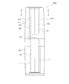
- FIG. 3 is a front view of the air conditioning indoor unit 100a.
- the air conditioning indoor unit 100a is a floor-standing type installed on the floor of the living room R.
- the air conditioner indoor unit 100a has a shape that is long in the height direction (vertical direction), and gradually decreases in width from the center in the height direction to each of the upper part and the lower part, as in entasis.
- the outer surface, that is, the main body of the air conditioning indoor unit 100 a is formed by the casing member 21.
- the casing member 21 is made of resin, and mainly includes a front cover that covers the front surface from the front surface and a back cover 21b that covers the rear surface from the side surface.
- the front cover further includes a plurality of parts such as a front upper panel 21a, a front lower panel 21c, and a lower panel cover 23.
- the front upper panel 21a covers from the upper side surface to the front surface, and a vertically long rectangular hole for the air outlet E is formed at the center in the width direction of the front surface.
- the front lower panel 21c covers from the lower side surface to the front surface, and a vertically long rectangular hole for the suction port I is formed at the center in the width direction of the front surface.
- the front lower panel 21c has holes for the suction ports I formed in a lattice shape at portions corresponding to both side surfaces.
- the lower panel cover 23 covers the front of the hole formed as the suction port I at the center in the width direction at the lower part of the front surface.
- a gap is formed between both ends in the width direction of the lower panel cover 23 and the front lower panel 21c. This gap serves as a suction port I for taking air in the living room into the air conditioning indoor unit 100a.
- Two vertical flaps 22 that are long in the height direction are provided above the central portion in the height direction in the front surface of the air conditioning indoor unit 100a.
- FIG. 4 is a front view of the air conditioning indoor unit 100a with the front lower panel 21c, the lower panel cover 23, and the vertical flap 22 removed. As shown in FIG.
- the sirocco fan 31 is provided below the central portion in the height direction of the air conditioning indoor unit 100 a and is positioned behind the lower panel cover 23 and the suction port I.
- the sirocco fan 31 sucks the air in the living room R into the air conditioning indoor unit 100a. The sucked air moves upward in the air conditioning indoor unit 100a.
- the air that has exchanged heat with the refrigerant when passing through the indoor heat exchanger 5 is blown out into the living room R from the air outlet E.
- the blower outlet E is provided above the center part in the height direction of the front surface of the air conditioning indoor unit 100a.
- the air outlet E has a rectangular shape that is long in the height direction, and is an opening from the inside of the air conditioning indoor unit 100a to the living room R.
- the air outlet E is formed by the air outlet forming member 40.
- the indoor heat exchanger 5 is disposed in the back of the air outlet E, and a horizontal flap 24 is provided in front of the indoor heat exchanger 5.
- a vertical flap 22 is provided in front of the horizontal flap 24.
- Horizontal flap A plurality of the horizontal flaps 24 are provided in the outlet E side by side in the height direction.
- Each of the plurality of horizontal flaps 24 is supported by a rotation shaft extending in the horizontal direction, and is configured to tilt in the vertical direction when driven and rotated by an actuator (not shown).
- the plurality of horizontal flaps 24 adjust the air direction from the outlet E in the vertical direction by the inclination in the vertical direction.
- the vertical flap 22 is provided with a left first vertical flap 22a and a right second vertical flap 22b.
- the two vertical flaps 22 are each supported by a rotating shaft 62 extending in the vertical direction, and are configured to be tilted separately in the left-right direction by being driven and rotated by an actuator (not shown). .
- the vertical flap 22 adjusts the wind direction in the left-right direction by the inclination in the left-right direction. That is, the first vertical flap 22a and the right second vertical flap 22b rotate around the rotation shaft 62 extending around the vertical direction and adjust the wind direction in the left-right direction of the conditioned air blown from the outlet E. .
- the two vertical flaps 22 are configured to be in a closed state in which the air outlet E is closed when air is not blown out from the air outlet E. That is, in the closed state, as shown in FIGS. 3 and 5, the first vertical flap 22a covers the left half including the vicinity of the left end of the outlet E, and the second vertical flap 22b is in the vicinity of the right end of the outlet E. It is comprised so that the right half containing a part may be covered.
- the air outlet E is hidden behind the vertical flap 22 and cannot be seen from outside.
- the vertical flap 22 rotates inward from the closed state, and the air outlet E is in an open state where the appearance is visible. Specifically, the left first vertical flap 22a rotates so that its left end moves forward and its right end moves backward. The second vertical flap 22b on the right side rotates so that its right end moves forward and its left end moves backward. In this open state, the air that has passed through the indoor heat exchanger 5, that is, conditioned air, can be blown out from the outlet E into the room R.
- the control unit 50 is configured by a CPU or the like, and controls the air conditioning indoor unit 100a such as the inclination of the vertical flaps 22 and the horizontal flaps 24 and the rotation of the sirocco fan 31.
- the control unit 50 rotates the two vertical flaps 22 inward from the closed state to the open state. That is, as described above, the control unit 50 rotates the left first vertical flap 22a so that the left end moves forward and the right end moves rearward, and the closed first vertical flap 22a is moved. Leave it open. Further, the control unit 50 rotates the second vertical flap 22b on the right side so that the right end thereof moves forward and the left end thereof moves rearward, and the closed second vertical flap 22b is opened.
- the control unit 50 determines whether the first vertical flap 22a rotates.
- the rotation timing of the vertical flap 22b is made different. Since there is almost no gap between the first vertical flap 22a and the second vertical flap 22b, the trajectory T1 of the rotation of the right end of the first vertical flap 22a and the rotation of the left end of the second vertical flap 22b as shown in FIG. It intersects with the movement trajectory T2. Therefore, if both vertical flaps 22a and 22b are rotated at the same timing, the first vertical flap 22a and the second vertical flap 22b collide.
- the first vertical flap 22a and the second vertical flap 22b can be prevented from colliding by shifting the rotation timing of the first vertical flap 22a and the rotation timing of the second vertical flap 22b. .
- interval of the 1st vertical flap 22a and the 2nd vertical flap 22b in a closed state can be narrowed (a clearance gap is made small), and even if the space
- the distance between the first vertical flap 22a and the second vertical flap 22b in the closed state is increased, not only an excellent aesthetic appearance is produced, but also the entry of foreign matter such as dust into the air outlet E can be suppressed.
- the air outlet forming member 40 is a resin member, and forms the rectangular air outlet E that is long in the height direction as described above.
- the blower outlet forming member 40 has left and right inner wall parts 41 that form the left and right inner walls of the blower outlet E, and upper and lower inner wall parts 42 that form the upper and lower inner walls of the blower outlet E.
- the air outlet forming member 40 is a member different from the casing member 21. For this reason, even if the blower outlet forming member 40 is cooled by cold air, the cold temperature is hardly transmitted to the casing member 21. Steps with respect to the front blowing direction are formed on the left and right surfaces of the left and right inner wall portions 41. Specifically, as shown in FIG.
- the front end 41 a of the left and right inner wall portions 41 protrudes forward from the outer surface of the adjacent casing member 21 (front upper panel 21 a), and the air outlet E is forward. It has a surface extending obliquely in the left-right direction so as to spread in the left-right direction. That is, when the blower outlet E is viewed from the front, the left and right side walls are provided with steps (including an inclination) where the blower outlet E becomes narrower toward the back.
- a surface extending obliquely in the left-right direction of the tip 41a of the left and right inner wall portion 41 is configured to be parallel to the vertical flap 22 in a state at a maximum left-right angle ⁇ described later.
- the front end 41 a of the left and right inner wall portions 41 is hidden behind the vertical flap 22 and cannot be visually recognized. That is, when the vertical flap 22 is in the closed state, the front end 41a of the left and right inner wall portions 41 is hidden behind the first vertical flap 22a and the second vertical flap 22b.
- Cold Air Progression Space after Blowing is a space in which air (for example, cold air during cooling operation) after being blown out from the air outlet E travels.
- the blower outlet forming member 40, the casing member 21, and the vertical flap 22 are configured such that the outer surface of the casing member 21 is located outside the cool air progression space Z after blowing, and cold air is generated on the outer surface of the casing member 21. The contact is effectively suppressed.
- the above-described recess 21d is formed in the region of the surface of the casing member 21 close to the left and right inner side wall portions 41 of the air outlet forming member 40.
- the left and right tips 41 a of the left and right inner wall portions 41 have a structure that protrudes ahead of the outer surface of the casing member 21 to which the air outlet E is adjacent. .
- the dimension (D1 in FIG. 5) from the front end 41a of the left and right inner wall portions 41 to the most recessed portion of the outer surface of the casing member 21 forming the recess 21d, that is, the depth of the recess 21d is at least 10 mm. ing. Moreover, the distance (D2 of FIG. 5) from the part located most forward among the outer surfaces of the casing member 21 to the virtual surface A is at least 10 mm. That is, the casing member 21 is at least 10 mm away from the cool air progression space Z after blowing.
- the vertical flap 22 includes a virtual line in which the maximum left / right angle ⁇ , which is the maximum angle in the left / right direction with respect to the front blowing direction, includes a virtual line extending in the direction of the maximum left / right angle ⁇ from the tip 41a of the left / right inner wall portion 41 and spreads vertically.
- the casing member 21 is controlled so as to be located behind the virtual plane A.
- the after-blow-out cold progress space Z in which the cool air blown out from the blowout port E proceeds is located on the front side from the virtual plane A.
- the vertical flap 22 is inclined in the horizontal direction (the first vertical flap 22a is in the left direction and the second vertical flap 22b is in the right direction) with respect to the front blowing direction at a maximum horizontal angle ⁇ . Be controlled.
- the casing member 21 is located behind the virtual plane A extending in the vertical direction including the virtual line extending in the direction of the maximum left-right angle ⁇ from the tip 41a of the left and right inner side wall 41. That is, as shown in FIG. 5, the casing member 21 includes a virtual line extending from the left end 41 a of the left and right inner wall portion 41 to the left side by a maximum left-right angle ⁇ with respect to the front direction. It is located behind the expanding virtual plane A. Further, as shown in FIG.
- the casing member 21 includes a virtual line extending from the right end 41 a of the right and left inner wall portion 41 in a direction inclined rightward by the maximum left and right angle ⁇ with respect to the front direction. It is located behind the expanding virtual plane A.
- the after-blowing cool air progression space Z is located in front of these virtual planes A. Therefore, the outer surface of the casing member 21 is located outside the after-blow-out cool air progression space Z (a space outside the after-blow-out cool air progression space Z).
- the discharged refrigerant passes through the four-way switching valve 6, flows through the refrigerant pipe 11a, and flows to the outdoor heat exchanger 3.
- the refrigerant flowing into the outdoor heat exchanger 3 is cooled by exchanging heat with air, and then reaches the expansion mechanism 4 via the refrigerant pipe 11b.
- the refrigerant is decompressed and expanded by the expansion mechanism 4 and then flows into the indoor heat exchanger 5 via the refrigerant pipe 12a.
- the refrigerant takes heat from the air in the room R in the indoor heat exchanger 5 and becomes a superheated low-pressure gas refrigerant.
- the refrigerant that has become overheated low-pressure gas refrigerant passes through the four-way switching valve 6 via the refrigerant pipe 12b and flows to the suction pipe 10a.
- the air conditioning indoor unit 100a is a floor-standing type, and includes the air outlet forming member 40, the first vertical flap 22a, and the second vertical flap 22b.
- the blower outlet formation member 40 forms the blower outlet E of conditioned air.
- the first vertical flap 22a has its rotating shaft 62 extending in the vertical direction, and adjusts the left-right direction of the conditioned air blown out from the outlet E.
- the first vertical flap 22a covers the vicinity of the left end of the outlet E in the closed state.
- the second vertical flap 22b has a rotating shaft 62 extending in the vertical direction, and adjusts the right and left direction of the conditioned air blown out from the outlet E.
- the second vertical flap 22b covers the vicinity of the right end of the outlet E in the closed state.
- Both vertical flaps 22 are opened by rotating to retract inwardly.
- the vertical flap 22 can be made larger than the air outlet, so that the wind direction adjusting performance is improved and the air outlet E is hidden behind the vertical flap 22 when stopped, so that the appearance is beautiful.
- the control part 50 is further provided.
- the control unit 50 performs control so as to provide a time difference between the start of rotation of the first vertical flap 22a and the start of rotation of the second vertical flap 22b.
- the casing member 21 which forms a main body is further provided.
- the blower outlet forming member 40 includes left and right inner wall portions 41 that form the left and right inner walls of the blower outlet E.
- the outer surface of the casing member 21 is located outside the cool air progression space Z after blowing.
- the blown-out cool air progress space Z is a space on the front side from the virtual plane A extending in the direction of the maximum left-right angle ⁇ with respect to the front blowing direction of the vertical flap 22 from the tip 41a of the left and right inner wall portions 41.
- the after-blowing cool air progression space Z includes a virtual plane extending from the left end 41a of the left and right inner wall portion 41 in the direction of the maximum left and right angle ⁇ with respect to the front blowing direction of the first vertical flap 22a, and the right side of the left and right inner wall portion 41. This is a space on the front side of the imaginary plane extending in the direction of the maximum left-right angle ⁇ with respect to the front blowing direction of the second vertical flap 22b from the tip 41a.
- the air conditioning indoor unit 100a includes the two vertical flaps 22. However, in other embodiments, three or more vertical flaps 22 may be provided. Even in this case, the vertical flaps 22 positioned at both ends of the outlet E, that is, the first vertical flap 22a and the second vertical flap 22b may be rotated inward as described above so as to be in the open state. .
- the present invention is useful for an air-conditioning indoor unit capable of cooling operation.
- Casing member 21d Dimple 22 Vertical flap (left and right wind direction adjustment flap) 22a First vertical flap (first left and right wind direction adjustment flap) 22b Second vertical flap (second left / right wind direction adjustment flap) 40 Air outlet forming member 41 Left and right inner side wall parts 41a Tip 50 Control part 62 Rotating shaft 100a Air conditioning indoor unit A Virtual plane E Air outlet Z Cooling air advance space after blowing ⁇ Maximum left and right angle
Landscapes
- Engineering & Computer Science (AREA)
- Chemical & Material Sciences (AREA)
- Combustion & Propulsion (AREA)
- Mechanical Engineering (AREA)
- General Engineering & Computer Science (AREA)
- Air-Flow Control Members (AREA)
- Air Filters, Heat-Exchange Apparatuses, And Housings Of Air-Conditioning Units (AREA)
Abstract
外観が美しく、かつ、風向調整性能を向上することが可能な空調室内機。空調室内機(100a)は、床置型であって、吹出口形成部材(40)と、第1垂直フラップ(22a)と、第2垂直フラップ(22b)とを備える。吹出口形成部材(40)は、調和済空気の吹出口(E)を形成する。第1垂直フラップ(22a)および第2垂直フラップ(22b)は、その回動軸(62)が鉛直方向に延び、吹出口(E)より吹き出される調和済空気の左右方向の風向を調整する。第1垂直フラップ(22a)は、閉状態時に吹出口(E)の左端近傍部を覆う。第2垂直フラップ(22b)は、閉状態時に吹出口(E)の右端近傍部を覆う。開状態に移行するときに、第1垂直フラップ(22a)は、その左端が前方に移動し、その右端が後方に移動するように回動する。第2垂直フラップ(22b)は、その右端が前方に移動し、その左端が後方に移動するように回動する。
Description
本発明は、空調室内機に関する。
従来から、吹き出される空気の風向を左右方向に調整するフラップを備える空調室内機が提供されてきた。例えば、特許文献1(特開2006-064219号公報)には、吹出口を製品両サイドに縦長に配置した床置き型の空調室内機が提案されている。
ところで、特許文献1(特開2006-064219号公報)に記載の空調室内機では、運転時はフラップの製品中央側が製品前方に出るように回転させている。しかし、このようにフラップを製品中央側が前方に出るように回転させた場合、フラップの製品外側端部の回転軌跡が、吹出口端部と接触しないようにしなければならないため、フラップを大きくできず、風向調整性能が上げられない。また、吹出口端部との接触を回避しようとするとフラップに対して開口が大きくなる為、停止時の見た目も悪いという問題がある。
そこで、本発明の課題は、外観が美しく、かつ、風向調整性能を向上することが可能な空調室内機を提供することにある。
そこで、本発明の課題は、外観が美しく、かつ、風向調整性能を向上することが可能な空調室内機を提供することにある。
本発明の第1観点に係る空調室内機は、床置型の空調室内機であって、吹出口形成部材と、第1左右風向調整フラップと、第2左右風向調整フラップとを備える。吹出口形成部材は、調和済空気の吹出口を形成する。第1左右風向調整フラップは、その回動軸が鉛直方向に延び、吹出口より吹き出される調和済空気の左右方向の風向を調整する。第1左右風向調整フラップは、閉状態時に吹出口の左端近傍部を覆う。第2左右風向調整フラップは、その回動軸が鉛直方向に延び、吹出口より吹き出される調和済空気の左右方向の風向を調整する。第2左右風向調整フラップは、閉状態時に吹出口の右端近傍部を覆う。開状態に移行するときに、第1左右風向調整フラップは、その左端が前方に移動し、その右端が後方に移動するように回動する。第2左右風向調整フラップは、その右端が前方に移動し、その左端が後方に移動するように回動する。
両フラップは、内向きに引っ込むように回動することにより開く。これにより、吹出口に対して、フラップを大きく取れるため、風向調整性能がよくなると共に、停止時に開口部がフラップ背面に隠れる為、外観が美しい。
本発明の第2観点に係る空調室内機は、第1観点に係る空調室内機であって、制御部を更に備える。制御部は、第1左右風向調整フラップの回動の始動と第2左右風向調整フラップの回動の始動との間に時間差を設けるように制御する。
これにより、両フラップの中央部での回転軌跡が交差していても、フラップを開く事ができるため、両フラップ間の隙間をつめることができる。その結果、優れた美観を生ずるとともに、停止時に製品内部にゴミが侵入するのを抑えることができる。
これにより、両フラップの中央部での回転軌跡が交差していても、フラップを開く事ができるため、両フラップ間の隙間をつめることができる。その結果、優れた美観を生ずるとともに、停止時に製品内部にゴミが侵入するのを抑えることができる。
本発明の第3観点に係る空調室内機は、第2観点に係る空調室内機であって、本体を形成するケーシング部材をさらに備える。吹出口形成部材は、吹出口の左右内側壁を形成する左右内側壁部を有する。ケーシング部材の外表面は、吹出後冷気進行空間の外に位置する。吹出後冷気進行空間は、左右内側壁部の先端から左右風向調整フラップの正面吹き方向に対する最大左右角度の方向に延びる仮想面から前側の空間である。
つまり、吹出後冷気進行空間は、左右内側壁部の左側の先端から第1左右風向調整フラップの正面吹き方向に対する最大左右角度の方向に延びる仮想面と、左右内側壁部の右側の先端から第2左右風向調整フラップの正面吹き方向に対する最大左右角度の方向に延びる仮想面と、の前側の空間である。
これにより、ケーシング表面に冷気が触れるのを抑制し、冷房運転時における結露を抑制する。
これにより、ケーシング表面に冷気が触れるのを抑制し、冷房運転時における結露を抑制する。
本発明の第4観点に係る空調室内機は、第3観点に係る空調室内機であって、左右内側壁部の先端は、第1左右風向調整フラップおよび第2左右風向調整フラップが閉状態において、第1左右風向調整フラップおよび第2左右風向調整フラップの背後に隠れる。
これにより、優れた美観を生ずる。
これにより、優れた美観を生ずる。
本発明の第1観点に係る空調室内機では、吹出口に対して、フラップを大きく取れるため、風向調整性能がよくなると共に、停止時に開口部がフラップ背面に隠れる為、外観が美しい。
本発明の第2観点に係る空調室内機では、優れた美観を生ずるとともに、停止時に製品内部にゴミが侵入するのを抑える。
本発明の第3観点に係る空調室内機では、ケーシング表面に冷気が触れるのを抑制し、冷房運転時における結露を抑制する。
本発明の第4観点に係る空調室内機では、優れた美観を生ずる。
本発明の第2観点に係る空調室内機では、優れた美観を生ずるとともに、停止時に製品内部にゴミが侵入するのを抑える。
本発明の第3観点に係る空調室内機では、ケーシング表面に冷気が触れるのを抑制し、冷房運転時における結露を抑制する。
本発明の第4観点に係る空調室内機では、優れた美観を生ずる。
本発明の一実施形態に係る空調室内機である空調室内機100aについて、以下、図面を参照しながら説明する。
(1)空調機の全体構成
図1は、空調機100の冷媒回路図である。以下、空調機100の全体構成について図1を参照しながら説明する。
空調機100は、冷房と暖房との両方の運転が可能であり、主に居室R内に設置される空調室内機100aと、居室Rの外に設置される空調室外機100bと、から構成されている。空調室内機100aは、室内熱交換器5と、シロッコファン31(図4参照)とを有する。空調室外機100bは、圧縮機2、室外熱交換器3、膨張機構4、四路切替弁6、及び図示しないファンを有する。
(1)空調機の全体構成
図1は、空調機100の冷媒回路図である。以下、空調機100の全体構成について図1を参照しながら説明する。
空調機100は、冷房と暖房との両方の運転が可能であり、主に居室R内に設置される空調室内機100aと、居室Rの外に設置される空調室外機100bと、から構成されている。空調室内機100aは、室内熱交換器5と、シロッコファン31(図4参照)とを有する。空調室外機100bは、圧縮機2、室外熱交換器3、膨張機構4、四路切替弁6、及び図示しないファンを有する。
圧縮機2は、低圧の冷媒を吸入して圧縮し、高圧にして吐出する。
室外熱交換器3は、冷房運転時には、冷媒を凝縮させる凝縮器として機能し、暖房運転時には、冷媒を蒸発させる蒸発器として機能する。室外熱交換器3と熱交換する空気は、ファンにより供給される。
膨張機構4は、高圧の冷媒を減圧・膨張させる。
室内熱交換器5は、冷房運転時には、冷媒を蒸発させる蒸発器として機能し、暖房運転時には、冷媒を凝縮させる凝縮器として機能する。室内熱交換器5と熱交換する空気は、シロッコファン31により供給される。
四路切替弁6は、冷房運転時と暖房運転時とで、冷媒の流れを切り替える。具体的には、冷房運転時には、室内熱交換器5から延びる冷媒配管12bを圧縮機2への吸入配管10aに接続し、圧縮機2からの吐出管10bを室外熱交換器3へ延びる冷媒配管11aに接続する。暖房運転時には、室外熱交換器3から延びる冷媒配管11aを圧縮機2への吸入配管10aに接続し、圧縮機2からの吐出管10bを室内熱交換器5へ延びる冷媒配管12bに接続する。
室外熱交換器3は、冷房運転時には、冷媒を凝縮させる凝縮器として機能し、暖房運転時には、冷媒を蒸発させる蒸発器として機能する。室外熱交換器3と熱交換する空気は、ファンにより供給される。
膨張機構4は、高圧の冷媒を減圧・膨張させる。
室内熱交換器5は、冷房運転時には、冷媒を蒸発させる蒸発器として機能し、暖房運転時には、冷媒を凝縮させる凝縮器として機能する。室内熱交換器5と熱交換する空気は、シロッコファン31により供給される。
四路切替弁6は、冷房運転時と暖房運転時とで、冷媒の流れを切り替える。具体的には、冷房運転時には、室内熱交換器5から延びる冷媒配管12bを圧縮機2への吸入配管10aに接続し、圧縮機2からの吐出管10bを室外熱交換器3へ延びる冷媒配管11aに接続する。暖房運転時には、室外熱交換器3から延びる冷媒配管11aを圧縮機2への吸入配管10aに接続し、圧縮機2からの吐出管10bを室内熱交換器5へ延びる冷媒配管12bに接続する。
空調機100の冷媒回路では、図1に示すように、圧縮機2は、吐出管10b及び冷媒配管11aにより四路切替弁6を介して室外熱交換器3に接続されている。室外熱交換器3は、冷媒配管11bにより膨張機構4に接続されている。膨張機構4は、冷媒配管12aにより室内熱交換器5に接続されている。室内熱交換器5は、冷媒配管12b及び吸入管10aにより四路切替弁6を介して圧縮機2に接続されている。
(2)空調室内機の構成
図2~図6を参照しながら空調室内機100aの構成について説明する。なお、以下において、左右、前後、上下は、図2に示した方向を意味する。つまり、ここでは、空調室内機100aにおいて、後述する吹出口E(図4参照)が形成される側(室内熱交換器5を通過した空気が吹き出す側)を前(正面)として、前後(正面および背面)を表す。また、空調室内機100aにおいて、床に設置される側を下として、上下を表す。また、左右は、前(正面)を向いた状態での左右を表す。
(2)空調室内機の構成
図2~図6を参照しながら空調室内機100aの構成について説明する。なお、以下において、左右、前後、上下は、図2に示した方向を意味する。つまり、ここでは、空調室内機100aにおいて、後述する吹出口E(図4参照)が形成される側(室内熱交換器5を通過した空気が吹き出す側)を前(正面)として、前後(正面および背面)を表す。また、空調室内機100aにおいて、床に設置される側を下として、上下を表す。また、左右は、前(正面)を向いた状態での左右を表す。
(2-1)外観
図2は、空調室内機100aの外観斜視図である。図3は、空調室内機100aの正面図である。
空調室内機100aは、居室Rの床上に設置される床置型である。空調室内機100aは、高さ方向(鉛直方向)に長い形状をしており、エンタシスのように高さ方向中央部から上部及び下部それぞれにかけて徐々に幅が細くなっている。空調室内機100aの外表面、即ち本体は、ケーシング部材21により形成されている。
ケーシング部材21は、樹脂製であり、主に前面から側面を覆う前面カバーと側面から背面を覆う背面カバー21bとから構成されている。前面カバーは、さらに前面上部パネル21a、前面下部パネル21c、および下部パネルカバー23、等の複数のパーツから構成されている。
図2は、空調室内機100aの外観斜視図である。図3は、空調室内機100aの正面図である。
空調室内機100aは、居室Rの床上に設置される床置型である。空調室内機100aは、高さ方向(鉛直方向)に長い形状をしており、エンタシスのように高さ方向中央部から上部及び下部それぞれにかけて徐々に幅が細くなっている。空調室内機100aの外表面、即ち本体は、ケーシング部材21により形成されている。
ケーシング部材21は、樹脂製であり、主に前面から側面を覆う前面カバーと側面から背面を覆う背面カバー21bとから構成されている。前面カバーは、さらに前面上部パネル21a、前面下部パネル21c、および下部パネルカバー23、等の複数のパーツから構成されている。
前面上部パネル21aは、上部の側面から前面にかけて覆い、前面の幅方向中央には、吹出口Eのための鉛直に長い長方形の穴が形成されている。
前面下部パネル21cは、下部の側面から前面にかけて覆い、前面の幅方向中央には、吸込口Iのための鉛直に長い長方形の穴が形成されている。また、前面下部パネル21cには、両側面にあたる部分にも吸込口Iのための穴が格子状に形成されている。
下部パネルカバー23は、前面下部の幅方向中央の吸込口Iとして形成されている穴の前を覆う。下部パネルカバー23の幅方向両端と、前面下部パネル21cとの間には、隙間が形成されている。この隙間は、居室内の空気を空調室内機100aの内部に取り込む吸込口Iとなっている。
空調室内機100aの前面のうち高さ方向中央部より上方には、高さ方向に長い2枚の垂直フラップ22が設けられている。
前面下部パネル21cは、下部の側面から前面にかけて覆い、前面の幅方向中央には、吸込口Iのための鉛直に長い長方形の穴が形成されている。また、前面下部パネル21cには、両側面にあたる部分にも吸込口Iのための穴が格子状に形成されている。
下部パネルカバー23は、前面下部の幅方向中央の吸込口Iとして形成されている穴の前を覆う。下部パネルカバー23の幅方向両端と、前面下部パネル21cとの間には、隙間が形成されている。この隙間は、居室内の空気を空調室内機100aの内部に取り込む吸込口Iとなっている。
空調室内機100aの前面のうち高さ方向中央部より上方には、高さ方向に長い2枚の垂直フラップ22が設けられている。
2枚の垂直フラップ22の後方、即ち背面側には、室内熱交換器5を通過した空気が吹き出される吹出口Eが設けられている。
2枚の垂直フラップ22を合わせた幅と下部パネルカバー23の幅とは、同じであり、2枚の垂直フラップ22を合わせた左右両端と下部パネルカバー23の左右両端が揃うように構成されている。このため、優れた美観を生ずる。
前面上部パネル21aの吹出口Eに近接する部分には、窪み21dが設けられている。
(2-2)内部構造
図4は、前面下部パネル21c、下部パネルカバー23及び垂直フラップ22を外した状態の空調室内機100aの正面図である。
シロッコファン31は、図4に示されているように空調室内機100aの高さ方向の中央部より下方に設けられており、下部パネルカバー23及び吸込口Iの後方に位置する。シロッコファン31は、居室R内の空気を空調室内機100aの内部に吸い込む。吸い込まれた空気は、空調室内機100a内を上方に移動する。
2枚の垂直フラップ22を合わせた幅と下部パネルカバー23の幅とは、同じであり、2枚の垂直フラップ22を合わせた左右両端と下部パネルカバー23の左右両端が揃うように構成されている。このため、優れた美観を生ずる。
前面上部パネル21aの吹出口Eに近接する部分には、窪み21dが設けられている。
(2-2)内部構造
図4は、前面下部パネル21c、下部パネルカバー23及び垂直フラップ22を外した状態の空調室内機100aの正面図である。
シロッコファン31は、図4に示されているように空調室内機100aの高さ方向の中央部より下方に設けられており、下部パネルカバー23及び吸込口Iの後方に位置する。シロッコファン31は、居室R内の空気を空調室内機100aの内部に吸い込む。吸い込まれた空気は、空調室内機100a内を上方に移動する。
図5は、図3のV-V断面図である。
シロッコファン31により居室R内の空気を空調室内機100aの内部に吸い込まれた空気は、空調室内機100a内を上方に移動し、室内熱交換器5を通過する。室内熱交換器5を通過する際に冷媒と熱交換した空気は、吹出口Eから居室R内に吹き出される。
吹出口Eは、空調室内機100aの前面の高さ方向中央部より上方に設けられている。吹出口Eは、高さ方向に長い長方形の形状をしており、空調室内機100aの内部から居室Rへの開口である。吹出口Eは、吹出口形成部材40により形成されている。
図5に示すように吹出口Eの奥に室内熱交換器5が配置されており、その前方に水平フラップ24が設けられている。水平フラップ24の前方には、垂直フラップ22が設けられている。
シロッコファン31により居室R内の空気を空調室内機100aの内部に吸い込まれた空気は、空調室内機100a内を上方に移動し、室内熱交換器5を通過する。室内熱交換器5を通過する際に冷媒と熱交換した空気は、吹出口Eから居室R内に吹き出される。
吹出口Eは、空調室内機100aの前面の高さ方向中央部より上方に設けられている。吹出口Eは、高さ方向に長い長方形の形状をしており、空調室内機100aの内部から居室Rへの開口である。吹出口Eは、吹出口形成部材40により形成されている。
図5に示すように吹出口Eの奥に室内熱交換器5が配置されており、その前方に水平フラップ24が設けられている。水平フラップ24の前方には、垂直フラップ22が設けられている。
(2-3)水平フラップ
水平フラップ24は、吹出口E内に高さ方向に並んで複数設けられている。複数の水平フラップ24は、それぞれ水平方向に延びる回動軸により軸支されており、図示しないアクチュエータにより駆動されて回動することにより、上下方向に傾くように構成されている。複数の水平フラップ24は、当該上下方向の傾きにより吹出口Eからの風向を上下方向に調整する。
(2-4)垂直フラップ
垂直フラップ22は、左側の第1垂直フラップ22aと右側の第2垂直フラップ22bとの2つが設けられている。この2つの垂直フラップ22は、それぞれ鉛直方向に延びる回動軸62により軸支されており、図示しないアクチュエータにより駆動されて回動することにより、それぞれ別々に左右方向に傾くように構成されている。垂直フラップ22は、当該左右方向の傾きにより風向を左右方向に調整する。つまり、第1垂直フラップ22aと右側の第2垂直フラップ22bとは、鉛直方向周りに延びる回動軸62周りで回転し、吹出口Eより吹き出される調和済空気の左右方向の風向を調整する。2枚の垂直フラップ22は、吹出口Eから空気が吹き出されない場合は、吹出口Eを閉じた閉状態となるように構成されている。即ち、閉状態では、図3及び図5に示すように、第1垂直フラップ22aは、吹出口Eの左端近傍部を含む左半分を覆い、第2垂直フラップ22bは、吹出口Eの右端近傍部を含む右半分を覆うように構成されている。なお、2枚の垂直フラップ22が閉状態のとき、吹出口Eは、垂直フラップ22の背面側に隠れ外からは視認できない。
水平フラップ24は、吹出口E内に高さ方向に並んで複数設けられている。複数の水平フラップ24は、それぞれ水平方向に延びる回動軸により軸支されており、図示しないアクチュエータにより駆動されて回動することにより、上下方向に傾くように構成されている。複数の水平フラップ24は、当該上下方向の傾きにより吹出口Eからの風向を上下方向に調整する。
(2-4)垂直フラップ
垂直フラップ22は、左側の第1垂直フラップ22aと右側の第2垂直フラップ22bとの2つが設けられている。この2つの垂直フラップ22は、それぞれ鉛直方向に延びる回動軸62により軸支されており、図示しないアクチュエータにより駆動されて回動することにより、それぞれ別々に左右方向に傾くように構成されている。垂直フラップ22は、当該左右方向の傾きにより風向を左右方向に調整する。つまり、第1垂直フラップ22aと右側の第2垂直フラップ22bとは、鉛直方向周りに延びる回動軸62周りで回転し、吹出口Eより吹き出される調和済空気の左右方向の風向を調整する。2枚の垂直フラップ22は、吹出口Eから空気が吹き出されない場合は、吹出口Eを閉じた閉状態となるように構成されている。即ち、閉状態では、図3及び図5に示すように、第1垂直フラップ22aは、吹出口Eの左端近傍部を含む左半分を覆い、第2垂直フラップ22bは、吹出口Eの右端近傍部を含む右半分を覆うように構成されている。なお、2枚の垂直フラップ22が閉状態のとき、吹出口Eは、垂直フラップ22の背面側に隠れ外からは視認できない。
垂直フラップ22は、図5に示すように、閉状態から内向きに回動し、吹出口Eが外観上視認可能な開状態となる。具体的には、左側の第1垂直フラップ22aは、その左端が前方に移動し、その右端が後方に移動するように回動する。右側の第2垂直フラップ22bは、その右端が前方に移動し、その左端が後方に移動するように回動する。この開状態の時に、室内熱交換器5を通過した空気、つまり調和済空気を、吹出口Eから居室R内に吹き出すことが可能となる。
(2-5)制御部
制御部50は、CPU等で構成されており、垂直フラップ22や水平フラップ24の傾き、およびシロッコファン31の回転、等、空調室内機100aの制御を行う。
制御部50は、2つの垂直フラップ22を閉状態から内向きに回動させて開状態にさせる。即ち、制御部50は、上述の通り左側の第1垂直フラップ22aについては、その左端が前方に移動し、その右端が後方に移動するように回動させ、閉状態の第1垂直フラップ22aを開状態にさせる。また、制御部50は、右側の第2垂直フラップ22bについては、その右端が前方に移動し、その左端が後方に移動するように回動させ、閉状態の第2垂直フラップ22bを開状態にさせる。
(2-5)制御部
制御部50は、CPU等で構成されており、垂直フラップ22や水平フラップ24の傾き、およびシロッコファン31の回転、等、空調室内機100aの制御を行う。
制御部50は、2つの垂直フラップ22を閉状態から内向きに回動させて開状態にさせる。即ち、制御部50は、上述の通り左側の第1垂直フラップ22aについては、その左端が前方に移動し、その右端が後方に移動するように回動させ、閉状態の第1垂直フラップ22aを開状態にさせる。また、制御部50は、右側の第2垂直フラップ22bについては、その右端が前方に移動し、その左端が後方に移動するように回動させ、閉状態の第2垂直フラップ22bを開状態にさせる。
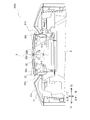
制御部50は、第1垂直フラップ22a及び第2垂直フラップ22bを閉状態から開状態にする時、或いは、開状態から閉状態にする時、第1垂直フラップ22aの回動のタイミングと第2垂直フラップ22bの回動のタイミングとを異ならせる。第1垂直フラップ22aと第2垂直フラップ22bとの間に隙間が殆ど無いため、図6に示すように第1垂直フラップ22aの右端の回動の軌跡T1と第2垂直フラップ22bの左端の回動の軌跡T2とは交差している。そのため、同じタイミングで両垂直フラップ22a,22bを回動させると、第1垂直フラップ22aと第2垂直フラップ22bとが衝突する。しかし、第1垂直フラップ22aの回動のタイミングと第2垂直フラップ22bの回動のタイミングとをずらすことにより、第1垂直フラップ22aと第2垂直フラップ22bとが衝突するのを避ける事が出来る。これにより、閉状態における第1垂直フラップ22aと第2垂直フラップ22bとの間隔をつめる(隙間を小さくする)ことができ、間隔をつめても第1垂直フラップ22aと第2垂直フラップ22bとが互いに干渉せずに回動するようにできる。閉状態における第1垂直フラップ22aと第2垂直フラップ22bとの間隔をつめると、優れた美観を生ずるだけでなく、ゴミ等の異物の吹出口Eへの侵入を抑えることができる。
(2-6)吹出口形成部材
吹出口形成部材40は、樹脂製の部材であり、前述のとおり高さ方向に長い長方形の吹出口Eを形成する。吹出口形成部材40は、吹出口Eの左右の内側壁を形成する左右内側壁部41と、吹出口Eの上下の内側壁を形成する上下内側壁部42とを有する。なお、吹出口形成部材40は、ケーシング部材21とは別の部材となっている。このため、吹出口形成部材40が冷気により冷却されても、その冷温がケーシング部材21に伝わりにくくなっている。
左右内側壁部41の左右それぞれの表面には、正面吹き方向に対する段差が形成されている。具体的には、左右内側壁部41の先端41aは、図6に示すように、近接するケーシング部材21(前面上部パネル21a)の外表面よりも前方に突き出ており、吹出口Eが前方に向かって左右方向に広がるように左右方向斜めに延びる面を有している。つまり、吹出口Eを正面から見ると左右の側壁に吹出口Eが奥に向かって狭くなる段差(傾斜を含む)が設けられている。左右内側壁部41の先端41aの左右方向斜めに延びる面は、後述する最大左右角度θにある状態の垂直フラップ22に平行となるように構成されている。なお、吹出口Eが垂直フラップ22により閉じられた閉状態では、左右内側壁部41の先端41aは、垂直フラップ22の背面側に隠れて外観上視認できない。つまり、垂直フラップ22が閉状態において、左右内側壁部41の先端41aは、第1垂直フラップ22aおよび第2垂直フラップ22bの背後に隠れる。
吹出口形成部材40は、樹脂製の部材であり、前述のとおり高さ方向に長い長方形の吹出口Eを形成する。吹出口形成部材40は、吹出口Eの左右の内側壁を形成する左右内側壁部41と、吹出口Eの上下の内側壁を形成する上下内側壁部42とを有する。なお、吹出口形成部材40は、ケーシング部材21とは別の部材となっている。このため、吹出口形成部材40が冷気により冷却されても、その冷温がケーシング部材21に伝わりにくくなっている。
左右内側壁部41の左右それぞれの表面には、正面吹き方向に対する段差が形成されている。具体的には、左右内側壁部41の先端41aは、図6に示すように、近接するケーシング部材21(前面上部パネル21a)の外表面よりも前方に突き出ており、吹出口Eが前方に向かって左右方向に広がるように左右方向斜めに延びる面を有している。つまり、吹出口Eを正面から見ると左右の側壁に吹出口Eが奥に向かって狭くなる段差(傾斜を含む)が設けられている。左右内側壁部41の先端41aの左右方向斜めに延びる面は、後述する最大左右角度θにある状態の垂直フラップ22に平行となるように構成されている。なお、吹出口Eが垂直フラップ22により閉じられた閉状態では、左右内側壁部41の先端41aは、垂直フラップ22の背面側に隠れて外観上視認できない。つまり、垂直フラップ22が閉状態において、左右内側壁部41の先端41aは、第1垂直フラップ22aおよび第2垂直フラップ22bの背後に隠れる。
(2-7)吹出後冷気進行空間
吹出後冷気進行空間Zは、吹出口Eから吹き出された後の空気(例えば、冷房運転時には、冷気)が進行する空間である。
吹出口形成部材40、ケーシング部材21、及び垂直フラップ22は、吹出後冷気進行空間Zの外にケーシング部材21の外表面が位置するように構成されており、ケーシング部材21の外表面に冷気が接するのを効果的に抑制している。
ケーシング部材21の表面の吹出口形成部材40の左右内側壁部41に近接する領域には、前述の窪み21dが形成されている。このため、図5に示されているように、左右内側壁部41の左右の先端41aは、吹出口Eが近接するケーシング部材21の外表面よりも前に突出したような構造になっている。
吹出後冷気進行空間Zは、吹出口Eから吹き出された後の空気(例えば、冷房運転時には、冷気)が進行する空間である。
吹出口形成部材40、ケーシング部材21、及び垂直フラップ22は、吹出後冷気進行空間Zの外にケーシング部材21の外表面が位置するように構成されており、ケーシング部材21の外表面に冷気が接するのを効果的に抑制している。
ケーシング部材21の表面の吹出口形成部材40の左右内側壁部41に近接する領域には、前述の窪み21dが形成されている。このため、図5に示されているように、左右内側壁部41の左右の先端41aは、吹出口Eが近接するケーシング部材21の外表面よりも前に突出したような構造になっている。
左右内側壁部41の先端41aから窪み21dを形成するケーシング部材21の外表面のうち後方に最も凹んだ部分までの寸法(図5のD1)、即ち窪み21dの深さは、少なくとも10mmとなっている。また、ケーシング部材21の外表面のうち最も前方に位置する部分から仮想面Aまでの距離(図5のD2)は、少なくとも10mmである。即ち、ケーシング部材21は、吹出後冷気進行空間Zから少なくとも10mm離れている。
垂直フラップ22は、その正面吹き方向に対する左右方向への最大の角度である最大左右角度θが、左右内側壁部41の先端41aから最大左右角度θの方向に延びる仮想線を含み且つ鉛直に広がる仮想面Aよりもケーシング部材21が後方に位置するように制御される。吹出口Eから吹出された後の冷気が進行する吹出後冷気進行空間Zは、この仮想面Aから前側に位置する。
垂直フラップ22は、その正面吹き方向に対する左右方向への最大の角度である最大左右角度θが、左右内側壁部41の先端41aから最大左右角度θの方向に延びる仮想線を含み且つ鉛直に広がる仮想面Aよりもケーシング部材21が後方に位置するように制御される。吹出口Eから吹出された後の冷気が進行する吹出後冷気進行空間Zは、この仮想面Aから前側に位置する。
つまり、垂直フラップ22は、その正面吹き方向に対し、左右方向に(第1垂直フラップ22aは左方向に、第2垂直フラップ22bは右方向に)、最大で最大左右角度θだけ傾斜するように制御される。そして、ケーシング部材21は、左右内側壁部41の先端41aから最大左右角度θの方向に延びる仮想線を含んだ鉛直方向に広がる仮想面Aよりも、後方に位置する。つまり、図5のように、ケーシング部材21は、左右内側壁部41の左側の先端41aから正面方向に対して最大左右角度θだけ左側に傾斜する方向に延びる仮想線を含んだ、鉛直方向に広がる仮想面Aよりも後方に位置する。また、図5のように、ケーシング部材21は、左右内側壁部41の右側の先端41aから正面方向に対して最大左右角度θだけ右側に傾斜する方向に延びる仮想線を含んだ、鉛直方向に広がる仮想面Aよりも後方に位置する。吹出後冷気進行空間Zは、これらの仮想面Aより前側に位置する。そのため、ケーシング部材21の外表面は、吹出後冷気進行空間Zの外(吹出後冷気進行空間Zを外れた空間)に位置する。
このように、吹き出された冷気を垂直フラップ22により左右に拡散させてもケーシング部材21の外表面、即ち空調室内機100aの外表面は、吹出後冷気進行空間Zの外に位置する。したがって、当該外表面には、冷房運転時に吹出口Eから吹き出される冷気が触れにくくなっており、結露しにくくなっている。
(3)動作
(3-1)空調機全体の動作
冷房運転時の空調機100の動作について図1を参照しながら説明する。
吸入管10aから圧縮機2に吸い込まれる低圧のガス冷媒は、圧縮されて高温高圧の冷媒となり、吐出管10bへと吐出される。吐出された冷媒は、四路切替弁6を通過し、冷媒配管11aを通り、室外熱交換器3へ流れる。室外熱交換器3へ流れ込んだ冷媒は、空気と熱交換して冷却された後、冷媒配管11bを介して膨張機構4へ到達する。冷媒は、膨張機構4にて減圧・膨張された後、冷媒配管12aを介して室内熱交換器5に流れ込む。冷媒は、室内熱交換器5にて居室R内の空気から熱を奪い、過熱のついた低圧のガス冷媒になる。過熱のついた低圧のガス冷媒になった冷媒は、冷媒配管12bを介して四路切替弁6を通過し、吸入管10aへと流れていく。
(3)動作
(3-1)空調機全体の動作
冷房運転時の空調機100の動作について図1を参照しながら説明する。
吸入管10aから圧縮機2に吸い込まれる低圧のガス冷媒は、圧縮されて高温高圧の冷媒となり、吐出管10bへと吐出される。吐出された冷媒は、四路切替弁6を通過し、冷媒配管11aを通り、室外熱交換器3へ流れる。室外熱交換器3へ流れ込んだ冷媒は、空気と熱交換して冷却された後、冷媒配管11bを介して膨張機構4へ到達する。冷媒は、膨張機構4にて減圧・膨張された後、冷媒配管12aを介して室内熱交換器5に流れ込む。冷媒は、室内熱交換器5にて居室R内の空気から熱を奪い、過熱のついた低圧のガス冷媒になる。過熱のついた低圧のガス冷媒になった冷媒は、冷媒配管12bを介して四路切替弁6を通過し、吸入管10aへと流れていく。
(3-2)空調室内機の動作
空調室内機100aの動作について、図4~図5を参照しながら説明する。
居室R内に設置された空調室内機100aでは、シロッコファン31の回転により居室R内の空気が吸込口Iから空調室内機100a内に吸い込まれる。空調室内機100a内に吸い込まれた空気は、空調室内機100a内を上方に流れ、室内熱交換器5を通過する。室内熱交換器5を通過する際に空気は、熱を奪われ冷気となる。冷気となった調和済の空気は、吹出口Eから居室R内へ吹き出される。吹き出される冷気は、水平フラップ24の上下方向の傾きにより上下方向の風向が調節される。また、吹き出される冷気は、垂直フラップ22の左右方向の傾きにより左右方向の風向が調節される。
(4)空調室内機の特徴
(4-1)
上記実施形態では、空調室内機100aは、床置型であって、吹出口形成部材40と、第1垂直フラップ22aと、第2垂直フラップ22bとを備える。吹出口形成部材40は、調和済空気の吹出口Eを形成する。第1垂直フラップ22aは、その回動軸62が鉛直方向に延び、吹出口Eより吹き出される調和済空気の左右方向の風向を調整する。第1垂直フラップ22aは、閉状態時に吹出口Eの左端近傍部を覆う。第2垂直フラップ22bは、その回動軸62が鉛直方向に延び、吹出口Eより吹き出される調和済空気の左右方向の風向を調整する。第2垂直フラップ22bは、閉状態時に吹出口Eの右端近傍部を覆う。開状態に移行するときに、第1垂直フラップ22aは、その左端が前方に移動し、その右端が後方に移動するように回動する。第2垂直フラップ22bは、その右端が前方に移動し、その左端が後方に移動するように回動する。
空調室内機100aの動作について、図4~図5を参照しながら説明する。
居室R内に設置された空調室内機100aでは、シロッコファン31の回転により居室R内の空気が吸込口Iから空調室内機100a内に吸い込まれる。空調室内機100a内に吸い込まれた空気は、空調室内機100a内を上方に流れ、室内熱交換器5を通過する。室内熱交換器5を通過する際に空気は、熱を奪われ冷気となる。冷気となった調和済の空気は、吹出口Eから居室R内へ吹き出される。吹き出される冷気は、水平フラップ24の上下方向の傾きにより上下方向の風向が調節される。また、吹き出される冷気は、垂直フラップ22の左右方向の傾きにより左右方向の風向が調節される。
(4)空調室内機の特徴
(4-1)
上記実施形態では、空調室内機100aは、床置型であって、吹出口形成部材40と、第1垂直フラップ22aと、第2垂直フラップ22bとを備える。吹出口形成部材40は、調和済空気の吹出口Eを形成する。第1垂直フラップ22aは、その回動軸62が鉛直方向に延び、吹出口Eより吹き出される調和済空気の左右方向の風向を調整する。第1垂直フラップ22aは、閉状態時に吹出口Eの左端近傍部を覆う。第2垂直フラップ22bは、その回動軸62が鉛直方向に延び、吹出口Eより吹き出される調和済空気の左右方向の風向を調整する。第2垂直フラップ22bは、閉状態時に吹出口Eの右端近傍部を覆う。開状態に移行するときに、第1垂直フラップ22aは、その左端が前方に移動し、その右端が後方に移動するように回動する。第2垂直フラップ22bは、その右端が前方に移動し、その左端が後方に移動するように回動する。
両垂直フラップ22は、内向きに引っ込むように回動することにより開く。これにより、吹出口に対して、垂直フラップ22を大きく取れるため、風向調整性能が向上すると共に、停止時に吹出口Eが垂直フラップ22の背面側に隠れる為、外観が美しい。
(4-2)
上記実施形態では、制御部50を更に備える。制御部50は、第1垂直フラップ22aの回動の始動と第2垂直フラップ22bの回動の始動との間に時間差を設けるように制御する。
これにより、両垂直フラップ22の中央部での回転軌跡T1及びT2が交差していても、垂直フラップ22を開く事ができるため、両垂直フラップ22間の隙間をつめる事ができる。その結果、優れた美観を生ずるとともに、停止時に製品内部にゴミが侵入するのを抑えることができる。
(4-2)
上記実施形態では、制御部50を更に備える。制御部50は、第1垂直フラップ22aの回動の始動と第2垂直フラップ22bの回動の始動との間に時間差を設けるように制御する。
これにより、両垂直フラップ22の中央部での回転軌跡T1及びT2が交差していても、垂直フラップ22を開く事ができるため、両垂直フラップ22間の隙間をつめる事ができる。その結果、優れた美観を生ずるとともに、停止時に製品内部にゴミが侵入するのを抑えることができる。
(4-3)
上記実施形態では、本体を形成するケーシング部材21をさらに備える。吹出口形成部材40は、吹出口Eの左右内側壁を形成する左右内側壁部41を有する。ケーシング部材21の外表面は、吹出後冷気進行空間Zの外に位置する。吹出後冷気進行空間Zは、左右内側壁部41の先端41aから垂直フラップ22の正面吹き方向に対する最大左右角度θの方向に延びる仮想面Aから前側の空間である。つまり、吹出後冷気進行空間Zは、左右内側壁部41の左側の先端41aから第1垂直フラップ22aの正面吹き方向に対する最大左右角度θの方向に延びる仮想面と、左右内側壁部41の右側の先端41aから第2垂直フラップ22bの正面吹き方向に対する最大左右角度θの方向に延びる仮想面と、の前側の空間である。
上記実施形態では、本体を形成するケーシング部材21をさらに備える。吹出口形成部材40は、吹出口Eの左右内側壁を形成する左右内側壁部41を有する。ケーシング部材21の外表面は、吹出後冷気進行空間Zの外に位置する。吹出後冷気進行空間Zは、左右内側壁部41の先端41aから垂直フラップ22の正面吹き方向に対する最大左右角度θの方向に延びる仮想面Aから前側の空間である。つまり、吹出後冷気進行空間Zは、左右内側壁部41の左側の先端41aから第1垂直フラップ22aの正面吹き方向に対する最大左右角度θの方向に延びる仮想面と、左右内側壁部41の右側の先端41aから第2垂直フラップ22bの正面吹き方向に対する最大左右角度θの方向に延びる仮想面と、の前側の空間である。
これにより、ケーシング部材21の外表面に冷気が触れるのを抑制し、冷房運転時における結露を抑制する。
(4-4)
上記実施形態では、左右内側壁部41の先端41aは、第1垂直フラップ22aおよび第2垂直フラップ22bが閉状態において、両垂直フラップ22の背後に隠れる。
これにより、優れた美観を生じている。
(5)変形例
上記実施形態では、空調室内機100aは、垂直フラップ22を2つ備えていた。しかし、他の実施形態においては、垂直フラップ22を3つ以上備えていても良い。この場合でも、吹出口Eの両側端に位置する垂直フラップ22、即ち第1垂直フラップ22aおよび第2垂直フラップ22bをそれぞれ上述のとおり内向きに回動させて開状態になるようにすればよい。
(4-4)
上記実施形態では、左右内側壁部41の先端41aは、第1垂直フラップ22aおよび第2垂直フラップ22bが閉状態において、両垂直フラップ22の背後に隠れる。
これにより、優れた美観を生じている。
(5)変形例
上記実施形態では、空調室内機100aは、垂直フラップ22を2つ備えていた。しかし、他の実施形態においては、垂直フラップ22を3つ以上備えていても良い。この場合でも、吹出口Eの両側端に位置する垂直フラップ22、即ち第1垂直フラップ22aおよび第2垂直フラップ22bをそれぞれ上述のとおり内向きに回動させて開状態になるようにすればよい。
本発明は、冷房運転が可能な空調室内機に有用である。
21 ケーシング部材
21d 窪み
22 垂直フラップ(左右風向調整フラップ)
22a 第1垂直フラップ(第1左右風向調整フラップ)
22b 第2垂直フラップ(第2左右風向調整フラップ)
40 吹出口形成部材
41 左右内側壁部
41a 先端
50 制御部
62 回動軸
100a 空調室内機
A 仮想面
E 吹出口
Z 吹出後冷気進行空間
θ 最大左右角度
21d 窪み
22 垂直フラップ(左右風向調整フラップ)
22a 第1垂直フラップ(第1左右風向調整フラップ)
22b 第2垂直フラップ(第2左右風向調整フラップ)
40 吹出口形成部材
41 左右内側壁部
41a 先端
50 制御部
62 回動軸
100a 空調室内機
A 仮想面
E 吹出口
Z 吹出後冷気進行空間
θ 最大左右角度
Claims (4)
- 床置型の空調室内機(100a)であって、
調和済空気の吹出口(E)を形成する吹出口形成部材(40)と、
前記吹出口より吹き出される前記調和済空気の左右方向の風向を調整し、回動軸(62)が鉛直方向に延び、閉状態時に前記吹出口の左端近傍部を覆う第1左右風向調整フラップ(22a)と、
前記吹出口より吹き出される前記調和済空気の左右方向の風向を調整し、回動軸(62)が鉛直方向に延び、閉状態時に前記吹出口の右端近傍部を覆う第2左右風向調整フラップ(22b)と、
を備え、
開状態に移行するときに、前記第1左右風向調整フラップは、その左端が前方に移動し、その右端が後方に移動するように回動し、前記第2左右風向調整フラップは、その右端が前方に移動し、その左端が後方に移動するように回動する、
空調室内機(100a)。 - 前記第1左右風向調整フラップの回動の始動と前記第2左右風向調整フラップの回動の始動との間に時間差を設けるように制御する制御部(50)、
をさらに備えた、
請求項1に記載の空調室内機(100a)。 - 本体を形成するケーシング部材(21)、
をさらに備え、
前記吹出口形成部材は、前記吹出口の左右内側壁を形成する左右内側壁部(41)を有し、
前記ケーシング部材の外表面は、吹出後冷気進行空間(Z)の外に位置し、
前記吹出後冷気進行空間は、前記左右内側壁部の先端(41a)から前記左右風向調整フラップの正面吹き方向に対する最大左右角度(θ)の方向に延びる仮想面(A)から前側の空間である、
請求項2に記載の空調室内機(100a)。 - 前記左右内側壁部の先端は、前記第1左右風向調整フラップおよび前記第2左右風向調整フラップが閉状態において、前記第1左右風向調整フラップおよび前記第2左右風向調整フラップの背後に隠れる、
請求項3に記載の空調室内機(100a)。
Priority Applications (1)
| Application Number | Priority Date | Filing Date | Title |
|---|---|---|---|
| CN201380001661.XA CN103703322B (zh) | 2012-07-26 | 2013-06-10 | 空调室内机 |
Applications Claiming Priority (2)
| Application Number | Priority Date | Filing Date | Title |
|---|---|---|---|
| JP2012165720A JP5382177B1 (ja) | 2012-07-26 | 2012-07-26 | 空調室内機 |
| JP2012-165720 | 2012-07-26 |
Publications (1)
| Publication Number | Publication Date |
|---|---|
| WO2014017190A1 true WO2014017190A1 (ja) | 2014-01-30 |
Family
ID=49997007
Family Applications (1)
| Application Number | Title | Priority Date | Filing Date |
|---|---|---|---|
| PCT/JP2013/065993 Ceased WO2014017190A1 (ja) | 2012-07-26 | 2013-06-10 | 空調室内機 |
Country Status (3)
| Country | Link |
|---|---|
| JP (1) | JP5382177B1 (ja) |
| CN (1) | CN103703322B (ja) |
| WO (1) | WO2014017190A1 (ja) |
Families Citing this family (3)
| Publication number | Priority date | Publication date | Assignee | Title |
|---|---|---|---|---|
| JP6394456B2 (ja) * | 2015-03-25 | 2018-09-26 | 三菱電機株式会社 | 空気清浄機 |
| US10788237B2 (en) * | 2015-03-27 | 2020-09-29 | Goro Sayeki | Wind direction adjusting apparatus of air-conditioning blowout port, and antibacterial member |
| CN113154529A (zh) * | 2021-03-31 | 2021-07-23 | 珠海格力电器股份有限公司 | 室内机、空调器 |
Citations (2)
| Publication number | Priority date | Publication date | Assignee | Title |
|---|---|---|---|---|
| JPH08327132A (ja) * | 1995-05-26 | 1996-12-13 | Kyoritsu Eatetsuku Kk | 風量調整ダンパー |
| JP2003343871A (ja) * | 2002-05-29 | 2003-12-03 | Daikin Ind Ltd | 床置き形空気調和機 |
Family Cites Families (3)
| Publication number | Priority date | Publication date | Assignee | Title |
|---|---|---|---|---|
| JP3812576B2 (ja) * | 2004-08-25 | 2006-08-23 | ダイキン工業株式会社 | 床置き型空気調和機 |
| CN201129804Y (zh) * | 2007-11-16 | 2008-10-08 | 珠海格力电器股份有限公司 | 一种采用新型风道系统的分体落地式空调器 |
| CN202229309U (zh) * | 2011-09-08 | 2012-05-23 | 珠海格力电器股份有限公司 | 空调室内机 |
-
2012
- 2012-07-26 JP JP2012165720A patent/JP5382177B1/ja not_active Expired - Fee Related
-
2013
- 2013-06-10 WO PCT/JP2013/065993 patent/WO2014017190A1/ja not_active Ceased
- 2013-06-10 CN CN201380001661.XA patent/CN103703322B/zh active Active
Patent Citations (2)
| Publication number | Priority date | Publication date | Assignee | Title |
|---|---|---|---|---|
| JPH08327132A (ja) * | 1995-05-26 | 1996-12-13 | Kyoritsu Eatetsuku Kk | 風量調整ダンパー |
| JP2003343871A (ja) * | 2002-05-29 | 2003-12-03 | Daikin Ind Ltd | 床置き形空気調和機 |
Also Published As
| Publication number | Publication date |
|---|---|
| JP5382177B1 (ja) | 2014-01-08 |
| CN103703322B (zh) | 2015-08-05 |
| CN103703322A (zh) | 2014-04-02 |
| JP2014025631A (ja) | 2014-02-06 |
Similar Documents
| Publication | Publication Date | Title |
|---|---|---|
| JP4952775B2 (ja) | 空気調和装置の室内機 | |
| JP6505251B2 (ja) | 空気調和機の室内機 | |
| WO2012046438A1 (ja) | 空気調和機 | |
| JP6639654B2 (ja) | 空気調和機 | |
| JP2013011413A (ja) | 空気調和機 | |
| JP4945678B1 (ja) | 空気調和機 | |
| JP5382177B1 (ja) | 空調室内機 | |
| JP5516666B2 (ja) | 空調室内機 | |
| JP6739619B2 (ja) | 空気調和機の室内機 | |
| WO2019171462A1 (ja) | 室内機および空気調和機 | |
| JP5834208B2 (ja) | 空気調和機 | |
| JP4864159B1 (ja) | 空気調和機 | |
| JP7022739B2 (ja) | 空気調和機 | |
| JP4947224B1 (ja) | 空気調和機 | |
| JP2003343871A (ja) | 床置き形空気調和機 | |
| JP4927212B1 (ja) | 空気調和機 | |
| JP6213853B2 (ja) | 空気調和機 | |
| JP5979454B2 (ja) | 空気調和機 | |
| CN202692266U (zh) | 空调室内机 | |
| JP6956794B2 (ja) | 空気調和機の室内機 | |
| CN202692267U (zh) | 空调室内机 | |
| JP2025138236A (ja) | 空気調和機 | |
| JP2010019490A (ja) | 空気調和装置 | |
| KR20090038183A (ko) | 공기조화기 | |
| JP2015010732A (ja) | 空気調和機 |
Legal Events
| Date | Code | Title | Description |
|---|---|---|---|
| 121 | Ep: the epo has been informed by wipo that ep was designated in this application |
Ref document number: 13822265 Country of ref document: EP Kind code of ref document: A1 |
|
| NENP | Non-entry into the national phase |
Ref country code: DE |
|
| 122 | Ep: pct application non-entry in european phase |
Ref document number: 13822265 Country of ref document: EP Kind code of ref document: A1 |