WO2014017174A1 - カメラおよびその動作制御方法 - Google Patents
カメラおよびその動作制御方法 Download PDFInfo
- Publication number
- WO2014017174A1 WO2014017174A1 PCT/JP2013/065369 JP2013065369W WO2014017174A1 WO 2014017174 A1 WO2014017174 A1 WO 2014017174A1 JP 2013065369 W JP2013065369 W JP 2013065369W WO 2014017174 A1 WO2014017174 A1 WO 2014017174A1
- Authority
- WO
- WIPO (PCT)
- Prior art keywords
- image
- target area
- subject
- focus
- display
- Prior art date
- Legal status (The legal status is an assumption and is not a legal conclusion. Google has not performed a legal analysis and makes no representation as to the accuracy of the status listed.)
- Ceased
Links
Images






Classifications
-
- G—PHYSICS
- G03—PHOTOGRAPHY; CINEMATOGRAPHY; ANALOGOUS TECHNIQUES USING WAVES OTHER THAN OPTICAL WAVES; ELECTROGRAPHY; HOLOGRAPHY
- G03B—APPARATUS OR ARRANGEMENTS FOR TAKING PHOTOGRAPHS OR FOR PROJECTING OR VIEWING THEM; APPARATUS OR ARRANGEMENTS EMPLOYING ANALOGOUS TECHNIQUES USING WAVES OTHER THAN OPTICAL WAVES; ACCESSORIES THEREFOR
- G03B13/00—Viewfinders; Focusing aids for cameras; Means for focusing for cameras; Autofocus systems for cameras
- G03B13/02—Viewfinders
- G03B13/06—Viewfinders with lenses with or without reflectors
-
- H—ELECTRICITY
- H04—ELECTRIC COMMUNICATION TECHNIQUE
- H04N—PICTORIAL COMMUNICATION, e.g. TELEVISION
- H04N23/00—Cameras or camera modules comprising electronic image sensors; Control thereof
- H04N23/60—Control of cameras or camera modules
- H04N23/68—Control of cameras or camera modules for stable pick-up of the scene, e.g. compensating for camera body vibrations
- H04N23/682—Vibration or motion blur correction
-
- G—PHYSICS
- G03—PHOTOGRAPHY; CINEMATOGRAPHY; ANALOGOUS TECHNIQUES USING WAVES OTHER THAN OPTICAL WAVES; ELECTROGRAPHY; HOLOGRAPHY
- G03B—APPARATUS OR ARRANGEMENTS FOR TAKING PHOTOGRAPHS OR FOR PROJECTING OR VIEWING THEM; APPARATUS OR ARRANGEMENTS EMPLOYING ANALOGOUS TECHNIQUES USING WAVES OTHER THAN OPTICAL WAVES; ACCESSORIES THEREFOR
- G03B13/00—Viewfinders; Focusing aids for cameras; Means for focusing for cameras; Autofocus systems for cameras
- G03B13/18—Focusing aids
- G03B13/20—Rangefinders coupled with focusing arrangements, e.g. adjustment of rangefinder automatically focusing camera
-
- G—PHYSICS
- G02—OPTICS
- G02B—OPTICAL ELEMENTS, SYSTEMS OR APPARATUS
- G02B7/00—Mountings, adjusting means, or light-tight connections, for optical elements
- G02B7/02—Mountings, adjusting means, or light-tight connections, for optical elements for lenses
- G02B7/04—Mountings, adjusting means, or light-tight connections, for optical elements for lenses with mechanism for focusing or varying magnification
- G02B7/09—Mountings, adjusting means, or light-tight connections, for optical elements for lenses with mechanism for focusing or varying magnification adapted for automatic focusing or varying magnification
-
- G—PHYSICS
- G03—PHOTOGRAPHY; CINEMATOGRAPHY; ANALOGOUS TECHNIQUES USING WAVES OTHER THAN OPTICAL WAVES; ELECTROGRAPHY; HOLOGRAPHY
- G03B—APPARATUS OR ARRANGEMENTS FOR TAKING PHOTOGRAPHS OR FOR PROJECTING OR VIEWING THEM; APPARATUS OR ARRANGEMENTS EMPLOYING ANALOGOUS TECHNIQUES USING WAVES OTHER THAN OPTICAL WAVES; ACCESSORIES THEREFOR
- G03B13/00—Viewfinders; Focusing aids for cameras; Means for focusing for cameras; Autofocus systems for cameras
- G03B13/02—Viewfinders
- G03B13/06—Viewfinders with lenses with or without reflectors
- G03B13/08—Viewfinders with lenses with or without reflectors with reflected image of frame
-
- G—PHYSICS
- G03—PHOTOGRAPHY; CINEMATOGRAPHY; ANALOGOUS TECHNIQUES USING WAVES OTHER THAN OPTICAL WAVES; ELECTROGRAPHY; HOLOGRAPHY
- G03B—APPARATUS OR ARRANGEMENTS FOR TAKING PHOTOGRAPHS OR FOR PROJECTING OR VIEWING THEM; APPARATUS OR ARRANGEMENTS EMPLOYING ANALOGOUS TECHNIQUES USING WAVES OTHER THAN OPTICAL WAVES; ACCESSORIES THEREFOR
- G03B13/00—Viewfinders; Focusing aids for cameras; Means for focusing for cameras; Autofocus systems for cameras
- G03B13/18—Focusing aids
-
- G—PHYSICS
- G03—PHOTOGRAPHY; CINEMATOGRAPHY; ANALOGOUS TECHNIQUES USING WAVES OTHER THAN OPTICAL WAVES; ELECTROGRAPHY; HOLOGRAPHY
- G03B—APPARATUS OR ARRANGEMENTS FOR TAKING PHOTOGRAPHS OR FOR PROJECTING OR VIEWING THEM; APPARATUS OR ARRANGEMENTS EMPLOYING ANALOGOUS TECHNIQUES USING WAVES OTHER THAN OPTICAL WAVES; ACCESSORIES THEREFOR
- G03B13/00—Viewfinders; Focusing aids for cameras; Means for focusing for cameras; Autofocus systems for cameras
- G03B13/32—Means for focusing
- G03B13/34—Power focusing
-
- G—PHYSICS
- G03—PHOTOGRAPHY; CINEMATOGRAPHY; ANALOGOUS TECHNIQUES USING WAVES OTHER THAN OPTICAL WAVES; ELECTROGRAPHY; HOLOGRAPHY
- G03B—APPARATUS OR ARRANGEMENTS FOR TAKING PHOTOGRAPHS OR FOR PROJECTING OR VIEWING THEM; APPARATUS OR ARRANGEMENTS EMPLOYING ANALOGOUS TECHNIQUES USING WAVES OTHER THAN OPTICAL WAVES; ACCESSORIES THEREFOR
- G03B17/00—Details of cameras or camera bodies; Accessories therefor
- G03B17/18—Signals indicating condition of a camera member or suitability of light
-
- G—PHYSICS
- G03—PHOTOGRAPHY; CINEMATOGRAPHY; ANALOGOUS TECHNIQUES USING WAVES OTHER THAN OPTICAL WAVES; ELECTROGRAPHY; HOLOGRAPHY
- G03B—APPARATUS OR ARRANGEMENTS FOR TAKING PHOTOGRAPHS OR FOR PROJECTING OR VIEWING THEM; APPARATUS OR ARRANGEMENTS EMPLOYING ANALOGOUS TECHNIQUES USING WAVES OTHER THAN OPTICAL WAVES; ACCESSORIES THEREFOR
- G03B17/00—Details of cameras or camera bodies; Accessories therefor
- G03B17/18—Signals indicating condition of a camera member or suitability of light
- G03B17/20—Signals indicating condition of a camera member or suitability of light visible in viewfinder
-
- H—ELECTRICITY
- H04—ELECTRIC COMMUNICATION TECHNIQUE
- H04N—PICTORIAL COMMUNICATION, e.g. TELEVISION
- H04N23/00—Cameras or camera modules comprising electronic image sensors; Control thereof
- H04N23/60—Control of cameras or camera modules
- H04N23/63—Control of cameras or camera modules by using electronic viewfinders
- H04N23/633—Control of cameras or camera modules by using electronic viewfinders for displaying additional information relating to control or operation of the camera
- H04N23/635—Region indicators; Field of view indicators
-
- H—ELECTRICITY
- H04—ELECTRIC COMMUNICATION TECHNIQUE
- H04N—PICTORIAL COMMUNICATION, e.g. TELEVISION
- H04N23/00—Cameras or camera modules comprising electronic image sensors; Control thereof
- H04N23/60—Control of cameras or camera modules
- H04N23/64—Computer-aided capture of images, e.g. transfer from script file into camera, check of taken image quality, advice or proposal for image composition or decision on when to take image
-
- H—ELECTRICITY
- H04—ELECTRIC COMMUNICATION TECHNIQUE
- H04N—PICTORIAL COMMUNICATION, e.g. TELEVISION
- H04N23/00—Cameras or camera modules comprising electronic image sensors; Control thereof
- H04N23/60—Control of cameras or camera modules
- H04N23/67—Focus control based on electronic image sensor signals
- H04N23/675—Focus control based on electronic image sensor signals comprising setting of focusing regions
-
- H—ELECTRICITY
- H04—ELECTRIC COMMUNICATION TECHNIQUE
- H04N—PICTORIAL COMMUNICATION, e.g. TELEVISION
- H04N23/00—Cameras or camera modules comprising electronic image sensors; Control thereof
- H04N23/60—Control of cameras or camera modules
- H04N23/68—Control of cameras or camera modules for stable pick-up of the scene, e.g. compensating for camera body vibrations
- H04N23/681—Motion detection
- H04N23/6811—Motion detection based on the image signal
-
- G—PHYSICS
- G03—PHOTOGRAPHY; CINEMATOGRAPHY; ANALOGOUS TECHNIQUES USING WAVES OTHER THAN OPTICAL WAVES; ELECTROGRAPHY; HOLOGRAPHY
- G03B—APPARATUS OR ARRANGEMENTS FOR TAKING PHOTOGRAPHS OR FOR PROJECTING OR VIEWING THEM; APPARATUS OR ARRANGEMENTS EMPLOYING ANALOGOUS TECHNIQUES USING WAVES OTHER THAN OPTICAL WAVES; ACCESSORIES THEREFOR
- G03B2217/00—Details of cameras or camera bodies; Accessories therefor
- G03B2217/18—Signals indicating condition of a camera member or suitability of light
- G03B2217/185—Signals indicating condition of a camera member or suitability of light providing indication that the picture may be blurred
-
- H—ELECTRICITY
- H04—ELECTRIC COMMUNICATION TECHNIQUE
- H04N—PICTORIAL COMMUNICATION, e.g. TELEVISION
- H04N2101/00—Still video cameras
Definitions
- This invention relates to a camera and its operation control method.
- Patent Document 1 Some digital cameras are equipped with a device having both optical and electronic viewfinders (Patent Document 1). A fine optical subject image can be seen with the optical viewfinder, and the same subject image as the subject image taken with the electronic viewfinder can be seen.
- a main image of the image sensor of the main imaging unit is overlaid with a partial image cut out from the sub-image of the image sensor of the sub-imaging unit (Patent Document 2), a conventional image-matching optical range
- Patent Document 3 a conventional image-matching optical range
- camera shake when the camera shake amount is large, the face area is not enlarged, and when the camera shake amount is small, an image in which the face area is enlarged is superimposed on the entire image (patent) Document 4), there is also a technique that darkens the subject image by using a deflection filter or the like so that the shake is not recognized (Patent Document 5).
- An object of the present invention is to eliminate a sense of incongruity that occurs when a subject or a camera moves when a double image coincidence method is applied to a finder having both optical and electronic functions.
- the camera according to the present invention has a focus lens built therein and a rotatable focus ring provided around the lens.
- a lens barrel that adjusts the position of the focus lens according to the rotation of the focus ring,
- a solid-state electronic imaging device that captures an image of a subject formed by a lens and outputs image data representing the subject image, and an image within a desired AF target region among subject images represented by image data output from the solid-state electronic imaging device
- a display device that displays the image on the display screen, a finder device that is formed on the front of the camera and has an objective window that faces the subject and an eyepiece window that looks into the optical subject image through the objective window, and between the objective window and the eyepiece window
- a deflecting device that is provided and guides an image in the AF target area displayed on the display screen of the display device to the eyepiece window; If the image in the F target area is out of focus, the image in the AF target area is displayed on the display screen so that the optical subject image seen through the objective window and the image
- the second display control for controlling the display device so as to erase the image displayed on the display screen of the display device under the control of the first sign control means Characterized in that it comprises a stage.
- This invention also provides an operation control method suitable for a camera.
- this method has a built-in focus lens and a rotatable focus ring provided around it, and the lens barrel and camera that adjust the position of the focus lens according to the rotation of the focus ring.
- the solid-state electronic imaging device is connected by a focus lens.
- the subject to be imaged is imaged, image data representing the subject image is output, and the display device displays the image within the desired AF target area among the subject images represented by the image data output from the solid-state electronic imaging device.
- the deflection device is provided between the objective window and the eyepiece window and is displayed on the display screen of the display device.
- the image in the AF target area is guided to the eyepiece window, and the first display control means, when the image in the AF target area is out of focus, the optical subject image that can be seen through the objective window, the image in the AF target area, If the image in the AF target area is displayed on the display screen so that the image is out of focus, and the image in the AF target area is in focus, the optical subject image that can be seen through the objective window matches the image in the AF target area.
- the display device is controlled to display an image in the AF target area on the display screen, and the motion determination means determines whether the camera or the subject is moving above the threshold value, and the second display control means
- the display screen of the display device is controlled by the first display control means in response to the movement determination means determining that the camera or subject is moving above the threshold value. And it controls the display device so as to erase the image displayed on.
- the finder device when viewed through the eyepiece window of the finder device, an optical subject image formed through the objective window of the finder device can be seen.
- the subject is imaged by the solid-state electronic imaging device, and the image in the AF target area among the subject images obtained by the imaging is displayed on the display screen of the display device.
- the image in the AF target area displayed on the display screen is guided to the eyepiece window of the finder device by the deflecting device and superimposed on the optical subject image. If the image in the AF target area is not in focus, the optical subject image and the image in the AF target area are misaligned.
- the optical subject image and the AF target area is displayed on the display screen of the display device so that the images match with each other without deviation.
- a so-called double image matching type finder apparatus can be realized.
- the image when the camera or the subject moves above the threshold value, the image is erased without being displayed on the display screen.
- the camera or the subject when the camera or the subject is moving, not only does it feel uncomfortable as described above, but it is difficult to focus, so focusing using the so-called image double matching method is stopped.
- the first display control means may include rotation amount detection means for detecting the rotation amount of the focus ring. In this case, based on the rotation amount detected by the rotation amount detection means, if the image in the AF target area is out of focus, the optical subject image seen through the objective window and the image in the AF target area are at least horizontally. The image in the AF target area is displayed on the display screen so as to deviate in the direction. If the image in the AF target area is in focus, the optical subject image seen through the objective window matches the image in the AF target area. Thus, the display device will be controlled to display the image in the AF target area on the display screen.
- the first display control means based on the rotation amount detected by the rotation amount detection means, if the image in the AF target area is out of focus, the optical object image visible through the objective window and the AF target area
- the image in the AF target area is displayed on the display screen so that the image is shifted on the axis connecting the optical axis of the lens barrel and the optical axis of the viewfinder device.
- the objective is The display device may be controlled so that the image in the AF target area is displayed on the display screen so that the optical subject image seen through the window matches the image in the AF target area.
- the first display control means moves the image in the AF target area at least in the horizontal direction according to the rotation of the focus ring, and when the focus lens focus position matches the distance to the subject,
- the display device may be controlled so that the image in the AF target area is displayed on the display screen so that the optical subject image seen through the window matches the image in the AF target area.
- the first display control means includes a rotation amount detection means for detecting the rotation amount of the focus ring, and a subject at a distance in front of the camera based on the rotation amount detected by the rotation amount detection means.
- the image of the AF target area displayed on the display screen of the display device may be matched.
- the first display control unit corrects, for example, a deviation between the optical object image seen through the objective window and the image in the AF target area due to a deviation between the optical axis of the solid-state electronic imaging device and the optical axis of the finder device.
- the image within the AF target area is displayed on the display screen.
- the first display control means detects the shift between the optical object image seen through the objective window and the image in the AF target area due to the shift between the optical axis of the solid-state electronic imaging device and the optical axis of the viewfinder device.
- the correction amount corresponding to the distance calculated by the calculation means may be corrected, and the image in the AF target area may be displayed on the display screen.
- a first AF target area setting means for setting at least one of the position, size and number of AF target areas may be further provided.
- a second AF target area setting unit that sets at least one of brightness and density of an image in the AF target area may be further provided.
- Face detection means for detecting a face area included in a subject image picked up by a solid-state electronic imaging device, and third AF target area setting means for setting the face area detected by the face detection means as an AF target area May be further provided.
- FIG. 1 to FIG. 3 show an embodiment of the present invention and show the appearance of the digital camera 1.
- 1 is a front view
- FIG. 2 is a rear view
- FIG. 3 is a perspective view seen from the back.
- a lens barrel 2 protruding forward is provided at substantially the center of the front of the digital camera 1.
- an optical view finder is formed, and an objective window 3 facing the subject is formed.
- a strobe light emitting device 4 is provided on the left side of the objective window 3.
- a shutter speed dial 6, a power lever 7, a shutter release button 8 and an exposure dial 9 are provided on the left side of the top surface of the digital camera 1 when viewed from the front.
- the shutter speed dial 6 is a rotatable circular knob.
- the user can set a desired shutter speed by rotating the shutter speed dial 6.
- the power lever 7 can be moved a predetermined angle to the right and left as viewed from the front.
- the user can turn on / off the power of the digital camera 1 by moving the power lever 7 by a predetermined angle.
- the power lever 7 has an annular space inside, and a shutter release button 8 is provided in the space.
- the exposure dial 9 is also a rotatable circular knob. The user can correct the exposure by rotating the exposure dial 9.
- a focus setting lever 20 is formed at the right end when viewed from the front of the digital camera 1. This focus setting lever 20 is slidable up and down, and can set a double image coincidence type manual focus (details will be described later) or an auto focus.
- a display screen 12 of the liquid crystal display device is formed over almost the entire back surface of the digital camera 1.
- An eyepiece window 11 constituting a finder device is formed on the upper left of the back of the digital camera 1.
- a command lever 10 that can be moved left and right is provided at the upper right of the back of the digital camera 1. The user can give a command to the digital camera 1 such as aperture adjustment at 1/3 EV step during manual exposure by operating the command lever.
- an AF (automatic focus adjustment) / AE (automatic exposure) lock button 13 Under the command lever 10, an AF (automatic focus adjustment) / AE (automatic exposure) lock button 13, a command dial 14, a menu / OK button 15, a back button 16, a RAW button 17, etc. are provided. Yes.
- the shutter speed dial 6, the power lever 7, the shutter release button 8, and the exposure are provided on the right side (right side as viewed from the back) of the top surface of the digital camera 1.
- a dial 9 is provided.
- the power lever 7 is formed with the protrusion 7A protruding in the front direction. When the projection 7A is pinched and moved left and right, the power of the digital camera 1 can be turned on and off.
- the subject By approaching the eyepiece window 11 of the finder device and looking through the eyepiece window 11, the subject can be seen through the objective window 3 and the eyepiece window 11, and the camera angle can be determined.
- FIG. 4 is a block diagram showing the electrical configuration of the digital camera 1.
- the overall operation of the digital camera 1 is controlled by the CPU 47.
- the digital camera 1 includes a solid-state electronic image sensor 41.
- a focus lens group 31 built in the lens barrel 2 is positioned in front of the solid-state electronic image sensor 34.
- a rotatable focus ring 32 is provided around the lens barrel 2.
- the focus ring group 31 is positioned according to the operation of the focus ring 32 by the user.
- a video signal representing the subject image is output from the solid-state electronic image pickup device 41.
- the video signal is input to the analog / digital conversion circuit 43 via the sample / hold circuit 42.
- the analog / digital conversion circuit 43 converts the video signal into digital image data.
- the converted digital image data is subjected to predetermined signal processing such as white balance adjustment and gamma correction in the signal processing circuit 44.
- the digital image data output from the signal processing circuit 44 is given to an LCD (Liquid Crystal Display) driver 48 via a memory 46.
- the LCD driver 48 controls the liquid crystal display device 12 (using the same reference numerals as the display screen), and the subject image captured by the solid-state electronic image sensor 41 is displayed on the display screen of the liquid crystal display device 12.
- the image data input to the memory 46 is recorded on the memory card 50 under the control of the memory card controller 49 as described above.
- the digital camera 1 is also provided with a camera shake sensor 51.
- the camera shake sensor 51 detects an angular velocity due to camera shake of the digital camera 1.
- the digital camera 1 is also provided with a movement amount calculation circuit 52 for calculating the movement amount of the subject.
- the movement amount calculation circuit 52 detects the same image portion from two consecutive frames (not necessarily continuous) of subject images by image recognition processing or the like, and calculates the movement amount of the image portion. The moving speed of the moving subject can be determined from the calculated moving amount of the subject.
- the image data output from the signal processing circuit 44 is input to the digital / analog conversion circuit 45.
- the image data is converted back to an analog video signal in the digital / analog conversion circuit 45 and applied to the image shift circuit 35.
- the rotation amount of the focus ring 32 is detected by the encoder 33.
- a signal indicating the detected rotation amount is input to the distance calculation circuit 34.
- the image shift circuit 35 also receives a video signal representing a subject image. As will be described in detail later, processing for shifting the subject image is performed in the image shift circuit 35 in accordance with the calculated distance.
- the video signal output from the image shift circuit 35 is given to the electronic view finder 65 of the finder device 60 by the LCD driver 36.
- the electronic view finder 65 is a liquid crystal display device. The subject image obtained by imaging can be displayed on the display screen of the electronic viewfinder 65.
- an eyepiece lens 66 is provided in front of the eyepiece window 11, and a prism 63 in which a half mirror 64 is formed is provided in front of the eyepiece lens 66.
- the half mirror 64 is formed to have an incident angle of 45 degrees with respect to the optical axis C3 of the optical viewfinder 60.
- An OVF (optical viewfinder) shutter (which may be a mechanical shutter or a liquid crystal shutter) 62 and an objective lens 61 are provided in front of the prism 63.
- the subject image of the subject OB formed by the objective lens 61 and the eyepiece 66 can be viewed from the eyepiece window 11. Further, when a subject image obtained by imaging is displayed on the display screen of the electronic view finder 65 while the OVF shutter 62 is open, the light beam representing the subject image is reflected by the half mirror 64, and the electronic view is displayed. The user can see the subject image displayed on the display screen of the finder 65. The subject image displayed on the display screen of the electronic view finder 65 can be overlaid on the optical subject image formed by the objective lens 61 or the like.
- the optical axis of the lens barrel 2 (the optical axis of the lens barrel 2 is the same as the optical axis of the solid-state electronic image pickup device 41) is C2
- the optical axis of the finder device 60 is C3
- the optical axis C2 and the optical axis Does not match C3. For this reason, a parallax with a parallax angle ⁇ is generated between the subject OB viewed from the viewfinder device 60 and the subject OB imaged using the lens barrel 2.
- the subject image displayed on the display screen of the electronic viewfinder 65 is superimposed on the optical subject image seen from the viewfinder device 60, the same subject OB is seen,
- the optical subject image seen from the viewfinder device 60 and the subject image displayed on the electronic viewfinder 65 are shifted due to parallax.
- the subject image is shifted in the image shift circuit 35 so that the parallax is corrected in the image shift circuit 35 described above.
- the focus lens group 31 is positioned by the focus ring 32 so as to focus on the subject OB, an optical subject image that can be seen from the eyepiece window 11 of the viewfinder device 60 is displayed on the electronic viewfinder 65.
- the optical subject image seen from the eyepiece window 11 of the viewfinder device 60 does not match the subject image displayed on the electronic viewfinder 65.
- a so-called image matching type finder device can be realized.
- FIG. 5 shows the relationship between the lens barrel 2 and the objective window 3 when the digital camera 1 is viewed from the front.
- the optical axis C2 of the lens barrel 2 and the optical axis C3 of the optical viewfinder 60 are separated by a distance d and have parallax. For this reason, when the subject does not exist at a position that can be regarded as infinity, a deviation occurs between the subject image viewed through the eyepiece window 3 and the subject image captured by the lens barrel 2. As described above, when the subject image picked up by the solid-state electronic image pickup device 34 is displayed on the electronic view finder 65 and superimposed on the optical subject image formed through the objective window 3, the subject is taken into account due to this parallax. Even if the focus / lens group 31 is positioned so that the subject is in focus, a part of the subject image displayed on the electronic viewfinder 65 may not match the optical subject image.
- FIG. 6 shows a state in which the subject OB is viewed through the lens barrel 2 (imaging) and a state in which the subject OB is viewed from the eyepiece window 3 of the finder device 60.
- the distance between the optical axis C2 of the lens barrel 2 and the optical axis C3 of the eyepiece window 3 is d.
- D the distance from the lens barrel 2 to the subject OB.
- the lens barrel 2 solid-state electronic image pickup device 41
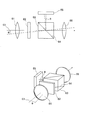
- FIG. 7 shows the structure of the finder device 60.
- the upper diagram in FIG. 7 shows the viewfinder device 60 in a plan view as in FIG. 4, and the lower diagram in FIG. 7 shows the viewfinder device 60 in three dimensions.
- the same reference numerals are given to the same components as those shown in FIG.
- FIG. 8 is a plan view of the positional relationship between the digital camera 1 and the main subjects OB1, OB2, and OB3.
- the parallax angle formed from the optical axis of the eyepiece window 3 is ⁇ 1.
- the main subject OB2 is at a middle distance D2 that is neither far nor near from the digital camera 1
- the parallax formed from the optical axis of the eyepiece window 3 The angle is ⁇ 2.
- the parallax angle formed from the optical axis of the eyepiece window 3 is ⁇ 3.
- parallax angles ⁇ 1, ⁇ 2, and ⁇ 3 are ⁇ 1 ⁇ 2 ⁇ 3.
- the parallax angle is almost negligible when the subject is at a position far enough to be considered as infinity. In that case, there is almost no deviation between the optical subject image seen through the eyepiece window 3 and the subject image displayed on the electronic viewfinder 65. Therefore, the above-described parallax correction is not necessarily required when viewing a subject that is far from the digital camera 1.
- FIG. 9 is an example of an optical subject image 70 that can be seen through the objective window 3 of the finder device 60.
- the main subject image 72 which is an object to be focused on, is positioned approximately at the center of the subject image 70.
- FIG. 10 is an example of an electronic view finder image 80 displayed on the display screen of the electronic view finder 65.
- one AF target area 81 is formed substantially at the center.
- a subject image 82 picked up by the solid-state electronic image pickup device 41 is displayed in the AF target area 81 (shown by a chain line in FIG. 10 so that it can be seen that the image is obtained by image pickup).
- a region around the AF target region 82 is a mask region 85.
- the mask area 85 is for masking an image that is not displayed in the AF target area 82 among the subject images picked up by the solid-state electronic image pickup device 41.
- visual field frames 83 indicating the imaging range are displayed at the four corners of the electronic view finder image 80.
- Data indicating the mask area 85 and the field frame 83 is stored in the memory 46, and these data are read from the memory 46 by the CPU 47 and given to the LCD driver 36, whereby the mask area 85 and the field frame 83 are displayed. Is done.
- FIG. 11 is an example of a viewfinder image that can be seen from the eyepiece window 11.
- the subject image 82 displayed on the electronic viewfinder 65 is subjected to parallax correction.
- the display position of the electronic view finder 65 is shifted by the image shift circuit 35. For this reason, if the subject image 82 in the AF target area 81 is in focus, the subject image 82 superimposed on the optical subject image 72 matches, and the subject image 82 in the AF target area 81 is in focus. If they do not match, a deviation from the subject image 82 superimposed on the optical subject image 72 occurs.
- Manual focus can be achieved by operating the focus ring 32 in accordance with the deviation between the optical subject image 72 and the captured subject image 82.
- FIG. 12 is a flowchart showing the focusing processing procedure.
- the display of the electronic view finder 65 is turned off (step 103 in FIG. 12). Since the electronic viewfinder 65 is turned off, the user will shoot while viewing the subject image displayed on the liquid crystal display screen 12 formed on the back of the digital camera 1.
- the OVF shutter 62 may be closed to display the subject image on the electronic viewfinder 65. The subject image displayed on the electronic viewfinder 65 can be taken while looking through the eyepiece window 11.
- the OVF shutter 62 is opened. An optical subject image can be viewed from the viewfinder device 60.
- the user looks through the eyepiece window 11 of the finder device 60 and operates the focus ring 32 while viewing the optical subject image (step 91 in FIG. 12).
- the amount of rotation of the focus ring 32 is detected by the encoder 33 (step 92 in FIG. 12), and the distance from the digital camera 1 at which the focus lens group 31 is focused to the subject is calculated (step 93 in FIG. 12).
- the relationship between the rotation amount of the focus ring 32 and the distance from the digital camera 1 to which the focus lens group 31 is focused to the subject is detected in advance in the manufacturing process of the digital camera 1 and shows the relationship between them.
- the data is stored in a memory (not shown) in the distance detection circuit 34.
- the distance from the digital camera 1 at which the focus lens group 31 is focused to the subject is calculated from the rotation amount of the focus lens group 31 using the data indicating the relationship.
- the image shift amount for parallax correction is calculated according to the calculated distance (step 94 in FIG. 12). It goes without saying that the relationship between the distance from the digital camera 1 to which the focus lens group 31 is focused and the subject and the shift amount is also calculated and stored in advance in the manufacturing process of the digital camera.
- the subject image picked up by the solid-state electronic image pickup device 41 is shifted by the image shift amount calculated according to the rotation amount of the focus ring 31 and displayed on the display screen of the electronic view finder 65 (FIG. 12). Step 95).
- the subject image 82 in the AF target area 81 deviates from the optical subject image 72 if it is not in focus, and matches the optical subject image 72 if it is in focus.
- the viewfinder device 60 is a so-called double image conforming type. For example, referring to FIG. 8, the focus ring 32 is focused so as to focus on the subject OB1 or the subject OB3 at the distance D1 or D3 even though the subject is the subject OB2 at the distance D2. It is assumed that it has been operated.
- a user looking through the finder device 60 sees a subject image that is doubly shifted.
- the focus ring 32 is operated so as to focus on the subject OB2 at the distance D2 by operating the focus ring 32, a subject image without image shift is visible to the user looking through the viewfinder device 60.
- the digital camera 1 has camera shake, and the camera shake sensor 51 detects the angular velocity of the digital camera 1. If the detected angular velocity is greater than or equal to the first threshold value (YES in step 96 in FIG. 12), the captured subject image will be blurred, so that AF displayed on the electronic viewfinder 65 is in focus. The subject image 82 in the target area 81 and the optical subject image 72 do not match. For this reason, the display on the display screen of the electronic view finder 65 is turned off (step 97 in FIG. 12). When the angular velocity is equal to or lower than the first threshold value (YES in step 98 in FIG.
- step 91 the processing from step 91 is repeated again, and the image 82 in the AF target area 81 is displayed on the display screen of the electronic viewfinder 65.
- the threshold value YES in step 96 in FIG. 12
- the display screen of the electronic viewfinder 65 is turned off, the subject image displayed on the liquid crystal display screen 12 is viewed. Since manual focus is often performed, even when the angular velocity is equal to or higher than the threshold value (YES in step 96 in FIG. 12), the OVF shutter 62 is turned off and the eyepiece window 11 moves to the electronic view finder 65. It is preferable that the displayed subject image can be seen.
- the electronic viewfinder 65 will display not only the image in the AF target area 81 but also the entire captured subject image as shown in FIG. Even when there is a camera shake, manual focusing can be continued while looking at the object image displayed on the display screen of the electronic viewfinder 65 while looking through the eyepiece window 11.
- the movement amount calculation circuit 52 calculates the movement amount of the subject. When there are a plurality of moving subjects in the captured subject image, the movement amount may be calculated for the subject with the largest movement, or the movement amount for the subject existing in the AF target area 81. May be calculated. If the calculated amount of movement of the subject is less than the second threshold value, there is little camera shake and there is no fast-moving subject, so the above-mentioned double image coincidence type manual focus is used for focusing. .
- the subject movement amount is equal to or greater than the second threshold value (YES in step 99 in FIG. 13)
- the subject movement speed is high, so it is not suitable for manual focus by the double image coincidence type. For this reason, the display on the display screen of the electronic view finder 65 is turned off. The user will perform manual focus processing while viewing the subject image displayed on the display screen 12 of the liquid crystal display device.
- the OVF shutter 62 may be turned off and the entire captured subject image may be displayed on the display screen of the electronic viewfinder 65. Manual focus can be realized while looking through the eyepiece window 11 through the entire subject image displayed on the display screen of the electronic viewfinder 65. If the subject movement amount is less than the second threshold value, the processes of steps 96 and 98 are repeated, but the process of step 91 may be repeated.
- step 101 in FIG. 13 If the imaging mode is not turned off (NO in step 101 in FIG. 13), if the subject movement amount is equal to or less than the threshold (YES in step 102 in FIG. 13), the processing from step 91 in FIG. 12 is repeated again.
- the display on the display screen of the electronic viewfinder 65 is turned off even if the double image coincidence type manual focus mode is set.
- the OVF shutter 62 is closed and the entire subject image captured by the electronic viewfinder 65 is displayed.
- the manual focus setting itself itself may be canceled to enable auto focus.
- the OVF shutter 62 may be opened to turn off the display screen of the electronic viewfinder 65, and the camera angle may be determined while looking at the optical subject image from the eyepiece window 11.
- the OVF shutter 62 may be closed to display the captured subject image on the electronic viewfinder 65, and the camera angle may be determined while viewing the subject image displayed on the electronic viewfinder 65 from the eyepiece window 11.
- the camera angle may be determined while looking at the subject image displayed on the display screen of the liquid crystal display device 12 without looking through the eyepiece window 11.
- image data representing the captured subject image is recorded in the memory card 50.
- FIG. 14 shows a modification and is an example of an AF target frame size setting image.
- the AF target frame size setting menu can be selected.
- an AF target frame size setting image shown in FIG. 14 is displayed on the liquid crystal display screen 12.
- a size setting bar 106 extending in the horizontal direction is formed at the bottom of the AF target frame size setting image.
- a slider 101 that freely moves in the horizontal direction on the size setting bar 101 is also formed.
- the AF target frame size setting menu is set, by operating a predetermined button among the buttons included in the digital camera 1, the slider 105 moves left and right on the size setting bar 106.
- the size of the AF target region 81 decreases, and as the slider 105 moves to the right side, the size of the AF target region 81 increases as indicated by a chain line. In this way, the size of the AF target area 81 can be set to a desired size.
- FIG. 15 shows another modified example, which is an AF target density setting image.
- the menu display screen is selected using the menu / OK button 15 among the buttons included in the digital camera 1, the AF target density setting menu is selected. Is possible.
- the AF target density setting menu is selected, a setting image shown in FIG. 15 is displayed on the liquid crystal display screen 12.
- a density setting bar 108 extending in the horizontal direction is also formed at the bottom of the AF target density setting image.
- a slider 107 that freely moves in the horizontal direction on the density setting bar 108 is also formed.
- the slider 107 moves left and right on the density setting bar 108 by operating a predetermined button among the buttons included in the digital camera 1.
- the subject image 82 displayed in the AF target area 81 becomes thinner, and as the slider 102 moves to the right, the subject image 82 displayed in the AF target area 81 becomes darker. In this way, the density of the subject image displayed in the AF target area 81 can be set.
- FIG. 16 shows another modification, and is an example of an electronic view / finder image 80A displayed on the display screen of the electronic view / finder 65.
- FIG. This corresponds to the electronic view finder image 80 shown in FIG.
- one AF target area 81 is set at almost the center.
- the AF target area 81 in addition to the AF target area 81 being set at almost the center, the AF target area 81 is set.
- Four AF target areas 111 to 114 are set around 81.
- the menu display screen is set and the AF target area setting menu is selected in the same manner as described above. Then, the number of AF targets to be set can be input, and the position for setting the AF target area can be input.
- a touch panel or the like may be provided on the display screen 12, and the position of the AF target area may be defined on the touch panel. However, as shown in FIG. 15, it is defined in advance so that any one of the five AF target areas 81, 111 to 114 and one AF target area 81 can be set as shown in FIG. You may make it select. Needless to say, a corresponding image portion of the subject image captured by the solid-state electronic image sensor 41 is displayed in the plurality of AF target areas 81 and 111 to 114.
- FIG. 17 shows still another modification, which is an example of a captured subject image.
- the face image 121 is detected by imaging the subject.
- the area of the detected face image 121 is set as the AF target area 81.
- the face detection may be executed by the CPU 47. Focus on the face.
Landscapes
- Physics & Mathematics (AREA)
- General Physics & Mathematics (AREA)
- Engineering & Computer Science (AREA)
- Multimedia (AREA)
- Signal Processing (AREA)
- Optics & Photonics (AREA)
- Studio Devices (AREA)
- Viewfinders (AREA)
- Indication In Cameras, And Counting Of Exposures (AREA)
Description
この発明は,カメラおよびその動作制御方法に関する。
ディジタル・カメラには光学式と電子式の両方のファインダを持つ装置が搭載されているものがある(特許文献1)。光学式のファインダにより精細である光学的な被写体像を見ることができ,電子式のファインダにより撮像される被写体像と同じ被写体像を見ることができる。
また,メイン撮像ユニットのイメージ・センサーのメイン画像に,サブ撮像ユニットのイメージ・センサーのサブ画像から切り出された部分画像が重ね合わせられるもの(特許文献2),従来の像合致式の光学式レンジファインダーの動作を二組の撮像素子像の重ね合わせで行うもの(特許文献3)などもある。さらに,カメラの振れに関するものとして,カメラの振れ量が大きい場合には,顔領域の拡大を行わず,カメラの振れ量が小さい場合に顔領域を拡大した画像を全体画像に重畳するもの(特許文献4),偏向フィルタなどにより被写体像を暗くし,揺れが認識されないようにするもの(特許文献5)もある。
ファインダ装置を覗きながらフォーカシングを行う場合,被写体像が非合焦の場合には被写体像がずれた二重像となり,被写体像が合焦すると被写体像のずれがなくなる二重像合致式のものは,従来から名機と呼ばれるようなカメラに搭載されている。このために上述のように光学式と電子式との両方の機能をもつファインダにも二重像合致式を適用できるようにすることの要求がある。しかしながら,特許文献1から3のいずれにおいても,そのような両方の機能をもつファインダにおいて二重像合致式を適用することは全く考えられていない。さらに,このような二重像合致式を考えた場合,被写体またはカメラに動きがあると違和感を覚えるだけでなく,正確なピント確認ができないことがあるという問題が起きる。
この発明は,光学式と電子式との両方の機能をもつファインダにおいて二重像合致式を適用した場合において被写体またはカメラに動きがあるときに生じる違和感を解消することを目的とする。
この発明によるカメラは,フォーカス・レンズが内蔵され,かつ回転自在なフォーカス・リングが周囲に設けられており,フォーカス・リングの回転に応じてフォーカス・レンズの位置を調整するレンズ鏡筒,フォーカス・レンズによって結像する被写体を撮像し,被写体像を表わす画像データを出力する固体電子撮像装置,固体電子撮像装置から出力された画像データによって表わされる被写体像のうち,所望のAFターゲット領域内の画像を表示画面に表示する表示装置,カメラの前面に形成され,被写体に向く対物窓および対物窓を通して見える光学的な被写体像を覗く接眼窓を備えたファインダ装置,対物窓と接眼窓との間に設けられ,表示装置の表示画面に表示されているAFターゲット領域内の画像を接眼窓に導く偏向装置,AFターゲット領域内の画像が非合焦であれば対物窓を通して見える光学的な被写体像とAFターゲット領域内の画像とがずれるように表示画面にAFターゲット領域内の画像を表示し,AFターゲット領域内の画像が合焦であれば対物窓を通して見える光学的な被写体像とAFターゲット領域内の画像とが一致するように表示画面にAFターゲット領域内の画像を表示するように表示装置を制御する第1の表示制御手段,ならびにカメラまたは被写体がしきい値以上で動いているかどうかを判定する動き判定手段,動き判定手段により,カメラまたは被写体がしきい値以上で動いていると判定されたことに応じて,第1の標示制御手段の制御により表示装置の表示画面に表示される画像を消去するように表示装置を制御する第2の表示制御手段を備えていることを特徴とする。
この発明は,カメラに適した動作制御方法も提供している。すなわち,この方法は,フォーカス・レンズが内蔵され,かつ回転自在なフォーカス・リングが周囲に設けられており,フォーカス・リングの回転に応じてフォーカス・レンズの位置を調整するレンズ鏡筒およびカメラの前面に形成され,被写体に向く対物窓および対物窓を通して見える光学的な被写体像を覗く接眼窓を備えたファインダ装置を備えたカメラの動作制御方法において,固体電子撮像装置が,フォーカス・レンズによって結像する被写体を撮像し,被写体像を表わす画像データを出力し,表示装置が,固体電子撮像装置から出力された画像データによって表わされる被写体像のうち,所望のAFターゲット領域内の画像を表示画面に表示し,偏向装置が,対物窓と接眼窓との間に設けられ,表示装置の表示画面に表示されているAFターゲット領域内の画像を接眼窓に導き,第1の表示制御手段が,AFターゲット領域内の画像が非合焦であれば対物窓を通して見える光学的な被写体像とAFターゲット領域内の画像とがずれるように表示画面にAFターゲット領域内の画像を表示し,AFターゲット領域内の画像が合焦であれば対物窓を通して見える光学的な被写体像とAFターゲット領域内の画像とが一致するように表示画面にAFターゲット領域内の画像を表示するように表示装置を制御し,動き判定手段が,カメラまたは被写体がしきい値以上で動いているかどうかを判定し,第2の表示制御手段が,動き判定手段により,カメラまたは被写体がしきい値以上で動いていると判定されたことに応じて,第1の表示制御手段の制御により上記表示装置の表示画面に表示される画像を消去するように表示装置を制御するものである。
この発明によると,ファインダ装置が設けられており,ファインダ装置の接眼窓から覗くと,ファインダ装置の対物窓を通して結像する光学的な被写体像が見える。また,固体電子撮像装置によって被写体が撮像され,撮像によって得られた被写体像のうち,AFターゲット領域内の画像が表示装置の表示画面に表示される。表示画面に表示されたAFターゲット領域内の画像は,偏向装置によってファインダ装置の接眼窓に導かれ,光学的な被写体像に重ねられる。AFターゲット領域内の画像が合焦していなければ光学的な被写体像とAFターゲット領域内の画像とがずれ,AFターゲット領域内の画像が合焦すれば光学的な被写体像とAFターゲット領域内の画像とがずれずに一致するように,AFターゲット領域内の画像が表示装置の表示画面に表示される。いわゆる二重像合致式のファインダ装置を実現できる。
とくに,この発明によると,カメラまたは被写体がしきい値以上で動いている場合には,表示画面には画像が表示されずに消去される。カメラまたは被写体に動きがある場合には,上述したように違和感を覚えるだけでなく,ピントを合わせづらいので,いわゆる像二重合致式を利用したピント合わせが停止される。
第1の表示制御手段は,フォーカス・リングの回転量を検出する回転量検出手段を備えてもよい。この場合,回転量検出手段によって検出された回転量にもとづいて,AFターゲット領域内の画像が非合焦であれば対物窓を通して見える光学的な被写体像とAFターゲット領域内の画像とが少なくとも横方向にずれるように表示画面にAFターゲット領域内の画像を表示し,AFターゲット領域内の画像が合焦であれば対物窓を通して見える光学的な被写体像とAFターゲット領域内の画像とが一致するように表示画面にAFターゲット領域内の画像を表示するように表示装置を制御するものとなろう。
第1の表示制御手段は,回転量検出手段によって検出された回転量にもとづいて,AFターゲット領域内の画像が非合焦であれば対物窓を通して見える光学的な被写体像とAFターゲット領域内の画像とがレンズ鏡筒の光軸とファインダ装置の光軸とを結ぶ軸上をずれるように表示画面にAFターゲット領域内の画像を表示し,AFターゲット領域内の画像が合焦であれば対物窓を通して見える光学的な被写体像とAFターゲット領域内の画像とが一致するように表示画面にAFターゲット領域内の画像を表示するように表示装置を制御するものでもよい。
第1の表示制御手段は,フォーカス・リングの回転に応じて,AFターゲット領域内の画像を少なくとも横方向に移動させるとともに,フォーカス・レンズの合焦位置が被写体までの距離に一致した場合に対物窓を通して見える光学的な被写体像とAFターゲット領域内の画像とが一致するように表示画面にAFターゲット領域内の画像を表示するように表示装置を制御するものでもよい。また,第1の表示制御手段は,フォーカス・リングの回転量を検出する回転量検出手段,および回転量検出手段によって検出された回転量にもとづいてカメラの前方のどの位の距離にある被写体について合焦するかを算出する距離算出手段を備え,距離算出手段において算出された距離にある被写体をファインダ装置の対物窓を通して見える光学的な被写体像と,その被写体を固体電子撮像装置によって撮像することにより表示装置の表示画面に表示されているAFターゲット領域の画像と,を一致させるものでもよい。
第1の表示制御手段は,たとえば,固体電子撮像装置の光軸とファインダ装置の光軸とのずれによる,対物窓を通して見える光学的な被写体像とAFターゲット領域内の画像とのずれを補正して,AFターゲット領域内の画像を表示画面に表示するものである。
第1の表示制御手段は,たとえば,固体電子撮像装置の光軸とファインダ装置の光軸とのずれによる,対物窓を通して見える光学的な被写体像とAFターゲット領域内の画像とのずれを,距離算出手段によって算出された距離に応じた補正分を補正して,AFターゲット領域内の画像を表示画面に表示するものでもよい。
AFターゲット領域の位置,大きさおよび数のうち少なくとも一つを設定する第1のAFターゲット領域設定手段をさらに備えてもよい。
AFターゲット領域内の画像の明るさまたは濃度の少なくとも一方を設定する第2のAFターゲット領域設定手段をさらに備えてもよい。
固体電子撮像装置によって撮像された被写体像に含まれる顔の領域を検出する顔検出手段,および上記顔検出手段によって検出された顔の領域をAFターゲット領域に設定する第3のAFターゲット領域設定手段をさらに備えてもよい。
図1から図3は,この発明の実施例を示すもので,ディジタル・カメラ1の外観を示している。図1は正面図,図2は背面図,図3は背面から見た斜視図である。
図1を参照して,ディジタル・カメラ1の正面のほぼ中心に前方に突出したレンズ鏡筒2が設けられている。ディジタル・カメラ1の右上には,光学ビュー・ファインダを構成し,被写体に向く対物窓3が形成されている。この対物窓3の左側にはストロボ発光装置4が設けられている。
ディジタル・カメラ1の上面において正面から見て左側には,シャッタ・スピード・ダイアル6,電源レバー7,シャッタ・レリーズ・ボタン8および露出ダイアル9が設けられている。シャッタ・スピード・ダイアル6は,回転自在な円形つまみである。ユーザは,シャッタ・スピード・ダイアル6を回転させることにより,所望のシャッタ・スピードを設定できる。電源レバー7は,正面から見て右および左に所定角度動かすことができる。ユーザは,電源レバー7を所定角度動かすことにより,ディジタル・カメラ1の電源をオン,オフできる。電源レバー7は上面から見て(図3参照),内部が空間の円環上のものであり,その空間にシャッタ・レリーズ・ボタン8が設けられている。露出ダイアル9も,回転自在な円形つまみである。ユーザは,露出ダイアル9を回転させることにより,露出を補正できる。また,ディジタル・カメラ1の正面から見て右端部にはフォーカス設定レバー20が形成されている。このフォーカス設定レバー20は,上下にスライド自在であり,二重像合致式マニュアル・フォーカス(詳しくは後述する)またはオート・フォーカスを設定することができる。
図2および図3を参照して,ディジタル・カメラ1の背面のほぼ全体に渡って液晶表示装置の表示画面12が形成されている。ディジタル・カメラ1の背面の左上にはファインダ装置を構成する接眼窓11が形成されている。ディジタル・カメラ1の背面の右上には,左右に動かすことができるコマンド・レバー10が設けられている。ユーザは,コマンド・レバーを操作することにより,マニアル露出時の1/3EVステップでの絞り調整などの指令をディジタル・カメラ1に与えることができる。
コマンド・レバー10の下には,AF(自動焦点調節)/AE(自動露出)ロック・ボタン13,コマンド・ダイアル14,メニュー/OKボタン15,バック・ボタン16,RAWボタン17などが設けられている。
主として図3を参照して,上述したように,ディジタル・カメラ1の上面の右側(背面から見て右側)には,シャッタ・スピード・ダイアル6,電源レバー7,シャッタ・レリーズ・ボタン8および露出ダイアル9が設けられている。上述したように,電源レバー7は,正面方向に突出した突起7Aが形成されている。突起7Aがつままれて左右に動かされることによりディジタル・カメラ1の電源のオン,オフができる。
ファインダ装置の接眼窓11に目を近づけて接眼窓11から覗くことにより,対物窓3および接眼窓11を介して被写体を見ることができ,カメラ・アングルを決定できる。
図4は,ディジタル・カメラ1の電気的構成を示すブロック図である。
ディジタル・カメラ1の全体の動作は,CPU47によって統括される。
ディジタル・カメラ1には,固体電子撮像素子41が含まれている。この固体電子撮像素子34の前方には,レンズ鏡筒2に内蔵されているフォーカス・レンズ群31が位置決めされている。レンズ鏡筒2の周囲には回転自在なフォーカス・リング32が設けられている。ユーザによるフォーカス・リング32の操作に応じて,フォーカス・リング群31が位置決めされる。
固体電子撮像素子41によって被写体が撮像されると,被写体像を表わす映像信号が固体電子撮像素子41から出力される。映像信号は,サンプル/ホールド回路42を介してアナログ/ディジタル変換回路43に入力する。アナログ/ディジタル変換回路43において映像信号がディジタル画像データに変換される。変換されたディジタル画像データは信号処理回路44において,白バランス調整,ガンマ補正などの所定の信号処理が行われる。
信号処理回路44から出力されたディジタル画像データはメモリ46を介してLCD(Liquid Crystal Display)ドライバ48に与えられる。LCDドライバ48によって液晶表示装置12(表示画面と同じ符号を使用する)が制御され,固体電子撮像素子41によって撮像された被写体像が液晶表示装置12の表示画面に表示される。
また,シャッタ・レリーズ・ボタン8が押されると,上述のようにメモリ46に入力した画像データはメモリ・カード・コントローラ49の制御によりメモリ・カード50に記録される。
この実施例によるディジタル・カメラ1には,手振れセンサ51も設けられている。この手振れセンサ51によってディジタル・カメラ1の手振れによる角速度が検出される。さらに,ディジタル・カメラ1には被写体の移動量を算出する移動量算出回路52も設けられている。移動量算出回路52は,連続する2フレーム(連続しなくともよい)の被写体像の中から同一の画像部分を画像認識処理などにより検出し,その画像部分の移動量を算出するものである。算出された被写体の移動量により,移動している被写体の移動速度が分る。
上述のように,信号処理回路44から出力された画像データは,ディジタル/アナログ変換回路45に入力する。画像データは,ディジタル/アナログ変換回路45においてアナログ映像信号に戻され,画像シフト回路35に与えられる。
上述のように,レンズ鏡筒2の周囲に設けられているフォーカス・リング32が操作されると,フォーカス・リング32の回転量がエンコーダ33によって検出される。検出された回転量を示す信号は距離算出回路34に入力する。距離算出回路34によって,入力した回転量を示す信号から,ディジタル・カメラ1の前方のどの位の距離にある被写体に対して合焦するか(マニュアル・フォーカス)を示す距離(合焦距離)が算出される。算出された距離を示すデータは画像シフト回路35に入力する。
上述したように,画像シフト回路35には,被写体像を表わす映像信号も入力している。詳しくは後述するように,算出された距離に応じて画像シフト回路35において被写体像がシフトされる処理が行われる。画像シフト回路35から出力される映像信号はLCDドライバ36によってファインダ装置60の電子ビュー・ファインダ65に与えられる。電子ビュー・ファインダ65は,液晶表示装置である。電子ビュー・ファインダ65の表示画面に撮像により得られた被写体像が表示可能となる。
ファインダ装置60には,接眼窓11の前方に接眼レンズ66が設けられており,この接眼レンズ66の前方にはハーフミラー64が形成されているプリズム63が設けられている。ハーフミラー64は,光学ビュー・ファインダ60の光軸C3に対して45度の入射角となるように形成されている。このプリズム63の前方にOVF(光学ビュー・ファインダ)シャッタ(機械シャッタでもよいし,液晶シャッタでもよい)62および対物レンズ61が設けられている。
OVFシャッタ62が開いていると,対物レンズ61および接眼レンズ66によって結像した被写体OBの被写体像を接眼窓11から見ることができる。また,OVFシャッタ62が開いているときに電子ビュー・ファインダ65の表示画面に撮像により得られた被写体像が表示されると,その被写体像を表わす光線束がハーフミラー64によって反射し,電子ビュー・ファインダ65の表示画面に表示されている被写体像をユーザが見ることができる。対物レンズ61等によって結像した光学的な被写体像上に電子ビュー・ファインダ65の表示画面に表示される被写体像を重ねて見ることができる。
レンズ鏡筒2の光軸(レンズ鏡筒2の光軸と固体電子撮像素子41の光軸とは同じである)をC2,ファインダ装置60の光軸をC3とすると,光軸C2と光軸C3とは一致しない。このために,ファインダ装置60から見る被写体OBとレンズ鏡筒2を利用して撮像する被写体OBとの間には視差角度θの視差が生じる。上述したように,ファインダ装置60から見える光学的な被写体像上に電子ビュー・ファインダ65の表示画面に表示される被写体像を重ねて見た場合,同じ被写体OBを見ているにも関わらず,ファインダ装置60から見える光学的な被写体像と電子ビュー・ファインダ65に表示される被写体像とが視差によりずれることとなる。この実施例では,上述した画像シフト回路35において視差が補正されるように,上述した画像シフト回路35において被写体像がシフトされる。被写体OBにピントが合うようにフォーカス・リング32によってフォーカス・レンズ群31の位置が位置決めされた場合には,ファインダ装置60の接眼窓11から見える光学的な被写体像と電子ビュー・ファインダ65に表示される被写体像とが一致し,被写体OBのピントが合っていなければファインダ装置60の接眼窓11から見える光学的な被写体像と電子ビュー・ファインダ65に表示される被写体像とは一致しない。この実施例によるディジタル・カメラ1では,いわゆる像合致式のファインダ装置を実現できる。
図5は,ディジタル・カメラ1を正面から見たときのレンズ鏡筒2と対物窓3との関係を示している。
レンズ鏡筒2の光軸C2と光学ファインダ60(対物窓3)の光軸C3とは,距離dだけ離れており,視差がある。このために,被写体が無限遠と見なせる位置に存在しない場合には接眼窓3を介して見た被写体像とレンズ鏡筒2によって撮像した被写体像との間にズレが生じる。上述したように,固体電子撮像素子34によって撮像した被写体像を電子ビュー・ファインダ65に表示し,対物窓3を介して結像した光学的な被写体像に重ねると,この視差のために,被写体にピントが合うようにフォーカス・レンズ群31の位置が位置決めされていたとしても電子ビュー・ファインダ65に表示された被写体像の一部と光学的な被写体像とが一致しないことがある。
図6は,レンズ鏡筒2を介して被写体OBを見た(撮像)場合とファインダ装置60の接眼窓3から被写体OBを見た様子を示している。
上述したように,レンズ鏡筒2の光軸C2と接眼窓3の光軸C3との間の距離はdである。また,レンズ鏡筒2から被写体OBまでの距離をDとする。すると,レンズ鏡筒2から被写体OBまでと,接眼窓3から被写体OBまでとが,なす視差角度θは,θ=arctan(d/D)となる。すなわち,レンズ鏡筒2から被写体OBを見た場合には正面に見える被写体OBは,接眼窓3(ファインダ装置60)からはθの視差角度だけずれて見えることとなる(接眼窓3から被写体OBを見ていると考える場合も,レンズ鏡筒2(固体電子撮像素子41)からθの視差角度だけずれる)。
図7は,ファインダ装置60の構造を示している。図7の上図は,ファインダ装置60を図4と同様に平面的に示すもので,図7の下図は,ファインダ装置60を立体的に示すものである。これらの図において,図4に示すものと同一物について同一符号が付されている。
図4および図6に示したように,接眼窓3から被写体OBを見るとファインダ装置60の光軸C3からθの視差角度だけずれる(ファインダ装置60の接眼窓3から覗いてカメラ・アングルを決定する場合,通常は,ファインダ装置60の光軸C3上に被写体OBが存在すると考えられるが,そのような場合でも被写体OBはレンズ鏡筒2の光軸C2からθの視差角度だけずれる)ので,接眼窓3を介して結像される光学的な被写体像に電子ビュー・ファインダ65に表示される被写体像の一部を一致させるためには,被写体像の一部を視差角度θだけずらして表示させればよいこととなる。もちろん,接眼窓3とレンズ鏡筒2との配置位置と液晶ビュー・ファインダ60の配置位置との位置関係に応じて被写体像の一部をずらす角度の方向が決定されるのはいうまでもない。
図8は,ディジタル・カメラ1と主要被写体OB1,OB2およびOB3との位置関係を平面的に見たものである。
被写体OB1がディジタル・カメラ1から比較的遠い距離D1の位置にある場合には,接眼窓3から被写体OB1を見た場合,接眼窓3の光軸からのなす視差角度はθ1である。同様に主要被写体OB2がディジタル・カメラ1から遠くも近くも無い中くらいの距離D2の位置にある場合には接眼窓3から主要被写体OB2を見た場合,接眼窓3の光軸からのなす視差角度はθ2である。さらに,主要被写体OB3がディジタル・カメラ1から近い距離D3の位置にある場合,接眼窓3の光軸からのなす視差角度はθ3である。これらの視差角度θ1,θ2およびθ3は,θ1<θ2<θ3となる。被写体が無限遠と見なせるほど遠い距離の位置にある場合には視差角度はほとんど無視できる。その場合,接眼窓3を介して見える光学的な被写体像と電子ビュー・ファインダ65に表示される被写体像とのずれはほとんどない。したがって,ディジタル・カメラ1からの距離が遠い被写体を見る場合には上述した視差補正は必ずしも必要ない。
図9は,ファインダ装置60の対物窓3を介して見える光学的な被写体像70の一例である。
被写体像70のほぼ中心に合焦すべき対象である主要被写体像72が位置決めされる。
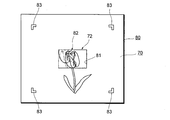
図10は,電子ビュー・ファインダ65の表示画面に表示される電子ビュー・ファインダ画像80の一例である。
電子ビュー・ファインダ画像80には,ほぼ中心に一つのAFターゲット領域81が形成されている。このAFターゲット領域81に固体電子撮像素子41により撮像された被写体像82が表示されている(撮像により得られた画像であることが分るように,図10では鎖線で示されている)。AFターゲット領域82の周りの領域はマスク領域85である。マスク領域85は,固体電子撮像素子41により撮像された被写体像のうち,AFターゲット領域82に表示されていない画像をマスクするものである。また,電子ビュー・ファインダ画像80の四隅には撮像範囲を示す視野枠83が表示されている。マスク領域85および視野枠83を示すデータはメモリ46に格納されており,それらのデータがCPU47によってメモリ46から読み出され,LCDドライバ36に与えられることにより,マスク領域85および視野枠83が表示される。
図11は,接眼窓11から見えるファインダ画像の一例である。
OVFシャッタ62が開いており,かつ電子ビュー・ファインダ65に電子ビュー・ファインダ画像80が表示されていると,図9に示す光学的な被写体像70上に,図10に示す電子ビュー・ファインダ画像80が重ねられた画像が接眼窓11から見える。
上述したようにレンズ鏡筒1の光軸C2とファインダ装置60の光軸C3との間には視差があるが,電子ビュー・ファインダ65に表示される被写体像82は視差補正が行われるように画像シフト回路35によって電子ビュー・ファインダ65の表示位置がシフトされる。このために,AFターゲット領域81内の被写体像82にピントが合っていれば光学的な被写体像72に重畳している被写体像82とは一致し,AFターゲット領域81内の被写体像82にピントが合っていなければ光学的な被写体像72に重畳している被写体像82とはずれが生じる。光学的な被写体像72と撮像された被写体像82とのずれに応じて,フォーカス・リング32を操作することによりマニュアル・フォーカスのピント合わせを実現できる。
図12は,フォーカシング処理手順を示すフローチャートである。
上述のようにフォーカス設定レバー20により二重像合致式マニュアル・フォーカス・モードが設定されているかどうかが確認される(図12ステップ90)。オート・フォーカスが設定されており,二重像合致式マニュアル・フォーカス・モードが設定されていなければ(図12ステップ90でNO),電子ビュー・ファインダ65の表示はオフされる(図12ステップ103)。電子ビュー・ファインダ65がオフされるので,ユーザは,ディジタル・カメラ1の背面に形成されている液晶表示画面12に表示されている被写体像を見ながら撮影することとなろう。もっとも,オート・フォーカスが設定された場合にOVFシャッタ62を閉じ,電子ビュー・ファインダ65に被写体像を表示するようにしてもよい。電子ビュー・ファインダ65に表示される被写体像を接眼窓11から覗きながら撮影できるようになる。
フォーカス設定レバー20により二重像合致式マニュアル・フォーカスが設定されていると(図12ステップ90でYES),OVFシャッタ62は開かれる。光学的な被写体像をファインダ装置60から見ることができるようになる。
ユーザは,ファインダ装置60の接眼窓11を覗き,光学的な被写体像を見ながら,フォーカス・リング32を操作する(図12ステップ91)。フォーカス・リング32の回転量がエンコーダ33によって検出され(図12ステップ92),フォーカス・レンズ群31が合焦するディジタル・カメラ1から被写体までの距離が算出される(図12ステップ93)。フォーカス・リング32の回転量とフォーカス・レンズ群31が合焦するディジタル・カメラ1から被写体までの距離との関係は,ディジタル・カメラ1の製造工程において予め検出されており,それらの関係を示すデータは距離検出回路34内のメモリ(図示略)に格納されている。それらの関係を示すデータを利用してフォーカス・レンズ群31の回転量からフォーカス・レンズ群31が合焦するディジタル・カメラ1から被写体までの距離が算出されることとなる。
算出された距離に応じて,視差補正のための画像シフト量が算出される(図12ステップ94)。フォーカス・レンズ群31が合焦するディジタル・カメラ1から被写体までの距離とシフト量との関係についても,ディジタル・カメラの製造工程において予め算出され,記憶されているのはいうまでもない。
固体電子撮像素子41によって撮像された被写体像が,フォーカス・リング31の回転量に応じて算出された画像シフト量の分だけずらされて電子ビュー・ファインダ65の表示画面に表示される(図12ステップ95)。上述のように,AFターゲット領域81内の被写体像82は,ピントが合っていなければ光学的な被写体像72とずれ,ピントが合っていれば光学的な被写体像72と一致する。ファインダ装置60は,いわゆる二重像合致式のものとなる。たとえば,図8を参照して,被写体が距離D2の距離にある被写体OB2であったにも関わらず,距離D1または距離D3にある被写体OB1または被写体OB3に合焦するようにフォーカス・リング32が操作されたものとする。するとファインダ装置60を覗くユーザには二重にずれた被写体像が見える。フォーカス・リング32を操作することにより,距離D2にある被写体OB2に合焦するようにフォーカス・リング32が操作されると,ファインダ装置60を覗くユーザには画像ずれの無い被写体像が見える。
ディジタル・カメラ1に手振れがあり,手振れセンサ51によりディジタル・カメラ1の角速度が検出されている。検出された角速度が第1のしきい値以上であると(図12ステップ96でYES),撮像した被写体像はぶれてしまうので,ピントがあっていても電子ビュー・ファインダ65に表示されるAFターゲット領域81内の被写体像82と光学的な被写体像72とは一致しない。このために電子ビュー・ファインダ65の表示画面の表示はオフとされる(図12ステップ97)。角速度が第1のしきい値以下となると(図12ステップ98でYES),再びステップ91からの処理が繰り返され,電子ビュー・ファインダ65の表示画面にAFターゲット領域81内の画像82が表示される。手振れがあり,角速度がしきい値以上の場合に(図12ステップ96でYES),電子ビュー・ファインダ65の表示画面の表示がオフとなると,液晶表示画面12に表示される被写体像を見ながらマニュアル・フォーカスを行うことが多いであろうから,角速度がしきい値以上の場合であっても(図12ステップ96でYES),OVFシャッタ62をオフにし,接眼窓11から電子ビュー・ファインダ65に表示される被写体像を見ることができるようにするとよい。この場合には,電子ビュー・ファインダ65には図10に示すようにAFターゲット領域81内の画像だけでなく,撮像した被写体像の全体が表示されることとなろう。手振れがあった場合でも接眼窓11を覗きながら,電子ビュー・ファインダ65の表示画面に表示される被写体像を見ながらマニュアル・フォーカスを続行できる。
検出された角速度が第1のしきい値未満であると(図12ステップ96でNO),ディジタル・カメラ1の手振れは起きていないので,被写体の移動量がしきい値以上かどうかが確認される(図13ステップ99)。上述のように移動量算出回路52により,被写体の移動量が算出される。撮像した被写体像の中に動きのある被写体が複数存在した場合には,最も動きの大きい被写体について移動量を算出してもよいし,AFターゲット領域81内に存在していた被写体についての移動量を算出してもよい。算出された被写体の移動量が第2のしきい値未満であれば,手振れも少なく,かつ動きの速い被写体も存在していないので上述した二重像合致式のマニュアル・フォーカスによりピントが合わせられる。
被写体移動量が第2のしきい値以上であると(図13ステップ99でYES),被写体の移動速度が速いので二重像合致式によるマニュアル・フォーカスには適さない。このために,電子ビュー・ファインダ65の表示画面への表示がオフされる。ユーザは,液晶表示装置の表示画面12に表示される被写体像を見ながらマニュアル・フォーカス処理を行うこととなろう。もっとも,上述したのと同様に,OVFシャッタ62をオフし,電子ビュー・ファインダ65の表示画面に撮像した被写体像全体を表示するようにしてもよい。電子ビュー・ファインダ65の表示画面に表示された被写体像全体を接眼窓11から覗きながら,マニュアル・フォーカスを実現できる。被写体移動量が第2のしきい値未満であるとステップ96,98の処理が繰り返されるが,ステップ91の処理から繰り返してもよい。
撮像モードがオフとされなければ(図13ステップ101でNO),被写体移動量がしきい値以下であれば(図13ステップ102でYES),図12ステップ91からの処理が再び繰り返される。
上述の実施例では,角速度または被写体の移動量がしきい値以上であれば,二重像合致式マニュアル・フォーカス・モードが設定されていても電子ビュー・ファインダ65の表示画面への表示をオフにする,あるいはOVFシャッタ62を閉じて電子ビュー・ファインダ65に撮像した被写体像全体を表示するようにしているが,マニュアル・フォーカスの設定自体を解除してオート・フォーカスとなるようにしてもよい。オート・フォーカスとした場合,OVFシャッタ62を開いて電子ビュー・ファインダ65の表示画面の表示をオフし,接眼窓11から光学的な被写体像を覗きながらカメラ・アングルを決定してもよいし,OVFシャッタ62を閉じて電子ビュー・ファインダ65に撮像した被写体像を表示し,電子ビュー・ファインダ65に表示される被写体像を接眼窓11から見ながらカメラ・アングルを決定してもよい。もっとも,接眼窓11から覗かずに液晶表示装置12の表示画面に表示される被写体像を見ながらカメラ・アングルを決定してもよいのはいうまでもない。
所望の被写体にピントがあったことにより,シャッタ・レリーズ・ボタンがオンされることにより,撮像された被写体像を表わす画像データがメモリ・カード50に記録される。
図14は,変形例を示すもので,AFターゲット枠サイズ設定画像の一例である。
ディジタル・カメラ1に含まれているボタン類のうちのメニュー/OKボタン15を利用してメニュー表示画面が選択されると,AFターゲット枠サイズ設定メニューの選択が可能となる。AFターゲット枠サイズ設定メニューが選択されると,図14に示すAFターゲット枠サイズ設定画像が液晶表示画面12に表示される。
AFターゲット枠サイズ設定画像の下部には横方向に伸びたサイズ設定バー106が形成されている。このサイズ設定バー101上を横方向に自在に動くスライダ101も形成されている。AFターゲット枠サイズ設定メニューが設定されると,ディジタル・カメラ1に含まれているボタンのうち,所定のボタンを操作することにより,サイズ設定バー106上をスライダ105が左右に動く。スライダ105が左側に動くにつれてAFターゲット領域81の大きさは小さくなり,スライダ105が右側に動くにつれてAFターゲット領域81の大きさは鎖線で示すように大きくなる。このようにAFターゲット領域81の大きさを所望の大きさに設定することもできる。
図15は,他の変形例を示すもので,AFターゲット濃淡設定画像である。
上述したAFターゲット枠の設定と同様に,ディジタル・カメラ1に含まれているボタン類のうちのメニュー/OKボタン15を利用してメニュー表示画面が選択されると,AFターゲット濃淡設定メニューの選択が可能となる。AFターゲット濃淡設定メニューが選択されると,図15に示す設定画像が液晶表示画面12に表示される。
AFターゲット濃淡設定画像の下部にも横方向に伸びた濃淡設定バー108が形成されている。この濃淡設定バー108上を横方向に自在に動くスライダ107も形成されている。濃淡設定メニューが設定されると,ディジタル・カメラ1に含まれているボタンのうち,所定のボタンを操作することにより,濃淡設定バー108上をスライダ107が左右に動く。スライダ107が左側に動くにつれてAFターゲット領域81内に表示される被写体像82は薄くなり,スライダ102が右側に動くにつれてAFターゲット領域81内に表示される被写体像82は濃くなる。このように,AFターゲット領域81内に表示される被写体像の濃淡を設定することもできる。
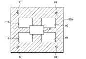
図16は,さらに,他の変形例を示すもので,電子ビュー・ファインダ65の表示画面に表示される電子ビュー・ファインダ画像80Aの一例である。図10に示す電子ビュー・ファインダ画像80に対応している。
図10に示した例では,ほぼ中央に一つのAFターゲット領域81が設定されているが,図16に示す例では,ほぼ中央にAFターゲット領域81が設定されているほかに,そのAFターゲット領域81の周りに四つのAFターゲット領域111~114が設定されている。
このように複数のAFターゲット領域81,111~114が設定されることにより,所望のターゲット枠内の被写体についてピントを合わせることができるようになる。
複数のAFターゲット領域81,111~114が設定される場合には,上述したのと同様に,メニュー表示画面を設定し,AFターゲット領域設定メニューを選択する。すると,設定するAFターゲットの数を入力し,かつAFターゲット領域を設定する位置を入力できるようになる。必要であれば,表示画面12にタッチ・パネル等を設け,タッチ・パネル上でAFターゲット領域の位置を規定するようにしてもよい。もっとも,図15に示すように5つのAFターゲット領域81,111~114と図10に示すように1つのAFターゲット領域81とのいずれを設定できるように予め規定しておき,ユーザがいずれかを選択するようにしてもよい。これらの複数のAFターゲット領域81,111~114内に固体電子撮像素子41によって撮像された被写体像のうち対応する画像部分が表示されるのはいうまでもない。
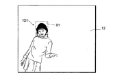
図17は,さらに他の変形例を示すもので,撮像された被写体像の一例である。
被写体を撮像することにより,顔画像121が検出される。検出された顔画像121の領域がAFターゲット領域81に設定される。顔検出は,CPU47により実行されればよい。顔の部分にピントが合うようになる。
2 レンズ鏡筒
3 対物窓
11 接眼窓
31 フォーカス・レンズ群
32 フォーカス・リング
34 距離検出回路
35 画像シフト回路
41 固体電子撮像素子
51 手振れセンサ
52 移動量算出回路
60 ファインダ装置
63 プリズム(偏向装置)
65 電子ビュー・ファインダ(表示装置)
3 対物窓
11 接眼窓
31 フォーカス・レンズ群
32 フォーカス・リング
34 距離検出回路
35 画像シフト回路
41 固体電子撮像素子
51 手振れセンサ
52 移動量算出回路
60 ファインダ装置
63 プリズム(偏向装置)
65 電子ビュー・ファインダ(表示装置)
Claims (11)
- フォーカス・レンズが内蔵され,かつ回転自在なフォーカス・リングが周囲に設けられており,上記フォーカス・リングの回転に応じて上記フォーカス・レンズの位置を調整するレンズ鏡筒,
上記フォーカス・レンズによって結像する被写体を撮像し,被写体像を表わす画像データを出力する固体電子撮像装置,
上記固体電子撮像装置から出力された画像データによって表わされる被写体像のうち,所望のAFターゲット領域内の画像を表示画面に表示する表示装置,
カメラの前面に形成され,被写体に向く対物窓および上記対物窓を通して見える光学的な被写体像を覗く接眼窓を備えたファインダ装置,
上記対物窓と上記接眼窓との間に設けられ,上記表示装置の表示画面に表示されているAFターゲット領域内の画像を上記接眼窓に導く偏向装置,
上記AFターゲット領域内の画像が非合焦であれば上記対物窓を通して見える光学的な被写体像と上記AFターゲット領域内の画像とがずれるように上記表示画面にAFターゲット領域内の画像を表示し,上記AFターゲット領域内の画像が合焦であれば上記対物窓を通して見える光学的な被写体像と上記AFターゲット領域内の画像とが一致するように上記表示画面にAFターゲット領域内の画像を表示するように上記表示装置を制御する第1の表示制御手段,ならびに
カメラまたは被写体がしきい値以上で動いているかどうかを判定する動き判定手段,
上記動き判定手段により,カメラまたは被写体がしきい値以上で動いていると判定されたことに応じて,上記第1の表示制御手段の制御により上記表示装置の表示画面に表示される画像を消去するように上記表示装置を制御する第2の表示制御手段,
を備えたカメラ。 - 上記第1の表示制御手段は,
上記フォーカス・リングの回転量を検出する回転量検出手段を備え,
上記回転量検出手段によって検出された回転量にもとづいて,上記AFターゲット領域内の画像が非合焦であれば上記対物窓を通して見える光学的な被写体像と上記AFターゲット領域内の画像とが少なくとも横方向にずれるように上記表示画面にAFターゲット領域内の画像を表示し,上記AFターゲット領域内の画像が合焦であれば上記対物窓を通して見える光学的な被写体像と上記AFターゲット領域内の画像とが一致するように上記表示画面にAFターゲット領域内の画像を表示するように上記表示装置を制御するものである,
請求項1に記載のカメラ。 - 上記第1の表示制御手段は,
上記回転量検出手段によって検出された回転量にもとづいて,上記AFターゲット領域内の画像が非合焦であれば上記対物窓を通して見える光学的な被写体像と上記AFターゲット領域内の画像とが上記レンズ鏡筒の光軸と上記ファインダ装置の光軸とを結ぶ軸上をずれるように上記表示画面にAFターゲット領域内の画像を表示し,上記AFターゲット領域内の画像が合焦であれば上記対物窓を通して見える光学的な被写体像と上記AFターゲット領域内の画像とが一致するように上記表示画面にAFターゲット領域内の画像を表示するように上記表示装置を制御するものである,
請求項2に記載のカメラ。 - 上記第1の表示制御手段は,
フォーカス・リングの回転に応じて,上記AFターゲット領域内の画像を少なくとも横方向に移動させるとともに,上記フォーカス・レンズの合焦位置が被写体までの距離に一致した場合に上記対物窓を通して見える光学的な被写体像と上記AFターゲット領域内の画像とが一致するように上記表示画面にAFターゲット領域内の画像を表示するように表示装置を制御するものである,
請求項1から3のうち,いずれか一項に記載のカメラ。 - 上記第1の表示制御手段は,
上記フォーカス・リングの回転量を検出する回転量検出手段,および上記回転量検出手段によって検出された回転量にもとづいてカメラの前方のどの位の距離にある被写体について合焦するかを算出する距離算出手段を備え,
上記距離算出手段において算出された距離にある被写体を上記ファインダ装置の上記対物窓を通して見える光学的な被写体像と,その被写体を上記固体電子撮像装置によって撮像することにより上記表示装置の上記表示画面に表示されているAFターゲット領域の画像と,を一致させるものである,
請求項1から4のうち,いずれか一項に記載のカメラ。 - 上記第1の表示制御手段は,
固体電子撮像装置の光軸と上記ファインダ装置の光軸とのずれによる,上記対物窓を通して見える光学的な被写体像と上記AFターゲット領域内の画像とのずれを補正して,上記AFターゲット領域内の画像を上記表示画面に表示するものである,
請求項1から5のうち,いずれか一項に記載のカメラ。 - 上記第1の表示制御手段は,
固体電子撮像装置の光軸と上記ファインダ装置の光軸とのずれによる,上記対物窓を通して見える光学的な被写体像と上記AFターゲット領域内の画像とのずれを,上記距離算出手段によって算出された距離に応じた補正分を補正して,上記AFターゲット領域内の画像を上記表示画面に表示するものである,
請求項6に記載のカメラ。 - 上記AFターゲット領域の位置,大きさおよび数のうち少なくとも一つを設定する第1のAFターゲット領域設定手段,
をさらに備えた請求項1から7のうち,いずれか一項に記載のカメラ。 - 上記AFターゲット領域内の画像の明るさまたは濃度の少なくとも一方を設定する第2のAFターゲット領域設定手段,
をさらに備えた請求項1から8のうち,いずれか一項に記載のカメラ。 - 上記固体電子撮像装置によって撮像された被写体像に含まれる顔の領域を検出する顔検出手段,および
上記顔検出手段によって検出された顔の領域をAFターゲット領域に設定する第3のAFターゲット領域設定手段,
をさらに備えた請求項1から9のうち,いずれか一項に記載のカメラ。 - フォーカス・レンズが内蔵され,かつ回転自在なフォーカス・リングが周囲に設けられており,上記フォーカス・リングの回転に応じて上記フォーカス・レンズの位置を調整するレンズ鏡筒およびカメラの前面に形成され,被写体に向く対物窓および上記対物窓を通して見える光学的な被写体像を覗く接眼窓を備えたファインダ装置を備えたカメラの動作制御方法において,
固体電子撮像装置が,上記フォーカス・レンズによって結像する被写体を撮像し,被写体像を表わす画像データを出力し,
表示装置が,上記固体電子撮像装置から出力された画像データによって表わされる被写体像のうち,所望のAFターゲット領域内の画像を表示画面に表示し,
偏向装置が,上記対物窓と上記接眼窓との間に設けられ,上記表示装置の表示画面に表示されているAFターゲット領域内の画像を上記接眼窓に導き,
第1の表示制御手段が,上記AFターゲット領域内の画像が非合焦であれば上記対物窓を通して見える光学的な被写体像と上記AFターゲット領域内の画像とがずれるように上記表示画面にAFターゲット領域内の画像を表示し,上記AFターゲット領域内の画像が合焦であれば上記対物窓を通して見える光学的な被写体像と上記AFターゲット領域内の画像とが一致するように上記表示画面にAFターゲット領域内の画像を表示するように上記表示装置を制御し,
動き判定手段が,カメラまたは被写体がしきい値以上で動いているかどうかを判定し,
第2の表示制御手段が,上記動き判定手段により,カメラまたは被写体がしきい値以上で動いていると判定されたことに応じて,上記第1の表示制御手段の制御により上記表示装置の表示画面に表示される画像を消去するように上記表示装置を制御する,
を備えたカメラ。
Priority Applications (3)
| Application Number | Priority Date | Filing Date | Title |
|---|---|---|---|
| JP2014526804A JP5736514B2 (ja) | 2012-07-24 | 2013-06-03 | カメラおよびその動作制御方法 |
| CN201380039370.XA CN104508551B (zh) | 2012-07-24 | 2013-06-03 | 相机及其动作控制方法 |
| US14/604,422 US9264617B2 (en) | 2012-07-24 | 2015-01-23 | Camera and method of controlling operation of same |
Applications Claiming Priority (2)
| Application Number | Priority Date | Filing Date | Title |
|---|---|---|---|
| JP2012163890 | 2012-07-24 | ||
| JP2012-163890 | 2012-07-24 |
Related Child Applications (1)
| Application Number | Title | Priority Date | Filing Date |
|---|---|---|---|
| US14/604,422 Continuation US9264617B2 (en) | 2012-07-24 | 2015-01-23 | Camera and method of controlling operation of same |
Publications (1)
| Publication Number | Publication Date |
|---|---|
| WO2014017174A1 true WO2014017174A1 (ja) | 2014-01-30 |
Family
ID=49996992
Family Applications (1)
| Application Number | Title | Priority Date | Filing Date |
|---|---|---|---|
| PCT/JP2013/065369 Ceased WO2014017174A1 (ja) | 2012-07-24 | 2013-06-03 | カメラおよびその動作制御方法 |
Country Status (4)
| Country | Link |
|---|---|
| US (1) | US9264617B2 (ja) |
| JP (1) | JP5736514B2 (ja) |
| CN (1) | CN104508551B (ja) |
| WO (1) | WO2014017174A1 (ja) |
Families Citing this family (7)
| Publication number | Priority date | Publication date | Assignee | Title |
|---|---|---|---|---|
| JP5736514B2 (ja) * | 2012-07-24 | 2015-06-17 | 富士フイルム株式会社 | カメラおよびその動作制御方法 |
| WO2014017173A1 (ja) * | 2012-07-24 | 2014-01-30 | 富士フイルム株式会社 | カメラおよびその動作制御方法 |
| JP5736515B2 (ja) * | 2012-07-24 | 2015-06-17 | 富士フイルム株式会社 | カメラおよびその動作制御方法 |
| JP6539091B2 (ja) * | 2015-04-09 | 2019-07-03 | キヤノン株式会社 | 撮像装置およびその制御方法 |
| US20190098228A1 (en) * | 2015-05-22 | 2019-03-28 | Chad-Affonso Wathington | Superimposing an image on an image of an object being photographed |
| KR102345652B1 (ko) * | 2015-06-26 | 2021-12-30 | 삼성전자주식회사 | 뷰 파인더 장치 및 그 동작 방법 |
| CN111698421B (zh) * | 2020-06-09 | 2021-12-17 | 展讯通信(上海)有限公司 | 一种图像处理方法、装置及计算机可读存储介质 |
Citations (4)
| Publication number | Priority date | Publication date | Assignee | Title |
|---|---|---|---|---|
| JP2005198035A (ja) * | 2004-01-07 | 2005-07-21 | Fuji Photo Film Co Ltd | デジタルカメラ |
| JP2007298672A (ja) * | 2006-04-28 | 2007-11-15 | Fujinon Corp | レンズ装置 |
| WO2012035877A1 (ja) * | 2010-09-17 | 2012-03-22 | 富士フイルム株式会社 | 撮影装置 |
| JP2012085261A (ja) * | 2010-09-17 | 2012-04-26 | Fujifilm Corp | 撮像装置、ファインダ及びその表示方法 |
Family Cites Families (20)
| Publication number | Priority date | Publication date | Assignee | Title |
|---|---|---|---|---|
| JP2000258834A (ja) | 1999-03-04 | 2000-09-22 | Fuji Photo Optical Co Ltd | カメラのファインダ |
| US6556791B1 (en) * | 1999-12-21 | 2003-04-29 | Eastman Kodak Company | Dual channel optical imaging system |
| JP4452681B2 (ja) | 2005-12-13 | 2010-04-21 | 学校法人西沢学園 | Ccdを用いた像合致式距離計および距離計付きカメラ並びに撮影システム |
| JP5058834B2 (ja) | 2008-01-22 | 2012-10-24 | キヤノン株式会社 | 撮像装置 |
| JP2011135490A (ja) | 2009-12-25 | 2011-07-07 | Seiko Epson Corp | デジタルカメラおよびその製造方法 |
| JP2012065294A (ja) * | 2010-09-17 | 2012-03-29 | Fujifilm Corp | ハイブリッド型ファインダ装置 |
| JP5512878B2 (ja) * | 2011-03-04 | 2014-06-04 | 富士フイルム株式会社 | 撮影装置及び表示制御方法 |
| CN103842903B (zh) * | 2011-09-30 | 2015-06-03 | 富士胶片株式会社 | 成像设备、成像方法以及程序 |
| WO2013136907A1 (ja) * | 2012-03-15 | 2013-09-19 | 富士フイルム株式会社 | 撮像装置及び電子ビューファインダ表示方法 |
| JP5635211B2 (ja) * | 2012-03-28 | 2014-12-03 | 富士フイルム株式会社 | 撮像装置 |
| CN104365089B (zh) * | 2012-06-07 | 2018-10-26 | 富士胶片株式会社 | 摄像装置及图像显示方法 |
| JP5723487B2 (ja) * | 2012-06-29 | 2015-05-27 | 富士フイルム株式会社 | カメラおよびその動作制御方法 |
| JP5753948B2 (ja) * | 2012-06-29 | 2015-07-22 | 富士フイルム株式会社 | カメラおよびその動作制御方法 |
| JP5845350B2 (ja) * | 2012-06-29 | 2016-01-20 | 富士フイルム株式会社 | カメラおよびその動作制御方法 |
| JP5723488B2 (ja) * | 2012-07-20 | 2015-05-27 | 富士フイルム株式会社 | カメラおよびその動作制御方法 |
| WO2014013797A1 (ja) * | 2012-07-20 | 2014-01-23 | 富士フイルム株式会社 | カメラおよびその動作制御方法 |
| JP5736514B2 (ja) * | 2012-07-24 | 2015-06-17 | 富士フイルム株式会社 | カメラおよびその動作制御方法 |
| JP5736515B2 (ja) * | 2012-07-24 | 2015-06-17 | 富士フイルム株式会社 | カメラおよびその動作制御方法 |
| WO2014045689A1 (ja) * | 2012-09-19 | 2014-03-27 | 富士フイルム株式会社 | 画像処理装置、撮像装置、プログラム及び画像処理方法 |
| US9509913B2 (en) * | 2013-06-18 | 2016-11-29 | Olympus Corporation | Image pickup apparatus, method of controlling image pickup apparatus, image pickup apparatus system, and image pickup control program stored in storage medium of image pickup apparatus |
-
2013
- 2013-06-03 JP JP2014526804A patent/JP5736514B2/ja not_active Expired - Fee Related
- 2013-06-03 CN CN201380039370.XA patent/CN104508551B/zh not_active Expired - Fee Related
- 2013-06-03 WO PCT/JP2013/065369 patent/WO2014017174A1/ja not_active Ceased
-
2015
- 2015-01-23 US US14/604,422 patent/US9264617B2/en not_active Expired - Fee Related
Patent Citations (4)
| Publication number | Priority date | Publication date | Assignee | Title |
|---|---|---|---|---|
| JP2005198035A (ja) * | 2004-01-07 | 2005-07-21 | Fuji Photo Film Co Ltd | デジタルカメラ |
| JP2007298672A (ja) * | 2006-04-28 | 2007-11-15 | Fujinon Corp | レンズ装置 |
| WO2012035877A1 (ja) * | 2010-09-17 | 2012-03-22 | 富士フイルム株式会社 | 撮影装置 |
| JP2012085261A (ja) * | 2010-09-17 | 2012-04-26 | Fujifilm Corp | 撮像装置、ファインダ及びその表示方法 |
Also Published As
| Publication number | Publication date |
|---|---|
| JPWO2014017174A1 (ja) | 2016-07-07 |
| US20150130955A1 (en) | 2015-05-14 |
| CN104508551B (zh) | 2016-01-20 |
| US9264617B2 (en) | 2016-02-16 |
| CN104508551A (zh) | 2015-04-08 |
| JP5736514B2 (ja) | 2015-06-17 |
Similar Documents
| Publication | Publication Date | Title |
|---|---|---|
| JP5736514B2 (ja) | カメラおよびその動作制御方法 | |
| US9131157B2 (en) | Camera and method of controlling operation of same | |
| US9172881B2 (en) | Camera and method of controlling operation of same | |
| JP5736515B2 (ja) | カメラおよびその動作制御方法 | |
| JP5753948B2 (ja) | カメラおよびその動作制御方法 | |
| US10564391B2 (en) | Imaging device and control method therefor | |
| US9258488B2 (en) | Camera and method of controlling operation of same | |
| US9143694B2 (en) | Camera and method of controlling operation of same | |
| JP5723489B2 (ja) | カメラおよびその動作制御方法 | |
| US10567662B2 (en) | Imaging device and control method therefor using shift direction calculation |
Legal Events
| Date | Code | Title | Description |
|---|---|---|---|
| 121 | Ep: the epo has been informed by wipo that ep was designated in this application |
Ref document number: 13823543 Country of ref document: EP Kind code of ref document: A1 |
|
| DPE2 | Request for preliminary examination filed before expiration of 19th month from priority date (pct application filed from 20040101) | ||
| ENP | Entry into the national phase |
Ref document number: 2014526804 Country of ref document: JP Kind code of ref document: A |
|
| NENP | Non-entry into the national phase |
Ref country code: DE |
|
| 122 | Ep: pct application non-entry in european phase |
Ref document number: 13823543 Country of ref document: EP Kind code of ref document: A1 |