WO2014017014A1 - Egrシステムおよび排気熱交換システム - Google Patents
Egrシステムおよび排気熱交換システム Download PDFInfo
- Publication number
- WO2014017014A1 WO2014017014A1 PCT/JP2013/003853 JP2013003853W WO2014017014A1 WO 2014017014 A1 WO2014017014 A1 WO 2014017014A1 JP 2013003853 W JP2013003853 W JP 2013003853W WO 2014017014 A1 WO2014017014 A1 WO 2014017014A1
- Authority
- WO
- WIPO (PCT)
- Prior art keywords
- heat medium
- cooling water
- exhaust
- egr
- temperature
- Prior art date
- Legal status (The legal status is an assumption and is not a legal conclusion. Google has not performed a legal analysis and makes no representation as to the accuracy of the status listed.)
- Ceased
Links
Images



Classifications
-
- F—MECHANICAL ENGINEERING; LIGHTING; HEATING; WEAPONS; BLASTING
- F28—HEAT EXCHANGE IN GENERAL
- F28D—HEAT-EXCHANGE APPARATUS, NOT PROVIDED FOR IN ANOTHER SUBCLASS, IN WHICH THE HEAT-EXCHANGE MEDIA DO NOT COME INTO DIRECT CONTACT
- F28D21/00—Heat-exchange apparatus not covered by any of the groups F28D1/00 - F28D20/00
- F28D21/0001—Recuperative heat exchangers
- F28D21/0003—Recuperative heat exchangers the heat being recuperated from exhaust gases
-
- F—MECHANICAL ENGINEERING; LIGHTING; HEATING; WEAPONS; BLASTING
- F02—COMBUSTION ENGINES; HOT-GAS OR COMBUSTION-PRODUCT ENGINE PLANTS
- F02M—SUPPLYING COMBUSTION ENGINES IN GENERAL WITH COMBUSTIBLE MIXTURES OR CONSTITUENTS THEREOF
- F02M26/00—Engine-pertinent apparatus for adding exhaust gases to combustion-air, main fuel or fuel-air mixture, e.g. by exhaust gas recirculation [EGR] systems
- F02M26/13—Arrangement or layout of EGR passages, e.g. in relation to specific engine parts or for incorporation of accessories
- F02M26/22—Arrangement or layout of EGR passages, e.g. in relation to specific engine parts or for incorporation of accessories with coolers in the recirculation passage
- F02M26/29—Constructional details of the coolers, e.g. pipes, plates, ribs, insulation or materials
- F02M26/32—Liquid-cooled heat exchangers
-
- F—MECHANICAL ENGINEERING; LIGHTING; HEATING; WEAPONS; BLASTING
- F02—COMBUSTION ENGINES; HOT-GAS OR COMBUSTION-PRODUCT ENGINE PLANTS
- F02M—SUPPLYING COMBUSTION ENGINES IN GENERAL WITH COMBUSTIBLE MIXTURES OR CONSTITUENTS THEREOF
- F02M26/00—Engine-pertinent apparatus for adding exhaust gases to combustion-air, main fuel or fuel-air mixture, e.g. by exhaust gas recirculation [EGR] systems
- F02M26/13—Arrangement or layout of EGR passages, e.g. in relation to specific engine parts or for incorporation of accessories
- F02M26/22—Arrangement or layout of EGR passages, e.g. in relation to specific engine parts or for incorporation of accessories with coolers in the recirculation passage
- F02M26/33—Arrangement or layout of EGR passages, e.g. in relation to specific engine parts or for incorporation of accessories with coolers in the recirculation passage controlling the temperature of the recirculated gases
-
- F—MECHANICAL ENGINEERING; LIGHTING; HEATING; WEAPONS; BLASTING
- F28—HEAT EXCHANGE IN GENERAL
- F28D—HEAT-EXCHANGE APPARATUS, NOT PROVIDED FOR IN ANOTHER SUBCLASS, IN WHICH THE HEAT-EXCHANGE MEDIA DO NOT COME INTO DIRECT CONTACT
- F28D7/00—Heat-exchange apparatus having stationary tubular conduit assemblies for both heat-exchange media, the media being in contact with different sides of a conduit wall
- F28D7/0066—Multi-circuit heat-exchangers, e.g. integrating different heat exchange sections in the same unit or heat-exchangers for more than two fluids
- F28D7/0075—Multi-circuit heat-exchangers, e.g. integrating different heat exchange sections in the same unit or heat-exchangers for more than two fluids with particular circuits for the same heat exchange medium, e.g. with the same heat exchange medium flowing through sections having different heat exchange capacities or for heating or cooling the same heat exchange medium at different temperatures
-
- F—MECHANICAL ENGINEERING; LIGHTING; HEATING; WEAPONS; BLASTING
- F28—HEAT EXCHANGE IN GENERAL
- F28D—HEAT-EXCHANGE APPARATUS, NOT PROVIDED FOR IN ANOTHER SUBCLASS, IN WHICH THE HEAT-EXCHANGE MEDIA DO NOT COME INTO DIRECT CONTACT
- F28D7/00—Heat-exchange apparatus having stationary tubular conduit assemblies for both heat-exchange media, the media being in contact with different sides of a conduit wall
- F28D7/16—Heat-exchange apparatus having stationary tubular conduit assemblies for both heat-exchange media, the media being in contact with different sides of a conduit wall the conduits being arranged in parallel spaced relation
Definitions
- the present disclosure relates to an EGR system and an exhaust heat exchange system for exchanging heat between exhaust gas discharged from an internal combustion engine and a heat medium.
- an EGR cooler for cooling the exhaust and an EGR valve for adjusting the passage opening degree of the EGR passage are provided in the EGR passage communicating the exhaust passage and the intake passage of the engine.
- the EGR cooler is designed so that the high-temperature exhaust is cooled by engine cooling water so that the exhaust temperature falls below a predetermined temperature. That is, the EGR cooler cools the exhaust gas with cooling water around 90 ° C. even under the most severe engine load conditions where the EGR valve is fully opened, so that the exhaust temperature at the outlet of the EGR cooler becomes a predetermined temperature.
- the thermally severe engine load condition means that the exhaust temperature is the highest and the exhaust flow rate is the maximum flow rate.
- the exhaust flow rate is low, the exhaust temperature flowing into the EGR cooler is often low, and the cooling water temperature is also low.
- the exhaust temperature when passing through the EGR valve from the outlet of the EGR cooler is approximately the same as the cooling water temperature (70 ° C. to 90 ° C.), PM may be easily deposited.
- This indication aims at providing the EGR system and exhaust heat exchange system which can control the fall of the heat exchange efficiency of the heat exchanger by adhesion of PM, and the increase in ventilation resistance in view of the above-mentioned point.
- the EGR is provided in an EGR passage that connects the exhaust passage and the intake passage of the internal combustion engine, and cools the exhaust by performing heat exchange between the exhaust of the internal combustion engine and the heat medium.
- the EGR cooler includes a heat medium flow path through which the heat medium flows, a heat medium inlet that allows the heat medium to flow into the heat medium flow path, and first heat that causes the heat medium to flow out from the heat medium flow path.
- a heat medium circuit switching device that switches between a first heat medium circuit that causes the heat medium to flow out from the first heat medium outlet and a second heat medium circuit that causes the heat medium that has flowed in from the heat medium inlet to flow out from the second heat medium outlet is provided. It is characterized by
- the first heat medium outlet is arranged downstream of the second heat medium outlet in the flow direction of the exhaust gas, and the first heat that causes the heat medium flowing in from the heat medium inlet to flow out from the first heat medium outlet is arranged.
- the heat medium circuit switching device causes the heat medium circuit switching device to When switching to the second heat medium circuit that causes the inflowing heat medium to flow out from the second heat medium outlet, the downstream region of the exhaust flow of the second heat medium outlet in the EGR cooler, that is, the second heat medium outlet and the first heat medium The heat medium between the outlets does not circulate.
- An EGR cooler that is provided in an EGR passage that connects the exhaust passage and the intake passage of the internal combustion engine, cools the exhaust gas by exchanging heat between the exhaust gas of the internal combustion engine and the heat medium, and a passage of the EGR passage
- an EGR cooler is provided with a first EGR cooler and a second EGR cooler disposed downstream of the first EGR cooler in the exhaust flow direction. The valve may be provided between the first EGR cooler and the second EGR cooler.
- the first EGR cooler and the second EGR cooler disposed downstream of the first EGR cooler in the exhaust flow direction as the EGR cooler, the first EGR cooler and the second EGR cooler of the first EGR cooler are provided.
- the heat medium is allowed to flow only in the cooler, the heat medium does not circulate in the second EGR cooler.
- the second EGR cooler heat exchange is hardly performed between the exhaust and the heat medium, and the exhaust is not cooled. Therefore, since it can suppress that a 2nd EGR cooler becomes low temperature, it can suppress that PM accumulates on a 2nd EGR cooler. As a result, it is possible to suppress a decrease in heat exchange efficiency of the EGR cooler and an increase in ventilation resistance due to the adhesion of PM.
- the exhaust before being cooled by the second EGR cooler can be caused to flow into the EGR valve. Therefore, since it can suppress that the exhaust gas which passes an EGR valve becomes low temperature, it can suppress that PM accumulates on an EGR valve.
- the EGR cooler has a heat medium flow path through which the heat medium flows, and further includes a flow rate adjusting device that adjusts the flow rate of the heat medium flowing through the heat medium flow path.
- the flow rate of the heat medium that circulates through the heat medium flow path may be increased as the value is higher.
- the heat medium flow is circulated when the heat medium temperature is low. Therefore, the heat exchange between the exhaust and the heat medium is difficult to be performed in the EGR cooler. Therefore, when the heat medium temperature is low, it is possible to suppress the exhaust gas passing through the EGR cooler from becoming too low, and therefore it is possible to suppress PM from being deposited on the EGR cooler. In this case, it is possible to suppress a decrease in heat exchange efficiency of the EGR cooler and an increase in ventilation resistance due to the adhesion of PM.
- FIG. 3 is a cross-sectional view taken along the line III-III in FIG. It is a characteristic view which shows the relationship between the distance from the core inlet in the exhaust flow in 1st Embodiment, and exhaust temperature. It is the schematic which shows the EGR cooler in 2nd Embodiment. It is a characteristic view which shows the relationship between the distance from the core inlet in the exhaust flow in 2nd Embodiment, and exhaust temperature. It is the schematic which shows the EGR cooler in 3rd Embodiment. It is the schematic which shows the whole structure of the exhaust-heat-exchange system in 4th Embodiment.
- an EGR system includes an exhaust pipe (exhaust passage) 11 through which exhaust gas from a gasoline engine 1 as an internal combustion engine flows, and an intake pipe (intake passage) 13 through which intake air filtered by an air cleaner 12 flows. And an EGR pipe (EGR passage) 2 connected to each other.
- the EGR passage 2 is for recirculating a part of the exhaust gas flowing through the exhaust pipe 11 to the intake pipe 13.
- the gasoline engine 1 is abbreviated as the engine 1.
- the EGR passage 2 is provided with an EGR cooler 3 that cools the exhaust gas by exchanging heat between the engine coolant as the heat medium and the exhaust gas of the engine 1.
- the EGR cooler 3 functions as a heat exchanger.
- An EGR valve 4 is provided in the EGR passage 2 downstream of the exhaust flow of the EGR cooler 3 to adjust the passage opening degree of the EGR passage 2 and control the exhaust circulation amount. The operation of the EGR valve 4 is controlled by a control signal output from an ECU 6 described later.
- the EGR cooler 3 of the present embodiment is arranged at the core portion 32 having a plurality of tubes 31 through which exhaust flows and both ends in the longitudinal direction of the plurality of tubes 31. And a pair of distribution and collection tanks 33 for collecting and distributing the exhaust gas. Inner fins 34 that increase the heat transfer area between the cooling water and the tubes 31 to promote heat exchange between the cooling water and the exhaust are provided inside the plurality of tubes 31.
- the inner fin 34 is a straight fin in which a cross-sectional shape perpendicular to the flow direction of the exhaust gas, that is, the longitudinal direction of the tube 31 is formed in a rectangular wave shape.
- the plurality of tubes 31 are covered with a cylindrical housing 35 that forms the outer shell of the EGR cooler 3. That is, the plurality of tubes 31 are disposed inside the housing 35. Both ends in the longitudinal direction of the housing 35 are joined to the distribution / collection tank 33. Thus, a space is formed by the end face of the distribution and collection tank 33 near the core portion 32 and the housing 35. By circulating the cooling water in this space, heat exchange can be performed between the cooling water and the exhaust in the tube 31 to cool the exhaust.
- the space formed by the end face near the core portion 32 in the distribution and collection tank 33 and the housing 35 is referred to as a cooling water flow path 36.
- a cooling water inlet 37 through which cooling water flows into the cooling water flow path 36
- the cooling water inlet 37 is connected to the most upstream part of the exhaust flow of the housing 35. This uppermost stream part shows the vicinity of the site
- the second cooling water outlet 39 is disposed upstream of the first cooling water outlet 38 in the exhaust flow.
- the first cooling water outlet 38 is connected to the most downstream portion of the exhaust flow of the housing 35.
- This most downstream portion shows the vicinity of a portion where the exhaust gas flows out from the core portion 32 to the distribution and collection tank 33.
- the cooling water flowing into the cooling water flow path 36 from the cooling water inlet 37 exchanges heat with the exhaust flowing through the tube 31 and flows out from the first cooling water outlet 38 or the second cooling water outlet 39.
- the cooling water inlet 37 to the most upstream part of the exhaust flow of the housing 35, the high-temperature exhaust just flowing into the core part 32 and the low-temperature cooling water can be heat-exchanged, It can suppress that cooling water boils.
- An electric three-way valve 51 is connected to the downstream part of the cooling water flow at the first cooling water outlet 38 and the second cooling water outlet 39.
- the three-way valve 51 includes a first cooling water circuit that causes the cooling water that has flowed into the cooling water flow path 36 from the cooling water inlet 37 to flow out from the first cooling water outlet 38, and the cooling water that has flowed into the cooling water flow path 36 from the cooling water inlet 37.
- This is a cooling water circuit switching device that switches between the second cooling water circuit that causes the water to flow out from the second cooling water outlet 39.
- the operation of the three-way valve 51 is controlled by a control signal output from the ECU 6 described later.
- the EGR system of the present embodiment is provided with an ECU 6 as a control unit that performs various controls.
- the ECU 6 controls the operation of various control devices constituting the EGR system based on various input signals.
- the ECU 6 includes a well-known microcomputer having a CPU, ROM, RAM, I / O, and the like. Various calculations and the like are executed in accordance with the control program stored in the storage unit.
- the ECU 6 receives a detection signal or the like from a cooling water temperature sensor (not shown) that detects the temperature of the cooling water.
- the ECU 6 is connected to the EGR valve 4, the three-way valve 51, and the like, and outputs control signals to various control devices.
- the three-way valve 51 switches to the first cooling water circuit when the cooling water temperature exceeds a predetermined reference cooling water temperature, and when the cooling water temperature becomes equal to or lower than the reference cooling water temperature. Switch to the second coolant circuit.
- the cooling water temperature exceeds the reference cooling water temperature
- the cooling water flowing in from the cooling water inlet 37 circulates throughout the cooling water flow path 36 and flows out from the first cooling water outlet 38.
- heat exchange is performed between the cooling water and the exhaust gas in the entire area of the core portion 32 to cool the exhaust gas.
- the cooling water flowing in from the cooling water inlet 37 flows out from the second cooling water outlet 39. That is, the cooling water circulates in a region from the cooling water inlet 37 to the second cooling water outlet 39 in the cooling water flow path 36.
- heat exchange is performed between the cooling water and the exhaust between the cooling water inlet 37 and the second cooling water outlet 39 in the core portion 32. The exhaust is cooled.
- the cooling water stays in the portion between the second cooling water outlet 39 and the first cooling water outlet 38 in the cooling water flow path 36, and stagnation occurs in the cooling water flow.
- the cooling water temperature is close to the exhaust temperature between the second cooling water outlet 39 and the first cooling water outlet 38 in the core portion 32, and the cooling water Almost no heat exchange between the air and the exhaust. Therefore, the exhaust temperature is maintained up to the exhaust outlet of the core portion 32 without substantially decreasing from the temperature at the second cooling water outlet 39 portion.
- the first cooling water outlet 38 is arranged downstream of the second cooling water outlet 39 in the exhaust flow, and the cooling water flowing in from the cooling water inlet 37 flows out from the first cooling water outlet 38.
- the three-way valve 51 can When switching to the second cooling water circuit that causes the cooling water flowing in from the inlet 37 to flow out from the second cooling water outlet 39, the downstream region of the exhaust flow of the second cooling water outlet 39 in the EGR cooler 3, that is, the second cooling water. Cooling water does not circulate between the outlet 39 and the first cooling water outlet 38.
- the EGR cooler 3 is located upstream of the second cooling water outlet 39 in the exhaust flow. Circulates cooling water. In this case, in the upstream region of the exhaust flow from the second cooling water outlet 39 in the EGR cooler 3, heat is exchanged between the exhaust and the cooling water regardless of the operation of the three-way valve 51, thereby cooling the exhaust. . Therefore, while ensuring the cooling performance of the EGR cooler 3, it is possible to suppress the decrease in the heat exchange efficiency of the EGR cooler and the increase in the ventilation resistance due to the adhesion of PM.
- the three-way valve 51 is switched to the first cooling water circuit when the cooling water temperature exceeds the reference cooling water temperature, and the three-way valve 51 is switched to the first cooling water temperature when the cooling water temperature falls below the reference cooling water temperature. It is configured to switch to a 2-cooling water circuit. In this case, when the temperature of the cooling water is low, the cooling water does not circulate in the downstream region of the exhaust flow of the second cooling water outlet 39 in the EGR cooler 3, and the exhaust flow of the second cooling water outlet 39 in the EGR cooler 3 In the downstream region, almost no heat exchange takes place between the exhaust gas and the cooling water.
- this embodiment is not limited to the three-way valve 51.
- a flow rate adjusting valve that changes the ratio of the amount of cooling water flowing out from the first cooling water outlet 38 and the second cooling water outlet 39 may be used.
- FIGS. 5 and 6 a second embodiment of the present disclosure will be described based on FIGS. 5 and 6.
- the second embodiment is different from the first embodiment in the structure of the EGR cooler 3.
- the same reference numerals as those in the first embodiment denote the same components, and refer to the preceding description.
- a first EGR cooler 3A and a second EGR cooler 3B are provided as the EGR cooler 3 of the present embodiment.
- the first EGR cooler 3A is disposed upstream of the second EGR cooler 3B in the exhaust flow.
- An EGR valve 4 is disposed between the first EGR cooler 3A and the second EGR cooler 3B.
- the first EGR cooler 3A includes a first core portion 321 having a plurality of first tubes 311 through which exhaust gas flows, as in the first embodiment.
- the 2nd EGR cooler 3B is provided with the 2nd core part 322 which has the several 2nd tube 312 through which exhaust_gas
- the upstream end of the exhaust flow of the first tube 311 is connected to a distribution tank 331 that distributes the exhaust gas to the first tube 311.
- the downstream end of the exhaust flow of the second tube 312 is communicated with a collecting tank 332 that collects the exhaust gas flowing out from the second tube 312.
- the downstream end of the exhaust flow of the first tube 311 and the upstream end of the exhaust flow of the second tube 312 are connected to the EGR valve 4, respectively.
- the exhaust gas flowing into the distribution tank 331 flows into the first tube 311 of the first EGR cooler 3A.
- the exhaust gas that has flowed into the first tube 311 of the first EGR cooler 3 ⁇ / b> A flows through the first tube 311 and flows out to the EGR valve 4.
- the exhaust gas that has passed through the EGR valve 4 flows into the second tube 312 of the second EGR cooler 3B.
- the exhaust gas flowing into the second tube 312 of the second EGR cooler 3B flows through the second tube 312 and flows out to the collecting tank 332.
- the plurality of first tubes 311 are covered with a cylindrical first housing 351 that forms the outer shell of the first EGR cooler 3A.
- the plurality of second tubes 312 are covered with a cylindrical second housing 352 that forms the outer shell of the second EGR cooler 3B.
- One end of the first housing 351 in the longitudinal direction is joined to the distribution tank 331.
- the other end of the first housing 351 in the longitudinal direction is joined to the EGR valve 4.
- a space is formed by the end surface of the distribution tank 331 near the first core portion 321, the end surface of the EGR valve 4 near the first core portion 321, and the first housing 351.
- heat exchange can be performed between the cooling water and the exhaust in the first tube 311 to cool the exhaust.
- the end surface of the distribution tank 331 near the first core portion 321, the end surface of the EGR valve 4 near the first core portion 321, and the space formed by the first housing 351 are referred to as a first cooling water flow path 361.
- first cooling water inlet 371 Connected to the first housing 351 are a first cooling water inlet 371 that allows cooling water to flow into the first cooling water flow path 361 and a first cooling water outlet 381 that allows cooling water to flow out of the first cooling water flow path 361.
- the first cooling water inlet 371 is connected to the most upstream part of the exhaust flow of the first housing 351. This most upstream part shows the vicinity of the part where the exhaust flows from the distribution tank 331 into the first core part 321.
- the first cooling water outlet 381 is connected to the most downstream part of the exhaust flow of the first housing 351. This most downstream portion indicates the vicinity of a portion where the exhaust flows out from the first core portion 321.
- the cooling water that has flowed into the first cooling water channel 361 from the first cooling water inlet 371 exchanges heat with the exhaust gas flowing through the first tube 311 and flows out from the first cooling water outlet 381.
- One end of the second housing 352 in the longitudinal direction is joined to the collecting tank 332.
- the other end of the second housing 352 in the longitudinal direction is joined to the EGR valve 4.
- a space is formed by the end surface of the collecting tank 332 near the second core portion 322, the end surface of the EGR valve 4 near the second core portion 322, and the second housing 352.
- heat exchange can be performed between the cooling water and the exhaust in the second tube 312 to cool the exhaust.
- the space formed by the end surface near the second core portion 322 in the collecting tank 332, the end surface near the second core portion 322 in the EGR valve 4, and the second housing 352 is referred to as a second cooling water flow path 362.
- the second housing 352 is connected to a second cooling water inlet 372 that allows cooling water to flow into the second cooling water flow path 362 and a second cooling water outlet 382 that allows cooling water to flow out of the second cooling water flow path 362. Yes.
- the second cooling water inlet 372 is connected to the most upstream part of the exhaust flow of the second housing 352. This most upstream part shows the vicinity of the part where the exhaust flows into the second core part 322.
- the second cooling water outlet 382 is connected to the most downstream part of the exhaust flow of the second housing 352. This most downstream portion shows the vicinity of a portion where the exhaust gas flows out from the second core portion 322 to the collecting tank 332.
- the first cooling water outlet 381 is connected to a first outlet passage 391 through which the cooling water flowing out from the first cooling water outlet 381 flows.
- Connected to the second cooling water inlet 372 is an inlet passage 392 through which the cooling water flowing into the second cooling water inlet 372 flows.
- the first outlet passage 391 is provided with a thermostat 52 as a cooling water temperature responsive valve that opens and closes the inlet passage 392 by displacing the valve body by a thermo wax (temperature sensitive member) that changes in volume according to temperature.
- the inlet passage 392 is connected to the first outlet 52A of the thermostat 52.
- the second outlet 52B of the thermostat 52 is connected to the second outlet passage 393.
- the thermostat 52 is a known technique, and when the cooling water temperature is higher than a predetermined temperature, the inlet passage 392 is opened so that the cooling water circulates in the second cooling water flow path 362 of the second EGR cooler 3B, and the cooling is conversely performed.
- the temperature is controlled by closing the inlet passage 392 and controlling the cooling water not to circulate in the second cooling water flow path 362 of the second EGR cooler 3B.
- the cooling water circulates in the first cooling water flow path 361 of the first EGR cooler 3A regardless of the temperature of the cooling water.
- the predetermined temperature is 90 ° C.
- the thermostat 52 is a cooling water circuit that switches between a first cooling water circuit for flowing cooling water to both the first EGR cooler 3A and the second EGR cooler 3B and a second cooling water circuit for flowing cooling water only to the first EGR cooler 3A. It plays the function of a switching device. Specifically, the thermostat 52 switches to the first cooling water circuit when the cooling water temperature is higher than the reference cooling water temperature, and switches to the second cooling water circuit when the cooling water temperature is equal to or lower than the reference cooling water temperature.
- the inlet passage 392 is opened, so that the cooling water flowing in from the first cooling water inlet 371 circulates through the first cooling water flow path 361 of the first EGR cooler 3A. And flows out from the first cooling water outlet 381. Further, the cooling water flowing in from the second cooling water inlet 372 circulates through the second cooling water flow path 362 of the second EGR cooler 3B and flows out from the second cooling water outlet 382. In this case, as indicated by a solid line “a” in FIG. 6, the exhaust gas cooled in the first EGR cooler 3A is further cooled in the second EGR cooler 3B.
- the inlet passage 392 is closed, so that the cooling water flowing from the first cooling water inlet 371 circulates through the first cooling water flow path 361 of the first EGR cooler 3A.
- the cooling water does not circulate in the second cooling water flow path 362 of the second EGR cooler 3B.
- the exhaust gas is cooled in the first EGR cooler 3A, but the cooling water temperature is close to the exhaust gas temperature in the second cooling water flow path 362 of the second EGR cooler 3B.
- heat exchange is hardly performed between the cooling water and the exhaust. Therefore, the exhaust temperature is maintained up to the exhaust outlet of the second core part 322 of the second EGR cooler 3B without substantially decreasing from the temperature at the outlet part of the first core part 321 of the first EGR cooler 3A.
- the first EGR cooler 3A and the second EGR cooler 3B disposed downstream of the first EGR cooler 3A in the exhaust flow direction are provided. If the cooling water is supplied only to the first EGR cooler 3A in the second EGR cooler 3B, the heat medium does not circulate in the second EGR cooler 3B. In this case, in the second EGR cooler 3B, heat exchange is hardly performed between the exhaust and the heat medium, and the exhaust is not cooled. Therefore, since it can suppress that the exhaust gas which passes 2nd EGR cooler 3B becomes low temperature, it can suppress that PM accumulates on 2nd EGR cooler 3B.
- the first cooling water circuit when the temperature of the cooling water exceeds the reference cooling water temperature, the first cooling water circuit is switched to, and when the cooling water temperature becomes equal to or lower than the reference cooling water temperature, the second cooling water circuit is set.
- a thermostat 52 for switching is provided.
- the cooling water when the temperature of the cooling water is low, the cooling water does not circulate in the second EGR cooler 3B, and the second EGR cooler 3B hardly exchanges heat between the exhaust gas and the cooling water. Therefore, when the cooling water temperature is low, it is possible to suppress the exhaust gas passing through the second EGR cooler 3B from becoming too low, and thus it is possible to more reliably suppress PM from being deposited on the second EGR cooler 3B.
- the present embodiment is not limited to the thermostat 52.
- a flow rate adjusting valve that changes the ratio of the cooling water amount flowing out from the first cooling water outlet 381 to the second outlet passage 393 and the cooling water amount flowing into the second cooling water inlet 372 may be used. .
- the EGR cooler 3 needs to be made of a material having high corrosion resistance such as stainless steel.
- the predetermined value is 54 ° C.
- the second EGR cooler 3B can be made of a material having lower corrosion resistance than the material constituting the first EGR cooler 3A.
- the first EGR cooler 3A is made of stainless steel
- the second EGR cooler 3B is made of aluminum. Since aluminum has better thermal conductivity than stainless steel, the cooling performance of the second EGR cooler 3B can be improved. Moreover, since aluminum is cheaper than stainless steel, the cost of the EGR cooler 3 can be reduced.
- the EGR valve 4 is disposed between the first EGR cooler 3A and the second EGR cooler 3B. Therefore, since the exhaust before being cooled by the second EGR cooler 3B can be caused to flow into the EGR valve 4, it is possible to suppress the exhaust passing through the EGR valve 4 from becoming too low. Therefore, PM can be suppressed from being deposited on the EGR valve 4.
- the third embodiment is different from the first embodiment in the structure of the EGR cooler 3.
- the same reference numerals as those in the first embodiment denote the same components, and refer to the preceding description.
- a cooling water inlet 37 that allows cooling water to flow into the cooling water flow path 36, and a cooling water outlet 38 that allows cooling water to flow out from the cooling water flow path 36.
- the cooling water inlet 37 is connected to the most upstream part of the exhaust flow of the housing 35. This uppermost stream portion shows the vicinity of a portion where the exhaust flows from the distribution and collection tank 33 into the core portion 32.
- the cooling water outlet 38 is connected to the most downstream portion of the exhaust flow of the housing 35. This most downstream portion shows the vicinity of a portion where the exhaust gas flows from the core portion 32 to the distribution and collection tank 33.
- the cooling water outlet 38 is connected to an inlet of a cooling water circulation pump 53 that pumps the cooling water.
- the cooling water circulation pump 53 is mechanically connected to the pump motor 54. By rotating the pump motor 54, the cooling water circulation pump 53 can be rotated to circulate the cooling water in the cooling water flow path 36.
- the cooling water circulation pump 53 corresponds to a flow rate adjusting device that adjusts the flow rate of the cooling water flowing through the cooling water flow path 36.
- the pump motor 54 is controlled by a control signal output from the ECU 6. Specifically, the cooling water circulation pump 53 increases the flow rate of the cooling water flowing through the cooling water flow path as the temperature of the cooling water is higher.
- the cooling water circulation pump 53 that increases the flow rate of the cooling water flowing through the cooling water flow path 36 as the temperature of the cooling water increases, the cooling water flow path is provided when the cooling water temperature is low. Since the flow rate of the cooling water flowing through 36 is reduced, heat exchange between the exhaust gas and the cooling water is difficult to be performed in the EGR cooler 3. Therefore, when the cooling water temperature is low, it is possible to suppress the exhaust gas passing through the EGR cooler 3 from becoming too low temperature, and therefore it is possible to suppress PM from being deposited on the EGR cooler 3.
- a catalyst 15 is provided in the exhaust passage 11 of the present embodiment.
- a switching valve 16 is provided on the downstream side of the exhaust flow in the exhaust passage 11 from the catalyst 15.
- the exhaust heat exchange system of this embodiment includes a branch passage 17 that branches between the catalyst 15 and the switching valve 16 and is connected to the switching valve 16.
- the branch passage 17 is provided with an exhaust heat recovery device 30 for exchanging heat between the exhaust and the cooling water and recovering the amount of heat from the exhaust to the cooling water.
- the switching valve 16 has an exhaust flow rate of the first exhaust circuit through which the exhaust gas exhausted from the catalyst 15 passes through the branch passage 17, and an exhaust gas flow rate of the second exhaust circuit at which the exhaust gas exhausted from the catalyst 15 does not pass through the branch passage 17. It is the switching device which adjusts the flow rate of the exhaust gas. Specifically, when the cooling water temperature is higher than a predetermined temperature, the branch passage 17 is opened to exchange heat between the cooling water and the exhaust, and when the cooling water temperature is equal to or lower than the predetermined temperature, the branch passage 17 is closed and cooled. Control water and exhaust not to exchange heat. Alternatively, data indicating the relationship between the coolant temperature and the exhaust gas flow rate ratio may be calculated in advance, and the exhaust gas flow rate ratio may be adjusted using this data.
- the exhaust heat recovery unit 30 As the specific structure of the exhaust heat recovery unit 30, the same structure as the EGR cooler 3 described in the first to third embodiments can be used. Note that the exhaust heat recovery device 30 functions as a heat exchanger.
- the three-way valve 51, the thermostat 52, and the cooling water circulation pump 53 function as an adjusting device.
- This adjusting device adjusts the flow rate of the cooling water between the flow rate of the cooling water in the first cooling water circuit and the flow rate of the cooling water in the second cooling water circuit.
- the branch passage 17 is opened to exchange heat between the cooling water and the exhaust.
- the branch passage 17 is closed and the cooling water is cooled. And control so as not to exchange heat with the exhaust.
- data indicating the relationship between the cooling water temperature and the cooling water flow rate ratio may be calculated in advance, and the cooling water flow rate ratio may be adjusted using this data.
- the amount of heat recovered from the exhaust is used, for example, for initial heating in the passenger compartment.
- the cooling water circuit may be switched based on the load of the engine 1.
- the load of the engine 1 is determined based on the engine speed, gear position, and the like.
- the three-way valve 51 is switched to the first cooling water circuit when the exhaust temperature exceeds a predetermined reference exhaust temperature, and is switched to the second cooling water circuit when the exhaust temperature falls below the reference exhaust temperature. You may comprise so that it may switch. Further, the three-way valve 51 is switched to the first cooling water circuit when the load of the engine 1 exceeds a predetermined reference load, and is switched to the second cooling water circuit when the load of the engine 1 becomes equal to or lower than the reference load. You may comprise as follows.
- the cooling water circuit switching device that switches between the first cooling water circuit and the second cooling water circuit is used as the downstream of the cooling water flow at the first cooling water outlet 38 and the second cooling water outlet 39.
- a cooling water circuit switching device is not limited to this.
- an on-off valve is connected to each of the first cooling water outlet 38 and the second cooling water outlet 39, and the opening and closing of these on-off valves is controlled to switch between the first cooling water circuit and the second cooling water circuit. May be.
- it is possible to switch to the second cooling water circuit by closing the on-off valve connected to the first cooling water outlet 38 and opening the on-off valve connected to the second cooling water outlet 39.
- thermostat 52 as the cooling water temperature responsive valve is employed as the cooling water circuit switching device that switches between the first cooling water circuit and the second cooling water circuit
- an electromagnetic on-off valve whose opening / closing operation is controlled by a control signal output from the ECU 6 may be adopted.
- the electromagnetic on-off valve may be controlled so that the cooling water circuit is switched based on the cooling water temperature, the exhaust temperature, the load of the engine 1, and the like. Specifically, when the cooling water temperature exceeds the reference cooling water temperature, the first cooling water circuit is switched, and when the cooling water temperature becomes the reference cooling water temperature or lower, the second cooling water circuit is switched.
- the electromagnetic on-off valve may be controlled.
- the electromagnetic on-off valve is switched so that the first cooling water circuit is switched when the exhaust temperature exceeds a predetermined reference exhaust temperature, and the second cooling water circuit is switched when the exhaust temperature becomes lower than the reference exhaust temperature.
- You may control.
- the exhaust temperature is at least one of an exhaust inlet temperature that flows into the heat exchanger and an exhaust outlet temperature that flows out of the heat exchanger.
- the electromagnetic switching is performed so that the first cooling water circuit is switched to when the load of the engine 1 exceeds a predetermined reference load, and the second cooling water circuit is switched when the load of the engine 1 falls below the reference load.
- the valve may be controlled
- the switching valve may be controlled so that the exhaust circuit is switched based on the coolant temperature, the exhaust temperature, the load of the engine 1, and the like.
- the switching valve is configured to switch to the first exhaust circuit when the cooling water temperature exceeds the reference cooling water temperature, and to switch to the second exhaust circuit when the cooling water temperature falls below the reference cooling water temperature. May be controlled.
- data indicating the relationship between the coolant temperature and the flow rate of the exhaust gas may be calculated in advance, and the switching valve may be controlled using this data.
- the switching valve is controlled so that the first exhaust circuit is switched when the exhaust temperature exceeds a predetermined reference exhaust temperature, and the second exhaust circuit is switched when the exhaust temperature falls below the reference exhaust temperature. Also good.
- data indicating the relationship between the exhaust gas temperature and the exhaust gas flow rate ratio may be calculated in advance, and the switching valve may be controlled using this data.
- the exhaust temperature is at least one of the exhaust inlet temperature flowing into the heat exchanger and the exhaust outlet temperature flowing out from the heat exchanger.
- the switching valve is controlled so that the first exhaust circuit is switched when the load of the engine 1 exceeds a predetermined reference load, and the second exhaust circuit is switched when the load of the engine 1 becomes equal to or lower than the reference load. May be.
- data indicating the relationship between the load of the engine 1 and the flow rate of the exhaust gas may be calculated in advance, and the switching valve may be controlled using this data.
- not only the cooling water but also another heat medium may be used.
Landscapes
- Engineering & Computer Science (AREA)
- Mechanical Engineering (AREA)
- General Engineering & Computer Science (AREA)
- Physics & Mathematics (AREA)
- Thermal Sciences (AREA)
- Chemical & Material Sciences (AREA)
- Combustion & Propulsion (AREA)
- Exhaust-Gas Circulating Devices (AREA)
- Heat-Exchange Devices With Radiators And Conduit Assemblies (AREA)
Abstract
内燃機関(1)の排気と冷却水との間で熱交換を行うことで排気を冷却する熱交換器(3、30)を備えるEGRシステムおよび排気熱交換システムにおいて、熱交換器(3、30)は、冷却水が流通する冷却水流路(36)と、冷却水流路(36)に冷却水を流入させる冷却水入口(37)と、冷却水流路(36)から冷却水を流出させる第1冷却水出口(38)および第2冷却水出口(39)とを有しており、第1冷却水出口(38)は、第2冷却水出口(39)よりも排気の流れ方向の下流側に配置されており、さらに、冷却水入口(37)から流入した冷却水を第1冷却水出口(38)から流出させる第1冷却水回路と、冷却水入口(37)から流入した冷却水を第2冷却水出口(39)から流出させる第2冷却水回路とを切り替える三方弁(51)を備える。
Description
本開示は、2012年07月23日に出願された日本出願番号2012-162824号に基づくもので、ここにその記載内容を援用する。
本開示は、内燃機関から排出される排気と熱媒体とを熱交換するEGRシステムおよび排気熱交換システムに関するものである。
近年、車両燃費の向上や排気中のNOXの低減のために、ガソリンを燃料とする車両でも、内燃機関の排気の一部をEGR(Exhaust Gas Recirculation)ガスとしてエンジンの吸気通路におけるスロットルバルブの下流部に還流させ、吸入空気とEGRガスとの混合気を燃焼室で燃焼させる内燃機関用EGRシステムの採用が増加している(例えば、特許文献1参照)。
このようなEGRシステムでは、エンジンの排気通路と吸気通路とを連通するEGR通路に、排気を冷却するEGRクーラと、EGR通路の通路開度を調整するためのEGRバルブとが設けられている。
しかしながら、上記特許文献1に記載するEGRシステムでは、EGRクーラおよびEGRバルブに、排気に含まれるPM(Particulate Matter)が堆積することで、EGRクーラ(熱交換器)およびEGRバルブの機能が低下してしまう。特に、SOF(Soluble Organic Fraction)といわれるエンジンオイルや未燃燃料に由来する成分は、低温になると粘度が高くなり、SOFの堆積が起こりやすい。この場合、EGRクーラにおいて排気を冷却する際に、EGRクーラの内壁面にSOFが付着して堆積すると、PMも堆積しやすくなり、EGRクーラの熱交換効率の低下や通風抵抗の増大を引き起すおそれがある。
EGRクーラは、高温の排気をエンジン冷却水により冷却して、排気温度が所定温度以下になるように設計される。すなわち、EGRクーラは、EGRバルブが全開するような、熱的に最も厳しいエンジン負荷条件であっても、90℃前後の冷却水により排気を冷却することで、EGRクーラ出口の排気温度が所定温度以下となるように設計される。この熱的に最も厳しいエンジン負荷条件とは、排気温度が最高温度、かつ排気流量が最大流量の場合を意味する。
しかしながら、実際の使用環境下では、排気流量が少なかったり、EGRクーラに流入する排気温度が低かったりする場合が多く、冷却水温度も低くなっている。この場合、EGRクーラの出口からEGRバルブを通過する際の排気温度が冷却水温度と同程度(70℃~90℃)となるので、PMが堆積しやすくなるおそれがある。
排気熱交換システムにおいても、上述するようにPMが堆積しやすくなるおそれがある。
本開示は上記点に鑑みて、PMの付着による熱交換器の熱交換効率の低下および通風抵抗の増大を抑制できるEGRシステムおよび排気熱交換システムを提供することを目的とする。
本開示の第一の様態では、内燃機関の排気通路と吸気通路とを接続するEGR通路に設けられるとともに、内燃機関の排気と熱媒体との間で熱交換を行うことで排気を冷却するEGRクーラを備えるEGRシステムにおいて、EGRクーラは、熱媒体が流通する熱媒体流路と、熱媒体流路に熱媒体を流入させる熱媒体入口と、熱媒体流路から熱媒体を流出させる第1熱媒体出口および第2熱媒体出口とを有しており、第1熱媒体出口は、第2熱媒体出口よりも排気の流れ方向の下流側に配置されており、さらに、熱媒体入口から流入した熱媒体を第1熱媒体出口から流出させる第1熱媒体回路と、熱媒体入口から流入した熱媒体を第2熱媒体出口から流出させる第2熱媒体回路とを切り替える熱媒体回路切替装置を備えることを特徴とする。
これによれば、第1熱媒体出口を第2熱媒体出口よりも排気の流れ方向の下流側に配置するとともに、熱媒体入口から流入した熱媒体を第1熱媒体出口から流出させる第1熱媒体回路と、熱媒体入口から流入した熱媒体を第2熱媒体出口から流出させる第2熱媒体回路とを切り替える熱媒体回路切替装置を設けることで、熱媒体回路切替装置により、熱媒体入口から流入した熱媒体を第2熱媒体出口から流出させる第2熱媒体回路に切り替えた際に、EGRクーラにおける第2熱媒体出口の排気流れの下流領域、すなわち第2熱媒体出口と第1熱媒体出口との間の熱媒体が循環しなくなる。この場合、EGRクーラにおける第2熱媒体出口の排気流れの下流領域では、排気と熱媒体との間で熱交換がほとんど行われなくなり、排気が冷却されなくなる。したがって、EGRクーラにおける第2熱媒体出口の排気流れの下流領域を通過する排気が低温になり過ぎることを抑制できるので、EGRクーラにPMが堆積することを抑制できる。これにより、PMの付着によるEGRクーラの熱交換効率の低下および通風抵抗の増大を抑制できる。
また、内燃機関の排気通路と吸気通路とを接続するEGR通路に設けられるとともに、内燃機関の排気と熱媒体との間で熱交換を行うことで排気を冷却するEGRクーラと、EGR通路の通路開度を調整するEGRバルブとを備えるEGRシステムにおいて、EGRクーラとして、第1EGRクーラと、第1EGRクーラよりも排気の流れ方向における下流側に配置される第2EGRクーラとが設けられており、EGRバルブは、第1EGRクーラと第2EGRクーラとの間に設けられてもよい。
これによれば、EGRクーラとして、第1EGRクーラと、第1EGRクーラよりも排気の流れ方向における下流側に配置される第2EGRクーラとを設けることで、第1EGRクーラおよび第2EGRクーラのうち第1EGRクーラのみに熱媒体を流すと、第2EGRクーラには熱媒体が循環しなくなる。この場合、第2EGRクーラでは、排気と熱媒体との間で熱交換がほとんど行われなくなり、排気が冷却されなくなる。したがって、第2EGRクーラが低温になることを抑制できるので、第2EGRクーラにPMが堆積することを抑制できる。その結果、PMの付着によるEGRクーラの熱交換効率の低下および通風抵抗の増大を抑制できる。
さらに、EGRバルブを第1EGRクーラと第2EGRクーラとの間に設けることで、EGRバルブに、第2EGRクーラで冷却される前の排気を流入させることができる。したがって、EGRバルブを通過する排気が低温になり過ぎることを抑制できるので、EGRバルブにPMが堆積することを抑制できる。
また、内燃機関の排気通路と吸気通路とを接続するEGR通路に設けられるとともに、内燃機関の排気と熱媒体との間で熱交換を行うことで排気を冷却するEGRクーラを備えるEGRシステムにおいて、EGRクーラは、熱媒体が流通する熱媒体流路を有しており、さらに、熱媒体流路を流通する熱媒体の流量を調整する流量調整装置を備え、流量調整装置は、熱媒体の温度が高い程、熱媒体流路を流通する熱媒体の流量を増加させてもよい。
これによれば、熱媒体の温度が高い程、熱媒体流路を流通する熱媒体の流量を増加させる流量調整装置を設けることで、熱媒体温度が低い場合には、熱媒体流路を流通する熱媒体の流量が低下するので、EGRクーラにおいて排気と熱媒体との間で熱交換が行われ難くなる。したがって、熱媒体温度が低い場合に、EGRクーラを通過する排気が低温になり過ぎることを抑制できるので、EGRクーラにPMが堆積することを抑制できる。この場合、PMの付着によるEGRクーラの熱交換効率の低下および通風抵抗の増大を抑制できる。
本開示についての上記目的およびその他の目的、特徴や利点は、添付の図面を参照しながら下記の詳細な記述により、より明確になる。その図面は、
第1実施形態に係るEGRシステムの全体構成を示す概略図である。
第1実施形態におけるEGRクーラを示す概略図である。
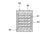
図2のIII-III断面図である。
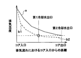
第1実施形態における排気流れにおけるコア入口からの距離と排気温度との関係を示す特性図である。
第2実施形態におけるEGRクーラを示す概略図である。
第2実施形態における排気流れにおけるコア入口からの距離と排気温度との関係を示す特性図である。
第3実施形態におけるEGRクーラを示す概略図である。
第4実施形態における排気熱交換システムの全体構成を示す概略図である。
以下、本開示の実施形態について図に基づいて説明する。なお、以下の各実施形態相互において、互いに同一もしくは均等である部分には、図中、同一符号を付してある。
(第1実施形態)
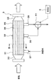
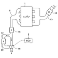
本開示の第1実施形態について図1~図4に基づいて説明する。図1に示すように、EGRシステムは、内燃機関としてのガソリンエンジン1の排気が流れる排気管(排気通路)11と、エアクリーナ12で濾過された吸入空気が流れている吸気管(吸気通路)13とに接続されたEGR管(EGR通路)2を備えている。このEGR通路2は、排気管11を流れる排気の一部を吸気管13に再循環させるためのものである。以下、ガソリンエンジン1はエンジン1と略す。
本開示の第1実施形態について図1~図4に基づいて説明する。図1に示すように、EGRシステムは、内燃機関としてのガソリンエンジン1の排気が流れる排気管(排気通路)11と、エアクリーナ12で濾過された吸入空気が流れている吸気管(吸気通路)13とに接続されたEGR管(EGR通路)2を備えている。このEGR通路2は、排気管11を流れる排気の一部を吸気管13に再循環させるためのものである。以下、ガソリンエンジン1はエンジン1と略す。
EGR通路2には、熱媒体としてのエンジンの冷却水とエンジン1の排気との間で熱交換を行うことで排気を冷却するEGRクーラ3が設けられている。本開示において、EGRクーラ3は熱交換器として機能させている。EGR通路2におけるEGRクーラ3の排気流れの下流部には、EGR通路2の通路開度を調整して、排気の循環量を制御するEGRバルブ4が設けられている。EGRバルブ4の作動は、後述するECU6から出力される制御信号によって制御される。
図2および図3に示すように、本実施形態のEGRクーラ3は、いずれも排気が流通する複数本のチューブ31を有するコア部32と、この複数本のチューブ31の長手方向両端部に配置されて排気の集合および分配を行う一対の分配集合用タンク33とを備えている。複数のチューブ31の内部には、冷却水とチューブ31との伝熱面積を増大させて冷却水と排気との熱交換を促進するインナーフィン34が設けられている。
インナーフィン34は、排気の流れ方向、すなわちチューブ31の長手方向に垂直な断面形状が矩形波状に形成されたストレートフィンである。
複数のチューブ31は、EGRクーラ3の外殻を形成する筒状のハウジング35により覆われている。つまり、複数のチューブ31は、ハウジング35の内部に配置されている。ハウジング35の長手方向両端部は、それぞれ、分配集合用タンク33に接合されている。これにより、分配集合用タンク33におけるコア部32に近い端面とハウジング35とによって、空間が形成される。この空間に冷却水を流通させることで、冷却水とチューブ31内の排気との間で熱交換を行い、排気を冷却することができる。以下、分配集合用タンク33におけるコア部32に近い端面とハウジング35とによって形成される空間を、冷却水流路36という。
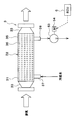
ハウジング35には、冷却水流路36に冷却水を流入させる冷却水入口37と、冷却水流路36から冷却水を流出させる第1冷却水出口38および第2冷却水出口39とが接続されている。冷却水入口37は、ハウジング35の排気流れの最上流部に接続されている。この最上流部は、排気が分配集合用タンク33からコア部32に流入する部位の近傍を示す。第2冷却水出口39は、第1冷却水出口38よりも排気流れの上流側に配置されている。本実施形態では、第1冷却水出口38は、ハウジング35の排気流れの最下流部に接続されている。この最下流部は、排気がコア部32から分配集合用タンク33に流出する部位の近傍を示す。これにより、冷却水入口37から冷却水流路36に流入した冷却水は、チューブ31内を流通する排気と熱交換し、第1冷却水出口38または第2冷却水出口39から流出する。
ここで、冷却水入口37をハウジング35の排気流れの最上流部に接続することで、コア部32に流入したばかりの高温の排気と、低温の冷却水とを熱交換させることができるので、冷却水が沸騰してしまうことを抑制できる。
第1冷却水出口38および第2冷却水出口39の冷却水流れの下流部には、電気式の三方弁51が接続されている。三方弁51は、冷却水入口37から冷却水流路36に流入した冷却水を第1冷却水出口38から流出させる第1冷却水回路と、冷却水入口37から冷却水流路36に流入した冷却水を第2冷却水出口39から流出させる第2冷却水回路とを切り替える冷却水回路切替装置である。この三方弁51は、後述するECU6から出力される制御信号によって、その作動が制御される。
本実施形態のEGRシステムには、各種制御を行う制御部としてのECU6が設けられている。ECU6は、各種入力信号に基づいて、EGRシステムを構成する各種制御機器の作動を制御するもので、CPU、ROM、RAM、I/O等を備えた周知のマイクロコンピュータによって構成され、ROM等の記憶部に記憶された制御プログラムに従って各種演算等の処理を実行する。
本実施形態では、ECU6には、冷却水の温度を検出する冷却水温度センサ(図示せず)からの検出信号等が入力される。そして、ECU6は、EGRバルブ4、三方弁51等が接続され、各種制御機器に制御信号を出力する。
具体的には、三方弁51は、冷却水の温度が予め定めた基準冷却水温度を上回ったときに第1冷却水回路に切り替え、冷却水の温度が基準冷却水温度以下になったときに第2冷却水回路に切り替える。これにより、冷却水温度が基準冷却水温度を上回ったときは、冷却水入口37から流入した冷却水は冷却水流路36の全域を循環し、第1冷却水出口38から流出する。この場合、図4中の実線"a"で示すように、コア部32の全域において、冷却水と排気との間で熱交換が行われて、排気が冷却される。
また、冷却水温度が基準冷却水温度以下になったときは、冷却水入口37から流入した冷却水は第2冷却水出口39から流出する。すなわち、冷却水は、冷却水流路36における冷却水入口37から第2冷却水出口39までの領域を循環する。この場合、図4中の破線"b1"で示すように、コア部32における冷却水入口37から第2冷却水出口39までの間において、冷却水と排気との間で熱交換が行われて、排気が冷却される。
一方、冷却水流路36における第2冷却水出口39と第1冷却水出口38との間の部分には冷却水が滞留し、冷却水流れに澱みが生じる。この場合、図4中の破線"b2"で示すように、コア部32における第2冷却水出口39と第1冷却水出口38との間では、冷却水温度が排気温度と近くなり、冷却水と排気との間で熱交換がほとんど行われなくなる。したがって、排気温度は、第2冷却水出口39部分における温度からほとんど下がることなく、コア部32の排気出口まで保持される。
本実施形態によれば、第1冷却水出口38を第2冷却水出口39よりも排気流れの下流側に配置するとともに、冷却水入口37から流入した冷却水を第1冷却水出口38から流出させる第1冷却水回路と、冷却水入口37から流入した冷却水を第2冷却水出口39から流出させる第2冷却水回路とを切り替える三方弁51を設けることで、三方弁51により、冷却水入口37から流入した冷却水を第2冷却水出口39から流出させる第2冷却水回路に切り替えた際に、EGRクーラ3における第2冷却水出口39の排気流れの下流領域、すなわち第2冷却水出口39と第1冷却水出口38との間には冷却水が循環しなくなる。
この場合、EGRクーラ3における第2冷却水出口39の排気流れの下流領域では、排気と冷却水との間で熱交換がほとんど行われなくなり、排気が冷却されなくなる。したがって、EGRクーラ3における第2冷却水出口39の排気流れの下流領域を通過する排気が低温になり過ぎることを抑制できるので、EGRクーラ3にPMが堆積することを抑制できる。
一方、三方弁51が第1冷却水回路および第2冷却水回路のいずれの冷却水回路に切り替えた場合であっても、EGRクーラ3における第2冷却水出口39よりも排気流れの上流側には冷却水が循環する。この場合、EGRクーラ3における第2冷却水出口39よりも排気流れの上流領域では、三方弁51の作動に関わらず、排気と冷却水との間で熱交換が行われて排気が冷却される。したがって、EGRクーラ3の冷却性能を確保しつつ、PMの付着によるEGRクーラの熱交換効率の低下および通風抵抗の増大を抑制できる。
また、本実施形態では、三方弁51を、冷却水の温度が基準冷却水温度を上回ったときに第1冷却水回路に切り替え、冷却水の温度が基準冷却水温度以下になったときに第2冷却水回路に切り替えるように構成している。この場合、冷却水の温度が低い場合に、EGRクーラ3における第2冷却水出口39の排気流れの下流領域で冷却水が循環しなくなり、EGRクーラ3における第2冷却水出口39の排気流れの下流領域では、排気と冷却水との間で熱交換がほとんど行われなくなる。したがって、冷却水温度が低い場合に、EGRクーラ3における第2冷却水出口39の排気流れの下流領域を通過する排気が低温になり過ぎることを抑制できるので、EGRクーラ3にPMが堆積することをより確実に抑制できる。
また、本実施形態は、三方弁51に限定していない。例えば、三方弁51のかわりに、第1冷却水出口38、第2冷却水出口39から流出する冷却水量の割合を変える流量調整弁を用いてもよい。
(第2実施形態)
次に、本開示の第2実施形態について図5および図6に基づいて説明する。本第2実施形態は、上記第1実施形態と比較して、EGRクーラ3の構造が異なるものである。前記第1実施例と同じ符号は、同一の構成を示すものであって、先行する説明を参照する。
次に、本開示の第2実施形態について図5および図6に基づいて説明する。本第2実施形態は、上記第1実施形態と比較して、EGRクーラ3の構造が異なるものである。前記第1実施例と同じ符号は、同一の構成を示すものであって、先行する説明を参照する。
図5に示すように、本実施形態のEGRクーラ3として、第1EGRクーラ3Aと、第2EGRクーラ3Bとが設けられている。第1EGRクーラ3Aは、第2EGRクーラ3Bよりも排気流れの上流側に配置されている。第1EGRクーラ3Aと第2EGRクーラ3Bとの間には、EGRバルブ4が配置されている。
第1EGRクーラ3Aは、第1実施形態と同様に、排気が流通する複数本の第1チューブ311を有する第1コア部321を備えている。また、第2EGRクーラ3Bは、第1実施形態と同様に、排気が流通する複数本の第2チューブ312を有する第2コア部322を備えている。第1チューブ311および第2チューブ312の内部には、それぞれ、第1実施形態と同様の形状のインナーフィン(図示せず)が配置されている。
第1チューブ311の排気流れの上流端部は、第1チューブ311に排気の分配を行う分配用タンク331に接続されている。また、第2チューブ312の排気流れの下流端部は、第2チューブ312から流出した排気を集合させる集合用タンク332に連通されている。また、第1チューブ311の排気流れの下流端部、および、第2チューブ312の排気流れの上流端部は、それぞれ、EGRバルブ4に接続されている。
したがって、EGRバルブ4の開弁時には、分配用タンク331に流入した排気は、第1EGRクーラ3Aの第1チューブ311に流入する。第1EGRクーラ3Aの第1チューブ311に流入した排気は、当該第1チューブ311内を流れて、EGRバルブ4へ流出する。そして、EGRバルブ4を通過した排気は、第2EGRクーラ3Bの第2チューブ312に流入する。第2EGRクーラ3Bの第2チューブ312に流入した排気は、当該第2チューブ312内を流れて集合用タンク332へ流出する。
ところで、複数の第1チューブ311は、第1EGRクーラ3Aの外殻を形成する筒状の第1ハウジング351により覆われている。同様に、複数の第2チューブ312は、第2EGRクーラ3Bの外殻を形成する筒状の第2ハウジング352により覆われている。
第1ハウジング351の長手方向一方の端部は、分配用タンク331に接合されている。第1ハウジング351の長手方向他方の端部は、EGRバルブ4に接合されている。これにより、分配用タンク331における第1コア部321に近い端面、EGRバルブ4における第1コア部321に近い端面、および第1ハウジング351によって、空間が形成される。この空間に冷却水を流通させることで、冷却水と第1チューブ311内の排気との間で熱交換を行い、排気を冷却することができる。以下、分配用タンク331における第1コア部321に近い端面、EGRバルブ4における第1コア部321に近い端面、および第1ハウジング351によって形成される空間を、第1冷却水流路361という。
第1ハウジング351には、第1冷却水流路361に冷却水を流入させる第1冷却水入口371と、第1冷却水流路361から冷却水を流出させる第1冷却水出口381とが接続されている。第1冷却水入口371は、第1ハウジング351の排気流れの最上流部に接続されている。この最上流部は、排気が分配用タンク331から第1コア部321に流入する部位の近傍を示す。第1冷却水出口381は、第1ハウジング351の排気流れの最下流部に接続されている。この最下流部は、排気が第1コア部321から流出する部位の近傍を示す。これにより、第1冷却水入口371から第1冷却水流路361に流入した冷却水は、第1チューブ311内を流通する排気と熱交換し、第1冷却水出口381から流出する。
第2ハウジング352の長手方向一方の端部は、集合用タンク332に接合されている。第2ハウジング352の長手方向他方の端部は、EGRバルブ4に接合されている。これにより、集合用タンク332における第2コア部322に近い端面、EGRバルブ4における第2コア部322に近い端面、および第2ハウジング352によって、空間が形成される。この空間に冷却水を流通させることで、冷却水と第2チューブ312内の排気との間で熱交換を行い、排気を冷却することができる。以下、集合用タンク332における第2コア部322に近い端面、EGRバルブ4における第2コア部322に近い端面、および第2ハウジング352によって形成される空間を、第2冷却水流路362という。
第2ハウジング352には、第2冷却水流路362に冷却水を流入させる第2冷却水入口372と、第2冷却水流路362から冷却水を流出させる第2冷却水出口382とが接続されている。第2冷却水入口372は、第2ハウジング352の排気流れの最上流部に接続されている。この最上流部は、排気が第2コア部322に流入する部位の近傍を示す。第2冷却水出口382は、第2ハウジング352の排気流れの最下流部に接続されている。この最下流部は、排気が第2コア部322から集合用タンク332へ流出する部位の近傍を示す。これにより、第2冷却水入口372から第2冷却水流路362に流入した冷却水は、第2チューブ312内を流通する排気と熱交換し、第2冷却水出口382から流出する。
第1冷却水出口381には、第1冷却水出口381から流出した冷却水が流通する第1出口通路391が接続されている。第2冷却水入口372には、第2冷却水入口372に流入した冷却水が流通する入口通路392が接続されている。
第1出口通路391には、温度によって体積変化するサーモワックス(感温部材)によって弁体を変位させて入口通路392を開閉する冷却水温度応動弁としてのサーモスタット52が設けられている。入口通路392は、サーモスタット52の第1出口52Aに接続されている。サーモスタット52の第2出口52Bは、第2出口通路393に接続されている。
サーモスタット52は、公知の技術であり、冷却水温度が所定温度より大きい場合は、入口通路392を開けて第2EGRクーラ3Bの第2冷却水流路362に冷却水が循環するようにし、逆に冷却水温度が所定温度以下の場合は、入口通路392を閉じて第2EGRクーラ3Bの第2冷却水流路362に冷却水が循環しないように制御することで温度制御を行っている。このとき、第1EGRクーラ3Aの第1冷却水流路361には、冷却水の温度に関わらず、冷却水が循環している。本例では、所定温度が90℃である。
すなわち、サーモスタット52は、第1EGRクーラ3Aおよび第2EGRクーラ3Bの双方に冷却水を流す第1冷却水回路と、第1EGRクーラ3Aのみに冷却水を流す第2冷却水回路とを切り替える冷却水回路切替装置の機能を果たしている。具体的には、サーモスタット52は、冷却水温度が基準冷却水温度より大きい場合は第1冷却水回路に切り替え、冷却水温度が基準冷却水温度以下の場合は第2冷却水回路に切り替える。
これにより、冷却水温度が基準冷却水温度を上回ったときは、入口通路392が開くので、第1冷却水入口371から流入した冷却水は第1EGRクーラ3Aの第1冷却水流路361を循環して第1冷却水出口381から流出する。さらに、第2冷却水入口372から流入した冷却水は第2EGRクーラ3Bの第2冷却水流路362を循環して第2冷却水出口382から流出する。この場合、図6中の実線"a"で示すように、第1EGRクーラ3Aにおいて冷却された排気が、第2EGRクーラ3Bにおいてさらに冷却される。
また、冷却水温度が基準冷却水温度以下になったときは、入口通路392が閉じるので、第1冷却水入口371から流入した冷却水は第1EGRクーラ3Aの第1冷却水流路361を循環して第1冷却水出口381から流出するが、第2EGRクーラ3Bの第2冷却水流路362には冷却水が循環しない。この場合、図6中の破線"b1"で示すように、第1EGRクーラ3Aにおいては排気が冷却されるが、第2EGRクーラ3Bの第2冷却水流路362では冷却水温度が排気温度と近くなり、図6中の破線"b2"で示すように、冷却水と排気との間で熱交換がほとんど行われなくなる。したがって、排気温度は、第1EGRクーラ3Aにおける第1コア部321の出口部分における温度からほとんど下がることなく、第2EGRクーラ3Bの第2コア部322の排気出口まで保持される。
本実施形態によれば、EGRクーラ3として、第1EGRクーラ3Aと、第1EGRクーラ3Aよりも排気の流れ方向における下流側に配置される第2EGRクーラ3Bとを設けることで、第1EGRクーラ3Aおよび第2EGRクーラ3Bのうち第1EGRクーラ3Aのみに冷却水を流すと、第2EGRクーラ3Bには熱媒体が循環しなくなる。この場合、第2EGRクーラ3Bでは、排気と熱媒体との間で熱交換がほとんど行われなくなり、排気が冷却されなくなる。したがって、第2EGRクーラ3Bを通過する排気が低温になることを抑制できるので、第2EGRクーラ3BにPMが堆積することを抑制できる。
このとき、第1EGRクーラ3Aには熱媒体が循環するので、排気と熱媒体との間で熱交換が行われて排気が冷却される。したがって、第1EGRクーラ3Aによって排気の冷却性能を確保しつつ、PMの付着による第2EGRクーラ3Bの熱交換効率の低下および通風抵抗の増大を抑制できる。
さらに、本実施形態では、冷却水の温度が基準冷却水温度を上回ったときに第1冷却水回路に切り替え、冷却水の温度が基準冷却水温度以下になったときに第2冷却水回路に切り替えるサーモスタット52を設けている。この場合、冷却水の温度が低い場合には、第2EGRクーラ3Bには冷却水が循環しなくなり、第2EGRクーラ3Bでは排気と冷却水との間で熱交換がほとんど行われなくなる。したがって、冷却水温度が低い場合に、第2EGRクーラ3Bを通過する排気が低温になり過ぎることを抑制できるので、第2EGRクーラ3BにPMが堆積することをより確実に抑制できる。
また、本実施形態は、サーモスタット52に限定していない。例えば、サーモスタット52のかわりに、第1冷却水出口381から第2出口通路393へと流出する冷却水量と第2冷却水入口372へ流入させる冷却水量の割合を変える流量調整弁を用いてもよい。
なお、排気温度が所定値を下回ると、凝縮水が発生する。この凝縮水による腐食を防止するためには、EGRクーラ3をステンレス等の耐食性の高い材料で構成する必要がある。本例では、所定値が54℃である。
本実施形態では、冷却水温度が低い場合に第2EGRクーラ3Bを通過する排気が低温になり過ぎることを抑制できるので、第2EGRクーラ3Bでは凝縮水が発生しなくなる。したがって、第2EGRクーラ3Bを、第1EGRクーラ3Aを構成する材料よりも耐食性が低い材料で構成することができる。
本例では、第1EGRクーラ3Aをステンレスで構成し、第2EGRクーラ3Bをアルミニウムで構成している。アルミニウムはステンレスよりも熱伝導性が優れているので、第2EGRクーラ3Bの冷却性能を向上させることができる。また、アルミニウムはステンレスよりも安価であるので、EGRクーラ3のコスト低減を図ることができる。
さらに、本実施形態では、EGRバルブ4を、第1EGRクーラ3Aと第2EGRクーラ3Bとの間に配置している。これにより、EGRバルブ4に、第2EGRクーラ3Bで冷却される前の排気を流入させることができるので、EGRバルブ4を通過する排気が低温になり過ぎることを抑制できる。したがって、EGRバルブ4にPMが堆積することを抑制できる。
(第3実施形態)
次に、本開示の第3実施形態について図7に基づいて説明する。本第3実施形態は、上記第1実施形態と比較して、EGRクーラ3の構造が異なるものである。前記第1実施例と同じ符号は、同一の構成を示すものであって、先行する説明を参照する。
次に、本開示の第3実施形態について図7に基づいて説明する。本第3実施形態は、上記第1実施形態と比較して、EGRクーラ3の構造が異なるものである。前記第1実施例と同じ符号は、同一の構成を示すものであって、先行する説明を参照する。
図7に示すように、本実施形態のEGRクーラ3のハウジング35には、冷却水流路36に冷却水を流入させる冷却水入口37と、冷却水流路36から冷却水を流出させる冷却水出口38が接続されている。冷却水入口37は、ハウジング35の排気流れの最上流部に接続されている。この最上流部は、排気が分配集合用タンク33からコア部32に流入する部位の近傍を示す。冷却水出口38は、ハウジング35の排気流れの最下流部に接続されている。この最下流部は、排気がコア部32から分配集合用タンク33へ流出する部位の近傍を示す。これにより、冷却水入口37から冷却水流路36に流入した冷却水は、チューブ31内を流通する排気と熱交換し、冷却水出口38から流出する。
冷却水出口38には、冷却水を圧送する冷却水循環ポンプ53の吸入口が接続されている。冷却水循環ポンプ53は、ポンプ用モータ54と機械的に接続されており、ポンプ用モータ54を回転させることにより冷却水循環ポンプ53を回転させて冷却水流路36に冷却水を循環させることができる。
冷却水循環ポンプ53の回転数を調整することで、冷却水流路36の冷却水流量を調整することができる。この場合、冷却水循環ポンプ53は、冷却水流路36を流通する冷却水の流量を調整する流量調整装置に相当している。ポンプ用モータ54は、ECU6から出力される制御信号によって制御される。具体的には、冷却水循環ポンプ53は、冷却水の温度が高い程、冷却水流路を流通する冷却水の流量を増加させる。
本実施形態によれば、冷却水の温度が高い程、冷却水流路36を流通する冷却水の流量を増加させる冷却水循環ポンプ53を設けることで、冷却水温度が低い場合には、冷却水流路36を流通する冷却水の流量が低下するので、EGRクーラ3において排気と冷却水との間で熱交換が行われ難くなる。したがって、冷却水温度が低い場合に、EGRクーラ3を通過する排気が低温になり過ぎることを抑制できるので、EGRクーラ3にPMが堆積することを抑制できる。
一方、冷却水温度が高い場合には、冷却水流路36を流通する冷却水の流量が増加するので、EGRクーラ3において排気と冷却水との間で熱交換が確実に行われ、排気が冷却される。したがって、EGRクーラ3の冷却性能を確保しつつ、PMの付着によるEGRクーラの熱交換効率の低下および通風抵抗の増大を抑制できる。
(第4実施形態)
次に、本開示の排気熱交換システムに関する第4実施形態について図8に基づいて説明する。前記実施例と同じ符号は、同一の構成を示すものであって、先行する説明を参照する。
次に、本開示の排気熱交換システムに関する第4実施形態について図8に基づいて説明する。前記実施例と同じ符号は、同一の構成を示すものであって、先行する説明を参照する。
図8に示すように、本実施形態の排気通路11に触媒15が設けられている。触媒15より排気通路11の排気流れの下流側に切替バルブ16が設けられている。本実施形態の排気熱交換システムは、触媒15と切替バルブ16との間を分岐し、切替バルブ16に接続された分岐通路17を備えている。分岐通路17に、排気と冷却水とを熱交換し、排気から冷却水へと熱量を回収する排熱回収器30が設けられている。
切替バルブ16は、触媒15から排出した排気が分岐通路17を通過させる第1排気回路の排気の流量と、触媒15から排出した排気が分岐通路17を通過させない第2排気回路の排気の流量との排気の流量割合を調整する切替装置である。具体的には、冷却水温度が所定温度より大きい場合は、分岐通路17を開けて冷却水と排気とを熱交換し、冷却水温度が所定温度以下の場合は、分岐通路17を閉じて冷却水と排気とを熱交換しないように制御する。あるいは、冷却水温度と排気の流量割合との関係を示すデータを予め算出し、このデータを用いて排気の流量割合を調整してもよい。
本第4実施形態では、排熱回収器30の具体的な構造としては上記第1実施形態から第3実施形態にわたって説明したEGRクーラ3と同様の構造を用いることができる。なお、排熱回収器30は熱交換器として機能させている。
本第4実施形態では、三方弁51と、サーモスタット52と、冷却水循環ポンプ53とは調整装置として機能させている。この調整装置は、第1冷却水回路の冷却水の流量と第2冷却水回路の冷却水の流量との冷却水の流量割合を調整する。具体的に、冷却水温度が所定温度より大きい場合は、分岐通路17を開けて冷却水と排気とを熱交換し、冷却水温度が所定温度以下の場合は、分岐通路17を閉じて冷却水と排気とを熱交換しないように制御する。あるいは、冷却水温度と冷却水の流量割合との関係を示すデータを予め算出し、このデータを用いて冷却水の流量割合を調整してもよい。
排気から回収された熱量は、例えば車室内の初期の暖房に用いられる。
(他の実施形態)
本開示は上述の実施形態に限定されることなく、本開示の趣旨を逸脱しない範囲内で、以下のように種々変形可能である。
本開示は上述の実施形態に限定されることなく、本開示の趣旨を逸脱しない範囲内で、以下のように種々変形可能である。
(1)上記第1実施形態では、三方弁51を、冷却水の温度に基づいて冷却水回路を切り替えるように構成した例について説明したが、これに限らず、三方弁51を、排気温度やエンジン1の負荷に基づいて冷却水回路を切り替えるように構成してもよい。なお、エンジン1の負荷は、エンジン回転数やギア位置等に基づいて決定される。
具体的には、三方弁51を、排気温度が予め定めた基準排気温度を上回ったときに第1冷却水回路に切り替え、排気温度が基準排気温度以下になったときに第2冷却水回路に切り替えるように構成してもよい。また、三方弁51を、エンジン1の負荷が予め定めた基準負荷を上回ったときに第1冷却水回路に切り替え、エンジン1の負荷が基準負荷以下になったときに第2冷却水回路に切り替えるように構成してもよい。
(2)上記第1実施形態では、第1冷却水回路と第2冷却水回路とを切り替える冷却水回路切替装置として、第1冷却水出口38および第2冷却水出口39の冷却水流れの下流部に接続した電気式の三方弁51を採用した例について説明したが、冷却水回路切替装置はこれに限定されない。
例えば、第1冷却水出口38および第2冷却水出口39のそれぞれに開閉弁を接続し、これらの開閉弁の開閉を制御することで、第1冷却水回路と第2冷却水回路とを切り替えてもよい。この場合、第1冷却水出口38に接続される開閉弁を開弁するとともに、第2冷却水出口39に接続される開閉弁を閉弁することで、第1冷却水回路に切り替えることができる。一方、第1冷却水出口38に接続される開閉弁を閉弁するとともに、第2冷却水出口39に接続される開閉弁を開弁することで、第2冷却水回路に切り替えることができる。
(3)上記第2実施形態では、第1冷却水回路と第2冷却水回路とを切り替える冷却水回路切替装置として、冷却水温度応動弁としてのサーモスタット52を採用した例について説明したが、これに限らず、ECU6から出力される制御信号によって、その開閉作動が制御される電磁開閉弁を採用してもよい。
この場合、冷却水温度、排気温度、エンジン1の負荷等に基づいて冷却水回路を切り替えるように、電磁開閉弁を制御してもよい。具体的には、冷却水温度が基準冷却水温度を上回ったときに第1冷却水回路に切り替え、冷却水温度が基準冷却水温度以下になったときに第2冷却水回路に切り替えるように、電磁開閉弁を制御してもよい。また、排気温度が予め定めた基準排気温度を上回ったときに第1冷却水回路に切り替え、排気温度が基準排気温度以下になったときに第2冷却水回路に切り替えるように、電磁開閉弁を制御してもよい。また、排気温度は、熱交換器に流入する排気入口温度と、熱交換器から流出する排気出口温度との少なくとも一つである。また、エンジン1の負荷が予め定めた基準負荷を上回ったときに第1冷却水回路に切り替え、エンジン1の負荷が基準負荷以下になったときに第2冷却水回路に切り替えるように、電磁開閉弁を制御してもよい。
(4)上記第4実施形態では、冷却水温度、排気温度、エンジン1の負荷等に基づいて排気回路を切り替えるように、切替バルブを制御してもよい。具体的には、冷却水温度が基準冷却水温度を上回ったときに第1排気回路に切り替え、冷却水温度が基準冷却水温度以下になったときに第2排気回路に切り替えるように、切替バルブを制御してもよい。また、冷却水温度と排気の流量割合との関係を示すデータを予め算出し、このデータを用いて切替バルブを制御してもよい。また、排気温度が予め定めた基準排気温度を上回ったときに第1排気回路に切り替え、排気温度が基準排気温度以下になったときに第2排気回路に切り替えるように、切替バルブを制御してもよい。また、排気温度と排気の流量割合との関係を示すデータを予め算出し、このデータを用いて切替バルブを制御してもよい。この場合、排気温度は、熱交換器に流入する排気入口温度と、熱交換器から流出する排気出口温度との少なくとも一つである。また、エンジン1の負荷が予め定めた基準負荷を上回ったときに第1排気回路に切り替え、エンジン1の負荷が基準負荷以下になったときに第2排気回路に切り替えるように、切替バルブを制御してもよい。また、エンジン1の負荷と排気の流量割合との関係を示すデータを予め算出し、このデータを用いて切替バルブを制御してもよい。
(5)上記実施形態では、冷却水に限らず、別の熱媒体を用いてもよい。
本開示は、実施例に準拠して記述されたが、本開示は当該実施例や構造に限定されるものではないと理解される。本開示は、様々な変形例や均等範囲内の変形をも包含する。加えて、様々な組み合わせや形態、さらには、それらに一要素のみ、それ以上、あるいはそれ以下、を含む他の組み合わせや形態をも、本開示の範疇や思想範囲に入るものである。
Claims (14)
- 内燃機関(1)の排気通路(11)と吸気通路(13)とを接続するEGR通路(2)に設けられるとともに、前記内燃機関(1)の排気と熱媒体との間で熱交換を行うことで前記排気を冷却するEGRクーラ(3)を備えるEGRシステムであって、
前記EGRクーラ(3)は、
前記熱媒体が流通する熱媒体流路(36)と、
前記熱媒体流路(36)に前記熱媒体を流入させる熱媒体入口(37)と、
前記熱媒体流路(36)から前記熱媒体を流出させる第1熱媒体出口(38)および第2熱媒体出口(39)とを有しており、
前記第1熱媒体出口(38)は、前記第2熱媒体出口(39)よりも前記排気の流れ方向の下流側に配置されており、
さらに、前記熱媒体入口(37)から流入した前記熱媒体を前記第1熱媒体出口(38)から流出させる第1熱媒体回路と、前記熱媒体入口(37)から流入した前記熱媒体を前記第2熱媒体出口(39)から流出させる第2熱媒体回路とを切り替える熱媒体回路切替装置(51)を備えることを特徴とするEGRシステム。 - 内燃機関(1)の排気通路(11)と吸気通路(13)とを接続するEGR通路(2)に設けられるとともに、前記内燃機関(1)の排気と熱媒体との間で熱交換を行うことで前記排気を冷却するEGRクーラ(3)と、
前記EGR通路(2)の通路開度を調整するEGRバルブ(4)とを備えるEGRシステムであって、
前記EGRクーラ(3)として、第1EGRクーラ(3A)と、前記第1EGRクーラ(3A)よりも前記排気の流れ方向における下流側に配置される第2EGRクーラ(3B)とが設けられており、
前記EGRバルブ(4)は、前記第1EGRクーラ(3A)と前記第2EGRクーラ(3B)との間に設けられていることを特徴とするEGRシステム。 - さらに、前記第1EGRクーラ(3A)および前記第2EGRクーラ(3B)の双方に前記熱媒体を流す第1熱媒体回路と、前記第1EGRクーラ(3A)および前記第2EGRクーラ(3B)のうち前記第1EGRクーラ(3A)のみに前記熱媒体を流す第2熱媒体回路とを切り替える熱媒体回路切替装置(52)を備えることを特徴とする請求項2に記載のEGRシステム。
- 前記熱媒体回路切替装置(51、52)は、前記熱媒体の温度が予め定めた基準熱媒体温度を上回ったときに前記第1熱媒体回路に切り替え、前記熱媒体の温度が前記基準熱媒体温度以下になったときに前記第2熱媒体回路に切り替えることを特徴とする請求項1または3に記載のEGRシステム。
- 前記熱媒体回路切替装置(51、52)は、前記排気の温度が予め定めた基準排気温度を上回ったときに前記第1熱媒体回路に切り替え、前記排気の温度が前記基準排気温度以下になったときに前記第2熱媒体回路に切り替えることを特徴とする請求項1または3に記載のEGRシステム。
- 前記排気の温度が、前記EGRクーラ(3、3A、3B)に流入する排気入口温度と、前記EGRクーラ(3、3A、3B)から流出する排気出口温度との少なくとも一つであることを特徴とする請求項5に記載のEGRシステム。
- 前記熱媒体回路切替装置(51、52)は、前記内燃機関(1)の負荷が予め定めた基準負荷を上回ったときに前記第1熱媒体回路に切り替え、前記内燃機関(1)の負荷が前記基準負荷以下になったときに前記第2熱媒体回路に切り替えることを特徴とする請求項1または3に記載のEGRシステム。
- 内燃機関(1)の排気通路(11)と吸気通路(13)とを接続するEGR通路(2)に設けられるとともに、前記内燃機関(1)の排気と熱媒体との間で熱交換を行うことで前記排気を冷却するEGRクーラ(3)を備えるEGRシステムであって、
前記EGRクーラ(3)は、前記熱媒体が流通する熱媒体流路(36)を有しており、
さらに、前記熱媒体流路(36)を流通する前記熱媒体の流量を調整する流量調整装置(53)を備え、
前記流量調整装置(53)は、前記熱媒体の温度が高い程、前記熱媒体流路(36)を流通する前記熱媒体の流量を増加させることを特徴とするEGRシステム。 - 内燃機関(1)の排気と熱媒体との間で熱交換を行う熱交換器(3、30)を備える排気熱交換システムであって、
前記熱交換器(3、30)は、
前記熱媒体が流通する熱媒体流路(36)と、
前記熱媒体流路(36)に前記熱媒体を流入させる熱媒体入口(37)と、
前記熱媒体流路(36)から前記熱媒体を流出させる第1熱媒体出口(38)および第2熱媒体出口(39)とを有しており、
前記第1熱媒体出口(38)は、前記第2熱媒体出口(39)よりも前記排気の流れ方向の下流側に配置されており、
さらに、前記熱媒体入口(37)から流入した前記熱媒体を前記第1熱媒体出口(38)から流出させる第1熱媒体回路の熱媒体の流量と、前記熱媒体入口(37)から流入した前記熱媒体を前記第2熱媒体出口(39)から流出させる第2熱媒体回路の熱媒体の流量との流量割合を調整する調整装置(51、52,53)を備えることを特徴とする排気熱交換システム。 - 前記調整装置(51、52,53)は、前記熱媒体の温度が予め定めた基準熱媒体温度を上回ったときに前記第1熱媒体回路に切り替え、前記熱媒体の温度が前記基準熱媒体温度以下になったときに前記第2熱媒体回路に切り替えることを特徴とする請求項9に記載の排気熱交換システム。
- 前記調整装置(51、52,53)は、前記排気の温度が予め定めた基準排気温度を上回ったときに前記第1熱媒体回路に切り替え、前記排気の温度が前記基準排気温度以下になったときに前記第2熱媒体回路に切り替えることを特徴とする請求項9に記載の排気熱交換システム。
- 前記排気の温度が、前記熱交換器(3、30)に流入する排気入口温度と、前記熱交換器(3、30)から流出する排気出口温度との少なくとも一つであることを特徴とする請求項11に記載の排気熱交換システム。
- 前記調整装置(51、52,53)は、前記内燃機関(1)の負荷が予め定めた基準負荷を上回ったときに前記第1熱媒体回路に切り替え、前記内燃機関(1)の負荷が前記基準負荷以下になったときに前記第2熱媒体回路に切り替えることを特徴とする請求項9に記載の排気熱交換システム。
- 前記熱交換器(3)は、内燃機関(1)の吸気通路(13)に接続されるEGR通路(2)に設けられ、前記排気を冷却するEGRクーラであることを特徴とする請求項9から13のいずれかに記載の排気熱交換システム。
Applications Claiming Priority (2)
| Application Number | Priority Date | Filing Date | Title |
|---|---|---|---|
| JP2012-162824 | 2012-07-23 | ||
| JP2012162824A JP2014020345A (ja) | 2012-07-23 | 2012-07-23 | Egrシステム |
Publications (1)
| Publication Number | Publication Date |
|---|---|
| WO2014017014A1 true WO2014017014A1 (ja) | 2014-01-30 |
Family
ID=49996842
Family Applications (1)
| Application Number | Title | Priority Date | Filing Date |
|---|---|---|---|
| PCT/JP2013/003853 Ceased WO2014017014A1 (ja) | 2012-07-23 | 2013-06-20 | Egrシステムおよび排気熱交換システム |
Country Status (2)
| Country | Link |
|---|---|
| JP (1) | JP2014020345A (ja) |
| WO (1) | WO2014017014A1 (ja) |
Cited By (2)
| Publication number | Priority date | Publication date | Assignee | Title |
|---|---|---|---|---|
| CN110579120A (zh) * | 2019-08-30 | 2019-12-17 | 安徽池州九华发电有限公司 | 管壳式换热器及其控制方法 |
| CN116517668A (zh) * | 2022-01-24 | 2023-08-01 | 比亚迪股份有限公司 | 发动机余热回收系统和具有其的车辆 |
Families Citing this family (5)
| Publication number | Priority date | Publication date | Assignee | Title |
|---|---|---|---|---|
| US9528475B2 (en) * | 2014-11-11 | 2016-12-27 | Ford Global Technologies, Llc | Method and system for EGR control |
| CN105443274B (zh) * | 2015-12-07 | 2018-03-13 | 潍柴动力股份有限公司 | 多级冷却egr冷却系统 |
| JP7075220B2 (ja) * | 2018-01-19 | 2022-05-25 | 株式会社Subaru | 排気クーラ |
| KR20200028111A (ko) * | 2018-09-06 | 2020-03-16 | 현대자동차주식회사 | 이지알 쿨러 |
| DE102018217757A1 (de) * | 2018-10-17 | 2020-04-23 | Volkswagen Aktiengesellschaft | Abgasrückführungskühler und Verfahren zur Kühlungvon Abgas einer Brennkraftmaschine mit einer Kühlflüssigkeit |
Citations (8)
| Publication number | Priority date | Publication date | Assignee | Title |
|---|---|---|---|---|
| JP2001140701A (ja) * | 1999-11-15 | 2001-05-22 | Nissan Motor Co Ltd | エンジンのegr装置 |
| JP2001140704A (ja) * | 1999-10-07 | 2001-05-22 | Cummins Engine Co Inc | 内燃機関用の冷却排気ガス再循環用の高温冷却剤ループ |
| JP2005220747A (ja) * | 2004-02-03 | 2005-08-18 | Usui Kokusai Sangyo Kaisha Ltd | Egrガス冷却機構 |
| JP2008500489A (ja) * | 2004-05-28 | 2008-01-10 | スカニア シーブイ アクチボラグ(パブル) | 過給気内燃機関の排気再循環装置 |
| JP2009537743A (ja) * | 2006-05-19 | 2009-10-29 | マーレ インターナショナル ゲゼルシャフト ミット ベシュレンクテル ハフツング | 排ガス再循環装置 |
| JP2011106289A (ja) * | 2009-11-12 | 2011-06-02 | Toyota Industries Corp | Egrガス冷却装置 |
| JP2011190742A (ja) * | 2010-03-15 | 2011-09-29 | Denso Corp | 内燃機関用排気再循環装置 |
| WO2012086181A1 (ja) * | 2010-12-22 | 2012-06-28 | 株式会社デンソー | 排気熱交換装置 |
-
2012
- 2012-07-23 JP JP2012162824A patent/JP2014020345A/ja active Pending
-
2013
- 2013-06-20 WO PCT/JP2013/003853 patent/WO2014017014A1/ja not_active Ceased
Patent Citations (8)
| Publication number | Priority date | Publication date | Assignee | Title |
|---|---|---|---|---|
| JP2001140704A (ja) * | 1999-10-07 | 2001-05-22 | Cummins Engine Co Inc | 内燃機関用の冷却排気ガス再循環用の高温冷却剤ループ |
| JP2001140701A (ja) * | 1999-11-15 | 2001-05-22 | Nissan Motor Co Ltd | エンジンのegr装置 |
| JP2005220747A (ja) * | 2004-02-03 | 2005-08-18 | Usui Kokusai Sangyo Kaisha Ltd | Egrガス冷却機構 |
| JP2008500489A (ja) * | 2004-05-28 | 2008-01-10 | スカニア シーブイ アクチボラグ(パブル) | 過給気内燃機関の排気再循環装置 |
| JP2009537743A (ja) * | 2006-05-19 | 2009-10-29 | マーレ インターナショナル ゲゼルシャフト ミット ベシュレンクテル ハフツング | 排ガス再循環装置 |
| JP2011106289A (ja) * | 2009-11-12 | 2011-06-02 | Toyota Industries Corp | Egrガス冷却装置 |
| JP2011190742A (ja) * | 2010-03-15 | 2011-09-29 | Denso Corp | 内燃機関用排気再循環装置 |
| WO2012086181A1 (ja) * | 2010-12-22 | 2012-06-28 | 株式会社デンソー | 排気熱交換装置 |
Cited By (3)
| Publication number | Priority date | Publication date | Assignee | Title |
|---|---|---|---|---|
| CN110579120A (zh) * | 2019-08-30 | 2019-12-17 | 安徽池州九华发电有限公司 | 管壳式换热器及其控制方法 |
| CN110579120B (zh) * | 2019-08-30 | 2020-11-24 | 安徽池州九华发电有限公司 | 管壳式换热器及其控制方法 |
| CN116517668A (zh) * | 2022-01-24 | 2023-08-01 | 比亚迪股份有限公司 | 发动机余热回收系统和具有其的车辆 |
Also Published As
| Publication number | Publication date |
|---|---|
| JP2014020345A (ja) | 2014-02-03 |
Similar Documents
| Publication | Publication Date | Title |
|---|---|---|
| WO2014017014A1 (ja) | Egrシステムおよび排気熱交換システム | |
| US8333068B2 (en) | Exhaust heat recovery device | |
| US9238994B2 (en) | Cooling device for a hybrid vehicle | |
| JP5582022B2 (ja) | 排気熱交換装置 | |
| JP4432979B2 (ja) | 排気熱回収システム | |
| CN102356217B (zh) | 用于注油转动或摆动部件的方法和设备 | |
| CN108699945B (zh) | 车辆用内燃机的冷却装置及控制方法 | |
| CN105874182B (zh) | 进气冷却装置 | |
| US20180038267A1 (en) | Cooling Device of Internal Combustion Engine for Vehicle and Control Method Thereof | |
| JP5825184B2 (ja) | エンジン冷却装置 | |
| JP6011495B2 (ja) | 冷却水制御装置 | |
| US10358970B2 (en) | Cooling assembly for temperature control | |
| US11125190B2 (en) | Methods and system for an engine system | |
| JP2013087761A (ja) | エンジン冷却水循環システム | |
| JP5321419B2 (ja) | Egrガス冷却装置 | |
| JP6094231B2 (ja) | 内燃機関の冷却システム | |
| CN110259561B (zh) | 一种车辆油温热管理系统及车辆 | |
| CN107448330B (zh) | 用于机动车辆的内燃机的多功能模块 | |
| US8671669B2 (en) | Exhaust gas cooler for a motor vehicle | |
| JP6131937B2 (ja) | ロータリピストンエンジンの冷却装置 | |
| JP4998390B2 (ja) | 冷却水循環装置 | |
| JP6256578B2 (ja) | 内燃機関の冷却システム | |
| JP5907275B2 (ja) | 内燃機関の冷却装置 | |
| JP2024119536A (ja) | 排熱回収制御システム | |
| JP2017223168A (ja) | 冷却装置 |
Legal Events
| Date | Code | Title | Description |
|---|---|---|---|
| 121 | Ep: the epo has been informed by wipo that ep was designated in this application |
Ref document number: 13822432 Country of ref document: EP Kind code of ref document: A1 |
|
| NENP | Non-entry into the national phase |
Ref country code: DE |
|
| 122 | Ep: pct application non-entry in european phase |
Ref document number: 13822432 Country of ref document: EP Kind code of ref document: A1 |