WO2014013583A1 - 医療用デバイス - Google Patents
医療用デバイス Download PDFInfo
- Publication number
- WO2014013583A1 WO2014013583A1 PCT/JP2012/068294 JP2012068294W WO2014013583A1 WO 2014013583 A1 WO2014013583 A1 WO 2014013583A1 JP 2012068294 W JP2012068294 W JP 2012068294W WO 2014013583 A1 WO2014013583 A1 WO 2014013583A1
- Authority
- WO
- WIPO (PCT)
- Prior art keywords
- flow path
- medical device
- distal end
- medical instrument
- insertion portion
- Prior art date
- Legal status (The legal status is an assumption and is not a legal conclusion. Google has not performed a legal analysis and makes no representation as to the accuracy of the status listed.)
- Ceased
Links
Images



Classifications
-
- A—HUMAN NECESSITIES
- A61—MEDICAL OR VETERINARY SCIENCE; HYGIENE
- A61B—DIAGNOSIS; SURGERY; IDENTIFICATION
- A61B1/00—Instruments for performing medical examinations of the interior of cavities or tubes of the body by visual or photographical inspection, e.g. endoscopes; Illuminating arrangements therefor
- A61B1/00147—Holding or positioning arrangements
- A61B1/00154—Holding or positioning arrangements using guiding arrangements for insertion
-
- A—HUMAN NECESSITIES
- A61—MEDICAL OR VETERINARY SCIENCE; HYGIENE
- A61B—DIAGNOSIS; SURGERY; IDENTIFICATION
- A61B1/00—Instruments for performing medical examinations of the interior of cavities or tubes of the body by visual or photographical inspection, e.g. endoscopes; Illuminating arrangements therefor
- A61B1/12—Instruments for performing medical examinations of the interior of cavities or tubes of the body by visual or photographical inspection, e.g. endoscopes; Illuminating arrangements therefor with cooling or rinsing arrangements
- A61B1/126—Instruments for performing medical examinations of the interior of cavities or tubes of the body by visual or photographical inspection, e.g. endoscopes; Illuminating arrangements therefor with cooling or rinsing arrangements provided with means for cleaning in-use
-
- A—HUMAN NECESSITIES
- A61—MEDICAL OR VETERINARY SCIENCE; HYGIENE
- A61B—DIAGNOSIS; SURGERY; IDENTIFICATION
- A61B1/00—Instruments for performing medical examinations of the interior of cavities or tubes of the body by visual or photographical inspection, e.g. endoscopes; Illuminating arrangements therefor
- A61B1/233—Instruments for performing medical examinations of the interior of cavities or tubes of the body by visual or photographical inspection, e.g. endoscopes; Illuminating arrangements therefor for the nose, i.e. nasoscopes, e.g. testing of patency of Eustachian tubes
-
- A—HUMAN NECESSITIES
- A61—MEDICAL OR VETERINARY SCIENCE; HYGIENE
- A61M—DEVICES FOR INTRODUCING MEDIA INTO, OR ONTO, THE BODY; DEVICES FOR TRANSDUCING BODY MEDIA OR FOR TAKING MEDIA FROM THE BODY; DEVICES FOR PRODUCING OR ENDING SLEEP OR STUPOR
- A61M25/00—Catheters; Hollow probes
- A61M25/0067—Catheters; Hollow probes characterised by the distal end, e.g. tips
-
- A—HUMAN NECESSITIES
- A61—MEDICAL OR VETERINARY SCIENCE; HYGIENE
- A61M—DEVICES FOR INTRODUCING MEDIA INTO, OR ONTO, THE BODY; DEVICES FOR TRANSDUCING BODY MEDIA OR FOR TAKING MEDIA FROM THE BODY; DEVICES FOR PRODUCING OR ENDING SLEEP OR STUPOR
- A61M29/00—Dilators with or without means for introducing media, e.g. remedies
-
- A—HUMAN NECESSITIES
- A61—MEDICAL OR VETERINARY SCIENCE; HYGIENE
- A61M—DEVICES FOR INTRODUCING MEDIA INTO, OR ONTO, THE BODY; DEVICES FOR TRANSDUCING BODY MEDIA OR FOR TAKING MEDIA FROM THE BODY; DEVICES FOR PRODUCING OR ENDING SLEEP OR STUPOR
- A61M25/00—Catheters; Hollow probes
- A61M2025/0019—Cleaning catheters or the like, e.g. for reuse of the device, for avoiding replacement
Definitions
- the present invention relates to a medical device for supporting insertion of a medical instrument into a living body and cleaning the medical instrument.
- Patent Document 1 discloses a so-called sonde in which a probe distal end portion of a medical treatment instrument is formed in a spatula shape as a medical treatment instrument used in an intranasal treatment together with an endoscope.
- a medical treatment instrument having a spatula shape such as a sonde described in Patent Document 1
- a narrow site in the nasal cavity can be pushed and guided to the diagnostic site.
- a medical treatment instrument having a spatula shape as in Patent Document 1 does not have a cleaning function for a medical instrument such as an endoscope. Therefore, even if a medical treatment instrument such as Patent Document 1 is used, when a bodily fluid such as a runny nose adheres to the medical instrument, the medical instrument is once removed from the living body, wiped with gauze, and then again in the living body. Need to be inserted into. Body fluids such as runny nose are present in many parts of the living body, and there is a problem that if the medical instrument is taken out from the living body every time the body fluid adheres to the medical instrument, the procedure becomes complicated.
- An object of the present invention is to provide a medical device capable of removing deposits.
- a medical device that achieves the above-described object is provided from an elongate main body portion, a distal end portion that is provided on the distal end side of the main body portion and has a flat surface portion that extends in the surface direction, and a proximal end side of the main body portion.
- a flow path that can flow through the distal end portion and a fluid that extends to the proximal end side of the main body portion via the distal end portion, and a portion that is provided at the distal end portion and that is to be cleaned of a medical device faces the flow path
- An insertion portion that can be inserted into the insertion portion, and a guide portion that guides insertion of the medical instrument into the insertion portion.
- the medical device includes a distal end portion having a flat surface portion, and can perform operations such as pushing and spreading the distal end portion against a narrow portion where it is difficult to insert the medical instrument. Smooth insertion can be supported.
- the medical device has a flow path through which a fluid can flow, and an insertion portion into which a medical instrument can be inserted is provided at the distal end portion of the medical device in the flow path.
- the medical device also has a guide portion for guiding insertion of the medical instrument into the insertion portion. For this reason, the site to be cleaned of the medical device can be smoothly inserted into the insertion portion using the guide portion, and the adhering matter attached to the medical device can be removed without removing the medical device from the living body.
- FIG. 4 is a cross-sectional view taken along line 4-4 of FIG. It is an enlarged view which shows the front-end
- 6A and 6B are enlarged views showing the distal end portion of the medical device according to the modification of the present invention. It is an enlarged view which shows the front-end
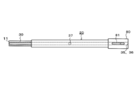
- FIG. 1 is a front view showing a medical device according to an embodiment of the present invention
- FIG. 2 is a plan view showing the medical device
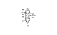
- FIG. 3 is a left side view showing the medical device
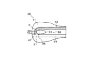
- FIG. 5 is an enlarged view showing a distal end portion of the medical device.
- the medical device 100 is provided with an elongated main body 20 and a flat surface 11 that is provided on the distal end side of the main body 20 and extends in the surface direction. And a flow path 30 capable of flowing a fluid extending from the base end side of the main body portion 20 to the front end portion 10 and extending to the base end side of the main body portion 20 via the front end portion 10.
- the medical device 100 is provided at the distal end portion 10 and can be inserted so that a portion to be cleaned of the medical device faces the flow path 30.
- the medical device 100 is inserted into the insertion portion 50.
- the guide part 60 which guides.
- a water tank 200 is connected as a water source to the upstream side of the flow path 30, and a negative pressure generating means 300 such as a pump is connected to the downstream side.
- the distal end portion 10 is provided with an opening 40 that opens to the distal end surface of the distal end portion 10 and communicates with the flow path 30.
- bodily fluids such as runny nose that can adhere to the medical device are sucked from the opening 40.
- the flow path 30 is curved in the vicinity of the insertion portion 50 in the distal end portion 10, and the outer shape 33 of the flow path 30 on the upstream side of the insertion portion 50 and the flow path 30 on the downstream side of the insertion portion 50.
- An outer shape 34 is formed in communication with the U shape.
- the flow path 30 is provided with a merging portion 31 that merges with a pipe 41 extending from the opening 40.
- a guide through-hole 61 for a medical instrument penetrating in the thickness direction of the planar portion is provided on the proximal end side with respect to the insertion portion 50.
- a light source 70 that facilitates visual recognition of the insertion portion 50 is provided inside the flow path.
- a hub 80 is provided on the proximal end side as a connection portion to the medical device 100. Details will be described below.
- the hub 80 is a connection part between the medical device 100 and an external device, and has blades 81 and 82. At the time of connection, the blades 81 and 82 can be easily pinched.
- the distal end portion 10 has a flat surface portion 11 so that a narrow portion existing on the insertion path of the medical instrument can be pushed and spread in order to deliver a medical instrument such as an endoscope to the diagnosis site.
- the flat surface portion 11 is configured such that the width of the tip portion of the flat surface portion 11 protrudes outward from the outer surface of the tubular body of the main body portion 20 so that a narrow portion in the living body can be pushed and spread.
- the width of the tip portion of the flat portion 11 is formed to be relatively large, so that a sufficient contact area between the narrow portion in the living body and the flat portion 11 can be secured.
- the part can be expanded.
- the plane part 11 is formed so that the center axis
- the main body 20 is a tubular body formed from the tip of the hub 80 to the tip 10. A path for fluid flowing through the flow path 30 is formed in the main body 20.
- a fluid such as water flows through the flow path 30 in order to remove deposits adhering to a site to be cleaned such as a lens portion of a medical instrument such as an endoscope, and collects bodily fluid such as a runny nose sucked from the opening 40.
- the flow path 30 includes a flow path entrance 35 for flowing fluid to the proximal end side, a flow path outlet 36 for discharging the fluid flowing through the flow path 30, and an open hole for controlling the inflow of fluid from the flow path entrance 35. 37 and an inner wall 38 provided in the vicinity of the insertion portion 50 on the path of the flow path 30.
- the flow path entrance 35 is connected to a water tank 200 containing a fluid such as water as shown in FIG.
- a fluid having a cleaning ability such as water flows from the flow path inlet 35 and flows to the flow path outlet 36 via a U-shaped curved tip portion.
- the flow path outlet 36 is connected to a negative pressure generating means 300 such as a pump via a valve 301 as shown in FIG. Due to the suction force of the negative pressure generating means 300, fluid from the upstream of the flow path 30 and bodily fluids such as runny nose from the opening 40 flow to the fluid outlet 36.
- the open hole 37 is a part where the internal space of the flow channel 30 communicates with the outside other than the flow channel inlet 35 and the flow channel outlet 36.
- the negative pressure generating means 300 When the negative pressure generating means 300 is always operated, if the open hole 37 communicates with the outside, air is sucked from the open hole 37, so that no negative pressure is applied to the opening 40 and suction is performed from the opening 40. Is not done. Suction is performed from the opening 40 by closing the part of the open hole 37 with a finger or the like so that the internal space of the part of the open hole 37 is secured. In this case, the negative pressure is applied to the opening 40 through the flow path 30 and also applied to the flow path entrance 35 side.
- a channel narrowed by an inner wall 38 and an insertion portion 50 are provided on the channel inlet 35 side. For this reason, normally, when the suction action is performed by closing the open hole 37, the object to be sucked from the opening 40, the air flowing in from the insertion portion 50 from the side of the flow path inlet 35 is mixed, and the sucked object is drawn in while entraining the air. Therefore, efficient suction can be performed. Further, when the object to be cleaned is inserted into the insertion portion 50 with the open hole 37 being blocked, the opening of the insertion portion 50 is blocked, so that a negative pressure is applied to the channel inlet 35 through the channel 30, and from the water tank 200. Liquid flows in.
- the inflowing liquid is sucked and collected from the flow path outlet 36 while washing the object to be cleaned inserted into the insertion portion 50. Accordingly, when it is desired to clean the object to be cleaned, the liquid starts to flow automatically and is simply washed by being inserted into the insertion portion 50, so that the washing operation can be performed more simply.
- the inner wall 38 is a wall inside the channel provided in the vicinity of the insertion portion 50 in the channel 30 as shown in FIG.
- the cross-sectional area of the portion where the inner wall 38 is provided in the path of the flow path 30 is reduced.
- the flow velocity at the portion where the cross-sectional area is reduced is increased, and the suction force of fluid such as water can be enhanced correspondingly, and the cleaning power can be further increased.
- the opening 40 has the shape of the tip portion of the medical device 100 among the pipes 41 that merge with the flow path 30.
- the opening 40 is provided for aspirating in-vivo bodily fluids or the like that can adhere to a medical instrument that exists on a path until a medical instrument such as an endoscope is delivered to a diagnostic site.
- the opening 40 and the pipe line 41 have substantially the same shape as the cross-sectional shape of the flow path 30 in this embodiment.
- the inner surface of the pipe 41 is formed so as to be continuously connected to the shape of the inner surface in the vicinity of the merge portion 31 in the flow channel 30.
- body fluid such as nasal mucus can be sucked without depositing body fluid or the like from the opening 40 in the junction 31 with the flow path 30.
- the merge part 31 is a part where the pipe line 41 merges with the flow path 30.
- the merging portion 31 includes a tangential direction in which a fluid flows at a merging portion with the pipe 41 of the flow path 30 and a flow path of the pipe 41 so that the flow from the opening 40 and the flow from the flow path 30 do not face each other.
- 30 may be formed so that an angle formed by a tangential direction in which the fluid flows is an acute angle.
- the insertion portion 50 is formed as an insertion through hole 51 for inserting a medical instrument on the side surface of the distal end portion 10.
- the insertion through hole 51 is provided in the vicinity of the distal end portion 10 of the medical device 100 in the flow path 30.
- the insertion through hole 51 is formed so as to face the base end side in this embodiment. Therefore, a medical instrument such as an endoscope inserted from the base end side can be smoothly inserted into the medical device 100, and a site to be cleaned such as a lens portion can be quickly cleaned.
- the guide part 60 includes the outer shapes 33 and 34 of the flow path 30 bulged from the flat part of the tip part 10 at the tip part 10. Further, as shown in FIG. 1, the outer shapes 33 and 34 of the flow path 30 are such that the distance between the outer shape 33 and the outer shape 34 approaches from the proximal end side to the distal end side at an arbitrary position in the longitudinal direction of the main body 20. It is comprised so that it may become small as it goes.
- the guide portion 60 includes a guide through hole 61 penetrating in the thickness direction of the flat surface portion 11 formed on the base end side with respect to the insertion through hole 51 of the insertion portion 50.
- the guide through-hole 61 is formed so as to penetrate in the thickness direction of the flat surface portion 11, a medical instrument such as an endoscope can be inserted into the insertion portion 50 through the through-hole even when entering from any flat surface side. Since it can be cleaned regardless of the user's dominant hand or the orientation of the device at the time of use, the medical instrument can be more easily cleaned.
- the guide portion 60 may include at least one of a shape in which the edge portion of the insertion through hole 51 as the insertion portion 50 is convex and a shape in which the edge is concave.
- the light source 70 is disposed inside the flow path 30 and is disposed in the vicinity of the insertion through hole 51 in the distal end portion of the medical device 100 in the flow path 30.
- the light source 70 is constituted by a long optical fiber as shown in FIG. 5, for example, but is not limited to this as long as it emits a light amount above a certain level.
- the light source 70 is arranged so that its tip extends to the duct 41 so as to face the opening 40, or is arranged on the outer surface of the tip so as to illuminate the site of the sinus that is the target of the procedure. May be.
- the endoscope E is inserted into the nasal cavity and advanced.
- the medical device 100 is used to push the middle turbinate portion apart and insert the endoscope E further into the back side.
- the negative pressure generating means 300 is operated, and the bodily fluid such as runny nose is sucked into the endoscope E from the opening 40 with the open hole 37 closed. To prevent adhesion.
- body fluid such as a runny nose adheres to the lens portion of the endoscope E, the endoscope E is inserted into the insertion portion 50.
- the principle of cleaning the lens part of the endoscope E is as follows.
- a fluid such as water can flow from the flow path inlet 35, and air can be sucked from the insertion portion 50.
- the endoscope E is not inserted into the insertion portion 50 due to the difference in the viscosity due to the difference in the viscosity of air and water and the difference in the path length, the insertion through-hole is formed from the flow path 30 upstream of the joining portion 31. Air from 51 flows and flows to the flow path outlet 36 together with the body fluid sucked from the opening 40.
- a spatula-like part such as a sonde is inserted into the sinuses together with an endoscope, and a narrow part is also expanded in the paranasal sinuses such as the middle turbinates to further enter the living body.
- the spatula part does not have a cleaning function. Therefore, when a body fluid or the like adheres to the lens portion, it is necessary to remove the endoscope from the living body, wipe it off with gauze, and then introduce it again into the living body, which makes the procedure complicated.
- the flow path 30 provided with an insertion through hole 51 for inserting an endoscope into the distal end portion 10.
- a guide portion 60 for guiding insertion of the endoscope into the insertion through hole 51 is provided. Therefore, a medical instrument such as an endoscope can be smoothly inserted into the insertion through hole 51 and cleaned without being taken out from the living body.
- the medical device 100 includes the distal end portion 10 having the flat surface portion 11, so that the distal end portion 10 is applied to a narrow portion where insertion of a medical instrument is difficult, and spreads.
- smooth insertion of the medical device can be supported.
- the medical device 100 has a flow path 30 through which fluid can be circulated, and an insertion portion 50 in which a medical instrument can be inserted is provided in the vicinity of the distal end portion of the medical device 100 in the flow path 30. . Furthermore, the medical device 100 also has a guide part 60 for guiding insertion of the medical instrument into the insertion part 50.
- the site to be cleaned of the medical device can be smoothly inserted up to the insertion portion 50 using the guide unit 60, and the deposits attached to the medical device can be removed without removing the medical device from the living body.
- the distal end portion 10 has an opening portion 40 that opens to the distal end surface of the distal end portion 10 and communicates with the flow path 30. Therefore, by connecting the negative pressure generating means 300 to the flow path 30 and performing suction, body fluid such as a nasal mucus present on a path through which a medical instrument such as an endoscope enters the living body can be sucked and removed as needed. It is possible to make it difficult for body fluid to adhere to the medical device.
- the flow path 30 has a merging portion 31 that merges with a pipe line 41 extending from the opening 40 at the distal end portion 10, and the insertion part 50 is provided upstream of a position where the flow path 30 merges with the pipe line 41.
- the insertion part 50 is provided upstream of a position where the flow path 30 merges with the pipe line 41.
- the guide part 60 includes the outer shapes 33 and 34 of the flow path 30 raised from the flat surface part 11 of the distal end part 10 at the distal end part 10, and the flow path 30 is an insertion part at an arbitrary position in the longitudinal direction of the main body part 20.
- the distance between the outer shape 33 on the upstream side of 50 and the outer shape 34 on the downstream side of the insertion portion 50 is configured to become smaller from the proximal end side toward the distal end side.
- the medical instrument can be easily directed to the insertion portion 50. Cleaning can be performed quickly.
- the guide portion 60 is configured to have a guide through hole 61 that penetrates in the thickness direction of the flat surface portion 11 formed on the proximal end side with respect to the insertion portion 50. Therefore, even when the medical instrument is entered from any plane side of the distal end portion 10, the medical instrument can be inserted into the insertion portion 50 through the guide through hole 61, and the medical instrument can be quickly cleaned. Can do.
- the light source 70 is arranged so as to illuminate the vicinity of the insertion portion 50, the insertion portion 50 can be visually recognized with certainty by a medical instrument such as an endoscope. Can be inserted and cleaned quickly.
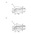
- FIG. 6 (A) and 6 (B) are enlarged views showing a distal end portion of a medical device according to a modified example of the present invention.
- the embodiment has been described in which the insertion portion 50 for inserting the medical instrument is provided on the upstream side of the position where the flow path 30 joins the conduit 41 extending from the opening 40.
- the insertion portion 50 ⁇ / b> A may be configured to be provided at a position where the flow path 30 joins the pipe line 41.
- the inner wall 38A is provided in the vicinity of the merging portion 31 as shown in FIG. 6A, and in a state where a medical instrument such as an endoscope is not inserted.
- the cross-sectional area of the flow path 30 upstream from the merge portion 31 is reduced.
- the inner wall 38A is formed of a flexible material.
- the insertion portion 50A and the inner wall 38A are provided in the vicinity of the merge portion 31 between the flow path 30 and the pipe line 41, thereby reducing the cross-sectional area in the flow path 30 compared to the case shown in FIG.
- the flow rate of the suction air passing therethrough is increased, and the cleaning liquid inflow and the cleaning effect are improved, thereby improving the cleaning power of the medical instrument.
- the embodiment in which the fluid flows through the flow path 30 by the negative pressure generating means 300 has been described.
- the negative pressure generating means can be used without using the negative pressure generating means. You may comprise so that a fluid may flow.
- FIG. 7 is an enlarged view showing a distal end portion of a medical device according to a modified example of the present invention.
- the pipe line 41 has been described with respect to the embodiment in which the axis line of the pipe line 41 is the same axis line as the axis line of the pipe line 34 as shown in FIGS. 1 and 5, the present invention is not limited to this.
- the pipe 41A is formed so that the axis of the pipe 41A intersects the axis of the flow path 34 as shown in FIG. 7, and an opening 40A, which is the end of the pipe 41A, is formed on the tip surface of the tip 10. You may form in the position which does not face.
- a flat plate portion is sufficiently secured on the distal end surface of the distal end portion 10 which has a spatula shape in the medical device 100, and insertion into a narrow portion in the living body is further improved.
- the opening 40A is formed so as to face an oblique direction from the proximal end side toward the distal end side, it can easily approach the suction target.
- the pipe 41A is inclined so that the opening 40A does not face the tip surface of the tip 10 so that the function of the tip 10 as a sonde and the function of the suction of the opening 40A can be achieved. Furthermore, both can be sufficiently achieved.
- the opening 40 functions as a suction port for sucking bodily fluid in the living body by the negative pressure generating means 300.
- the configuration of the flow path is changed, and the fluid is discharged from the medical device to the living body. Also good.
Landscapes
- Health & Medical Sciences (AREA)
- Life Sciences & Earth Sciences (AREA)
- Surgery (AREA)
- Engineering & Computer Science (AREA)
- Biomedical Technology (AREA)
- Heart & Thoracic Surgery (AREA)
- Animal Behavior & Ethology (AREA)
- General Health & Medical Sciences (AREA)
- Public Health (AREA)
- Veterinary Medicine (AREA)
- Biophysics (AREA)
- Pathology (AREA)
- Physics & Mathematics (AREA)
- Nuclear Medicine, Radiotherapy & Molecular Imaging (AREA)
- Optics & Photonics (AREA)
- Radiology & Medical Imaging (AREA)
- Medical Informatics (AREA)
- Molecular Biology (AREA)
- Hematology (AREA)
- Anesthesiology (AREA)
- Otolaryngology (AREA)
- Pulmonology (AREA)
- Endoscopes (AREA)
Description
本発明は、医療器具の生体内への挿入の支援及び医療器具の洗浄を行う医療用デバイスに関する。
生体内へは内視鏡のような医療器具を挿入することが一般的に行われている。このように生体内に内視鏡のような医療器具を挿入すると、挿入箇所によっては医療器具に粘性を有する体液などが付着することがあり、医療器具に付着した体液は手技の妨げとなる場合があるため、その際には医療器具の洗浄を行う必要が生じる。
例えば、副鼻腔炎の治療においては、鼻水のような粘性のある体液が医療器具に付着するおそれがある。また、手技を行う部位に医療器具を送達するまでには副鼻腔内に狭小な部位が存在する。特許文献1では、内視鏡と共に鼻腔内の処置において使用する医療用処置具として、医療用処置具のプローブ先端部分がへら状に形成された、いわゆるゾンデのようなものが開示されている。
特許文献1に記載されているゾンデのようなへら形状を有する医療用処置具を使用すれば、鼻腔内の狭小な部位を押し広げ、内視鏡を診断部位へと案内することができる。しかし、特許文献1のようなヘラ状の形状を備えた医療用処置具は内視鏡のような医療器具に対する洗浄機能を備えてはいない。そのため、特許文献1のような医療用処置具を使用したとしても、医療器具に鼻水等の体液が付着した場合には、一旦医療器具を生体から取り出し、ガーゼなどで拭き取った後、再び生体内に挿入する必要がある。鼻水等の体液は生体内の多くの部位に存在しており、医療器具に体液が付着する度に生体から医療器具を取り出していたのでは手技が煩雑になる、といった問題がある。
そこで本発明は、上記問題点を解決するために発明されたものであり、生体内への医療器具の円滑な挿入を支援し、かつ、医療器具を生体内へ取り出すことなく医療器具に付着した付着物を取り除くことが可能な医療用デバイスを提供することを目的とする。
上記目的を達成する本発明に係る医療用デバイスは、長尺状の本体部と、本体部の先端側に設けられ、面方向に広がる平面部を有する先端部と、本体部の基端側から先端部にかけて伸び、かつ、先端部を経由して本体部の基端側へ伸びる流体を流通可能な流路と、先端部に設けられ、医療器具の洗浄対象となる部位を流路に臨むように挿入させることが可能な挿入部と、挿入部への医療器具の挿入をガイドするガイド部と、を有する。
本発明に係る医療用デバイスは、平面部を有する先端部を備えることにより、医療器具の挿入が困難な狭小部位に先端部を当てて、押し広げる等の動作を行うことができ、医療器具の円滑な挿入を支援することができる。また、医療用デバイスは流体の流通が可能な流路を有し、流路の中でも医療用デバイスの先端部には医療器具の挿入が可能な挿入部が設けられている。また、医療用デバイスは、挿入部への医療器具の挿入をガイドするためのガイド部をも有している。そのため、ガイド部を使用して医療器具の洗浄対象部位を円滑に挿入部にまで挿入でき、医療器具を生体内から取り出すことなく医療器具に付着した付着物を取り除くことができる。
以下、添付した図面を参照しながら、本発明の実施形態を説明する。なお、以下の記載は特許請求の範囲に記載される技術的範囲や用語の意義を限定するものではない。また、図面の寸法比率は説明の都合上誇張されており、実際の比率とは異なる場合がある。
図1は本発明の一実施形態に係る医療用デバイスを示す正面図、図2は同医療用デバイスを示す平面図、図3は同医療用デバイスを示す左側面図、図4は図1の4-4線に沿う断面図、図5は同医療用デバイスの先端部を示す拡大図である。
図1~図5を参照して概説すれば、本実施形態に係る医療用デバイス100は、長尺状の本体部20と、本体部20の先端側に設けられ、面方向に広がる平面部11を有する先端部10と、本体部20の基端側から先端部10にかけて伸び、かつ、先端部10を経由して本体部20の基端側へ伸びる流体を流通可能な流路30を有する。
また、医療用デバイス100は、先端部10に設けられ、医療器具の洗浄対象となる部位が流路30に臨むように挿入させることが可能な挿入部50と、挿入部50へ医療器具の挿入をガイドするガイド部60と、を有している。
本実施形態では、流路30の上流側に水源として水槽200が接続され、下流側にポンプ等の負圧発生手段300が接続されている。先端部10には、先端部10の先端面に開口し、かつ、流路30と連通する開口部40が設けられている。負圧発生手段300により、開口部40から医療器具に付着し得る鼻水等の体液が吸引される。
また、流路30は、先端部10における挿入部50の近傍で湾曲しており、挿入部50よりも上流側の流路30の外側形状33と挿入部50よりも下流側の流路30の外側形状34とがU字状に連通して形成されている。
また、流路30には、開口部40から延びる管路41と合流する合流部31が設けられている。また、挿入部50よりも基端側には、平面部の厚み方向に貫通する医療器具のガイド用貫通穴61が設けられている。また、流路内部には挿入部50の視認を容易にする光源70が設けられている。また、基端側には医療用デバイス100への接続部としてハブ80が設けられている。以下、詳述する。
ハブ80は、医療用デバイス100と外部装置との接続部であり、羽根81、82を有する。接続時には、羽根81、82があることで容易につまむことができる。
先端部10は、内視鏡等の医療器具を診断部位まで送達するために医療器具の挿入経路上に存在する狭小な部位を押し広げられるように平面部11を有している。平面部11は、生体内の狭小な部位を押し広げられるように平面部11の先端部分の幅が本体部20の管状体の外側面よりも外側に突出するようになっている。このように平面部11の先端部分の幅が比較的大きく形成されることによって、生体内の狭小な部位と平面部11との当接する面積を十分にとることができ、平面部11によって狭小な部分を押し広げることができる。また、平面部11は、図3等に示すように、管状体の本体部20の中心軸を通るように形成されている。
本体部20は、ハブ80の先端から先端部10に至るまでに形成される管状体である。本体部20には流路30の内部を流れる流体の経路が形成されている。
流路30には、内視鏡等の医療器具のレンズ部分等の洗浄対象部位に付着した付着物を取り除くために水等の流体が流れ、開口部40から吸引された鼻水等の体液を回収するために設けられる。流路30は、基端側に流体を流す流路入り口35と、流路30を流れる流体が排出される流路出口36と、流路入り口35からの流体の流入を制御するための開放穴37と、流路30の経路上における挿入部50付近に設けられた内部壁38と、を有している。
流路入り口35は、図1に示すように水等の流体を収容した水槽200に接続されている。流路入り口35からは、水等の洗浄能力を有する流体が流れ、U字状の湾曲した先端部分を経由して流路出口36まで流れる。流路出口36は、図1に示すようにバルブ301を介してポンプ等の負圧発生手段300と接続されている。負圧発生手段300の吸引力により、流路30の上流からの流体や開口部40からの鼻水等の体液が流体出口36まで流れる。
開放穴37は、流路入り口35及び流路出口36以外に流路30の内部空間が外部と連通している部位である。負圧発生手段300を常時動作させる場合、開放穴37が外部と連通していれば、開放穴37から空気が吸引されるため、開口部40には負圧が働かず、開口部40から吸引は行われない。開放穴37の部位の内部空間が確保されるように、指等で開放穴37の部位を塞ぐことにより、開口部40から吸引が行われる。この場合、負圧は流路30を通じて開口部40にかかると共に、流路入り口35側にも印加される。流路入り口35側には内部壁38によって狭められた流路と挿入部50が備えられている。このため、通常は開放穴37を塞いで吸引行為を行うと、開口部40からは吸引対象物、流路入り口35側からは挿入部50から流入する空気が混入し、空気を巻き込みながら吸引物を吸引出来る為、効率的な吸引を行うことが出来る。さらに、開放穴37を塞いだ状態で挿入部50に洗浄対象を挿し込むと、挿入部50の開口が塞がれるため、負圧は流路30を通じて流路入り口35に印加され、水槽200から液体が流入する。流入した液体は挿入部50に挿しこまれた洗浄対象を洗い流しつつ流路出口36から吸引回収される。よって洗浄対象を洗浄したい場合、挿入部50に挿し込むだけで自動的に液体の流入が始まると共に洗浄が行われる為、より簡便に洗浄操作を行うことが出来る。
内部壁38は、図5に示すように流路30の中でも挿入部50付近に設けられた流路内部の壁である。内部壁38が設けられることにより、流路30の経路の中でも内部壁38の設けられた部位の断面積は減少することになる。これにより、断面積が減少した部位での流速が上昇し、その分、水等の流体の吸い込み力が強化でき、洗浄力をさらに強力にすることができる。
開口部40は、流路30と合流する管路41の中でも医療用デバイス100における先端部分の形状である。開口部40は、内視鏡等の医療器具を診断部位に送達させるまでの経路上に存在する医療器具に付着し得る生体内の体液等を吸引するために設けられる。開口部40及び管路41は、本実施形態において流路30の断面形状と略同一の形状をしている。また、管路41の内側面は、流路30における合流部31付近の内側面の形状と連続して接続するように形成されている。
開口部40及び管路41をこのように形成することによって、開口部40からの体液等が流路30との合流部31に堆積することなく、鼻水等の体液を吸引することができる。
合流部31は、管路41が流路30と合流する部分である。合流部31は、開口部40からの流れと流路30からの流れとが対向しないように、流路30の管路41との合流部分において流体が流れる接線方向と、管路41の流路30との合流部分において流体が流れる接線方向のなす角度とが鋭角になるように形成してもよい。
挿入部50は、本実施形態において、先端部10の側面に医療器具を挿入する挿入用貫通穴51として形成されている。挿入用貫通穴51は、流路30の中でも医療用デバイス100における先端部10の付近に設けられる。このように構成することにより、内視鏡等の医療器具を抜き出しすること無く鼻腔内にて洗浄でき、洗浄作業の簡略化、及び洗浄後再挿入時の汚れ付着を防ぐことができる。
また、挿入用貫通穴51は、本実施形態において、基端側を向くように形成されている。そのため、基端側から挿入された内視鏡等の医療器具を円滑に医療用デバイス100に挿入でき、レンズ部分等の洗浄対象部位の洗浄を迅速に行うことができる。
ガイド部60は、先端部10において先端部10の平面部から隆起した流路30の外側形状33、34を含む。また、流路30の外側形状33、34は、図1に示すように、本体部20の長手方向の任意の位置において、外側形状33及び外側形状34の距離が基端側から先端側へ近づくにつれて小さくなるように構成されている。
このように構成することによって、流路30の外側面の中でもU字形状の内側部分32に内視鏡等の医療器具を当てて先端側に進入させれば、医療器具は挿入用貫通穴51に向かうことになる。よって、医療器具を挿入用貫通穴51まで円滑にガイドすることができ、迅速に洗浄を行うことができる。
また、ガイド部60は、挿入部50の挿入用貫通穴51よりも基端側に形成された平面部11の厚み方向に貫通するガイド用貫通穴61を含む。
ガイド用貫通穴61が平面部11の厚み方向に貫通して形成されれば、いずれの平面側から進入しても内視鏡等の医療器具を貫通穴に通して挿入部50へ挿入することができ、使用者の利き手や使用時のデバイスの向きに依らず洗浄することができるため、医療器具の洗浄をさらに容易に行うことができる。
また、ガイド部60は、挿入部50である挿入用貫通穴51の縁部を凸状にした形状、および凹状に凹ませた形状のうちの少なくとも一方を含んでもよい。挿入用貫通穴51をこのように形成することによって、挿入用貫通穴51が視覚的に強調され、挿入用貫通穴51を容易に発見することができ、医療器具を挿入用貫通穴51まで円滑にガイドすることができる。
光源70は、流路30の内部に配置され、流路30の中でも医療用デバイス100の先端部分における挿入用貫通穴51の近傍に配置されている。光源70は、例えば図5に示すように長尺状の光ファイバーで構成されるが、一定以上の光量を発するものであれば、これに限定されない。光源70を流路内の挿入部近傍に配置することにより、挿入部50から光が放出され、手技者に挿入部50の位置を容易に認識させることができ、医療器具の円滑な挿入をガイドすることができる。
なお、光源70は、その先端を管路41まで延長して開口部40から臨めるように配置する、若しくは先端部の外側面に配置して、手技の対象である副鼻腔の部位を照らすようにしてもよい。このように構成することによって、内視鏡等の医療器具の使用時に必要な光源が確保され、診断部位の視野形成をさらに確実にすることができる。
次に内視鏡等の医療器具と共に用いる本実施形態に係る医療用デバイスの使用について説明する。まず、内視鏡Eを鼻空に挿入し、進入させていく。中鼻甲介の部分が狭小になっている場合、医療用デバイス100を用いて中鼻甲介の部分を押し広げ、内視鏡Eをさらに奥側へと挿入する。また、副鼻腔内には鼻水等の体液も存在するため、負圧発生手段300を動作させ、開放穴37を塞いだ状態で開口部40から鼻水等の体液を吸引して内視鏡Eへの付着を防止する。内視鏡Eのレンズ部分に鼻水等の体液が付着した場合、挿入部50に内視鏡Eを挿入する。
内視鏡Eのレンズ部分が洗浄される原理は以下のようになる。
流路出口36に負圧発生手段300を設けることにより、流路入り口35からは水等の流体が流れることができ、挿入部50からは空気が吸引され得る。空気と水の粘度の違い、及び経路長の違いによる抵抗の差により、挿入部50に内視鏡Eを挿入しない場合、合流部31よりも上流側の流路30からは、挿入用貫通穴51からの空気が流れ、開口部40から吸引される体液と共に流路出口36へと流れる。
挿入部50に内視鏡Eを挿入した場合、合流部31よりも上流側の流路30からは、挿入用貫通穴51からの空気の流入が遮断され、流路入り口35から水が流れるようになる。これにより、内視鏡Eを挿入した挿入用貫通穴51の部位の流路に水が流れるようになり、鼻水等の体液の付着した内視鏡Eのレンズ部分が洗浄される。
従来の手技では、ゾンデのようなへら状の部品を内視鏡と共に副鼻腔内に挿入し、中鼻甲介等の存在する副鼻腔中でも狭小の部位を押し広げて生体の内部にさらに進入させているが、内視鏡に体液等が付着した場合、へら部品は洗浄機能を有していない。そのため、レンズ部分に体液等が付着した場合には内視鏡を一旦生体から取り出し、ガーゼ等で拭き取った後、再び生体内に導入する必要があり、手技が煩雑なものになっている。
これに対し、本実施形態に係る医療用デバイス100には、平面部11を有する先端部10に加えて、先端部10に内視鏡を挿入する挿入用貫通穴51が設けられた流路30が形成され、挿入用貫通穴51への内視鏡の挿入をガイドするガイド部60が設けられている。そのため、内視鏡等の医療器具を生体内から取り出すことなく円滑に挿入用貫通穴51に挿入して洗浄を行うことができる。
以上説明したように、本実施形態に係る医療用デバイス100は、平面部11を有する先端部10を備えることにより、医療器具の挿入が困難な狭小部位に先端部10を当てて、押し広げる等の動作を行うことができ、医療器具の円滑な挿入を支援することができる。
また、医療用デバイス100は流体の流通が可能な流路30を有し、流路30の中でも医療用デバイス100の先端部付近には医療器具の挿入が可能な挿入部50が設けられている。さらに、医療用デバイス100は、挿入部50への医療器具の挿入をガイドするためのガイド部60をも有している。
そのため、ガイド部60を使用して医療器具の洗浄対象部位を円滑に挿入部50まで挿入でき、医療器具を生体内から取り出すことなく医療器具に付着した付着物を取り除くことができる。
また、先端部10は先端部10の先端面に開口し、かつ、流路30と連通する開口部40を有している。そのため、流路30に負圧発生手段300を接続して吸引等することにより、内視鏡等の医療器具を生体に進入させる経路上に存在する鼻水等の体液を随時吸引して取り除くことができ、医療器具に体液等を付着しにくくすることができる。
また、流路30は、先端部10において開口部40から伸びる管路41と合流する合流部31を有し、挿入部50は流路30が管路41と合流する位置よりも上流側に設けられるように配置されている。そのため、挿入部50には、開口部40からの鼻水等の体液が流れることがなく、流路30の上流側から流れる水等の流体により医療器具に付着した付着物を取り除くことができる。
また、ガイド部60は、先端部10において先端部10の平面部11から隆起した流路30の外側形状33、34を含み、流路30は本体部20の長手方向の任意の位置における挿入部50よりも上流側の外側形状33と、挿入部50よりも下流側の外側形状34との間の距離が、基端側から先端側に近づくにつれて小さくなるように構成している。
そのため、流路30の外側面の中でも外側形状33、34の中央寄りの部分32に医療器具を当てて進入させれば、医療器具を挿入部50に容易に向かわせることができ、医療器具の洗浄を迅速に行うことができる。
また、ガイド部60は、挿入部50よりも基端側に形成された平面部11の厚み方向に貫通するガイド用貫通穴61を有するように構成している。そのため、医療器具を先端部10のいずれの平面側から進入させた場合でもガイド用貫通穴61を通過させて医療器具を挿入部50に挿入することができ、医療器具の洗浄を迅速に行うことができる。
また、光源70は、挿入部50近傍を照らすように配置されているため、内視鏡等の医療器具により挿入部50を視覚的に確実に認識することができ、医療器具の挿入部50への挿入及び洗浄を迅速に行うことができる。
本発明は上述した実施形態に限定されず、特許請求の範囲において種々の変更が可能である。
図6(A)、(B)は、本発明の変形例に係る医療用デバイスの先端部を示す拡大図である。医療器具を挿入する挿入部50は、流路30が開口部40から延びる管路41と合流する位置よりも上流側に設けられる実施形態について説明した。しかし、図6に示すように挿入部50Aは、流路30が管路41と合流する位置に設けられるように構成してもよい。
挿入部50Aが、合流部31付近に設けられる場合には、内部壁38Aは図6(A)に示すように合流部31の付近に設けられ、内視鏡等の医療器具を挿入しない状態では合流部31よりも上流側の流路30の断面積を減少させる。内部壁38Aが合流部31の付近に設けられる場合、内部壁38Aは柔軟な材料で形成され、内視鏡Eを挿入すると、図6(B)に示すように流路30よりも上流側だけでなく、流路30よりも下流で、管路41からの流体の流れる経路上の断面積をも減少させるように変形する。
このように挿入部50A及び内部壁38Aが流路30と管路41との合流部31付近に設けられることによって、図5に記載した場合に比べて流路30内の断面積が減少する部位をさらに増加させて、通過する吸引空気の流速を上昇させ、洗浄液の流入及び洗浄効果を向上させることで医療器具の洗浄力を向上させることができる。
また、流路30には負圧発生手段300によって流体が流れる実施形態について説明した。しかし、医療器具を挿入しない間に挿入用貫通穴51から流体が漏れないように弁などを設けることで、医療器具を挿入しない場合にも負圧発生手段を使用せずに流路入り口35から流体を流すように構成してもよい。
図7は、本発明の変形例に係る医療用デバイスの先端部を示す拡大図である。管路41は、図1、図5に示すように管路41の軸線が管路34の軸線と同一軸線となる実施形態について説明したが、これに限定されない。
管路41Aは、図7に示すように管路41Aの軸線が流路34の軸線と交差するように形成し、管路41Aの端部である開口部40Aが先端部10の先端面には臨まない位置に形成してもよい。
このように構成することによって、医療用デバイス100の中でもへら形状にあたる先端部10の先端面は、平板部分が十分に確保され、生体内の狭小な部位への挿入がさらに良好になる。また、開口部40Aは、基端側から先端側に向かって斜め方向を向いて形成されれば吸引対象に容易にアプローチすることができる。このように、管路41Aを傾斜させ、開口部40Aが先端部10の先端面に臨まないように形成することによって、先端部10のゾンデとしての機能と開口部40Aの吸引口としての機能をさらに十分に両立させることができる。
また、開口部40は負圧発生手段300により、生体内の体液を吸引する吸引口として機能する実施形態について説明したが、流路の構成を変え、医療用デバイスから生体に流体を吐出してもよい。
10 先端部、
11 平面部、
100 医療用デバイス、
20 本体部、
200 水槽、
30 流路、
31 合流部、
32 流路の外側面、
33 基端側から先端部へ向かう流路の外側形状、
34 先端部から基端側へ向かう流路の外側形状、
35 流路入り口、
36 流路出口、
37 開放穴、
38、38A 内部壁、
300 負圧発生手段、
40 開口部、
41 管路、
50 挿入部、
51 挿入用貫通穴、
60 ガイド部、
61、61A、 ガイド用貫通穴、
70 光源、
80 ハブ、
81、82 羽根。
11 平面部、
100 医療用デバイス、
20 本体部、
200 水槽、
30 流路、
31 合流部、
32 流路の外側面、
33 基端側から先端部へ向かう流路の外側形状、
34 先端部から基端側へ向かう流路の外側形状、
35 流路入り口、
36 流路出口、
37 開放穴、
38、38A 内部壁、
300 負圧発生手段、
40 開口部、
41 管路、
50 挿入部、
51 挿入用貫通穴、
60 ガイド部、
61、61A、 ガイド用貫通穴、
70 光源、
80 ハブ、
81、82 羽根。
Claims (7)
- 長尺状の本体部と、
前記本体部の先端側に設けられ、面方向に広がる平面部を有する先端部と、
前記本体部の基端側から先端部にかけて伸び、かつ、前記先端部を経由して前記本体部の基端側へ伸びる流体を流通可能な流路と、
前記先端部に設けられ、医療器具の洗浄対象となる部位を前記流路に臨むように挿入させることが可能な挿入部と、
前記挿入部への前記医療器具の挿入をガイドするガイド部と、
を有する医療用デバイス。 - 前記先端部は、当該先端部の先端面に開口し、かつ、前記流路と連通する開口部を有する請求項1に記載の医療用デバイス。
- 前記流路は、前記先端部において前記開口部からの管路と合流する合流部を有し、
前記挿入部は、前記流路が前記管路と合流する位置よりも前記流路の上流側に設けられる請求項2に記載の医療用デバイス。 - 前記流路は、前記本体部において前記開口部からの管路と合流する合流部を有し、前記挿入部は、前記流路が前記管路と合流する位置に設けられる請求項2に記載の医療用デバイス。
- 前記ガイド部は、前記先端部において前記先端部の平面部から隆起した前記流路の外側形状を含み、
前記流路は、前記本体部の長手方向の任意の位置における前記挿入部よりも上流側の外側形状と前記挿入部よりも下流側の外側形状との間の距離が、前記基端側から前記先端部に近づくにつれて小さくなる請求項1~4のいずれかに記載の医療用デバイス。 - 前記ガイド部は、前記挿入部よりも基端側に形成された前記平面部の厚み方向に貫通する貫通穴を有する請求項1~5のいずれかに記載の医療用デバイス。
- 前記挿入部近傍を照らす光量を備えた光源がさらに設けられる請求項1~6のいずれかに記載の医療用デバイス。
Priority Applications (1)
| Application Number | Priority Date | Filing Date | Title |
|---|---|---|---|
| PCT/JP2012/068294 WO2014013583A1 (ja) | 2012-07-19 | 2012-07-19 | 医療用デバイス |
Applications Claiming Priority (1)
| Application Number | Priority Date | Filing Date | Title |
|---|---|---|---|
| PCT/JP2012/068294 WO2014013583A1 (ja) | 2012-07-19 | 2012-07-19 | 医療用デバイス |
Publications (1)
| Publication Number | Publication Date |
|---|---|
| WO2014013583A1 true WO2014013583A1 (ja) | 2014-01-23 |
Family
ID=49948437
Family Applications (1)
| Application Number | Title | Priority Date | Filing Date |
|---|---|---|---|
| PCT/JP2012/068294 Ceased WO2014013583A1 (ja) | 2012-07-19 | 2012-07-19 | 医療用デバイス |
Country Status (1)
| Country | Link |
|---|---|
| WO (1) | WO2014013583A1 (ja) |
Cited By (1)
| Publication number | Priority date | Publication date | Assignee | Title |
|---|---|---|---|---|
| GB2512696A (en) * | 2012-12-18 | 2014-10-08 | Bosch Gmbh Robert | Catheter and process for cleaning the catheter |
Citations (2)
| Publication number | Priority date | Publication date | Assignee | Title |
|---|---|---|---|---|
| US20110112363A1 (en) * | 2009-11-11 | 2011-05-12 | Fujifilm Corporation | Endoscope |
| JP2011143179A (ja) * | 2010-01-18 | 2011-07-28 | Hoya Corp | 内視鏡洗浄装置 |
-
2012
- 2012-07-19 WO PCT/JP2012/068294 patent/WO2014013583A1/ja not_active Ceased
Patent Citations (3)
| Publication number | Priority date | Publication date | Assignee | Title |
|---|---|---|---|---|
| US20110112363A1 (en) * | 2009-11-11 | 2011-05-12 | Fujifilm Corporation | Endoscope |
| JP2011120863A (ja) * | 2009-11-11 | 2011-06-23 | Fujifilm Corp | 内視鏡 |
| JP2011143179A (ja) * | 2010-01-18 | 2011-07-28 | Hoya Corp | 内視鏡洗浄装置 |
Cited By (1)
| Publication number | Priority date | Publication date | Assignee | Title |
|---|---|---|---|---|
| GB2512696A (en) * | 2012-12-18 | 2014-10-08 | Bosch Gmbh Robert | Catheter and process for cleaning the catheter |
Similar Documents
| Publication | Publication Date | Title |
|---|---|---|
| CN106063697B (zh) | 内窥镜 | |
| JP6306153B2 (ja) | 内視鏡レンズ洗浄デバイス | |
| JP6438015B2 (ja) | 変形型洗浄/吸引装置 | |
| CN102273997B (zh) | 内窥镜 | |
| CN116370730B (zh) | 引流件、内窥镜以及内窥用清洗方法 | |
| JP5989267B2 (ja) | 流体用栓部及び挿入機器 | |
| JP2022128499A (ja) | 内視鏡 | |
| JP2022010925A (ja) | ポンプチューブユニット及び内視鏡システム | |
| US11659977B2 (en) | Endoscopic device with drip flange and methods of use thereof for an operative procedure | |
| JP5855488B2 (ja) | 内視鏡 | |
| JP2005000567A (ja) | 内視鏡の観察窓洗浄装置 | |
| JP4100019B2 (ja) | 内視鏡の観察窓洗浄用流体供給機構 | |
| CN108882830A (zh) | 内窥镜 | |
| JP4953748B2 (ja) | 内視鏡の送水ノズル | |
| JP2007244796A (ja) | 内視鏡の観察窓洗浄装置 | |
| CN213251653U (zh) | 可视化引流装置 | |
| JP7566924B2 (ja) | 内視鏡 | |
| WO2022024950A1 (ja) | 内視鏡 | |
| CN222549244U (zh) | 一种自清洁的透明拉钩 | |
| JP2020058671A (ja) | 脳内血腫除去用デバイス | |
| JP2005185522A (ja) | 内視鏡,及び内視鏡の管路構造 | |
| CN118576135B (zh) | 一种能清洗内窥镜的立起台周围的内窥镜 | |
| JP2005006822A (ja) | 内視鏡およびその洗浄方法 | |
| JP2009233224A (ja) | 内視鏡先端部 | |
| JP5639234B2 (ja) | 内視鏡 |
Legal Events
| Date | Code | Title | Description |
|---|---|---|---|
| 121 | Ep: the epo has been informed by wipo that ep was designated in this application |
Ref document number: 12881311 Country of ref document: EP Kind code of ref document: A1 |
|
| NENP | Non-entry into the national phase |
Ref country code: DE |
|
| 122 | Ep: pct application non-entry in european phase |
Ref document number: 12881311 Country of ref document: EP Kind code of ref document: A1 |
|
| NENP | Non-entry into the national phase |
Ref country code: JP |