WO2014010322A1 - 歯車の歯形を面取り加工する方法 - Google Patents
歯車の歯形を面取り加工する方法 Download PDFInfo
- Publication number
- WO2014010322A1 WO2014010322A1 PCT/JP2013/064875 JP2013064875W WO2014010322A1 WO 2014010322 A1 WO2014010322 A1 WO 2014010322A1 JP 2013064875 W JP2013064875 W JP 2013064875W WO 2014010322 A1 WO2014010322 A1 WO 2014010322A1
- Authority
- WO
- WIPO (PCT)
- Prior art keywords
- gear
- tooth
- chamfering
- screw
- work
- Prior art date
- Legal status (The legal status is an assumption and is not a legal conclusion. Google has not performed a legal analysis and makes no representation as to the accuracy of the status listed.)
- Ceased
Links
Images

Classifications
-
- B—PERFORMING OPERATIONS; TRANSPORTING
- B23—MACHINE TOOLS; METAL-WORKING NOT OTHERWISE PROVIDED FOR
- B23F—MAKING GEARS OR TOOTHED RACKS
- B23F19/00—Finishing gear teeth by other tools than those used for manufacturing gear teeth
- B23F19/10—Chamfering the end edges of gear teeth
- B23F19/12—Chamfering the end edges of gear teeth by grinding
Definitions
- the present invention relates to a method for chamfering the tooth profile of a gear (work) that has been machined, hobbed or forged.
- the chamfering time can be shortened to about 1/2 as compared with the chamfering method of a tooth shape using a conventional end mill device or a tooth shape shaping device using a screw-like grindstone Even if the work material is a hard material, it has the advantage of being able to be chamfered.
- a variety of tooth shape shaping devices are commercially available and are proposed in many patent documents along with a method for beveling the tooth shape.
- rotation and feeding are given to a screw file, while rotation is also given to a gear to be processed (workpiece) to chamfer the top of a tooth profile with a screw file.
- a screw file is engaged with the tooth side surface of the gear to be processed, and the side surface is chamfered by feeding it downward to a certain extent and rotating it.
- attach the gear on the opposite side engage a screw file with the side surface of the gear of the gear, feed it to some extent, and rotate it.
- Patent Document 2 engages a gear finishing tool with a work gear (workpiece) and a second gear with this work gear, and the gear finish A method is proposed for finishing the tooth surface of the processed gear while drivingly rotating a tool.
- JP-A-3-104510 mounts a shaped gear having reference holes at both axial ends thereof such that the central axis of the shaped gear is positioned near the reference axis;
- One of a pair of conical centers opposed to each other across the mounting means on the reference axis is configured to be movable in the reference axis direction, and one conical center is brought close to the other conical center.
- the central axis of the shaped gear Centering means for causing the gear to coincide with the reference axis, a gear rotating means for rotating the shaped gear about the reference axis, a cutter for grinding the edge by contacting the edge of the shaped gear
- a cutter means having a motor for rotationally driving the cutter The cutter is mounted on the basis of the chamfering means attached to the cutter moving means, the sensor means for detecting the tooth tip of the shaped gear, and the signal from the sensor means and the profile data of the shaped gear.
- a gear tooth shape shaping apparatus characterized in that the cutter means is attached to the cutter moving means via a flexible support arm.
- Patent Document 4 discloses a burr raising means for causing a burr formed inward at an end portion of a carried-in work, and a burr fall for further lowering the raised burr to the outside.
- Means and burr removing means for removing the burr, and the gear tooth of the burr raising tool provided in the burr raising means is engaged with the tooth portion of the work while being slid in the direction of the tooth streak for burr
- the burr removal means is raised after engaging in the gear teeth of the burr falling tool provided in the burr lowering means with the teeth of the workpiece in a posture in which the axis line is inclined with respect to the work, and performing burr lowering.
- We propose a method of deburring gear end characterized in that deburring is performed using a deburring tool provided.
- this patent document 4 has a pedestal for receiving a workpiece, a burr raising tool for causing a burr formed inward at an end of the workpiece placed on the pedestal, the burr raising tool and the workpiece And a moving and holding mechanism for holding the work placed on the pedestal movably in the direction intersecting with the sliding direction,
- the tool is provided with a gear tooth that meshes with the tooth portion of the workpiece, and the gear holding end is characterized in that the workpiece is burred by moving the workpiece by the movement holding mechanism and engaging with the burr raising tool.
- JP-A-2010-184323 is a gear machining method for forming a tooth flank surface of a cutting gear which has been cut from a material, and the first shaving cutter outside the shaving standard is used to form the gear.
- the said gear cut by the 1st shaving process which performs rough finish cutting of the tooth surface of a gear to be cut, and the 2nd shaving cutter within said shaving standard (meshing pressure angle of the 1st shaving cutter and the 2nd shaving cutter) And a second shaving process for performing precision finishing cutting on the tooth surface of the tooth surface.
- Patent Document 6 Japanese Patent Application Laid-Open No. 5-269621 is a gear chamfering apparatus which rotates a gear to be processed held by a rotating device and chamfers the tooth shape corners of both surfaces of the gear with a flat grinding stone.
- a grinder supporting device capable of supporting the grinder on which the flat grinding wheel is mounted like a balance at a central portion and applying a grinding cutting force to the grinding wheel by a difference in rotational moment about the balance support point on the left and right of the grinder;
- the grinder gear radial direction moving device which moves the gear in the radial direction of the gear by the operation of a cylinder and performs positioning of the grinding wheel relative to the gear by contacting the stopper set by the stopper device, and movement of the gear radial direction moving device
- a grinder gear axial direction moving device for providing an axial movement guide on a table and moving the grinder by rotation of a screw shaft, and a length direction
- the stopper device for moving the pair of left and right movable stoppers symmetrically with the screw center formed by the left and right reverse leads at the center of the head and setting the movable stopper position according to the bevel gear diameter.
- a gear chamfering device is provided, characterized in that it is provided as a pair of devices for the upper and lower surfaces of
- Patent Document 7 discloses a work stand for holding a gear material and both chamfers on both tooth sides of the teeth of the gear material.
- a blade is attached to each swivel shaft having a different rotational direction so as to form a face, and the half circumferential region of each blade in a direction intersecting with the axis of the gear material determined by the angle of the chamfer surface is the tooth side of predetermined two teeth.
- Gear grinding machine having a tool rest for contacting and chamfering, having at least a feed mechanism for reciprocating one of the tool rest or the work stand on a coordinate plane, both stop points of the reciprocation
- a gear chamfering machine characterized in that the positional relationship between the tool rest or the work stand is set so that the working quadrants of the swivel axes of the respective cutters are switched to adjacent quadrants.
- Japanese Patent Publication No. 32-8850 Japanese Patent Application Laid-Open No. 62-24912 JP-A-3-104510 JP 7-1230 A JP, 2010-184323, A Unexamined-Japanese-Patent No. 5-269621 Japanese Patent Application Laid-Open No. 10-94921
- the twist angle of the workpiece and the tool is changed to separately chamfer the top (B portion) of the tooth form of the processed gear and the side part (A) of the tooth shape. Therefore, the chamfering time is about 1.5 times longer than the chamfering time using the milling apparatus.
- the deburring device for the gear end described in Patent Document 4 has a complicated device structure. Therefore, it is necessary to make the structure of the gear tooth shape shaping device more compact.
- the chamfering method using the end mill device of Patent Document 6 can chamfer the tooth shape even if the gear material is a hard material, and can process 91 mm in diameter, 7.5 mm in thickness, 46 teeth, and a pitch of 6.35 There is an advantage that the chamfering time of the tooth shape of the gear (work) can be performed in about one minute. However, it is required in the gear manufacturing and processing industry to chamfer this with a shaping time of 30 seconds which is about half the time.
- the object of the present invention is to propose a chamfering method capable of simultaneously performing deburring (chamfering) processing of the top (B) and the side surface (A) of the tooth shape described in Patent Document 1.
- a chamfering method capable of simultaneously performing deburring (chamfering) processing of the top (B) and the side surface (A) of the tooth shape described in Patent Document 1.
- diameter 91 mm, thickness 7.5 mm
- the invention according to claim 1 of the present invention is a screw-shaped grinding stone (g) which is fixed to a rotating shaft and is in contact with the upper outer peripheral edge of the processing gear (w) with respect to a rotating processing gear (w).
- the processed gear and the screw-like grinding stone are brought into contact with each other so that the twist angle of the outer peripheral edge is an angle ( ⁇ ) of 35 to 60 degrees, and the side surface of the tooth shape of the upper surface of the processed gear (A1, After chamfering of A2) and the tooth bottom (B1) at the same time,
- the twist angle ( ⁇ ) of the outer peripheral edge of the screw-like grindstone (g) in contact with the upper outer peripheral edge of the processed gear (w) is 35 to 60 degrees with respect to the rotating processed gear (w)
- the workpiece gear (w) and the screw-like grindstone (g) are brought into contact with each other at a certain angle to
- FIG. 1 is a process diagram of a beveling process of a tooth form.
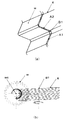
- FIG. 2 is a partial view showing a state in which a tooth shape of a gear to be processed is in contact with a screw-like grindstone
- FIG. 2 a is a perspective view
- FIG. 2 b is a plan view.
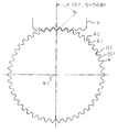
- FIG. 3 is a view showing the pressure pressure angle of the thread-like grinding wheel at the time of shaping of the teeth.
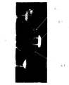
- FIG. 4 is an enlarged partial view of a tooth profile after chamfering.
- the method for chamfering the tooth profile of the gear according to the present invention as shown in FIG. 1, (1) contacts the outer periphery of the rotating workpiece gear w against the rotating workpiece gear (workpiece) w.
- the processed gear and the screw-shaped grindstone are brought into contact with each other such that the twist angle ( ⁇ ) of the outer peripheral edge of the screw-shaped grindstone (tool) g becomes an angle of 35 to 60 degrees, and the upper surface of the processed gear Surface grinding process for simultaneously chamfering both sides (A1, A2) of the tooth shape and the tooth bottom (B1) of the tooth shape,
- the twist angle ( ⁇ ) of the upper portion of the outer peripheral edge of the screw-like grindstone g in contact with the work gear is set to an angle of 35 to 60 degrees with respect to the work gear w being rotated
- the back grinding process of simultaneously chamfering both side surface parts (A1, A2) of the tooth shape of the upper surface of the work gear and the tooth bottom (B1) by bringing the work gear and the screw-like grindstone into contact with each other. To be done.
- FIG. 2 is a partial view showing a state in which the tooth shape of the processed gear w is in contact with the screw-like grindstone g at the time of tooth shape chamfering.
- gc indicates the rotation axis of the screw-like grinding wheel g.
- FIG. 2 is a partial view showing a state in which the tooth shape of the processed gear w is in contact with the screw-like grindstone g at the time of tooth shape chamfering.
- FIG. 3 is a view showing a grinding wheel pressure angle ⁇ of the screw-shaped grinding wheel g at the time of shaping of the teeth.
- w c indicates the rotation axis of the processed gear w.
- the twist angle ⁇ depends on the tooth shape, the number of teeth, the thickness, and the number of pitches of the work gear w. In the embodiment, when the twist angle ⁇ is 50 degrees, the wheel pressure angle ⁇ at the time of chamfering is about 47.5 degrees. When aiming at a chamfering angle of 45 degrees with respect to the work piece, it is optimal that the twist angle ⁇ be 53.5 to 54.5 degrees and the pressure angle ⁇ be 46.5 to 47.5 degrees.
- twist angle ⁇ be 53.5 to 54.5 degrees and the pressure angle ⁇ be 46.5 to 47.5 degrees.
- the pressure angle ( ⁇ ) of the workpiece gear w and the screw-shaped grindstone g at the time of the chamfering operation can be found at an angle within plus or minus ( ⁇ ) 3 to 7 degrees of the twist angle ( ⁇ ).
- Example 1 As the work gear w, a sintered metal work gear having a diameter of 91 mm, a thickness of 7.5 mm, an involute shape of 46 and a pitch of 6.35 was used.
- the screw-shaped grindstone (tool) g rotates at 1,500- min, which abuts on the upper outer peripheral edge of the rotating processed gear w with respect to the processed gear w rotating at 32.61- min (rpm)
- the tooth shape of the upper surface of the processed gear is made by bringing the processed gear and the screw-shaped grindstone into contact with each other so that the twist angle ( ⁇ ) of the outer peripheral edge is 50 degrees and the grinding wheel pressure angle ( ⁇ ) is 47.5 degrees. Simultaneous chamfering of the right side surface (A1), the left side surface (A2) and the tooth base (B1) was performed (surface grinding process).
- the side surface of the tooth profile after chamfering of the gear to be processed is shown in FIG. It is understood that the screw marks of the screw-like grinding wheel g are left on the chamfered tooth profile parts (side surfaces A1, A2 and the tooth bottom B1).
- the work gear w is retracted to separate the work gear w and the screw-like grindstone g, and then the work gear w is fixed on the rotating shaft with the upper surface and the lower surface reversed. (Retraction and inversion process).
- the work gear w rotating at 32.61- min is advanced to be brought into contact with the screw-like grindstone g, and then it is rotated at 32.61- min
- the twist angle ( ⁇ ) of the outer peripheral edge of a thread-like grinding stone (tool) g rotating at 1,500- min, which abuts on the upper outer peripheral edge of the rotating workpiece gear w, with respect to the processing gear (work) w is 50 degrees
- the processed gear and the screw-shaped grindstone are brought into contact with each other so that the wheel pressure angle ( ⁇ ) becomes 47.5 degrees, and the right side surface (A1) and the left side surface (A2) of the tooth shape of the upper surface of the processed gear And beveling of the tooth base (B1) was performed simultaneously (back grinding process).
- the chamfering time of one processed gear was 28 seconds.
- the above-mentioned chamfering time of 28 seconds corresponds to one half of 56 seconds of the chamfering operation time of one workpiece gear w performed by a conventional end mill machine.
Landscapes
- Engineering & Computer Science (AREA)
- Mechanical Engineering (AREA)
- Gear Processing (AREA)
Description
本発明は、シェービィング加工、ホブ加工あるいは鍛造成形された歯車(ワーク)の歯形を面取り加工する方法に関する。本発明の歯形を面取り加工する方法によれば、従来のエンドミル装置やネジ状砥石を用いる歯形整形装置を用いる歯形の面取り加工方法と比較して面取り加工時間を約1/2に短縮できるとともに、ワーク素材が硬い素材であっても面取り加工できる利点を有する。
歯車の面取り作業は、歯面に打ち傷、まくれ等があると歯車同士の噛み合わせの際に騒音や振動等が生じるので、歯車の歯形の外周、側面等の角度を少し落とし歯形面にまで傷やまくれが出ないようにするのが目的である。
歯形整形装置は、種々販売されており、また、多くの特許文献にて歯形の面取り方法とともに提案されている。例えば、特公昭32-8850号公報(特許文献1)は、ネジやすりに回転と送りを与え、一方、被加工歯車(ワーク)にも回転を与えてネジやすりによる歯形の頂部の面取り加工を行い、ついで、ネジやすりを被加工歯車の歯形側面部に噛み合わせ、ある程度下方に送り込み回転させることにより側面部の面取り加工を行う。被加工歯車の反対面の側面部の面取りを行うには、被加工歯車を反対に取り付け、ネジやすりを被加工歯車の歯形側面部に噛み合わせ、ある程度下方に送り込み回転させることにより側面部の面取り加工を行う方法を提案する。
また、特開昭62-24912号公報(特許文献2)は、歯車仕上げ加工工具と被加工歯車(ワーク)とを噛み合わせると共にこの被加工歯車に第二の歯車を噛み合わせ、前記歯車仕上げ加工工具を駆動回転しながら前記被加工歯車の歯面を仕上げ加工する方法を提案する。
特開平3-104510号公報(特許文献3)は、その軸方向両端に基準穴を有する被整形歯車を、該被整形歯車の中心軸が基準軸近傍に位置するように載置する手段と、該基準軸上に該載置手段を挟んで対向配置された一対の円錐状センタの一方を該基準軸方向に移動可能に構成し、該一方の円錐状センタを他方の円錐状センタに近接する方向に移動して、該一対の円錐状センタの先端部をそれぞれ対応する該基準穴に挿入して、該一対の円錐状センタで該被整形歯車を挟み込むことにより、該被整形歯車の中心軸を該基準軸に一致させる芯出手段と、該基準軸を中心として該被整形歯車を回転させる歯車回転手段と、該被整形歯車の縁部に接触して該縁部を研削するカッターと該カッターを回転駆動するモータを有するカッター手段を、カッター移動手段に取り付けてなる面取手段と、該被整形歯車の歯先を検出するセンサ手段と、該センサ手段からの信号と被整形歯車の歯形データに基づいて、該カッターが該被整形歯車の該縁部に接触しつつ該縁部に沿って移動するように、該歯車回転手段及び該カッター移動手段の作動を制御する手段を具備し、前記面取手段のカッターは棒状に形成されており、該カッター手段は可撓性を有するサポートアームを介して、前記カッター移動手段に取り付けられていることを特徴とする歯車の歯形整形装置を提案する。
更に、特開平7-1230号公報(特許文献4)は、搬入されたワークの端部に内向きに形成されているバリを起こすバリ起こし手段と、起こされたバリをさらに外側へ倒すバリ倒し手段と、倒されたバリを除去するバリ除去手段とを備え、前記バリ起こし手段に備えたバリ起こし工具の歯車形歯をワークの歯部と噛み合わせるとともにその歯筋方向に摺動させてバリ起こしを行い、前記バリ倒し手段に備えたバリ倒し工具の歯車形歯をワークに対し軸線が傾斜した姿勢にて該ワークの歯部と噛み合わせてバリ倒しを行った後に、前記バリ除去手段に備えたバリ取り工具を用いてバリを旋削除去することを特徴とする歯車端部のバリ取り方法を提案する。
また、この特許文献4)は、ワークを受ける受け台と、該受け台上に載置したワークの端部に内向きに形成されているバリを起こすバリ起こし工具と、該バリ起こし工具とワークとを相対的に摺動させ且つ回転させる摺動回転機構と、前記受け台上に載置したワークを摺動方向と交差する方向に移動自在に保持する移動保持機構とを設け、前記バリ起こし工具にはワークの歯部と噛み合う歯車形歯を備えさせ、前記移動保持機構によってワークを移動させ該バリ起こし工具に係合させた状態にてワークのバリ起こしを行うことを特徴とする歯車端部のバリ取り装置を提案する。
更に、特開2010-184323号公報(特許文献5)は、素材から歯切りされた被削歯車の歯面成形を行う歯車加工方法であって、シェービング基準外にある第1シェービングカッタにより、前記被削歯車の歯面の粗仕上げ切削を行う第1シェービング工程と、前記シェービング基準(第1シェービングカッタ及び第2シェービングカッタの噛合い圧力角)内にある第2シェービングカッタにより、前記被削歯車の歯面の精密仕上げ切削を行う第2シェービング工程と、を有することを特徴とする歯車加工方法を提案する。
一方、特開平5-269621号公報(特許文献6)は、回転装置に把持された被加工歯車を回転し平型研削砥石により該歯車の両面の歯形角部の面取りを行なう歯車面取装置において、前記平型研削砥石を装着したグラインダを中央部で天秤状に支持し、グラインダ左右の天秤支点まわりの回転モーメントの差で前記砥石に研削切込み力を与えることのできるグラインダ支持装置と、ガイドレール上をシリンダの作動で前記歯車の半径方向に移動し、砥石の歯車に対する位置決めをストッパ装置によりセットされたストッパに当接させて行なうグラインダ歯車半径方向移動装置と、該歯車半径方向移動装置の移動台上に軸方向移動案内部を設け、ねじ軸の回転により前記グラインダを移動させるグラインダ歯車軸方向移動装置と、長さ方向の中心部を境に左右逆リードに構成したねじ軸により左右一対の可動ストッパを歯車中心線を対称に移動させ、被面取歯車径に合せて可動ストッパ位置をセットするストッパ装置とを前記被加工歯車の上面及び下面用の1対の装置として具備したことを特徴とする歯車面取装置を提案する。
さらに、エンドミル装置を用いる歯車面取り装置も実用化され、特開平10-94921号公報(特許文献7)は、歯車材を保持する工作物台と、前記歯車材の歯の両歯側に両チャンファ面を形成すべく回転方向が異なる各スイベル軸にそれぞれ刃物を取付け、前記チャンファ面の角度によって決まる前記歯車材の軸と交差する方向に該各刃物の半周域を所定の二つの歯の歯側へ当接して面取りを行う刃物台とを有した歯車面取盤において、前記刃物台又は工作物台のうち一方を座標面上で往復運動させる送り機構を少なくとももち、その往復運動の両停止点で前記各刃物のスイベル軸同士の作動象限が隣接象限に切換わるように前記刃物台又は工作物台の位置関係を設定したことを特徴とする歯車面取盤を提案する。
上記特許文献1記載のネジやすりを用いる面取り方法は、ワークと工具の捩れ角を変えて被加工歯車の歯型の頂部(B部)と歯形の側面部(A)部を別々に面取り加工するため、ミリング装置を用いる面取り加工時間に比較して面取り加工時間が約1.5倍長く要する。
特許文献2、3および5記載の面取り加工方法は、歯車素材が硬い素材であっても歯形の面取り加工することができ、面取り加工時間も特許文献1記載の方法の2/3で行うことができる利点がある。
特許文献4記載の歯車端部のバリ取り装置は、装置構造が複雑である。よって、歯車の歯形整形装置の構造をもっとコンパクト化する必要がある。
特許文献6のエンドミル装置を用いる面取り加工方法は、歯車素材が硬い素材であっても歯形の面取り加工することができ、直径91mm、厚み7.5mm、歯形数46、ピッチ6.35の被加工歯車(ワーク)の歯形の面取り加工時間が約1分で行うことができる利点がある。しかし、この約半分の時間である30秒の整形時間で面取り加工することが歯車製造加工業界では求めている。
本発明の目的は、特許文献1記載の歯形の頂部(B)と側面部(A)のバリ取り(面取り)加工を同時に行える面取り加工方法を提案し、例えば、直径91mm、厚み7.5mm、歯形数46、ピッチ6.35の前記被加工歯車(ワーク)の歯形の面取り加工時間を約30秒で行うことができるネジ状砥石(工具)を用いる歯形整形方法の提供にある。
本発明の請求項1の発明は、回転軸に固定され、回転している被加工歯車(w)に対し、前記被加工歯車(w)の外周縁上部に当接するネジ状砥石(g)の外周縁のねじれ角が35~60度のうちのある角度(θ)となるように前記被加工歯車と前記ネジ状砥石とを当接させて前記被加工歯車の上面の歯形の側面(A1,A2)と歯底(B1)の面取り加工を同時に行った後、
前記被加工歯車(w)とネジ状砥石(g)を離間させたのち、前記被加工歯車(w)を上下逆にして前記回転軸に固定し、
ついで、回転している前記被加工歯車(w)に対し、前記被加工歯車の外周縁上部に当接するネジ状砥石(g)の外周縁のねじれ角(θ)が35~60度のうちのある角度となるように前記被加工歯車(w)と前記ネジ状砥石(g)とを当接させて前記被加工歯車の上面の歯形の側面(A1,A2)と歯底(B1)の面取り加工を同時に行うこと、を特徴とする歯車の歯形を面取り加工する方法を提供するものである。
前記被加工歯車(w)とネジ状砥石(g)を離間させたのち、前記被加工歯車(w)を上下逆にして前記回転軸に固定し、
ついで、回転している前記被加工歯車(w)に対し、前記被加工歯車の外周縁上部に当接するネジ状砥石(g)の外周縁のねじれ角(θ)が35~60度のうちのある角度となるように前記被加工歯車(w)と前記ネジ状砥石(g)とを当接させて前記被加工歯車の上面の歯形の側面(A1,A2)と歯底(B1)の面取り加工を同時に行うこと、を特徴とする歯車の歯形を面取り加工する方法を提供するものである。
被加工歯車(ワーク)とねじ状砥石(工具)の捩れ角(θ)を35~60度のうちのある角度と特定したことにより、特許文献1記載の歯車面取法における歯の頂部の面取り加工が不要となった。および、被加工歯車の歯形の面取り時間を従来のエンドミル装置を用いる面取り時間の約1/2とすることができた。
本発明の歯車の歯形を面取り加工する方法は、図1に示すように、(1)回転している被加工歯車(ワーク)wに対し、回転する被加工歯車wの外周縁上部に当接するネジ状砥石(工具)gの外周縁のねじれ角(θ)が35~60度のうちのある角度となるように前記被加工歯車と前記ネジ状砥石とを当接させて被加工歯車の上面の歯形の両側面部(A1,A2)と歯形の歯底(B1)の面取り加工を同時に行う表面研削工程、
(2)前記被加工歯車wとネジ状砥石gを離間させたのち、被加工歯車wを上面と下面を逆にして前記回転軸に固定する退避反転工程、
(3)回転している前記被加工歯車wに対し、前記被加工歯車に当接するネジ状砥石gの外周縁上部のねじれ角度(θ)が35~60度のうちのある角度となるように前記被加工歯車と前記ネジ状砥石とを当接させて被加工歯車の上面の歯形の両側面部(A1,A2)と歯形の歯底(B1)の面取り加工を同時に行う裏面研削工程、を経て行われる。
(2)前記被加工歯車wとネジ状砥石gを離間させたのち、被加工歯車wを上面と下面を逆にして前記回転軸に固定する退避反転工程、
(3)回転している前記被加工歯車wに対し、前記被加工歯車に当接するネジ状砥石gの外周縁上部のねじれ角度(θ)が35~60度のうちのある角度となるように前記被加工歯車と前記ネジ状砥石とを当接させて被加工歯車の上面の歯形の両側面部(A1,A2)と歯形の歯底(B1)の面取り加工を同時に行う裏面研削工程、を経て行われる。
図2は、歯形面取り加工時の被加工歯車wの歯形とネジ状砥石gが当接している状態を示す部分図である。gcはネジ状砥石gの回転軸芯を示す。
図2は、歯形面取り加工時の被加工歯車wの歯形とネジ状砥石gが当接している状態を示す部分図である。
図3は、歯形整形時のネジ状砥石gの砥石圧力角αを示す図である。wcは被加工歯車wの回転軸芯を示す。
ねじれ角度θは、被加工歯車wの歯形、歯数、厚み、ピッチ数に依存する。実施例では、ねじれ角度θが50度のとき、面取り加工時の砥石圧力角αは約47.5度である。ワークに対するねじ状砥石の面取角度45度狙いのときは、ねじれ角度θが53.5~54.5度、砥石圧力角αは46.5~47.5度が最適である。
ネジ状砥石による面取り作業の場合は厳密な意味では、被加工歯車wの歯数、圧力角(α)、ねじれ角(θ)等が変わればそれらに相当するモジュールのネジ状砥石gが必要とされるが、段落0002で記載したように面取り加工は単に歯形の外周および側面等の角部を少し落とすだけでよいので、各々の被加工歯車wのモジュール毎のネジ状砥石を用意しておけば、面取り作業時の被加工歯車wとねじ状砥石gのねじれ角度(θ)を35~60度の範囲内で作業者は見出すことができる。ワークに対するねじ状砥石の面取角度45度狙いのときは、ねじれ角度θが53.5~54.5度、砥石圧力角αは46.5~47.5度が最適である。面取り作業時の被加工歯車wとねじ状砥石gの圧力角(α)は、前記ねじれ角度(θ)のプラスマイナス(±)3~7度以内の角度に見出すことができる。
実施例1
被加工歯車wとして、直径91mm、厚み7.5mm、インボリュート歯形数46、ピッチ6.35の焼結金属製被加工歯車を用いた。
被加工歯車wとして、直径91mm、厚み7.5mm、インボリュート歯形数46、ピッチ6.35の焼結金属製被加工歯車を用いた。
32.61-min(rpm)で回転している前記被加工歯車wに対し、回転する被加工歯車wの外周縁上部に当接する1,500-minで回転するネジ状砥石(工具)gの外周縁のねじれ角(θ)が50度、砥石圧力角(α)が47.5度となるように前記被加工歯車と前記ネジ状砥石とを当接させて被加工歯車の上面の歯形の右側面(A1)と左側面(A2)と歯形の歯底(B1)の同時面取り加工を行なった(表面研削工程)。被加工歯車の面取り加工後の歯形側面を図4に示す。面取り加工された歯形部分(側面A1,A2および歯底B1)にはネジ状砥石gのネジマークが残されているのが理解される。
上記表面研削工程を終えた後、前記被加工歯車wを退避させて被加工歯車wとネジ状砥石gを離間させたのち、被加工歯車wを上面と下面を逆にして前記回転軸に固定した(退避反転工程)。
上記退避反転工程を終えた後、32.61-minで回転している前記被加工歯車wを前進させてネジ状砥石gと当接させ、ついで、32.61-minで回転している前記被加工歯車(ワーク)wに対し、回転する被加工歯車wの外周縁上部に当接する1,500-minで回転するネジ状砥石(工具)gの外周縁のねじれ角(θ)が50度、砥石圧力角(α)が47.5度となるように前記被加工歯車と前記ネジ状砥石とを当接させて被加工歯車の上面の歯形の右側面(A1)と左側面(A2)と歯形の歯底(B1)の同時面取り加工を行なった(裏面研削工程)。
一枚の被加工歯車の面取り作業時間は、28秒であった。
面取り加工された歯車同士を噛み合わせ回転させたところ、騒音は小さく、バリが更に落ちることはなかった。噛み合う歯車の一方の歯車歯形歯底(B1)と他方の歯車歯形歯先(B2)とは直に接触することがないので、歯形歯先(B2)は面取り加工されていなくても、いてもよい。
上記の面取り加工時間28秒は、従来のエンドミル機で行う一枚の被加工歯車wの面取り作業時間の56秒の1/2に相当する。
w 被加工歯車(ワーク)
g ネジ状砥石(工具)
θ ねじれ角
α 砥石圧力角
A1 歯形の右側面
A2 歯形の左側面
B1 歯形の歯底
B2 歯形の歯先
g ネジ状砥石(工具)
θ ねじれ角
α 砥石圧力角
A1 歯形の右側面
A2 歯形の左側面
B1 歯形の歯底
B2 歯形の歯先
Claims (1)
- 回転軸に固定され、回転している被加工歯車(w)に対し、前記被加工歯車(w)の外周縁上部に当接するネジ状砥石(g)の外周縁のねじれ角が35~60度のうちのある角度(θ)となるように前記被加工歯車と前記ネジ状砥石とを当接させて前記被加工歯車の上面の歯形の側面(A1,A2)と歯底(B1)の面取り加工を同時に行った後、前記被加工歯車(w)とネジ状砥石(g)を離間させたのち、前記被加工歯車(w)を上下逆にして前記回転軸に固定し、ついで、回転している前記被加工歯車(w)に対し、前記被加工歯車の外周縁上部に当接するネジ状砥石(g)の外周縁のねじれ角(θ)が35~60度のうちのある角度となるように前記被加工歯車(w)と前記ネジ状砥石(g)とを当接させて前記被加工歯車の上面の歯形の側面(A1,A2)と歯底(B1)の面取り加工を同時に行うこと、を特徴とする歯車の歯形を面取り加工する方法。
Applications Claiming Priority (2)
| Application Number | Priority Date | Filing Date | Title |
|---|---|---|---|
| JP2012-155173 | 2012-07-11 | ||
| JP2012155173A JP5877467B2 (ja) | 2012-07-11 | 2012-07-11 | 歯車の歯形を面取り加工する方法 |
Publications (1)
| Publication Number | Publication Date |
|---|---|
| WO2014010322A1 true WO2014010322A1 (ja) | 2014-01-16 |
Family
ID=49915796
Family Applications (1)
| Application Number | Title | Priority Date | Filing Date |
|---|---|---|---|
| PCT/JP2013/064875 Ceased WO2014010322A1 (ja) | 2012-07-11 | 2013-05-29 | 歯車の歯形を面取り加工する方法 |
Country Status (2)
| Country | Link |
|---|---|
| JP (1) | JP5877467B2 (ja) |
| WO (1) | WO2014010322A1 (ja) |
Families Citing this family (1)
| Publication number | Priority date | Publication date | Assignee | Title |
|---|---|---|---|---|
| DE102016004112A1 (de) * | 2016-04-05 | 2017-10-05 | Gleason-Pfauter Maschinenfabrik Gmbh | Verfahren zur erzeugung einer abtragung an einer zahnstirnkante und dazu ausgelegte vorrichtung |
Citations (1)
| Publication number | Priority date | Publication date | Assignee | Title |
|---|---|---|---|---|
| JPS5656339A (en) * | 1979-10-08 | 1981-05-18 | Kobe Steel Ltd | Machining method of chamfer grinding for end face of gear tooth |
-
2012
- 2012-07-11 JP JP2012155173A patent/JP5877467B2/ja active Active
-
2013
- 2013-05-29 WO PCT/JP2013/064875 patent/WO2014010322A1/ja not_active Ceased
Patent Citations (1)
| Publication number | Priority date | Publication date | Assignee | Title |
|---|---|---|---|---|
| JPS5656339A (en) * | 1979-10-08 | 1981-05-18 | Kobe Steel Ltd | Machining method of chamfer grinding for end face of gear tooth |
Also Published As
| Publication number | Publication date |
|---|---|
| JP2014014910A (ja) | 2014-01-30 |
| JP5877467B2 (ja) | 2016-03-08 |
Similar Documents
| Publication | Publication Date | Title |
|---|---|---|
| JP7224399B2 (ja) | ワークの面取り加工装置、それを備えた歯加工センタ、およびワークの面取り加工装置を用いた加工方法 | |
| JP5285416B2 (ja) | 内歯車研削盤及び樽形ねじ状工具のドレッシング方法 | |
| JP4448056B2 (ja) | カサ歯車切削機、該装置に用いるバリ取り工具、該工具が取り付けられる装置、及びカサ歯車の面取りあるいはバリ取りを行う方法 | |
| JP6012705B2 (ja) | 工作物への歯部の作製方法 | |
| TWI451926B (zh) | Internal gear machining method | |
| JP5351700B2 (ja) | 樽形ねじ状工具の製作方法 | |
| KR101254793B1 (ko) | 베벨기어 톱니선단을 모따기하거나 귀따기하는 베벨기어 절삭장치와 그 방법 | |
| JP2006026789A (ja) | 歯車研削盤 | |
| TWI414377B (zh) | Barrel - shaped tool for internal gear machining | |
| JP5318914B2 (ja) | 研削方法 | |
| JP4524159B2 (ja) | 丸形シェービングカッタの歯面を研削する方法および機器 | |
| JP5192748B2 (ja) | 面取り装置およびそれを具備する歯車加工機 | |
| CN107750197B (zh) | 研磨机和用于加工工件的方法 | |
| JP6165464B2 (ja) | 歯車研削装置 | |
| CN110267620A (zh) | 用于制作牙科修复件的方法以及牙科加工机床 | |
| JP6212418B2 (ja) | ブローチ研削盤 | |
| CN112203789B (zh) | 有齿工件的多工具倒角装置 | |
| WO2014010322A1 (ja) | 歯車の歯形を面取り加工する方法 | |
| JP5524397B2 (ja) | 樽形ねじ状工具の製作方法 | |
| JP2005118981A (ja) | 円形研削を行う方法及び装置 | |
| CN109047874B (zh) | 一种转子轴机械加工工艺 | |
| JP2005040926A (ja) | バリ取り加工装置 | |
| JP6815913B2 (ja) | ウォーム加工装置、ウォーム加工方法及びウォーム | |
| CN224088671U (zh) | 一种丝锥方形柄部加工成型装置 | |
| JP4696586B2 (ja) | ホーニング砥石のドレス方法 |
Legal Events
| Date | Code | Title | Description |
|---|---|---|---|
| 121 | Ep: the epo has been informed by wipo that ep was designated in this application |
Ref document number: 13816874 Country of ref document: EP Kind code of ref document: A1 |
|
| NENP | Non-entry into the national phase |
Ref country code: DE |
|
| 122 | Ep: pct application non-entry in european phase |
Ref document number: 13816874 Country of ref document: EP Kind code of ref document: A1 |