WO2014010293A1 - 位置検出装置、および位置検出プログラム - Google Patents
位置検出装置、および位置検出プログラム Download PDFInfo
- Publication number
- WO2014010293A1 WO2014010293A1 PCT/JP2013/062224 JP2013062224W WO2014010293A1 WO 2014010293 A1 WO2014010293 A1 WO 2014010293A1 JP 2013062224 W JP2013062224 W JP 2013062224W WO 2014010293 A1 WO2014010293 A1 WO 2014010293A1
- Authority
- WO
- WIPO (PCT)
- Prior art keywords
- position detection
- captured
- camera
- captured image
- group
- Prior art date
- Legal status (The legal status is an assumption and is not a legal conclusion. Google has not performed a legal analysis and makes no representation as to the accuracy of the status listed.)
- Ceased
Links
Images


Classifications
-
- G—PHYSICS
- G06—COMPUTING OR CALCULATING; COUNTING
- G06T—IMAGE DATA PROCESSING OR GENERATION, IN GENERAL
- G06T7/00—Image analysis
- G06T7/20—Analysis of motion
- G06T7/262—Analysis of motion using transform domain methods, e.g. Fourier domain methods
-
- G—PHYSICS
- G01—MEASURING; TESTING
- G01S—RADIO DIRECTION-FINDING; RADIO NAVIGATION; DETERMINING DISTANCE OR VELOCITY BY USE OF RADIO WAVES; LOCATING OR PRESENCE-DETECTING BY USE OF THE REFLECTION OR RERADIATION OF RADIO WAVES; ANALOGOUS ARRANGEMENTS USING OTHER WAVES
- G01S5/00—Position-fixing by co-ordinating two or more direction or position line determinations; Position-fixing by co-ordinating two or more distance determinations
- G01S5/16—Position-fixing by co-ordinating two or more direction or position line determinations; Position-fixing by co-ordinating two or more distance determinations using electromagnetic waves other than radio waves
-
- G—PHYSICS
- G06—COMPUTING OR CALCULATING; COUNTING
- G06T—IMAGE DATA PROCESSING OR GENERATION, IN GENERAL
- G06T7/00—Image analysis
- G06T7/50—Depth or shape recovery
- G06T7/55—Depth or shape recovery from multiple images
- G06T7/593—Depth or shape recovery from multiple images from stereo images
-
- G—PHYSICS
- G06—COMPUTING OR CALCULATING; COUNTING
- G06T—IMAGE DATA PROCESSING OR GENERATION, IN GENERAL
- G06T2200/00—Indexing scheme for image data processing or generation, in general
- G06T2200/04—Indexing scheme for image data processing or generation, in general involving 3D image data
-
- G—PHYSICS
- G06—COMPUTING OR CALCULATING; COUNTING
- G06T—IMAGE DATA PROCESSING OR GENERATION, IN GENERAL
- G06T2207/00—Indexing scheme for image analysis or image enhancement
- G06T2207/10—Image acquisition modality
- G06T2207/10004—Still image; Photographic image
- G06T2207/10012—Stereo images
-
- G—PHYSICS
- G06—COMPUTING OR CALCULATING; COUNTING
- G06T—IMAGE DATA PROCESSING OR GENERATION, IN GENERAL
- G06T2207/00—Indexing scheme for image analysis or image enhancement
- G06T2207/10—Image acquisition modality
- G06T2207/10016—Video; Image sequence
- G06T2207/10021—Stereoscopic video; Stereoscopic image sequence
-
- G—PHYSICS
- G06—COMPUTING OR CALCULATING; COUNTING
- G06T—IMAGE DATA PROCESSING OR GENERATION, IN GENERAL
- G06T2207/00—Indexing scheme for image analysis or image enhancement
- G06T2207/20—Special algorithmic details
- G06T2207/20048—Transform domain processing
-
- G—PHYSICS
- G06—COMPUTING OR CALCULATING; COUNTING
- G06T—IMAGE DATA PROCESSING OR GENERATION, IN GENERAL
- G06T2207/00—Indexing scheme for image analysis or image enhancement
- G06T2207/20—Special algorithmic details
- G06T2207/20076—Probabilistic image processing
-
- G—PHYSICS
- G06—COMPUTING OR CALCULATING; COUNTING
- G06T—IMAGE DATA PROCESSING OR GENERATION, IN GENERAL
- G06T2207/00—Indexing scheme for image analysis or image enhancement
- G06T2207/20—Special algorithmic details
- G06T2207/20081—Training; Learning
-
- G—PHYSICS
- G06—COMPUTING OR CALCULATING; COUNTING
- G06T—IMAGE DATA PROCESSING OR GENERATION, IN GENERAL
- G06T2207/00—Indexing scheme for image analysis or image enhancement
- G06T2207/30—Subject of image; Context of image processing
- G06T2207/30248—Vehicle exterior or interior
- G06T2207/30252—Vehicle exterior; Vicinity of vehicle
Definitions
- the present invention relates to a position detection device and a position detection program for detecting the position of an object in a captured image based on a plurality of captured images.
- a position detection device for detecting the position of an object in a captured image with higher accuracy based on a plurality of captured images and a position detection program for realizing a position detection method are provided. It is an object of the present invention to do this.
- the position detection device wherein the image coordinate group acquisition unit is configured to achieve a first object including a plurality of captured images captured at a reference period representing a preset period. An image representing the coordinates of the object in each captured image that constitutes the second captured image group that is shifted in timing by an asynchronous time with respect to the imaging timing of the image group and the first captured image group and that is captured in the reference period Each coordinate group is acquired.
- the position calculation unit calculates the position of the object from each image coordinate group based on the relationship that the first captured image group and the second captured image group are shifted by an asynchronous time.
- the frequency waveform calculation unit includes a first trajectory indicating a transition along a time series of image coordinate groups obtained from the first captured image group, and a second captured image group.
- the first trajectory based on the first trajectory and the second frequency waveform based on the second trajectory are calculated by performing Fourier transform on the second trajectory indicating the transition along the time series of the image coordinate group obtained from To do.
- the position calculation unit calculates the position of the object based on the relationship that the first frequency waveform and the second frequency waveform are shifted by a phase corresponding to the asynchronous time.
- the position detection apparatus since the first captured image group and the second captured image group have a relationship shifted by an asynchronous time, the position detection apparatus has independent information regarding the frequency characteristics of the position of the object.
- the position of the object is calculated using this independence.
- each waveform obtained by performing Fourier transform on the locus of the image coordinate group in each captured image group that is captured with the timing shifted by the asynchronous time has a phase component corresponding to the asynchronous time.
- the position of the object is calculated based on the fact that the relationship is shifted by a certain amount.
- the position of the object at the time when each captured image is obtained can be detected, so compared with a configuration in which the position of the object is detected based on the synchronized captured image group.
- the position of the object can be detected with higher accuracy.
- the image coordinate group based on the first captured image group and the second captured image group is acquired.
- the imaging for acquiring the first captured image group and the second captured image group is performed.
- the position detection device of the present invention may use an image coordinate group based on the third captured image group, the fourth captured image group, or the like. That is, the configuration for acquiring the image coordinate group based on the first captured image group and the second captured image group is the minimum necessary configuration for realizing the present invention, and in addition, the third captured image group and the fourth captured image group. If an image coordinate group based on a plurality of captured image groups can be acquired by using an image coordinate group based on an image group or the like, the effect of the present invention can be realized.
- the position calculation unit may detect the position of the object in the following procedure, for example.
- each trajectory first trajectory and second trajectory
- the frequency waveform is subjected to inverse Fourier transform to obtain functions representing the first trajectory and the second trajectory, respectively, and further, the time at which the position of the object is to be obtained is substituted into these functions. Find the position of.
- positioning shows that the direction of the imaging center axis
- the configuration and function of the position detection device may be realized using a software program.
- the present invention by intentionally shifting the imaging timing between a plurality of cameras, even high frequency components that cannot be restored by the normal stereo method with the matching imaging timing are obtained.
- a method and a position detection apparatus for accurately restoring three-dimensional images are proposed.
- the proposed method it is possible to three-dimensionally restore up to higher frequency components as the number of cameras that are not synchronized (the imaging timing is shifted) is increased to three and four.
- a camera whose imaging timing matches is referred to as a synchronous camera, and a case where the imaging timing does not match is referred to as an asynchronous camera.
- a stereo camera deliberately shifting the imaging cycle can obtain higher-density information that cannot be obtained by a conventional stereo camera, but each of these cameras is in a three-dimensional space. Since different points are imaged, there is no correspondence between the points on the obtained image. For this reason, three-dimensional restoration cannot be performed using a normal stereo restoration method.
- FIG. 2 (a) the trajectory of a three-dimensional point in the real space (a point on the obtained image) is Fourier transformed, and as shown in FIG. 2 (b), Consider the projection of a 3D point in frequency space.
- a camera that projects different points due to a period shift in real space can be expressed as a projection model that projects the same three-dimensional point in frequency space.
- a correspondence relationship is created between the images of the asynchronous camera, and the three-dimensional point can be restored.
- the position detection device 1 having a function of restoring a three-dimensional point using an asynchronous camera is mounted on a vehicle such as a passenger car, for example. As shown in FIG. In the embodiment, two imaging units 21 and 22 and a traveling state detection unit 23 are provided.
- the arithmetic unit 10 is configured as a well-known computer (arithmetic apparatus) including a CPU 11 and a memory 12 such as a ROM and a RAM.
- the CPU 11 includes a software program (including a position detection program) stored in the memory 12 and the like. Process based on.
- the imaging units 21 and 22 are configured as well-known affine cameras, and each imaging unit is arranged so that most of the imaging regions overlap at different positions.
- the imaging units 21 and 22 are arranged in parallel so that the direction of the central axis of the camera is parallel to the outside.
- the imaging units 21 and 22 do not have to be arranged in parallel, and can be arbitrarily arranged.
- the image capturing units 21 and 22 perform image capturing for each reference period (for example, 30 fps) which is the same period, but the image capturing timing is set to be shifted by a preset asynchronous time.
- the imaging units 21 and 22 send the captured images to the calculation unit 10.
- the traveling state detection unit 23 is configured as a combination of sensors that detect the traveling state of the vehicle, such as a vehicle speed sensor and a steering angle sensor. The traveling state detection unit 23 sends each detected sensor value to the calculation unit 10.
- the calculation unit 10 performs the following position and distance detection processing.
- the position and distance detection processing is, for example, processing that is started when the power of the position detection device 1 is turned on, and then repeatedly executed at a predetermined cycle.
- the latest captured image by the imaging unit 21 or 22 is acquired, and this image is recorded in the memory 12 (S110). Then, the image feature amount of this image is calculated (S120).
- the image feature amount corresponds to HOG (Histogram of Gradient) or the like for extracting the luminance gradient and luminance intensity.
- the object is recognized based on the image feature amount, and the target object is recognized (S130).
- an object to be detected is detected from the image using functions such as generally known machine learning and support vector machines based on the image feature amount.
- the position of the object is temporarily registered in the memory 12 (S140). Specifically, the coordinate area and identification number on the image of the current object are registered.
- the object here is, for example, a vehicle, and the position of the object is an arbitrary coordinate of the object (for example, the position of the taillight). Note that the position of the object may be, for example, the coordinates of the center of the object or the coordinates closest to the imaging units 21 and 22 of the object (coordinates closest to the image center).
- the position history of the object is acquired from the memory 12 (S150), and the vehicle information is acquired (S160).
- the position history of the object indicates past positions of a large number of objects accumulated in the memory 12 every time the process of S140 is performed.
- the vehicle information is data indicating information such as a vehicle speed and a steering angle representing a traveling state of the host vehicle, a relative speed with respect to an object, and the like, and is appropriately stored in the memory 12.
- the object detected this time takes into account the latest object position, the position history of the object excluding the latest object, and vehicle information (such as the vehicle trajectory and relative speed with the object) It is determined whether or not they are the same (S170).
- vehicle information such as the vehicle trajectory and relative speed with the object
- the position of the past object is tracked in consideration of the identification number of the object, and it is determined whether the latest position of the object is far from the position of the object detected in the past.
- the matching object is formally recorded in the memory 12, and the non-matching object is deleted from the memory 12 when the host vehicle has traveled a certain distance or after a lapse of a certain time (S180). Subsequently, an object position calculation process described later is performed (S190).
- the relative distance (object distance) between the coordinates of the object and the imaging units 21 and 22 is determined.
- the coordinates of the object are obtained by performing the following process.
- the imaging unit 21 is described as the first camera
- the imaging unit 22 is described as the second camera.
- the camera projection model is first considered in the frequency space.
- the camera matrix of the first camera is P (known for each camera), and the point in the three-dimensional space at time t
- This projection formula can be expressed as follows.
- the camera matrix of the second camera is P ′ (known for each camera), and the point in the three-dimensional space at time t ′ different from time t
- This projection formula can be expressed as follows.
- Equation (1) discrete Fourier transform
- the projection type discrete Fourier transform in the first camera is as follows.
- the projection type discrete Fourier transform in the second camera is as follows.
- Equation (6) is rewritten as follows.
- Equation (7) can be rewritten as follows.
- the sampling time shift in the normal space is regarded as a phase shift in the frequency space, and can be regarded as the depth of the camera projection in the normal space by setting ⁇ (n).
- the projection expression in the frequency space can be obtained by performing the Fourier transform on the projection expression in the normal space.
- equation (11) is replaced as follows.
- the three-dimensional point Z (n) to be obtained is obtained as a least square solution using the inverse matrix M ⁇ 1 of M as follows.
- the three-dimensional point X (t ′) projected by the second camera can be expressed as follows in the frequency space by Fourier transform.
- the projection on the projection camera can be considered by replacing it with the projection on the affine camera in a pseudo manner, and as a result, it can be restored from the asynchronous camera via the frequency space. Therefore, in the following, a method for three-dimensional restoration from an image of an asynchronous projection camera using such properties will be described.
- this projection can be expressed as follows.
- ⁇ and ⁇ ′ are projection depths in the respective cameras, and these are generally different in the two cameras.
- these two projection cameras are arranged such that their optical axes are parallel to each other and a straight line connecting the optical centers of the two cameras is parallel to the image plane.
- parallel stereo such a camera arrangement is referred to as parallel stereo.
- the depths (Z coordinates) of the three-dimensional points X viewed from the respective cameras are equal to each other. That is, the following relationship holds between the projection depth ⁇ of the first camera and the projection depth ⁇ ′ of the second camera.
- Equation (17) and Equation (18) are equal in Equation (17) and Equation (18). Due to this property, equations (17) and (18) can be rewritten as:
- YY is a three-dimensional coordinate as shown in the following equation:
- the camera matrices P and P ′ are projection camera matrices, but their projections can be expressed by a linear projection model in the same way as an affine camera. Further, from equation (22), it can be seen that if YY can be obtained, XX can be obtained by dividing YY by the element in the fourth row of YY.
- YY is estimated using the linear projection models of Equation (20) and Equation (21), and XX is calculated from the obtained YY, so that the linear projection model is exactly the same as the affine camera. 3D restoration can be performed. Therefore, in the present embodiment, consider obtaining YY instead of XX.
- ZY (Hereinafter also referred to as “ZY”)
- Yt (Hereinafter referred to as “Yt”. Also, “t” where t is replaced with “t ′”) is a discrete Fourier transform. From these equations, ZY can be restored exactly as described above. Then, Yt is obtained by performing inverse discrete Fourier transform on the restored ZY.
- Yt ′ is also obtained by multiplying ZY by ⁇ (n) ⁇ 1 and then performing inverse discrete Fourier transform. Obtained in this way
- the calculation unit 10 (CPU 11) includes a first captured image group including a plurality of captured images captured at a reference cycle representing a preset cycle, and the first Each of the image coordinate groups representing the coordinates of the object in each captured image constituting the second captured image group captured at the reference period is shifted with respect to the imaging timing of the captured image group. To do.
- the computing unit 10 also includes a first trajectory indicating a transition along the time series of the image coordinate group obtained from the first captured image group and a time series of the image coordinate group obtained from the second captured image group.
- the second trajectory indicating the transition is Fourier transformed to calculate the first frequency waveform based on the first trajectory and the second frequency waveform based on the second trajectory.
- the calculating part 10 calculates the position of a target object based on the 1st frequency waveform and the 2nd frequency waveform being the relationship which shifted
- each waveform obtained by Fourier transforming the trajectory of the image coordinate group in each captured image group captured with the timing shifted by the asynchronous time has a phase component corresponding to the asynchronous time.
- the position of the object is calculated based on the fact that the relationship is shifted by a certain amount. Therefore, according to such a position detection device 1, the position of the object at the time when each captured image is obtained can be detected. Therefore, the position detection apparatus 1 is compared with the configuration in which the position of the object is detected based on the synchronized captured image group. Thus, the position of the object can be detected with higher accuracy.
- the position detection device 1 calculates the distance to the object based on the position of the object. According to such a position detection apparatus 1, since it is also possible to calculate the distance to the object, another control according to the distance to the object can be performed.
- each captured image group is acquired from a plurality of cameras arranged in parallel. According to such a position detection apparatus 1, even when a projection camera is used (when an affine camera is not used), the position of the object can be detected satisfactorily.
- a stereo with a base line length of 10 cm or less is used to restore the distance to this vehicle.
- the restoration accuracy of the proposed method in restoration was evaluated.
- the left and right lights of the vehicle were tracked to obtain coordinate data.
- An mxm correlation tracker was used for tracking. Since the size of the vehicle light in the image changes greatly according to the distance, the size m of the tracker changes according to the size of the light, and the size of the light changes by sequentially updating the template. Even so it was properly tracked.
- the coordinate value was obtained by taking a moving average of 5 times at each time. Then, in order to simulate the case where the camera of the same frame rate is photographed synchronously and asynchronously in the conventional method and the proposed method, the conventional method uses only 30 frames at an odd time in an image at 60 time, Used 30 frames at odd times for images obtained from the first camera and 30 frames at even times for images obtained from the second camera.
- feature point data of 30 frames of synchronous camera was created in the conventional method, and feature point data of 30 frames of asynchronous camera was created and used in the proposed method.
- the proposed method since the discrete Fourier transform assumes a periodic function, the obtained linear data is turned back into a pseudo periodic function, and the first half of the restored point is used as the restoration result.
- the distance between the three-dimensional points used in this experiment is in the range of several meters to several tens of meters.
- the restoration result is greatly scattered in the depth direction and correct. Restoration is not possible. This can be said to be a natural result because the stereo camera with a baseline length of 10 cm or less is restored under extremely severe conditions.
- the three-dimensional points are restored at approximately equal intervals within a range of several meters to several tens of meters, so that the restoration can be performed well. I understand.
- a line C indicates a true value (correct depth).
- a camera image generally has two-dimensional information of X and Y
- the frequency obtained by Fourier transforming these images The number of elements in the region is 2 KM, and the number of independent frequency elements is KM.
- the number of elements in the frequency domain necessary for expressing this is 3N, and among these, (3/2) N independent frequency elements are included. is there.
- three-dimensional information including the same high-frequency component as that observed at four times can be restored from an image observed at three times (three imaging cycles) with two cameras.
- the same three-dimensional point is observed with two cameras in a normal stereo camera, there is a dependency on the information obtained from the image, and such restoration cannot be performed.
- each camera observes a different three-dimensional point, so that independent information can be obtained, and a high-frequency three-dimensional signal can be restored according to equation (28).
- ⁇ is a scalar variable and represents the projected depth during projection.
- the projection onto each camera can be expressed as follows.
- M is a (2KM) ⁇ (3N +1) matrix shown below.
- Z 4 is the fourth row of Z (n), and L i is
- Txi and Tyi are vectors composed of X and Y coordinates for M times in the image of the i-th camera as in the following equation.
- Equation (31) represents that the frequency component of the three-dimensional motion can be linearly expressed by the image obtained from the asynchronous camera. Therefore, when the inequality of Expression (28) holds, the N frequency components f of the three-dimensional motion point can be restored from the asynchronous image at the M time as the eigenvector corresponding to the minimum eigenvalue of MtM.
- Mt represents a transposed matrix of the matrix M.
- a frequency component is obtained based on the relationship between the position of the object in real space and the frequency component obtained by Fourier transforming the locus of the position, and the frequency component is Based on this, the position of the object is calculated.
- the position and distance detection method described in the above embodiment can be further extended to a projection stereo camera having an arbitrary arrangement. Specifically, it is assumed that there are two projection cameras arranged at arbitrary positions and orientations. At this time, prepare a flat plate depicting four points whose coordinates on the plane are known, and place the flat plate in front of the camera so that the straight line connecting the optical centers of the two cameras and this flat plate are parallel. Arrange and image four points on the flat plate.
- a plane projection transformation is calculated from the coordinates on the flat plate of these four points and the coordinates in the camera image, and the entire camera image is transformed by this plane projection transformation, so that the camera is virtually arranged parallel to the plane. it can.
- the two converted images become images captured in a parallel stereo arrangement.
- restoration by the above-described method can achieve high-density restoration by de-synchronizing even in a general-purpose projection stereo camera. it can.
- the method described above can be extended to N multi-cameras as they are.
- the optical centers of these N cameras need to be on the same straight line.
- the optical centers are on the same straight line, it is possible to obtain a parallel multi-camera state in which all the cameras are parallelized by virtually parallelizing using the method described above.
- by restoring using the frequency domain normal N times higher density restoration can be performed by N cameras.
- a plurality of cameras are used.
- a plurality of captured image groups with one camera that performs a periodic motion such as a circular motion or a reciprocating motion. May be obtained.
- the example which mounts the position detection apparatus 1 in a vehicle was described in the said embodiment, it can arrange
- the process of S150 corresponds to the image coordinate group acquisition unit of the present invention
- the process of S190 includes the frequency waveform calculation unit and the position calculation of the present invention. It corresponds to the part.
- the process of S200 corresponds to a distance calculation unit.
Landscapes
- Engineering & Computer Science (AREA)
- Physics & Mathematics (AREA)
- General Physics & Mathematics (AREA)
- Computer Vision & Pattern Recognition (AREA)
- Theoretical Computer Science (AREA)
- Electromagnetism (AREA)
- Radar, Positioning & Navigation (AREA)
- Remote Sensing (AREA)
- Mathematical Physics (AREA)
- Multimedia (AREA)
- Length Measuring Devices By Optical Means (AREA)
- Image Analysis (AREA)
Abstract
位置検出装置においては、予め設定された周期を表す基準周期で撮像された複数の撮像画像からなる第1撮像画像群、および基準周期かつ非同期時間だけタイミングをずらして撮像された第2撮像画像群、を構成する各撮像画像中における対象物の座標を表す画像座標群をそれぞれ取得する。そして、各撮像画像群から得られた画像座標群の時系列に沿った遷移を示す第1軌跡および第2軌跡、をそれぞれフーリエ変換することで、第1軌跡に基づく第1周波数波形、および第2軌跡に基づく第2周波数波形を演算し、各周波数波形が非同期時間に応じた位相分だけずれた関係であることに基づいて対象物の位置を演算する。
Description
本発明は、複数の撮像画像に基づいて撮像画像中の対象物の位置を検出する位置検出装置、および位置検出プログラムに関する。
従来の位置検出装置として、同期した複数のカメラを用いて対象物の位置を検出する、いわゆるステレオカメラとしての構成を有するものが知られている(例えば、特許文献1参照)。
しかしながら、上記の従来の位置検出装置では、同期したカメラの撮像周期よりも分解能を向上させることができないという問題点があった。そこで、このような従来の問題点を鑑み、複数の撮像画像に基づいて撮像画像中の対象物の位置をより高精度に検出する位置検出装置、および位置検出方法を実現する位置検出プログラムを提供することを本発明の目的とする。
かかる目的を達成するために成された請求項1に記載の位置検出装置において、画像座標群取得部は、予め設定された周期を表す基準周期で撮像された複数の撮像画像からなる第1撮像画像群、および第1撮像画像群の撮像タイミングに対して非同期時間だけタイミングをずらし、かつ基準周期で撮像された第2撮像画像群、を構成する各撮像画像中における対象物の座標を表す画像座標群をそれぞれ取得する。
また、位置演算部は、第1撮像画像群と第2撮像画像群とが非同期時間だけずれた関係であることに基づいて、各画像座標群から対象物の位置を演算する。また、請求項2に記載の位置検出装置において、周波数波形演算部は、第1撮像画像群から得られた画像座標群の時系列に沿った遷移を示す第1軌跡、および第2撮像画像群から得られた画像座標群の時系列に沿った遷移を示す第2軌跡、をそれぞれフーリエ変換することで、第1軌跡に基づく第1周波数波形、および第2軌跡に基づく第2周波数波形を演算する。そして、位置演算部は、第1周波数波形と第2周波数波形とが非同期時間に応じた位相分だけずれた関係であることに基づいて、対象物の位置を演算する。
すなわち、本発明の位置検出装置では、第1撮像画像群と第2撮像画像群とが非同期時間だけずれた関係であるために、対象物の位置の周波数特性に関する独立な情報を持っていることに着目して、この独立性を利用して対象物の位置を演算する。特に、請求項2に係る発明では、非同期時間だけタイミングをずらして撮像された各撮像画像群中の画像座標群の軌跡をフーリエ変換することで得られる各波形が、非同期時間に応じた位相分だけずれた関係であることに基づき対象物の位置を演算する。
したがって、このような位置検出装置によれば、各撮像画像が得られた時刻における対象物の位置を検出できるので、同期した撮像画像群に基づいて対象物の位置を検出する構成と比較して、より高精度に対象物の位置を検出することができる。
なお、本発明の位置検出装置においては、第1撮像画像群および第2撮像画像群に基づく画像座標群を取得するよう構成したが、第1撮像画像群および第2撮像画像群を取得する撮像画像群取得部(S110)や、これらの各撮像画像群から画像座標群をそれぞれ抽出する画像座標群抽出部(S140)を備えていてもよい。
また、本発明の位置検出装置は、第3撮像画像群や第4撮像画像群等に基づく画像座標群を利用してもよい。つまり、第1撮像画像群および第2撮像画像群に基づく画像座標群を取得する構成は本発明を実現するための必要最低限の構成であり、それに加えて第3撮像画像群や第4撮像画像群等に基づく画像座標群を利用することで、複数の撮像画像群に基づく画像座標群を取得できれば、本発明の効果を実現することができる。
また、本発明において位置演算部は、例えば、以下の手順で対象物の位置を検出すればよい。まず、各軌跡(第1軌跡および第2軌跡)をフーリエ変換し、周波数空間において周波数波形を特定する。そして、この周波数波形を逆フーリエ変換することで前記第1軌跡および前記第2軌跡を表す関数をそれぞれ求め、さらにこれらの関数に対象物の位置を求めたい時刻を代入することによって、前記対象物の位置を求める。
なお、請求項3に係る発明において平行配置とは、射影カメラの撮像中心軸の方向が互いに平行または略平行になっていることを示す。また、上記目的を達成するためには、上記位置検出装置の構成および機能をソフトウエアプログラムを用いて実現してもよい。
以下に本発明にかかる実施の形態を図面と共に説明する。
[本発明の概要]
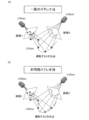
カメラ画像に基づく3次元復元法としてとしては様々な方法が提案されているが、図1(a)に示すように、複数のカメラの視差情報に基づくステレオ法が最も広く用いられている有用な方法である。通常、ステレオ法を用いてカメラ画像から3次元点を復元するためには、これらのカメラでは3次元空間中の同じ点を投影する必要がある。
[本発明の概要]
カメラ画像に基づく3次元復元法としてとしては様々な方法が提案されているが、図1(a)に示すように、複数のカメラの視差情報に基づくステレオ法が最も広く用いられている有用な方法である。通常、ステレオ法を用いてカメラ画像から3次元点を復元するためには、これらのカメラでは3次元空間中の同じ点を投影する必要がある。
このため、時間的に変化する動的なシーンを復元する場合には、複数のカメラ間において同期を取り、撮像タイミングを一致させる必要がある。撮像タイミングが一致した同期カメラの場合には、図1(a)に示すように、複数のカメラにおいて同じ3次元点を観測することができるため、得られた画像上の点には対応関係が存在し、3次元点を復元することができる。
しかし、複数のカメラ間で撮像タイミングが一致している必要があるので、通常のステレオ復元においては、カメラのサンプリングレート以上の高周波成分は復元することができない。もしもカメラのサンプリング周波数の1/2以上の高周波成分を含む3次元運動をカメラで観測した場合には、3次元復元結果にエイリアシングの問題が発生し、復元精度が低下する。
そこで本発明(第1実施形態)では、図1(b)に示すように複数のカメラ間において撮像するタイミングをわざとずらすことにより、撮像タイミングの一致した通常のステレオ法では復元できない高い周波数成分まで正確に3次元復元する手法および位置検出装置を提案する。提案法(本発明)では、同期しない(撮像タイミングのずれた)カメラの台数を3台、4台と増やすにつれて、より高い周波数成分までを3次元復元することが可能となる。本明細書では、以降、撮像タイミングが一致したカメラを同期カメラと呼び、撮像タイミングが一致していない場合を非同期カメラと呼ぶことにする。
図1(b)に示すように、撮像周期をわざとずらしたステレオカメラでは、従来のステレオカメラでは得られないより密度の高い情報を得ることができるが、これらのカメラはそれぞれ3次元空間中の異なる点を撮像しているため、得られた画像上の点には対応関係が存在しない。このため通常のステレオ復元法を用いて3次元復元することはできない。
しかし、本発明では、複数カメラにおける撮像タイミングのずれが既知の条件下で周波数空間を介して3次元復元を行うことにより、各カメラのサンプリング周波数を上回る高周波な3次元運動を正確に復元する方法および位置検出装置を提案する。
このため本発明では、まず、図2(a)に示すように、実空間の3次元点(得られた画像上の点)の軌跡をフーリエ変換し、図2(b)に示すように、周波数空間において3次元点の投影を考える。
周波数空間の情報に変換することで、実空間においては周期ずれのため異なる点を投影しているカメラが、周波数空間においては同一の3次元点を投影する投影モデルとして表現することが可能となる。このように周波数空間では同一の3次元点を投影していることになるため非同期カメラの画像間に対応関係が生まれ、3次元点を復元することが可能となる。
次に、第2実施形態では、この周波数空間における投影モデルをさらに拡張することで、カメラのサンプリング周波数の制約を受けずに高周波な3次元運動を非同期カメラにより復元する位置および距離検出方法および位置検出装置を示す。この結果、本発明ではK台のカメラから通常の2/3K倍の高周波成分までが復元可能であることを示す。
例えば、2台の非同期カメラで3次元復元した場合には、通常のステレオカメラのサンプリング周波数を4/3倍にアップして高密度にサンプリングして3次元復元した場合と同じ復元結果が得られる。この効果はカメラの台数を増やすと飛躍的に向上し、3台の非同期カメラを用いた場合には、カメラのサンプリング周波数を2倍にアップして3次元復元した効果が得られ。6台の非同期カメラを用いると4倍の高密度サンプリングによる3次元復元が実現できる。
[第1実施形態]
[本実施形態の構成]
以下に本実施形態の具体的構成について説明する。
[本実施形態の構成]
以下に本実施形態の具体的構成について説明する。
上記のように非同期カメラを用いて3次元点を復元する機能を有する位置検出装置1は、例えば乗用車等の車両に搭載されており、図3に示すように、演算部10と、複数(本実施形態では2つ)の撮像部21,22と、走行状態検出部23と、を備えている。
演算部10は、CPU11や、ROM、RAM等のメモリ12を備えた周知のコンピュータ(演算装置)として構成されており、CPU11はメモリ12に格納されたソフトウエアプログラム(位置検出プログラムを含む)等に基づく処理を行う。
撮像部21、22は、周知のアフィンカメラとして構成されており、それぞれの撮像部は、異なる位置にて撮像領域の大部分が重複するように配置されている。また、撮像部21、22は、カメラの中心軸の向きが対外に平行となる平行配置とされている。なお、本実施形態の場合のように、撮像部21、22がアフィンカメラである場合には、平行配置である必要はなく、撮像部21、22は任意の配置を取り得る。
さらに、撮像部21、22は、同一の周期である基準周期ごと(例えば30fps)に撮像を行うが、撮像タイミングは予め設定された非同期時間だけずらして設定されている。撮像部21、22は、撮像した画像を演算部10に送る。
走行状態検出部23は、車速センサや舵角センサ等の、車両の走行状態を検出するセンサの組み合わせとして構成されている。走行状態検出部23は、検出した各センサ値を演算部10に送る。
[本実施形態の処理]
上記のように構成された位置検出装置1において演算部10は、以下に示す位置および距離検出処理を実施する。位置および距離検出処理は、例えば、位置検出装置1の電源が投入されると開始され、その後、所定の周期で繰り返し実行される処理である。
上記のように構成された位置検出装置1において演算部10は、以下に示す位置および距離検出処理を実施する。位置および距離検出処理は、例えば、位置検出装置1の電源が投入されると開始され、その後、所定の周期で繰り返し実行される処理である。
位置および距離検出処理では、まず、図4に示すように、撮像部21または22による最新の撮像画像を取得し、この画像をメモリ12に記録する(S110)。そして、この画像の画像特徴量を算出する(S120)。ここで、画像特徴量とは、輝度勾配・輝度強度を取り出すHOG(Histogram of Gradient)等が該当する。
続いて、画像特徴量に基づいて物体を認識し、対象物を認識する(S130)。この処理では、画像特徴量に基づいて、一般的に知られている機械学習やサポートベクターマシン等の機能を用いて検出すべき対象物を画像内より検出する。
そして、対象物の位置をメモリ12に仮に登録する(S140)。具体的には、現在の対象物の画像上の座標領域、識別番号を登録する。ここでの対象物は、例えば車両であり、対象物の位置としては、対象物の任意の座標(例えばテールライトの位置)である。なお、対象物の位置は、例えば、対象物の中心の座標でもよいし、対象物の撮像部21、22に最も近い座標(画像中心に最も近い座標)でもよい。
次に、対象物の位置履歴をメモリ12から取得し(S150)、車両情報を取得する(S160)。ここで、対象物の位置履歴とは、S140の処理が実施される度にメモリ12に蓄積された、多数の対象物の過去の位置を示す。また、車両情報とは、自車両の走行状態を表す車速や舵角、対象物との相対速度等の情報を示すデータであり、適宜メモリ12内に記憶される。
続いて、今回検出された対象物が、最新の対象物の位置、最新のものを除く対象物の位置履歴、および車両情報(車両の軌跡や対象物との相対速度等)を勘案して、同一のものであるか否かを判定する(S170)。この処理では、過去の対象物の位置を対象物の識別番号等を考慮して追跡し、最新の対象物の位置が過去において検出された対象物の位置からかけ離れているかどうかを判定する。
そして、一致する対象物をメモリ12に正式に記録するとともに、一致しない対象物については自車両が一定距離を走行したとき、または一定時間経過後にメモリ12から削除する(S180)。続いて、後述する対象物位置算出処理を実施する(S190)。
対象物位置算出処理にて対象物の座標(撮像部21、22との相対的な位置)が特定されると、対象物の座標から撮像部21、22との相対的な距離(対象物距離)を算出し(S200)、位置検出処理を終了する。
ここで、対象物位置算出処理(S190)では、以下の処理を実施することで対象物の座標(実空間座標)を求める。なお、S190の処理の説明では、撮像部21を第1カメラとし、撮像部22を第2カメラとして説明する。
この処理では、まず、カメラ投影モデルを周波数空間に置き直して考える。第1カメラのカメラ行列をP(カメラ毎に既知)とし、時刻tにおける3次元空間中の点

が画像上の点

に投影されたとすると、この投影式は以下のように表すことができる。

次に、第2カメラのカメラ行列をP′(カメラ毎に既知)とし、時刻t とは異なる時刻t′における3次元空間中の点

が画像上の点

に投影されたとすると、この投影式は以下のように表すことができる。

ここで、第1カメラと第2カメラのサンプリングのずれをkとすると、tとt′との関係は以下のように表すことができる。

式(3)を式(2)に代入すると以下のように書き改めることができる。

次に、それぞれのカメラにおいて3次元点がN時刻(N回)サンプリングされたものとして式(1)と式(4)の両辺をそれぞれ離散フーリエ変換する。斉次の項を離散フーリエ変換すると、n=0のとき1を、n≠0のとき0をとるδ(n)となるので、周波数空間における3次元点を

とし、画像上の点を

とすると、第1カメラにおける投影式の離散フーリエ変換は次のようになる。
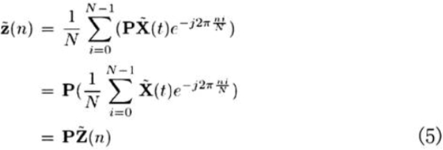
また、第2カメラにおける投影式の離散フーリエ変換は次のようになる。

式(6)は次のように書き改められる。

ここで、サンプリング開始時刻のずれkは既知であるため、ej2πnk/Nは各サンプリング時刻nにおいて定数とみなせる。ここで、
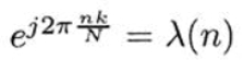
とおくと式(7)は次のように書き改めることができる。

式(5)、式(8)より通常空間におけるサンプリング時刻のずれは周波数空間において位相ずれとみなされ、λ(n)とおくことにより通常空間におけるカメラ投影の奥行きとみなすことができる。このように、通常空間における投影式に対してフーリエ変換を行うことにより周波数空間における投影式を得ることができる。
ここで重要なことは、通常空間において2台のカメラは異なる3次元点X(t)とX(t′)を投影していたが、周波数空間における投影式を考えることにより、2台のカメラが同じ3次元点Z(n)を投影していることである。
すなわち、周波数空間においては同じ点を投影していることになるため、得られた画像上の点Z(n)、Z′(n)には対応関係が存在し、3次元点Z(n)を復元することができる。したがって、後述するように、同期のとれていないカメラで3次元点が復元可能となる。
次に周波数空間における3次元復元について説明する。前述したように、周波数空間において2台の非同期カメラへの投影式は以下のように表せた。

このとき、周波数空間では2台のカメラにサンプリング時刻nにおいて、同じ3次元点Z(n)が投影されているので、得られた画像上の点Z(n)と点Z′(n)には対応関係が存在する。すなわち、通常空間においては対応が得られず復元することができなかったが、周波数空間においては復元可能となることが分かる。
そこで、次にこの復元方法について説明する。前述した通り、本発明の位置検出装置1において2台のカメラの同期はわざとずらしているためサンプリングのずれλ(n)は既知であり、カメラ行列P、P′についても求まっているものとする。
以下ではこのような条件下で周波数空間における3次元復元について詳しく述べる。式(9)および式(10)を整理すると以下のようになる。
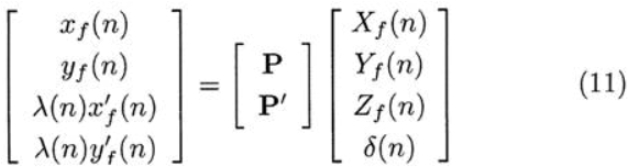
ここで、サンプリングのずれλ(n)は既知であるので式(11)の左辺は既知である。また、カメラ行列P、P′は既知なので式(11)より、3つの未知変数Xf(n)、Yf(n)、Zf(n)に対して4つの拘束を得ることができる。すなわち式(11)を解くことによりXf(n)、Yf(n)、Zf(n)を求めることができる。
ここで、式(11)を次のように置き換える。

すると、求めたい3次元点Z(n)はMの逆行列M-1を用いて最小二乗解として次のように求められる。

そして、求められたZ(n)に対し、以下のように逆フーリエ変換を行うことにより、通常空間における3次元点X(t)が求まる。ここで、

は逆フーリエ変換を表す。

また、第2カメラにおいて投影された3次元点X(t′)は、フーリエ変換により周波数空間において以下のように表せる。

つまり、第2カメラで投影された3次元点を復元するには、先に復元されたZ(n)に、

をかけてから以下のように逆フーリエ変換を行うことにより、通常空間における3次元点X(t′)が求まる。

以上のようにして同期のとれていないカメラで投影された3次元点をそれぞれ復元することができる。通常の方法では時刻t における3次元点X(t)しか復元できないが、非同期カメラを用いることで時刻t′においても3次元点X(t′)が復元できるため、より高密度に復元できる。
なお、アフィンカメラの場合には、周波数空間に変換して復元することにより、非同期のステレオカメラから2倍の密度で3次元復元を行うことができるが、これに対して射影カメラの場合には投影が非線形であるため、画像データを離散フーリエ変換したものは、離散フーリエ変換した3次元データをカメラ行列によって投影したものとは異なる。
ところが、ある条件を満たす場合には、射影カメラにおける投影は疑似的にアフィンカメラにおける投影に置き換えて考えることができ、この結果、周波数空間を介して非同期カメラから復元することが可能となる。したがって以下では、このような性質を用いることにより、非同期の射影カメラの画像から3次元復元する方法について述べる。
同期の取れた2台の射影カメラおいて3次元点Xが投影されたとすると、この投影は次式のように表せる。

ここで、λおよびλ′はそれぞれのカメラにおける射影奥行きであり、これらは2台のカメラにおいて一般に異なる。また、これら2台の射影カメラが、互いの光軸が平行でかつ2つのカメラの光学中心を結ぶ直線が画像面と平行となるように配置されているとする。以降では、このようなカメラ配置を平行ステレオと呼ぶことにする。
このような平行ステレオの場合、それぞれのカメラからみた3次元点Xの奥行き(Z座標)は互いに等しくなる。すなわち、第1カメラにおける射影奥行きλと第2カメラにおける射影奥行きλ′の間には次式の関係が成り立つ。

これは、平行ステレオにおいては、式(17)と式(18)においてPの第3行目とP′の第3行目が等しくなることからもわかる。この性質により、式(17)および式(18)は、次式のように書き直すことができる。

ここで、

(以下、「YY」とも表記する。)は次式に示す通り3次元座標

(以下、「XX」とも表記する。)を射影奥行きλで除したものである。

式(20)および式(21)より、平行ステレオにおいては、カメラ行列P、P′は射影カメラ行列でありながら、その投影はアフィンカメラと同様に線形投影モデルによって表せることがわかる。また、式(22)より、YYを求めることができれば、YYの第4行の要素でYYを除することによってXXが求まることがわかる。
すなわち、平行ステレオにおいては、式(20)および式(21)の線形投影モデルを用いてYYを推定し、求めたYYからXXを計算することによって、アフィンカメラと全く同様に線形投影モデルのもとで3次元復元を行うことができる。そこで、本実施形態ではXXの代わりにYYを求めることを考える。
2台の非同期の射影カメラがあるとすると、これらのカメラへの投影は以下のように表すことができる。

ここで、t とt′とは異なる時刻であることに注意する。これらの投影式の両辺を離散フーリエ変換することによってアフィンカメラの場合と同様に次式が得られる。

ここで、

(以下、「ZY」とも表記する。)は、

(以下、「Yt」とも表記する。またtをt′にしたものを「Yt′」とも表記する。)を離散フーリエ変換したものである。これらの式より、上記と全く同様に、ZYを復元することができる。そして、復元されたZYを逆離散フーリエ変換することにより、Ytが求まる。
また、ZYにλ(n)-1を掛けたのち逆離散フーリエ変換することにより、Yt′も求まる。このようにして求めた

において、その第4要素でそれぞれを除すれば、
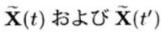
を復元することができる。以上より、平行ステレオの配置であれば、射影カメラであっても非同期のカメラから高密度な3次元復元を実現することができる。
[本実施形態による効果]
以上のように詳述した位置検出装置1において、演算部10(CPU11)は、予め設定された周期を表す基準周期で撮像された複数の撮像画像からなる第1撮像画像群、および前記第1撮像画像群の撮像タイミングに対して非同期時間だけタイミングをずらし、かつ前記基準周期で撮像された第2撮像画像群、を構成する各撮像画像中における対象物の座標を表す画像座標群をそれぞれ取得する。
[本実施形態による効果]
以上のように詳述した位置検出装置1において、演算部10(CPU11)は、予め設定された周期を表す基準周期で撮像された複数の撮像画像からなる第1撮像画像群、および前記第1撮像画像群の撮像タイミングに対して非同期時間だけタイミングをずらし、かつ前記基準周期で撮像された第2撮像画像群、を構成する各撮像画像中における対象物の座標を表す画像座標群をそれぞれ取得する。
また、演算部10は、第1撮像画像群から得られた画像座標群の時系列に沿った遷移を示す第1軌跡、および第2撮像画像群から得られた画像座標群の時系列に沿った遷移を示す第2軌跡、をそれぞれフーリエ変換することで、第1軌跡に基づく第1周波数波形、および第2軌跡に基づく第2周波数波形を演算する。そして、演算部10は、第1周波数波形と第2周波数波形とが非同期時間に応じた位相分だけずれた関係であることに基づいて、対象物の位置を演算する。
すなわち、上記の位置検出装置1では、非同期時間だけタイミングをずらして撮像された各撮像画像群中の画像座標群の軌跡をフーリエ変換することで得られる各波形が、非同期時間に応じた位相分だけずれた関係であることに基づき対象物の位置を演算する。したがって、このような位置検出装置1によれば、各撮像画像が得られた時刻における対象物の位置を検出できるので、同期した撮像画像群に基づいて対象物の位置を検出する構成と比較して、より高精度に対象物の位置を検出することができる。
また、位置検出装置1においては、対象物の位置に基づいて対象物までの距離を演算する。このような位置検出装置1によれば、対象物までの距離についても演算することができるので、対象物までの距離に応じた別の制御を実施することができる。
さらに、上記位置検出装置1においては、平行配置された複数のカメラから各撮像画像群を取得する。このような位置検出装置1によれば、射影カメラを用いる場合(アフィンカメラを用いない場合)であっても、良好に対象物の位置を検出することができる。
[実験例]
発明者らは上記効果を確認するために実験を行った。本実験では、静止した車両へ近づいていくシーンにおいて3次元復元を行った。
発明者らは上記効果を確認するために実験を行った。本実験では、静止した車両へ近づいていくシーンにおいて3次元復元を行った。
本実験例では、対象とする3次元運動の周波数成分が低い場合において、復元する周波数の上限を下げることで、従来のステレオよりも高精度に3次元復元が行えることを実画像実験により示す。
具体的には、図5に示すように、数十メートル先の車両に対して近づいていく状況下において基線長10cm以下のステレオカメラでこの車両までの距離を復元するという非常に悪条件のステレオ復元における提案法の復元精度を評価した。
図5に示す時系列画像において、車両の左右のライトをトラッキングしその座標データを得た。トラッキングにはm×mの相関トラッカーを用いた。車両のライトの画像中での大きさは距離に応じて大きく変化することから、トラッカーのサイズmはライトの大きさに応じて変化せ、テンプレートを逐次更新することにより、ライトの大きさが変わっても適切にトラッキングされるようにした。
また、トラッキングを安定化させるため、各時刻において5時刻の移動平均を取ったものを座標値とした。そして、従来法と提案法とで同じフレームレートのカメラをそれぞれ同期および非同期で撮影した場合を模擬するため、従来法においては60時刻の画像中の奇数時刻の30フレームのみを用い、提案法においては第1カメラから得られる画像には奇数時刻の30フレームを、第2カメラから得られる画像には偶数時刻の30フレームを用いた。
このようにして、従来法では30フレーム分の同期カメラの特徴点データを、また提案法では30フレーム分の非同期カメラの特徴点データをそれぞれ作成して用いた。また提案法では、離散フーリエ変換は周期関数を想定しているため、得られた直線状のデータを折り返して疑似的に周期関数とし、復元した点の前半部を復元結果とした。
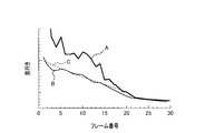
復元に用いる特徴点データは2台のカメラ間でちょうど半周期サンプリングがずれていることから、サンプリングのずれkを、k=0.5として復元を行った。本実験で用いた3次元点の距離は数mから数十mの範囲内に存在するが、図6の線Aに示すように、従来法においては復元結果が奥行き方向に大きく散乱し、正しい復元が行えていない。これは基線長10cm以下のステレオカメラという非常に厳しい条件下において復元していることから当然の結果と言える。これに対して提案法では、図6の線Bに示すように、数mから数十mの範囲内で概ね等間隔に3次元点が復元されていることから良好に復元が行えていることがわかる。なお、図6において、線Cは真値(正しい奥行き)を示す。
このように、本実施形態に係る位置検出装置1及び位置および距離検出方法によれば、非常に悪条件のステレオカメラにおいても安定した復元が行えることがわかる。
[第2実施形態]
次に、第2実施形態の位置検出装置について説明する。本実施形態(第2実施形態)では、第1実施形態の位置検出装置1と異なる箇所のみを詳述し、第1実施形態の位置検出装置1と同様の箇所については、同一の符号を付して説明を省略する。
[第2実施形態]
次に、第2実施形態の位置検出装置について説明する。本実施形態(第2実施形態)では、第1実施形態の位置検出装置1と異なる箇所のみを詳述し、第1実施形態の位置検出装置1と同様の箇所については、同一の符号を付して説明を省略する。
上記した第1実施形態では、S190の処理において、非同期カメラから得られた画像をもとに3次元復元を行う方法を示したが、本第2実施形態では、これまで述べた方法をさらに拡張することで、カメラのサンプリング周波数を超える高密度復元(高周波成分の復元)を実現する。
詳細には、カメラ画像は一般にX、Yの2次元情報を持つことから、K台のカメラによりM時刻(それぞれM撮像周期分)の画像を得た場合、これをフーリエ変換して得られる周波数領域における要素数は2KMとなり、この内で独立な周波数要素はKM個である。一方、投影元である3次元運動がN時刻分ある場合、これを表現するために必要な周波数領域における要素数は3Nであり、この内で独立な周波数要素は(3/2)N個である。
したがって、K台のカメラによりM時刻の画像を得た場合、以下の条件を満たすようなN個の周波数要素が3次元空間において復元できることがわかる。

したがって、3次元空間において復元可能な周波数成分の数Nは次式に示す通りである。

例えば、2台のカメラにより3時刻(3撮像周期分)観測した画像からは、4時刻観測した場合と同じ高周波成分を含む3次元情報が復元可能である。しかし、通常のステレオカメラでは2台のカメラによって同じ3次元点を観測しているため、画像から得られる情報には従属性があり、このような復元は行えない。これに対して非同期カメラではそれぞれのカメラが異なる3次元点を観測しているため独立な情報が得られ、式(28)に従って高周波3次元信号の復元が可能となる。
次に、高密度復元の具体的な方法について述べる。空間中の3次元点の運動X(t)が0次からN-1次までの周波数成分

より成るとすると、この3次元点の周波数空間における表現Z(n)とこれを投影したときの実空間における2次元画像

との関係は次式のように表せる。

ここで、αはスカラ変数であり投影時の射影奥行きを表す。今、K台の非同期カメラ
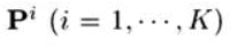
でこの3次元点を観測したとすると、それぞれのカメラへの投影は以下のように表せる。

ここで、k iは1番目のカメラに対するi番目のカメラのサンプリング遅れを表す。すなわち、k1=0である。これらK台のカメラの投影式を展開して整理すると次式に示すように3次元運動点の周波数成分

に関する線形方程式が得られる。

ここで、Mは以下に示す(2KM)×(3N +1)行列である。
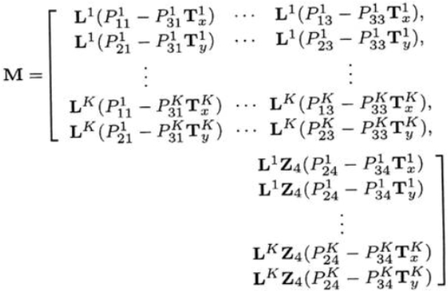
Z4はZ(n)の第4行であり、Liは次式に示すように、

よりなるM×N行列である。

また、Txi、Tyiは、次式のように第iカメラの画像におけるM時刻分のX、Y座標より成るベクトルである。

式(31)は、3次元運動の周波数成分が非同期カメラから得られた画像によって線形表現できることを表している。したがって、式(28)の不等式が成り立つ場合には、MtMの最小固有値に対応する固有ベクトルとして3次元運動点のN個の周波数成分fがM時刻の非同期画像から復元できる。ここで、Mtは、行列Mの転置行列を示す。
以上述べた通り、複数のカメラ間の同期をわざとずらして撮像し復元することにより、従来のステレオ復元では不可能であった高い周波数の3次元運動を復元することができる。
このような第2実施形態の位置検出装置においては、実空間における対象物の位置と該位置の軌跡をフーリエ変換して得られる周波数成分との関係に基づいて周波数成分を求め、該周波数成分に基づいて対象物の位置を演算する。
上記した位置検出装置によれば、より多くの周波数成分を求めることができるので、対象物の位置をより高精度に求めることができる。
[その他の実施形態]
本発明の主題は、上記の第1及び第2実施形態で示した内容に何ら限定されることはなく、本発明の技術的範囲に属する限り種々の形態を採りうる。
[その他の実施形態]
本発明の主題は、上記の第1及び第2実施形態で示した内容に何ら限定されることはなく、本発明の技術的範囲に属する限り種々の形態を採りうる。
例えば、上記実施形態において述べた位置および距離検出方法は、さらに任意の配置の射影ステレオカメラに拡張することができる。詳細には、任意の位置姿勢で配置された2台の射影カメラがあるとする。このとき、平面上での座標が既知であるような4点を描いた平板を用意し、2台のカメラの光学中心を結ぶ直線とこの平板とが平行になるように平板をカメラの前に配置して平板上の4点を撮像する。
この4点の平板上での座標とカメラ画像における座標とから平面射影変換を計算し、この平面射影変換によってカメラ画像全体を変換することによってカメラを仮想的に平面と平行な配置にすることができる。2台のカメラでそれぞれこのような画像変換を行うことによって、変換された2つの画像は平行ステレオの配置で撮像された画像となる。
このようにして仮想的に平行ステレオへの変換を行ったのち、先に述べた方法によって復元することで、一般の配置の射影ステレオカメラにおいても非同期化することで高密度復元を実現することができる。
また、以上述べた方法はそのままN台のマルチカメラに拡張することができる。ただし、射影カメラの場合には、これらN台のカメラの光学中心が同一直線上に存在することが必要である。光学中心が同一直線上に有りさえすれば、先に述べた方法により仮想的に平行化することで、全てのカメラが平行化された平行マルチカメラの状態にすることができる。その上で周波数領域を用いて復元することで、N台のカメラにより通常のN倍の高密度復元を行うことができる。
また、上記実施形態の位置検出装置及び位置および距離検出方法では、複数のカメラ(撮像部)を用いたが、円運動や往復運動等の周期運動をする1台のカメラで複数の撮像画像群を得るようにしてもよい。さらに、上記実施形態では位置検出装置1を車両に搭載する例について記述したが、車両に限らず任意の場所に配置することができる。
[実施形態の各構成と本発明の構成要素である各部との関係]
本実施形態における位置検出装置1において、演算部10が実行する処理のうち、S150の処理は本発明の画像座標群取得部に相当し、S190の処理は本発明の周波数波形演算部および位置演算部に相当する。
本実施形態における位置検出装置1において、演算部10が実行する処理のうち、S150の処理は本発明の画像座標群取得部に相当し、S190の処理は本発明の周波数波形演算部および位置演算部に相当する。
さらに、S200の処理は距離演算部に相当する。
1…位置検出装置、10…演算部、11…CPU、12…メモリ、21…撮像部、22…撮像部、23…走行状態検出部。
Claims (7)
- 複数の撮像画像に基づいて撮像画像中の対象物の位置を検出する位置検出装置であって、
予め設定された周期を表す基準周期で撮像された複数の撮像画像からなる第1撮像画像群、および前記第1撮像画像群の撮像タイミングに対して非同期時間だけタイミングをずらし、かつ前記基準周期で撮像された第2撮像画像群、を構成する各撮像画像中における対象物の座標を表す画像座標群をそれぞれ取得する画像座標群取得部と、
前記第1撮像画像群と前記第2撮像画像群とが前記非同期時間だけずれた関係であることに基づいて、前記各画像座標群から前記対象物の位置を演算する位置演算部と、を備えたことを特徴とする位置検出装置。 - 請求項1に記載の位置検出装置において、
前記第1撮像画像群から得られた画像座標群の時系列に沿った遷移を示す第1軌跡、および前記第2撮像画像群から得られた画像座標群の時系列に沿った遷移を示す第2軌跡、をそれぞれフーリエ変換することで、前記第1軌跡に基づく第1周波数波形、および前記第2軌跡に基づく第2周波数波形を演算する周波数波形演算部、を備え、
前記位置演算部は、前記第1周波数波形と前記第2周波数波形とが前記非同期時間に応じた位相分だけずれた関係であることに基づいて、前記対象物の位置を演算することを特徴とする位置検出装置。 - 請求項1に記載の位置検出装置において、前記対象物の位置に基づいて前記対象物までの距離を演算する距離演算部、を備えたことを特徴とする位置検出装置。
- 請求項1に記載の位置検出装置において、前記画像座標群取得部は、平行配置された複数の射影カメラから取得された各撮像画像群に基づく画像座標群を取得することを特徴とする位置検出装置。
- 請求項1に記載の位置検出装置において、前記位置演算部は、実空間における前記対象物の位置と該位置の軌跡をフーリエ変換して得られる周波数成分との関係に基づいて前記周波数成分を求め、該周波数成分に基づいて前記対象物の位置を演算することを特徴とする位置検出装置。
- 請求項1に記載の位置検出装置の各部の機能を実現する、メモリ内に格納された位置検出プログラムと、前記位置検出プログラムを実行するコンピュータと、からなる位置検出装置。
- 請求項1に記載の位置検出装置は、前記複数の撮像画像を撮像する複数の撮像部を備え、前記画像座標群取得部は、前記複数の撮像部が撮像し送信した前記複数の撮像画像を受信することを特徴とする位置検出装置。
Priority Applications (1)
| Application Number | Priority Date | Filing Date | Title |
|---|---|---|---|
| US14/414,347 US9626765B2 (en) | 2012-07-13 | 2013-04-25 | Position detection device detecting a position of target object and a position detection program |
Applications Claiming Priority (2)
| Application Number | Priority Date | Filing Date | Title |
|---|---|---|---|
| JP2012157972A JP6022834B2 (ja) | 2012-07-13 | 2012-07-13 | 位置検出装置、および位置検出プログラム |
| JP2012-157972 | 2012-07-13 |
Publications (1)
| Publication Number | Publication Date |
|---|---|
| WO2014010293A1 true WO2014010293A1 (ja) | 2014-01-16 |
Family
ID=49915768
Family Applications (1)
| Application Number | Title | Priority Date | Filing Date |
|---|---|---|---|
| PCT/JP2013/062224 Ceased WO2014010293A1 (ja) | 2012-07-13 | 2013-04-25 | 位置検出装置、および位置検出プログラム |
Country Status (3)
| Country | Link |
|---|---|
| US (1) | US9626765B2 (ja) |
| JP (1) | JP6022834B2 (ja) |
| WO (1) | WO2014010293A1 (ja) |
Cited By (1)
| Publication number | Priority date | Publication date | Assignee | Title |
|---|---|---|---|---|
| WO2022209151A1 (ja) * | 2021-03-30 | 2022-10-06 | 株式会社デンソーウェーブ | 三次元計測装置 |
Families Citing this family (7)
| Publication number | Priority date | Publication date | Assignee | Title |
|---|---|---|---|---|
| JP6009502B2 (ja) * | 2014-07-29 | 2016-10-19 | 株式会社ソニー・インタラクティブエンタテインメント | 情報処理装置および情報処理方法 |
| JP6212021B2 (ja) * | 2014-11-26 | 2017-10-11 | 株式会社Soken | 距離検出装置 |
| KR101973460B1 (ko) * | 2015-02-09 | 2019-05-02 | 한국전자통신연구원 | 다중 입력 영상 보정 장치 및 방법 |
| EP3360023A4 (en) * | 2015-10-09 | 2018-10-10 | SZ DJI Technology Co., Ltd. | Salient feature based vehicle positioning |
| CN108596735A (zh) * | 2018-04-28 | 2018-09-28 | 北京旷视科技有限公司 | 信息推送方法、装置及系统 |
| CN115086541B (zh) * | 2021-03-15 | 2023-12-22 | 北京字跳网络技术有限公司 | 一种拍摄位置确定方法、装置、设备及介质 |
| US12394082B2 (en) * | 2022-08-16 | 2025-08-19 | Verizon Patent And Licensing Inc. | Methods and systems for resolving 3D positions of multiple objects present within a 3D space |
Citations (3)
| Publication number | Priority date | Publication date | Assignee | Title |
|---|---|---|---|---|
| JP2005100278A (ja) * | 2003-09-26 | 2005-04-14 | Chube Univ | 3次元位置計測システムおよび3次元位置計測方法 |
| JP2006047252A (ja) * | 2004-08-09 | 2006-02-16 | Fuji Heavy Ind Ltd | 画像処理装置 |
| JP2006170993A (ja) * | 2004-12-10 | 2006-06-29 | Microsoft Corp | 非同期画像部分をマッチングすること |
Family Cites Families (4)
| Publication number | Priority date | Publication date | Assignee | Title |
|---|---|---|---|---|
| JP3925488B2 (ja) * | 2003-11-11 | 2007-06-06 | 日産自動車株式会社 | 車両用画像処理装置 |
| US7697749B2 (en) | 2004-08-09 | 2010-04-13 | Fuji Jukogyo Kabushiki Kaisha | Stereo image processing device |
| US8335345B2 (en) * | 2007-03-05 | 2012-12-18 | Sportvision, Inc. | Tracking an object with multiple asynchronous cameras |
| IL207116A (en) * | 2009-08-10 | 2014-12-31 | Stats Llc | Location tracking method and method |
-
2012
- 2012-07-13 JP JP2012157972A patent/JP6022834B2/ja not_active Expired - Fee Related
-
2013
- 2013-04-25 US US14/414,347 patent/US9626765B2/en not_active Expired - Fee Related
- 2013-04-25 WO PCT/JP2013/062224 patent/WO2014010293A1/ja not_active Ceased
Patent Citations (3)
| Publication number | Priority date | Publication date | Assignee | Title |
|---|---|---|---|---|
| JP2005100278A (ja) * | 2003-09-26 | 2005-04-14 | Chube Univ | 3次元位置計測システムおよび3次元位置計測方法 |
| JP2006047252A (ja) * | 2004-08-09 | 2006-02-16 | Fuji Heavy Ind Ltd | 画像処理装置 |
| JP2006170993A (ja) * | 2004-12-10 | 2006-06-29 | Microsoft Corp | 非同期画像部分をマッチングすること |
Non-Patent Citations (3)
| Title |
|---|
| MATSUMOTO H. ET AL.: "Multiview Constraints in Frequency Space and Camera Calibration from Unsynchronized Images", 2010 IEEE CONFERENCE ON COMPUTER VISION AND PATTERN RECOGNITION(CVPR), 2010, pages 1601 - 1608 * |
| SHOICHI SHIMIZU ET AL.: "Pseudo Stereo Method for Measuring 3D Position Using Three Cameras", THE JAPANESE SOCIETY FOR ARTIFICIAL INTELLIGENCE DAI 19 KAI SIG-CHALLENGE KENKYUKAI, 2 May 2004 (2004-05-02), pages 6 - 11 * |
| TOMOMI KAGAMI ET AL.: "Hidoki Multi-Camera ni yoru Komitsudo Sanjigen Fukugen", MEETING ON IMAGE RECOGNITION AND UNDERSTANDING (MIRU2012), August 2012 (2012-08-01) * |
Cited By (4)
| Publication number | Priority date | Publication date | Assignee | Title |
|---|---|---|---|---|
| WO2022209151A1 (ja) * | 2021-03-30 | 2022-10-06 | 株式会社デンソーウェーブ | 三次元計測装置 |
| JPWO2022209151A1 (ja) * | 2021-03-30 | 2022-10-06 | ||
| CN116964409A (zh) * | 2021-03-30 | 2023-10-27 | 电装波动株式会社 | 三维测量装置 |
| JP7401024B2 (ja) | 2021-03-30 | 2023-12-19 | 株式会社デンソーウェーブ | 三次元計測装置 |
Also Published As
| Publication number | Publication date |
|---|---|
| US20150199817A1 (en) | 2015-07-16 |
| US9626765B2 (en) | 2017-04-18 |
| JP2014020845A (ja) | 2014-02-03 |
| JP6022834B2 (ja) | 2016-11-09 |
Similar Documents
| Publication | Publication Date | Title |
|---|---|---|
| JP6022834B2 (ja) | 位置検出装置、および位置検出プログラム | |
| US9177389B2 (en) | Motion vector generation apparatus and motion vector generation method | |
| CN108734776B (zh) | 一种基于散斑的三维人脸重建方法及设备 | |
| CN101608908B (zh) | 数字散斑投影和相位测量轮廓术相结合的三维数字成像方法 | |
| US10853960B2 (en) | Stereo matching method and apparatus | |
| JP2019194616A (ja) | 画像に基づく位置検出方法、装置、機器及び記憶媒体 | |
| JP2011530071A5 (ja) | ||
| CN110009672A (zh) | 提升ToF深度图像处理方法、3D图像成像方法及电子设备 | |
| KR20130084849A (ko) | 카메라 추적을 위한 방법 및 장치 | |
| KR20120048370A (ko) | 물체 자세 인식장치 및 이를 이용한 물체 자세 인식방법 | |
| KR101592405B1 (ko) | 3차원 영상 획득 방법, 장치 및 컴퓨터 판독 가능한 기록 매체 | |
| CN113551617A (zh) | 基于条纹投影的双目双频互补三维面型测量方法 | |
| JP4941565B2 (ja) | 対応点探索装置および対応点探索方法 | |
| CN111815697B (zh) | 一种热变形动态三维测量方法 | |
| JP6052186B2 (ja) | 画像処理装置 | |
| CN108596008A (zh) | 针对三维人脸测量的面部抖动补偿方法 | |
| WO2019058487A1 (ja) | 3次元復元画像処理装置、3次元復元画像処理方法及び3次元復元画像処理プログラムを記憶したコンピュータ読み取り可能な記憶媒体 | |
| KR20120047482A (ko) | 평면 영역을 이용한 이종 카메라간 교정 방법 및 장치 | |
| Kumar et al. | Dual tree fractional quaternion wavelet transform for disparity estimation | |
| Garro et al. | Fast Metric Acquisition with Mobile Devices. | |
| JP2025059141A (ja) | 推定装置、および、推定方法 | |
| Dobias et al. | Real-time global prediction for temporally stable stereo | |
| WO2013173383A1 (en) | Methods and apparatus for processing image streams | |
| CN119516120B (zh) | 一种三维重建与语义分割及深度估计联合处理方法与设备 | |
| Kakumu et al. | High Frequency 3D Reconstruction from Unsynchronized Multiple Cameras. |
Legal Events
| Date | Code | Title | Description |
|---|---|---|---|
| 121 | Ep: the epo has been informed by wipo that ep was designated in this application |
Ref document number: 13816540 Country of ref document: EP Kind code of ref document: A1 |
|
| WWE | Wipo information: entry into national phase |
Ref document number: 14414347 Country of ref document: US |
|
| NENP | Non-entry into the national phase |
Ref country code: DE |
|
| 122 | Ep: pct application non-entry in european phase |
Ref document number: 13816540 Country of ref document: EP Kind code of ref document: A1 |