WO2014010080A1 - 太陽電池モジュールおよび太陽光発電装置 - Google Patents
太陽電池モジュールおよび太陽光発電装置 Download PDFInfo
- Publication number
- WO2014010080A1 WO2014010080A1 PCT/JP2012/067939 JP2012067939W WO2014010080A1 WO 2014010080 A1 WO2014010080 A1 WO 2014010080A1 JP 2012067939 W JP2012067939 W JP 2012067939W WO 2014010080 A1 WO2014010080 A1 WO 2014010080A1
- Authority
- WO
- WIPO (PCT)
- Prior art keywords
- light guide
- light
- main surface
- solar cell
- cell module
- Prior art date
- Legal status (The legal status is an assumption and is not a legal conclusion. Google has not performed a legal analysis and makes no representation as to the accuracy of the status listed.)
- Ceased
Links
Images








Classifications
-
- H—ELECTRICITY
- H10—SEMICONDUCTOR DEVICES; ELECTRIC SOLID-STATE DEVICES NOT OTHERWISE PROVIDED FOR
- H10F—INORGANIC SEMICONDUCTOR DEVICES SENSITIVE TO INFRARED RADIATION, LIGHT, ELECTROMAGNETIC RADIATION OF SHORTER WAVELENGTH OR CORPUSCULAR RADIATION
- H10F77/00—Constructional details of devices covered by this subclass
- H10F77/40—Optical elements or arrangements
- H10F77/42—Optical elements or arrangements directly associated or integrated with photovoltaic cells, e.g. light-reflecting means or light-concentrating means
- H10F77/488—Reflecting light-concentrating means, e.g. parabolic mirrors or concentrators using total internal reflection
-
- Y—GENERAL TAGGING OF NEW TECHNOLOGICAL DEVELOPMENTS; GENERAL TAGGING OF CROSS-SECTIONAL TECHNOLOGIES SPANNING OVER SEVERAL SECTIONS OF THE IPC; TECHNICAL SUBJECTS COVERED BY FORMER USPC CROSS-REFERENCE ART COLLECTIONS [XRACs] AND DIGESTS
- Y02—TECHNOLOGIES OR APPLICATIONS FOR MITIGATION OR ADAPTATION AGAINST CLIMATE CHANGE
- Y02E—REDUCTION OF GREENHOUSE GAS [GHG] EMISSIONS, RELATED TO ENERGY GENERATION, TRANSMISSION OR DISTRIBUTION
- Y02E10/00—Energy generation through renewable energy sources
- Y02E10/50—Photovoltaic [PV] energy
- Y02E10/52—PV systems with concentrators
Definitions
- the present invention relates to a solar cell module and a solar power generation device.
- Conventional solar power generation apparatuses generally have a form in which a plurality of solar cell panels are spread over the entire surface facing the sun.
- a solar power generation apparatus in which a gantry is installed on the roof of a building and a plurality of solar battery panels are spread on the gantry is known.
- a solar cell panel is made of an opaque semiconductor and cannot be stacked. Therefore, in a solar power generation device, a large-area solar cell panel is required to ensure the amount of power.
- the device there is a restriction that the device must be installed in a limited place such as a roof, and there is a limit to the amount of power that can be obtained.
- Patent Document 1 a solar cell provided with a light guide member for guiding incident sunlight to the solar cell has been proposed (see Patent Document 1 below).
- the solar cell described in Patent Document 1 includes a light guide member having a plurality of V-shaped grooves and having a substantially right-sided side shape, and the solar cell is attached to an end surface of the light guide member.
- the present invention has been made to solve the above-described problems, and an object of the present invention is to provide a solar cell module and a solar power generation device that can suppress a decrease in power generation efficiency.
- a solar cell module includes a light guide unit having a first light guide and a second light guide, and the light guide unit.
- a solar cell element that receives light emitted from the first light guide, wherein the first light guide is in contact with the first main surface, the second main surface, the first main surface, and the second main surface.
- the light from the outside is incident from the first main surface, propagated through the first main surface and emitted from the first end surface, and the second light guide has a first main surface and a second main surface.
- the second light guide has a first main surface and a second main surface.
- the first main surface of the second light guide is opposed to the solar cell element, and the solar cell element receives the light emitted from the first end surface of the first light guide, and the second light guide second.
- the thickness of the first light guide formed is gradually increased from the distance from the first end face of the first light guide to the first end face of the first light guide.
- the first light guide and the second light guide are in direct contact, or the refractive index of the first light guide and the second You may adhere
- the first main surface of the first light guide is reflected by the reflection surface of the second light guide and is incident on the first light guide. It may function as a reflecting surface that reflects the reflected light and changes the traveling direction of the light.
- the first main surface of the second light guide and the second main surface of the second light guide may be parallel to each other.
- a plurality of grooves are formed on the second main surface of the second light guide, and the grooves are formed on the second light guide.
- An inclined surface that is inclined so as to form a predetermined inclination angle with respect to the second main surface may be provided, and the inclined surface may function as a reflecting surface of the second light guide.
- the first main surface of the first light guide may be a flat surface.
- the second main surface of the first light guide is a flat surface
- the first main surface of the second light guide is the first It may be a flat surface parallel to the second main surface of one light guide.
- each of the light guide units is a first main surface of the first light guide.
- the second main surface of the second light guide may be laminated to face each other.
- the light guide units may be arranged such that the first end surfaces of the first light guides face in the same direction. .
- each of the light guide units has a thickness of the first light guide from the far end of the first end face of the first light guide.
- the first light guides may be gradually thicker as they approach the first end face, and the first end faces of the first light guides may face each other in opposite directions.
- a third light guide is provided on a light incident side of the light guide unit, and the third light guide has a first main surface. And a second main surface, the first main surface, and a first end surface in contact with the second main surface. Light from outside is incident on the first main surface and propagates through the first main surface.
- the light guide unit is emitted from an end surface, and the light guide unit transmits light transmitted through the third light guide from the first main surface of the first light guide and propagates through the first light guide unit.
- the first light guide is emitted from one end face, and the first main surface of the third light guide is reflected by the second main surface of the second light guide and passes through the first light guide, and the third light guide Functioning as a reflecting surface that reflects the light incident on the light source and changes the traveling direction of the light, and the thickness of the third light guide is determined from the first end surface of the third light guide. It may be gradually thicker toward the first end surface 3 the light guide.
- the solar cell module includes a light condensing member that condenses light emitted from the first end face of the first light guide and enters the solar cell element. Also good.
- the materials of both the first light guide and the second light guide constituting the light guide unit are for wavelengths of 400 nm or less. It may have transparency.
- the solar power generation device receives a light guide unit having a first light guide and a second light guide, and light emitted from the light guide unit.
- a solar cell element, and the first light guide has a first main surface, a second main surface, a first end surface in contact with the first main surface, and the second main surface.
- Light is incident from the first main surface, propagated inside and emitted from the first end surface, the second light guide has a first main surface and a second main surface, and the first The first light guide and the second light guide have a refractive index lower than that of the light guide, and the first light guide and the second light guide have a second main surface of the first light guide and the second light guide.
- the solar cell element receives light emitted from the first end surface of the first light guide, and the first main surface is opposed to the second main surface of the second light guide. From the first main surface of the light guide A reflective surface is formed that reflects the light that is transmitted through the first light guide and reflects the light incident on the second light guide to change the traveling direction of the light, and the thickness of the first light guide is The solar cell module gradually increases in thickness as it approaches the first end face of the first light guide from a distance from the first end face of the first light guide.
- the present invention it is possible to provide a solar cell module and a solar power generation device that can suppress a decrease in power generation efficiency.
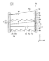
- FIG. 1 It is a perspective view which shows the solar cell module of the 1st Embodiment of this invention. It is sectional drawing of a light guide unit same as the above. It is a fragmentary sectional view of the 2nd light guide same as the above. It is a figure which shows the transmittance
- FIG. 1 is a perspective view showing a solar cell module 1 according to a first embodiment of the present invention.
- the solar cell module 1 condenses the light emitted from the light guide unit 2 and the light guide unit 2 having the first light guide 3 and the second light guide 5 that are arranged to face each other.
- the first light guide 3 includes a first main surface 3a that is a light incident surface, a second main surface 3b that faces the first main surface 3a, and a first end surface 3c that is a light emission surface.
- the second light guide 5 includes a first main surface 5a that is a light incident surface, a second main surface 5b that faces the first main surface 5a, and a first end surface 5c that is a light emission surface.
- the first light guide 3 and the second light guide 5 are the first light guide 3 with the second main surface 3b of the first light guide 3 and the first main surface 5a of the second light guide 5 facing each other.
- the adhesive member 4 having a refractive index between the refractive index of the light guide 3 and the refractive index of the second light guide 5 is sandwiched.
- the first light guide 3 and the second light guide 5 are in a state where the second main surface 3b of the first light guide 3 and the first main surface 5a of the second light guide 5 face each other. It may be in direct contact. Moreover, the 1st light guide 3 and the 2nd light guide 5 may be fixed through the air layer, and may be indirectly fixed through the plate-shaped member.
- the first main surface 3a of the first light guide 3 and the first main surface 5a of the second light guide 5 face the same direction (light incident side: + Z direction).
- the first light guide 3 on the front stage side (the side closer to the side on which the light L is incident) can be captured.
- the light that has not been reflected can be reflected by the reflective surface formed on the second main surface 5b of the second light guide 5 on the rear stage side (the side far from the side on which the light L is incident) and taken in by the solar cell element 7. Become.
- the first end surface 3c of the first light guide 3 and the first end surface 5c of the second light guide 5 are oriented in the same direction.
- the first end face 3c of the first light guide 3 and the first end face 5c of the second light guide 5 are arranged on the same plane parallel to the XZ plane, and the first end face 3c of the first light guide 3 is arranged.
- the light emitted from the first light guide 5 and the light emitted from the first end face 5 c of the second light guide 5 can be condensed by the common light collecting member 6.
- the first light guide 3 is a trapezoidal member having a first main surface 3a and a second main surface 3b.
- the thickness of the first light guide 3 gradually increases from the distance from the first end surface 3c of the first light guide 3 toward the first end surface 3c of the first light guide 3.
- the thickness of the first light guide 3 is the first main surface 3a of the first light guide 3 when viewed from a direction orthogonal to the second main surface 3b of the first light guide 3. This is the distance between the first light guide 3 and the second main surface 3b.
- the first main surface 3 a of the first light guide 3 is viewed from the direction orthogonal to the second main surface 3 b of the first light guide 3.
- the second main surface 3b of the first light guide 3 gradually increase as the distance from the first end surface 3c of the first light guide 3 approaches the first end surface 3c of the first light guide 3. It is inclined to become.
- the first main surface 3a and the second main surface 3b of the first light guide 3 are flat surfaces.
- the organic material or inorganic material with high transparency such as an acrylic resin, polycarbonate resin, glass, is used, for example.
- the 1st light guide 3 shall be formed with the material which disperse
- PMMA polymethyl methacrylate resin
- the average particle diameter of the zirconia particles is about 20 nm, which is sufficiently smaller than the wavelength of light.
- the refractive index n1 of the first light guide 3 is 1.8.
- the refractive index (1.8) of the first light guide 3 can be obtained by dispersing zirconia particles in a PMMA resin at a component ratio of 1: 1.
- the bonding member 4 is a member that bonds the second main surface 3 b of the first light guide 3 and the first main surface 5 a of the second light guide 5.
- the adhesive member 4 for example, an acrylic UV curable resin is used.
- the thickness of the adhesive member 4 (the distance between the second main surface 3b of the first light guide 3 and the first main surface 5a of the second light guide 5) is about 2 ⁇ m, and the refractive index of the adhesive member 4 is 1. 5.
- the second light guide 5 is a plate-like member having a first main surface 5a and a second main surface 5b perpendicular to the Z axis (parallel to the XY plane).
- the first main surface 5 a of the second light guide 5 is a flat surface parallel to the second main surface 3 b of the first light guide 3.
- the light enters the first main surface 3 a of the first light guide 3, passes through the first light guide 3, and enters the second light guide 5.
- a reflection surface (slowly inclined surface T2) that reflects light and changes the traveling direction of the light is formed.
- the organic material or inorganic material with high transparency such as an acrylic resin, polycarbonate resin, glass, is used, for example.
- the second main surface 5b of the second light guide 5 is provided with a plurality of grooves T extending in the X direction.
- the groove T has a V-shaped shape having a steeply inclined surface T1 inclined at a large angle with respect to a surface parallel to the XY plane and a gently inclined surface T2 inclined at a small angle with respect to a surface parallel to the XY plane. It is a groove.
- FIG. 1 only a few grooves T are shown in order to simplify the drawing, but in practice, a large number of fine grooves T having a width of about 100 ⁇ m are formed.
- the groove T is formed, for example, by injection molding a resin (for example, PMMA) using a mold.
- channel T can also be formed by cutting the 2nd main surface 5b of the 2nd light guide 5 originally flat.
- the refractive index n2 of the second light guide 5 is 1.3.
- the refractive index (1.3) of the second light guide 5 can be obtained by dispersing hollow PMMA particles in a predetermined ratio in PMMA resin.
- the second main surface 5b of the second light guide 5 is provided with a plurality of such grooves T in the Y direction so that the steeply inclined surface T1 and the gently inclined surface T2 are in contact with each other.
- the shapes and sizes of the plurality of grooves T provided on the second main surface 5b are all the same.
- FIG. 4 is a diagram showing the transmittance characteristics of the light guide unit 2.
- the horizontal axis represents the wavelength of light
- the vertical axis represents the transmittance of the light guide unit 2.
- the light guide when “XY-0159” manufactured by Mitsubishi Rayon Co., Ltd. is used as the material of both the first light guide 3 and the second light guide 5 constituting the light guide unit 2.
- the transmittance characteristics of unit 2 are shown.
- the materials of both the first light guide 3 and the second light guide 5 constituting the light guide unit 2 have transparency to wavelengths of 400 nm or more so that external light can be effectively taken in. It is desirable to have transparency even for wavelengths of 400 nm or less.
- a material having a transmittance of 90% or more, more preferably 93% or more with respect to light in a wavelength region of 360 nm to 800 nm is suitable.
- “Acrylite” registered trademark
- Mitsubishi Rayon Co., Ltd. that does not contain a UV absorber is high in light over a wide wavelength region. Since it has transparency, it is preferable.
- the light collecting member 6 is configured to make the intensity distribution of the light emitted from the first end surface 3 c of the first light guide 3 and the first end surface 5 c of the second light guide 5 uniform, and to form a solar cell.
- This is an integrator optical element (homogenizer) that is emitted to the element 7.
- the condensing member 6 is a light incident surface 6a facing the first end surface 3c of the first light guide 3 and the first end surface 5c of the second light guide 5, and light that emits light incident from the light incident surface 6a.
- An exit surface 6b and a reflecting surface 6c that reflects the light incident from the light incident surface 6a and propagates it to the light exit surface 6b are provided.
- the condensing member 6 has, for example, a quadrangular frustum shape having the light incident surface 6a as a bottom surface, the light exit surface 6b as a top surface, and the reflecting surface 6c as a side surface.
- the condensing member 6 is formed, for example, by injection molding a resin such as PMMA.
- the reflection surface 6c reflects light by total reflection.
- a reflection layer made of a metal film or a dielectric multilayer film may be formed on the reflection surface 6c, and the reflection layer 6c may reflect light. .
- the solar cell element 7 is disposed with the light receiving surface facing the light exit surface 6 b of the light collecting member 6. As the light from the light guide unit 2 that has entered the light incident surface 6 a of the light collecting member 6 is repeatedly reflected by the reflecting surface 6 c of the light collecting member 6, the illuminance distribution is made uniform. Then, the light with uniform illuminance distribution is incident on the solar cell element 7.
- the power generation efficiency of the solar cell element 7 can be increased by making the illuminance distribution of the light incident on the solar cell element 7 uniform.
- the solar cell element 7 a known solar cell such as a silicon solar cell, a compound solar cell, or an organic solar cell can be used.
- a compound solar cell using a GaAs compound semiconductor is suitable as the solar cell element 7 because it can generate power with high efficiency.
- the compound solar cell is generally expensive, the light L can be condensed by the light guide unit 2 and the condensing member 6, so that the area of the solar cell element 7 can be kept small. Therefore, an increase in member cost can be suppressed.
- the frame body 8 includes a transmission surface 8 a that transmits the light L on a surface facing the first main surface 3 a of the first light guide 3.
- the transmission surface 8a may be an opening of the frame 8 or a transparent member such as glass fitted in the opening of the frame 8.
- the first main surface 3 a of the first light guide 3 that overlaps the transmission surface 8 a of the frame 8 when viewed from the Z direction is the light incident surface of the light guide unit 2.
- the first end surface 3 c of the first light guide 3 and the first end surface 5 c of the second light guide 5 are the first light exit surfaces of the light guide unit 2.
- FIG. 2 is a cross-sectional view of the light guide unit 2 of the present embodiment.
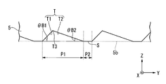
- FIG. 3 is a partial cross-sectional view of the second light guide 5 of the present embodiment.
- illustration of the adhesive member 4 is omitted for convenience.
- the first light guide 3 is a trapezoidal member having a first main surface 3a having an angle ⁇ A with respect to the Y axis.
- the angle ⁇ A is set so as to satisfy the relationship ⁇ A ⁇ 45 °, for example, taking into account the sun's daily movement.
- the dimensions of the first light guide 3 are, for example, 100 mm ⁇ 100 mm in the vertical and horizontal dimensions (the x-axis direction and the y-axis direction in FIG. 2) of the rectangle that forms the second main surface 3b, and the smaller thickness.
- the thickness dA1 (dimension in the z-axis direction in FIG. 2) is 1 mm
- the thicker thickness dA2 dimension in the z-axis direction in FIG. 2) is 8 mm
- the angle ⁇ A is 5 °.
- the vertical and horizontal dimensions, the smaller thickness dA1, the thicker thickness dA2, and the angle ⁇ A are not limited thereto.
- the second light guide 5 is a plate-like member having a first main surface 5a and a second main surface 5b that are parallel to each other.
- the second main surface 5b of the second light guide 5 is provided with a plurality of grooves T that reflect the light incident from the first main surface 5a and change the traveling direction of the light to the direction toward the first end surface 5c.
- the groove T is a V-shaped groove in which a steeply inclined surface T1 that forms an angle ⁇ B1 with respect to the Y axis and a gently inclined surface T2 that forms an angle ⁇ B2 with respect to the Y axis intersect at a ridgeline T3.
- the angle ⁇ B1 and the angle ⁇ B2 satisfy the relationship ⁇ B1> ⁇ B2.
- a gently inclined surface T2 is disposed on the first end surface 5c side with the ridge line T3 interposed therebetween, and a steeply inclined surface T1 is disposed on the opposite side to the first end surface 5c.
- a flat portion S is provided between two adjacent grooves T.
- the light reflected by the gently inclined surface T2 becomes difficult to enter the steeply inclined surface T1 of the adjacent groove T. That is, the light propagating through the second light guide 5 is affected by the steeply inclined surface T1, and the incident angle of the light with respect to the first main surface 5a or the second main surface 5b is reduced, and the waveguide conditions are lost. , Light is prevented from leaking to the outside.
- the second light guide 5 has dimensions of 100 mm ⁇ 100 mm in the length and breadth (the x-axis direction and the y-axis direction in FIG. 2) of the rectangle that forms the first main surface 5a.
- the thickness dB (dimension in the z-axis direction in FIG. 2) is 1 mm
- the angle ⁇ B1 is 45 °
- the angle ⁇ B2 is 15 °
- the width P1 in the Y direction of one groove T is 100 ⁇ m.
- the width P2 in the Y direction of the flat portion S between the two grooves T is 50 ⁇ m.
- the vertical and horizontal dimensions, the thickness dB, the angle ⁇ B1, the angle ⁇ B2, the width P1 of the groove T in the Y direction, and the width P2 of the flat portion S in the Y direction are not limited thereto.
- the gently inclined surface T ⁇ b> 2 totally reflects light L (for example, sunlight) incident from the first main surface 5 a and changes the traveling direction of the light to the first end surface 3 c of the first light guide 3. It functions as a reflective surface that changes in the direction it heads.
- the light L incident obliquely with respect to the first main surface 5a is reflected by the gently inclined surface T2 and propagates through the second light guide 5 in the Y direction.
- the steeply inclined surface T1 transmits the light L incident obliquely with respect to the first main surface 5a, and the light L is emitted from the second main surface 5b.
- the light L incident at a small angle with respect to the plane parallel to the XY plane propagates only in the first light guide 3 and enters the first end face 3c without entering the second light guide 5.
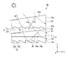
- FIG. 5 is a diagram for explaining the action of the reflecting surface in the light guide unit 2 of the present embodiment.
- symbol L ⁇ b> 1 is light incident at a relatively large incident angle ⁇ ⁇ b> 1 a with respect to the first main surface 3 a of the first light guide 3
- symbol L ⁇ b> 2 is on the first main surface 3 a of the first light guide 3.
- light incident at a relatively small incident angle ⁇ 2a is shown.
- illustration of the adhesive member 4 is omitted for convenience.
- the sunlight L2 is incident on the first main surface 3a of the first light guide 3 at the incident angle ⁇ 2a, the sunlight L2 is refracted at the refraction angle ⁇ 2b on the first main surface 3a and the first guide Incident into the light body 3.
- the light incident on the gently inclined surface T2 at the incident angle ⁇ 2e is totally reflected at the reflection angle ⁇ 2e with respect to the gently inclined surface T2, and propagates in the second light guide 5 toward the first end surface 3c.
- Light incident on the first main surface 5a of the second light guide 5 (the interface between the second light guide 5 and an adhesive member not shown) at an incident angle ⁇ 2f is refracted at the refraction angle ⁇ 2g at the interface.
- the light enters the first light guide 3.
- the light incident on the first main surface 3a of the first light guide 3 at an incident angle ⁇ 2h is totally reflected at the reflection angle ⁇ 2h with respect to the first main surface 3a and propagates through the first light guide 3.
- the first main surface 3a of the first light guide 3 reflects the light incident on the first light guide 3 after being reflected by the reflecting surface (slowly inclined surface T2) of the second light guide 5 to reflect the light. It functions as a reflecting surface that changes the traveling direction.
- Light incident on the second main surface 3b (interface between the first light guide 3 and an adhesive member not shown) of the first light guide 3 at an incident angle ⁇ 2i is reflected on the second main surface 3b. The light is totally reflected at the angle ⁇ 2i and propagates in the first light guide 3 toward the first end face 3c.
- the angle ⁇ A of the first light guide 3 is 21 degrees
- the refractive index n1 of the first light guide 3 is 1.8
- the gentle inclination angle ⁇ B2 of the second light guide 5 is 15 degrees.
- the refractive index n2 of the second light guide 5 is 1.3
- the refractive index n0 of the external air is 1.0.
- the refractive index of an adhesive member (not shown) is not considered.
- the critical angle at the interface between the first light guide 3 and the second light guide 5 is 51 degrees.
- the incident angle ⁇ 1a of the sunlight L1 on the first main surface 3a of the first light guide 3 is 70 degrees or more, the refraction when the sunlight L1 enters the first light guide 3 will be described.
- the angle ⁇ 1b is 31 degrees or more.
- L1 is totally reflected by the second main surface 3b of the first light guide 3.
- the light totally reflected by the second main surface 3b propagates in the first light guide 3 toward the first end surface 3c.
- the critical angle at the interface between the gently inclined surface T2 of the second light guide 5 and the external air is 56 degrees, and the critical angle at the interface between the first main surface 3a of the first light guide 3 and the external air. Is 37 degrees.
- the incident angle ⁇ 2a of the sunlight L2 on the first main surface 3a of the first light guide 3 is 15 degrees or more and less than 31 degrees, the sunlight L2 enters the first light guide 3.
- the refraction angle ⁇ 2b at that time is 8 degrees or more and less than 17 degrees.
- the light L2 passes through the second main surface 3b of the first light guide 3.
- the incident angle ⁇ 2c of light on the second main surface 3b of the first light guide 3 is not less than 29 degrees and less than 38 degrees
- the refraction angle ⁇ 2d when the light L2 enters the second light guide 5 is It is 45 degrees or more and less than 57 degrees.
- the light L2 is totally reflected by the gently inclined surface T2 of the second light guide 5.
- the refraction angle ⁇ 2g when the light enters the first light guide 3 is 43 degrees or more and less than 46 degrees.
- the reflection angle ⁇ 2h on the first main surface 3a of the first light guide 3 is 64 degrees or more and less than 67 degrees
- the incident angle ⁇ 2i is equal to or greater than the critical angle ( ⁇ 2i ⁇ 51 degrees)
- the light L2 is totally reflected by the second main surface 3b of the first light guide 3.
- the light totally reflected by the second main surface 3b propagates in the first light guide 3 toward the first end surface 3c.
- the reflection surface of the first light guide 3 is the second reflection surface of the first light guide 3 and the reflection surface when viewed from a direction orthogonal to the second main surface 3 b of the first light guide 3.
- the main surface 3b is inclined so as to gradually increase as it approaches the first end surface 3c. Therefore, the incident angle ⁇ 1c when entering the second main surface 3b of the first light guide 3 is larger than the refraction angle ⁇ 1b when entering the first light guide 3. Therefore, the light incident on the first light guide 3 satisfies the total reflection condition on the second main surface 3b of the first light guide 3, and is reflected toward the first end surface 3c of the first light guide 3. It becomes easy.
- the refractive index n2 of the second light guide 5 is smaller than the refractive index n1 of the first light guide 3 (n1> n2). Therefore, the refraction angle ⁇ 2d when entering the second light guide 5 is larger than the incident angle ⁇ 2c when entering the second main surface 3b of the first light guide 3. Therefore, the light that has entered the second light guide 5 satisfies the total reflection condition at the gently inclined surface T2 of the second light guide 5, and is easily reflected toward the first end surface 3c of the first light guide 3. Become. If the refractive index n2 of the second light guide 5 is larger than the refractive index n1 of the first light guide 3, the light incident on the second light guide 5 is gently inclined by the second light guide 5. The surface T2 does not satisfy the total reflection condition, and easily passes through the second light guide 5 and leaks to the outside.
- the light incident on the second light guide 5 is totally reflected on the gently inclined surface T2 of the second light guide 5 to propagate through the second light guide 5 (an angle parallel to the XY plane and light).
- the angle formed by the propagation direction of the light becomes shallow. Therefore, the refraction angle ⁇ 2g when the light totally reflected by the gently inclined surface T2 of the second light guide 5 enters the first light guide 3 is such that the light is first reflected by the second main light of the first light guide 3. It becomes larger than the incident angle ⁇ 2c when entering the surface 3b. Therefore, the light incident on the first light guide 3 satisfies the total reflection condition on the first main surface 3a of the first light guide 3, and is reflected toward the first end surface 3c of the first light guide 3. It becomes easy.
- the light incident on the first light guide 3 is totally reflected on the first main surface 3a of the first light guide 3 to propagate through the first light guide 3 (an angle parallel to the XY plane)
- the angle formed by the light propagation direction becomes shallow. Therefore, the incident angle ⁇ 2i when the light totally reflected by the first main surface 3a of the first light guide 3 is incident on the second main surface 3b of the first light guide 3 is initially set to the first light guide 3.
- the incident light becomes larger than the incident angle ⁇ 2c when the light incident on the second main surface 3b of the first light guide 3 enters.
- the light totally reflected by the first main surface 3a of the first light guide 3 satisfies the total reflection condition by the second main surface 3b of the first light guide 3, and the first end surface of the first light guide 3 It becomes easy to be reflected toward 3c.
- the light satisfying the total reflection condition on the second main surface 3b of the first light guide 3 no longer enters the second light guide 5 but propagates only in the first light guide 3 to the first. It will go to the end surface 3c.
- the lightly inclined surface T2 of the groove T formed on the second main surface 5b of the second light guide 5 reflects the light incident on the second light guide 5 to reflect the light. It becomes a reflection surface that changes the traveling direction, and the first main surface 3a of the first light guide 3 is reflected by the reflection surface of the second light guide 5 to reflect the light incident on the first light guide 3. This is a reflection surface that changes the traveling direction of the light to a direction toward the first end surface 3c.
- the first light guide 3 and the second light guide 5 are provided, the light from the outside is propagated inside the first light guide 3 and the solar cell element. 7, and the light transmitted through the first light guide 3 can be propagated inside the second light guide 5 and guided to the solar cell element 7.
- the reflective surface of the first light guide 3 is the reflective surface when viewed from a direction orthogonal to the second main surface 3 b of the first light guide 3 and the second main surface 3 b of the first light guide 3. Is inclined so as to gradually increase as it approaches the first end face 3c, and the second main light guide 3 has a refraction angle ⁇ 2h that is larger than the refraction angle ⁇ 2h when entering the first light guide 3.
- the incident angle ⁇ 2i when entering the surface 3b is larger. For this reason, the light incident on the first light guide 3 satisfies the total reflection condition on the second main surface 3 b of the first light guide 3 and is easily guided to the solar cell element 7. Further, since the refractive index n2 of the second light guide 5 is smaller than the refractive index n1 of the first light guide 3 (n1> n2), the light enters the second main surface 3b of the first light guide 3. The refraction angle ⁇ 2d when entering the second light guide 5 is larger than the incident angle ⁇ 2c.
- the light incident on the second light guide 5 satisfies the total reflection condition at the gently inclined surface T ⁇ b> 2 of the second light guide 5 and is easily guided to the solar cell element 7. Further, the light that is reflected by the gently inclined surface T2 of the second light guide 5 and enters the first light guide 3 is totally reflected by the first main surface 3a of the first light guide 3 to be first reflected. 1
- the angle of propagation in the light guide 3 (the angle formed by the plane parallel to the XY plane and the light propagation direction) becomes shallow. For this reason, the light totally reflected by the first main surface 3 a of the first light guide 3 satisfies the total reflection condition by the second main surface 3 b of the first light guide 3 and is easily guided to the solar cell element 7. . Therefore, it is possible to provide the solar cell module 1 capable of suppressing a decrease in power generation efficiency.
- a reflection member can be formed by preparing a plate-like member as the light guide body and cutting one surface of the plate-like member.
- the light guide body is produced by molding or the like. It takes time and effort to prepare a new one.
- a plurality of grooves T are formed in the second main surface 5b of the second light guide 5, and the gently inclined surface T2 of the grooves T functions as a reflecting surface. It becomes easy to adjust the incident angle ⁇ 2f when entering the light body 3. For example, if the inclination angle ⁇ B2 of the gently inclined surface T2 is increased, the incident angle ⁇ 2f when entering the first light guide 3 is increased, and if the inclination angle ⁇ B2 of the gently inclined surface T2 is decreased, the first light guide 3 is formed. The incident angle ⁇ 2f at the time of incident on becomes small.
- the incident angle ⁇ 1c when the light enters the first light guide 3 and enters the second main surface 3b is set. It is easy to adjust. For example, if the inclination angle ⁇ A of the first main surface 3a is increased, the incident angle ⁇ 1c when entering the second main surface 3b is increased, and if the inclination angle ⁇ A is decreased, the incident angle when entering the second main surface 3b. The angle ⁇ 1c decreases.
- the second main surface 3 b of the first light guide 3 is a flat surface, and the first main surface 5 a of the second light guide 5 is parallel to the second main surface 3 b of the first light guide 3. Since it is a flat surface, it becomes easy to make the 1st light guide 3 and the 2nd light guide 5 contact directly, or it is easy to make it adhere
- FIG. 1st light guide 3 and the 2nd light guide 5 attach on both sides of the adhesive member 4.
- the power generation efficiency in the solar cell element 7 is increased. That is, in the solar cell element 7, the power generation efficiency varies depending on the illuminance of incident light. If the illuminance is too small, the power generation efficiency is lowered. If the illuminance is too high, the power generation efficiency is saturated.
- the illuminance distribution is made uniform by the light condensing member 6, it is possible to achieve substantially high power generation efficiency over the entire light receiving surface of the solar cell element 7. Therefore, compared with the case where illuminance distribution is not made uniform with the condensing member 6, electric power generation efficiency increases.
- both the 1st light guide 3 and the 2nd light guide 5 which comprises the light guide unit 2 has transparency with respect to the wavelength of 400 nm or less, it permeate
- the present inventor performed a simulation of the light end face arrival rate.
- the end surface arrival rate of light is the emission end surface (first surface) of the light guide unit 2 when the ratio of the amount of sunlight incident on the first main surface 3a of the light guide unit 2 is 100%. It is the ratio (%) of the amount of light that reaches the first end face 3c of the light guide 3 and the first end face 5c of the second light guide 5.
- the light L is incident on the first main surface 3a of the light guide unit 2 obliquely (incident angle of 35 degrees with respect to the XY plane).
- the light quantity of the light L incident on the first main surface 3a of the light guide unit 2 is 1 Sun (1 kW / cm 2 ).
- the shape viewed from the Z direction was a 10 cm ⁇ 10 cm square (10 cm square), a 30 cm ⁇ 30 cm square (30 cm square), and a 100 cm ⁇ 100 cm square (100 cm square). Three types of shapes were used.
- the 1st light guide 3 was formed using the material which disperse
- the smaller thickness (dA1) of the first light guide 3 was 1 mm, and the inclination angle ⁇ A of the first main surface 3a was 5 degrees.
- the larger thickness (dA2) is determined by the relationship between dA1 and ⁇ A, 8 mm at 10 cm square (waveguide distance 10 cm), 30 mm at 30 cm square (waveguide distance 30 cm), and 100 cm square (waveguide distance 100 cm). And 87 mm.
- the adhesive member 4 was made of an acrylic UV curable resin and had a refractive index of 1.5.
- the thickness of the adhesive member 4 (the distance between the second main surface 3b of the first light guide 3 and the first main surface 5a of the second light guide 5) is about 2 ⁇ m, and the refractive index of the adhesive member 4 is 1. 5.
- the second light guide 5 is formed using a material in which hollow PMMA particles are dispersed in PMMA resin, and the refractive index (n2) is 1.3.
- the thickness (dB) of the second light guide 5 is 1 mm
- the angle ⁇ B1 of the steeply inclined surface T2 is 45 degrees
- the angle ⁇ B2 of the gently inclined surface is 15 degrees
- the width P1 of one groove T in the Y direction was 50 ⁇ m.
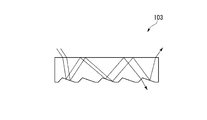
- FIG. 16A and FIG. 16B are schematic views showing a light guide body of a comparative example.
- FIG. 16A is a view showing the light guide body 103 of Comparative Example 1
- FIG. 16B is a view showing the light guide body 203 of Comparative Example 2.
- the shape which looked at the light guide body 103 of the comparative example 1 and the light guide body 203 of the comparative example 2 from the Z direction was set to the same dimensions as those of the first embodiment.
- the groove shapes (steeply inclined surface angle, gently inclined surface angle, groove width, flat portion width) of the light guide body 103 of the comparative example 1 and the light guide body 203 of the comparative example 2 are also described in the first embodiment. The dimensions were the same.
- the light guide body 103 of Comparative Example 1 has a configuration in which a plurality of grooves are formed on one surface of the flat plate (the surface opposite to the light incident surface).
- the end face arrival rate is 11% at a waveguide distance of 10 cm, and 5% at a waveguide distance of 30 cm. It was 0.1% at a distance of 100 cm (see Table 1).
- the light guide 203 of Comparative Example 2 has a configuration in which a plurality of grooves are formed on one surface (surface opposite to the light incident surface) of the trapezoidal member when viewed from the side.
- the end face arrival rate is 45% at a waveguide distance of 10 cm, and 40% at a waveguide distance of 30 cm. It was 36% at a distance of 100 cm (see Table 1).
- the light guide unit 2 in which the first light guide 3 and the second light guide 5 are stacked 65% light is incident on the solar cell element 7 regardless of the waveguide distance. be able to.
- the power generation amount per 100 cm square region is 260W.
- the power generation amount is 120 to 130 mW. Therefore, when power generation is performed with a compound solar cell using the light guide unit 2 in which the first light guide 3 and the second light guide 5 are stacked, it is twice as much as when crystalline silicon solar cells are spread. The above power generation amount can be obtained.
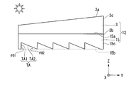
- FIG. 6 is a cross-sectional view showing the light guide unit 12 of this modification.
- the same components as those in FIG. 2 used in the above embodiment are denoted by the same reference numerals, and description thereof is omitted.
- the second light guide 15 is a plate-like member having a first main surface 15a and a second main surface 15b perpendicular to the Z axis (parallel to the XY plane).
- the first main surface 15 a of the second light guide 15 is a flat surface parallel to the second main surface 3 b of the first light guide 3.
- the light incident on the second main surface 15 b of the second light guide 15 from the first main surface 3 a of the first light guide 3, passes through the first light guide 3, and enters the second light guide 15.
- a reflection surface (slowly inclined surface TA2) that reflects light and changes the traveling direction of the light is formed.
- the second light guide 15 for example, a highly transparent organic material or inorganic material such as acrylic resin, polycarbonate resin, or glass is used.
- the second main surface 15b of the second light guide 15 is provided with a plurality of grooves TA extending in the X direction.
- the groove TA is a right triangle having a vertical surface TA1 formed at an angle perpendicular to a surface parallel to the XY plane and an inclined surface TA2 inclined at a predetermined angle with respect to a surface parallel to the XY plane. It is a groove.
- the groove TA is formed, for example, by injection molding a resin (for example, PMMA) using a mold.
- channel TA can also be formed by cutting the 2nd main surface 15b of the 2nd light guide 15 originally flat.
- the second main surface 15b of the second light guide 15 is provided with a plurality of such grooves TA in the Y direction so that the vertical surface TA1 and the inclined surface TA2 are in contact with each other.
- the shapes and sizes of the plurality of grooves TA provided in the second main surface 15b are all the same.
- the second light guide 15 has dimensions of 100 mm ⁇ 100 mm in the length and breadth (the x-axis direction and the y-axis direction in FIG. 6) of the rectangle that forms the first main surface 15a.
- the thickness (dimension in the z-axis direction in FIG. 2) is 1 mm
- the angle ⁇ B1 is 90 °
- the angle ⁇ B2 is 42 °
- the width of one groove TA in the Y direction is 100 ⁇ m.
- the vertical and horizontal dimensions, thickness, angle ⁇ B1, angle ⁇ B2, and width of the groove T in the Y direction are not limited to these.
- FIG. 7 is a cross-sectional view showing the light guide unit 22 of this modification.
- the same components as those in FIG. 2 used in the above embodiment are denoted by the same reference numerals, and the description thereof is omitted.
- the first light guide 23 is a trapezoidal member having a first main surface 23a and a second main surface 23b.
- the first main surface 23a of the first light guide 23 is viewed from the direction orthogonal to the second main surface 23b of the first light guide 23, and the first main surface 23a of the first light guide 23 and the first main surface 23a. Inclined so that the distance from the second main surface 23b of the light guide 23 gradually increases from the distance from the first end surface 23c of the first light guide 23 toward the first end surface 23c of the first light guide 23. is doing.
- the second light guide 25 is a trapezoidal member having a first main surface 25a and a second main surface 25b.
- the first main surface 25a of the second light guide 25 is viewed from the direction orthogonal to the second main surface 25b of the second light guide 25, and the first main surface 25a of the second light guide 25 and the first main surface 25a. Inclination so that the distance from the second main surface 25b of the light guide 25 gradually increases from the distance from the first end surface 25c of the second light guide 25 toward the first end surface 25c of the first light guide 25. is doing.
- the second main surface 25b of the second light guide 25 is provided with a plurality of grooves T extending in the X direction.
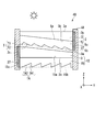
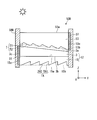
- FIG. 8 is a schematic diagram showing the solar cell module 30 of the present embodiment.
- the same components as those in FIGS. 1 and 2 used in the first embodiment are denoted by the same reference numerals, and the description thereof is omitted.
- the solar cell module 30 is emitted from the light guide unit 12, the light guide units 2 and 12 arranged to face each other, the solar cell element 37 that receives the light emitted from the light guide unit 2, and the light guide unit 12.
- maintains the light guide unit 2, the light guide unit 12, and the solar cell element 37 integrally are provided.
- a plurality of light guide units (here, one light guide unit 2 and one light guide unit 12 in total, two) are provided. ing. Thus, two light guide units may be provided, or three or more light guide units may be provided.
- Each light guide unit is laminated with the first main surface of the first light guide and the second main surface of the second light guide facing each other.
- the light guide unit 2 and the light guide unit 12 include the second main surface 5 b of the second light guide 5 of the light guide unit 2 and the first light guide 3 of the light guide unit 12.
- the first main surface 3a is stacked so as to face each other.
- the light guide units are arranged such that the first end faces of the first light guides face each other in the same direction.
- the light guide unit 2 and the light guide unit 12 include the first end surface 3 c of the first light guide 3 of the light guide unit 2 and the first light guide 3 of the light guide unit 12. It arrange
- part of the light incident on the light guide unit 2 propagates through the light guide unit 2 and is guided to the solar cell element 37 to contribute to power generation.
- the remaining part is emitted from the light guide unit 2 and then propagates through the light guide unit 12 and is guided to the solar cell element 37 to contribute to power generation.
- the solar cell module 30 of this embodiment light from the outside can be propagated inside the light guide unit 2 and guided to the solar cell element 37, and the light transmitted through the light guide unit 2 can be guided.
- the light can be propagated inside the light unit 12 and guided to the solar cell element 37. Therefore, it is possible to reliably suppress a decrease in power generation efficiency.
- the first end faces 3c of the first light guides 3 of the light guide units 2 and 12 are arranged so as to face in the same direction, wiring for using the electric power taken out by the solar cell element 37 And the arrangement of the apparatus becomes simple. For example, when the installation positions of the solar cell elements 37 of the light guide units 2 and 12 are close to each other, it becomes easy to route the wiring and connect the devices to use the electric power taken out by the solar cell elements 37, The apparatus configuration can be simplified.
- FIG. 9 is a schematic diagram showing a solar cell module 30A of the present modification.
- the same components as those in FIG. 8 used in the above embodiment are denoted by the same reference numerals, and the description thereof is omitted.
- the solar cell module 30A includes light guide units 2 and 12 arranged to face each other, a light collecting member 36 that collects light emitted from each light guide unit 2 and 12, and a light collecting member 36.
- a solar cell element 37 that receives the collected light, and a frame body 38A that integrally holds the light guide unit 2, the light guide unit 12, and the solar cell element 37 are provided.
- the condensing member 36 includes the first end surface 3 c of the first light guide 3 of the light guide unit 2, the first end surface 5 c of the second light guide 5, and the first end surface 5 c of the light guide unit 12.
- a light incident surface 36a facing each of the first end surface 3c and the first end surface 15c of the second light guide 15, a light emitting surface 36b for emitting light incident from the light incident surface 36a, and a light incident surface 36a.
- a reflecting surface 36c that reflects light and propagates it to the light exit surface 36b.
- the condensing member 36 has, for example, a quadrangular frustum shape having the light incident surface 36a as a bottom surface, the light emitting surface 36b as a top surface, and the reflecting surface 36c as a side surface.
- the solar cell element 37 is disposed with its light receiving surface facing the light exit surface 36 b of the light collecting member 36.
- the power generation efficiency in the solar cell element 37 is increased. That is, in the solar cell element 37, the power generation efficiency changes depending on the illuminance of incident light. If the illuminance is too small, the power generation efficiency is lowered. If the illuminance is too high, the power generation efficiency is saturated.
- the illuminance distribution is made uniform by the light collecting member 36, generally high power generation efficiency can be realized over the entire light receiving surface of the solar cell element 37. Therefore, compared with the case where the illuminance distribution is not made uniform by the light collecting member 36, the power generation efficiency is increased.
- since light can be condensed by the condensing member 36 it is sufficient to provide only one solar cell element 37, and the area of the solar cell element 37 can be kept small. Therefore, an increase in member cost can be suppressed.
- FIG. 10 is a schematic diagram showing the solar cell module 40 of the present embodiment.
- the same components as those in FIG. 8 used in the second embodiment are denoted by the same reference numerals, and the description thereof is omitted.
- the solar cell module 40 includes light guide units 2 and 12 arranged to face each other, a solar cell element 37 that receives light emitted from the light guide unit 2, and the light guide unit 12.
- the solar cell element 37 that receives light, and the frame body 48 that integrally holds the light guide unit 2, the light guide unit 12, and the solar cell element 37 are provided.
- Each light guide unit is arranged such that the first end faces of the first light guides face in opposite directions.
- the light guide unit 2 and the light guide unit 12 include the first end surface 3 c of the first light guide 3 of the light guide unit 2 and the first light guide 3 of the light guide unit 12. It arrange
- the light guide unit 2 and the light guide unit 2 are compared with the configuration in which the first end surfaces of the first light guides of the light guide units are oriented in the same direction.
- a gap between the light guide unit 12 can be reduced.
- the thickness of the solar cell module 40 (between the first main surface 3a of the first light guide 3 of the light guide unit 2 and the second main surface 15b of the second light guide 15 of the light guide unit 12). Can be reduced. Therefore, the transportation cost and installation cost of the solar cell module 40 can be reduced.
- FIG. 11 is a schematic diagram showing the solar cell module 50 of the present embodiment.
- the same components as those in FIG. 8 used in the second embodiment are denoted by the same reference numerals, and the description thereof is omitted.
- the solar cell module 50 includes a third light guide 53, a light guide unit 12, a solar cell element 37 that receives light emitted from the third light guide 53, and a light guide.
- the solar cell element 37 which receives the light inject
- the third light guide 53 is disposed on the light incident side of the light guide unit 12.
- the third light guide 53 includes a first main surface 53a that is a light incident surface, a second main surface 53b that faces the first main surface 53a, and a first end surface 53c that is a light emission surface.
- the third light guide 53 is a trapezoidal member having a first main surface 53a and a second main surface 53b.
- the first main surface 53a of the first light guide 33 is viewed from the direction orthogonal to the second main surface 33b of the first light guide 33, and the first main surface 33a of the first light guide 33 and the first main surface 33a.
- the angle ⁇ D of the first light guide 33 is larger than the angle ⁇ A of the first light guide rod of the light guide unit 12 ( ⁇ D> ⁇ A).
- a plurality of grooves T extending in the X direction are provided on the second main surface 53 b of the third light guide 53.
- FIG. 12 is a diagram for explaining the action of the reflection surface in the third light guide 53 and the light guide unit 12 of the solar cell module 50 of the present embodiment. In FIG. 12, only the third light guide 53 and the light guide unit 12 are shown for convenience.
- the third light guide 53 As shown in FIG. 12, most of the light incident on the first main surface 53 a of the third light guide 53 is transmitted through the third light guide 53.
- the light transmitted through the third light guide 53 propagates in the light guide unit 12 toward the first end face 3c and the first end face 15c.
- the first main surface 3a of the first light guide 3 of the light guide unit 12 does not satisfy the total reflection condition, and the third light guide 53 There is light incident on the two principal surfaces 53b.
- the light incident on the second main surface 53 b of the third light guide 53 without satisfying the total reflection condition on the first main surface 3 a of the first light guide 3 of the light guide unit 12 is the third light guide 53.
- the first main surface 53 a is totally reflected and propagates in the third light guide 53 toward the first end surface 53 c of the third light guide 53.
- the angle ⁇ D of the third light guide 53 is larger than the angle ⁇ A of the first light guide 3 of the light guide unit 12 ( ⁇ D> ⁇ A). Therefore, the incident angle ⁇ 3b when entering the first main surface 53a of the third light guide 53 is larger than the refraction angle ⁇ 3a when entering the second main surface 53b of the third light guide 53. Therefore, the light that has entered the third light guide 53 without satisfying the total reflection condition on the first main surface 3 a of the first light guide 3 of the light guide unit 12 is the first light of the third light guide 53.
- the main surface 53 a satisfies the total reflection condition, and is easily reflected toward the first end surface 53 c of the third light guide 53.
- the third light guide 53 having a uniform refractive index is installed instead of the light guide unit 2, the light guide having light guides having different refractive indexes.
- the cost can be reduced compared to a configuration in which a plurality of body units are provided (a configuration including the light guide unit 2 and the light guide unit 12).
- FIG. 13 is a schematic diagram showing a solar cell module 50A of this modification.
- the same components as those in FIG. 11 used in the above embodiment are denoted by the same reference numerals, and the description thereof is omitted.
- the solar cell module 50A has a third light guide 53, a light guide unit 12, and a light collecting unit configured to condense light emitted from the third light guide 53 and the light guide unit 12.
- the condensing member 56 includes the first end surface 53 c of the third light guide 53, the first end surface 3 c of the first light guide 3 of the light guide unit 12, and the first end surface 15 c of the second light guide 15.
- the condensing member 56 has, for example, a quadrangular frustum shape having the light incident surface 56a as a bottom surface, the light exit surface 56b as a top surface, and the reflecting surface 56c as a side surface.
- the solar cell element 37 is disposed with the light receiving surface facing the light emitting surface 56 b of the light collecting member 56.
- the power generation efficiency in the solar cell element 37 is increased. That is, in the solar cell element 37, the power generation efficiency changes depending on the illuminance of incident light. If the illuminance is too small, the power generation efficiency is lowered. If the illuminance is too high, the power generation efficiency is saturated.
- the illuminance distribution is made uniform by the condensing member 56, generally high power generation efficiency can be realized over the entire light receiving surface of the solar cell element 37. Therefore, compared with the case where the illuminance distribution is not made uniform by the light collecting member 56, the power generation efficiency is increased.
- since light can be condensed by the condensing member 56 it is sufficient to provide only one solar cell element 37, and the area of the solar cell element 37 can be kept small. Therefore, an increase in member cost can be suppressed.
- FIG. 14 is a schematic diagram showing a solar cell module 50B of the present modification.
- the same components as those in FIG. 11 used in the fourth embodiment are denoted by the same reference numerals, and the description thereof is omitted.
- the solar cell module 50B includes a third light guide 53, a light guide unit 12, a solar cell element 37 that receives light emitted from the third light guide 53, and a light guide.
- a solar cell element 37 that receives light emitted from the unit 12, and a frame body 58 ⁇ / b> B that integrally holds the third light guide 53, the light guide unit 12, and the solar cell element 37 are provided.
- the first end surface 53c of the third light guide 53 and the first end surface 3c of the first light guide 3 of the light guide unit 12 are opposite to each other. It is arranged in the state of facing.
- the first end surface 53c of the third light guide 53 and the first end surface 3c of the first light guide 3 of the light guide unit 12 are arranged to face the same direction.
- the gap between the third light guide 53 and the light guide unit 12 can be reduced.
- the thickness of the solar cell module 50B (the distance between the first main surface 53a of the third light guide 53 and the second main surface 15b of the second light guide 15 of the light guide unit 12) is reduced. be able to. Therefore, the transportation cost and installation cost of the solar cell module 50B can be reduced.
- FIG. 15 is a schematic configuration diagram of the solar power generation device 1000.
- the solar power generation apparatus 1000 includes a solar cell module 1001 that converts sunlight energy into electric power, an inverter (DC / AC converter) 1004 that converts DC power output from the solar cell module 1001 into AC power, A storage battery 1005 that stores DC power output from the battery module 1001.
- a solar cell module 1001 that converts sunlight energy into electric power
- an inverter (DC / AC converter) 1004 that converts DC power output from the solar cell module 1001 into AC power
- a storage battery 1005 that stores DC power output from the battery module 1001.
- the solar cell module 1001 includes a light guide body 1002 that collects sunlight, and a solar cell element 1003 that generates power using sunlight collected by the light guide body 1002.
- a solar cell module 1001 for example, the solar cell module described in the first to fourth embodiments is used.
- the solar power generation apparatus 1000 supplies power to the external electronic device 1006.
- the electronic device 1006 is supplied with power from the auxiliary power source 1007 as necessary.
- the photovoltaic power generation apparatus 1000 includes the above-described solar cell module according to the present invention, the photovoltaic power generation apparatus 1000 has a high power generation efficiency.
- the technical scope of the present invention is not limited to the above embodiment, and various modifications can be made without departing from the spirit of the present invention.
- the shape of a light guide is not limited to a plate-shaped body,
- a rod-shaped body may be sufficient and can be changed suitably.
- the shape, size, number, arrangement, constituent material, manufacturing method, and the like of various components in the above embodiment are not limited to those illustrated in the above embodiment, and can be changed as appropriate.
- the present invention can be used for a solar cell module or a solar power generation device.
Landscapes
- Photovoltaic Devices (AREA)
Abstract
太陽電池モジュールは、第1導光体と第2導光体とを有する導光体ユニットと、導光体ユニットから射出された光を受光する太陽電池素子とを備える。第1導光体は、第1主面と第2主面と第1主面および第2主面に接する第1端面とを有し、外部からの光を第1主面から入射させ内部を伝播させて第1端面から射出させる。第2導光体は、第1主面と第2主面とを有し、第1導光体の屈折率よりも低い屈折率を有する。第1導光体と第2導光体とは、第1導光体の第2主面と第2導光体の第1主面とが対向する。太陽電池素子は、第1導光体の第1端面から射出された光を受光する。第2導光体の第2主面に、第1導光体の第1主面から入射して第1導光体を透過し、第2導光体に入射した光を反射させてその光の進行方向を変更する反射面が形成される。第1導光体の厚みは、第1導光体の第1端面の遠くから第1導光体の第1端面に近づくにつれて徐々に厚くなっている。
Description
本発明は、太陽電池モジュールおよび太陽光発電装置に関するものである。
従来の太陽光発電装置は、複数の太陽電池パネルを太陽に向けて一面に敷き詰めた形態のものが一般的であった。一例として、建物の屋根に架台を設置し、架台上に複数の太陽電池パネルを敷き詰めた形態の太陽光発電装置が知られている。一般に、太陽電池パネルは不透明な半導体で構成されており、積層して配置することができない。そのため、太陽光発電装置において、電力量を確保するためには大面積の太陽電池パネルが必要となる。
ところが、屋根のような限られた場所に装置を設置しなければならないという制約があり、得られる電力量に限界があった。
ところが、屋根のような限られた場所に装置を設置しなければならないという制約があり、得られる電力量に限界があった。
そこで、入射した太陽光を太陽電池に導くための導光部材を備えた太陽電池が提案されている(下記の特許文献1参照)。特許文献1に記載の太陽電池は、複数のV字状溝が形成された、側面形状が略直角三角形の導光部材を備え、導光部材の端面に太陽電池が取り付けられている。
しかしながら、特許文献1の技術では、導光部材のサイズを大きくした場合、入射光を導光部材の内部で伝播させて端面に集光させる過程において、入射光が複数のV字状溝の反射面で複数回反射される。これにより、入射光の反射面における反射角度が変わり、入射光が反射面において全反射条件を満たさなくなり外部へ抜けてしまう。その結果、太陽電池への入光効率が低下し、発電効率が低下してしまう。
本発明は、上記の課題を解決するためになされたものであって、発電効率の低下を抑制することが可能な太陽電池モジュールおよび太陽光発電装置の提供を目的とする。
(1) 上記の目的を達成するために、本発明の第1の態様による太陽電池モジュールは、第1導光体と第2導光体とを有する導光体ユニットと、前記導光体ユニットから射出された光を受光する太陽電池素子と、を備え、前記第1導光体は、第1主面と第2主面と前記第1主面および前記第2主面に接する第1端面とを有し、外部からの光を前記第1主面から入射させ内部を伝播させて前記第1端面から射出させ、前記第2導光体は、第1主面と第2主面を有し、且つ、前記第1導光体の屈折率よりも低い屈折率を有し、前記第1導光体と前記第2導光体とは、前記第1導光体の第2主面と前記第2導光体の第1主面とが対向し、前記太陽電池素子は、前記第1導光体の第1端面から射出された光を受光し、前記第2導光体の第2主面に、前記第1導光体の第1主面から入射して前記第1導光体を透過し、前記第2導光体に入射した光を反射させて当該光の進行方向を変更する反射面が形成され、前記第1導光体の厚みは、当該第1導光体の第1端面の遠くから当該第1導光体の第1端面に近づくにつれて徐々に厚くなっている。
(2) 本発明の第1の態様による太陽電池モジュールにおいて、前記第1導光体と前記第2導光体とは、直接接触し、もしくは前記第1導光体の屈折率と前記第2導光体の屈折率との間の屈折率を有する接着部材を挟んで接着されていてもよい。
(3) 本発明の第1の態様による太陽電池モジュールにおいて、前記第1導光体の第1主面は、前記第2導光体の反射面で反射して前記第1導光体に入射した光を反射させて当該光の進行方向を変更する反射面として機能していてもよい。
(4) 本発明の第1の態様による太陽電池モジュールにおいて、前記第2導光体の第1主面と前記第2導光体の第2主面とは互いに平行であってもよい。
(5) 本発明の第1の態様による太陽電池モジュールにおいて、前記第2導光体の第2主面には複数の溝が形成されており、前記各溝は、前記第2導光体の第2主面に対して所定の傾斜角をなすように傾斜した傾斜面を有し、前記傾斜面が前記第2導光体の反射面として機能していてもよい。
(6) 本発明の第1の態様による太陽電池モジュールにおいて、前記第1導光体の第1主面は平坦面となっていてもよい。
(7) 本発明の第1の態様による太陽電池モジュールにおいて、前記第1導光体の第2主面は平坦面となっており、前記第2導光体の第1主面は、前記第1導光体の第2主面と平行な平坦面となっていてもよい。
(8) 本発明の第1の態様による太陽電池モジュールにおいて、前記導光体ユニットは、複数設けられており、前記各導光体ユニットは、互いの前記第1導光体の第1主面と前記第2導光体の第2主面とを対向させて積層されていてもよい。
(9) 本発明の第1の態様による太陽電池モジュールにおいて、前記各導光体ユニットは、互いの前記第1導光体の第1端面どうしが同じ方向を向くように配置されていてもよい。
(10) 本発明の第1の態様による太陽電池モジュールにおいて、前記各導光体ユニットは、互いの前記第1導光体の厚みが当該第1導光体の第1端面の遠くから当該第1導光体の第1端面に近づくにつれて徐々に厚くなっており、且つ、互いの前記第1導光体の第1端面どうしが反対の方向を向くように配置されていてもよい。
(11) 本発明の第1の態様による太陽電池モジュールにおいて、前記導光体ユニットの光が入射する側には第3導光体が設けられ、前記第3導光体は、第1主面と第2主面と前記第1主面および前記第2主面に接する第1端面とを有し、外部からの光を自身の第1主面から入射させ内部を伝播させて自身の第1端面から射出させ、前記導光体ユニットは、前記第3導光体を透過した光を前記第1導光体の第1主面から入射させ内部を伝播させて前記第1導光体の第1端面から射出させ、前記第3導光体の第1主面は、前記第2導光体の第2主面で反射して前記第1導光体を透過し、前記第3導光体に入射した光を反射させて当該光の進行方向を変更する反射面として機能し、前記第3導光体の厚みは、当該第3導光体の第1端面から当該第3導光体の第1端面に近づくにつれて徐々に厚くなっていてもよい。
(12) 本発明の第1の態様による太陽電池モジュールにおいて、前記第1導光体の第1端面から射出された光を集光し、前記太陽電池素子に入射させる集光部材を備えていてもよい。
(13) 本発明の第1の態様による太陽電池モジュールにおいて、前記導光体ユニットを構成する前記第1導光体および前記第2導光体の双方の材料は、400nm以下の波長に対して透過性を有していてもよい。
(14) 本発明の第2の態様による太陽光発電装置は、第1導光体と第2導光体とを有する導光体ユニットと、前記導光体ユニットから射出された光を受光する太陽電池素子と、を備え、前記第1導光体は、第1主面と第2主面と前記第1主面および前記第2主面に接する第1端面とを有し、外部からの光を前記第1主面から入射させ内部を伝播させて前記第1端面から射出させ、前記第2導光体は、第1主面と第2主面とを有し、且つ、前記第1導光体の屈折率よりも低い屈折率を有し、前記第1導光体と前記第2導光体とは、前記第1導光体の第2主面と前記第2導光体の第1主面とが対向し、前記太陽電池素子は、前記第1導光体の第1端面から射出された光を受光し、前記第2導光体の第2主面に、前記第1導光体の第1主面から入射して前記第1導光体を透過し、前記第2導光体に入射した光を反射させて当該光の進行方向を変更する反射面が形成され、前記第1導光体の厚みは、当該第1導光体の第1端面の遠くから当該第1導光体の第1端面に近づくにつれて徐々に厚くなっている太陽電池モジュールを備える。
本発明によれば、発電効率の低下を抑制することが可能な太陽電池モジュールおよび太陽光発電装置を提供することができる。
[第1の実施形態]
図1は、本発明の第1実施形態の太陽電池モジュール1を示す斜視図である。
太陽電池モジュール1は、互いに対向して配置された第1導光体3と第2導光体5とを有する導光体ユニット2と、導光体ユニット2から射出された光を集光する集光部材6と、集光部材6で集光された光を受光する太陽電池素子7と、導光体ユニット2と集光部材6と太陽電池素子7とを一体に保持する枠体8と、を備えている。
図1は、本発明の第1実施形態の太陽電池モジュール1を示す斜視図である。
太陽電池モジュール1は、互いに対向して配置された第1導光体3と第2導光体5とを有する導光体ユニット2と、導光体ユニット2から射出された光を集光する集光部材6と、集光部材6で集光された光を受光する太陽電池素子7と、導光体ユニット2と集光部材6と太陽電池素子7とを一体に保持する枠体8と、を備えている。
第1導光体3は、光入射面である第1主面3aと、第1主面3aと対向する第2主面3bと、光射出面である第1端面3cと、を備えている。第2導光体5は、光入射面である第1主面5aと、第1主面5aと対向する第2主面5bと、光射出面である第1端面5cと、を備えている。第1導光体3と第2導光体5とは、第1導光体3の第2主面3bと第2導光体5の第1主面5aとが対向した状態で、第1導光体3の屈折率と第2導光体5の屈折率との間の屈折率を有する接着部材4を挟んで接着されている。
なお、第1導光体3と第2導光体5とは、第1導光体3の第2主面3bと第2導光体5の第1主面5aとが対向した状態で、直接接触していてもよい。また、第1導光体3と第2導光体5とは、空気層を介して固定されていてもよいし、板状部材を介して間接的に固定されていてもよい。
第1導光体3の第1主面3aと第2導光体5の第1主面5aは、互いに同じ方向(光入射側:+Z方向)を向いている。第1導光体3と第2導光体5とを光Lの入射方向に沿って積層することで、前段側(光Lが入射する側に近い側)の第1導光体3で取り込めなかった光を後段側(光Lが入射する側から遠い側)の第2導光体5の第2主面5bに形成された反射面で反射させ、太陽電池素子7で取り込むことが可能となる。
第1導光体3の第1端面3cと第2導光体5の第1端面5cは、互いに同じ向きを向いている。第1導光体3の第1端面3cと第2導光体5の第1端面5cは、XZ平面と平行な同一平面上に配置されており、第1導光体3の第1端面3cから射出された光と第2導光体5の第1端面5cから射出された光とが共通の集光部材6で集光できるようになっている。
第1導光体3は、第1主面3a及び第2主面3bを有する側面視台形の部材である。第1導光体3の厚みは、当該第1導光体3の第1端面3cの遠くから当該第1導光体3の第1端面3cに近づくにつれて徐々に厚くなっている。ここで、第1導光体3の厚みとは、当該第1導光体3の第2主面3bと直交する方向から視たときの、第1導光体3の第1主面3aと第1導光体3の第2主面3bとの間の距離である。言い換えると、第1導光体3の第1主面3aは、当該第1導光体3の第2主面3bと直交する方向から視て、第1導光体3の第1主面3aと第1導光体3の第2主面3bとの間の距離が第1導光体3の第1端面3cの遠くから第1導光体3の第1端面3cに近づくにつれて徐々に大きくなるよう傾斜している。第1導光体3の第1主面3a、第2主面3bは平坦面となっている。第1導光体3としては、例えば、アクリル樹脂、ポリカーボネート樹脂、ガラスなどの透明性の高い有機材料もしくは無機材料が用いられる。
本実施形態において、第1導光体3は、一例としてポリメタクリル酸メチル樹脂(PMMA)にジルコニア粒子を分散させた材料で形成されているものとする。ジルコニア粒子の平均粒径は20nm程度であり、光の波長に比べて十分に小さい。
本実施形態において、第1導光体3の屈折率n1は1.8である。第1導光体3の屈折率(1.8)は、PMMA樹脂にジルコニア粒子を成分比1:1で分散することにより得ることができる。
接着部材4は、第1導光体3の第2主面3bと第2導光体5の第1主面5aとを接着する部材である。接着部材4としては、例えば、アクリル系UV硬化型樹脂が用いられる。
接着部材4の厚み(第1導光体3の第2主面3bと第2導光体5の第1主面5aとの間の距離)は2μm程度、接着部材4の屈折率は1.5である。
接着部材4の厚み(第1導光体3の第2主面3bと第2導光体5の第1主面5aとの間の距離)は2μm程度、接着部材4の屈折率は1.5である。
第2導光体5は、Z軸に垂直な(XY平面と平行な)第1主面5a及び第2主面5bを有する板状部材である。第2導光体5の第1主面5aは、第1導光体3の第2主面3bと平行な平坦面となっている。第2導光体5の第2主面5bには、第1導光体3の第1主面3aから入射して第1導光体3を透過し、第2導光体5に入射した光を反射させて当該光の進行方向を変更する反射面(緩傾斜面T2)が形成されている。第2導光体5としては、例えば、アクリル樹脂、ポリカーボネート樹脂、ガラスなどの透明性の高い有機材料もしくは無機材料が用いられる。
第2導光体5の第2主面5bには、X方向に延びる複数の溝Tが設けられている。溝Tは、XY平面と平行な面に対して大きな角度で傾斜した急傾斜面T1と、XY平面と平行な面に対して小さな角度で傾斜した緩傾斜面T2と、を有するV字状の溝である。図1では、図面を簡略化するために、溝Tを数本しか記載していないが、実際には、幅100μm程度の細かい溝Tが多数本形成されている。溝Tは、例えば、金型を用いて樹脂(例えばPMMA)を射出成形することにより形成されている。なお、溝Tは、元々平坦な第2導光体5の第2主面5bを切削加工することによって形成することもできる。
本実施形態において、第2導光体5の屈折率n2は1.3である。第2導光体5の屈折率(1.3)は、PMMA樹脂に中空PMMA粒子を所定の比率で分散させることにより得ることができる。
第2導光体5の第2主面5bには、このような溝Tが、急傾斜面T1と緩傾斜面T2とが互いに接するようにY方向に複数設けられている。第2主面5bに設けられた複数の溝Tの形状及び大きさは、全て同じである。
図4は、導光体ユニット2の透過率特性を示す図である。図4において、横軸は光の波長、縦軸は導光体ユニット2の透過率である。なお、図4では、導光体ユニット2を構成する第1導光体3および第2導光体5の双方の材料として三菱レイヨン社製の「XY-0159」を用いたときの導光体ユニット2の透過率特性を示している。
外光を有効に取り込めるように、導光体ユニット2を構成する第1導光体3および第2導光体5の双方の材料は、400nm以上の波長に対して透過性を有するとともに、下限は400nm以下の波長に対しても透過性を有することが望ましい。例えば、360nm以上800nm以下の波長領域の光に対して90%以上、より好ましくは93%以上の透過率を有するものが好適である。例えば、シリコン樹脂基板や石英基板、或いは、PMMA樹脂基板においては三菱レイヨン社製の「アクリライト」(登録商標)のなかでUV吸収材を含まないものは、広い波長領域に光に対して高い透明性を有することから、好適である。
図1に戻り、集光部材6は、例えば、第1導光体3の第1端面3c、第2導光体5の第1端面5cから射出された光の強度分布を均一化して太陽電池素子7に射出するインテグレータ光学素子(ホモジナイザー)である。
集光部材6は、第1導光体3の第1端面3cおよび第2導光体5の第1端面5cと対向する光入射面6aと、光入射面6aから入射した光を射出する光射出面6bと、光入射面6aから入射した光を反射させて光射出面6bに伝播させる反射面6cと、を備えている。集光部材6は、例えば、光入射面6aを底面、光射出面6bを上面、反射面6cを側面とする四角錐台の形状を有する。
集光部材6は、例えば、PMMAなどの樹脂を射出成形することにより形成されている。反射面6cは、全反射により光を反射するものとされるが、反射面6cに金属膜又は誘電体多層膜からなる反射層を形成し、該反射層によって光を反射するようにしてもよい。
太陽電池素子7は、受光面を集光部材6の光射出面6bと対向させて配置されている。
集光部材6の光入射面6aに入射した導光体ユニット2からの光は、集光部材6の反射面6cで反射を繰り返すうちに照度分布が均一化される。そして、照度分布が均一化された光が太陽電池素子7に入射される。太陽電池素子7に入射する光の照度分布が均一化されることにより、太陽電池素子7の発電効率を高めることができる。
集光部材6の光入射面6aに入射した導光体ユニット2からの光は、集光部材6の反射面6cで反射を繰り返すうちに照度分布が均一化される。そして、照度分布が均一化された光が太陽電池素子7に入射される。太陽電池素子7に入射する光の照度分布が均一化されることにより、太陽電池素子7の発電効率を高めることができる。
太陽電池素子7としては、シリコン系太陽電池、化合物系太陽電池、有機系太陽電池などの公知の太陽電池を使用することができる。中でも、GaAs化合物半導体を用いた化合物系太陽電池は、高効率な発電が可能であることから、太陽電池素子7として好適である。化合物系太陽電池は、一般に高価であるが、導光体ユニット2及び集光部材6によって光Lを集光することができることから、太陽電池素子7の面積は小さく抑えられる。よって、部材コストの上昇は抑えられる。
枠体8は、第1導光体3の第1主面3aと対向する面に光Lを透過する透過面8aを備えている。透過面8aは枠体8の開口部であってもよく、枠体8の開口部に嵌め込まれたガラス等の透明部材であってもよい。枠体8の透過面8aとZ方向から見て重なる部分の第1導光体3の第1主面3aが、導光体ユニット2の光入射面である。また、第1導光体3の第1端面3c、第2導光体5の第1端面5cが導光体ユニット2の第1光射出面である。
図2は、本実施形態の導光体ユニット2の断面図である。図3は、本実施形態の第2導光体5の部分断面図である。なお、図2においては、便宜上、接着部材4の図示を省略している。
第1導光体3は、Y軸に対して角度θAをなす第1主面3aを有する断面視台形の部材である。角度θAは、太陽の日週運動等を考慮して、例えばθA<45°なる関係を満たすように設定されている。第1導光体3の寸法は、一例として、第2主面3bとなる矩形の縦横(図2のx軸方向およびy軸方向)の寸法が100mm×100mmであり、厚みの小さい方の厚さdA1(図2のz軸方向の寸法)が1mmであり、厚みの大きい方の厚さdA2(図2のz軸方向の寸法)が8mmであり、角度θAが5°である。なお、縦横の寸法、厚みの小さい方の厚さdA1、厚みの大きい方の厚さdA2、角度θAはこれに限定されない。
第2導光体5は、互いに平行な第1主面5aおよび第2主面5bを有する板状部材である。第2導光体5の第2主面5bには、第1主面5aから入射した光を反射させて光の進行方向を第1端面5cに向かう方向に変更する複数の溝Tが設けられている。溝Tは、Y軸に対して角度θB1をなす急傾斜面T1と、Y軸に対して角度θB2をなす緩傾斜面T2と、が稜線T3において交差するV字状の溝である。角度θB1と角度θB2はθB1>θB2なる関係を満たす。稜線T3を挟んで第1端面5c側に緩傾斜面T2が配置され、第1端面5cとは反対側に急傾斜面T1が配置されている。
第2導光体5の第2主面5bにおいて、隣り合う2つの溝Tの間には、平坦部Sが設けられている。平坦部Sを設けることで、緩傾斜面T2で反射された光が隣の溝Tの急傾斜面T1に入射しにくくなる。つまり、第2導光体5の内部を伝播する光が急傾斜面T1の影響を受けて当該光の第1主面5aまたは第2主面5bに対する入射角が小さくなり、導波条件が崩れ、光が外部に漏れてしまうことが抑制される。
第2導光体5の寸法は、一例として、第1主面5aとなる矩形の縦横(図2のx軸方向およびy軸方向)の寸法が100mm×100mmであり、第2導光体5の厚さdB(図2のz軸方向の寸法)が1mmであり、角度θB1が45°であり、角度θB2が15°であり、1本の溝TのY方向の幅P1が100μmであり、2本の溝Tの間の平坦部SのY方向の幅P2が50μmである。なお、縦横の寸法、厚さdB、角度θB1、角度θB2、溝TのY方向の幅P1、及び平坦部SのY方向の幅P2はこれに限定されない。
図2に示すように、緩傾斜面T2は、第1主面5aから入射した光L(例えば太陽光)を全反射して光の進行方向を第1導光体3の第1端面3cに向かう方向に変更する反射面として機能する。第1主面5aに対して斜めに入射した光Lは、緩傾斜面T2で反射して第2導光体5の内部を概ねY方向に伝播する。一方、急傾斜面T1は、第1主面5aに対して斜めに入射した光Lを透過し、当該光Lは第2主面5bから射出される。
XY平面と平行な面に対して小さな角度で入射する光Lは、第2導光体5内に入射することなく、第1導光体3内のみを伝播して第1端面3cに向かう。
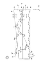
図5は、本実施形態の導光体ユニット2における反射面の作用を説明するための図である。図5において、符号L1は第1導光体3の第1主面3aに対して相対的に大きい入射角θ1aで入射する光、符号L2は第1導光体3の第1主面3aに対して相対的に小さい入射角θ2aで入射する光を示している。なお、図5においては、便宜上、接着部材4の図示を省略している。
図5に示すように、第1導光体3の第1主面3aに対して太陽光L1が入射角θ1aで入射したとすると、太陽光L1は第1主面3aにおいて屈折角θ1bで屈折して第1導光体3内に入射する。その後、第1導光体3の第2主面3b(第1導光体3と図示しない接着部材との間の界面)に入射角θ1cで入射した光は、当該界面において反射角θ1cで全反射し、第1導光体3内を第1端面3cに向けて伝播する。
一方、第1導光体3の第1主面3aに対して太陽光L2が入射角θ2aで入射したとすると、太陽光L2は第1主面3aにおいて屈折角θ2bで屈折して第1導光体3内に入射する。第1導光体3の第2主面3b(第1導光体3と図示しない接着部材との間の界面)に入射角θ2cで入射した光は、当該界面において屈折角θ2dで屈折して第2導光体5内に入射する。緩傾斜面T2に対して入射角θ2eで入射した光は、当該緩傾斜面T2に対して反射角θ2eで全反射し、第2導光体5内を第1端面3cに向けて伝播する。第2導光体5の第1主面5a(第2導光体5と図示しない接着部材との間の界面)に入射角θ2fで入射した光は、当該界面において屈折角θ2gで屈折して第1導光体3内に入射する。第1導光体3の第1主面3aに入射角θ2hで入射した光は、当該第1主面3aに対して反射角θ2hで全反射し、第1導光体3内を伝播する。第1導光体3の第1主面3aは、第2導光体5の反射面(緩傾斜面T2)で反射して第1導光体3に入射した光を反射させて当該光の進行方向を変更する反射面として機能する。第1導光体3の第2主面3b(第1導光体3と図示しない接着部材との間の界面)に入射角θ2iで入射した光は、当該第2主面3bに対して反射角θ2iで全反射し、第1導光体3内を第1端面3cに向けて伝播する。
具体的には、一例として、第1導光体3の角度θAを21度、第1導光体3の屈折率n1を1.8、第2導光体5の緩傾斜角度θB2を15度、第2導光体5の屈折率n2を1.3、外部の空気の屈折率n0を1.0とする。なお、説明の便宜上、図示しない接着部材の屈折率については考慮しないこととする。
この場合Snellの法則より、第1導光体3と第2導光体5との界面における臨界角は51度となる。ここで、第1導光体3の第1主面3aへの太陽光L1の入射角θ1aが70度以上であったとすると、太陽光L1が第1導光体3内に入射する際の屈折角θ1bは31度以上となる。すると、第1導光体3の第2主面3bへの光の入射角θ1cは52度以上となり(θ1c=θ1b+θA)、入射角θ1cが臨界角以上であるため(θ1c≧51度)、光L1は第1導光体3の第2主面3bで全反射する。当該第2主面3bで全反射した光は、第1導光体3内を第1端面3cに向けて伝播する。
一方、第2導光体5の緩傾斜面T2と外部の空気との界面における臨界角は56度となり、第1導光体3の第1主面3aと外部の空気との界面における臨界角は37度となる。
同様に、第1導光体3の第1主面3aへの太陽光L2の入射角θ2aが15度以上31度未満であったとすると、太陽光L2が第1導光体3内に入射する際の屈折角θ2bは8度以上17度未満となる。すると、第1導光体3の第2主面3bへの光の入射角θ2cは29度以上38度未満となり(θ2c=θ2b+θA)、入射角θ2cが臨界角未満であるため(θ2c<51度)、光L2は第1導光体3の第2主面3bを透過する。
同様に、第1導光体3の第1主面3aへの太陽光L2の入射角θ2aが15度以上31度未満であったとすると、太陽光L2が第1導光体3内に入射する際の屈折角θ2bは8度以上17度未満となる。すると、第1導光体3の第2主面3bへの光の入射角θ2cは29度以上38度未満となり(θ2c=θ2b+θA)、入射角θ2cが臨界角未満であるため(θ2c<51度)、光L2は第1導光体3の第2主面3bを透過する。
第1導光体3の第2主面3bへの光の入射角θ2cが29度以上38度未満であったとすると、光L2が第2導光体5内に入射する際の屈折角θ2dは45度以上57度未満となる。すると、第2導光体5の緩傾斜面T2への光の入射角θ2eは57度以上72度未満となり(θ2e=θ2d+θB2)、入射角θ2eが臨界角以上であるため(θ2e≧56度)、光L2は第2導光体5の緩傾斜面T2で全反射する。
第2導光体5の緩傾斜面T2での光の反射角θ2eが57度以上72度未満であったとすると、第2導光体5の第1主面5aへの光の入射角θ2fは72度以上87度未満となる(θ2d=θ2e+θB2)。すると、光が第1導光体3内に入射する際の屈折角θ2gは43度以上46度未満となる。すると、第1導光体3の第1主面3aへの光の入射角θ2hは64度以上67度未満となり(θ2f=θ2g+θA)、入射角θ2hが臨界角以上であるため(θ2f≧37度)、光L2は第1導光体3の第1主面3aで全反射する。
第1導光体3の第1主面3aでの反射角θ2hが64度以上67度未満であったとすると、第1導光体3の第2主面3bへの光の入射角θ2iは85度以上88度未満となる(θ2i=θ2h+θA)。すると、入射角θ2iが臨界角以上であるため(θ2i≧51度)、光L2は第1導光体3の第2主面3bで全反射する。第2主面3bで全反射した光は、第1導光体3内を第1端面3cに向けて伝播する。
本実施形態では、第1導光体3の反射面は、第1導光体3の第2主面3bと直交する方向から視たときの当該反射面と第1導光体3の第2主面3bとの間の距離が第1端面3cに近づくにつれて徐々に大きくなるよう傾斜している。そのため、第1導光体3内に入射する際の屈折角θ1bよりも第1導光体3の第2主面3bに入射する際の入射角θ1cのほうが大きくなる。したがって、第1導光体3内に入射した光は、第1導光体3の第2主面3bで全反射条件を満たし、第1導光体3の第1端面3cに向けて反射されやすくなる。
また、第1導光体3の屈折率n1よりも第2導光体5の屈折率n2のほうが小さい(n1>n2)。そのため、第1導光体3の第2主面3bに入射する際の入射角θ2cよりも第2導光体5に入射する際の屈折角θ2dのほうが大きくなる。したがって、第2導光体5内に入射した光は、第2導光体5の緩傾斜面T2で全反射条件を満たし、第1導光体3の第1端面3cに向けて反射されやすくなる。仮に、第2導光体5の屈折率n2が第1導光体3の屈折率n1よりも大きいとすると、第2導光体5内に入射した光は第2導光体5の緩傾斜面T2で全反射条件を満たさず、第2導光体5を透過して外部に漏れてしまいやすくなる。
第2導光体5内に入射した光は第2導光体5の緩傾斜面T2で全反射をすることにより第2導光体5内を伝播する角度(XY平面と平行な面と光の伝播方向とのなす角度)が浅くなる。そのため、第2導光体5の緩傾斜面T2で全反射した光が第1導光体3内に入射する際の屈折角θ2gは、光が最初に第1導光体3の第2主面3bに入射する際の入射角θ2cよりも大きくなる。したがって、第1導光体3内に入射した光は、第1導光体3の第1主面3aで全反射条件を満たし、第1導光体3の第1端面3cに向けて反射されやすくなる。
第1導光体3内に入射した光は第1導光体3の第1主面3aで全反射をすることにより第1導光体3内を伝播する角度(XY平面と平行な面と光の伝播方向とのなす角度)が浅くなる。そのため、第1導光体3の第1主面3aで全反射した光が第1導光体3の第2主面3bに入射する際の入射角θ2iは、最初に第1導光体3内に入射した光が第1導光体3の第2主面3bに入射する際の入射角θ2cよりも大きくなる。したがって、第1導光体3の第1主面3aで全反射した光は、第1導光体3の第2主面3bで全反射条件を満たし、第1導光体3の第1端面3cに向けて反射されやすくなる。第1導光体3の第2主面3bで全反射条件を満たした光は、もはや第2導光体5内に入射することなく、第1導光体3内のみを伝播して第1端面3cに向かうこととなる。
すなわち、本実施形態においては、第2導光体5の第2主面5bに形成された溝Tの緩傾斜面T2が第2導光体5内に入射した光を反射させて当該光の進行方向を変更する反射面となり、第1導光体3の第1主面3aが第2導光体5の反射面で反射して第1導光体3内に入射した光を反射させて当該光の進行方向を第1端面3cに向かう方向に変更する反射面となる。
本実施形態の太陽電池モジュール1においては、第1導光体3および第2導光体5を備えているので、外部からの光を第1導光体3の内部で伝播させて太陽電池素子7に導くことができ、さらに第1導光体3を透過した光を第2導光体5の内部で伝播させて太陽電池素子7に導くことができる。また、第1導光体3の反射面は、第1導光体3の第2主面3bと直交する方向から視たときの当該反射面と第1導光体3の第2主面3bとの間の距離が第1端面3cに近づくにつれて徐々に大きくなるよう傾斜しており、第1導光体3内に入射する際の屈折角θ2hよりも第1導光体3の第2主面3bに入射する際の入射角θ2iのほうが大きくなる。このため、第1導光体3内に入射した光は、第1導光体3の第2主面3bで全反射条件を満たし、太陽電池素子7に導かれやすくなる。また、第1導光体3の屈折率n1よりも第2導光体5の屈折率n2のほうが小さいので(n1>n2)、第1導光体3の第2主面3bに入射する際の入射角θ2cよりも第2導光体5に入射する際の屈折角θ2dのほうが大きくなる。このため、第2導光体5内に入射した光は、第2導光体5の緩傾斜面T2で全反射条件を満たし、太陽電池素子7に導かれやすくなる。また、第2導光体5の緩傾斜面T2で反射されて第1導光体3内に入射した光は、第1導光体3の第1主面3aで全反射をすることにより第1導光体3内を伝播する角度(XY平面と平行な面と光の伝播方向とのなす角度)が浅くなる。このため、第1導光体3の第1主面3aで全反射した光は、第1導光体3の第2主面3bで全反射条件を満たし、太陽電池素子7に導かれやすくなる。したがって、発電効率の低下を抑制することが可能な太陽電池モジュール1を提供することができる。
また、第2導光体5の第1主面5aと第2導光体5の第2主面5bとが互いに平行であるので、第2導光体5に反射面を形成することが容易となる。例えば、導光体本体として板状部材を用意し、当該板状部材の一方の面を切削加工等して反射面を形成することができる。これに対して、第2導光体5の第1主面5aと第2導光体5の第2主面5bとが互いに非平行であると、導光体本体を金型成形等により作製して新たに用意する必要があり手間がかかる。
また、第2導光体5の第2主面5bに複数の溝Tが形成され、溝Tの緩傾斜面T2が反射面として機能するので、光が当該反射面で反射して第1導光体3に入射する際の入射角θ2fを調整することが容易となる。例えば、緩傾斜面T2の傾斜角θB2を大きくすれば第1導光体3に入射する際の入射角θ2fは大きくなり、緩傾斜面T2の傾斜角θB2を小さくすれば第1導光体3に入射する際の入射角θ2fは小さくなる。
また、第1導光体3の第1主面3aは平坦面となっているので、光が第1導光体3内に入射して第2主面3bに入射する際の入射角θ1cを調整することが容易となる。例えば、第1主面3aの傾斜角度θAを大きくすれば第2主面3bに入射する際の入射角θ1cは大きくなり、傾斜角度θAを小さくすれば第2主面3bに入射する際の入射角θ1cは小さくなる。
また、第1導光体3の第2主面3bは平坦面となっており、第2導光体5の第1主面5aは第1導光体3の第2主面3bと平行な平坦面となっているので、第1導光体3と第2導光体5とを、直接接触させ、もしくは接着部材4を挟んで接着させやすくなる。
また、集光部材6によって太陽電池素子7には照度分布が均一化した光が入射する。そのため、太陽電池素子7における発電効率が高まる。すなわち、太陽電池素子7では、入射する光の照度によって発電効率が変化する。照度が小さすぎると発電効率が低下し、照度が高すぎると発電効率が飽和する。集光部材6によって照度分布を均一化すると、太陽電池素子7の受光面全体で概ね高い発電効率が実現することができる。よって、集光部材6で照度分布を均一化しない場合に比べて、発電効率が高まる。
また、導光体ユニット2を構成する第1導光体3および第2導光体5の双方の材料は400nm以下の波長に対して透過性を有するので、広い波長領域の光を透過することとなる。よって、外光を有効に取り込むことができる。
ここで、本発明者は、本実施形態の太陽電池モジュール1の効果を実証するために、光の端面到達率のシミュレーションを行った。ここで、光の端面到達率とは、導光体ユニット2の第1主面3aに入射する太陽光の照射量の割合を100%としたときに導光体ユニット2の射出端面(第1導光体3の第1端面3cおよび第2導光体5の第1端面5c)に到達する光量の割合(%)である。シミュレーションの条件として、光Lは導光体ユニット2の第1主面3aに対して斜めに入射するものとする(XY平面に対する入射角35度)。また、導光体ユニット2の第1主面3aに入射する光Lの光量は1Sun(1kW/cm2)とする。
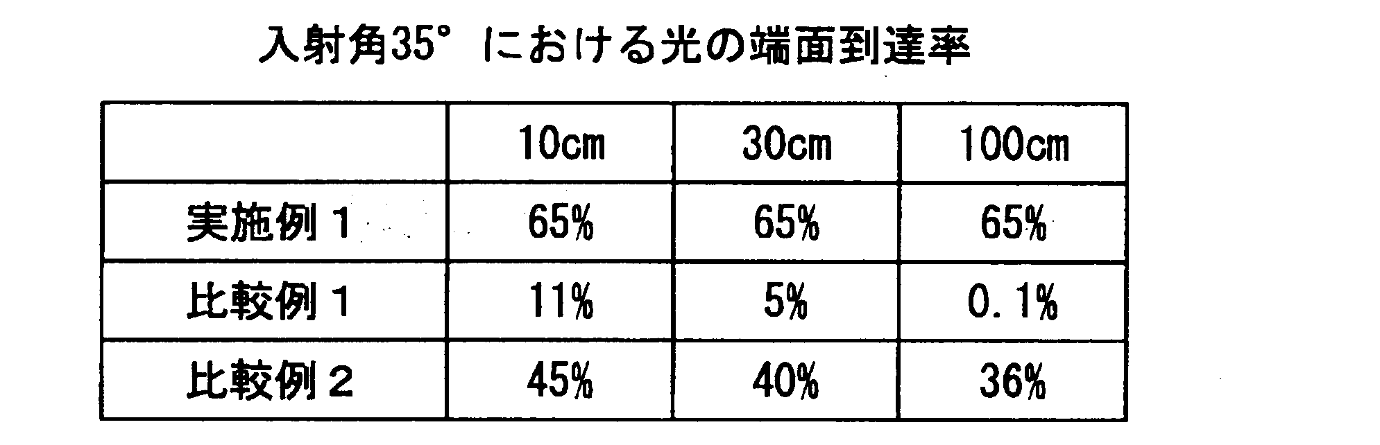
実施例1の導光体ユニット2は、Z方向から視た形状を10cm×10cmの四角形(10cm角)、30cm×30cmの四角形(30cm角)、100cm×100cmの四角形(100cm角)、とした3種類の形状を用いた。
第1導光体3は、PMMA樹脂にジルコニア粒子を分散させた材料を用いて形成し、屈折率(n1)を1.8とした。第1導光体3の厚みの小さい方の厚さ(dA1)を1mmとし、第1主面3aの傾斜角θAを5度とした。厚みの大きい方の厚さ(dA2)はdA1とθAとの関係で決まり、10cm角(導波距離10cm)で8mm、30cm角(導波距離30cm)で30mm、100cm角(導波距離100cm)で87mmとした。
接着部材4は、アクリル系UV硬化型樹脂を用い、屈折率を1.5とした。接着部材4の厚み(第1導光体3の第2主面3bと第2導光体5の第1主面5aとの間の距離)は2μm程度、接着部材4の屈折率は1.5である。
第2導光体5は、PMMA樹脂に中空PMMA粒子を分散させた材料を用いて形成、屈折率(n2)を1.3とした。第2導光体5の厚さ(dB)を1mmとし、急傾斜面T2の角度θB1を45度とし、緩傾斜面の角度θB2を15度とし、1本の溝TのY方向の幅P1を100μmとし、2本の溝Tの間の平坦部SのY方向の幅P2を50μmとした。
実施例1の導光体ユニット2に対して第1導光体3の第1主面3a側から太陽光を照射したときの端面到達率は、導波距離10cm、導波距離30cm、導波距離100cmにおいてそれぞれ65%であった(表1参照)。
第1導光体3は、PMMA樹脂にジルコニア粒子を分散させた材料を用いて形成し、屈折率(n1)を1.8とした。第1導光体3の厚みの小さい方の厚さ(dA1)を1mmとし、第1主面3aの傾斜角θAを5度とした。厚みの大きい方の厚さ(dA2)はdA1とθAとの関係で決まり、10cm角(導波距離10cm)で8mm、30cm角(導波距離30cm)で30mm、100cm角(導波距離100cm)で87mmとした。
接着部材4は、アクリル系UV硬化型樹脂を用い、屈折率を1.5とした。接着部材4の厚み(第1導光体3の第2主面3bと第2導光体5の第1主面5aとの間の距離)は2μm程度、接着部材4の屈折率は1.5である。
第2導光体5は、PMMA樹脂に中空PMMA粒子を分散させた材料を用いて形成、屈折率(n2)を1.3とした。第2導光体5の厚さ(dB)を1mmとし、急傾斜面T2の角度θB1を45度とし、緩傾斜面の角度θB2を15度とし、1本の溝TのY方向の幅P1を100μmとし、2本の溝Tの間の平坦部SのY方向の幅P2を50μmとした。
実施例1の導光体ユニット2に対して第1導光体3の第1主面3a側から太陽光を照射したときの端面到達率は、導波距離10cm、導波距離30cm、導波距離100cmにおいてそれぞれ65%であった(表1参照)。
図16A及び図16Bは、比較例の導光体を示す模式図である。図16Aは比較例1の導光体103を示す図であり、図16Bは比較例2の導光体203を示す図である。なお、比較例1の導光体103および比較例2の導光体203をZ方向から視た形状は、それぞれ実施例1と同様の寸法とした。また、比較例1の導光体103および比較例2の導光体203の溝の形状(急傾斜面の角度、緩傾斜面の角度、溝幅、平坦部幅)についても、それぞれ実施例1と同様の寸法とした。
図16Aに示すように、比較例1の導光体103は、平板の一方面(光入射面と反対側の面)に複数の溝が形成された構成となっている。比較例1の導光体103に対して光入射面側から太陽光を照射したときの端面到達率は、導波距離10cmにおいて11%であり、導波距離30cmにおいて5%であり、導波距離100cmにおいて0.1%であった(表1参照)。
図16Bに示すように、比較例2の導光体203は、側面視台形の部材の一方面(光入射面と反対側の面)に複数の溝が形成された構成となっている。比較例2の導光体203に対して光入射面側から太陽光を照射したときの端面到達率は、導波距離10cmにおいて45%であり、導波距離30cmにおいて40%であり、導波距離100cmにおいて36%であった(表1参照)。
このように、本実施形態の導光体ユニット2によれば、導波距離によらず、比較例1の導光体103および比較例2の導光体203よりも高い端面到達率を得ることができることが判った。
以上のように、第1導光体3と第2導光体5とを積層した導光体ユニット2を用いることで、導波距離によらず65%の光を太陽電池素子7に入射させることができる。太陽電池素子7として発電効率が40%の化合物系太陽電池を用いると、100cm角の領域当たり発電量は260Wである。100cm角の領域に、一般に用いられている結晶シリコン太陽電池を敷き詰めた場合、その発電量は120~130mWである。よって、第1導光体3と第2導光体5とを積層した導光体ユニット2を用いて化合物系太陽電池で発電を行うと、結晶シリコン太陽電池を敷き詰めた場合に比べて2倍以上の発電量を得ることができる。
[第1の実施形態の第1の変形例]
以下、本実施形態の第1の変形例について、図6を用いて説明する。
本変形例の導光体ユニット12の基本構成は上記実施形態と同様であり、溝TAの形状が上記実施形態と異なるのみである。
図6は、本変形例の導光体ユニット12を示す断面図である。
なお、図6において、上記実施形態で用いた図2と共通の構成要素には同一の符号を付し、その説明は省略する。
以下、本実施形態の第1の変形例について、図6を用いて説明する。
本変形例の導光体ユニット12の基本構成は上記実施形態と同様であり、溝TAの形状が上記実施形態と異なるのみである。
図6は、本変形例の導光体ユニット12を示す断面図である。
なお、図6において、上記実施形態で用いた図2と共通の構成要素には同一の符号を付し、その説明は省略する。
第2導光体15は、Z軸に垂直な(XY平面と平行な)第1主面15a及び第2主面15bを有する板状部材である。第2導光体15の第1主面15aは、第1導光体3の第2主面3bと平行な平坦面となっている。第2導光体15の第2主面15bには、第1導光体3の第1主面3aから入射して第1導光体3を透過し、第2導光体15に入射した光を反射させて当該光の進行方向を変更する反射面(緩傾斜面TA2)が形成されている。第2導光体15としては、例えば、アクリル樹脂、ポリカーボネート樹脂、ガラスなどの透明性の高い有機材料もしくは無機材料が用いられる。
第2導光体15の第2主面15bには、X方向に延びる複数の溝TAが設けられている。溝TAは、XY平面と平行な面に対して垂直な角度で形成された垂直面TA1と、XY平面と平行な面に対して所定の角度で傾斜した傾斜面TA2と、を有する直角三角形状の溝である。溝TAは、例えば、金型を用いて樹脂(例えばPMMA)を射出成形することにより形成されている。なお、溝TAは、元々平坦な第2導光体15の第2主面15bを切削加工することによって形成することもできる。
第2導光体15の第2主面15bには、このような溝TAが、垂直面TA1と傾斜面TA2とが互いに接するようにY方向に複数設けられている。第2主面15bに設けられた複数の溝TAの形状及び大きさは、全て同じである。
第2導光体15の寸法は、一例として、第1主面15aとなる矩形の縦横(図6のx軸方向およびy軸方向)の寸法が100mm×100mmであり、第2導光体15の厚さ(図2のz軸方向の寸法)が1mmであり、角度θB1が90°であり、角度θB2が42°であり、1本の溝TAのY方向の幅が100μmである。なお、縦横の寸法、厚さ、角度θB1、角度θB2、及び溝TのY方向の幅はこれに限定されない。
本変形例の導光体ユニット12においても、発電効率の低下を抑制することができる。
[第1の実施形態の第2の変形例]
以下、本実施形態の第2の変形例について、図7を用いて説明する。
本変形例の導光体ユニット22の基本構成は上記実施形態と同様であり、第1導光体23の第1主面23aが第2主面23bに対して所定の角度θC1だけ傾斜していることに加えて第2導光体25の第1主面25aも第2主面25bに対して所定の角度θC2だけ傾斜している点が上記実施形態と異なるのみである。
図7は、本変形例の導光体ユニット22を示す断面図である。
なお、図7において、上記実施形態で用いた図2と共通の構成要素には同一の符号を付し、その説明は省略する。
以下、本実施形態の第2の変形例について、図7を用いて説明する。
本変形例の導光体ユニット22の基本構成は上記実施形態と同様であり、第1導光体23の第1主面23aが第2主面23bに対して所定の角度θC1だけ傾斜していることに加えて第2導光体25の第1主面25aも第2主面25bに対して所定の角度θC2だけ傾斜している点が上記実施形態と異なるのみである。
図7は、本変形例の導光体ユニット22を示す断面図である。
なお、図7において、上記実施形態で用いた図2と共通の構成要素には同一の符号を付し、その説明は省略する。
第1導光体23は、第1主面23a及び第2主面23bを有する側面視台形の部材である。第1導光体23の第1主面23aは、当該第1導光体23の第2主面23bと直交する方向から視て、第1導光体23の第1主面23aと第1導光体23の第2主面23bとの間の距離が第1導光体23の第1端面23cの遠くから第1導光体23の第1端面23cに近づくにつれて徐々に大きくなるよう傾斜している。
第2導光体25は、第1主面25a及び第2主面25bを有する側面視台形の部材である。第2導光体25の第1主面25aは、当該第2導光体25の第2主面25bと直交する方向から視て、第2導光体25の第1主面25aと第1導光体25の第2主面25bとの間の距離が第2導光体25の第1端面25cの遠くから第1導光体25の第1端面25cに近づくにつれて徐々に大きくなるよう傾斜している。第2導光体25の第2主面25bには、X方向に延びる複数の溝Tが設けられている。
本変形例の導光体ユニット22においても、発電効率の低下を抑制することができる。
[第2の実施形態]
以下、本発明の第2の実施形態について、図8を用いて説明する。
本実施形態の太陽電池モジュール30の基本構成は第1の実施形態と同様であり、導光体ユニットの設置数が第1の実施形態と異なるのみである。
図8は、本実施形態の太陽電池モジュール30を示す模式図である。
なお、図8において、第1の実施形態で用いた図1および図2と共通の構成要素には同一の符号を付し、その説明は省略する。
以下、本発明の第2の実施形態について、図8を用いて説明する。
本実施形態の太陽電池モジュール30の基本構成は第1の実施形態と同様であり、導光体ユニットの設置数が第1の実施形態と異なるのみである。
図8は、本実施形態の太陽電池モジュール30を示す模式図である。
なお、図8において、第1の実施形態で用いた図1および図2と共通の構成要素には同一の符号を付し、その説明は省略する。
太陽電池モジュール30は、互いに対向して配置された導光体ユニット2,12と、導光体ユニット2から射出された光を受光する太陽電池素子37と、導光体ユニット12から射出された光を受光する太陽電池素子37と、導光体ユニット2と導光体ユニット12と太陽電池素子37とを一体に保持する枠体38と、を備えている。
本実施形態の太陽電池モジュール30においては、図8に示すように、導光体ユニットが複数(ここでは導光体ユニット2を1つ、導光体ユニット12を1つの計2つ)設けられている。このように、導光体ユニットは2つ設けられていてもよいし、3つ以上設けられていてもよい。
各導光体ユニットは、互いの第1導光体の第1主面と第2導光体の第2主面とを対向させて積層されている。具体的には、導光体ユニット2と導光体ユニット12とは、導光体ユニット2の第2導光体5の第2主面5bと導光体ユニット12の第1導光体3の第1主面3aとが対向した状態で、積層されている。
各導光体ユニットは、互いの第1導光体の第1端面どうしが同じ方向を向くように配置されている。具体的には、導光体ユニット2と導光体ユニット12とは、導光体ユニット2の第1導光体3の第1端面3cと導光体ユニット12の第1導光体3の第1端面3cとが同じ方向を向いた状態で、配置されている。
図8に示すように、導光体ユニット2に入射した光の一部は、導光体ユニット2内部を伝播して太陽電池素子37に導かれて発電に寄与する。一方、残りの一部は、導光体ユニット2から射出された後、導光体ユニット12内部を伝播して太陽電池素子37に導かれて発電に寄与する。
本実施形態の太陽電池モジュール30においては、外部からの光を導光体ユニット2の内部で伝播させて太陽電池素子37に導くことができ、さらに、導光体ユニット2を透過した光を導光体ユニット12の内部で伝播させて太陽電池素子37に導くことができる。
したがって、発電効率の低下を確実に抑制することが可能となる。
したがって、発電効率の低下を確実に抑制することが可能となる。
また、各導光体ユニット2,12の第1導光体3の第1端面3cどうしが同じ方向を向くように配置されているので、太陽電池素子37で取り出した電力を利用するための配線や装置の配置が簡素なものとなる。例えば、各導光体ユニット2,12の太陽電池素子37の設置位置が近くにあると、各太陽電池素子37で取り出した電力を利用するための配線の引き回しや装置の接続が容易になり、装置構成を簡素化することができる。
[第2の実施形態の第1の変形例]
以下、本実施形態の第1の変形例について、図9を用いて説明する。
本変形例の太陽電池モジュール30Aの基本構成は上記実施形態と同様であり、集光部材36を備え、太陽電池素子37を1つのみ備えている点が上記実施形態と異なるのみである。
図9は、本変形例の太陽電池モジュール30Aを示す模式図である。
なお、図9において、上記実施形態で用いた図8と共通の構成要素には同一の符号を付し、その説明は省略する。
以下、本実施形態の第1の変形例について、図9を用いて説明する。
本変形例の太陽電池モジュール30Aの基本構成は上記実施形態と同様であり、集光部材36を備え、太陽電池素子37を1つのみ備えている点が上記実施形態と異なるのみである。
図9は、本変形例の太陽電池モジュール30Aを示す模式図である。
なお、図9において、上記実施形態で用いた図8と共通の構成要素には同一の符号を付し、その説明は省略する。
太陽電池モジュール30Aは、互いに対向して配置された導光体ユニット2,12と、各導光体ユニット2,12から射出された光を集光する集光部材36と、集光部材36で集光された光を受光する太陽電池素子37と、導光体ユニット2と導光体ユニット12と太陽電池素子37とを一体に保持する枠体38Aと、を備えている。
集光部材36は、導光体ユニット2の第1導光体3の第1端面3cおよび第2導光体5の第1端面5c、導光体ユニット12の第1導光体3の第1端面3cおよび第2導光体15の第1端面15cのそれぞれと対向する光入射面36aと、光入射面36aから入射した光を射出する光射出面36bと、光入射面36aから入射した光を反射させて光射出面36bに伝播させる反射面36cと、を備えている。集光部材36は、例えば、光入射面36aを底面、光射出面36bを上面、反射面36cを側面とする四角錐台の形状を有する。
太陽電池素子37は、受光面を集光部材36の光射出面36bと対向させて配置されている。
本変形例の太陽電池モジュール30Aにおいては、集光部材36によって太陽電池素子37には照度分布が均一化した光が入射する。そのため、太陽電池素子37における発電効率が高まる。すなわち、太陽電池素子37では、入射する光の照度によって発電効率が変化する。照度が小さすぎると発電効率が低下し、照度が高すぎると発電効率が飽和する。集光部材36によって照度分布を均一化すると、太陽電池素子37の受光面全体で概ね高い発電効率が実現することができる。よって、集光部材36で照度分布を均一化しない場合に比べて、発電効率が高まる。また、集光部材36によって光を集光することができることから、太陽電池素子37を1つだけ設ければよく、太陽電池素子37の面積は小さく抑えられる。よって、部材コストの上昇は抑えられる。
[第3の実施形態]
以下、本発明の第3の実施形態について、図10を用いて説明する。
本実施形態の太陽電池モジュール40の基本構成は第2の実施形態と同様であり、導光体ユニットの配置向きが第2の実施形態と異なるのみである。
図10は、本実施形態の太陽電池モジュール40を示す模式図である。
なお、図10において、第2の実施形態で用いた図8と共通の構成要素には同一の符号を付し、その説明は省略する。
以下、本発明の第3の実施形態について、図10を用いて説明する。
本実施形態の太陽電池モジュール40の基本構成は第2の実施形態と同様であり、導光体ユニットの配置向きが第2の実施形態と異なるのみである。
図10は、本実施形態の太陽電池モジュール40を示す模式図である。
なお、図10において、第2の実施形態で用いた図8と共通の構成要素には同一の符号を付し、その説明は省略する。
太陽電池モジュール40は、互いに対向して配置された導光体ユニット2,12と、導光体ユニット2から射出された光を受光する太陽電池素子37と、導光体ユニット12から射出された光を受光する太陽電池素子37と、導光体ユニット2と導光体ユニット12と太陽電池素子37とを一体に保持する枠体48と、を備えている。
各導光体ユニットは、互いの第1導光体の第1端面どうしが反対の方向を向くように配置されている。具体的には、導光体ユニット2と導光体ユニット12とは、導光体ユニット2の第1導光体3の第1端面3cと導光体ユニット12の第1導光体3の第1端面3cとが反対の方向を向いた状態で、配置されている。
本実施形態の太陽電池モジュール40においては、各導光体ユニットの互いの第1導光体の第1端面どうしが同じ方向を向くように配置された構成に比べて、導光体ユニット2と導光体ユニット12との間の隙間を小さくすることができる。このため、太陽電池モジュール40の厚み(導光体ユニット2の第1導光体3の第1主面3aと導光体ユニット12の第2導光体15の第2主面15bとの間の距離)を小さくすることができる。よって、太陽電池モジュール40の輸送コスト、設置コストを低くすることができる。
[第4の実施形態]
以下、本発明の第4の実施形態について、図11を用いて説明する。
本実施形態の太陽電池モジュール50の基本構成は第2の実施形態と同様であり、導光体ユニット2に替えて屈折率が均一な第3導光体53が設置されている点が第2の実施形態と異なるのみである。
図11は、本実施形態の太陽電池モジュール50を示す模式図である。
なお、図11において、第2の実施形態で用いた図8と共通の構成要素には同一の符号を付し、その説明は省略する。
以下、本発明の第4の実施形態について、図11を用いて説明する。
本実施形態の太陽電池モジュール50の基本構成は第2の実施形態と同様であり、導光体ユニット2に替えて屈折率が均一な第3導光体53が設置されている点が第2の実施形態と異なるのみである。
図11は、本実施形態の太陽電池モジュール50を示す模式図である。
なお、図11において、第2の実施形態で用いた図8と共通の構成要素には同一の符号を付し、その説明は省略する。
太陽電池モジュール50は、互いに対向して配置された第3導光体53、導光体ユニット12と、第3導光体53から射出された光を受光する太陽電池素子37と、導光体ユニット12から射出された光を受光する太陽電池素子37と、第3導光体53と導光体ユニット12と太陽電池素子37とを一体に保持する枠体58と、を備えている。
第3導光体53は、導光体ユニット12の光が入射する側に配置されている。第3導光体53は、光入射面である第1主面53aと、第1主面53aと対向する第2主面53bと、光射出面である第1端面53cと、を備えている。第3導光体53は、第1主面53a及び第2主面53bを有する側面視台形の部材である。第1導光体33の第1主面53aは、当該第1導光体33の第2主面33bと直交する方向から視て、第1導光体33の第1主面33aと第1導光体33の第2主面33bとの間の距離が第1導光体33の第1端面33cの遠くから第1導光体33の第1端面33cに近づくにつれて徐々に大きくなるよう傾斜している。第1導光体33の角度θDは、導光体ユニット12の第1導光鯛の角度θAよりも大きい(θD>θA)。第3導光体53の第2主面53bには、X方向に延びる複数の溝Tが設けられている。
図12は、本実施形態の太陽電池モジュール50の第3導光体53および導光体ユニット12における反射面の作用を説明するための図である。なお、図12においては、便宜上、第3導光体53および導光体ユニット12のみを図示している。
図12に示すように、第3導光体53の第1主面53aに入射した光の大部分は第3導光体53を透過する。第3導光体53を透過した光は、導光体ユニット12内を第1端面3c、第1端面15cに向けて伝播する。
一方、導光体ユニット12内を伝播する光のうち、導光体ユニット12の第1導光体3の第1主面3aで全反射条件を満たさずに、第3導光体53の第2主面53bに入射する光がある。導光体ユニット12の第1導光体3の第1主面3aで全反射条件を満たさずに第3導光体53の第2主面53bに入射した光は、第3導光体53の第1主面53aで全反射して第3導光体53内を第3導光体53の第1端面53cに向けて伝播する。
本実施形態では、第3導光体53の角度θDは、導光体ユニット12の第1導光体3の角度θAよりも大きくなっている(θD>θA)。そのため、第3導光体53の第2主面53bに入射する際の屈折角θ3aよりも第3導光体53の第1主面53aに入射する際の入射角θ3bのほうが大きくなる。したがって、導光体ユニット12の第1導光体3の第1主面3aで全反射条件を満たさずに第3導光体53内に入射した光は、第3導光体53の第1主面53aで全反射条件を満たし、第3導光体53の第1端面53cに向けて反射されやすくなる。
本実施形態の太陽電池モジュール50においては、導光体ユニット2に替えて屈折率が均一な第3導光体53が設置されているので、互いに異なる屈折率を有する導光体を有する導光体ユニットを複数設けた構成(導光体ユニット2と導光体ユニット12とを備えた構成)に比べて、低コスト化を図ることができる。
[第4の実施形態の第1の変形例]
以下、本実施形態の第1の変形例について、図13を用いて説明する。
本変形例の太陽電池モジュール50Aの基本構成は上記実施形態と同様であり、集光部材36を備え、太陽電池素子37を1つのみ備えている点が上記実施形態と異なるのみである。
図13は、本変形例の太陽電池モジュール50Aを示す模式図である。
なお、図13において、上記実施形態で用いた図11と共通の構成要素には同一の符号を付し、その説明は省略する。
以下、本実施形態の第1の変形例について、図13を用いて説明する。
本変形例の太陽電池モジュール50Aの基本構成は上記実施形態と同様であり、集光部材36を備え、太陽電池素子37を1つのみ備えている点が上記実施形態と異なるのみである。
図13は、本変形例の太陽電池モジュール50Aを示す模式図である。
なお、図13において、上記実施形態で用いた図11と共通の構成要素には同一の符号を付し、その説明は省略する。
太陽電池モジュール50Aは、互いに対向して配置された第3導光体53、導光体ユニット12と、第3導光体53と導光体ユニット12とから射出された光を集光する集光部材56と、集光部材56で集光された光を受光する太陽電池素子37と、第3導光体53と導光体ユニット12と太陽電池素子37とを一体に保持する枠体58Aと、を備えている。
集光部材56は、第3導光体53の第1端面53c、導光体ユニット12の第1導光体3の第1端面3cおよび第2導光体15の第1端面15cのそれぞれと対向する光入射面56aと、光入射面56aから入射した光を射出する光射出面56bと、光入射面56aから入射した光を反射させて光射出面56bに伝播させる反射面56cと、を備えている。集光部材56は、例えば、光入射面56aを底面、光射出面56bを上面、反射面56cを側面とする四角錐台の形状を有する。
太陽電池素子37は、受光面を集光部材56の光射出面56bと対向させて配置されている。
本変形例の太陽電池モジュール50Aにおいては、集光部材56によって太陽電池素子37には照度分布が均一化した光が入射する。そのため、太陽電池素子37における発電効率が高まる。すなわち、太陽電池素子37では、入射する光の照度によって発電効率が変化する。照度が小さすぎると発電効率が低下し、照度が高すぎると発電効率が飽和する。集光部材56によって照度分布を均一化すると、太陽電池素子37の受光面全体で概ね高い発電効率が実現することができる。よって、集光部材56で照度分布を均一化しない場合に比べて、発電効率が高まる。また、集光部材56によって光を集光することができることから、太陽電池素子37を1つだけ設ければよく、太陽電池素子37の面積は小さく抑えられる。よって、部材コストの上昇は抑えられる。
[第4の実施形態の第2の変形例]
以下、本実施形態の第2の変形例について、図14を用いて説明する。
本変形例の太陽電池モジュール50Bの基本構成は第4の実施形態と同様であり、第3導光体53と導光体ユニット12との配置向きが第4の実施形態と異なるのみである。
図14は、本変形例の太陽電池モジュール50Bを示す模式図である。
なお、図14において、第4の実施形態で用いた図11と共通の構成要素には同一の符号を付し、その説明は省略する。
以下、本実施形態の第2の変形例について、図14を用いて説明する。
本変形例の太陽電池モジュール50Bの基本構成は第4の実施形態と同様であり、第3導光体53と導光体ユニット12との配置向きが第4の実施形態と異なるのみである。
図14は、本変形例の太陽電池モジュール50Bを示す模式図である。
なお、図14において、第4の実施形態で用いた図11と共通の構成要素には同一の符号を付し、その説明は省略する。
太陽電池モジュール50Bは、互いに対向して配置された第3導光体53、導光体ユニット12と、第3導光体53から射出された光を受光する太陽電池素子37と、導光体ユニット12から射出された光を受光する太陽電池素子37と、第3導光体53と導光体ユニット12と太陽電池素子37とを一体に保持する枠体58Bと、を備えている。
第3導光体53と導光体ユニット12とは、第3導光体53の第1端面53cと導光体ユニット12の第1導光体3の第1端面3cとが反対の方向を向いた状態で、配置されている。
本実施形態の太陽電池モジュール50Bにおいては、第3導光体53の第1端面53cと導光体ユニット12の第1導光体3の第1端面3cとが同じ方向を向くように配置された構成に比べて、第3導光体53と導光体ユニット12との間の隙間を小さくすることができる。このため、太陽電池モジュール50Bの厚み(第3導光体53の第1主面53aと導光体ユニット12の第2導光体15の第2主面15bとの間の距離)を小さくすることができる。よって、太陽電池モジュール50Bの輸送コスト、設置コストを低くすることができる。
[太陽光発電装置]
図15は、太陽光発電装置1000の概略構成図である。
図15は、太陽光発電装置1000の概略構成図である。
太陽光発電装置1000は、太陽光のエネルギーを電力に変換する太陽電池モジュール1001と、太陽電池モジュール1001から出力された直流電力を交流電力に変換するインバータ(直流/交流変換器)1004と、太陽電池モジュール1001から出力された直流電力を蓄える蓄電池1005と、を備えている。
太陽電池モジュール1001は、太陽光を集光する導光体1002と、導光体1002によって集光された太陽光によって発電を行う太陽電池素子1003と、を備えている。
太陽電池モジュール1001としては、例えば、第1実施形態ないし第4実施形態で説明した太陽電池モジュールが用いられる。
太陽電池モジュール1001としては、例えば、第1実施形態ないし第4実施形態で説明した太陽電池モジュールが用いられる。
太陽光発電装置1000は外部の電子機器1006に対して電力を供給する。電子機器1006には、必要に応じて補助電力源1007から電力が供給される。
太陽光発電装置1000は、上述した本発明に係る太陽電池モジュールを備えているため、発電効率の高い太陽光発電装置となる。
なお、本発明の技術範囲は上記実施形態に限定されるものではなく、本発明の趣旨を逸脱しない範囲において種々の変更を加えることが可能である。
例えば上記実施形態では、導光体として板状体を用いたが、導光体の形状は板状体に限定されることなく、例えば棒状体であっても良く、適宜変更が可能である。その他、上記実施形態における各種構成要素の形状、寸法、数、配置、構成材料、製造方法等については、上記実施形態で例示したものに限らず、適宜変更が可能である。
例えば上記実施形態では、導光体として板状体を用いたが、導光体の形状は板状体に限定されることなく、例えば棒状体であっても良く、適宜変更が可能である。その他、上記実施形態における各種構成要素の形状、寸法、数、配置、構成材料、製造方法等については、上記実施形態で例示したものに限らず、適宜変更が可能である。
本発明は、太陽電池モジュール、もしくは太陽光発電装置に利用可能である。
1,30,30A,40,50,50A,50B・・・太陽電池モジュール、2,12,22・・・導光体ユニット、3,23・・・第1導光体、3a,23a・・・第1導光体の第1主面、3b,23b・・・第1導光体の第2主面、3c,23c・・・第1導光体の第1端面、4・・・接着部材、5,15,25・・・第2導光体、5a,15a,25a・・・第2導光体の第1主面、5b,15b,25b・・・第2導光体の第2主面、6,36,56・・・集光部材、7,37・・・太陽電池素子、53・・・第3導光体、53a・・・第5導光体の第1主面、53b・・・第3導光体の第2主面、53c・・・第3導光体の第1端面、1000・・・太陽光発電装置、n1・・・第1導光体の屈折率、n2・・・第2導光体の屈折率、T2・・・緩傾斜面(第2導光体の反射面)、θB2・・・緩傾斜面の傾斜角度
Claims (14)
- 第1導光体と第2導光体とを有する導光体ユニットと、
前記導光体ユニットから射出された光を受光する太陽電池素子と、を備え、
前記第1導光体は、第1主面と第2主面と前記第1主面および前記第2主面に接する第1端面とを有し、外部からの光を前記第1主面から入射させ内部を伝播させて前記第1端面から射出させ、
前記第2導光体は、第1主面と第2主面とを有し、且つ、前記第1導光体の屈折率よりも低い屈折率を有し、
前記第1導光体と前記第2導光体とは、前記第1導光体の第2主面と前記第2導光体の第1主面とが対向し、
前記太陽電池素子は、前記第1導光体の第1端面から射出された光を受光し、
前記第2導光体の第2主面に、前記第1導光体の第1主面から入射して前記第1導光体を透過し、前記第2導光体に入射した光を反射させて当該光の進行方向を変更する反射面が形成され、
前記第1導光体の厚みは、当該第1導光体の第1端面の遠くから当該第1導光体の第1端面に近づくにつれて徐々に厚くなっている太陽電池モジュール。 - 前記第1導光体と前記第2導光体とは、直接接触し、もしくは前記第1導光体の屈折率と前記第2導光体の屈折率との間の屈折率を有する接着部材を挟んで接着されている請求項1に記載の太陽電池モジュール。
- 前記第1導光体の第1主面は、前記第2導光体の反射面で反射して前記第1導光体に入射した光を反射させて当該光の進行方向を変更する反射面として機能する請求項1に記載の太陽電池モジュール。
- 前記第2導光体の第1主面と前記第2導光体の第2主面とは互いに平行である請求項1に記載の太陽電池モジュール。
- 前記第2導光体の第2主面には複数の溝が形成されており、
前記各溝は、前記第2導光体の第2主面に対して所定の傾斜角をなすように傾斜した傾斜面を有し、
前記傾斜面が前記第2導光体の反射面として機能する請求項1に記載の太陽電池モジュール。 - 前記第1導光体の第1主面は平坦面となっている請求項1に記載の太陽電池モジュール。
- 前記第1導光体の第2主面は平坦面となっており、
前記第2導光体の第1主面は、前記第1導光体の第2主面と平行な平坦面となっている請求項1に記載の太陽電池モジュール。 - 前記導光体ユニットは、複数設けられており、
前記各導光体ユニットは、互いの前記第1導光体の第1主面と前記第2導光体の第2主面とを対向させて積層されている請求項1に記載の太陽電池モジュール。 - 前記各導光体ユニットは、互いの前記第1導光体の第1端面どうしが同じ方向を向くように配置されている請求項8に記載の太陽電池モジュール。
- 前記各導光体ユニットは、互いの前記第1導光体の厚みが当該第1導光体の第1端面の遠くから当該第1導光体の第1端面に近づくにつれて徐々に厚くなっており、且つ、互いの前記第1導光体の第1端面どうしが反対の方向を向くように配置されている請求項8に記載の太陽電池モジュール。
- 前記導光体ユニットの光が入射する側には第3導光体が設けられ、
前記第3導光体は、第1主面と第2主面と前記第1主面および前記第2主面に接する第1端面とを有し、外部からの光を自身の第1主面から入射させ内部を伝播させて自身の第1端面から射出させ、
前記導光体ユニットは、前記第3導光体を透過した光を前記第1導光体の第1主面から入射させ内部を伝播させて前記第1導光体の第1端面から射出させ、
前記第3導光体の第1主面は、前記第2導光体の第2主面で反射して前記第1導光体を透過し、前記第3導光体に入射した光を反射させて当該光の進行方向を変更する反射面として機能し、
前記第3導光体の厚みは、当該第3導光体の第1端面の遠くから当該第3導光体の第1端面に近づくにつれて徐々に厚くなっている請求項1に記載の太陽電池モジュール。 - 前記第1導光体の第1端面から射出された光を集光し、前記太陽電池素子に入射させる集光部材を備えている請求項1に記載の太陽電池モジュール。
- 前記導光体ユニットを構成する前記第1導光体および前記第2導光体の双方の材料は、400nm以下の波長に対して透過性を有する請求項1に記載の太陽電池モジュール。
- 第1導光体と第2導光体とを有する導光体ユニットと、
前記導光体ユニットから射出された光を受光する太陽電池素子と、を備え、
前記第1導光体は、第1主面と第2主面と前記第1主面および前記第2主面に接する第1端面とを有し、外部からの光を前記第1主面から入射させ内部を伝播させて前記第1端面から射出させ、
前記第2導光体は、第1主面と第2主面とを有し、且つ、前記第1導光体の屈折率よりも低い屈折率を有し、
前記第1導光体と前記第2導光体とは、前記第1導光体の第2主面と前記第2導光体の第1主面とが対向し、
前記太陽電池素子は、前記第1導光体の第1端面から射出された光を受光し、
前記第2導光体の第2主面に、前記第1導光体の第1主面から入射して前記第1導光体を透過し、前記第2導光体に入射した光を反射させて当該光の進行方向を変更する反射面が形成され、
前記第1導光体の厚みは、当該第1導光体の第1端面の遠くから当該第1導光体の第1端面に近づくにつれて徐々に厚くなっている太陽電池モジュール
を備える太陽光発電装置。
Priority Applications (1)
| Application Number | Priority Date | Filing Date | Title |
|---|---|---|---|
| PCT/JP2012/067939 WO2014010080A1 (ja) | 2012-07-13 | 2012-07-13 | 太陽電池モジュールおよび太陽光発電装置 |
Applications Claiming Priority (1)
| Application Number | Priority Date | Filing Date | Title |
|---|---|---|---|
| PCT/JP2012/067939 WO2014010080A1 (ja) | 2012-07-13 | 2012-07-13 | 太陽電池モジュールおよび太陽光発電装置 |
Publications (1)
| Publication Number | Publication Date |
|---|---|
| WO2014010080A1 true WO2014010080A1 (ja) | 2014-01-16 |
Family
ID=49915582
Family Applications (1)
| Application Number | Title | Priority Date | Filing Date |
|---|---|---|---|
| PCT/JP2012/067939 Ceased WO2014010080A1 (ja) | 2012-07-13 | 2012-07-13 | 太陽電池モジュールおよび太陽光発電装置 |
Country Status (1)
| Country | Link |
|---|---|
| WO (1) | WO2014010080A1 (ja) |
Citations (4)
| Publication number | Priority date | Publication date | Assignee | Title |
|---|---|---|---|---|
| JP2000147262A (ja) * | 1998-11-11 | 2000-05-26 | Nobuyuki Higuchi | 集光装置及びこれを利用した太陽光発電システム |
| JP2000155219A (ja) * | 1998-11-20 | 2000-06-06 | Taiyo Yuden Co Ltd | 集光器 |
| WO2012011307A1 (ja) * | 2010-07-22 | 2012-01-26 | シャープ株式会社 | 太陽電池モジュールおよび太陽光発電装置 |
| JP2012099681A (ja) * | 2010-11-04 | 2012-05-24 | Toyota Industries Corp | 集光構造体及び光発電装置 |
-
2012
- 2012-07-13 WO PCT/JP2012/067939 patent/WO2014010080A1/ja not_active Ceased
Patent Citations (4)
| Publication number | Priority date | Publication date | Assignee | Title |
|---|---|---|---|---|
| JP2000147262A (ja) * | 1998-11-11 | 2000-05-26 | Nobuyuki Higuchi | 集光装置及びこれを利用した太陽光発電システム |
| JP2000155219A (ja) * | 1998-11-20 | 2000-06-06 | Taiyo Yuden Co Ltd | 集光器 |
| WO2012011307A1 (ja) * | 2010-07-22 | 2012-01-26 | シャープ株式会社 | 太陽電池モジュールおよび太陽光発電装置 |
| JP2012099681A (ja) * | 2010-11-04 | 2012-05-24 | Toyota Industries Corp | 集光構造体及び光発電装置 |
Similar Documents
| Publication | Publication Date | Title |
|---|---|---|
| JP6980032B2 (ja) | 光ファイバを利用した太陽光発電ユニット、及びそれを適用した発電システム | |
| TWI414072B (zh) | 太陽能模組 | |
| CN206975244U (zh) | 导光板、背光模组以及显示装置 | |
| WO2012070533A1 (ja) | 太陽電池モジュールおよび太陽光発電装置 | |
| KR100934358B1 (ko) | 태양 전지 모듈의 효율 향상을 위한 프리즘 유리 구조 | |
| US20120167951A1 (en) | Solar cell module, solar power generating apparatus, and window | |
| WO2012128339A1 (ja) | 太陽電池モジュール、太陽光発電装置および太陽電池モジュールの設置方法 | |
| CN105068177A (zh) | 一种光学组件、显示装置 | |
| CN108321226A (zh) | 太阳能电池组件 | |
| WO2014110770A1 (zh) | 光导入系统、侧入式背光模组及液晶显示器 | |
| CN101872795B (zh) | 太阳模块封装结构 | |
| JP5929578B2 (ja) | 太陽電池モジュール及び太陽電池モジュール集合体 | |
| JP2012156445A (ja) | 太陽電池モジュールおよび太陽光発電装置 | |
| WO2012014539A1 (ja) | 太陽電池モジュールおよび太陽光発電装置 | |
| JP2010074057A (ja) | 太陽電池裏面シートおよびそれを用いた太陽電池モジュール | |
| CN210803770U (zh) | 导光结构、光源和显示装置 | |
| CN1936665A (zh) | 导光板 | |
| WO2014113993A1 (zh) | 光导入系统、侧入式背光模组及液晶显示器 | |
| WO2014010080A1 (ja) | 太陽電池モジュールおよび太陽光発電装置 | |
| CN202992930U (zh) | 背光模组及液晶显示装置 | |
| US12147068B2 (en) | Light guide member for illumination device, and illumination device | |
| JP2012222030A (ja) | 太陽電池モジュールおよび太陽光発電装置 | |
| WO2012066954A1 (ja) | 太陽電池モジュールおよび太陽光発電装置 | |
| JP6385959B2 (ja) | 集光光学素子、及びこれを備えた集光装置 | |
| WO2012115248A1 (ja) | 太陽電池モジュールおよび太陽光発電装置 |
Legal Events
| Date | Code | Title | Description |
|---|---|---|---|
| 121 | Ep: the epo has been informed by wipo that ep was designated in this application |
Ref document number: 12880834 Country of ref document: EP Kind code of ref document: A1 |
|
| NENP | Non-entry into the national phase |
Ref country code: DE |
|
| 122 | Ep: pct application non-entry in european phase |
Ref document number: 12880834 Country of ref document: EP Kind code of ref document: A1 |
|
| NENP | Non-entry into the national phase |
Ref country code: JP |