WO2014007236A1 - 個人情報表示体の製造方法および製造装置 - Google Patents
個人情報表示体の製造方法および製造装置 Download PDFInfo
- Publication number
- WO2014007236A1 WO2014007236A1 PCT/JP2013/068112 JP2013068112W WO2014007236A1 WO 2014007236 A1 WO2014007236 A1 WO 2014007236A1 JP 2013068112 W JP2013068112 W JP 2013068112W WO 2014007236 A1 WO2014007236 A1 WO 2014007236A1
- Authority
- WO
- WIPO (PCT)
- Prior art keywords
- personal information
- display
- display body
- diffractive optical
- optical variable
- Prior art date
- Legal status (The legal status is an assumption and is not a legal conclusion. Google has not performed a legal analysis and makes no representation as to the accuracy of the status listed.)
- Ceased
Links
Images






Classifications
-
- B—PERFORMING OPERATIONS; TRANSPORTING
- B42—BOOKBINDING; ALBUMS; FILES; SPECIAL PRINTED MATTER
- B42D—BOOKS; BOOK COVERS; LOOSE LEAVES; PRINTED MATTER CHARACTERISED BY IDENTIFICATION OR SECURITY FEATURES; PRINTED MATTER OF SPECIAL FORMAT OR STYLE NOT OTHERWISE PROVIDED FOR; DEVICES FOR USE THEREWITH AND NOT OTHERWISE PROVIDED FOR; MOVABLE-STRIP WRITING OR READING APPARATUS
- B42D25/00—Information-bearing cards or sheet-like structures characterised by identification or security features; Manufacture thereof
- B42D25/30—Identification or security features, e.g. for preventing forgery
- B42D25/328—Diffraction gratings; Holograms
-
- B—PERFORMING OPERATIONS; TRANSPORTING
- B42—BOOKBINDING; ALBUMS; FILES; SPECIAL PRINTED MATTER
- B42D—BOOKS; BOOK COVERS; LOOSE LEAVES; PRINTED MATTER CHARACTERISED BY IDENTIFICATION OR SECURITY FEATURES; PRINTED MATTER OF SPECIAL FORMAT OR STYLE NOT OTHERWISE PROVIDED FOR; DEVICES FOR USE THEREWITH AND NOT OTHERWISE PROVIDED FOR; MOVABLE-STRIP WRITING OR READING APPARATUS
- B42D25/00—Information-bearing cards or sheet-like structures characterised by identification or security features; Manufacture thereof
-
- B—PERFORMING OPERATIONS; TRANSPORTING
- B42—BOOKBINDING; ALBUMS; FILES; SPECIAL PRINTED MATTER
- B42D—BOOKS; BOOK COVERS; LOOSE LEAVES; PRINTED MATTER CHARACTERISED BY IDENTIFICATION OR SECURITY FEATURES; PRINTED MATTER OF SPECIAL FORMAT OR STYLE NOT OTHERWISE PROVIDED FOR; DEVICES FOR USE THEREWITH AND NOT OTHERWISE PROVIDED FOR; MOVABLE-STRIP WRITING OR READING APPARATUS
- B42D25/00—Information-bearing cards or sheet-like structures characterised by identification or security features; Manufacture thereof
- B42D25/20—Information-bearing cards or sheet-like structures characterised by identification or security features; Manufacture thereof characterised by a particular use or purpose
- B42D25/21—Information-bearing cards or sheet-like structures characterised by identification or security features; Manufacture thereof characterised by a particular use or purpose for multiple purposes
-
- B—PERFORMING OPERATIONS; TRANSPORTING
- B44—DECORATIVE ARTS
- B44C—PRODUCING DECORATIVE EFFECTS; MOSAICS; TARSIA WORK; PAPERHANGING
- B44C1/00—Processes, not specifically provided for elsewhere, for producing decorative surface effects
- B44C1/16—Processes, not specifically provided for elsewhere, for producing decorative surface effects for applying transfer pictures or the like
- B44C1/165—Processes, not specifically provided for elsewhere, for producing decorative surface effects for applying transfer pictures or the like for decalcomanias; sheet material therefor
- B44C1/17—Dry transfer
- B44C1/1712—Decalcomanias applied under heat and pressure, e.g. provided with a heat activable adhesive
- B44C1/1716—Decalcomanias provided with a particular decorative layer, e.g. specially adapted to allow the formation of a metallic or dyestuff layer on a substrate unsuitable for direct deposition
-
- G—PHYSICS
- G02—OPTICS
- G02B—OPTICAL ELEMENTS, SYSTEMS OR APPARATUS
- G02B5/00—Optical elements other than lenses
- G02B5/18—Diffraction gratings
- G02B5/1828—Diffraction gratings having means for producing variable diffraction
-
- B42D2035/06—
-
- B42D2035/50—
Definitions
- the present invention relates to a method and apparatus for manufacturing a personal information display body in which personal information is recorded.
- a personal information display that records the owner's information has been widely used.
- the personal information display include a passport, a driver's license, a health insurance card, a cash card, a credit card, an employee card, and a membership card.
- JP 2006-103221A for such a personal information display body, it is easy to determine the authenticity according to its use, and it effectively prevents forgery. It is desired to obtain.
- the diffractive optical variable element provided in the personal information display body only displays common information, patterns, and the like.
- the present invention has been made in consideration of the above points, and an object of the present invention is to provide a manufacturing method and a manufacturing apparatus that can relatively easily manufacture a personal information display body that is difficult to forge.
- the method for manufacturing a personal information display comprises a step of preparing a display body, and the diffractive optical variable element region of a transfer sheet having a diffractive optical variable element region including the diffractive optical variable element is opposed to the display body.
- the display body includes a first display element that includes the diffractive optical variable element and displays personal information by transferring the diffractive optical variable element to the display body main body in an arrangement pattern capable of displaying personal information. Providing the main body.
- the display body main body has the diffractive optical variable element arranged in an arrangement pattern capable of displaying personal information by heating and pressurizing the transfer sheet using a thermal head. Thermal transfer may be used.
- the method for manufacturing a personal information display body according to the present invention includes a second display element that displays the personal information including the color material by transferring the color material to the display body main body in an arrangement pattern capable of displaying personal information. You may further provide the process provided in the said display body main body.
- the transfer sheet has a color material region including the color material, and in the step of providing the second display element on the display body, the color material region is disposed to face the display body.
- the color material may be thermally transferred to the display body in an arrangement pattern capable of displaying personal information by heating and pressing the transfer sheet using a thermal head.
- the diffractive optical variable element may be arranged with a gradation of three or more values for each of a plurality of unit regions defined in the display body main body. Good.
- the method for manufacturing a personal information display according to the present invention may further include a step of providing a further display element for displaying personal information on the laser coloring layer of the display body by laser engraving.
- step of providing the first display element on the display body is not particularly limited.
- step of providing a further display element may be performed prior to the step of providing the first display element in the display body, or the step of providing the second display element in the display body. You may implement prior to the process provided in a display body main body.
- An apparatus for manufacturing a personal information display arranges a diffractive optical variable element region of a transfer sheet having a diffractive optical variable element region including a diffractive optical variable element so as to face the display body, and stores personal information.
- a transfer device that transfers the diffractive optical variable element to the display body in an arrangement pattern that can be displayed; and the display device includes a first display element that includes the diffractive optical variable element and displays personal information.
- the transfer device comprises: Support means for supporting the display body; Transfer sheet supply means capable of supplying the transfer sheet so that the diffractive optical variable element region faces the display body on the support means; A thermal head that heats and pressurizes the transfer sheet disposed at a position facing the display body on the support means,
- the transfer device may transfer the diffractive optical variable element to the display body in an arrangement pattern capable of displaying personal information when the thermal head heats and presses the transfer sheet.
- the transfer device arranges the diffractive optical variable element at a gradation of three or more values for each of a plurality of unit areas defined in the display body. You may come to do.
- a personal information display body in which personal information is recorded the display body main body, provided in the display body main body, A first display element for displaying, wherein the first display element is formed using a diffractive optical variable element, and displays the personal information according to an arrangement pattern of the diffractive optical variable element. can do.
- a personal information display body in which personal information is recorded, the display body main body, provided on the display body main body, A first display element that displays information; and a second display element that is provided on the display body main body and displays personal information.
- the first display element is formed using a diffractive optical variable element, and
- the personal information can be manufactured by displaying the personal information by an arrangement pattern of the diffractive optical variable element, and the first display element is arranged at a position at least partially overlapping the second display element. .
- a personal information display body in which personal information is recorded, the display body main body, provided on the display body main body, A first display element that displays personal information; and a second display element that is provided on the display body main body and displays personal information.
- the first display element is formed using a diffractive optical variable element,
- the personal information is displayed by an arrangement pattern of the diffractive optical variable element, and at least a part of an outline of the arrangement pattern of the first display element is a personal information display body along at least a part of the outline of the second display element. Can be manufactured.
- a personal information display body having excellent anti-counterfeiting properties can be manufactured relatively easily.
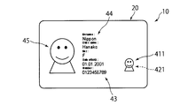
- FIG. 1 is a plan view showing an example of a personal information display that can be manufactured in an embodiment of the present invention.
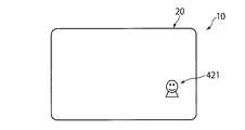
- FIG. 2 is a plan view corresponding to FIG. 1 and showing another example of the personal information display body.
- FIG. 3 is a plan view corresponding to FIG. 1 and showing the personal information display body of FIG. 2 in a state in which invisible light is irradiated.
- FIG. 4 is a diagram for explaining the layer structure of the personal information display body, and is a cross-sectional view of the personal information display body.
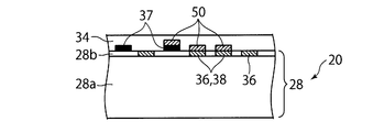
- FIG. 5 is a cross-sectional view corresponding to the partially enlarged view of FIG. 4 and schematically showing an example of a personal information display body.
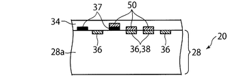
- FIG. 6 is a diagram corresponding to FIG. 5 and schematically showing another example of the personal information display body.
- FIG. 7 is a diagram corresponding to FIG. 5, schematically showing still another example of the personal information display body.
- FIG. 8 is a plan view showing an example of the diffractive optical variable element of the first display element.
- FIG. 9 is a plan view showing another example of the diffractive optical variable element of the first display element.
- FIG. 10 is a cross-sectional view corresponding to the partially enlarged view of FIG. 4 and schematically showing the first display element.
- FIG. 11 is a diagram for explaining an embodiment of the present invention, and is a diagram showing a method for manufacturing a personal information display body and a manufacturing apparatus.
- FIG. 12 is a plan view schematically showing an example of a thermal transfer sheet used in the manufacturing method of FIG. FIG.
- FIG. 13 is a diagram schematically showing a cross section taken along line XIII-XIII in FIG.
- FIG. 14 is a diagram corresponding to FIG. 12 and a plan view schematically showing another example of the thermal transfer sheet.
- FIG. 15 is a diagram corresponding to FIG. 11 and is a diagram for explaining another example of the manufacturing method and the manufacturing apparatus of the personal information display body.
- 16 is a diagram corresponding to FIG. 12 and a plan view schematically showing an example of a first thermal transfer sheet used in the manufacturing method of FIG.
- FIG. 17 is a diagram corresponding to FIG. 12 and a plan view schematically showing an example of a second thermal transfer sheet used in the manufacturing method of FIG. 15.
- FIG. 18 is a diagram corresponding to FIG.
- FIG. 17 is a plan view schematically showing a modification of the second thermal transfer sheet of FIG. 17.
- FIG. 19 is a view corresponding to FIG. 12, and is a plan view schematically showing another example of the thermal transfer sheet of FIG.
- FIG. 20 corresponds to FIG. 1 and is a plan view showing still another example of the personal information display body.
- FIG. 21 is a view corresponding to FIG. 1 and a plan view showing still another example of the personal information display body.
- FIGS. 11 to 18 are diagrams for explaining an embodiment of the present invention.
- FIGS. 11 to 18 are diagrams for mainly explaining a method and an apparatus for manufacturing a personal information display according to an embodiment of the present invention.
- FIGS. FIG. 19 is a diagram for explaining an example of a personal information display body that can be manufactured by the manufacturing method and manufacturing apparatus of FIGS. 11 to 18;
- the personal information display 10 is a medium on which personal information is recorded.
- Specific applications of the personal information display 10 can include passports, driver's licenses, health insurance cards, cash cards, credit cards, employee cards, membership cards, and the like.
- the personal information recorded on the personal information display 10 is information related to an individual, and is typically information related to a specific person who is given the personal information display 10.
- This personal information is not limited to information widely used in general society such as name, date of birth, gender, etc., but related to individuals used in connection with specific organizations such as employee numbers and membership numbers. Information, information assigned to individuals only for a certain period, and the like are also included.
- the personal information displayed by the personal information display 10 may be a part of information related to these individuals. Therefore, from the issuer of the personal information display 10, the personal information recorded on the personal information display 10 is information that must be individually handled for each personal information display 10 given to each individual. Become.
- Such a personal information display body 10 is given to the specific person as an example in order to prove the identity and qualification of the specific person.
- the issuer of the personal information display body 10 can manage the owner of the personal information display body 10 based on the information displayed on the personal information display body 10.
- a certain organization for example, a company gives a personal information display body 10, for example, an employee ID card, as a medium for proving that the organization belongs to the organization, for example, an employee of the company. .
- the organization manages entry / exit in the premises and indoors, specifically entry / exit restrictions, entry / exit records, and attendance management Etc. can be performed. Therefore, for the personal information display 10, it is easy to authenticate the owner, in other words, it is easy to determine the authenticity of the personal information display 10, and imitation and falsification are difficult. Requested.
- the personal information display body 10 has a display element for displaying personal information of a specific person to which the personal information display body 10 should be assigned.
- the first to fourth display elements 41, 42, 43, and 44 are provided on the personal information display 10, and in the other examples shown in FIGS. Fifth display elements 411, 421, 43, 44, 45 are provided on the personal information display body 10.
- the personal information display 10 is formed in a card shape.
- the personal information display 10 includes a card-like display body 20 and a cover layer 34 stacked on the display body 20.
- the display elements 41, 42, 43, 44, 45 are provided in the display body main body 20 and are positioned between the display body main body 20 and the cover layer 34 or inside the display body main body 20.
- the display body 20 before the display element is formed has a common configuration among all the personal information display bodies 10 to be issued.
- the display body 20 includes a first core layer 22 and a second core layer 23 that are stacked on each other and a first overprint printed on both sides of the core layers 22 and 23.
- a first background print layer 25 and a second background print layer 26 are printed on the surfaces of the core layers 22 and 23, respectively.
- the background print layers 25 and 26 have patterns common to the issued personal information display 10 such as a background pattern except for a special case such as a mode in which personal information is recorded by laser engraving described later. Is the printed layer.
- the oversheet layers 28 and 29 function as a protective layer.
- the second oversheet layer 29 forms the outermost surface of the card-like personal information display body 10.
- the oversheet layers 28 and 29 protect the patterns printed on the background print layers 25 and 26.
- the oversheet layers 28 and 29 may be colorless or colored in order to make the patterns printed on the background print layers 25 and 26 visible, but are preferably transparent or translucent.
- the cover layer 34 provided on the first oversheet layer 28 may be colorless or colored so that the personal information displayed by the display element and the pattern printed on the background print layer 25 can be visually recognized. It is translucent.
- Each layer constituting the display body 20 and the cover layer 34 can be produced by a known method using a known material used for a card body of an ID card, for example.
- the first oversheet layer 28 of the display body 20 that forms the surface on which the display elements 41, 42, 43, 44, 45 are formed has the display elements 41, 42 as shown in FIGS. 5 to 7.
- 43, 44, 45 can take various forms. This point will be described later in correspondence with the description of the display elements 41, 42, 43, 44, 45.
- the personal information display 10 includes display elements 41, 42, 43, 44, and 45 for displaying personal information of a specific person who should be the owner of the personal information display 10. 20 or inside the display body 20.
- the cover layer 34 laminated on the first oversheet layer 28 of the display body 20 covers the display elements 41, 42, 43, 44, 45 and protects the display elements 41, 42, 43, 44, 45.
- the first display element 41 and the second display element 42 display the upper body including the face as an image of a specific person.
- the third display element 43 displays the identification number as symbol information such as letters and numbers.
- the fourth display element 44 displays the name, gender, date of birth as character information.
- the first display element 41 is formed using the diffractive optical variable element 50.
- the diffractive optical variable element (DOVID: diffractive-optically-variable-image-device) 50 is an element that changes its observation method, for example, brightness, color, etc., depending on the observation direction by using a diffraction phenomenon.
- DOED diffractive-optically-variable-image-device
- a hologram and a diffraction grating can be exemplified.
- the diffractive optical variable element 50 formed of a hologram or a diffraction grating may be formed as a relief type or may be formed as a volume type.
- the diffractive optical variable element 50 made of a hologram or a diffraction grating may be a transmission type or a reflection type.
- the core layers 22 and 23 and the background print layers 25 and 26 may not be formed transparently.
- the diffractive optical variable element 50 may be opaque, or may be transparent or translucent regardless of color or colorless.
- the diffractive optical variable element 50 is provided on the first oversheet layer 28 of the display body 20 via the bonding layer 56.
- the diffractive optical variable element 50 is configured as a relief type computer-generated hologram or diffraction grating.
- the diffractive optical variable element 50 includes a concavo-convex forming layer 52 having a concavo-convex surface and a reflective layer 54 covering the concavo-convex surface of the concavo-convex forming layer 52.
- the unevenness forming layer 52 is formed using, for example, a transparent resin.
- the reflective layer 54 can be formed as a thin film deposited on the concavo-convex surface of the concavo-convex forming layer 52.
- the reflective layer 54 can be formed using a metal-containing material having a refractive index different from that of the unevenness forming layer 52, such as titanium oxide, zinc sulfide, and tin oxide.
- the reflective layer 54 does not need to be opaque, and may be transparent or translucent.
- the first display element 41 displays personal information according to the arrangement pattern of the diffractive optical variable element 50. For example, by transferring the sheet-like diffractive optical variable element 50 in a desired arrangement pattern, the first display element 41 can display personal information grasped depending on the arrangement pattern of the diffractive optical variable element 50. it can. In other words, according to the personal information display 10 described here, the first display element 41 has the specific information of the specific person, typically, depending on the arrangement pattern of the diffractive optical variable element 50 that requires advanced manufacturing technology. The personal information of the owner of the personal information display body 10 is displayed. Thus, since the 1st display element 41 is formed using the diffractive optical variable element 50, forgery of the personal information display body 10 can be made difficult.
- the personal information display 10 since it is only necessary to display the personal information in the arrangement pattern of the diffractive optical variable element 50, it is not necessary to record the personal information on the diffractive optical variable element 50 itself, for example, as an uneven structure or interference fringes. Therefore, the personal information display 10 can be manufactured relatively easily and can exhibit excellent anti-counterfeiting properties.
- the first display element 41 displays an image of a specific person who should be the owner of the personal information display body 10 by the arrangement pattern of the diffractive optical variable element 50.
- an image of the owner particularly a face
- the authentication of the owner and the authenticity determination of the personal information display body 10 based on the authentication result can be easily and accurately performed.
- the first display element 41 displays the image of the owner, particularly the face, by the arrangement pattern of the diffractive optical variable element 50 that requires advanced manufacturing techniques. Therefore, the personal information display body 10 that can be manufactured relatively easily can be provided with extremely excellent anti-counterfeiting properties, and the authentication of the owner using the personal information display body 10 and the personal information The authenticity determination of the display body 10 can be performed very easily and accurately.
- the diffractive optical variable element 50 itself has a pattern that does not display personal information.
- the pattern possessed by the diffractive optical variable element 50 itself is not limited to the one showing specific information or meaning the specific information, and is not particularly limited to the arrangement of figures, characters, symbols, marks and the like, the pattern, the pattern and the like. That is, the diffractive optical variable element 50 can display the personal information of a specific person according to the arrangement pattern, but the diffractive optical variable element 50 itself may display a pattern unrelated to the personal information. . Therefore, the pattern possessed by the diffractive optical variable element 50 itself is common to all the issued personal information display bodies 10 irrespective of the personal information to be displayed using the diffractive optical variable element 50. Can do. Thereby, the personal information display body 10 can be produced more easily.
- a minute concealment image can be included in a pattern unrelated to personal information displayed by the diffractive optical variable element 50 itself.
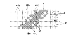
- the diffractive optical variable element 50 has a gradation of binary or higher for each of the plurality of unit regions 48 defined on the surface on which the first display element 41 is to be provided.
- the first display element 41 is formed as an aggregate of diffractive optical variable elements 50 arranged in the predetermined unit region 48.
- the plurality of unit regions 48 are divided into two types: a region where the diffractive optical variable element 50 is disposed and a region where the diffractive optical variable element 50 is not disposed. Is done.
- the surface on which the first display element 41 is to be provided for example, the surface of the display body 20 in FIGS. 5 to 7 is divided into a matrix and arranged in a grid adjacent to each other.
- a plurality of unit regions 48 are defined. According to this embodiment, personal information can be displayed with excellent design by the first display element 41 using the diffractive optical variable element 50.
- the first display element 41 can clearly display an image of the owner of the personal information display body, particularly a face image, in many gradations.
- the personal information display body 10 that can be manufactured relatively easily can be provided with a better anti-counterfeit property, and the personal information display body 10 can be authenticated and the personal information display can be performed.
- the authenticity determination of the body 10 can be performed very easily and more accurately.
- various known methods such as dithering can be employed as a method for realizing gradations having more than binary values.
- the unit area 48 is divided into four sub-unit areas 49. Whether or not the diffractive optical variable element 50 is arranged is determined for each sub-unit region 49.
- the plurality of unit regions 48 include a zero-stage region 48 a in which none of the four sub-unit regions 49 is provided with the diffractive optical variable element 50 and four sub-unit regions 49.
- the diffractive optical variable element 50 is provided in the one-stage region 48b in which the diffractive optical variable element 50 is provided only in one of the sub unit regions 49, and the two sub unit regions 49 of the four sub unit regions 49.
- the two-stage region 48c, the three-stage region 48d in which the diffractive optical variable element 50 is provided in three of the four subunit regions 49, and the four subunit regions 49 are diffracted.
- the first display element 41 is formed as a collection of diffractive optical variable elements 50 arranged in each of the plurality of unit regions 48 with a five-value area gradation.
- the personal information is displayed by the arrangement pattern of the aggregate of the diffractive optical variable elements 50 arranged in the area gradation.
- the first display element 41 as an aggregate of the diffractive optical variable elements 50 arranged in the unit region 48 is obtained by attaching the diffractive optical variable element 50 formed in a sheet shape to the unit region 48 using an adhesive or the like. It can be produced by transferring. Typically, as will be described in detail later, the first display element 41 can be manufactured by thermal transfer using the thermal heads 62 and 67.
- the arrangement of the diffractive optical variable elements 50 in each unit region 48 is controlled, and the human face is displayed by the controlled arrangement pattern of the diffractive optical variable elements 50.
- the face is displayed as a so-called ghost image separately from the face displayed by the second display element 42 as in the example shown in FIG.
- the length of one side of the unit region 48 is preferably 20 ⁇ m or more and 300 ⁇ m or less. Transfer of the diffractive optical variable element 50 to the unit region 48 having such a size can be sufficiently realized by thermal transfer using a thermal head incorporated in a thermal transfer printer.
- the second to fourth display elements 42 to 44 Similarly to the first display element 41, the second to fourth display elements 42 to 44 display personal information of a specific person who should own the personal information display body 10. As already described, in the personal information display 10 shown in FIG. 1, the third display element 43 displays the identification number as symbol information such as letters and numbers. The fourth display element 44 displays the name, sex, date of birth as character information. Similar to the first display element 41, the second display element 42 displays the upper body including the face of a specific person who should own the personal information display body 10. However, the second to fourth display elements 42 to 44 are formed without using a diffractive optical variable element. In other words, the second to fourth display elements 42 to 44 are different from the first display element 41 in at least one of the material used and the forming method.
- the personal information display body 10 includes a plurality of display elements which are different in at least one of the material and the forming method, the forgery prevention property of the personal information display body 10 can be effectively enhanced.
- the first display element 41 and the second display element 42 which are different in at least one of the material and the forming method both display the same personal information.
- the displayed personal information is an image of a person that facilitates authentication, and the first display element 41 as one display element exhibits excellent anti-counterfeiting properties as described above.
- the personal information display 10 first, based on a clear image displayed by the second display element 42, authentication of the owner of the personal information display 10 and authentication of the personal information display 10 are performed.
- the determination can be made more easily and accurately.
- the authenticity determination of the personal information display body 10 can be performed more accurately.
- the personal information display body 10 has better anti-counterfeiting properties.
- the second to fourth display elements 42 to 44 can be produced by various known methods.
- the second to fourth display elements 42 to 44 can be formed on the display body 20 by transferring the coloring material to the first oversheet layer 28 of the display body 20 by sublimation heat transfer printing. it can.
- the color material thermally transferred to the display body 20 can include various colors corresponding to the second to fourth display elements 42 to 44 to be manufactured.
- the personal information display 10 for displaying personal information by a full-color image four color materials of yellow, magenta, cyan, and black, or four color materials of red, green, blue, and black are used. Will be thermally transferred.
- the diffractive optical variable element 50 and one or more of yellow, magenta, and cyan color materials, or one or more of red, green, and blue materials are formed between the display body 20 and the cover layer 34.
- a color layer 36 and a black layer 37 made of black are formed.
- the second to fourth display elements 42 to 44 are formed from a color layer 36 and a black layer 37 provided on the display body 20 by thermal transfer printing.
- the first oversheet layer 28 of the display body 20 to which the color material is transferred includes a body layer 28a made of, for example, polyethylene terephthalate (PET) or polycarbonate (PC).
- the color layer 36 is formed in the receiving layer 28b, and the black layer 37 and the diffractive optical variable element 50 are formed on the surface of the receiving layer 28b.
- the first oversheet layer 28 to which the color material is transferred is a single material that can receive a dye that forms a color color material such as polychlorinated chloride (PVC). It is formed as a layer. Therefore, in the personal information display body 10 shown in FIG. 6, the color layer 36 is formed in the surface layer of the first oversheet layer 28, and the black layer 37 and the diffractive optical variable element are formed on the surface of the first oversheet layer 28. 50 is formed.
- PVC polychlorinated chloride
- the first oversheet layer 28 includes a main body layer 28 a that functions as a support material, and a laser coloring layer 28 c and a receiving layer 28 b that are sequentially stacked on the main body layer 28 a. Yes. A color material can be transferred to the receiving layer 28b by thermal transfer printing. Then, a black layer 37 along the scanning path of the laser light can be formed on the laser coloring layer 28c by irradiating the laser coloring layer 28c with a laser beam in a wavelength range in which the laser coloring layer 28c exhibits sensitivity.
- the first background print layer 25 of the display body 20 is formed as a laser coloring layer, and personal information is recorded on the first background print layer 25 of the display body 20 by a laser engraving method. You may make it do.
- the personal information display body 10 has been described based on the example shown in FIG. 1, the personal information display body 10 shown in FIG. 1 can be manufactured according to the present embodiment.
- the second to fourth display elements 42 to 44 may display personal information different from the example described above.
- other display elements may be provided in the personal information display body 10.
- the personal information display body 10 shown in FIGS. 2 and 3 has first to fifth display elements 411, 421, 43, 44, 45.
- the first display element 411, the third display element 43, and the fourth display element 44 of the personal information display body 10 shown in FIGS. 2 and 3 are respectively the personal information display body 10 shown in FIG.
- the first display element 41, the third display element 43, and the fourth display element 44 are the same.
- the fifth display element 45 of the personal information display 10 shown in FIGS. 2 and 3 is the same as the second display element 42 of the personal information display 10 shown in FIG.
- Each part of the personal information display 10 shown in FIGS. 2 and 3 is the same as the corresponding part of the personal information display 10 shown in FIG. 1 except for the second display element 421 described in detail below. It can be configured identically.
- the second display element 421 displays the personal information of a specific person who should own the personal information display body 10, similarly to the first display element 411. More specifically, like the first display element 411, the second display element 421 displays the upper body including the face of a specific person who should own the personal information display body 10. In particular, in the example shown in FIGS. 2 and 3, the image displayed by the second display element 421 displays the same image as the image displayed by the first display element 411 with the same size. Further, the image displayed by the first display element 411 and the image displayed by the second display element 421 overlap at the same position along the surface direction of the personal information display surface of the personal information display body 10. Is arranged.
- Forgery of the personal information display body 10 can be effectively made difficult by arranging the first display element 411 and the second display element 421 manufactured by different methods at least partially overlapping each other.
- the first display element 411 exhibits excellent anti-counterfeiting alone, as described above, and the first display element 411 has the first display element 411.
- the image and the image of the second display element 421 overlap and are observed. For this reason, forgery of the personal information display body 10 can be made extremely difficult.
- the first display element 411 and the second display element 421 can display the same personal information at the same position, the personal information displayed by the first display element 411 and the second display element 421 are displayed. It becomes possible to more accurately determine the authenticity of the personal information display body by comparison with the personal information to be displayed.
- the first display element 411 and the second display element 421 is formed to be transparent or translucent.
- the first display element 411 is arranged on the surface side of the personal information display body 10, that is, the viewer side, and is formed to be transparent or translucent as described above, and the second display element 421 is the first display element.
- the second display element 421 may be formed using a fluorescent material.
- the fluorescent light emitting material is a material that exhibits sensitivity to light in a certain wavelength range and emits light when receiving light in the wavelength range. According to such a personal information display 10, personal information displayed by the second display element 421 can be observed under special conditions. Under normal conditions, the second display element 421 It is possible to prevent the displayed personal information from being visually recognized.
- the second display element 421 may be manufactured using a fluorescent material that emits visible light when irradiated with invisible light such as infrared rays or ultraviolet rays.
- a fluorescent material that emits visible light when irradiated with invisible light such as infrared rays or ultraviolet rays.
- the forgery prevention property of the personal information display 10 can be greatly improved.
- the image displayed by the first display element 411 can be observed more accurately under normal conditions, the owner can be authenticated and the authenticity determination of the personal information display can be performed more accurately.
- the second display element 421 under a special environment where only the fluorescent light emitting material is irradiated with sensitive invisible light, only personal information displayed by the second display element 421 is observed as shown in FIG. . Thereby, the authentication of the owner and the authenticity determination of the personal information display body 10 can be easily and accurately performed also by the personal information image displayed by the second display element 421.
- the second display element 421 can be manufactured by various known methods.
- the second display element 421 can be provided on the surface layer of the display body 20 or on the display body 20 by thermally transferring the fluorescent material to the first oversheet layer 28 by a thermal transfer printing method.
- the fluorescent color-developing layer 38 shown in FIGS. 5 to 7 may be formed using the described fluorescent light-emitting material.
- the manufacturing method of the personal information display described here includes the step of preparing the display body 20 and the diffractive optical variable element region 85 of the thermal transfer sheet 80 so as to face the display body 20 to display personal information.
- the diffractive optical variable element 50 By transferring the diffractive optical variable element 50 to the display body main body 20 in the obtained arrangement pattern, the color material is displayed in the process of providing the first display element 41 on the display body main body 20 and the arrangement pattern capable of displaying personal information. And transferring the second to fourth display elements 42 to 44 to the display body main body 20 by transferring them to the body main body 20.
- the personal information display manufacturing apparatus 60 arranges the diffractive optical variable element region 85 of the transfer sheet 80 so as to face the display body 20 and can display personal information.
- the transfer device 61 for transferring the diffractive optical variable element 50 to the display body main body 20 is provided, and the first display element 41 is provided on the display body main body 20 by the transfer device 61.
- the display body 20 can be manufactured by a known method. Specifically, the background printing layers 25 and 26 are printed on the core layers 22 and 23 described above, respectively, and a plurality of sheet-like materials that form the oversheet layers 28 and 29 are stacked on each other, thereby laminating. Create a body. Then, the display body 20 is obtained by cutting the obtained laminated body into a desired size. In addition, it is preferable from a viewpoint of production efficiency that the laminated body, which is an intermediate when the display body 20 is manufactured, is formed in such a size that a plurality of display bodies 20 having a desired size can be taken out.
- the transfer device 61 will be described in detail.
- the second to fourth display elements 42 to 44 are provided in the display body 20 by transferring the color material to the display body 20 by thermal transfer printing.
- the first display element 41 is provided in the display body 20 by transferring the diffractive optical variable element 50 to the display body 20 in a desired arrangement pattern by thermal transfer printing.
- the transfer device 61 is configured as a thermal transfer device having a thermal head 62.
- the thermal transfer device 61 is configured as a so-called thermal transfer printer.
- the thermal transfer device 61 heats a support means 63 that supports a display body 20 as a transfer target, and a thermal transfer sheet 80 that is disposed on the support means 63 at a position facing the display body 20.
- a thermal head 62 that pressurizes, a thermal transfer sheet supply unit 64 that can supply the thermal transfer sheet 80 so that the diffractive optical variable element region 85 or the color material regions 81 to 84 face the display body 20 on the support unit 63; have.
- the thermal transfer sheet supply means 64 has a feed roll 64a for feeding out the thermal transfer sheet 80 and a recovery roll 64b for collecting the thermal transfer sheet 80 after the thermal transfer.
- the thermal transfer sheet 80 fed from the feed roll 64a passes between the thermal head 62 and the support means 63 and is collected by the collection roll 64b.
- the display body 20 is supplied one by one from a display body supply means (not shown).
- the support means 63 is formed as a support table that supports a single card-like display body 20.
- FIG. 12 shows an example of the thermal transfer sheet 80 supplied from the thermal transfer sheet supply means 64.
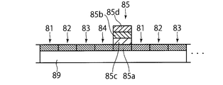
- the illustrated thermal transfer sheet 80 includes a long base sheet 89 and a color material region 81 including a color material for forming the second to fourth display elements 42 to 44 provided on the base sheet 89. , 82, 83, 84, a diffractive optical variable element region 85 for forming the first display element 41, and a cover layer region 86 for forming the cover layer 34.
- a color material region including a color material a yellow region 81 including a yellow dye as a color material, a magenta region 82 including a magenta dye as a color material, and a cyan dye are used.
- a cyan region 83 including a color material and a black region 84 including a black color material are provided. As shown in FIGS. 12 and 13, a yellow region 81, a magenta region 82, a cyan region 83, a black region 84, a diffractive optical variable element region 85, and a cover layer region 86 are repeatedly arranged on the base sheet 89. Has been. However, the color material region included in the thermal transfer sheet 80 can be changed as appropriate in accordance with the display elements of the personal information display body 10 to be manufactured.
- the release layer 85a, the concavo-convex formation layer 85b, the reflection layer 85c, and the heat seal layer 85d are sequentially arranged from the base sheet 89 side. Are stacked on the base sheet 89.
- the thermal head 62 contacts the base sheet 89 and presses the heat seal layer 85 d against the display body 20. Then, the heat seal layer 85d forms the bonding layer 56 of the personal information display body 10 shown in FIG.
- the reflective layer 85c of the thermal transfer sheet 80 forms the reflective layer 54 of the personal information display body 10 shown in FIG.
- the concave / convex forming layer 85b of the thermal transfer sheet 80 becomes the personal information display shown in FIG.
- the unevenness forming layer 52 of the body 10 is formed. That is, in the illustrated thermal transfer sheet 80, the reflective layer 85 c and the unevenness forming layer 85 b form a diffractive optical variable element layer including the diffractive optical variable element 50 that forms the first display element 41.
- the peeling layer 85a is a layer which has peelability with respect to the adjacent uneven
- the diffractive optical variable element 50 can be formed of various elements whose manner of observation, for example, brightness, color, etc., changes depending on the observation direction by using the diffraction phenomenon.
- the configuration of the diffractive optical variable element region 85 of the thermal transfer sheet 80, in particular, the concavo-convex forming layer 85b and the reflective layer 85c of the diffractive optical variable element region 85 of the diffractive optical variable element 50 to be transferred onto the display body 20 It can change suitably according to a structure.
- the diffractive optical variable element region 85 of the thermal transfer sheet 80 may include a transmissive hologram or diffraction grating, or may include a volume hologram or diffraction grating.
- a release layer 86a, a protective layer 86b, an ultraviolet absorbing layer 86c, and a heat seal layer 86d are sequentially formed from the base sheet 89 side. It is overlaid on the base material sheet 89.
- the cover layer region 86 comes into contact with the display body 20 from the heat seal layer 86 d side when the thermal head 62 contacts the base sheet 89.
- the cover layer 34 of the personal information display body 10 shown in FIG. 10 is formed using the thermal transfer sheet 80, the cover layer 34 includes a heat seal layer 86d, an ultraviolet absorbing layer 86c, and a protective layer 86b.
- the protective layer 86b is a layer that forms the outermost surface of the personal information display body 10, and preferably has transparency, scratch resistance, and the like.
- the ultraviolet absorbing layer 86c is a layer located inside the protective layer 86b, that is, on the diffractive optical variable element 50 side in the personal information display body 10, and absorbs ultraviolet rays. Thereby, it can prevent effectively that the display elements 41, 42, and 43 of the personal information display body 10 located inside the ultraviolet absorption layer 86c are deteriorated by ultraviolet rays.
- the ultraviolet absorbing layer 86c can be omitted as necessary.
- the personal information display manufacturing apparatus 60 of the present embodiment includes a recording means 65 for recording the personal information of a specific person.
- the recording unit 65 records an image of a specific person corresponding to the personal information displayed by the first display element 41 and the second display element 42 as an image, or the personal information displayed by the third display element 43. Is recorded as symbol information such as letters and numbers, and the name, gender, and date of birth corresponding to the personal information displayed by the fourth display element 44 are recorded as character information.
- the first display element 41 and the second display element 42 display the upper body including the face based on the same image recorded in the recording means 65. According to such a recording unit 65, the first display element 41 and the second display element 42 can be produced based on one piece of personal information recorded in the recording unit 65.
- the display elements 41, 42, 43, and 44 and the cover layer 34 are formed on the display body 20 as follows.
- the display body 20 to be processed next is supplied onto the support means 63.
- the thermal transfer sheet 80 is supplied between the thermal head 62 and the support means 63 by the thermal transfer sheet supply means 64 in accordance with the supply of the display body 20.
- the thermal transfer sheet 80 is positioned so that the yellow area 81 faces the display body 20 on the support means 63. In this state, based on the personal information recorded in the recording means 65, the thermal head 62 sublimates and transfers the yellow dye in the yellow region 81 to the display body 20 in an arrangement pattern capable of displaying the personal information. .
- the thermal transfer sheet 80 is conveyed, and the magenta area 82 located next to the yellow area 81 where the thermal transfer process is completed faces the display body 20. become.
- the thermal head 62 performs sublimation thermal transfer of the magenta dye in the magenta region 82 to the display body 20 in an arrangement pattern capable of displaying the personal information based on the personal information recorded in the recording unit 65.
- the cyan dye and the black color material in the cyan region 83 are thermally transferred to the display body 20 in a pattern capable of displaying personal information.
- the color layer 36 and the black layer 37 are formed on the display body 20.
- the thermal transfer sheet 80 is conveyed so that the diffractive optical variable element region 85 of the thermal transfer sheet 80 faces the display body 20 on the support means 63.
- the diffractive optical variable element 50 is arranged with a gradation of binary or higher for each of the plurality of unit regions 48 virtually defined on the display body 20.
- the thermal head 62 corresponds to the thermal transfer sheet 80 so that the diffractive optical variable element region 85 of the thermal transfer sheet 80 contacts the predetermined unit region 48 among the many unit regions 48. Push in the heating position. Due to the heating from the thermal head 62, the heat seal layer 85d of the diffractive optical variable element region 85 has adhesiveness at a position where it abuts on the display body 20.
- the unevenness forming layer 85b is peeled off from the release layer 85a having releasability, and the reflective layer 85c and the unevenness forming layer 85b are removed from the base sheet 89 of the thermal transfer sheet 80 via the heat seal layer 85d. Transcribed above. In this way, the diffractive optical variable element 50 including the reflective layer 85c and the unevenness forming layer 85b is thermally transferred onto the display body 20. Finally, based on the personal information recorded in the recording means 65, the diffractive optics is variable on the display body 20 in an arrangement pattern capable of displaying the personal information of the specific person to whom the personal information display body 10 is to be given. An element 50 is provided. As described above, the first display element 41 including the diffractive optical variable element 50 is formed on the display body 20.
- the thermal transfer sheet 80 is conveyed, and the cover layer region 86 of the thermal transfer sheet 80 faces the display body 20 on the support means 63.
- the cover layer region 86 is transferred to the entire area on the display body 20 by heat and pressure from the thermal head 62. Accordingly, the first to fourth display elements 41 to 44 provided in the display body 20 are covered with the cover layer 34 composed of the ultraviolet absorbing layer 86c and the protective layer 86b joined via the heat seal layer 86d. Become.
- the personal information of a specific person is displayed by the arrangement pattern of the diffractive optical variable element 50 that requires advanced manufacturing technology.
- the personal information display 10 including the display element 41 can be manufactured relatively easily.
- the first display element 41 is formed using the diffractive optical variable element 50, which makes it difficult to forge the personal information display 10. it can.
- personal information only needs to be displayed in the arrangement pattern of the diffractive optical variable element 50, so that there is no need to record the personal information on the diffractive optical variable element 50 itself, for example, as an uneven structure or interference fringes. Therefore, according to the manufacturing method and manufacturing apparatus of the present embodiment, the personal information display 10 having excellent anti-counterfeiting properties can be manufactured relatively easily.
- the thermal transfer sheet 80 is heated and pressurized using the thermal head 62, whereby the diffractive optics can be varied in an arrangement pattern that can display personal information.
- the element 50 is thermally transferred to the display body 20.
- the diffractive optical variable element 50 can be thermally transferred to each display body 20 in different arrangement patterns that can display desired personal information.
- one thermal transfer sheet 80 is used for the first display element 41, the second display element 42, the third display element 43, and the fourth display of one personal information display body 10.
- the diffractive optical variable element region 85 and the color material regions 81 to 84 for forming the element 44 and the cover layer 34 are all included. Therefore, the first display element 41, the second display element 42, the third display element 43, and the fourth display element 44 can be accurately positioned with respect to each other.
- the first display element 41 displays an image of a specific person by the arrangement pattern of the diffractive optical variable element 50. indicate.
- an image of the owner particularly a face
- the authentication of the owner and the authentication of the personal information display body 10 based on the authentication result can be easily and accurately performed. it can.
- the first display element 41 displays the image of the owner, particularly the face, according to the arrangement pattern of the diffractive optical variable element 50 that requires advanced manufacturing technology. Therefore, according to the personal information display 10 of FIG. 1, the personal information display 10 that can be manufactured relatively easily can be provided with extremely excellent anti-counterfeiting properties, and the personal information display 10 10 can be used to authenticate the owner and to determine the authenticity of the personal information display 10 very easily and accurately.
- the above manufacturing method is merely an example, and various modifications are possible.
- the first display element 41, the second display element 42, the third display element 43, the fourth display element 44, and the cover layer 34 are formed on the display body 20 by thermal transfer.
- An example is shown, but the present invention is not limited to this.
- the first display element 41, the second display element 42, the third display element 43, and the fourth display element 44 are formed by thermal transfer on the cover layer 34 that is supplied so as to face the thermal head 62. Even when the cover layer 34 on which the first display element 41, the second display element 42, the third display element 43, and the fourth display element 44 are formed is laminated on the display body main body 20, the personal information display body 10 is produced. Good.
- the yellow region 81, the magenta region 82, the cyan region 83, the black region 84, and the diffractive optical variable element region 85 are repeatedly arranged on the base sheet 89 of the thermal transfer sheet 80.
- the In the diffractive optical variable element region 85, the peeling layer 85 a, the reflective layer 85 c, the unevenness forming layer 85 b, and the heat seal layer 85 d are stacked on the base sheet 89 in order from the base sheet 89 side.
- the receiving layer 28b capable of receiving the dye may be thermally transferred onto the display body 20 prior to sublimation thermal transfer of the coloring material containing the dye.
- the thermal transfer sheet 80 may have an area including the receiving layer between the cover layer area 86 and the yellow area 81.
- each region included in the thermal transfer sheet 80 can be changed as appropriate in accordance with the configuration of the display element to be formed on the display body 20.
- a second display element 421 using a fluorescent material is provided on the display body 20. Therefore, as shown in FIG. 14, if the thermal transfer sheet 80 further includes a fluorescent light emitting material region 88 containing a fluorescent light emitting material, the second information of the personal information display body 10 shown in FIG. 2 and FIG.
- the display element 421 can be formed on the display body 20 by thermal transfer.
- the diffractive optical variable element region 85 for forming the first display element 411 and the fluorescent light emitting material region 88 for forming the second display element 421 are the same base. Since they are arranged side by side on the material sheet 89, the first display element 411 and the second display element 421 can be aligned with respect to each other with high accuracy. Thereby, the personal information display body 10 including the first display element 411 and the second display element 421 that display the same image at the same position can be manufactured relatively easily without difficulty.
- FIG. 16 shows a first thermal transfer sheet 80a in which a yellow region 81, a magenta region 82, a cyan region 83, and a black region 84 are repeatedly formed in order on a base sheet 89.
- a first thermal transfer sheet 80a is widely used in normal sublimation thermal transfer printing without being limited to application to the personal information display 10, and is available at low cost.
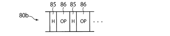
- FIG. 17 shows a second thermal transfer sheet 80 b in which a diffractive optical variable element region 85 and a cover layer region 86 are repeatedly formed in order on a base sheet 89.
- the personal information display body manufacturing apparatus 60 is arranged downstream of the thermal transfer apparatus 61 along the transport direction of the display body 20 in addition to the thermal transfer apparatus 61 described above.
- a second thermal transfer device 66 is further provided.
- the second thermal transfer device 66 can be composed of a thermal transfer printer similar to the thermal transfer device 61.
- the thermal transfer sheet supply means 64 of the thermal transfer device 61 supplies the first thermal transfer sheet 80a. Therefore, the thermal transfer device 61 forms the color layer 36 and the black layer 37 on the display body 20.
- the second thermal transfer device 66 includes a second thermal transfer sheet supply unit 69 that supplies the second thermal transfer sheet 80b, and a second support unit 68 that supports the display body 20 on which the color layer 36 and the black layer 37 are formed. And a second thermal head 67 that heats and presses the second thermal transfer sheet 80b toward the display body 20 on the second support means 68.
- the second thermal transfer sheet supply means 69 has a feed roll 69a for feeding out the second thermal transfer sheet 80b and a recovery roll 69b for collecting the second thermal transfer sheet 80b after the thermal transfer.
- the second thermal transfer sheet 80b fed from the feed roll 69a passes between the second thermal head 67 and the second support means 68 and is collected by the collection roll 69b.
- the display body 20 is supplied to the first thermal transfer device 61 one by one from a display body supply means (not shown). Then, in the first thermal transfer device 61, the color layer 36 and the black layer 37 are thermally transferred to the display body 20. The display body 20 on which the color layer 36 and the black layer 37 are formed is then transported to the second thermal transfer device 66, where the diffractive optical variable element 50 and the cover layer 34 are placed on the display body 20. Thermally transferred.
- the area where the diffractive optical variable element 50 is transferred on the display body 20 is small. Therefore, as shown in FIG. 18 as an example, the size of the diffractive optical variable element region 85 in the thermal transfer sheet 80 and the second thermal transfer sheet 80b is small considering the size of the diffractive optical variable element 50 to be transferred. May be used. In this case, the cost of the thermal transfer sheet 80 and the second thermal transfer sheet 80b can be effectively reduced. In connection with this, the manufacturing cost of the personal information display body 10 can be reduced effectively.
- the manufacturing method and manufacturing apparatus of the personal information display 10 in addition to the personal information display 10 shown in FIGS. 1 to 3, for example, as shown in FIG. 20 and FIG.
- the personal information display 10 to be manufactured can also be manufactured.
- 20 and 21 are views corresponding to FIG. 1 and are plan views showing still other examples of the personal information display body.
- the personal information display body 10 shown in FIG. 20 has first to fourth and sixth display elements 412, 422, 43, 44, 46.
- the second to fourth display elements 422, 43, and 44 of the personal information display body 10 shown in FIG. 20 are the second to fourth display elements of the personal information display body 10 shown in FIG. 1, respectively. 42 to 44 may be configured identically.
- Each part of the personal information display 10 shown in FIG. 20 has the same configuration as the corresponding part of the personal information display 10 shown in FIG. 1 except for the first display element 412 described in detail below. can do.
- the first display element 412 displays the identification number as symbol information such as letters and numbers according to the arrangement pattern of the diffractive optical variable element 50.
- the first display element 412 is arranged at a position at least partially overlapping the second display element 422 along the surface direction of the personal information display surface of the personal information display body 10. Since the first display element 412 and the second display element 422 manufactured by different methods are at least partially overlapped, forgery of the personal information display body 10 can be effectively made difficult.
- the first display element 412 exhibits excellent anti-counterfeiting properties alone, as well as the image of the first display element 412 and the first display element 412. 2
- the image of the display element 422 overlaps and is observed. For this reason, forgery of the personal information display body 10 can be made extremely difficult.
- the sixth display element 46 displays the same image as that displayed by the second display element 422 in the same size or a different size. However, the sixth display element 46 is preferably formed on the display body 20 by a method different from that of the second display element 422. By providing the sixth display element 46 in the personal information display body 10 in addition to the second display element 422, the forgery prevention property of the personal information display body 10 can be effectively improved. In the example shown in FIG. 20, the sixth display element 46 and the first display element 41 in FIG.
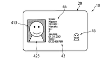
- the personal information display body 10 shown in FIG. 21 has first to fourth and sixth display elements 413, 423, 43, 44, and 46.
- the second to fourth display elements 423, 43, and 44 of the personal information display 10 shown in FIG. 21 are the second to fourth display elements of the personal information display 10 shown in FIG. 1, respectively. 42 to 44 may be configured identically.
- the sixth display element 46 of the personal information display body 10 shown in FIG. 21 may be configured the same as the sixth display element 46 of the personal information display body 10 shown in FIG.
- Each part of the personal information display 10 shown in FIG. 21 is the same as the corresponding part of the personal information display 10 shown in FIG. 1 or 20 except for the first display element 413 described in detail below. It can be configured identically.
- the first display element 413 displays the personal information as a negative depending on the arrangement pattern of the diffractive optical variable element 50.
- “displaying personal information in a negative manner according to the arrangement pattern of the diffractive optical variable element 50” means displaying the information in reverse, in other words, adjacent to the region where the diffractive optical variable element 50 is disposed. It represents a symbol or image indicating personal information in an area. According to such a form, even if the region where the diffractive optical variable element 50 is disposed does not represent personal information, by expressing a symbol or image indicating personal information in a region adjacent to the region, The first display element 413 can display personal information.
- the first display element 413 shown in FIG. 21 displays the background of the image of the specific person displayed by the second display element 423.
- At least a part of the outer contour of the arrangement pattern of the first display element 413 extends along at least a part of the outer contour of the second display element 423.
- at least a part of the outline of the first display element 413 and at least a part of the outline of the second display element 423 have complementary shapes that are related to each other. Since the first display element 413 and the second display element 423 manufactured by different methods extend at least partially along the outer contour of each other, it is difficult to effectively counterfeit the personal information display body 10. can do.
- the first display element 413 is displayed by the first display element 413 in addition to exhibiting excellent anti-counterfeiting properties alone as described above.
- the personal information and the personal information displayed by the second display element 423 are observed in association with each other. For this reason, forgery of the personal information display body 10 can be made extremely difficult.
Landscapes
- Physics & Mathematics (AREA)
- General Physics & Mathematics (AREA)
- Optics & Photonics (AREA)
- Credit Cards Or The Like (AREA)
- Diffracting Gratings Or Hologram Optical Elements (AREA)
Abstract
個人情報表示体(10)には、個人情報が記録される。個人情報表示体(10)の製造方法は、熱転写シート(80)の回折光学可変素子領域(85)を表示体本体(20)と対向するよう配置し、個人情報を表示し得る配置パターンにて回折光学可変素子領域(85)に含まれる回折光学可変素子(50)を表示体本体(20)に転写することによって、回折光学可変素子(50)を含み個人情報を表示する第1表示要素(41)を表示体本体(20)に設ける工程を備える。
Description
本発明は、個人情報が記録された個人情報表示体の製造方法および製造装置に関する。
所有者の身元や資格等を証明するための媒体として、当該所有者の情報を記録した個人情報表示体が広く利用されてきた。個人情報表示体として、パスポート、運転免許証、健康保険証、キャッシュカード、クレジットカード、社員証、会員証等が例示される。例えばJP2006-103221Aにも開示されているように、このような個人情報表示体に対しては、その用途に対応して、真贋の判定が容易であることのほか、効果的に偽造を防止し得ることが要望される。このような要望に応えるべく、ホログラムや回折格子に代表される回折光学可変素子を、個人情報表示体に設けることも検討されてきた。回折光学可変素子は、単なるカラーコピー等によって容易に複製され得ず、その製造に高度な製造技術が必要とされるからである。
しかしながら、個別の情報を表示する回折光学可変素子を各人に付与される個人情報表示体毎に作製することは困難である。また、個人情報表示体の発行に長期間を要することになる。このため、現状ではクレジットカードに代表されるように、個人情報表示体に設けられた回折光学可変素子は共通の情報や模様等を表示するにとどまっている。
本発明は以上の点を考慮してなされたものであり、偽造が困難である個人情報表示体を比較的に容易に製造することができる製造方法および製造装置を提供することを目的とする。
本発明による個人情報表示体の製造方法は、表示体本体を準備する工程と、回折光学可変素子を含んだ回折光学可変素子領域を有する転写シートの当該回折光学可変素子領域を表示体本体と対向するよう配置し、個人情報を表示し得る配置パターンにて前記回折光学可変素子を前記表示体本体に転写することによって、回折光学可変素子を含み個人情報を表示する第1表示要素を前記表示体本体に設ける工程と、を備える。
前記第1表示要素を前記表示体本体に設ける工程において、サーマルヘッドを用いて前記転写シートを加熱加圧することにより、個人情報を表示し得る配置パターンにて前記回折光学可変素子を前記表示体本体に熱転写してもよい。
本発明による個人情報表示体の製造方法は、個人情報を表示し得る配置パターンにて色材を前記表示体本体に転写することによって、前記色材を含み個人情報を表示する第2表示要素を前記表示体本体に設ける工程をさらに備えてもよい。
前記転写シートは、前記色材を含む色材領域を有しており、前記第2表示要素を前記表示体本体に設ける工程において、前記色材領域を前記表示体本体と対向するよう配置し、サーマルヘッドを用いて前記転写シートを加熱加圧することにより、個人情報を表示し得る配置パターンにて前記色材を前記表示体本体に熱転写してもよい。
前記第1表示要素を前記表示体本体に設ける工程において、前記表示体本体に画成される複数の単位領域のそれぞれに対して三値以上の階調で前記回折光学可変素子を配置してもよい。
本発明による個人情報表示体の製造方法は、レーザーエングレービングにより、前記表示体本体のレーザー発色層に、個人情報を表示する更なる表示要素を設ける工程を更に備えてもよい。
なお、第1表示要素を表示体本体に設ける工程と、第2表示要素を表示体本体に設ける工程と、更なる表示要素を設ける工程とが、実施される順番は特に限定されない。例えば、更なる表示要素を設ける工程が、第1表示要素を表示体本体に設ける工程より先に実施されてもよいし、第2表示要素を表示体本体に設ける工程が、第1表示要素を表示体本体に設ける工程より先に実施されてもよい。
本発明による個人情報表示体を製造する装置は、回折光学可変素子を含んだ回折光学可変素子領域を有する転写シートの当該回折光学可変素子領域を表示体本体と対向するよう配置し、個人情報を表示し得る配置パターンにて前記回折光学可変素子を前記表示体本体に転写する転写装置を備え、前記転写装置によって、回折光学可変素子を含み個人情報を表示する第1表示要素を前記表示体本体に設ける。
本発明による個人情報表示体を製造する装置において、前記転写装置は、
前記表示体本体を支持する支持手段と、
前記回折光学可変素子領域が前記支持手段上の前記表示体本体と対向するように、前記転写シートを供給可能な転写シート供給手段と、
前記支持手段上の前記表示体本体と対向する位置に配置された前記転写シートを加熱加圧するサーマルヘッドと、を備え、
前記転写装置は、前記サーマルヘッドが前記転写シートを加熱加圧することにより、個人情報を表示し得る配置パターンにて前記回折光学可変素子を前記表示体本体に転写するようになっていてもよい。
前記表示体本体を支持する支持手段と、
前記回折光学可変素子領域が前記支持手段上の前記表示体本体と対向するように、前記転写シートを供給可能な転写シート供給手段と、
前記支持手段上の前記表示体本体と対向する位置に配置された前記転写シートを加熱加圧するサーマルヘッドと、を備え、
前記転写装置は、前記サーマルヘッドが前記転写シートを加熱加圧することにより、個人情報を表示し得る配置パターンにて前記回折光学可変素子を前記表示体本体に転写するようになっていてもよい。
本発明による個人情報表示体を製造する装置において、前記転写装置は、前記表示体本体に画成される複数の単位領域のそれぞれに対して三値以上の階調で前記回折光学可変素子を配置するようになっていてもよい。
一例として、本発明による個人情報表示体を製造する方法および装置によれば、個人情報が記録された個人情報表示体であって、表示体本体と、前記表示体本体に設けられ、個人情報を表示する第1表示要素と、を備え、前記第1表示要素は、回折光学可変素子を用いて形成され、前記回折光学可変素子の配置パターンにより前記個人情報を表示する、個人情報表示体を製造することができる。
他の例として、本発明による個人情報表示体を製造する方法および装置によれば、個人情報が記録された個人情報表示体であって、表示体本体と、前記表示体本体に設けられ、個人情報を表示する第1表示要素と、前記表示体本体に設けられ、個人情報を表示する第2表示要素と、を備え、前記第1表示要素は、回折光学可変素子を用いて形成され、前記回折光学可変素子の配置パターンにより前記個人情報を表示し、前記第1表示要素は、前記第2表示要素と少なくとも部分的に重なる位置に配置されている、個人情報表示体を製造することができる。
更に他の例として、本発明による個人情報表示体を製造する方法および装置によれば、個人情報が記録された個人情報表示体であって、表示体本体と、前記表示体本体に設けられ、個人情報を表示する第1表示要素と、前記表示体本体に設けられ、個人情報を表示する第2表示要素と、を備え、前記第1表示要素は、回折光学可変素子を用いて形成され、前記回折光学可変素子の配置パターンにより前記個人情報を表示し、前記第1表示要素の配置パターンの輪郭の少なくとも一部分は、前記第2表示要素の輪郭の少なくとも一部分に沿っている個人情報表示体を製造することができる。
本発明によれば、優れた偽造防止性を有する個人情報表示体を比較的に容易に製造することができる。
以下、図面を参照して本発明の一実施の形態について説明する。なお、本件明細書に添付する図面においては、図示と理解のしやすさの便宜上、適宜縮尺および縦横の寸法比等を、実物のそれらから変更し誇張してある。
図1~図18は、本発明の一実施の形態を説明するための図である。このうち、図11~図18は、主に、本発明の一実施の形態による、個人情報表示体の製造方法および製造装置を説明するための図であり、図1~図10は、主に、図11~図18の製造方法および製造装置によって製造され得る個人情報表示体の一例を説明するための図である。
図1に示すように、個人情報表示体10は、個人情報が記録された媒体である。個人情報表示体10の具体的な用途として、パスポート、運転免許証、健康保険証、キャッシュカード、クレジットカード、社員証、会員証等を例示することができる。ここで個人情報表示体10に記録される個人情報とは、個人に関する情報のことであり、典型的には当該個人情報表示体10を付与された特定人に関連した情報のことである。この個人情報には、氏名、生年月日、性別等の広く社会一般で用いられる情報に限られることなく、社員番号や会員番号等のような特定の組織との関連において用いられる個人に関連した情報、一定の期間の間だけ個人に割り当てられた情報等も含まれる。また、個人情報表示体10によって表示される個人情報は、これら個人に関連した情報の一部分であってもよい。したがって、個人情報表示体10の発行者からすれば、個人情報表示体10に記録される個人情報とは、各個人に付与される個人情報表示体10毎に個別に対応しなければならない情報となる。
このような個人情報表示体10は、一例として、特定人の身元や資格等を証明するために、当該特定人に対して付与される。個人情報表示体10の発行者は、個人情報表示体10に表示される情報に基づいて、個人情報表示体10の所有者を管理することができる。具体例として、ある組織、例えば会社が、当該組織の構成員、例えば当該会社の社員に対して、当該組織に属することを証明するための媒体として個人情報表示体10、例えば社員証を付与する。当該組織は、個人情報表示体10によって表示される所有者の個人情報に基づき、敷地内や室内等への入退場の管理、具体的には入退場の制限や入退場の記録や勤怠の管理等を行うことができる。したがって、個人情報表示体10に対しては、所有者の認証が容易であること、言い換えると個人情報表示体10の真贋の判定が容易であること、並びに、模造、改竄が困難であることが要望される。
図1に示すように、個人情報表示体10は、個人情報表示体10が付与されるべき特定人の個人情報を表示するための表示要素を有している。図1に示された例では、第1~第4表示要素41,42,43,44が個人情報表示体10に設けられ、図2および図3に示された他の例では、第1~第5表示要素411,421,43,44,45が個人情報表示体10に設けられている。図1および図4に示すように、個人情報表示体10は、カード状に形成されている。そして、個人情報表示体10は、カード状の表示体本体20と、表示体本体20上に積層されたカバー層34と、を有している。表示要素41,42,43,44,45は、表示体本体20に設けられ、表示体本体20とカバー層34との間、或いは、表示体本体20の内部に位置している。
ここで説明する例において、表示要素を形成される前の表示体本体20は、発行されるすべての個人情報表示体10の間で共通の構成を有している。図4に示すように、表示体本体20は、カードの芯をなす互いに積層された第1コア層22および第2コア層23と、コア層22,23の両側にそれぞれ印刷された第1オーバーシート層28および第2オーバーシート層29と、を有している。コア層22,23の表面には、それぞれ第1背景印刷層25および第2背景印刷層26が印刷されている。
背景印刷層25,26は、後述するレーザーエングレービングにより個人情報を記録される態様等の特殊な場合を除くと、発行される個人情報表示体10の間で共通するパターン、例えば、地紋等を印刷された層である。オーバーシート層28,29は、保護層として機能する。とりわけ、図4に示された例において、第2オーバーシート層29は、カード状の個人情報表示体10の最表面を形成する。オーバーシート層28,29によって、背景印刷層25,26に印刷されたパターンが保護される。オーバーシート層28,29は、背景印刷層25,26に印刷されたパターンを視認可能とするため、無色でも有色でもよいが、透明または半透明となっていることが好ましい。また、第1オーバーシート層28に設けられるカバー層34も、表示要素によって表示される個人情報および背景印刷層25に印刷されたパターンを視認可能とするため、無色でも有色でもよいが、透明または半透明となっている。
表示体本体20をなす各層並びにカバー層34は、例えばIDカードのカード本体に用いられる既知の材料を用いて既知の方法にて作製され得る。ただし、表示要素41,42,43,44,45を形成される側の面をなす表示体本体20の第1オーバーシート層28は、図5~図7に示すように、表示要素41,42,43,44,45に応じて種々の形態をとり得る。この点については、表示要素41,42,43,44,45の説明に対応して、後述する。
次に、表示要素41,42,43,44,45について詳述する。個人情報表示体10には、上述したように、個人情報表示体10の所有者となるべき特定人の個人情報を表示するための表示要素41,42,43,44,45が、表示体本体20上または表示体本体20の内部に設けられている。表示体本体20の第1オーバーシート層28上に積層されたカバー層34は、表示要素41,42,43,44,45を覆い、表示要素41,42,43,44,45を保護する。
図1に示された例において、第1表示要素41および第2表示要素42は、特定人の像として、顔を含む上半身を表示している。第3表示要素43は、識別番号を文字や数字等の記号情報として表示している。第4表示要素44は、氏名、性別、生年月日、を文字情報として表示している。図示された例のように、個人情報表示体10が、所有者の像、とりわけ顔を含む像を表示する場合、所有者の認証、並びに、認証結果に基づいた個人情報表示体の本人認証を容易かつ正確に行うことができる。
第1表示要素41は、回折光学可変素子50を用いて形成されている。ここで回折光学可変素子(DOVID:diffractive optically variable Image device)50とは、回折現象の利用により観察方向に依存して、その観察され方、例えば明るさや色等が変化する素子のことである。回折光学可変素子50の典型例として、ホログラムや回折格子を例示することができる。ホログラムや回折格子からなる回折光学可変素子50は、レリーフ型として形成されてもよいし、或いは、体積型として形成されていてもよい。レリーフ型の回折光学可変素子50の場合、光学素子に凹凸を形成することにより実現されるため、比較的に容易に製造することができる。一方、体積型の回折光学可変素子50の場合、きわめて高度の製造技術を必要とするため、偽造防止性を向上させることができる。また、ホログラムや回折格子からなる回折光学可変素子50は、透過型でもよいし或いは反射型でもよい。反射型の回折光学可変素子50の場合、コア層22,23および背景印刷層25,26を透明に形成しなくてもよい。また、回折光学可変素子50は、不透明であってもよいし、有色又は無色を問わず透明或いは半透明であってもよい。
一具体例として、図10に示された個人情報表示体10では、接合層56を介して、表示体本体20の第1オーバーシート層28上に回折光学可変素子50が設けられている。この回折光学可変素子50は、レリーフ型の計算機合成ホログラムや回折格子として構成されている。図10に示すように、この回折光学可変素子50は、凹凸面を有した凹凸形成層52と、凹凸形成層52の凹凸面上を被覆する反射層54と、を有している。凹凸形成層52は、例えば透明な樹脂を用いて形成される。一方、反射層54は、凹凸形成層52の凹凸面上に蒸着された薄膜として形成され得る。反射層54は、凹凸形成層52とは異なる屈折率を有した金属含有物、例えば、酸化チタン、硫化亜鉛、酸化錫を用いて形成され得る。反射層54は、不透明である必要はなく、透明または半透明であってもよい。
第1表示要素41は、回折光学可変素子50の配置パターンによって、個人情報を表示するようになっている。例えば、シート状の回折光学可変素子50を所望の配置パターンで転写することにより、第1表示要素41が、回折光学可変素子50の配置パターンに依存して把握される個人情報を表示することができる。すなわち、ここで説明する個人情報表示体10によれば、第1表示要素41が、高度の製造技術を必要とする回折光学可変素子50の配置パターンによって、特定人の個人情報、典型的には個人情報表示体10の所有者の個人情報を表示する。このように第1表示要素41が、回折光学可変素子50を用いて形成されているので、個人情報表示体10の偽造を困難にすることができる。その一方で、回折光学可変素子50の配置パターンで個人情報を表示すればよいので、回折光学可変素子50自体に、個人情報を例えば凹凸構造や干渉縞として記録する必要がない。したがって、個人情報表示体10が、比較的に容易に製造され得るとともに、優れた偽造防止性を発揮することができる。
加えて、図1に示された例では、第1表示要素41は、回折光学可変素子50の配置パターンにより、個人情報表示体10の所有者となるべき特定人の像を表示している。一般に、個人情報表示体10に基づき、当該個人情報表示体10の所有者の認証を行うには、当該個人情報表示体10に所有者の像、とりわけ顔が表示されていることが好ましい。所有者の像、とりわけ顔が個人情報表示体に記録されている場合には、所有者の認証、並びに、認証結果に基づいた個人情報表示体10の真贋判定を容易かつ正確に行うことができる。とりわけここで説明する例によれば、第1表示要素41が、高度の製造技術を必要とする回折光学可変素子50の配置パターンによって、所有者の像、とりわけ顔を表示している。したがって、比較的に容易に製造され得る個人情報表示体10に対して、極めて優れた偽造防止性を付与することができるとともに、この個人情報表示体10を用いた所持者の認証やこの個人情報表示体10の真贋判定を極めて容易且つ正確に行うことができる。
なお、回折光学可変素子50自体は、個人情報を表示しないパターンを有している。回折光学可変素子50自体が有するパターンは、特定の情報を示す又は特定の情報を意味するものに限られることなく、図形、文字、記号、マーク等の配列、模様、柄等、特に限定されない。すなわち、回折光学可変素子50は、その配置パターンによって特定人の個人情報を表示することができるが、回折光学可変素子50自体は、当該個人情報とは無関係のパターンを表示するようにしてもよい。したがって、回折光学可変素子50自体が有するパターンは、この回折光学可変素子50を用いて表示しようとする個人情報とは無関係に、発行されるすべての個人情報表示体10の間で共通とすることができる。これにより、個人情報表示体10は、より容易に作製され得る。
加えて、回折光学可変素子50自体が表示する個人情報とは無関係なパターンに、微小な隠蔽像を含ませておくこともできる。この場合、比較的に容易に製造され得る個人情報表示体10に対して、より優れた偽造防止性を付与することができるとともに、この個人情報表示体の真贋判定を極めてより容易且つより正確に行うことができる。
図8および図9に示すように、回折光学可変素子50は、第1表示要素41が設けられるべき面上に、画成された複数の単位領域48のそれぞれに対して二値以上の階調で配置され得る。この場合、第1表示要素41は、所定の単位領域48に配置された回折光学可変素子50の集合体として、形成される。なお、二値の階調では、図8に示すように、複数の単位領域48は、回折光学可変素子50を配置する領域と、回折光学可変素子50を配置しない領域と、の二種類に区分けされる。図8に示された例では、第1表示要素41が設けられるべき面、例えば図5~図7における表示体本体20の表面が、マトリクス状に分割され、互いに隣接して格子状に配列された複数の単位領域48が画成されている。このような本実施の形態によれば、回折光学可変素子50を用いた第1表示要素41によって、個人情報の表示を優れた意匠性にて行うことができる。
さらに、図9に示すように、二値よりも多い三値以上の階調で、各単位領域48の回折光学可変素子50の配置が決定されていれば、第1表示要素41によって優れた意匠性で個人情報を表示することができる。例えば、図示された形態のように、第1表示要素41によって、個人情報表示体の所有者の像、とりわけ顔の像を階調数多く明瞭に表示することも可能となる。これにより、比較的に容易に製造され得る個人情報表示体10に対して、より優れた偽造防止性を付与することができるとともに、この個人情報表示体10の所持者の認証やこの個人情報表示体10の真贋判定を極めてより容易且つより正確に行うことが可能となる。なお、二値よりも多い階調を実現する方法としては、ディザ法等、既知の種々の方法を採用することができる。
一例として図9に示された例では、単位領域48を四つのサブ単位領域49に分割している。そして、サブ単位領域49毎に、回折光学可変素子50の配置の有無が決定されている。この結果、図9に示すように、複数の単位領域48は、四つのサブ単位領域49のいずれにも回折光学可変素子50が設けられていない0段階領域48aと、四つのサブ単位領域49のうちの一つのサブ単位領域49のみに回折光学可変素子50が設けられている1段階領域48bと、四つのサブ単位領域49のうちの二つのサブ単位領域49に回折光学可変素子50が設けられている2段階領域48cと、四つのサブ単位領域49のうちの三つのサブ単位領域49に回折光学可変素子50が設けられている3段階領域48dと、四つのサブ単位領域49のすべてに回折光学可変素子50が設けられている4段階領域48eと、に区分けされる。すなわち、図9に示された例において、第1表示要素41は、複数の単位領域48のそれぞれに5値の面積階調で配置された回折光学可変素子50の集まりとして形成され、5値の面積階調で配置された回折光学可変素子50の集合体の配置パターンによって、個人情報を表示している。
なお、単位領域48に配置された回折光学可変素子50の集合体としての第1表示要素41は、シート状に形成された回折光学可変素子50を、接着剤等を用いて、単位領域48に転写することにより、作製され得る。典型的には、後に詳述するように、サーマルヘッド62,67を用いた熱転写によって、第1表示要素41を作製することができる。図1に示された例では、各単位領域48への回折光学可変素子50の配置を制御し、制御された回折光学可変素子50の配置パターンによって人の顔を表示している。図1に示された例のように、第2表示要素42によって表示された顔とは別途に、いわゆるゴースト像として顔を表示する場合には、IDカードにおける一般的なゴースト像の大きさ並びに当該大きさで人の顔を判別するために必要となる画素数を考慮して、単位領域48の一辺の長さを20μm以上300μm以下とすることが好ましい。このような大きさの単位領域48への回折光学可変素子50の転写は、熱転写プリンターに組み込まれたサーマルヘッドを用いた熱転写により、十分実現可能である。
次に、第2~第4表示要素42~44について説明する。第2~第4表示要素42~44も、第1表示要素41と同様に、個人情報表示体10を所有すべき特定人の個人情報を表示する。既に説明したように、図1に示された個人情報表示体10では、第3表示要素43は、識別番号を文字や数字等の記号情報として表示している。第4表示要素44は、氏名、性別、生年月日を文字情報として表示している。第2表示要素42は、第1表示要素41と同様に、個人情報表示体10を所有すべき特定人の顔を含む上半身を表示している。ただし、第2~第4表示要素42~44は、回折光学可変素子を用いずに形成されている。言い換えると、第2~第4表示要素42~44は、用いられる材料および形成方法のいずれか少なくとも一方において、第1表示要素41と異なっている。
このように材料および形成方法の少なくとも一方が異なる複数の表示要素を個人情報表示体10が含んでいることにより、個人情報表示体10の偽造防止性を効果的に高めることができる。加えて、図1に示す例においては、材料および形成方法の少なくとも一方が異なっている第1表示要素41および第2表示要素42が、共に、同一の個人情報を表示する。とりわけ、表示される個人情報が認証を容易にする人の像であるとともに、一方の表示要素である第1表示要素41が上述してきたように優れた偽造防止性を発揮する。このような個人情報表示体10では、まず、第2表示要素42によって表示される明瞭性に優れた像に基づいて、個人情報表示体10の所持者の認証やこの個人情報表示体10の真贋判定をより容易且つより正確に行うことができる。加えて、第1表示要素41が表示する個人情報と第2表示要素42が表示する個人情報との比較により、個人情報表示体10の真贋判定をさらに正確に行うことができるようになる。この結果として、この個人情報表示体10は、より優れた偽造防止性を有することになる。
なお、第2~第4表示要素42~44は、種々の既知の方法により、作製され得る。一例として、昇華熱転写印画法により、表示体本体20の第1オーバーシート層28に色材を昇華熱転写することにより、第2~第4表示要素42~44を表示体本体20に形成することができる。表示体本体20に熱転写される色材は、作製すべき第2~第4表示要素42~44に対応して種々の色を含めることができる。フルカラー画像により個人情報を表示する個人情報表示体10では、イエロー・マゼンタ・シアン・黒の四色の色材、或いは、赤・緑・青・黒の四色の色材を、表示体本体20に熱転写することになる。この結果、表示体本体20とカバー層34との間には、上述した回折光学可変素子50と、イエロー・マゼンタ・シアン色材の一以上、或いは、赤・緑・青色材の一以上からなるカラー層36と、黒色からなる黒色層37とが形成される。
図5および図6に示された個人情報表示体10では、第2~第4表示要素42~44が、熱転写印画によって表示体本体20に設けられたカラー層36及び黒色層37から形成されている。図5に示された個人情報表示体10では、色材を転写される表示体本体20の第1オーバーシート層28が、例えばポリエチレンテレフタラート(PET)やポリカーボネート(PC)からなる本体層28aと、本体層28a上に積層された受容層28bと、を有している。図5に示された例では、カラー層36が受容層28b内に形成され、黒色層37および回折光学可変素子50が受容層28bの表面に形成されている。一方、図6に示された個人情報表示体10では、色材を転写される第1オーバーシート層28が、例えばポリ塩化ボニル(PVC)等のカラー色材をなす染料を受容可能な単一の層として形成されている。したがって、図6に示された個人情報表示体10では、第1オーバーシート層28の表層内にカラー層36が形成され、第1オーバーシート層28の表面上に黒色層37および回折光学可変素子50が形成されている。
他の例として、第2~第4表示要素42~44の少なくとも一つを、レーザーエングレービング法により形成することができる。また、第2~第4表示要素42~44が互いに異なる方法で形成されていてもよい。図7に示された例において、第1オーバーシート層28は、支持材として機能する本体層28aと、本体層28a上に順に積層されたレーザー発色層28cおよび受容層28bと、を有している。受容層28bに対しては、熱転写印画により色材を転写することができる。そして、レーザー発色層28cには、レーザー発色層28cが感度を示す波長域のレーザー光を照射することにより、レーザー光の走査経路に沿った黒色層37を形成することができる。さらに別の例として、表示体本体20の第1背景印刷層25が、レーザー発色層として形成され、レーザーエングレービング法により、表示体本体20の第1背景印刷層25に個人情報が記録されるようにしてもよい。
ところでここまで、図1に示された一例に基づき、個人情報表示体10を説明してきたが、図1に示された個人情報表示体10は、本実施の形態により製造され得る個人情報表示体10の一例に過ぎない。例えば、第2~第4表示要素42~44は、上述してきた例とは異なる個人情報を表示するようにしてもよい。さらに、第1~第4の表示要素41~44に代えて或いは第1~第4の表示要素41~44に加えて、他の表示要素を個人情報表示体10に設けるようにしてもよい。
ここで、図2および図3を参照して、本実施の形態により製造され得る個人情報表示体10の他の例を説明する。図2および図3に示された個人情報表示体10は、第1~第5表示要素411,421,43,44,45を有している。このうち、図2および図3に示された個人情報表示体10の第1表示要素411、第3表示要素43および第4表示要素44は、それぞれ、図1に示された個人情報表示体10の第1表示要素41、第3表示要素43および第4表示要素44と同一になっている。また、図2および図3に示された個人情報表示体10の第5表示要素45は、図1に示された個人情報表示体10の第2表示要素42と同一になっている。そして、図2および図3に示された個人情報表示体10の各部分は、以下に詳述する第2表示要素421を除き、図1に示された個人情報表示体10の対応する部分と同一に構成することができる。
図2および図3に示された個人情報表示体10では、第2表示要素421は、第1表示要素411と同様に、個人情報表示体10を所有すべき特定人の個人情報を表示する。より具体的には、第2表示要素421は、第1表示要素411と同様に、個人情報表示体10を所有すべき特定人の顔を含む上半身を表示している。とりわけ図2および図3に示す例においては、第2表示要素421が表示する像は、第1表示要素411によって表示される像と同じ像を同じ大きさで表示する。さらに、第1表示要素411によって表示される像と第2表示要素421によって表示される像とは、個人情報表示体10の個人情報の表示面の面方向に沿って、同一の位置に重なるように、配置されている。
互いに異なる方法で製造される第1表示要素411と第2表示要素421とが少なくとも部分的に重なって配置されることにより、個人情報表示体10の偽造を効果的に困難とすることができる。とりわけ、図2および図3に示された個人情報表示体10では、第1表示要素411が、上述してきたように、単独でも優れた偽造防止性を発揮する上に、第1表示要素411の像と第2表示要素421の像とが重なって観察されるようになる。このため、個人情報表示体10の偽造を極めて困難にすることができる。また、第1表示要素411と第2表示要素421とが同一の位置で同一の個人情報を表示することが可能となるので、第1表示要素411が表示する個人情報と第2表示要素421が表示する個人情報との比較による個人情報表示体の真贋判定をより正確に行うことができるようになる。
なお、このような効果を期待する上では、第1表示要素411と第2表示要素421のいずれか少なくとも一方が透明または半透明に形成されていることが好ましい。例えば、第1表示要素411が個人情報表示体10の表面側、つまり観察者側に配置されるとともに、既に説明したように透明または半透明に形成され、第2表示要素421が第1表示要素411の背面側、つまり個人情報表示体10の内部側に配置されるようにしてもよい。この場合、透明又は半透明な第1表示要素411越しに第2表示要素421によって表示される像を観察することが可能となり、ここで説明した作用効果を得られる。
加えて、図2および図3に示す個人情報表示体10において、第2表示要素421が蛍光発光材料を用いて形成されているようにしてもよい。ここで蛍光発光材料とは、ある波長域の光に対して感度を示し、当該波長域の光を受光した場合に発光する性質を有した材料である。このような個人情報表示体10によれば、特別な条件下にて、第2表示要素421によって表示される個人情報が観察されるようになり、通常の条件下では、第2表示要素421によって表示される個人情報が視認されないようにすることができる。
一例として、赤外線や紫外線等の非可視光を照射された場合に可視光を発光する蛍光発光材料を用いて、第2表示要素421を作製するようにしてもよい。このような個人情報表示体10によれば、通常の条件下では表示され得ない又は視認され難い個人情報を含んでいるので、個人情報表示体10の偽造防止性を格段に向上させることができる。また、通常の条件下では、第1表示要素411によって表示される像をより正確に観察することができるので、所有者の認証および個人情報表示体の真贋判定をより正確に行うことができる。一方、蛍光発光材料が感度を有する非可視光のみを照射される特別の環境下においては、図3に示すように、第2表示要素421によって表示される個人情報のみが観察されるようになる。これにより、第2表示要素421によって表示される個人情報像によっても所有者の認証および個人情報表示体10の真贋判定を容易且つ正確に行うことができる。
なお、第2表示要素421は、種々の既知の方法により、作製され得る。一例として、熱転写印画法によって第1オーバーシート層28に蛍光発光材料を熱転写することにより、第2表示要素421を表示体本体20の表層または表示体本体20上に設けることができる。また、図1に示された個人情報表示体10の表示要素42~44、並びに、図2および図3に示された個人情報表示体10の表示要素43~45の少なくとも一以上が、ここで説明した蛍光発光材料を用いて図5乃至図7に示す蛍光発色層38として形成されていてもよい。
次に、上述してきた個人情報表示体10を製造し得る本発明の一実施の形態による製造方法および製造装置について説明する。ここで説明する個人情報表示体の製造方法は、表示体本体20を準備する工程と、熱転写シート80の回折光学可変素子領域85を表示体本体20と対向するよう配置し、個人情報を表示し得る配置パターンにて回折光学可変素子50を表示体本体20に転写することによって、第1表示要素41を表示体本体20に設ける工程と、個人情報を表示し得る配置パターンにて色材を表示体本体20に転写することによって、第2~第4表示要素42~44を表示体本体20に設ける工程と、を備える。一方、個人情報表示体の製造装置60は、図11に示すように、転写シート80の当該回折光学可変素子領域85を表示体本体20と対向するよう配置し、個人情報を表示し得る配置パターンにて回折光学可変素子50を表示体本体20に転写する転写装置61を備え、転写装置61によって、第1表示要素41を表示体本体20に設けるようになっている。
まず、表示体本体20は、既知の方法により作製され得る。具体的には、各々が上述したコア層22,23に背景印刷層25,26を印刷し、オーバーシート層28,29をなすようになる複数のシート状の材料を互いに積層することによって、積層体を作製する。その後、得られた積層体を、所望の大きさに切断することにより、表示体本体20が得られる。なお、表示体本体20を作製する際の中間物である積層体は、所望の大きさの表示体本体20が複数枚取り出せる大きさで形成されることが、生産効率の観点から好ましい。
次に、第1~第4表示要素41~44を表示体本体20に設ける工程およびこの工程に用いられる転写装置61について、主に、図11~図13を参照しながら、説明する。
まず、転写装置61について詳述する。図11~図13に示された例では、第2~第4表示要素42~44は、熱転写印刷により色材を表示体本体20に転写することにより、表示体本体20に設けられる。同様に、第1表示要素41は、熱転写印刷により回折光学可変素子50を表示体本体20へ所望の配置パターンにて転写することにより、表示体本体20に設けられる。図11に示された例では、転写装置61は、サーマルヘッド62を有した熱転写装置として構成されている。
熱転写装置61は、いわゆる熱転写プリンターとして構成されている。図示された例において、熱転写装置61は、被転写体としての表示体本体20を支持する支持手段63と、支持手段63上の表示体本体20と対向する位置に配置された熱転写シート80を加熱加圧するサーマルヘッド62と、回折光学可変素子領域85または色材領域81~84が支持手段63上の表示体本体20と対向するように、熱転写シート80を供給可能な熱転写シート供給手段64と、を有している。熱転写シート供給手段64は、熱転写シート80を繰り出す繰り出しロール64aと、熱転写後の熱転写シート80を回収する回収ロール64bと、を有している。繰り出しロール64aから繰り出された熱転写シート80は、サーマルヘッド62と支持手段63との間を通過して、回収ロール64bに回収される。図示された例において、表示体本体20は、図示しない表示体本体供給手段から一つずつ供給される。そして、支持手段63は、一枚のカード状の表示体本体20を支持する支持テーブルとして形成されている。
図12には、熱転写シート供給手段64から供給される熱転写シート80の一例が図示されている。図示された熱転写シート80は、長尺の基材シート89と、基材シート89上に設けられた第2~第4表示要素42~44を形成するための色材を含んだ色材領域81,82,83,84、第1表示要素41を形成するための回折光学可変素子領域85、および、カバー層34を形成するためのカバー層領域86と、を含んでいる。図示された例では、色材を含む色材領域として、イエロー系の染料を色材として含んだイエロー領域81と、マゼンタ系の染料を色材として含んだマゼンタ領域82と、シアン系の染料を色材として含んだシアン領域83と、黒色色材を含んだ黒領域84と、が設けられている。図12および図13に示すように、基材シート89上には、イエロー領域81、マゼンタ領域82、シアン領域83、黒領域84、回折光学可変素子領域85およびカバー層領域86が、繰り返し、配列されている。ただし、熱転写シート80に含まれる色材領域は、製造されるべき個人情報表示体10の表示要素に対応して適宜変更され得る。
ところで、図13に示すように、図示された熱転写シート80の回折光学可変素子領域85では、基材シート89の側から順に、剥離層85a、凹凸形成層85b、反射層85cおよびヒートシール層85dが、基材シート89上に重ねられている。この熱転写シート80では、サーマルヘッド62が基材シート89に当接し、ヒートシール層85dを表示体本体20へ押し当てる。そして、ヒートシール層85dが、図10に示された個人情報表示体10の接合層56を形成するようになる。熱転写シート80の反射層85cは、図10に示された個人情報表示体10の反射層54を形成するようになり、熱転写シート80の凹凸形成層85bは、図10に示された個人情報表示体10の凹凸形成層52を形成するようになる。すなわち、図示された熱転写シート80では、反射層85cおよび凹凸形成層85bの部分が、第1表示要素41をなす回折光学可変素子50を含む回折光学可変素子層を形成するようになる。また、剥離層85aは、隣接する凹凸形成層85bに対して剥離性を有した層である。
上述したように、回折光学可変素子50は、回折現象の利用により観察方向に依存して観察され方、例えば明るさや色等が変化する種々の素子から形成され得る。このため、熱転写シート80の回折光学可変素子領域85の構成、とりわけ回折光学可変素子領域85の凹凸形成層85bおよび反射層85cは、表示体本体20上に転写されるべき回折光学可変素子50の構成に応じて適宜変更することができる。例えば、熱転写シート80の回折光学可変素子領域85が、透過型のホログラムや回折格子を含むようにしてもよいし、或いは、体積型のホログラムや回折格子を含むようにしてもよい。
また、図13に示すように、図示された熱転写シート80のカバー層領域86では、基材シート89の側から順に、剥離層86a、保護層86b、紫外線吸収層86cおよびヒートシール層86dが、基材シート89上に重ねられている。このカバー層領域86は、サーマルヘッド62が基材シート89に当接することによって、ヒートシール層86dの側から表示体本体20に接触する。図10に示された個人情報表示体10のカバー層34は、この熱転写シート80を用いて形成した場合、ヒートシール層86d、紫外線吸収層86cおよび保護層86bを含むようになる。保護層86bは、個人情報表示体10の最表面をなすようになる層であり、透明性や耐擦傷性等を有していることが好ましい。また、紫外線吸収層86cは、個人情報表示体10において、保護層86bの内側、つまり回折光学可変素子50の側に位置する層であって、紫外線を吸収する。これにより、紫外線吸収層86cよりも内側に位置する個人情報表示体10の表示要素41,42,43が紫外線により劣化してしまうことを効果的に防止することができる。紫外線吸収層86cは必要に応じて省くこともできる。
また、本実施の形態の個人情報表示体の製造装置60は、特定人の個人情報を記録する記録手段65を備えている。記録手段65は、具体的には、第1表示要素41および第2表示要素42が表示する個人情報に対応する特定人の像を画像として記録したり、第3表示要素43が表示する個人情報に対応する識別番号を文字や数字等の記号情報として記録したり、第4表示要素44が表示する個人情報に対応する氏名、性別、生年月日を文字情報として記録するようになっている。図1に示された例では、第1表示要素41と第2表示要素42とは、記録手段65に記録された同一の像に基づいて、顔を含む上半身を表示している。このような記録手段65によれば、当該記録手段65に記録された1つの個人情報に基づいて、第1表示要素41と第2表示要素42とを作製することができる。
以上のような製造装置60の熱転写装置61および熱転写シート80を用いて、次のようにして、表示体本体20に表示要素41,42,43,44およびカバー層34が形成される。
まず、支持手段63上に次に処理される表示体本体20が供給される。表示体本体20の供給に合わせて、熱転写シート供給手段64により、サーマルヘッド62と支持手段63との間に熱転写シート80が供給されてくる。熱転写シート80は、イエロー領域81が支持手段63上の表示体本体20に対面するように、位置決めされる。この状態で、サーマルヘッド62が、記録手段65に記録された個人情報に基づいて、当該個人情報を表示し得る配置パターンにて、イエロー領域81のイエロー系染料を表示体本体20に昇華熱転写する。次に、表示体本体20を支持手段63上に保持した状態で、熱転写シート80が搬送され、熱転写処理が終了したイエロー領域81の隣りに位置するマゼンタ領域82が表示体本体20に対面するようになる。この状態で、サーマルヘッド62が、記録手段65に記録された個人情報に基づいて、当該個人情報を表示し得る配置パターンにて、マゼンタ領域82のマゼンタ系染料を表示体本体20に昇華熱転写する。同様の処理にて、シアン領域83のシアン系染料および黒色色材が、それぞれ個人情報を表示し得るパターンにて、表示体本体20に熱転写される。以上のようにして、表示体本体20にカラー層36及び黒色層37が形成される。
その後、熱転写シート80が搬送され、支持手段63上の表示体本体20に熱転写シート80の回折光学可変素子領域85が対面するようになる。この状態にて、表示体本体20上に仮想的に画成される複数の単位領域48のそれぞれに対して二値以上の階調で回折光学可変素子50が配置される。例えば、二値の階調では、多数の単位領域48のうちの所定の単位領域48に対して、熱転写シート80の回折光学可変素子領域85が当接するよう、サーマルヘッド62が熱転写シート80の対応する位置を加熱しながら押し込む。サーマルヘッド62からの加熱によって、回折光学可変素子領域85のヒートシール層85dが、表示体本体20に当接した位置において、接着性を有するようになる。このため、凹凸形成層85bが剥離性を有した剥離層85aから剥がれ、ヒートシール層85dを介して、反射層85c及び凹凸形成層85bが、熱転写シート80の基材シート89から表示体本体20上に転写される。このようにして、反射層85c及び凹凸形成層85bからなる回折光学可変素子50が、表示体本体20上に、熱転写されていく。最終的に、記録手段65に記録された個人情報に基づいて、個人情報表示体10を付与されるべき特定人の個人情報を表示し得る配置パターンにて、表示体本体20上に回折光学可変素子50が設けられる。以上のようにして、回折光学可変素子50からなる第1表示要素41が表示体本体20上に形成される。
次に、熱転写シート80が搬送され、支持手段63上の表示体本体20に熱転写シート80のカバー層領域86が対面するようになる。カバー層領域86は、サーマルヘッド62からの加熱加圧によって、表示体本体20上の全域に転写される。したがって、表示体本体20に設けられた第1~第4表示要素41~44は、ヒートシール層86dを介して接合された紫外線吸収層86cおよび保護層86bからなるカバー層34によって覆われるようになる。
以上のように本実施の形態の製造方法および製造装置によれば、高度の製造技術を必要とする回折光学可変素子50の配置パターンによって、特定人、例えば所有者の個人情報を表示する第1表示要素41を含む個人情報表示体10を比較的容易に製造することができる。このようにして製造された個人情報表示体10によれば、第1表示要素41が、回折光学可変素子50を用いて形成されているので、個人情報表示体10の偽造を困難にすることができる。その一方で、回折光学可変素子50の配置パターンで個人情報を表示すればよいので、回折光学可変素子50自体に個人情報を例えば凹凸構造や干渉縞として記録する必要がない。したがって、本実施の形態の製造方法および製造装置によれば、優れた偽造防止性を有する個人情報表示体10を比較的に容易に製造することができる。
また、本実施の形態の製造方法および製造装置によれば、上述したように、サーマルヘッド62を用いて熱転写シート80を加熱加圧することにより、個人情報を表示し得る配置パターンにて回折光学可変素子50を表示体本体20に熱転写される。この場合、所望の個人情報を表示し得る互いに異なる配置パターンで、回折光学可変素子50を各表示体本体20に熱転写していくことができる。
さらに、本実施の形態の製造方法および製造装置では、一つの熱転写シート80が、一つの個人情報表示体10の第1表示要素41、第2表示要素42、第3表示要素43、第4表示要素44およびカバー層34を形成するための回折光学可変素子領域85および色材領域81~84をすべて含んでいる。したがって、第1表示要素41、第2表示要素42、第3表示要素43および第4表示要素44を互いに対して精度良く位置決めすることができる。
加えて、本実施の形態による製造方法および製造装置によって製造された図1の個人情報表示体10によれば、第1表示要素41が、回折光学可変素子50の配置パターンにより特定人の像を表示する。一般に、個人情報表示体10に基づき、当該個人情報表示体10の所有者の認証を行うには、当該個人情報表示体10に所有者の像、とりわけ顔が表示されていることが好ましい。所有者の像、とりわけ顔が個人情報表示体10に記録されている場合には、所有者の認証、並びに、認証結果に基づいた個人情報表示体10の真贋判定を容易かつ正確に行うことができる。加えて、第1表示要素41が、高度の製造技術必要とする回折光学可変素子50の配置パターンによって、所有者の像、とりわけ顔を表示している。したがって、図1の個人情報表示体10によれば、比較的に容易に製造され得る個人情報表示体10に対して、極めて優れた偽造防止性を付与することができるとともに、この個人情報表示体10を用いた所持者の認証やこの個人情報表示体10の真贋判定を極めて容易且つ正確に行うことができる。
ただし、以上の製造方法は、単なる例示に過ぎず、種々の変更が可能である。例えば、上述した製造方法では、表示体本体20上に、熱転写によって、第1表示要素41、第2表示要素42、第3表示要素43、第4表示要素44およびカバー層34が形成されていく例を示したが、これに限られない。サーマルヘッド62と対向するように供給されるカバー層34上に、熱転写によって、第1表示要素41、第2表示要素42、第3表示要素43および第4表示要素44を形成し、次に、第1表示要素41、第2表示要素42、第3表示要素43および第4表示要素44が形成されたカバー層34を、表示体本体20に積層し、個人情報表示体10を作製してもよい。この場合、図19に示すように、熱転写シート80の基材シート89上には、イエロー領域81、マゼンタ領域82、シアン領域83、黒領域84および回折光学可変素子領域85が、繰り返し、配列される。そして、回折光学可変素子領域85では、基材シート89の側から順に、剥離層85a、反射層85c、凹凸形成層85b、およびヒートシール層85dが、基材シート89上に重ねられる。
また、上述の製造方法では特に言及しなかったが、染料を含有した色材の昇華熱転写に先立ち、当該染料を受容し得る受容層28bを表示体本体20上に熱転写するようにしてもよい。この場合、熱転写シート80が、カバー層領域86とイエロー領域81との間に、受容層を含んだ領域を有するようにすればよい。
さらに、熱転写シート80に含まれる各領域を、表示体本体20上へ形成されるべき表示要素の構成に対応して、適宜変更することができる。一例として、図2および図3に示された個人情報表示体10では、蛍光発光材料を用いた第2表示要素421が表示体本体20上に設けられている。したがって、図14に示すように、熱転写シート80が、蛍光発光材料を含んだ蛍光発光材領域88をさらに含むようにすれば、図2および図3に示された個人情報表示体10の第2表示要素421を、熱転写によって、表示体本体20上に形成することができる。図14に示された熱転写シート80では、第1表示要素411を形成するための回折光学可変素子領域85と、第2表示要素421を形成するための蛍光発光材領域88とが、同一の基材シート89上に並べて配置されているため、第1表示要素411と第2表示要素421とを互いに対して高精度に位置合わせすることができる。これにより、同一の像を同一の位置に表示する第1表示要素411および第2表示要素421を含んだ個人情報表示体10を、困難なく比較的に容易に製造することができる。
また、表示体本体20にカラー層36を形成するための熱転写シートと、表示体本体20上に回折光学可変素子50およびカバー層34を形成するための熱転写シートと、を別途に準備するようにしても良い。図16には、基材シート89上に、イエロー領域81、マゼンタ領域82、シアン領域83および黒領域84が、順に繰り返して形成された第1熱転写シート80aが図示されている。このような第1熱転写シート80aは、個人情報表示体10への適用に限られることなく通常の昇華熱転写印刷において広く用いられており、安価に入手可能である。一方、図17には、基材シート89上に、回折光学可変素子領域85及びカバー層領域86が、順に繰り返して形成された第2熱転写シート80bが図示されている。
図15には、図16に示された第1熱転写シート80aおよび図17に示された第2熱転写シート80bを用いて、個人情報表示体10を製造する方法および装置が図示されている。図15に示された製造方法および製造装置において、個人情報表示体の製造装置60は、既に説明した熱転写装置61に加えて、表示体本体20の搬送方向に沿って熱転写装置61の下流側に配置された第2熱転写装置66をさらに有している。第2熱転写装置66は、熱転写装置61と同様な熱転写プリンターから構成され得る。熱転写装置61の熱転写シート供給手段64は、第1熱転写シート80aを供給する。したがって、熱転写装置61は、表示体本体20にカラー層36および黒色層37を形成する。
一方、第2熱転写装置66は、第2熱転写シート80bを供給する第2熱転写シート供給手段69と、カラー層36および黒色層37が形成された表示体本体20を支持する第2支持手段68と、第2支持手段68上の表示体本体20に向けて第2熱転写シート80bを加熱加圧する第2サーマルヘッド67と、を有している。第2熱転写シート供給手段69は、第2熱転写シート80bを繰り出す繰り出しロール69aと、熱転写後の第2熱転写シート80bを回収する回収ロール69bと、を有している。繰り出しロール69aから繰り出された第2熱転写シート80bは、第2サーマルヘッド67と第2支持手段68との間を通過して、回収ロール69bに回収される。
図示された例において、表示体本体20は、図示しない表示体本体供給手段から一つずつ、第1熱転写装置61に供給される。そして、第1熱転写装置61において、カラー層36および黒色層37が表示体本体20に熱転写される。カラー層36および黒色層37を形成された表示体本体20は、その後、第2熱転写装置66に搬送され、第2熱転写装置66において、回折光学可変素子50およびカバー層34が表示体本体20に熱転写される。
さらに、図1~図3に示された個人情報表示体10では、表示体本体20上で回折光学可変素子50が転写される領域は小さい。したがって、一例として図18に示すように、熱転写シート80および第2熱転写シート80bにおける回折光学可変素子領域85の大きさを、転写されるべき回折光学可変素子50の大きさを考慮して、小型化してもよい。この場合、熱転写シート80および第2熱転写シート80bのコストを効果的に低減することができる。これにともなって、個人情報表示体10の製造コストを効果的に低減することができる。
なお、上述した本実施の形態による個人情報表示体10の製造方法および製造装置によれば、図1~図3に示された個人情報表示体10に加えて、例えば図20および図21に示される個人情報表示体10を製造することもできる。図20および図21は、図1に対応する図であって、それぞれ、個人情報表示体の更に他の例を示す平面図である。
図20に示された個人情報表示体10は、第1~第4、第6表示要素412,422,43,44,46を有している。このうち、図20に示された個人情報表示体10の第2~第4表示要素422,43,44は、それぞれ、図1に示された個人情報表示体10の第2~第4表示要素42~44と同一に構成され得る。そして、図20に示された個人情報表示体10の各部分は、以下に詳述する第1表示要素412を除き、図1に示された個人情報表示体10の対応する部分と同一に構成することができる。
第1表示要素412は、回折光学可変素子50の配置パターンにより、識別番号を文字や数字等の記号情報として表示している。第1表示要素412は、個人情報表示体10の個人情報の表示面の面方向に沿って、第2表示要素422と少なくとも部分的に重なる位置に配置されている。互いに異なる方法で製造される第1表示要素412と第2表示要素422とが少なくとも部分的に重なって配置されることにより、個人情報表示体10の偽造を効果的に困難とすることができる。とりわけ、図20に示された個人情報表示体10では、第1表示要素412が、上述してきたように、単独でも優れた偽造防止性を発揮する上に、第1表示要素412の像と第2表示要素422の像とが重なって観察されるようになる。このため、個人情報表示体10の偽造を極めて困難にすることができる。
なお、第6表示要素46は、第2表示要素422によって表示される像と同一の像を、同一の大きさ又は異なる大きさで表示する。ただし、第6表示要素46は、第2表示要素422と異なる方法で表示体本体20に形成されていることが好ましい。第2表示要素422に加えて第6表示要素46を個人情報表示体10に設けることにより、個人情報表示体10の偽造防止性を効果的に向上させることができる。なお、図20に示された例において、第6表示要素46と図1の第1表示要素41と同一に構成してもよい。
図21に示された個人情報表示体10は、第1~第4、第6表示要素413,423,43,44,46を有している。このうち、図21に示された個人情報表示体10の第2~第4表示要素423,43,44は、それぞれ、図1に示された個人情報表示体10の第2~第4表示要素42~44と同一に構成され得る。また、図21に示された個人情報表示体10の第6表示要素46は、図20に示された個人情報表示体10の第6表示要素46と同一に構成され得る。そして、図21に示された個人情報表示体10の各部分は、以下に詳述する第1表示要素413を除き、図1または図20に示された個人情報表示体10の対応する部分と同一に構成することができる。
第1表示要素413は、回折光学可変素子50の配置パターンによって、個人情報をネガ表示するようになっている。ここで、「回折光学可変素子50の配置パターンによって、個人情報をネガ表示する」とは、情報を反転表示することであり、言い換えると、回折光学可変素子50が配置されている領域に隣接する領域に個人情報を示す記号や像等を表すことである。このような形態によれば、回折光学可変素子50が配置されている領域自体が個人情報を表さなくても、当該領域に隣接する領域に個人情報を示す記号や像等を表すことにより、第1表示要素413が個人情報を表示することができる。図21に示された第1表示要素413は、第2表示要素423によって表示される特定人の像の背景を表示している。
加えて、図21に示すように、第1表示要素413の配置パターンの外輪郭の少なくとも一部分は、第2表示要素423の外輪郭の少なくとも一部分に沿って延びている。言い換えると、第1表示要素413の輪郭の少なくとも一部分と、第2表示要素423の輪郭の少なくとも一部分とは、互いに関連し合う相補的な形状となっている。互いに異なる方法で製造される第1表示要素413と第2表示要素423とが少なくとも部分的に互いの外輪郭に沿って延びていることにより、個人情報表示体10の偽造を効果的に困難とすることができる。とりわけ、図21に示された個人情報表示体10では、第1表示要素413が、上述してきたように、単独でも優れた偽造防止性を発揮する上に、第1表示要素413によって表示される個人情報と第2表示要素423によって表示される個人情報とが互いに関連して観察されるようになる。このため、個人情報表示体10の偽造を極めて困難にすることができる。
以上、本発明を図示する実施の形態に基づいて説明したが、本発明はこれらの実施形態に限定されるものではなく、この他にも種々の態様で実施可能である。
Claims (9)
- 回折光学可変素子を含んだ回折光学可変素子領域を有する転写シートの当該回折光学可変素子領域を表示体本体と対向するよう配置し、個人情報を表示し得る配置パターンにて前記回折光学可変素子を前記表示体本体に転写することによって、回折光学可変素子を含み個人情報を表示する第1表示要素を前記表示体本体に設ける工程を備える、個人情報表示体の製造方法。
- 前記第1表示要素を前記表示体本体に設ける工程において、サーマルヘッドを用いて前記転写シートを加熱加圧することにより、個人情報を表示し得る配置パターンにて前記回折光学可変素子を前記表示体本体に熱転写する、請求項1に記載の個人情報表示体の製造方法。
- 個人情報を表示し得る配置パターンにて色材を前記表示体本体に転写することによって、前記色材を含み個人情報を表示する第2表示要素を前記表示体本体に設ける工程をさらに備える、請求項1または2に記載の個人情報表示体の製造方法。
- 前記転写シートは、前記色材を含む色材領域を有しており、
前記第2表示要素を前記表示体本体に設ける工程において、前記色材領域を前記表示体本体と対向するよう配置し、サーマルヘッドを用いて前記転写シートを加熱加圧することにより、個人情報を表示し得る配置パターンにて前記色材を前記表示体本体に熱転写する、請求項3に記載の個人情報表示体の製造方法。 - 前記第1表示要素を前記表示体本体に設ける工程において、前記表示体本体に画成される複数の単位領域のそれぞれに対して三値以上の階調で前記回折光学可変素子を配置する、請求項1~4のいずれか一項に記載の個人情報表示体の製造方法。
- レーザーエングレービングにより、前記表示体本体のレーザー発色層に、個人情報を表示する更なる表示要素を設ける工程を更に備える、請求項1~5のいずれか一項に記載の個人情報表示体の製造方法。
- 回折光学可変素子を含んだ回折光学可変素子領域を有する転写シートの当該回折光学可変素子領域を表示体本体と対向するよう配置し、個人情報を表示し得る配置パターンにて前記回折光学可変素子を前記表示体本体に転写する転写装置を備え、
前記転写装置によって、回折光学可変素子を含み個人情報を表示する第1表示要素を前記表示体本体に設ける、個人情報表示体の製造装置。 - 前記転写装置は、
前記表示体本体を支持する支持手段と、
前記回折光学可変素子領域が前記支持手段上の前記表示体本体と対向するように、前記転写シートを供給可能な転写シート供給手段と、
前記支持手段上の前記表示体本体と対向する位置に配置された前記転写シートを加熱加圧するサーマルヘッドと、を備え、
前記転写装置は、前記サーマルヘッドが前記転写シートを加熱加圧することにより、個人情報を表示し得る配置パターンにて前記回折光学可変素子を前記表示体本体に転写するようになっている、請求項7に記載の個人情報表示体の製造装置。 - 前記転写装置は、前記表示体本体に画成される複数の単位領域のそれぞれに対して三値以上の階調で前記回折光学可変素子を配置するようになっている、請求項7または8に記載の個人情報表示体の製造装置。
Applications Claiming Priority (6)
| Application Number | Priority Date | Filing Date | Title |
|---|---|---|---|
| JP2012148792A JP6146630B2 (ja) | 2012-07-02 | 2012-07-02 | 個人情報表示体 |
| JP2012-148792 | 2012-07-02 | ||
| JP2012-150777 | 2012-07-04 | ||
| JP2012150777A JP6221209B2 (ja) | 2012-07-04 | 2012-07-04 | 個人情報表示体 |
| JP2012152724A JP6146632B2 (ja) | 2012-07-06 | 2012-07-06 | 個人情報表示体の製造方法および製造装置 |
| JP2012-152724 | 2012-07-06 |
Publications (1)
| Publication Number | Publication Date |
|---|---|
| WO2014007236A1 true WO2014007236A1 (ja) | 2014-01-09 |
Family
ID=50111177
Family Applications (1)
| Application Number | Title | Priority Date | Filing Date |
|---|---|---|---|
| PCT/JP2013/068112 Ceased WO2014007236A1 (ja) | 2012-07-02 | 2013-07-02 | 個人情報表示体の製造方法および製造装置 |
Country Status (2)
| Country | Link |
|---|---|
| JP (1) | JP6146632B2 (ja) |
| WO (1) | WO2014007236A1 (ja) |
Families Citing this family (4)
| Publication number | Priority date | Publication date | Assignee | Title |
|---|---|---|---|---|
| JP6320265B2 (ja) * | 2014-09-26 | 2018-05-09 | 株式会社東芝 | 印刷方法および記録媒体 |
| WO2020054216A1 (ja) | 2018-09-10 | 2020-03-19 | 凸版印刷株式会社 | 表示体、転写箔、粘着ラベル及びラベル付き物品 |
| FI3932685T3 (fi) * | 2019-02-28 | 2023-12-05 | Dainippon Printing Co Ltd | Laminaatti, saman avulla valmistettava korttipohja ja esitepohja |
| JPWO2020195367A1 (ja) | 2019-03-28 | 2020-10-01 |
Citations (3)
| Publication number | Priority date | Publication date | Assignee | Title |
|---|---|---|---|---|
| JP2000221916A (ja) * | 1999-02-04 | 2000-08-11 | Toppan Printing Co Ltd | Ovd画像付き画像表示媒体及びこの作製方法並びにこれに用いる複合型転写シート |
| JP2006123174A (ja) * | 2004-10-26 | 2006-05-18 | Toppan Printing Co Ltd | カラー画像形成体およびその画像形成方法 |
| WO2011045972A1 (ja) * | 2009-10-16 | 2011-04-21 | 凸版印刷株式会社 | 画像表示体、ラベル付き物品及びそれらの製造方法 |
-
2012
- 2012-07-06 JP JP2012152724A patent/JP6146632B2/ja active Active
-
2013
- 2013-07-02 WO PCT/JP2013/068112 patent/WO2014007236A1/ja not_active Ceased
Patent Citations (3)
| Publication number | Priority date | Publication date | Assignee | Title |
|---|---|---|---|---|
| JP2000221916A (ja) * | 1999-02-04 | 2000-08-11 | Toppan Printing Co Ltd | Ovd画像付き画像表示媒体及びこの作製方法並びにこれに用いる複合型転写シート |
| JP2006123174A (ja) * | 2004-10-26 | 2006-05-18 | Toppan Printing Co Ltd | カラー画像形成体およびその画像形成方法 |
| WO2011045972A1 (ja) * | 2009-10-16 | 2011-04-21 | 凸版印刷株式会社 | 画像表示体、ラベル付き物品及びそれらの製造方法 |
Also Published As
| Publication number | Publication date |
|---|---|
| JP6146632B2 (ja) | 2017-06-14 |
| JP2014016418A (ja) | 2014-01-30 |
Similar Documents
| Publication | Publication Date | Title |
|---|---|---|
| US10698140B2 (en) | Image display, labeled article, and methods of manufacturing thereof | |
| JP2010277100A (ja) | ホログラフィ又は光学可変印刷材料及びカスタム印刷方法 | |
| JP7093508B2 (ja) | 個人情報表示体 | |
| JP5521475B2 (ja) | 画像形成体の製造方法及び画像形成体、並びに個人認証媒体の製造方法及び個人認証媒体 | |
| JP6146630B2 (ja) | 個人情報表示体 | |
| JP2014013326A (ja) | 個人情報表示体 | |
| JP6146632B2 (ja) | 個人情報表示体の製造方法および製造装置 | |
| JP5609070B2 (ja) | 画像形成体の製造方法及び画像形成体、並びに個人認証媒体の製造方法及び個人認証媒体 | |
| JP2013091203A (ja) | 画像形成体、個人認証媒体およびその製造方法 | |
| JP2011039336A (ja) | 個人認証媒体 | |
| CN110198845B (zh) | 具有至少一个衍射元件的聚合物层压板及其制造方法 | |
| JP5685874B2 (ja) | 個人認証媒体 | |
| JP2012173464A (ja) | 画像形成体の製造方法、画像形成体及び個人認証媒体 | |
| JP2002347355A (ja) | 中間転写記録媒体およびこれを用いる情報記録体の製造方法、並びに情報記録体 | |
| JP6221209B2 (ja) | 個人情報表示体 | |
| JP2007003673A (ja) | 偽造防止媒体とそれに使用する偽造防止体及び偽造防止体転写箔 | |
| JP7318324B2 (ja) | 情報記録体、熱転写媒体、および情報記録体の製造方法 | |
| JP7251134B2 (ja) | 偽造防止媒体、表示方法およびその作製方法 | |
| JP2012016884A (ja) | 画像形成体および情報認証媒体 | |
| JP6136176B2 (ja) | 接着転写リボンを用いた個人認証媒体 | |
| JP7183720B2 (ja) | 感熱転写媒体および情報記録体 | |
| JP2012126004A (ja) | 中間転写媒体、個人認証媒体および個人認証媒体の製造方法 | |
| JP2017013403A (ja) | 印刷体、印刷体の製造方法 | |
| JP2014008731A (ja) | 個人情報表示体 |
Legal Events
| Date | Code | Title | Description |
|---|---|---|---|
| 121 | Ep: the epo has been informed by wipo that ep was designated in this application |
Ref document number: 13813707 Country of ref document: EP Kind code of ref document: A1 |
|
| NENP | Non-entry into the national phase |
Ref country code: DE |
|
| 122 | Ep: pct application non-entry in european phase |
Ref document number: 13813707 Country of ref document: EP Kind code of ref document: A1 |