WO2014007115A1 - ステータ及びコイル相間の絶縁方法 - Google Patents
ステータ及びコイル相間の絶縁方法 Download PDFInfo
- Publication number
- WO2014007115A1 WO2014007115A1 PCT/JP2013/067449 JP2013067449W WO2014007115A1 WO 2014007115 A1 WO2014007115 A1 WO 2014007115A1 JP 2013067449 W JP2013067449 W JP 2013067449W WO 2014007115 A1 WO2014007115 A1 WO 2014007115A1
- Authority
- WO
- WIPO (PCT)
- Prior art keywords
- stator
- coil
- insulating material
- phase
- fiber
- Prior art date
- Legal status (The legal status is an assumption and is not a legal conclusion. Google has not performed a legal analysis and makes no representation as to the accuracy of the status listed.)
- Ceased
Links
Images



Classifications
-
- H—ELECTRICITY
- H02—GENERATION; CONVERSION OR DISTRIBUTION OF ELECTRIC POWER
- H02K—DYNAMO-ELECTRIC MACHINES
- H02K3/00—Details of windings
- H02K3/30—Windings characterised by the insulating material
-
- H—ELECTRICITY
- H02—GENERATION; CONVERSION OR DISTRIBUTION OF ELECTRIC POWER
- H02K—DYNAMO-ELECTRIC MACHINES
- H02K3/00—Details of windings
- H02K3/32—Windings characterised by the shape, form or construction of the insulation
- H02K3/38—Windings characterised by the shape, form or construction of the insulation around winding heads, equalising connectors, or connections thereto
Definitions
- the present invention relates to a motor stator formed by distributed winding of multiphase coils and a method for insulating between coil phases of the stator.
- a stator of a motor formed by distributed winding of multi-phase coils, and inter-phase insulating materials are interposed at least between the coils at the coil end among the coils forming each phase.
- a stator in which a coil and an interphase insulating material are integrally solidified with a resin material.
- an interphase insulating material is known which is composed of a woven fabric made of fibers having at least an insulating performance (JP 2006-217679A).
- the woven fabric has a dense mesh and strong strength, it cannot follow large deformations, and during the molding of the stator, there is a possibility that the interphase insulating material shifts and the insulating properties deteriorate.
- An object of the present invention is to provide a stator including an interphase insulating material that can follow a large deformation.
- the stator in one embodiment is a stator of a motor in which multiphase coils are distributedly wound, and an interphase insulating material is interposed at least between the coils at the coil end among the coils forming each phase.
- each coil at the coil end and the interphase insulating material are integrally solidified with a resin material.
- the interphase insulating material is composed of a knitted fabric made of fibers having insulating performance.
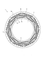
- FIG. 1 is a diagram illustrating a three-phase AC motor including a stator according to the first embodiment.
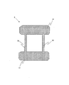
- FIG. 2 is a diagram illustrating an example of an interphase insulating material used in the stator according to the first embodiment.
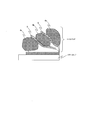
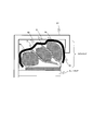
- FIG. 3 is a cross-sectional view of the coil end.
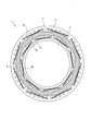
- FIG. 4 is a diagram illustrating a three-phase AC motor including a stator according to the second embodiment.
- FIG. 5 is a diagram illustrating an example of an interphase insulating material used in the stator according to the second embodiment.
- FIG. 6 is a cross-sectional view of a coil end in the stator of the second embodiment.
- FIG. 7 is a diagram illustrating a three-phase AC motor including a stator having a configuration in which all V-phase coils are collectively covered with one annular interphase insulating material.
- FIG. 8 is a cross-sectional view of a coil end of a three-phase AC motor including a stator according to the third embodiment.
- FIG. 9 is a cross-sectional view of a coil end of a three-phase AC motor including a stator according to the fourth embodiment.
- FIG. 1 is a diagram illustrating a three-phase AC motor 1 including a stator 2 according to the first embodiment.
- the three-phase AC motor 1 includes an annular stator 2 and a rotor 3 that is rotatably disposed on the inner peripheral side of the stator 2.
- the stator 2 is provided with a plurality of teeth 21 formed so as to protrude radially inward, and slots 22 are formed between the teeth.
- a U-phase coil 4a, a V-phase coil 4b, and a W-phase coil 4c are distributed around the teeth 21 in order from the outside (outer peripheral side) of the teeth 21. It is necessary to insulate between the phase coils, particularly at the coil end where each coil protrudes from the end of the tooth. Therefore, as shown in FIG. 1, the interphase insulation at the coil end is performed by interposing the interphase insulating material 5 between the coils.
- FIG. 2 is a diagram illustrating an example of the interphase insulating material 5.
- the interphase insulating material 5 shown in FIG. 2 includes an insulating portion 51 disposed at the coil ends at both ends of the stator 2 and a connecting portion 52 that connects the insulating portions 51 at both ends.
- the insulating part 51 and the connecting part 52 can be formed of the same material.
- FIG. 3 is a cross-sectional view of the coil end. As shown in FIG. 3, the interphase insulating material 5 is interposed between the U-phase coil 4 a and the V-phase coil 4 b and between the V-phase coil 4 b and the W-phase coil 4 c. Insulate.
- the interphase insulating material 5 is composed of a knitted fabric made of fibers having at least an insulating performance.
- the knitted fabric is manufactured by knitting while forming a loop with yarn.
- the fibers used in the knitted fabric include aramid fibers, polyphenylene sulfide (PPS) fibers, polybenzobisoxazole (PBO) fibers, polybenzobisthiazole (PBT) fibers, wholly aromatic polyester fibers, and dynea (PE) fibers. Or consist of one kind.
- Knitting methods include weft knitting (horizontal knitting and weft knitting) and warp knitting (warp knitting and warp knitting).
- Weft knitting includes flat knitting (generally called Tenshi knitting), rib knitting (also called milling knitting, rubber knitting), double-sided knitting (also called interlock knitting, smooth knitting), pearl knitting (links knitting, garter knitting) Also called circular knitting).
- the warp knitting includes tricot knitting, Atlas knitting, diamond knitting, and Milanese knitting.
- the knitting method of the knitted material constituting the interphase insulating material 5 is not limited to the above-described knitting method.
- the interphase insulating material 5 interposed between the coils is solidified integrally with the coil by a resin material.
- the resin material is made of, for example, a thermosetting resin including a phenol resin, an epoxy resin, and an unsaturated polyester resin.
- the resin is easily infiltrated and effectively solidified as compared with the case where the interphase insulating material constituted by the woven fabric is used. Can be made.
- the woven fabric is produced by crossing warp and weft.
- the target stator 2 is a stator of a motor formed by distributed winding of multiphase coils.
- a U-phase coil, a V-phase coil, and a W-phase coil are installed in order from the outer peripheral side on a stator core that constitutes a three-phase AC motor.
- each coil at the coil end and the interphase insulating material are integrally solidified with a resin material.
- the stator in the first embodiment is a stator 2 of a motor formed by distributedly winding multiphase coils, and among the coils forming each phase, at least the interphase insulating material 5 between the coils at the coil end.
- the interphase insulating material 5 is composed of a knitted fabric made of fibers having an insulating performance. Since the knitted fabric is highly stretchable, even if the coil is deformed during the molding of the stator, the interphase insulating material 5 expands and contracts in accordance with the deformation of the coil. Can be secured. Moreover, since the interphase insulating material 5 expands and contracts, the interphase insulating material 5 is not cut by deformation of the coil.
- the knitted fabric is manufactured by knitting while creating a loop with yarn, but since the yarn is high, the coils can be reliably insulated. Furthermore, when the coils at the coil end and the interphase insulating material 5 are solidified integrally with a resin material, the knitted fabric has a larger opening ratio than the woven fabric, so compared with the case where the interphase insulating material configured by the woven fabric is used. The resin can penetrate easily and can be solidified effectively.
- the fibers constituting the knitted fabric are any one of aramid fibers, polyphenylene sulfide fibers, polybenzobisoxazole fibers, polybenzobisthiazole fibers, wholly aromatic polyester fibers, and Dyneema fibers.
- Para- or meta-aramid fibers have high compression performance and deformation performance.
- Polybenzobisoxazole fibers, polybenzobisthiazole fibers, wholly aromatic polyester fibers, and Dyneema fibers also have high strength. It is suitable for the interphase insulating material 5 in the form. These fibers have high heat resistance.
- the required heat resistance can be obtained by integrally solidifying each coil and the interphase insulating material 5 at the coil end using a thermosetting resin including a phenol resin, an epoxy resin, and an unsaturated polyester resin.
- FIG. 4 is a diagram illustrating a three-phase AC motor 1 including the stator 2 according to the second embodiment.
- the same components as those shown in FIG. 1 are denoted by the same reference numerals, and detailed description thereof is omitted.
- the stator in the second embodiment differs from the stator in the first embodiment in the shape and arrangement method of the interphase insulating material 5.
- FIG. 5 is a diagram illustrating an example of the interphase insulating material 5 used in the stator according to the second embodiment.
- the interphase insulating material 5 shown in FIG. 5 includes a set of insulating portions 53 that respectively cover a set of coil ends at both ends of the stator, and a connecting portion 54 that connects the set of insulating portions 53.
- Insulating portion 53 is disposed so as to cover a V-phase coil located in the middle among U-phase coil, V-phase coil, and W-phase coil. More specifically, one V-phase coil is covered by the insulating portion 53 of one interphase insulating material 5. Not only the V-phase coil located in the middle, but also the U-phase coil and / or the W-phase coil may be covered.
- FIG. 6 is a cross-sectional view of a coil end in the stator of the second embodiment.
- the interphase insulating material 5 is disposed so as to cover the coil end of the V-phase coil 4 b, and thereby, between the U-phase coil 4 a and the V-phase coil 4 b and the V-phase coil.
- the coil 4b and the W-phase coil 4W are insulated from each other.
- FIG. 7 is a diagram showing a three-phase AC motor 1 including a stator 2 having a configuration in which all V-phase coils 4 b are collectively covered with a single annular interphase insulating material 5.
- the interphase insulating material 5 is disposed so as to cover at least the coil located in the middle among the coils. Thereby, between the coil located in the middle and the coil located on both sides thereof can be insulated by one interphase insulating material 5. Further, since the interphase insulating material 5 is disposed so as to cover the coil, the interphase insulating material 5 can be easily disposed.
- the interphase insulating material 5 includes a pair of insulating portions 53 that respectively cover a pair of coil ends at both ends of the stator 2, and a connecting portion 54 that connects the pair of insulating portions 53. Thereby, the insulation between the coils located at both ends of the stator 2 can be insulated by one interphase insulating material 5. In addition, since the coils positioned at both ends of the stator 2 are simply disposed so as to be covered with the insulating portion 53, the interphase insulating material 5 can be easily disposed.
- FIG. 8 is a cross-sectional view of the coil end of the three-phase AC motor 1 including the stator 2 according to the third embodiment.
- the stator in the third embodiment is based on the stator in the first embodiment, and the same components as those shown in FIG.
- the interphase insulating material 5 is inserted between the coils at the coil end, and the coils 4a, 4b, and 4c at the coil end and the stator housing that houses the stator.
- Insulating material 10 is provided to insulate between 11 and 11. More specifically, the insulating material 10 is provided so as to cover the entire coil at the coil end.
- the insulating material 10 is made of the same material as the interphase insulating material 5, that is, a knitted fabric made of fibers having at least an insulating performance.
- the insulating material 10 provided so as to cover the entire coil at the coil end is solidified integrally with the coil by the resin material.
- the resin material is made of a thermosetting resin including a phenol resin, an epoxy resin, and an unsaturated polyester resin.
- the coil 4a which is composed of a knitted fabric made of fibers having at least insulation performance, is formed with respect to the configuration of the stator in the first embodiment, and forms each phase.
- An insulating material 10 is further provided for insulating between 4b and 4c and the stator housing 11 that houses the stator.
- the insulation is ensured by maintaining the distance between the coil and the stator housing at the coil end by a predetermined distance (insulation distance) or more. Since it is not necessary to maintain the insulation distance between the coil and the stator housing at the end, the size of the three-phase AC motor 1 including the stator housing 11 can be reduced.
- FIG. 9 is a cross-sectional view of the coil end of the three-phase AC motor 1 including the stator 2 according to the fourth embodiment.
- the stator in the fourth embodiment is based on the stator in the second embodiment, and the same reference numerals are given to the same components as those shown in FIG.
- the correlation insulating material 5 is provided so as to cover the coil end of the V-phase coil 4b, and the coils 4a, 4b, 4c at the coil end and the stator are accommodated.
- An insulating material 10 for insulating the stator housing 11 is provided. More specifically, the insulating material 10 is provided so as to cover the entire coil at the coil end.
- the insulating material 10 is made of the same material as the interphase insulating material 5, that is, a knitted fabric made of fibers having at least an insulating performance.
- the insulating material 10 provided so as to cover the entire coil at the coil end is solidified integrally with the coil by the resin material.
- the resin material is made of a thermosetting resin including a phenol resin, an epoxy resin, and an unsaturated polyester resin.
- the interphase insulating material 5 covering the V-phase coil 4b located in the middle may be used individually for each V-phase coil 4b, or all the V-phase coils 4b are combined by one inter-phase insulating material 5. It is good also as a structure covered.
- the interphase insulating material 5 is disposed so as to cover the V-phase coil 4b located in the middle of the U-phase coil 4a, the V-phase coil 4b, and the W-phase coil 4c. / Or W phase coil 4c may be covered.
- the coil 4a which is composed of a knitted fabric made of fibers having at least an insulating performance with respect to the configuration of the stator in the second embodiment, forms each phase.
- An insulating material 10 is further provided for insulating between 4b and 4c and the stator housing 11 that houses the stator.
- the present invention is not limited to the embodiment described above.
- the shape of the interphase insulating material 5 is not limited to that shown in FIGS.
Landscapes
- Engineering & Computer Science (AREA)
- Power Engineering (AREA)
- Insulation, Fastening Of Motor, Generator Windings (AREA)
Abstract
多相コイルを分布巻きしてなるモータのステータであって、各相を形成するコイル間のうち、少なくともコイルエンドにおけるコイル間には相間絶縁材が介装されており、コイルエンドにおける各コイルと相間絶縁材とが樹脂材にて一体固化されてなるステータにおいて、相間絶縁材は、少なくとも絶縁性能を備えた繊維からなる編物から構成されている。
Description
本発明は、多相コイルを分布巻きしてなるモータのステータ、及び、ステータのコイル相間の絶縁方法に関する。
従来、多相コイルを分布巻きしてなるモータのステータであって、各相を形成するコイル間のうち、少なくともコイルエンドにおけるコイル間には相間絶縁材が介装されており、コイルエンドにおける各コイルと相間絶縁材とが樹脂材にて一体固化されてなるステータがある。このステータにおいて、相間絶縁材を、少なくとも絶縁性能を備えた繊維からなる織物から構成したものが知られている(JP2006-217679A)。
しかしながら、織物は網目の密度が緻密で強度が強いため、大きい変形には追随できず、ステータの成形時に、相間絶縁材がずれて絶縁性が悪化する可能性がある。
本発明は、大きい変形にも追随できる相間絶縁材を備えたステータを提供することを目的とする。
一実施形態におけるステータは、多相コイルを分布巻きしてなるモータのステータであって、各相を形成するコイル間のうち、少なくともコイルエンドにおけるコイル間には相間絶縁材が介装されており、コイルエンドにおける各コイルと相間絶縁材とが樹脂材にて一体固化されてなるステータである。このステータにおいて、相間絶縁材は、絶縁性能を備えた繊維からなる編物から構成されている。
本発明の実施形態、本発明の利点については、添付された図面とともに以下に詳細に説明される。
-第1の実施形態-
図1は、第1の実施形態におけるステータ2を備えた三相交流モータ1を示す図である。三相交流モータ1は、環状のステータ2と、ステータ2の内周側に回転可能に配設されるロータ3とを備える。
図1は、第1の実施形態におけるステータ2を備えた三相交流モータ1を示す図である。三相交流モータ1は、環状のステータ2と、ステータ2の内周側に回転可能に配設されるロータ3とを備える。
ステータ2は、径方向内側に突出するように形成された複数のティース21が設けられており、ティース間にはスロット22が形成されている。
図1に示すように、ステータ2では、ティース21の外側(外周側)から順に、U相コイル4a、V相コイル4b、W相コイル4cがそれぞれティース21に分布巻きされている。各相コイル間、特に、各コイルがティースの端部から突出したコイルエンドにおいては、相間の絶縁を行う必要がある。従って、図1に示すように、各コイル間に相間絶縁材5を介装させることにより、コイルエンドにおける相間絶縁を行う。
図2は、相間絶縁材5の一例を示す図である。図2に示す相間絶縁材5は、ステータ2の両端のコイルエンドに配設される絶縁部51と、両端の絶縁部51を繋ぐ繋ぎ部52とにより構成される。絶縁部51と繋ぎ部52とは同一の材料にて成形可能である。
図3は、コイルエンドの断面図である。図3に示すように、相間絶縁材5は、U相コイル4aとV相コイル4bとの間、および、V相コイル4bとW相コイル4cとの間のコイル間に介装され、コイル間を絶縁する。
相間絶縁材5は、少なくとも絶縁性能を備えた繊維からなる編物により構成されている。ここで、編物とは、糸でループを作りながら編み合わせて製造されたものである。編物に用いられる繊維は、例えば、アラミド繊維、ポリフェニレンサルファイド(PPS)繊維、ポリベンゾビスオキサゾール(PBO)繊維、ポリベンゾビスチアゾール(PBT)繊維、全芳香族ポリエステル繊維、ダイニーマ(PE)繊維のいずれか1種からなる。
編物の編み方としては、緯編み(横編み・ヨコ編み)や経編み(縦編み・タテ編み)がある。緯編みには、平編み(一般的に天竺編みと呼ぶ)、リブ編み(フライス編み、ゴム編みとも呼ぶ)、両面編み(インターロック編み、スムース編みとも呼ぶ)、パール編み(リンクス編み、ガーター編みとも呼ぶ)、丸編みなどがある。また、経編みには、トリコット編み、アトラス編み、ダイヤモンド編み、ミラニーズ編みなどがある。ただし、相間絶縁材5を構成する編物の編み方が上述した編み方に限定されることはない。
コイル間に介装された相間絶縁材5は、樹脂材によってコイルと一体固化される。樹脂材は、例えば、フェノール樹脂、エポキシ樹脂、不飽和ポリエステル樹脂を含む熱硬化性樹脂からなる。本実施形態では、織物と比べて開口率の大きい編物により構成される相間絶縁材5を用いるので、織物により構成される相間絶縁材を用いる場合に比べて、樹脂が染み込みやすく、効果的に固化させることができる。なお、織物とは、たて糸とよこ糸とを交錯させて製造されたものである。
本実施形態におけるコイル相間の絶縁方法について説明する。対象となるステータ2は、多相コイルを分布巻きしてなるモータのステータである。ここでは、3相交流モータを構成するステータコアに、外周側から順にU相コイル、V相コイル、W相コイルを設置する例を挙げて説明する。
最初に、複数のティースに跨るU相コイルを設置する。次に、図2に示すような相間絶縁材をステータコアに設置する。次にV相コイルの設置、図2に示すような相間絶縁材の設置、W相コイルの設置を順に行う。これにより、相間絶縁材は、U相コイルとV相コイル間、V相コイルとW相コイル間に介装された状態となる。以上の工程が第1工程となる。
次に、第2工程として、コイルエンドにおける各コイルと相間絶縁材とを樹脂材にて一体固化させる。
以上、第1の実施形態におけるステータは、多相コイルを分布巻きしてなるモータのステータ2であって、各相を形成するコイル間のうち、少なくともコイルエンドにおけるコイル間には相間絶縁材5が介装されており、コイルエンドにおける各コイルと相間絶縁材5とが樹脂材にて一体固化されてなるステータである。このステータ2において、相間絶縁材5は、絶縁性能を備えた繊維からなる編物から構成されている。編物は伸縮性が高いので、ステータ成形時にコイルが変形しても、コイルの変形に応じて相間絶縁材5が伸縮するので、相間絶縁材5の位置がずれることはなく、コイル間の絶縁を確保することができる。また、相間絶縁材5が伸縮するので、コイルの変形によって相間絶縁材5が切れることもない。
また、編物は、糸でループを作りながら編み合わせて製造されたものであるが、糸のかさが高いのでコイル間を確実に絶縁することができる。さらに、コイルエンドにおける各コイルと相間絶縁材5とを樹脂材にて一体固化させる際に、編物は、織物と比べて開口率が大きいので、織物により構成される相間絶縁材を用いる場合に比べて樹脂が染み込みやすく、効果的に固化させることができる。
編物を構成する繊維は、アラミド繊維、ポリフェニレンサルファイド繊維、ポリベンゾビスオキサゾール繊維、ポリベンゾビスチアゾール繊維、全芳香族ポリエステル繊維、ダイニーマ繊維のいずれか1種からなる。パラ系またはメタ系のアラミド繊維は圧縮性能や変形性能が高く、また、ポリベンゾビスオキサゾール繊維、ポリベンゾビスチアゾール繊維、全芳香族ポリエステル繊維、ダイニーマ繊維も高い強度を有しており、本実施形態における相間絶縁材5には好適である。これらの繊維は、耐熱性も高い。
フェノール樹脂、エポキシ樹脂、不飽和ポリエステル樹脂を含む熱硬化性樹脂を用いてコイルエンドにおける各コイルと相間絶縁材5とを一体固化することにより、要求される耐熱性能を得ることができる。
-第2の実施形態-
図4は、第2の実施形態におけるステータ2を備えた三相交流モータ1を示す図である。図1に示す構成と同一の構成部分には同一の符号を付して詳しい説明は省略する。第2の実施形態におけるステータが第1の実施形態におけるステータと異なるのは、相間絶縁材5の形状および配設方法である。
図4は、第2の実施形態におけるステータ2を備えた三相交流モータ1を示す図である。図1に示す構成と同一の構成部分には同一の符号を付して詳しい説明は省略する。第2の実施形態におけるステータが第1の実施形態におけるステータと異なるのは、相間絶縁材5の形状および配設方法である。
図5は、第2の実施形態におけるステータに用いられる相間絶縁材5の一例を示す図である。図5に示す相間絶縁材5は、ステータの両端の一組のコイルエンドをそれぞれ覆う一組の絶縁部53と、一組の絶縁部53を繋ぐ繋ぎ部54とを備える。絶縁部53は、U相コイル、V相コイル、W相コイルのうち、中間に位置するV相コイルを覆うように配設される。より具体的には、1つの相間絶縁材5の絶縁部53によって、1つのV相コイルを覆う。なお、中間に位置するV相コイルだけでなく、U相コイルおよび/またはW相コイルも覆うようにしてもよい。
図6は、第2の実施形態のステータにおけるコイルエンドの断面図である。図5に示すように、相間絶縁材5は、V相コイル4bのコイルエンドを覆うように配設されており、これにより、U相コイル4aとV相コイル4bとの間、および、V相コイル4bとW相コイル4Wとの間が絶縁される。
図4に示す例では、中間に位置するV相コイル4bをそれぞれ個別の相間絶縁材5によって覆う構成としたが、1つの相間絶縁材5によって全てのV相コイル4bをまとめて覆う構成としてもよい。図7は、環状の1つの相間絶縁材5によって全てのV相コイル4bをまとめて覆う構成のステータ2を備えた三相交流モータ1を示す図である。
以上、第2の実施形態におけるステータによれば、相間絶縁材5は、各コイルのうち、少なくとも中間に位置するコイルを覆うように配設されている。これにより、中間に位置するコイルとその両隣に位置するコイルとの間を1つの相間絶縁材5によって絶縁することができる。また、コイルを覆うように相間絶縁材5を配設するので、相間絶縁材5を容易に配設することができる。
相間絶縁材5は、ステータ2の両端の一組のコイルエンドをそれぞれ覆う一組の絶縁部53と、一組の絶縁部53を繋ぐ繋ぎ部54とを備える。これにより、ステータ2の両端に位置するコイル間の絶縁を1つの相間絶縁材5によって絶縁することができる。また、ステータ2の両端に位置するコイルそれぞれを絶縁部53で覆うように配置するだけなので、相間絶縁材5を容易に配設することができる。
-第3の実施形態-
図8は、第3の実施形態におけるステータ2を備えた三相交流モータ1のコイルエンドの断面図である。第3の実施形態におけるステータは、第1の実施形態におけるステータがベースとなっており、図3に示す構成と同一の構成部分には同一の符号を付している。
図8は、第3の実施形態におけるステータ2を備えた三相交流モータ1のコイルエンドの断面図である。第3の実施形態におけるステータは、第1の実施形態におけるステータがベースとなっており、図3に示す構成と同一の構成部分には同一の符号を付している。
図8に示すように、第3の実施形態におけるステータでは、コイルエンドにおける各コイル間に相間絶縁材5が介挿されるとともに、コイルエンドにおけるコイル4a、4b、4cと、ステータを収容するステータハウジング11との間を絶縁するための絶縁材10が設けられている。より具体的には、コイルエンドにおけるコイル全体を覆うように、絶縁材10が設けられている。
この絶縁材10は、相間絶縁材5と同じ素材、すなわち、少なくとも絶縁性能を備えた繊維からなる編物により構成されている。
コイルエンドにおけるコイル全体を覆うように設けられた絶縁材10は、樹脂材によってコイルと一体固化される。樹脂材は、フェノール樹脂、エポキシ樹脂、不飽和ポリエステル樹脂を含む熱硬化性樹脂からなる。
以上、第3の実施形態におけるステータによれば、第1の実施形態におけるステータの構成に対して、少なくとも絶縁性能を備えた繊維からなる編物から構成されており、各相を形成するコイル4a、4b、4cと、ステータを収容するステータハウジング11との間を絶縁するための絶縁材10をさらに設けた。この絶縁材10を設けない従来のステータでは、コイルエンドにおけるコイルとステータハウジングとの間を所定の距離(絶縁距離)以上保つことによって絶縁を確保していたが、本実施形態におけるステータでは、コイルエンドにおけるコイルとステータハウジングとの間の絶縁距離を保つ必要がないので、ステータハウジング11を含む三相交流モータ1の大きさを小さくすることができる。
-第4の実施形態-
図9は、第4の実施形態におけるステータ2を備えた三相交流モータ1のコイルエンドの断面図である。第4の実施形態におけるステータは、第2の実施形態におけるステータがベースとなっており、図6に示す構成と同一の構成部分には同一の符号を付している。
図9は、第4の実施形態におけるステータ2を備えた三相交流モータ1のコイルエンドの断面図である。第4の実施形態におけるステータは、第2の実施形態におけるステータがベースとなっており、図6に示す構成と同一の構成部分には同一の符号を付している。
図9に示すように、第4の実施形態におけるステータでは、V相コイル4bのコイルエンドを覆うように相関絶縁材5が設けられるとともに、コイルエンドにおけるコイル4a、4b、4cと、ステータを収容するステータハウジング11との間を絶縁するための絶縁材10が設けられている。より具体的には、コイルエンドにおけるコイル全体を覆うように、絶縁材10が設けられている。
この絶縁材10は、相間絶縁材5と同じ素材、すなわち、少なくとも絶縁性能を備えた繊維からなる編物により構成されている。
コイルエンドにおけるコイル全体を覆うように設けられた絶縁材10は、樹脂材によってコイルと一体固化される。樹脂材は、フェノール樹脂、エポキシ樹脂、不飽和ポリエステル樹脂を含む熱硬化性樹脂からなる。
なお、中間に位置するV相コイル4bを覆う相間絶縁材5は、V相コイル4bごとにそれぞれ個別のものを用いてもよいし、1つの相間絶縁材5によって全てのV相コイル4bをまとめて覆う構成としてもよい。また、図9では、U相コイル4a、V相コイル4b、W相コイル4cのうち、中間に位置するV相コイル4bを覆うように相間絶縁材5を配設したが、U相コイル4aおよび/またはW相コイル4cも覆うようにしてもよい。
以上、第4の実施形態におけるステータによれば、第2の実施形態におけるステータの構成に対して、少なくとも絶縁性能を備えた繊維からなる編物から構成されており、各相を形成するコイル4a、4b、4cと、ステータを収容するステータハウジング11との間を絶縁するための絶縁材10をさらに設けた。これにより、第3の実施形態におけるステータと同様に、ステータハウジング11を含む三相交流モータ1の大きさを小さくすることができる。
本発明は、上述した実施形態に限定されることはない。例えば、相間絶縁材5の形状は図2や図5に示すものに限定されることはない。
本願は、2012年7月3日に日本国特許庁に出願された特願2012-149707、および、2013年4月19日に日本国特許庁に出願された特願2013-088588に基づく優先権を主張し、この出願の全ての内容は参照により本明細書に組み込まれる。
Claims (11)
- 多相コイルを分布巻きしてなるモータのステータであって、各相を形成するコイル間のうち、少なくともコイルエンドにおけるコイル間には相間絶縁材が介装されており、コイルエンドにおける各コイルと相間絶縁材とが樹脂材にて一体固化されてなるステータにおいて、
前記相間絶縁材は、少なくとも絶縁性能を備えた繊維からなる編物から構成されているステータ。 - 請求項1に記載のステータにおいて、
前記相間絶縁材は、各コイルのうち、少なくとも中間に位置するコイルを覆うように配設されているステータ。 - 請求項2に記載のステータにおいて、
前記相間絶縁材は、ステータの両端の一組のコイルエンドをそれぞれ覆う一組の絶縁部と、前記一組の絶縁部を繋ぐ繋ぎ部とを備えるステータ。 - 請求項1から請求項3のいずれか一項に記載のステータにおいて、
少なくとも絶縁性能を備えた繊維からなる編物から構成されており、各相を形成するコイルと、ステータを収容するステータハウジングとの間を絶縁するための絶縁材をさらに設けたステータ。 - 請求項1から請求項4のいずれか一項に記載のステータにおいて、
前記繊維は、アラミド繊維、ポリフェニレンサルファイド繊維、ポリベンゾビスオキサゾール繊維、ポリベンゾビスチアゾール繊維、全芳香族ポリエステル繊維、ダイニーマ繊維のいずれか1種からなるステータ。 - 請求項1から請求項5のいずれか一項に記載のステータにおいて、
前記樹脂材は、フェノール樹脂、エポキシ樹脂、不飽和ポリエステル樹脂を含む熱硬化性樹脂からなるステータ。 - 多相コイルを分布巻きしてなるモータのステータにおけるコイル相間の絶縁方法であって、
各相を構成するそれぞれのコイルをステータコアに装着するとともに、編物からなる相間絶縁材を各コイル間に装着する第一工程と、コイルエンドにおける各コイルと相間絶縁材とを樹脂材にて一体固化させる第二工程と、を備えるコイル相間の絶縁方法。 - 請求項7に記載のコイル相間の絶縁方法において、
前記相間絶縁材は、ステータの両端の一組のコイルエンドをそれぞれ覆う一組の絶縁部と、前記一組の絶縁部を繋ぐ繋ぎ部とを備えるコイル相間の絶縁方法。 - 請求項7または請求項8のいずれか一項に記載のコイル相間の絶縁方法において、
各相を形成するコイルと、ステータを収容するステータハウジングとの間を絶縁するために、編物からなる絶縁材を配設する第三工程をさらに備えるコイル相間の絶縁方法。 - 請求項9に記載のコイル相間の絶縁方法において、
前記第三工程に次いで編物からなる絶縁材を樹脂材にて一体固化させる第四工程をさらに備えるコイル相間の絶縁方法。 - 請求項7から請求項10のいずれか一項に記載のコイル相間の絶縁方法において、
前記繊維は、アラミド繊維、ポリフェニレンサルファイド繊維、ポリベンゾビスオキサゾール繊維、ポリベンゾビスチアゾール繊維、全芳香族ポリエステル繊維、ダイニーマ繊維のいずれか1種からなり、前記樹脂材は、フェノール樹脂、エポキシ樹脂、不飽和ポリエステル樹脂を含む熱硬化性樹脂からなるコイル相間の絶縁方法。
Applications Claiming Priority (4)
| Application Number | Priority Date | Filing Date | Title |
|---|---|---|---|
| JP2012-149707 | 2012-07-03 | ||
| JP2012149707 | 2012-07-03 | ||
| JP2013-088588 | 2013-04-19 | ||
| JP2013088588A JP2014030337A (ja) | 2012-07-03 | 2013-04-19 | ステータ及びコイル相間の絶縁方法 |
Publications (1)
| Publication Number | Publication Date |
|---|---|
| WO2014007115A1 true WO2014007115A1 (ja) | 2014-01-09 |
Family
ID=49881872
Family Applications (1)
| Application Number | Title | Priority Date | Filing Date |
|---|---|---|---|
| PCT/JP2013/067449 Ceased WO2014007115A1 (ja) | 2012-07-03 | 2013-06-26 | ステータ及びコイル相間の絶縁方法 |
Country Status (2)
| Country | Link |
|---|---|
| JP (1) | JP2014030337A (ja) |
| WO (1) | WO2014007115A1 (ja) |
Families Citing this family (1)
| Publication number | Priority date | Publication date | Assignee | Title |
|---|---|---|---|---|
| JP7509058B2 (ja) | 2021-03-03 | 2024-07-02 | 株式会社明電舎 | 相間絶縁紙及び回転電機 |
Citations (6)
| Publication number | Priority date | Publication date | Assignee | Title |
|---|---|---|---|---|
| JPS58193837U (ja) * | 1982-06-17 | 1983-12-23 | 株式会社東芝 | 相間絶縁紙 |
| JPS59169564U (ja) * | 1983-04-28 | 1984-11-13 | 株式会社東芝 | モ−タコイルエンドの結束構造 |
| JPH09322456A (ja) * | 1996-05-30 | 1997-12-12 | Shinko Kagaku Kogyo Kk | モーターステーター及びその製造方法 |
| JP2004364382A (ja) * | 2003-06-03 | 2004-12-24 | Aisin Aw Co Ltd | 三相モータ用相間絶縁紙 |
| JP2006217679A (ja) * | 2005-02-01 | 2006-08-17 | Toyota Motor Corp | ステータおよびコイル相間の絶縁方法 |
| JP2010528571A (ja) * | 2007-05-18 | 2010-08-19 | イー・アイ・デュポン・ドウ・ヌムール・アンド・カンパニー | 積層電気絶縁部分を含む電気装置構成要素を修復する方法および前記部分を含む電気装置構成要素 |
-
2013
- 2013-04-19 JP JP2013088588A patent/JP2014030337A/ja active Pending
- 2013-06-26 WO PCT/JP2013/067449 patent/WO2014007115A1/ja not_active Ceased
Patent Citations (6)
| Publication number | Priority date | Publication date | Assignee | Title |
|---|---|---|---|---|
| JPS58193837U (ja) * | 1982-06-17 | 1983-12-23 | 株式会社東芝 | 相間絶縁紙 |
| JPS59169564U (ja) * | 1983-04-28 | 1984-11-13 | 株式会社東芝 | モ−タコイルエンドの結束構造 |
| JPH09322456A (ja) * | 1996-05-30 | 1997-12-12 | Shinko Kagaku Kogyo Kk | モーターステーター及びその製造方法 |
| JP2004364382A (ja) * | 2003-06-03 | 2004-12-24 | Aisin Aw Co Ltd | 三相モータ用相間絶縁紙 |
| JP2006217679A (ja) * | 2005-02-01 | 2006-08-17 | Toyota Motor Corp | ステータおよびコイル相間の絶縁方法 |
| JP2010528571A (ja) * | 2007-05-18 | 2010-08-19 | イー・アイ・デュポン・ドウ・ヌムール・アンド・カンパニー | 積層電気絶縁部分を含む電気装置構成要素を修復する方法および前記部分を含む電気装置構成要素 |
Also Published As
| Publication number | Publication date |
|---|---|
| JP2014030337A (ja) | 2014-02-13 |
Similar Documents
| Publication | Publication Date | Title |
|---|---|---|
| JP5918353B2 (ja) | 回転電機のステータ構造 | |
| US8610328B2 (en) | Rotary electric machine | |
| US10305339B2 (en) | Rotating electrical machine and method of manufacturing the same | |
| JP5789570B2 (ja) | ステータ | |
| EP3151389A2 (en) | Rotary electric machine | |
| KR101606262B1 (ko) | 보빈 및 회전 전기 기기 | |
| JP6046987B2 (ja) | ステータ、ブラシレスモータ、ステータの製造方法 | |
| US11075559B2 (en) | Stator of rotating electric machine | |
| US20190273409A1 (en) | Slotless electric motor and coil unit thereof | |
| JP5502115B2 (ja) | ステータ、ブラシレスモータ、ステータの製造方法 | |
| WO2014136497A1 (ja) | バスバーユニット | |
| JP2012110212A (ja) | ステータ、ブラシレスモータ、ステータの製造方法 | |
| US9385568B2 (en) | Stator and electric motor having the same | |
| JP2010246343A5 (ja) | ||
| JP2016073083A (ja) | 回転電機ステータ | |
| US10608493B2 (en) | Stator for rotary electric machine having distributed winding structure | |
| KR101815794B1 (ko) | 전기 기계를 위한 절연 구성 및 조립 방법 | |
| JP6053647B2 (ja) | 回転電機の固定子、回転電機及び回転電機の製造方法 | |
| JP6200854B2 (ja) | 回転電機のステータ | |
| JP2014030337A (ja) | ステータ及びコイル相間の絶縁方法 | |
| JP2018050384A (ja) | 回転電機ステータ | |
| US20110266912A1 (en) | Rotating electric machine with a stator winding comprising a plurality of coils and method for manufacturing same | |
| US7868495B2 (en) | Electric motor core member | |
| WO2018168108A1 (ja) | 回転電機 | |
| JP2014192974A (ja) | ステータの構造及び組付方法 |
Legal Events
| Date | Code | Title | Description |
|---|---|---|---|
| 121 | Ep: the epo has been informed by wipo that ep was designated in this application |
Ref document number: 13813370 Country of ref document: EP Kind code of ref document: A1 |
|
| NENP | Non-entry into the national phase |
Ref country code: DE |
|
| 122 | Ep: pct application non-entry in european phase |
Ref document number: 13813370 Country of ref document: EP Kind code of ref document: A1 |