WO2014006705A1 - エンコーダ及びサーボモータ - Google Patents
エンコーダ及びサーボモータ Download PDFInfo
- Publication number
- WO2014006705A1 WO2014006705A1 PCT/JP2012/067106 JP2012067106W WO2014006705A1 WO 2014006705 A1 WO2014006705 A1 WO 2014006705A1 JP 2012067106 W JP2012067106 W JP 2012067106W WO 2014006705 A1 WO2014006705 A1 WO 2014006705A1
- Authority
- WO
- WIPO (PCT)
- Prior art keywords
- light source
- light
- light receiving
- array
- slit
- Prior art date
- Legal status (The legal status is an assumption and is not a legal conclusion. Google has not performed a legal analysis and makes no representation as to the accuracy of the status listed.)
- Ceased
Links
Images





Classifications
-
- G—PHYSICS
- G01—MEASURING; TESTING
- G01D—MEASURING NOT SPECIALLY ADAPTED FOR A SPECIFIC VARIABLE; ARRANGEMENTS FOR MEASURING TWO OR MORE VARIABLES NOT COVERED IN A SINGLE OTHER SUBCLASS; TARIFF METERING APPARATUS; MEASURING OR TESTING NOT OTHERWISE PROVIDED FOR
- G01D5/00—Mechanical means for transferring the output of a sensing member; Means for converting the output of a sensing member to another variable where the form or nature of the sensing member does not constrain the means for converting; Transducers not specially adapted for a specific variable
- G01D5/26—Mechanical means for transferring the output of a sensing member; Means for converting the output of a sensing member to another variable where the form or nature of the sensing member does not constrain the means for converting; Transducers not specially adapted for a specific variable characterised by optical transfer means, i.e. using infrared, visible, or ultraviolet light
- G01D5/32—Mechanical means for transferring the output of a sensing member; Means for converting the output of a sensing member to another variable where the form or nature of the sensing member does not constrain the means for converting; Transducers not specially adapted for a specific variable characterised by optical transfer means, i.e. using infrared, visible, or ultraviolet light with attenuation or whole or partial obturation of beams of light
- G01D5/34—Mechanical means for transferring the output of a sensing member; Means for converting the output of a sensing member to another variable where the form or nature of the sensing member does not constrain the means for converting; Transducers not specially adapted for a specific variable characterised by optical transfer means, i.e. using infrared, visible, or ultraviolet light with attenuation or whole or partial obturation of beams of light the beams of light being detected by photocells
- G01D5/347—Mechanical means for transferring the output of a sensing member; Means for converting the output of a sensing member to another variable where the form or nature of the sensing member does not constrain the means for converting; Transducers not specially adapted for a specific variable characterised by optical transfer means, i.e. using infrared, visible, or ultraviolet light with attenuation or whole or partial obturation of beams of light the beams of light being detected by photocells using displacement encoding scales
- G01D5/34776—Absolute encoders with analogue or digital scales
- G01D5/34792—Absolute encoders with analogue or digital scales with only digital scales or both digital and incremental scales
-
- G—PHYSICS
- G01—MEASURING; TESTING
- G01D—MEASURING NOT SPECIALLY ADAPTED FOR A SPECIFIC VARIABLE; ARRANGEMENTS FOR MEASURING TWO OR MORE VARIABLES NOT COVERED IN A SINGLE OTHER SUBCLASS; TARIFF METERING APPARATUS; MEASURING OR TESTING NOT OTHERWISE PROVIDED FOR
- G01D5/00—Mechanical means for transferring the output of a sensing member; Means for converting the output of a sensing member to another variable where the form or nature of the sensing member does not constrain the means for converting; Transducers not specially adapted for a specific variable
- G01D5/26—Mechanical means for transferring the output of a sensing member; Means for converting the output of a sensing member to another variable where the form or nature of the sensing member does not constrain the means for converting; Transducers not specially adapted for a specific variable characterised by optical transfer means, i.e. using infrared, visible, or ultraviolet light
- G01D5/32—Mechanical means for transferring the output of a sensing member; Means for converting the output of a sensing member to another variable where the form or nature of the sensing member does not constrain the means for converting; Transducers not specially adapted for a specific variable characterised by optical transfer means, i.e. using infrared, visible, or ultraviolet light with attenuation or whole or partial obturation of beams of light
- G01D5/34—Mechanical means for transferring the output of a sensing member; Means for converting the output of a sensing member to another variable where the form or nature of the sensing member does not constrain the means for converting; Transducers not specially adapted for a specific variable characterised by optical transfer means, i.e. using infrared, visible, or ultraviolet light with attenuation or whole or partial obturation of beams of light the beams of light being detected by photocells
- G01D5/347—Mechanical means for transferring the output of a sensing member; Means for converting the output of a sensing member to another variable where the form or nature of the sensing member does not constrain the means for converting; Transducers not specially adapted for a specific variable characterised by optical transfer means, i.e. using infrared, visible, or ultraviolet light with attenuation or whole or partial obturation of beams of light the beams of light being detected by photocells using displacement encoding scales
- G01D5/34707—Scales; Discs, e.g. fixation, fabrication, compensation
-
- G—PHYSICS
- G01—MEASURING; TESTING
- G01D—MEASURING NOT SPECIALLY ADAPTED FOR A SPECIFIC VARIABLE; ARRANGEMENTS FOR MEASURING TWO OR MORE VARIABLES NOT COVERED IN A SINGLE OTHER SUBCLASS; TARIFF METERING APPARATUS; MEASURING OR TESTING NOT OTHERWISE PROVIDED FOR
- G01D5/00—Mechanical means for transferring the output of a sensing member; Means for converting the output of a sensing member to another variable where the form or nature of the sensing member does not constrain the means for converting; Transducers not specially adapted for a specific variable
- G01D5/26—Mechanical means for transferring the output of a sensing member; Means for converting the output of a sensing member to another variable where the form or nature of the sensing member does not constrain the means for converting; Transducers not specially adapted for a specific variable characterised by optical transfer means, i.e. using infrared, visible, or ultraviolet light
- G01D5/32—Mechanical means for transferring the output of a sensing member; Means for converting the output of a sensing member to another variable where the form or nature of the sensing member does not constrain the means for converting; Transducers not specially adapted for a specific variable characterised by optical transfer means, i.e. using infrared, visible, or ultraviolet light with attenuation or whole or partial obturation of beams of light
- G01D5/34—Mechanical means for transferring the output of a sensing member; Means for converting the output of a sensing member to another variable where the form or nature of the sensing member does not constrain the means for converting; Transducers not specially adapted for a specific variable characterised by optical transfer means, i.e. using infrared, visible, or ultraviolet light with attenuation or whole or partial obturation of beams of light the beams of light being detected by photocells
- G01D5/347—Mechanical means for transferring the output of a sensing member; Means for converting the output of a sensing member to another variable where the form or nature of the sensing member does not constrain the means for converting; Transducers not specially adapted for a specific variable characterised by optical transfer means, i.e. using infrared, visible, or ultraviolet light with attenuation or whole or partial obturation of beams of light the beams of light being detected by photocells using displacement encoding scales
- G01D5/34707—Scales; Discs, e.g. fixation, fabrication, compensation
- G01D5/34715—Scale reading or illumination devices
-
- G—PHYSICS
- G01—MEASURING; TESTING
- G01D—MEASURING NOT SPECIALLY ADAPTED FOR A SPECIFIC VARIABLE; ARRANGEMENTS FOR MEASURING TWO OR MORE VARIABLES NOT COVERED IN A SINGLE OTHER SUBCLASS; TARIFF METERING APPARATUS; MEASURING OR TESTING NOT OTHERWISE PROVIDED FOR
- G01D5/00—Mechanical means for transferring the output of a sensing member; Means for converting the output of a sensing member to another variable where the form or nature of the sensing member does not constrain the means for converting; Transducers not specially adapted for a specific variable
- G01D5/26—Mechanical means for transferring the output of a sensing member; Means for converting the output of a sensing member to another variable where the form or nature of the sensing member does not constrain the means for converting; Transducers not specially adapted for a specific variable characterised by optical transfer means, i.e. using infrared, visible, or ultraviolet light
- G01D5/32—Mechanical means for transferring the output of a sensing member; Means for converting the output of a sensing member to another variable where the form or nature of the sensing member does not constrain the means for converting; Transducers not specially adapted for a specific variable characterised by optical transfer means, i.e. using infrared, visible, or ultraviolet light with attenuation or whole or partial obturation of beams of light
- G01D5/34—Mechanical means for transferring the output of a sensing member; Means for converting the output of a sensing member to another variable where the form or nature of the sensing member does not constrain the means for converting; Transducers not specially adapted for a specific variable characterised by optical transfer means, i.e. using infrared, visible, or ultraviolet light with attenuation or whole or partial obturation of beams of light the beams of light being detected by photocells
- G01D5/347—Mechanical means for transferring the output of a sensing member; Means for converting the output of a sensing member to another variable where the form or nature of the sensing member does not constrain the means for converting; Transducers not specially adapted for a specific variable characterised by optical transfer means, i.e. using infrared, visible, or ultraviolet light with attenuation or whole or partial obturation of beams of light the beams of light being detected by photocells using displacement encoding scales
- G01D5/3473—Circular or rotary encoders
-
- H—ELECTRICITY
- H02—GENERATION; CONVERSION OR DISTRIBUTION OF ELECTRIC POWER
- H02K—DYNAMO-ELECTRIC MACHINES
- H02K11/00—Structural association of dynamo-electric machines with electric components or with devices for shielding, monitoring or protection
- H02K11/20—Structural association of dynamo-electric machines with electric components or with devices for shielding, monitoring or protection for measuring, monitoring, testing, protecting or switching
- H02K11/21—Devices for sensing speed or position, or actuated thereby
- H02K11/22—Optical devices
Definitions
- the disclosed embodiment relates to an encoder and a servo motor.
- Patent Document 1 describes an encoder that detects the absolute position of a motor.
- the encoder includes a rotating disk attached to a rotating shaft of a motor and having a slit for detecting an absolute position, a light receiving unit composed of a plurality of light receiving elements arranged to face the rotating disk, and a light receiving element sandwiching the rotating disk.
- a light-emitting element disposed to face each other.
- the absolute position detection slits are configured such that any N slits adjacent to each other constitute one bit string, and each bit string at an address indicating an arbitrary rotation position does not overlap each other. That is, when the motor is at a certain position, a combination of detection or non-detection of each of the plurality of light receiving elements facing each other (on / off bit string by detection) uniquely represents the absolute value of the position. Become. When the absolute position is represented by such an absolute position detection slit, there is a problem that the detection accuracy of the absolute position is lowered in the area where the bit string is changed due to detection or non-detection of the received light signal.
- the present invention has been made in view of such problems, and an object of the present invention is to provide an encoder and a servo motor that can be downsized while improving detection accuracy. .
- a slit array having a plurality of slits arranged in the circumferential direction of a disk, and facing the slit array while facing a part of the slit array
- An optical module that is relatively movable in the circumferential direction, and the optical module is arranged in parallel in a direction corresponding to the circumferential direction, and two or four light sources that irradiate light to a part of the slit array;
- a plurality of light receiving elements that receive light irradiated from the light source and receiving the action of the slit while facing a part of the slit array on the same side or the opposite side of the light source with respect to the slit array
- a light receiving array arranged along a direction corresponding to the direction.
- a motor for rotating a shaft and an encoder for detecting the position of the shaft are provided, and the encoder is coupled to the shaft.
- a slit array having a plurality of slits arranged in the circumferential direction of the disk, and an optical module that is movable relative to the slit array in the circumferential direction while facing a part of the slit array, and The optical module is arranged in parallel in a direction corresponding to the circumferential direction, and two or four light sources that irradiate light to a part of the slit array, and the slits on the same side or the opposite side of the light source with respect to the slit array
- a plurality of light receiving elements that receive light irradiated from the light source and subjected to the action of the slit while facing a part of the array correspond to the circumferential direction. Having a light receiving array arranged along the direction, a servo motor is provided.
- the encoder according to the embodiment described below can be applied to various types of encoders such as a rotary type (rotary type) and a linear type (linear type).
- a rotary encoder will be described as an example.
- a case where the present invention is applied to other types of encoders can be made by making an appropriate change such as changing the moving body from a rotary type to a linear type, and therefore will not be described in detail below.
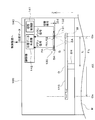
- the servo system S includes a servo motor SM and a control device CT.
- the servo motor SM includes an encoder 100 and a motor M.
- the motor M is an example of a power generation source that does not include the encoder 100. Although the motor M alone may be referred to as a servo motor, in this embodiment, a configuration including the encoder 100 is referred to as a servo motor SM.
- the motor M has a shaft SH that is an example of a moving body, and outputs a rotational force by rotating the shaft SH around the axis AX.
- the motor M is not particularly limited as long as it is a motor controlled based on data detected by the encoder 100 such as position data.
- the motor M is not limited to an electric motor that uses electricity as a power source.
- the motor M is a motor using another power source such as a hydraulic motor, an air motor, or a steam motor. There may be. However, for convenience of explanation, a case where the motor M is an electric motor will be described below.
- the encoder 100 is connected to the shaft SH on the opposite side to the rotational force output side of the motor M.
- the encoder 100 detects the position (angle) of the shaft SH, thereby detecting the position x (also referred to as the rotation angle ⁇ ) of the motor M (an example of a measurement target), and position data representing the position x. Output.
- the encoder 100 includes, in addition to or instead of the position x of the motor M, a speed v (also referred to as rotational speed, angular velocity, etc.) of the motor M and an acceleration a (also referred to as rotational acceleration, angular acceleration, etc.) of the motor M. At least one may be detected.
- the speed v and acceleration a of the motor M are detected by processing such as, for example, differentiating the position x by the first or second order with respect to time or counting a detection signal (for example, an incremental signal described later) for a predetermined time. Is possible. For convenience of explanation, the following description will be made assuming that the physical quantity detected by the encoder 100 is the position x.
- the control device CT acquires the position data output from the encoder 100, and controls the rotation of the motor M based on the position data. Therefore, in this embodiment in which an electric motor is used as the motor M, the control device CT controls the rotation of the motor M by controlling the current or voltage applied to the motor M based on the position data. . Furthermore, the control device CT obtains a host control signal from a host control device (not shown), and a rotational force capable of realizing the position and the like represented by the host control signal is output from the shaft SH of the motor M. Thus, it is possible to control the motor M. When the motor M uses another power source such as a hydraulic type, an air type, or a steam type, the control device CT controls the rotation of the motor M by controlling the supply of these power sources. Is possible.
- the encoder 100 according to the present embodiment includes a disk 110, an optical module 130, and a control unit 140.
- the vertical direction and the like are determined as follows. That is, in FIG. 2, the direction in which the disk 110 faces the optical module 130, that is, the Z-axis positive direction is represented as “up”, and the opposite Z-axis negative direction is represented as “down”.
- the positional relationship between the components of the encoder 100 according to the present embodiment is not particularly limited to concepts such as up and down.
- other directions may be used for the directions determined here, or directions other than these may be used while being described as appropriate.
- the disk 110 is formed in a disk shape, and is arranged such that the disk center O substantially coincides with the axis AX.
- the disk 110 is connected to the shaft SH of the motor M, and is rotated by the rotation of the motor M, that is, the rotation of the shaft SH.
- a disk-shaped disk 110 is described as an example of an object to be measured (also referred to as a moving body) for measuring the rotation of the motor M.
- an object to be measured also referred to as a moving body
- these members can also be used as non-measuring objects.
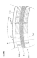
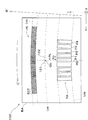
- the disk 110 has a plurality of slit arrays SA and SI as shown in FIG. As described above, the disk 110 rotates with the driving of the motor M.
- the optical module 130 is fixedly disposed so as to face a part of the disk 110. Therefore, the slit arrays SA and SI and the optical module 130 are mutually in the circumferential direction of the disk 110 (in the direction of arrow C shown in FIG. 3; hereinafter referred to as “disk circumferential direction C” as appropriate) as the motor M is driven. It is arranged so that relative movement is possible.
- the optical module 130 is arranged on the upper surface side of the disk 110 so as to face a part of the slit arrays SA and SI to constitute an optical detection mechanism. This optical detection mechanism will be described in detail.
- the optical detection mechanism includes slit arrays SA and SI and an optical module 130.
- the slit array is formed as a track arranged in a ring shape centered on the disk center O on the upper surface of the disk 110.
- the slit array has a plurality of reflective slits (hatched portions in FIG. 4) arranged along the disk circumferential direction C over the entire circumference of the track. Each reflection slit reflects light emitted from the light sources 131 and 132.
- the disk 110 is made of glass, for example.
- the reflective slit of the slit array can be formed by applying a light reflecting member to the surface of the glass disk 110.
- the material of the disk 110 is not limited to glass, and metal, resin, or the like can be used.
- the reflective slit uses a metal having a high reflectance as the disk 110, and a portion that does not reflect light is roughened by sputtering or the like, or a material having a low reflectance is applied, thereby reducing the reflectance. It may be formed by lowering.
- the material and manufacturing method of the disk 110 are not particularly limited.
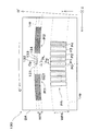
- FIG. 4 shows a partially enlarged view near the area Area in FIG.
- the slit array SA (corresponding to an example of the first slit array) is arranged on the inner diameter side of the two slit arrays, while the slit array SI (corresponding to an example of the second slit array) is It is arranged on the outer diameter side.
- the plurality of reflective slits included in the slit array SA are arranged on the entire circumference of the disk 110 so as to have an absolute pattern in the disk circumferential direction C.
- Each reflection slit of the slit array SA has an end Eg in the disk circumferential direction C located in a region where the plurality of reflection slits of the slit array SI does not exist in the disk circumferential direction C (substantially central region between the slits). So that it is formed.
- the absolute pattern is a pattern in which the position and ratio of reflection slits within an angle at which a light receiving array included in an optical module 130 (to be described later) faces are uniquely determined within one rotation of the disk 110. That is, when the motor M is at a certain position x, the combination of detection or non-detection of the plurality of light receiving elements of the opposed light receiving array (on / off bit pattern by detection) is the absolute value of the position x. (Absolute position, Absolute position) is expressed uniquely.
- various algorithms can be used as long as the absolute position of the motor M can be generated one-dimensionally by a bit of the number of light receiving elements of the light receiving array.
- the absolute position detection accuracy decreases.
- two light sources 131 and 132 are provided in the optical module 130, and irradiation by each light source is switched. Details of this will be described later.
- the plurality of reflective slits included in the slit array SI are arranged on the entire circumference of the disk 110 so as to have an incremental pattern in the disk circumferential direction C.
- the incremental pattern is a pattern that is regularly repeated at a predetermined pitch.
- This incremental pattern is different from an absolute pattern that represents the absolute position x with the presence / absence of detection by a plurality of light receiving elements as bits, and the motor M within each pitch or within one pitch depending on the sum of the detection signals by at least one light receiving element. Represents the position. Therefore, the incremental pattern does not represent the absolute position x of the motor M, but can represent the position with very high accuracy compared to the absolute pattern.
- the optical module 130 is formed as a substrate BA parallel to the disk 110, and is fixed while facing part of the slit arrays SA and SI of the disk 110. Therefore, as the disk 110 rotates, the optical module can move relative to the slit arrays SA and SI in the disk circumferential direction C.
- the optical module 130 is formed as a substrate BA capable of reducing the thickness of the encoder 100 or facilitating manufacturing.
- the optical module 130 is not necessarily configured in a substrate shape. There is no need.
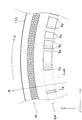
- the optical module 130 has two light sources 131 and 132 and light receiving arrays PA, PI1, and PI2 on the surface of the substrate BA facing the disk 110.
- the light sources 131 and 132 are formed on the lower surface of the substrate BA (surface in the negative Z-axis direction), that is, the surface in the slit array facing direction, in the direction corresponding to the disk circumferential direction C (the direction of the arrow C ′ shown in FIG. (It is described as “module circumferential direction C ′”).
- the light sources 131 and 132 irradiate light to a part of the two slit arrays SA and SI (for example, the area Area, also referred to as “irradiation area”) that pass through the opposing positions.
- the irradiation by the light source 131 and the irradiation by the light source 132 are switched and are not performed simultaneously.
- the light source 131 corresponds to an example of one light source
- the light source 132 corresponds to an example of another light source.
- These light sources 131 and 132 are not particularly limited as long as they are light sources capable of irradiating light to an irradiation region.
- LEDs Light Emitting Diodes
- the light sources 131 and 132 are formed as point light sources in which an optical lens or the like is not particularly disposed, and irradiates diffuse light from the light emitting unit.
- a point light source it is not necessary to be an exact point, and light can be emitted from a finite surface as long as it can be considered that diffuse light is emitted from a substantially point-like position in terms of design and operation principle. Needless to say.
- the light sources 131 and 132 can pass through two opposing positions, although there are some effects such as a change in the amount of light due to deviation from the optical axis and attenuation due to a difference in optical path length. Since each portion of the slit arrays SA and SI can be irradiated with diffused light, it is possible to irradiate these portions almost uniformly. In addition, since condensing and diffusing by the optical element are not performed, errors due to the optical element are less likely to occur, and the straightness of the irradiation light to the slit array can be improved.
- the light receiving array is disposed around the light source 131 on the surface of the substrate BA facing the slit array, and receives the reflected light from the facing slit array.
- the light receiving array has a plurality of light receiving elements (dot hatched portions, light receiving elements P0 to P4, etc.).
- the plurality of light receiving elements forming the light receiving array are arranged along the module circumferential direction C ′ as shown in FIG.
- the module circumferential direction C ′ in the optical module 130 has a shape in which the disk circumferential direction C in the disk 110 is projected onto the optical module 130. That is, the light receiving array receives light emitted from the light sources 131 and 132 and reflected by the slit array of the disk 110, and light emitted from the light sources 131 and 132 is diffused light. Therefore, the image of the slit array projected onto the optical module 130 is enlarged by a predetermined enlargement factor ⁇ corresponding to the optical path length. That is, as shown in FIGS.
- the length of each of the slit arrays SA and SI in the disk radial direction R is WSA and WSI, and the reflected light is projected onto the optical module 130 in the disk radial direction.
- the length of the direction corresponding to R (the direction of the arrow R ′ shown in FIG. 5; hereinafter referred to as “module radial direction R ′” as appropriate) is WPA and WPI, WPA and WPI are ⁇ of WSA and WSI. Double the length.
- the module circumferential direction C ′ is also projected onto the optical module 130 and has a shape affected by the magnification factor ⁇ .
- the module circumferential direction C ′ at the positions of the light sources 131 and 132 will be described as a specific example.
- the disk circumferential direction C in the disk 110 is circular with the axis AX as the center.
- the center of the module circumferential direction C ′ projected onto the optical module 130 is irradiated with light from the light sources 131 and 132, so that the light source is an in-plane position of the disk 110 on which the light sources 131 and 132 are disposed.
- the apparent distance L between the axial center AX and the optical center Op is a position separated from the reference by a distance ⁇ L enlarged by an enlargement factor ⁇ .
- the module circumferential direction C ′ in the optical module 130 is centered on the measurement axis center Os separated from the optical center Op by a distance ⁇ L in the axis AX direction on the line where the optical center Op and the axis AX ride. It is on a line whose radius is the distance ⁇ L.
- the correspondence between the disk circumferential direction C and the module circumferential direction C ′ is represented by arcuate lines Lcd and Lcp.
- a line Lcd shown in FIG. 4 represents a line along the disk circumferential direction C on the disk 110
- a line Lcp shown in FIG. 5 represents a line along the module circumferential direction C ′ on the substrate BA (the line Lcd is optical). Represents a line reflected on the module 130.
- each light receiving element for example, PD (Photodiode) can be used.
- the light receiving element is not limited to the PD, and is not particularly limited as long as it can receive the light emitted from the light sources 131 and 132 and convert it into an electric signal.
- almost two light receiving arrays are arranged corresponding to the two slit arrays SA and SI (light receiving arrays PA, PI1, PI2).
- the light receiving array PA corresponds to the slit array SA
- the light receiving arrays PI1 and PI2 correspond to the slit array SI.
- the light receiving arrays PI1 and PI2 are divided in the middle, but are arranged on the same track (that is, on the same circumference), and therefore are counted as one here. Further, the number of light receiving arrays corresponding to one slit array is not limited to one, and a plurality of light receiving arrays may be arranged.
- the light sources 131 and 132, the light receiving array PA for absolute signals, and the light receiving arrays PI1 and PI2 for incremental signals are arranged in the positional relationship shown in FIG.
- the light receiving array PA for absolute signals (corresponding to an example of the first light receiving array) is connected to the light sources 131 and 132 in the module radial direction R ′ within the plane of the substrate BA parallel to the slit array SA. On the other hand, it is arranged at a position offset to the inner diameter side (or the outer diameter side).
- the plurality of light receiving elements of the light receiving array PA are arranged at a constant pitch along the module circumferential direction C ′ (more precisely, the line Lcp). Therefore, each light receiving element group of the light receiving array PA receives the reflected light from the slit array SA, thereby generating an absolute signal having a bit pattern corresponding to the number of light receiving elements.
- FIG. 5 the light receiving array PA for absolute signals
- the light receiving arrays PI1 and PI2 for the incremental signals are provided on one side and the other side of the light sources 131 and 132 in the module circumferential direction C ′ within the plane of the substrate BA parallel to the slit array SI. Placed in both.
- the light sources 131 and 132 are arranged at positions in the ink receiving arrays PI1 and PI2 arranged as one track in the module circumferential direction C ′.
- the light receiving array PA corresponding to the absolute pattern has, for example, nine light receiving elements.
- each light reception or non-light reception is treated as a bit and represents a 9-bit absolute position x. Therefore, the light reception signals received by each of the plurality of light receiving elements are handled independently of each other by the position data generation unit 142 of the control unit 140 and are encoded (encoded) into a serial bit pattern. Are decoded from a combination of these received light signals.
- the light receiving signal of this light receiving array PA is called “absolute signal” or abbreviated as “absolute signal”.
- the light receiving arrays PI1 and PI2 (corresponding to an example of the second light receiving array) corresponding to the incremental pattern have a plurality of light receiving elements arranged on the line Lcp corresponding to the same slit array SI.
- the light receiving array will be described by taking the light receiving array PI1 as an example.
- a total of four sets of light receiving elements are arranged in one pitch of the incremental pattern (one pitch in the projected image, which is the same as the pitch Pm shown in FIG. 5).
- a plurality of sets of light receiving elements are further arranged along the module circumferential direction C ′.
- reflection slits are repeatedly formed for each pitch. Therefore, when the disk 110 rotates, each light receiving element generates a periodic signal of one cycle (referred to as 360 ° in electrical angle) at one pitch. To do. Since four light receiving elements are arranged in one set corresponding to one pitch, adjacent light receiving elements in one set detect periodic signals having a phase difference of 90 ° from each other. .
- the received light signals are divided into an A phase signal, a B phase signal (a phase difference of 90 ° with respect to the A phase signal), an A bar phase signal (a phase difference of 180 ° with respect to the A phase signal), and a B bar phase signal (with respect to the B phase signal).
- the phase difference is called 180 °).
- the signal of each phase in one set and the signal of each phase in the other set corresponding to it have values that change similarly. Accordingly, signals of the same phase are added over a plurality of sets. Accordingly, four signals whose phases are shifted by 90 ° are detected from the many light receiving elements of the light receiving array PI1 shown in FIG.
- the light receiving array PI2 is configured similarly to the light receiving array PI1. Accordingly, four signals whose phases are shifted by 90 ° are generated from the light receiving arrays PI1 and PI2. These four signals are called “incremental signals” or abbreviated as “incremental signals”.
- the light receiving arrays PI1 and PI2 correspond to an example of a second light receiving array.
- one set corresponding to one pitch of the incremental pattern includes four light receiving elements, and each of the light receiving arrays PI1 and PI2 has a plurality of similar sets.
- the number of light receiving elements in one set is not particularly limited, and the light receiving array PI1 and the light receiving array PI2 may be configured to acquire light receiving signals having different phases.
- the light source 131 is disposed at a position that substantially coincides with the center position of the light receiving array PA (in this example, the center position of the light receiving element P0) in the module circumferential direction C ′. Is done.
- the light source 132 is arranged in parallel with the first light source 131 along the module circumferential direction C ′.
- the light source 131 is referred to as “first light source 131” and the light source 132 is referred to as “second light source 132” as appropriate.
- the first light source 131 and the second light source 132 are arranged to be shifted in the module circumferential direction C ′ by the pitch PL.
- This pitch PL is expressed by the following (formula 2) using the gap length G and the protrusion amount ⁇ d when the pitch in the module circumferential direction C ′ of each light receiving element in the light receiving array PA is Pm (corresponding to an example of the pitch P). ).
- PL Pm / 2 ⁇ (G ⁇ d) / G (Formula 2)
- the pitch PL is substantially equal to the half pitch (Pm / 2) as can be seen from the above (Formula 2).
- the pitch PL is a half pitch (Pm / 2) corresponding to this case.
- the two light sources 131 and 132 are arranged in parallel by being shifted by a half pitch (Pm / 2) in the module circumferential direction C ′, and therefore, the absolute signal (first signal of the light receiving array PA by the light from the first light source 131).
- a phase difference can be provided between an absolute signal (corresponding to an example of a light reception signal) and an absolute signal (corresponding to an example of a second light reception signal) of the light reception array PA by light from the second light source 132.
- the electrical angle is 180 °.
- each reflection slit of the slit array SA has its end portion Eg located in a region between the slits of the slit array SI.
- each light receiving element of the light receiving array PA is not positioned opposite to the end EG of the reflection slit. Therefore, when the position in one pitch by the incremental signal from the light receiving arrays PI1 and PI2 is a region where the reflection slit exists, the absolute position by the absolute signal from the light receiving array PA corresponds to the change of the bit pattern. Absent.
- the absolute position by the absolute signal from the light receiving array PA may correspond to the change of the bit pattern.
- the irradiation of the second light source 132 is performed when the position in one pitch based on the incremental signal from the light receiving arrays PI1 and PI2 when the first light source 131 is irradiated corresponds to a region where there is no reflection slit.
- the incremental signal from the light receiving arrays PI1 and PI2 is a substantially sinusoidal periodic signal having one cycle at one pitch (360 ° in electrical angle). By changing the phase by 180 ° in terms of electrical angle, the position in one pitch can be changed to a region where the reflection slit exists.
- the absolute signal from the light receiving array PA when the first light source 131 is irradiated corresponds to the change of the bit pattern
- the absolute signal from the light receiving array PA when the second light source 132 is irradiated is obtained.
- the phase difference of each absolute signal when the first light source 131 or the second light source 132 is irradiated is an electrical angle of 180 ° corresponding to a half pitch of the incremental pattern. It is not a thing. For example, it may be an odd multiple of 0.5 pitch, such as 1.5 pitch (electrical angle 540 °) or 2.5 pitch (electrical angle 900 °). Furthermore, it is not always necessary to set the half pitch to an odd multiple, and the phase difference may be increased or decreased within a range in which the position in one pitch can be changed from an area where no reflection slit exists to an existing area.
- the phase difference is an odd multiple of 0.5 pitch.
- region which can exist can be improved. Therefore, it can be said that the two light sources 131 and 132 may be arranged so as to be shifted by (n + 0.5) Pm in the module circumferential direction C ′, where n is a natural number including 0.
- the two light sources 131 and 132 should be shifted by ⁇ (n + 0.5) Pm ⁇ (G ⁇ d) / G ⁇ . That's fine. If the distance between the two light sources 131 and 132 is increased, the amount of light received by the light receiving arrays PI1 and PI2 and the light receiving array PA when the second light source 131 is irradiated is not uniform in the module circumferential direction C ′. The above characteristics are degraded. Therefore, it can be said that it is most preferable to dispose the two light sources 131 and 132 by shifting by the smallest value satisfying (n + 0.5) Pm, that is, by a half pitch (Pm / 2) as in this embodiment.
- the control unit 140 includes a switching control unit 141 and a position data generation unit 142.
- the switching control unit 141 controls switching between irradiation of the first light source 131 and irradiation of the second light source 132. Further, the switching control unit 141 determines whether or not to switch the irradiation of the first light source 131 to the irradiation of the second light source 132 based on the incremental signal from the light receiving arrays PI1 and PI2 when the first light source 131 is irradiated. .
- the switching control unit 141 first irradiates the first light source 131 at the timing of measuring the position x of the motor M (for example, when the encoder 100 is turned on).
- the position data generation unit 142 acquires each light receiving signal (A phase signal, B phase signal, A bar phase signal, B bar phase signal) from the set of four light receiving elements of the light receiving arrays PI1, PI2 at that time. .
- the switching control unit 141 acquires a specific signal (for example, a B-phase signal) among the received light signals from the position data generation unit 142, and for example, its output amplitude is higher than a predetermined threshold (hereinafter, the signal is In the case of “H”), it is determined that the position in one pitch of the disk 110 is an area where the reflection slits of the slit array SI are present, and it is determined that switching of the light source is unnecessary.
- the position data generation unit 142 detects the absolute position based on the absolute signal from the light receiving array PA by the irradiation of the first light source 131, and also the first light source. The relative position from the absolute position is detected based on the incremental signal from the light receiving arrays PI1 and PI2 due to the irradiation of 131.
- the switching control unit 141 has an output amplitude of a specific signal (for example, a B-phase signal) acquired from the position data generation unit 142 when the first light source 131 is irradiated, which is lower than a predetermined threshold (hereinafter, referred to as “a”).
- a a predetermined threshold
- the switching control unit 141 switches the irradiation of the first light source 131 to the irradiation of the second light source 132, and the position data generation unit 142 detects the absolute position based on the absolute signal from the light receiving array PA at that time. Thereafter, the switching control unit 141 switches the irradiation of the second light source 132 to the irradiation of the first light source 131 again, and the position data generation unit 142 starts from the absolute position based on the incremental signals from the light receiving arrays PI1 and PI2 at that time. The relative position of is detected.
- the light receiving arrays PI1 and PI2 of the optical module 130 are returned to the irradiation by the first light source 131 when acquiring the incremental signal so that the correct position can be detected by the irradiation by the first light source 131 at the intermediate position. This is because the detection position is shifted by a half pitch (Pd / 2) in the irradiation by the second light source 132 arranged by being shifted by a half pitch (Pm / 2).
- the position data generation unit 142 acquires from the optical module 130 an absolute signal of a bit pattern representing the absolute position x and four incremental signals whose phases are shifted by 90 °. Then, based on the acquired signals, the position data generation unit 142 calculates the position x of the motor M represented by these signals, and outputs the position data representing the position x to the control device CT.
- the position data generation method by the position data generation unit 142 is not particularly limited because various methods can be used.
- the absolute position is detected based on the absolute signal, and the relative position from the absolute position is detected based on the incremental signal, but for example, the absolute position can be determined with higher accuracy using both the incremental signal and the absolute signal. You may make it detect.
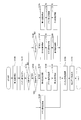
- control unit 140 starts the procedure shown in the flowchart of FIG. 6 at the timing of measuring the position x of the motor M (for example, when the encoder 100 is turned on).
- step S ⁇ b> 10 the control unit 140 supplies current to the first light source 131 by the switching control unit 141 to irradiate the first light source 131.
- the light from the first light source 131 is applied to the slit arrays SA, SI, and the reflected light from the slit arrays SA, SI is received by the light receiving elements of the light receiving arrays PA, PI1, PI2.
- step S20 the control unit 140 causes the position data generation unit 142 to receive each light reception signal (A phase signal, B phase signal, A bar phase signal, etc.) from the set of four light receiving elements included in the light receiving arrays PI1 and PI2. B-bar phase signal) is acquired. And the switching control part 141 acquires the specific signal (for example, B phase signal) among those received light signals.
- each light reception signal A phase signal, B phase signal, A bar phase signal, etc.
- B-bar phase signal is acquired.
- the switching control part 141 acquires the specific signal (for example, B phase signal) among those received light signals.
- step S30 the control unit 140 determines whether the signal acquired in step S20 is “H” by the switching control unit 141. If it is determined that the signal is “H” (YES in step S30), the process proceeds to step S40.
- step S ⁇ b> 40 the control unit 140 acquires the absolute signal from the light receiving array PA by the irradiation of the first light source 131 by the position data generation unit 142. Then, it progresses to below-mentioned step S80.
- step S30 determines whether the signal is “L” (NO in step S30).
- step S50 the control unit 140 causes the switching control unit 141 to stop the supply of current to the first light source 131 and turn it off, and supply the current to the second light source 132 to irradiate the second light source 132. Thereby, the irradiation by the first light source 131 is switched to the irradiation by the second light source 132.
- step S60 the control unit 140 uses the position data generation unit 142 to acquire an absolute signal from the light receiving array PA by the irradiation of the second light source 132.
- step S ⁇ b> 70 the control unit 140 causes the switching control unit 141 to stop supplying current to the second light source 132 and turn it off, and supply current to the first light source 131 to irradiate the first light source 131. . Thereby, the irradiation by the first light source 131 is switched again from the irradiation by the second light source 132.
- step S80 the control unit 140 causes the position data generation unit 142 to acquire an incremental signal from the light receiving arrays PI1 and PI2 by the irradiation of the first light source 131.
- step S90 the control unit 140 causes the position data generation unit 142 to determine the position x of the motor M represented by these signals based on the absolute signal and the incremental signal acquired in step S40 or step S60 and step S80.
- the position data representing the position x is calculated and output to the control device CT. This flow is completed by the above.
- the optical module 130 has two light sources 131 and 132, and the two light sources 131 and 132 are arranged in parallel in the module circumferential direction C ′.
- a phase difference can be provided between the absolute signal of the light receiving array PA by the light from the first light source 131 and the absolute signal of the light receiving array PA by the light from the second light source 132.
- the disk 110 has a predetermined length in the disk circumferential direction C (for example, 1 pitch Pd of an incremental pattern). Or two slit arrays SA1 and SA2 that are offset by 1/2), or although not shown, the slit arrays SA1 and SA2 are not offset from each other and correspond to the two slit arrays SA1 and SA2, respectively.
- a configuration in which the received light arrays PA1 and PA2 are offset to obtain received light signals having different phases is conceivable.
- the two slit arrays SA1 and SA2 on the disk and to provide the two light receiving arrays PA1 and PA2 corresponding to the slit array SA1 and SA2 in the optical module 130, which increases the size of the encoder 100.
- the slit array SA and the light receiving array PA can be configured one by one. Therefore, the disk 110 and the optical module 130 (particularly, compared to the above configuration). The size in the module radial direction R ′) can be greatly reduced.
- a processing circuit such as a comparator for the absolute signal is also required for each of the light receiving arrays PA1 and PA2 in the comparative example, but in the present embodiment, it may be provided only for the light receiving array PA. Therefore, it is possible to reduce the size while improving the detection accuracy of the encoder 100, and it is possible to reduce the number of parts and reduce the manufacturing cost.
- the first light source 131 is disposed at a position that substantially coincides with the center position of the light receiving array PA and the intermediate position of the light receiving arrays PI1 and PI2 in the module circumferential direction C ′.
- the first light source 131 and the first light source 131 are arranged in parallel along the module circumferential direction C ′. Due to the arrangement of the first light source 131, the amount of light received by the light receiving arrays PI1 and PI2 and the light receiving array PA is equal in the module circumferential direction C ′ compared to the second light source 132, and the characteristics of the light amount distribution are good. Therefore, by using the first light source 131 as a main light source and using the second light source 132 as an auxiliary light source that switches as necessary as in the present embodiment, it is possible to suppress a decrease in detection accuracy.
- whether the irradiation of the first light source 131 is switched to the irradiation of the second light source 132 based on the incremental signal from the light receiving arrays PI1 and PI2 when the control unit 140 irradiates the first light source 131. Determine whether or not.
- the received light signal from the light receiving array PA is not a change point of the bit pattern and it is not necessary to switch the irradiation of the first light source 131 and the second light source 132, it is controlled not to switch the light source. Therefore, unnecessary switching control can be prevented and reliability can be improved.
- the position of the disk 110 is detected with high accuracy using the incremental signal and it is determined whether or not the light source is switched, it is accurately determined whether or not the light reception signal from the light reception array PA is a bit pattern change point. Can be determined.
- the light receiving array PA is arranged at a position offset with respect to the first light source 131 and the second light source 132 in a direction corresponding to the module radial direction R ′. Arranged on one side and the other side of the first light source 131 and the second light source 132 in the circumferential direction C ′.
- the arrangement of the light receiving arrays PI1, PI2, PA can be made to correspond to a substantially concentric light quantity distribution centered on the first light source 131 and the second light source 132, thereby increasing the light receiving area.
- the reflected light from the slit arrays SI and SA can be used effectively.
- the ink-receiving arrays PI1 and PI2 for ink can be arranged close to the light sources 131 and 132, so that the apparatus can be miniaturized.
- the number of light sources is particularly two. Thereby, compared with the case where the number of light sources described later is four, the number of light sources is small, so that the cost is low and the number of times of switching the light sources can be reduced, so even if the processing speed of the switching control unit 141 is slow. It has the effect of being sufficient.
- the switching of the light source is performed once. It may be made to become.
- control content of the control unit 140 provided in the encoder 100 according to this modification will be described.
- the same steps as those in FIG. 6 described above are denoted by the same reference numerals, and description thereof will be omitted as appropriate.
- Steps S10 to S30 and steps S50 to S60 are the same as in FIG. That is, the first light source 131 is irradiated in step S10, and a specific signal (for example, a B phase signal) among the incremental signals is acquired in step S20.
- a specific signal for example, a B phase signal
- step S30 it is determined whether or not the acquired signal is “H”. If it is “H” (YES in step S30), the irradiation from the first light source 131 to the second light source in step S50. It is switched to irradiation by 132.
- step S60 an absolute signal from the light receiving array PA is acquired.
- step S61 the control unit 140 causes the position data generation unit 142 to cause each incremental signal (A phase signal, B) from the set of four light receiving elements included in the light receiving arrays PI1 and PI2 by the irradiation of the second light source 132.
- Phase signal, A bar phase signal, B bar phase signal Phase signal, A bar phase signal, B bar phase signal.
- step S62 the control unit 140 corrects each incremental signal acquired in step S61 to each incremental signal by irradiation of the first light source 131 by the position data generating unit 142.
- the two light sources 131 and 132 are shifted in parallel by Pm / 2 in the module circumferential direction C ′, so that the incremental signals of the light receiving arrays PI1 and PI2 by the first light source 131 and the second
- the incremental signals of the light receiving arrays PI1 and PI2 by the light source 132 have a phase difference of 180 ° in electrical angle corresponding to a half pitch of the incremental pattern.
- step S90 the control unit 140 determines the position x of the motor M represented by these signals based on the absolute signal acquired in step S60 and the incremental signal corrected in step S62 by the position data generation unit 142.
- the position data representing the position x is calculated and output to the control device CT. This flow is completed by the above.
- the light source can be switched once, the time required for switching the light source can be shortened compared to the above embodiment. As a result, it is possible to suppress detection errors caused by the rotation of the shaft SH (disk 110) during the switching of the light sources.
- each reflection slit included in the slit array SA has an end portion Eg in the disk circumferential direction C and a plurality of reflection slits included in the slit array SI in the disk circumferential direction C. It is formed so that it may be located in the area to be.
- the absolute position by the absolute signal from the light receiving array PA corresponds to the change of the bit pattern. There is no.
- the absolute position by the absolute signal from the light receiving array PA may correspond to the change of the bit pattern.
- the switching control unit 141 determines that the specific signal (for example, the B phase signal) acquired from the position data generation unit 142 when the first light source 131 is irradiated is “H”.
- the position of 110 in one pitch is regarded as an area where the reflection slits of the slit array SI exist, and it is determined that the light source needs to be switched, and the irradiation is switched to the irradiation of the second light source 132.
- a specific signal for example, a B phase signal
- the position in one pitch of the disk 110 is an area where there is no reflection slit of the slit array SI. Therefore, it is determined that it is not necessary to switch the light source, and the light source is not switched.
- the disk 110 of this modification has two slit arrays SA and SI.
- the plurality of reflective slits included in the slit array SA have an absolute pattern in the disk circumferential direction C, and are arranged on the inner diameter side in this example.
- the plurality of reflective slits included in the slit array SI have an incremental pattern in the disk circumferential direction C, and are arranged on the outer diameter side in this example.
- the end Eg of each reflective slit included in the slit array SA is located in a region where the plurality of reflective slits included in the slit array SI do not exist (region between the slits) in the disk circumferential direction C as in the above-described embodiment. It is.
- the optical module 130 of this modification is provided with light receiving arrays PA and PI in the module radial direction R ′ of the light sources 131 and 132. That is, the light receiving arrays PA and PI are arranged at positions offset in different directions with respect to the light sources 131 and 132 in the module radial direction R ′ within the plane of the substrate BA parallel to the slit arrays SA and SI.
- These light receiving arrays PA and PI correspond to the two slit arrays SA and SI, respectively, the light receiving array PA corresponds to the slit array SA, and the light receiving array PI corresponds to the slit array SI.
- the light receiving array PI for an incremental signal has a plurality of light receiving elements arranged on a line Lcp corresponding to the slit array SI.
- the light receiving array PI is configured as one continuous light receiving array, and a plurality of sets (SET) of the four light receiving elements described above are arranged along the module circumferential direction C ′.
- the light receiving array PA for absolute signals has a plurality of light receiving elements (9 in this example) arranged at a constant pitch along the line Lcp corresponding to the slit array SA.
- first light source 131 and the second light source 132 are arranged so as to be shifted in the module circumferential direction C ′ by Pm / 2, as in the above-described embodiment.
- each slit of the slit arrays SA and SI is formed as a transmission hole, or a portion other than the slit is formed by roughening by sputtering or applying a material having low transmittance. May be. Even when such a transmissive encoder is used, the same effect as that of the above-described embodiment is obtained.
- the optical module 130 in the present embodiment includes the light sources 131 and 132 and the light receiving arrays PA, PI1, and PI2, but is not necessarily formed integrally as in the present embodiment.
- PI1 and PI2 are formed separately, as in the case where the light sources 131 and 132 and the light receiving arrays PA, PI1 and PI2 are formed separately, such as in the case of being transmissive and disposed across the disk 110, Both are included.
- the optical module 130 has four light sources 131, 132, 133, and 134 arranged in parallel along the module circumferential direction C ′.
- the light source 131 is described as “first light source 131”
- the light source 132 is described as “second light source 132”
- the light source 133 is referred to as “third light source 133”
- the light source 134 is referred to as “fourth light source”. 134 ".
- the third light source 133 and the fourth light source 134 correspond to examples of other light sources.
- the first light source 131 is disposed at a position substantially coincident with the center position of the light receiving array PA in the module circumferential direction C ′.
- the intervals between the light sources 131, 132, 133, and 134 are the pitch PL.
- the pitch PL in the present modification is as follows using the gap length G and the protrusion amount ⁇ d when the pitch in the module circumferential direction C ′ of each light receiving element in the light receiving array PA is Pm (corresponding to an example of the pitch P). It is shown by (Formula 3).
- PL Pm / 4 ⁇ (G ⁇ d) / G (Formula 3)
- the pitch PL is substantially equal to 1 ⁇ 4 pitch (Pm / 4) as can be seen from the above (Formula 3).
- the pitch PL is 1 ⁇ 4 pitch (Pm / 4) corresponding to this case.
- the four light sources 131, 132, 133, and 134 are arranged in parallel by being shifted by a quarter pitch (Pm / 4) in the module circumferential direction C ′.
- a phase difference can be provided in the absolute signal of the light receiving array PA by light. That is, with respect to the absolute signal from the first light source 131, the phase difference of the absolute signal from the second light source 132 is 1 ⁇ 4 pitch (90 ° in electrical angle) of the incremental pattern, and the phase difference of the absolute signal from the third light source 133 is 1. / 2 pitch (180 ° in electrical angle), the phase difference of the absolute signal by the fourth light source 134 is 3/4 pitch (270 ° in electrical angle).
- the switching control unit 141 performs control as follows.
- the switching control unit 141 first irradiates the first light source 131 at the timing of measuring the position x of the motor M (for example, when the encoder 100 is turned on).
- the position data generation unit 142 acquires each light receiving signal (A phase signal, B phase signal, A bar phase signal, B bar phase signal) from the set of four light receiving elements of the light receiving arrays PI1, PI2 at that time.
- the switching control unit 141 acquires a specific signal (for example, an A phase signal and a B phase signal) from the received light signals from the position data generation unit 142, and both the A phase signal and the B phase signal are “H”.
- the position in one pitch of the disk 110 is an area where the reflection slits of the slit array SI are present (here, substantially the central area of the reflection slits), and it is determined that switching of the light source is unnecessary.
- the switching control unit 141 since the switching control unit 141 does not switch the light source, the position data generation unit 142 detects the absolute position based on the absolute signal from the light receiving array PA by the irradiation of the first light source 131, and also the first light source. The relative position from the absolute position is detected based on the incremental signal from the light receiving arrays PI1 and PI2 due to the irradiation of 131.
- the switching control unit 141 1 of the disk 110 when at least one of the A-phase signal and the B-phase signal acquired from the position data generation unit 142 when the first light source 131 is irradiated is “L”, the switching control unit 141 1 of the disk 110. It is determined that the position in the pitch is a region where the reflective slit of the slit array SI does not exist (including a boundary portion between the region where the reflective slit exists and the region where the reflective slit does not exist), and that it is necessary to switch the light source. In this modification, when the A-phase signal is “L” and the B-phase signal is “H”, the phase difference from the case where both the A-phase signal and the B-phase signal are “H” is the incremental pattern.
- the switching control unit 141 switches the irradiation of the first light source 131 to the irradiation of the second light source 132.
- the phase difference from the case where both the A-phase signal and the B-phase signal are “H” is 1 ⁇ 2 pitch (180 electrical degrees). Therefore, the irradiation of the first light source 131 is switched to the irradiation of the third light source 133.
- the phase difference from the case where both the A phase signal and the B phase signal are “H” is 3/4 pitch (electrical).
- irradiation with the first light source 131 is switched to irradiation with the fourth light source 134.
- the position data generator 142 detects the absolute position based on the absolute signal from the light receiving array PA at that time. Thereafter, the switching control unit 141 switches to the irradiation of the first light source 131 again, and the position data generation unit 142 detects the relative position from the absolute position based on the incremental signals from the light receiving arrays PI1 and PI2 at that time.
- this modification is not limited to the case where the phase difference of each absolute signal of each light source is an electrical angle of 90 ° corresponding to a quarter pitch of the incremental pattern.
- the pitch may be 1.25 pitch (112.5 ° in electrical angle), 2.25 pitch (202.5 ° in electrical angle), or the like. That is, it can be said that the light sources 131, 132, 133, and 134 may be arranged so as to be shifted by (n + 0.25) Pm in the module circumferential direction C ′, where n is a natural number including 0.
- the four light sources 131, 132, 133, and 134 are set to ⁇ (n + 0.25) Pm ⁇ (G ⁇ d) / G ⁇ . What is necessary is just to shift and arrange.
- control unit 140 starts the procedure shown in the flowchart of FIG. 14 at the timing of measuring the position x of the motor M (for example, when the encoder 100 is turned on).
- Step S105 and Step S110 are the same as Step S10 and Step S20 shown in FIG. That is, the control unit 140 supplies current to the first light source 131 by the switching control unit 141 to irradiate the first light source 131, and sets the four light receiving elements of the light receiving arrays PI1 and PI2 by the position data generating unit 142. Each received light signal (A phase signal, B phase signal, A bar phase signal, B bar phase signal) is acquired. And the specific signal (for example, A phase signal and B phase signal) of those light reception signals is acquired.
- step S115 the control unit 140 determines whether or not the A phase signal acquired in step S110 is “H” by the switching control unit 141. If it is determined that the A-phase signal is “H” (YES in step S115), the process proceeds to step S120.
- step S120 the control unit 140 determines whether the B-phase signal acquired in step S110 is “H” by the switching control unit 141. If it is determined that the B-phase signal is “H” (YES in step S120), the process proceeds to step S125.
- step S125 the control unit 140 obtains an absolute signal from the light receiving array PA by the irradiation of the first light source 131 by the position data generation unit 142. Then, it progresses to below-mentioned step S180.
- step S120 determines whether the phase B signal is “L” (NO in step S120). If it is determined in step S120 that the phase B signal is “L” (NO in step S120), the process proceeds to step S130.
- step S130 the control unit 140 causes the switching control unit 141 to stop the supply of current to the first light source 131 and turn it off, and supply the current to the fourth light source 134 to irradiate the fourth light source 134. Thereby, the irradiation by the first light source 131 is switched to the irradiation by the fourth light source 134.
- step S135 the control unit 140 acquires an absolute signal from the light receiving array PA by the irradiation of the fourth light source 134 by the position data generation unit 142.
- step S ⁇ b> 140 the control unit 140 causes the switching control unit 141 to stop supplying the current to the fourth light source 134 and turn it off, and supply the current to the first light source 131 to irradiate the first light source 131. . Thereby, the irradiation by the fourth light source 134 is switched again to the irradiation by the first light source 131. Then, it progresses to below-mentioned step S180.
- step S115 determines whether the A-phase signal is “L” (NO in step S115). If it is determined in step S115 that the A-phase signal is “L” (NO in step S115), the process proceeds to step S145.
- step S145 the control unit 140 determines whether the B-phase signal acquired in step S110 is “H” by the switching control unit 141. If it is determined that the B-phase signal is “H” (YES in step S145), the process proceeds to step S150.
- Steps S150 to S160 are the same as steps S130 to S140. That is, the control unit 140 switches from irradiation by the first light source 131 to irradiation by the second light source 132 by the switching control unit 141, and outputs an absolute signal from the light receiving array PA by irradiation of the second light source 132 by the position data generation unit 142. get. Thereafter, the irradiation with the first light source 131 is switched again from the irradiation with the second light source 132. Then, it progresses to below-mentioned step S180.
- step S145 determines whether the B-phase signal is “L” (NO in step S145). If it is determined in step S145 that the B-phase signal is “L” (NO in step S145), the process proceeds to step S165.
- Steps S165 to S175 are the same as steps S130 to S140 described above. That is, the control unit 140 switches from irradiation by the first light source 131 to irradiation by the third light source 133 by the switching control unit 141, and outputs an absolute signal from the light receiving array PA by irradiation of the third light source 133 by the position data generation unit 142. get. Thereafter, the irradiation with the first light source 131 is switched again from the irradiation with the third light source 133.
- control unit 140 causes the position data generation unit 142 to acquire an incremental signal from the light receiving arrays PI1 and PI2 by the irradiation of the first light source 131.
- step S185 the control unit 140 causes the position data generation unit 142 to generate these signals based on the absolute signal acquired in step S125, step S135, step S155, or step S170 and the incremental signal acquired in step S180.
- a position x of the motor M to be represented is calculated, and position data representing the position x is output to the control device CT. This flow is completed by the above.
- the phase of the absolute signal can be adjusted only in units of a half pitch (electrical angle 180 °) by switching the light sources, whereas in this modification, four light sources are used. Therefore, the phase of the absolute signal can be finely adjusted in units of 1/4 pitch (electrical angle 90 °) by switching the light source.
- the phase between the absolute signal and the incremental signal is shifted for some reason, and the phase difference between the “H” or “L” switching point of the incremental signal and the bit pattern transition of the absolute signal becomes small.
- the absolute position can be calculated without using the area where the absolute signal changes, and the detection accuracy of the absolute position can be further improved.
Landscapes
- Physics & Mathematics (AREA)
- General Physics & Mathematics (AREA)
- Engineering & Computer Science (AREA)
- Microelectronics & Electronic Packaging (AREA)
- Power Engineering (AREA)
- Optical Transform (AREA)
- Transmission And Conversion Of Sensor Element Output (AREA)
Description
開示の実施形態は、エンコーダ及びサーボモータに関する。
エンコーダとして、例えば特許文献1には、モータの絶対位置を検出するエンコーダが記載されている。このエンコーダは、モータの回転シャフトに取り付けられ絶対位置検出用スリットを有する回転ディスクと、回転ディスクと対向して配置される複数個の受光素子からなる受光部と、回転ディスクを挟んで受光素子と対向して配置される発光素子と、を有する。
絶対位置検出用スリットは、互いに隣り合う任意のN個のスリットで1つのビット列を構成し、任意の回転位置を示すアドレスでの各ビット列は互いに重複しないように構成される。つまり、モータがある位置となっている場合に、対向した複数個の受光素子それぞれの検出又は未検出による組み合わせ(検出によるオン/オフのビット列)が、その位置の絶対値を一義に表すことになる。このような絶対位置検出用スリットにより絶対位置を表す場合、受光信号の検出又は未検出によるビット列の変わり目の領域において、絶対位置の検出精度が低下するという問題があった。
本発明は、このような問題に鑑みてなされたものであり、本発明の目的とするところは、検出精度を向上させつつ小型化を図ることが可能なエンコーダ及びサーボモータを提供することにある。
上記課題を解決するために、本発明のある観点によれば、ディスクの周方向に並べられた複数のスリットを有するスリットアレイと、上記スリットアレイの一部に対向しつつ、当該スリットアレイに対して上記周方向に相対移動可能な光学モジュールと、を備え、上記光学モジュールは、上記周方向に対応する方向に並列され、上記スリットアレイの一部に光を照射する2又は4個の光源と、上記スリットアレイに対し上記光源と同じ側又は反対側で当該スリットアレイの一部に対向しつつ、上記光源から照射されて上記スリットの作用を受けた光を受光する複数の受光素子が上記周方向に対応する方向に沿って並べられた受光アレイと、を有する、エンコーダが提供される。
また、上記課題を解決するために、本発明の別の観点によれば、シャフトを回転させるモータと、上記シャフトの位置を検出するエンコーダと、を備え、上記エンコーダは、上記シャフトに連結されたディスクの周方向に並べられた複数のスリットを有するスリットアレイと、上記スリットアレイの一部に対向しつつ、当該スリットアレイに対して上記周方向に相対移動可能な光学モジュールと、を備え、上記光学モジュールは、上記周方向に対応する方向に並列され、上記スリットアレイの一部に光を照射する2又は4個の光源と、上記スリットアレイに対し上記光源と同じ側又は反対側で当該スリットアレイの一部に対向しつつ、上記光源から照射されて上記スリットの作用を受けた光を受光する複数の受光素子が上記周方向に対応する方向に沿って並べられた受光アレイと、を有する、サーボモータが提供される。
本発明によれば、エンコーダの検出精度を向上させつつ小型化を図ることができる。
以下、図面を参照して、一実施形態について説明する。
なお、以下で説明する実施形態に係るエンコーダは、回転型(ロータリタイプ)や直線型(リニアタイプ)など様々なタイプのエンコーダに適用可能である。しかしながら、実施形態に係るエンコーダの理解が容易になるように、回転型のエンコーダを例に挙げて説明する。他のタイプのエンコーダに適用される場合については、移動体を回転型から直線型に変更するなど適切な変更を加えることにより可能であるため、以下における詳しい説明は省略する。
また、以下においては、「アブソリュート」及び「インクリメンタル」のことを「アブソ」及び「インクレ」と適宜略して記載する。
<1.サーボシステム>
まず、図1を参照しつつ、本実施形態に係るサーボシステムの構成について説明する。図1に示すように、本実施形態に係るサーボシステムSは、サーボモータSMと、制御装置CTとを有する。また、サーボモータSMは、エンコーダ100と、モータMとを有する。
まず、図1を参照しつつ、本実施形態に係るサーボシステムの構成について説明する。図1に示すように、本実施形態に係るサーボシステムSは、サーボモータSMと、制御装置CTとを有する。また、サーボモータSMは、エンコーダ100と、モータMとを有する。
モータMは、エンコーダ100を含まない動力発生源の一例である。このモータM単体をサーボモータという場合もあるが、本実施形態では、エンコーダ100を含む構成をサーボモータSMということにする。モータMは、移動体の一例であるシャフトSHを有し、このシャフトSHを軸心AX周りに回転させることにより、回転力を出力する。
なお、モータMは、例えば位置データ等のようなエンコーダ100が検出するデータに基づいて制御されるモータであれば特に限定されるものではない。また、モータMは、動力源として電気を使用する電動式モータである場合に限られるものではなく、例えば、油圧式モータ、エア式モータ、蒸気式モータ等の他の動力源を使用したモータであってもよい。ただし、説明の便宜上、以下ではモータMが電動式モータである場合について説明する。
本実施形態に係るエンコーダ100は、モータMの回転力出力側とは反対側のシャフトSHに連結される。そして、エンコーダ100は、シャフトSHの位置(角度)を検出することにより、モータM(測定対象の一例)の位置x(回転角度θともいう。)を検出し、その位置xを表す位置データを出力する。
エンコーダ100は、モータMの位置xに加えてか又は代えて、モータMの速度v(回転速度、角速度等ともいう。)及びモータMの加速度a(回転加速度、角加速度等ともいう。)の少なくとも一方を検出してもよい。この場合、モータMの速度v及び加速度aは、例えば、位置xを時間で1又は2階微分したり検出信号(例えば後述するインクレ信号)を所定時間の間カウントするなどの処理により検出することが可能である。説明の便宜上、以下ではエンコーダ100が検出する物理量は位置xであるとして説明する。
制御装置CTは、エンコーダ100から出力される位置データを取得して、当該位置データに基づいて、モータMの回転を制御する。従って、モータMとして電動式モータが使用される本実施形態では、制御装置CTは、位置データに基づいて、モータMに印加する電流又は電圧等を制御することにより、モータMの回転を制御する。更に、制御装置CTは、上位制御装置(図示せず)から上位制御信号を取得して、当該上位制御信号に表された位置等を実現可能な回転力がモータMのシャフトSHから出力されるように、モータMを制御することも可能である。なお、モータMが、油圧式、エア式、蒸気式などの他の動力源を使用する場合には、制御装置CTは、それらの動力源の供給を制御することにより、モータMの回転を制御することが可能である。
<2.エンコーダ>
次に、図2~図6を参照しつつ、本実施形態に係るエンコーダ100について説明する。図2に示すように、本実施形態に係るエンコーダ100は、ディスク110と、光学モジュール130と、制御部140とを有する。
次に、図2~図6を参照しつつ、本実施形態に係るエンコーダ100について説明する。図2に示すように、本実施形態に係るエンコーダ100は、ディスク110と、光学モジュール130と、制御部140とを有する。
ここで、エンコーダ100の構造の説明の便宜上、本実施形態では、上下等の方向を以下のように定める。つまり、図2において、ディスク110が光学モジュール130と面する方向、つまりZ軸正の方向を「上」と表し、逆のZ軸負の方向を「下」と表す。ただし、本実施形態に係るエンコーダ100の各構成の位置関係は、上下等の概念に特に限定されるものではない。また、説明の便宜に応じて、ここで定めた方向について他の表現等をしたり、これら以外の方向については適宜説明しつつ使用する場合もあることを付言しておく。
(2-1.ディスク)
ディスク110は、図3に示すように円板状に形成され、ディスク中心Oが軸心AXとほぼ一致するように配置される。そして、ディスク110は、モータMのシャフトSHに連結され、モータMの回転、つまりシャフトSHの回転により回転する。本実施形態では、モータMの回転を測定する被測定対象(移動体ともいう。)の例として、円板状のディスク110を例に挙げて説明するが、例えば、シャフトSHの端面などの他の部材を非測定対象として使用することも可能である。
ディスク110は、図3に示すように円板状に形成され、ディスク中心Oが軸心AXとほぼ一致するように配置される。そして、ディスク110は、モータMのシャフトSHに連結され、モータMの回転、つまりシャフトSHの回転により回転する。本実施形態では、モータMの回転を測定する被測定対象(移動体ともいう。)の例として、円板状のディスク110を例に挙げて説明するが、例えば、シャフトSHの端面などの他の部材を非測定対象として使用することも可能である。
ディスク110は、図3に示すように、複数のスリットアレイSA,SIを有する。ディスク110は上述のとおりモータMの駆動ともに回転するが、これに対して、光学モジュール130は、ディスク110の一部に対向しつつ固定配置される。従って、スリットアレイSA,SIと光学モジュール130とは、モータMの駆動に伴い、互いにディスク110の周方向(図3に示す矢印Cの方向。以下適宜「ディスク周方向C」と記載する。)で相対移動可能に配置される。
光学モジュール130は、ディスク110の上面側においてスリットアレイSA,SIの一部に対向して配置されて、光学検出機構を構成する。この光学検出機構について詳細に説明する。
(2-2.光学検出機構)
光学検出機構は、スリットアレイSA,SIと光学モジュール130とを有する。スリットアレイは、ディスク110の上面においてディスク中心Oを中心としたリング状に配置されたトラックとして形成される。スリットアレイは、トラックの全周にわたって、ディスク周方向Cに沿って並べられた複数の反射スリット(図4における斜線ハッチング部分)を有する。1つ1つの反射スリットは、光源131,132から照射された光を反射する。
光学検出機構は、スリットアレイSA,SIと光学モジュール130とを有する。スリットアレイは、ディスク110の上面においてディスク中心Oを中心としたリング状に配置されたトラックとして形成される。スリットアレイは、トラックの全周にわたって、ディスク周方向Cに沿って並べられた複数の反射スリット(図4における斜線ハッチング部分)を有する。1つ1つの反射スリットは、光源131,132から照射された光を反射する。
ディスク110は、本実施形態では例えばガラスにより形成される。そして、スリットアレイが有する反射スリットは、ガラスのディスク110の面に、光を反射する部材が塗布されることにより、形成可能である。なお、ディスク110の材質は、ガラスに限られるものではなく、金属や樹脂等を使用することも可能である。また、反射スリットは、例えば、反射率の高い金属をディスク110として使用し、光を反射させない部分を、スパッタリング等により粗面としたり反射率の低い材質を塗布したりすることで、反射率を低下させて、形成されてもよい。ただし、ディスク110の材質や製造方法等については特に限定されるものではない。
スリットアレイは、本実施形態では、ディスク110の上面においてディスク110の半径方向(図3に示す矢印Rの方向。以下適宜「ディスク径方向R」と記載する。)に2本併設される(スリットアレイSA,SI)。2本のスリットアレイSA,SIのそれぞれについてより詳細に説明するために、図3における領域Area近傍の部分拡大図を図4に示す。
図4に示すように、スリットアレイSA(第1スリットアレイの一例に相当)は、2本のスリットアレイ中内径側に配置される一方、スリットアレイSI(第2スリットアレイの一例に相当)は、外径側に配置される。スリットアレイSAが有する複数の反射スリットは、ディスク周方向Cでアブソリュートパターンを有するように、ディスク110の全周に配置される。スリットアレイSAが有する各反射スリットは、そのディスク周方向Cにおける端部Egが、ディスク周方向CにおいてスリットアレイSIが有する複数の反射スリットの存在しない領域(スリット間の略中央領域)に位置するように、形成されている。
なお、アブソリュートパターンとは、後述する光学モジュール130が有する受光アレイが対向する角度内における反射スリットの位置や割合等が、ディスク110の1回転内で一義に定まるようなパターンである。つまり、モータMがある位置xとなっている場合に、対向した受光アレイの複数の受光素子それぞれの検出又は未検出による組み合わせ(検出によるオン/オフのビットパターン)が、その位置xの絶対値(絶対位置、アブソリュートポジション)を一義に表すことになる。アブソリュートパターンの生成方法は、モータMの絶対位置を、受光アレイの受光素子数のビットにより、一次元的に表すようなパターンを生成できるものであれば、様々なアルゴリズムが使用可能である。
このようなアブソリュートパターンにより絶対位置を表す場合、受光アレイPAの各受光素子が反射スリットの端部EG近傍に対向して位置することによる、受光信号の検出又は未検出によるビットパターンの変わり目の領域において、絶対位置の検出精度が低下する。これを防止するために、本実施形態では、光学モジュール130に2つの光源131,132を設け、各光源による照射を切り替える。この詳細については後述する。
一方、スリットアレイSIが有する複数の反射スリットは、ディスク周方向Cでインクリメンタルパターンを有するように、ディスク110の全周に配置される。
インクリメンタルパターンは、図4に示すように、所定のピッチで規則的に繰り返されるパターンである。このインクリメンタルパターンは、複数の受光素子による検出の有無それぞれをビットとして絶対位置xを表すアブソリュートパターンと異なり、少なくとも1以上の受光素子による検出信号の和により、1ピッチ毎又は1ピッチ内のモータMの位置を表す。従って、インクリメンタルパターンは、モータMの絶対位置xを表すものではないが、アブソリュートパターンに比べると非常に高精度に位置を表すことが可能である。
光学モジュール130は、図2及び図3に示すように、ディスク110と平行な基板BAとして形成され、ディスク110のスリットアレイSA,SIの一部に対向しつつ固定される。従って、ディスク110の回転に伴い、光学モジュールは、スリットアレイSA,SIに対してディスク周方向Cで相対移動することができる。なお、本実施形態では、光学モジュール130がエンコーダ100を薄型化したり製造を容易にすることが可能な基板BAとして形成される場合について説明するが、光学モジュール130は、必ずしも基板状に構成される必要はない。
一方、光学モジュール130は、図2及び図5に示すように、基板BAのディスク110の対向する面上に、2つの光源131,132と、受光アレイPA,PI1,PI2とを有する。
光源131,132は、基板BAの下面(Z軸負の方向の面)、つまりスリットアレイ対向方向の面に、ディスク周方向Cに対応する方向(図5に示す矢印C′の方向。以下適宜「モジュール周方向C′」と記載する。)に沿って配置される。そして、光源131,132は、対向する位置を通過する2つのスリットアレイSA,SIの一部分(例えば領域Area、「照射領域」ともいう。)に光を照射する。なお、詳細は後述するが、光源131による照射と光源132による照射は切り替えて実施され、同時に照射されることはない。なお、光源131が一の光源の一例に相当し、光源132が他の光源の一例に相当する。
これらの光源131,132としては、照射領域に光を照射可能な光源であれば特に限定されるものではないが、例えば、LED(Light Emitting Diode)が使用可能である。そして、光源131,132は、特に光学レンズ等が配置されない点光源として形成され、発光部から拡散光を照射する。なお、点光源という場合、厳密な点である必要はなく、設計上や動作原理上、略点状の位置から拡散光が発せられるものとみなせる光源であれば、有限な面から光が発せられてもよいことは言うまでもない。このように点光源を使用することにより、光源131,132は、光軸からのズレによる光量変化や光路長の差による減衰などの影響は多少はあるにせよ、対向した位置を通過する2つのスリットアレイSA,SIのそれぞれの部分に拡散光を照射できるため、これらの部分にほぼ均等に光を照射することが可能である。また、光学素子による集光・拡散を行わないため、光学素子による誤差等が生じにくく、スリットアレイへの照射光の直進性を高める事が可能である。
受光アレイは、基板BAのスリットアレイ対向方向の面に光源131の周囲に配置され、対向するスリットアレイからの反射光を受光する。そのために、受光アレイは、複数の受光素子(ドットハッチング部分、受光素子P0~P4等。)を有する。受光アレイを形成する複数の受光素子は、図5に示すように、モジュール周方向C′に沿って並べられる。
なお、光学モジュール130におけるモジュール周方向C′は、ディスク110におけるディスク周方向Cが光学モジュール130に投影された形状となる。つまり、受光アレイは、光源131,132から照射されてディスク110のスリットアレイで反射された光を受光し、かつ、光源131,132から照射される光は拡散光である。従って、光学モジュール130上に投影されるスリットアレイの像は、光路長に応じた所定の拡大率εだけ拡大されたものとなる。つまり、図4及び図5に示すように、スリットアレイSA,SIそれぞれのディスク径方向Rの長さをWSA,WSIとし、それらの反射光が光学モジュール130に投影された形状の、ディスク径方向Rに対応する方向(図5に示す矢印R′の方向。以下適宜「モジュール径方向R′」と記載する。)の長さをWPA,WPIとすると、WPA,WPIは、WSA,WSIのε倍の長さとなる。同様に、モジュール周方向C′も、光学モジュール130に投影され、拡大率εの影響を受けた形状となる。理解が容易になるように、光源131,132の位置におけるモジュール周方向C′を例に挙げて、より具体的に説明する。ディスク110におけるディスク周方向Cは、軸心AXを中心とした円状になる。これに対して、光学モジュール130に投影されたモジュール周方向C′の中心は、光源131,132から光が照射されるため、光源131,132が配置されたディスク110の面内位置である光源中心Opを基準として、見かけ上軸心AXと光学中心Opとの間の距離Lが拡大率εで拡大された距離εLだけ、上記基準から離隔した位置となる。この位置を図2では、概念的に測定軸中心Osとして示している。従って、光学モジュール130におけるモジュール周方向C′は、光学中心Opから当該光学中心Opと軸心AXとが乗るライン上を、軸心AX方向に、距離εL離隔した測定軸中心Osを中心とし、距離εLを半径とするライン上となる。
図4及び図5では、ディスク周方向Cとモジュール周方向C′の対応関係を、円弧状のラインLcd,Lcpで表す。図4に示すラインLcdは、ディスク110上のディスク周方向Cに沿った線を表す一方、図5に示すラインLcpは、基板BA上のモジュール周方向C′に沿った線(ラインLcdが光学モジュール130上に反映された線)を表す。
なお、図2に示すように、光学モジュール130とディスク110との間のギャップ長をGとし、光源131,132の基板BAからの突出量をΔdとした場合、拡大率εは、下記(式1)で示される。
ε=(2G-Δd)/(G-Δd) …(式1)
ε=(2G-Δd)/(G-Δd) …(式1)
1つ1つの受光素子としては、例えばPD(Photodiode(フォトダイオード))を使用することができる。但し、受光素子としては、PDに限られるものではなく、光源131,132から発せられた光を受光して電気信号に変換可能なものであれば、特に限定されるものではない。
本実施形態における受光アレイは、2本のスリットアレイSA,SIに対応して、ほぼ2本配置される(受光アレイPA,PI1,PI2)。スリットアレイSAには受光アレイPAが対応し、スリットアレイSIには受光アレイPI1,PI2が対応する。なお、受光アレイPI1,PI2は、途中で分割されているが、同一トラック(つまり同一周上)に配置されるため、ここでは1本と数える。また、1つのスリットアレイに対応した受光アレイは1つに限らず、複数の受光アレイが配置されてもよい。
本実施形態では、光源131,132と、アブソ信号用の受光アレイPAと、インクレ信号用の受光アレイPI1,PI2とは、図5に示す位置関係に配置される。
アブソ信号用の受光アレイPA(第1受光アレイの一例に相当)は、図5に示すように、スリットアレイSAと平行な基板BAの面内において、モジュール径方向R′において光源131,132に対して内径側(外径側でもよい)にオフセットした位置に配置される。そして、受光アレイPAが有する複数の受光素子は、それぞれモジュール周方向C′(より正確にはラインLcp)に沿って一定のピッチで並べられる。従って、受光アレイPAそれぞれの受光素子群からは、それぞれスリットアレイSAからの反射光が受光されることにより、受光素子数のビットパターンを有するアブソ信号が生成される。一方、インクレ信号用の受光アレイPI1,PI2は、図5に示すように、スリットアレイSIと平行な基板BAの面内において、モジュール周方向C′における光源131,132の一側及び他側の両方に配置される。換言すれば、光源131,132は、モジュール周方向C′に1トラックとして配置されたインクレ用の受光アレイPI1,PI2中の位置に配置される。
アブソリュートパターンに対応する受光アレイPAは、本実施形態では例えば9個の受光素子を有する。この複数の受光素子では、上述のとおり、1つ1つの受光又は非受光がビットとして扱われ、9ビットの絶対位置xを表す。従って、複数の受光素子それぞれが受光する受光信号は、制御部140の位置データ生成部142において相互に独立して取り扱われて、シリアルなビットパターンに暗号化(コード化)されていた絶対位置xが、これらの受光信号の組み合わせから復号される。この受光アレイPAの受光信号を、「アブソリュート信号」又はこれを略して「アブソ信号」という。
インクリメンタルパターンに対応する受光アレイPI1,PI2(第2受光アレイの一例に相当)は、同一のスリットアレイSIに対応するラインLcp上に配置された複数の受光素子を有する。まず、受光アレイPI1を例に挙げて、この受光アレイについて説明する。
本実施形態では、インクリメンタルパターンの1ピッチ(投影された像における1ピッチ。図5に示すピッチPmと同じ。)中に、合計4個の受光素子のセット(SET)が並べられ、かつ、4個の受光素子のセットがモジュール周方向C′に沿って更に複数並べられる。そして、インクリメンタルパターンは、1ピッチ毎に反射スリットが繰り返し形成されるので、各受光素子は、ディスク110が回転する場合、1ピッチで1周期(電気角で360°という。)の周期信号を生成する。そして、1ピッチに相当する1セット中に4つの受光素子が配置されるので、1セット内の相隣接する受光素子同士は、相互に90°の位相差を有する周期信号を検出することになる。この各受光信号を、A相信号、B相信号(A相信号に対する位相差が90°)、Aバー相信号(A相信号に対する位相差が180°)、Bバー相信号(B相信号に対する位相差が180°)と呼ぶ。
インクリメンタルパターンは1ピッチ中の位置を表すため、1セット中の各位相の信号と、それと対応した他のセット中の各位相の信号とは、同様に変化する値となる。従って、同一位相の信号は、複数のセットにわたって加算される。従って、図5に示す受光アレイPI1の多数の受光素子からは、位相が90°ずつズレる4つの信号が検出されることとなる。一方、受光アレイPI2も、受光アレイPI1と同様に構成される。従って、受光アレイPI1,PI2から位相が90°ずつズレる4つの信号が生成される。この4信号を、「インクリメンタル信号」又はこれを略して「インクレ信号」という。なお、受光アレイPI1,PI2が第2受光アレイの一例に相当する。
なお、本実施形態では、インクリメンタルパターンの1ピッチに相当する1セットには受光素子が4つ含まれ、受光アレイPI1及び受光アレイPI2のそれぞれが同様の複数のセットを有する場合について説明した。しかしながら、1セット中の受光素子数は、特に限定されるものではなく、また、受光アレイPI1及び受光アレイPI2が、異なる位相の受光信号を取得するように構成されてよい。
図5に示すように、2つの光源131,132のうち、光源131は、モジュール周方向C′において受光アレイPAの中央位置(この例では受光素子P0の中央位置)と略一致する位置に配置される。光源132は、第1光源131とモジュール周方向C′に沿って並列される。以下適宜、光源131を「第1光源131」と、光源132を「第2光源132」と記載する。これら第1光源131と第2光源132とは、ピッチPLだけモジュール周方向C′にずれて配置される。このピッチPLは、受光アレイPAにおける各受光素子のモジュール周方向C′のピッチをPm(ピッチPの一例に相当)とした場合に、上記ギャップ長G及び突出量Δdを用いて下記(式2)で示される。
PL=Pm/2×(G-Δd)/G …(式2)
PL=Pm/2×(G-Δd)/G …(式2)
なお、受光アレイPAの各受光素子のピッチPmは、スリットアレイSIのインクリメンタルパターンの投影された像における1ピッチと略等しくなっており、ディスク110におけるスリットアレイSIのインクリメンタルパターンの1ピッチPd(図4参照)及び前述の拡大率εを用いて、Pm=ε×Pdと表すことができる。また、突出量Δdがギャップ長Gに比べて十分に小さい場合には、上記(式2)から分かるように、ピッチPLは半ピッチ(Pm/2)に略等しくなる。以下では、説明の便宜上、この場合に該当してピッチPLが半ピッチ(Pm/2)であるものとして説明する。
このように、2つの光源131,132はモジュール周方向C′に半ピッチ(Pm/2)だけずれて並列されることから、第1光源131からの光による受光アレイPAのアブソ信号(第1受光信号の一例に相当)と第2光源132からの光による受光アレイPAのアブソ信号(第2受光信号の一例に相当)との間に、位相差を設けることができる。この例では、位相差はインクリメンタルパターンの半ピッチに相当するので、電気角で180°となる。
そして、前述したように、スリットアレイSAが有する各反射スリットは、その端部EgがスリットアレイSIのスリット間の領域に位置する。言い換えれば、スリットアレイSIの各反射スリットが存在する領域では、受光アレイPAの各受光素子が反射スリットの端部EGに対向して位置することはない。したがって、受光アレイPI1,PI2からのインクレ信号による1ピッチ中の位置が反射スリットが存在する領域である場合には、受光アレイPAからのアブソ信号による絶対位置がビットパターンの変わり目に相当することはない。一方、1ピッチ中の位置が反射スリットが存在しない領域である場合には、受光アレイPAからのアブソ信号による絶対位置がビットパターンの変わり目に相当する可能性がある。
そこで、本実施形態では、第1光源131を照射した際の受光アレイPI1,PI2からのインクレ信号による1ピッチ中の位置が反射スリットが存在しない領域に該当する場合に、第2光源132の照射に切り替える。これにより、受光アレイPI1,PI2からのインクレ信号は1ピッチで1周期(電気角で360°)の略正弦波状の周期信号であることから、インクレ信号を半ピッチに相当する0.5周期(電気角で180°)位相を異ならせることにより、1ピッチ中の位置を反射スリットが存在する領域に変更させることができる。この結果、第1光源131を照射した際の受光アレイPAからのアブソ信号による絶対位置がビットパターンの変わり目に相当する場合でも、第2光源132を照射した際の受光アレイPAからのアブソ信号を使用することで、当該アブソ信号による絶対位置がビットパターンの変わり目に相当することを防止でき、絶対位置の検出精度を向上させることが可能である。
なお、上記効果を得るのは、第1光源131又は第2光源132を照射した際の各アブソ信号の位相差が、インクリメンタルパターンの半ピッチに相当する電気角180°である場合に限定されるものではない。例えば、1.5ピッチ(電気角で540°)や2.5ピッチ(電気角で900°)等、0.5ピッチの奇数倍としてもよい。さらには、必ずしも半ピッチの奇数倍とする必要はなく、1ピッチ中の位置を反射スリットが存在しない領域から存在する領域に変更させることが可能な範囲で、位相差を増減させてもよい。但し、受光アレイPI1,PI2からのインクレ信号が1ピッチで1周期(電気角で360°)の略正弦波状の周期信号であることを考慮すれば、位相差を0.5ピッチの奇数倍とすることで、1ピッチ中の位置を反射スリットが存在しない領域から存在する領域に変更できる確実性を高めることができる。したがって、2つの光源131,132は、0を含む自然数をnとした場合に、モジュール周方向C′に(n+0.5)Pmだけずらして配置すればよいと言える。なお、突出量Δdがギャップ長Gに比べて十分に小さいと言えない場合には、2つの光源131,132を{(n+0.5)Pm×(G-Δd)/G}だけずらして配置すればよい。なお、2つの光源131,132の間隔が大きくなると、第2光源131を照射した際の受光アレイPI1,PI2及び受光アレイPAでの受光量がモジュール周方向C′で均等にならず、光量分布上の特性が低下する。したがって、(n+0.5)Pmを満たす値で最も小さい値、すなわち本実施形態のように半ピッチ(Pm/2)だけずらして2つの光源131,132を配置することが、最も好ましいと言える。
(2-3.制御部)
図2に示すように、制御部140は、切替制御部141と位置データ生成部142を有する。切替制御部141は、第1光源131の照射と第2光源132の照射の切り替えを制御する。また切替制御部141は、第1光源131を照射させた際の受光アレイPI1,PI2からのインクレ信号に基づき、第1光源131の照射を第2光源132の照射に切り替えるか否かを判定する。
図2に示すように、制御部140は、切替制御部141と位置データ生成部142を有する。切替制御部141は、第1光源131の照射と第2光源132の照射の切り替えを制御する。また切替制御部141は、第1光源131を照射させた際の受光アレイPI1,PI2からのインクレ信号に基づき、第1光源131の照射を第2光源132の照射に切り替えるか否かを判定する。
この判定の詳細について説明する。切替制御部141は、モータMの位置xを測定するタイミング(例えばエンコーダ100の電源投入時)において、まず第1光源131を照射させる。位置データ生成部142は、そのときの受光アレイPI1,PI2が有する4つの受光素子のセットからの各受光信号(A相信号、B相信号、Aバー相信号、Bバー相信号)を取得する。切替制御部141は、それらの受光信号のうちの特定の信号(例えばB相信号)を位置データ生成部142から取得し、例えばその出力振幅が所定のしきい値よりも高い(以下、信号が「H」であるという)場合には、ディスク110の1ピッチ中の位置がスリットアレイSIの反射スリットが存在する領域であるとみなし、光源の切替えが不要であると判定する。この場合、切替制御部141は光源の切替えを行わないので、位置データ生成部142は、第1光源131の照射による受光アレイPAからのアブソ信号に基づき絶対位置を検出すると共に、同じく第1光源131の照射による受光アレイPI1,PI2からのインクレ信号に基づき上記絶対位置からの相対位置を検出する。
一方、切替制御部141は、第1光源131を照射させた際に位置データ生成部142から取得した特定の信号(例えばB相信号)の出力振幅が所定のしきい値よりも低い(以下、信号が「L」であるという)場合には、ディスク110の1ピッチ中の位置がスリットアレイSIの反射スリットが存在しない領域であるとみなし、光源の切替えが必要であると判定する。この場合、切替制御部141が第1光源131の照射を第2光源132の照射に切り替え、位置データ生成部142は、そのときの受光アレイPAからのアブソ信号に基づき絶対位置を検出する。その後、切替制御部141が再度第2光源132の照射を第1光源131の照射に切り替え、位置データ生成部142は、そのときの受光アレイPI1,PI2からのインクレ信号に基づき、上記絶対位置からの相対位置を検出する。なお、インクレ信号を取得する際に第1光源131による照射に戻すのは、光学モジュール130の受光アレイPI1,PI2は中間位置にある第1光源131による照射によって正しい位置を検出ができるように形成されており、半ピッチ(Pm/2)ずらして配置された第2光源132による照射では検出位置が半ピッチ(Pd/2)ずれてしまうからである。
位置データ生成部142は、光学モジュール130から、絶対位置xを表すビットパターンのアブソ信号と、位相が90°ずつズレる4つのインクレ信号とを取得する。そして、位置データ生成部142は、取得した信号に基づいて、これらの信号が表すモータMの位置xを算出して、当該位置xを表す位置データを制御装置CTに出力する。
なお、位置データ生成部142による位置データの生成方法は、様々な方法が使用可能であるため、特に限定されるものではない。ここでは、アブソ信号に基づき絶対位置を検出し、インクレ信号に基づき絶対位置からの相対位置を検出するようにしたが、例えば、インクレ信号とアブソ信号の両方を用いてより高精度に絶対位置を検出するようにしてもよい。
<3.制御部による制御内容>
次に、図6を参照しつつ、本実施形態に係るエンコーダ100が備える制御部140の制御内容について説明する。制御部140は、モータMの位置xを測定するタイミング(例えばエンコーダ100の電源投入時)において、図6のフローチャートに示す手順を開始する。
次に、図6を参照しつつ、本実施形態に係るエンコーダ100が備える制御部140の制御内容について説明する。制御部140は、モータMの位置xを測定するタイミング(例えばエンコーダ100の電源投入時)において、図6のフローチャートに示す手順を開始する。
まずステップS10では、制御部140は、切替制御部141により第1光源131に電流を供給し、第1光源131を照射させる。これにより、第1光源131からの光がスリットアレイSA,SIに照射され、これらスリットアレイSA,SIからの反射光が受光アレイPA,PI1,PI2の各受光素子によって受光される。
次にステップS20では、制御部140は、位置データ生成部142により、受光アレイPI1,PI2が有する4つの受光素子のセットからの各受光信号(A相信号、B相信号、Aバー相信号、Bバー相信号)を取得する。そして、切替制御部141により、それらの受光信号のうちの特定の信号(例えばB相信号)を取得する。
次にステップS30では、制御部140は、切替制御部141により、上記ステップS20で取得した信号が「H」であるか否かを判定する。信号が「H」であると判定した場合には(ステップS30でYES)、ステップS40に進む。
ステップS40では、制御部140は、位置データ生成部142により、第1光源131の照射による受光アレイPAからのアブソ信号を取得する。その後、後述のステップS80に進む。
一方、上記ステップS30において、信号が「L」であると判定した場合には(ステップS30でNO)、ステップS50に進む。
ステップS50では、制御部140は、切替制御部141により第1光源131への電流の供給を停止して消灯させると共に、第2光源132に電流を供給して第2光源132を照射させる。これにより、第1光源131による照射から第2光源132による照射に切り替えられる。
次にステップS60では、制御部140は、位置データ生成部142により、第2光源132の照射による受光アレイPAからのアブソ信号を取得する。
次にステップS70では、制御部140は、切替制御部141により第2光源132への電流の供給を停止して消灯させると共に、第1光源131に電流を供給して第1光源131を照射させる。これにより、第2光源132による照射から第1光源131による照射に再度切り替えられる。
次にステップS80では、制御部140は、位置データ生成部142により、第1光源131の照射による受光アレイPI1,PI2からのインクレ信号を取得する。
次にステップS90では、制御部140は、位置データ生成部142により、上記ステップS40又はステップS60とステップS80で取得したアブソ信号及びインクレ信号に基づいて、これらの信号が表すモータMの位置xを算出して、当該位置xを表す位置データを制御装置CTに出力する。以上により、本フローを終了する。
<4.本実施形態による効果の例>
以上説明した実施形態のように、スリットアレイとして、絶対位置を表すアブソリュートパターンを有するスリットアレイを用いる場合、受光信号の検出又は未検出によるビットパターンの変わり目の領域において、絶対位置の検出精度が低下するという問題がある。
以上説明した実施形態のように、スリットアレイとして、絶対位置を表すアブソリュートパターンを有するスリットアレイを用いる場合、受光信号の検出又は未検出によるビットパターンの変わり目の領域において、絶対位置の検出精度が低下するという問題がある。
そこで本実施形態においては、光学モジュール130が2つの光源131,132を有し、それら2つの光源131,132がモジュール周方向C′に並列された構成とする。これにより、第1光源131からの光による受光アレイPAのアブソ信号と第2光源132からの光による受光アレイPAのアブソ信号との間に、位相差を設けることができる。このような構成により、第1光源131からの光によるアブソ信号に基づく絶対位置がビットパターンの変わり目に相当する場合には、第2光源132からの光によるアブソ信号を用いて絶対位置を算出したり、その逆を行うことが可能となり、絶対位置の検出精度を向上させることができる。
また、同様の効果を得るために、例えば図7及び図8に示す比較例のように、光源を1つとして、ディスク110にディスク周方向Cで所定の長さ(例えばインクリメンタルパターンの1ピッチPdの1/2)だけオフセットさせた2つのスリットアレイSA1,SA2を形成する、あるいは、図示は省略するが、スリットアレイSA1,SA2同士はオフセットさせずに、2つのスリットアレイSA1,SA2それぞれに対応した受光アレイPA1,PA2同士をオフセットさせ、位相の異なる受光信号を得る構成が考えられる。この場合、ディスクに2つのスリットアレイSA1,SA2を形成するとともに、これに対応する2つの受光アレイPA1,PA2を光学モジュール130に設ける必要があり、エンコーダ100の大型化を招くことになる。これに対し本実施形態では、光源を2つ設けるのみで、スリットアレイSA及び受光アレイPAについては1つずつの構成とすることができるので、上記構成に比べてディスク110や光学モジュール130(特にモジュール径方向R′の寸法)を大幅に小型化できる。更に、アブソ信号に対するコンパレータ等の処理回路も、比較例では受光アレイPA1,PA2それぞれに必要であるが、本実施形態では受光アレイPAに対してのみ設ければ済む。したがって、エンコーダ100の検出精度を向上させつつ小型化を図ることができ、更に部品点数を減少させて製造コストを低減することが可能である。
また、本実施形態では特に、第1光源131を、モジュール周方向C′において受光アレイPAの中央位置及び受光アレイPI1,PI2の中間位置と略一致する位置に配置し、第2光源132を、第1光源131とモジュール周方向C′に沿って並列するように配置する。第1光源131は、その配置関係上、第2光源132に比べて、受光アレイPI1,PI2及び受光アレイPAでの受光量がモジュール周方向C′で均等となり、光量分布上の特性が良い。したがって、本実施形態のように第1光源131を主たる光源として使用し、第2光源132を必要に応じて切り替える補助的な光源として使用することにより、検出精度の低下を抑制できる。
また、本実施形態では特に、制御部140が第1光源131を照射させた際の受光アレイPI1,PI2からのインクレ信号に基づき、第1光源131の照射を第2光源132の照射に切り替えるか否かを判定する。これにより、受光アレイPAからの受光信号がビットパターンの変化点でなく、第1光源131と第2光源132の照射を切り替える必要が無い場合に、光源の切り替えを行わないように制御することができるので、無用な切り替え制御を行うことを防止でき、信頼性を向上できる。また、インクレ信号を用いてディスク110の位置を高精度に検出した上で光源を切り替えるか否かを判定するので、受光アレイPAからの受光信号がビットパターンの変化点であるか否かを正確に判定できる。
また、本実施形態では特に、受光アレイPAは、モジュール径方向R′に対応する方向で第1光源131及び第2光源132に対してオフセットした位置に配置され、受光アレイPI1,PI2は、モジュール周方向C′における第1光源131及び第2光源132の一側及び他側に配置される。これにより、受光アレイPI1,PI2,PAの配置を、第1光源131及び第2光源132を中心とする略同心円状の光量分布に対応させた配置とすることができるので、受光面積を増大し、スリットアレイSI,SAからの反射光を有効活用することができる。また、特にインクレ用の受光アレイPI1,PI2を光源131,132に近接して配置することが可能となるので、装置を小型化することが可能である。
また、本実施形態では特に、光源の数を2個としている。これにより、後述の光源の数を4個とする場合に比べて、光源の数が少ないので低コストであり、且つ、光源の切替回数を少なくできるので切替制御部141の処理速度が遅くても足りる、という効果がある。
<5.変形例等>
以上、添付図面を参照しながら一実施の形態について詳細に説明した。しかしながら、技術的思想の範囲は、ここで説明した実施の形態に限定されないことは言うまでもない。実施形態の属する技術の分野における通常の知識を有する者であれば、特許請求の範囲に記載された技術的思想の範囲内において、様々な変更や修正、組み合わせなどを行うことに想到できることは明らかである。従って、これらの変更や修正、組み合わせなどの後の技術も、当然に技術的思想の範囲に属するものである。以下、そのような変形例を順を追って説明する。なお、以下の説明において前述の実施形態と同様の部分には同符号を付し、適宜説明を省略する。
以上、添付図面を参照しながら一実施の形態について詳細に説明した。しかしながら、技術的思想の範囲は、ここで説明した実施の形態に限定されないことは言うまでもない。実施形態の属する技術の分野における通常の知識を有する者であれば、特許請求の範囲に記載された技術的思想の範囲内において、様々な変更や修正、組み合わせなどを行うことに想到できることは明らかである。従って、これらの変更や修正、組み合わせなどの後の技術も、当然に技術的思想の範囲に属するものである。以下、そのような変形例を順を追って説明する。なお、以下の説明において前述の実施形態と同様の部分には同符号を付し、適宜説明を省略する。
(5-1.光源の切り替え後にインクレ信号を補正する場合)
上記実施形態では、第1光源131の照射を第2光源132の照射に切り替えた場合、受光アレイPAからのアブソ信号を取得した後に、再度第2光源132の照射を第1光源131の照射に切り替え、受光アレイPI1,PI2からのインクレ信号を取得する。この場合、光源の切り替えを2回行うことになるので、当該切り替えの間にシャフトSH(ディスク110)が回転した場合には検出誤差が生じる可能性がある。そこで、第2光源132に切り替えた状態で受光アレイPI1,PI2からのインクレ信号を取得し、当該インクレ信号を第1光源131の照射によるインクレ信号に補正することで、光源の切り替えが1回となるようにしてもよい。
上記実施形態では、第1光源131の照射を第2光源132の照射に切り替えた場合、受光アレイPAからのアブソ信号を取得した後に、再度第2光源132の照射を第1光源131の照射に切り替え、受光アレイPI1,PI2からのインクレ信号を取得する。この場合、光源の切り替えを2回行うことになるので、当該切り替えの間にシャフトSH(ディスク110)が回転した場合には検出誤差が生じる可能性がある。そこで、第2光源132に切り替えた状態で受光アレイPI1,PI2からのインクレ信号を取得し、当該インクレ信号を第1光源131の照射によるインクレ信号に補正することで、光源の切り替えが1回となるようにしてもよい。
図9を参照しつつ、本変形例に係るエンコーダ100が備える制御部140の制御内容について説明する。なお、前述の図6と同様の手順には同符号を付し、適宜説明を省略する。
ステップS10~S30及びステップS50~S60は図6と同様である。すなわち、ステップS10において第1光源131が照射され、ステップS20においてインクレ信号のうちの特定の信号(例えばB相信号)が取得される。次にステップS30において、取得した信号が「H」であるか否かが判定され、「H」である場合には(ステップS30でYES)、ステップS50において第1光源131による照射から第2光源132による照射に切り替えられる。そして、ステップS60において受光アレイPAからのアブソ信号が取得される。
次にステップS61では、制御部140は、位置データ生成部142により、第2光源132の照射による、受光アレイPI1,PI2が有する4つの受光素子のセットからの各インクレ信号(A相信号、B相信号、Aバー相信号、Bバー相信号)を取得する。
次にステップS62では、制御部140は、位置データ生成部142により、上記ステップS61で取得した各インクレ信号を、第1光源131の照射による各インクレ信号に補正する。具体的には、前述したように2つの光源131,132はモジュール周方向C′にPm/2だけずれて並列されることから、第1光源131による受光アレイPI1,PI2のインクレ信号と第2光源132による受光アレイPI1,PI2のインクレ信号とは、インクリメンタルパターンの半ピッチに相当する電気角で180°の位相差を有する。したがって、第2光源132の照射による各インクレ信号の位相を電気角で180°進める(あるいは遅らせる)ように補正することにより、第1光源131の照射による各インクレ信号に補正することが可能である。
その後、ステップS90では、制御部140は、位置データ生成部142により、上記ステップS60で取得したアブソ信号と上記ステップS62で補正したインクレ信号に基づいて、これらの信号が表すモータMの位置xを算出して、当該位置xを表す位置データを制御装置CTに出力する。以上により、本フローを終了する。
上記変形例によれば、光源の切り替えを1回にすることができるので、上記実施形態よりも光源の切り替えに要する時間を短縮することができる。その結果、光源の切り替えの間にシャフトSH(ディスク110)が回転することにより生じる検出誤差を抑制することが可能となる。
(5-2.信号が「H」である場合に光源を切り替える場合)
上記実施形態では、インクレ信号のうちの特定の信号(例えばB相信号)が「L」である場合に光源を切り替えるようにしたが、反対に信号が「H」である場合に光源を切り替える構成も考えられる。
上記実施形態では、インクレ信号のうちの特定の信号(例えばB相信号)が「L」である場合に光源を切り替えるようにしたが、反対に信号が「H」である場合に光源を切り替える構成も考えられる。
本変形例では、例えば図10に示すように、スリットアレイSAが有する各反射スリットは、そのディスク周方向Cにおける端部Egが、ディスク周方向CにおいてスリットアレイSIが有する複数の反射スリットの存在する領域に位置するように、形成されている。この場合、受光アレイPI1,PI2からのインクレ信号による1ピッチ中の位置が反射スリットが存在しない領域である場合には、受光アレイPAからのアブソ信号による絶対位置がビットパターンの変わり目に相当することはない。一方、1ピッチ中の位置が反射スリットが存在する領域である場合には、受光アレイPAからのアブソ信号による絶対位置がビットパターンの変わり目に相当する可能性がある。
したがって本変形例では、切替制御部141は、第1光源131を照射させた際に位置データ生成部142から取得した特定の信号(例えばB相信号)が「H」である場合には、ディスク110の1ピッチ中の位置がスリットアレイSIの反射スリットが存在する領域であるとみなし、光源の切替えが必要であると判定して第2光源132の照射に切り替える。一方、位置データ生成部142から取得した特定の信号(例えばB相信号)が「L」である場合には、ディスク110の1ピッチ中の位置がスリットアレイSIの反射スリットが存在しない領域であるとみなし、光源の切替えが不要であると判定して光源の切り替えを行わない。
本変形例においても、上記実施形態と同様の効果を得る。
(5-3.インクレ信号用の受光アレイを光源の半径方向に併設する場合)
上記実施形態では、インクレ信号用の受光アレイPI1,PI2をモジュール周方向C′における光源131,132の両側に配置した場合について説明したが、かかる例に限定されるものではない。例えば、インクレ信号用の受光アレイPIを光源131,132の半径方向に併設してもよい。以下、図11及び図12を用いてその一例について説明する。
上記実施形態では、インクレ信号用の受光アレイPI1,PI2をモジュール周方向C′における光源131,132の両側に配置した場合について説明したが、かかる例に限定されるものではない。例えば、インクレ信号用の受光アレイPIを光源131,132の半径方向に併設してもよい。以下、図11及び図12を用いてその一例について説明する。
図11に示すように、本変形例のディスク110は、2本のスリットアレイSA,SIを有する。スリットアレイSAが有する複数の反射スリットは、ディスク周方向Cでアブソリュートパターンを有しており、この例では内径側に配置される。一方、スリットアレイSIが有する複数の反射スリットは、ディスク周方向Cでインクリメンタルパターンを有しており、この例では外径側に配置される。スリットアレイSAが有する各反射スリットの端部Egが、ディスク周方向CにおいてスリットアレイSIが有する複数の反射スリットの存在しない領域(スリット間の領域)に位置する点は、前述の実施形態と同様である。
図12に示すように、本変形例の光学モジュール130は、光源131,132のモジュール径方向R′に受光アレイPA,PIを併設する。すなわち、受光アレイPA,PIは、スリットアレイSA,SIと平行な基板BAの面内において、モジュール径方向R′において光源131,132に対して相異なる方向にオフセットした位置に配置される。これら受光アレイPA,PIは、2本のスリットアレイSA,SIに各々対応しており、スリットアレイSAには受光アレイPAが対応し、スリットアレイSIには受光アレイPIが対応する。
インクレ信号用の受光アレイPIは、スリットアレイSIに対応するラインLcp上に配置された複数の受光素子を有する。本変形例では、受光アレイPIは、連続した1本の受光アレイとして構成されており、前述した4個の受光素子のセット(SET)がモジュール周方向C′に沿って複数並べられる。一方、アブソ信号用の受光アレイPAは、スリットアレイSAに対応するラインLcpに沿って一定のピッチで並べられた複数の受光素子(この例では9個)を有する。
なお、第1光源131と第2光源132とが、Pm/2だけモジュール周方向C′にずれて配置される点は、前述の実施形態と同様である。
本変形例においても、上記実施形態と同様の効果を得る。
(5-4.透過型エンコーダ)
以上においては、受光アレイPA,PI1,PI2がディスク110のスリットアレイSA,SIに対し光源131,132と同じ側に配置された、いわゆる反射型エンコーダである場合を例にとって説明したが、これに限定されない。すなわち、受光アレイPA,PI1,PI2がディスク110のスリットアレイSA,SIに対し光源131,132と反対側に配置された、いわゆる透過型エンコーダを用いてもよい。この場合、回転ディスク110において、スリットアレイSA,SIの各スリットを透過孔として形成する、あるいは、スリット以外の部分をスパッタリング等により粗面としたり透過率の低い材質を塗布したりすることで形成してもよい。このような透過型エンコーダを用いた場合も、上記実施形態と同様の効果を得る。なお、本実施形態における光学モジュール130とは、光源131,132と受光アレイPA,PI1,PI2となどを含むが、本実施形態のように必ずしも一体に形成される必要はない。透過型でディスク110を挟んで対向配置されている場合などのように、光源131,132と、受光アレイPA,PI1,PI2とが別体で形成されている場合でも、光学モジュール130には、両者が含まれるものとする。
以上においては、受光アレイPA,PI1,PI2がディスク110のスリットアレイSA,SIに対し光源131,132と同じ側に配置された、いわゆる反射型エンコーダである場合を例にとって説明したが、これに限定されない。すなわち、受光アレイPA,PI1,PI2がディスク110のスリットアレイSA,SIに対し光源131,132と反対側に配置された、いわゆる透過型エンコーダを用いてもよい。この場合、回転ディスク110において、スリットアレイSA,SIの各スリットを透過孔として形成する、あるいは、スリット以外の部分をスパッタリング等により粗面としたり透過率の低い材質を塗布したりすることで形成してもよい。このような透過型エンコーダを用いた場合も、上記実施形態と同様の効果を得る。なお、本実施形態における光学モジュール130とは、光源131,132と受光アレイPA,PI1,PI2となどを含むが、本実施形態のように必ずしも一体に形成される必要はない。透過型でディスク110を挟んで対向配置されている場合などのように、光源131,132と、受光アレイPA,PI1,PI2とが別体で形成されている場合でも、光学モジュール130には、両者が含まれるものとする。
(5-5.光源の数を4個とする場合)
上記実施形態では、光源の数が2個である場合を一例として説明したが、4個とすることも可能である。図13及び図14を参照しつつ、本変形例について説明する。なお、本変形例のディスク110の構成については図4に示すものと同様であるので、説明を省略する。
上記実施形態では、光源の数が2個である場合を一例として説明したが、4個とすることも可能である。図13及び図14を参照しつつ、本変形例について説明する。なお、本変形例のディスク110の構成については図4に示すものと同様であるので、説明を省略する。
図13に示すように、本変形例に係る光学モジュール130は、モジュール周方向C′に沿って並列された4つの光源131,132,133,134を有する。以下適宜、上記実施形態と同様に光源131を「第1光源131」、光源132を「第2光源132」と記載すると共に、光源133を「第3光源133」、光源134を「第4光源134」と記載する。なお、第3光源133及び第4光源134は他の光源の一例に相当する。
第1光源131は、上記実施形態と同様に、モジュール周方向C′において受光アレイPAの中央位置と略一致する位置に配置される。光源131,132,133,134の各々の間隔は、ピッチPLである。本変形例におけるピッチPLは、受光アレイPAにおける各受光素子のモジュール周方向C′のピッチをPm(ピッチPの一例に相当)とした場合に、上記ギャップ長G及び突出量Δdを用いて下記(式3)で示される。
PL=Pm/4×(G-Δd)/G …(式3)
PL=Pm/4×(G-Δd)/G …(式3)
なお、突出量Δdがギャップ長Gに比べて十分に小さい場合には、上記(式3)から分かるように、ピッチPLは1/4ピッチ(Pm/4)に略等しくなる。以下では、説明の便宜上、この場合に該当してピッチPLが1/4ピッチ(Pm/4)であるものとして説明する。
このように、4つの光源131,132,133,134はモジュール周方向C′に1/4ピッチ(Pm/4)だけずれて並列されることから、各光源131,132,133,134からの光による受光アレイPAのアブソ信号に位相差を設けることができる。すなわち、第1光源131によるアブソ信号に対し、第2光源132によるアブソ信号の位相差はインクリメンタルパターンの1/4ピッチ(電気角で90°)、第3光源133によるアブソ信号の位相差は1/2ピッチ(電気角で180°)、第4光源134によるアブソ信号の位相差は3/4ピッチ(電気角で270°)となる。
そして、第1光源131を照射した際の受光アレイPI1,PI2からのインクレ信号による1ピッチ中の位置が反射スリットが存在しない領域に該当する場合に、第1光源131以外の光源132,133,134の照射に切り替える。具体的には、切替制御部141が次のように制御する。
切替制御部141は、モータMの位置xを測定するタイミング(例えばエンコーダ100の電源投入時)において、まず第1光源131を照射させる。位置データ生成部142は、そのときの受光アレイPI1,PI2が有する4つの受光素子のセットからの各受光信号(A相信号、B相信号、Aバー相信号、Bバー相信号)を取得する。切替制御部141は、それらの受光信号のうちの特定の信号(例えばA相信号とB相信号)を位置データ生成部142から取得し、A相信号及びB相信号が共に「H」である場合には、ディスク110の1ピッチ中の位置がスリットアレイSIの反射スリットが存在する領域(ここでは反射スリットの略中央領域)であるとみなし、光源の切替えが不要であると判定する。この場合、切替制御部141は光源の切替えを行わないので、位置データ生成部142は、第1光源131の照射による受光アレイPAからのアブソ信号に基づき絶対位置を検出すると共に、同じく第1光源131の照射による受光アレイPI1,PI2からのインクレ信号に基づき上記絶対位置からの相対位置を検出する。
一方、切替制御部141は、第1光源131を照射させた際に位置データ生成部142から取得したA相信号及びB相信号の少なくとも一方が「L」である場合には、ディスク110の1ピッチ中の位置がスリットアレイSIの反射スリットが存在しない領域(ここでは反射スリットが存在する領域と存在しない領域の境界部分を含む)であるとみなし、光源の切替えが必要であると判定する。本変形例では、A相信号が「L」でB相信号が「H」の場合には、上述したA相信号及びB相信号が共に「H」である場合との位相差がインクリメンタルパターンの1/4ピッチ(電気角で90°)となるので、切替制御部141が第1光源131の照射を第2光源132の照射に切り替える。また、A相信号及びB相信号が共に「L」の場合には、上述したA相信号及びB相信号が共に「H」である場合との位相差が1/2ピッチ(電気角で180°)となるので、第1光源131の照射を第3光源133の照射に切り替える。また、A相信号が「H」でB相信号が「L」の場合には、上述したA相信号及びB相信号が共に「H」である場合との位相差が3/4ピッチ(電気角で270°)となるので、第1光源131の照射を第4光源134の照射に切り替える。位置データ生成部142は、そのときの受光アレイPAからのアブソ信号に基づき絶対位置を検出する。その後、切替制御部141が再度第1光源131の照射に切り替え、位置データ生成部142は、そのときの受光アレイPI1,PI2からのインクレ信号に基づき、上記絶対位置からの相対位置を検出する。
なお、本変形例も上記実施形態と同様、各光源の各アブソ信号の位相差が、インクリメンタルパターンの1/4ピッチに相当する電気角90°である場合に限定されるものではない。例えば、1.25ピッチ(電気角で112.5°)や2.25ピッチ(電気角で202.5°)等としてもよい。すなわち、各光源131,132,133,134は、0を含む自然数をnとした場合に、モジュール周方向C′に(n+0.25)Pmだけずらして配置すればよいと言える。なお、突出量Δdがギャップ長Gに比べて十分に小さいと言えない場合には、4つの光源131,132,133,134を{(n+0.25)Pm×(G-Δd)/G}だけずらして配置すればよい。
次に、図14を参照しつつ、本変形例に係るエンコーダ100が備える制御部140の制御内容について説明する。制御部140は、モータMの位置xを測定するタイミング(例えばエンコーダ100の電源投入時)において、図14のフローチャートに示す手順を開始する。
ステップS105及びステップS110は、前述の図6に示すステップS10及びステップS20と同様である。すなわち、制御部140は、切替制御部141により第1光源131に電流を供給して第1光源131を照射させ、位置データ生成部142により、受光アレイPI1,PI2が有する4つの受光素子のセットからの各受光信号(A相信号、B相信号、Aバー相信号、Bバー相信号)を取得する。そして、それらの受光信号のうちの特定の信号(例えばA相信号及びB相信号)を取得する。
ステップS115では、制御部140は、切替制御部141により、上記ステップS110で取得したA相信号が「H」であるか否かを判定する。A相信号が「H」であると判定した場合には(ステップS115でYES)、ステップS120に進む。
ステップS120では、制御部140は、切替制御部141により、上記ステップS110で取得したB相信号が「H」であるか否かを判定する。B相信号が「H」であると判定した場合には(ステップS120でYES)、ステップS125に進む。
ステップS125では、制御部140は、位置データ生成部142により、第1光源131の照射による受光アレイPAからのアブソ信号を取得する。その後、後述のステップS180に進む。
一方、上記ステップS120において、B相信号が「L」であると判定した場合には(ステップS120でNO)、ステップS130に進む。
ステップS130では、制御部140は、切替制御部141により第1光源131への電流の供給を停止して消灯させると共に、第4光源134に電流を供給して第4光源134を照射させる。これにより、第1光源131による照射から第4光源134による照射に切り替えられる。
次にステップS135では、制御部140は、位置データ生成部142により、第4光源134の照射による受光アレイPAからのアブソ信号を取得する。
次にステップS140では、制御部140は、切替制御部141により第4光源134への電流の供給を停止して消灯させると共に、第1光源131に電流を供給して第1光源131を照射させる。これにより、第4光源134による照射から第1光源131による照射に再度切り替えられる。その後、後述のステップS180に進む。
一方、上記ステップS115において、A相信号が「L」であると判定した場合には(ステップS115でNO)、ステップS145に進む。
ステップS145では、制御部140は、切替制御部141により、上記ステップS110で取得したB相信号が「H」であるか否かを判定する。B相信号が「H」であると判定した場合には(ステップS145でYES)、ステップS150に進む。
ステップS150~ステップS160は、上記ステップS130~ステップS140と同様である。すなわち、制御部140は、切替制御部141により第1光源131による照射から第2光源132による照射に切り替え、位置データ生成部142により、第2光源132の照射による受光アレイPAからのアブソ信号を取得する。その後、第2光源132による照射から第1光源131による照射に再度切り替える。その後、後述のステップS180に進む。
一方、上記ステップS145において、B相信号が「L」であると判定した場合には(ステップS145でNO)、ステップS165に進む。
ステップS165~ステップS175は、上記ステップS130~ステップS140等と同様である。すなわち、制御部140は、切替制御部141により第1光源131による照射から第3光源133による照射に切り替え、位置データ生成部142により、第3光源133の照射による受光アレイPAからのアブソ信号を取得する。その後、第3光源133による照射から第1光源131による照射に再度切り替える。
次のステップS180では、制御部140は、位置データ生成部142により、第1光源131の照射による受光アレイPI1,PI2からのインクレ信号を取得する。
ステップS185では、制御部140は、位置データ生成部142により、上記ステップS125、ステップS135、ステップS155又はステップS170で取得したアブソ信号とステップS180で取得したインクレ信号とに基づいて、これらの信号が表すモータMの位置xを算出して、当該位置xを表す位置データを制御装置CTに出力する。以上により、本フローを終了する。
以上説明した変形例によれば、上記実施形態のように2個の光源を用いる場合に比べて、より正確な位置検出が可能である。つまり、2個の光源を用いる場合には、光源の切り替えによりアブソ信号の位相を半ピッチ(電気角で180°)単位でしか調整することができないのに対し、本変形例では4個の光源を用いるので、光源の切り替えによりアブソ信号の位相を1/4ピッチ(電気角で90°)単位で微調整することが可能となる。その結果、例えば何らかの原因で、アブソ信号とインクレ信号との間の位相がずれ、インクレ信号の「H」「L」の切り替わり点とアブソ信号のビットパターンの変わり目との位相差が小さくなった場合でも、アブソ信号の変わり目の領域を用いずに絶対位置を算出することが可能となり、絶対位置の検出精度をより向上させることができる。
100 エンコーダ
110 ディスク
130 光学モジュール
131 第1光源(一の光源の一例)
132 第2光源(他の光源の一例)
133 第3光源(他の光源の一例)
134 第4光源(他の光源の一例)
140 制御部
C′ モジュール周方向
M モータ
P0,P1,P2,P3,P4 受光素子
PA 受光アレイ(第1受光アレイの一例に相当)
PI1,PI2 受光アレイ(第2受光アレイの一例に相当)
Pm ピッチ
SA スリットアレイ(第1スリットアレイの一例に相当)
SH シャフト
SI スリットアレイ(第2スリットアレイの一例に相当)
SM サーボモータ
110 ディスク
130 光学モジュール
131 第1光源(一の光源の一例)
132 第2光源(他の光源の一例)
133 第3光源(他の光源の一例)
134 第4光源(他の光源の一例)
140 制御部
C′ モジュール周方向
M モータ
P0,P1,P2,P3,P4 受光素子
PA 受光アレイ(第1受光アレイの一例に相当)
PI1,PI2 受光アレイ(第2受光アレイの一例に相当)
Pm ピッチ
SA スリットアレイ(第1スリットアレイの一例に相当)
SH シャフト
SI スリットアレイ(第2スリットアレイの一例に相当)
SM サーボモータ
Claims (10)
- ディスクの周方向に並べられた複数のスリットを有するスリットアレイと、
前記スリットアレイの一部に対向しつつ、当該スリットアレイに対して前記周方向に相対移動可能な光学モジュールと、を備え、
前記光学モジュールは、
前記周方向に対応する方向に並列され、前記スリットアレイの一部に光を照射する2又は4個の光源と、
前記スリットアレイに対し前記光源と同じ側又は反対側で当該スリットアレイの一部に対向しつつ、前記光源から照射されて前記スリットの作用を受けた光を受光する複数の受光素子が前記周方向に対応する方向に沿って並べられた受光アレイと、を有する、エンコーダ。 - 前記2又は4個の光源の各々は、
前記受光アレイにおける前記受光素子のピッチをP、0を含む自然数をn、前記光学モジュールと前記ディスクとの間のギャップ長をG、前記光源の基板からの突出量をΔd、2又は4をmとした場合に、前記周方向に対応する方向に{(n+1/m)×(G-Δd)/G}Pだけずれて配置される、請求項1に記載のエンコーダ。 - 前記2又は4個の光源は、
前記周方向に対応する方向において前記受光アレイの中央位置と略一致する位置に配置された一の光源と、
前記一の光源と前記周方向に対応する方向に並列された他の光源と、を有する、請求項1又は2に記載のエンコーダ。 - 前記一の光源の照射と前記他の光源の照射の切り替えを制御する制御部をさらに有し、
前記制御部は、
前記一の光源を照射させた際の前記受光アレイからの受光信号に基づき、前記一の光源の照射を前記他の光源の照射に切り替えるか否かを判定する、請求項3に記載のエンコーダ。 - 前記スリットアレイは、
アブソリュートパターンを有する第1スリットアレイと、インクリメンタルパターンを有する第2スリットアレイと、を含み、
前記受光アレイは、
前記第1スリットアレイからの光を受光してアブソリュート信号を出力する第1受光アレイと、前記第2スリットアレイからの光を受光してインクリメンタル信号を出力する第2受光アレイと、を含む、請求項4に記載のエンコーダ。 - 前記制御部は、
前記エンコーダの電源投入時に前記一の光源を照射させ、その際の前記第2受光アレイからのインクリメンタル信号に基づき、前記一の光源の照射を前記他の光源の照射に切り替えるか否かを判定する、請求項5に記載のエンコーダ。 - 前記制御部は、
前記一の光源の照射を前記他の光源の照射に切り替えた場合に、前記第1受光アレイからのアブソリュート信号に基づき、絶対位置を検出し、
再度、前記他の光源の照射を前記一の光源の照射に切り替え、前記第2受光アレイからのインクリメンタル信号に基づき、前記絶対位置からの相対位置を検出する、請求項6に記載のエンコーダ。 - 前記制御部は、
前記一の光源の照射を前記他の光源の照射に切り替えた場合に、前記第1受光アレイからのアブソリュート信号に基づき、絶対位置を検出し、
前記他の光源の照射による前記第2受光アレイからのインクリメンタル信号を、前記一の光源の照射によるインクリメンタル信号に補正し、当該補正した受光信号に基づき、前記絶対位置からの相対位置を検出する、請求項6に記載のエンコーダ。 - 前記光学モジュールは、
前記スリットアレイに対し前記一の光源及び前記他の光源と同じ側に前記第1受光アレイ及び前記第2受光アレイを有し、
前記第1受光アレイは、
前記ディスクの半径方向に対応する方向で前記一の光源及び前記他の光源に対してオフセットした位置に配置され、
前記第2受光アレイは、
前記周方向に対応する方向における前記一の光源及び前記他の光源の一側及び他側の少なくとも一方に配置される、請求項5~8のいずれか1項に記載のエンコーダ。 - シャフトを回転させるモータと、
前記シャフトの位置を検出するエンコーダと、を備え、
前記エンコーダは、
前記シャフトに連結されたディスクの周方向に並べられた複数のスリットを有するスリットアレイと、
前記スリットアレイの一部に対向しつつ、当該スリットアレイに対して前記周方向に相対移動可能な光学モジュールと、を備え、
前記光学モジュールは、
前記周方向に対応する方向に並列され、前記スリットアレイの一部に光を照射する2又は4個の光源と、
前記スリットアレイに対し前記光源と同じ側又は反対側で当該スリットアレイの一部に対向しつつ、前記光源から照射されて前記スリットの作用を受けた光を受光する複数の受光素子が前記周方向に対応する方向に沿って並べられた受光アレイと、を有する、サーボモータ。
Priority Applications (3)
| Application Number | Priority Date | Filing Date | Title |
|---|---|---|---|
| PCT/JP2012/067106 WO2014006705A1 (ja) | 2012-07-04 | 2012-07-04 | エンコーダ及びサーボモータ |
| JP2014523484A JP5787124B2 (ja) | 2012-07-04 | 2012-07-04 | エンコーダ及びサーボモータ |
| US14/585,817 US9927264B2 (en) | 2012-07-04 | 2014-12-30 | Encoder and servomotor |
Applications Claiming Priority (1)
| Application Number | Priority Date | Filing Date | Title |
|---|---|---|---|
| PCT/JP2012/067106 WO2014006705A1 (ja) | 2012-07-04 | 2012-07-04 | エンコーダ及びサーボモータ |
Related Child Applications (1)
| Application Number | Title | Priority Date | Filing Date |
|---|---|---|---|
| US14/585,817 Continuation US9927264B2 (en) | 2012-07-04 | 2014-12-30 | Encoder and servomotor |
Publications (1)
| Publication Number | Publication Date |
|---|---|
| WO2014006705A1 true WO2014006705A1 (ja) | 2014-01-09 |
Family
ID=49881496
Family Applications (1)
| Application Number | Title | Priority Date | Filing Date |
|---|---|---|---|
| PCT/JP2012/067106 Ceased WO2014006705A1 (ja) | 2012-07-04 | 2012-07-04 | エンコーダ及びサーボモータ |
Country Status (3)
| Country | Link |
|---|---|
| US (1) | US9927264B2 (ja) |
| JP (1) | JP5787124B2 (ja) |
| WO (1) | WO2014006705A1 (ja) |
Families Citing this family (1)
| Publication number | Priority date | Publication date | Assignee | Title |
|---|---|---|---|---|
| JP5787124B2 (ja) * | 2012-07-04 | 2015-09-30 | 株式会社安川電機 | エンコーダ及びサーボモータ |
Citations (4)
| Publication number | Priority date | Publication date | Assignee | Title |
|---|---|---|---|---|
| JP2002039798A (ja) * | 2000-07-19 | 2002-02-06 | Tokai Rika Co Ltd | 回転角度検出装置及び回転角度検出方法 |
| JP2008082958A (ja) * | 2006-09-28 | 2008-04-10 | Stanley Electric Co Ltd | 光学式アブソリュート形ロータリエンコーダ |
| JP2008116343A (ja) * | 2006-11-06 | 2008-05-22 | Sendai Nikon:Kk | アブソリュートエンコーダ |
| JP2012103032A (ja) * | 2010-11-08 | 2012-05-31 | Yaskawa Electric Corp | 反射型エンコーダ、サーボモータ及びサーボユニット |
Family Cites Families (8)
| Publication number | Priority date | Publication date | Assignee | Title |
|---|---|---|---|---|
| US4263506A (en) * | 1978-12-21 | 1981-04-21 | Hewlett-Packard Company | Pulse generating apparatus |
| JP3143310B2 (ja) * | 1994-02-25 | 2001-03-07 | 三菱電機株式会社 | 位置検出装置、補正機能付位置検出装置、位置検出方法、および、位置検出装置の補正方法 |
| JP3845549B2 (ja) * | 1997-12-18 | 2006-11-15 | タカタ・ペトリ アーゲー | 適応型ステアリング絶対角度センサ |
| JP4678553B2 (ja) * | 2006-03-20 | 2011-04-27 | 株式会社安川電機 | 光学式エンコーダ |
| US7714272B2 (en) | 2006-09-28 | 2010-05-11 | Stanley Electric Co., Ltd. | Optical absolute rotary encoder |
| JP5294009B2 (ja) | 2008-10-14 | 2013-09-18 | 株式会社安川電機 | 絶対位置検出装置および絶対位置検出装置を搭載したモータ |
| JP5787124B2 (ja) * | 2012-07-04 | 2015-09-30 | 株式会社安川電機 | エンコーダ及びサーボモータ |
| JP2014013163A (ja) * | 2012-07-04 | 2014-01-23 | Yaskawa Electric Corp | エンコーダ及びモータ |
-
2012
- 2012-07-04 JP JP2014523484A patent/JP5787124B2/ja active Active
- 2012-07-04 WO PCT/JP2012/067106 patent/WO2014006705A1/ja not_active Ceased
-
2014
- 2014-12-30 US US14/585,817 patent/US9927264B2/en not_active Expired - Fee Related
Patent Citations (4)
| Publication number | Priority date | Publication date | Assignee | Title |
|---|---|---|---|---|
| JP2002039798A (ja) * | 2000-07-19 | 2002-02-06 | Tokai Rika Co Ltd | 回転角度検出装置及び回転角度検出方法 |
| JP2008082958A (ja) * | 2006-09-28 | 2008-04-10 | Stanley Electric Co Ltd | 光学式アブソリュート形ロータリエンコーダ |
| JP2008116343A (ja) * | 2006-11-06 | 2008-05-22 | Sendai Nikon:Kk | アブソリュートエンコーダ |
| JP2012103032A (ja) * | 2010-11-08 | 2012-05-31 | Yaskawa Electric Corp | 反射型エンコーダ、サーボモータ及びサーボユニット |
Also Published As
| Publication number | Publication date |
|---|---|
| US9927264B2 (en) | 2018-03-27 |
| JPWO2014006705A1 (ja) | 2016-06-02 |
| JP5787124B2 (ja) | 2015-09-30 |
| US20150108879A1 (en) | 2015-04-23 |
Similar Documents
| Publication | Publication Date | Title |
|---|---|---|
| JP5527637B2 (ja) | エンコーダ、光学モジュール及びサーボシステム | |
| JP4945674B2 (ja) | 反射型エンコーダ、サーボモータ及びサーボユニット | |
| JP2015200613A (ja) | エンコーダ、エンコーダ付きモータ、サーボシステム | |
| JP6263965B2 (ja) | エンコーダ、エンコーダ付きモータ、サーボシステム | |
| JP6128328B2 (ja) | エンコーダ、エンコーダ付きモータ、サーボシステム | |
| US20160003646A1 (en) | Encoder, motor with encoder, and servo system | |
| CN103528611A (zh) | 编码器及马达 | |
| CN104613998B (zh) | 编码器、具有编码器的电机、和伺服系统 | |
| JP2016118486A (ja) | エンコーダ及びエンコーダ付きモータ | |
| JP2016109634A (ja) | エンコーダ及びエンコーダ付きモータ | |
| JP5943238B2 (ja) | エンコーダ、エンコーダ付きモータ、サーボシステム | |
| JP5804273B2 (ja) | 反射型エンコーダ、サーボモータ及びサーボユニット | |
| JP2016109633A (ja) | エンコーダ及びエンコーダ付きモータ | |
| JP5787124B2 (ja) | エンコーダ及びサーボモータ | |
| JP6037258B2 (ja) | エンコーダ及びエンコーダ付きモータ | |
| JP6010876B1 (ja) | エンコーダ及びエンコーダ付きモータ | |
| WO2015151232A1 (ja) | エンコーダ、エンコーダ付きモータ、サーボシステム | |
| JP2015090308A (ja) | エンコーダ、エンコーダ付きモータ、サーボシステム | |
| JP6004193B2 (ja) | エンコーダ、エンコーダ付きモータ、サーボシステム | |
| WO2015151230A1 (ja) | エンコーダ、エンコーダ制御装置及びエンコーダの異常検出方法 |
Legal Events
| Date | Code | Title | Description |
|---|---|---|---|
| 121 | Ep: the epo has been informed by wipo that ep was designated in this application |
Ref document number: 12880288 Country of ref document: EP Kind code of ref document: A1 |
|
| ENP | Entry into the national phase |
Ref document number: 2014523484 Country of ref document: JP Kind code of ref document: A |
|
| NENP | Non-entry into the national phase |
Ref country code: DE |
|
| 122 | Ep: pct application non-entry in european phase |
Ref document number: 12880288 Country of ref document: EP Kind code of ref document: A1 |