WO2014002619A1 - Image decoding device, image decoding method, image encoding device, and image encoding method - Google Patents
Image decoding device, image decoding method, image encoding device, and image encoding method Download PDFInfo
- Publication number
- WO2014002619A1 WO2014002619A1 PCT/JP2013/063116 JP2013063116W WO2014002619A1 WO 2014002619 A1 WO2014002619 A1 WO 2014002619A1 JP 2013063116 W JP2013063116 W JP 2013063116W WO 2014002619 A1 WO2014002619 A1 WO 2014002619A1
- Authority
- WO
- WIPO (PCT)
- Prior art keywords
- tile
- image
- unit
- roi
- decoding
- Prior art date
Links
Images


Classifications
-
- H—ELECTRICITY
- H04—ELECTRIC COMMUNICATION TECHNIQUE
- H04N—PICTORIAL COMMUNICATION, e.g. TELEVISION
- H04N19/00—Methods or arrangements for coding, decoding, compressing or decompressing digital video signals
- H04N19/10—Methods or arrangements for coding, decoding, compressing or decompressing digital video signals using adaptive coding
- H04N19/169—Methods or arrangements for coding, decoding, compressing or decompressing digital video signals using adaptive coding characterised by the coding unit, i.e. the structural portion or semantic portion of the video signal being the object or the subject of the adaptive coding
- H04N19/17—Methods or arrangements for coding, decoding, compressing or decompressing digital video signals using adaptive coding characterised by the coding unit, i.e. the structural portion or semantic portion of the video signal being the object or the subject of the adaptive coding the unit being an image region, e.g. an object
-
- H—ELECTRICITY
- H04—ELECTRIC COMMUNICATION TECHNIQUE
- H04N—PICTORIAL COMMUNICATION, e.g. TELEVISION
- H04N19/00—Methods or arrangements for coding, decoding, compressing or decompressing digital video signals
- H04N19/10—Methods or arrangements for coding, decoding, compressing or decompressing digital video signals using adaptive coding
- H04N19/102—Methods or arrangements for coding, decoding, compressing or decompressing digital video signals using adaptive coding characterised by the element, parameter or selection affected or controlled by the adaptive coding
- H04N19/103—Selection of coding mode or of prediction mode
- H04N19/105—Selection of the reference unit for prediction within a chosen coding or prediction mode, e.g. adaptive choice of position and number of pixels used for prediction
-
- H—ELECTRICITY
- H04—ELECTRIC COMMUNICATION TECHNIQUE
- H04N—PICTORIAL COMMUNICATION, e.g. TELEVISION
- H04N19/00—Methods or arrangements for coding, decoding, compressing or decompressing digital video signals
- H04N19/10—Methods or arrangements for coding, decoding, compressing or decompressing digital video signals using adaptive coding
- H04N19/134—Methods or arrangements for coding, decoding, compressing or decompressing digital video signals using adaptive coding characterised by the element, parameter or criterion affecting or controlling the adaptive coding
- H04N19/167—Position within a video image, e.g. region of interest [ROI]
-
- H—ELECTRICITY
- H04—ELECTRIC COMMUNICATION TECHNIQUE
- H04N—PICTORIAL COMMUNICATION, e.g. TELEVISION
- H04N19/00—Methods or arrangements for coding, decoding, compressing or decompressing digital video signals
- H04N19/30—Methods or arrangements for coding, decoding, compressing or decompressing digital video signals using hierarchical techniques, e.g. scalability
-
- H—ELECTRICITY
- H04—ELECTRIC COMMUNICATION TECHNIQUE
- H04N—PICTORIAL COMMUNICATION, e.g. TELEVISION
- H04N19/00—Methods or arrangements for coding, decoding, compressing or decompressing digital video signals
- H04N19/44—Decoders specially adapted therefor, e.g. video decoders which are asymmetric with respect to the encoder
-
- H—ELECTRICITY
- H04—ELECTRIC COMMUNICATION TECHNIQUE
- H04N—PICTORIAL COMMUNICATION, e.g. TELEVISION
- H04N19/00—Methods or arrangements for coding, decoding, compressing or decompressing digital video signals
- H04N19/50—Methods or arrangements for coding, decoding, compressing or decompressing digital video signals using predictive coding
- H04N19/503—Methods or arrangements for coding, decoding, compressing or decompressing digital video signals using predictive coding involving temporal prediction
- H04N19/51—Motion estimation or motion compensation
- H04N19/55—Motion estimation with spatial constraints, e.g. at image or region borders
-
- H—ELECTRICITY
- H04—ELECTRIC COMMUNICATION TECHNIQUE
- H04N—PICTORIAL COMMUNICATION, e.g. TELEVISION
- H04N19/00—Methods or arrangements for coding, decoding, compressing or decompressing digital video signals
- H04N19/70—Methods or arrangements for coding, decoding, compressing or decompressing digital video signals characterised by syntax aspects related to video coding, e.g. related to compression standards
-
- H—ELECTRICITY
- H04—ELECTRIC COMMUNICATION TECHNIQUE
- H04N—PICTORIAL COMMUNICATION, e.g. TELEVISION
- H04N19/00—Methods or arrangements for coding, decoding, compressing or decompressing digital video signals
- H04N19/10—Methods or arrangements for coding, decoding, compressing or decompressing digital video signals using adaptive coding
- H04N19/102—Methods or arrangements for coding, decoding, compressing or decompressing digital video signals using adaptive coding characterised by the element, parameter or selection affected or controlled by the adaptive coding
- H04N19/119—Adaptive subdivision aspects, e.g. subdivision of a picture into rectangular or non-rectangular coding blocks
-
- H—ELECTRICITY
- H04—ELECTRIC COMMUNICATION TECHNIQUE
- H04N—PICTORIAL COMMUNICATION, e.g. TELEVISION
- H04N19/00—Methods or arrangements for coding, decoding, compressing or decompressing digital video signals
- H04N19/50—Methods or arrangements for coding, decoding, compressing or decompressing digital video signals using predictive coding
- H04N19/503—Methods or arrangements for coding, decoding, compressing or decompressing digital video signals using predictive coding involving temporal prediction
- H04N19/51—Motion estimation or motion compensation
- H04N19/527—Global motion vector estimation
-
- H—ELECTRICITY
- H04—ELECTRIC COMMUNICATION TECHNIQUE
- H04N—PICTORIAL COMMUNICATION, e.g. TELEVISION
- H04N19/00—Methods or arrangements for coding, decoding, compressing or decompressing digital video signals
- H04N19/60—Methods or arrangements for coding, decoding, compressing or decompressing digital video signals using transform coding
- H04N19/61—Methods or arrangements for coding, decoding, compressing or decompressing digital video signals using transform coding in combination with predictive coding
Definitions
- the present disclosure relates to an image decoding device, an image decoding method, an image encoding device, and an image encoding method.
- Tile partitioning enables high-level parallel processing to improve processing speed and can easily match the MTU (Maximum Transmission Unit) size of the encoded stream to be transmitted.
- a high-resolution image can be compressed with high coding efficiency, and the compressed image can be transmitted or stored.
- not all terminals have the ability to handle high resolution images. Therefore, it is beneficial to realize so-called partial decoding in order to provide a high-resolution image to a terminal with high capability and provide a low-resolution image to a terminal with relatively low capability.
- the tile division described above is suitable for partial decoding in that decoding processing is performed separately for each tile. However, a mechanism that enables partial decoding by utilizing tile division has not been proposed yet.
- an acquisition unit that acquires a first parameter indicating which tile is a region of interest tile from an encoded stream encoded by dividing an image into a plurality of tiles; and the acquisition An image decoding apparatus comprising: a decoding unit configured to decode at least one of the attention area tile and the non-attention area tile of the image based on the first parameter acquired by a unit.
- the first parameter indicating which tile is the attention area tile is acquired from the encoded stream encoded by dividing the image into a plurality of tiles; And decoding at least one of the region-of-interest tile and the non-region-of-interest tile of the image based on the first parameter.
- any tile in the dividing unit that divides an image into a plurality of tiles including a region-of-interest tile and an encoded stream generated by encoding the image for each tile is the target region.
- an image encoding device including an encoding unit that inserts a first parameter indicating whether it is a region tile.
- any tile in the encoded stream generated by dividing the image into a plurality of tiles including the region-of-interest tile and encoding the image for each tile is the region of interest. Inserting a first parameter indicating whether it is a tile, an image encoding method is provided.
- a mechanism that enables partial decoding is realized by utilizing tile division.
- Outline 1-1 Mechanism of tile division 1-2. Introduction of attention area (ROI) tile 1-3. Tile division based on ROI detection 1-4. ROI tile variations
- First embodiment 2-1 Example of encoder configuration 2-2. Stream configuration example 2-3. Processing flow during encoding 2-4. Decoder configuration example 2-5. 2. Flow of processing at the time of decoding Second embodiment 3-1.
- tile division mechanism According to the tile division mechanism described in Non-Patent Document 2, one picture is allowed to be divided into a plurality of rectangular tiles.
- the tile size may be uniform or non-uniform within the picture.
- the tile division is determined by the number of tile columns, the number of tile rows, the width of each tile column, and the height of each tile row.
- the number of tile columns and the number of tile rows are specified in SPS (Sequence Parameter Set) or PPS (Picture Parameter Set).
- SPS Sequence Parameter Set
- PPS Picture Parameter Set
- the width of the tile column and the height of the tile row can be determined by dividing the width and height of the picture by the number of tile columns and the number of tile rows, respectively.
- the width of each tile column and the height of each tile row are specified in the SPS or PPS in addition to the number of tile columns and the number of tile rows.
- a flag indicating whether the tile size is uniform is also specified in the SPS or PPS.
- a slice may include one or more tiles.
- FIG. 1 is an explanatory diagram for explaining an example of tile division.
- a picture PIC0 is divided into nine tiles T 00 to T 08 having non-uniform sizes.
- LCUs Large Coding Units
- the 12 LCUs in the tile T 00 are processed in ascending order of the numbers assigned to the LCUs.
- the tiles in the picture are processed in the raster scan order in principle.
- the tile size may be determined according to conditions such as the parallel processing performance of the decoder or the MTU size of the encoded stream to be transmitted.
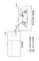
- FIG. 2 is an explanatory diagram for explaining restrictions on the reference relationship imposed on the tile in the existing method.
- a picture PIC0 that is a picture to be encoded (decoded) and a picture PIC1 that is a reference picture of the picture PIC0 are shown.
- Picture PIC0 is divided into a plurality of tiles including a tile T 04.
- the picture PIC1 is also divided into a plurality of tiles.
- intra prediction of the tile T 04 in the PU prediction unit
- it is prohibited to be used as reference pixels to pixels of other tiles in the picture PIC0 (arrow R A1, R A2). It is permissible to use a pixel in the same tile as a reference pixel (arrow R A3 ).
- the prediction mode constraint equivalent to the constraint imposed on the slice end PU is imposed.
- a tile usually has a shape that is closer to a square compared to a slice. Therefore, by using tiles instead of slices, a decrease in prediction accuracy due to prediction mode restrictions is mitigated.
- inter prediction it is allowed to use a pixel of any tile of the picture PIC1 as a reference pixel (arrow R B1 ).
- the HEVC method is an image encoding method suitable for compressing a high-resolution image with high encoding efficiency.
- not all terminals currently used and terminals used in the future have the ability to handle high-resolution images.
- an excessively high resolution is inconvenient for a terminal having a processor with low processing performance, a terminal receiving an image through a communication channel with a low bandwidth, or a terminal having a display with a low resolution. Therefore, it is beneficial to realize so-called partial decoding in order to provide a high-resolution image to a terminal with high capability and provide a low-resolution image to a terminal with relatively low capability.
- Tile division is suitable for partial decoding in that decoding processing is performed separately for each tile. Therefore, the technology according to the present disclosure provides a mechanism that enables partial decoding by utilizing the tile division described above.
- ROI region of interest
- non-ROI non-target area
- the ROI is usually an area of particular interest in the particular application of the image. For example, a person area detected in an image may be set as an ROI in the use of a surveillance camera video. Further, in a video conference application, a speaker's area detected in an image may be set as an ROI.
- tile division is determined according to the position of the ROI set in the image.
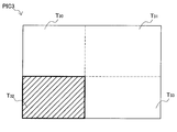
- a rectangular ROI shaded with diagonal lines is set at the center of the picture PIC2.
- a tile boundary is provided along the edge of the ROI.
- the picture PIC2 is divided into nine tiles T 20 to T 28 .
- Tile T 24 is an ROI tile.
- the tiles T 20 to T 23 and T 25 to T 28 are non-ROI tiles.
- a rectangular ROI shaded with diagonal lines is set so as to contact the lower left corner of the picture PIC3.
- a tile boundary is provided along the edge of the ROI.
- the picture PIC3 is divided into four tiles T 30 to T 33 .
- Tile T 32 is the ROI tile.
- Tiles T 30, T 31 and T 33 are non-ROI tile.
- FIG. 4 is an explanatory diagram for explaining the restriction of the reference relationship imposed on the tile in one embodiment.
- a picture PIC0 that is an encoding (decoding) target image and a picture PIC4 that is a reference image of the picture PIC0 are illustrated.
- Picture PIC0 is divided into a plurality of tiles including a tile T 04.
- Tile T 04 is a ROI tile of the picture PIC0.
- Picture PIC4 is divided into a plurality of tiles including a tile T 43.
- Tile T 43 is a ROI tile of the picture PIC4.
- the restriction of the reference relationship imposed on the non-ROI tile may be the same as the existing method described with reference to FIG. That is, in intra prediction for PUs in non-ROI tiles, use of pixels in other tiles as reference pixels is prohibited, and use of pixels in the same tile as reference pixels is allowed. In inter prediction for PUs in non-ROI tiles, it is allowed to use pixels of both ROI tiles and non-ROI tiles of the reference image as reference pixels.
- the decoder will not refer to any non-ROI tiles when decoding ROI tiles. As a result, it is possible to decode a series of partial images that display only ROI tiles from the encoded stream. Two embodiments of an encoder and a decoder that enable such partial decoding will be described in detail later.
- FIG. 5 is an explanatory diagram for explaining an example of a technique for setting an ROI tile in an image.
- a person is shown in the encoding target image PIC0.
- the person is recognized by applying a known person detection method such as a feature amount matching method, a background difference extraction method, and a skin color region extraction method to the encoding target image PIC0.
- a person region RG1 detected as a result of the person detection process is set as a region of interest (ROI).
- the tile division is determined according to the set ROI position. For example, the image may be divided so that the top, bottom, left and right edges of the rectangular ROI coincide with the tile boundary. The position of the tile boundaries may be adjusted so that the ROI tile size is equal across multiple images.
- the encoding target image PIC0 is divided into nine tiles so that the edge of the person region RG1 matches the tile boundary.
- ROI tiles The example in which one ROI tile is set for one image has been mainly described so far. However, the present invention is not limited to this example, and a plurality of ROI tiles may be set for one image.
- the picture PIC5 is divided into nine tiles T 50 to T 58 .
- Tile T 53 and T 55 are ROI tiles.
- the tiles T 50 to T 52, T 54 , and T 56 to T 58 are non-ROI tiles.
- two or more ROI tiles independent of each other may be set in one image.
- each ROI can be tracked across multiple images.
- intra prediction for PUs in ROI tiles it may be prohibited to use pixels of other ROI tiles in the same picture as reference pixels.
- inter prediction for PUs in a ROI tile it is allowed to use pixels of the corresponding ROI tile of the reference image as reference pixels, and pixels of other ROI tiles and non-ROI tiles of the reference image are used as reference pixels. Can be banned.
- the picture PIC6 is divided into 15 tiles including ROI tiles T 60 to T 65 .
- ROI tile T 64 is a first level ROI tile.
- ROI tiles T 60 to T 63 and T 65 are second level ROI tiles.
- the first level ROI tile corresponds to the region of most interest in the particular application of the image.
- the second level ROI tile corresponds to a larger area surrounding the first level ROI.
- ROI tiles corresponding to a plurality of levels of ROIs having different sizes may be set in one image.
- the first level ROI may be a face area of a person
- the second level ROI may be an area of the entire body of the person.
- it is allowed to use the same or higher level ROI tile pixels of the reference image as reference pixels, and lower ROI tile and non-ROI tile pixels as reference pixels. Use may be prohibited.
- FIG. 7 is a block diagram illustrating an example of the configuration of the image encoding device 1 according to the first embodiment.
- the image encoding device 1 includes a rearrangement buffer 11, a tile division unit 12, a subtraction unit 13, an orthogonal transformation unit 14, a quantization unit 15, a lossless encoding unit 16, a storage buffer 17, and a rate control unit.
- an inverse quantization unit 21 an inverse orthogonal transform unit 22, an addition unit 23, a deblock filter 24, a frame memory 25, selectors 26 and 27, an intra prediction unit 30, an inter prediction unit 35, and a prediction control unit 40.
- a series of original image data in digital format is input to the rearrangement buffer 11.
- Each image included in the original image data is an encoding target image.
- the rearrangement buffer 11 rearranges the images included in the original image data in the encoding / decoding order according to the GOP (Group of Pictures) structure. Then, the rearrangement buffer 11 outputs the original image data in which the encoding target images are arranged in the order after the rearrangement to the subtraction unit 13, the intra prediction unit 30, and the inter prediction unit 35.
- the tile dividing unit 12 divides the encoding target image input to the rearrangement buffer 11 into a plurality of tiles including a region of interest (ROI) tile.
- the tile dividing unit 12 can set an ROI for each image, and can determine tile division according to the position of the set ROI.
- the tile dividing unit 12 may set any ROI in the image according to the use of the image.
- the tile division unit 12 may perform person detection for each image and set the detected person region as the ROI.
- the tile dividing unit 12 generates a tile parameter indicating how each image is divided and which tile is a ROI tile. Then, the tile dividing unit 12 outputs the generated tile parameter to the lossless encoding unit 16, the intra prediction unit 30, the inter prediction unit 35, and the prediction control unit 40.
- An example of a more detailed configuration of the tile dividing unit 12 will be further described later.
- the subtraction unit 13 is supplied with original image data input from the rearrangement buffer 11 and predicted image data described later.
- the subtraction unit 13 calculates prediction error data that is the difference between the original image data and the predicted image data, and outputs the calculated prediction error data to the orthogonal transform unit 14.
- the orthogonal transform unit 14 performs orthogonal transform on the prediction error data input from the subtraction unit 13.
- the orthogonal transformation performed by the orthogonal transformation part 14 may be discrete cosine transformation (Discrete Cosine Transform: DCT) or Karoonen-Labe transformation, for example.
- the orthogonal transform unit 14 outputs transform coefficient data acquired by the orthogonal transform process to the quantization unit 15.
- the quantization unit 15 is supplied with transform coefficient data input from the orthogonal transform unit 14 and a rate control signal from the rate control unit 18 described later.
- the quantizing unit 15 quantizes the transform coefficient data and outputs the quantized transform coefficient data (hereinafter referred to as quantized data) to the lossless encoding unit 16 and the inverse quantization unit 21.
- the quantization unit 15 changes the bit rate of the quantized data input to the lossless encoding unit 16 by switching the quantization parameter (quantization scale) based on the rate control signal from the rate control unit 18.
- the lossless encoding unit 16 is supplied with quantized data input from the quantization unit 15 and various parameters to be inserted into the header area of the encoded stream.
- the parameters supplied to the lossless encoding unit 16 include tile parameters generated by the tile dividing unit 12, information regarding intra prediction generated by the intra prediction unit 30, and information regarding inter prediction generated by the inter prediction unit 35. obtain.
- the lossless encoding unit 16 generates an encoded stream by performing a lossless encoding process on the quantized data for each tile.
- the lossless encoding by the lossless encoding unit 16 may be variable length encoding or arithmetic encoding, for example. Further, the lossless encoding unit 16 inserts various parameters including tile parameters into the header area of the encoded stream. Then, the lossless encoding unit 16 outputs the generated encoded stream to the accumulation buffer 17.
- the accumulation buffer 17 temporarily accumulates the encoded stream input from the lossless encoding unit 16 using a storage medium such as a semiconductor memory.
- the accumulation buffer 17 outputs the accumulated encoded stream at a rate corresponding to the bandwidth of the transmission path (or the output line from the image encoding device 1).
- the rate control unit 18 monitors the free capacity of the accumulation buffer 17. Then, the rate control unit 18 generates a rate control signal according to the free capacity of the accumulation buffer 17 and outputs the generated rate control signal to the quantization unit 15. For example, the rate control unit 18 generates a rate control signal for reducing the bit rate of the quantized data when the free capacity of the storage buffer 17 is small. For example, when the free capacity of the accumulation buffer 17 is sufficiently large, the rate control unit 18 generates a rate control signal for increasing the bit rate of the quantized data.
- the inverse quantization unit 21 performs an inverse quantization process on the quantized data input from the quantization unit 15. Then, the inverse quantization unit 21 outputs transform coefficient data acquired by the inverse quantization process to the inverse orthogonal transform unit 22.
- the inverse orthogonal transform unit 22 restores the prediction error data by performing an inverse orthogonal transform process on the transform coefficient data input from the inverse quantization unit 21. Then, the inverse orthogonal transform unit 22 outputs the restored prediction error data to the addition unit 23.
- the adding unit 23 generates decoded image data (also referred to as reconstructed image data) by adding the restored prediction error data input from the inverse orthogonal transform unit 22 and the predicted image data input from the selector 27. To do. Then, the addition unit 23 outputs the generated decoded image data to the deblock filter 24 and the frame memory 25.
- decoded image data also referred to as reconstructed image data
- the deblocking filter 24 performs a filtering process for reducing block distortion that occurs during image encoding. Then, the deblocking filter 24 outputs the decoded image data after filtering from which block distortion has been removed to the frame memory 25.
- the frame memory 25 stores the decoded image data input from the adder 23 and the decoded image data after filtering input from the deblock filter 24 using a storage medium.
- the selector 26 reads out the decoded image data before filtering used for intra prediction from the frame memory 25 and supplies the read decoded image data to the intra prediction unit 30 as reference image data.
- the selector 26 reads out the decoded image data after filtering used for inter prediction from the frame memory 25 and supplies the read out decoded image data to the inter prediction unit 35 as reference image data.
- the selector 27 switches between the intra prediction mode and the inter prediction mode.
- the selector 27 In the intra prediction mode, the selector 27 outputs the prediction image data input from the intra prediction unit 30 to the subtraction unit 13 and the addition unit 23 and outputs information related to intra prediction to the lossless encoding unit 16.
- the selector 27 outputs the prediction image data input from the inter prediction unit 35 to the subtraction unit 13 and the addition unit 23 and outputs information related to the inter prediction to the lossless encoding unit 16.
- the selector 27 may switch between the intra prediction mode and the inter prediction mode according to the size of the cost function value.
- the intra prediction unit 30 performs an intra prediction process based on the original image data input from the rearrangement buffer 11 and the decoded image data supplied via the selector 26. For example, the intra prediction unit 30 evaluates the prediction results in a plurality of prediction modes using a predetermined cost function, and selects the prediction mode with the minimum cost function value as the optimal prediction mode. The intra prediction unit 30 generates information related to intra prediction including prediction mode information indicating the selected optimal prediction mode. Then, the intra prediction unit 30 outputs information related to intra prediction, predicted image data, and a cost function value to the selector 27.
- the inter prediction unit 35 performs an inter prediction process based on the original image data input from the rearrangement buffer 11 and the decoded image data supplied via the selector 26. For example, the inter prediction unit 35 evaluates the prediction results in a plurality of prediction modes using a predetermined cost function, and selects the prediction mode that minimizes the cost function value as the optimal prediction mode. The inter prediction unit 35 generates information regarding inter prediction including prediction mode information indicating the selected optimal prediction mode, motion vector information, and reference image information. Then, the inter prediction unit 35 outputs information on inter prediction, predicted image data, and a cost function value to the selector 27.
- the prediction control unit 40 controls restrictions on reference relationships imposed on intra prediction and inter prediction. For example, when the intra prediction is executed for each PU, the prediction control unit 40 controls the intra prediction unit 30 so that a tile different from the tile to which the PU belongs is not referred to. When the reference image does not include the ROI tile, the prediction control unit 40 does not cause the inter prediction unit 35 to perform inter prediction for the PU in the ROI tile of the encoding target image.
- the prediction control unit 40 controls the inter prediction unit 35 so that the non-ROI tile of the reference image is not referred to.
- the prediction control unit 40 inter-predicts any tile of the reference image regardless of whether each tile of the reference image is a ROI tile. Reference may be made to part 35.
- the inter prediction unit 35 may offset the motion vector information depending on the position of the ROI tile of the reference image when performing the inter prediction on the PU in the ROI tile.
- the offset amount here may correspond to, for example, a difference between the position of the upper left corner of the ROI tile of the encoding target image and the position of the upper left corner of the ROI tile of the reference image.
- FIG. 8 is a block diagram illustrating an example of a detailed configuration of the tile dividing unit 12.
- the tile division unit 12 includes an ROI size setting unit 122, a person detection unit 124, and a tile parameter generation unit 126.
- the ROI size setting unit 122 sets the tile size of the ROI tile based on, for example, user input or system settings stored in advance.
- the person detection unit 124 performs person detection by applying a known person detection method to the encoding target image. Then, the person detection unit 124 sets a region of interest (ROI) including the detected person region as an encoding target image.
- the tile parameter generation unit 126 determines tile division according to the position of the ROI set by the person detection unit 124, and generates tile parameters for specifying the determined tile division and ROI tile. Then, the tile parameter generation unit 126 outputs the generated tile parameters to the lossless encoding unit 16, the intra prediction unit 30, the inter prediction unit 35, and the prediction control unit 40.
- Table 1 shows an example of tile parameters that can be generated by the tile parameter generation unit 126.
- the first column of Table 1 shows the parameter name (Parameter Name).
- the second column shows the location where each parameter can be inserted.
- the parameter indicating “Yes” in the third column is a parameter newly defined in the technology according to the present disclosure.
- Parameter “num_tile_columns_minus1” represents the number of tile columns. If this parameter is zero, the number of tile columns is one.
- the parameter “num_tile_rows_minus1” represents the number of tile rows. If this parameter is zero, the number of tile rows is one.
- the parameter “uniform_spacing_flag” is a flag indicating whether or not the tile size is uniform in the image.
- the parameter “column_width [i]” represents the width of the i-th tile column.
- the parameter “row_height [i]” represents the height of the i-th tile row.
- Parameters “roi_tile_present_flag”, “coord_roi_tile_hor_minus1”, “coord_roi_tile_ver_minus1”, and “roi_tile_indicator [i]” are newly defined parameters.
- the parameter “roi_tile_present_flag” is a flag indicating whether the ROI tile is included in the encoding target image. When a plurality of ROI tiles can be set for one image, a parameter indicating the number of ROI tiles to be set may be generated instead of the flag.
- the parameters “coord_roi_tile_hor_minus1” and “coord_roi_tile_ver_minus1” indicate the position of the ROI tile (how many rows and how many columns are ROI tiles). For example, if these two parameters are both zero, the tile in the first row and first column is the ROI tile. When the parameter “roi_tile_present_flag” indicates False (no ROI tile), the parameters “coord_roi_tile_hor_minus1” and “coord_roi_tile_ver_minus1” may be omitted.
- the parameters “roi_tile_present_flag”, “coord_roi_tile_hor_minus1”, and “coord_roi_tile_ver_minus1” may be inserted into the SPS or PPS. Instead, these parameters may be inserted into SEI (Supplemental Enhancement Information).
- the parameter “roi_tile_indicator [i]” is a parameter that can be inserted into the slice header. This parameter is a flag indicating whether or not the i-th tile in each slice is an ROI tile.
- tile parameters described here are only examples. Some of the parameters described above may be omitted or additional parameters may be generated. Further, other parameters having different names or types may be generated instead of the parameters described above. In addition, when the tile parameter frequently changes for each picture, the tile parameter may be stored not in SPS or PPS but in APS (Adaptation Parameter Set).
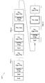
- FIG. 9 is an explanatory diagram for describing an example of a configuration of an encoded stream that can be generated in the present embodiment.
- an encoded stream ST1 is shown as an example.
- the encoded stream ST1 includes image data of a plurality of pictures PIC11, PIC12, PIC13,.
- the picture PIC11 is a picture that does not include an ROI tile.
- the pictures PIC12 and PIC13 are pictures including ROI tiles.
- parameters indicating the position of the ROI tile for example, “coord_roi_tile_hor_minus1” and “coord_roi_tile_ver_minus1”.
- the lossless encoding unit 16 generates one encoded stream including both ROI tile image data and non-ROI tile image data.
- non-ROI tile image data is ignored, and only ROI tiles can be decoded from ROI tile image data.
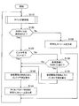
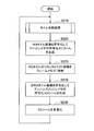
- FIG. 10 is a flowchart illustrating an example of a processing flow during encoding according to the present embodiment. The process shown in FIG. 10 is repeated for each encoding target image. For the sake of simplicity of explanation, portions that are not particularly different from the processing according to the existing method are omitted from the drawing.
- the tile dividing unit 12 executes a tile dividing process (step S110).
- the encoding target image can be divided into a plurality of tiles including the ROI tile.
- the detailed flow of the tile division process will be further described later.
- the prediction control unit 40 determines whether or not an ROI tile has been set for the encoding target image (step S120).
- the process proceeds to step S125.
- the process proceeds to step S150.
- step S125 the prediction control unit 40 determines whether the encoding target image is an intra prediction frame (step S125). For example, when the encoding target image is an I picture, the encoding target image is an intra prediction frame. In this case, inter prediction is not executed, and the process proceeds to step S140. On the other hand, when the encoding target image is not an intra prediction frame, the process proceeds to step S130.
- step S130 the prediction control unit 40 determines whether or not a ROI tile is included in the reference image (step S130). If the reference image includes the ROI tile, the process proceeds to step S135. When the ROI tile is not included in the reference image, the process proceeds to step S140.
- step S135 the inter prediction unit 35 performs inter prediction (step S135).
- the prediction control unit 40 controls the inter prediction unit 35 so that the non-ROI tile of the reference image is not referred to during the inter prediction for the PU in the ROI tile.
- the prediction control unit 40 allows the inter prediction unit 35 to refer to an arbitrary tile of the reference image when inter prediction is performed on a PU in a non-ROI tile.
- step S140 the intra prediction unit 30 performs intra prediction (step S140).
- the prediction control unit 40 controls the intra prediction unit 30 so that, when intra prediction is executed for each PU, a tile different from the tile to which the PU belongs is not referred to.
- step S145 the lossless encoding unit 16 encodes the quantized data for each tile to generate an encoded stream.
- the lossless encoding unit 16 inserts various parameters that may include tile parameters, information related to intra prediction, and information related to inter prediction, into the header area of the encoded stream (step S145).
- step S150 since the ROI tile is not set in the encoding target image, the image encoding device 1 generates an encoded stream as in the existing method (step S150). A tile parameter indicating that the encoding target image does not include the ROI tile is inserted into the header area of the encoded stream.
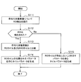
- FIG. 11 is a flowchart showing an example of a detailed flow of tile division processing.
- the tile dividing unit 12 performs ROI detection (for example, person detection) on the encoding target image (step S111).
- the tile division unit 12 determines whether or not an ROI is detected as a result of ROI detection (step S112).
- the tile dividing unit 12 divides the encoding target image into a plurality of tiles including the ROI tile and the non-ROI tile (step S113).
- the tile dividing unit 12 generates a tile parameter including a parameter indicating the position of the ROI tile (Step S114).
- the tile dividing unit 12 generates a tile parameter including a parameter indicating that the ROI tile does not exist (that is, the encoding target image does not include the ROI tile) ( Step S115).
- the tile dividing unit 12 may set a provisional ROI tile as an encoding target image when no person region or other ROI is detected.
- the tile dividing unit 12 may set a temporary ROI tile at a predetermined position (such as the center of the image) or the same position as the last set ROI tile. Thereby, at least one ROI tile can be included in every image.
- a decoder that partially decodes only ROI tiles, it is possible to eliminate the time during which ROI tiles are missing.
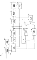
- FIG. 12 is a block diagram illustrating an example of the configuration of the image decoding device 6 according to the present embodiment.
- the image decoding device 6 includes a stream acquisition unit 61, a tile identification unit 62, a lossless decoding unit 63, an inverse quantization unit 64, an inverse orthogonal transform unit 65, an addition unit 66, a deblock filter 67, a rearrangement filter A buffer 68, a resolution adjustment unit 69, a frame memory 70, selectors 71 and 72, an intra prediction unit 80, an inter prediction unit 85, and a determination unit 90 are provided.
- the stream acquisition unit 61 acquires an encoded stream input via a transmission path, and buffers the encoded stream using a storage medium. Further, the stream acquisition unit 61 parses the encoded stream and acquires the tile parameter inserted in the header area.
- the tile parameter acquired here may include a parameter indicating whether each decoding target image includes an ROI tile. When the decoding target image includes the ROI tile, the tile parameter also includes a parameter indicating which tile is the ROI.
- the stream acquisition unit 61 may acquire these tile parameters from the SPS, PPS, or slice header of the encoded stream. Instead, the stream acquisition unit 61 may acquire tile parameters from the SEI of the encoded stream.
- the tile identification unit 62 acquires the tile parameter described above from the stream acquisition unit 61. Then, the tile identifying unit 62 identifies the tile division of each decoding target image and the position of the ROI tile based on the acquired tile parameter.
- the tile division can be identified in the same manner as the existing method based on the parameters “num_tile_columns_minus1”, “num_tile_rows_minus1”, “uniform_spacing_flag”, “column_width [i]”, and “row_height [i]” illustrated in Table 1, for example. .
- a newly defined parameter “roi_tile_present_flag” indicates whether or not an ROI tile exists.
- the position of the ROI tile can be identified based on the newly defined parameters “coord_roi_tile_hor_minus1” and “coord_roi_tile_ver_minus1”, or “roi_tile_indicator [i]”.
- the lossless decoding unit 63 decodes the encoded stream buffered by the stream acquisition unit 61. More specifically, the lossless decoding unit 63 decodes the image data of the ROI tile identified based on the tile parameter described above. The lossless decoding unit 63 also decodes the image data of the non-ROI tile when the determination unit 90 instructs the entire decoding. When the determination unit 90 instructs partial decoding, the lossless decoding unit 63 does not decode image data of non-ROI tiles. The lossless decoding unit 63 outputs the decoded image data (quantized data) to the inverse quantization unit 64. Further, the lossless decoding unit 63 outputs information related to intra prediction to the intra prediction unit 80. In addition, the lossless decoding unit 63 outputs information related to inter prediction to the inter prediction unit 85.
- the inverse quantization unit 64 inversely quantizes the quantized data decoded by the lossless decoding unit 63.
- the inverse orthogonal transform unit 65 generates prediction error data by performing inverse orthogonal transform on the transform coefficient data input from the inverse quantization unit 64 according to the orthogonal transform method used at the time of encoding. Then, the inverse orthogonal transform unit 65 outputs the generated prediction error data to the addition unit 66.
- the adding unit 66 generates decoded image data (reconstructed image data) by adding the prediction error data input from the inverse orthogonal transform unit 65 and the predicted image data input from the selector 72. Then, the adding unit 66 outputs the generated decoded image data to the deblock filter 67 and the frame memory 70.
- the deblock filter 67 performs a filtering process for removing block distortion appearing in the decoded image. Then, the deblock filter 67 outputs the decoded image data after filtering from which block distortion has been removed to the rearrangement buffer 68 and the frame memory 70.
- the rearrangement buffer 68 rearranges the images input from the deblock filter 67 in the decoding order, in the display order. Then, the rearrangement buffer 68 outputs a series of decoded image data after the rearrangement to the resolution adjustment unit 69.
- the resolution adjustment unit 69 adjusts the resolution of each decoded image input from the rearrangement buffer 68.
- the resolution adjustment unit 69 may generate the display image by increasing the resolution of the decoded image of the ROI tile generated by the partial decoding in accordance with the resolution of the display.
- the resolution adjustment unit 69 may generate a display image by reducing the resolution of a decoded image (including ROI tiles and non-ROI tiles) generated by overall decoding.
- the resolution adjustment unit 69 outputs the decoded image data with the adjusted resolution to, for example, a display (not shown) connected to the image decoding device 6.
- the frame memory 70 stores the decoded image data before filtering input from the adder 66 and the decoded image data after filtering input from the deblock filter 67 using a storage medium.
- the selector 71 switches the output destination of data from the frame memory 70 between the intra prediction unit 80 and the inter prediction unit 85 according to the mode information decoded by the lossless decoding unit 63. For example, when the intra prediction mode is designated, the selector 71 outputs the decoded image data before filtering supplied from the frame memory 70 to the intra prediction unit 80 as reference image data. Further, when the inter prediction mode is designated, the selector 71 outputs the decoded image data after filtering supplied from the frame memory 70 to the inter prediction unit 85 as reference image data.
- the selector 72 switches the output source of the predicted image data to be supplied to the adding unit 66 between the intra prediction unit 80 and the inter prediction unit 85 according to the mode information decoded by the lossless decoding unit 63. For example, the selector 72 supplies the prediction image data output from the intra prediction unit 80 to the adding unit 66 when the intra prediction mode is designated. The selector 72 supplies the prediction image data output from the inter prediction unit 85 to the addition unit 66 when the inter prediction mode is designated.
- the intra prediction unit 80 executes intra prediction based on the information related to intra prediction input from the lossless decoding unit 63 and the reference image data from the frame memory 70, and generates predicted image data. Then, the intra prediction unit 80 outputs the generated predicted image data to the selector 72.
- the inter prediction unit 85 performs inter prediction based on information related to inter prediction input from the lossless decoding unit 63 and reference image data from the frame memory 70, and generates predicted image data. Then, the inter prediction unit 85 outputs the generated predicted image data to the selector 72.
- Information related to inter prediction typically includes prediction mode information, motion vector information, and reference image information.
- the inter prediction unit 85 when the motion vector information acquired for the PU in the ROI tile of the decoding target image is offset depending on the position of the ROI tile on the encoder side, the inter prediction unit 85 The offset of the motion vector information can be canceled according to the difference in the position of the ROI tile between the two. Then, the inter prediction unit 85 may perform inter prediction using the motion vector information from which the offset is canceled.
- the determination unit 90 determines whether the image decoding device 6 should perform partial decoding or total decoding. For example, the determination unit 90 may determine that partial decoding should be performed when the performance of the processor, the memory, or the display is not sufficient to decode the entire decoding target image. The determination unit 90 may determine that partial decoding should be performed when the bandwidth of a communication channel with a device that transmits an encoded stream is narrow. In this case, the determination unit 90 may request the device that transmits the encoded stream to transmit only the ROI tile image data. In addition, the determination unit 90 determines that partial decoding should be performed when partial decoding is designated by the user (for example, because the user does not need to view a non-ROI tile image). May be.
- the determination unit 90 instructs the lossless decoding unit 63 to perform partial decoding. If the determination unit 90 determines that the entire decoding should be performed, the determination unit 90 instructs the lossless decoding unit 63 to perform the entire decoding.
- the lossless decoding unit 63 decodes only the ROI tile of the decoding target image. On the other hand, when the entire decoding is instructed, the lossless decoding unit 63 decodes the non-ROI tile in addition to the ROI tile.
- the resolution adjustment unit 69 adjusts the resolution of the ROI tile image based on the size of the ROI tile and the size of the display. On the other hand, when the entire decoding is instructed by the determination unit 90, the resolution adjustment unit 69 adjusts the resolution of the decoded image based on the size of the entire decoded image and the display size.
- FIG. 13 is a flowchart illustrating an example of a processing flow at the time of decoding according to the present embodiment. The process shown in FIG. 13 is repeated for each decoding target image. For the sake of simplicity of explanation, portions that are not particularly different from the processing according to the existing method are omitted from the drawing.
- the stream acquisition unit 61 acquires tile parameters from the encoded stream (step S160).
- the tile identification unit 62 determines whether or not the decoding target image is divided into tiles (step S165). If the decoding target image is tile-divided, the process proceeds to step S170. On the other hand, if the decoding target image is not divided into tiles, the process proceeds to step S190.
- step S170 the tile identifying unit 62 identifies the tile division of the decoding target image and the position of the ROI tile based on the tile parameter (step S170).
- step S175 determines whether or not partial decoding should be executed. If it is determined that partial decoding should be performed, the process proceeds to step S180. On the other hand, if it is determined that partial decoding should not be executed, the process proceeds to step S195.
- step S180 the lossless decoding unit 63 extracts only ROI tile image data from all tiles from the buffered encoded stream (step S180), and decodes the extracted ROI tile image data (step S180). Step S185).
- step S190 the lossless decoding unit 63 decodes the ROI tile and non-ROI tile image data of the buffered encoded stream (step S190).
- the resolution adjustment unit 69 adjusts the resolution of the decoded image input from the rearrangement buffer 68 according to the resolution of the display (step S195). Then, the image with the adjusted resolution is displayed on the display.
- Scalable encoding (also referred to as SVC (Scalable Video Coding) generally refers to a technique for hierarchically encoding a layer that transmits a coarse image signal and a layer that transmits a fine image signal.
- SVC Scalable Video Coding
- the scalable coding realized in the technology according to the present disclosure can be expressed as regional scalability, unlike the above-described existing scalability.
- the base layer encoded stream includes image data of only ROI tiles.
- the ROI tile image data is omitted in the enhancement layer encoded stream.
- the enhancement layer encoded stream includes image data of only non-ROI tiles.
- a decoder that performs partial decoding decodes a base layer encoded stream to generate decoded image data including only ROI tiles.
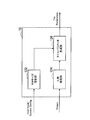
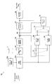
- FIG. 14 is a block diagram illustrating an example of a schematic configuration of the image encoding device 10 according to the present embodiment.
- the image encoding device 10 includes a rearrangement buffer 11, a tile division unit 12, a first encoding unit 1 a, a second encoding unit 1 b, a common memory 2, and a multiplexing unit 3.
- the rearrangement buffer 11 rearranges the encoding target images included in the series of original image data in the encoding / decoding order according to the GOP structure.
- the tile dividing unit 12 divides the encoding target image into a plurality of tiles including the ROI tile. Then, the tile dividing unit 12 generates a tile parameter indicating how each image is divided and which tile is the ROI tile.
- the tile dividing unit 12 outputs a partial image corresponding to the ROI tile in the encoding target image (hereinafter referred to as ROI tile image) and tile parameters to the first encoding unit 1a. Further, the tile dividing unit 12 outputs a partial image corresponding to a non-ROI tile (hereinafter referred to as a non-ROI tile image) to the second encoding unit 1b.
- the tile parameters can be stored by the common memory 2.
- the first encoding unit 1a encodes the ROI tile image to generate a base layer encoded stream.
- the second encoding unit 1b encodes the non-ROI tile image and generates an enhancement layer encoded stream.
- the common memory 2 stores information commonly used between layers.
- the multiplexing unit 3 multiplexes the base layer encoded stream generated by the first encoding unit 1a and the enhancement layer encoded stream generated by the second encoding unit 1b, and multi-layer multiplexing Create a stream.
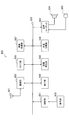
- FIG. 15 is a block diagram showing an example of the configuration of the first coding unit 1a shown in FIG.
- the first encoding unit 1a includes a subtraction unit 13, an orthogonal transformation unit 14, a quantization unit 15, a lossless encoding unit 16a, a storage buffer 17, a rate control unit 18, an inverse quantization unit 21, and an inverse unit.
- An orthogonal transformation unit 22, an addition unit 23, a deblock filter 24, a frame memory 25, selectors 26 and 27, an intra prediction unit 30a, an inter prediction unit 35a, and a prediction control unit 40a are provided.
- the subtraction unit 13 is supplied with the original image data and predicted image data of the ROI tile image input from the tile dividing unit 12 shown in FIG.
- the subtraction unit 13 calculates prediction error data that is a difference between the original image data and the predicted image data.
- the orthogonal transform unit 14 performs orthogonal transform on the prediction error data input from the subtraction unit 13.
- the quantization unit 15 quantizes the transform coefficient data input from the orthogonal transform unit 14 and generates quantized data.
- the lossless encoding unit 16a generates a base layer encoded stream by performing a lossless encoding process on the quantized data of the ROI tile. Also, the lossless encoding unit 16a inserts various parameters including tile parameters into the header area of the base layer encoded stream.
- the accumulation buffer 17 temporarily accumulates the base layer encoded stream generated by the lossless encoding unit 16a, and outputs the accumulated encoded stream to the multiplexing unit 3 illustrated in FIG.
- the rate control unit 18 monitors the free capacity of the storage buffer 17 and controls the bit rate of the quantized data.
- the inverse quantization unit 21 performs an inverse quantization process on the quantized data input from the quantization unit 15.
- the inverse orthogonal transform unit 22 restores the prediction error data by performing an inverse orthogonal transform process on the transform coefficient data input from the inverse quantization unit 21.
- the adder 23 adds the prediction error data input from the inverse orthogonal transform unit 22 and the predicted image data input from the selector 27 to generate decoded image data.
- the deblocking filter 24 performs a filtering process for reducing block distortion that occurs when an image is encoded.
- the frame memory 25 stores decoded image data before filtering and decoded image data after filtering.
- the intra prediction unit 30 a performs an intra prediction process on the ROI tile image based on the original image data of the ROI tile image input from the tile dividing unit 12 and the decoded image data supplied via the selector 26.
- the inter prediction unit 35 a performs inter prediction processing on the ROI tile image based on the original image data of the ROI tile image input from the tile dividing unit 12 and the decoded image data supplied via the selector 26.
- the prediction control unit 40a controls restrictions on reference relationships imposed on intra prediction and inter prediction. For example, the prediction control unit 40a controls the intra prediction unit 30a so that other tiles are not referred to when intra prediction is executed for each PU in the ROI tile. When the reference image does not include the ROI tile, the prediction control unit 40a does not cause the inter prediction unit 35a to perform inter prediction. In addition, for example, when the inter prediction is executed for each PU in the ROI tile, the prediction control unit 40a controls the inter prediction unit 35a so that only the ROI tile of the reference image is referred to.
- FIG. 16 is a block diagram illustrating an example of the configuration of the second encoding unit 1b illustrated in FIG.
- the second encoding unit 1b includes a subtraction unit 13, an orthogonal transformation unit 14, a quantization unit 15, a lossless encoding unit 16b, an accumulation buffer 17, a rate control unit 18, an inverse quantization unit 21, and an inverse unit.
- An orthogonal transform unit 22, an adder unit 23, a deblock filter 24, a frame memory 25, selectors 26 and 27, an intra prediction unit 30b, an inter prediction unit 35b, and a prediction control unit 40b are provided.
- the subtraction unit 13 is supplied with the original image data and the predicted image data of the non-ROI tile image input from the tile dividing unit 12 shown in FIG.
- the subtraction unit 13 calculates prediction error data that is a difference between the original image data and the predicted image data.
- the orthogonal transform unit 14 performs orthogonal transform on the prediction error data input from the subtraction unit 13.
- the quantization unit 15 quantizes the transform coefficient data input from the orthogonal transform unit 14 and generates quantized data.
- the lossless encoding unit 16b generates an enhancement layer encoded stream by performing a lossless encoding process on the non-ROI tile quantization data. Since the tile parameter can be reused between layers, the lossless encoding unit 16b does not have to insert the tile parameter in the header region of the enhancement layer encoded stream.
- the accumulation buffer 17 temporarily accumulates the enhancement layer coded stream generated by the lossless coding unit 16b, and outputs the accumulated coded stream to the multiplexing unit 3 shown in FIG.
- the rate control unit 18 monitors the free capacity of the storage buffer 17 and controls the bit rate of the quantized data.
- the inverse quantization unit 21 performs an inverse quantization process on the quantized data input from the quantization unit 15.
- the inverse orthogonal transform unit 22 restores the prediction error data by performing an inverse orthogonal transform process on the transform coefficient data input from the inverse quantization unit 21.
- the adder 23 adds the prediction error data input from the inverse orthogonal transform unit 22 and the predicted image data input from the selector 27 to generate decoded image data.
- the deblocking filter 24 performs a filtering process for reducing block distortion that occurs when an image is encoded.
- the frame memory 25 stores the entire decoded image data (before and after filtering) including both ROI tiles and non-ROI tiles.
- the intra prediction unit 30 b performs an intra prediction process on the non-ROI tile image based on the original image data of the non-ROI tile image input from the tile dividing unit 12 and the decoded image data supplied via the selector 26.
- the inter prediction unit 35 b performs an inter prediction process for the non-ROI tile image based on the original image data of the non-ROI tile image input from the tile dividing unit 12 and the decoded image data supplied via the selector 26. .
- the prediction control unit 40b controls the intra prediction unit 30b so that other tiles are not referred to when intra prediction is executed for each PU in the non-ROI tile.
- the prediction control unit 40b selects any tile of the reference image regardless of whether each tile of the reference image is a ROI tile. You may refer to
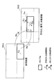
- FIG. 17 is an explanatory diagram for describing an example of a configuration of a multiplexed stream that can be generated in the present embodiment.
- an example multiplexed stream ST2 is shown.
- the multiplexed stream ST2 includes a base layer encoded stream and an enhancement layer encoded stream.
- the encoded stream of the base layer includes image data of only ROI tiles in addition to header data such as SPS, PPS, and slice header.
- the enhancement layer encoded stream includes image data of only non-ROI tiles.
- the image data of the ROI tile of the picture PIC21 is included in the encoded stream of the base layer, and the image data of one or more non-ROI tiles of the picture PIC21 is included in the encoded stream of the enhancement layer.
- the decoder performs partial decoding, only the base layer encoded stream is decoded.
- both the base layer encoded stream and the enhancement layer encoded stream are decoded, and the separately generated ROI tile image and non-ROI tile image are combined. .
- FIG. 18 is a flowchart illustrating an example of the flow of processing during encoding according to the present embodiment. The process shown in FIG. 18 is repeated for each encoding target image.
- the tile dividing unit 12 executes the tile dividing process described with reference to FIG. 11 (step S210).
- the tile division process the encoding target image is divided into an ROI tile image and a non-ROI tile image.
- the encoding target image is divided into an ROI tile image and a non-ROI tile image.
- the first encoding unit 1a encodes the ROI tile image to generate a base layer encoded stream (step S220).
- the reconstructed image of the ROI tile is stored in the frame memory 25 (step S225).
- the second encoding unit 1b encodes the non-ROI tile image to generate an enhancement layer encoded stream (step S230).
- the multiplexing unit 3 multiplexes the base layer encoded stream generated by the first encoding unit 1a and the enhancement layer encoded stream generated by the second encoding unit 1b, Multiplexed streams are generated (step S235).
- the first encoding unit 1a does not necessarily recognize that the image encoded by itself is an ROI tile image corresponding to a part of the original image. Also good. That is, the first encoding unit 1a can handle the ROI tile image as a single encoding target image that is not tile-divided. This means that the first encoding unit 1a can execute base layer encoding processing according to an image encoding scheme other than the HEVC scheme. For example, the first encoding unit 1a may generate a base layer encoded stream according to an image encoding method such as an AVC (Advanced Video Coding) method or an MPEG2 method that does not support tile division.
- the second encoding unit 1b recognizes the position of each tile in accordance with the HEVC scheme that supports tile division, and generates an enhancement layer encoded stream from which ROI tile image data is omitted.
- FIG. 19 is a block diagram illustrating an example of a schematic configuration of the image decoding device 60 according to the present embodiment.
- the image decoding device 60 includes a demultiplexing unit 5, a first decoding unit 6 a, a second decoding unit 6 b, a common memory 7, a synthesis unit 8, a resolution adjustment unit 9, and a determination unit 90.
- the demultiplexing unit 5 demultiplexes the multi-layer multiplexed stream into the base layer encoded stream and the enhancement layer encoded stream.
- the first decoding unit 6a decodes the ROI tile image from the base layer encoded stream.
- the second decoding unit 6b decodes the non-ROI tile image from the enhancement layer encoded stream when the entire decoding is instructed by the determination unit 90.
- the common memory 7 stores information commonly used between layers.
- the synthesizer 8 synthesizes the ROI tile image generated by the first decoder 6a and the non-ROI tile image generated by the second decoder 6b when the entire decoder is instructed by the determination unit 90. Restore the entire original image.
- the resolution adjusting unit 9 adjusts the resolution of the decoded image of the ROI tile generated by the first decoding unit 6a or the decoded image as a whole including the ROI tile and the non-ROI tile generated by the synthesizing unit 8.
- the resolution adjustment unit 9 outputs the decoded image data with the adjusted resolution to, for example, a display (not shown) connected to the image decoding device 60.
- the determination unit 90 determines whether the image decoding device 60 should perform partial decoding or total decoding according to, for example, the performance or type of the device, the communication bandwidth, or the designation by the user. If the determination unit 90 determines that partial decoding should be performed, the determination unit 90 causes the first decoding unit 6a to decode only the ROI tile image. On the other hand, if the determination unit 90 determines that the entire decoding should be performed, the determination unit 90 further causes the second decoding unit 6b to decode the non-ROI tile image from the enhancement layer encoded stream, and causes the combining unit 8 to detect the non-ROI tile image and the non-ROI tile image. The ROI tile image is combined.
- the first decoding unit 6a may decode the ROI image from the encoded stream of the base layer according to an image encoding method such as an AVC method or an MPEG2 method that does not support tile division.
- FIG. 20 is a block diagram showing an example of the configuration of the first decoding unit 6a shown in FIG.
- the first decoding unit 6a includes a lossless decoding unit 63a, an inverse quantization unit 64, an inverse orthogonal transform unit 65, an addition unit 66, a deblock filter 67, a rearrangement buffer 68, a frame memory 70, and a selector 71.
- And 72 an intra prediction unit 80 and an inter prediction unit 85.
- the lossless decoding unit 63 a decodes ROI tile image data from the base layer encoded stream input from the demultiplexing unit 5. Then, the lossless decoding unit 63 a outputs the decoded image data (quantized data) to the inverse quantization unit 64. In addition, the lossless decoding unit 63a acquires the tile parameter inserted in the header area of the encoded stream, and stores the acquired tile parameter in the common memory 7. In addition, the lossless decoding unit 63a outputs information related to intra prediction to the intra prediction unit 80. Further, the lossless decoding unit 63a outputs information related to inter prediction to the inter prediction unit 85.
- the inverse quantization unit 64 inversely quantizes the quantized data decoded by the lossless decoding unit 63a.
- the inverse orthogonal transform unit 65 generates prediction error data by performing inverse orthogonal transform on the transform coefficient data input from the inverse quantization unit 64.
- the adding unit 66 adds the prediction error data input from the inverse orthogonal transform unit 65 and the predicted image data input from the selector 72 to generate decoded image data of the ROI tile.
- the deblocking filter 67 performs a filtering process for removing block distortion appearing in the decoded image.
- the rearrangement buffer 68 rearranges the ROI tile images input from the deblock filter 67 in the decoding order in the display order. Then, the rearrangement buffer 68 outputs a series of decoded image data of the rearranged ROI tiles to the synthesis unit 8 or the resolution adjustment unit 9.
- the frame memory 70 stores the decoded image data (before filtering and after filtering) of the ROI tile.
- the selector 71 switches the output destination of the data from the frame memory 70 between the intra prediction unit 80 and the inter prediction unit 85 according to the mode information decoded by the lossless decoding unit 63a.
- the selector 72 switches the output source of the predicted image data to be supplied to the adding unit 66 between the intra prediction unit 80 and the inter prediction unit 85 according to the mode information decoded by the lossless decoding unit 63a.
- the intra prediction unit 80 executes the intra prediction based on the information related to the intra prediction input from the lossless decoding unit 63a and the reference image data from the frame memory 70, and outputs the predicted image data to the selector 72.
- the inter prediction unit 85 performs inter prediction based on the inter prediction information input from the lossless decoding unit 63 a and the reference image data from the frame memory 70, and outputs the predicted image data to the selector 72.
- FIG. 21 is a block diagram showing an example of the configuration of the second decoding unit 6b shown in FIG.
- the second decoding unit 6b includes a parameter acquisition unit 62b, a lossless decoding unit 63b, an inverse quantization unit 64, an inverse orthogonal transform unit 65, an addition unit 66, a deblock filter 67, a rearrangement buffer 68, a frame A memory 70, selectors 71 and 72, an intra prediction unit 80, and an inter prediction unit 85 are provided.
- the parameter acquisition unit 62b acquires the tile parameters described above from the common memory 7. Then, the parameter acquisition unit 62b identifies the tile division of each decoding target image and the positions of ROI tiles and non-ROI tiles based on the acquired tile parameters. The parameter acquisition unit 62b may acquire the tile parameter by referring to the header area of the base layer encoded stream or multiplexed stream instead of acquiring the tile parameter from the common memory 7.
- the lossless decoding unit 63 b decodes non-ROI tile image data from the enhancement layer encoded stream input from the demultiplexing unit 5. Then, the lossless decoding unit 63 b outputs the decoded image data (quantized data) to the inverse quantization unit 64. In addition, the lossless decoding unit 63 b outputs information related to intra prediction to the intra prediction unit 80. Further, the lossless decoding unit 63b outputs information related to inter prediction to the inter prediction unit 85.
- the inverse quantization unit 64 inversely quantizes the quantized data decoded by the lossless decoding unit 63b.
- the inverse orthogonal transform unit 65 generates prediction error data by performing inverse orthogonal transform on the transform coefficient data input from the inverse quantization unit 64.
- the adder 66 adds the prediction error data input from the inverse orthogonal transform unit 65 and the predicted image data input from the selector 72 to generate decoded image data of non-ROI tiles.
- the deblocking filter 67 performs a filtering process for removing block distortion appearing in the decoded image.
- the rearrangement buffer 68 rearranges the non-ROI tile images input from the deblock filter 67 in the decoding order in the display order. Then, the rearrangement buffer 68 outputs a series of decoded image data of the non-ROI tile after the rearrangement to the synthesis unit 8.
- the frame memory 70 stores the entire decoded image data including both ROI tiles and non-ROI tiles (before and after filtering).
- the selector 71 switches the output destination of data from the frame memory 70 between the intra prediction unit 80 and the inter prediction unit 85 in accordance with the mode information decoded by the lossless decoding unit 63b.
- the selector 72 switches the output source of the predicted image data to be supplied to the adding unit 66 between the intra prediction unit 80 and the inter prediction unit 85 according to the mode information decoded by the lossless decoding unit 63b.
- the intra prediction unit 80 executes the intra prediction based on the information related to the intra prediction input from the lossless decoding unit 63b and the reference image data from the frame memory 70, and outputs the predicted image data to the selector 72.
- the inter prediction unit 85 performs inter prediction based on the inter prediction information input from the lossless decoding unit 63b and the reference image data from the frame memory 70, and outputs the predicted image data to the selector 72.
- FIG. 22 is a flowchart illustrating an example of the flow of processing during decoding according to the present embodiment. The process shown in FIG. 22 is repeated for each decoding target image.
- the first decoding unit 6a acquires a tile parameter from a base layer encoded stream (step S260).
- the tile parameters acquired here are transferred to the second decoding unit 6b via the common memory 7.
- the first decoding unit 6a decodes the ROI tile image from the encoded stream of the base layer (step S265).
- the reconstructed image of the ROI tile is stored in the frame memory 70 (step S270).
- the determination unit 90 determines whether or not partial decoding should be executed (step S275). If it is determined that partial decoding should be performed, the process proceeds to step S295. On the other hand, if it is determined that the entire decoding is to be executed, the process proceeds to step S280.
- the second decoding unit 6b decodes the non-ROI tile image from the enhancement layer encoded stream (step S280).
- the second decoding unit 6b identifies the position of the ROI tile and the non-ROI tile based on the tile parameter acquired in step S260, and performs the decoding process on the ROI tile that has already been decoded by the first decoding unit 6a. skip.
- the synthesizing unit 8 synthesizes the ROI tile image generated by the first decoding unit 6a and the non-ROI tile image generated by the second decoding unit 6b (step S285).
- the resolution adjustment unit 9 adjusts the resolution of the combined decoded image as a whole (step S290).
- the second decoding unit 6b does not decode the non-ROI tile image.
- the resolution adjustment unit 9 adjusts the resolution of the decoded image of the ROI tile generated by the first decoding unit 6a (step S295).
- step S290 or step S295 the image whose resolution has been adjusted in step S290 or step S295 is displayed on the display.
- the technology according to the present disclosure is applied to a medium such as a transmitter or a receiver, an optical disc, a magnetic disc, and a flash memory in satellite broadcasting, cable broadcasting such as cable TV, distribution on the Internet, and distribution to a terminal by cellular communication.
- the present invention can be applied to various electronic devices such as a recording device for recording an image or a reproducing device for reproducing an image from these storage media.
- a recording device for recording an image or a reproducing device for reproducing an image from these storage media.
- FIG. 23 shows an example of a schematic configuration of a television apparatus to which the first embodiment or the second embodiment described above can be applied.
- the television apparatus 900 includes an antenna 901, a tuner 902, a demultiplexer 903, a decoder 904, a video signal processing unit 905, a display unit 906, an audio signal processing unit 907, a speaker 908, an external interface 909, a control unit 910, a user interface 911, And a bus 912.
- Tuner 902 extracts a signal of a desired channel from a broadcast signal received via antenna 901, and demodulates the extracted signal. Then, the tuner 902 outputs the encoded bit stream obtained by the demodulation to the demultiplexer 903. In other words, the tuner 902 serves as a transmission unit in the television apparatus 900 that receives an encoded stream in which an image is encoded.
- the demultiplexer 903 separates the video stream and audio stream of the viewing target program from the encoded bit stream, and outputs each separated stream to the decoder 904. In addition, the demultiplexer 903 extracts auxiliary data such as EPG (Electronic Program Guide) from the encoded bit stream, and supplies the extracted data to the control unit 910. Note that the demultiplexer 903 may perform descrambling when the encoded bit stream is scrambled.
- EPG Electronic Program Guide
- the decoder 904 decodes the video stream and audio stream input from the demultiplexer 903. Then, the decoder 904 outputs the video data generated by the decoding process to the video signal processing unit 905. In addition, the decoder 904 outputs audio data generated by the decoding process to the audio signal processing unit 907.
- the video signal processing unit 905 reproduces the video data input from the decoder 904 and causes the display unit 906 to display the video.
- the video signal processing unit 905 may cause the display unit 906 to display an application screen supplied via a network.
- the video signal processing unit 905 may perform additional processing such as noise removal on the video data according to the setting.
- the video signal processing unit 905 may generate a GUI (Graphical User Interface) image such as a menu, a button, or a cursor, and superimpose the generated image on the output image.
- GUI Graphic User Interface
- the display unit 906 is driven by a drive signal supplied from the video signal processing unit 905, and displays a video or an image on a video screen of a display device (for example, a liquid crystal display, a plasma display, or an OLED).
- a display device for example, a liquid crystal display, a plasma display, or an OLED.
- the audio signal processing unit 907 performs reproduction processing such as D / A conversion and amplification on the audio data input from the decoder 904, and outputs audio from the speaker 908.
- the audio signal processing unit 907 may perform additional processing such as noise removal on the audio data.
- the external interface 909 is an interface for connecting the television apparatus 900 to an external device or a network.
- a video stream or an audio stream received via the external interface 909 may be decoded by the decoder 904. That is, the external interface 909 also has a role as a transmission unit in the television apparatus 900 that receives an encoded stream in which an image is encoded.
- the control unit 910 has a processor such as a CPU (Central Processing Unit) and a memory such as a RAM (Random Access Memory) and a ROM (Read Only Memory).
- the memory stores a program executed by the CPU, program data, EPG data, data acquired via a network, and the like.
- the program stored in the memory is read and executed by the CPU when the television device 900 is activated, for example.
- the CPU controls the operation of the television device 900 according to an operation signal input from the user interface 911, for example, by executing the program.
- the user interface 911 is connected to the control unit 910.
- the user interface 911 includes, for example, buttons and switches for the user to operate the television device 900, a remote control signal receiving unit, and the like.
- the user interface 911 detects an operation by the user via these components, generates an operation signal, and outputs the generated operation signal to the control unit 910.
- the bus 912 connects the tuner 902, the demultiplexer 903, the decoder 904, the video signal processing unit 905, the audio signal processing unit 907, the external interface 909, and the control unit 910 to each other.
- the decoder 904 has a partial decoding function according to the above-described embodiment. As a result, when decoding an image on the television device 900, it is possible to dynamically select whether to decode only the ROI tile or the entire image.
- FIG. 24 shows an example of a schematic configuration of a mobile phone to which the above-described first embodiment or second embodiment can be applied.
- a cellular phone 920 includes an antenna 921, a communication unit 922, an audio codec 923, a speaker 924, a microphone 925, a camera unit 926, an image processing unit 927, a demultiplexing unit 928, a recording / reproducing unit 929, a display unit 930, a control unit 931, an operation A portion 932 and a bus 933.
- the antenna 921 is connected to the communication unit 922.
- the speaker 924 and the microphone 925 are connected to the audio codec 923.
- the operation unit 932 is connected to the control unit 931.
- the bus 933 connects the communication unit 922, the audio codec 923, the camera unit 926, the image processing unit 927, the demultiplexing unit 928, the recording / reproducing unit 929, the display unit 930, and the control unit 931 to each other.
- the mobile phone 920 has various operation modes including a voice call mode, a data communication mode, a shooting mode, and a videophone mode, and is used for sending and receiving voice signals, sending and receiving e-mail or image data, taking images, and recording data. Perform the action.
- the analog voice signal generated by the microphone 925 is supplied to the voice codec 923.
- the audio codec 923 converts an analog audio signal into audio data, A / D converts the compressed audio data, and compresses it. Then, the audio codec 923 outputs the compressed audio data to the communication unit 922.
- the communication unit 922 encodes and modulates the audio data and generates a transmission signal. Then, the communication unit 922 transmits the generated transmission signal to a base station (not shown) via the antenna 921. In addition, the communication unit 922 amplifies a radio signal received via the antenna 921 and performs frequency conversion to acquire a received signal.
- the communication unit 922 demodulates and decodes the received signal to generate audio data, and outputs the generated audio data to the audio codec 923.
- the audio codec 923 expands the audio data and performs D / A conversion to generate an analog audio signal. Then, the audio codec 923 supplies the generated audio signal to the speaker 924 to output audio.
- the control unit 931 generates character data constituting the e-mail in response to an operation by the user via the operation unit 932.
- the control unit 931 causes the display unit 930 to display characters.
- the control unit 931 generates e-mail data in response to a transmission instruction from the user via the operation unit 932, and outputs the generated e-mail data to the communication unit 922.
- the communication unit 922 encodes and modulates email data and generates a transmission signal. Then, the communication unit 922 transmits the generated transmission signal to a base station (not shown) via the antenna 921.
- the communication unit 922 amplifies a radio signal received via the antenna 921 and performs frequency conversion to acquire a received signal.
- the communication unit 922 demodulates and decodes the received signal to restore the email data, and outputs the restored email data to the control unit 931.
- the control unit 931 displays the content of the electronic mail on the display unit 930 and stores the electronic mail data in the storage medium of the recording / reproducing unit 929.
- the recording / reproducing unit 929 has an arbitrary readable / writable storage medium.
- the storage medium may be a built-in storage medium such as a RAM or a flash memory, or an externally mounted storage medium such as a hard disk, a magnetic disk, a magneto-optical disk, an optical disk, a USB memory, or a memory card. May be.
- the camera unit 926 images a subject to generate image data, and outputs the generated image data to the image processing unit 927.
- the image processing unit 927 encodes the image data input from the camera unit 926 and stores the encoded stream in the storage medium of the recording / playback unit 929.
- the demultiplexing unit 928 multiplexes the video stream encoded by the image processing unit 927 and the audio stream input from the audio codec 923, and the multiplexed stream is the communication unit 922. Output to.
- the communication unit 922 encodes and modulates the stream and generates a transmission signal. Then, the communication unit 922 transmits the generated transmission signal to a base station (not shown) via the antenna 921.
- the communication unit 922 amplifies a radio signal received via the antenna 921 and performs frequency conversion to acquire a received signal.
- These transmission signal and reception signal may include an encoded bit stream.
- the communication unit 922 demodulates and decodes the received signal to restore the stream, and outputs the restored stream to the demultiplexing unit 928.
- the demultiplexing unit 928 separates the video stream and the audio stream from the input stream, and outputs the video stream to the image processing unit 927 and the audio stream to the audio codec 923.
- the image processing unit 927 decodes the video stream and generates video data.
- the video data is supplied to the display unit 930, and a series of images is displayed on the display unit 930.
- the audio codec 923 decompresses the audio stream and performs D / A conversion to generate an analog audio signal. Then, the audio codec 923 supplies the generated audio signal to the speaker 924 to output audio.
- the image processing unit 927 has a partial decoding function according to the above-described embodiment. Accordingly, when decoding the image on the mobile phone 920 or the image on the device communicating with the mobile phone 920, it is possible to dynamically select whether to decode only the ROI tile or the entire image.
- FIG. 25 shows an example of a schematic configuration of a recording / reproducing apparatus to which the first embodiment or the second embodiment described above can be applied.
- the recording / reproducing device 940 encodes audio data and video data of a received broadcast program and records the encoded data on a recording medium.
- the recording / reproducing device 940 may encode audio data and video data acquired from another device and record them on a recording medium, for example.
- the recording / reproducing device 940 reproduces data recorded on the recording medium on a monitor and a speaker, for example, in accordance with a user instruction. At this time, the recording / reproducing device 940 decodes the audio data and the video data.
- the recording / reproducing apparatus 940 includes a tuner 941, an external interface 942, an encoder 943, an HDD (Hard Disk Drive) 944, a disk drive 945, a selector 946, a decoder 947, an OSD (On-Screen Display) 948, a control unit 949, and a user interface. 950.
- Tuner 941 extracts a signal of a desired channel from a broadcast signal received via an antenna (not shown), and demodulates the extracted signal. Then, the tuner 941 outputs the encoded bit stream obtained by the demodulation to the selector 946. That is, the tuner 941 has a role as a transmission unit in the recording / reproducing apparatus 940.
- the external interface 942 is an interface for connecting the recording / reproducing apparatus 940 to an external device or a network.
- the external interface 942 may be, for example, an IEEE 1394 interface, a network interface, a USB interface, or a flash memory interface.
- video data and audio data received via the external interface 942 are input to the encoder 943. That is, the external interface 942 serves as a transmission unit in the recording / reproducing device 940.
- the encoder 943 encodes video data and audio data when the video data and audio data input from the external interface 942 are not encoded. Then, the encoder 943 outputs the encoded bit stream to the selector 946.
- the HDD 944 records an encoded bit stream in which content data such as video and audio is compressed, various programs, and other data on an internal hard disk. Also, the HDD 944 reads out these data from the hard disk when playing back video and audio.
- the disk drive 945 performs recording and reading of data to and from the mounted recording medium.
- the recording medium loaded in the disk drive 945 may be, for example, a DVD disk (DVD-Video, DVD-RAM, DVD-R, DVD-RW, DVD + R, DVD + RW, etc.) or a Blu-ray (registered trademark) disk. .
- the selector 946 selects an encoded bit stream input from the tuner 941 or the encoder 943 when recording video and audio, and outputs the selected encoded bit stream to the HDD 944 or the disk drive 945. In addition, the selector 946 outputs the encoded bit stream input from the HDD 944 or the disk drive 945 to the decoder 947 during video and audio reproduction.
- the decoder 947 decodes the encoded bit stream and generates video data and audio data. Then, the decoder 947 outputs the generated video data to the OSD 948. The decoder 904 outputs the generated audio data to an external speaker.
- the OSD 948 reproduces the video data input from the decoder 947 and displays the video. Further, the OSD 948 may superimpose a GUI image such as a menu, a button, or a cursor on the video to be displayed.
- a GUI image such as a menu, a button, or a cursor
- the control unit 949 includes a processor such as a CPU and memories such as a RAM and a ROM.
- the memory stores a program executed by the CPU, program data, and the like.
- the program stored in the memory is read and executed by the CPU when the recording / reproducing apparatus 940 is activated, for example.
- the CPU controls the operation of the recording / reproducing device 940 according to an operation signal input from the user interface 950, for example, by executing the program.
- the user interface 950 is connected to the control unit 949.
- the user interface 950 includes, for example, buttons and switches for the user to operate the recording / reproducing device 940, a remote control signal receiving unit, and the like.
- the user interface 950 detects an operation by the user via these components, generates an operation signal, and outputs the generated operation signal to the control unit 949.
- the encoder 943 and the decoder 947 have a partial decoding function according to the above-described embodiment.
- the encoder 943 and the decoder 947 have a partial decoding function according to the above-described embodiment.
- FIG. 26 illustrates an example of a schematic configuration of an imaging apparatus to which the first embodiment or the second embodiment described above can be applied.
- the imaging device 960 images a subject to generate an image, encodes the image data, and records it on a recording medium.
- the imaging device 960 includes an optical block 961, an imaging unit 962, a signal processing unit 963, an image processing unit 964, a display unit 965, an external interface 966, a memory 967, a media drive 968, an OSD 969, a control unit 970, a user interface 971, and a bus. 972.
- the optical block 961 is connected to the imaging unit 962.
- the imaging unit 962 is connected to the signal processing unit 963.
- the display unit 965 is connected to the image processing unit 964.
- the user interface 971 is connected to the control unit 970.
- the bus 972 connects the image processing unit 964, the external interface 966, the memory 967, the media drive 968, the OSD 969, and the control unit 970 to each other.
- the optical block 961 includes a focus lens and a diaphragm mechanism.
- the optical block 961 forms an optical image of the subject on the imaging surface of the imaging unit 962.
- the imaging unit 962 includes an image sensor such as a CCD or a CMOS, and converts an optical image formed on the imaging surface into an image signal as an electrical signal by photoelectric conversion. Then, the imaging unit 962 outputs the image signal to the signal processing unit 963.
- the signal processing unit 963 performs various camera signal processing such as knee correction, gamma correction, and color correction on the image signal input from the imaging unit 962.
- the signal processing unit 963 outputs the image data after the camera signal processing to the image processing unit 964.
- the image processing unit 964 encodes the image data input from the signal processing unit 963 and generates encoded data. Then, the image processing unit 964 outputs the generated encoded data to the external interface 966 or the media drive 968. The image processing unit 964 also decodes encoded data input from the external interface 966 or the media drive 968 to generate image data. Then, the image processing unit 964 outputs the generated image data to the display unit 965. In addition, the image processing unit 964 may display the image by outputting the image data input from the signal processing unit 963 to the display unit 965. Further, the image processing unit 964 may superimpose display data acquired from the OSD 969 on an image output to the display unit 965.
- the OSD 969 generates a GUI image such as a menu, a button, or a cursor, for example, and outputs the generated image to the image processing unit 964.
- the external interface 966 is configured as a USB input / output terminal, for example.
- the external interface 966 connects the imaging device 960 and a printer, for example, when printing an image.
- a drive is connected to the external interface 966 as necessary.
- a removable medium such as a magnetic disk or an optical disk is attached to the drive, and a program read from the removable medium can be installed in the imaging device 960.
- the external interface 966 may be configured as a network interface connected to a network such as a LAN or the Internet. That is, the external interface 966 has a role as a transmission unit in the imaging device 960.
- the recording medium mounted on the media drive 968 may be any readable / writable removable medium such as a magnetic disk, a magneto-optical disk, an optical disk, or a semiconductor memory. Further, a recording medium may be fixedly attached to the media drive 968, and a non-portable storage unit such as an internal hard disk drive or an SSD (Solid State Drive) may be configured.
- a non-portable storage unit such as an internal hard disk drive or an SSD (Solid State Drive) may be configured.
- the control unit 970 includes a processor such as a CPU and memories such as a RAM and a ROM.
- the memory stores a program executed by the CPU, program data, and the like.
- the program stored in the memory is read and executed by the CPU when the imaging device 960 is activated, for example.
- the CPU controls the operation of the imaging device 960 according to an operation signal input from the user interface 971, for example, by executing the program.
- the user interface 971 is connected to the control unit 970.
- the user interface 971 includes, for example, buttons and switches for the user to operate the imaging device 960.
- the user interface 971 detects an operation by the user via these components, generates an operation signal, and outputs the generated operation signal to the control unit 970.
- the image processing unit 964 has a partial decoding function according to the above-described embodiment. Accordingly, when decoding an image captured or recorded by the imaging device 960, it is possible to dynamically select whether to decode only the ROI tile or the entire image.
- the technology according to the present disclosure has been described in detail with reference to FIGS. 3A to 26.
- the image is divided into a region of interest (ROI) tile and a non-ROI tile, and the tile parameter indicating which tile is the ROI tile is obtained. It is inserted into the encoded stream. Therefore, a mechanism is realized in which the decoder can partially decode only the ROI tile. Accordingly, a high-resolution image is provided to a high-capacity terminal and a low-resolution image is provided to a relatively low-capacity terminal without redundantly preparing an encoded stream for each individual resolution. It becomes possible.
- New tile parameters that allow partial decoding of only ROI tiles can be inserted into the SPS or PPS, SEI, or slice header of the encoded stream. Therefore, for example, whether or not there is an ROI tile and the position of the ROI tile can be flexibly specified in accordance with the use of partial decoding. For example, in an application in which all images include at least one ROI tile, the code amount of the tile parameter can be reduced by comprehensively indicating in the SPS that the ROI tile exists.
- the tile division is determined according to the position of the ROI set in the encoding target image. Therefore, even in an application where the ROI moves in time, a moving image that appropriately tracks the moving ROI can be obtained by partial decoding. For example, by treating a person region detected in an image as an ROI, it is possible to view only a person image shown in the image of the monitoring camera on a terminal with low performance. For example, in a video conference system application, in a situation where a plurality of sites are connected by communication channels having different bandwidths, a site having a sufficiently wide bandwidth decodes the entire high resolution image from another site. In a site having only a narrow bandwidth, only the area of the speaker reflected in the high-resolution image can be partially decoded.
- the inter prediction is not executed and only the intra prediction is executed. Therefore, a series of image data of ROI tiles can be decoded without referring to non-ROI tiles.
- the encoded stream of the base layer can be encoded and decoded according to an image encoding method that does not support tile division. Therefore, for example, only a ROI image is provided to a terminal that supports only a conventional image coding method such as the MPEG2 method or the AVC method, and a high-resolution image including the ROI image is provided to a terminal that supports the HEVC method. You can also.
- the ROI tile image data is omitted in the enhancement layer encoded stream, the redundant encoding of the ROI tile image is avoided to suppress an increase in the code amount, and between these image encoding methods. Can be partially compatible.
- CU, PU, and TU described in this specification mean a logical unit including a syntax associated with each block in HEVC.
- CB Coding Block
- PB Prediction Block
- TB Transform Block
- the CB is formed by hierarchically dividing a CTB (Coding Tree Block) into a quad-tree shape. An entire quadtree corresponds to CTB, and a logical unit corresponding to CTB is called CTU (Coding Tree Unit).
- CTB and CB in HEVC are H.264 and H.B. It has a role similar to a macroblock in H.264 / AVC.
- CTB and CB differ from macroblocks in that their sizes are not fixed (the size of macroblocks is always 16 ⁇ 16 pixels).
- the CTB size is selected from 16 ⁇ 16 pixels, 32 ⁇ 32 pixels, and 64 ⁇ 64 pixels, and is specified by a parameter in the encoded stream.
- the size of the CB can vary depending on the division depth of the CTB.
- the method for transmitting such information is not limited to such an example.
- these pieces of information may be transmitted or recorded as separate data associated with the encoded bitstream without being multiplexed into the encoded bitstream.
- the term “associate” means that an image (which may be a part of an image such as a slice or a block) included in the bitstream and information corresponding to the image can be linked at the time of decoding. Means. That is, information may be transmitted on a transmission path different from that of the image (or bit stream).
- Information may be recorded on a recording medium (or another recording area of the same recording medium) different from the image (or bit stream). Furthermore, the information and the image (or bit stream) may be associated with each other in an arbitrary unit such as a plurality of frames, one frame, or a part of the frame.
- An acquisition unit that acquires a first parameter indicating which tile is a target area tile from an encoded stream encoded by dividing an image into a plurality of tiles;
- a decoding unit configured to decode at least one of the attention area tile and the non-attention area tile of the image based on the first parameter acquired by the acquisition unit;
- An image decoding apparatus comprising: (2) The image decoding device according to (1), wherein the acquisition unit acquires the first parameter from an SPS (Sequence Parameter Set) or a PPS (Picture Parameter Set) of the encoded stream.
- SPS Sequence Parameter Set
- PPS Picture Parameter Set
- SEI Supplemental Enhancement Information
- the image decoding device includes: An inter prediction unit that cancels the offset depending on the position of the attention area tile of the motion vector information acquired from the encoded stream, and performs inter prediction using the motion vector information from which the offset is canceled;
- the image decoding device according to any one of (1) to (7), further including: (9) The image according to any one of (1) to (8), wherein when the partial decoding is executed, the decoding unit decodes the attention area tile without decoding the non-attention area tile. Decoding device.
- the decoding unit decodes the encoded stream, which is an enhancement layer stream in which image data of the attention area tile is omitted, to generate image data of the non-attention area tile
- the image decoding device includes: A base layer decoding unit that decodes a stream of the base layer and generates image data of the attention area tile; A combining unit that combines the image data of the attention area tile and the image data of the non-attention area tile to restore the image;
- the image decoding device according to any one of (1) to (8), further including: (11) The image decoding apparatus according to (10), wherein the base layer decoding unit decodes the base layer stream according to an encoding method that does not support tile division.
- the decoding unit decodes the enhancement layer stream according to HEVC (High Efficiency Video Coding) method,
- the base layer decoding unit decodes the base layer stream according to an MPEG2 system or an AVC (Advanced Video Coding) system;
- the image decoding device according to (11).
- the image decoding device includes: A determination unit that determines whether or not partial decoding should be performed in accordance with the performance or type of the device, the communication bandwidth, or the designation by the user; Further comprising If the determination unit determines that partial decoding should be performed, only the region-of-interest tile of the image is decoded.
- the image decoding device according to any one of (9) to (12).
- the image decoding device includes: A resolution adjusting unit that generates a display image by increasing the resolution of the decoded image of the region-of-interest tile generated by partial decoding;
- the image decoding device includes: A resolution adjustment unit that generates a display image by reducing the resolution of the decoded image of the attention area tile and the non-attention area tile generated by overall decoding;
- An image decoding method including: (17) A dividing unit that divides the image into a plurality of tiles including a region-of-interest tile; An encoding unit that inserts a first parameter indicating which tile is the attention
- the image coding device includes: An inter prediction unit that performs inter prediction on an encoding target image; A control unit that causes the inter prediction unit to perform inter prediction without referring to a non-attention region tile of a reference image for a prediction unit in the attention region tile of the encoding target image;
- the image encoding device according to any one of (17) to (23), further including: (25)
- the control unit causes the inter prediction unit to perform inter prediction for a prediction unit in a non-target region tile of the encoding target image regardless of whether each tile of the reference image is a target region tile. (24) or the image coding apparatus according to (25). (27) The control unit does not cause the inter prediction unit to perform inter prediction for the prediction unit in the attention area tile of the encoding target image when the reference image does not include the attention area tile. (26) The image coding apparatus according to any one of (26). (28) The encoding unit according to any one of (17) to (27), wherein the encoding unit encodes both the image data of the attention area tile and the image data of the non-attention area tile into one encoded stream. Image encoding device.
- the encoding unit generates the encoded stream as an enhancement layer stream from which image data of the attention area tile is omitted
- the image encoding device includes: A base layer encoding unit that generates a base layer stream by encoding image data of the region-of-interest tile; A multiplexing unit that multiplexes the base layer stream and the enhancement layer stream to generate a multiplexed stream;
- the image encoding device according to any one of (17) to (27), further including: (30) The image encoding apparatus according to (29), wherein the base layer encoding unit generates the base layer stream according to an encoding method that does not support tile division.
- the encoding unit generates the enhancement layer stream according to a HEVC (High Efficiency Video Coding) scheme
- the base layer encoding unit generates the base layer stream according to an MPEG2 system or an AVC (Advanced Video Coding) system.
- the image encoding device according to (30).
- (32) Dividing the image into multiple tiles including the region of interest tile; Inserting a first parameter indicating which tile is the region-of-interest tile into an encoded stream generated by encoding the image for each tile;
- An image encoding method including:
Abstract
Description
1.概要
1-1.タイル分割の仕組み
1-2.注目領域(ROI)タイルの導入
1-3.ROIの検出に基づくタイル分割
1-4.ROIタイルのバリエーション
2.第1の実施形態
2-1.エンコーダの構成例
2-2.ストリームの構成例
2-3.符号化時の処理の流れ
2-4.デコーダの構成例
2-5.復号時の処理の流れ
3.第2の実施形態
3-1.エンコーダの構成例
3-2.ストリームの構成例
3-3.符号化時の処理の流れ
3-4.デコーダの構成例
3-5.復号時の処理の流れ
4.応用例
5.まとめ The description will be given in the following order.
1. Outline 1-1. Mechanism of tile division 1-2. Introduction of attention area (ROI) tile 1-3. Tile division based on ROI detection 1-4. ROI tile variations First embodiment 2-1. Example of encoder configuration 2-2. Stream configuration example 2-3. Processing flow during encoding 2-4. Decoder configuration example 2-5. 2. Flow of processing at the time of decoding Second embodiment 3-1. Example of encoder configuration 3-2. Configuration example of stream 3-3. Flow of processing during encoding 3-4. Decoder configuration example 3-5. Process flow at the time of
[1-1.タイル分割の仕組み]
上記非特許文献2において説明されているタイル分割の仕組みによれば、1つのピクチャを複数の矩形のタイルに分割することが許容される。タイルサイズは、ピクチャ内で均一であってもよく、又は不均一であってもよい。タイル分割は、タイル列の数、タイル行の数、各タイル列の幅及び各タイル行の高さによって定まる。タイルサイズが均一である場合には、SPS(Sequence Parameter Set)又はPPS(Picture Parameter Set)内で、タイル列の数及びタイル行の数が指定される。この場合、ピクチャの幅及び高さをタイル列の数及びタイル行の数でそれぞれ除算することにより、タイル列の幅及びタイル行の高さを決定することができる。タイルサイズが不均一である場合には、タイル列の数及びタイル行の数に加えて、各タイル列の幅及び各タイル行の高さがSPS又はPPS内で指定される。タイルサイズが均一か否かを示すフラグもまた、SPS又はPPS内で指定される。1つのスライスは、1つ以上のタイルを含み得る。 <1. Overview>
[1-1. Tile division mechanism]
According to the tile division mechanism described in
本明細書において、画像全体の中の部分復号によって復号される領域を、注目領域(ROI:Region of Interest)という。また、画像内のROI以外の領域を、非注目領域(非ROI)という。ROIは、通常は、画像の個々の用途において特に注目されるべき領域である。例えば、監視カメラ映像の用途において、画像内で検出される人物領域がROIとして設定されてもよい。また、テレビ会議の用途において、画像内で検出される話し手の領域がROIとして設定されてもよい。 [1-2. Introduction of ROI tiles]
In the present specification, a region decoded by partial decoding in the entire image is referred to as a region of interest (ROI). An area other than the ROI in the image is referred to as a non-target area (non-ROI). The ROI is usually an area of particular interest in the particular application of the image. For example, a person area detected in an image may be set as an ROI in the use of a surveillance camera video. Further, in a video conference application, a speaker's area detected in an image may be set as an ROI.
図5は、画像にROIタイルを設定するための手法の一例について説明するための説明図である。図5の左上を参照すると、符号化対象画像PIC0に人物が映っている。当該人物は、例えば、特徴量マッチング法、背景差分抽出法及び肌色領域抽出法などの公知の人物検出法を符号化対象画像PIC0に適用することにより認識される。図5の例では、人物検出処理の結果として検出される人物領域RG1が、注目領域(ROI)として設定される。そして、タイル分割は、設定されたROIの位置に応じて決定される。例えば、矩形のROIの上下左右のエッジがタイル境界に一致するように画像が分割されてもよい。複数の画像にわたってROIタイルのサイズが等しくなるように、タイル境界の位置は調整されてもよい。図5の右下を参照すると、人物領域RG1のエッジがタイル境界に一致するように、符号化対象画像PIC0が9個のタイルに分割されている。 [1-3. Tile division based on ROI detection]
FIG. 5 is an explanatory diagram for explaining an example of a technique for setting an ROI tile in an image. Referring to the upper left of FIG. 5, a person is shown in the encoding target image PIC0. The person is recognized by applying a known person detection method such as a feature amount matching method, a background difference extraction method, and a skin color region extraction method to the encoding target image PIC0. In the example of FIG. 5, a person region RG1 detected as a result of the person detection process is set as a region of interest (ROI). The tile division is determined according to the set ROI position. For example, the image may be divided so that the top, bottom, left and right edges of the rectangular ROI coincide with the tile boundary. The position of the tile boundaries may be adjusted so that the ROI tile size is equal across multiple images. Referring to the lower right in FIG. 5, the encoding target image PIC0 is divided into nine tiles so that the edge of the person region RG1 matches the tile boundary.
なお、ここまで1つの画像に1つのROIタイルが設定される例を主に説明した。しかしながら、かかる例に限定されず、1つの画像に複数のROIタイルが設定されてもよい。 [1-4. Variations on ROI tiles]
The example in which one ROI tile is set for one image has been mainly described so far. However, the present invention is not limited to this example, and a plurality of ROI tiles may be set for one image.
第1の実施形態では、ROIタイル及び非ROIタイルの双方が1つの符号化ストリーム内に符号化されるものとする。 <2. First Embodiment>
In the first embodiment, it is assumed that both ROI tiles and non-ROI tiles are encoded in one encoded stream.
(1)全体的な構成
図7は、第1の実施形態に係る画像符号化装置1の構成の一例を示すブロック図である。図7を参照すると、画像符号化装置1は、並び替えバッファ11、タイル分割部12、減算部13、直交変換部14、量子化部15、可逆符号化部16、蓄積バッファ17、レート制御部18、逆量子化部21、逆直交変換部22、加算部23、デブロックフィルタ24、フレームメモリ25、セレクタ26及び27、イントラ予測部30、インター予測部35、並びに予測制御部40を備える。 [2-1. Example of encoder configuration]
(1) Overall Configuration FIG. 7 is a block diagram illustrating an example of the configuration of the
図8は、タイル分割部12の詳細な構成の一例を示すブロック図である。図8を参照すると、タイル分割部12は、ROIサイズ設定部122、人物検出部124及びタイルパラメータ生成部126を有する。 (2) Detailed Configuration of Tile Dividing Unit FIG. 8 is a block diagram illustrating an example of a detailed configuration of the

図9は、本実施形態において生成され得る符号化ストリームの構成の一例について説明するための説明図である。図9を参照すると、一例としての符号化ストリームST1が示されている。符号化ストリームST1は、複数のピクチャPIC11、PIC12、PIC13、…の画像データを含む。ピクチャPIC11は、ROIタイルを含まないピクチャである。ピクチャPIC11に関連するPPSは、ROIタイルが含まれないことを示すフラグ(例えば、“roi_tile_present_flag”=FALSE)を含み得る。ピクチャPIC12及びPIC13は、ROIタイルを含むピクチャである。これらピクチャに関連するPPSは、ROIタイルが含まれることを示すフラグ(例えば、“roi_tile_present_flag”=TRUE)、並びにROIタイルの位置を示すパラメータ(例えば、“coord_roi_tile_hor_minus1”及び“coord_roi_tile_ver_minus1”)を含み得る。 [2-2. Stream configuration example]
FIG. 9 is an explanatory diagram for describing an example of a configuration of an encoded stream that can be generated in the present embodiment. Referring to FIG. 9, an encoded stream ST1 is shown as an example. The encoded stream ST1 includes image data of a plurality of pictures PIC11, PIC12, PIC13,. The picture PIC11 is a picture that does not include an ROI tile. The PPS associated with the picture PIC11 may include a flag (eg, “roi_tile_present_flag” = FALSE) indicating that the ROI tile is not included. The pictures PIC12 and PIC13 are pictures including ROI tiles. The PPS related to these pictures may include a flag indicating that the ROI tile is included (for example, “roi_tile_present_flag” = TRUE), and parameters indicating the position of the ROI tile (for example, “coord_roi_tile_hor_minus1” and “coord_roi_tile_ver_minus1”).
(1)全体的な流れ
図10は、本実施形態に係る符号化時の処理の流れの一例を示すフローチャートである。図10に示した処理は、符号化対象画像の各々について繰り返される。なお、説明の簡明さのために、既存の手法に従った処理と特に相違しない部分は、図から省略されている。 [2-3. Flow of processing during encoding]
(1) Overall Flow FIG. 10 is a flowchart illustrating an example of a processing flow during encoding according to the present embodiment. The process shown in FIG. 10 is repeated for each encoding target image. For the sake of simplicity of explanation, portions that are not particularly different from the processing according to the existing method are omitted from the drawing.
図11は、タイル分割処理の詳細な流れの一例を示すフローチャートである。図11を参照すると、まず、タイル分割部12は、符号化対象画像についてROI検出(例えば、人物検出)を実行する(ステップS111)。次に、タイル分割部12は、ROI検出の結果としてROIが検出されたか否かを判定する(ステップS112)。ROIが検出された場合には、タイル分割部12は、符号化対象画像をROIタイル及び非ROIタイルを含む複数のタイルに分割する(ステップS113)。そして、タイル分割部12は、ROIタイルの位置を示すパラメータを含むタイルパラメータを生成する(ステップS114)。一方、ROIが検出されなかった場合には、タイル分割部12は、ROIタイルが存在しないこと(即ち、符号化対象画像がROIタイルを含まないこと)を示すパラメータを含むタイルパラメータを生成する(ステップS115)。 (2) Tile Division Processing FIG. 11 is a flowchart showing an example of a detailed flow of tile division processing. Referring to FIG. 11, first, the
図12は、本実施形態に係る画像復号装置6の構成の一例を示すブロック図である。図12を参照すると、画像復号装置6は、ストリーム取得部61、タイル識別部62、可逆復号部63、逆量子化部64、逆直交変換部65、加算部66、デブロックフィルタ67、並び替えバッファ68、解像度調整部69、フレームメモリ70、セレクタ71及び72、イントラ予測部80、インター予測部85、並びに判定部90を備える。 [2-4. Example of decoder configuration]
FIG. 12 is a block diagram illustrating an example of the configuration of the
図13は、本実施形態に係る復号時の処理の流れの一例を示すフローチャートである。図13に示した処理は、復号対象画像の各々について繰り返される。なお、説明の簡明さのために、既存の手法に従った処理と特に相違しない部分は、図から省略されている。 [2-5. Process flow during decryption]
FIG. 13 is a flowchart illustrating an example of a processing flow at the time of decoding according to the present embodiment. The process shown in FIG. 13 is repeated for each decoding target image. For the sake of simplicity of explanation, portions that are not particularly different from the processing according to the existing method are omitted from the drawing.
第2の実施形態では、いわゆるスケーラブル符号化が実現される。スケーラブル符号化(SVC(Scalable Video Coding)ともいう)とは、一般には、粗い画像信号を伝送するレイヤと精細な画像信号を伝送するレイヤとを階層的に符号化する技術をいう。スケーラブル符号化には、様々な種類が存在する。例えば、空間解像度が階層化されるケースは空間スケーラビリティ、フレームレートが階層化されるケースは時間スケーラビリティ、SN(Signal to Noise)比が階層化されるケースはSNRスケーラビリティと呼ばれる。 <3. Second Embodiment>
In the second embodiment, so-called scalable coding is realized. Scalable encoding (also referred to as SVC (Scalable Video Coding)) generally refers to a technique for hierarchically encoding a layer that transmits a coarse image signal and a layer that transmits a fine image signal. There are various types of scalable coding. For example, the case where the spatial resolution is hierarchized is called spatial scalability, the case where the frame rate is hierarchized is called temporal scalability, and the case where the SN (Signal to Noise) ratio is hierarchized is called SNR scalability.
(1)概略的な構成
図14は、本実施形態に係る画像符号化装置10の概略的な構成の一例を示すブロック図である。図14を参照すると、画像符号化装置10は、並び替えバッファ11、タイル分割部12、第1符号化部1a、第2符号化部1b、共通メモリ2及び多重化部3を備える。 [3-1. Example of encoder configuration]
(1) Schematic Configuration FIG. 14 is a block diagram illustrating an example of a schematic configuration of the
図15は、図14に示した第1符号化部1aの構成の一例を示すブロック図である。図15を参照すると、第1符号化部1aは、減算部13、直交変換部14、量子化部15、可逆符号化部16a、蓄積バッファ17、レート制御部18、逆量子化部21、逆直交変換部22、加算部23、デブロックフィルタ24、フレームメモリ25、セレクタ26及び27、イントラ予測部30a、インター予測部35a、並びに予測制御部40aを備える。 (2) Base Layer Coding FIG. 15 is a block diagram showing an example of the configuration of the
図16は、図14に示した第2符号化部1bの構成の一例を示すブロック図である。図16を参照すると、第2符号化部1bは、減算部13、直交変換部14、量子化部15、可逆符号化部16b、蓄積バッファ17、レート制御部18、逆量子化部21、逆直交変換部22、加算部23、デブロックフィルタ24、フレームメモリ25、セレクタ26及び27、イントラ予測部30b、インター予測部35b、並びに予測制御部40bを備える。 (3) Encoding of Enhancement Layer FIG. 16 is a block diagram illustrating an example of the configuration of the
図17は、本実施形態において生成され得る多重化ストリームの構成の一例について説明するための説明図である。図17を参照すると、一例としての多重化ストリームST2が示されている。多重化ストリームST2は、ベースレイヤの符号化ストリーム及びエンハンスメントレイヤの符号化ストリームを含む。ベースレイヤの符号化ストリームは、SPS、PPS及びスライスヘッダなどのヘッダデータに加えて、ROIタイルのみの画像データを含む。一方、エンハンスメントレイヤの符号化ストリームは、非ROIタイルのみの画像データを含む。例えば、ピクチャPIC21のROIタイルの画像データはベースレイヤの符号化ストリームに、ピクチャPIC21の1つ以上の非ROIタイルの画像データはエンハンスメントレイヤの符号化ストリームに含まれている。デコーダが部分復号を実行する際には、ベースレイヤの符号化ストリームのみが復号される。一方、デコーダが全体復号を実行する際には、ベースレイヤの符号化ストリーム及びエンハンスメントレイヤの符号化ストリームの双方が復号され、別々に生成されるROIタイル画像と非ROIタイル画像とが合成される。 [3-2. Stream configuration example]
FIG. 17 is an explanatory diagram for describing an example of a configuration of a multiplexed stream that can be generated in the present embodiment. Referring to FIG. 17, an example multiplexed stream ST2 is shown. The multiplexed stream ST2 includes a base layer encoded stream and an enhancement layer encoded stream. The encoded stream of the base layer includes image data of only ROI tiles in addition to header data such as SPS, PPS, and slice header. On the other hand, the enhancement layer encoded stream includes image data of only non-ROI tiles. For example, the image data of the ROI tile of the picture PIC21 is included in the encoded stream of the base layer, and the image data of one or more non-ROI tiles of the picture PIC21 is included in the encoded stream of the enhancement layer. When the decoder performs partial decoding, only the base layer encoded stream is decoded. On the other hand, when the decoder performs overall decoding, both the base layer encoded stream and the enhancement layer encoded stream are decoded, and the separately generated ROI tile image and non-ROI tile image are combined. .
図18は、本実施形態に係る符号化時の処理の流れの一例を示すフローチャートである。図18に示した処理は、符号化対象画像の各々について繰り返される。 [3-3. Flow of processing during encoding]
FIG. 18 is a flowchart illustrating an example of the flow of processing during encoding according to the present embodiment. The process shown in FIG. 18 is repeated for each encoding target image.
(1)概略的な構成
図19は、本実施形態に係る画像復号装置60の概略的な構成の一例を示すブロック図である。図19を参照すると、画像復号装置60は、逆多重化部5、第1復号部6a、第2復号部6b、共通メモリ7、合成部8、解像度調整部9及び判定部90を備える。 [3-4. Example of decoder configuration]
(1) Schematic Configuration FIG. 19 is a block diagram illustrating an example of a schematic configuration of the
図20は、図19に示した第1復号部6aの構成の一例を示すブロック図である。図20を参照すると、第1復号部6aは、可逆復号部63a、逆量子化部64、逆直交変換部65、加算部66、デブロックフィルタ67、並び替えバッファ68、フレームメモリ70、セレクタ71及び72、イントラ予測部80並びにインター予測部85を備える。 (2) Decoding of base layer FIG. 20 is a block diagram showing an example of the configuration of the
図21は、図19に示した第2復号部6bの構成の一例を示すブロック図である。図21を参照すると、第2復号部6bは、パラメータ取得部62b、可逆復号部63b、逆量子化部64、逆直交変換部65、加算部66、デブロックフィルタ67、並び替えバッファ68、フレームメモリ70、セレクタ71及び72、イントラ予測部80並びにインター予測部85を備える。 (3) Decoding of Enhancement Layer FIG. 21 is a block diagram showing an example of the configuration of the
図22は、本実施形態に係る復号時の処理の流れの一例を示すフローチャートである。図22に示した処理は、復号対象画像の各々について繰り返される。 [3-5. Process flow during decryption]
FIG. 22 is a flowchart illustrating an example of the flow of processing during decoding according to the present embodiment. The process shown in FIG. 22 is repeated for each decoding target image.
本開示に係る技術は、衛星放送、ケーブルTVなどの有線放送、インターネット上での配信、及びセルラー通信による端末への配信などにおける送信機若しくは受信機、光ディスク、磁気ディスク及びフラッシュメモリなどの媒体に画像を記録する記録装置、又は、これら記憶媒体から画像を再生する再生装置などの様々な電子機器に応用され得る。以下、4つの応用例について説明する。 <4. Application example>
The technology according to the present disclosure is applied to a medium such as a transmitter or a receiver, an optical disc, a magnetic disc, and a flash memory in satellite broadcasting, cable broadcasting such as cable TV, distribution on the Internet, and distribution to a terminal by cellular communication. The present invention can be applied to various electronic devices such as a recording device for recording an image or a reproducing device for reproducing an image from these storage media. Hereinafter, four application examples will be described.
図23は、上述した第1の実施形態又は第2の実施形態が適用され得るテレビジョン装置の概略的な構成の一例を示している。テレビジョン装置900は、アンテナ901、チューナ902、デマルチプレクサ903、デコーダ904、映像信号処理部905、表示部906、音声信号処理部907、スピーカ908、外部インタフェース909、制御部910、ユーザインタフェース911、及びバス912を備える。 [4-1. First application example]
FIG. 23 shows an example of a schematic configuration of a television apparatus to which the first embodiment or the second embodiment described above can be applied. The
図24は、上述した第1の実施形態又は第2の実施形態が適用され得る携帯電話機の概略的な構成の一例を示している。携帯電話機920は、アンテナ921、通信部922、音声コーデック923、スピーカ924、マイクロホン925、カメラ部926、画像処理部927、多重分離部928、記録再生部929、表示部930、制御部931、操作部932、及びバス933を備える。 [4-2. Second application example]
FIG. 24 shows an example of a schematic configuration of a mobile phone to which the above-described first embodiment or second embodiment can be applied. A
図25は、上述した第1の実施形態又は第2の実施形態が適用され得る記録再生装置の概略的な構成の一例を示している。記録再生装置940は、例えば、受信した放送番組の音声データ及び映像データを符号化して記録媒体に記録する。また、記録再生装置940は、例えば、他の装置から取得される音声データ及び映像データを符号化して記録媒体に記録してもよい。また、記録再生装置940は、例えば、ユーザの指示に応じて、記録媒体に記録されているデータをモニタ及びスピーカ上で再生する。このとき、記録再生装置940は、音声データ及び映像データを復号する。 [4-3. Third application example]
FIG. 25 shows an example of a schematic configuration of a recording / reproducing apparatus to which the first embodiment or the second embodiment described above can be applied. For example, the recording / reproducing
図26は、上述した第1の実施形態又は第2の実施形態が適用され得る撮像装置の概略的な構成の一例を示している。撮像装置960は、被写体を撮像して画像を生成し、画像データを符号化して記録媒体に記録する。 [4-4. Fourth application example]
FIG. 26 illustrates an example of a schematic configuration of an imaging apparatus to which the first embodiment or the second embodiment described above can be applied. The
ここまで、図3A~図26を用いて、本開示に係る技術について詳細に説明した。本開示に係る技術によれば、HEVC方式のタイル分割を活用することにより、画像が注目領域(ROI)タイル及び非ROIタイルに分割され、いずれのタイルがROIタイルであるかを示すタイルパラメータが符号化ストリームに挿入される。従って、デコーダがROIタイルのみを部分復号することの可能な仕組みが実現される。それにより、個別の解像度ごとの符号化ストリームを冗長的に用意することなく、能力の高い端末には高解像度の画像を提供し、相対的に能力の低い端末には低解像度の画像を提供することが可能となる。 <5. Summary>
Up to this point, the technology according to the present disclosure has been described in detail with reference to FIGS. 3A to 26. According to the technology according to the present disclosure, by utilizing the tile division of the HEVC method, the image is divided into a region of interest (ROI) tile and a non-ROI tile, and the tile parameter indicating which tile is the ROI tile is obtained. It is inserted into the encoded stream. Therefore, a mechanism is realized in which the decoder can partially decode only the ROI tile. Accordingly, a high-resolution image is provided to a high-capacity terminal and a low-resolution image is provided to a relatively low-capacity terminal without redundantly preparing an encoded stream for each individual resolution. It becomes possible.
(1)
画像を複数のタイルに分割することにより符号化された符号化ストリームから、いずれのタイルが注目領域タイルであるかを示す第1のパラメータを取得する取得部と、
前記取得部により取得される前記第1のパラメータに基づいて、前記画像の前記注目領域タイル及び非注目領域タイルの少なくとも一方を復号する復号部と、
を備える画像復号装置。
(2)
前記取得部は、前記符号化ストリームのSPS(Sequence Parameter Set)又はPPS(Picture Parameter Set)から前記第1のパラメータを取得する、前記(1)に記載の画像復号装置。
(3)
前記取得部は、前記符号化ストリームのSEI(Supplemental Enhancement Information)から前記第1のパラメータを取得する、前記(1)に記載の画像復号装置。
(4)
前記取得部は、前記符号化ストリームのスライスヘッダから前記第1のパラメータを取得する、前記(1)に記載の画像復号装置。
(5)
前記取得部は、注目領域タイルを含むことを前記符号化ストリームから取得される第2のパラメータが示している画像について、前記第1のパラメータを取得する、前記(1)~(4)のいずれか1項に記載の画像復号装置。
(6)
前記画像は、当該画像に設定された注目領域の位置に応じて、符号化の際に前記複数のタイルに分割される、前記(1)~(5)のいずれか1項に記載の画像復号装置。
(7)
前記注目領域タイルは、各画像内で検出された人物領域を含むタイルである、前記(6)に記載の画像復号装置。
(8)
前記画像復号装置は、
前記符号化ストリームから取得される動きベクトル情報の、注目領域タイルの位置に依存するオフセットを解除し、オフセットの解除された当該動きベクトル情報を用いてインター予測を実行するインター予測部、
をさらに備える、前記(1)~(7)のいずれか1項に記載の画像復号装置。
(9)
前記復号部は、部分復号が実行される場合には、前記非注目領域タイルを復号することなく前記注目領域タイルを復号する、前記(1)~(8)のいずれか1項に記載の画像復号装置。
(10)
前記復号部は、前記注目領域タイルの画像データが省略されたエンハンスメントレイヤのストリームである前記符号化ストリームを復号して、前記非注目領域タイルの画像データを生成し、
前記画像復号装置は、
ベースレイヤのストリームを復号して、前記注目領域タイルの画像データを生成するベースレイヤ復号部と、
前記注目領域タイルの画像データ及び前記非注目領域タイルの画像データを合成して前記画像を復元する合成部と、
をさらに備える、前記(1)~(8)のいずれか1項に記載の画像復号装置。
(11)
前記ベースレイヤ復号部は、タイル分割をサポートしない符号化方式に従って、前記ベースレイヤのストリームを復号する、前記(10)に記載の画像復号装置。
(12)
前記復号部は、HEVC(High Efficiency Video Coding)方式に従って、前記エンハンスメントレイヤのストリームを復号し、
前記ベースレイヤ復号部は、MPEG2方式又はAVC(Advanced Video Coding)方式に従って、前記ベースレイヤのストリームを復号する、
前記(11)に記載の画像復号装置。
(13)
前記画像復号装置は、
装置の性能若しくは種類、通信帯域幅又はユーザによる指定に従って、部分復号を実行すべきかを判定する判定部、
をさらに備え、
前記判定部により部分復号を実行すべきであると判定された場合には、前記画像の前記注目領域タイルのみが復号される、
前記(9)~(12)のいずれか1項に記載の画像復号装置。
(14)
前記画像復号装置は、
部分復号によって生成される前記注目領域タイルの復号画像を高解像度化することにより、表示画像を生成する解像度調整部、
をさらに備える、前記(13)に記載の画像復号装置。
(15)
前記画像復号装置は、
全体復号によって生成される前記注目領域タイル及び前記非注目領域タイルの復号画像を低解像度化することにより、表示画像を生成する解像度調整部、
をさらに備える、前記(13)に記載の画像復号装置。
(16)
画像を複数のタイルに分割することにより符号化された符号化ストリームから、いずれのタイルが注目領域タイルであるかを示す第1のパラメータを取得することと、
取得された前記第1のパラメータに基づいて、前記画像の前記注目領域タイル及び非注目領域タイルの少なくとも一方を復号することと、
を含む画像復号方法。
(17)
画像を注目領域タイルを含む複数のタイルに分割する分割部と、
前記画像をタイルごとに符号化することにより生成される符号化ストリームに、いずれのタイルが前記注目領域タイルであるかを示す第1のパラメータを挿入する符号化部と、
を備える画像符号化装置。
(18)
前記符号化部は、前記符号化ストリームのSPS(Sequence Parameter Set)又はPPS(Picture Parameter Set)に前記第1のパラメータを挿入する、前記(17)に記載の画像符号化装置。
(19)
前記符号化部は、前記符号化ストリームのSEI(Supplemental Enhancement Information)に前記第1のパラメータを挿入する、前記(17)に記載の画像符号化装置。
(20)
前記符号化部は、前記符号化ストリームのスライスヘッダに前記第1のパラメータを挿入する、前記(17)に記載の画像符号化装置。
(21)
前記符号化部は、各画像に注目領域タイルが含まれるかを示す第2のパラメータを前記符号化ストリームにさらに挿入する、前記(17)~(20)のいずれか1項に記載の画像符号化装置。
(22)
前記分割部は、各画像に注目領域を設定し、設定した前記注目領域の位置に応じて、タイル分割を決定する、前記(17)~(21)のいずれか1項に記載の画像符号化装置。
(23)
前記分割部は、各画像について人物検出を実行することにより、各画像に前記注目領域を設定する、前記(22)に記載の画像符号化装置。
(24)
前記画像符号化装置は、
符号化対象画像についてインター予測を実行するインター予測部と、
前記符号化対象画像の注目領域タイル内の予測単位について、参照画像の非注目領域タイルを参照することなく、前記インター予測部にインター予測を実行させる制御部と、
をさらに備える、前記(17)~(23)のいずれか1項に記載の画像符号化装置。
(25)
前記インター予測部は、前記符号化対象画像の注目領域タイル内の予測単位について、前記参照画像の注目領域タイルの位置に依存してオフセットされる動きベクトル情報を生成する、前記(24)に記載の画像符号化装置。
(26)
前記制御部は、前記符号化対象画像の非注目領域タイル内の予測単位について、前記参照画像の各タイルが注目領域タイルであるかに関わらず、前記インター予測部にインター予測を実行させる、前記(24)又は前記(25)に記載の画像符号化装置。
(27)
前記制御部は、前記参照画像が注目領域タイルを含まない場合には、前記符号化対象画像の注目領域タイル内の予測単位について、前記インター予測部にインター予測を実行させない、前記(24)~(26)のいずれか1項に記載の画像符号化装置。
(28)
前記符号化部は、前記注目領域タイルの画像データ及び非注目領域タイルの画像データの双方を1つの符号化ストリームに符号化する、前記(17)~(27)のいずれか1項に記載の画像符号化装置。
(29)
前記符号化部は、前記注目領域タイルの画像データが省略されたエンハンスメントレイヤのストリームとして、前記符号化ストリームを生成し、
前記画像符号化装置は、
前記注目領域タイルの画像データを符号化することにより、ベースレイヤのストリームを生成するベースレイヤ符号化部と、
前記ベースレイヤのストリーム及び前記エンハンスメントレイヤのストリームを多重化して多重化ストリームを生成する多重化部と、
をさらに備える、前記(17)~(27)のいずれか1項に記載の画像符号化装置。
(30)
前記ベースレイヤ符号化部は、タイル分割をサポートしない符号化方式に従って、前記ベースレイヤのストリームを生成する、前記(29)に記載の画像符号化装置。
(31)
前記符号化部は、HEVC(High Efficiency Video Coding)方式に従って、前記エンハンスメントレイヤのストリームを生成し、
前記ベースレイヤ符号化部は、MPEG2方式又はAVC(Advanced Video Coding)方式に従って、前記ベースレイヤのストリームを生成する、
前記(30)に記載の画像符号化装置。
(32)
画像を注目領域タイルを含む複数のタイルに分割することと、
前記画像をタイルごとに符号化することにより生成される符号化ストリームに、いずれのタイルが前記注目領域タイルであるかを示す第1のパラメータを挿入することと、
を含む画像符号化方法。 The following configurations also belong to the technical scope of the present disclosure.
(1)
An acquisition unit that acquires a first parameter indicating which tile is a target area tile from an encoded stream encoded by dividing an image into a plurality of tiles;
A decoding unit configured to decode at least one of the attention area tile and the non-attention area tile of the image based on the first parameter acquired by the acquisition unit;
An image decoding apparatus comprising:
(2)
The image decoding device according to (1), wherein the acquisition unit acquires the first parameter from an SPS (Sequence Parameter Set) or a PPS (Picture Parameter Set) of the encoded stream.
(3)
The image decoding device according to (1), wherein the acquisition unit acquires the first parameter from SEI (Supplemental Enhancement Information) of the encoded stream.
(4)
The image decoding apparatus according to (1), wherein the acquisition unit acquires the first parameter from a slice header of the encoded stream.
(5)
The acquisition unit acquires the first parameter for an image indicated by the second parameter acquired from the encoded stream that includes the attention area tile. Any one of (1) to (4), The image decoding device according to
(6)
The image decoding according to any one of (1) to (5), wherein the image is divided into the plurality of tiles at the time of encoding according to a position of a region of interest set in the image. apparatus.
(7)
The image decoding device according to (6), wherein the attention area tile is a tile including a person area detected in each image.
(8)
The image decoding device includes:
An inter prediction unit that cancels the offset depending on the position of the attention area tile of the motion vector information acquired from the encoded stream, and performs inter prediction using the motion vector information from which the offset is canceled;
The image decoding device according to any one of (1) to (7), further including:
(9)
The image according to any one of (1) to (8), wherein when the partial decoding is executed, the decoding unit decodes the attention area tile without decoding the non-attention area tile. Decoding device.
(10)
The decoding unit decodes the encoded stream, which is an enhancement layer stream in which image data of the attention area tile is omitted, to generate image data of the non-attention area tile,
The image decoding device includes:
A base layer decoding unit that decodes a stream of the base layer and generates image data of the attention area tile;
A combining unit that combines the image data of the attention area tile and the image data of the non-attention area tile to restore the image;
The image decoding device according to any one of (1) to (8), further including:
(11)
The image decoding apparatus according to (10), wherein the base layer decoding unit decodes the base layer stream according to an encoding method that does not support tile division.
(12)
The decoding unit decodes the enhancement layer stream according to HEVC (High Efficiency Video Coding) method,
The base layer decoding unit decodes the base layer stream according to an MPEG2 system or an AVC (Advanced Video Coding) system;
The image decoding device according to (11).
(13)
The image decoding device includes:
A determination unit that determines whether or not partial decoding should be performed in accordance with the performance or type of the device, the communication bandwidth, or the designation by the user;
Further comprising
If the determination unit determines that partial decoding should be performed, only the region-of-interest tile of the image is decoded.
The image decoding device according to any one of (9) to (12).
(14)
The image decoding device includes:
A resolution adjusting unit that generates a display image by increasing the resolution of the decoded image of the region-of-interest tile generated by partial decoding;
The image decoding device according to (13), further including:
(15)
The image decoding device includes:
A resolution adjustment unit that generates a display image by reducing the resolution of the decoded image of the attention area tile and the non-attention area tile generated by overall decoding;
The image decoding device according to (13), further including:
(16)
Obtaining a first parameter indicating which tile is a region-of-interest tile from an encoded stream encoded by dividing the image into a plurality of tiles;
Decoding at least one of the region-of-interest tile and the non-region-of-interest tile of the image based on the acquired first parameter;
An image decoding method including:
(17)
A dividing unit that divides the image into a plurality of tiles including a region-of-interest tile;
An encoding unit that inserts a first parameter indicating which tile is the attention area tile into an encoded stream generated by encoding the image for each tile;
An image encoding device comprising:
(18)
The image encoding device according to (17), wherein the encoding unit inserts the first parameter into an SPS (Sequence Parameter Set) or a PPS (Picture Parameter Set) of the encoded stream.
(19)
The image encoding device according to (17), wherein the encoding unit inserts the first parameter into SEI (Supplemental Enhancement Information) of the encoded stream.
(20)
The image encoding device according to (17), wherein the encoding unit inserts the first parameter into a slice header of the encoded stream.
(21)
The image code according to any one of (17) to (20), wherein the encoding unit further inserts a second parameter indicating whether or not each image includes an attention area tile into the encoded stream. Device.
(22)
The image encoding according to any one of (17) to (21), wherein the dividing unit sets a region of interest for each image and determines tile division according to the set position of the region of interest. apparatus.
(23)
The image coding device according to (22), wherein the dividing unit sets the region of interest in each image by performing person detection on each image.
(24)
The image encoding device includes:
An inter prediction unit that performs inter prediction on an encoding target image;
A control unit that causes the inter prediction unit to perform inter prediction without referring to a non-attention region tile of a reference image for a prediction unit in the attention region tile of the encoding target image;
The image encoding device according to any one of (17) to (23), further including:
(25)
The said inter prediction part produces | generates the motion vector information offset depending on the position of the attention area tile of the said reference image about the prediction unit in the attention area tile of the said encoding object image, The said (24). Image coding apparatus.
(26)
The control unit causes the inter prediction unit to perform inter prediction for a prediction unit in a non-target region tile of the encoding target image regardless of whether each tile of the reference image is a target region tile. (24) or the image coding apparatus according to (25).
(27)
The control unit does not cause the inter prediction unit to perform inter prediction for the prediction unit in the attention area tile of the encoding target image when the reference image does not include the attention area tile. (26) The image coding apparatus according to any one of (26).
(28)
The encoding unit according to any one of (17) to (27), wherein the encoding unit encodes both the image data of the attention area tile and the image data of the non-attention area tile into one encoded stream. Image encoding device.
(29)
The encoding unit generates the encoded stream as an enhancement layer stream from which image data of the attention area tile is omitted,
The image encoding device includes:
A base layer encoding unit that generates a base layer stream by encoding image data of the region-of-interest tile;
A multiplexing unit that multiplexes the base layer stream and the enhancement layer stream to generate a multiplexed stream;
The image encoding device according to any one of (17) to (27), further including:
(30)
The image encoding apparatus according to (29), wherein the base layer encoding unit generates the base layer stream according to an encoding method that does not support tile division.
(31)
The encoding unit generates the enhancement layer stream according to a HEVC (High Efficiency Video Coding) scheme,
The base layer encoding unit generates the base layer stream according to an MPEG2 system or an AVC (Advanced Video Coding) system.
The image encoding device according to (30).
(32)
Dividing the image into multiple tiles including the region of interest tile;
Inserting a first parameter indicating which tile is the region-of-interest tile into an encoded stream generated by encoding the image for each tile;
An image encoding method including:
3 多重化部
12 タイル分割部
16,16a,16b 可逆符号化部
30,30a,30b イントラ予測部
35,35a,35b インター予測部
40,40a,40b 予測制御部
6,60 画像復号装置
8 合成部
63,63a,63b 可逆復号部
69,9 解像度調整部
80 イントラ予測部
85 インター予測部
90 判定部 DESCRIPTION OF
Claims (20)
- 画像を複数のタイルに分割することにより符号化された符号化ストリームから、いずれのタイルが注目領域タイルであるかを示す第1のパラメータを取得する取得部と、
前記取得部により取得される前記第1のパラメータに基づいて、前記画像の前記注目領域タイル及び非注目領域タイルの少なくとも一方を復号する復号部と、
を備える画像復号装置。 An acquisition unit that acquires a first parameter indicating which tile is a target area tile from an encoded stream encoded by dividing an image into a plurality of tiles;
A decoding unit configured to decode at least one of the attention area tile and the non-attention area tile of the image based on the first parameter acquired by the acquisition unit;
An image decoding apparatus comprising: - 前記取得部は、前記符号化ストリームのSPS(Sequence Parameter Set)又はPPS(Picture Parameter Set)から前記第1のパラメータを取得する、請求項1に記載の画像復号装置。 The image decoding device according to claim 1, wherein the acquisition unit acquires the first parameter from an SPS (Sequence Parameter Set) or a PPS (Picture Parameter Set) of the encoded stream.
- 前記取得部は、前記符号化ストリームのSEI(Supplemental Enhancement Information)から前記第1のパラメータを取得する、請求項1に記載の画像復号装置。 The image decoding device according to claim 1, wherein the acquisition unit acquires the first parameter from SEI (Supplemental Enhancement Information) of the encoded stream.
- 前記取得部は、前記符号化ストリームのスライスヘッダから前記第1のパラメータを取得する、請求項1に記載の画像復号装置。 The image decoding device according to claim 1, wherein the acquisition unit acquires the first parameter from a slice header of the encoded stream.
- 前記取得部は、注目領域タイルを含むことを前記符号化ストリームから取得される第2のパラメータが示している画像について、前記第1のパラメータを取得する、請求項1に記載の画像復号装置。 The image decoding device according to claim 1, wherein the acquisition unit acquires the first parameter for an image indicated by the second parameter acquired from the encoded stream to include an attention area tile.
- 前記画像は、当該画像に設定された注目領域の位置に応じて、符号化の際に前記複数のタイルに分割される、請求項1に記載の画像復号装置。 The image decoding device according to claim 1, wherein the image is divided into the plurality of tiles at the time of encoding according to a position of a region of interest set in the image.
- 前記注目領域タイルは、各画像内で検出された人物領域を含むタイルである、請求項6に記載の画像復号装置。 The image decoding device according to claim 6, wherein the attention area tile is a tile including a person area detected in each image.
- 前記画像復号装置は、
前記符号化ストリームから取得される動きベクトル情報の、注目領域タイルの位置に依存するオフセットを解除し、オフセットの解除された当該動きベクトル情報を用いてインター予測を実行するインター予測部、
をさらに備える、請求項1に記載の画像復号装置。 The image decoding device includes:
An inter prediction unit that cancels the offset depending on the position of the attention area tile of the motion vector information acquired from the encoded stream, and performs inter prediction using the motion vector information from which the offset is canceled;
The image decoding apparatus according to claim 1, further comprising: - 前記復号部は、部分復号が実行される場合には、前記非注目領域タイルを復号することなく前記注目領域タイルを復号する、請求項1に記載の画像復号装置。 The image decoding device according to claim 1, wherein, when partial decoding is performed, the decoding unit decodes the attention area tile without decoding the non-attention area tile.
- 前記復号部は、前記注目領域タイルの画像データが省略されたエンハンスメントレイヤのストリームである前記符号化ストリームを復号して、前記非注目領域タイルの画像データを生成し、
前記画像復号装置は、
ベースレイヤのストリームを復号して、前記注目領域タイルの画像データを生成するベースレイヤ復号部と、
前記注目領域タイルの画像データ及び前記非注目領域タイルの画像データを合成して前記画像を復元する合成部と、
をさらに備える、請求項1に記載の画像復号装置。 The decoding unit decodes the encoded stream, which is an enhancement layer stream in which image data of the attention area tile is omitted, to generate image data of the non-attention area tile,
The image decoding device includes:
A base layer decoding unit that decodes a stream of the base layer and generates image data of the attention area tile;
A combining unit that combines the image data of the attention area tile and the image data of the non-attention area tile to restore the image;
The image decoding apparatus according to claim 1, further comprising: - 前記ベースレイヤ復号部は、タイル分割をサポートしない符号化方式に従って、前記ベースレイヤのストリームを復号する、請求項10に記載の画像復号装置。 The image decoding device according to claim 10, wherein the base layer decoding unit decodes the base layer stream according to an encoding method that does not support tile division.
- 前記復号部は、HEVC(High Efficiency Video Coding)方式に従って、前記エンハンスメントレイヤのストリームを復号し、
前記ベースレイヤ復号部は、MPEG2方式又はAVC(Advanced Video Coding)方式に従って、前記ベースレイヤのストリームを復号する、
請求項11に記載の画像復号装置。 The decoding unit decodes the enhancement layer stream according to HEVC (High Efficiency Video Coding) method,
The base layer decoding unit decodes the base layer stream according to an MPEG2 system or an AVC (Advanced Video Coding) system;
The image decoding device according to claim 11. - 前記画像復号装置は、
装置の性能若しくは種類、通信帯域幅又はユーザによる指定に従って、部分復号を実行すべきかを判定する判定部、
をさらに備え、
前記判定部により部分復号を実行すべきであると判定された場合には、前記画像の前記注目領域タイルのみが復号される、
請求項9に記載の画像復号装置。 The image decoding device includes:
A determination unit that determines whether or not partial decoding should be performed in accordance with the performance or type of the device, the communication bandwidth, or a user designation;
Further comprising
If the determination unit determines that partial decoding should be performed, only the region-of-interest tile of the image is decoded.
The image decoding device according to claim 9. - 前記画像復号装置は、
部分復号によって生成される前記注目領域タイルの復号画像を高解像度化することにより、表示画像を生成する解像度調整部、
をさらに備える、請求項13に記載の画像復号装置。 The image decoding device includes:
A resolution adjusting unit that generates a display image by increasing the resolution of the decoded image of the region-of-interest tile generated by partial decoding;
The image decoding device according to claim 13, further comprising: - 前記画像復号装置は、
全体復号によって生成される前記注目領域タイル及び前記非注目領域タイルの復号画像を低解像度化することにより、表示画像を生成する解像度調整部、
をさらに備える、請求項13に記載の画像復号装置。 The image decoding device includes:
A resolution adjustment unit that generates a display image by reducing the resolution of the decoded image of the attention area tile and the non-attention area tile generated by overall decoding;
The image decoding device according to claim 13, further comprising: - 画像を複数のタイルに分割することにより符号化された符号化ストリームから、いずれのタイルが注目領域タイルであるかを示す第1のパラメータを取得することと、
取得された前記第1のパラメータに基づいて、前記画像の前記注目領域タイル及び非注目領域タイルの少なくとも一方を復号することと、
を含む画像復号方法。 Obtaining a first parameter indicating which tile is a region-of-interest tile from an encoded stream encoded by dividing the image into a plurality of tiles;
Decoding at least one of the region-of-interest tile and the non-region-of-interest tile of the image based on the acquired first parameter;
An image decoding method including: - 画像を注目領域タイルを含む複数のタイルに分割する分割部と、
前記画像をタイルごとに符号化することにより生成される符号化ストリームに、いずれのタイルが前記注目領域タイルであるかを示す第1のパラメータを挿入する符号化部と、
を備える画像符号化装置。 A dividing unit that divides the image into a plurality of tiles including a region-of-interest tile;
An encoding unit that inserts a first parameter indicating which tile is the attention area tile into an encoded stream generated by encoding the image for each tile;
An image encoding device comprising: - 前記符号化部は、前記符号化ストリームのSPS(Sequence Parameter Set)又はPPS(Picture Parameter Set)に前記第1のパラメータを挿入する、請求項17に記載の画像符号化装置。 The image encoding device according to claim 17, wherein the encoding unit inserts the first parameter into an SPS (Sequence Parameter Set) or a PPS (Picture Parameter Set) of the encoded stream.
- 前記符号化部は、各画像に注目領域タイルが含まれるかを示す第2のパラメータを前記符号化ストリームにさらに挿入する、請求項17に記載の画像符号化装置。 The image encoding device according to claim 17, wherein the encoding unit further inserts, into the encoded stream, a second parameter indicating whether each image includes an attention area tile.
- 画像を注目領域タイルを含む複数のタイルに分割することと、
前記画像をタイルごとに符号化することにより生成される符号化ストリームに、いずれのタイルが前記注目領域タイルであるかを示す第1のパラメータを挿入することと、
を含む画像符号化方法。 Dividing the image into multiple tiles including the region of interest tile;
Inserting a first parameter indicating which tile is the region-of-interest tile into an encoded stream generated by encoding the image for each tile;
An image encoding method including:
Priority Applications (4)
| Application Number | Priority Date | Filing Date | Title |
|---|---|---|---|
| CN201380013757.8A CN104170384A (en) | 2012-06-25 | 2013-05-10 | Image decoding device, image decoding method, image encoding device, and image encoding method |
| EP13808767.1A EP2814243A4 (en) | 2012-06-25 | 2013-05-10 | Image decoding device, image decoding method, image encoding device, and image encoding method |
| JP2014522473A JP6295951B2 (en) | 2012-06-25 | 2013-05-10 | Image decoding apparatus and image decoding method |
| US14/384,831 US10257522B2 (en) | 2012-06-25 | 2013-05-10 | Image decoding device, image decoding method, image encoding device, and image encoding method |
Applications Claiming Priority (2)
| Application Number | Priority Date | Filing Date | Title |
|---|---|---|---|
| JP2012-141652 | 2012-06-25 | ||
| JP2012141652 | 2012-06-25 |
Publications (1)
| Publication Number | Publication Date |
|---|---|
| WO2014002619A1 true WO2014002619A1 (en) | 2014-01-03 |
Family
ID=49782793
Family Applications (1)
| Application Number | Title | Priority Date | Filing Date |
|---|---|---|---|
| PCT/JP2013/063116 WO2014002619A1 (en) | 2012-06-25 | 2013-05-10 | Image decoding device, image decoding method, image encoding device, and image encoding method |
Country Status (5)
| Country | Link |
|---|---|
| US (1) | US10257522B2 (en) |
| EP (1) | EP2814243A4 (en) |
| JP (1) | JP6295951B2 (en) |
| CN (1) | CN104170384A (en) |
| WO (1) | WO2014002619A1 (en) |
Cited By (12)
| Publication number | Priority date | Publication date | Assignee | Title |
|---|---|---|---|---|
| JP2014030187A (en) * | 2012-07-02 | 2014-02-13 | Canon Inc | Media file generation method and media file generation program |
| JP2015142376A (en) * | 2014-01-30 | 2015-08-03 | パナソニック株式会社 | Image decoding device, image transmission device, image processing system, image decoding method and image transmission method |
| US20150237351A1 (en) * | 2014-02-18 | 2015-08-20 | Penne Lee | Techniques for inclusion of region of interest indications in compressed video data |
| WO2016002493A1 (en) * | 2014-06-30 | 2016-01-07 | ソニー株式会社 | File playback device and method, and content playback device and method |
| JP6415652B1 (en) * | 2017-07-18 | 2018-10-31 | 三菱電機株式会社 | VIDEO REPRODUCTION DEVICE, VIDEO RECORDING DEVICE, AND VIDEO RECORDING METHOD |
| JP2019083368A (en) * | 2017-10-27 | 2019-05-30 | キヤノン株式会社 | Encoding device and decoding device, and control methods and programs therefor |
| CN110603809A (en) * | 2017-03-03 | 2019-12-20 | Sk电信有限公司 | Apparatus and method for video encoding or decoding |
| KR20210003285A (en) * | 2018-06-15 | 2021-01-11 | 엘지전자 주식회사 | Entropy coding method and device based on CABAC |
| JP2021521752A (en) * | 2018-07-16 | 2021-08-26 | テンセント・アメリカ・エルエルシー | Hierarchical tiles |
| WO2021185311A1 (en) * | 2020-03-20 | 2021-09-23 | Mediatek Inc. | Method and apparatus for signaling tile and slice partition information in image and video coding |
| JP2022516114A (en) * | 2018-12-28 | 2022-02-24 | ホアウェイ・テクノロジーズ・カンパニー・リミテッド | Video encoders, video decoders, and corresponding methods |
| JP2022516260A (en) * | 2018-12-27 | 2022-02-25 | ホアウェイ・テクノロジーズ・カンパニー・リミテッド | Video encoders, video decoders, and corresponding methods |
Families Citing this family (35)
| Publication number | Priority date | Publication date | Assignee | Title |
|---|---|---|---|---|
| EP2965510B1 (en) * | 2013-04-08 | 2021-06-16 | Sony Corporation | Region of interest scalability with shvc |
| JP6261215B2 (en) * | 2013-07-12 | 2018-01-17 | キヤノン株式会社 | Image encoding device, image encoding method and program, image decoding device, image decoding method and program |
| EP3028472B1 (en) | 2013-07-29 | 2020-02-26 | Koninklijke KPN N.V. | Providing tile video streams to a client |
| US9386275B2 (en) | 2014-01-06 | 2016-07-05 | Intel IP Corporation | Interactive video conferencing |
| US9948935B2 (en) * | 2014-01-30 | 2018-04-17 | Panasonic Corporation | Image decoding apparatus, image transmission apparatus, image processing system, image decoding method, and image transmission method using range information |
| JPWO2015190078A1 (en) * | 2014-06-12 | 2017-04-20 | 日本電気株式会社 | Video encoding apparatus, video encoding method, and video encoding program |
| US10694192B2 (en) | 2014-06-27 | 2020-06-23 | Koninklijke Kpn N.V. | HEVC-tiled video streaming |
| JP6440747B2 (en) | 2014-06-27 | 2018-12-19 | コニンクリーケ・ケイピーエヌ・ナムローゼ・フェンノートシャップ | Region of interest determination based on HEVC tiled video stream |
| US10506244B2 (en) | 2015-03-06 | 2019-12-10 | Qualcomm Incorporated | Method and apparatus for video coding using adaptive tile sizes |
| WO2016208241A1 (en) * | 2015-06-24 | 2016-12-29 | ソニー株式会社 | Encoding device, decoding device and transmission control method |
| EP3338454A1 (en) | 2015-08-20 | 2018-06-27 | Koninklijke KPN N.V. | Forming one or more tile streams on the basis of one or more video streams |
| US9967446B2 (en) * | 2015-09-09 | 2018-05-08 | Itx-M2M Co., Ltd. | Personalized shopping mall system using virtual camera |
| WO2017060423A1 (en) * | 2015-10-08 | 2017-04-13 | Koninklijke Kpn N.V. | Enhancing a region of interest in video frames of a video stream |
| US10178414B2 (en) | 2015-10-14 | 2019-01-08 | International Business Machines Corporation | Aggregated region-based reduced bandwidth video streaming |
| CN113115036A (en) * | 2015-11-24 | 2021-07-13 | 三星电子株式会社 | Video decoding method and apparatus, and encoding method and apparatus thereof |
| US20170180758A1 (en) * | 2015-12-22 | 2017-06-22 | Vallabhajosyula S. Somayazulu | Tiled Wireless Display |
| KR101713492B1 (en) * | 2016-06-27 | 2017-03-07 | 가천대학교 산학협력단 | Method for image decoding, method for image encoding, apparatus for image decoding, apparatus for image encoding |
| EP3293981A1 (en) * | 2016-09-08 | 2018-03-14 | Koninklijke KPN N.V. | Partial video decoding method, device and system |
| BR112019025471A2 (en) * | 2017-06-09 | 2020-06-23 | Sony Semiconductor Solutions Corporation | FIGURE TRANSMISSION DEVICE, AND, FIGURE RECEPTION DEVICE |
| CN107809641B (en) | 2017-11-13 | 2020-04-24 | 北京京东方光电科技有限公司 | Image data transmission method, processing method, image processing device and display device |
| US10375407B2 (en) | 2018-02-05 | 2019-08-06 | Intel Corporation | Adaptive thresholding for computer vision on low bitrate compressed video streams |
| US11025942B2 (en) * | 2018-02-08 | 2021-06-01 | Samsung Electronics Co., Ltd. | Progressive compressed domain computer vision and deep learning systems |
| US10798389B2 (en) * | 2018-10-02 | 2020-10-06 | Tencent America LLC | Method and apparatus for content-aware point cloud compression using HEVC tiles |
| CN111294601A (en) | 2018-12-07 | 2020-06-16 | 华为技术有限公司 | Video image decoding and encoding method and device |
| WO2020124016A1 (en) | 2018-12-14 | 2020-06-18 | Futurewei Technologies, Inc. | Arbitrary and wrap-around tile grouping |
| US11523185B2 (en) | 2019-06-19 | 2022-12-06 | Koninklijke Kpn N.V. | Rendering video stream in sub-area of visible display area |
| AU2020296613A1 (en) * | 2019-06-20 | 2022-02-17 | Xris Corporation | Method for encoding/decoding image signal, and device for same |
| JP7403245B2 (en) * | 2019-06-21 | 2023-12-22 | キヤノン株式会社 | Image decoding device, image decoding method |
| JP2021002773A (en) * | 2019-06-21 | 2021-01-07 | キヤノン株式会社 | Image coding device, image decoding device, image coding method, and image decoding method |
| JP7403246B2 (en) * | 2019-06-21 | 2023-12-22 | キヤノン株式会社 | Image decoding device, image decoding method |
| TW202147850A (en) * | 2020-05-01 | 2021-12-16 | 美商Op解決方案公司 | Methods and systems for combined lossless and lossy coding |
| US11451770B2 (en) | 2021-01-25 | 2022-09-20 | Dell Products, Lp | System and method for video performance optimizations during a video conference session |
| US20220270539A1 (en) * | 2021-02-22 | 2022-08-25 | Novatek Microelectronics Corp. | Display driver integrated circuit, image processor, and operation method thereof |
| US11463656B1 (en) | 2021-07-06 | 2022-10-04 | Dell Products, Lp | System and method for received video performance optimizations during a video conference session |
| US11546394B1 (en) * | 2022-01-31 | 2023-01-03 | Zoom Video Communications, Inc. | Region of interest-based resolution normalization |
Citations (1)
| Publication number | Priority date | Publication date | Assignee | Title |
|---|---|---|---|---|
| JP2007036889A (en) * | 2005-07-28 | 2007-02-08 | Sanyo Electric Co Ltd | Coding method |
Family Cites Families (4)
| Publication number | Priority date | Publication date | Assignee | Title |
|---|---|---|---|---|
| US20070025444A1 (en) | 2005-07-28 | 2007-02-01 | Shigeyuki Okada | Coding Method |
| US20070025442A1 (en) * | 2005-07-28 | 2007-02-01 | Sanyo Electric Co., Ltd. | Coding method for coding moving images |
| CN101313578B (en) * | 2005-09-26 | 2011-10-19 | 韩国电子通信研究院 | Method and apparatus for defining and reconstructing rois in scalable video coding |
| US9584819B2 (en) * | 2011-10-24 | 2017-02-28 | Qualcomm Incorporated | Grouping of tiles for video coding |
-
2013
- 2013-05-10 WO PCT/JP2013/063116 patent/WO2014002619A1/en active Application Filing
- 2013-05-10 CN CN201380013757.8A patent/CN104170384A/en active Pending
- 2013-05-10 US US14/384,831 patent/US10257522B2/en not_active Expired - Fee Related
- 2013-05-10 JP JP2014522473A patent/JP6295951B2/en not_active Expired - Fee Related
- 2013-05-10 EP EP13808767.1A patent/EP2814243A4/en not_active Withdrawn
Patent Citations (1)
| Publication number | Priority date | Publication date | Assignee | Title |
|---|---|---|---|---|
| JP2007036889A (en) * | 2005-07-28 | 2007-02-08 | Sanyo Electric Co Ltd | Coding method |
Non-Patent Citations (5)
| Title |
|---|
| ARILD FULDSETH; MICHAEL HOROWITZ; SHILIN XU; ANDREW SEGALL; MINHUA ZHOU: "Tiles", JCTVC-F335, 6TH MEETING: TORINO, IT, 14 July 2011 (2011-07-14) |
| BENJAMIN BROSS; WOO-JIN HAN; JENS-RAINER OHM; GARY J. SULLIVAN; THOMAS WIEGAND: "High efficiency video coding (HEVC) text specification draft 6", JCTVC-H1003 VER20, 17 February 2012 (2012-02-17) |
| DANNY HONG ET AL.: "Scalability Support in HEVC", JOINT COLLABORATIVE TEAM ON VIDEO CODING (JCT-VC) OF ITU-T SG16 WP3 AND ISO/IEC JTC1/SC29/WG11 6TH MEETING, [JCTVC- F290], 14 July 2011 (2011-07-14), TORINO, IT, XP030049273 * |
| See also references of EP2814243A4 |
| YE-KUI WANG ET AL.: "Tile groups", JOINT COLLABORATIVE TEAM ON VIDEO CODING (JCT-VC) OF ITU-T SG16 WP3 AND ISO/IEC JTC1/SC29/WG11 7TH MEETING, [JCTVC-G318], 21 November 2011 (2011-11-21), GENEVA, CH, XP030111547 * |
Cited By (31)
| Publication number | Priority date | Publication date | Assignee | Title |
|---|---|---|---|---|
| US9723317B2 (en) | 2012-07-02 | 2017-08-01 | Canon Kabushiki Kaisha | Method of generating media file and storage medium storing media file generation program |
| JP2014030187A (en) * | 2012-07-02 | 2014-02-13 | Canon Inc | Media file generation method and media file generation program |
| JP2015142376A (en) * | 2014-01-30 | 2015-08-03 | パナソニック株式会社 | Image decoding device, image transmission device, image processing system, image decoding method and image transmission method |
| US20150237351A1 (en) * | 2014-02-18 | 2015-08-20 | Penne Lee | Techniques for inclusion of region of interest indications in compressed video data |
| CN105917649A (en) * | 2014-02-18 | 2016-08-31 | 英特尔公司 | Techniques for inclusion of region of interest indications in compressed video data |
| CN105917649B (en) * | 2014-02-18 | 2019-08-27 | 英特尔公司 | For including the device and method in compressed video data by the instruction of interest region |
| WO2016002493A1 (en) * | 2014-06-30 | 2016-01-07 | ソニー株式会社 | File playback device and method, and content playback device and method |
| US10271076B2 (en) | 2014-06-30 | 2019-04-23 | Sony Corporation | File generation device and method, and content playback device and method |
| JPWO2016002493A1 (en) * | 2014-06-30 | 2017-04-27 | ソニー株式会社 | File generation apparatus and method, and content reproduction apparatus and method |
| CN110603809B (en) * | 2017-03-03 | 2023-06-27 | Sk电信有限公司 | Apparatus and method for video encoding or decoding |
| CN110603809A (en) * | 2017-03-03 | 2019-12-20 | Sk电信有限公司 | Apparatus and method for video encoding or decoding |
| JP6415652B1 (en) * | 2017-07-18 | 2018-10-31 | 三菱電機株式会社 | VIDEO REPRODUCTION DEVICE, VIDEO RECORDING DEVICE, AND VIDEO RECORDING METHOD |
| JP2019022079A (en) * | 2017-07-18 | 2019-02-07 | 三菱電機株式会社 | Video reproducer, video recorder, and video recording method |
| JP7148236B2 (en) | 2017-10-27 | 2022-10-05 | キヤノン株式会社 | Encoding device and its control method and program |
| JP2019083368A (en) * | 2017-10-27 | 2019-05-30 | キヤノン株式会社 | Encoding device and decoding device, and control methods and programs therefor |
| KR102480472B1 (en) | 2018-06-15 | 2022-12-23 | 엘지전자 주식회사 | CABAC-based entropy coding method and apparatus |
| US11665349B2 (en) | 2018-06-15 | 2023-05-30 | Lg Electronics Inc. | Method and apparatus for CABAC-based entropy coding |
| KR20210003285A (en) * | 2018-06-15 | 2021-01-11 | 엘지전자 주식회사 | Entropy coding method and device based on CABAC |
| US11962794B2 (en) | 2018-07-16 | 2024-04-16 | Tencent America LLC | Hierarchical tiles |
| US11240519B2 (en) | 2018-07-16 | 2022-02-01 | Tencent America LLC | Hierarchical tiles |
| JP2021521752A (en) * | 2018-07-16 | 2021-08-26 | テンセント・アメリカ・エルエルシー | Hierarchical tiles |
| JP7066919B2 (en) | 2018-07-16 | 2022-05-13 | テンセント・アメリカ・エルエルシー | Hierarchical tiles |
| JP2022516260A (en) * | 2018-12-27 | 2022-02-25 | ホアウェイ・テクノロジーズ・カンパニー・リミテッド | Video encoders, video decoders, and corresponding methods |
| JP7210748B2 (en) | 2018-12-27 | 2023-01-23 | ホアウェイ・テクノロジーズ・カンパニー・リミテッド | Video Encoders, Video Decoders and Corresponding Methods |
| US11616961B2 (en) | 2018-12-27 | 2023-03-28 | Huawei Technologies Co., Ltd. | Flexible tile signaling in video coding |
| JP2022516872A (en) * | 2018-12-27 | 2022-03-03 | ホアウェイ・テクノロジーズ・カンパニー・リミテッド | Video encoders, video decoders, and corresponding methods |
| JP7354258B2 (en) | 2018-12-27 | 2023-10-02 | ホアウェイ・テクノロジーズ・カンパニー・リミテッド | Video encoders, video decoders and corresponding methods |
| US11778205B2 (en) | 2018-12-27 | 2023-10-03 | Huawei Technologies Co., Ltd. | Flexible tiling in video coding |
| JP7285934B2 (en) | 2018-12-28 | 2023-06-02 | ホアウェイ・テクノロジーズ・カンパニー・リミテッド | Video Encoders, Video Decoders and Corresponding Methods |
| JP2022516114A (en) * | 2018-12-28 | 2022-02-24 | ホアウェイ・テクノロジーズ・カンパニー・リミテッド | Video encoders, video decoders, and corresponding methods |
| WO2021185311A1 (en) * | 2020-03-20 | 2021-09-23 | Mediatek Inc. | Method and apparatus for signaling tile and slice partition information in image and video coding |
Also Published As
| Publication number | Publication date |
|---|---|
| EP2814243A4 (en) | 2016-04-20 |
| EP2814243A1 (en) | 2014-12-17 |
| CN104170384A (en) | 2014-11-26 |
| JPWO2014002619A1 (en) | 2016-05-30 |
| JP6295951B2 (en) | 2018-03-20 |
| US10257522B2 (en) | 2019-04-09 |
| US20150023407A1 (en) | 2015-01-22 |
Similar Documents
| Publication | Publication Date | Title |
|---|---|---|
| JP6295951B2 (en) | Image decoding apparatus and image decoding method | |
| US10448017B2 (en) | Image processing device and image processing method for image decoding based on non-square quantization matrix | |
| US11381846B2 (en) | Image processing device and image processing method | |
| US11812042B2 (en) | Image decoding device and method for setting information for controlling decoding of coded data | |
| JP6580648B2 (en) | Image processing apparatus and recording medium | |
| US20230055659A1 (en) | Image processing device and method using adaptive offset filter in units of largest coding unit | |
| WO2017126333A1 (en) | Image processing device and method | |
| JPWO2014002822A1 (en) | Image processing apparatus and method | |
| JP6652126B2 (en) | Image processing apparatus and method | |
| US20150030068A1 (en) | Image processing device and method | |
| WO2013088833A1 (en) | Image processing device and image processing method | |
| KR102197557B1 (en) | Image processing device and method | |
| WO2017126331A1 (en) | Image processing device and method | |
| WO2015098231A1 (en) | Image processing device and image processing method |
Legal Events
| Date | Code | Title | Description |
|---|---|---|---|
| 121 | Ep: the epo has been informed by wipo that ep was designated in this application |
Ref document number: 13808767 Country of ref document: EP Kind code of ref document: A1 |
|
| ENP | Entry into the national phase |
Ref document number: 2014522473 Country of ref document: JP Kind code of ref document: A |
|
| WWE | Wipo information: entry into national phase |
Ref document number: 2013808767 Country of ref document: EP |
|
| WWE | Wipo information: entry into national phase |
Ref document number: 14384831 Country of ref document: US |
|
| NENP | Non-entry into the national phase |
Ref country code: DE |