WO2017126331A1 - Image processing device and method - Google Patents
Image processing device and method Download PDFInfo
- Publication number
- WO2017126331A1 WO2017126331A1 PCT/JP2017/000207 JP2017000207W WO2017126331A1 WO 2017126331 A1 WO2017126331 A1 WO 2017126331A1 JP 2017000207 W JP2017000207 W JP 2017000207W WO 2017126331 A1 WO2017126331 A1 WO 2017126331A1
- Authority
- WO
- WIPO (PCT)
- Prior art keywords
- encoding
- unit
- image
- code amount
- information
- Prior art date
Links
Images


Classifications
-
- H—ELECTRICITY
- H04—ELECTRIC COMMUNICATION TECHNIQUE
- H04N—PICTORIAL COMMUNICATION, e.g. TELEVISION
- H04N19/00—Methods or arrangements for coding, decoding, compressing or decompressing digital video signals
- H04N19/10—Methods or arrangements for coding, decoding, compressing or decompressing digital video signals using adaptive coding
- H04N19/102—Methods or arrangements for coding, decoding, compressing or decompressing digital video signals using adaptive coding characterised by the element, parameter or selection affected or controlled by the adaptive coding
- H04N19/13—Adaptive entropy coding, e.g. adaptive variable length coding [AVLC] or context adaptive binary arithmetic coding [CABAC]
-
- H—ELECTRICITY
- H04—ELECTRIC COMMUNICATION TECHNIQUE
- H04N—PICTORIAL COMMUNICATION, e.g. TELEVISION
- H04N19/00—Methods or arrangements for coding, decoding, compressing or decompressing digital video signals
- H04N19/10—Methods or arrangements for coding, decoding, compressing or decompressing digital video signals using adaptive coding
- H04N19/134—Methods or arrangements for coding, decoding, compressing or decompressing digital video signals using adaptive coding characterised by the element, parameter or criterion affecting or controlling the adaptive coding
- H04N19/146—Data rate or code amount at the encoder output
-
- H—ELECTRICITY
- H04—ELECTRIC COMMUNICATION TECHNIQUE
- H04N—PICTORIAL COMMUNICATION, e.g. TELEVISION
- H04N19/00—Methods or arrangements for coding, decoding, compressing or decompressing digital video signals
- H04N19/10—Methods or arrangements for coding, decoding, compressing or decompressing digital video signals using adaptive coding
- H04N19/134—Methods or arrangements for coding, decoding, compressing or decompressing digital video signals using adaptive coding characterised by the element, parameter or criterion affecting or controlling the adaptive coding
- H04N19/156—Availability of hardware or computational resources, e.g. encoding based on power-saving criteria
-
- H—ELECTRICITY
- H04—ELECTRIC COMMUNICATION TECHNIQUE
- H04N—PICTORIAL COMMUNICATION, e.g. TELEVISION
- H04N19/00—Methods or arrangements for coding, decoding, compressing or decompressing digital video signals
- H04N19/10—Methods or arrangements for coding, decoding, compressing or decompressing digital video signals using adaptive coding
- H04N19/134—Methods or arrangements for coding, decoding, compressing or decompressing digital video signals using adaptive coding characterised by the element, parameter or criterion affecting or controlling the adaptive coding
- H04N19/157—Assigned coding mode, i.e. the coding mode being predefined or preselected to be further used for selection of another element or parameter
- H04N19/159—Prediction type, e.g. intra-frame, inter-frame or bidirectional frame prediction
-
- H—ELECTRICITY
- H04—ELECTRIC COMMUNICATION TECHNIQUE
- H04N—PICTORIAL COMMUNICATION, e.g. TELEVISION
- H04N19/00—Methods or arrangements for coding, decoding, compressing or decompressing digital video signals
- H04N19/10—Methods or arrangements for coding, decoding, compressing or decompressing digital video signals using adaptive coding
- H04N19/169—Methods or arrangements for coding, decoding, compressing or decompressing digital video signals using adaptive coding characterised by the coding unit, i.e. the structural portion or semantic portion of the video signal being the object or the subject of the adaptive coding
- H04N19/17—Methods or arrangements for coding, decoding, compressing or decompressing digital video signals using adaptive coding characterised by the coding unit, i.e. the structural portion or semantic portion of the video signal being the object or the subject of the adaptive coding the unit being an image region, e.g. an object
- H04N19/172—Methods or arrangements for coding, decoding, compressing or decompressing digital video signals using adaptive coding characterised by the coding unit, i.e. the structural portion or semantic portion of the video signal being the object or the subject of the adaptive coding the unit being an image region, e.g. an object the region being a picture, frame or field
-
- H—ELECTRICITY
- H04—ELECTRIC COMMUNICATION TECHNIQUE
- H04N—PICTORIAL COMMUNICATION, e.g. TELEVISION
- H04N19/00—Methods or arrangements for coding, decoding, compressing or decompressing digital video signals
- H04N19/10—Methods or arrangements for coding, decoding, compressing or decompressing digital video signals using adaptive coding
- H04N19/189—Methods or arrangements for coding, decoding, compressing or decompressing digital video signals using adaptive coding characterised by the adaptation method, adaptation tool or adaptation type used for the adaptive coding
- H04N19/196—Methods or arrangements for coding, decoding, compressing or decompressing digital video signals using adaptive coding characterised by the adaptation method, adaptation tool or adaptation type used for the adaptive coding being specially adapted for the computation of encoding parameters, e.g. by averaging previously computed encoding parameters
-
- H—ELECTRICITY
- H04—ELECTRIC COMMUNICATION TECHNIQUE
- H04N—PICTORIAL COMMUNICATION, e.g. TELEVISION
- H04N19/00—Methods or arrangements for coding, decoding, compressing or decompressing digital video signals
- H04N19/46—Embedding additional information in the video signal during the compression process
Definitions
- the present disclosure relates to an image processing apparatus and method, and more particularly, to an image processing apparatus and method capable of suppressing a reduction in encoding efficiency.
- AVC Advanced Video Coding
- CAVLC Context-Adaptive-Variable-Length-Coding
- CABAC Context-Adaptive-Binary-Arrithmetic-Coding
- the present disclosure has been made in view of such a situation, and is intended to suppress a reduction in encoding efficiency.
- An image processing apparatus is an image processing apparatus including an encoding control unit that selects an encoding method of information related to an image as a predetermined encoding method based on information related to an image encoding throughput. is there.
- the information related to the throughput can include information related to the code amount generated by encoding the image.
- the information on the code amount includes information indicating a picture type of a picture to be encoded, and the encoding control unit is configured to select the encoding method based on the information indicating the picture type. You can make it.
- the information on the code amount includes information indicating an upper limit of the code amount, and the encoding control unit is configured to select the encoding method based on information indicating the upper limit of the code amount. Can be.
- the information on the code amount includes information indicating the code amount generated in the past, and the encoding control unit selects the encoding method based on the information indicating the code amount generated in the past. Can be configured.
- the predetermined encoding method may be variable length encoding or arithmetic encoding.
- the information on the code amount includes information indicating a picture type of a picture to be encoded, and the encoding control unit determines that the encoding target picture is an I picture based on the information indicating the picture type.
- the variable length encoding may be selected as the encoding scheme.
- the information on the code amount includes information indicating the upper limit of the code amount, and the encoding control unit determines that the upper limit of the code amount is the processing capacity of the arithmetic encoding based on the information indicating the upper limit of the code amount. May be configured to select the variable length coding as the coding scheme.
- the information on the code amount includes information indicating the code amount generated in the past, and the encoding control unit sets and sets an upper limit of the code amount based on the information indicating the code amount generated in the past.
- the upper limit of the code amount exceeds the processing capacity of the arithmetic encoding, the variable length encoding can be selected as the encoding scheme.
- the information on the code amount includes information indicating a picture type of a picture to be encoded and information indicating an upper limit of the code amount, and the encoding control unit includes the information indicating the picture type and the upper limit of the code amount.
- the encoding scheme may be selected based on both of the information indicating the information.
- the encoding control unit selects the variable length encoding as the encoding method when the upper limit of the code amount exceeds the processing capacity of the arithmetic encoding and the encoding target picture is an I picture. can do.
- the information on the code amount includes information indicating a picture type of a picture to be encoded and information indicating the code amount generated in the past, and the encoding control unit generates the information indicating the picture type and the past.
- the coding scheme may be selected based on both the information indicating the code amount.
- the encoding control unit sets the upper limit of the code amount based on information indicating the code amount generated in the past, the set upper limit of the code amount exceeds the processing capacity of the arithmetic encoding, and When the picture to be coded is an I picture, the variable length coding can be selected as the coding method.
- the information relating to the throughput may include information relating to the compression rate of the image encoding.
- the information on the compression rate includes information indicating a target bit rate of the image encoding, and the encoding control unit determines that the target bit rate is the arithmetic encoding based on the information indicating the target bit rate.
- the variable length coding may be selected as the coding scheme.
- the encoding control unit can select the encoding method for each picture.
- the encoding control unit can generate information indicating the selected encoding method.
- the encoding unit can include information indicating the encoding method selected by the encoding control unit in the encoded data.
- the encoding unit encodes quantized data obtained by orthogonally transforming residual information that is a difference between the image and the predicted image and quantizing the encoded data using the encoding method selected by the encoding control unit. Data can be generated.
- An orthogonal transform unit that orthogonally transforms the residual information; and a quantization unit that quantizes an orthogonal transform coefficient obtained by orthogonal transform of the residual information by the orthogonal transform unit.
- the encoded data can be generated by encoding the quantized data obtained by quantizing the orthogonal transform coefficient by the quantizing unit using the encoding method selected by the encoding control unit. .
- An image processing method is an image processing method that selects an encoding method of information related to an image as a predetermined encoding method based on information related to an image encoding throughput.
- the information encoding method for the image is selected as a predetermined encoding method based on the information regarding the encoding throughput of the image.
- an image can be processed.
- a reduction in encoding efficiency can be suppressed.
- FIG. 20 is a block diagram illustrating a main configuration example of a computer. It is a block diagram which shows an example of a schematic structure of a television apparatus. It is a block diagram which shows an example of a schematic structure of a mobile telephone. It is a block diagram which shows an example of a schematic structure of a recording / reproducing apparatus.
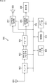
- CAVLC is a method based on a code conversion table.
- the context adaptive variable length encoding unit 11 converts one symbol into a bit string in one cycle.
- CABAC is a method that uses arithmetic codes.
- the binarization unit 21 binarizes the input symbol (binarization of syntaxselement) to generate “bin”, and the arithmetic encoding unit 22 Is converted into a bit string bit by bit. That is, in the case of CABAC, 1 bin is processed per cycle. Therefore, in general, CABAC has better encoding efficiency than CAVLC and is advantageous in terms of image quality (high image quality), but some syntax elements are expanded into multiple bins. CABAC is more difficult to improve throughput performance than CAVLC.
- a CABAC encoder / decoder with an operating frequency of 100 MHz has a processing capacity of approximately 100 Mbin / sec if processing overhead is ignored, since processing of 1 bin per cycle is required unless special measures are taken. Since the size ratio between “bin” and the bitstream (bitstream) as the AVC code string is 4/3, the CABAC encoder / decoder can handle up to 75 Mbps when calculated with this ratio.
- CAVLC and CABAC can be selected as described above.
- CAVLC can be selected when throughput performance exceeding the performance of CABAC is required.
- CABAC CABAC
- the encoding efficiency is reduced compared with the case where CABAC is applied, and the image quality of the decoded image is reduced. If throughput performance exceeding the CABAC performance is required over the entire moving image, there is still no problem, but if it is a part of the moving image that requires a throughput performance exceeding the CABAC performance, it is part of that. If CAVLC is applied to, the coding efficiency is unnecessarily reduced in other parts, and the image quality of the decoded image is reduced.
- CAVLC and CABAC can be selected for each picture. That is, for example, CAVLC can be selected only for pictures that require throughput performance that exceeds CABAC performance.
- the encoding method since the encoding method needs to be selected by the user, the encoding method cannot be selected adaptively based on the encoding / decoding situation. Therefore, for example, when the generated image data is encoded immediately (in real time) or the encoded data is decoded, CAVLC and CABAC may not be appropriately selected. was there. For this reason, in order to prevent encoding / decoding from failing, CAVLC must be selected for all pictures as a safety measure when there is a possibility that even a part of the throughput performance may exceed CABAC performance. . For this reason, the encoding efficiency is unnecessarily reduced, and the image quality of the decoded image may be reduced.
- the encoding method of information related to the image is controlled. For example, based on information related to image encoding, the encoding method of information related to the image may be selected as a predetermined encoding method. By doing in this way, switching of an encoding system can be performed more appropriately according to the situation of encoding and decoding, and the reduction of encoding efficiency can be suppressed.
- this encoding method is arbitrary, for example, variable length encoding or arithmetic encoding may be included.
- the control described above may set variable length coding or arithmetic coding as the coding method.
- control of the encoding method in AVC selection of CABAC or CAVLC
- information relating to image encoding used for this control is also arbitrary.
- this information may include information related to the throughput of image encoding.
- the encoding method of information related to the image may be selected as a predetermined encoding method. By doing in this way, it becomes possible to switch the encoding method more appropriately according to the information regarding the encoding throughput of the image.
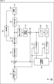
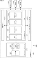
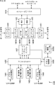
- FIG. 2 is a block diagram illustrating an example of a configuration of an image encoding device that is an aspect of an image processing device to which the present technology is applied.
- the image encoding apparatus 100 illustrated in FIG. 2 encodes moving image image data using AVC prediction processing or prediction processing based on (or similar to) a prediction method.
- FIG. 2 shows main components such as a processing unit and a data flow, and the ones shown in FIG. 2 are not all. That is, in the image coding apparatus 100, there may be a processing unit that is not shown as a block in FIG. 2, or there may be a process or data flow that is not shown as an arrow or the like in FIG.
- the image encoding device 100 includes a screen rearrangement buffer 111, a calculation unit 112, an orthogonal transformation unit 113, a quantization unit 114, an encoding unit 115, and a storage buffer 116.
- the image encoding device 100 includes an inverse quantization unit 117, an inverse orthogonal transform unit 118, a calculation unit 119, a filter 120, a frame memory 121, an intra prediction unit 122, an inter prediction unit 123, a predicted image selection unit 124, and a rate.
- a control unit 125 is included.
- the screen rearrangement buffer 111 stores the images of the frames of the input image data in the display order, and the images of the frames in the stored display order are encoded for encoding according to GOP (Group Of Picture). The images are rearranged in the order of the frames, and the image in which the order of the frames is rearranged is supplied to the calculation unit 112. In addition, the screen rearrangement buffer 111 also supplies the image in which the order of the frames is rearranged to the intra prediction unit 122 and the inter prediction unit 123.
- GOP Group Of Picture
- the calculation unit 112 subtracts the prediction image supplied from the intra prediction unit 122 or the inter prediction unit 123 via the prediction image selection unit 124 from the image read out from the screen rearrangement buffer 111, and the difference between them. Residual information (also referred to as residual data) is obtained. For example, in the case of an image on which intra coding is performed, the calculation unit 112 subtracts the prediction image supplied from the intra prediction unit 122 from the image read from the screen rearrangement buffer 111. For example, in the case of an image on which inter coding is performed, the calculation unit 112 subtracts the prediction image supplied from the inter prediction unit 123 from the image read from the screen rearrangement buffer 111. The calculation unit 112 supplies the obtained residual data to the orthogonal transform unit 113.
- the orthogonal transform unit 113 performs orthogonal transform on the residual data supplied from the calculation unit 112 by a predetermined method.
- the orthogonal transform unit 113 supplies residual data (also referred to as orthogonal transform coefficients) after the orthogonal transform to the quantization unit 114.
- the quantization unit 114 quantizes the orthogonal transform coefficient by a predetermined method.
- the quantization unit 114 sets a quantization parameter according to the target value (target_bitrate) of the code amount supplied from the rate control unit 125, and performs the quantization.
- the quantization unit 114 supplies the quantized residual data (also referred to as quantized data) to the encoding unit 115 and the inverse quantization unit 117.
- the encoding unit 115 encodes the quantized data and generates encoded data.
- the encoding unit 115 can perform the encoding using variable length encoding (for example, CAVLC) or arithmetic encoding (for example, CABAC).
- the encoding unit 115 can control an encoding method for encoding quantized data based on information related to image encoding. That is, the encoding unit 115 can selectively use (switch) CAVLC or CABAC based on information related to image encoding.
- the encoding unit 115 acquires information on the optimal prediction mode from the predicted image selection unit 124. Furthermore, the encoding unit 115 can acquire arbitrary information from an arbitrary processing unit. The encoding unit 115 generates additional information such as a parameter set and header information using these various types of information, and includes (multiplexes) the additional information in the encoded data. The encoding unit 115 supplies the obtained encoded data to the accumulation buffer 116 for accumulation.
- the accumulation buffer 116 temporarily holds the encoded data supplied from the encoding unit 115.
- the accumulation buffer 116 outputs the stored encoded data to the outside of the image encoding apparatus 100 as a bit stream, for example, at a predetermined timing. That is, the accumulation buffer 116 is also a transmission unit that transmits encoded data.
- the inverse quantization unit 117 performs inverse quantization on the quantized data by a method corresponding to the quantization by the quantization unit 114.
- the inverse quantization unit 117 supplies the quantized data (also referred to as orthogonal transform coefficient) after inverse quantization to the inverse orthogonal transform unit 118.
- the inverse orthogonal transform unit 118 performs inverse orthogonal transform on the orthogonal transform coefficient by a method corresponding to the orthogonal transform processing by the orthogonal transform unit 113.
- the inverse orthogonal transform unit 118 supplies the orthogonal transform coefficient (also referred to as restored residual data) subjected to the inverse orthogonal transform to the calculation unit 119.
- the calculation unit 119 adds the predicted image supplied from the intra prediction unit 122 or the inter prediction unit 123 via the predicted image selection unit 124 to the restored residual data, and locally reconstructed image (also called a reconstructed image). For example, in the case of an image on which intra coding is performed, the calculation unit 119 adds the predicted image supplied from the intra prediction unit 122 to the restored residual data. For example, in the case of an image on which inter coding is performed, the calculation unit 119 adds the predicted image supplied from the inter prediction unit 123 to the restored residual data. The calculation unit 119 supplies the obtained reconstructed image to the filter 120 and the intra prediction unit 122.
- the filter 120 performs a filtering process such as a deblocking filter on the reconstructed image as appropriate.
- the filter 120 supplies the filter processing result (referred to as a decoded image) to the frame memory 121.
- the frame memory 121 stores the decoded image in its own storage area. Further, the frame memory 121 supplies the stored decoded image to the inter prediction unit 123 as a reference image at a predetermined timing.
- the intra prediction unit 122 performs intra prediction (intra-screen prediction) that generates a predicted image using the pixel values in the processing target picture that is a reconstructed image supplied as a reference image from the calculation unit 119.
- the intra prediction unit 122 performs this intra prediction in a plurality of intra prediction modes prepared in advance.
- the intra prediction unit 122 generates predicted images in all candidate intra prediction modes, evaluates the cost function value of each predicted image using the input image supplied from the screen rearrangement buffer 111, and selects the optimum mode. select.
- the intra prediction unit 122 selects the optimal intra prediction mode, the intra prediction mode information that is information related to intra prediction such as a prediction image generated in the optimal intra prediction mode, an index indicating the optimal intra prediction mode, and the like
- the cost function value of the optimal intra prediction mode and the like are supplied to the predicted image selection unit 124 as information related to the prediction result.
- the inter prediction unit 123 performs inter prediction processing (motion prediction processing and compensation processing) using the input image supplied from the screen rearrangement buffer 111 and the reference image supplied from the frame memory 121. More specifically, the inter prediction unit 123 performs motion compensation processing according to motion vectors detected by performing motion prediction as inter prediction processing, and generates a predicted image (inter predicted image information). The inter prediction unit 123 performs such inter prediction in a plurality of inter prediction modes prepared in advance. The inter prediction unit 123 generates a prediction image in all candidate inter prediction modes. The inter prediction unit 123 evaluates the cost function value of each prediction image using the input image supplied from the screen rearrangement buffer 111, information on the generated difference motion vector, and the like, and selects an optimal mode.
- inter prediction processing motion prediction processing and compensation processing
- the inter prediction mode is information related to inter prediction such as a prediction image generated in the optimal inter prediction mode, an index indicating the optimal inter prediction mode, and motion information.
- Information, the cost function value of the optimal inter prediction mode, and the like are supplied to the predicted image selection unit 124 as information related to the prediction result.
- the prediction image selection unit 124 acquires information on the above-described prediction result from the intra prediction unit 122 and the inter prediction unit 123.
- the prediction image selection unit 124 selects a prediction mode in the region by selecting any one of them. That is, the predicted image selection unit 124 selects either the (optimal) intra prediction mode or the (optimal) inter prediction mode as the optimal prediction mode.
- the predicted image selection unit 124 supplies the predicted image of the selected mode to the calculation unit 112 and the calculation unit 119. Further, the predicted image selection unit 124 supplies a part or all of the information related to the selected prediction result to the encoding unit 115 as information related to the optimal prediction mode.
- the rate control unit 125 controls the rate of the quantization operation of the quantization unit 114 based on the code amount of the encoded data stored in the storage buffer 116 so that overflow or underflow does not occur.
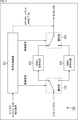
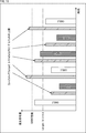
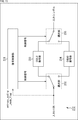
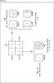
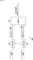
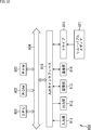
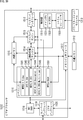
- FIG. 3 is a block diagram illustrating a main configuration example of the encoding unit 115 of FIG.
- the encoding unit 115 includes an encoding control unit 131, a selection unit 132, a CAVLC encoding unit 133, a CABAC encoding unit 134, and a selection unit 135.
- the encoding control unit 131 controls the encoding method of encoding performed by the encoding unit 115.
- the encoding control unit 131 controls the encoding method by supplying a control signal to the selection unit 132 and the selection unit 135 and controlling its operation (switching).
- the selection unit 132 connects one input terminal to one of the two output terminals according to the control signal supplied from the encoding control unit 131. Quantized data supplied from the quantization unit 114 is supplied to the input terminal.
- the CAVLC encoding unit 133 is connected to one output terminal, and the CABAC encoding unit 134 is connected to the other output terminal. That is, the selection unit 132 selects one of the CAVLC encoding unit 133 and the CABAC encoding unit 134 as the supply destination of the input symbol (quantized data supplied from the quantization unit 114).
- the CAVLC encoding unit 133 has a configuration as shown in FIG. 1A, for example, and performs context adaptive variable length encoding. That is, the CAVLC encoding unit 133 uses CAVLC as an encoding method.
- the CAVLC encoding unit 133 converts the input symbol supplied via the selection unit 132 into a bit string using a code conversion table.
- the CAVLC encoding unit 133 supplies the generated encoded data (bit string) to the selection unit 135.
- the CABAC encoding unit 134 has a configuration as shown in FIG. 1B, for example, and performs binarization and arithmetic encoding. That is, the CABAC encoding unit 134 uses CABAC as the encoding method.
- the CABAC encoding unit 134 binarizes the input symbol supplied via the selection unit 132 to generate a bin, and converts the bin into a bit string by arithmetic encoding or the like.
- the CABAC encoding unit 134 supplies the generated encoded data (bit string) to the selection unit 135.
- the selection unit 135 connects one of the two input terminals to the one output terminal in accordance with the control signal supplied from the encoding control unit 131.
- a CAVLC encoding unit 133 is connected to one input terminal, and a CABAC encoding unit 134 is connected to the other input terminal.
- the output terminal is connected to the storage buffer 116. That is, the selection unit 135 selects one of the CAVLC encoding unit 133 and the CABAC encoding unit 134 as the supply source of the output bit string supplied to the accumulation buffer 116.
- the encoding control unit 131 controls the encoding method based on predetermined control conditions.
- This control condition may be anything, but may be other than an instruction from the user.
- the control condition may include information supplied from outside the encoding unit 115, information generated by the encoding unit 115, and the like. Accordingly, the encoding control unit 131 can select the encoding method by controlling the selection unit 132 and the selection unit 135 without an instruction from the user. That is, the encoding control unit 131 can adaptively control the encoding scheme based on the control conditions.
- This control condition may include, for example, information related to image encoding.
- the information related to the image encoding may be any information, but may include information related to the image encoding throughput, for example.
- the information related to the throughput may be any information, but may include information related to the compression rate of image coding, for example.
- the information regarding the compression rate may be any information, but may include information indicating a target bit rate (target bitrate) of image encoding, for example.
- the information regarding the throughput may include information regarding the amount of codes generated by encoding the image, for example.
- the information regarding the code amount may be any information, but may include information indicating the picture type of the picture to be encoded, for example, or may include information indicating the upper limit of the generated code amount. Also good.
- the information indicating the upper limit of the code amount may be supplied from the outside of the encoding unit 115 (for example, the rate control unit 125), or the encoding control unit 131, for example, the rate control unit 125 or the like. It may be calculated on the basis of information such as the amount of code generated in the past supplied from.
- a plurality of information may be included in the control condition. That is, the encoding control unit 131 may control the encoding method based on a plurality of information.
- the encoding control unit 131 can adaptively control the encoding method based on at least one of these pieces of information.
- the encoding control unit 131 sets entropy_coding_mode_flag as information indicating the control result of such an encoding method. That is, the encoding control unit 131 sets the value of entropy_coding_mode_flag to a value indicating the selected encoding method. For example, when CAVLC is selected, the encoding control unit 131 sets the value of entropy_coding_mode_flag to “0”. For example, when CABAC is selected, the encoding control unit 131 sets the value of entropy_coding_mode_flag to “1”. The encoding control unit 131 supplies the entropy_coding_mode_flag to the accumulation buffer 116 as an output bit string (that is, included in the encoded data). Thereby, also on the decoding side, a decoding method corresponding to the encoding method adopted by the encoding control unit 131 can be adopted.
- this entropy_coding_mode_flag is stored in the picture parameter set.
- the encoding control unit 131 can control the encoding method as described above for each picture. That is, the encoding control unit 131 can adaptively control the encoding method for each picture.
- the screen rearrangement buffer 111 stores the images of the frames (pictures) of the input moving image in the order in which the images are displayed. Rearrange in the order of conversion.
- step S102 the encoding unit 115 performs encoding control processing and selects an encoding method for each picture.
- step S103 the intra prediction unit 122, the inter prediction unit 123, and the predicted image selection unit 124 perform a prediction process, and generate a predicted image or the like in the optimal prediction mode. That is, in this prediction process, the intra prediction unit 122 performs intra prediction to generate a prediction image or the like in the optimal intra prediction mode, and the inter prediction unit 123 performs inter prediction to generate a prediction image or the like in the optimal inter prediction mode.
- the predicted image selection unit 124 selects the optimal one of the optimal intra prediction mode and the optimal inter prediction mode based on the cost function value and the like.
- step S104 the calculation unit 112 calculates a difference between the input image whose frame order is rearranged by the process of step S101 and the predicted image of the optimum mode selected by the prediction process of step S103. That is, the calculation unit 112 generates residual data between the input image and the predicted image.
- the residual data obtained in this way is reduced in data amount compared to the original image data. Therefore, the data amount can be compressed as compared with the case where the image is encoded as it is.
- step S105 the orthogonal transform unit 113 performs orthogonal transform on the residual data generated by the process in step S104.
- step S106 the quantization unit 114 quantizes the orthogonal transform coefficient obtained by the process in step S105 by using the quantization parameter calculated by the rate control unit 125.
- step S107 the inverse quantization unit 117 inversely quantizes the quantized data generated by the process in step S106 with a characteristic corresponding to the quantization characteristic in step S106.
- step S108 the inverse orthogonal transform unit 118 performs inverse orthogonal transform on the orthogonal transform coefficient obtained by the process in step S107 by a method corresponding to the orthogonal transform in step S105.
- step S109 the calculation unit 119 generates image data of a reconstructed image by adding the predicted image obtained by the prediction process of step S103 to the residual data restored by the process of step S108.
- step S110 the filter 120 performs a filtering process such as a deblocking filter on the image data of the reconstructed image generated by the process in step S109.
- a filtering process such as a deblocking filter
- step S111 the frame memory 121 stores the locally decoded decoded image obtained by the process in step S110.
- the encoding unit 115 performs an encoding process. That is, the encoding unit 115 encodes the quantized data obtained by the process of step S106 using the encoding method selected by the encoding control process of step S102. That is, the encoding unit 115 encodes quantized data, which is information related to an image, by variable length encoding or arithmetic encoding, and generates encoded data. At this time, the encoding unit 115 also includes information related to the image other than the quantized data corresponding to the residual data, such as information related to the prediction mode selected by the prediction processing in step S103, in the encoded data.
- step S113 the accumulation buffer 116 accumulates the encoded data obtained by the process in step S112.
- the encoded data or the like stored in the storage buffer 116 is appropriately read as a bit stream, for example, and transmitted to the decoding side via a transmission path or a recording medium.
- step S114 the rate control unit 125 performs step S106 so that overflow or underflow does not occur based on the code amount (generated code amount) of encoded data or the like accumulated in the accumulation buffer 116 by the process of step S113. Control the rate of quantization processing.
- step S114 ends, the image encoding process ends.
- processing unit of each of these processes is arbitrary and does not need to be the same. Therefore, the processing of each step can be executed in parallel with the processing of other steps, or the processing order can be changed as appropriate.
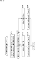
- the encoding control unit 131 determines in step S131 whether the target bit rate of encoding exceeds the CABAC processing capability.
- Information indicating the target bit rate may be acquired from an arbitrary processing unit outside the encoding unit 115 or may be registered in the encoding control unit 131 in advance.
- step S132 If it is determined that the target bit rate exceeds the CABAC processing capability, the process proceeds to step S132.
- the encoding control unit 131 selects CAVLC as the encoding method in step S132, and sends a control signal corresponding to the selection to the selecting unit 132 and This is supplied to the selector 135. More specifically, in this case, the encoding control unit 131 supplies a control signal for connecting the input terminal to the output terminal to which the CAVLC encoding unit 133 is connected, to the selection unit 132.
- the encoding control unit 131 supplies a control signal that causes the selection unit 135 to connect the input terminal to which the CAVLC encoding unit 133 is connected to the output terminal. That is, in this case, variable length coding (CAVLC) is performed as the coding process in step S112 of FIG.
- CAVLC variable length coding
- step S133 When the process of step S133 is completed, the encoding control process is terminated, and the process returns to FIG.
- step S131 of FIG. 5 If it is determined in step S131 of FIG. 5 that the target bit rate of image encoding is equal to or less than the CABAC processing capability, the process proceeds to step S134.
- the encoding control unit 131 selects CABAC as the encoding method in step S134, and sends a control signal corresponding to the selection to the selection unit 132 and This is supplied to the selector 135. More specifically, in this case, the encoding control unit 131 supplies the selection unit 132 with a control signal for connecting the input terminal to the output terminal to which the CABAC encoding unit 134 is connected.
- the encoding control unit 131 supplies a control signal that causes the selection unit 135 to connect the input terminal to which the CABAC encoding unit 134 is connected to the output terminal. That is, in this case, in step S112 in FIG. 4, arithmetic coding (CABAC) is performed (binarization) as coding processing.
- CABAC arithmetic coding
- step S135 When the process of step S135 is completed, the encoding control process is completed, and the process returns to FIG.
- the encoding control unit 131 can adaptively control the image encoding method for each picture according to the target bit rate.
- the code amount of an I picture is larger than that of a P picture or a B picture.
- the difference becomes large.
- the generated code amount of the P picture and B picture is less than the CABAC performance, but the generated code amount of the I picture exceeds the CABAC performance, and the coding may be broken in CABAC. was there.
- CAVLC is used as the encoding method for all pictures, the encoding efficiency may be unnecessarily reduced and the image quality of the decoded image may be reduced.
- CABAC is parallelized, the circuit scale is greatly increased, and not only miniaturization is difficult, but also power consumption and manufacturing cost may increase.
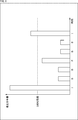
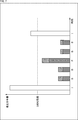
- the encoding scheme is controlled based on information (picture type) indicating the picture type of the picture to be encoded. For example, in the case of the bar graph shown in FIG. 7, CAVLC is selected for an I picture with a large amount of generated code (the generated code amount is likely to exceed CABAC performance), and the generated code amount is small (the generated code amount is CABAC performance). CABAC is selected in the P picture and the B picture. For example, if the bar graph of FIG. 6 is the generated code amount in the case of CAVLC, the generated code amount of the P picture and B picture is the portion shown in gray of the bar graph of FIG. That is, in this case, in the P picture and the B picture, the generated code amount can be reduced by the shaded portion as compared with the CAVLC case (FIG. 6).
- the encoding control unit 131 determines in step S151 whether or not the picture type of the encoding target picture is an I picture.
- the information indicating the picture type may be acquired from, for example, an arbitrary processing unit outside the encoding unit 115, or may be registered in the encoding control unit 131 in advance.
- the encoding control unit 131 selects CAVLC as the encoding method in step S152, and sends a control signal corresponding to the selection to the selecting unit 132 and This is supplied to the selector 135. More specifically, in this case, the encoding control unit 131 supplies a control signal for connecting the input terminal to the output terminal to which the CAVLC encoding unit 133 is connected, to the selection unit 132.
- the encoding control unit 131 supplies a control signal that causes the selection unit 135 to connect the input terminal to which the CAVLC encoding unit 133 is connected to the output terminal. That is, in this case, variable length coding (CAVLC) is performed as the coding process in step S112 of FIG.
- CAVLC variable length coding
- step S153 When the process of step S153 is completed, the encoding control process is terminated, and the process returns to FIG.
- step S151 in FIG. 8 If it is determined in step S151 in FIG. 8 that the picture type of the encoding target picture is not an I picture (P picture or B picture), the process proceeds to step S154.
- the encoding control unit 131 selects CABAC as the encoding method in step S154, and sends a control signal corresponding to the selection to the selection unit 132 and the selection unit 135. Supply. More specifically, in this case, the encoding control unit 131 supplies the selection unit 132 with a control signal for connecting the input terminal to the output terminal to which the CABAC encoding unit 134 is connected.
- the encoding control unit 131 supplies a control signal that causes the selection unit 135 to connect the input terminal to which the CABAC encoding unit 134 is connected to the output terminal. That is, in this case, in step S112 in FIG. 4, arithmetic coding (CABAC) is performed (binarization) as coding processing.
- CABAC arithmetic coding
- step S155 When the process of step S155 is finished, the encoding control process is finished, and the process returns to FIG.
- the encoding control unit 131 can adaptively control the image encoding method for each picture according to the picture type of the picture to be encoded. .
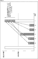
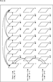
- the coding scheme for P and B pictures becomes CABAC, and thus the amount of generated codes for P and B pictures is reduced as described above. Therefore, as shown in the bar graph shown in FIG. 9, by assigning such a reduction amount (shaded portion) of the generated code amount in the P picture or B picture to the I picture, the image coding apparatus 100 can The target bit rate can be further increased, and image quality reduction can be further suppressed.
- the bit rate for each picture can be controlled according to a specific algorithm. For example, when a picture with a large generated code amount continues, the upper limit of the generated code amount is suppressed, and when a picture with a small generated code amount continues, control such as allowing the generated code amount to increase is controlled. Conceivable. For example, as in the bar graph shown in FIG. 10, a method of controlling the upper limit of the generated code amount so that the average of the generated code amount of two consecutive pictures does not exceed the target bit rate can be considered. In FIG. 10, a diagonal bar graph indicates the upper limit of the generated code amount of the processing target picture.
- the upper limit of the generated code amount of the processing target picture is set so that the average of the generated code amount of the previous picture is equal to or less than the target bit rate (target bitrate). That is, the upper limit of the generated code amount of the processing target picture is suppressed when the generated code amount of the previous picture is large, and is relaxed when the generated code amount is small.
- the encoding scheme is controlled based on the upper limit of the generated code amount of the processing target picture, and the upper limit of the generated code amount of the processing target picture is determined by the CABAC encoding unit 134.
- CAVLC is selected when the processing capacity is exceeded
- CABAC is selected when the processing capacity is not exceeded.
- the encoding control unit 131 sets an upper limit of the generated code amount of the processing target picture by a predetermined bit rate control algorithm in step S171. For example, the encoding control unit 131 acquires information indicating the generated code amount of the past (for example, the previous picture) from the outside of the encoding unit 115 (for example, the rate control unit 125), and performs processing based on the information. Sets the upper limit of the generated code amount of the target picture. Note that the upper limit of the generated code amount of the processing target picture may be obtained outside the encoding unit 115 (for example, the rate control unit 125) and supplied to the encoding control unit 131.
- step S172 the encoding control unit 131 determines whether or not the upper limit of the generated code amount of the processing target picture exceeds the CABAC processing capability.
- step S173 If it is determined that the upper limit of the generated code amount of the processing target picture exceeds the CABAC processing capability, the process proceeds to step S173.
- the encoding control unit 131 selects CAVLC as the encoding method in step S173, and sends a control signal corresponding to the selection to the selecting unit 132 and This is supplied to the selector 135. More specifically, in this case, the encoding control unit 131 supplies a control signal for connecting the input terminal to the output terminal to which the CAVLC encoding unit 133 is connected, to the selection unit 132.
- the encoding control unit 131 supplies a control signal that causes the selection unit 135 to connect the input terminal to which the CAVLC encoding unit 133 is connected to the output terminal. That is, in this case, variable length coding (CAVLC) is performed as the coding process in step S112 of FIG.
- CAVLC variable length coding
- step S174 When the process of step S174 is completed, the encoding control process is terminated, and the process returns to FIG.
- step S172 of FIG. 12 If it is determined in step S172 of FIG. 12 that the upper limit of the generated code amount of the processing target picture is equal to or less than the CABAC processing capability, the process proceeds to step S175.
- the encoding control unit 131 selects CABAC as the encoding method in step S175, and sends a control signal corresponding to the selection to the selection unit 132 and This is supplied to the selector 135. More specifically, in this case, the encoding control unit 131 supplies the selection unit 132 with a control signal for connecting the input terminal to the output terminal to which the CABAC encoding unit 134 is connected.
- the encoding control unit 131 supplies a control signal that causes the selection unit 135 to connect the input terminal to which the CABAC encoding unit 134 is connected to the output terminal. That is, in this case, in step S112 in FIG. 4, arithmetic coding (CABAC) is performed (binarization) as coding processing.
- CABAC arithmetic coding
- step S176 When the process of step S176 is finished, the encoding control process is finished, and the process returns to FIG.
- the encoding control unit 131 can adaptively control the image encoding method for each picture according to the upper limit of the generated code amount of the processing target picture. it can.
- an encoding method of information about an image may be controlled based on a plurality of pieces of information.
- the encoding method of information about an image may be controlled based on the upper limit of the generated code amount of the processing target picture and the picture type.
- the encoding control unit 131 sets an upper limit of the generated code amount of the processing target picture by a predetermined bit rate control algorithm in step S191.
- this algorithm is arbitrary, for example, it may be the same as in the case of the process in step S171 in FIG.
- the upper limit of the generated code amount of the processing target picture may be supplied from outside the encoding unit 115 (for example, the rate control unit 125). Good.
- step S192 the encoding control unit 131 determines whether or not the upper limit of the generated code amount of the processing target picture exceeds the CABAC processing capability.
- step S193 the encoding control unit 131 determines whether the picture type of the picture to be encoded is an I picture.
- the information indicating the picture type may be acquired from, for example, an arbitrary processing unit outside the encoding unit 115, or may be registered in the encoding control unit 131 in advance.
- the process proceeds to step S194.
- the encoding control unit 131 selects CAVLC as the encoding method in step S194 and supplies a control signal corresponding to the selection to the selection unit 132 and the selection unit 135. .
- the encoding control unit 131 supplies a control signal for connecting the input terminal to the output terminal to which the CAVLC encoding unit 133 is connected, to the selection unit 132. Also, the encoding control unit 131 supplies a control signal that causes the selection unit 135 to connect the input terminal to which the CAVLC encoding unit 133 is connected to the output terminal. That is, in this case, variable length coding (CAVLC) is performed as the coding process in step S112 of FIG.
- CAVLC variable length coding
- step S195 ends, the encoding control process ends, and the process returns to FIG.
- step S192 in FIG. 13 If it is determined in step S192 in FIG. 13 that the upper limit of the generated code amount of the processing target picture is equal to or less than the CABAC processing capability, the process proceeds to step S196. If it is determined in step S193 that the picture type of the processing target picture is not an I picture (P picture or B picture), the process proceeds to step S196.
- the encoding control unit 131 selects CABAC as the encoding method in step S196, and the selection is made.
- a corresponding control signal is supplied to the selection unit 132 and the selection unit 135. More specifically, in this case, the encoding control unit 131 supplies the selection unit 132 with a control signal for connecting the input terminal to the output terminal to which the CABAC encoding unit 134 is connected. Also, the encoding control unit 131 supplies a control signal that causes the selection unit 135 to connect the input terminal to which the CABAC encoding unit 134 is connected to the output terminal. That is, in this case, in step S112 in FIG. 4, arithmetic coding (CABAC) is performed (binarization) as coding processing.
- CABAC arithmetic coding
- step S197 When the process of step S197 is completed, the encoding control process is terminated, and the process returns to FIG.
- the encoding control unit 131 adaptively controls the image encoding method for each picture according to the upper limit of the generated code amount of the processing target picture and the picture type. can do.
- the encoding control unit 131 can adaptively control the encoding method based on the information related to image encoding, the encoding unit 115 reduces unnecessary encoding efficiency. Can be suppressed, and a reduction in the image quality of the decoded image can be suppressed. In other words, since it is not necessary to parallelize the CABAC encoding unit 134 by such control, the encoding unit 115 can suppress an increase in circuit scale, and increase in power consumption and manufacturing cost. Can also be suppressed.
- the encoding control unit 131 can notify the decoding side of the control result of the encoding method (designation of the selected encoding method)
- the encoding unit 115 notifies the encoding side of the encoding control unit 131.
- the same encoding method can be selected. That is, the encoding unit 115 can cause the decoding side to correctly decode the encoded data encoded by the encoding unit 115.
- the encoding control unit 131 can control the encoding method based on information that can be acquired by an AVC encoder. Also, the encoding control unit 131 can notify the decoding side of the control result of the encoding method using entropy_coding_mode_flag, which is information compliant with AVC. Therefore, the image encoding apparatus 100 can suppress unnecessary reduction in encoding efficiency and can suppress reduction in image quality of a decoded image in encoding using a method compliant with AVC. Further, an increase in circuit scale can be suppressed, and an increase in power consumption and manufacturing cost can also be suppressed. Then, the image encoding apparatus 100 can correctly decode the encoded data encoded by the image encoding apparatus 100 on the decoding side that performs decoding in a method compliant with AVC.
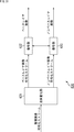
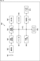
- FIG. 14 is a block diagram illustrating an example of a configuration of an image decoding device that is an aspect of an image processing device to which the present technology is applied.
- An image decoding apparatus 200 shown in FIG. 14 is an image decoding apparatus corresponding to the image encoding apparatus 100 in FIG. 2, and is encoded data (encoded by an AVC compliant method) generated by the image encoding apparatus 100. (Encoded data) is decoded by a decoding method compliant with AVC.
- FIG. 14 shows main components such as a processing unit and a data flow, and the ones shown in FIG. 14 are not limited to all. That is, in the image decoding apparatus 200, there may be a processing unit that is not shown as a block in FIG. 14, or there may be a process or data flow that is not shown as an arrow or the like in FIG.
- the image decoding apparatus 200 includes a storage buffer 211, a decoding unit 212, an inverse quantization unit 213, an inverse orthogonal transform unit 214, a calculation unit 215, a filter 216, and a screen rearrangement buffer 217. Further, the image decoding device 200 includes a frame memory 218, an intra prediction unit 219, an inter prediction unit 220, and a predicted image selection unit 221.
- the encoded data generated by the image encoding device 100 or the like is supplied to the image decoding device 200 as a bit stream or the like via a transmission medium or a recording medium, for example.
- the accumulation buffer 211 accumulates the encoded data and supplies the encoded data to the decoding unit 212 at a predetermined timing.
- the decoding unit 212 decodes the encoded data supplied from the accumulation buffer 211 by a method corresponding to the encoding method of the encoding unit 115 in FIG.
- the decoding unit 212 supplies the quantized data to the inverse quantization unit 213.
- the decoding unit 212 supplies information related to the optimal prediction mode obtained by decoding the encoded data to the intra prediction unit 219 or the inter prediction unit 220. For example, when intra prediction is performed, the decoding unit 212 supplies information regarding the prediction result of the optimal intra prediction mode to the intra prediction unit 219.
- the decoding unit 212 supplies information related to the prediction result of the optimal inter prediction mode to the inter prediction unit 220. Similarly, the decoding unit 212 can appropriately supply various information obtained by decoding the encoded data to various processing units that require the information.
- the inverse quantization unit 213 performs inverse quantization on the quantized data supplied from the decoding unit 212. That is, the inverse quantization unit 213 performs inverse quantization by a method corresponding to the quantization method of the quantization unit 114 in FIG. 2 (that is, the same method as the inverse quantization unit 117).
- the inverse quantization unit 213 supplies the orthogonal transform coefficient obtained by the inverse quantization to the inverse orthogonal transform unit 214.
- the inverse orthogonal transform unit 214 performs inverse orthogonal transform on the orthogonal transform coefficient supplied from the inverse quantization unit 213. That is, the inverse orthogonal transform unit 214 performs inverse orthogonal transform by a method corresponding to the orthogonal transform method of the orthogonal transform unit 113 in FIG. 2 (that is, the same method as the inverse orthogonal transform unit 118). The inverse orthogonal transform unit 214 supplies the residual data (reconstructed residual data) obtained by the inverse orthogonal transform process to the calculation unit 215.
- the calculation unit 215 adds the predicted image supplied from the predicted image selection unit 221 to the restored residual data supplied from the inverse orthogonal transform unit 214 to obtain a reconstructed image.
- the calculation unit 215 supplies the reconstructed image to the filter 216 and the intra prediction unit 219.
- the filter 216 performs the same filter processing (for example, deblocking filter) as the filter 120 of FIG.
- the filter 216 supplies the decoded image that is the filter processing result to the screen rearrangement buffer 217 and the frame memory 218.
- the screen rearrangement buffer 217 rearranges the supplied decoded images. That is, the order of frames rearranged for the encoding order by the screen rearrangement buffer 111 in FIG. 2 is rearranged in the original display order.
- the screen rearrangement buffer 217 outputs the decoded image data in which the frame order is rearranged to the outside of the image decoding device 200.
- the frame memory 218 stores the supplied decoded image.
- the frame memory 218 supplies the stored decoded image or the like to the inter prediction unit 220 at a predetermined timing or based on an external request from the inter prediction unit 220 or the like.
- the intra prediction unit 219 performs intra prediction using information regarding the prediction result of the optimal intra prediction mode supplied from the decoding unit 212 and the reconstructed image supplied from the calculation unit 215, and generates a prediction image. .
- the intra prediction unit 219 supplies the generated predicted image to the predicted image selection unit 221.
- the inter prediction unit 220 performs inter prediction using information on the prediction result of the optimal inter prediction mode supplied from the decoding unit 212 and the decoded image supplied from the frame memory 218, and generates a prediction image.
- the inter prediction unit 220 supplies the generated predicted image to the predicted image selection unit 221.
- the predicted image selection unit 221 supplies the predicted image supplied from the intra prediction unit 219 or the inter prediction unit 220 to the calculation unit 215. For example, when the macroblock to be processed is a macroblock that has been subjected to intra prediction at the time of encoding, intra prediction is performed by the intra prediction unit 219 and a predicted image (intra predicted image) is generated. The predicted image selection unit 221 supplies the intra predicted image to the calculation unit 215. For example, when the macroblock to be processed is a macroblock that has been subjected to inter prediction at the time of encoding, the inter prediction unit 220 performs inter prediction and generates a prediction image (inter prediction image). Therefore, the predicted image selection unit 221 supplies the inter predicted image to the calculation unit 215.
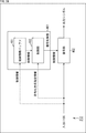
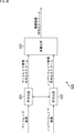
- FIG. 15 is a block diagram illustrating a main configuration example of the decoding unit 212.
- the decoding unit 212 includes a decoding control unit 231, a selection unit 232, a CAVLC decoding unit 233, a CABAC decoding unit 234, and a selection unit 235.
- the decoding control unit 231 controls the decoding method of decoding performed by the decoding unit 212.
- the decoding control unit 231 controls the decoding method by supplying a control signal to the selection unit 232 and the selection unit 235 and controlling its operation (switching).
- the selection unit 232 connects one input terminal to one of the two output terminals according to the control signal supplied from the decoding control unit 231. Encoded data supplied from the accumulation buffer 211 is supplied to the input terminal.
- the CAVLC decoding unit 233 is connected to one output terminal, and the CABAC decoding unit 234 is connected to the other output terminal. That is, the selection unit 232 selects one of the CAVLC decoding unit 233 and the CABAC decoding unit 234 as the supply destination of the input bit string (encoded data supplied from the accumulation buffer 211).
- the CAVLC decoding unit 233 has a configuration corresponding to the configuration of A in FIG. 1, for example, and performs context adaptive variable length decoding. That is, the CAVLC decoding unit 233 uses CAVLC as a decoding method.
- the CAVLC decoding unit 233 converts the input bit string supplied via the selection unit 232 into symbols using a code conversion table.
- the CAVLC decoding unit 233 supplies the generated symbol to the selection unit 235.
- the CABAC decoding unit 234 has a configuration corresponding to the configuration of B in FIG. 1, for example, and performs arithmetic decoding and inverse binarization. That is, the CABAC decoding unit 234 uses CABAC as a decoding method.
- the CABAC decoding unit 234 converts the input bit string supplied via the selection unit 232 into bins by arithmetic decoding or the like, and inverse binarizes the bins to convert them into symbols.
- the CABAC decoding unit 234 supplies the generated symbol to the selection unit 235.
- the selection unit 235 connects either one of the two input terminals to the one output terminal in accordance with the control signal supplied from the decoding control unit 231.
- the CAVLC decoding unit 233 is connected to one input terminal, and the CABAC decoding unit 234 is connected to the other input terminal.
- the output terminal is connected to the inverse quantization unit 213 and the like. That is, the selection unit 235 selects one of the CAVLC decoding unit 233 and the CABAC decoding unit 234 as a supply source of the output symbol (quantized data) to be supplied to the inverse quantization unit 213.
- the decoding control unit 231 refers to entropy_coding_mode_flag stored in the picture parameter set of the encoded data supplied from the accumulation buffer 211, and sets the decoding method to CAVLC or CABAC based on the value. That is, the decoding control unit 231 selects a decoding method specified by the encoding side. Thereby, the decoding control unit 231 can select a decoding method corresponding to the encoding method adopted by the encoding control unit 131. That is, the decoding control unit 231 can realize control of an adaptive encoding scheme (decoding scheme) based on the control conditions.
- the accumulation buffer 211 accumulates the encoded data supplied to the image decoding apparatus 200 in step S201.
- the decoding unit 212 performs a decoding control process and sets a decoding method.
- the decoding unit 212 decodes the encoded data stored in step S201 by the decoding method set in step S202, and obtains quantized data.
- step S204 the inverse quantization unit 213 inversely quantizes the quantized data obtained by the process in step S203 to obtain orthogonal transform coefficients.
- step S205 the inverse orthogonal transform unit 214 obtains residual data restored by performing inverse orthogonal transform on the orthogonal transform coefficient obtained by the process of step S204.
- the intra prediction unit 219, the inter prediction unit 220, and the predicted image selection unit 221 perform prediction processing in a prediction mode at the time of encoding, and generate a predicted image.
- the intra prediction unit 219 when the macroblock to be processed is a macroblock for which intra prediction has been performed at the time of encoding, the intra prediction unit 219 generates an intra prediction image, and the prediction image selection unit 221 uses the intra prediction image as a prediction image.
- the inter prediction unit 220 generates an inter prediction image
- the prediction image selection unit 221 selects the inter prediction image. Select as predicted image.
- step S207 the computing unit 215 adds the predicted image obtained by the process of step S206 to the restored residual data obtained by the process of step S205, and obtains a reconstructed image.
- step S208 the filter 216 performs a filtering process such as a deblocking filter on the reconstructed image obtained by the process in step S207 to obtain a decoded image.
- a filtering process such as a deblocking filter
- step S209 the screen rearrangement buffer 217 rearranges the decoded images obtained by the processing in step S208, and changes the frame order to the original display order (the screen rearrangement buffer 111 of the image encoding device 100 has Sort in the order before sorting).
- step S210 the frame memory 218 stores the decoded image obtained by the process in step S208. This decoded image is used as a reference image in inter prediction.
- step S210 When the process of step S210 is completed, the image decoding process is ended.
- the decoding control unit 231 selects CAVLC as the decoding method in step S222 and supplies a control signal corresponding to the selection to the selection unit 232 and the selection unit 235. More specifically, in this case, the decoding control unit 231 supplies a control signal for connecting the input terminal to the output terminal to which the CAVLC decoding unit 233 is connected, to the selection unit 232. In addition, the decoding control unit 231 supplies a control signal for connecting the input terminal to which the CAVLC decoding unit 233 is connected to the output terminal to the selection unit 235. That is, in this case, variable length decoding (CAVLC) is performed as decoding processing in step S203 of FIG.
- CAVLC variable length decoding
- step S222 When the process of step S222 is completed, the decoding control process is terminated, and the process returns to FIG.
- CABAC is adopted as an encoding method at the time of encoding. Therefore, in step S223, the decoding control unit 231 selects CABAC as the decoding method, and supplies a control signal corresponding to the selection to the selection unit 232 and the selection unit 235. More specifically, in this case, the decoding control unit 231 supplies a control signal for connecting the input terminal to the output terminal to which the CABAC decoding unit 234 is connected, to the selection unit 232. In addition, the decoding control unit 231 supplies a control signal that causes the selection unit 235 to connect the input terminal to which the CABAC decoding unit 234 is connected to the output terminal. That is, in this case, arithmetic decoding (and inverse binarization) (CABAC) is performed as decoding processing in step S203 of FIG.
- CABAC arithmetic decoding (and inverse binarization)
- step S223 the decoding control process is terminated, and the process returns to FIG.
- the decoding control unit 231 can adaptively control the decoding method of the encoded data for each picture in accordance with entropy_coding_mode_flag. That is, since the decoding control unit 231 can select a decoding method corresponding to the encoding method employed by the encoding control unit 131, control of the adaptive encoding method (decoding method) based on the control condition is realized. can do.
- the decoding unit 212 can correctly decode the encoded data encoded by the encoding unit 115, it is possible to suppress unnecessary reduction in encoding efficiency and suppress reduction in image quality of a decoded image. Can do. In other words, since the CABAC decoding unit 234 need not be parallelized by such control, the decoding unit 212 can suppress an increase in circuit scale, and also suppress an increase in power consumption and an increase in manufacturing cost. can do.
- the decoding control unit 231 can control the decoding method based on entropy_coding_mode_flag, which is information compliant with AVC. Therefore, the image decoding apparatus 200 can realize unnecessary suppression of reduction in encoding efficiency and can suppress reduction in image quality of a decoded image in decoding using a method compliant with AVC. Further, an increase in circuit scale can be suppressed, and an increase in power consumption and manufacturing cost can also be suppressed.
- the present technology is applied when image data is encoded by a method compliant with AVC, or when the encoded data is decoded by a method compliant with AVC.
- the present technology can also be applied to any encoding / decoding other than AVC, such as HEVC (High Efficiency Video Coding).
- the rearrangement of the frames may be omitted.
- the screen rearrangement buffer 111 and the screen rearrangement buffer 217 may be omitted.
- the input image may be encoded without using the predicted image.
- the calculation unit 112 and the inverse quantization unit 117 to the predicted image selection unit 124 may be omitted.
- the calculation unit 215 and the frame memory 218 to the predicted image selection unit 221 may be omitted.
- orthogonal transformation and inverse orthogonal transformation is arbitrary.
- orthogonal transformation / inverse orthogonal transformation such as discrete cosine transformation or Karhunen-Labe transformation may be performed.
- orthogonal transformation and inverse orthogonal transformation may be omitted.
- the orthogonal transform unit 113, the inverse orthogonal transform unit 118, and the inverse orthogonal transform unit 214 may be omitted.
- quantization and inverse quantization methods are arbitrary. Further, quantization and inverse quantization may be omitted. In this case, the quantization unit 114, the inverse quantization unit 117, and the inverse quantization unit 213 may be omitted.
- accumulation of encoded data may be omitted.
- the accumulation buffer 116 and the accumulation buffer 211 may be omitted.
- the filter 120 and the filter 216 may perform any filter processing.
- the filter 120 and the filter 216 may perform image quality improvement by performing an adaptive loop filter process using a Wiener filter.
- the filter 120 and the filter 216 perform sample adaptive offset (SAO (Sample Adaptive Offset)) processing, thereby reducing linking caused by the motion compensation filter and shifting of pixel values that may occur on the decoding screen.
- the image quality may be improved by correcting.
- filter processing other than these may be performed.
- a plurality of filter processes may be performed.
- the filtering process may be omitted. In that case, the filter 120 and the filter 216 may be omitted.
- the prediction processing method for generating the prediction image is arbitrary.
- a predicted image may be generated by a method other than intra prediction and inter prediction.
- intra prediction may not be performed.
- the intra prediction unit 122 and the intra prediction unit 219 may be omitted.
- inter prediction may not be performed.
- the inter prediction unit 123 and the inter prediction unit 220 may be omitted.
- the number of prediction processes for generating a predicted image is arbitrary, and may be one or three or more.
- the image coding apparatus 100 includes three or more prediction units that perform prediction processes using different prediction methods, and the predicted image selection unit 124 selects an optimum one from the three or more predicted images generated by the prediction units. You may make it select.
- the image decoding apparatus 200 may also include three or more prediction units, and the predicted image selection unit 221 may select a predicted image generated by any one of the prediction units. Note that when there is a single prediction method, the predicted image selection unit 124 and the predicted image selection unit 221 may be omitted.
- the rate control may not be performed. In that case, the rate control unit 125 may be omitted.
- the encoding method by the encoding unit 115 and the decoding method by the decoding unit 212 are arbitrary, and are not limited to the above-described examples.
- the encoding unit 115 and the decoding unit 212 may perform processing (encoding or decoding) in an arbitrary unit other than the macroblock.
- the coding process is executed in units of processing called macroblocks.
- the macro block is a block having a uniform size of 16 ⁇ 16 pixels.
- the encoding process is executed in a processing unit (coding unit) called CU (Coding Unit).
- the CU is a block having a variable size formed by recursively dividing an LCU (Largest Coding Unit) that is a maximum coding unit.
- the maximum selectable CU size is 64x64 pixels.
- the minimum selectable CU size is 8x8 pixels.
- the CU of the minimum size is called SCU (Smallest Coding Unit).
- Prediction processing for predictive coding is executed in a processing unit (prediction unit) called PU (Prediction Unit).
- the PU is formed by dividing the CU by one of several division patterns.
- the orthogonal transformation process is executed in a processing unit (transformation unit) called TU (Transform Unit).
- a TU is formed by dividing a CU or PU to a certain depth.
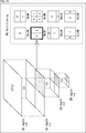
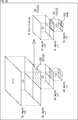
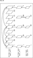
- FIG. 18 is an explanatory diagram for explaining an outline of recursive block division for a CU in HEVC.
- An entire quadtree is called a CTB (Coding Tree Block), and a logical unit corresponding to the CTB is called a CTU (Coding Tree Unit).
- C01 which is a CU having a size of 64 ⁇ 64 pixels is shown as an example.
- the division depth of C01 is equal to zero. This means that C01 is the root of the CTU and corresponds to the LCU.
- the LCU size can be specified by a parameter encoded in SPS (Sequence Parameter Set) or PPS (Picture Parameter Set).
- C02 which is a CU is one of four CUs divided from C01 and has a size of 32 ⁇ 32 pixels.
- the division depth of C02 is equal to 1.
- C03 which is a CU, is one of four CUs divided from C02 and has a size of 16 ⁇ 16 pixels.
- the division depth of C03 is equal to 2.
- C04 which is a CU, is one of the four CUs divided from C03 and has a size of 8 ⁇ 8 pixels.
- the division depth of C04 is equal to 3.
- the CU is formed by recursively dividing an image to be encoded.
- the depth of division is variable. For example, a CU having a larger size (that is, a smaller depth) can be set in a flat image region such as a blue sky. On the other hand, a CU having a smaller size (that is, having a large depth) can be set in a steep image area including many edges.
- Each set CU is a processing unit of the encoding process.
- PU is a processing unit of prediction processing including intra prediction and inter prediction.
- the PU is formed by dividing the CU by one of several division patterns.
- FIG. 19 is an explanatory diagram for describing setting of a PU to the CU illustrated in FIG.
- eight types of division patterns 2Nx2N, 2NxN, Nx2N, NxN, 2NxnU, 2NxnD, nLx2N, and nRx2N.
- two types of 2Nx2N and NxN can be selected in intra prediction (NxN can be selected only in the SCU).
- the inter prediction when asymmetric motion division is enabled, all of the eight types of division patterns can be selected.
- TU is a processing unit of orthogonal transform processing.
- a TU is formed by dividing a CU (for an intra CU, each PU in the CU) to a certain depth.
- FIG. 20 is an explanatory diagram for explaining the setting of the TU to the CU illustrated in FIG.
- the right side of FIG. 20 shows one or more TUs that can be set to C02.
- T01 which is a TU
- T02 which is a TU
- T03 which is a TU, has a size of 8 ⁇ 8 pixels
- the depth of the TU division is equal to 2.
- the block division to be performed in order to set the blocks such as CU, PU, and TU described above to an image is typically determined based on a cost comparison that affects coding efficiency. For example, the encoder compares the cost between one 2Mx2M pixel CU and four MxM pixel CUs, and if the encoding efficiency is higher when four MxM pixel CUs are set, the encoder is 2Mx2M pixel CU. Is divided into 4 MxM pixel CUs.
- FIG. 21 is an explanatory diagram for explaining the scanning order of CU and PU.
- C10, C11, C12, and C13 which are four CUs that can be included in one CTB, are shown.
- the numbers in the frame of each CU express the order of processing.
- the encoding process is executed in the order of C10 which is the upper left CU, C11 which is the upper right CU, C12 which is the lower left CU, and C13 which is the lower right CU.
- the right side of FIG. 21 shows one or more PUs for inter prediction that can be set to C11 which is a CU.
- one or more PUs for intra prediction that can be set to C12 that is a CU are shown.
- the PUs are also scanned from left to right and from top to bottom.
- the encoding unit 115 and the decoding unit 212 may perform processing (encoding or decoding) using CU, LCU, SCU, PU, TU, and the like as processing units.
- block may be used as a partial area or processing unit of an image (picture) (not a block of a processing unit).
- the “block” in this case indicates an arbitrary partial area in the picture, and its size, shape, characteristics, and the like are not limited.
- the “block” in this case includes an arbitrary area (processing unit) such as TU, PU, SCU, CU, LCU, sub-block, macroblock, or slice.
- FIG. 22 is a block diagram illustrating another configuration example of the encoding unit 115 in FIG. 22 .
- the encoding unit 115 shown in FIG. 22 is not limited to AVC, and can be applied to any image encoding method.
- the encoding unit 115 includes an encoding control unit 301 and an encoding unit 302.
- the encoding control unit 301 controls the encoding method of encoding performed by the encoding unit 302.
- the encoding control unit 301 controls the encoding method by supplying a control signal to the encoding unit 302 and controlling its operation (encoding method switching).
- the encoding unit 302 Based on the control signal, the encoding unit 302 encodes the input symbol by the encoding method set by the encoding control unit 301 and converts it into an output bit string.
- the encoding unit 302 can perform encoding for each arbitrary processing unit. For example, the encoding unit 302 may perform encoding for each block.
- the encoding method (that is, selectable encoding method) supported by the encoding unit 302 is arbitrary.
- the encoding unit 302 only needs to support a plurality of encoding methods (the encoding method only needs to be selected).
- the encoding unit 302 may be able to perform encoding using CAVLC or CABAC, or may be able to perform encoding using other encoding methods.
- the encoding unit 302 may be able to perform one type of encoding in parallel.
- the parallel number may be an option of the encoding method. That is, the parallel number of encoding may be adaptively controlled (switched). As a result, an unnecessary increase in encoding processing load, power consumption, and the like can be suppressed.
- the number of encoding methods supported by the encoding unit 302 (the number of options for the encoding method) is arbitrary, and may be three or more.
- the encoding control unit 301 includes a control information setting unit 311 and an encoding method setting unit 312.
- the control information setting unit 311 generates control information for controlling the setting of the encoding method based on a predetermined control setting condition.
- control setting conditions used for generating this control information may be obtained from anywhere.
- this control condition may include information supplied from outside the encoding unit 115 other than the user, or may include information generated in the encoding unit 115.
- Information set by the user may be included.
- the contents of the control setting conditions are arbitrary.
- control information setting unit 311 generates control information is higher than the processing unit in which the encoding scheme setting unit 312 sets the encoding scheme (the processing unit in which the encoding scheme is set).
- the control information setting unit 311 generates control information using a CU, an LCU, a tile, a slice, a picture, a GOP, a component, a sequence, a layer of hierarchical coding, a view of multi-view coding, or the like as a processing unit. It may be.
- control information setting unit 311 includes a plurality of CUs, a plurality of LCUs, a plurality of tiles, a plurality of slices, a plurality of pictures, a plurality of GOPs, a plurality of components, a plurality of sequences, a plurality of layers of hierarchical encoding, or a plurality of multiview encodings.
- Control information may be generated using a view or the like as a processing unit.
- control information may include information that permits (or prohibits) control (switching) of the encoding method within the target processing unit.
- an enable flag (enabled_flag) may be provided as control information, and only when the value of this flag is “1”, control (switching) of the encoding method within the processing unit may be permitted.
- a disable flag (disabled_flag) is provided as control information, and only when the value of this flag is “1”, control (switching) of the encoding method within the processing unit is prohibited. Good.
- control information may include information that permits (or prohibits) the adoption of a predetermined encoding method within the target processing unit.
- it may be information that specifies an encoding method that permits (or prohibits) the adoption, or information that specifies permission (or prohibition) of the adoption for each encoding method.
- control information may include information specifying a default encoding method (that is, an initial value) within the target processing unit.
- a default encoding method that is, an initial value
- the encoding method setting unit 312 does not set the encoding method
- the default encoding method may be set.
- control information includes information that specifies a size range (for example, the minimum size or the maximum size, or both) of the processing unit that is permitted to control the encoding method within the target processing unit. It may be included. For example, when this control information is set, the encoding method may be controlled (switched) only in the processing unit within the range. Of course, it is also possible to specify a range in which the encoding method control is prohibited.
- a size range for example, the minimum size or the maximum size, or both
- a size range for example, a minimum size or a maximum size, or both
- Information to be specified may be included. For example, it may be information that specifies an encoding method that is permitted (or prohibited) to be adopted and its size range, or may be information that specifies a size range for each encoding method. Good.
- control information setting unit 311 may appropriately set such control information in a processing unit of a plurality of hierarchies. For example, such control information may be set as appropriate in each of a sequence, a picture, and a slice. Then, when control information is set in a plurality of hierarchies, the contents of control information in lower layers may be prioritized.
- the encoding control unit 301 supplies the generated control information to the encoding method setting unit 312. Thereby, the encoding method setting unit 312 can set the encoding method based on the control information. Also, the encoding control unit 301 supplies the generated control information to the accumulation buffer 116 as an output bit string (that is, included in the encoded data). Accordingly, the decoding side can be controlled on the decoding side based on the same control information as that on the encoding side.
- control information may be stored in an arbitrary place in the encoded data.
- the control information may be stored in a parameter set or header information of encoded data.
- the control information may be stored in the parameter set or header information of the hierarchy of the target processing unit of the encoded data, or parameters higher than the hierarchy of the target processing unit. It may be stored together in sets and header information.
- the encoding scheme setting unit 312 performs encoding scheme setting (that is, encoding scheme control) based on control information supplied from the control information setting unit 311 and predetermined control conditions.
- This control condition may be obtained from anywhere.
- this control condition may include information supplied from outside the encoding unit 115 other than the user, or may include information generated in the encoding unit 115.
- control condition may include information related to image encoding, or may include other information.
- content of the information regarding the encoding of an image is arbitrary.
- the information related to the image encoding may include information related to the image encoding throughput, or may include other information.
- content of the information regarding this throughput is arbitrary.
- the information related to the throughput may include information related to the compression rate of image encoding, may include information related to the amount of code generated by image encoding, or other information. May be included.
- the content of the information regarding the compression rate and the code amount is arbitrary.
- Information that directly indicates the compression rate and code amount may be used, or information that is indirectly indicated.
- the information regarding the compression rate may include information indicating a target bit rate (target bit rate) of image encoding, or may include other information.
- the information regarding the code amount may include information indicating the picture type of the picture to be encoded, or may include information indicating the upper limit of the generated code amount. Information other than these may be included.
- information indicating a block size information indicating a prediction mode, information indicating a slice type, information indicating a GOP configuration, information indicating a component, information indicating a sequence, information indicating a layer of hierarchical coding, or many Information indicating a view of view encoding may be included.
- a plurality of information may be included in the control condition. That is, the encoding method setting unit 312 may set the encoding method based on a plurality of control conditions. That is, the encoding scheme setting unit 312 can adaptively control the encoding scheme based on at least one of these pieces of information.
- the encoding scheme setting unit 312 sets the encoding scheme based also on the control information supplied from the control information setting unit 311.
- the contents of this control information and how to set the encoding method based on the control information are arbitrary.
- the encoding method setting unit 312 when the setting (switching) of the encoding method is not permitted by the control information, or when the setting (switching) of the encoding method is prohibited, the encoding method setting unit 312 performs encoding based on the control condition.
- the setting (switching) of the conversion method may be omitted.
- the encoding method setting unit 312 is set as the control condition.
- the setting (switching) of the encoding method based on the above may be performed.
- the encoding method setting unit 312 when setting (adopting) of a predetermined encoding method is not permitted by the control information, or when setting (adopting) of the encoding method is prohibited, the encoding method setting unit 312 The encoding method may be excluded from the candidates. In other words, the encoding scheme setting unit 312 uses only the encoding schemes that are permitted to be set (adopted) by the control information or the encoding schemes that are not prohibited to be set (adopted) as candidates for the control condition. The setting (switching) of the encoding method based on the above may be performed. By controlling the encoding scheme setting process in this way, unnecessary encoding schemes can be excluded from the candidates, so that the encoding unit 115 suppresses an increase in the encoding processing load and consumes power. Can be suppressed.
- the encoding method setting unit 312 may be able to omit setting (switching) of the encoding method. .
- the default encoding method specified by the control information is set (adopted).
- the encoding scheme setting unit 312 When the encoding scheme is set, the encoding scheme setting unit 312 generates encoding scheme designation information indicating the encoding scheme and includes it in the encoded data, as will be described later.
- the processing unit in which the setting (switching) of the encoding method is omitted as described above since the encoding method designation information is omitted, an increase in the code amount can be suppressed accordingly. Even in this case, when the encoding method setting unit 312 sets (switches) the encoding method, the setting is prioritized. That is, encoding scheme designation information indicating the encoding scheme set (adopted) by the encoding scheme setting unit 312 is generated.
- the size range for example, the minimum size or the maximum size, or both
- the size is within the size range.
- the coding method setting unit 312 may set (switch) the coding method based on the control condition.
- the encoding method setting unit 312 may omit setting (switching) of the encoding method based on the control condition.
- the coding method setting unit 312 may set (switch) the coding method based on the control condition. In other words, in the processing unit within the size range, the encoding method setting unit 312 may omit setting (switching) of the encoding method based on the control condition.
- the encoding method The setting unit 312 may set the encoding method as a candidate only for a processing unit within the size range in the setting (switching) of the encoding method. In other words, in the processing unit outside the size range, the encoding method may be excluded from the candidates.
- the encoding method may set the encoding method as a candidate only in a processing unit outside the size range in the setting (switching) of the encoding method. In other words, in the processing unit within the size range, the coding method may be excluded from the candidates.
- the encoding method setting unit 312 when the encoding method setting unit 312 selects an encoding method from a plurality of candidates, the encoding method setting unit 312 supplies a control signal corresponding to the control result to the encoding unit 302. Based on this control signal, the encoding unit 302 performs encoding using the encoding method selected by the encoding method setting unit 312.
- the processing unit in which the encoding method setting unit 312 controls the encoding method is a higher processing unit than the encoding processing unit by the encoding unit 302 (a processing unit larger than the encoding processing unit).
- the coding scheme setting unit 312 is a processing unit for TU, PU, CU, SCU, LCU, tile, slice, picture, GOP, component, sequence, layer of hierarchical coding, view of multi-view coding, etc.
- the encoding method may be set as follows.
- the encoding scheme setting unit 312 includes multiple TUs, multiple PUs, multiple CUs, multiple SCUs, multiple LCUs, multiple tiles, multiple slices, multiple pictures, multiple GOPs, multiple components, multiple sequences, and multiple hierarchical encodings.
- the encoding method may be set using a layer or a plurality of views of multi-viewpoint encoding as a processing unit.
- the encoding method setting unit 312 may be able to perform such setting (switching) of the encoding method in any of a plurality of hierarchical processing units. That is, the processing unit (hierarchy) in which the encoding method is set (switched) may be variable. For example, the coding method setting unit 312 selects a processing unit for setting (switching) the coding method from processing units of a plurality of layers such as TU, PU, CU, SCU, LCU, tile, slice, and picture. You may be able to do that.
- the coding scheme setting unit 312 generates coding scheme designation information that designates the selected (adopted) coding scheme as information indicating the control result of such a coding scheme.
- the specification of this encoding method designation information is arbitrary. For example, flag information such as entropy_coding_mode_flag may be used.
- the encoding scheme setting unit 312 supplies the generated encoding scheme designation information to the accumulation buffer 116 as an output bit string (that is, included in the encoded data). Thereby, on the decoding side, it is possible to select (adopt) a decoding method corresponding to the encoding method on the encoding side.
- this encoding method designation information may be stored in an arbitrary location of the encoded data.
- the encoding method designation information may be stored in a parameter set or header information of encoded data.
- the encoding method designation information may be stored in the parameter set or header information of the hierarchy of the processing unit that is the target of the coding method designation information of the encoded data. It may be stored together in a parameter set or header information that is higher than the hierarchy of the processing unit that is the target of the conversion method designation information.
- control information setting unit 311 sets control information based on the control setting condition in step S301, and transmits the control information in association with the encoded data.
- step S302 the encoding method setting unit 312 may switch the encoding method for a processing unit (for example, a block) to be processed based on the control information set in step S301 (or from a predetermined threshold). Large). If it is determined that there is a possibility of switching the encoding method (or greater than a predetermined threshold), the process proceeds to step S303.
- a processing unit for example, a block
- step S303 the encoding scheme setting unit 312 sets an encoding scheme for the processing unit to be processed based on the control conditions and control information, generates encoding scheme designation information indicating the encoding scheme, Is supplied to the encoding unit 302 and transmitted in association with the encoded data.
- step S303 When the process of step S303 is completed, the encoding control process is terminated, and the process returns to FIG.
- step S302 of FIG. 23 If it is determined in step S302 of FIG. 23 that there is no possibility of switching the encoding method (or less than a predetermined threshold) for the processing target unit (for example, block), the process of step S303 is omitted. Then, the encoding control process ends, and the process returns to FIG. That is, processing such as encoding system setting (switching), encoding system designating information generation, and transmission is omitted.
- the encoding control unit 301 can adaptively control the image encoding method according to control setting conditions and control conditions. Therefore, the encoding unit 115 can suppress unnecessary reduction in encoding efficiency and suppress the reduction in image quality of the decoded image. In other words, the encoding unit 115 can suppress an increase in circuit scale, and can also suppress an increase in power consumption and an increase in manufacturing cost.
- the encoding unit 115 uses the encoding method adopted by the encoding control unit 131 on the decoding side. A corresponding decoding method can be selected. That is, the encoding unit 115 can cause the decoding side to correctly decode the encoded data encoded by the encoding unit 115.
- FIG. 24 is a block diagram illustrating another configuration example of the decoding unit 212 of FIG.
- the decoding unit 212 shown in FIG. 24 is not limited to AVC, and can be applied to any image coding method.
- the decoding unit 212 includes a decoding control unit 401 and a decoding unit 402.
- the decoding control unit 401 controls the decoding method of decoding performed by the decoding unit 402.
- the decoding control unit 401 controls the decoding method by supplying a control signal to the decoding unit 402 and controlling its operation (decoding method switching).
- the decoding unit 402 decodes the input bit string by the decoding method set by the decoding control unit 401 and converts it into an output symbol.
- the decoding unit 402 can perform decoding for each arbitrary processing unit. For example, the decoding unit 402 may perform decoding for each block.
- the decoding unit 402 can select at least a decoding method corresponding to an encoding method that can be selected by the encoding unit 302. As long as this is the case, the decoding method that the decoding unit 402 supports (selectable) is arbitrary.
- the decoding control unit 401 includes a control information buffer 411 and a control unit 412.
- the control information buffer 411 acquires and stores control information included in the supplied encoded data (input bit string).
- the decoding control unit 401 supplies a part or all of the stored control information to the control unit 412 at a predetermined timing or in response to a request from the control unit 412 or the like.
- the control unit 412 sets the decoding method of the decoding process by the decoding unit 402 based on the control information read from the control information buffer 411 and the encoding method designation information included in the supplied encoded data (input bit string). (Switch).
- control unit 412 selects a decoding method corresponding to the encoding method specified by the encoding method specifying information. That is, it is possible to select a decoding method corresponding to the encoding method employed in the encoding unit 302.
- the control unit 412 supplies a control signal for designating the decoding method to the decoding unit 402. That is, the decoding unit 402 can correctly decode the encoded data.
- control unit 412 controls such setting (switching) of the decoding method based on the control information read from the control information buffer 411. That is, the control unit 412 can perform the same control as that of the encoding method setting unit 312 in setting (switching) the decoding method. By doing so, the decoding unit 402 can correctly decode the encoded data. In addition, the decoding unit 212 can suppress an increase in processing load related to decoding and suppress an increase in power consumption.
- the decoding unit 212 can realize control of an adaptive encoding scheme (decoding scheme) based on the control setting condition and the control condition.
- control information buffer 411 of the decoding unit 212 acquires control information from the encoded data (input bit string) and holds it in step S401.
- step S402 based on the control information acquired in step S401, the control unit 412 determines whether there is a possibility of switching the encoding method in the processing target processing unit (for example, a block or the like). If it is determined that there is a possibility, the process proceeds to step S403.
- the processing target processing unit for example, a block or the like
- step S403 the control unit 412 acquires encoding method designation information from encoded data (input bit string).
- step S404 the control unit 412 controls the decoding unit 402 to perform decoding using a decoding method corresponding to the encoding method specified by the encoding method specifying information acquired in step S403.
- step S404 the decoding control process is terminated, and the process returns to FIG.
- step S402 in FIG. 25 If it is determined in step S402 in FIG. 25 that there is no possibility of switching the encoding method, the processes in steps S403 to S404 are omitted, the decoding control process ends, and the process returns to FIG. That is, processing such as reference to encoding method designation information and setting (switching) of a decoding method based on the reference is omitted.
- the decoding control unit 401 can adaptively control the decoding method of the encoded data according to the control information and the encoding method designation information. That is, since the decoding control unit 401 can select a decoding method corresponding to the encoding method adopted by the encoding control unit 301, an adaptive encoding method (decoding method) based on the control setting condition or the control condition. Can be realized.
- the decoding unit 212 can correctly decode the encoded data encoded by the encoding unit 115, it is possible to suppress unnecessary reduction in encoding efficiency and suppress reduction in image quality of a decoded image. Can do. In other words, by such control, the decoding unit 212 can suppress an increase in circuit scale, and can also suppress an increase in power consumption and an increase in manufacturing cost.
- This technology is, for example, MPEG, H.264.
- image information is compressed by orthogonal transform such as discrete cosine transform and motion compensation, such as 26x, and the bit stream is transmitted via network media such as satellite broadcasting, cable television, the Internet, or mobile phones
- orthogonal transform such as discrete cosine transform and motion compensation, such as 26x
- the bit stream is transmitted via network media such as satellite broadcasting, cable television, the Internet, or mobile phones
- the present invention can be applied to image processing apparatuses used in
- the present technology can be applied to an image processing device used when processing on a storage medium such as an optical, magnetic disk, and flash memory.
- FIG. 26 shows an example of the multi-view image encoding method.
- the multi-viewpoint image includes images of a plurality of viewpoints (views).
- the multiple views of this multi-viewpoint image are encoded using the base view that encodes and decodes using only the image of its own view without using the information of other views, and the information of other views.
- -It consists of a non-base view that performs decoding.
- Non-base view encoding / decoding may use base view information or other non-base view information.
- the multi-view image is encoded for each viewpoint.
- the encoded data of each viewpoint is decoded (that is, for each viewpoint).
- the method described in each of the above embodiments may be applied to such viewpoint encoding / decoding. By doing so, it is possible to suppress a reduction in encoding efficiency. That is, similarly, in the case of a multi-viewpoint image, it is possible to suppress a reduction in encoding efficiency.
- FIG. 27 is a diagram illustrating a multi-view image encoding apparatus of the multi-view image encoding / decoding system that performs the above-described multi-view image encoding / decoding.
- the multi-view image encoding apparatus 600 includes an encoding unit 601, an encoding unit 602, and a multiplexing unit 603.
- the encoding unit 601 encodes the base view image and generates a base view image encoded stream.
- the encoding unit 602 encodes the non-base view image and generates a non-base view image encoded stream.
- the multiplexing unit 603 multiplexes the base view image encoded stream generated by the encoding unit 601 and the non-base view image encoded stream generated by the encoding unit 602 to generate a multi-view image encoded stream. To do.
- FIG. 28 is a diagram illustrating a multi-view image decoding apparatus that performs the above-described multi-view image decoding.
- the multi-view image decoding device 610 includes a demultiplexing unit 611, a decoding unit 612, and a decoding unit 613.
- the demultiplexing unit 611 demultiplexes the multi-view image encoded stream in which the base view image encoded stream and the non-base view image encoded stream are multiplexed, and the base view image encoded stream and the non-base view image The encoded stream is extracted.
- the decoding unit 612 decodes the base view image encoded stream extracted by the demultiplexing unit 611 to obtain a base view image.
- the decoding unit 613 decodes the non-base view image encoded stream extracted by the demultiplexing unit 611 to obtain a non-base view image.
- the image encoding device 100 described in each of the above embodiments is applied as the encoding unit 601 and the encoding unit 602 of the multi-view image encoding device 600. May be.
- the method described in each of the above embodiments can be applied to the encoding of multi-viewpoint images. That is, a reduction in encoding efficiency can be suppressed.
- the image decoding device 200 described in each of the above embodiments may be applied as the decoding unit 612 and the decoding unit 613 of the multi-view image decoding device 610.
- the method described in each of the above embodiments can be applied to decoding of encoded data of a multi-viewpoint image. That is, a reduction in encoding efficiency can be suppressed.
- FIG. 29 shows an example of a hierarchical image encoding method.
- Hierarchical image coding is a method in which image data is divided into a plurality of layers (hierarchization) so as to have a scalability function with respect to a predetermined parameter, and is encoded for each layer.
- the hierarchical image encoding (scalable decoding) is decoding corresponding to the hierarchical image encoding.
- the hierarchized image includes images of a plurality of hierarchies (layers) having different predetermined parameter values.
- a plurality of layers of this hierarchical image are encoded / decoded using only the image of the own layer without using the image of the other layer, and encoded / decoded using the image of the other layer.
- It consists of a non-base layer (also called enhancement layer) that performs decoding.
- the non-base layer an image of the base layer may be used, or an image of another non-base layer may be used.
- the non-base layer is composed of difference image data (difference data) between its own image and an image of another layer so that redundancy is reduced.
- difference image data difference data
- an image with lower quality than the original image can be obtained using only the base layer data.
- an original image that is, a high-quality image
- image compression information of only the base layer (base layer) is transmitted, and a moving image with low spatiotemporal resolution or poor image quality is reproduced.
- image enhancement information of the enhancement layer is transmitted.
- Image compression information corresponding to the capabilities of the terminal and the network can be transmitted from the server without performing transcoding processing, such as playing a moving image with high image quality.
- the hierarchical image is encoded for each layer.
- the encoded data of each layer is decoded (that is, for each layer).
- the methods described in the above embodiments may be applied to such encoding / decoding of each layer. By doing so, it is possible to suppress a reduction in encoding efficiency. That is, similarly in the case of a hierarchical image, it is possible to suppress a reduction in encoding efficiency.
- parameters having a scalability function are arbitrary.
- spatial resolution may be used as the parameter (spatial scalability).
- spatial scalability the resolution of the image is different for each layer.
- temporal resolution may be applied as a parameter for providing such scalability (temporal scalability).
- temporal scalability temporary scalability
- the frame rate is different for each layer.
- a signal-to-noise ratio (SNR (Signal-to-Noise-ratio)) may be applied (SNR-scalability) as a parameter for providing such scalability.
- SNR Signal-to-noise ratio
- the SN ratio is different for each layer.
- the parameters for providing scalability may be other than the examples described above.
- the base layer (base layer) consists of 8-bit (bit) images, and by adding an enhancement layer (enhancement layer) to this, the bit depth scalability (bit-depth ⁇ ⁇ ⁇ scalability) that can obtain a 10-bit (bit) image is is there.
- base layer (base ⁇ ⁇ layer) consists of component images in 4: 2: 0 format, and by adding the enhancement layer (enhancement layer) to this, chroma scalability (chroma) scalability).
- FIG. 30 is a diagram illustrating a hierarchical image encoding apparatus of the hierarchical image encoding / decoding system that performs the hierarchical image encoding / decoding described above.
- the hierarchical image encoding device 620 includes an encoding unit 621, an encoding unit 622, and a multiplexing unit 623.
- the encoding unit 621 encodes the base layer image and generates a base layer image encoded stream.
- the encoding unit 622 encodes the non-base layer image and generates a non-base layer image encoded stream.
- the multiplexing unit 623 multiplexes the base layer image encoded stream generated by the encoding unit 621 and the non-base layer image encoded stream generated by the encoding unit 622 to generate a hierarchical image encoded stream. .
- FIG. 31 is a diagram illustrating a hierarchical image decoding apparatus that performs the hierarchical image decoding described above.
- the hierarchical image decoding device 630 includes a demultiplexing unit 631, a decoding unit 632, and a decoding unit 633.
- the demultiplexing unit 631 demultiplexes the hierarchical image encoded stream in which the base layer image encoded stream and the non-base layer image encoded stream are multiplexed, and the base layer image encoded stream and the non-base layer image code Stream.
- the decoding unit 632 decodes the base layer image encoded stream extracted by the demultiplexing unit 631 to obtain a base layer image.
- the decoding unit 633 decodes the non-base layer image encoded stream extracted by the demultiplexing unit 631 to obtain a non-base layer image.
- the image encoding device 100 described in each of the above embodiments is applied as the encoding unit 621 and the encoding unit 622 of the hierarchical image encoding device 620. Also good. By doing so, the method described in each of the above embodiments can be applied to the encoding of the hierarchical image. That is, a reduction in encoding efficiency can be suppressed.
- the image decoding device 200 described in each of the above embodiments may be applied as the decoding unit 632 and the decoding unit 633 of the hierarchical image decoding device 630. By doing so, the method described in each of the above embodiments can be applied to decoding of the encoded data of the hierarchical image. That is, a reduction in encoding efficiency can be suppressed.
- ⁇ Computer> The series of processes described above can be executed by hardware or can be executed by software.
- a program constituting the software is installed in the computer.
- the computer includes, for example, a general-purpose personal computer that can execute various functions by installing a computer incorporated in dedicated hardware and various programs.
- FIG. 32 is a block diagram showing an example of the hardware configuration of a computer that executes the above-described series of processing by a program.
- a CPU Central Processing Unit
- ROM Read Only Memory
- RAM Random Access Memory
- An input / output interface 810 is also connected to the bus 804.
- An input unit 811, an output unit 812, a storage unit 813, a communication unit 814, and a drive 815 are connected to the input / output interface 810.
- the input unit 811 includes, for example, a keyboard, a mouse, a microphone, a touch panel, an input terminal, and the like.
- the output unit 812 includes, for example, a display, a speaker, an output terminal, and the like.
- the storage unit 813 includes, for example, a hard disk, a RAM disk, a nonvolatile memory, and the like.
- the communication unit 814 includes a network interface, for example.
- the drive 815 drives a removable medium 821 such as a magnetic disk, an optical disk, a magneto-optical disk, or a semiconductor memory.
- the CPU 801 loads the program stored in the storage unit 813 into the RAM 803 via the input / output interface 810 and the bus 804 and executes the program, for example. Is performed.
- the RAM 803 also appropriately stores data necessary for the CPU 801 to execute various processes.
- the program executed by the computer (CPU 801) can be recorded and applied to, for example, a removable medium 821 as a package medium or the like.
- the program can be installed in the storage unit 813 via the input / output interface 810 by attaching the removable medium 821 to the drive 815.
- This program can also be provided via a wired or wireless transmission medium such as a local area network, the Internet, or digital satellite broadcasting. In that case, the program can be received by the communication unit 814 and installed in the storage unit 813.
- a wired or wireless transmission medium such as a local area network, the Internet, or digital satellite broadcasting.
- the program can be received by the communication unit 814 and installed in the storage unit 813.
- this program can be installed in advance in the ROM 802 or the storage unit 813.
- the image encoding device 100 and the image decoding device 200 are, for example, a transmitter and a receiver in cable broadcasting such as satellite broadcasting and cable TV, distribution on the Internet, and distribution to terminals by cellular communication.
- the present invention can be applied to various electronic devices such as a recording apparatus that records an image on a recording medium or a medium such as an optical disk, a magnetic disk, and a flash memory, and a reproducing apparatus that reproduces an image from these storage media.
- a recording apparatus that records an image on a recording medium or a medium such as an optical disk, a magnetic disk, and a flash memory
- a reproducing apparatus that reproduces an image from these storage media.
- FIG. 33 illustrates an example of a schematic configuration of a television device to which the above-described embodiment is applied.
- the television apparatus 900 includes an antenna 901, a tuner 902, a demultiplexer 903, a decoder 904, a video signal processing unit 905, a display unit 906, an audio signal processing unit 907, a speaker 908, an external interface (I / F) unit 909, and a control unit. 910, a user interface (I / F) unit 911, and a bus 912.
- Tuner 902 extracts a signal of a desired channel from a broadcast signal received via antenna 901, and demodulates the extracted signal. Then, the tuner 902 outputs the encoded bit stream obtained by the demodulation to the demultiplexer 903. That is, the tuner 902 has a role as a transmission unit in the television device 900 that receives an encoded stream in which an image is encoded.
- the demultiplexer 903 separates the video stream and audio stream of the viewing target program from the encoded bit stream, and outputs each separated stream to the decoder 904. Further, the demultiplexer 903 extracts auxiliary data such as EPG (Electronic Program Guide) from the encoded bit stream, and supplies the extracted data to the control unit 910. Note that the demultiplexer 903 may perform descrambling when the encoded bit stream is scrambled.
- EPG Electronic Program Guide
- the decoder 904 decodes the video stream and audio stream input from the demultiplexer 903. Then, the decoder 904 outputs the video data generated by the decoding process to the video signal processing unit 905. In addition, the decoder 904 outputs audio data generated by the decoding process to the audio signal processing unit 907.
- the video signal processing unit 905 reproduces the video data input from the decoder 904 and causes the display unit 906 to display the video.
- the video signal processing unit 905 may cause the display unit 906 to display an application screen supplied via a network.
- the video signal processing unit 905 may perform additional processing such as noise removal on the video data according to the setting.
- the video signal processing unit 905 may generate a GUI (Graphical User Interface) image such as a menu, a button, or a cursor, and superimpose the generated image on the output image.
- GUI Graphic User Interface
- the display unit 906 is driven by a drive signal supplied from the video signal processing unit 905, and displays an image on a video screen of a display device (for example, a liquid crystal display, a plasma display, or an OELD (Organic ElectroLuminescence Display) (organic EL display)). Or an image is displayed.
- a display device for example, a liquid crystal display, a plasma display, or an OELD (Organic ElectroLuminescence Display) (organic EL display)). Or an image is displayed.
- the audio signal processing unit 907 performs reproduction processing such as D / A conversion and amplification on the audio data input from the decoder 904, and outputs audio from the speaker 908.
- the audio signal processing unit 907 may perform additional processing such as noise removal on the audio data.
- the external interface unit 909 is an interface for connecting the television device 900 to an external device or a network.
- a video stream or an audio stream received via the external interface unit 909 may be decoded by the decoder 904. That is, the external interface unit 909 also has a role as a transmission unit in the television apparatus 900 that receives an encoded stream in which an image is encoded.
- the control unit 910 includes a processor such as a CPU and memories such as a RAM and a ROM.
- the memory stores a program executed by the CPU, program data, EPG data, data acquired via a network, and the like.
- the program stored in the memory is read and executed by the CPU when the television apparatus 900 is activated.
- the CPU controls the operation of the television device 900 according to an operation signal input from the user interface unit 911 by executing the program.
- the user interface unit 911 is connected to the control unit 910.
- the user interface unit 911 includes, for example, buttons and switches for the user to operate the television device 900, a remote control signal receiving unit, and the like.
- the user interface unit 911 detects an operation by the user via these components, generates an operation signal, and outputs the generated operation signal to the control unit 910.
- the bus 912 connects the tuner 902, the demultiplexer 903, the decoder 904, the video signal processing unit 905, the audio signal processing unit 907, the external interface unit 909, and the control unit 910 to each other.
- the decoder 904 may have the function of the image decoding apparatus 200 described above. That is, the decoder 904 may decode the encoded data by the method described in each of the above embodiments. By doing in this way, the television apparatus 900 can suppress the reduction of the encoding efficiency of the received encoded bit stream.
- the video signal processing unit 905 encodes image data supplied from the decoder 904, for example, and the obtained encoded data is transmitted via the external interface unit 909. You may enable it to output to the exterior of the television apparatus 900.
- FIG. The video signal processing unit 905 may have the function of the image encoding device 100 described above. That is, the video signal processing unit 905 may encode the image data supplied from the decoder 904 by the method described in the above embodiments. By doing in this way, the television apparatus 900 can suppress the reduction in the encoding efficiency of the encoded data to be output.
- FIG. 34 shows an example of a schematic configuration of a mobile phone to which the above-described embodiment is applied.
- a cellular phone 920 includes an antenna 921, a communication unit 922, an audio codec 923, a speaker 924, a microphone 925, a camera unit 926, an image processing unit 927, a demultiplexing unit 928, a recording / reproducing unit 929, a display unit 930, a control unit 931, an operation A portion 932 and a bus 933.
- the antenna 921 is connected to the communication unit 922.
- the speaker 924 and the microphone 925 are connected to the audio codec 923.
- the operation unit 932 is connected to the control unit 931.
- the bus 933 connects the communication unit 922, the audio codec 923, the camera unit 926, the image processing unit 927, the demultiplexing unit 928, the recording / reproducing unit 929, the display unit 930, and the control unit 931 to each other.
- the mobile phone 920 has various operation modes including a voice call mode, a data communication mode, a shooting mode, and a videophone mode, and is used for sending and receiving voice signals, sending and receiving e-mail or image data, taking images, and recording data. Perform the action.
- the analog voice signal generated by the microphone 925 is supplied to the voice codec 923.
- the audio codec 923 converts an analog audio signal into audio data, A / D converts the compressed audio data, and compresses it. Then, the audio codec 923 outputs the compressed audio data to the communication unit 922.
- the communication unit 922 encodes and modulates the audio data and generates a transmission signal. Then, the communication unit 922 transmits the generated transmission signal to a base station (not shown) via the antenna 921. In addition, the communication unit 922 amplifies a radio signal received via the antenna 921 and performs frequency conversion to acquire a received signal.
- the communication unit 922 demodulates and decodes the received signal to generate audio data, and outputs the generated audio data to the audio codec 923.
- the audio codec 923 decompresses the audio data and performs D / A conversion to generate an analog audio signal. Then, the audio codec 923 supplies the generated audio signal to the speaker 924 to output audio.
- the control unit 931 generates character data constituting the e-mail in response to an operation by the user via the operation unit 932.
- the control unit 931 causes the display unit 930 to display characters.
- the control unit 931 generates e-mail data in response to a transmission instruction from the user via the operation unit 932, and outputs the generated e-mail data to the communication unit 922.
- the communication unit 922 encodes and modulates email data and generates a transmission signal. Then, the communication unit 922 transmits the generated transmission signal to a base station (not shown) via the antenna 921.
- the communication unit 922 amplifies a radio signal received via the antenna 921 and performs frequency conversion to acquire a received signal.
- the communication unit 922 demodulates and decodes the received signal to restore the email data, and outputs the restored email data to the control unit 931.
- the control unit 931 displays the content of the electronic mail on the display unit 930, supplies the electronic mail data to the recording / reproducing unit 929, and writes the data in the storage medium.
- the recording / reproducing unit 929 has an arbitrary readable / writable storage medium.
- the storage medium may be a built-in storage medium such as a RAM or a flash memory, or an externally mounted type such as a hard disk, magnetic disk, magneto-optical disk, optical disk, USB (Universal Serial Bus) memory, or memory card. It may be a storage medium.
- the camera unit 926 images a subject to generate image data, and outputs the generated image data to the image processing unit 927.
- the image processing unit 927 encodes the image data input from the camera unit 926, supplies the encoded stream to the recording / reproducing unit 929, and writes the encoded stream in the storage medium.
- the recording / reproducing unit 929 reads out the encoded stream recorded in the storage medium and outputs the encoded stream to the image processing unit 927.
- the image processing unit 927 decodes the encoded stream input from the recording / reproducing unit 929, supplies the image data to the display unit 930, and displays the image.
- the demultiplexing unit 928 multiplexes the video stream encoded by the image processing unit 927 and the audio stream input from the audio codec 923, and the multiplexed stream is the communication unit 922. Output to.
- the communication unit 922 encodes and modulates the stream and generates a transmission signal. Then, the communication unit 922 transmits the generated transmission signal to a base station (not shown) via the antenna 921.
- the communication unit 922 amplifies a radio signal received via the antenna 921 and performs frequency conversion to acquire a received signal.
- These transmission signal and reception signal may include an encoded bit stream.
- the communication unit 922 demodulates and decodes the received signal to restore the stream, and outputs the restored stream to the demultiplexing unit 928.
- the demultiplexing unit 928 separates the video stream and the audio stream from the input stream, and outputs the video stream to the image processing unit 927 and the audio stream to the audio codec 923.
- the image processing unit 927 decodes the video stream and generates video data.
- the video data is supplied to the display unit 930, and a series of images is displayed on the display unit 930.
- the audio codec 923 decompresses the audio stream and performs D / A conversion to generate an analog audio signal. Then, the audio codec 923 supplies the generated audio signal to the speaker 924 to output audio.
- the image processing unit 927 may have the function of the image encoding device 100 described above. That is, the image processing unit 927 may encode the image data by the method described in each of the above embodiments. In this way, the mobile phone 920 can suppress a reduction in encoding efficiency.
- the image processing unit 927 may have the function of the image decoding device 200 described above. That is, the image processing unit 927 may decode the encoded data by the method described in each of the above embodiments. By doing in this way, the mobile phone 920 can suppress a reduction in encoding efficiency of encoded data.
- FIG. 35 shows an example of a schematic configuration of a recording / reproducing apparatus to which the above-described embodiment is applied.
- the recording / reproducing device 940 encodes audio data and video data of a received broadcast program and records the encoded data on a recording medium.
- the recording / reproducing device 940 may encode audio data and video data acquired from another device and record them on a recording medium, for example.
- the recording / reproducing device 940 reproduces data recorded on the recording medium on a monitor and a speaker, for example, in accordance with a user instruction. At this time, the recording / reproducing device 940 decodes the audio data and the video data.
- the recording / reproducing apparatus 940 includes a tuner 941, an external interface (I / F) unit 942, an encoder 943, an HDD (Hard Disk Drive) unit 944, a disk drive 945, a selector 946, a decoder 947, and an OSD (On-Screen Display) unit 948.
- Tuner 941 extracts a signal of a desired channel from a broadcast signal received via an antenna (not shown), and demodulates the extracted signal. Then, the tuner 941 outputs the encoded bit stream obtained by the demodulation to the selector 946. That is, the tuner 941 serves as a transmission unit in the recording / reproducing apparatus 940.
- the external interface unit 942 is an interface for connecting the recording / reproducing device 940 to an external device or a network.
- the external interface unit 942 may be, for example, an IEEE (Institute of Electrical and Electronic Engineers) 1394 interface, a network interface, a USB interface, or a flash memory interface.
- IEEE Institute of Electrical and Electronic Engineers 1394 interface
- a network interface e.g., a USB interface
- a flash memory interface e.g., a flash memory interface.
- video data and audio data received via the external interface unit 942 are input to the encoder 943. That is, the external interface unit 942 has a role as a transmission unit in the recording / reproducing apparatus 940.
- the encoder 943 encodes video data and audio data when the video data and audio data input from the external interface unit 942 are not encoded. Then, the encoder 943 outputs the encoded bit stream to the selector 946.
- the HDD unit 944 records an encoded bit stream, various programs, and other data in which content data such as video and audio is compressed in an internal hard disk. Further, the HDD unit 944 reads out these data from the hard disk when reproducing video and audio.
- the disk drive 945 performs recording and reading of data to and from the mounted recording medium.
- Recording media mounted on the disk drive 945 are, for example, DVD (Digital Versatile Disc) discs (DVD-Video, DVD-RAM (DVD -Random Access Memory), DVD-R (DVD-Recordable), DVD-RW (DVD-). Rewritable), DVD + R (DVD + Recordable), DVD + RW (DVD + Rewritable), etc.) or Blu-ray (registered trademark) disc.
- the selector 946 selects an encoded bit stream input from the tuner 941 or the encoder 943 when recording video and audio, and outputs the selected encoded bit stream to the HDD 944 or the disk drive 945. In addition, the selector 946 outputs the encoded bit stream input from the HDD 944 or the disk drive 945 to the decoder 947 during video and audio reproduction.
- the decoder 947 decodes the encoded bit stream and generates video data and audio data. Then, the decoder 947 outputs the generated video data to the OSD unit 948. The decoder 947 outputs the generated audio data to an external speaker.
- the OSD unit 948 reproduces the video data input from the decoder 947 and displays the video. Further, the OSD unit 948 may superimpose a GUI image such as a menu, a button, or a cursor on the video to be displayed.
- a GUI image such as a menu, a button, or a cursor
- the control unit 949 includes a processor such as a CPU and memories such as a RAM and a ROM.
- the memory stores a program executed by the CPU, program data, and the like.
- the program stored in the memory is read and executed by the CPU when the recording / reproducing apparatus 940 is activated, for example.
- the CPU executes the program to control the operation of the recording / reproducing device 940 in accordance with, for example, an operation signal input from the user interface unit 950.
- the user interface unit 950 is connected to the control unit 949.
- the user interface unit 950 includes, for example, buttons and switches for the user to operate the recording / reproducing device 940, a remote control signal receiving unit, and the like.
- the user interface unit 950 detects an operation by the user via these components, generates an operation signal, and outputs the generated operation signal to the control unit 949.
- the encoder 943 may have the function of the above-described image encoding apparatus 100. That is, the encoder 943 may encode the image data by the method described in each of the above embodiments. By doing in this way, the recording / reproducing apparatus 940 can suppress the reduction in encoding efficiency.
- the decoder 947 may have the function of the image decoding apparatus 200 described above. That is, the decoder 947 may decode the encoded data by the method described in each of the above embodiments. By doing in this way, the recording / reproducing apparatus 940 can suppress the reduction of the encoding efficiency of encoding data.
- FIG. 36 illustrates an example of a schematic configuration of an imaging apparatus to which the above-described embodiment is applied.
- the imaging device 960 images a subject to generate an image, encodes the image data, and records it on a recording medium.
- the imaging device 960 includes an optical block 961, an imaging unit 962, a signal processing unit 963, an image processing unit 964, a display unit 965, an external interface (I / F) unit 966, a memory unit 967, a media drive 968, an OSD unit 969, and a control.
- the optical block 961 is connected to the imaging unit 962.
- the imaging unit 962 is connected to the signal processing unit 963.
- the display unit 965 is connected to the image processing unit 964.
- the user interface unit 971 is connected to the control unit 970.
- the bus 972 connects the image processing unit 964, the external interface unit 966, the memory unit 967, the media drive 968, the OSD unit 969, and the control unit 970 to each other.
- the optical block 961 includes a focus lens and a diaphragm mechanism.
- the optical block 961 forms an optical image of the subject on the imaging surface of the imaging unit 962.
- the imaging unit 962 includes an image sensor such as a CCD (Charge-Coupled Device) or a CMOS (Complementary Metal-Oxide Semiconductor), and converts an optical image formed on the imaging surface into an image signal as an electrical signal by photoelectric conversion. Then, the imaging unit 962 outputs the image signal to the signal processing unit 963.
- CCD Charge-Coupled Device
- CMOS Complementary Metal-Oxide Semiconductor
- the signal processing unit 963 performs various camera signal processing such as knee correction, gamma correction, and color correction on the image signal input from the imaging unit 962.
- the signal processing unit 963 outputs the image data after the camera signal processing to the image processing unit 964.
- the image processing unit 964 encodes the image data input from the signal processing unit 963 and generates encoded data. Then, the image processing unit 964 outputs the generated encoded data to the external interface unit 966 or the media drive 968. In addition, the image processing unit 964 decodes encoded data input from the external interface unit 966 or the media drive 968 to generate image data. Then, the image processing unit 964 outputs the generated image data to the display unit 965. In addition, the image processing unit 964 may display the image by outputting the image data input from the signal processing unit 963 to the display unit 965. Further, the image processing unit 964 may superimpose display data acquired from the OSD unit 969 on an image output to the display unit 965.
- the OSD unit 969 generates a GUI image such as a menu, a button, or a cursor, and outputs the generated image to the image processing unit 964.
- the external interface unit 966 is configured as a USB input / output terminal, for example.
- the external interface unit 966 connects the imaging device 960 and a printer, for example, when printing an image.
- a drive is connected to the external interface unit 966 as necessary.
- a removable medium such as a magnetic disk or an optical disk is attached to the drive, and a program read from the removable medium can be installed in the imaging device 960.
- the external interface unit 966 may be configured as a network interface connected to a network such as a LAN or the Internet. That is, the external interface unit 966 has a role as a transmission unit in the imaging device 960.
- the recording medium mounted on the media drive 968 may be any readable / writable removable medium such as a magnetic disk, a magneto-optical disk, an optical disk, or a semiconductor memory.
- a recording medium may be fixedly mounted on the media drive 968, and a non-portable storage unit such as an internal hard disk drive or an SSD (Solid State Drive) may be configured.
- the control unit 970 includes a processor such as a CPU and memories such as a RAM and a ROM.
- the memory stores a program executed by the CPU, program data, and the like.
- the program stored in the memory is read and executed by the CPU when the imaging device 960 is activated, for example.
- the CPU controls the operation of the imaging device 960 according to an operation signal input from the user interface unit 971 by executing the program.
- the user interface unit 971 is connected to the control unit 970.
- the user interface unit 971 includes, for example, buttons and switches for the user to operate the imaging device 960.
- the user interface unit 971 detects an operation by the user via these components, generates an operation signal, and outputs the generated operation signal to the control unit 970.
- the image processing unit 964 may have the function of the image encoding device 100 described above. That is, the image processing unit 964 may encode the image data by the method described in each of the above embodiments. By doing in this way, the imaging device 960 can suppress a reduction in encoding efficiency.
- the image processing unit 964 may have the function of the image decoding device 200 described above. That is, the image processing unit 964 may decode the encoded data by the method described in each of the above embodiments. By doing in this way, the imaging device 960 can suppress a reduction in encoding efficiency of encoded data.
- the present technology can also be applied to HTTP streaming such as MPEGASHDASH, for example, by selecting an appropriate piece of data from a plurality of encoded data with different resolutions prepared in advance. Can do. That is, information regarding encoding and decoding can be shared among a plurality of such encoded data.
- the present technology is not limited thereto, and any configuration mounted on a device constituting such a device or system, for example, a system Implemented as a processor such as LSI (Large Scale Integration), a module using multiple processors, a unit using multiple modules, etc., or a set with other functions added to the unit (ie, part of the device configuration) You can also
- FIG. 37 illustrates an example of a schematic configuration of a video set to which the present technology is applied.
- the video set 1300 shown in FIG. 37 has such a multi-functional configuration, and a device having a function related to image encoding and decoding (either or both of them) can be used for the function. It is a combination of devices having other related functions.
- the video set 1300 includes a module group such as a video module 1311, an external memory 1312, a power management module 1313, and a front end module 1314, and an associated module 1321, a camera 1322, a sensor 1323, and the like. And a device having a function.
- a module is a component that has several functions that are related to each other and that has a coherent function.
- the specific physical configuration is arbitrary. For example, a plurality of processors each having a function, electronic circuit elements such as resistors and capacitors, and other devices arranged on a wiring board or the like can be considered. . It is also possible to combine the module with another module, a processor, or the like to form a new module.
- the video module 1311 is a combination of configurations having functions related to image processing, and includes an application processor, a video processor, a broadband modem 1333, and an RF module 1334.
- a processor is a configuration in which a configuration having a predetermined function is integrated on a semiconductor chip by a SoC (System On a Chip), and for example, there is a system LSI (Large Scale Integration).
- the configuration having the predetermined function may be a logic circuit (hardware configuration), a CPU, a ROM, a RAM, and the like, and a program (software configuration) executed using them. , Or a combination of both.
- a processor has a logic circuit and a CPU, ROM, RAM, etc., a part of the function is realized by a logic circuit (hardware configuration), and other functions are executed by the CPU (software configuration) It may be realized by.
- the 37 is a processor that executes an application related to image processing.
- the application executed in the application processor 1331 not only performs arithmetic processing to realize a predetermined function, but also can control the internal and external configurations of the video module 1311 such as the video processor 1332 as necessary. .
- the video processor 1332 is a processor having a function related to image encoding / decoding (one or both of them).
- the broadband modem 1333 converts the data (digital signal) transmitted by wired or wireless (or both) broadband communication via a broadband line such as the Internet or a public telephone line network into an analog signal by digitally modulating the data.
- the analog signal received by the broadband communication is demodulated and converted into data (digital signal).
- the broadband modem 1333 processes arbitrary information such as image data processed by the video processor 1332, a stream obtained by encoding the image data, an application program, setting data, and the like.
- the RF module 1334 is a module that performs frequency conversion, modulation / demodulation, amplification, filter processing, and the like on an RF (Radio Frequency) signal transmitted / received via an antenna. For example, the RF module 1334 generates an RF signal by performing frequency conversion or the like on the baseband signal generated by the broadband modem 1333. Further, for example, the RF module 1334 generates a baseband signal by performing frequency conversion or the like on the RF signal received via the front end module 1314.
- RF Radio Frequency
- the application processor 1331 and the video processor 1332 may be integrated into a single processor.
- the external memory 1312 is a module that is provided outside the video module 1311 and has a storage device used by the video module 1311.
- the storage device of the external memory 1312 may be realized by any physical configuration, but is generally used for storing a large amount of data such as image data in units of frames. For example, it is desirable to realize it with a relatively inexpensive and large-capacity semiconductor memory such as DRAM (Dynamic Random Access Memory).
- the power management module 1313 manages and controls power supply to the video module 1311 (each component in the video module 1311).
- the front-end module 1314 is a module that provides the RF module 1334 with a front-end function (circuit on the transmitting / receiving end on the antenna side). As illustrated in FIG. 37, the front end module 1314 includes, for example, an antenna unit 1351, a filter 1352, and an amplifying unit 1353.
- the antenna unit 1351 has an antenna for transmitting and receiving a radio signal and its peripheral configuration.
- the antenna unit 1351 transmits the signal supplied from the amplification unit 1353 as a radio signal, and supplies the received radio signal to the filter 1352 as an electric signal (RF signal).
- the filter 1352 performs a filtering process on the RF signal received via the antenna unit 1351 and supplies the processed RF signal to the RF module 1334.
- the amplifying unit 1353 amplifies the RF signal supplied from the RF module 1334 and supplies the amplified RF signal to the antenna unit 1351.
- Connectivity 1321 is a module having a function related to connection with the outside.
- the physical configuration of the connectivity 1321 is arbitrary.
- the connectivity 1321 has a configuration having a communication function other than the communication standard supported by the broadband modem 1333, an external input / output terminal, and the like.
- the communication 1321 is compliant with wireless communication standards such as Bluetooth (registered trademark), IEEE 802.11 (for example, Wi-Fi (Wireless Fidelity, registered trademark)), NFC (Near Field Communication), IrDA (InfraRed Data Association), etc. You may make it have a module which has a function, an antenna etc. which transmit / receive the signal based on the standard.
- the connectivity 1321 has a module having a communication function compliant with a wired communication standard such as USB (Universal Serial Bus), HDMI (registered trademark) (High-Definition Multimedia Interface), or a terminal compliant with the standard. You may do it.
- the connectivity 1321 may have other data (signal) transmission functions such as analog input / output terminals.
- the connectivity 1321 may include a data (signal) transmission destination device.
- the drive 1321 reads and writes data to and from a recording medium such as a magnetic disk, an optical disk, a magneto-optical disk, or a semiconductor memory (not only a removable medium drive, but also a hard disk, SSD (Solid State Drive) NAS (including Network Attached Storage) and the like.
- the connectivity 1321 may include an image or audio output device (a monitor, a speaker, or the like).
- the camera 1322 is a module having a function of capturing a subject and obtaining image data of the subject.
- Image data obtained by imaging by the camera 1322 is supplied to, for example, a video processor 1332 and encoded.
- the sensor 1323 includes, for example, a voice sensor, an ultrasonic sensor, an optical sensor, an illuminance sensor, an infrared sensor, an image sensor, a rotation sensor, an angle sensor, an angular velocity sensor, a velocity sensor, an acceleration sensor, an inclination sensor, a magnetic identification sensor, an impact sensor, It is a module having an arbitrary sensor function such as a temperature sensor.
- the data detected by the sensor 1323 is supplied to the application processor 1331 and used by an application or the like.
- the configuration described as a module in the above may be realized as a processor, or conversely, the configuration described as a processor may be realized as a module.
- the present technology can be applied to the video processor 1332 as described later. Therefore, the video set 1300 can be implemented as a set to which the present technology is applied.
- FIG. 38 illustrates an example of a schematic configuration of a video processor 1332 (FIG. 37) to which the present technology is applied.
- the video processor 1332 receives the video signal and the audio signal, encodes them in a predetermined method, decodes the encoded video data and audio data, A function of reproducing and outputting an audio signal.
- the video processor 1332 includes a video input processing unit 1401, a first image enlargement / reduction unit 1402, a second image enlargement / reduction unit 1403, a video output processing unit 1404, a frame memory 1405, and a memory control unit 1406.
- the video processor 1332 includes an encoding / decoding engine 1407, video ES (ElementaryElementStream) buffers 1408A and 1408B, and audio ES buffers 1409A and 1409B.
- the video processor 1332 includes an audio encoder 1410, an audio decoder 1411, a multiplexing unit (MUX (Multiplexer)) 1412, a demultiplexing unit (DMUX (Demultiplexer)) 1413, and a stream buffer 1414.
- MUX Multiplexing unit
- DMUX Demultiplexer
- the video input processing unit 1401 acquires, for example, a video signal input from the connectivity 1321 (FIG. 37) and converts it into digital image data.
- the first image enlargement / reduction unit 1402 performs format conversion, image enlargement / reduction processing, and the like on the image data.
- the second image enlargement / reduction unit 1403 performs image enlargement / reduction processing on the image data in accordance with the format of the output destination via the video output processing unit 1404, or the same as the first image enlargement / reduction unit 1402. Format conversion and image enlargement / reduction processing.
- the video output processing unit 1404 performs format conversion, conversion to an analog signal, and the like on the image data and outputs the reproduced video signal to, for example, the connectivity 1321 or the like.
- the frame memory 1405 is a memory for image data shared by the video input processing unit 1401, the first image scaling unit 1402, the second image scaling unit 1403, the video output processing unit 1404, and the encoding / decoding engine 1407. .
- the frame memory 1405 is realized as a semiconductor memory such as a DRAM, for example.
- the memory control unit 1406 receives the synchronization signal from the encoding / decoding engine 1407, and controls the write / read access to the frame memory 1405 according to the access schedule to the frame memory 1405 written in the access management table 1406A.
- the access management table 1406A is updated by the memory control unit 1406 in accordance with processing executed by the encoding / decoding engine 1407, the first image enlargement / reduction unit 1402, the second image enlargement / reduction unit 1403, and the like.
- the encoding / decoding engine 1407 performs encoding processing of image data and decoding processing of a video stream that is data obtained by encoding the image data. For example, the encoding / decoding engine 1407 encodes the image data read from the frame memory 1405 and sequentially writes the data as a video stream in the video ES buffer 1408A. Further, for example, the video stream is sequentially read from the video ES buffer 1408B, decoded, and sequentially written in the frame memory 1405 as image data.
- the encoding / decoding engine 1407 uses the frame memory 1405 as a work area in the encoding and decoding. Also, the encoding / decoding engine 1407 outputs a synchronization signal to the memory control unit 1406, for example, at a timing at which processing for each macroblock is started.
- the video ES buffer 1408A buffers the video stream generated by the encoding / decoding engine 1407 and supplies the buffered video stream to the multiplexing unit (MUX) 1412.
- the video ES buffer 1408B buffers the video stream supplied from the demultiplexer (DMUX) 1413 and supplies the buffered video stream to the encoding / decoding engine 1407.
- the audio ES buffer 1409A buffers the audio stream generated by the audio encoder 1410 and supplies the buffered audio stream to the multiplexing unit (MUX) 1412.
- the audio ES buffer 1409B buffers the audio stream supplied from the demultiplexer (DMUX) 1413 and supplies the buffered audio stream to the audio decoder 1411.
- the audio encoder 1410 converts, for example, an audio signal input from the connectivity 1321 or the like, for example, into a digital format, and encodes it using a predetermined method such as an MPEG audio method or an AC3 (Audio Code number 3) method.
- the audio encoder 1410 sequentially writes an audio stream, which is data obtained by encoding an audio signal, in the audio ES buffer 1409A.
- the audio decoder 1411 decodes the audio stream supplied from the audio ES buffer 1409B, performs conversion to an analog signal, for example, and supplies the reproduced audio signal to, for example, the connectivity 1321 or the like.
- the multiplexing unit (MUX) 1412 multiplexes the video stream and the audio stream.
- the multiplexing method (that is, the format of the bit stream generated by multiplexing) is arbitrary.
- the multiplexing unit (MUX) 1412 can also add predetermined header information or the like to the bit stream. That is, the multiplexing unit (MUX) 1412 can convert the stream format by multiplexing. For example, the multiplexing unit (MUX) 1412 multiplexes the video stream and the audio stream to convert it into a transport stream that is a bit stream in a transfer format. Further, for example, the multiplexing unit (MUX) 1412 multiplexes the video stream and the audio stream, thereby converting the data into file format data (file data) for recording.
- the demultiplexing unit (DMUX) 1413 demultiplexes the bit stream in which the video stream and the audio stream are multiplexed by a method corresponding to the multiplexing by the multiplexing unit (MUX) 1412. That is, the demultiplexer (DMUX) 1413 extracts the video stream and the audio stream from the bit stream read from the stream buffer 1414 (separates the video stream and the audio stream). That is, the demultiplexer (DMUX) 1413 can convert the stream format by demultiplexing (inverse conversion of the conversion by the multiplexer (MUX) 1412).
- the demultiplexing unit (DMUX) 1413 obtains a transport stream supplied from, for example, the connectivity 1321 or the broadband modem 1333 via the stream buffer 1414 and demultiplexes the video stream and the audio stream. And can be converted to Further, for example, the demultiplexer (DMUX) 1413 obtains the file data read from various recording media by the connectivity 1321, for example, via the stream buffer 1414, and demultiplexes the video stream and the audio. Can be converted to a stream.
- Stream buffer 1414 buffers the bit stream.
- the stream buffer 1414 buffers the transport stream supplied from the multiplexing unit (MUX) 1412 and, for example, in the connectivity 1321 or the broadband modem 1333 at a predetermined timing or based on an external request or the like. Supply.
- MUX multiplexing unit
- the stream buffer 1414 buffers the file data supplied from the multiplexing unit (MUX) 1412 and supplies it to the connectivity 1321 at a predetermined timing or based on an external request, for example. It is recorded on various recording media.
- MUX multiplexing unit
- the stream buffer 1414 buffers a transport stream acquired through, for example, the connectivity 1321 or the broadband modem 1333, and performs a demultiplexing unit (DMUX) at a predetermined timing or based on a request from the outside. 1413.
- DMUX demultiplexing unit
- the stream buffer 1414 buffers file data read from various recording media in, for example, the connectivity 1321, and the demultiplexer (DMUX) 1413 at a predetermined timing or based on an external request or the like. To supply.
- DMUX demultiplexer
- a video signal input to the video processor 1332 from the connectivity 1321 or the like is converted into digital image data of a predetermined format such as 4: 2: 2Y / Cb / Cr format by the video input processing unit 1401 and stored in the frame memory 1405.
- This digital image data is read by the first image enlargement / reduction unit 1402 or the second image enlargement / reduction unit 1403, and format conversion to a predetermined method such as 4: 2: 0Y / Cb / Cr method and enlargement / reduction processing are performed. Is written again in the frame memory 1405.
- This image data is encoded by the encoding / decoding engine 1407 and written as a video stream in the video ES buffer 1408A.
- an audio signal input from the connectivity 1321 or the like to the video processor 1332 is encoded by the audio encoder 1410 and written as an audio stream in the audio ES buffer 1409A.
- the video stream of the video ES buffer 1408A and the audio stream of the audio ES buffer 1409A are read and multiplexed by the multiplexing unit (MUX) 1412 and converted into a transport stream, file data, or the like.
- the transport stream generated by the multiplexing unit (MUX) 1412 is buffered in the stream buffer 1414 and then output to the external network via, for example, the connectivity 1321 or the broadband modem 1333.
- the file data generated by the multiplexing unit (MUX) 1412 is buffered in the stream buffer 1414, and then output to, for example, the connectivity 1321 and recorded on various recording media.
- a transport stream input from an external network to the video processor 1332 via the connectivity 1321 or the broadband modem 1333 is buffered in the stream buffer 1414 and then demultiplexed by the demultiplexer (DMUX) 1413.
- DMUX demultiplexer
- file data read from various recording media by the connectivity 1321 and input to the video processor 1332 is buffered by the stream buffer 1414 and then demultiplexed by the demultiplexer (DMUX) 1413. That is, the transport stream or file data input to the video processor 1332 is separated into a video stream and an audio stream by the demultiplexer (DMUX) 1413.
- the audio stream is supplied to the audio decoder 1411 via the audio ES buffer 1409B and decoded to reproduce the audio signal.
- the video stream is written to the video ES buffer 1408B, and then sequentially read and decoded by the encoding / decoding engine 1407, and written to the frame memory 1405.
- the decoded image data is enlarged / reduced by the second image enlargement / reduction unit 1403 and written to the frame memory 1405.
- the decoded image data is read out to the video output processing unit 1404, format-converted to a predetermined system such as 4: 2: 2Y / Cb / Cr system, and further converted into an analog signal to be converted into a video signal. Is played out.
- the present technology when the present technology is applied to the video processor 1332 configured as described above, the present technology according to each embodiment described above may be applied to the encoding / decoding engine 1407. That is, for example, the encoding / decoding engine 1407 may have the above-described function of the image encoding device 100 and / or the function of the image decoding device 200. By doing so, the video processor 1332 can obtain the same effects as those of the embodiments described above with reference to FIGS.
- the present technology (that is, the function of the image encoding device 100 and / or the function of the image decoding device 200) may be realized by hardware such as a logic circuit, It may be realized by software such as an embedded program, or may be realized by both of them.
- FIG. 39 illustrates another example of a schematic configuration of a video processor 1332 to which the present technology is applied.
- the video processor 1332 has a function of encoding and decoding video data by a predetermined method.
- the video processor 1332 includes a control unit 1511, a display interface 1512, a display engine 1513, an image processing engine 1514, and an internal memory 1515.
- the video processor 1332 includes a codec engine 1516, a memory interface 1517, a multiplexing / demultiplexing unit (MUX DMUX) 1518, a network interface 1519, and a video interface 1520.
- MUX DMUX multiplexing / demultiplexing unit
- the control unit 1511 controls the operation of each processing unit in the video processor 1332 such as the display interface 1512, the display engine 1513, the image processing engine 1514, and the codec engine 1516.
- the control unit 1511 includes, for example, a main CPU 1531, a sub CPU 1532, and a system controller 1533.
- the main CPU 1531 executes a program and the like for controlling the operation of each processing unit in the video processor 1332.
- the main CPU 1531 generates a control signal according to the program and supplies it to each processing unit (that is, controls the operation of each processing unit).
- the sub CPU 1532 plays an auxiliary role of the main CPU 1531.
- the sub CPU 1532 executes a child process such as a program executed by the main CPU 1531, a subroutine, or the like.
- the system controller 1533 controls operations of the main CPU 1531 and the sub CPU 1532 such as designating a program to be executed by the main CPU 1531 and the sub CPU 1532.
- the display interface 1512 outputs the image data to, for example, the connectivity 1321 under the control of the control unit 1511.
- the display interface 1512 converts image data of digital data into an analog signal, and outputs it to a monitor device or the like of the connectivity 1321 as a reproduced video signal or as image data of the digital data.
- the display engine 1513 Under the control of the control unit 1511, the display engine 1513 performs various conversion processes such as format conversion, size conversion, color gamut conversion, and the like so as to match the hardware specifications of the monitor device or the like that displays the image data I do.
- the image processing engine 1514 performs predetermined image processing such as filter processing for improving image quality on the image data under the control of the control unit 1511.
- the internal memory 1515 is a memory provided in the video processor 1332 that is shared by the display engine 1513, the image processing engine 1514, and the codec engine 1516.
- the internal memory 1515 is used, for example, for data exchange performed between the display engine 1513, the image processing engine 1514, and the codec engine 1516.
- the internal memory 1515 stores data supplied from the display engine 1513, the image processing engine 1514, or the codec engine 1516, and stores the data as needed (eg, upon request). This is supplied to the image processing engine 1514 or the codec engine 1516.
- the internal memory 1515 may be realized by any storage device, but is generally used for storing a small amount of data such as image data or parameters in units of blocks. It is desirable to realize a semiconductor memory having a relatively small capacity but a high response speed (for example, as compared with the external memory 1312) such as “Static Random Access Memory”.
- the codec engine 1516 performs processing related to encoding and decoding of image data.
- the encoding / decoding scheme supported by the codec engine 1516 is arbitrary, and the number thereof may be one or plural.
- the codec engine 1516 may be provided with codec functions of a plurality of encoding / decoding schemes, and may be configured to perform encoding of image data or decoding of encoded data using one selected from them.
- the codec engine 1516 includes, for example, MPEG-2 video 1541, AVC / H.2641542, HEVC / H.2651543, HEVC / H.265 (Scalable) 1544, as function blocks for processing related to the codec.
- HEVC / H.265 (Multi-view) 1545 and MPEG-DASH 1551 are included.
- MPEG-2 Video1541 is a functional block that encodes and decodes image data in the MPEG-2 format.
- AVC / H.2641542 is a functional block that encodes and decodes image data using the AVC method.
- HEVC / H.2651543 is a functional block that encodes and decodes image data using the HEVC method.
- HEVC / H.265 (Scalable) 1544 is a functional block that performs scalable encoding and scalable decoding of image data using the HEVC method.
- HEVC / H.265 (Multi-view) 1545 is a functional block that multi-view encodes or multi-view decodes image data using the HEVC method.
- MPEG-DASH 1551 is a functional block that transmits and receives image data using the MPEG-DASH (MPEG-Dynamic Adaptive Streaming over HTTP) method.
- MPEG-DASH is a technology for streaming video using HTTP (HyperText Transfer Protocol), and selects and transmits appropriate data from multiple encoded data with different resolutions prepared in advance in segments. This is one of the features.
- MPEG-DASH 1551 generates a stream compliant with the standard, controls transmission of the stream, and the like.
- MPEG-2 Video 1541 to HEVC / H.265 (Multi-view) 1545 described above are used. Is used.
- the memory interface 1517 is an interface for the external memory 1312. Data supplied from the image processing engine 1514 or the codec engine 1516 is supplied to the external memory 1312 via the memory interface 1517. The data read from the external memory 1312 is supplied to the video processor 1332 (the image processing engine 1514 or the codec engine 1516) via the memory interface 1517.
- a multiplexing / demultiplexing unit (MUX DMUX) 1518 performs multiplexing and demultiplexing of various data related to images such as a bit stream of encoded data, image data, and a video signal.
- This multiplexing / demultiplexing method is arbitrary.
- the multiplexing / demultiplexing unit (MUX DMUX) 1518 can not only combine a plurality of data into one but also add predetermined header information or the like to the data.
- the multiplexing / demultiplexing unit (MUX DMUX) 1518 not only divides one data into a plurality of data but also adds predetermined header information or the like to each divided data. it can.
- the multiplexing / demultiplexing unit (MUX DMUX) 1518 can convert the data format by multiplexing / demultiplexing.
- the multiplexing / demultiplexing unit (MUX DMUX) 1518 multiplexes the bitstream, thereby transporting the transport stream, which is a bit stream in a transfer format, or data in a file format for recording (file data).
- the transport stream which is a bit stream in a transfer format, or data in a file format for recording (file data).
- file data file format for recording
- the network interface 1519 is an interface for a broadband modem 1333, connectivity 1321, etc., for example.
- the video interface 1520 is an interface for the connectivity 1321, the camera 1322, and the like, for example.
- the transport stream is supplied to the multiplexing / demultiplexing unit (MUX DMUX) 1518 via the network interface 1519.
- MUX DMUX multiplexing / demultiplexing unit
- codec engine 1516 the image data obtained by decoding by the codec engine 1516 is subjected to predetermined image processing by the image processing engine 1514, subjected to predetermined conversion by the display engine 1513, and is connected to, for example, the connectivity 1321 through the display interface 1512. And the image is displayed on the monitor.
- image data obtained by decoding by the codec engine 1516 is re-encoded by the codec engine 1516, multiplexed by a multiplexing / demultiplexing unit (MUX DMUX) 1518, converted into file data, and video
- MUX DMUX multiplexing / demultiplexing unit
- encoded data file data obtained by encoding image data read from a recording medium (not shown) by the connectivity 1321 or the like is transmitted through a video interface 1520 via a multiplexing / demultiplexing unit (MUX DMUX). ) 1518 to be demultiplexed and decoded by the codec engine 1516.
- Image data obtained by decoding by the codec engine 1516 is subjected to predetermined image processing by the image processing engine 1514, subjected to predetermined conversion by the display engine 1513, and supplied to, for example, the connectivity 1321 through the display interface 1512. The image is displayed on the monitor.
- image data obtained by decoding by the codec engine 1516 is re-encoded by the codec engine 1516, multiplexed by the multiplexing / demultiplexing unit (MUX DMUX) 1518, and converted into a transport stream,
- the data is supplied to, for example, the connectivity 1321 and the broadband modem 1333 via the network interface 1519 and transmitted to another device (not shown).
- image data and other data are exchanged between the processing units in the video processor 1332 using, for example, the internal memory 1515 or the external memory 1312.
- the power management module 1313 controls power supply to the control unit 1511, for example.
- the present technology when the present technology is applied to the video processor 1332 configured as described above, the present technology according to each embodiment described above may be applied to the codec engine 1516. That is, for example, the codec engine 1516 may have the function of the image encoding device 100 and / or the function of the image decoding device 200 described above. By doing so, the video processor 1332 can obtain the same effects as those of the embodiments described above with reference to FIGS.
- the present technology (that is, the function of the image encoding device 100) may be realized by hardware such as a logic circuit, or may be realized by software such as an embedded program. Alternatively, it may be realized by both of them.
- the configuration of the video processor 1332 is arbitrary and may be other than the two examples described above.
- the video processor 1332 may be configured as one semiconductor chip, but may be configured as a plurality of semiconductor chips. For example, a three-dimensional stacked LSI in which a plurality of semiconductors are stacked may be used. Further, it may be realized by a plurality of LSIs.
- Video set 1300 can be incorporated into various devices that process image data.
- the video set 1300 can be incorporated in the television device 900 (FIG. 33), the mobile phone 920 (FIG. 34), the recording / reproducing device 940 (FIG. 35), the imaging device 960 (FIG. 36), or the like.
- the apparatus can obtain the same effects as those of the embodiments described above with reference to FIGS.
- the video processor 1332 can implement as a structure to which this technique is applied.
- the video processor 1332 can be implemented as a video processor to which the present technology is applied.
- the processor or the video module 1311 indicated by the dotted line 1341 can be implemented as a processor or a module to which the present technology is applied.
- the video module 1311, the external memory 1312, the power management module 1313, and the front end module 1314 can be combined and implemented as a video unit 1361 to which the present technology is applied. Regardless of the configuration, the same effects as those of the embodiments described above with reference to FIGS. 1 to 25 can be obtained.
- any configuration including the video processor 1332 can be incorporated into various devices that process image data, as in the case of the video set 1300.
- a video processor 1332 a processor indicated by a dotted line 1341, a video module 1311, or a video unit 1361, a television device 900 (FIG. 33), a mobile phone 920 (FIG. 34), a recording / playback device 940 (FIG. 35), The imaging device 960 (FIG. 36) or the like can be incorporated.
- the apparatus obtains the same effects as those of the embodiments described above with reference to FIGS. 1 to 25, as in the case of the video set 1300. be able to.
- ⁇ Others> In this specification, an example in which various types of information are multiplexed with encoded data (bitstream) and transmitted from the encoding side to the decoding side has been described. However, the method of transmitting such information is such an example. It is not limited. For example, these pieces of information may be transmitted or recorded as separate data associated with the encoded data without being multiplexed with the encoded data.
- the term “associate” means that, for example, an image (which may be a part of an image such as a slice or a block) included in encoded data and information corresponding to the image can be linked at the time of decoding.
- the information associated with the encoded data (image) may be transmitted on a different transmission path from the encoded data (image).
- the information associated with the encoded data (image) may be recorded on a recording medium different from the encoded data (image) (or another recording area of the same recording medium).
- the image and information corresponding to the image may be associated with each other in an arbitrary unit such as a plurality of frames, one frame, or a part of the frame.
- the system means a set of a plurality of components (devices, modules (parts), etc.), and it does not matter whether all the components are in the same housing. Accordingly, a plurality of devices housed in separate housings and connected via a network and a single device housing a plurality of modules in one housing are all systems. .
- the configuration described as one device (or processing unit) may be divided and configured as a plurality of devices (or processing units).
- the configurations described above as a plurality of devices (or processing units) may be combined into a single device (or processing unit).
- a configuration other than that described above may be added to the configuration of each device (or each processing unit).
- a part of the configuration of a certain device (or processing unit) may be included in the configuration of another device (or other processing unit). .
- the present technology can take a configuration of cloud computing in which one function is shared and processed by a plurality of devices via a network.
- the above-described program can be executed in an arbitrary device.
- the device may have necessary functions (functional blocks and the like) so that necessary information can be obtained.
- each step described in the above flowchart can be executed by one device or can be executed by a plurality of devices. Further, when a plurality of processes are included in one step, the plurality of processes included in the one step can be executed by being shared by a plurality of apparatuses in addition to being executed by one apparatus.
- the program executed by the computer may be executed in a time series in the order described in this specification for the processing of the steps describing the program, or in parallel or called. It may be executed individually at a necessary timing. Furthermore, the processing of the steps describing this program may be executed in parallel with the processing of other programs, or may be executed in combination with the processing of other programs.
- An image processing apparatus comprising: an encoding control unit that selects an encoding method of information related to an image as a predetermined encoding method based on information related to an image encoding throughput.
- the image processing apparatus according to (1) wherein the information regarding the throughput includes information regarding a code amount generated by encoding the image.
- the information on the code amount includes information indicating a picture type of a picture to be encoded,
- the image processing device according to (1) or (2), wherein the encoding control unit is configured to select the encoding method based on information indicating the picture type.
- the information regarding the code amount includes information indicating an upper limit of the code amount, The image processing device according to any one of (1) to (3), wherein the encoding control unit is configured to select the encoding method based on information indicating an upper limit of the code amount.
- the information related to the code amount includes information indicating the code amount generated in the past, The image processing device according to any one of (1) to (4), wherein the encoding control unit is configured to select the encoding method based on information indicating the code amount generated in the past.
- the predetermined encoding method is variable-length encoding or arithmetic encoding.
- the information on the code amount includes information indicating a picture type of a picture to be encoded,
- the encoding control unit is configured to select the variable length encoding as the encoding scheme when the encoding target picture is an I picture based on information indicating the picture type.
- the information regarding the code amount includes information indicating an upper limit of the code amount,
- the encoding control unit selects the variable length encoding as the encoding method when the upper limit of the code amount exceeds the arithmetic coding processing capability based on the information indicating the upper limit of the code amount.
- the image processing device according to any one of (1) to (7).
- the information on the code amount includes information indicating the code amount generated in the past, The encoding control unit sets an upper limit of the code amount based on information indicating the code amount generated in the past, and when the set upper limit of the code amount exceeds the processing capacity of the arithmetic encoding, the code
- the image processing device according to any one of (1) to (8), wherein the variable length coding is selected as a coding method.
- the information on the code amount includes information indicating a picture type of a picture to be encoded and information indicating an upper limit of the code amount, The encoding control unit is configured to select the encoding method based on both the information indicating the picture type and the information indicating the upper limit of the code amount.
- the encoding control unit is configured to use the variable length code as the encoding scheme.
- the image processing device includes information indicating a picture type of a picture to be encoded and information indicating the code amount generated in the past,
- the encoding control unit is configured to select the encoding method based on both information indicating the picture type and information indicating the code amount generated in the past (1) to (11)
- An image processing apparatus according to any one of the above.
- the encoding control unit sets an upper limit of the code amount based on information indicating the code amount generated in the past, and the upper limit of the set code amount exceeds the processing capacity of the arithmetic encoding,
- the image processing apparatus according to any one of (1) to (12), wherein when the picture to be encoded is an I picture, the variable length encoding is selected as the encoding method.
- the information related to the throughput includes information related to a compression rate of the image encoding.
- the information on the compression rate includes information indicating a target bit rate for encoding the image
- the encoding control unit is configured to select the variable-length encoding as the encoding method when the target bit rate exceeds the processing capacity of the arithmetic encoding based on information indicating the target bit rate.
- the image processing apparatus according to any one of (1) to (14).
- the encoding control unit generates information indicating the selected encoding method.
- the information processing apparatus according to any one of (1) to (17), further including: an encoding unit that generates encoded data by encoding the information related to the image with an encoding method selected by the encoding control unit.
- Image processing device (19) The image processing device according to any one of (1) to (18), wherein the encoding unit includes information indicating the encoding method selected by the encoding control unit in the encoded data. (20) The encoding unit encodes the quantized data obtained by orthogonally transforming residual information, which is a difference between the image and the predicted image, by the encoding method selected by the encoding control unit.
- the image processing apparatus according to any one of (1) to (19).
- the image processing apparatus according to any one of (1) to (20).
Abstract
This disclosure pertains to an image processing device and method for enabling the reduction of encoding efficiency to be suppressed. The method for coding image-related information is selected to be a prescribed coding method on the basis of information relating to the throughput of image coding. For example, variable-length coding or arithmetic coding may be selected for this coding method. Furthermore, the information relating to the throughput, for example, may include information relating to a coding volume generated by image coding or information relating to the compression rate of image coding. The present disclosure can be applied to, for example, an image processing device, an image coding device, or an image decoding device, etc.
Description
本開示は、画像処理装置および方法に関し、特に、符号化効率の低減を抑制することができるようにした画像処理装置および方法に関する。
The present disclosure relates to an image processing apparatus and method, and more particularly, to an image processing apparatus and method capable of suppressing a reduction in encoding efficiency.
従来、画像符号化方式としてMPEG-4 Part10(Advanced Video Coding、以下AVCとも称する)があった(例えば、非特許文献1参照)。AVCにおいては、符号化対象の画像の予測画像が生成され、その符号化対象の画像と予測画像との残差情報が直交変換されて量子化された量子化データが符号化されて符号化データが得られる。
Conventionally, there has been MPEG-4 Part 10 (Advanced Video Coding, hereinafter also referred to as AVC) as an image encoding method (for example, see Non-Patent Document 1). In AVC, a predicted image of an image to be encoded is generated, and quantized data obtained by orthogonally transforming residual information between the image to be encoded and the predicted image is encoded and encoded data Is obtained.
AVCにおいては、この量子化データの符号化の方式として、CAVLC(Context-Adaptive Variable Length Coding)とCABAC(Context-Adaptive Binary Arithmetic Coding)が規定されており、ユーザが任意に選択することができる。CABACは、CAVLCと比べて、符号化効率が良く画質面で有利であるが、スループット性能が低い。そのため、動画像の一部の符号化においてCABACの性能を越えるスループット性能が求められる場合、符号化を破綻させないようにCAVLCが用いられることとなる。
In AVC, CAVLC (Context-Adaptive-Variable-Length-Coding) and CABAC (Context-Adaptive-Binary-Arrithmetic-Coding) are defined as coding methods for the quantized data, and can be arbitrarily selected by the user. CABAC has better coding efficiency and is advantageous in terms of image quality than CAVLC, but has lower throughput performance. Therefore, when a throughput performance exceeding the CABAC performance is required in the coding of a part of a moving image, CAVLC is used so as not to break the coding.
しかしながら、そのような場合、動画像のその他の部分ではCABACにより破綻無く符号化することができるにも関わらずCAVLCが用いられるため、不要に符号化効率が低減するおそれがあった。
However, in such a case, since CAVLC is used in other parts of the moving image without being broken by CABAC, there is a possibility that the coding efficiency may be unnecessarily reduced.
本開示は、このような状況に鑑みてなされたものであり、符号化効率の低減を抑制することができるようにするものである。
The present disclosure has been made in view of such a situation, and is intended to suppress a reduction in encoding efficiency.
本技術の一側面の画像処理装置は、画像の符号化のスループットに関する情報に基づいて、前記画像に関する情報の符号化方式を所定の符号化方式に選択する符号化制御部を備える画像処理装置である。
An image processing apparatus according to an aspect of the present technology is an image processing apparatus including an encoding control unit that selects an encoding method of information related to an image as a predetermined encoding method based on information related to an image encoding throughput. is there.
前記スループットに関する情報は、前記画像の符号化により発生する符号量に関する情報を含むようにすることができる。
The information related to the throughput can include information related to the code amount generated by encoding the image.
前記符号量に関する情報は、符号化の対象のピクチャのピクチャタイプを示す情報を含み、前記符号化制御部は、前記ピクチャタイプを示す情報に基づいて、前記符号化方式を選択するように構成されるようにすることができる。
The information on the code amount includes information indicating a picture type of a picture to be encoded, and the encoding control unit is configured to select the encoding method based on the information indicating the picture type. You can make it.
前記符号量に関する情報は、前記符号量の上限を示す情報を含み、前記符号化制御部は、前記符号量の上限を示す情報に基づいて、前記符号化方式を選択するように構成されるようにすることができる。
The information on the code amount includes information indicating an upper limit of the code amount, and the encoding control unit is configured to select the encoding method based on information indicating the upper limit of the code amount. Can be.
前記符号量に関する情報は、過去に発生した前記符号量を示す情報を含み、前記符号化制御部は、過去に発生した前記符号量を示す情報に基づいて、前記符号化方式を選択するように構成されるようにすることができる。
The information on the code amount includes information indicating the code amount generated in the past, and the encoding control unit selects the encoding method based on the information indicating the code amount generated in the past. Can be configured.
前記所定の符号化方式は、可変長符号化若しくは算術符号化であるようにすることができる。
The predetermined encoding method may be variable length encoding or arithmetic encoding.
前記符号量に関する情報は、符号化対象のピクチャのピクチャタイプを示す情報を含み、前記符号化制御部は、前記ピクチャタイプを示す情報に基づいて、前記符号化対象のピクチャがIピクチャである場合、前記符号化方式として前記可変長符号化を選択するように構成されるようにすることができる。
The information on the code amount includes information indicating a picture type of a picture to be encoded, and the encoding control unit determines that the encoding target picture is an I picture based on the information indicating the picture type. The variable length encoding may be selected as the encoding scheme.
前記符号量に関する情報は、前記符号量の上限を示す情報を含み、前記符号化制御部は、前記符号量の上限を示す情報に基づいて、前記符号量の上限が前記算術符号化の処理能力を超える場合、前記符号化方式として前記可変長符号化を選択するように構成されるようにすることができる。
The information on the code amount includes information indicating the upper limit of the code amount, and the encoding control unit determines that the upper limit of the code amount is the processing capacity of the arithmetic encoding based on the information indicating the upper limit of the code amount. May be configured to select the variable length coding as the coding scheme.
前記符号量に関する情報は、過去に発生した前記符号量を示す情報を含み、前記符号化制御部は、過去に発生した前記符号量を示す情報に基づいて前記符号量の上限を設定し、設定した前記符号量の上限が前記算術符号化の処理能力を超える場合、前記符号化方式として前記可変長符号化を選択するように構成されるようにすることができる。
The information on the code amount includes information indicating the code amount generated in the past, and the encoding control unit sets and sets an upper limit of the code amount based on the information indicating the code amount generated in the past. When the upper limit of the code amount exceeds the processing capacity of the arithmetic encoding, the variable length encoding can be selected as the encoding scheme.
前記符号量に関する情報は、符号化対象のピクチャのピクチャタイプを示す情報と前記符号量の上限を示す情報とを含み、前記符号化制御部は、前記ピクチャタイプを示す情報と前記符号量の上限を示す情報との両方に基づいて、前記符号化方式を選択するように構成されるようにすることができる。
The information on the code amount includes information indicating a picture type of a picture to be encoded and information indicating an upper limit of the code amount, and the encoding control unit includes the information indicating the picture type and the upper limit of the code amount. The encoding scheme may be selected based on both of the information indicating the information.
前記符号化制御部は、前記符号量の上限が前記算術符号化の処理能力を超え、かつ、前記符号化対象のピクチャがIピクチャである場合、前記符号化方式として前記可変長符号化を選択することができる。
The encoding control unit selects the variable length encoding as the encoding method when the upper limit of the code amount exceeds the processing capacity of the arithmetic encoding and the encoding target picture is an I picture. can do.
前記符号量に関する情報は、符号化対象のピクチャのピクチャタイプを示す情報と過去に発生した前記符号量を示す情報とを含み、前記符号化制御部は、前記ピクチャタイプを示す情報と過去に発生した前記符号量を示す情報との両方に基づいて、前記符号化方式を選択するように構成されるようにすることができる。
The information on the code amount includes information indicating a picture type of a picture to be encoded and information indicating the code amount generated in the past, and the encoding control unit generates the information indicating the picture type and the past. The coding scheme may be selected based on both the information indicating the code amount.
前記符号化制御部は、過去に発生した前記符号量を示す情報に基づいて前記符号量の上限を設定し、設定した前記符号量の上限が前記算術符号化の処理能力を超え、かつ、前記符号化対象のピクチャがIピクチャである場合、前記符号化方式として前記可変長符号化を選択することができる。
The encoding control unit sets the upper limit of the code amount based on information indicating the code amount generated in the past, the set upper limit of the code amount exceeds the processing capacity of the arithmetic encoding, and When the picture to be coded is an I picture, the variable length coding can be selected as the coding method.
前記スループットに関する情報は、前記画像の符号化の圧縮率に関する情報を含むようにすることができる。
The information relating to the throughput may include information relating to the compression rate of the image encoding.
前記圧縮率に関する情報は、前記画像の符号化の目標ビットレートを示す情報を含み、前記符号化制御部は、前記目標ビットレートを示す情報に基づいて、前記目標ビットレートが前記算術符号化の処理能力を超える場合、前記符号化方式として前記可変長符号化を選択するように構成されるようにすることができる。
The information on the compression rate includes information indicating a target bit rate of the image encoding, and the encoding control unit determines that the target bit rate is the arithmetic encoding based on the information indicating the target bit rate. When the processing capacity is exceeded, the variable length coding may be selected as the coding scheme.
前記符号化制御部は、ピクチャ毎に、前記符号化方式を選択することができる。
The encoding control unit can select the encoding method for each picture.
前記符号化制御部は、選択した前記符号化方式を示す情報を生成することができる。
The encoding control unit can generate information indicating the selected encoding method.
前記画像に関する情報を、前記符号化制御部により選択された符号化方式で符号化して符号化データを生成する符号化部をさらに備えることができる。
It is possible to further include an encoding unit that generates encoded data by encoding the information related to the image by the encoding method selected by the encoding control unit.
前記符号化部は、前記符号化制御部により選択された前記符号化方式を示す情報を前記符号化データに含めることができる。
The encoding unit can include information indicating the encoding method selected by the encoding control unit in the encoded data.
前記符号化部は、前記画像と予測画像の差分である残差情報が直交変換されて量子化された量子化データを、前記符号化制御部により選択された符号化方式で符号化して前記符号化データを生成することができる。
The encoding unit encodes quantized data obtained by orthogonally transforming residual information that is a difference between the image and the predicted image and quantizing the encoded data using the encoding method selected by the encoding control unit. Data can be generated.
前記残差情報を直交変換する直交変換部と、前記直交変換部により前記残差情報が直交変換されて得られた直交変換係数を量子化する量子化部とをさらに備え、前記符号化部は、前記量子化部により前記直交変換係数が量子化されて得られた前記量子化データを、前記符号化制御部により選択された符号化方式で符号化して前記符号化データを生成することができる。
An orthogonal transform unit that orthogonally transforms the residual information; and a quantization unit that quantizes an orthogonal transform coefficient obtained by orthogonal transform of the residual information by the orthogonal transform unit. The encoded data can be generated by encoding the quantized data obtained by quantizing the orthogonal transform coefficient by the quantizing unit using the encoding method selected by the encoding control unit. .
本技術の一側面の画像処理方法は、画像の符号化のスループットに関する情報に基づいて、前記画像に関する情報の符号化方式を所定の符号化方式に選択する画像処理方法である。
An image processing method according to an aspect of the present technology is an image processing method that selects an encoding method of information related to an image as a predetermined encoding method based on information related to an image encoding throughput.
本技術の一側面の画像処理装置および方法においては、画像の符号化のスループットに関する情報に基づいて、前記画像に関する情報の符号化方式が所定の符号化方式に選択される。
In the image processing apparatus and method according to one aspect of the present technology, the information encoding method for the image is selected as a predetermined encoding method based on the information regarding the encoding throughput of the image.
本開示によれば、画像を処理することができる。特に、符号化効率の低減を抑制することができる。
According to the present disclosure, an image can be processed. In particular, a reduction in encoding efficiency can be suppressed.
以下、本開示を実施するための形態(以下実施の形態とする)について説明する。なお、説明は以下の順序で行う。
1.第1の実施の形態(画像符号化装置)
2.第2の実施の形態(画像復号装置)
3.第3の実施の形態(符号化部)
4.第4の実施の形態(復号部)
5.第5の実施の形態(その他) Hereinafter, modes for carrying out the present disclosure (hereinafter referred to as embodiments) will be described. The description will be given in the following order.
1. First Embodiment (Image Encoding Device)
2. Second embodiment (image decoding apparatus)
3. Third embodiment (encoding unit)
4). Fourth embodiment (decoding unit)
5). Fifth embodiment (others)
<1.第1の実施の形態>
<AVC>
MPEG-4 Part10(Advanced Video Coding、以下AVCとも称する)では、符号化対象の画像の予測画像が生成され、その符号化対象の画像と予測画像との残差情報が直交変換されて量子化された量子化データが符号化されて符号化データが得られる。この量子化データの符号化の方式として、CAVLC(Context-Adaptive Variable Length Coding)とCABAC(Context-Adaptive Binary Arithmetic Coding)が規定されており、ユーザが任意に選択することができる。 <1. First Embodiment>
<AVC>
In MPEG-4 Part 10 (Advanced Video Coding, also referred to as AVC hereinafter), a predicted image of an encoding target image is generated, and residual information between the encoding target image and the predicted image is orthogonally transformed and quantized. The quantized data is encoded to obtain encoded data. CAVLC (Context-Adaptive Variable Length Coding) and CABAC (Context-Adaptive Binary Arithmetic Coding) are defined as encoding methods of the quantized data, and can be arbitrarily selected by the user.
<AVC>
MPEG-4 Part10(Advanced Video Coding、以下AVCとも称する)では、符号化対象の画像の予測画像が生成され、その符号化対象の画像と予測画像との残差情報が直交変換されて量子化された量子化データが符号化されて符号化データが得られる。この量子化データの符号化の方式として、CAVLC(Context-Adaptive Variable Length Coding)とCABAC(Context-Adaptive Binary Arithmetic Coding)が規定されており、ユーザが任意に選択することができる。 <1. First Embodiment>
<AVC>
In MPEG-4 Part 10 (Advanced Video Coding, also referred to as AVC hereinafter), a predicted image of an encoding target image is generated, and residual information between the encoding target image and the predicted image is orthogonally transformed and quantized. The quantized data is encoded to obtain encoded data. CAVLC (Context-Adaptive Variable Length Coding) and CABAC (Context-Adaptive Binary Arithmetic Coding) are defined as encoding methods of the quantized data, and can be arbitrarily selected by the user.
CAVLCは、符号変換表をベースとする方式である。この場合、例えば図1のAのように、コンテキスト適応型可変長符号化部11が1サイクルに1シンボルをビット列に変換する。これに対して、CABACは、算術符号を利用する方式である。この場合、例えば図1のBに示されるように、2値化部21が入力シンボルを2値化(syntax elementをBinarization)して”bin”を生成し、算術符号化部22が、そのbinを1ビットずつビット列に変換する。つまり、CABACの場合、1サイクルに1binずつ処理される。したがって、一般的に、CABACの方がCAVLCよりも符号化効率が良く、画質面で有利(高画質)であるものの、syntax elementの中には複数個のbinに展開されるものがあるため、CABACの方がCAVLCよりもスループット性能を高くすることが困難である。
CAVLC is a method based on a code conversion table. In this case, for example, as shown in FIG. 1A, the context adaptive variable length encoding unit 11 converts one symbol into a bit string in one cycle. On the other hand, CABAC is a method that uses arithmetic codes. In this case, for example, as shown in FIG. 1B, the binarization unit 21 binarizes the input symbol (binarization of syntaxselement) to generate “bin”, and the arithmetic encoding unit 22 Is converted into a bit string bit by bit. That is, in the case of CABAC, 1 bin is processed per cycle. Therefore, in general, CABAC has better encoding efficiency than CAVLC and is advantageous in terms of image quality (high image quality), but some syntax elements are expanded into multiple bins. CABAC is more difficult to improve throughput performance than CAVLC.
例えば、動作周波数100MHzのCABAC符号化器・復号器は、特別な工夫をしなければ1サイクルあたり1binの処理となるため、処理オーバーヘッド等を無視すると、おおよそ100Mbin/secの処理能力を持つ。"bin"とAVC符号列となるビットストリーム(bitstream)とのサイズ比は4/3とされているのでこの比率で計算すると、このCABAC符号化器・復号器が扱えるのは75Mbpsまでとなる。
For example, a CABAC encoder / decoder with an operating frequency of 100 MHz has a processing capacity of approximately 100 Mbin / sec if processing overhead is ignored, since processing of 1 bin per cycle is required unless special measures are taken. Since the size ratio between “bin” and the bitstream (bitstream) as the AVC code string is 4/3, the CABAC encoder / decoder can handle up to 75 Mbps when calculated with this ratio.
このCABACの符号化器・復号器を用いてより高ビットレート符号化・復号を破綻せずに行う方法として、例えば、このCABAC符号化器・復号器を並列化することが考えられるが、回路規模が大幅に増大するので、装置の小型化が困難になるおそれがあるばかりでなく、消費電力や製造コスト等が増大するおそれもあった。
As a method for performing higher bit rate encoding / decoding without failure using this CABAC encoder / decoder, for example, it is conceivable to parallelize the CABAC encoder / decoder. Since the scale greatly increases, there is a risk that not only miniaturization of the apparatus becomes difficult, but also power consumption and manufacturing cost may increase.
これに対してAVCでは上述したようにCAVLCとCABACとが選択可能とされている。つまり、CABACの性能を越えるスループット性能が求められる場合は、CAVLCを選択することができる。これにより、破綻無く符号化・復号を行うことができる。ただし、CAVLCを適用する場合、CABACを適用する場合に比べて符号化効率が低減し、復号画像の画質が低減してしまう。動画像の全体に亘ってCABACの性能を越えるスループット性能が求められる場合はそれでも問題ないが、CABACの性能を越えるスループット性能が求められるのが動画像の一部である場合にその一部の為にCAVLCを適用させると、その他の部分で不要に符号化効率が低減し、復号画像の画質が低減してしまうことになる。
In contrast, in AVC, CAVLC and CABAC can be selected as described above. In other words, CAVLC can be selected when throughput performance exceeding the performance of CABAC is required. Thereby, encoding / decoding can be performed without failure. However, when CAVLC is applied, the encoding efficiency is reduced compared with the case where CABAC is applied, and the image quality of the decoded image is reduced. If throughput performance exceeding the CABAC performance is required over the entire moving image, there is still no problem, but if it is a part of the moving image that requires a throughput performance exceeding the CABAC performance, it is part of that. If CAVLC is applied to, the coding efficiency is unnecessarily reduced in other parts, and the image quality of the decoded image is reduced.
AVCではCAVLCとCABACとがピクチャ毎に選択可能とされている。つまり、例えば、CABACの性能を越えるスループット性能が求められるピクチャのみCAVLCを選択することができる。しかしながら、符号化方式はユーザが選択する必要があるため、符号化・復号の状況に基づいて適応的に符号化方式を選択することができなかった。そのため、例えば、即時的に(リアルタイムに)、生成される画像データを符号化したり、さらにその符号化データを復号したりするような場合、CAVLCとCABACとの選択を適切に行うことができないおそれがあった。そのため、符号化・復号が破綻しないようにするためには、一部でもCABACの性能を越えるスループット性能が求められる可能性がある場合は安全策として全ピクチャにおいてCAVLCを選択しなければならなかった。そのため、不要に符号化効率が低減し、復号画像の画質が低減してしまうおそれがあった。
In AVC, CAVLC and CABAC can be selected for each picture. That is, for example, CAVLC can be selected only for pictures that require throughput performance that exceeds CABAC performance. However, since the encoding method needs to be selected by the user, the encoding method cannot be selected adaptively based on the encoding / decoding situation. Therefore, for example, when the generated image data is encoded immediately (in real time) or the encoded data is decoded, CAVLC and CABAC may not be appropriately selected. was there. For this reason, in order to prevent encoding / decoding from failing, CAVLC must be selected for all pictures as a safety measure when there is a possibility that even a part of the throughput performance may exceed CABAC performance. . For this reason, the encoding efficiency is unnecessarily reduced, and the image quality of the decoded image may be reduced.
<符号化方式の制御>
そこで、画像の符号化に関する情報に基づいて、その画像に関する情報の符号化方式を制御するようにする。例えば、画像の符号化に関する情報に基づいて、その画像に関する情報の符号化方式を所定の符号化方式に選択するようにしてもよい。このようにすることにより、符号化方式の切り替えを符号化・復号の状況に応じてより適切に行うことができ、符号化効率の低減を抑制することができる。なお、この符号化方式は任意であるが、例えば、可変長符号化や算術符号化を含むようにしてもよい。例えば、上述の制御が、符号化方式として、可変長符号化若しくは算術符号化を設定するものであってもよい。このようにすることにより、例えば、AVCにおける符号化方式の制御(CABAC若しくはCAVLCの選択)を符号化・復号の状況に応じてより適切に行うことができるようになる。また、この制御に利用される画像の符号化に関する情報も任意である。例えば、この情報が、画像の符号化のスループットに関する情報を含むようにしてもよい。例えば、画像の符号化のスループットに関する情報に基づいて、その画像に関する情報の符号化方式を所定の符号化方式に選択するようにしてもよい。このようにすることにより、画像の符号化のスループットに関する情報に応じて符号化方式をより適切に切り替えることができるようになる。 <Control of encoding method>
Therefore, based on information related to image encoding, the encoding method of information related to the image is controlled. For example, based on information related to image encoding, the encoding method of information related to the image may be selected as a predetermined encoding method. By doing in this way, switching of an encoding system can be performed more appropriately according to the situation of encoding and decoding, and the reduction of encoding efficiency can be suppressed. Although this encoding method is arbitrary, for example, variable length encoding or arithmetic encoding may be included. For example, the control described above may set variable length coding or arithmetic coding as the coding method. In this way, for example, control of the encoding method in AVC (selection of CABAC or CAVLC) can be performed more appropriately according to the encoding / decoding situation. In addition, information relating to image encoding used for this control is also arbitrary. For example, this information may include information related to the throughput of image encoding. For example, based on information related to the throughput of image encoding, the encoding method of information related to the image may be selected as a predetermined encoding method. By doing in this way, it becomes possible to switch the encoding method more appropriately according to the information regarding the encoding throughput of the image.
<画像符号化装置>
図2は、本技術を適用した画像処理装置の一態様である画像符号化装置の構成の一例を示すブロック図である。図2に示される画像符号化装置100は、AVCの予測処理、またはそれに準ずる(若しくは類似する)方式の予測処理を用いて動画像の画像データを符号化する。なお、図2においては、処理部やデータの流れ等の主なものを示しており、図2に示されるものが全てとは限らない。つまり、画像符号化装置100において、図2においてブロックとして示されていない処理部が存在したり、図2において矢印等として示されていない処理やデータの流れが存在したりしてもよい。 <Image encoding device>
FIG. 2 is a block diagram illustrating an example of a configuration of an image encoding device that is an aspect of an image processing device to which the present technology is applied. Theimage encoding apparatus 100 illustrated in FIG. 2 encodes moving image image data using AVC prediction processing or prediction processing based on (or similar to) a prediction method. Note that FIG. 2 shows main components such as a processing unit and a data flow, and the ones shown in FIG. 2 are not all. That is, in the image coding apparatus 100, there may be a processing unit that is not shown as a block in FIG. 2, or there may be a process or data flow that is not shown as an arrow or the like in FIG.
図2は、本技術を適用した画像処理装置の一態様である画像符号化装置の構成の一例を示すブロック図である。図2に示される画像符号化装置100は、AVCの予測処理、またはそれに準ずる(若しくは類似する)方式の予測処理を用いて動画像の画像データを符号化する。なお、図2においては、処理部やデータの流れ等の主なものを示しており、図2に示されるものが全てとは限らない。つまり、画像符号化装置100において、図2においてブロックとして示されていない処理部が存在したり、図2において矢印等として示されていない処理やデータの流れが存在したりしてもよい。 <Image encoding device>
FIG. 2 is a block diagram illustrating an example of a configuration of an image encoding device that is an aspect of an image processing device to which the present technology is applied. The
図2に示されるように画像符号化装置100は、画面並べ替えバッファ111、演算部112、直交変換部113、量子化部114、符号化部115、および蓄積バッファ116を有する。また、画像符号化装置100は、逆量子化部117、逆直交変換部118、演算部119、フィルタ120、フレームメモリ121、イントラ予測部122、インター予測部123、予測画像選択部124、およびレート制御部125を有する。
2, the image encoding device 100 includes a screen rearrangement buffer 111, a calculation unit 112, an orthogonal transformation unit 113, a quantization unit 114, an encoding unit 115, and a storage buffer 116. In addition, the image encoding device 100 includes an inverse quantization unit 117, an inverse orthogonal transform unit 118, a calculation unit 119, a filter 120, a frame memory 121, an intra prediction unit 122, an inter prediction unit 123, a predicted image selection unit 124, and a rate. A control unit 125 is included.
画面並べ替えバッファ111は、入力された画像データの各フレームの画像をその表示順に記憶し、記憶した表示の順番のフレームの画像を、GOP(Group Of Picture)に応じて、符号化のためのフレームの順番に並べ替え、フレームの順番を並び替えた画像を、演算部112に供給する。また、画面並べ替えバッファ111は、フレームの順番を並び替えた画像を、イントラ予測部122およびインター予測部123にも供給する。
The screen rearrangement buffer 111 stores the images of the frames of the input image data in the display order, and the images of the frames in the stored display order are encoded for encoding according to GOP (Group Of Picture). The images are rearranged in the order of the frames, and the image in which the order of the frames is rearranged is supplied to the calculation unit 112. In addition, the screen rearrangement buffer 111 also supplies the image in which the order of the frames is rearranged to the intra prediction unit 122 and the inter prediction unit 123.
演算部112は、画面並べ替えバッファ111から読み出された画像から、予測画像選択部124を介してイントラ予測部122若しくはインター予測部123から供給される予測画像を減算し、それらの差分である残差情報(残差データとも称する)を得る。例えば、イントラ符号化が行われる画像の場合、演算部112は、画面並べ替えバッファ111から読み出された画像から、イントラ予測部122から供給される予測画像を減算する。また、例えば、インター符号化が行われる画像の場合、演算部112は、画面並べ替えバッファ111から読み出された画像から、インター予測部123から供給される予測画像を減算する。演算部112は、得られた残差データを直交変換部113に供給する。
The calculation unit 112 subtracts the prediction image supplied from the intra prediction unit 122 or the inter prediction unit 123 via the prediction image selection unit 124 from the image read out from the screen rearrangement buffer 111, and the difference between them. Residual information (also referred to as residual data) is obtained. For example, in the case of an image on which intra coding is performed, the calculation unit 112 subtracts the prediction image supplied from the intra prediction unit 122 from the image read from the screen rearrangement buffer 111. For example, in the case of an image on which inter coding is performed, the calculation unit 112 subtracts the prediction image supplied from the inter prediction unit 123 from the image read from the screen rearrangement buffer 111. The calculation unit 112 supplies the obtained residual data to the orthogonal transform unit 113.
直交変換部113は、演算部112から供給される残差データを所定の方法で直交変換する。直交変換部113は、その直交変換後の残差データ(直交変換係数とも称する)を量子化部114に供給する。
The orthogonal transform unit 113 performs orthogonal transform on the residual data supplied from the calculation unit 112 by a predetermined method. The orthogonal transform unit 113 supplies residual data (also referred to as orthogonal transform coefficients) after the orthogonal transform to the quantization unit 114.
量子化部114は、その直交変換係数を所定の方法で量子化する。量子化部114は、レート制御部125から供給される符号量の目標値(target_bitrate)に応じて量子化パラメータを設定し、その量子化を行う。量子化部114は、量子化後の残差データ(量子化データとも称する)を符号化部115および逆量子化部117に供給する。
The quantization unit 114 quantizes the orthogonal transform coefficient by a predetermined method. The quantization unit 114 sets a quantization parameter according to the target value (target_bitrate) of the code amount supplied from the rate control unit 125, and performs the quantization. The quantization unit 114 supplies the quantized residual data (also referred to as quantized data) to the encoding unit 115 and the inverse quantization unit 117.
符号化部115は、その量子化データを符号化し、符号化データを生成する。符号化部115は、可変長符号化(例えばCAVLC)若しくは算術符号化(例えばCABAC)を用いてその符号化を行うことができる。符号化部115は、画像の符号化に関する情報に基づいて、量子化データの符号化の符号化方式を制御することができる。つまり、符号化部115は、画像の符号化に関する情報に基づいて、CAVLCやCABACを選択的に用いる(切り替える)ことができる。
The encoding unit 115 encodes the quantized data and generates encoded data. The encoding unit 115 can perform the encoding using variable length encoding (for example, CAVLC) or arithmetic encoding (for example, CABAC). The encoding unit 115 can control an encoding method for encoding quantized data based on information related to image encoding. That is, the encoding unit 115 can selectively use (switch) CAVLC or CABAC based on information related to image encoding.
また、符号化部115は、最適な予測モードに関する情報を予測画像選択部124から取得する。さらに、符号化部115は、任意の処理部から任意の情報を取得することができる。符号化部115は、これらの各種情報を用いてパラメータセットやヘッダ情報等の付加情報を生成し、それを符号化データに含める(多重化する)。符号化部115は、得られた符号化データを蓄積バッファ116に供給して蓄積させる。
Also, the encoding unit 115 acquires information on the optimal prediction mode from the predicted image selection unit 124. Furthermore, the encoding unit 115 can acquire arbitrary information from an arbitrary processing unit. The encoding unit 115 generates additional information such as a parameter set and header information using these various types of information, and includes (multiplexes) the additional information in the encoded data. The encoding unit 115 supplies the obtained encoded data to the accumulation buffer 116 for accumulation.
蓄積バッファ116は、符号化部115から供給された符号化データを、一時的に保持する。蓄積バッファ116は、所定のタイミングにおいて、保持している符号化データを、例えばビットストリーム等として画像符号化装置100の外部に出力する。すなわち、蓄積バッファ116は、符号化データを伝送する伝送部でもある。
The accumulation buffer 116 temporarily holds the encoded data supplied from the encoding unit 115. The accumulation buffer 116 outputs the stored encoded data to the outside of the image encoding apparatus 100 as a bit stream, for example, at a predetermined timing. That is, the accumulation buffer 116 is also a transmission unit that transmits encoded data.
逆量子化部117は、その量子化データを量子化部114による量子化に対応する方法で逆量子化する。逆量子化部117は、逆量子化後の量子化データ(直交変換係数とも称する)を、逆直交変換部118に供給する。
The inverse quantization unit 117 performs inverse quantization on the quantized data by a method corresponding to the quantization by the quantization unit 114. The inverse quantization unit 117 supplies the quantized data (also referred to as orthogonal transform coefficient) after inverse quantization to the inverse orthogonal transform unit 118.
逆直交変換部118は、その直交変換係数を、直交変換部113による直交変換処理に対応する方法で逆直交変換する。逆直交変換部118は、逆直交変換された直交変換係数(復元された残差データとも称する)を演算部119に供給する。
The inverse orthogonal transform unit 118 performs inverse orthogonal transform on the orthogonal transform coefficient by a method corresponding to the orthogonal transform processing by the orthogonal transform unit 113. The inverse orthogonal transform unit 118 supplies the orthogonal transform coefficient (also referred to as restored residual data) subjected to the inverse orthogonal transform to the calculation unit 119.
演算部119は、その復元された残差データに、予測画像選択部124を介してイントラ予測部122若しくはインター予測部123から供給される予測画像を加算し、局所的に再構成された画像(再構成画像とも称する)を得る。例えば、イントラ符号化が行われる画像の場合、演算部119は、復元された残差データに、イントラ予測部122から供給される予測画像を加算する。また、例えば、インター符号化が行われる画像の場合、演算部119は、復元された残差データに、インター予測部123から供給される予測画像を加算する。演算部119は、得られた再構成画像をフィルタ120およびイントラ予測部122に供給する。
The calculation unit 119 adds the predicted image supplied from the intra prediction unit 122 or the inter prediction unit 123 via the predicted image selection unit 124 to the restored residual data, and locally reconstructed image ( Also called a reconstructed image). For example, in the case of an image on which intra coding is performed, the calculation unit 119 adds the predicted image supplied from the intra prediction unit 122 to the restored residual data. For example, in the case of an image on which inter coding is performed, the calculation unit 119 adds the predicted image supplied from the inter prediction unit 123 to the restored residual data. The calculation unit 119 supplies the obtained reconstructed image to the filter 120 and the intra prediction unit 122.
フィルタ120は、その再構成画像に対して、適宜、例えばデブロックフィルタ等のフィルタ処理を行う。フィルタ120は、フィルタ処理結果(復号画像と称する)をフレームメモリ121に供給する。
The filter 120 performs a filtering process such as a deblocking filter on the reconstructed image as appropriate. The filter 120 supplies the filter processing result (referred to as a decoded image) to the frame memory 121.
フレームメモリ121は、その復号画像を自身の記憶領域内に記憶する。また、フレームメモリ121は、所定のタイミングにおいて、記憶している復号画像を参照画像としてインター予測部123に供給する。
The frame memory 121 stores the decoded image in its own storage area. Further, the frame memory 121 supplies the stored decoded image to the inter prediction unit 123 as a reference image at a predetermined timing.
イントラ予測部122は、演算部119から参照画像として供給される再構成画像である処理対象ピクチャ内の画素値を用いて予測画像を生成するイントラ予測(画面内予測)を行う。イントラ予測部122は、予め用意された複数のイントラ予測モードでこのイントラ予測を行う。イントラ予測部122は、候補となる全てのイントラ予測モードで予測画像を生成し、画面並べ替えバッファ111から供給される入力画像を用いて各予測画像のコスト関数値を評価し、最適なモードを選択する。イントラ予測部122は、最適なイントラ予測モードを選択すると、その最適なイントラ予測モードで生成された予測画像、最適なイントラ予測モードを示すインデックス等のイントラ予測に関する情報であるイントラ予測モード情報、並びに、最適なイントラ予測モードのコスト関数値等を、予測結果に関する情報として、予測画像選択部124に供給する。
The intra prediction unit 122 performs intra prediction (intra-screen prediction) that generates a predicted image using the pixel values in the processing target picture that is a reconstructed image supplied as a reference image from the calculation unit 119. The intra prediction unit 122 performs this intra prediction in a plurality of intra prediction modes prepared in advance. The intra prediction unit 122 generates predicted images in all candidate intra prediction modes, evaluates the cost function value of each predicted image using the input image supplied from the screen rearrangement buffer 111, and selects the optimum mode. select. When the intra prediction unit 122 selects the optimal intra prediction mode, the intra prediction mode information that is information related to intra prediction such as a prediction image generated in the optimal intra prediction mode, an index indicating the optimal intra prediction mode, and the like The cost function value of the optimal intra prediction mode and the like are supplied to the predicted image selection unit 124 as information related to the prediction result.
インター予測部123は、画面並べ替えバッファ111から供給される入力画像と、フレームメモリ121から供給される参照画像とを用いてインター予測処理(動き予測処理および補償処理)を行う。より具体的には、インター予測部123は、インター予測処理として、動き予測を行って検出された動きベクトルに応じて動き補償処理を行い、予測画像(インター予測画像情報)を生成する。インター予測部123は、予め用意された複数のインター予測モードでこのようなインター予測を行う。インター予測部123は、候補となる全てのインター予測モードで予測画像を生成する。インター予測部123は、画面並べ替えバッファ111から供給される入力画像と、生成した差分動きベクトルの情報などを用いて、各予測画像のコスト関数値を評価し、最適なモードを選択する。インター予測部123は、最適なインター予測モードを選択すると、その最適なインター予測モードで生成された予測画像、最適なインター予測モードを示すインデックスや動き情報等のインター予測に関する情報であるインター予測モード情報、並びに、最適なインター予測モードのコスト関数値等を、予測結果に関する情報として、予測画像選択部124に供給する。
The inter prediction unit 123 performs inter prediction processing (motion prediction processing and compensation processing) using the input image supplied from the screen rearrangement buffer 111 and the reference image supplied from the frame memory 121. More specifically, the inter prediction unit 123 performs motion compensation processing according to motion vectors detected by performing motion prediction as inter prediction processing, and generates a predicted image (inter predicted image information). The inter prediction unit 123 performs such inter prediction in a plurality of inter prediction modes prepared in advance. The inter prediction unit 123 generates a prediction image in all candidate inter prediction modes. The inter prediction unit 123 evaluates the cost function value of each prediction image using the input image supplied from the screen rearrangement buffer 111, information on the generated difference motion vector, and the like, and selects an optimal mode. When the inter prediction unit 123 selects an optimal inter prediction mode, the inter prediction mode is information related to inter prediction such as a prediction image generated in the optimal inter prediction mode, an index indicating the optimal inter prediction mode, and motion information. Information, the cost function value of the optimal inter prediction mode, and the like are supplied to the predicted image selection unit 124 as information related to the prediction result.
予測画像選択部124は、イントラ予測部122およびインター予測部123から上述した予測結果に関する情報を取得する。予測画像選択部124は、それらの中からいずれか1つを選択することにより、その領域における予測モードを選択する。つまり、予測画像選択部124は、最適な予測モードとして、(最適な)イントラ予測モードと(最適な)インター予測モードとの内、いずれか一方を選択する。予測画像選択部124は、選択したモードの予測画像を演算部112や演算部119に供給する。また、予測画像選択部124は、選択した予測結果に関する情報の一部若しくは全部を最適な予測モードに関する情報として符号化部115に供給する。
The prediction image selection unit 124 acquires information on the above-described prediction result from the intra prediction unit 122 and the inter prediction unit 123. The prediction image selection unit 124 selects a prediction mode in the region by selecting any one of them. That is, the predicted image selection unit 124 selects either the (optimal) intra prediction mode or the (optimal) inter prediction mode as the optimal prediction mode. The predicted image selection unit 124 supplies the predicted image of the selected mode to the calculation unit 112 and the calculation unit 119. Further, the predicted image selection unit 124 supplies a part or all of the information related to the selected prediction result to the encoding unit 115 as information related to the optimal prediction mode.
レート制御部125は、蓄積バッファ116に蓄積された符号化データの符号量に基づいて、オーバフローあるいはアンダーフローが発生しないように、量子化部114の量子化動作のレートを制御する。
The rate control unit 125 controls the rate of the quantization operation of the quantization unit 114 based on the code amount of the encoded data stored in the storage buffer 116 so that overflow or underflow does not occur.
<符号化部>
図3は、図2の符号化部115の主な構成例を示すブロック図である。図3に示されるように、符号化部115は、符号化制御部131、選択部132、CAVLC符号化部133、CABAC符号化部134、および選択部135を有する。 <Encoding unit>
FIG. 3 is a block diagram illustrating a main configuration example of theencoding unit 115 of FIG. As illustrated in FIG. 3, the encoding unit 115 includes an encoding control unit 131, a selection unit 132, a CAVLC encoding unit 133, a CABAC encoding unit 134, and a selection unit 135.
図3は、図2の符号化部115の主な構成例を示すブロック図である。図3に示されるように、符号化部115は、符号化制御部131、選択部132、CAVLC符号化部133、CABAC符号化部134、および選択部135を有する。 <Encoding unit>
FIG. 3 is a block diagram illustrating a main configuration example of the
符号化制御部131は、符号化部115が行う符号化の符号化方式の制御を行う。符号化制御部131は、選択部132および選択部135に制御信号を供給し、その動作(切り替え)を制御することにより、その符号化方式の制御を行う。
The encoding control unit 131 controls the encoding method of encoding performed by the encoding unit 115. The encoding control unit 131 controls the encoding method by supplying a control signal to the selection unit 132 and the selection unit 135 and controlling its operation (switching).
選択部132は、符号化制御部131から供給される制御信号に従って、1の入力端子を、2の出力端子のいずれか一方に接続する。入力端子には、量子化部114から供給される量子化データ等が供給される。一方の出力端子にはCAVLC符号化部133が接続され、他方の出力端子にはCABAC符号化部134が接続される。つまり、選択部132は、入力シンボル(量子化部114から供給される量子化データ等)の供給先として、CAVLC符号化部133およびCABAC符号化部134のいずれか一方を選択する。
The selection unit 132 connects one input terminal to one of the two output terminals according to the control signal supplied from the encoding control unit 131. Quantized data supplied from the quantization unit 114 is supplied to the input terminal. The CAVLC encoding unit 133 is connected to one output terminal, and the CABAC encoding unit 134 is connected to the other output terminal. That is, the selection unit 132 selects one of the CAVLC encoding unit 133 and the CABAC encoding unit 134 as the supply destination of the input symbol (quantized data supplied from the quantization unit 114).
CAVLC符号化部133は、例えば図1のAのような構成を有し、コンテキスト適応型可変長符号化を行う。つまり、CAVLC符号化部133は、符号化方式としてCAVLCを用いる。CAVLC符号化部133は、選択部132を介して供給される入力シンボルを、符号変換表を用いる等してビット列に変換する。CAVLC符号化部133は、生成した符号化データ(ビット列)を選択部135に供給する。
The CAVLC encoding unit 133 has a configuration as shown in FIG. 1A, for example, and performs context adaptive variable length encoding. That is, the CAVLC encoding unit 133 uses CAVLC as an encoding method. The CAVLC encoding unit 133 converts the input symbol supplied via the selection unit 132 into a bit string using a code conversion table. The CAVLC encoding unit 133 supplies the generated encoded data (bit string) to the selection unit 135.
CABAC符号化部134は、例えば図1のBのような構成を有し、2値化と算術符号化を行う。つまり、CABAC符号化部134は、符号化方式としてCABACを用いる。CABAC符号化部134は、選択部132を介して供給される入力シンボルを、2値化してbinを生成し、そのbinを算術符号化する等してビット列に変換する。CABAC符号化部134は、生成した符号化データ(ビット列)を選択部135に供給する。
The CABAC encoding unit 134 has a configuration as shown in FIG. 1B, for example, and performs binarization and arithmetic encoding. That is, the CABAC encoding unit 134 uses CABAC as the encoding method. The CABAC encoding unit 134 binarizes the input symbol supplied via the selection unit 132 to generate a bin, and converts the bin into a bit string by arithmetic encoding or the like. The CABAC encoding unit 134 supplies the generated encoded data (bit string) to the selection unit 135.
選択部135は、符号化制御部131から供給される制御信号に従って、2の入力端子のいずれか一方を、1の出力端子に接続する。一方の入力端子には、CAVLC符号化部133が接続され、他方の入力端子にはCABAC符号化部134が接続される。出力端子は蓄積バッファ116に接続される。つまり、選択部135は、蓄積バッファ116に供給する出力ビット列の供給元として、CAVLC符号化部133およびCABAC符号化部134のいずれか一方を選択する。
The selection unit 135 connects one of the two input terminals to the one output terminal in accordance with the control signal supplied from the encoding control unit 131. A CAVLC encoding unit 133 is connected to one input terminal, and a CABAC encoding unit 134 is connected to the other input terminal. The output terminal is connected to the storage buffer 116. That is, the selection unit 135 selects one of the CAVLC encoding unit 133 and the CABAC encoding unit 134 as the supply source of the output bit string supplied to the accumulation buffer 116.
符号化制御部131は、符号化方式の制御を、所定の制御条件に基づいて行う。この制御条件は、どのようなものであってもよいが、ユーザからの指示以外であってもよい。例えば、この制御条件に、符号化部115の外部から供給される情報や、符号化部115において生成される情報等が含まれるようにしてもよい。これにより、符号化制御部131は、ユーザからの指示無しに、選択部132および選択部135を制御して符号化方式を選択することができる。つまり、符号化制御部131は、制御条件に基づいて適応的に符号化方式を制御することができる。
The encoding control unit 131 controls the encoding method based on predetermined control conditions. This control condition may be anything, but may be other than an instruction from the user. For example, the control condition may include information supplied from outside the encoding unit 115, information generated by the encoding unit 115, and the like. Accordingly, the encoding control unit 131 can select the encoding method by controlling the selection unit 132 and the selection unit 135 without an instruction from the user. That is, the encoding control unit 131 can adaptively control the encoding scheme based on the control conditions.
この制御条件に、例えば画像の符号化に関する情報が含まれるようにしてもよい。この画像の符号化に関する情報は、どのような情報であってもよいが、例えば画像の符号化のスループットに関する情報を含むようにしてもよい。このスループットに関する情報は、どのような情報であってもよいが、例えば画像の符号化の圧縮率に関する情報を含むようにしてもよい。この圧縮率に関する情報は、どのような情報であってもよいが、例えば画像の符号化の目標ビットレート(target bitrate)を示す情報を含むようにしてもよい。また、スループットに関する情報が、例えば画像の符号化により発生する符号量に関する情報を含むようにしてもよい。この符号量に関する情報は、どのような情報であってもよいが、例えば符号化対象のピクチャのピクチャタイプを示す情報を含むようにしてもよいし、例えば発生する符号量の上限を示す情報を含むようにしてもよい。
This control condition may include, for example, information related to image encoding. The information related to the image encoding may be any information, but may include information related to the image encoding throughput, for example. The information related to the throughput may be any information, but may include information related to the compression rate of image coding, for example. The information regarding the compression rate may be any information, but may include information indicating a target bit rate (target bitrate) of image encoding, for example. Further, the information regarding the throughput may include information regarding the amount of codes generated by encoding the image, for example. The information regarding the code amount may be any information, but may include information indicating the picture type of the picture to be encoded, for example, or may include information indicating the upper limit of the generated code amount. Also good.
なお、この符号量の上限を示す情報は、符号化部115の外部(例えばレート制御部125等)から供給されるようにしてもよいし、符号化制御部131が、例えばレート制御部125等から供給される過去に発生した符号量等の情報に基づいて算出するようにしてもよい。
Note that the information indicating the upper limit of the code amount may be supplied from the outside of the encoding unit 115 (for example, the rate control unit 125), or the encoding control unit 131, for example, the rate control unit 125 or the like. It may be calculated on the basis of information such as the amount of code generated in the past supplied from.
さらに、制御条件に複数の情報が含まれるようにしてもよい。すなわち、符号化制御部131が、複数の情報に基づいて符号化方式を制御するようにしてもよい。
Furthermore, a plurality of information may be included in the control condition. That is, the encoding control unit 131 may control the encoding method based on a plurality of information.
以上のようにすることにより、符号化制御部131は、これらの情報の内の少なくともいずれか1つに基づいて、符号化方式を適応的に制御することができる。
By doing as described above, the encoding control unit 131 can adaptively control the encoding method based on at least one of these pieces of information.
なお、符号化制御部131は、このような符号化方式の制御結果を示す情報として、entropy_coding_mode_flagを設定する。つまり、符号化制御部131は、entropy_coding_mode_flagの値を、選択した符号化方式を示す値に設定する。例えば、CAVLCを選択した場合、符号化制御部131は、entropy_coding_mode_flagの値を「0」に設定する。また、例えば、CABACを選択した場合、符号化制御部131は、entropy_coding_mode_flagの値を「1」に設定する。符号化制御部131は、そのentropy_coding_mode_flagを出力ビット列として(つまり、符号化データに含めて)蓄積バッファ116に供給する。これにより、復号側においても符号化制御部131が採用した符号化方式に対応する復号方式を採用することができる。
Note that the encoding control unit 131 sets entropy_coding_mode_flag as information indicating the control result of such an encoding method. That is, the encoding control unit 131 sets the value of entropy_coding_mode_flag to a value indicating the selected encoding method. For example, when CAVLC is selected, the encoding control unit 131 sets the value of entropy_coding_mode_flag to “0”. For example, when CABAC is selected, the encoding control unit 131 sets the value of entropy_coding_mode_flag to “1”. The encoding control unit 131 supplies the entropy_coding_mode_flag to the accumulation buffer 116 as an output bit string (that is, included in the encoded data). Thereby, also on the decoding side, a decoding method corresponding to the encoding method adopted by the encoding control unit 131 can be adopted.
AVCにおいては、このentropy_coding_mode_flagは、ピクチャパラメータセットに格納される。換言するに、符号化制御部131は、以上のような符号化方式の制御をピクチャ毎に行うことができる。つまり、符号化制御部131は、符号化方式をピクチャ毎に適応的に制御することができる。
In AVC, this entropy_coding_mode_flag is stored in the picture parameter set. In other words, the encoding control unit 131 can control the encoding method as described above for each picture. That is, the encoding control unit 131 can adaptively control the encoding method for each picture.
<画像符号化処理の流れ>
次に、画像符号化装置100により実行される各処理の流れの例を説明する。最初に、画像符号化処理の流れの例を、図4のフローチャートを参照して説明する。 <Flow of image encoding process>
Next, an example of the flow of each process executed by theimage encoding device 100 will be described. First, an example of the flow of image encoding processing will be described with reference to the flowchart of FIG.
次に、画像符号化装置100により実行される各処理の流れの例を説明する。最初に、画像符号化処理の流れの例を、図4のフローチャートを参照して説明する。 <Flow of image encoding process>
Next, an example of the flow of each process executed by the
符号化処理が開始されると、ステップS101において、画面並べ替えバッファ111は、入力された動画像の各フレーム(ピクチャ)の画像をその表示する順番に記憶し、各ピクチャの表示する順番から符号化する順番への並べ替えを行う。
When the encoding process is started, in step S101, the screen rearrangement buffer 111 stores the images of the frames (pictures) of the input moving image in the order in which the images are displayed. Rearrange in the order of conversion.
ステップS102において、符号化部115は、符号化制御処理を行い、ピクチャ毎に符号化方式を選択する。
In step S102, the encoding unit 115 performs encoding control processing and selects an encoding method for each picture.
ステップS103において、イントラ予測部122、インター予測部123、および予測画像選択部124は、予測処理を行い、最適な予測モードの予測画像等を生成する。つまり、この予測処理において、イントラ予測部122はイントラ予測を行って最適なイントラ予測モードの予測画像等を生成し、インター予測部123はインター予測を行って最適なインター予測モードの予測画像等を生成し、予測画像選択部124はコスト関数値等に基づいて最適なイントラ予測モードと最適なインター予測モードとの内の最適な方を選択する。
In step S103, the intra prediction unit 122, the inter prediction unit 123, and the predicted image selection unit 124 perform a prediction process, and generate a predicted image or the like in the optimal prediction mode. That is, in this prediction process, the intra prediction unit 122 performs intra prediction to generate a prediction image or the like in the optimal intra prediction mode, and the inter prediction unit 123 performs inter prediction to generate a prediction image or the like in the optimal inter prediction mode. The predicted image selection unit 124 selects the optimal one of the optimal intra prediction mode and the optimal inter prediction mode based on the cost function value and the like.
ステップS104において、演算部112は、ステップS101の処理によりフレーム順を並び替えられた入力画像と、ステップS103の予測処理により選択された最適なモードの予測画像との差分を演算する。つまり、演算部112は、入力画像と予測画像との残差データを生成する。このようにして求められた残差データは、元の画像データに比べてデータ量が低減される。したがって、画像をそのまま符号化する場合に比べて、データ量を圧縮することができる。
In step S104, the calculation unit 112 calculates a difference between the input image whose frame order is rearranged by the process of step S101 and the predicted image of the optimum mode selected by the prediction process of step S103. That is, the calculation unit 112 generates residual data between the input image and the predicted image. The residual data obtained in this way is reduced in data amount compared to the original image data. Therefore, the data amount can be compressed as compared with the case where the image is encoded as it is.
ステップS105において、直交変換部113は、ステップS104の処理により生成された残差データを直交変換する。
In step S105, the orthogonal transform unit 113 performs orthogonal transform on the residual data generated by the process in step S104.
ステップS106において、量子化部114は、レート制御部125により算出された量子化パラメータを用いる等して、ステップS105の処理により得られた直交変換係数を量子化する。
In step S106, the quantization unit 114 quantizes the orthogonal transform coefficient obtained by the process in step S105 by using the quantization parameter calculated by the rate control unit 125.
ステップS107において、逆量子化部117は、ステップS106の処理により生成された量子化データを、そのステップS106の量子化の特性に対応する特性で逆量子化する。
In step S107, the inverse quantization unit 117 inversely quantizes the quantized data generated by the process in step S106 with a characteristic corresponding to the quantization characteristic in step S106.
ステップS108において、逆直交変換部118は、ステップS107の処理により得られた直交変換係数を、ステップS105の直交変換に対応する方法で逆直交変換する。
In step S108, the inverse orthogonal transform unit 118 performs inverse orthogonal transform on the orthogonal transform coefficient obtained by the process in step S107 by a method corresponding to the orthogonal transform in step S105.
ステップS109において、演算部119は、ステップS108の処理により復元された残差データに、ステップS103の予測処理により得られた予測画像を加算することにより、再構成画像の画像データを生成する。
In step S109, the calculation unit 119 generates image data of a reconstructed image by adding the predicted image obtained by the prediction process of step S103 to the residual data restored by the process of step S108.
ステップS110においてフィルタ120は、ステップS109の処理により生成された再構成画像の画像データに対して、デブロッキングフィルタ等のフィルタ処理を行う。
In step S110, the filter 120 performs a filtering process such as a deblocking filter on the image data of the reconstructed image generated by the process in step S109.
ステップS111において、フレームメモリ121は、ステップS110の処理により得られた、局所的に復号された復号画像を記憶する。
In step S111, the frame memory 121 stores the locally decoded decoded image obtained by the process in step S110.
ステップS112において、符号化部115は、符号化処理を行う。つまり、符号化部115は、ステップS106の処理により得られた量子化データを、ステップS102の符号化制御処理により選択された符号化方式で符号化する。すなわち、符号化部115は、画像に関する情報である量子化データを、可変長符号化若しくは算術符号化等により符号化し、符号化データを生成する。また、このとき、符号化部115は、ステップS103の予測処理により選択された予測モードに関する情報等のような、残差データに対応する量子化データ以外の画像に関する情報も符号化データに含める。
In step S112, the encoding unit 115 performs an encoding process. That is, the encoding unit 115 encodes the quantized data obtained by the process of step S106 using the encoding method selected by the encoding control process of step S102. That is, the encoding unit 115 encodes quantized data, which is information related to an image, by variable length encoding or arithmetic encoding, and generates encoded data. At this time, the encoding unit 115 also includes information related to the image other than the quantized data corresponding to the residual data, such as information related to the prediction mode selected by the prediction processing in step S103, in the encoded data.
ステップS113において蓄積バッファ116は、ステップS112の処理により得られた符号化データ等を蓄積する。蓄積バッファ116に蓄積された符号化データ等は、例えばビットストリームとして適宜読み出され、伝送路や記録媒体を介して復号側に伝送される。
In step S113, the accumulation buffer 116 accumulates the encoded data obtained by the process in step S112. The encoded data or the like stored in the storage buffer 116 is appropriately read as a bit stream, for example, and transmitted to the decoding side via a transmission path or a recording medium.
ステップS114において、レート制御部125は、ステップS113の処理により蓄積バッファ116に蓄積された符号化データ等の符号量(発生符号量)に基づいて、オーバフローあるいはアンダーフローが発生しないように、ステップS106の量子化処理のレートを制御する。
In step S114, the rate control unit 125 performs step S106 so that overflow or underflow does not occur based on the code amount (generated code amount) of encoded data or the like accumulated in the accumulation buffer 116 by the process of step S113. Control the rate of quantization processing.
ステップS114の処理が終了すると、画像符号化処理が終了する。
When the process of step S114 ends, the image encoding process ends.
なお、これらの各処理の処理単位は任意であり、互いに同一でなくてもよい。したがって、各ステップの処理は、適宜、他のステップの処理等と並行して、または、処理順を入れ替えて実行することもできる。
In addition, the processing unit of each of these processes is arbitrary and does not need to be the same. Therefore, the processing of each step can be executed in parallel with the processing of other steps, or the processing order can be changed as appropriate.
<符号化制御処理の流れ1>
次に、図4のステップS102において実行される符号化制御処理の流れの例について説明する。最初に、画像の符号化の目標ビットレート(target bitrate)を含む画像の符号化に関する情報に基づいて画像に関する情報の符号化方式を制御する場合について、符号化制御処理の流れの例を図5のフローチャートを参照して説明する。 <Flow 1 of encoding control processing>
Next, an example of the flow of the encoding control process executed in step S102 in FIG. 4 will be described. First, an example of the flow of the encoding control process in the case of controlling the encoding method of information related to an image based on information related to the encoding of the image including the target bit rate (encoding target bit rate) of the image is shown in FIG. This will be described with reference to the flowchart of FIG.
次に、図4のステップS102において実行される符号化制御処理の流れの例について説明する。最初に、画像の符号化の目標ビットレート(target bitrate)を含む画像の符号化に関する情報に基づいて画像に関する情報の符号化方式を制御する場合について、符号化制御処理の流れの例を図5のフローチャートを参照して説明する。 <
Next, an example of the flow of the encoding control process executed in step S102 in FIG. 4 will be described. First, an example of the flow of the encoding control process in the case of controlling the encoding method of information related to an image based on information related to the encoding of the image including the target bit rate (encoding target bit rate) of the image is shown in FIG. This will be described with reference to the flowchart of FIG.
この場合、符号化制御処理が開始されると、符号化制御部131は、ステップS131において、符号化の目標ビットレートがCABACの処理能力を超えているか否かを判定する。目標ビットレートを示す情報は、例えば、符号化部115の外部の任意の処理部から取得するようにしてもよいし、予め符号化制御部131に登録されているようにしてもよい。
In this case, when the encoding control process is started, the encoding control unit 131 determines in step S131 whether the target bit rate of encoding exceeds the CABAC processing capability. Information indicating the target bit rate may be acquired from an arbitrary processing unit outside the encoding unit 115 or may be registered in the encoding control unit 131 in advance.
この目標ビットレートがCABACの処理能力を超えていると判定された場合、処理はステップS132に進む。この場合CABACでは符号化処理が破綻する可能性が高いので、符号化制御部131は、ステップS132において、符号化方式としてCAVLCを選択し、その選択に対応するような制御信号を選択部132および選択部135に供給する。より具体的には、この場合、符号化制御部131は、選択部132に対して、入力端子をCAVLC符号化部133が接続される出力端子に接続させる制御信号を供給する。また、符号化制御部131は、選択部135に対して、CAVLC符号化部133が接続される入力端子を出力端子に接続させる制御信号を供給する。つまり、この場合、図4のステップS112において、符号化処理として、可変長符号化(CAVLC)が行われる。
If it is determined that the target bit rate exceeds the CABAC processing capability, the process proceeds to step S132. In this case, since there is a high possibility that the encoding process will fail in CABAC, the encoding control unit 131 selects CAVLC as the encoding method in step S132, and sends a control signal corresponding to the selection to the selecting unit 132 and This is supplied to the selector 135. More specifically, in this case, the encoding control unit 131 supplies a control signal for connecting the input terminal to the output terminal to which the CAVLC encoding unit 133 is connected, to the selection unit 132. Also, the encoding control unit 131 supplies a control signal that causes the selection unit 135 to connect the input terminal to which the CAVLC encoding unit 133 is connected to the output terminal. That is, in this case, variable length coding (CAVLC) is performed as the coding process in step S112 of FIG.
そして、ステップS133において、符号化制御部131は、entropy_coding_mode_flagの値を「0」に設定する(entropy_coding_mode_flag = 0)。つまり、符号化制御部131は、制御結果を示す情報(選択した符号化方式を指定する情報)を生成する。このentropy_coding_mode_flagは、蓄積バッファ116に供給され、蓄積される。
In step S133, the encoding control unit 131 sets the value of entropy_coding_mode_flag to “0” (entropy_coding_mode_flag = 0). That is, the encoding control unit 131 generates information indicating the control result (information specifying the selected encoding method). This entropy_coding_mode_flag is supplied to the accumulation buffer 116 and accumulated.
ステップS133の処理が終了すると、符号化制御処理が終了し、処理は図4に戻る。
When the process of step S133 is completed, the encoding control process is terminated, and the process returns to FIG.
また、図5のステップS131において、画像の符号化の目標ビットレートがCABACの処理能力以下であると判定された場合、処理はステップS134に進む。この場合CABACでも符号化処理が破綻する可能性が低いので、符号化制御部131は、ステップS134において、符号化方式としてCABACを選択し、その選択に対応するような制御信号を選択部132および選択部135に供給する。より具体的には、この場合、符号化制御部131は、選択部132に対して、入力端子をCABAC符号化部134が接続される出力端子に接続させる制御信号を供給する。また、符号化制御部131は、選択部135に対して、CABAC符号化部134が接続される入力端子を出力端子に接続させる制御信号を供給する。つまり、この場合、図4のステップS112において、符号化処理として、(2値化と)算術符号化(CABAC)が行われる。
If it is determined in step S131 of FIG. 5 that the target bit rate of image encoding is equal to or less than the CABAC processing capability, the process proceeds to step S134. In this case, since the encoding process is unlikely to fail even in CABAC, the encoding control unit 131 selects CABAC as the encoding method in step S134, and sends a control signal corresponding to the selection to the selection unit 132 and This is supplied to the selector 135. More specifically, in this case, the encoding control unit 131 supplies the selection unit 132 with a control signal for connecting the input terminal to the output terminal to which the CABAC encoding unit 134 is connected. Also, the encoding control unit 131 supplies a control signal that causes the selection unit 135 to connect the input terminal to which the CABAC encoding unit 134 is connected to the output terminal. That is, in this case, in step S112 in FIG. 4, arithmetic coding (CABAC) is performed (binarization) as coding processing.
そして、ステップS135において、符号化制御部131は、entropy_coding_mode_flagの値を「1」に設定する(entropy_coding_mode_flag = 1)。つまり、符号化制御部131は、制御結果を示す情報(選択した符号化方式を指定する情報)を生成する。このentropy_coding_mode_flagは、蓄積バッファ116に供給され、蓄積される。
In step S135, the encoding control unit 131 sets the value of entropy_coding_mode_flag to “1” (entropy_coding_mode_flag = 1). That is, the encoding control unit 131 generates information indicating the control result (information specifying the selected encoding method). This entropy_coding_mode_flag is supplied to the accumulation buffer 116 and accumulated.
ステップS135の処理が終了すると、符号化制御処理が終了し、処理は図4に戻る。
When the process of step S135 is completed, the encoding control process is completed, and the process returns to FIG.
以上のような符号化方式の制御を行うことにより、符号化制御部131は、画像の符号化方式を、目標ビットレートに応じてピクチャ毎に適応的に制御することができる。
By controlling the encoding method as described above, the encoding control unit 131 can adaptively control the image encoding method for each picture according to the target bit rate.
<符号化制御処理の流れ2>
次に、符号化対象のピクチャのピクチャタイプを示す情報(picture type)を含む画像の符号化により発生する符号量に関する情報に基づいて画像に関する情報の符号化方式を制御する場合の符号化制御処理について説明する。 <Encodingcontrol process flow 2>
Next, an encoding control process in the case of controlling the encoding method of information related to an image based on information related to a code amount generated by encoding an image including a picture type indicating a picture type of a picture to be encoded Will be described.
次に、符号化対象のピクチャのピクチャタイプを示す情報(picture type)を含む画像の符号化により発生する符号量に関する情報に基づいて画像に関する情報の符号化方式を制御する場合の符号化制御処理について説明する。 <Encoding
Next, an encoding control process in the case of controlling the encoding method of information related to an image based on information related to a code amount generated by encoding an image including a picture type indicating a picture type of a picture to be encoded Will be described.
一般的に、Iピクチャの符号量は、PピクチャやBピクチャに比べて多い。特に、Long GOP構造の場合、その差が大きくなる。例えば図6に示される棒グラフの場合、PピクチャやBピクチャの発生符号量はCABAC性能以下であるが、Iピクチャの発生符号量はCABACの性能を超えており、CABACでは符号化が破綻するおそれがあった。このような場合に、全てのピクチャにおいて符号化方式をCAVLCとすると、不要に符号化効率が低減し、復号画像の画質が低減するおそれがあった。また、CABACを並列化すると、回路規模が大幅に増大し、小型化が困難になるだけでなく、消費電力や製造コストも増大するおそれがあった。
In general, the code amount of an I picture is larger than that of a P picture or a B picture. In particular, in the case of the Long GOP structure, the difference becomes large. For example, in the case of the bar graph shown in FIG. 6, the generated code amount of the P picture and B picture is less than the CABAC performance, but the generated code amount of the I picture exceeds the CABAC performance, and the coding may be broken in CABAC. was there. In such a case, if CAVLC is used as the encoding method for all pictures, the encoding efficiency may be unnecessarily reduced and the image quality of the decoded image may be reduced. In addition, when CABAC is parallelized, the circuit scale is greatly increased, and not only miniaturization is difficult, but also power consumption and manufacturing cost may increase.
そこで、符号化対象のピクチャのピクチャタイプを示す情報(picture type)に基づいて符号化方式を制御するようにする。例えば、図7に示される棒グラフの場合、発生符号量の多い(発生符号量がCABAC性能を超える可能性の高い)IピクチャにおいてCAVLCを選択し、発生符号量の少ない(発生符号量がCABAC性能を超える可能性の低い)PピクチャやBピクチャにおいてCABACを選択するようにしている。例えば、図6の棒グラフをCAVLCの場合の発生符号量とすると、PピクチャやBピクチャの発生符号量はCABACにすることにより図7の棒グラフのグレーで示される部分となる。つまり、この場合、PピクチャやBピクチャにおいて、CAVLCの場合(図6)よりも網掛け部分の分だけ発生符号量を少なくすることができる。
Therefore, the encoding scheme is controlled based on information (picture type) indicating the picture type of the picture to be encoded. For example, in the case of the bar graph shown in FIG. 7, CAVLC is selected for an I picture with a large amount of generated code (the generated code amount is likely to exceed CABAC performance), and the generated code amount is small (the generated code amount is CABAC performance). CABAC is selected in the P picture and the B picture. For example, if the bar graph of FIG. 6 is the generated code amount in the case of CAVLC, the generated code amount of the P picture and B picture is the portion shown in gray of the bar graph of FIG. That is, in this case, in the P picture and the B picture, the generated code amount can be reduced by the shaded portion as compared with the CAVLC case (FIG. 6).
このような場合の符号化制御処理の流れの例を図8のフローチャートを参照して説明する。
An example of the flow of encoding control processing in such a case will be described with reference to the flowchart of FIG.
この場合、符号化制御処理が開始されると、符号化制御部131は、ステップS151において、符号化対象のピクチャのピクチャタイプがIピクチャであるか否かを判定する。ピクチャタイプを示す情報は、例えば、符号化部115の外部の任意の処理部から取得するようにしてもよいし、予め符号化制御部131に登録されているようにしてもよい。
In this case, when the encoding control process is started, the encoding control unit 131 determines in step S151 whether or not the picture type of the encoding target picture is an I picture. The information indicating the picture type may be acquired from, for example, an arbitrary processing unit outside the encoding unit 115, or may be registered in the encoding control unit 131 in advance.
このピクチャタイプがIピクチャである(picture type = I)と判定された場合、処理はステップS152に進む。この場合CABACでは符号化処理が破綻する可能性が高いので、符号化制御部131は、ステップS152において、符号化方式としてCAVLCを選択し、その選択に対応するような制御信号を選択部132および選択部135に供給する。より具体的には、この場合、符号化制御部131は、選択部132に対して、入力端子をCAVLC符号化部133が接続される出力端子に接続させる制御信号を供給する。また、符号化制御部131は、選択部135に対して、CAVLC符号化部133が接続される入力端子を出力端子に接続させる制御信号を供給する。つまり、この場合、図4のステップS112において、符号化処理として、可変長符号化(CAVLC)が行われる。
If it is determined that this picture type is an I picture (picture type = I), the process proceeds to step S152. In this case, since there is a high possibility that the encoding process will fail in CABAC, the encoding control unit 131 selects CAVLC as the encoding method in step S152, and sends a control signal corresponding to the selection to the selecting unit 132 and This is supplied to the selector 135. More specifically, in this case, the encoding control unit 131 supplies a control signal for connecting the input terminal to the output terminal to which the CAVLC encoding unit 133 is connected, to the selection unit 132. Also, the encoding control unit 131 supplies a control signal that causes the selection unit 135 to connect the input terminal to which the CAVLC encoding unit 133 is connected to the output terminal. That is, in this case, variable length coding (CAVLC) is performed as the coding process in step S112 of FIG.
そして、ステップS153において、符号化制御部131は、entropy_coding_mode_flagの値を「0」に設定する(entropy_coding_mode_flag = 0)。つまり、符号化制御部131は、制御結果を示す情報(選択した符号化方式を指定する情報)を生成する。このentropy_coding_mode_flagは、蓄積バッファ116に供給され、蓄積される。
In step S153, the encoding control unit 131 sets the value of entropy_coding_mode_flag to “0” (entropy_coding_mode_flag = 0). That is, the encoding control unit 131 generates information indicating the control result (information specifying the selected encoding method). This entropy_coding_mode_flag is supplied to the accumulation buffer 116 and accumulated.
ステップS153の処理が終了すると、符号化制御処理が終了し、処理は図4に戻る。
When the process of step S153 is completed, the encoding control process is terminated, and the process returns to FIG.
また、図8のステップS151において、符号化対象のピクチャのピクチャタイプがIピクチャでない(Pピクチャ若しくはBピクチャである)と判定された場合、処理はステップS154に進む。この場合CABACでも符号化処理が破綻しないので、符号化制御部131は、ステップS154において、符号化方式としてCABACを選択し、その選択に対応するような制御信号を選択部132および選択部135に供給する。より具体的には、この場合、符号化制御部131は、選択部132に対して、入力端子をCABAC符号化部134が接続される出力端子に接続させる制御信号を供給する。また、符号化制御部131は、選択部135に対して、CABAC符号化部134が接続される入力端子を出力端子に接続させる制御信号を供給する。つまり、この場合、図4のステップS112において、符号化処理として、(2値化と)算術符号化(CABAC)が行われる。
If it is determined in step S151 in FIG. 8 that the picture type of the encoding target picture is not an I picture (P picture or B picture), the process proceeds to step S154. In this case, since the encoding process does not fail even in CABAC, the encoding control unit 131 selects CABAC as the encoding method in step S154, and sends a control signal corresponding to the selection to the selection unit 132 and the selection unit 135. Supply. More specifically, in this case, the encoding control unit 131 supplies the selection unit 132 with a control signal for connecting the input terminal to the output terminal to which the CABAC encoding unit 134 is connected. Also, the encoding control unit 131 supplies a control signal that causes the selection unit 135 to connect the input terminal to which the CABAC encoding unit 134 is connected to the output terminal. That is, in this case, in step S112 in FIG. 4, arithmetic coding (CABAC) is performed (binarization) as coding processing.
そして、ステップS155において、符号化制御部131は、entropy_coding_mode_flagの値を「1」に設定する(entropy_coding_mode_flag = 1)。つまり、符号化制御部131は、制御結果を示す情報(選択した符号化方式を指定する情報)を生成する。このentropy_coding_mode_flagは、蓄積バッファ116に供給され、蓄積される。
In step S155, the encoding control unit 131 sets the value of entropy_coding_mode_flag to “1” (entropy_coding_mode_flag = 1). That is, the encoding control unit 131 generates information indicating the control result (information specifying the selected encoding method). This entropy_coding_mode_flag is supplied to the accumulation buffer 116 and accumulated.
ステップS155の処理が終了すると、符号化制御処理が終了し、処理は図4に戻る。
When the process of step S155 is finished, the encoding control process is finished, and the process returns to FIG.
以上のような符号化方式の制御を行うことにより、符号化制御部131は、画像の符号化方式を、符号化対象のピクチャのピクチャタイプに応じてピクチャ毎に適応的に制御することができる。
By controlling the encoding method as described above, the encoding control unit 131 can adaptively control the image encoding method for each picture according to the picture type of the picture to be encoded. .
なお、このような制御を行うことによりPピクチャとBピクチャの符号化方式がCABACとなるので、上述のようにPピクチャとBピクチャの発生符号量が低減する。したがって、図9に示される棒グラフのように、このようなPピクチャやBピクチャにおける発生符号量の低減分(網掛けの部分)をIピクチャに割り当てることにより、画像符号化装置100は、Iピクチャの目標ビットレートをより高くすることができ、画質の低減をさらに抑制することができる。
It should be noted that by performing such control, the coding scheme for P and B pictures becomes CABAC, and thus the amount of generated codes for P and B pictures is reduced as described above. Therefore, as shown in the bar graph shown in FIG. 9, by assigning such a reduction amount (shaded portion) of the generated code amount in the P picture or B picture to the I picture, the image coding apparatus 100 can The target bit rate can be further increased, and image quality reduction can be further suppressed.
<符号化制御処理の流れ3>
次に、画像の符号化において発生する符号量の上限を示す情報を含む画像の符号化により発生する符号量に関する情報に基づいて、画像に関する情報の符号化方式を制御する場合の符号化制御処理について説明する。 <Flow 3 of encoding control processing>
Next, an encoding control process for controlling the encoding method of information related to an image based on information related to the code amount generated by encoding the image including information indicating the upper limit of the code amount generated in the encoding of the image Will be described.
次に、画像の符号化において発生する符号量の上限を示す情報を含む画像の符号化により発生する符号量に関する情報に基づいて、画像に関する情報の符号化方式を制御する場合の符号化制御処理について説明する。 <
Next, an encoding control process for controlling the encoding method of information related to an image based on information related to the code amount generated by encoding the image including information indicating the upper limit of the code amount generated in the encoding of the image Will be described.
例えば、AVCでは、固有のアルゴリズムに従ってピクチャ毎のビットレートを制御することができる。例えば発生符号量が多いピクチャが続いている場合は、発生符号量の上限を抑制し、発生符号量が小さいピクチャが続いている場合は、発生符号量が大きくなることを許容するなどの制御が考えられる。例えば、図10に示される棒グラフのように、連続する2ピクチャの発生符号量の平均が目標ビットレート(target bitrate)を超えないように、発生符号量の上限を制御する方法が考えられる。図10においては、斜線模様の棒グラフが処理対象ピクチャの発生符号量の上限を示している。この処理対象ピクチャの発生符号量の上限は、1つ前のピクチャの発生符号量との平均が目標ビットレート(target bitrate)以下となるように設定される。すなわち、処理対象ピクチャの発生符号量の上限は、1つ前のピクチャの発生符号量が多い場合に抑制され、少ない場合に緩和される。
For example, in AVC, the bit rate for each picture can be controlled according to a specific algorithm. For example, when a picture with a large generated code amount continues, the upper limit of the generated code amount is suppressed, and when a picture with a small generated code amount continues, control such as allowing the generated code amount to increase is controlled. Conceivable. For example, as in the bar graph shown in FIG. 10, a method of controlling the upper limit of the generated code amount so that the average of the generated code amount of two consecutive pictures does not exceed the target bit rate can be considered. In FIG. 10, a diagonal bar graph indicates the upper limit of the generated code amount of the processing target picture. The upper limit of the generated code amount of the processing target picture is set so that the average of the generated code amount of the previous picture is equal to or less than the target bit rate (target bitrate). That is, the upper limit of the generated code amount of the processing target picture is suppressed when the generated code amount of the previous picture is large, and is relaxed when the generated code amount is small.
図11に示される棒グラフのように、この処理対象ピクチャの発生符号量の上限がCABAC符号化部134の処理能力を超える場合、処理対象ピクチャの発生符号量がCABAC符号化部134の処理能力を超える可能性が高く、CABACでは符号化が破綻するおそれがあった。このような場合に、全てのピクチャにおいて符号化方式をCAVLCとすると、不要に符号化効率が低減し、復号画像の画質が低減するおそれがあった。また、CABACを並列化すると、回路規模が大幅に増大し、小型化が困難になるだけでなく、消費電力や製造コストも増大するおそれがあった。
As shown in the bar graph in FIG. 11, when the upper limit of the generated code amount of the processing target picture exceeds the processing capability of the CABAC encoding unit 134, the generated code amount of the processing target picture increases the processing capability of the CABAC encoding unit 134. There is a high possibility that the encoding will fail in CABAC. In such a case, if CAVLC is used as the encoding method for all pictures, the encoding efficiency may be unnecessarily reduced and the image quality of the decoded image may be reduced. In addition, when CABAC is parallelized, the circuit scale is greatly increased, and not only miniaturization is difficult, but also power consumption and manufacturing cost may increase.
そこで、図11に示される棒グラフのように、処理対象ピクチャの発生符号量の上限に基づいて符号化方式を制御するようにし、この処理対象ピクチャの発生符号量の上限がCABAC符号化部134の処理能力を超える場合にCAVLCを選択し、超えない場合にCABACを選択するようにする。
Therefore, as in the bar graph shown in FIG. 11, the encoding scheme is controlled based on the upper limit of the generated code amount of the processing target picture, and the upper limit of the generated code amount of the processing target picture is determined by the CABAC encoding unit 134. CAVLC is selected when the processing capacity is exceeded, and CABAC is selected when the processing capacity is not exceeded.
このような場合の符号化制御処理の流れの例を図12のフローチャートを参照して説明する。
An example of the flow of the encoding control process in such a case will be described with reference to the flowchart of FIG.
この場合、符号化制御処理が開始されると、符号化制御部131は、ステップS171において、所定のビットレート制御アルゴリズムにより処理対象ピクチャの発生符号量の上限を設定する。例えば、符号化制御部131は、過去(例えば1つ前のピクチャ)の発生符号量を示す情報を符号化部115の外部(例えばレート制御部125等)から取得し、その情報に基づいて処理対象ピクチャの発生符号量の上限を設定する。なお、この処理対象ピクチャの発生符号量の上限は、符号化部115の外部(例えばレート制御部125等)において求められ、符号化制御部131に供給されるようにしてもよい。
In this case, when the encoding control process is started, the encoding control unit 131 sets an upper limit of the generated code amount of the processing target picture by a predetermined bit rate control algorithm in step S171. For example, the encoding control unit 131 acquires information indicating the generated code amount of the past (for example, the previous picture) from the outside of the encoding unit 115 (for example, the rate control unit 125), and performs processing based on the information. Sets the upper limit of the generated code amount of the target picture. Note that the upper limit of the generated code amount of the processing target picture may be obtained outside the encoding unit 115 (for example, the rate control unit 125) and supplied to the encoding control unit 131.
ステップS172において、符号化制御部131は、その処理対象ピクチャの発生符号量の上限が、CABACの処理能力を超えているか否かを判定する。
In step S172, the encoding control unit 131 determines whether or not the upper limit of the generated code amount of the processing target picture exceeds the CABAC processing capability.
この処理対象ピクチャの発生符号量の上限がCABACの処理能力を超えていると判定された場合、処理はステップS173に進む。この場合CABACでは符号化処理が破綻する可能性が高いので、符号化制御部131は、ステップS173において、符号化方式としてCAVLCを選択し、その選択に対応するような制御信号を選択部132および選択部135に供給する。より具体的には、この場合、符号化制御部131は、選択部132に対して、入力端子をCAVLC符号化部133が接続される出力端子に接続させる制御信号を供給する。また、符号化制御部131は、選択部135に対して、CAVLC符号化部133が接続される入力端子を出力端子に接続させる制御信号を供給する。つまり、この場合、図4のステップS112において、符号化処理として、可変長符号化(CAVLC)が行われる。
If it is determined that the upper limit of the generated code amount of the processing target picture exceeds the CABAC processing capability, the process proceeds to step S173. In this case, since there is a high possibility that the encoding process will fail in CABAC, the encoding control unit 131 selects CAVLC as the encoding method in step S173, and sends a control signal corresponding to the selection to the selecting unit 132 and This is supplied to the selector 135. More specifically, in this case, the encoding control unit 131 supplies a control signal for connecting the input terminal to the output terminal to which the CAVLC encoding unit 133 is connected, to the selection unit 132. Also, the encoding control unit 131 supplies a control signal that causes the selection unit 135 to connect the input terminal to which the CAVLC encoding unit 133 is connected to the output terminal. That is, in this case, variable length coding (CAVLC) is performed as the coding process in step S112 of FIG.
そして、ステップS174において、符号化制御部131は、entropy_coding_mode_flagの値を「0」に設定する(entropy_coding_mode_flag = 0)。つまり、符号化制御部131は、制御結果を示す情報(選択した符号化方式を指定する情報)を生成する。このentropy_coding_mode_flagは、蓄積バッファ116に供給され、蓄積される。
In step S174, the encoding control unit 131 sets the value of entropy_coding_mode_flag to “0” (entropy_coding_mode_flag = 0). That is, the encoding control unit 131 generates information indicating the control result (information specifying the selected encoding method). This entropy_coding_mode_flag is supplied to the accumulation buffer 116 and accumulated.
ステップS174の処理が終了すると、符号化制御処理が終了し、処理は図4に戻る。
When the process of step S174 is completed, the encoding control process is terminated, and the process returns to FIG.
また、図12のステップS172において、処理対象ピクチャの発生符号量の上限がCABACの処理能力以下であると判定された場合、処理はステップS175に進む。この場合CABACでも符号化処理が破綻する可能性が低いので、符号化制御部131は、ステップS175において、符号化方式としてCABACを選択し、その選択に対応するような制御信号を選択部132および選択部135に供給する。より具体的には、この場合、符号化制御部131は、選択部132に対して、入力端子をCABAC符号化部134が接続される出力端子に接続させる制御信号を供給する。また、符号化制御部131は、選択部135に対して、CABAC符号化部134が接続される入力端子を出力端子に接続させる制御信号を供給する。つまり、この場合、図4のステップS112において、符号化処理として、(2値化と)算術符号化(CABAC)が行われる。
If it is determined in step S172 of FIG. 12 that the upper limit of the generated code amount of the processing target picture is equal to or less than the CABAC processing capability, the process proceeds to step S175. In this case, since the encoding process is unlikely to fail even in CABAC, the encoding control unit 131 selects CABAC as the encoding method in step S175, and sends a control signal corresponding to the selection to the selection unit 132 and This is supplied to the selector 135. More specifically, in this case, the encoding control unit 131 supplies the selection unit 132 with a control signal for connecting the input terminal to the output terminal to which the CABAC encoding unit 134 is connected. Also, the encoding control unit 131 supplies a control signal that causes the selection unit 135 to connect the input terminal to which the CABAC encoding unit 134 is connected to the output terminal. That is, in this case, in step S112 in FIG. 4, arithmetic coding (CABAC) is performed (binarization) as coding processing.
そして、ステップS176において、符号化制御部131は、entropy_coding_mode_flagの値を「1」に設定する(entropy_coding_mode_flag = 1)。つまり、符号化制御部131は、制御結果を示す情報(選択した符号化方式を指定する情報)を生成する。このentropy_coding_mode_flagは、蓄積バッファ116に供給され、蓄積される。
In step S176, the encoding control unit 131 sets the value of entropy_coding_mode_flag to “1” (entropy_coding_mode_flag = 1). That is, the encoding control unit 131 generates information indicating the control result (information specifying the selected encoding method). This entropy_coding_mode_flag is supplied to the accumulation buffer 116 and accumulated.
ステップS176の処理が終了すると、符号化制御処理が終了し、処理は図4に戻る。
When the process of step S176 is finished, the encoding control process is finished, and the process returns to FIG.
以上のような符号化方式の制御を行うことにより、符号化制御部131は、画像の符号化方式を、処理対象ピクチャの発生符号量の上限に応じてピクチャ毎に適応的に制御することができる。
By controlling the encoding method as described above, the encoding control unit 131 can adaptively control the image encoding method for each picture according to the upper limit of the generated code amount of the processing target picture. it can.
<符号化制御処理の流れ4>
なお、複数の情報に基づいて、画像に関する情報の符号化方式を制御するようにしてもよい。例えば、処理対象ピクチャの発生符号量の上限とピクチャタイプに基づいて、画像に関する情報の符号化方式を制御するようにしてもよい。その場合の符号化制御処理の流れの例を、図13のフローチャートを参照して説明する。 <Flow 4 of encoding control processing>
Note that an encoding method of information about an image may be controlled based on a plurality of pieces of information. For example, the encoding method of information about an image may be controlled based on the upper limit of the generated code amount of the processing target picture and the picture type. An example of the flow of the encoding control process in that case will be described with reference to the flowchart of FIG.
なお、複数の情報に基づいて、画像に関する情報の符号化方式を制御するようにしてもよい。例えば、処理対象ピクチャの発生符号量の上限とピクチャタイプに基づいて、画像に関する情報の符号化方式を制御するようにしてもよい。その場合の符号化制御処理の流れの例を、図13のフローチャートを参照して説明する。 <
Note that an encoding method of information about an image may be controlled based on a plurality of pieces of information. For example, the encoding method of information about an image may be controlled based on the upper limit of the generated code amount of the processing target picture and the picture type. An example of the flow of the encoding control process in that case will be described with reference to the flowchart of FIG.
この場合、符号化制御処理が開始されると、符号化制御部131は、ステップS191において、所定のビットレート制御アルゴリズムにより処理対象ピクチャの発生符号量の上限を設定する。このアルゴリズムは任意であるが、例えば、図12のステップS171の処理の場合と同様であるようにしてもよい。なお、図12のステップS171の処理の場合と同様に、この処理対象ピクチャの発生符号量の上限は、符号化部115の外部(例えばレート制御部125等)外部から供給されるようにしてもよい。
In this case, when the encoding control process is started, the encoding control unit 131 sets an upper limit of the generated code amount of the processing target picture by a predetermined bit rate control algorithm in step S191. Although this algorithm is arbitrary, for example, it may be the same as in the case of the process in step S171 in FIG. As in the case of the processing in step S171 in FIG. 12, the upper limit of the generated code amount of the processing target picture may be supplied from outside the encoding unit 115 (for example, the rate control unit 125). Good.
ステップS192において、符号化制御部131は、その処理対象ピクチャの発生符号量の上限が、CABACの処理能力を超えているか否かを判定する。
In step S192, the encoding control unit 131 determines whether or not the upper limit of the generated code amount of the processing target picture exceeds the CABAC processing capability.
この処理対象ピクチャの発生符号量の上限がCABACの処理能力を超えていると判定された場合、処理はステップS193に進む。そのステップS193において、符号化制御部131は、符号化対象のピクチャのピクチャタイプがIピクチャであるか否かを判定する。ピクチャタイプを示す情報は、例えば、符号化部115の外部の任意の処理部から取得するようにしてもよいし、予め符号化制御部131に登録されているようにしてもよい。
If it is determined that the upper limit of the generated code amount of the processing target picture exceeds the CABAC processing capability, the process proceeds to step S193. In step S193, the encoding control unit 131 determines whether the picture type of the picture to be encoded is an I picture. The information indicating the picture type may be acquired from, for example, an arbitrary processing unit outside the encoding unit 115, or may be registered in the encoding control unit 131 in advance.
このピクチャタイプがIピクチャである(picture type = I)と判定された場合、処理はステップS194に進む。この場合(処理対象ピクチャの発生符号量の上限がCABACの処理能力を超え、かつ、処理対象ピクチャのピクチャタイプがIピクチャである場合)、処理対象ピクチャの発生符号量が多く、CABACでは符号化処理が破綻する可能性が高いので、符号化制御部131は、ステップS194において、符号化方式としてCAVLCを選択し、その選択に対応するような制御信号を選択部132および選択部135に供給する。より具体的には、この場合、符号化制御部131は、選択部132に対して、入力端子をCAVLC符号化部133が接続される出力端子に接続させる制御信号を供給する。また、符号化制御部131は、選択部135に対して、CAVLC符号化部133が接続される入力端子を出力端子に接続させる制御信号を供給する。つまり、この場合、図4のステップS112において、符号化処理として、可変長符号化(CAVLC)が行われる。
If it is determined that this picture type is an I picture (picture type = I), the process proceeds to step S194. In this case (when the upper limit of the generated code amount of the processing target picture exceeds the CABAC processing capacity and the picture type of the processing target picture is I picture), the generated code amount of the processing target picture is large and encoding is performed in CABAC. Since the processing is highly likely to fail, the encoding control unit 131 selects CAVLC as the encoding method in step S194 and supplies a control signal corresponding to the selection to the selection unit 132 and the selection unit 135. . More specifically, in this case, the encoding control unit 131 supplies a control signal for connecting the input terminal to the output terminal to which the CAVLC encoding unit 133 is connected, to the selection unit 132. Also, the encoding control unit 131 supplies a control signal that causes the selection unit 135 to connect the input terminal to which the CAVLC encoding unit 133 is connected to the output terminal. That is, in this case, variable length coding (CAVLC) is performed as the coding process in step S112 of FIG.
そして、ステップS195において、符号化制御部131は、entropy_coding_mode_flagの値を「0」に設定する(entropy_coding_mode_flag = 0)。つまり、符号化制御部131は、制御結果を示す情報(選択した符号化方式を指定する情報)を生成する。このentropy_coding_mode_flagは、蓄積バッファ116に供給され、蓄積される。
In step S195, the encoding control unit 131 sets the value of entropy_coding_mode_flag to “0” (entropy_coding_mode_flag = 0). That is, the encoding control unit 131 generates information indicating the control result (information specifying the selected encoding method). This entropy_coding_mode_flag is supplied to the accumulation buffer 116 and accumulated.
ステップS195の処理が終了すると、符号化制御処理が終了し、処理は図4に戻る。
When the process of step S195 ends, the encoding control process ends, and the process returns to FIG.
また、図13のステップS192において、処理対象ピクチャの発生符号量の上限がCABACの処理能力以下であると判定された場合、処理はステップS196に進む。また、ステップS193において、処理対象ピクチャのピクチャタイプがIピクチャでない(Pピクチャ若しくはBピクチャである)と判定された場合、処理はステップS196に進む。
If it is determined in step S192 in FIG. 13 that the upper limit of the generated code amount of the processing target picture is equal to or less than the CABAC processing capability, the process proceeds to step S196. If it is determined in step S193 that the picture type of the processing target picture is not an I picture (P picture or B picture), the process proceeds to step S196.
この場合、処理対象ピクチャの発生符号量が少なく、CABACでも符号化処理が破綻する可能性が低いので、符号化制御部131は、ステップS196において、符号化方式としてCABACを選択し、その選択に対応するような制御信号を選択部132および選択部135に供給する。より具体的には、この場合、符号化制御部131は、選択部132に対して、入力端子をCABAC符号化部134が接続される出力端子に接続させる制御信号を供給する。また、符号化制御部131は、選択部135に対して、CABAC符号化部134が接続される入力端子を出力端子に接続させる制御信号を供給する。つまり、この場合、図4のステップS112において、符号化処理として、(2値化と)算術符号化(CABAC)が行われる。
In this case, since the generated code amount of the processing target picture is small and the possibility of the encoding process failing even with CABAC is low, the encoding control unit 131 selects CABAC as the encoding method in step S196, and the selection is made. A corresponding control signal is supplied to the selection unit 132 and the selection unit 135. More specifically, in this case, the encoding control unit 131 supplies the selection unit 132 with a control signal for connecting the input terminal to the output terminal to which the CABAC encoding unit 134 is connected. Also, the encoding control unit 131 supplies a control signal that causes the selection unit 135 to connect the input terminal to which the CABAC encoding unit 134 is connected to the output terminal. That is, in this case, in step S112 in FIG. 4, arithmetic coding (CABAC) is performed (binarization) as coding processing.
そして、ステップS197において、符号化制御部131は、entropy_coding_mode_flagの値を「1」に設定する(entropy_coding_mode_flag = 1)。つまり、符号化制御部131は、制御結果を示す情報(選択した符号化方式を指定する情報)を生成する。このentropy_coding_mode_flagは、蓄積バッファ116に供給され、蓄積される。
In step S197, the encoding control unit 131 sets the value of entropy_coding_mode_flag to “1” (entropy_coding_mode_flag = 1). That is, the encoding control unit 131 generates information indicating the control result (information specifying the selected encoding method). This entropy_coding_mode_flag is supplied to the accumulation buffer 116 and accumulated.
ステップS197の処理が終了すると、符号化制御処理が終了し、処理は図4に戻る。
When the process of step S197 is completed, the encoding control process is terminated, and the process returns to FIG.
以上のような符号化方式の制御を行うことにより、符号化制御部131は、画像の符号化方式を、処理対象ピクチャの発生符号量の上限とピクチャタイプに応じてピクチャ毎に適応的に制御することができる。
By controlling the encoding method as described above, the encoding control unit 131 adaptively controls the image encoding method for each picture according to the upper limit of the generated code amount of the processing target picture and the picture type. can do.
以上に説明したように、符号化制御部131が、画像の符号化に関する情報に基づいて符号化方式を適応的に制御することができるので、符号化部115は、不要な符号化効率の低減を抑制し、復号画像の画質の低減を抑制することができる。換言するに、このような制御により、CABAC符号化部134を並列化しなくてもよいので、符号化部115は、回路規模の増大を抑制することができ、消費電力の増大や製造コストの増大も抑制することができる。
As described above, since the encoding control unit 131 can adaptively control the encoding method based on the information related to image encoding, the encoding unit 115 reduces unnecessary encoding efficiency. Can be suppressed, and a reduction in the image quality of the decoded image can be suppressed. In other words, since it is not necessary to parallelize the CABAC encoding unit 134 by such control, the encoding unit 115 can suppress an increase in circuit scale, and increase in power consumption and manufacturing cost. Can also be suppressed.
また、符号化制御部131が、符号化方式の制御結果(選択した符号化方式の指定)を復号側に通知することができるので、符号化部115は、復号側に、符号化制御部131と同様の符号化方式の選択を行わせることができる。つまり、符号化部115は、符号化部115が符号化した符号化データを、その復号側に正しく復号させることができる。
Further, since the encoding control unit 131 can notify the decoding side of the control result of the encoding method (designation of the selected encoding method), the encoding unit 115 notifies the encoding side of the encoding control unit 131. The same encoding method can be selected. That is, the encoding unit 115 can cause the decoding side to correctly decode the encoded data encoded by the encoding unit 115.
そして、上述したように、符号化制御部131は、AVCのエンコーダにおいて取得可能な情報に基づいて符号化方式の制御を行うことができる。また、符号化制御部131は、AVCに準拠した情報であるentropy_coding_mode_flagを用いて符号化方式の制御結果を復号側に通知することができる。したがって、画像符号化装置100は、AVCに準拠した方式での符号化において、不要な符号化効率の低減を抑制し、復号画像の画質の低減を抑制することができる。また、回路規模の増大を抑制することができ、消費電力の増大や製造コストの増大も抑制することができる。そして、画像符号化装置100は、AVCに準拠した方式で復号を行う復号側に、画像符号化装置100が符号化した符号化データを正しく復号させることができる。
As described above, the encoding control unit 131 can control the encoding method based on information that can be acquired by an AVC encoder. Also, the encoding control unit 131 can notify the decoding side of the control result of the encoding method using entropy_coding_mode_flag, which is information compliant with AVC. Therefore, the image encoding apparatus 100 can suppress unnecessary reduction in encoding efficiency and can suppress reduction in image quality of a decoded image in encoding using a method compliant with AVC. Further, an increase in circuit scale can be suppressed, and an increase in power consumption and manufacturing cost can also be suppressed. Then, the image encoding apparatus 100 can correctly decode the encoded data encoded by the image encoding apparatus 100 on the decoding side that performs decoding in a method compliant with AVC.
<2.第2の実施の形態>
<画像復号装置>
次に、以上のように符号化された符号化データの復号について説明する。図14は、本技術を適用した画像処理装置の一態様である画像復号装置の構成の一例を示すブロック図である。図14に示される画像復号装置200は、図2の画像符号化装置100に対応する画像復号装置であり、画像符号化装置100が生成した符号化データ(AVCに準拠する方式で符号化された符号化データ)を、AVCに準拠する復号方法で復号する。なお、図14においては、処理部やデータの流れ等の主なものを示しており、図14に示されるものが全てとは限らない。つまり、画像復号装置200において、図14においてブロックとして示されていない処理部が存在したり、図14において矢印等として示されていない処理やデータの流れが存在したりしてもよい。 <2. Second Embodiment>
<Image decoding device>
Next, decoding of the encoded data encoded as described above will be described. FIG. 14 is a block diagram illustrating an example of a configuration of an image decoding device that is an aspect of an image processing device to which the present technology is applied. An image decoding apparatus 200 shown in FIG. 14 is an image decoding apparatus corresponding to theimage encoding apparatus 100 in FIG. 2, and is encoded data (encoded by an AVC compliant method) generated by the image encoding apparatus 100. (Encoded data) is decoded by a decoding method compliant with AVC. Note that FIG. 14 shows main components such as a processing unit and a data flow, and the ones shown in FIG. 14 are not limited to all. That is, in the image decoding apparatus 200, there may be a processing unit that is not shown as a block in FIG. 14, or there may be a process or data flow that is not shown as an arrow or the like in FIG.
<画像復号装置>
次に、以上のように符号化された符号化データの復号について説明する。図14は、本技術を適用した画像処理装置の一態様である画像復号装置の構成の一例を示すブロック図である。図14に示される画像復号装置200は、図2の画像符号化装置100に対応する画像復号装置であり、画像符号化装置100が生成した符号化データ(AVCに準拠する方式で符号化された符号化データ)を、AVCに準拠する復号方法で復号する。なお、図14においては、処理部やデータの流れ等の主なものを示しており、図14に示されるものが全てとは限らない。つまり、画像復号装置200において、図14においてブロックとして示されていない処理部が存在したり、図14において矢印等として示されていない処理やデータの流れが存在したりしてもよい。 <2. Second Embodiment>
<Image decoding device>
Next, decoding of the encoded data encoded as described above will be described. FIG. 14 is a block diagram illustrating an example of a configuration of an image decoding device that is an aspect of an image processing device to which the present technology is applied. An image decoding apparatus 200 shown in FIG. 14 is an image decoding apparatus corresponding to the
図14に示されるように画像復号装置200は、蓄積バッファ211、復号部212、逆量子化部213、逆直交変換部214、演算部215、フィルタ216、画面並べ替えバッファ217を有する。また、画像復号装置200は、フレームメモリ218、イントラ予測部219、インター予測部220、および予測画像選択部221を有する。
14, the image decoding apparatus 200 includes a storage buffer 211, a decoding unit 212, an inverse quantization unit 213, an inverse orthogonal transform unit 214, a calculation unit 215, a filter 216, and a screen rearrangement buffer 217. Further, the image decoding device 200 includes a frame memory 218, an intra prediction unit 219, an inter prediction unit 220, and a predicted image selection unit 221.
画像復号装置200には、例えば伝送媒体や記録媒体等を介して、画像符号化装置100等が生成した符号化データが例えばビットストリーム等として供給される。蓄積バッファ211は、その符号化データを蓄積し、所定のタイミングにおいてその符号化データを復号部212に供給する。
The encoded data generated by the image encoding device 100 or the like is supplied to the image decoding device 200 as a bit stream or the like via a transmission medium or a recording medium, for example. The accumulation buffer 211 accumulates the encoded data and supplies the encoded data to the decoding unit 212 at a predetermined timing.
復号部212は、蓄積バッファ211より供給された符号化データを、図2の符号化部115の符号化方式に対応する方式で復号する。復号部212は、符号化データを復号して量子化データを得ると、それを逆量子化部213に供給する。また、復号部212は、符号化データを復号して得られた最適な予測モードに関する情報を、イントラ予測部219若しくはインター予測部220に供給する。例えば、イントラ予測が行われた場合、復号部212は、最適なイントラ予測モードの予測結果に関する情報をイントラ予測部219に供給する。また、例えば、インター予測が行われた場合、復号部212は、最適なインター予測モードの予測結果に関する情報をインター予測部220に供給する。同様に、復号部212は、符号化データを復号して得られた各種情報を、その情報を必要とする各種処理部に適宜供給することができる。
The decoding unit 212 decodes the encoded data supplied from the accumulation buffer 211 by a method corresponding to the encoding method of the encoding unit 115 in FIG. When the decoding unit 212 obtains quantized data by decoding the encoded data, the decoding unit 212 supplies the quantized data to the inverse quantization unit 213. In addition, the decoding unit 212 supplies information related to the optimal prediction mode obtained by decoding the encoded data to the intra prediction unit 219 or the inter prediction unit 220. For example, when intra prediction is performed, the decoding unit 212 supplies information regarding the prediction result of the optimal intra prediction mode to the intra prediction unit 219. For example, when inter prediction is performed, the decoding unit 212 supplies information related to the prediction result of the optimal inter prediction mode to the inter prediction unit 220. Similarly, the decoding unit 212 can appropriately supply various information obtained by decoding the encoded data to various processing units that require the information.
逆量子化部213は、復号部212から供給された量子化データを逆量子化する。つまり、逆量子化部213は、図2の量子化部114の量子化方式に対応する方式(すなわち、逆量子化部117と同様の方式)で逆量子化を行う。逆量子化部213は、その逆量子化により得られた直交変換係数を逆直交変換部214に供給する。
The inverse quantization unit 213 performs inverse quantization on the quantized data supplied from the decoding unit 212. That is, the inverse quantization unit 213 performs inverse quantization by a method corresponding to the quantization method of the quantization unit 114 in FIG. 2 (that is, the same method as the inverse quantization unit 117). The inverse quantization unit 213 supplies the orthogonal transform coefficient obtained by the inverse quantization to the inverse orthogonal transform unit 214.
逆直交変換部214は、逆量子化部213から供給された直交変換係数を逆直交変換する。つまり、逆直交変換部214は、図2の直交変換部113の直交変換方式に対応する方式(すなわち、逆直交変換部118と同様の方式)で逆直交変換を行う。逆直交変換部214は、この逆直交変換処理により得られた残差データ(復元された残差データ)を演算部215に供給する。
The inverse orthogonal transform unit 214 performs inverse orthogonal transform on the orthogonal transform coefficient supplied from the inverse quantization unit 213. That is, the inverse orthogonal transform unit 214 performs inverse orthogonal transform by a method corresponding to the orthogonal transform method of the orthogonal transform unit 113 in FIG. 2 (that is, the same method as the inverse orthogonal transform unit 118). The inverse orthogonal transform unit 214 supplies the residual data (reconstructed residual data) obtained by the inverse orthogonal transform process to the calculation unit 215.
演算部215は、逆直交変換部214から供給された、復元された残差データに予測画像選択部221から供給された予測画像を加算し、再構成画像を得る。演算部215は、その再構成画像をフィルタ216およびイントラ予測部219に供給する。
The calculation unit 215 adds the predicted image supplied from the predicted image selection unit 221 to the restored residual data supplied from the inverse orthogonal transform unit 214 to obtain a reconstructed image. The calculation unit 215 supplies the reconstructed image to the filter 216 and the intra prediction unit 219.
フィルタ216は、図2のフィルタ120が行うのと同様のフィルタ処理(例えばデブロックフィルタ等)を行う。フィルタ216は、フィルタ処理結果である復号画像を画面並べ替えバッファ217およびフレームメモリ218に供給する。
The filter 216 performs the same filter processing (for example, deblocking filter) as the filter 120 of FIG. The filter 216 supplies the decoded image that is the filter processing result to the screen rearrangement buffer 217 and the frame memory 218.
画面並べ替えバッファ217は、供給された復号画像の並べ替えを行う。すなわち、図2の画面並べ替えバッファ111により符号化の順番のために並べ替えられたフレームの順番が、元の表示の順番に並べ替えられる。画面並べ替えバッファ217は、フレームの順番を並べ替えた復号画像データを画像復号装置200の外部に出力する。
The screen rearrangement buffer 217 rearranges the supplied decoded images. That is, the order of frames rearranged for the encoding order by the screen rearrangement buffer 111 in FIG. 2 is rearranged in the original display order. The screen rearrangement buffer 217 outputs the decoded image data in which the frame order is rearranged to the outside of the image decoding device 200.
フレームメモリ218は、供給される復号画像を記憶する。また、フレームメモリ218は、所定のタイミングにおいて、若しくは、インター予測部220等の外部の要求に基づいて、記憶している復号画像等をインター予測部220に供給する。
The frame memory 218 stores the supplied decoded image. The frame memory 218 supplies the stored decoded image or the like to the inter prediction unit 220 at a predetermined timing or based on an external request from the inter prediction unit 220 or the like.
イントラ予測部219は、復号部212から供給される最適なイントラ予測モードの予測結果に関する情報と、演算部215から供給される再構成画像とを用いて、イントラ予測を行い、予測画像を生成する。イントラ予測部219は、生成した予測画像を予測画像選択部221に供給する。
The intra prediction unit 219 performs intra prediction using information regarding the prediction result of the optimal intra prediction mode supplied from the decoding unit 212 and the reconstructed image supplied from the calculation unit 215, and generates a prediction image. . The intra prediction unit 219 supplies the generated predicted image to the predicted image selection unit 221.
インター予測部220は、復号部212から供給される最適なインター予測モードの予測結果に関する情報と、フレームメモリ218から供給される復号画像とを用いて、インター予測を行い、予測画像を生成する。インター予測部220は、生成した予測画像を予測画像選択部221に供給する。
The inter prediction unit 220 performs inter prediction using information on the prediction result of the optimal inter prediction mode supplied from the decoding unit 212 and the decoded image supplied from the frame memory 218, and generates a prediction image. The inter prediction unit 220 supplies the generated predicted image to the predicted image selection unit 221.
予測画像選択部221は、イントラ予測部219若しくはインター予測部220から供給された予測画像を演算部215に供給する。例えば、処理対象のマクロブロックが、符号化の際にイントラ予測が行われたマクロブロックである場合、イントラ予測部219によりイントラ予測が行われて予測画像(イントラ予測画像)が生成されるので、予測画像選択部221は、そのイントラ予測画像を演算部215に供給する。また、例えば、処理対象のマクロブロックが、符号化の際にインター予測が行われたマクロブロックである場合、インター予測部220によりインター予測が行われて予測画像(インター予測画像)が生成されるので、予測画像選択部221は、そのインター予測画像を演算部215に供給する。
The predicted image selection unit 221 supplies the predicted image supplied from the intra prediction unit 219 or the inter prediction unit 220 to the calculation unit 215. For example, when the macroblock to be processed is a macroblock that has been subjected to intra prediction at the time of encoding, intra prediction is performed by the intra prediction unit 219 and a predicted image (intra predicted image) is generated. The predicted image selection unit 221 supplies the intra predicted image to the calculation unit 215. For example, when the macroblock to be processed is a macroblock that has been subjected to inter prediction at the time of encoding, the inter prediction unit 220 performs inter prediction and generates a prediction image (inter prediction image). Therefore, the predicted image selection unit 221 supplies the inter predicted image to the calculation unit 215.
<復号部>
図15は、復号部212の主な構成例を示すブロック図である。図15に示されるように、復号部212は、復号制御部231、選択部232、CAVLC復号部233、CABAC復号部234、および選択部235を有する。 <Decryption unit>
FIG. 15 is a block diagram illustrating a main configuration example of thedecoding unit 212. As illustrated in FIG. 15, the decoding unit 212 includes a decoding control unit 231, a selection unit 232, a CAVLC decoding unit 233, a CABAC decoding unit 234, and a selection unit 235.
図15は、復号部212の主な構成例を示すブロック図である。図15に示されるように、復号部212は、復号制御部231、選択部232、CAVLC復号部233、CABAC復号部234、および選択部235を有する。 <Decryption unit>
FIG. 15 is a block diagram illustrating a main configuration example of the
復号制御部231は、復号部212が行う復号の復号方式の制御を行う。復号制御部231は、選択部232および選択部235に制御信号を供給し、その動作(切り替え)を制御することにより、その復号方式の制御を行う。
The decoding control unit 231 controls the decoding method of decoding performed by the decoding unit 212. The decoding control unit 231 controls the decoding method by supplying a control signal to the selection unit 232 and the selection unit 235 and controlling its operation (switching).
選択部232は、復号制御部231から供給される制御信号に従って、1の入力端子を、2の出力端子のいずれか一方に接続する。入力端子には、蓄積バッファ211から供給される符号化データが供給される。一方の出力端子にはCAVLC復号部233が接続され、他方の出力端子にはCABAC復号部234が接続される。つまり、選択部232は、入力ビット列(蓄積バッファ211から供給される符号化データ)の供給先として、CAVLC復号部233およびCABAC復号部234のいずれか一方を選択する。
The selection unit 232 connects one input terminal to one of the two output terminals according to the control signal supplied from the decoding control unit 231. Encoded data supplied from the accumulation buffer 211 is supplied to the input terminal. The CAVLC decoding unit 233 is connected to one output terminal, and the CABAC decoding unit 234 is connected to the other output terminal. That is, the selection unit 232 selects one of the CAVLC decoding unit 233 and the CABAC decoding unit 234 as the supply destination of the input bit string (encoded data supplied from the accumulation buffer 211).
CAVLC復号部233は、例えば図1のAの構成に対応するような構成を有し、コンテキスト適応型可変長復号を行う。つまり、CAVLC復号部233は、復号方式としてCAVLCを用いる。CAVLC復号部233は、選択部232を介して供給される入力ビット列を、符号変換表を用いる等してシンボルに変換する。CAVLC復号部233は、生成したシンボルを選択部235に供給する。
The CAVLC decoding unit 233 has a configuration corresponding to the configuration of A in FIG. 1, for example, and performs context adaptive variable length decoding. That is, the CAVLC decoding unit 233 uses CAVLC as a decoding method. The CAVLC decoding unit 233 converts the input bit string supplied via the selection unit 232 into symbols using a code conversion table. The CAVLC decoding unit 233 supplies the generated symbol to the selection unit 235.
CABAC復号部234は、例えば図1のBの構成に対応するような構成を有し、算術復号と逆2値化を行う。つまり、CABAC復号部234は、復号方式としてCABACを用いる。CABAC復号部234は、選択部232を介して供給される入力ビット列を算術復号する等してbinに変換し、そのbinを逆2値化してシンボルに変換する。CABAC復号部234は、生成したシンボルを選択部235に供給する。
The CABAC decoding unit 234 has a configuration corresponding to the configuration of B in FIG. 1, for example, and performs arithmetic decoding and inverse binarization. That is, the CABAC decoding unit 234 uses CABAC as a decoding method. The CABAC decoding unit 234 converts the input bit string supplied via the selection unit 232 into bins by arithmetic decoding or the like, and inverse binarizes the bins to convert them into symbols. The CABAC decoding unit 234 supplies the generated symbol to the selection unit 235.
選択部235は、復号制御部231から供給される制御信号に従って、2の入力端子のいずれか一方を、1の出力端子に接続する。一方の入力端子には、CAVLC復号部233が接続され、他方の入力端子にはCABAC復号部234が接続される。出力端子は逆量子化部213等に接続される。つまり、選択部235は、逆量子化部213に供給する出力シンボル(量子化データ)の供給元として、CAVLC復号部233およびCABAC復号部234のいずれか一方を選択する。
The selection unit 235 connects either one of the two input terminals to the one output terminal in accordance with the control signal supplied from the decoding control unit 231. The CAVLC decoding unit 233 is connected to one input terminal, and the CABAC decoding unit 234 is connected to the other input terminal. The output terminal is connected to the inverse quantization unit 213 and the like. That is, the selection unit 235 selects one of the CAVLC decoding unit 233 and the CABAC decoding unit 234 as a supply source of the output symbol (quantized data) to be supplied to the inverse quantization unit 213.
復号制御部231は、蓄積バッファ211から供給される符号化データのピクチャパラメータセットに格納されているentropy_coding_mode_flagを参照し、その値に基づいて復号方式をCAVLC若しくはCABACに設定する。つまり、復号制御部231は、符号化側により指定される復号方式を選択する。これにより復号制御部231は、符号化制御部131が採用した符号化方式に対応する復号方式を選択することができる。つまり、復号制御部231は、制御条件に基づく適応的な符号化方式(復号方式)の制御を実現することができる。
The decoding control unit 231 refers to entropy_coding_mode_flag stored in the picture parameter set of the encoded data supplied from the accumulation buffer 211, and sets the decoding method to CAVLC or CABAC based on the value. That is, the decoding control unit 231 selects a decoding method specified by the encoding side. Thereby, the decoding control unit 231 can select a decoding method corresponding to the encoding method adopted by the encoding control unit 131. That is, the decoding control unit 231 can realize control of an adaptive encoding scheme (decoding scheme) based on the control conditions.
<画像復号処理の流れ>
次に、以上のような画像復号装置200により実行される各処理の流れについて説明する。最初に、図16のフローチャートを参照して、画像復号処理の流れの例を説明する。 <Flow of image decoding process>
Next, the flow of each process executed by the image decoding apparatus 200 as described above will be described. First, an example of the flow of image decoding processing will be described with reference to the flowchart of FIG.
画像復号処理が開始されると、ステップS201において、蓄積バッファ211は、画像復号装置200に供給される符号化データを蓄積する。ステップS202において、復号部212は、復号制御処理を行い、復号方式を設定する。ステップS203において、復号部212は、ステップS202において設定した復号方式で、ステップS201において蓄積された符号化データを復号して量子化データを得る。
When the image decoding process is started, the accumulation buffer 211 accumulates the encoded data supplied to the image decoding apparatus 200 in step S201. In step S202, the decoding unit 212 performs a decoding control process and sets a decoding method. In step S203, the decoding unit 212 decodes the encoded data stored in step S201 by the decoding method set in step S202, and obtains quantized data.
ステップS204において、逆量子化部213は、ステップS203の処理により得られた量子化データを逆量子化して直交変換係数を得る。ステップS205において逆直交変換部214は、ステップS204の処理により得られた直交変換係数を逆直交変換して復元された残差データを得る。
In step S204, the inverse quantization unit 213 inversely quantizes the quantized data obtained by the process in step S203 to obtain orthogonal transform coefficients. In step S205, the inverse orthogonal transform unit 214 obtains residual data restored by performing inverse orthogonal transform on the orthogonal transform coefficient obtained by the process of step S204.
ステップS206において、イントラ予測部219、インター予測部220、および予測画像選択部221は、符号化の際の予測モードで予測処理を行い、予測画像を生成する。例えば、処理対象のマクロブロックが符号化の際にイントラ予測が行われたマクロブロックである場合、イントラ予測部219がイントラ予測画像を生成し、予測画像選択部221がそのイントラ予測画像を予測画像として選択する。また、例えば、処理対象のマクロブロックが符号化の際にインター予測が行われたマクロブロックである場合、インター予測部220がインター予測画像を生成し、予測画像選択部221がそのインター予測画像を予測画像として選択する。
In step S206, the intra prediction unit 219, the inter prediction unit 220, and the predicted image selection unit 221 perform prediction processing in a prediction mode at the time of encoding, and generate a predicted image. For example, when the macroblock to be processed is a macroblock for which intra prediction has been performed at the time of encoding, the intra prediction unit 219 generates an intra prediction image, and the prediction image selection unit 221 uses the intra prediction image as a prediction image. Choose as. For example, when the macroblock to be processed is a macroblock that has been subjected to inter prediction at the time of encoding, the inter prediction unit 220 generates an inter prediction image, and the prediction image selection unit 221 selects the inter prediction image. Select as predicted image.
ステップS207において、演算部215は、ステップS205の処理により得られた復元された残差データに、ステップS206の処理により得られた予測画像を加算し、再構成画像を得る。
In step S207, the computing unit 215 adds the predicted image obtained by the process of step S206 to the restored residual data obtained by the process of step S205, and obtains a reconstructed image.
ステップS208において、フィルタ216は、ステップS207の処理により得られた再構成画像に対してデブロッキングフィルタ等のフィルタ処理を行い、復号画像を得る。
In step S208, the filter 216 performs a filtering process such as a deblocking filter on the reconstructed image obtained by the process in step S207 to obtain a decoded image.
ステップS209において、画面並べ替えバッファ217は、ステップS208の処理により得られた復号画像の並べ替えを行い、フレームの順序を、元の表示の順序(画像符号化装置100の画面並べ替えバッファ111が並べ替える前の順序)に並べ替える。
In step S209, the screen rearrangement buffer 217 rearranges the decoded images obtained by the processing in step S208, and changes the frame order to the original display order (the screen rearrangement buffer 111 of the image encoding device 100 has Sort in the order before sorting).
ステップS210において、フレームメモリ218は、ステップS208の処理により得られた復号画像を記憶する。この復号画像は、インター予測において参照画像として利用される。
In step S210, the frame memory 218 stores the decoded image obtained by the process in step S208. This decoded image is used as a reference image in inter prediction.
ステップS210の処理が終了すると、画像復号処理が終了される。
When the process of step S210 is completed, the image decoding process is ended.
<復号制御処理の流れ>
次に、図17のフローチャートを参照して、図16のステップS202において実行される復号制御処理の流れの例を説明する。 <Decoding control process flow>
Next, an example of the flow of the decoding control process executed in step S202 of FIG. 16 will be described with reference to the flowchart of FIG.
次に、図17のフローチャートを参照して、図16のステップS202において実行される復号制御処理の流れの例を説明する。 <Decoding control process flow>
Next, an example of the flow of the decoding control process executed in step S202 of FIG. 16 will be described with reference to the flowchart of FIG.
復号制御処理が開始されると、復号部212の復号制御部231は、ステップS221において、符号化データのピクチャパラメータセットに格納されるentropy_coding_mode_flagを参照し、その値が「0」であるか否かを判定する(entropy_coding_mode_flag = 0 ?)。
When the decoding control process is started, the decoding control unit 231 of the decoding unit 212 refers to entropy_coding_mode_flag stored in the picture parameter set of the encoded data in step S221 and determines whether or not the value is “0”. (Entropy_coding_mode_flag = 0?).
entropy_coding_mode_flagの値が「0」である(entropy_coding_mode_flag = 0)と判定された場合、処理はステップS222に進む。
If it is determined that the value of entropy_coding_mode_flag is “0” (entropy_coding_mode_flag = 0), the process proceeds to step S222.
この場合、符号化の際に符号化方式としてCAVLCが採用されている。したがって、復号制御部231は、ステップS222において、復号方式としてCAVLCを選択し、その選択に対応するような制御信号を選択部232および選択部235に供給する。より具体的には、この場合、復号制御部231は、選択部232に対して、入力端子をCAVLC復号部233が接続される出力端子に接続させる制御信号を供給する。また、復号制御部231は、選択部235に対して、CAVLC復号部233が接続される入力端子を出力端子に接続させる制御信号を供給する。つまり、この場合、図16のステップS203において、復号処理として、可変長復号(CAVLC)が行われる。
In this case, CAVLC is adopted as an encoding method at the time of encoding. Therefore, the decoding control unit 231 selects CAVLC as the decoding method in step S222 and supplies a control signal corresponding to the selection to the selection unit 232 and the selection unit 235. More specifically, in this case, the decoding control unit 231 supplies a control signal for connecting the input terminal to the output terminal to which the CAVLC decoding unit 233 is connected, to the selection unit 232. In addition, the decoding control unit 231 supplies a control signal for connecting the input terminal to which the CAVLC decoding unit 233 is connected to the output terminal to the selection unit 235. That is, in this case, variable length decoding (CAVLC) is performed as decoding processing in step S203 of FIG.
ステップS222の処理が終了すると、復号制御処理が終了し、処理は図16に戻る。
When the process of step S222 is completed, the decoding control process is terminated, and the process returns to FIG.
また、図17のステップS221において、entropy_coding_mode_flagの値が「0」でない(entropy_coding_mode_flag = 1)と判定された場合、処理はステップS223に進む。
If it is determined in step S221 in FIG. 17 that the value of entropy_coding_mode_flag is not “0” (entropy_coding_mode_flag_ = 1), the process proceeds to step S223.
この場合、符号化の際に符号化方式としてCABACが採用されている。したがって、復号制御部231は、ステップS223において、復号方式としてCABACを選択し、その選択に対応するような制御信号を選択部232および選択部235に供給する。より具体的には、この場合、復号制御部231は、選択部232に対して、入力端子をCABAC復号部234が接続される出力端子に接続させる制御信号を供給する。また、復号制御部231は、選択部235に対して、CABAC復号部234が接続される入力端子を出力端子に接続させる制御信号を供給する。つまり、この場合、図16のステップS203において、復号処理として、算術復号(と逆2値化)(CABAC)が行われる。
In this case, CABAC is adopted as an encoding method at the time of encoding. Therefore, in step S223, the decoding control unit 231 selects CABAC as the decoding method, and supplies a control signal corresponding to the selection to the selection unit 232 and the selection unit 235. More specifically, in this case, the decoding control unit 231 supplies a control signal for connecting the input terminal to the output terminal to which the CABAC decoding unit 234 is connected, to the selection unit 232. In addition, the decoding control unit 231 supplies a control signal that causes the selection unit 235 to connect the input terminal to which the CABAC decoding unit 234 is connected to the output terminal. That is, in this case, arithmetic decoding (and inverse binarization) (CABAC) is performed as decoding processing in step S203 of FIG.
ステップS223の処理が終了すると、復号制御処理が終了し、処理は図16に戻る。
When the process of step S223 is completed, the decoding control process is terminated, and the process returns to FIG.
以上のような復号方式の制御を行うことにより、復号制御部231は、符号化データの復号方式を、entropy_coding_mode_flagに応じてピクチャ毎に適応的に制御することができる。つまり、復号制御部231は、符号化制御部131が採用した符号化方式に対応する復号方式を選択することができるので、制御条件に基づく適応的な符号化方式(復号方式)の制御を実現することができる。
By controlling the decoding method as described above, the decoding control unit 231 can adaptively control the decoding method of the encoded data for each picture in accordance with entropy_coding_mode_flag. That is, since the decoding control unit 231 can select a decoding method corresponding to the encoding method employed by the encoding control unit 131, control of the adaptive encoding method (decoding method) based on the control condition is realized. can do.
したがって、復号部212は、符号化部115が符号化した符号化データを正しく復号することができるので、不要な符号化効率の低減の抑制を実現し、復号画像の画質の低減を抑制することができる。換言するに、このような制御により、CABAC復号部234を並列化しなくてもよいので、復号部212は、回路規模の増大を抑制することができ、消費電力の増大や製造コストの増大も抑制することができる。
Accordingly, since the decoding unit 212 can correctly decode the encoded data encoded by the encoding unit 115, it is possible to suppress unnecessary reduction in encoding efficiency and suppress reduction in image quality of a decoded image. Can do. In other words, since the CABAC decoding unit 234 need not be parallelized by such control, the decoding unit 212 can suppress an increase in circuit scale, and also suppress an increase in power consumption and an increase in manufacturing cost. can do.
そして、上述したように、復号制御部231は、AVCに準拠した情報であるentropy_coding_mode_flagに基づいて復号方式の制御を行うことができる。したがって、画像復号装置200は、AVCに準拠した方式での復号において、不要な符号化効率の低減の抑制を実現し、復号画像の画質の低減を抑制することができる。また、回路規模の増大を抑制することができ、消費電力の増大や製造コストの増大も抑制することができる。
As described above, the decoding control unit 231 can control the decoding method based on entropy_coding_mode_flag, which is information compliant with AVC. Therefore, the image decoding apparatus 200 can realize unnecessary suppression of reduction in encoding efficiency and can suppress reduction in image quality of a decoded image in decoding using a method compliant with AVC. Further, an increase in circuit scale can be suppressed, and an increase in power consumption and manufacturing cost can also be suppressed.
<3.第3の実施の形態>
<AVC以外の符号化・復号への適用>
第1の実施の形態および第2の実施の形態においては、画像データをAVCに準拠した方式で符号化する際や、その符号化データをAVCに準拠した方式で復号する際に本技術を適用する例について説明したが、本技術は、例えばHEVC(High Efficiency Video Coding)等、AVC以外の任意の符号化・復号にも適用することができる。 <3. Third Embodiment>
<Application to encoding / decoding other than AVC>
In the first embodiment and the second embodiment, the present technology is applied when image data is encoded by a method compliant with AVC, or when the encoded data is decoded by a method compliant with AVC. However, the present technology can also be applied to any encoding / decoding other than AVC, such as HEVC (High Efficiency Video Coding).
例えば、表示順のフレームが符号化順に並べかられて符号化されるように説明したが、このフレームの並べ替えは省略するようにしてもよい。その場合、画面並べ替えバッファ111や画面並べ替えバッファ217を省略するようにしてもよい。
For example, although it has been described that the frames in the display order are arranged and encoded in the encoding order, the rearrangement of the frames may be omitted. In that case, the screen rearrangement buffer 111 and the screen rearrangement buffer 217 may be omitted.
また、入力画像と予測画像の残差データを符号化するように説明したが、予測画像を用いずに、入力画像を符号化するようにしてもよい。その場合、予測画像の生成が省略することができるので、画像符号化装置100において、例えば、演算部112、並びに、逆量子化部117乃至予測画像選択部124を省略するようにしてもよい。また、画像復号装置200において、例えば、演算部215、並びに、フレームメモリ218乃至予測画像選択部221を省略するようにしてもよい。
In addition, although it has been described that the residual data of the input image and the predicted image is encoded, the input image may be encoded without using the predicted image. In that case, since the generation of a predicted image can be omitted, in the image encoding device 100, for example, the calculation unit 112 and the inverse quantization unit 117 to the predicted image selection unit 124 may be omitted. In the image decoding apparatus 200, for example, the calculation unit 215 and the frame memory 218 to the predicted image selection unit 221 may be omitted.
また、直交変換や逆直交変換の方法は任意である。例えば、離散コサイン変換やカルーネン・レーベ変換等の直交変換・逆直交変換が行われるようにしてもよい。また、直交変換や逆直交変換を省略するようにしてもよい。その場合、直交変換部113、逆直交変換部118、および逆直交変換部214を省略するようにしてもよい。
Moreover, the method of orthogonal transformation and inverse orthogonal transformation is arbitrary. For example, orthogonal transformation / inverse orthogonal transformation such as discrete cosine transformation or Karhunen-Labe transformation may be performed. Further, orthogonal transformation and inverse orthogonal transformation may be omitted. In that case, the orthogonal transform unit 113, the inverse orthogonal transform unit 118, and the inverse orthogonal transform unit 214 may be omitted.
また、量子化や逆量子化の方法も任意である。また、量子化や逆量子化を省略するようにしてもよい。その場合、量子化部114、逆量子化部117、および逆量子化部213を省略するようにしてもよい。
Also, the quantization and inverse quantization methods are arbitrary. Further, quantization and inverse quantization may be omitted. In this case, the quantization unit 114, the inverse quantization unit 117, and the inverse quantization unit 213 may be omitted.
また、符号化データの蓄積を省略するようにしてもよい。その場合、蓄積バッファ116および蓄積バッファ211を省略するようにしてもよい。
Also, accumulation of encoded data may be omitted. In that case, the accumulation buffer 116 and the accumulation buffer 211 may be omitted.
また、フィルタ120やフィルタ216が、どのようなフィルタ処理を行うようにしてもよい。例えば、フィルタ120やフィルタ216が、ウィナーフィルタ(Wiener Filter)を用いて適応ループフィルタ処理を行うことにより画質改善を行うようにしてもよい。また例えば、フィルタ120やフィルタ216が、サンプルアダプティブオフセット(SAO(Sample Adaptive Offset))処理を行うことにより、動き補償フィルタに起因するリンキングの低減や、デコード画面に発生する場合のある画素値のずれを補正することで画質改善を行うようにしてもよい。また、これら以外のフィルタ処理が行われるようにしてもよい。また、複数のフィルタ処理が行われるようにしてもよい。また、フィルタ処理を省略するようにしてもよい。その場合、フィルタ120およびフィルタ216を省略するようにしてもよい。
Further, the filter 120 and the filter 216 may perform any filter processing. For example, the filter 120 and the filter 216 may perform image quality improvement by performing an adaptive loop filter process using a Wiener filter. Further, for example, the filter 120 and the filter 216 perform sample adaptive offset (SAO (Sample Adaptive Offset)) processing, thereby reducing linking caused by the motion compensation filter and shifting of pixel values that may occur on the decoding screen. The image quality may be improved by correcting. Further, filter processing other than these may be performed. A plurality of filter processes may be performed. Further, the filtering process may be omitted. In that case, the filter 120 and the filter 216 may be omitted.
また、予測画像を生成する予測処理の方法は任意である。イントラ予測およびインター予測以外の方法で予測画像が生成されるようにしてもよい。また、イントラ予測が行われないようにしてもよい。その場合、イントラ予測部122やイントラ予測部219を省略するようにしてもよい。また、インター予測が行われないようにしてもよい。その場合、インター予測部123やインター予測部220を省略するようにしてもよい。
Also, the prediction processing method for generating the prediction image is arbitrary. A predicted image may be generated by a method other than intra prediction and inter prediction. In addition, intra prediction may not be performed. In that case, the intra prediction unit 122 and the intra prediction unit 219 may be omitted. Further, inter prediction may not be performed. In that case, the inter prediction unit 123 and the inter prediction unit 220 may be omitted.
また、予測画像を生成する予測処理の数は任意であり、単数でも良いし、3以上であってもよい。例えば、画像符号化装置100が互いに異なる予測方法で予測処理を行う予測部を3以上備え、予測画像選択部124がそれらの予測部において生成された3以上の予測画像の中から最適なものを選択するようにしてもよい。その場合、画像復号装置200も予測部を3以上備え、予測画像選択部221が、そのいずれかの予測部において生成された予測画像を選択するようにしてもよい。なお、予測方法が単数の場合、予測画像選択部124や予測画像選択部221を省略するようにしてもよい。
Also, the number of prediction processes for generating a predicted image is arbitrary, and may be one or three or more. For example, the image coding apparatus 100 includes three or more prediction units that perform prediction processes using different prediction methods, and the predicted image selection unit 124 selects an optimum one from the three or more predicted images generated by the prediction units. You may make it select. In that case, the image decoding apparatus 200 may also include three or more prediction units, and the predicted image selection unit 221 may select a predicted image generated by any one of the prediction units. Note that when there is a single prediction method, the predicted image selection unit 124 and the predicted image selection unit 221 may be omitted.
また、レート制御を行わないようにしてもよい。その場合、レート制御部125を省略するようにしてもよい。
Also, the rate control may not be performed. In that case, the rate control unit 125 may be omitted.
また、符号化部115による符号化の方法、並びに、復号部212による復号の方法も任意であり、上述した例に限定されない。
Also, the encoding method by the encoding unit 115 and the decoding method by the decoding unit 212 are arbitrary, and are not limited to the above-described examples.
<ブロック>
例えば、符号化部115や復号部212が、マクロブロック以外の任意の単位で処理(符号化や復号)を行うようにしてもよい。 <Block>
For example, theencoding unit 115 and the decoding unit 212 may perform processing (encoding or decoding) in an arbitrary unit other than the macroblock.
例えば、符号化部115や復号部212が、マクロブロック以外の任意の単位で処理(符号化や復号)を行うようにしてもよい。 <Block>
For example, the
MPEG2(Moving Picture Experts Group 2(ISO/IEC 13818-2))またはAVCなどの旧来の画像符号化方式では、符号化処理は、マクロブロックと呼ばれる処理単位で実行される。マクロブロックは、16x16画素の均一なサイズを有するブロックである。これに対し、HEVCでは、符号化処理は、CU(Coding Unit)と呼ばれる処理単位(符号化単位)で実行される。CUは、最大符号化単位であるLCU(Largest Coding Unit)を再帰的に分割することにより形成される、可変的なサイズを有するブロックである。選択可能なCUの最大サイズは、64x64画素である。選択可能なCUの最小サイズは、8x8画素である。最小サイズのCUは、SCU(Smallest Coding Unit)と呼ばれる。
In conventional image coding schemes such as MPEG2 (Moving Picture Experts Group 2 (ISO / IEC 13818-2)) or AVC, the coding process is executed in units of processing called macroblocks. The macro block is a block having a uniform size of 16 × 16 pixels. On the other hand, in HEVC, the encoding process is executed in a processing unit (coding unit) called CU (Coding Unit). The CU is a block having a variable size formed by recursively dividing an LCU (Largest Coding Unit) that is a maximum coding unit. The maximum selectable CU size is 64x64 pixels. The minimum selectable CU size is 8x8 pixels. The CU of the minimum size is called SCU (Smallest Coding Unit).
このように、可変的なサイズを有するCUが採用される結果、HEVCでは、画像の内容に応じて画質及び符号化効率を適応的に調整することが可能である。予測符号化のための予測処理は、PU(Prediction Unit)と呼ばれる処理単位(予測単位)で実行される。PUは、CUをいくつかの分割パターンのうちの1つで分割することにより形成される。さらに、直交変換処理は、TU(Transform Unit)と呼ばれる処理単位(変換単位)で実行される。TUは、CU又はPUをある深さまで分割することにより形成される。
As described above, as a result of adopting a CU having a variable size, in HEVC, it is possible to adaptively adjust the image quality and the coding efficiency according to the content of the image. Prediction processing for predictive coding is executed in a processing unit (prediction unit) called PU (Prediction Unit). The PU is formed by dividing the CU by one of several division patterns. Further, the orthogonal transformation process is executed in a processing unit (transformation unit) called TU (Transform Unit). A TU is formed by dividing a CU or PU to a certain depth.
<再帰的なブロックの分割>
図18は、HEVCにおけるCUについての再帰的なブロック分割の概要を説明するための説明図である。CUのブロック分割は、1つのブロックの4(=2x2)個のサブブロックへの分割を再帰的に繰り返すことにより行われ、結果として四分木(Quad-Tree)状のツリー構造が形成される。1つの四分木の全体をCTB(Coding Tree Block)といい、CTBに対応する論理的な単位をCTU(Coding Tree Unit)という。 <Recursive block division>
FIG. 18 is an explanatory diagram for explaining an outline of recursive block division for a CU in HEVC. CU block division is performed by recursively dividing one block into 4 (= 2x2) sub-blocks, resulting in a quad-tree tree structure. . An entire quadtree is called a CTB (Coding Tree Block), and a logical unit corresponding to the CTB is called a CTU (Coding Tree Unit).
図18の上部には、一例として、64x64画素のサイズを有するCUであるC01が示されている。C01の分割の深さは、ゼロに等しい。これは、C01がCTUのルートでありLCUに相当することを意味する。LCUサイズは、SPS(Sequence Parameter Set)又はPPS(Picture Parameter Set)において符号化されるパラメータにより指定され得る。CUであるC02は、C01から分割される4つのCUのうちの1つであり、32x32画素のサイズを有する。C02の分割の深さは、1に等しい。CUであるC03は、C02から分割される4つのCUのうちの1つであり、16x16画素のサイズを有する。C03の分割の深さは、2に等しい。CUであるC04は、C03から分割される4つのCUのうちの1つであり、8x8画素のサイズを有する。C04の分割の深さは、3に等しい。このように、CUは、符号化される画像を再帰的に分割することにより形成される。分割の深さは、可変的である。例えば、青空のような平坦な画像領域には、より大きいサイズの(即ち、深さが小さい)CUが設定され得る。一方、多くのエッジを含む急峻な画像領域には、より小さいサイズの(即ち、深さが大きい)CUが設定され得る。そして、設定されたCUの各々が、符号化処理の処理単位となる。
In the upper part of FIG. 18, C01 which is a CU having a size of 64 × 64 pixels is shown as an example. The division depth of C01 is equal to zero. This means that C01 is the root of the CTU and corresponds to the LCU. The LCU size can be specified by a parameter encoded in SPS (Sequence Parameter Set) or PPS (Picture Parameter Set). C02 which is a CU is one of four CUs divided from C01 and has a size of 32 × 32 pixels. The division depth of C02 is equal to 1. C03, which is a CU, is one of four CUs divided from C02 and has a size of 16 × 16 pixels. The division depth of C03 is equal to 2. C04, which is a CU, is one of the four CUs divided from C03 and has a size of 8 × 8 pixels. The division depth of C04 is equal to 3. In this way, the CU is formed by recursively dividing an image to be encoded. The depth of division is variable. For example, a CU having a larger size (that is, a smaller depth) can be set in a flat image region such as a blue sky. On the other hand, a CU having a smaller size (that is, having a large depth) can be set in a steep image area including many edges. Each set CU is a processing unit of the encoding process.
<CUへのPUの設定>
PUは、イントラ予測及びインター予測を含む予測処理の処理単位である。PUは、CUをいくつかの分割パターンのうちの1つで分割することにより形成される。図19は、図18に示したCUへのPUの設定について説明するための説明図である。図19の右には、2Nx2N、2NxN、Nx2N、NxN、2NxnU、2NxnD、nLx2N及びnRx2Nという、8種類の分割パターンが示されている。これら分割パターンのうち、イントラ予測では、2Nx2N及びNxNの2種類が選択可能である(NxNはSCUでのみ選択可能)。これに対してインター予測では、非対称動き分割が有効化されている場合に、8種類の分割パターンの全てが選択可能である。 <Setting of PU to CU>
PU is a processing unit of prediction processing including intra prediction and inter prediction. The PU is formed by dividing the CU by one of several division patterns. FIG. 19 is an explanatory diagram for describing setting of a PU to the CU illustrated in FIG. On the right side of FIG. 19, eight types of division patterns, 2Nx2N, 2NxN, Nx2N, NxN, 2NxnU, 2NxnD, nLx2N, and nRx2N, are shown. Among these division patterns, two types of 2Nx2N and NxN can be selected in intra prediction (NxN can be selected only in the SCU). On the other hand, in the inter prediction, when asymmetric motion division is enabled, all of the eight types of division patterns can be selected.
<CUへのTUの設定>
TUは、直交変換処理の処理単位である。TUは、CU(イントラCUについては、CU内の各PU)をある深さまで分割することにより形成される。図20は、図18に示したCUへのTUの設定について説明するための説明図である。図20の右には、C02に設定され得る1つ以上のTUが示されている。例えば、TUであるT01は、32x32画素のサイズを有し、そのTU分割の深さはゼロに等しい。TUであるT02は、16x16画素のサイズを有し、そのTU分割の深さは1に等しい。TUであるT03は、8x8画素のサイズを有し、そのTU分割の深さは2に等しい。 <Setting TU to CU>
TU is a processing unit of orthogonal transform processing. A TU is formed by dividing a CU (for an intra CU, each PU in the CU) to a certain depth. FIG. 20 is an explanatory diagram for explaining the setting of the TU to the CU illustrated in FIG. The right side of FIG. 20 shows one or more TUs that can be set to C02. For example, T01, which is a TU, has a size of 32 × 32 pixels, and the depth of the TU division is equal to zero. T02, which is a TU, has a size of 16 × 16 pixels, and the depth of the TU division is equal to 1. T03, which is a TU, has a size of 8 × 8 pixels, and the depth of the TU division is equal to 2.
上述したCU、PU及びTUといったブロックを画像に設定するためにどのようなブロック分割を行うかは、典型的には、符号化効率を左右するコストの比較に基づいて決定される。エンコーダは、例えば1つの2Mx2M画素のCUと、4つのMxM画素のCUとの間でコストを比較し、4つのMxM画素のCUを設定した方が符号化効率が高いならば、2Mx2M画素のCUを4つのMxM画素のCUへと分割することを決定する。
The block division to be performed in order to set the blocks such as CU, PU, and TU described above to an image is typically determined based on a cost comparison that affects coding efficiency. For example, the encoder compares the cost between one 2Mx2M pixel CU and four MxM pixel CUs, and if the encoding efficiency is higher when four MxM pixel CUs are set, the encoder is 2Mx2M pixel CU. Is divided into 4 MxM pixel CUs.
<CUとPUの走査順>
画像を符号化する際、画像(又はスライス、タイル)内に格子状に設定されるCTB(又はLCU)が、ラスタスキャン順に走査される。1つのCTBの中では、CUは、四分木を左から右、上から下に辿るように走査される。カレントブロックを処理する際、上及び左の隣接ブロックの情報が入力情報として利用される。図21は、CUとPUの走査順について説明するための説明図である。図21の左上には、1つのCTBに含まれ得る4つのCUである、C10、C11、C12及びC13が示されている。各CUの枠内の数字は、処理の順序を表現している。符号化処理は、左上のCUであるC10、右上のCUであるC11、左下のCUであるC12、右下のCUであるC13の順で実行される。図21の右には、CUであるC11に設定され得るインター予測のための1つ以上のPUが示されている。図21の下には、CUであるC12に設定され得るイントラ予測のための1つ以上のPUが示されている。これらPUの枠内の数字に示したように、PUもまた、左から右、上から下に辿るように走査される。 <Scanning order of CU and PU>
When an image is encoded, CTBs (or LCUs) set in a grid pattern in the image (or slice or tile) are scanned in raster scan order. Within one CTB, the CU is scanned to traverse the quadtree from left to right and from top to bottom. When processing the current block, information on the upper and left adjacent blocks is used as input information. FIG. 21 is an explanatory diagram for explaining the scanning order of CU and PU. In the upper left of FIG. 21, C10, C11, C12, and C13, which are four CUs that can be included in one CTB, are shown. The numbers in the frame of each CU express the order of processing. The encoding process is executed in the order of C10 which is the upper left CU, C11 which is the upper right CU, C12 which is the lower left CU, and C13 which is the lower right CU. The right side of FIG. 21 shows one or more PUs for inter prediction that can be set to C11 which is a CU. In the lower part of FIG. 21, one or more PUs for intra prediction that can be set to C12 that is a CU are shown. As indicated by the numbers in these PU frames, the PUs are also scanned from left to right and from top to bottom.
例えば、符号化部115や復号部212が、このような、CU、LCU、SCU、PU、TU等を処理単位として処理(符号化や復号)を行うようにしてもよい。
For example, the encoding unit 115 and the decoding unit 212 may perform processing (encoding or decoding) using CU, LCU, SCU, PU, TU, and the like as processing units.
以下においては、画像(ピクチャ)の部分領域や処理単位として「ブロック」を用いて説明する場合がある(処理部のブロックではない)。この場合の「ブロック」は、ピクチャ内の任意の部分領域を示し、その大きさ、形状、および特性等は限定されない。つまり、この場合の「ブロック」には、例えば、TU、PU、SCU、CU、LCU、サブブロック、マクロブロック、またはスライス等、任意の領域(処理単位)が含まれるものとする。
In the following description, “block” may be used as a partial area or processing unit of an image (picture) (not a block of a processing unit). The “block” in this case indicates an arbitrary partial area in the picture, and its size, shape, characteristics, and the like are not limited. In other words, the “block” in this case includes an arbitrary area (processing unit) such as TU, PU, SCU, CU, LCU, sub-block, macroblock, or slice.
<符号化部>
図22は、図2の符号化部115の他の構成例を示すブロック図である。図22に示される符号化部115は、AVCに限らず、任意の画像符号化方式に適用することができる。図22に示されるように、符号化部115は、符号化制御部301および符号化部302を有する。 <Encoding unit>
FIG. 22 is a block diagram illustrating another configuration example of theencoding unit 115 in FIG. The encoding unit 115 shown in FIG. 22 is not limited to AVC, and can be applied to any image encoding method. As illustrated in FIG. 22, the encoding unit 115 includes an encoding control unit 301 and an encoding unit 302.
図22は、図2の符号化部115の他の構成例を示すブロック図である。図22に示される符号化部115は、AVCに限らず、任意の画像符号化方式に適用することができる。図22に示されるように、符号化部115は、符号化制御部301および符号化部302を有する。 <Encoding unit>
FIG. 22 is a block diagram illustrating another configuration example of the
符号化制御部301は、符号化部302が行う符号化の符号化方式の制御を行う。符号化制御部301は、符号化部302に制御信号を供給し、その動作(符号化方式の切り替え)を制御することにより、その符号化方式の制御を行う。
The encoding control unit 301 controls the encoding method of encoding performed by the encoding unit 302. The encoding control unit 301 controls the encoding method by supplying a control signal to the encoding unit 302 and controlling its operation (encoding method switching).
符号化部302は、その制御信号に基づいて、符号化制御部301により設定された符号化方式で入力シンボルを符号化して出力ビット列に変換する。符号化部302は任意の処理単位毎に符号化を行うことができる。例えば、符号化部302がブロック毎に符号化を行うようにしてもよい。
Based on the control signal, the encoding unit 302 encodes the input symbol by the encoding method set by the encoding control unit 301 and converts it into an output bit string. The encoding unit 302 can perform encoding for each arbitrary processing unit. For example, the encoding unit 302 may perform encoding for each block.
符号化部302が対応する符号化方式(つまり、選択可能な符号化方式)は任意である。符号化部302が複数の符号化方式に対応していればよい(符号化方式を選択することができればよい)。例えば、符号化部302がCAVLCやCABACで符号化を行うことができるようにしてもよいし、それら以外の符号化方式で符号化を行うことができるようにしてもよい。
The encoding method (that is, selectable encoding method) supported by the encoding unit 302 is arbitrary. The encoding unit 302 only needs to support a plurality of encoding methods (the encoding method only needs to be selected). For example, the encoding unit 302 may be able to perform encoding using CAVLC or CABAC, or may be able to perform encoding using other encoding methods.
また、例えば、符号化部302が、1種類の符号化を並列して行うことができるようにしてもよい。その場合、その並列数を符号化方式の選択肢としてもよい。つまり、符号化の並列数を適応的に制御する(切り替える)ことができるようにしてもよい。これにより、符号化処理の負荷や消費電力等の不要な増大を抑制することができる。
Also, for example, the encoding unit 302 may be able to perform one type of encoding in parallel. In that case, the parallel number may be an option of the encoding method. That is, the parallel number of encoding may be adaptively controlled (switched). As a result, an unnecessary increase in encoding processing load, power consumption, and the like can be suppressed.
なお、符号化部302が対応する符号化方式の数(符号化方式の選択肢の数)は、任意であり、3以上であってもよい。
Note that the number of encoding methods supported by the encoding unit 302 (the number of options for the encoding method) is arbitrary, and may be three or more.
符号化制御部301は、制御情報設定部311および符号化方式設定部312を有する。制御情報設定部311は、所定の制御設定条件に基づいて、符号化方式の設定を制御する制御情報を生成する。
The encoding control unit 301 includes a control information setting unit 311 and an encoding method setting unit 312. The control information setting unit 311 generates control information for controlling the setting of the encoding method based on a predetermined control setting condition.
この制御情報の生成に用いられる制御設定条件は、どこから入手するものであってもよい。例えば、この制御条件に、ユーザ以外の、符号化部115の外部から供給される情報が含まれるようにしてもよいし、符号化部115において生成される情報が含まれるようにしてもよいし、ユーザにより設定された情報が含まれるようにしてもよい。また、この制御設定条件の内容は任意である。
The control setting conditions used for generating this control information may be obtained from anywhere. For example, this control condition may include information supplied from outside the encoding unit 115 other than the user, or may include information generated in the encoding unit 115. Information set by the user may be included. The contents of the control setting conditions are arbitrary.
また、制御情報設定部311が制御情報を生成する処理単位は、符号化方式設定部312が符号化方式を設定する処理単位よりも上位の処理単位(符号化方式が設定される処理単位よりも大きな処理単位)である限り任意である。例えば、制御情報設定部311が、CU、LCU、タイル、スライス、ピクチャ、GOP、コンポーネント、シーケンス、階層符号化のレイヤ、若しくは、多視点符号化のビュー等を処理単位として制御情報を生成するようにしてもよい。また、例えば、制御情報設定部311が、複数CU、複数LCU、複数タイル、複数スライス、複数ピクチャ、複数GOP、複数コンポーネント、複数シーケンス、階層符号化の複数レイヤ、若しくは、多視点符号化の複数ビュー等を処理単位として制御情報を生成するようにしてもよい。
In addition, the processing unit in which the control information setting unit 311 generates control information is higher than the processing unit in which the encoding scheme setting unit 312 sets the encoding scheme (the processing unit in which the encoding scheme is set). As long as it is a large processing unit), it is arbitrary. For example, the control information setting unit 311 generates control information using a CU, an LCU, a tile, a slice, a picture, a GOP, a component, a sequence, a layer of hierarchical coding, a view of multi-view coding, or the like as a processing unit. It may be. In addition, for example, the control information setting unit 311 includes a plurality of CUs, a plurality of LCUs, a plurality of tiles, a plurality of slices, a plurality of pictures, a plurality of GOPs, a plurality of components, a plurality of sequences, a plurality of layers of hierarchical encoding, or a plurality of multiview encodings. Control information may be generated using a view or the like as a processing unit.
また、制御情報の内容は、符号化方式の設定を制御するものである限り任意である。例えば、制御情報に、対象となる処理単位内における符号化方式の制御(切り替え)を許可(若しくは禁止)する情報が含まれるようにしてもよい。例えば、イネーブルフラグ(enabled_flag)を制御情報として設け、このフラグの値が「1」の場合のみ、その処理単位内での符号化方式の制御(切り替え)が許可されるようにしてもよい。また、例えば、ディザブルフラグ(disabled_flag)を制御情報として設け、このフラグの値が「1」の場合のみ、その処理単位内での符号化方式の制御(切り替え)が禁止されるようにしてもよい。
Also, the content of the control information is arbitrary as long as it controls the setting of the encoding method. For example, the control information may include information that permits (or prohibits) control (switching) of the encoding method within the target processing unit. For example, an enable flag (enabled_flag) may be provided as control information, and only when the value of this flag is “1”, control (switching) of the encoding method within the processing unit may be permitted. Further, for example, a disable flag (disabled_flag) is provided as control information, and only when the value of this flag is “1”, control (switching) of the encoding method within the processing unit is prohibited. Good.
また、例えば、制御情報に、対象となる処理単位内において所定の符号化方式の採用を許可(若しくは禁止)する情報が含まれるようにしてもよい。例えば、採用を許可(若しくは禁止)する符号化方式を指定する情報であってもよいし、各符号化方式毎に、採用の許可(若しくは禁止)を指定する情報であってもよい。
Also, for example, the control information may include information that permits (or prohibits) the adoption of a predetermined encoding method within the target processing unit. For example, it may be information that specifies an encoding method that permits (or prohibits) the adoption, or information that specifies permission (or prohibition) of the adoption for each encoding method.
また、例えば、制御情報に、対象となる処理単位内におけるデフォルトの符号化方式(つまり初期値)を指定する情報が含まれるようにしてもよい。例えば、符号化方式設定部312が符号化方式を設定しない場合は、そのデフォルトの符号化方式が設定されるようにしてもよい。
Further, for example, the control information may include information specifying a default encoding method (that is, an initial value) within the target processing unit. For example, when the encoding method setting unit 312 does not set the encoding method, the default encoding method may be set.
また、例えば、制御情報に、対象となる処理単位内において符号化方式を制御することが許可される処理単位のサイズの範囲(例えば、最小サイズ若しくは最大サイズ、またはその両方)を指定する情報が含まれるようにしてもよい。例えば、この制御情報が設定されている場合、その範囲内の処理単位でのみ符号化方式の制御(切り替え)を行うことができるようにしてもよい。もちろん、符号化方式の制御を行うことが禁止される範囲を指定するようにしてもよい。
Further, for example, the control information includes information that specifies a size range (for example, the minimum size or the maximum size, or both) of the processing unit that is permitted to control the encoding method within the target processing unit. It may be included. For example, when this control information is set, the encoding method may be controlled (switched) only in the processing unit within the range. Of course, it is also possible to specify a range in which the encoding method control is prohibited.
また、例えば、制御情報に、対象となる処理単位内において所定の符号化方式の採用が許可(若しくは禁止)される処理単位のサイズの範囲(例えば、最小サイズ若しくは最大サイズ、またはその両方)を指定する情報が含まれるようにしてもよい。例えば、採用が許可(若しくは禁止)される符号化方式と、そのサイズの範囲とを指定する情報であってもよいし、各符号化方式毎に、サイズの範囲を指定する情報であってもよい。
In addition, for example, in the control information, a size range (for example, a minimum size or a maximum size, or both) of a processing unit that is permitted (or prohibited) to adopt a predetermined encoding method within a target processing unit. Information to be specified may be included. For example, it may be information that specifies an encoding method that is permitted (or prohibited) to be adopted and its size range, or may be information that specifies a size range for each encoding method. Good.
なお、制御情報設定部311が、このような制御情報を複数階層の処理単位において適宜設定することができるようにしてもよい。例えば、シーケンス、ピクチャ、スライスのそれぞれにおいてこのような制御情報を適宜設定することができるようにしてもよい。そして、複数階層において制御情報が設定されている場合、より下位層の制御情報の内容が優先されるようにしてもよい。
Note that the control information setting unit 311 may appropriately set such control information in a processing unit of a plurality of hierarchies. For example, such control information may be set as appropriate in each of a sequence, a picture, and a slice. Then, when control information is set in a plurality of hierarchies, the contents of control information in lower layers may be prioritized.
符号化制御部301は、生成した制御情報を符号化方式設定部312に供給する。これにより、符号化方式設定部312は、その制御情報に基づいて符号化方式の設定を行うことができる。また、符号化制御部301は、生成した制御情報を、出力ビット列として(つまり、符号化データに含めて)蓄積バッファ116に供給する。これにより、復号側において、符号化側と同一の制御情報に基づいて復号方式の制御を行うことができる。
The encoding control unit 301 supplies the generated control information to the encoding method setting unit 312. Thereby, the encoding method setting unit 312 can set the encoding method based on the control information. Also, the encoding control unit 301 supplies the generated control information to the accumulation buffer 116 as an output bit string (that is, included in the encoded data). Accordingly, the decoding side can be controlled on the decoding side based on the same control information as that on the encoding side.
なお、制御情報は、符号化データの任意の場所に格納されるようにしてもよい。例えば、制御情報が、符号化データのパラメータセットやヘッダ情報に格納されるようにしてもよい。その場合、例えば、制御情報が、符号化データの、対象となる処理単位の階層のパラメータセットやヘッダ情報に格納されるようにしてもよいし、対象となる処理単位の階層よりも上位のパラメータセットやヘッダ情報にまとめて格納されるようにしてもよい。
Note that the control information may be stored in an arbitrary place in the encoded data. For example, the control information may be stored in a parameter set or header information of encoded data. In that case, for example, the control information may be stored in the parameter set or header information of the hierarchy of the target processing unit of the encoded data, or parameters higher than the hierarchy of the target processing unit. It may be stored together in sets and header information.
符号化方式設定部312は、符号化方式の設定(すなわち符号化方式の制御)を、制御情報設定部311から供給される制御情報や、所定の制御条件に基づいて行う。
The encoding scheme setting unit 312 performs encoding scheme setting (that is, encoding scheme control) based on control information supplied from the control information setting unit 311 and predetermined control conditions.
この制御条件は、どこから入手するものであってもよい。例えば、この制御条件に、ユーザ以外の、符号化部115の外部から供給される情報が含まれるようにしてもよいし、符号化部115において生成される情報が含まれるようにしてもよい。
This control condition may be obtained from anywhere. For example, this control condition may include information supplied from outside the encoding unit 115 other than the user, or may include information generated in the encoding unit 115.
また、この制御条件の内容は任意である。例えば、この制御条件に、画像の符号化に関する情報が含まれるようにしてもよいし、それ以外の情報が含まれるようにしてもよい。また、画像の符号化に関する情報の内容は任意である。例えば、この画像の符号化に関する情報に、画像の符号化のスループットに関する情報が含まれるようにしてもよいし、それ以外の情報が含まれるようにしてもよい。また、このスループットに関する情報の内容は任意である。例えば、このスループットに関する情報に、画像の符号化の圧縮率に関する情報が含まれるようにしてもよいし、画像の符号化により発生する符号量に関する情報が含まれるようにしてもよいし、それら以外の情報が含まれるようにしてもよい。
Also, the contents of this control condition are arbitrary. For example, the control condition may include information related to image encoding, or may include other information. Moreover, the content of the information regarding the encoding of an image is arbitrary. For example, the information related to the image encoding may include information related to the image encoding throughput, or may include other information. Moreover, the content of the information regarding this throughput is arbitrary. For example, the information related to the throughput may include information related to the compression rate of image encoding, may include information related to the amount of code generated by image encoding, or other information. May be included.
また、この圧縮率や符号量に関する情報の内容は任意である。圧縮率や符号量を直接的に示す情報であってもよいし、間接的に示す情報であってもよい。例えば、この圧縮率に関する情報に、画像の符号化の目標ビットレート(target bitrate)を示す情報が含まれるようにしてもよいし、それ以外の情報が含まれるようにしてもよい。また、例えば、この符号量に関する情報に、符号化対象のピクチャのピクチャタイプを示す情報が含まれるようにしてもよいし、発生する符号量の上限を示す情報が含まれるようにしてもよいし、それら以外の情報が含まれるようにしてもよい。また、例えば、ブロックサイズを示す情報、予測モードを示す情報、スライスタイプを示す情報、GOP構成を示す情報、コンポーネントを示す情報、シーケンスを示す情報、階層符号化のレイヤを示す情報、若しくは、多視点符号化のビューを示す情報等が含まれるようにしてもよい。
Moreover, the content of the information regarding the compression rate and the code amount is arbitrary. Information that directly indicates the compression rate and code amount may be used, or information that is indirectly indicated. For example, the information regarding the compression rate may include information indicating a target bit rate (target bit rate) of image encoding, or may include other information. Further, for example, the information regarding the code amount may include information indicating the picture type of the picture to be encoded, or may include information indicating the upper limit of the generated code amount. Information other than these may be included. Also, for example, information indicating a block size, information indicating a prediction mode, information indicating a slice type, information indicating a GOP configuration, information indicating a component, information indicating a sequence, information indicating a layer of hierarchical coding, or many Information indicating a view of view encoding may be included.
さらに、制御条件に複数の情報が含まれるようにしてもよい。すなわち、符号化方式設定部312が、複数の制御条件に基づいて符号化方式を設定するようにしてもよい。つまり、符号化方式設定部312は、これらの情報の内の少なくともいずれか1つに基づいて、符号化方式を適応的に制御することができる。
Furthermore, a plurality of information may be included in the control condition. That is, the encoding method setting unit 312 may set the encoding method based on a plurality of control conditions. That is, the encoding scheme setting unit 312 can adaptively control the encoding scheme based on at least one of these pieces of information.
なお、上述したように符号化方式設定部312は、制御情報設定部311から供給される制御情報にも基づいて符号化方式を設定する。この制御情報の内容、並びに、制御情報に基づいてどのように符号化方式を設定するかは任意である。
Note that, as described above, the encoding scheme setting unit 312 sets the encoding scheme based also on the control information supplied from the control information setting unit 311. The contents of this control information and how to set the encoding method based on the control information are arbitrary.
例えば、制御情報により符号化方式の設定(切り替え)が許可されていない場合、若しくは、符号化方式の設定(切り替え)が禁止されている場合は、符号化方式設定部312が制御条件に基づく符号化方式の設定(切り替え)を省略するようにしてもよい。換言するに、制御情報により符号化方式の設定(切り替え)が許可されている場合、若しくは、符号化方式の設定(切り替え)が禁止されていない場合のみ、符号化方式設定部312が制御条件に基づく符号化方式の設定(切り替え)を行うようにしてもよい。このように符号化方式の設定処理を制御することにより、不要な設定処理を省略することができるので、符号化部115は、符号化の処理の負荷の増大を抑制し、消費電力の増大を抑制することができる。
For example, when the setting (switching) of the encoding method is not permitted by the control information, or when the setting (switching) of the encoding method is prohibited, the encoding method setting unit 312 performs encoding based on the control condition. The setting (switching) of the conversion method may be omitted. In other words, only when the encoding method setting (switching) is permitted by the control information or when the encoding method setting (switching) is not prohibited, the encoding method setting unit 312 is set as the control condition. The setting (switching) of the encoding method based on the above may be performed. By controlling the encoding method setting process in this way, unnecessary setting processes can be omitted. Therefore, the encoding unit 115 suppresses an increase in the load of the encoding process and increases power consumption. Can be suppressed.
また、例えば、制御情報により所定の符号化方式の設定(採用)が許可されていない場合、若しくは、その符号化方式の設定(採用)が禁止されている場合は、符号化方式設定部312が、その符号化方式を、候補から除外するようにしてもよい。換言するに、符号化方式設定部312が、制御情報により設定(採用)が許可されている符号化方式、若しくは、設定(採用)が禁止されていない符号化方式のみを候補として、制御条件に基づく符号化方式の設定(切り替え)を行うようにしてもよい。このように符号化方式の設定処理を制御することにより、不要な符号化方式を候補から除外することができるので、符号化部115は、符号化の処理の負荷の増大を抑制し、消費電力の増大を抑制することができる。
For example, when setting (adopting) of a predetermined encoding method is not permitted by the control information, or when setting (adopting) of the encoding method is prohibited, the encoding method setting unit 312 The encoding method may be excluded from the candidates. In other words, the encoding scheme setting unit 312 uses only the encoding schemes that are permitted to be set (adopted) by the control information or the encoding schemes that are not prohibited to be set (adopted) as candidates for the control condition. The setting (switching) of the encoding method based on the above may be performed. By controlling the encoding scheme setting process in this way, unnecessary encoding schemes can be excluded from the candidates, so that the encoding unit 115 suppresses an increase in the encoding processing load and consumes power. Can be suppressed.
また、例えば、制御情報によりデフォルトの符号化方式(つまり初期値)が指定されている場合、符号化方式設定部312が符号化方式の設定(切り替え)を省略することができるようにしてもよい。この場合、符号化方式設定部312が符号化方式の設定(切り替え)を省略した処理単位については、制御情報により指定されるデフォルトの符号化方式が設定(採用)される。符号化方式設定部312は、符号化方式を設定すると、後述するようにその符号化方式を示す符号化方式指定情報を生成し、それを符号化データに含める。つまり、上述のように符号化方式の設定(切り替え)が省略された処理単位については、この符号化方式指定情報が省略されるので、その分、符号量の増大を抑制することができる。なお、この場合においても、符号化方式設定部312が符号化方式の設定(切り替え)を行うと、その設定が優先される。つまり、符号化方式設定部312が設定(採用)した符号化方式を示す符号化方式指定情報が生成される。
Further, for example, when a default encoding method (that is, an initial value) is specified by the control information, the encoding method setting unit 312 may be able to omit setting (switching) of the encoding method. . In this case, for the processing unit in which the encoding method setting unit 312 omits the setting (switching) of the encoding method, the default encoding method specified by the control information is set (adopted). When the encoding scheme is set, the encoding scheme setting unit 312 generates encoding scheme designation information indicating the encoding scheme and includes it in the encoded data, as will be described later. That is, for the processing unit in which the setting (switching) of the encoding method is omitted as described above, since the encoding method designation information is omitted, an increase in the code amount can be suppressed accordingly. Even in this case, when the encoding method setting unit 312 sets (switches) the encoding method, the setting is prioritized. That is, encoding scheme designation information indicating the encoding scheme set (adopted) by the encoding scheme setting unit 312 is generated.
また、例えば、制御情報により符号化方式の設定(切り替え)が許可される処理単位のサイズの範囲(例えば、最小サイズ若しくは最大サイズ、またはその両方)が指定されている場合、そのサイズの範囲内の処理単位でのみ、符号化方式設定部312が制御条件に基づく符号化方式の設定(切り替え)を行うようにしてもよい。換言するに、そのサイズの範囲外の処理単位においては、符号化方式設定部312が制御条件に基づく符号化方式の設定(切り替え)を省略するようにしてもよい。
In addition, for example, when the size range (for example, the minimum size or the maximum size, or both) of the processing unit in which the setting (switching) of the encoding method is permitted is specified by the control information, the size is within the size range. Only in this processing unit, the coding method setting unit 312 may set (switch) the coding method based on the control condition. In other words, in a processing unit outside the size range, the encoding method setting unit 312 may omit setting (switching) of the encoding method based on the control condition.
また、例えば、制御情報により符号化方式の設定(切り替え)が禁止される処理単位のサイズの範囲(例えば、最小サイズ若しくは最大サイズ、またはその両方)が指定されている場合、そのサイズの範囲外の処理単位でのみ、符号化方式設定部312が制御条件に基づく符号化方式の設定(切り替え)を行うようにしてもよい。換言するに、そのサイズの範囲内の処理単位においては、符号化方式設定部312が制御条件に基づく符号化方式の設定(切り替え)を省略するようにしてもよい。
In addition, for example, when a control unit size range (for example, minimum size and / or maximum size) in which encoding method setting (switching) is prohibited is specified, it is out of the size range. Only in this processing unit, the coding method setting unit 312 may set (switch) the coding method based on the control condition. In other words, in the processing unit within the size range, the encoding method setting unit 312 may omit setting (switching) of the encoding method based on the control condition.
このようにすることにより、符号化方式の設定(切り替え)による効果を得にくいサイズの処理単位(例えばサイズが小さすぎる場合等)での処理を省略することができるので、符号化部115は、符号化の処理の負荷の増大を抑制し、消費電力の増大を抑制することができる。
By doing in this way, it is possible to omit processing in a processing unit having a size that is difficult to obtain the effect of setting (switching) the encoding method (for example, when the size is too small). An increase in encoding processing load can be suppressed, and an increase in power consumption can be suppressed.
また、例えば、制御情報により所定の符号化方式について設定(採用)が許可される処理単位のサイズの範囲(例えば、最小サイズ若しくは最大サイズ、またはその両方)が指定されている場合、符号化方式設定部312が、符号化方式の設定(切り替え)において、そのサイズの範囲内の処理単位でのみ、その符号化方式を候補とするようにしてもよい。換言するに、そのサイズの範囲外の処理単位においては、その符号化方式が候補から除外されるようにしてもよい。
In addition, for example, when a size range (for example, the minimum size or the maximum size, or both) of the processing unit permitted to be set (adopted) for a predetermined encoding method is specified by the control information, the encoding method The setting unit 312 may set the encoding method as a candidate only for a processing unit within the size range in the setting (switching) of the encoding method. In other words, in the processing unit outside the size range, the encoding method may be excluded from the candidates.
また、例えば、制御情報により所定の符号化方式について設定(採用)が禁止される処理単位のサイズの範囲(例えば、最小サイズ若しくは最大サイズ、またはその両方)が指定されている場合、符号化方式設定部312が、符号化方式の設定(切り替え)において、そのサイズの範囲外の処理単位でのみ、その符号化方式を候補とするようにしてもよい。換言するに、そのサイズの範囲内の処理単位においては、その符号化方式が候補から除外されるようにしてもよい。
In addition, for example, when the control information specifies a size range (for example, the minimum size or the maximum size, or both) of a processing unit that is prohibited from being set (adopted) for a predetermined encoding method, the encoding method The setting unit 312 may set the encoding method as a candidate only in a processing unit outside the size range in the setting (switching) of the encoding method. In other words, in the processing unit within the size range, the coding method may be excluded from the candidates.
このようにすることにより、符号化方式の候補数の増大を抑制することができ、符号化方式の設定の負荷の増大を抑制し、消費電力の増大を抑制することができる。
By doing so, an increase in the number of encoding scheme candidates can be suppressed, an increase in the encoding scheme setting load can be suppressed, and an increase in power consumption can be suppressed.
符号化方式設定部312は、以上のように、複数の候補の中から符号化方式を選択すると、その制御結果に応じた制御信号を符号化部302に供給する。この制御信号に基づいて符号化部302は、符号化方式設定部312が選択した符号化方式で符号化を行う。
As described above, when the encoding method setting unit 312 selects an encoding method from a plurality of candidates, the encoding method setting unit 312 supplies a control signal corresponding to the control result to the encoding unit 302. Based on this control signal, the encoding unit 302 performs encoding using the encoding method selected by the encoding method setting unit 312.
なお、符号化方式設定部312が符号化方式を制御する処理単位は、符号化部302による符号化の処理単位よりも上位の処理単位(符号化の処理単位よりも大きな処理単位)である限り任意である。例えば、符号化方式設定部312が、TU、PU、CU、SCU、LCU、タイル、スライス、ピクチャ、GOP、コンポーネント、シーケンス、階層符号化のレイヤ、若しくは、多視点符号化のビュー等を処理単位として符号化方式を設定するようにしてもよい。また、例えば、符号化方式設定部312が、複数TU、複数PU、複数CU、複数SCU、複数LCU、複数タイル、複数スライス、複数ピクチャ、複数GOP、複数コンポーネント、複数シーケンス、階層符号化の複数レイヤ、若しくは、多視点符号化の複数ビュー等を処理単位として符号化方式を設定するようにしてもよい。
As long as the processing unit in which the encoding method setting unit 312 controls the encoding method is a higher processing unit than the encoding processing unit by the encoding unit 302 (a processing unit larger than the encoding processing unit). Is optional. For example, the coding scheme setting unit 312 is a processing unit for TU, PU, CU, SCU, LCU, tile, slice, picture, GOP, component, sequence, layer of hierarchical coding, view of multi-view coding, etc. The encoding method may be set as follows. In addition, for example, the encoding scheme setting unit 312 includes multiple TUs, multiple PUs, multiple CUs, multiple SCUs, multiple LCUs, multiple tiles, multiple slices, multiple pictures, multiple GOPs, multiple components, multiple sequences, and multiple hierarchical encodings. The encoding method may be set using a layer or a plurality of views of multi-viewpoint encoding as a processing unit.
なお、符号化方式設定部312が、このような符号化方式の設定(切り替え)を複数階層の処理単位のいずれかにおいて行うことができるようにしてもよい。つまり、符号化方式の設定(切り替え)が行われる処理単位(の階層)が可変であってもよい。例えば、符号化方式設定部312が、符号化方式の設定(切り替え)を行う処理単位を、TU、PU、CU、SCU、LCU、タイル、スライス、ピクチャ等の複数階層の処理単位の中から選択することができるようにしてもよい。
Note that the encoding method setting unit 312 may be able to perform such setting (switching) of the encoding method in any of a plurality of hierarchical processing units. That is, the processing unit (hierarchy) in which the encoding method is set (switched) may be variable. For example, the coding method setting unit 312 selects a processing unit for setting (switching) the coding method from processing units of a plurality of layers such as TU, PU, CU, SCU, LCU, tile, slice, and picture. You may be able to do that.
符号化方式設定部312は、このような符号化方式の制御結果を示す情報として、選択(採用)した符号化方式を指定する符号化方式指定情報を生成する。この符号化方式指定情報の仕様は任意である。例えばentropy_coding_mode_flagのようなフラグ情報であってもよい。符号化方式設定部312は、生成した符号化方式指定情報を出力ビット列として(つまり、符号化データに含めて)蓄積バッファ116に供給する。これにより、復号側において、符号化側の際の符号化方式に対応する復号方式を選択(採用)させることができる。
The coding scheme setting unit 312 generates coding scheme designation information that designates the selected (adopted) coding scheme as information indicating the control result of such a coding scheme. The specification of this encoding method designation information is arbitrary. For example, flag information such as entropy_coding_mode_flag may be used. The encoding scheme setting unit 312 supplies the generated encoding scheme designation information to the accumulation buffer 116 as an output bit string (that is, included in the encoded data). Thereby, on the decoding side, it is possible to select (adopt) a decoding method corresponding to the encoding method on the encoding side.
なお、この符号化方式指定情報は、符号化データの任意の場所に格納されるようにしてもよい。例えば、符号化方式指定情報が、符号化データのパラメータセットやヘッダ情報に格納されるようにしてもよい。その場合、例えば、符号化方式指定情報が、符号化データの、その符号化方式指定情報の対象となる処理単位の階層のパラメータセットやヘッダ情報に格納されるようにしてもよいし、その符号化方式指定情報の対象となる処理単位の階層よりも上位のパラメータセットやヘッダ情報にまとめて格納されるようにしてもよい。
Note that this encoding method designation information may be stored in an arbitrary location of the encoded data. For example, the encoding method designation information may be stored in a parameter set or header information of encoded data. In that case, for example, the encoding method designation information may be stored in the parameter set or header information of the hierarchy of the processing unit that is the target of the coding method designation information of the encoded data. It may be stored together in a parameter set or header information that is higher than the hierarchy of the processing unit that is the target of the conversion method designation information.
<符号化制御処理の流れ>
この場合の符号化制御処理の流れの例を図23のフローチャートを参照して説明する。 <Encoding control process flow>
An example of the flow of the encoding control process in this case will be described with reference to the flowchart of FIG.
この場合の符号化制御処理の流れの例を図23のフローチャートを参照して説明する。 <Encoding control process flow>
An example of the flow of the encoding control process in this case will be described with reference to the flowchart of FIG.
この場合、符号化制御処理が開始されると、制御情報設定部311は、ステップS301において、制御設定条件に基づいて制御情報を設定し、それを符号化データに関連付けて伝送させる。
In this case, when the encoding control process is started, the control information setting unit 311 sets control information based on the control setting condition in step S301, and transmits the control information in association with the encoded data.
ステップS302において、符号化方式設定部312は、ステップS301において設定された制御情報に基づいて、処理対象の処理単位(例えばブロック)について、符号化方式を切り換える可能性がある(若しくは所定の閾値より大きい)か否かを判定する。符号化方式を切り換える可能性がある(若しくは所定の閾値より大きい)と判定された場合、処理はステップS303に進む。
In step S302, the encoding method setting unit 312 may switch the encoding method for a processing unit (for example, a block) to be processed based on the control information set in step S301 (or from a predetermined threshold). Large). If it is determined that there is a possibility of switching the encoding method (or greater than a predetermined threshold), the process proceeds to step S303.
ステップS303において、符号化方式設定部312は、制御条件や制御情報に基づいて、処理対象の処理単位について符号化方式を設定し、その符号化方式を示す符号化方式指定情報を生成し、それを符号化部302に供給するとともに、符号化データに関連付けて伝送させる。
In step S303, the encoding scheme setting unit 312 sets an encoding scheme for the processing unit to be processed based on the control conditions and control information, generates encoding scheme designation information indicating the encoding scheme, Is supplied to the encoding unit 302 and transmitted in association with the encoded data.
ステップS303の処理が終了すると、符号化制御処理が終了し、処理は図4に戻る。
When the process of step S303 is completed, the encoding control process is terminated, and the process returns to FIG.
また、図23のステップS302において、処理対象の処理単位(例えばブロック)について、符号化方式を切り換える可能性がない(若しくは所定の閾値以下である)と判定された場合、ステップS303の処理が省略され、符号化制御処理が終了し、処理は図4に戻る。つまり、符号化方式の設定(切り替え)や、符号化方式指定情報の生成や伝送等の処理が省略される。
If it is determined in step S302 of FIG. 23 that there is no possibility of switching the encoding method (or less than a predetermined threshold) for the processing target unit (for example, block), the process of step S303 is omitted. Then, the encoding control process ends, and the process returns to FIG. That is, processing such as encoding system setting (switching), encoding system designating information generation, and transmission is omitted.
以上のような符号化方式の制御を行うことにより、符号化制御部301は、画像の符号化方式を、制御設定条件や制御条件に応じて適応的に制御することができる。したがって、符号化部115は、不要な符号化効率の低減を抑制し、復号画像の画質の低減を抑制することができる。換言するに、符号化部115は、回路規模の増大を抑制することができ、消費電力の増大や製造コストの増大も抑制することができる。
By controlling the encoding method as described above, the encoding control unit 301 can adaptively control the image encoding method according to control setting conditions and control conditions. Therefore, the encoding unit 115 can suppress unnecessary reduction in encoding efficiency and suppress the reduction in image quality of the decoded image. In other words, the encoding unit 115 can suppress an increase in circuit scale, and can also suppress an increase in power consumption and an increase in manufacturing cost.
また、符号化制御部301が、制御情報や符号化方式指定情報を復号側に通知することができるので、符号化部115は、復号側に、符号化制御部131が採用した符号化方式に対応する復号方式を選択させることができる。つまり、符号化部115は、符号化部115が符号化した符号化データを、その復号側に正しく復号させることができる。
In addition, since the encoding control unit 301 can notify the decoding side of control information and encoding method designation information, the encoding unit 115 uses the encoding method adopted by the encoding control unit 131 on the decoding side. A corresponding decoding method can be selected. That is, the encoding unit 115 can cause the decoding side to correctly decode the encoded data encoded by the encoding unit 115.
<4.第4の実施の形態>
<復号部>
次に、以上のように符号化された符号化データの復号について説明する。図24は、図14の復号部212の他の構成例を示すブロック図である。図24に示される復号部212は、AVCに限らず、任意の画像符号化方式に適用することができる。図24に示されるように、復号部212は、復号制御部401および復号部402を有する。 <4. Fourth Embodiment>
<Decryption unit>
Next, decoding of the encoded data encoded as described above will be described. FIG. 24 is a block diagram illustrating another configuration example of thedecoding unit 212 of FIG. The decoding unit 212 shown in FIG. 24 is not limited to AVC, and can be applied to any image coding method. As illustrated in FIG. 24, the decoding unit 212 includes a decoding control unit 401 and a decoding unit 402.
<復号部>
次に、以上のように符号化された符号化データの復号について説明する。図24は、図14の復号部212の他の構成例を示すブロック図である。図24に示される復号部212は、AVCに限らず、任意の画像符号化方式に適用することができる。図24に示されるように、復号部212は、復号制御部401および復号部402を有する。 <4. Fourth Embodiment>
<Decryption unit>
Next, decoding of the encoded data encoded as described above will be described. FIG. 24 is a block diagram illustrating another configuration example of the
復号制御部401は、復号部402が行う復号の復号方式の制御を行う。復号制御部401は、復号部402に制御信号を供給し、その動作(復号方式の切り替え)を制御することにより、その復号方式の制御を行う。
The decoding control unit 401 controls the decoding method of decoding performed by the decoding unit 402. The decoding control unit 401 controls the decoding method by supplying a control signal to the decoding unit 402 and controlling its operation (decoding method switching).
復号部402は、その制御信号に基づいて、復号制御部401により設定された復号方式で入力ビット列を復号して出力シンボルに変換する。復号部402は任意の処理単位毎に復号を行うことができる。例えば、復号部402がブロック毎に復号を行うようにしてもよい。
Based on the control signal, the decoding unit 402 decodes the input bit string by the decoding method set by the decoding control unit 401 and converts it into an output symbol. The decoding unit 402 can perform decoding for each arbitrary processing unit. For example, the decoding unit 402 may perform decoding for each block.
復号部402は、少なくとも符号化部302が選択可能な符号化方式に対応する復号方式を選択することができる。その限り、復号部402が対応する(選択可能な)復号方式は任意である。
The decoding unit 402 can select at least a decoding method corresponding to an encoding method that can be selected by the encoding unit 302. As long as this is the case, the decoding method that the decoding unit 402 supports (selectable) is arbitrary.
復号制御部401は、制御情報バッファ411および制御部412を有する。制御情報バッファ411は、供給される符号化データ(入力ビット列)に含まれる制御情報を取得し、記憶する。復号制御部401は、所定のタイミングにおいて、若しくは、制御部412等の要求に応じて、その記憶している制御情報の一部若しくは全部を制御部412に供給する。
The decoding control unit 401 includes a control information buffer 411 and a control unit 412. The control information buffer 411 acquires and stores control information included in the supplied encoded data (input bit string). The decoding control unit 401 supplies a part or all of the stored control information to the control unit 412 at a predetermined timing or in response to a request from the control unit 412 or the like.
制御部412は、制御情報バッファ411から読み出した制御情報、並びに、供給される符号化データ(入力ビット列)に含まれる符号化方式指定情報に基づいて、復号部402による復号処理の復号方式の設定(切り替え)を行う。
The control unit 412 sets the decoding method of the decoding process by the decoding unit 402 based on the control information read from the control information buffer 411 and the encoding method designation information included in the supplied encoded data (input bit string). (Switch).
例えば、制御部412は、符号化方式指定情報により指定される符号化方式に対応する復号方式を選択する。つまり、符号化部302において採用された符号化方式に対応する復号方式を選択することができる。制御部412は、その復号方式を指定させる制御信号を復号部402に供給する。つまり、復号部402は、符号化データを正しく復号することができる。
For example, the control unit 412 selects a decoding method corresponding to the encoding method specified by the encoding method specifying information. That is, it is possible to select a decoding method corresponding to the encoding method employed in the encoding unit 302. The control unit 412 supplies a control signal for designating the decoding method to the decoding unit 402. That is, the decoding unit 402 can correctly decode the encoded data.
また、例えば、制御部412は、制御情報バッファ411から読み出した制御情報に基づいて、このような復号方式の設定(切り替え)を制御する。つまり、制御部412は、この復号方式の設定(切り替え)において、符号化方式設定部312の場合と同様の制御を行うことができる。このようにすることにより、復号部402は、符号化データを正しく復号することができる。また、復号部212は、復号に関する処理の負荷の増大を抑制し、消費電力の増大を抑制することができる。
For example, the control unit 412 controls such setting (switching) of the decoding method based on the control information read from the control information buffer 411. That is, the control unit 412 can perform the same control as that of the encoding method setting unit 312 in setting (switching) the decoding method. By doing so, the decoding unit 402 can correctly decode the encoded data. In addition, the decoding unit 212 can suppress an increase in processing load related to decoding and suppress an increase in power consumption.
このように、復号部212は、制御設定条件および制御条件に基づく適応的な符号化方式(復号方式)の制御を実現することができる。
Thus, the decoding unit 212 can realize control of an adaptive encoding scheme (decoding scheme) based on the control setting condition and the control condition.
<復号制御処理の流れ>
次に、図25のフローチャートを参照して、この場合の復号制御処理の流れの例を説明する。 <Decoding control process flow>
Next, an example of the flow of decoding control processing in this case will be described with reference to the flowchart of FIG.
次に、図25のフローチャートを参照して、この場合の復号制御処理の流れの例を説明する。 <Decoding control process flow>
Next, an example of the flow of decoding control processing in this case will be described with reference to the flowchart of FIG.
復号制御処理が開始されると、復号部212の制御情報バッファ411は、ステップS401において、符号化データ(入力ビット列)から制御情報を取得し、保持する。
When the decoding control process is started, the control information buffer 411 of the decoding unit 212 acquires control information from the encoded data (input bit string) and holds it in step S401.
ステップS402において、制御部412は、ステップS401において取得された制御情報に基づいて、処理対象の処理単位(例えばブロック等)において符号化方式を切り換える可能性があるか否かを判定する。可能性があると判定された場合、処理はステップS403に進む。
In step S402, based on the control information acquired in step S401, the control unit 412 determines whether there is a possibility of switching the encoding method in the processing target processing unit (for example, a block or the like). If it is determined that there is a possibility, the process proceeds to step S403.
ステップS403において、制御部412は、符号化データ(入力ビット列)から符号化方式指定情報を取得する。
In step S403, the control unit 412 acquires encoding method designation information from encoded data (input bit string).
ステップS404において、制御部412は、復号部402を制御し、ステップS403において取得された符号化方式指定情報により指定される符号化方式に対応する復号方式で復号させる。
In step S404, the control unit 412 controls the decoding unit 402 to perform decoding using a decoding method corresponding to the encoding method specified by the encoding method specifying information acquired in step S403.
ステップS404の処理が終了すると、復号制御処理が終了し、処理は図16に戻る。
When the process of step S404 is completed, the decoding control process is terminated, and the process returns to FIG.
また、図25のステップS402において、符号化方式を切り換える可能性がないと判定された場合、ステップS403乃至ステップS404の処理が省略され、復号制御処理が終了し、処理は図16に戻る。つまり、符号化方式指定情報の参照や、それに基づく復号方式の設定(切り替え)等の処理が省略される。
If it is determined in step S402 in FIG. 25 that there is no possibility of switching the encoding method, the processes in steps S403 to S404 are omitted, the decoding control process ends, and the process returns to FIG. That is, processing such as reference to encoding method designation information and setting (switching) of a decoding method based on the reference is omitted.
以上のような復号方式の制御を行うことにより、復号制御部401は、符号化データの復号方式を、制御情報や符号化方式指定情報に応じて適応的に制御することができる。つまり、復号制御部401は、符号化制御部301が採用した符号化方式に対応する復号方式を選択することができるので、制御設定条件や制御条件に基づく適応的な符号化方式(復号方式)の制御を実現することができる。
By controlling the decoding method as described above, the decoding control unit 401 can adaptively control the decoding method of the encoded data according to the control information and the encoding method designation information. That is, since the decoding control unit 401 can select a decoding method corresponding to the encoding method adopted by the encoding control unit 301, an adaptive encoding method (decoding method) based on the control setting condition or the control condition. Can be realized.
したがって、復号部212は、符号化部115が符号化した符号化データを正しく復号することができるので、不要な符号化効率の低減の抑制を実現し、復号画像の画質の低減を抑制することができる。換言するに、このような制御により、復号部212は、回路規模の増大を抑制することができ、消費電力の増大や製造コストの増大も抑制することができる。
Accordingly, since the decoding unit 212 can correctly decode the encoded data encoded by the encoding unit 115, it is possible to suppress unnecessary reduction in encoding efficiency and suppress reduction in image quality of a decoded image. Can do. In other words, by such control, the decoding unit 212 can suppress an increase in circuit scale, and can also suppress an increase in power consumption and an increase in manufacturing cost.
本技術は、例えば、MPEG、H.26x等の様に、画像情報を離散コサイン変換等の直交変換と動き補償によって圧縮し、そのビットストリームを、衛星放送、ケーブルテレビジョン、インターネット、または携帯電話機などのネットワークメディアを介して送信する際に用いられる画像処理装置に適用することができる。また、本技術は、例えば、光、磁気ディスク、およびフラッシュメモリのような記憶メディア上で処理する際に用いられる画像処理装置に適用することができる。
This technology is, for example, MPEG, H.264. When image information is compressed by orthogonal transform such as discrete cosine transform and motion compensation, such as 26x, and the bit stream is transmitted via network media such as satellite broadcasting, cable television, the Internet, or mobile phones The present invention can be applied to image processing apparatuses used in In addition, the present technology can be applied to an image processing device used when processing on a storage medium such as an optical, magnetic disk, and flash memory.
<5.第5の実施の形態>
<多視点画像符号化・復号システムへの適用>
上述した一連の処理は、多視点画像符号化・復号システムに適用することができる。図26は、多視点画像符号化方式の一例を示す。 <5. Fifth embodiment>
<Application to multi-view image encoding / decoding system>
The series of processes described above can be applied to a multi-view image encoding / decoding system. FIG. 26 shows an example of the multi-view image encoding method.
図26に示されるように、多視点画像は、複数の視点(ビュー(view))の画像を含む。この多視点画像の複数のビューは、他のビューの情報を利用せずに自身のビューの画像のみを用いて符号化・復号を行うベースビューと、他のビューの情報を利用して符号化・復号を行うノンベースビューとによりなる。ノンベースビューの符号化・復号は、ベースビューの情報を利用するようにしても良いし、他のノンベースビューの情報を利用するようにしてもよい。
As shown in FIG. 26, the multi-viewpoint image includes images of a plurality of viewpoints (views). The multiple views of this multi-viewpoint image are encoded using the base view that encodes and decodes using only the image of its own view without using the information of other views, and the information of other views. -It consists of a non-base view that performs decoding. Non-base view encoding / decoding may use base view information or other non-base view information.
図26の例のような多視点画像を符号化・復号する場合、多視点画像は、視点毎に符号化される。そして、そのようにして得られた符号化データを復号する場合、各視点の符号化データは、それぞれ(すなわち視点毎に)復号される。このような各視点の符号化・復号に対して、以上の各実施の形態において説明した方法を適用してもよい。このようにすることにより、符号化効率の低減を抑制することができる。つまり、多視点画像の場合も同様に、符号化効率の低減を抑制することができる。
When encoding / decoding a multi-view image as in the example of FIG. 26, the multi-view image is encoded for each viewpoint. When decoding the encoded data thus obtained, the encoded data of each viewpoint is decoded (that is, for each viewpoint). The method described in each of the above embodiments may be applied to such viewpoint encoding / decoding. By doing so, it is possible to suppress a reduction in encoding efficiency. That is, similarly, in the case of a multi-viewpoint image, it is possible to suppress a reduction in encoding efficiency.
<多視点画像符号化・復号システム>
図27は、上述した多視点画像符号化・復号を行う多視点画像符号化・復号システムの、多視点画像符号化装置を示す図である。図27に示されるように、多視点画像符号化装置600は、符号化部601、符号化部602、および多重化部603を有する。 <Multi-view image encoding / decoding system>
FIG. 27 is a diagram illustrating a multi-view image encoding apparatus of the multi-view image encoding / decoding system that performs the above-described multi-view image encoding / decoding. As illustrated in FIG. 27, the multi-viewimage encoding apparatus 600 includes an encoding unit 601, an encoding unit 602, and a multiplexing unit 603.
図27は、上述した多視点画像符号化・復号を行う多視点画像符号化・復号システムの、多視点画像符号化装置を示す図である。図27に示されるように、多視点画像符号化装置600は、符号化部601、符号化部602、および多重化部603を有する。 <Multi-view image encoding / decoding system>
FIG. 27 is a diagram illustrating a multi-view image encoding apparatus of the multi-view image encoding / decoding system that performs the above-described multi-view image encoding / decoding. As illustrated in FIG. 27, the multi-view
符号化部601は、ベースビュー画像を符号化し、ベースビュー画像符号化ストリームを生成する。符号化部602は、ノンベースビュー画像を符号化し、ノンベースビュー画像符号化ストリームを生成する。多重化部603は、符号化部601において生成されたベースビュー画像符号化ストリームと、符号化部602において生成されたノンベースビュー画像符号化ストリームとを多重化し、多視点画像符号化ストリームを生成する。
The encoding unit 601 encodes the base view image and generates a base view image encoded stream. The encoding unit 602 encodes the non-base view image and generates a non-base view image encoded stream. The multiplexing unit 603 multiplexes the base view image encoded stream generated by the encoding unit 601 and the non-base view image encoded stream generated by the encoding unit 602 to generate a multi-view image encoded stream. To do.
図28は、上述した多視点画像復号を行う多視点画像復号装置を示す図である。図28に示されるように、多視点画像復号装置610は、逆多重化部611、復号部612、および復号部613を有する。
FIG. 28 is a diagram illustrating a multi-view image decoding apparatus that performs the above-described multi-view image decoding. As illustrated in FIG. 28, the multi-view image decoding device 610 includes a demultiplexing unit 611, a decoding unit 612, and a decoding unit 613.
逆多重化部611は、ベースビュー画像符号化ストリームとノンベースビュー画像符号化ストリームとが多重化された多視点画像符号化ストリームを逆多重化し、ベースビュー画像符号化ストリームと、ノンベースビュー画像符号化ストリームとを抽出する。復号部612は、逆多重化部611により抽出されたベースビュー画像符号化ストリームを復号し、ベースビュー画像を得る。復号部613は、逆多重化部611により抽出されたノンベースビュー画像符号化ストリームを復号し、ノンベースビュー画像を得る。
The demultiplexing unit 611 demultiplexes the multi-view image encoded stream in which the base view image encoded stream and the non-base view image encoded stream are multiplexed, and the base view image encoded stream and the non-base view image The encoded stream is extracted. The decoding unit 612 decodes the base view image encoded stream extracted by the demultiplexing unit 611 to obtain a base view image. The decoding unit 613 decodes the non-base view image encoded stream extracted by the demultiplexing unit 611 to obtain a non-base view image.
例えば、このような多視点画像符号化・復号システムにおいて、多視点画像符号化装置600の符号化部601および符号化部602として、以上の各実施の形態において説明した画像符号化装置100を適用してもよい。このようにすることにより、多視点画像の符号化においても、以上の各実施の形態において説明した方法を適用することができる。すなわち、符号化効率の低減を抑制することができる。また例えば、多視点画像復号装置610の復号部612および復号部613として、以上の各実施の形態において説明した画像復号装置200を適用してもよい。このようにすることにより、多視点画像の符号化データの復号においても、以上の各実施の形態において説明した方法を適用することができる。すなわち、符号化効率の低減を抑制することができる。
For example, in such a multi-view image encoding / decoding system, the image encoding device 100 described in each of the above embodiments is applied as the encoding unit 601 and the encoding unit 602 of the multi-view image encoding device 600. May be. By doing so, the method described in each of the above embodiments can be applied to the encoding of multi-viewpoint images. That is, a reduction in encoding efficiency can be suppressed. Further, for example, the image decoding device 200 described in each of the above embodiments may be applied as the decoding unit 612 and the decoding unit 613 of the multi-view image decoding device 610. By doing so, the method described in each of the above embodiments can be applied to decoding of encoded data of a multi-viewpoint image. That is, a reduction in encoding efficiency can be suppressed.
<階層画像符号化・復号システムへの適用>
また、上述した一連の処理は、階層画像符号化(スケーラブル符号化)・復号システムに適用することができる。図29は、階層画像符号化方式の一例を示す。 <Application to hierarchical image encoding / decoding system>
The series of processes described above can be applied to a hierarchical image encoding (scalable encoding) / decoding system. FIG. 29 shows an example of a hierarchical image encoding method.
階層画像符号化(スケーラブル符号化)は、画像データを、所定のパラメータについてスケーラビリティ(scalability)機能を有するように、画像を複数レイヤ化(階層化)し、レイヤ毎に符号化するものである。階層画像復号は、その階層画像符号化(スケーラブル復号)は、その階層画像符号化に対応する復号である。
Hierarchical image coding (scalable coding) is a method in which image data is divided into a plurality of layers (hierarchization) so as to have a scalability function with respect to a predetermined parameter, and is encoded for each layer. In the hierarchical image decoding, the hierarchical image encoding (scalable decoding) is decoding corresponding to the hierarchical image encoding.
図29に示されるように、画像の階層化においては、スケーラビリティ機能を有する所定のパラメータを基準として1の画像が複数の画像(レイヤ)に分割される。つまり、階層化された画像(階層画像)は、その所定のパラメータの値が互いに異なる複数の階層(レイヤ)の画像を含む。この階層画像の複数のレイヤは、他のレイヤの画像を利用せずに自身のレイヤの画像のみを用いて符号化・復号を行うベースレイヤと、他のレイヤの画像を利用して符号化・復号を行うノンベースレイヤ(エンハンスメントレイヤとも称する)とによりなる。ノンベースレイヤは、ベースレイヤの画像を利用するようにしても良いし、他のノンベースレイヤの画像を利用するようにしてもよい。
As shown in FIG. 29, in image hierarchization, one image is divided into a plurality of images (layers) based on a predetermined parameter having a scalability function. That is, the hierarchized image (hierarchical image) includes images of a plurality of hierarchies (layers) having different predetermined parameter values. A plurality of layers of this hierarchical image are encoded / decoded using only the image of the own layer without using the image of the other layer, and encoded / decoded using the image of the other layer. It consists of a non-base layer (also called enhancement layer) that performs decoding. As the non-base layer, an image of the base layer may be used, or an image of another non-base layer may be used.
一般的に、ノンベースレイヤは、冗長性が低減されるように、自身の画像と、他のレイヤの画像との差分画像のデータ(差分データ)により構成される。例えば、1の画像をベースレイヤとノンベースレイヤ(エンハンスメントレイヤとも称する)に2階層化した場合、ベースレイヤのデータのみで元の画像よりも低品質な画像が得られ、ベースレイヤのデータとノンベースレイヤのデータを合成することで、元の画像(すなわち高品質な画像)が得られる。
Generally, the non-base layer is composed of difference image data (difference data) between its own image and an image of another layer so that redundancy is reduced. For example, when one image is divided into two layers of a base layer and a non-base layer (also referred to as an enhancement layer), an image with lower quality than the original image can be obtained using only the base layer data. By synthesizing the base layer data, an original image (that is, a high-quality image) can be obtained.
このように画像を階層化することにより、状況に応じて多様な品質の画像を容易に得ることができる。例えば携帯電話のような、処理能力の低い端末に対しては、ベースレイヤ(base layer)のみの画像圧縮情報を伝送し、空間時間解像度の低い、或いは、画質の良くない動画像を再生し、テレビやパーソナルコンピュータのような、処理能力の高い端末に対しては、ベースレイヤ(base layer)に加えて、エンハンスメントレイヤ(enhancement layer)の画像圧縮情報を伝送し、空間時間解像度の高い、或いは、画質の高い動画像を再生するといったように、トランスコード処理を行うことなく、端末やネットワークの能力に応じた画像圧縮情報を、サーバから送信することが可能となる。
By layering images in this way, it is possible to easily obtain images of various qualities depending on the situation. For example, to a terminal with low processing capability such as a mobile phone, image compression information of only the base layer (base layer) is transmitted, and a moving image with low spatiotemporal resolution or poor image quality is reproduced. For terminals with high processing power, such as televisions and personal computers, in addition to the base layer (base layer), image enhancement information of the enhancement layer (enhancement layer) is transmitted. Image compression information corresponding to the capabilities of the terminal and the network can be transmitted from the server without performing transcoding processing, such as playing a moving image with high image quality.
図29の例のような階層画像を符号化・復号する場合、階層画像は、レイヤ毎に符号化される。そして、そのようにして得られた符号化データを復号する場合、各レイヤの符号化データは、それぞれ(すなわちレイヤ毎に)復号される。このような各レイヤの符号化・復号に対して、以上の各実施の形態において説明した方法を適用してもよい。このようにすることにより、符号化効率の低減を抑制することができる。つまり、階層画像の場合も同様に、符号化効率の低減を抑制することができる。
In the case of encoding / decoding a hierarchical image as in the example of FIG. 29, the hierarchical image is encoded for each layer. When decoding the encoded data thus obtained, the encoded data of each layer is decoded (that is, for each layer). The methods described in the above embodiments may be applied to such encoding / decoding of each layer. By doing so, it is possible to suppress a reduction in encoding efficiency. That is, similarly in the case of a hierarchical image, it is possible to suppress a reduction in encoding efficiency.
<スケーラブルなパラメータ>
このような階層画像符号化・階層画像復号(スケーラブル符号化・スケーラブル復号)において、スケーラビリティ(scalability)機能を有するパラメータは、任意である。例えば、空間解像度をそのパラメータとしてもよい(spatial scalability)。このスペーシャルスケーラビリティ(spatial scalability)の場合、レイヤ毎に画像の解像度が異なる。 <Scalable parameters>
In such hierarchical image encoding / hierarchical image decoding (scalable encoding / scalable decoding), parameters having a scalability function are arbitrary. For example, spatial resolution may be used as the parameter (spatial scalability). In the case of this spatial scalability, the resolution of the image is different for each layer.
また、このようなスケーラビリティ性を持たせるパラメータとして、他には、例えば、時間解像度を適用しても良い(temporal scalability)。このテンポラルスケーラビリティ(temporal scalability)の場合、レイヤ毎にフレームレートが異なる。
In addition, for example, temporal resolution may be applied as a parameter for providing such scalability (temporal scalability). In the case of this temporal scalability (temporal scalability), the frame rate is different for each layer.
さらに、このようなスケーラビリティ性を持たせるパラメータとして、例えば、信号雑音比(SNR(Signal to Noise ratio))を適用しても良い(SNR scalability)。このSNRスケーラビリティ(SNR scalability)の場合、レイヤ毎にSN比が異なる。
Furthermore, for example, a signal-to-noise ratio (SNR (Signal-to-Noise-ratio)) may be applied (SNR-scalability) as a parameter for providing such scalability. In the case of this SNR scalability (SNR scalability), the SN ratio is different for each layer.
スケーラビリティ性を持たせるパラメータは、上述した例以外であっても、もちろんよい。例えば、ベースレイヤ(base layer)が8ビット(bit)画像よりなり、これにエンハンスメントレイヤ(enhancement layer)を加えることにより、10ビット(bit)画像が得られるビット深度スケーラビリティ(bit-depth scalability)がある。
Of course, the parameters for providing scalability may be other than the examples described above. For example, the base layer (base layer) consists of 8-bit (bit) images, and by adding an enhancement layer (enhancement layer) to this, the bit depth scalability (bit-depth ら れ る scalability) that can obtain a 10-bit (bit) image is is there.
また、ベースレイヤ(base layer)が4:2:0フォーマットのコンポーネント画像よりなり、これにエンハンスメントレイヤ(enhancement layer)を加えることにより、4:2:2フォーマットのコンポーネント画像が得られるクロマスケーラビリティ(chroma scalability)がある。
In addition, the base layer (base よ り layer) consists of component images in 4: 2: 0 format, and by adding the enhancement layer (enhancement layer) to this, chroma scalability (chroma) scalability).
<階層画像符号化・復号システム>
図30は、上述した階層画像符号化・復号を行う階層画像符号化・復号システムの、階層画像符号化装置を示す図である。図30に示されるように、階層画像符号化装置620は、符号化部621、符号化部622、および多重化部623を有する。 <Hierarchical image encoding / decoding system>
FIG. 30 is a diagram illustrating a hierarchical image encoding apparatus of the hierarchical image encoding / decoding system that performs the hierarchical image encoding / decoding described above. As illustrated in FIG. 30, the hierarchicalimage encoding device 620 includes an encoding unit 621, an encoding unit 622, and a multiplexing unit 623.
図30は、上述した階層画像符号化・復号を行う階層画像符号化・復号システムの、階層画像符号化装置を示す図である。図30に示されるように、階層画像符号化装置620は、符号化部621、符号化部622、および多重化部623を有する。 <Hierarchical image encoding / decoding system>
FIG. 30 is a diagram illustrating a hierarchical image encoding apparatus of the hierarchical image encoding / decoding system that performs the hierarchical image encoding / decoding described above. As illustrated in FIG. 30, the hierarchical
符号化部621は、ベースレイヤ画像を符号化し、ベースレイヤ画像符号化ストリームを生成する。符号化部622は、ノンベースレイヤ画像を符号化し、ノンベースレイヤ画像符号化ストリームを生成する。多重化部623は、符号化部621において生成されたベースレイヤ画像符号化ストリームと、符号化部622において生成されたノンベースレイヤ画像符号化ストリームとを多重化し、階層画像符号化ストリームを生成する。
The encoding unit 621 encodes the base layer image and generates a base layer image encoded stream. The encoding unit 622 encodes the non-base layer image and generates a non-base layer image encoded stream. The multiplexing unit 623 multiplexes the base layer image encoded stream generated by the encoding unit 621 and the non-base layer image encoded stream generated by the encoding unit 622 to generate a hierarchical image encoded stream. .
図31は、上述した階層画像復号を行う階層画像復号装置を示す図である。図31に示されるように、階層画像復号装置630は、逆多重化部631、復号部632、および復号部633を有する。
FIG. 31 is a diagram illustrating a hierarchical image decoding apparatus that performs the hierarchical image decoding described above. As illustrated in FIG. 31, the hierarchical image decoding device 630 includes a demultiplexing unit 631, a decoding unit 632, and a decoding unit 633.
逆多重化部631は、ベースレイヤ画像符号化ストリームとノンベースレイヤ画像符号化ストリームとが多重化された階層画像符号化ストリームを逆多重化し、ベースレイヤ画像符号化ストリームと、ノンベースレイヤ画像符号化ストリームとを抽出する。復号部632は、逆多重化部631により抽出されたベースレイヤ画像符号化ストリームを復号し、ベースレイヤ画像を得る。復号部633は、逆多重化部631により抽出されたノンベースレイヤ画像符号化ストリームを復号し、ノンベースレイヤ画像を得る。
The demultiplexing unit 631 demultiplexes the hierarchical image encoded stream in which the base layer image encoded stream and the non-base layer image encoded stream are multiplexed, and the base layer image encoded stream and the non-base layer image code Stream. The decoding unit 632 decodes the base layer image encoded stream extracted by the demultiplexing unit 631 to obtain a base layer image. The decoding unit 633 decodes the non-base layer image encoded stream extracted by the demultiplexing unit 631 to obtain a non-base layer image.
例えば、このような階層画像符号化・復号システムにおいて、階層画像符号化装置620の符号化部621および符号化部622として、以上の各実施の形態において説明した画像符号化装置100を適用してもよい。このようにすることにより、階層画像の符号化においても、以上の各実施の形態において説明した方法を適用することができる。すなわち、符号化効率の低減を抑制することができる。また例えば、階層画像復号装置630の復号部632および復号部633として、以上の各実施の形態において説明した画像復号装置200を適用してもよい。このようにすることにより、階層画像の符号化データの復号においても、以上の各実施の形態において説明した方法を適用することができる。すなわち、符号化効率の低減を抑制することができる。
For example, in such a hierarchical image encoding / decoding system, the image encoding device 100 described in each of the above embodiments is applied as the encoding unit 621 and the encoding unit 622 of the hierarchical image encoding device 620. Also good. By doing so, the method described in each of the above embodiments can be applied to the encoding of the hierarchical image. That is, a reduction in encoding efficiency can be suppressed. For example, the image decoding device 200 described in each of the above embodiments may be applied as the decoding unit 632 and the decoding unit 633 of the hierarchical image decoding device 630. By doing so, the method described in each of the above embodiments can be applied to decoding of the encoded data of the hierarchical image. That is, a reduction in encoding efficiency can be suppressed.
<コンピュータ>
上述した一連の処理は、ハードウエアにより実行させることもできるし、ソフトウエアにより実行させることもできる。一連の処理をソフトウエアにより実行する場合には、そのソフトウエアを構成するプログラムが、コンピュータにインストールされる。ここでコンピュータには、専用のハードウエアに組み込まれているコンピュータや、各種のプログラムをインストールすることで、各種の機能を実行することが可能な、例えば汎用のパーソナルコンピュータ等が含まれる。 <Computer>
The series of processes described above can be executed by hardware or can be executed by software. When a series of processing is executed by software, a program constituting the software is installed in the computer. Here, the computer includes, for example, a general-purpose personal computer that can execute various functions by installing a computer incorporated in dedicated hardware and various programs.
図32は、上述した一連の処理をプログラムにより実行するコンピュータのハードウエアの構成例を示すブロック図である。
FIG. 32 is a block diagram showing an example of the hardware configuration of a computer that executes the above-described series of processing by a program.
図32に示されるコンピュータ800において、CPU(Central Processing Unit)801、ROM(Read Only Memory)802、RAM(Random Access Memory)803は、バス804を介して相互に接続されている。
In the computer 800 shown in FIG. 32, a CPU (Central Processing Unit) 801, a ROM (Read Only Memory) 802, and a RAM (Random Access Memory) 803 are connected to each other via a bus 804.
バス804にはまた、入出力インタフェース810も接続されている。入出力インタフェース810には、入力部811、出力部812、記憶部813、通信部814、およびドライブ815が接続されている。
An input / output interface 810 is also connected to the bus 804. An input unit 811, an output unit 812, a storage unit 813, a communication unit 814, and a drive 815 are connected to the input / output interface 810.
入力部811は、例えば、キーボード、マウス、マイクロホン、タッチパネル、入力端子などよりなる。出力部812は、例えば、ディスプレイ、スピーカ、出力端子などよりなる。記憶部813は、例えば、ハードディスク、RAMディスク、不揮発性のメモリなどよりなる。通信部814は、例えば、ネットワークインタフェースよりなる。ドライブ815は、磁気ディスク、光ディスク、光磁気ディスク、または半導体メモリなどのリムーバブルメディア821を駆動する。
The input unit 811 includes, for example, a keyboard, a mouse, a microphone, a touch panel, an input terminal, and the like. The output unit 812 includes, for example, a display, a speaker, an output terminal, and the like. The storage unit 813 includes, for example, a hard disk, a RAM disk, a nonvolatile memory, and the like. The communication unit 814 includes a network interface, for example. The drive 815 drives a removable medium 821 such as a magnetic disk, an optical disk, a magneto-optical disk, or a semiconductor memory.
以上のように構成されるコンピュータでは、CPU801が、例えば、記憶部813に記憶されているプログラムを、入出力インタフェース810およびバス804を介して、RAM803にロードして実行することにより、上述した一連の処理が行われる。RAM803にはまた、CPU801が各種の処理を実行する上において必要なデータなども適宜記憶される。
In the computer configured as described above, the CPU 801 loads the program stored in the storage unit 813 into the RAM 803 via the input / output interface 810 and the bus 804 and executes the program, for example. Is performed. The RAM 803 also appropriately stores data necessary for the CPU 801 to execute various processes.
コンピュータ(CPU801)が実行するプログラムは、例えば、パッケージメディア等としてのリムーバブルメディア821に記録して適用することができる。その場合、プログラムは、リムーバブルメディア821をドライブ815に装着することにより、入出力インタフェース810を介して、記憶部813にインストールすることができる。
The program executed by the computer (CPU 801) can be recorded and applied to, for example, a removable medium 821 as a package medium or the like. In that case, the program can be installed in the storage unit 813 via the input / output interface 810 by attaching the removable medium 821 to the drive 815.
また、このプログラムは、ローカルエリアネットワーク、インターネット、デジタル衛星放送といった、有線または無線の伝送媒体を介して提供することもできる。その場合、プログラムは、通信部814で受信し、記憶部813にインストールすることができる。
This program can also be provided via a wired or wireless transmission medium such as a local area network, the Internet, or digital satellite broadcasting. In that case, the program can be received by the communication unit 814 and installed in the storage unit 813.
その他、このプログラムは、ROM802や記憶部813に、あらかじめインストールしておくこともできる。
In addition, this program can be installed in advance in the ROM 802 or the storage unit 813.
<本技術の応用>
上述した実施形態に係る画像符号化装置100や画像復号装置200は、例えば、衛星放送、ケーブルTVなどの有線放送、インターネット上での配信、及びセルラー通信による端末への配信などにおける送信機や受信機、または、光ディスク、磁気ディスク及びフラッシュメモリなどの媒体に画像を記録する記録装置や、これら記憶媒体から画像を再生する再生装置などの、様々な電子機器に応用され得る。以下、4つの応用例について説明する。 <Application of this technology>
Theimage encoding device 100 and the image decoding device 200 according to the above-described embodiments are, for example, a transmitter and a receiver in cable broadcasting such as satellite broadcasting and cable TV, distribution on the Internet, and distribution to terminals by cellular communication. The present invention can be applied to various electronic devices such as a recording apparatus that records an image on a recording medium or a medium such as an optical disk, a magnetic disk, and a flash memory, and a reproducing apparatus that reproduces an image from these storage media. Hereinafter, four application examples will be described.
上述した実施形態に係る画像符号化装置100や画像復号装置200は、例えば、衛星放送、ケーブルTVなどの有線放送、インターネット上での配信、及びセルラー通信による端末への配信などにおける送信機や受信機、または、光ディスク、磁気ディスク及びフラッシュメモリなどの媒体に画像を記録する記録装置や、これら記憶媒体から画像を再生する再生装置などの、様々な電子機器に応用され得る。以下、4つの応用例について説明する。 <Application of this technology>
The
<第1の応用例:テレビジョン受像機>
図33は、上述した実施形態を適用したテレビジョン装置の概略的な構成の一例を示している。テレビジョン装置900は、アンテナ901、チューナ902、デマルチプレクサ903、デコーダ904、映像信号処理部905、表示部906、音声信号処理部907、スピーカ908、外部インタフェース(I/F)部909、制御部910、ユーザインタフェース(I/F)部911、及びバス912を備える。 <First Application Example: Television Receiver>
FIG. 33 illustrates an example of a schematic configuration of a television device to which the above-described embodiment is applied. Thetelevision apparatus 900 includes an antenna 901, a tuner 902, a demultiplexer 903, a decoder 904, a video signal processing unit 905, a display unit 906, an audio signal processing unit 907, a speaker 908, an external interface (I / F) unit 909, and a control unit. 910, a user interface (I / F) unit 911, and a bus 912.
図33は、上述した実施形態を適用したテレビジョン装置の概略的な構成の一例を示している。テレビジョン装置900は、アンテナ901、チューナ902、デマルチプレクサ903、デコーダ904、映像信号処理部905、表示部906、音声信号処理部907、スピーカ908、外部インタフェース(I/F)部909、制御部910、ユーザインタフェース(I/F)部911、及びバス912を備える。 <First Application Example: Television Receiver>
FIG. 33 illustrates an example of a schematic configuration of a television device to which the above-described embodiment is applied. The
チューナ902は、アンテナ901を介して受信される放送信号から所望のチャンネルの信号を抽出し、抽出した信号を復調する。そして、チューナ902は、復調により得られた符号化ビットストリームをデマルチプレクサ903へ出力する。即ち、チューナ902は、画像が符号化されている符号化ストリームを受信する、テレビジョン装置900における伝送部としての役割を有する。
Tuner 902 extracts a signal of a desired channel from a broadcast signal received via antenna 901, and demodulates the extracted signal. Then, the tuner 902 outputs the encoded bit stream obtained by the demodulation to the demultiplexer 903. That is, the tuner 902 has a role as a transmission unit in the television device 900 that receives an encoded stream in which an image is encoded.
デマルチプレクサ903は、符号化ビットストリームから視聴対象の番組の映像ストリーム及び音声ストリームを分離し、分離した各ストリームをデコーダ904へ出力する。また、デマルチプレクサ903は、符号化ビットストリームからEPG(Electronic Program Guide)などの補助的なデータを抽出し、抽出したデータを制御部910に供給する。なお、デマルチプレクサ903は、符号化ビットストリームがスクランブルされている場合には、デスクランブルを行ってもよい。
The demultiplexer 903 separates the video stream and audio stream of the viewing target program from the encoded bit stream, and outputs each separated stream to the decoder 904. Further, the demultiplexer 903 extracts auxiliary data such as EPG (Electronic Program Guide) from the encoded bit stream, and supplies the extracted data to the control unit 910. Note that the demultiplexer 903 may perform descrambling when the encoded bit stream is scrambled.
デコーダ904は、デマルチプレクサ903から入力される映像ストリーム及び音声ストリームを復号する。そして、デコーダ904は、復号処理により生成される映像データを映像信号処理部905へ出力する。また、デコーダ904は、復号処理により生成される音声データを音声信号処理部907へ出力する。
The decoder 904 decodes the video stream and audio stream input from the demultiplexer 903. Then, the decoder 904 outputs the video data generated by the decoding process to the video signal processing unit 905. In addition, the decoder 904 outputs audio data generated by the decoding process to the audio signal processing unit 907.
映像信号処理部905は、デコーダ904から入力される映像データを再生し、表示部906に映像を表示させる。また、映像信号処理部905は、ネットワークを介して供給されるアプリケーション画面を表示部906に表示させてもよい。また、映像信号処理部905は、映像データについて、設定に応じて、例えばノイズ除去などの追加的な処理を行ってもよい。さらに、映像信号処理部905は、例えばメニュー、ボタン又はカーソルなどのGUI(Graphical User Interface)の画像を生成し、生成した画像を出力画像に重畳してもよい。
The video signal processing unit 905 reproduces the video data input from the decoder 904 and causes the display unit 906 to display the video. In addition, the video signal processing unit 905 may cause the display unit 906 to display an application screen supplied via a network. Further, the video signal processing unit 905 may perform additional processing such as noise removal on the video data according to the setting. Furthermore, the video signal processing unit 905 may generate a GUI (Graphical User Interface) image such as a menu, a button, or a cursor, and superimpose the generated image on the output image.
表示部906は、映像信号処理部905から供給される駆動信号により駆動され、表示デバイス(例えば、液晶ディスプレイ、プラズマディスプレイ又はOELD(Organic ElectroLuminescence Display)(有機ELディスプレイ)など)の映像面上に映像又は画像を表示する。
The display unit 906 is driven by a drive signal supplied from the video signal processing unit 905, and displays an image on a video screen of a display device (for example, a liquid crystal display, a plasma display, or an OELD (Organic ElectroLuminescence Display) (organic EL display)). Or an image is displayed.
音声信号処理部907は、デコーダ904から入力される音声データについてD/A変換及び増幅などの再生処理を行い、スピーカ908から音声を出力させる。また、音声信号処理部907は、音声データについてノイズ除去などの追加的な処理を行ってもよい。
The audio signal processing unit 907 performs reproduction processing such as D / A conversion and amplification on the audio data input from the decoder 904, and outputs audio from the speaker 908. The audio signal processing unit 907 may perform additional processing such as noise removal on the audio data.
外部インタフェース部909は、テレビジョン装置900と外部機器又はネットワークとを接続するためのインタフェースである。例えば、外部インタフェース部909を介して受信される映像ストリーム又は音声ストリームが、デコーダ904により復号されてもよい。即ち、外部インタフェース部909もまた、画像が符号化されている符号化ストリームを受信する、テレビジョン装置900における伝送部としての役割を有する。
The external interface unit 909 is an interface for connecting the television device 900 to an external device or a network. For example, a video stream or an audio stream received via the external interface unit 909 may be decoded by the decoder 904. That is, the external interface unit 909 also has a role as a transmission unit in the television apparatus 900 that receives an encoded stream in which an image is encoded.
制御部910は、CPUなどのプロセッサ、並びにRAM及びROMなどのメモリを有する。メモリは、CPUにより実行されるプログラム、プログラムデータ、EPGデータ、及びネットワークを介して取得されるデータなどを記憶する。メモリにより記憶されるプログラムは、例えば、テレビジョン装置900の起動時にCPUにより読み込まれ、実行される。CPUは、プログラムを実行することにより、例えばユーザインタフェース部911から入力される操作信号に応じて、テレビジョン装置900の動作を制御する。
The control unit 910 includes a processor such as a CPU and memories such as a RAM and a ROM. The memory stores a program executed by the CPU, program data, EPG data, data acquired via a network, and the like. For example, the program stored in the memory is read and executed by the CPU when the television apparatus 900 is activated. For example, the CPU controls the operation of the television device 900 according to an operation signal input from the user interface unit 911 by executing the program.
ユーザインタフェース部911は、制御部910と接続される。ユーザインタフェース部911は、例えば、ユーザがテレビジョン装置900を操作するためのボタン及びスイッチ、並びに遠隔制御信号の受信部などを有する。ユーザインタフェース部911は、これら構成要素を介してユーザによる操作を検出して操作信号を生成し、生成した操作信号を制御部910へ出力する。
The user interface unit 911 is connected to the control unit 910. The user interface unit 911 includes, for example, buttons and switches for the user to operate the television device 900, a remote control signal receiving unit, and the like. The user interface unit 911 detects an operation by the user via these components, generates an operation signal, and outputs the generated operation signal to the control unit 910.
バス912は、チューナ902、デマルチプレクサ903、デコーダ904、映像信号処理部905、音声信号処理部907、外部インタフェース部909及び制御部910を相互に接続する。
The bus 912 connects the tuner 902, the demultiplexer 903, the decoder 904, the video signal processing unit 905, the audio signal processing unit 907, the external interface unit 909, and the control unit 910 to each other.
このように構成されたテレビジョン装置900において、デコーダ904が、上述した画像復号装置200の機能を有するようにしてもよい。つまり、デコーダ904が、符号化データを、以上の各実施の形態において説明した方法で復号するようにしてもよい。このようにすることにより、テレビジョン装置900は、受信する符号化ビットストリームの符号化効率の低減を抑制することができる。
In the television apparatus 900 configured as described above, the decoder 904 may have the function of the image decoding apparatus 200 described above. That is, the decoder 904 may decode the encoded data by the method described in each of the above embodiments. By doing in this way, the television apparatus 900 can suppress the reduction of the encoding efficiency of the received encoded bit stream.
また、このように構成されたテレビジョン装置900において、映像信号処理部905が、例えば、デコーダ904から供給される画像データを符号化し、得られた符号化データを、外部インタフェース部909を介してテレビジョン装置900の外部に出力させることができるようにしてもよい。そして、その映像信号処理部905が、上述した画像符号化装置100の機能を有するようにしてもよい。つまり、映像信号処理部905が、デコーダ904から供給される画像データを、以上の各実施の形態において説明した方法で符号化するようにしてもよい。このようにすることにより、テレビジョン装置900は、出力する符号化データの符号化効率の低減を抑制することができる。
In the television apparatus 900 configured as described above, the video signal processing unit 905 encodes image data supplied from the decoder 904, for example, and the obtained encoded data is transmitted via the external interface unit 909. You may enable it to output to the exterior of the television apparatus 900. FIG. The video signal processing unit 905 may have the function of the image encoding device 100 described above. That is, the video signal processing unit 905 may encode the image data supplied from the decoder 904 by the method described in the above embodiments. By doing in this way, the television apparatus 900 can suppress the reduction in the encoding efficiency of the encoded data to be output.
<第2の応用例:携帯電話機>
図34は、上述した実施形態を適用した携帯電話機の概略的な構成の一例を示している。携帯電話機920は、アンテナ921、通信部922、音声コーデック923、スピーカ924、マイクロホン925、カメラ部926、画像処理部927、多重分離部928、記録再生部929、表示部930、制御部931、操作部932、及びバス933を備える。 <Second application example: mobile phone>
FIG. 34 shows an example of a schematic configuration of a mobile phone to which the above-described embodiment is applied. Acellular phone 920 includes an antenna 921, a communication unit 922, an audio codec 923, a speaker 924, a microphone 925, a camera unit 926, an image processing unit 927, a demultiplexing unit 928, a recording / reproducing unit 929, a display unit 930, a control unit 931, an operation A portion 932 and a bus 933.
図34は、上述した実施形態を適用した携帯電話機の概略的な構成の一例を示している。携帯電話機920は、アンテナ921、通信部922、音声コーデック923、スピーカ924、マイクロホン925、カメラ部926、画像処理部927、多重分離部928、記録再生部929、表示部930、制御部931、操作部932、及びバス933を備える。 <Second application example: mobile phone>
FIG. 34 shows an example of a schematic configuration of a mobile phone to which the above-described embodiment is applied. A
アンテナ921は、通信部922に接続される。スピーカ924及びマイクロホン925は、音声コーデック923に接続される。操作部932は、制御部931に接続される。バス933は、通信部922、音声コーデック923、カメラ部926、画像処理部927、多重分離部928、記録再生部929、表示部930、及び制御部931を相互に接続する。
The antenna 921 is connected to the communication unit 922. The speaker 924 and the microphone 925 are connected to the audio codec 923. The operation unit 932 is connected to the control unit 931. The bus 933 connects the communication unit 922, the audio codec 923, the camera unit 926, the image processing unit 927, the demultiplexing unit 928, the recording / reproducing unit 929, the display unit 930, and the control unit 931 to each other.
携帯電話機920は、音声通話モード、データ通信モード、撮影モード及びテレビ電話モードを含む様々な動作モードで、音声信号の送受信、電子メール又は画像データの送受信、画像の撮像、及びデータの記録などの動作を行う。
The mobile phone 920 has various operation modes including a voice call mode, a data communication mode, a shooting mode, and a videophone mode, and is used for sending and receiving voice signals, sending and receiving e-mail or image data, taking images, and recording data. Perform the action.
音声通話モードにおいて、マイクロホン925により生成されるアナログ音声信号は、音声コーデック923に供給される。音声コーデック923は、アナログ音声信号を音声データへ変換し、変換された音声データをA/D変換し圧縮する。そして、音声コーデック923は、圧縮後の音声データを通信部922へ出力する。通信部922は、音声データを符号化及び変調し、送信信号を生成する。そして、通信部922は、生成した送信信号を、アンテナ921を介して基地局(図示せず)へ送信する。また、通信部922は、アンテナ921を介して受信される無線信号を増幅し及び周波数変換し、受信信号を取得する。そして、通信部922は、受信信号を復調及び復号して音声データを生成し、生成した音声データを音声コーデック923へ出力する。音声コーデック923は、音声データを伸張し及びD/A変換し、アナログ音声信号を生成する。そして、音声コーデック923は、生成した音声信号をスピーカ924に供給して音声を出力させる。
In the voice call mode, the analog voice signal generated by the microphone 925 is supplied to the voice codec 923. The audio codec 923 converts an analog audio signal into audio data, A / D converts the compressed audio data, and compresses it. Then, the audio codec 923 outputs the compressed audio data to the communication unit 922. The communication unit 922 encodes and modulates the audio data and generates a transmission signal. Then, the communication unit 922 transmits the generated transmission signal to a base station (not shown) via the antenna 921. In addition, the communication unit 922 amplifies a radio signal received via the antenna 921 and performs frequency conversion to acquire a received signal. Then, the communication unit 922 demodulates and decodes the received signal to generate audio data, and outputs the generated audio data to the audio codec 923. The audio codec 923 decompresses the audio data and performs D / A conversion to generate an analog audio signal. Then, the audio codec 923 supplies the generated audio signal to the speaker 924 to output audio.
また、データ通信モードにおいて、例えば、制御部931は、操作部932を介するユーザによる操作に応じて、電子メールを構成する文字データを生成する。また、制御部931は、文字を表示部930に表示させる。また、制御部931は、操作部932を介するユーザからの送信指示に応じて電子メールデータを生成し、生成した電子メールデータを通信部922へ出力する。通信部922は、電子メールデータを符号化及び変調し、送信信号を生成する。そして、通信部922は、生成した送信信号を、アンテナ921を介して基地局(図示せず)へ送信する。また、通信部922は、アンテナ921を介して受信される無線信号を増幅し及び周波数変換し、受信信号を取得する。そして、通信部922は、受信信号を復調及び復号して電子メールデータを復元し、復元した電子メールデータを制御部931へ出力する。制御部931は、表示部930に電子メールの内容を表示させると共に、電子メールデータを記録再生部929に供給し、その記憶媒体に書き込ませる。
Further, in the data communication mode, for example, the control unit 931 generates character data constituting the e-mail in response to an operation by the user via the operation unit 932. In addition, the control unit 931 causes the display unit 930 to display characters. In addition, the control unit 931 generates e-mail data in response to a transmission instruction from the user via the operation unit 932, and outputs the generated e-mail data to the communication unit 922. The communication unit 922 encodes and modulates email data and generates a transmission signal. Then, the communication unit 922 transmits the generated transmission signal to a base station (not shown) via the antenna 921. In addition, the communication unit 922 amplifies a radio signal received via the antenna 921 and performs frequency conversion to acquire a received signal. Then, the communication unit 922 demodulates and decodes the received signal to restore the email data, and outputs the restored email data to the control unit 931. The control unit 931 displays the content of the electronic mail on the display unit 930, supplies the electronic mail data to the recording / reproducing unit 929, and writes the data in the storage medium.
記録再生部929は、読み書き可能な任意の記憶媒体を有する。例えば、記憶媒体は、RAM又はフラッシュメモリなどの内蔵型の記憶媒体であってもよく、ハードディスク、磁気ディスク、光磁気ディスク、光ディスク、USB(Universal Serial Bus)メモリ、又はメモリカードなどの外部装着型の記憶媒体であってもよい。
The recording / reproducing unit 929 has an arbitrary readable / writable storage medium. For example, the storage medium may be a built-in storage medium such as a RAM or a flash memory, or an externally mounted type such as a hard disk, magnetic disk, magneto-optical disk, optical disk, USB (Universal Serial Bus) memory, or memory card. It may be a storage medium.
また、撮影モードにおいて、例えば、カメラ部926は、被写体を撮像して画像データを生成し、生成した画像データを画像処理部927へ出力する。画像処理部927は、カメラ部926から入力される画像データを符号化し、符号化ストリームを記録再生部929に供給し、その記憶媒体に書き込ませる。
In the shooting mode, for example, the camera unit 926 images a subject to generate image data, and outputs the generated image data to the image processing unit 927. The image processing unit 927 encodes the image data input from the camera unit 926, supplies the encoded stream to the recording / reproducing unit 929, and writes the encoded stream in the storage medium.
さらに、画像表示モードにおいて、記録再生部929は、記憶媒体に記録されている符号化ストリームを読み出して画像処理部927へ出力する。画像処理部927は、記録再生部929から入力される符号化ストリームを復号し、画像データを表示部930に供給し、その画像を表示させる。
Further, in the image display mode, the recording / reproducing unit 929 reads out the encoded stream recorded in the storage medium and outputs the encoded stream to the image processing unit 927. The image processing unit 927 decodes the encoded stream input from the recording / reproducing unit 929, supplies the image data to the display unit 930, and displays the image.
また、テレビ電話モードにおいて、例えば、多重分離部928は、画像処理部927により符号化された映像ストリームと、音声コーデック923から入力される音声ストリームとを多重化し、多重化したストリームを通信部922へ出力する。通信部922は、ストリームを符号化及び変調し、送信信号を生成する。そして、通信部922は、生成した送信信号を、アンテナ921を介して基地局(図示せず)へ送信する。また、通信部922は、アンテナ921を介して受信される無線信号を増幅し及び周波数変換し、受信信号を取得する。これら送信信号及び受信信号には、符号化ビットストリームが含まれ得る。そして、通信部922は、受信信号を復調及び復号してストリームを復元し、復元したストリームを多重分離部928へ出力する。多重分離部928は、入力されるストリームから映像ストリーム及び音声ストリームを分離し、映像ストリームを画像処理部927、音声ストリームを音声コーデック923へ出力する。画像処理部927は、映像ストリームを復号し、映像データを生成する。映像データは、表示部930に供給され、表示部930により一連の画像が表示される。音声コーデック923は、音声ストリームを伸張し及びD/A変換し、アナログ音声信号を生成する。そして、音声コーデック923は、生成した音声信号をスピーカ924に供給して音声を出力させる。
Further, in the videophone mode, for example, the demultiplexing unit 928 multiplexes the video stream encoded by the image processing unit 927 and the audio stream input from the audio codec 923, and the multiplexed stream is the communication unit 922. Output to. The communication unit 922 encodes and modulates the stream and generates a transmission signal. Then, the communication unit 922 transmits the generated transmission signal to a base station (not shown) via the antenna 921. In addition, the communication unit 922 amplifies a radio signal received via the antenna 921 and performs frequency conversion to acquire a received signal. These transmission signal and reception signal may include an encoded bit stream. Then, the communication unit 922 demodulates and decodes the received signal to restore the stream, and outputs the restored stream to the demultiplexing unit 928. The demultiplexing unit 928 separates the video stream and the audio stream from the input stream, and outputs the video stream to the image processing unit 927 and the audio stream to the audio codec 923. The image processing unit 927 decodes the video stream and generates video data. The video data is supplied to the display unit 930, and a series of images is displayed on the display unit 930. The audio codec 923 decompresses the audio stream and performs D / A conversion to generate an analog audio signal. Then, the audio codec 923 supplies the generated audio signal to the speaker 924 to output audio.
このように構成された携帯電話機920において、例えば画像処理部927が、上述した画像符号化装置100の機能を有するようにしてもよい。つまり、画像処理部927が、画像データを、以上の各実施の形態において説明した方法で符号化するようにしてもよい。このようにすることにより、携帯電話機920は、符号化効率の低減を抑制することができる。
In the mobile phone 920 configured as described above, for example, the image processing unit 927 may have the function of the image encoding device 100 described above. That is, the image processing unit 927 may encode the image data by the method described in each of the above embodiments. In this way, the mobile phone 920 can suppress a reduction in encoding efficiency.
また、このように構成された携帯電話機920において、例えば画像処理部927が、上述した画像復号装置200の機能を有するようにしてもよい。つまり、画像処理部927が、符号化データを、以上の各実施の形態において説明した方法で復号するようにしてもよい。このようにすることにより、携帯電話機920は、符号化データの符号化効率の低減を抑制することができる。
Further, in the mobile phone 920 configured as described above, for example, the image processing unit 927 may have the function of the image decoding device 200 described above. That is, the image processing unit 927 may decode the encoded data by the method described in each of the above embodiments. By doing in this way, the mobile phone 920 can suppress a reduction in encoding efficiency of encoded data.
<第3の応用例:記録再生装置>
図35は、上述した実施形態を適用した記録再生装置の概略的な構成の一例を示している。記録再生装置940は、例えば、受信した放送番組の音声データ及び映像データを符号化して記録媒体に記録する。また、記録再生装置940は、例えば、他の装置から取得される音声データ及び映像データを符号化して記録媒体に記録してもよい。また、記録再生装置940は、例えば、ユーザの指示に応じて、記録媒体に記録されているデータをモニタ及びスピーカ上で再生する。このとき、記録再生装置940は、音声データおよび映像データを復号する。 <Third application example: recording / reproducing apparatus>
FIG. 35 shows an example of a schematic configuration of a recording / reproducing apparatus to which the above-described embodiment is applied. For example, the recording / reproducingdevice 940 encodes audio data and video data of a received broadcast program and records the encoded data on a recording medium. In addition, the recording / reproducing device 940 may encode audio data and video data acquired from another device and record them on a recording medium, for example. In addition, the recording / reproducing device 940 reproduces data recorded on the recording medium on a monitor and a speaker, for example, in accordance with a user instruction. At this time, the recording / reproducing device 940 decodes the audio data and the video data.
図35は、上述した実施形態を適用した記録再生装置の概略的な構成の一例を示している。記録再生装置940は、例えば、受信した放送番組の音声データ及び映像データを符号化して記録媒体に記録する。また、記録再生装置940は、例えば、他の装置から取得される音声データ及び映像データを符号化して記録媒体に記録してもよい。また、記録再生装置940は、例えば、ユーザの指示に応じて、記録媒体に記録されているデータをモニタ及びスピーカ上で再生する。このとき、記録再生装置940は、音声データおよび映像データを復号する。 <Third application example: recording / reproducing apparatus>
FIG. 35 shows an example of a schematic configuration of a recording / reproducing apparatus to which the above-described embodiment is applied. For example, the recording / reproducing
記録再生装置940は、チューナ941、外部インタフェース(I/F)部942、エンコーダ943、HDD(Hard Disk Drive)部944、ディスクドライブ945、セレクタ946、デコーダ947、OSD(On-Screen Display)部948、制御部949、およびユーザインタフェース(I/F)部950を備える。
The recording / reproducing apparatus 940 includes a tuner 941, an external interface (I / F) unit 942, an encoder 943, an HDD (Hard Disk Drive) unit 944, a disk drive 945, a selector 946, a decoder 947, and an OSD (On-Screen Display) unit 948. A control unit 949 and a user interface (I / F) unit 950.
チューナ941は、アンテナ(図示せず)を介して受信される放送信号から所望のチャンネルの信号を抽出し、抽出した信号を復調する。そして、チューナ941は、復調により得られた符号化ビットストリームをセレクタ946へ出力する。即ち、チューナ941は、記録再生装置940における伝送部としての役割を有する。
Tuner 941 extracts a signal of a desired channel from a broadcast signal received via an antenna (not shown), and demodulates the extracted signal. Then, the tuner 941 outputs the encoded bit stream obtained by the demodulation to the selector 946. That is, the tuner 941 serves as a transmission unit in the recording / reproducing apparatus 940.
外部インタフェース部942は、記録再生装置940と外部機器又はネットワークとを接続するためのインタフェースである。外部インタフェース部942は、例えば、IEEE(Institute of Electrical and Electronic Engineers)1394インタフェース、ネットワークインタフェース、USBインタフェース、又はフラッシュメモリインタフェースなどであってよい。例えば、外部インタフェース部942を介して受信される映像データおよび音声データは、エンコーダ943へ入力される。即ち、外部インタフェース部942は、記録再生装置940における伝送部としての役割を有する。
The external interface unit 942 is an interface for connecting the recording / reproducing device 940 to an external device or a network. The external interface unit 942 may be, for example, an IEEE (Institute of Electrical and Electronic Engineers) 1394 interface, a network interface, a USB interface, or a flash memory interface. For example, video data and audio data received via the external interface unit 942 are input to the encoder 943. That is, the external interface unit 942 has a role as a transmission unit in the recording / reproducing apparatus 940.
エンコーダ943は、外部インタフェース部942から入力される映像データおよび音声データが符号化されていない場合に、映像データおよび音声データを符号化する。そして、エンコーダ943は、符号化ビットストリームをセレクタ946へ出力する。
The encoder 943 encodes video data and audio data when the video data and audio data input from the external interface unit 942 are not encoded. Then, the encoder 943 outputs the encoded bit stream to the selector 946.
HDD部944は、映像および音声などのコンテンツデータが圧縮された符号化ビットストリーム、各種プログラムおよびその他のデータを内部のハードディスクに記録する。また、HDD部944は、映像および音声の再生時に、これらデータをハードディスクから読み出す。
The HDD unit 944 records an encoded bit stream, various programs, and other data in which content data such as video and audio is compressed in an internal hard disk. Further, the HDD unit 944 reads out these data from the hard disk when reproducing video and audio.
ディスクドライブ945は、装着されている記録媒体へのデータの記録および読み出しを行う。ディスクドライブ945に装着される記録媒体は、例えばDVD(Digital Versatile Disc)ディスク(DVD-Video、DVD-RAM(DVD - Random Access Memory)、DVD-R(DVD - Recordable)、DVD-RW(DVD - Rewritable)、DVD+R(DVD + Recordable)、DVD+RW(DVD + Rewritable)等)又はBlu-ray(登録商標)ディスクなどであってよい。
The disk drive 945 performs recording and reading of data to and from the mounted recording medium. Recording media mounted on the disk drive 945 are, for example, DVD (Digital Versatile Disc) discs (DVD-Video, DVD-RAM (DVD -Random Access Memory), DVD-R (DVD-Recordable), DVD-RW (DVD-). Rewritable), DVD + R (DVD + Recordable), DVD + RW (DVD + Rewritable), etc.) or Blu-ray (registered trademark) disc.
セレクタ946は、映像および音声の記録時には、チューナ941又はエンコーダ943から入力される符号化ビットストリームを選択し、選択した符号化ビットストリームをHDD944又はディスクドライブ945へ出力する。また、セレクタ946は、映像及び音声の再生時には、HDD944又はディスクドライブ945から入力される符号化ビットストリームをデコーダ947へ出力する。
The selector 946 selects an encoded bit stream input from the tuner 941 or the encoder 943 when recording video and audio, and outputs the selected encoded bit stream to the HDD 944 or the disk drive 945. In addition, the selector 946 outputs the encoded bit stream input from the HDD 944 or the disk drive 945 to the decoder 947 during video and audio reproduction.
デコーダ947は、符号化ビットストリームを復号し、映像データ及び音声データを生成する。そして、デコーダ947は、生成した映像データをOSD部948へ出力する。また、デコーダ947は、生成した音声データを外部のスピーカへ出力する。
The decoder 947 decodes the encoded bit stream and generates video data and audio data. Then, the decoder 947 outputs the generated video data to the OSD unit 948. The decoder 947 outputs the generated audio data to an external speaker.
OSD部948は、デコーダ947から入力される映像データを再生し、映像を表示する。また、OSD部948は、表示する映像に、例えばメニュー、ボタン又はカーソルなどのGUIの画像を重畳してもよい。
The OSD unit 948 reproduces the video data input from the decoder 947 and displays the video. Further, the OSD unit 948 may superimpose a GUI image such as a menu, a button, or a cursor on the video to be displayed.
制御部949は、CPUなどのプロセッサ、並びにRAM及びROMなどのメモリを有する。メモリは、CPUにより実行されるプログラム、及びプログラムデータなどを記憶する。メモリにより記憶されるプログラムは、例えば、記録再生装置940の起動時にCPUにより読み込まれ、実行される。CPUは、プログラムを実行することにより、例えばユーザインタフェース部950から入力される操作信号に応じて、記録再生装置940の動作を制御する。
The control unit 949 includes a processor such as a CPU and memories such as a RAM and a ROM. The memory stores a program executed by the CPU, program data, and the like. The program stored in the memory is read and executed by the CPU when the recording / reproducing apparatus 940 is activated, for example. The CPU executes the program to control the operation of the recording / reproducing device 940 in accordance with, for example, an operation signal input from the user interface unit 950.
ユーザインタフェース部950は、制御部949と接続される。ユーザインタフェース部950は、例えば、ユーザが記録再生装置940を操作するためのボタンおよびスイッチ、並びに遠隔制御信号の受信部などを有する。ユーザインタフェース部950は、これら構成要素を介してユーザによる操作を検出して操作信号を生成し、生成した操作信号を制御部949へ出力する。
The user interface unit 950 is connected to the control unit 949. The user interface unit 950 includes, for example, buttons and switches for the user to operate the recording / reproducing device 940, a remote control signal receiving unit, and the like. The user interface unit 950 detects an operation by the user via these components, generates an operation signal, and outputs the generated operation signal to the control unit 949.
このように構成された記録再生装置940において、例えばエンコーダ943が、上述した画像符号化装置100の機能を有するようにしてもよい。つまり、エンコーダ943が、画像データを、以上の各実施の形態において説明方法で符号化するようにしてもよい。このようにすることにより、記録再生装置940は、符号化効率の低減を抑制することができる。
In the thus configured recording / reproducing apparatus 940, for example, the encoder 943 may have the function of the above-described image encoding apparatus 100. That is, the encoder 943 may encode the image data by the method described in each of the above embodiments. By doing in this way, the recording / reproducing apparatus 940 can suppress the reduction in encoding efficiency.
また、このように構成された記録再生装置940において、例えばデコーダ947が、上述した画像復号装置200の機能を有するようにしてもよい。つまり、デコーダ947が、符号化データを、以上の各実施の形態において説明した方法で復号するようにしてもよい。このようにすることにより、記録再生装置940は、符号化データの符号化効率の低減を抑制することができる。
Further, in the recording / reproducing apparatus 940 configured as described above, for example, the decoder 947 may have the function of the image decoding apparatus 200 described above. That is, the decoder 947 may decode the encoded data by the method described in each of the above embodiments. By doing in this way, the recording / reproducing apparatus 940 can suppress the reduction of the encoding efficiency of encoding data.
<第4の応用例:撮像装置>
図36は、上述した実施形態を適用した撮像装置の概略的な構成の一例を示している。撮像装置960は、被写体を撮像して画像を生成し、画像データを符号化して記録媒体に記録する。 <Fourth Application Example: Imaging Device>
FIG. 36 illustrates an example of a schematic configuration of an imaging apparatus to which the above-described embodiment is applied. Theimaging device 960 images a subject to generate an image, encodes the image data, and records it on a recording medium.
図36は、上述した実施形態を適用した撮像装置の概略的な構成の一例を示している。撮像装置960は、被写体を撮像して画像を生成し、画像データを符号化して記録媒体に記録する。 <Fourth Application Example: Imaging Device>
FIG. 36 illustrates an example of a schematic configuration of an imaging apparatus to which the above-described embodiment is applied. The
撮像装置960は、光学ブロック961、撮像部962、信号処理部963、画像処理部964、表示部965、外部インタフェース(I/F)部966、メモリ部967、メディアドライブ968、OSD部969、制御部970、ユーザインタフェース(I/F)部971、およびバス972を備える。
The imaging device 960 includes an optical block 961, an imaging unit 962, a signal processing unit 963, an image processing unit 964, a display unit 965, an external interface (I / F) unit 966, a memory unit 967, a media drive 968, an OSD unit 969, and a control. A unit 970, a user interface (I / F) unit 971, and a bus 972.
光学ブロック961は、撮像部962に接続される。撮像部962は、信号処理部963に接続される。表示部965は、画像処理部964に接続される。ユーザインタフェース部971は、制御部970に接続される。バス972は、画像処理部964、外部インタフェース部966、メモリ部967、メディアドライブ968、OSD部969、および制御部970を相互に接続する。
The optical block 961 is connected to the imaging unit 962. The imaging unit 962 is connected to the signal processing unit 963. The display unit 965 is connected to the image processing unit 964. The user interface unit 971 is connected to the control unit 970. The bus 972 connects the image processing unit 964, the external interface unit 966, the memory unit 967, the media drive 968, the OSD unit 969, and the control unit 970 to each other.
光学ブロック961は、フォーカスレンズ及び絞り機構などを有する。光学ブロック961は、被写体の光学像を撮像部962の撮像面に結像させる。撮像部962は、CCD(Charge Coupled Device)又はCMOS(Complementary Metal Oxide Semiconductor)などのイメージセンサを有し、撮像面に結像した光学像を光電変換によって電気信号としての画像信号に変換する。そして、撮像部962は、画像信号を信号処理部963へ出力する。
The optical block 961 includes a focus lens and a diaphragm mechanism. The optical block 961 forms an optical image of the subject on the imaging surface of the imaging unit 962. The imaging unit 962 includes an image sensor such as a CCD (Charge-Coupled Device) or a CMOS (Complementary Metal-Oxide Semiconductor), and converts an optical image formed on the imaging surface into an image signal as an electrical signal by photoelectric conversion. Then, the imaging unit 962 outputs the image signal to the signal processing unit 963.
信号処理部963は、撮像部962から入力される画像信号に対してニー補正、ガンマ補正、色補正などの種々のカメラ信号処理を行う。信号処理部963は、カメラ信号処理後の画像データを画像処理部964へ出力する。
The signal processing unit 963 performs various camera signal processing such as knee correction, gamma correction, and color correction on the image signal input from the imaging unit 962. The signal processing unit 963 outputs the image data after the camera signal processing to the image processing unit 964.
画像処理部964は、信号処理部963から入力される画像データを符号化し、符号化データを生成する。そして、画像処理部964は、生成した符号化データを外部インタフェース部966またはメディアドライブ968へ出力する。また、画像処理部964は、外部インタフェース部966またはメディアドライブ968から入力される符号化データを復号し、画像データを生成する。そして、画像処理部964は、生成した画像データを表示部965へ出力する。また、画像処理部964は、信号処理部963から入力される画像データを表示部965へ出力して画像を表示させてもよい。また、画像処理部964は、OSD部969から取得される表示用データを、表示部965へ出力する画像に重畳してもよい。
The image processing unit 964 encodes the image data input from the signal processing unit 963 and generates encoded data. Then, the image processing unit 964 outputs the generated encoded data to the external interface unit 966 or the media drive 968. In addition, the image processing unit 964 decodes encoded data input from the external interface unit 966 or the media drive 968 to generate image data. Then, the image processing unit 964 outputs the generated image data to the display unit 965. In addition, the image processing unit 964 may display the image by outputting the image data input from the signal processing unit 963 to the display unit 965. Further, the image processing unit 964 may superimpose display data acquired from the OSD unit 969 on an image output to the display unit 965.
OSD部969は、例えばメニュー、ボタン又はカーソルなどのGUIの画像を生成して、生成した画像を画像処理部964へ出力する。
The OSD unit 969 generates a GUI image such as a menu, a button, or a cursor, and outputs the generated image to the image processing unit 964.
外部インタフェース部966は、例えばUSB入出力端子として構成される。外部インタフェース部966は、例えば、画像の印刷時に、撮像装置960とプリンタとを接続する。また、外部インタフェース部966には、必要に応じてドライブが接続される。ドライブには、例えば、磁気ディスク又は光ディスクなどのリムーバブルメディアが装着され、リムーバブルメディアから読み出されるプログラムが、撮像装置960にインストールされ得る。さらに、外部インタフェース部966は、LAN又はインターネットなどのネットワークに接続されるネットワークインタフェースとして構成されてもよい。即ち、外部インタフェース部966は、撮像装置960における伝送部としての役割を有する。
The external interface unit 966 is configured as a USB input / output terminal, for example. The external interface unit 966 connects the imaging device 960 and a printer, for example, when printing an image. Further, a drive is connected to the external interface unit 966 as necessary. For example, a removable medium such as a magnetic disk or an optical disk is attached to the drive, and a program read from the removable medium can be installed in the imaging device 960. Furthermore, the external interface unit 966 may be configured as a network interface connected to a network such as a LAN or the Internet. That is, the external interface unit 966 has a role as a transmission unit in the imaging device 960.
メディアドライブ968に装着される記録媒体は、例えば、磁気ディスク、光磁気ディスク、光ディスク、又は半導体メモリなどの、読み書き可能な任意のリムーバブルメディアであってよい。また、メディアドライブ968に記録媒体が固定的に装着され、例えば、内蔵型ハードディスクドライブ又はSSD(Solid State Drive)のような非可搬性の記憶部が構成されてもよい。
The recording medium mounted on the media drive 968 may be any readable / writable removable medium such as a magnetic disk, a magneto-optical disk, an optical disk, or a semiconductor memory. In addition, a recording medium may be fixedly mounted on the media drive 968, and a non-portable storage unit such as an internal hard disk drive or an SSD (Solid State Drive) may be configured.
制御部970は、CPUなどのプロセッサ、並びにRAM及びROMなどのメモリを有する。メモリは、CPUにより実行されるプログラム、及びプログラムデータなどを記憶する。メモリにより記憶されるプログラムは、例えば、撮像装置960の起動時にCPUにより読み込まれ、実行される。CPUは、プログラムを実行することにより、例えばユーザインタフェース部971から入力される操作信号に応じて、撮像装置960の動作を制御する。
The control unit 970 includes a processor such as a CPU and memories such as a RAM and a ROM. The memory stores a program executed by the CPU, program data, and the like. The program stored in the memory is read and executed by the CPU when the imaging device 960 is activated, for example. For example, the CPU controls the operation of the imaging device 960 according to an operation signal input from the user interface unit 971 by executing the program.
ユーザインタフェース部971は、制御部970と接続される。ユーザインタフェース部971は、例えば、ユーザが撮像装置960を操作するためのボタン及びスイッチなどを有する。ユーザインタフェース部971は、これら構成要素を介してユーザによる操作を検出して操作信号を生成し、生成した操作信号を制御部970へ出力する。
The user interface unit 971 is connected to the control unit 970. The user interface unit 971 includes, for example, buttons and switches for the user to operate the imaging device 960. The user interface unit 971 detects an operation by the user via these components, generates an operation signal, and outputs the generated operation signal to the control unit 970.
このように構成された撮像装置960において、例えば画像処理部964が、上述した画像符号化装置100の機能を有するようにしてもよい。つまり、画像処理部964が、画像データを、以上の各実施の形態において説明した方法で符号化するようにしてもよい。このようにすることにより、撮像装置960は、符号化効率の低減を抑制することができる。
In the imaging device 960 configured as described above, for example, the image processing unit 964 may have the function of the image encoding device 100 described above. That is, the image processing unit 964 may encode the image data by the method described in each of the above embodiments. By doing in this way, the imaging device 960 can suppress a reduction in encoding efficiency.
また、このように構成された撮像装置960において、例えば画像処理部964が、上述した画像復号装置200の機能を有するようにしてもよい。つまり、画像処理部964が、符号化データを、以上の各実施の形態において説明した方法で復号するようにしてもよい。このようにすることにより、撮像装置960は、符号化データの符号化効率の低減を抑制することができる。
Also, in the imaging device 960 configured as described above, for example, the image processing unit 964 may have the function of the image decoding device 200 described above. That is, the image processing unit 964 may decode the encoded data by the method described in each of the above embodiments. By doing in this way, the imaging device 960 can suppress a reduction in encoding efficiency of encoded data.
<その他の応用例>
<Other application examples>
なお、本技術は、予め用意された解像度等が互いに異なる複数の符号化データの中から適切なものをセグメント単位で選択して使用する、例えばMPEG DASH等のようなHTTPストリーミングにも適用することができる。つまり、このような複数の符号化データ間で、符号化や復号に関する情報を共有することもできる。
Note that the present technology can also be applied to HTTP streaming such as MPEGASHDASH, for example, by selecting an appropriate piece of data from a plurality of encoded data with different resolutions prepared in advance. Can do. That is, information regarding encoding and decoding can be shared among a plurality of such encoded data.
また、以上においては、本技術を適用する装置やシステム等の例を説明したが、本技術は、これに限らず、このような装置またはシステムを構成する装置に搭載するあらゆる構成、例えば、システムLSI(Large Scale Integration)等としてのプロセッサ、複数のプロセッサ等を用いるモジュール、複数のモジュール等を用いるユニット、ユニットにさらにその他の機能を付加したセット等(すなわち、装置の一部の構成)として実施することもできる。
In the above, examples of devices and systems to which the present technology is applied have been described. However, the present technology is not limited thereto, and any configuration mounted on a device constituting such a device or system, for example, a system Implemented as a processor such as LSI (Large Scale Integration), a module using multiple processors, a unit using multiple modules, etc., or a set with other functions added to the unit (ie, part of the device configuration) You can also
<ビデオセット>
本技術をセットとして実施する場合の例について、図37を参照して説明する。図37は、本技術を適用したビデオセットの概略的な構成の一例を示している。 <Video set>
An example in which the present technology is implemented as a set will be described with reference to FIG. FIG. 37 illustrates an example of a schematic configuration of a video set to which the present technology is applied.
近年、電子機器の多機能化が進んでおり、その開発や製造において、その一部の構成を販売や提供等として実施する場合、1機能を有する構成として実施を行う場合だけでなく、関連する機能を有する複数の構成を組み合わせ、複数の機能を有する1セットとして実施を行う場合も多く見られるようになってきた。
In recent years, multi-functionalization of electronic devices has progressed, and in the development and manufacture, when implementing a part of the configuration as sales or provision, etc., not only when implementing as a configuration having one function, but also related In many cases, a plurality of configurations having functions are combined and implemented as a set having a plurality of functions.
図37に示されるビデオセット1300は、このような多機能化された構成であり、画像の符号化や復号(いずれか一方でもよいし、両方でも良い)に関する機能を有するデバイスに、その機能に関連するその他の機能を有するデバイスを組み合わせたものである。
The video set 1300 shown in FIG. 37 has such a multi-functional configuration, and a device having a function related to image encoding and decoding (either or both of them) can be used for the function. It is a combination of devices having other related functions.
図37に示されるように、ビデオセット1300は、ビデオモジュール1311、外部メモリ1312、パワーマネージメントモジュール1313、およびフロントエンドモジュール1314等のモジュール群と、コネクティビティ1321、カメラ1322、およびセンサ1323等の関連する機能を有するデバイスとを有する。
As shown in FIG. 37, the video set 1300 includes a module group such as a video module 1311, an external memory 1312, a power management module 1313, and a front end module 1314, and an associated module 1321, a camera 1322, a sensor 1323, and the like. And a device having a function.
モジュールは、互いに関連するいくつかの部品的機能をまとめ、まとまりのある機能を持った部品としたものである。具体的な物理的構成は任意であるが、例えば、それぞれ機能を有する複数のプロセッサ、抵抗やコンデンサ等の電子回路素子、その他のデバイス等を配線基板等に配置して一体化したものが考えられる。また、モジュールに他のモジュールやプロセッサ等を組み合わせて新たなモジュールとすることも考えられる。
A module is a component that has several functions that are related to each other and that has a coherent function. The specific physical configuration is arbitrary. For example, a plurality of processors each having a function, electronic circuit elements such as resistors and capacitors, and other devices arranged on a wiring board or the like can be considered. . It is also possible to combine the module with another module, a processor, or the like to form a new module.
図37の例の場合、ビデオモジュール1311は、画像処理に関する機能を有する構成を組み合わせたものであり、アプリケーションプロセッサ、ビデオプロセッサ、ブロードバンドモデム1333、およびRFモジュール1334を有する。
37, the video module 1311 is a combination of configurations having functions related to image processing, and includes an application processor, a video processor, a broadband modem 1333, and an RF module 1334.
プロセッサは、所定の機能を有する構成をSoC(System On a Chip)により半導体チップに集積したものであり、例えばシステムLSI(Large Scale Integration)等と称されるものもある。この所定の機能を有する構成は、論理回路(ハードウエア構成)であってもよいし、CPU、ROM、RAM等と、それらを用いて実行されるプログラム(ソフトウエア構成)であってもよいし、その両方を組み合わせたものであってもよい。例えば、プロセッサが、論理回路とCPU、ROM、RAM等とを有し、機能の一部を論理回路(ハードウエア構成)により実現し、その他の機能をCPUにおいて実行されるプログラム(ソフトウエア構成)により実現するようにしてもよい。
A processor is a configuration in which a configuration having a predetermined function is integrated on a semiconductor chip by a SoC (System On a Chip), and for example, there is a system LSI (Large Scale Integration). The configuration having the predetermined function may be a logic circuit (hardware configuration), a CPU, a ROM, a RAM, and the like, and a program (software configuration) executed using them. , Or a combination of both. For example, a processor has a logic circuit and a CPU, ROM, RAM, etc., a part of the function is realized by a logic circuit (hardware configuration), and other functions are executed by the CPU (software configuration) It may be realized by.
図37のアプリケーションプロセッサ1331は、画像処理に関するアプリケーションを実行するプロセッサである。このアプリケーションプロセッサ1331において実行されるアプリケーションは、所定の機能を実現するために、演算処理を行うだけでなく、例えばビデオプロセッサ1332等、ビデオモジュール1311内外の構成を必要に応じて制御することもできる。
37 is a processor that executes an application related to image processing. The application executed in the application processor 1331 not only performs arithmetic processing to realize a predetermined function, but also can control the internal and external configurations of the video module 1311 such as the video processor 1332 as necessary. .
ビデオプロセッサ1332は、画像の符号化・復号(その一方若しくは両方)に関する機能を有するプロセッサである。
The video processor 1332 is a processor having a function related to image encoding / decoding (one or both of them).
ブロードバンドモデム1333は、インターネットや公衆電話回線網等の広帯域の回線を介して行われる有線若しくは無線(またはその両方)の広帯域通信により送信するデータ(デジタル信号)をデジタル変調する等してアナログ信号に変換したり、その広帯域通信により受信したアナログ信号を復調してデータ(デジタル信号)に変換したりする。ブロードバンドモデム1333は、例えば、ビデオプロセッサ1332が処理する画像データ、画像データが符号化されたストリーム、アプリケーションプログラム、設定データ等、任意の情報を処理する。
The broadband modem 1333 converts the data (digital signal) transmitted by wired or wireless (or both) broadband communication via a broadband line such as the Internet or a public telephone line network into an analog signal by digitally modulating the data. The analog signal received by the broadband communication is demodulated and converted into data (digital signal). The broadband modem 1333 processes arbitrary information such as image data processed by the video processor 1332, a stream obtained by encoding the image data, an application program, setting data, and the like.
RFモジュール1334は、アンテナを介して送受信されるRF(Radio Frequency)信号に対して、周波数変換、変復調、増幅、フィルタ処理等を行うモジュールである。例えば、RFモジュール1334は、ブロードバンドモデム1333により生成されたベースバンド信号に対して周波数変換等を行ってRF信号を生成する。また、例えば、RFモジュール1334は、フロントエンドモジュール1314を介して受信されたRF信号に対して周波数変換等を行ってベースバンド信号を生成する。
The RF module 1334 is a module that performs frequency conversion, modulation / demodulation, amplification, filter processing, and the like on an RF (Radio Frequency) signal transmitted / received via an antenna. For example, the RF module 1334 generates an RF signal by performing frequency conversion or the like on the baseband signal generated by the broadband modem 1333. Further, for example, the RF module 1334 generates a baseband signal by performing frequency conversion or the like on the RF signal received via the front end module 1314.
なお、図37において点線1341に示されるように、アプリケーションプロセッサ1331とビデオプロセッサ1332を、一体化し、1つのプロセッサとして構成されるようにしてもよい。
Note that, as indicated by a dotted line 1341 in FIG. 37, the application processor 1331 and the video processor 1332 may be integrated into a single processor.
外部メモリ1312は、ビデオモジュール1311の外部に設けられた、ビデオモジュール1311により利用される記憶デバイスを有するモジュールである。この外部メモリ1312の記憶デバイスは、どのような物理構成により実現するようにしてもよいが、一般的にフレーム単位の画像データのような大容量のデータの格納に利用されることが多いので、例えばDRAM(Dynamic Random Access Memory)のような比較的安価で大容量の半導体メモリにより実現するのが望ましい。
The external memory 1312 is a module that is provided outside the video module 1311 and has a storage device used by the video module 1311. The storage device of the external memory 1312 may be realized by any physical configuration, but is generally used for storing a large amount of data such as image data in units of frames. For example, it is desirable to realize it with a relatively inexpensive and large-capacity semiconductor memory such as DRAM (Dynamic Random Access Memory).
パワーマネージメントモジュール1313は、ビデオモジュール1311(ビデオモジュール1311内の各構成)への電力供給を管理し、制御する。
The power management module 1313 manages and controls power supply to the video module 1311 (each component in the video module 1311).
フロントエンドモジュール1314は、RFモジュール1334に対してフロントエンド機能(アンテナ側の送受信端の回路)を提供するモジュールである。図37に示されるように、フロントエンドモジュール1314は、例えば、アンテナ部1351、フィルタ1352、および増幅部1353を有する。
The front-end module 1314 is a module that provides the RF module 1334 with a front-end function (circuit on the transmitting / receiving end on the antenna side). As illustrated in FIG. 37, the front end module 1314 includes, for example, an antenna unit 1351, a filter 1352, and an amplifying unit 1353.
アンテナ部1351は、無線信号を送受信するアンテナおよびその周辺の構成を有する。アンテナ部1351は、増幅部1353から供給される信号を無線信号として送信し、受信した無線信号を電気信号(RF信号)としてフィルタ1352に供給する。フィルタ1352は、アンテナ部1351を介して受信されたRF信号に対してフィルタ処理等を行い、処理後のRF信号をRFモジュール1334に供給する。増幅部1353は、RFモジュール1334から供給されるRF信号を増幅し、アンテナ部1351に供給する。
The antenna unit 1351 has an antenna for transmitting and receiving a radio signal and its peripheral configuration. The antenna unit 1351 transmits the signal supplied from the amplification unit 1353 as a radio signal, and supplies the received radio signal to the filter 1352 as an electric signal (RF signal). The filter 1352 performs a filtering process on the RF signal received via the antenna unit 1351 and supplies the processed RF signal to the RF module 1334. The amplifying unit 1353 amplifies the RF signal supplied from the RF module 1334 and supplies the amplified RF signal to the antenna unit 1351.
コネクティビティ1321は、外部との接続に関する機能を有するモジュールである。コネクティビティ1321の物理構成は、任意である。例えば、コネクティビティ1321は、ブロードバンドモデム1333が対応する通信規格以外の通信機能を有する構成や、外部入出力端子等を有する。
Connectivity 1321 is a module having a function related to connection with the outside. The physical configuration of the connectivity 1321 is arbitrary. For example, the connectivity 1321 has a configuration having a communication function other than the communication standard supported by the broadband modem 1333, an external input / output terminal, and the like.
例えば、コネクティビティ1321が、Bluetooth(登録商標)、IEEE 802.11(例えばWi-Fi(Wireless Fidelity、登録商標))、NFC(Near Field Communication)、IrDA(InfraRed Data Association)等の無線通信規格に準拠する通信機能を有するモジュールや、その規格に準拠した信号を送受信するアンテナ等を有するようにしてもよい。また、例えば、コネクティビティ1321が、USB(Universal Serial Bus)、HDMI(登録商標)(High-Definition Multimedia Interface)等の有線通信規格に準拠する通信機能を有するモジュールや、その規格に準拠した端子を有するようにしてもよい。さらに、例えば、コネクティビティ1321が、アナログ入出力端子等のその他のデータ(信号)伝送機能等を有するようにしてもよい。
For example, the communication 1321 is compliant with wireless communication standards such as Bluetooth (registered trademark), IEEE 802.11 (for example, Wi-Fi (Wireless Fidelity, registered trademark)), NFC (Near Field Communication), IrDA (InfraRed Data Association), etc. You may make it have a module which has a function, an antenna etc. which transmit / receive the signal based on the standard. Further, for example, the connectivity 1321 has a module having a communication function compliant with a wired communication standard such as USB (Universal Serial Bus), HDMI (registered trademark) (High-Definition Multimedia Interface), or a terminal compliant with the standard. You may do it. Further, for example, the connectivity 1321 may have other data (signal) transmission functions such as analog input / output terminals.
なお、コネクティビティ1321が、データ(信号)の伝送先のデバイスを含むようにしてもよい。例えば、コネクティビティ1321が、磁気ディスク、光ディスク、光磁気ディスク、または半導体メモリ等の記録媒体に対してデータの読み出しや書き込みを行うドライブ(リムーバブルメディアのドライブだけでなく、ハードディスク、SSD(Solid State Drive)、NAS(Network Attached Storage)等も含む)を有するようにしてもよい。また、コネクティビティ1321が、画像や音声の出力デバイス(モニタやスピーカ等)を有するようにしてもよい。
Note that the connectivity 1321 may include a data (signal) transmission destination device. For example, the drive 1321 reads and writes data to and from a recording medium such as a magnetic disk, an optical disk, a magneto-optical disk, or a semiconductor memory (not only a removable medium drive, but also a hard disk, SSD (Solid State Drive) NAS (including Network Attached Storage) and the like. In addition, the connectivity 1321 may include an image or audio output device (a monitor, a speaker, or the like).
カメラ1322は、被写体を撮像し、被写体の画像データを得る機能を有するモジュールである。カメラ1322の撮像により得られた画像データは、例えば、ビデオプロセッサ1332に供給されて符号化される。
The camera 1322 is a module having a function of capturing a subject and obtaining image data of the subject. Image data obtained by imaging by the camera 1322 is supplied to, for example, a video processor 1332 and encoded.
センサ1323は、例えば、音声センサ、超音波センサ、光センサ、照度センサ、赤外線センサ、イメージセンサ、回転センサ、角度センサ、角速度センサ、速度センサ、加速度センサ、傾斜センサ、磁気識別センサ、衝撃センサ、温度センサ等、任意のセンサ機能を有するモジュールである。センサ1323により検出されたデータは、例えば、アプリケーションプロセッサ1331に供給されてアプリケーション等により利用される。
The sensor 1323 includes, for example, a voice sensor, an ultrasonic sensor, an optical sensor, an illuminance sensor, an infrared sensor, an image sensor, a rotation sensor, an angle sensor, an angular velocity sensor, a velocity sensor, an acceleration sensor, an inclination sensor, a magnetic identification sensor, an impact sensor, It is a module having an arbitrary sensor function such as a temperature sensor. For example, the data detected by the sensor 1323 is supplied to the application processor 1331 and used by an application or the like.
以上においてモジュールとして説明した構成をプロセッサとして実現するようにしてもよいし、逆にプロセッサとして説明した構成をモジュールとして実現するようにしてもよい。
The configuration described as a module in the above may be realized as a processor, or conversely, the configuration described as a processor may be realized as a module.
以上のような構成のビデオセット1300において、後述するようにビデオプロセッサ1332に本技術を適用することができる。したがって、ビデオセット1300は、本技術を適用したセットとして実施することができる。
In the video set 1300 having the above configuration, the present technology can be applied to the video processor 1332 as described later. Therefore, the video set 1300 can be implemented as a set to which the present technology is applied.
<ビデオプロセッサの構成例>
図38は、本技術を適用したビデオプロセッサ1332(図37)の概略的な構成の一例を示している。 <Example of video processor configuration>
FIG. 38 illustrates an example of a schematic configuration of a video processor 1332 (FIG. 37) to which the present technology is applied.
図38は、本技術を適用したビデオプロセッサ1332(図37)の概略的な構成の一例を示している。 <Example of video processor configuration>
FIG. 38 illustrates an example of a schematic configuration of a video processor 1332 (FIG. 37) to which the present technology is applied.
図38の例の場合、ビデオプロセッサ1332は、ビデオ信号およびオーディオ信号の入力を受けてこれらを所定の方式で符号化する機能と、符号化されたビデオデータおよびオーディオデータを復号し、ビデオ信号およびオーディオ信号を再生出力する機能とを有する。
In the case of the example of FIG. 38, the video processor 1332 receives the video signal and the audio signal, encodes them in a predetermined method, decodes the encoded video data and audio data, A function of reproducing and outputting an audio signal.
図38に示されるように、ビデオプロセッサ1332は、ビデオ入力処理部1401、第1画像拡大縮小部1402、第2画像拡大縮小部1403、ビデオ出力処理部1404、フレームメモリ1405、およびメモリ制御部1406を有する。また、ビデオプロセッサ1332は、エンコード・デコードエンジン1407、ビデオES(Elementary Stream)バッファ1408Aおよび1408B、並びに、オーディオESバッファ1409Aおよび1409Bを有する。さらに、ビデオプロセッサ1332は、オーディオエンコーダ1410、オーディオデコーダ1411、多重化部(MUX(Multiplexer))1412、逆多重化部(DMUX(Demultiplexer))1413、およびストリームバッファ1414を有する。
As shown in FIG. 38, the video processor 1332 includes a video input processing unit 1401, a first image enlargement / reduction unit 1402, a second image enlargement / reduction unit 1403, a video output processing unit 1404, a frame memory 1405, and a memory control unit 1406. Have The video processor 1332 includes an encoding / decoding engine 1407, video ES (ElementaryElementStream) buffers 1408A and 1408B, and audio ES buffers 1409A and 1409B. Further, the video processor 1332 includes an audio encoder 1410, an audio decoder 1411, a multiplexing unit (MUX (Multiplexer)) 1412, a demultiplexing unit (DMUX (Demultiplexer)) 1413, and a stream buffer 1414.
ビデオ入力処理部1401は、例えばコネクティビティ1321(図37)等から入力されたビデオ信号を取得し、デジタル画像データに変換する。第1画像拡大縮小部1402は、画像データに対してフォーマット変換や画像の拡大縮小処理等を行う。第2画像拡大縮小部1403は、画像データに対して、ビデオ出力処理部1404を介して出力する先でのフォーマットに応じて画像の拡大縮小処理を行ったり、第1画像拡大縮小部1402と同様のフォーマット変換や画像の拡大縮小処理等を行ったりする。ビデオ出力処理部1404は、画像データに対して、フォーマット変換やアナログ信号への変換等を行って、再生されたビデオ信号として例えばコネクティビティ1321等に出力する。
The video input processing unit 1401 acquires, for example, a video signal input from the connectivity 1321 (FIG. 37) and converts it into digital image data. The first image enlargement / reduction unit 1402 performs format conversion, image enlargement / reduction processing, and the like on the image data. The second image enlargement / reduction unit 1403 performs image enlargement / reduction processing on the image data in accordance with the format of the output destination via the video output processing unit 1404, or the same as the first image enlargement / reduction unit 1402. Format conversion and image enlargement / reduction processing. The video output processing unit 1404 performs format conversion, conversion to an analog signal, and the like on the image data and outputs the reproduced video signal to, for example, the connectivity 1321 or the like.
フレームメモリ1405は、ビデオ入力処理部1401、第1画像拡大縮小部1402、第2画像拡大縮小部1403、ビデオ出力処理部1404、およびエンコード・デコードエンジン1407によって共用される画像データ用のメモリである。フレームメモリ1405は、例えばDRAM等の半導体メモリとして実現される。
The frame memory 1405 is a memory for image data shared by the video input processing unit 1401, the first image scaling unit 1402, the second image scaling unit 1403, the video output processing unit 1404, and the encoding / decoding engine 1407. . The frame memory 1405 is realized as a semiconductor memory such as a DRAM, for example.
メモリ制御部1406は、エンコード・デコードエンジン1407からの同期信号を受けて、アクセス管理テーブル1406Aに書き込まれたフレームメモリ1405へのアクセススケジュールに従ってフレームメモリ1405に対する書き込み・読み出しのアクセスを制御する。アクセス管理テーブル1406Aは、エンコード・デコードエンジン1407、第1画像拡大縮小部1402、第2画像拡大縮小部1403等で実行される処理に応じて、メモリ制御部1406により更新される。
The memory control unit 1406 receives the synchronization signal from the encoding / decoding engine 1407, and controls the write / read access to the frame memory 1405 according to the access schedule to the frame memory 1405 written in the access management table 1406A. The access management table 1406A is updated by the memory control unit 1406 in accordance with processing executed by the encoding / decoding engine 1407, the first image enlargement / reduction unit 1402, the second image enlargement / reduction unit 1403, and the like.
エンコード・デコードエンジン1407は、画像データのエンコード処理、並びに、画像データが符号化されたデータであるビデオストリームのデコード処理を行う。例えば、エンコード・デコードエンジン1407は、フレームメモリ1405から読み出した画像データを符号化し、ビデオストリームとしてビデオESバッファ1408Aに順次書き込む。また、例えば、ビデオESバッファ1408Bからビデオストリームを順次読み出して復号し、画像データとしてフレームメモリ1405に順次書き込む。エンコード・デコードエンジン1407は、これらの符号化や復号において、フレームメモリ1405を作業領域として使用する。また、エンコード・デコードエンジン1407は、例えばマクロブロック毎の処理を開始するタイミングで、メモリ制御部1406に対して同期信号を出力する。
The encoding / decoding engine 1407 performs encoding processing of image data and decoding processing of a video stream that is data obtained by encoding the image data. For example, the encoding / decoding engine 1407 encodes the image data read from the frame memory 1405 and sequentially writes the data as a video stream in the video ES buffer 1408A. Further, for example, the video stream is sequentially read from the video ES buffer 1408B, decoded, and sequentially written in the frame memory 1405 as image data. The encoding / decoding engine 1407 uses the frame memory 1405 as a work area in the encoding and decoding. Also, the encoding / decoding engine 1407 outputs a synchronization signal to the memory control unit 1406, for example, at a timing at which processing for each macroblock is started.
ビデオESバッファ1408Aは、エンコード・デコードエンジン1407によって生成されたビデオストリームをバッファリングして、多重化部(MUX)1412に供給する。ビデオESバッファ1408Bは、逆多重化部(DMUX)1413から供給されたビデオストリームをバッファリングして、エンコード・デコードエンジン1407に供給する。
The video ES buffer 1408A buffers the video stream generated by the encoding / decoding engine 1407 and supplies the buffered video stream to the multiplexing unit (MUX) 1412. The video ES buffer 1408B buffers the video stream supplied from the demultiplexer (DMUX) 1413 and supplies the buffered video stream to the encoding / decoding engine 1407.
オーディオESバッファ1409Aは、オーディオエンコーダ1410によって生成されたオーディオストリームをバッファリングして、多重化部(MUX)1412に供給する。オーディオESバッファ1409Bは、逆多重化部(DMUX)1413から供給されたオーディオストリームをバッファリングして、オーディオデコーダ1411に供給する。
The audio ES buffer 1409A buffers the audio stream generated by the audio encoder 1410 and supplies the buffered audio stream to the multiplexing unit (MUX) 1412. The audio ES buffer 1409B buffers the audio stream supplied from the demultiplexer (DMUX) 1413 and supplies the buffered audio stream to the audio decoder 1411.
オーディオエンコーダ1410は、例えばコネクティビティ1321等から入力されたオーディオ信号を例えばデジタル変換し、例えばMPEGオーディオ方式やAC3(AudioCode number 3)方式等の所定の方式で符号化する。オーディオエンコーダ1410は、オーディオ信号が符号化されたデータであるオーディオストリームをオーディオESバッファ1409Aに順次書き込む。オーディオデコーダ1411は、オーディオESバッファ1409Bから供給されたオーディオストリームを復号し、例えばアナログ信号への変換等を行って、再生されたオーディオ信号として例えばコネクティビティ1321等に供給する。
The audio encoder 1410 converts, for example, an audio signal input from the connectivity 1321 or the like, for example, into a digital format, and encodes it using a predetermined method such as an MPEG audio method or an AC3 (Audio Code number 3) method. The audio encoder 1410 sequentially writes an audio stream, which is data obtained by encoding an audio signal, in the audio ES buffer 1409A. The audio decoder 1411 decodes the audio stream supplied from the audio ES buffer 1409B, performs conversion to an analog signal, for example, and supplies the reproduced audio signal to, for example, the connectivity 1321 or the like.
多重化部(MUX)1412は、ビデオストリームとオーディオストリームとを多重化する。この多重化の方法(すなわち、多重化により生成されるビットストリームのフォーマット)は任意である。また、この多重化の際に、多重化部(MUX)1412は、所定のヘッダ情報等をビットストリームに付加することもできる。つまり、多重化部(MUX)1412は、多重化によりストリームのフォーマットを変換することができる。例えば、多重化部(MUX)1412は、ビデオストリームとオーディオストリームとを多重化することにより、転送用のフォーマットのビットストリームであるトランスポートストリームに変換する。また、例えば、多重化部(MUX)1412は、ビデオストリームとオーディオストリームとを多重化することにより、記録用のファイルフォーマットのデータ(ファイルデータ)に変換する。
The multiplexing unit (MUX) 1412 multiplexes the video stream and the audio stream. The multiplexing method (that is, the format of the bit stream generated by multiplexing) is arbitrary. At the time of this multiplexing, the multiplexing unit (MUX) 1412 can also add predetermined header information or the like to the bit stream. That is, the multiplexing unit (MUX) 1412 can convert the stream format by multiplexing. For example, the multiplexing unit (MUX) 1412 multiplexes the video stream and the audio stream to convert it into a transport stream that is a bit stream in a transfer format. Further, for example, the multiplexing unit (MUX) 1412 multiplexes the video stream and the audio stream, thereby converting the data into file format data (file data) for recording.
逆多重化部(DMUX)1413は、多重化部(MUX)1412による多重化に対応する方法で、ビデオストリームとオーディオストリームとが多重化されたビットストリームを逆多重化する。つまり、逆多重化部(DMUX)1413は、ストリームバッファ1414から読み出されたビットストリームからビデオストリームとオーディオストリームとを抽出する(ビデオストリームとオーディオストリームとを分離する)。つまり、逆多重化部(DMUX)1413は、逆多重化によりストリームのフォーマットを変換(多重化部(MUX)1412による変換の逆変換)することができる。例えば、逆多重化部(DMUX)1413は、例えばコネクティビティ1321やブロードバンドモデム1333等から供給されたトランスポートストリームを、ストリームバッファ1414を介して取得し、逆多重化することにより、ビデオストリームとオーディオストリームとに変換することができる。また、例えば、逆多重化部(DMUX)1413は、例えばコネクティビティ1321により各種記録媒体から読み出されたファイルデータを、ストリームバッファ1414を介して取得し、逆多重化することにより、ビデオストリームとオーディオストリームとに変換することができる。
The demultiplexing unit (DMUX) 1413 demultiplexes the bit stream in which the video stream and the audio stream are multiplexed by a method corresponding to the multiplexing by the multiplexing unit (MUX) 1412. That is, the demultiplexer (DMUX) 1413 extracts the video stream and the audio stream from the bit stream read from the stream buffer 1414 (separates the video stream and the audio stream). That is, the demultiplexer (DMUX) 1413 can convert the stream format by demultiplexing (inverse conversion of the conversion by the multiplexer (MUX) 1412). For example, the demultiplexing unit (DMUX) 1413 obtains a transport stream supplied from, for example, the connectivity 1321 or the broadband modem 1333 via the stream buffer 1414 and demultiplexes the video stream and the audio stream. And can be converted to Further, for example, the demultiplexer (DMUX) 1413 obtains the file data read from various recording media by the connectivity 1321, for example, via the stream buffer 1414, and demultiplexes the video stream and the audio. Can be converted to a stream.
ストリームバッファ1414は、ビットストリームをバッファリングする。例えば、ストリームバッファ1414は、多重化部(MUX)1412から供給されたトランスポートストリームをバッファリングし、所定のタイミングにおいて、若しくは外部からの要求等に基づいて、例えばコネクティビティ1321やブロードバンドモデム1333等に供給する。
Stream buffer 1414 buffers the bit stream. For example, the stream buffer 1414 buffers the transport stream supplied from the multiplexing unit (MUX) 1412 and, for example, in the connectivity 1321 or the broadband modem 1333 at a predetermined timing or based on an external request or the like. Supply.
また、例えば、ストリームバッファ1414は、多重化部(MUX)1412から供給されたファイルデータをバッファリングし、所定のタイミングにおいて、若しくは外部からの要求等に基づいて、例えばコネクティビティ1321等に供給し、各種記録媒体に記録させる。
Further, for example, the stream buffer 1414 buffers the file data supplied from the multiplexing unit (MUX) 1412 and supplies it to the connectivity 1321 at a predetermined timing or based on an external request, for example. It is recorded on various recording media.
さらに、ストリームバッファ1414は、例えばコネクティビティ1321やブロードバンドモデム1333等を介して取得したトランスポートストリームをバッファリングし、所定のタイミングにおいて、若しくは外部からの要求等に基づいて、逆多重化部(DMUX)1413に供給する。
Further, the stream buffer 1414 buffers a transport stream acquired through, for example, the connectivity 1321 or the broadband modem 1333, and performs a demultiplexing unit (DMUX) at a predetermined timing or based on a request from the outside. 1413.
また、ストリームバッファ1414は、例えばコネクティビティ1321等において各種記録媒体から読み出されたファイルデータをバッファリングし、所定のタイミングにおいて、若しくは外部からの要求等に基づいて、逆多重化部(DMUX)1413に供給する。
Further, the stream buffer 1414 buffers file data read from various recording media in, for example, the connectivity 1321, and the demultiplexer (DMUX) 1413 at a predetermined timing or based on an external request or the like. To supply.
次に、このような構成のビデオプロセッサ1332の動作の例について説明する。例えば、コネクティビティ1321等からビデオプロセッサ1332に入力されたビデオ信号は、ビデオ入力処理部1401において4:2:2Y/Cb/Cr方式等の所定の方式のデジタル画像データに変換され、フレームメモリ1405に順次書き込まれる。このデジタル画像データは、第1画像拡大縮小部1402または第2画像拡大縮小部1403に読み出されて、4:2:0Y/Cb/Cr方式等の所定の方式へのフォーマット変換および拡大縮小処理が行われ、再びフレームメモリ1405に書き込まれる。この画像データは、エンコード・デコードエンジン1407によって符号化され、ビデオストリームとしてビデオESバッファ1408Aに書き込まれる。
Next, an example of the operation of the video processor 1332 having such a configuration will be described. For example, a video signal input to the video processor 1332 from the connectivity 1321 or the like is converted into digital image data of a predetermined format such as 4: 2: 2Y / Cb / Cr format by the video input processing unit 1401 and stored in the frame memory 1405. Written sequentially. This digital image data is read by the first image enlargement / reduction unit 1402 or the second image enlargement / reduction unit 1403, and format conversion to a predetermined method such as 4: 2: 0Y / Cb / Cr method and enlargement / reduction processing are performed. Is written again in the frame memory 1405. This image data is encoded by the encoding / decoding engine 1407 and written as a video stream in the video ES buffer 1408A.
また、コネクティビティ1321等からビデオプロセッサ1332に入力されたオーディオ信号は、オーディオエンコーダ1410によって符号化され、オーディオストリームとして、オーディオESバッファ1409Aに書き込まれる。
Also, an audio signal input from the connectivity 1321 or the like to the video processor 1332 is encoded by the audio encoder 1410 and written as an audio stream in the audio ES buffer 1409A.
ビデオESバッファ1408Aのビデオストリームと、オーディオESバッファ1409Aのオーディオストリームは、多重化部(MUX)1412に読み出されて多重化され、トランスポートストリーム若しくはファイルデータ等に変換される。多重化部(MUX)1412により生成されたトランスポートストリームは、ストリームバッファ1414にバッファされた後、例えばコネクティビティ1321やブロードバンドモデム1333等を介して外部ネットワークに出力される。また、多重化部(MUX)1412により生成されたファイルデータは、ストリームバッファ1414にバッファされた後、例えばコネクティビティ1321等に出力され、各種記録媒体に記録される。
The video stream of the video ES buffer 1408A and the audio stream of the audio ES buffer 1409A are read and multiplexed by the multiplexing unit (MUX) 1412 and converted into a transport stream, file data, or the like. The transport stream generated by the multiplexing unit (MUX) 1412 is buffered in the stream buffer 1414 and then output to the external network via, for example, the connectivity 1321 or the broadband modem 1333. Further, the file data generated by the multiplexing unit (MUX) 1412 is buffered in the stream buffer 1414, and then output to, for example, the connectivity 1321 and recorded on various recording media.
また、例えばコネクティビティ1321やブロードバンドモデム1333等を介して外部ネットワークからビデオプロセッサ1332に入力されたトランスポートストリームは、ストリームバッファ1414にバッファされた後、逆多重化部(DMUX)1413により逆多重化される。また、例えばコネクティビティ1321等において各種記録媒体から読み出され、ビデオプロセッサ1332に入力されたファイルデータは、ストリームバッファ1414にバッファされた後、逆多重化部(DMUX)1413により逆多重化される。つまり、ビデオプロセッサ1332に入力されたトランスポートストリームまたはファイルデータは、逆多重化部(DMUX)1413によりビデオストリームとオーディオストリームとに分離される。
For example, a transport stream input from an external network to the video processor 1332 via the connectivity 1321 or the broadband modem 1333 is buffered in the stream buffer 1414 and then demultiplexed by the demultiplexer (DMUX) 1413. The Further, for example, file data read from various recording media by the connectivity 1321 and input to the video processor 1332 is buffered by the stream buffer 1414 and then demultiplexed by the demultiplexer (DMUX) 1413. That is, the transport stream or file data input to the video processor 1332 is separated into a video stream and an audio stream by the demultiplexer (DMUX) 1413.
オーディオストリームは、オーディオESバッファ1409Bを介してオーディオデコーダ1411に供給され、復号されてオーディオ信号が再生される。また、ビデオストリームは、ビデオESバッファ1408Bに書き込まれた後、エンコード・デコードエンジン1407により順次読み出されて復号されてフレームメモリ1405に書き込まれる。復号された画像データは、第2画像拡大縮小部1403によって拡大縮小処理されて、フレームメモリ1405に書き込まれる。そして、復号された画像データは、ビデオ出力処理部1404に読み出されて、4:2:2Y/Cb/Cr方式等の所定の方式にフォーマット変換され、さらにアナログ信号に変換されて、ビデオ信号が再生出力される。
The audio stream is supplied to the audio decoder 1411 via the audio ES buffer 1409B and decoded to reproduce the audio signal. The video stream is written to the video ES buffer 1408B, and then sequentially read and decoded by the encoding / decoding engine 1407, and written to the frame memory 1405. The decoded image data is enlarged / reduced by the second image enlargement / reduction unit 1403 and written to the frame memory 1405. The decoded image data is read out to the video output processing unit 1404, format-converted to a predetermined system such as 4: 2: 2Y / Cb / Cr system, and further converted into an analog signal to be converted into a video signal. Is played out.
このように構成されるビデオプロセッサ1332に本技術を適用する場合、エンコード・デコードエンジン1407に、上述した各実施形態に係る本技術を適用すればよい。つまり、例えば、エンコード・デコードエンジン1407が、上述した画像符号化装置100の機能若しくは画像復号装置200の機能またはその両方を有するようにしてもよい。このようにすることにより、ビデオプロセッサ1332は、図1乃至図25を参照して上述した各実施の形態と同様の効果を得ることができる。
When the present technology is applied to the video processor 1332 configured as described above, the present technology according to each embodiment described above may be applied to the encoding / decoding engine 1407. That is, for example, the encoding / decoding engine 1407 may have the above-described function of the image encoding device 100 and / or the function of the image decoding device 200. By doing so, the video processor 1332 can obtain the same effects as those of the embodiments described above with reference to FIGS.
なお、エンコード・デコードエンジン1407において、本技術(すなわち、画像符号化装置100の機能若しくは画像復号装置200の機能またはその両方)は、論理回路等のハードウエアにより実現するようにしてもよいし、組み込みプログラム等のソフトウエアにより実現するようにしてもよいし、それらの両方により実現するようにしてもよい。
In the encoding / decoding engine 1407, the present technology (that is, the function of the image encoding device 100 and / or the function of the image decoding device 200) may be realized by hardware such as a logic circuit, It may be realized by software such as an embedded program, or may be realized by both of them.
<ビデオプロセッサの他の構成例>
図39は、本技術を適用したビデオプロセッサ1332の概略的な構成の他の例を示している。図39の例の場合、ビデオプロセッサ1332は、ビデオデータを所定の方式で符号化・復号する機能を有する。 <Other configuration examples of video processor>
FIG. 39 illustrates another example of a schematic configuration of avideo processor 1332 to which the present technology is applied. In the example of FIG. 39, the video processor 1332 has a function of encoding and decoding video data by a predetermined method.
図39は、本技術を適用したビデオプロセッサ1332の概略的な構成の他の例を示している。図39の例の場合、ビデオプロセッサ1332は、ビデオデータを所定の方式で符号化・復号する機能を有する。 <Other configuration examples of video processor>
FIG. 39 illustrates another example of a schematic configuration of a
より具体的には、図39に示されるように、ビデオプロセッサ1332は、制御部1511、ディスプレイインタフェース1512、ディスプレイエンジン1513、画像処理エンジン1514、および内部メモリ1515を有する。また、ビデオプロセッサ1332は、コーデックエンジン1516、メモリインタフェース1517、多重化・逆多重化部(MUX DMUX)1518、ネットワークインタフェース1519、およびビデオインタフェース1520を有する。
More specifically, as shown in FIG. 39, the video processor 1332 includes a control unit 1511, a display interface 1512, a display engine 1513, an image processing engine 1514, and an internal memory 1515. The video processor 1332 includes a codec engine 1516, a memory interface 1517, a multiplexing / demultiplexing unit (MUX DMUX) 1518, a network interface 1519, and a video interface 1520.
制御部1511は、ディスプレイインタフェース1512、ディスプレイエンジン1513、画像処理エンジン1514、およびコーデックエンジン1516等、ビデオプロセッサ1332内の各処理部の動作を制御する。
The control unit 1511 controls the operation of each processing unit in the video processor 1332 such as the display interface 1512, the display engine 1513, the image processing engine 1514, and the codec engine 1516.
図39に示されるように、制御部1511は、例えば、メインCPU1531、サブCPU1532、およびシステムコントローラ1533を有する。メインCPU1531は、ビデオプロセッサ1332内の各処理部の動作を制御するためのプログラム等を実行する。メインCPU1531は、そのプログラム等に従って制御信号を生成し、各処理部に供給する(つまり、各処理部の動作を制御する)。サブCPU1532は、メインCPU1531の補助的な役割を果たす。例えば、サブCPU1532は、メインCPU1531が実行するプログラム等の子プロセスやサブルーチン等を実行する。システムコントローラ1533は、メインCPU1531およびサブCPU1532が実行するプログラムを指定する等、メインCPU1531およびサブCPU1532の動作を制御する。
As shown in FIG. 39, the control unit 1511 includes, for example, a main CPU 1531, a sub CPU 1532, and a system controller 1533. The main CPU 1531 executes a program and the like for controlling the operation of each processing unit in the video processor 1332. The main CPU 1531 generates a control signal according to the program and supplies it to each processing unit (that is, controls the operation of each processing unit). The sub CPU 1532 plays an auxiliary role of the main CPU 1531. For example, the sub CPU 1532 executes a child process such as a program executed by the main CPU 1531, a subroutine, or the like. The system controller 1533 controls operations of the main CPU 1531 and the sub CPU 1532 such as designating a program to be executed by the main CPU 1531 and the sub CPU 1532.
ディスプレイインタフェース1512は、制御部1511の制御の下、画像データを例えばコネクティビティ1321等に出力する。例えば、ディスプレイインタフェース1512は、デジタルデータの画像データをアナログ信号に変換し、再生されたビデオ信号として、またはデジタルデータの画像データのまま、コネクティビティ1321のモニタ装置等に出力する。
The display interface 1512 outputs the image data to, for example, the connectivity 1321 under the control of the control unit 1511. For example, the display interface 1512 converts image data of digital data into an analog signal, and outputs it to a monitor device or the like of the connectivity 1321 as a reproduced video signal or as image data of the digital data.
ディスプレイエンジン1513は、制御部1511の制御の下、画像データに対して、その画像を表示させるモニタ装置等のハードウエアスペックに合わせるように、フォーマット変換、サイズ変換、色域変換等の各種変換処理を行う。
Under the control of the control unit 1511, the display engine 1513 performs various conversion processes such as format conversion, size conversion, color gamut conversion, and the like so as to match the hardware specifications of the monitor device or the like that displays the image data I do.
画像処理エンジン1514は、制御部1511の制御の下、画像データに対して、例えば画質改善のためのフィルタ処理等、所定の画像処理を施す。
The image processing engine 1514 performs predetermined image processing such as filter processing for improving image quality on the image data under the control of the control unit 1511.
内部メモリ1515は、ディスプレイエンジン1513、画像処理エンジン1514、およびコーデックエンジン1516により共用される、ビデオプロセッサ1332の内部に設けられたメモリである。内部メモリ1515は、例えば、ディスプレイエンジン1513、画像処理エンジン1514、およびコーデックエンジン1516の間で行われるデータの授受に利用される。例えば、内部メモリ1515は、ディスプレイエンジン1513、画像処理エンジン1514、またはコーデックエンジン1516から供給されるデータを格納し、必要に応じて(例えば、要求に応じて)、そのデータを、ディスプレイエンジン1513、画像処理エンジン1514、またはコーデックエンジン1516に供給する。この内部メモリ1515は、どのような記憶デバイスにより実現するようにしてもよいが、一般的にブロック単位の画像データやパラメータ等といった小容量のデータの格納に利用することが多いので、例えばSRAM(Static Random Access Memory)のような比較的(例えば外部メモリ1312と比較して)小容量だが応答速度が高速な半導体メモリにより実現するのが望ましい。
The internal memory 1515 is a memory provided in the video processor 1332 that is shared by the display engine 1513, the image processing engine 1514, and the codec engine 1516. The internal memory 1515 is used, for example, for data exchange performed between the display engine 1513, the image processing engine 1514, and the codec engine 1516. For example, the internal memory 1515 stores data supplied from the display engine 1513, the image processing engine 1514, or the codec engine 1516, and stores the data as needed (eg, upon request). This is supplied to the image processing engine 1514 or the codec engine 1516. The internal memory 1515 may be realized by any storage device, but is generally used for storing a small amount of data such as image data or parameters in units of blocks. It is desirable to realize a semiconductor memory having a relatively small capacity but a high response speed (for example, as compared with the external memory 1312) such as “Static Random Access Memory”.
コーデックエンジン1516は、画像データの符号化や復号に関する処理を行う。このコーデックエンジン1516が対応する符号化・復号の方式は任意であり、その数は1つであってもよいし、複数であってもよい。例えば、コーデックエンジン1516は、複数の符号化・復号方式のコーデック機能を備え、その中から選択されたもので画像データの符号化若しくは符号化データの復号を行うようにしてもよい。
The codec engine 1516 performs processing related to encoding and decoding of image data. The encoding / decoding scheme supported by the codec engine 1516 is arbitrary, and the number thereof may be one or plural. For example, the codec engine 1516 may be provided with codec functions of a plurality of encoding / decoding schemes, and may be configured to perform encoding of image data or decoding of encoded data using one selected from them.
図39に示される例において、コーデックエンジン1516は、コーデックに関する処理の機能ブロックとして、例えば、MPEG-2 Video1541、AVC/H.2641542、HEVC/H.2651543、HEVC/H.265(Scalable)1544、HEVC/H.265(Multi-view)1545、およびMPEG-DASH1551を有する。
In the example shown in FIG. 39, the codec engine 1516 includes, for example, MPEG-2 video 1541, AVC / H.2641542, HEVC / H.2651543, HEVC / H.265 (Scalable) 1544, as function blocks for processing related to the codec. HEVC / H.265 (Multi-view) 1545 and MPEG-DASH 1551 are included.
MPEG-2 Video1541は、画像データをMPEG-2方式で符号化したり復号したりする機能ブロックである。AVC/H.2641542は、画像データをAVC方式で符号化したり復号したりする機能ブロックである。HEVC/H.2651543は、画像データをHEVC方式で符号化したり復号したりする機能ブロックである。HEVC/H.265(Scalable)1544は、画像データをHEVC方式でスケーラブル符号化したりスケーラブル復号したりする機能ブロックである。HEVC/H.265(Multi-view)1545は、画像データをHEVC方式で多視点符号化したり多視点復号したりする機能ブロックである。
MPEG-2 Video1541 is a functional block that encodes and decodes image data in the MPEG-2 format. AVC / H.2641542 is a functional block that encodes and decodes image data using the AVC method. HEVC / H.2651543 is a functional block that encodes and decodes image data using the HEVC method. HEVC / H.265 (Scalable) 1544 is a functional block that performs scalable encoding and scalable decoding of image data using the HEVC method. HEVC / H.265 (Multi-view) 1545 is a functional block that multi-view encodes or multi-view decodes image data using the HEVC method.
MPEG-DASH1551は、画像データをMPEG-DASH(MPEG-Dynamic Adaptive Streaming over HTTP)方式で送受信する機能ブロックである。MPEG-DASHは、HTTP(HyperText Transfer Protocol)を使ってビデオのストリーミングを行う技術であり、予め用意された解像度等が互いに異なる複数の符号化データの中から適切なものをセグメント単位で選択し伝送することを特徴の1つとする。MPEG-DASH1551は、規格に準拠するストリームの生成やそのストリームの伝送制御等を行い、画像データの符号化・復号については、上述したMPEG-2 Video1541乃至HEVC/H.265(Multi-view)1545を利用する。
MPEG-DASH 1551 is a functional block that transmits and receives image data using the MPEG-DASH (MPEG-Dynamic Adaptive Streaming over HTTP) method. MPEG-DASH is a technology for streaming video using HTTP (HyperText Transfer Protocol), and selects and transmits appropriate data from multiple encoded data with different resolutions prepared in advance in segments. This is one of the features. MPEG-DASH 1551 generates a stream compliant with the standard, controls transmission of the stream, and the like. For encoding / decoding of image data, MPEG-2 Video 1541 to HEVC / H.265 (Multi-view) 1545 described above are used. Is used.
メモリインタフェース1517は、外部メモリ1312用のインタフェースである。画像処理エンジン1514やコーデックエンジン1516から供給されるデータは、メモリインタフェース1517を介して外部メモリ1312に供給される。また、外部メモリ1312から読み出されたデータは、メモリインタフェース1517を介してビデオプロセッサ1332(画像処理エンジン1514若しくはコーデックエンジン1516)に供給される。
The memory interface 1517 is an interface for the external memory 1312. Data supplied from the image processing engine 1514 or the codec engine 1516 is supplied to the external memory 1312 via the memory interface 1517. The data read from the external memory 1312 is supplied to the video processor 1332 (the image processing engine 1514 or the codec engine 1516) via the memory interface 1517.
多重化・逆多重化部(MUX DMUX)1518は、符号化データのビットストリーム、画像データ、ビデオ信号等、画像に関する各種データの多重化や逆多重化を行う。この多重化・逆多重化の方法は任意である。例えば、多重化の際に、多重化・逆多重化部(MUX DMUX)1518は、複数のデータを1つにまとめるだけでなく、所定のヘッダ情報等をそのデータに付加することもできる。また、逆多重化の際に、多重化・逆多重化部(MUX DMUX)1518は、1つのデータを複数に分割するだけでなく、分割した各データに所定のヘッダ情報等を付加することもできる。つまり、多重化・逆多重化部(MUX DMUX)1518は、多重化・逆多重化によりデータのフォーマットを変換することができる。例えば、多重化・逆多重化部(MUX DMUX)1518は、ビットストリームを多重化することにより、転送用のフォーマットのビットストリームであるトランスポートストリームや、記録用のファイルフォーマットのデータ(ファイルデータ)に変換することができる。もちろん、逆多重化によりその逆変換も可能である。
A multiplexing / demultiplexing unit (MUX DMUX) 1518 performs multiplexing and demultiplexing of various data related to images such as a bit stream of encoded data, image data, and a video signal. This multiplexing / demultiplexing method is arbitrary. For example, at the time of multiplexing, the multiplexing / demultiplexing unit (MUX DMUX) 1518 can not only combine a plurality of data into one but also add predetermined header information or the like to the data. Further, in the demultiplexing, the multiplexing / demultiplexing unit (MUX DMUX) 1518 not only divides one data into a plurality of data but also adds predetermined header information or the like to each divided data. it can. That is, the multiplexing / demultiplexing unit (MUX DMUX) 1518 can convert the data format by multiplexing / demultiplexing. For example, the multiplexing / demultiplexing unit (MUX DMUX) 1518 multiplexes the bitstream, thereby transporting the transport stream, which is a bit stream in a transfer format, or data in a file format for recording (file data). Can be converted to Of course, the inverse transformation is also possible by demultiplexing.
ネットワークインタフェース1519は、例えばブロードバンドモデム1333やコネクティビティ1321等向けのインタフェースである。ビデオインタフェース1520は、例えばコネクティビティ1321やカメラ1322等向けのインタフェースである。
The network interface 1519 is an interface for a broadband modem 1333, connectivity 1321, etc., for example. The video interface 1520 is an interface for the connectivity 1321, the camera 1322, and the like, for example.
次に、このようなビデオプロセッサ1332の動作の例について説明する。例えば、コネクティビティ1321やブロードバンドモデム1333等を介して外部ネットワークからトランスポートストリームを受信すると、そのトランスポートストリームは、ネットワークインタフェース1519を介して多重化・逆多重化部(MUX DMUX)1518に供給されて逆多重化され、コーデックエンジン1516により復号される。コーデックエンジン1516の復号により得られた画像データは、例えば、画像処理エンジン1514により所定の画像処理が施され、ディスプレイエンジン1513により所定の変換が行われ、ディスプレイインタフェース1512を介して例えばコネクティビティ1321等に供給され、その画像がモニタに表示される。また、例えば、コーデックエンジン1516の復号により得られた画像データは、コーデックエンジン1516により再符号化され、多重化・逆多重化部(MUX DMUX)1518により多重化されてファイルデータに変換され、ビデオインタフェース1520を介して例えばコネクティビティ1321等に出力され、各種記録媒体に記録される。
Next, an example of the operation of the video processor 1332 will be described. For example, when a transport stream is received from an external network via the connectivity 1321 or the broadband modem 1333, the transport stream is supplied to the multiplexing / demultiplexing unit (MUX DMUX) 1518 via the network interface 1519. Demultiplexed and decoded by codec engine 1516. For example, the image data obtained by decoding by the codec engine 1516 is subjected to predetermined image processing by the image processing engine 1514, subjected to predetermined conversion by the display engine 1513, and is connected to, for example, the connectivity 1321 through the display interface 1512. And the image is displayed on the monitor. Also, for example, image data obtained by decoding by the codec engine 1516 is re-encoded by the codec engine 1516, multiplexed by a multiplexing / demultiplexing unit (MUX DMUX) 1518, converted into file data, and video The data is output to, for example, the connectivity 1321 through the interface 1520 and recorded on various recording media.
さらに、例えば、コネクティビティ1321等により図示せぬ記録媒体から読み出された、画像データが符号化された符号化データのファイルデータは、ビデオインタフェース1520を介して多重化・逆多重化部(MUX DMUX)1518に供給されて逆多重化され、コーデックエンジン1516により復号される。コーデックエンジン1516の復号により得られた画像データは、画像処理エンジン1514により所定の画像処理が施され、ディスプレイエンジン1513により所定の変換が行われ、ディスプレイインタフェース1512を介して例えばコネクティビティ1321等に供給され、その画像がモニタに表示される。また、例えば、コーデックエンジン1516の復号により得られた画像データは、コーデックエンジン1516により再符号化され、多重化・逆多重化部(MUX DMUX)1518により多重化されてトランスポートストリームに変換され、ネットワークインタフェース1519を介して例えばコネクティビティ1321やブロードバンドモデム1333等に供給され図示せぬ他の装置に伝送される。
Further, for example, encoded data file data obtained by encoding image data read from a recording medium (not shown) by the connectivity 1321 or the like is transmitted through a video interface 1520 via a multiplexing / demultiplexing unit (MUX DMUX). ) 1518 to be demultiplexed and decoded by the codec engine 1516. Image data obtained by decoding by the codec engine 1516 is subjected to predetermined image processing by the image processing engine 1514, subjected to predetermined conversion by the display engine 1513, and supplied to, for example, the connectivity 1321 through the display interface 1512. The image is displayed on the monitor. Also, for example, image data obtained by decoding by the codec engine 1516 is re-encoded by the codec engine 1516, multiplexed by the multiplexing / demultiplexing unit (MUX DMUX) 1518, and converted into a transport stream, The data is supplied to, for example, the connectivity 1321 and the broadband modem 1333 via the network interface 1519 and transmitted to another device (not shown).
なお、ビデオプロセッサ1332内の各処理部の間での画像データやその他のデータの授受は、例えば、内部メモリ1515や外部メモリ1312を利用して行われる。また、パワーマネージメントモジュール1313は、例えば制御部1511への電力供給を制御する。
Note that image data and other data are exchanged between the processing units in the video processor 1332 using, for example, the internal memory 1515 or the external memory 1312. The power management module 1313 controls power supply to the control unit 1511, for example.
このように構成されるビデオプロセッサ1332に本技術を適用する場合、コーデックエンジン1516に、上述した各実施形態に係る本技術を適用すればよい。つまり、例えば、コーデックエンジン1516が、上述した画像符号化装置100の機能若しくは画像復号装置200の機能またはその両方を有するようにすればよい。このようにすることにより、ビデオプロセッサ1332は、図1乃至図25を参照して上述した各実施の形態と同様の効果を得ることができる。
When the present technology is applied to the video processor 1332 configured as described above, the present technology according to each embodiment described above may be applied to the codec engine 1516. That is, for example, the codec engine 1516 may have the function of the image encoding device 100 and / or the function of the image decoding device 200 described above. By doing so, the video processor 1332 can obtain the same effects as those of the embodiments described above with reference to FIGS.
なお、コーデックエンジン1516において、本技術(すなわち、画像符号化装置100の機能)は、論理回路等のハードウエアにより実現するようにしてもよいし、組み込みプログラム等のソフトウエアにより実現するようにしてもよいし、それらの両方により実現するようにしてもよい。
In the codec engine 1516, the present technology (that is, the function of the image encoding device 100) may be realized by hardware such as a logic circuit, or may be realized by software such as an embedded program. Alternatively, it may be realized by both of them.
以上にビデオプロセッサ1332の構成を2例示したが、ビデオプロセッサ1332の構成は任意であり、上述した2例以外のものであってもよい。また、このビデオプロセッサ1332は、1つの半導体チップとして構成されるようにしてもよいが、複数の半導体チップとして構成されるようにしてもよい。例えば、複数の半導体を積層する3次元積層LSIとしてもよい。また、複数のLSIにより実現されるようにしてもよい。
Although two examples of the configuration of the video processor 1332 have been described above, the configuration of the video processor 1332 is arbitrary and may be other than the two examples described above. The video processor 1332 may be configured as one semiconductor chip, but may be configured as a plurality of semiconductor chips. For example, a three-dimensional stacked LSI in which a plurality of semiconductors are stacked may be used. Further, it may be realized by a plurality of LSIs.
<装置への適用例>
ビデオセット1300は、画像データを処理する各種装置に組み込むことができる。例えば、ビデオセット1300は、テレビジョン装置900(図33)、携帯電話機920(図34)、記録再生装置940(図35)、撮像装置960(図36)等に組み込むことができる。ビデオセット1300を組み込むことにより、その装置は、図1乃至図25を参照して上述した各実施の形態と同様の効果を得ることができる。 <Application example to equipment>
Video set 1300 can be incorporated into various devices that process image data. For example, thevideo set 1300 can be incorporated in the television device 900 (FIG. 33), the mobile phone 920 (FIG. 34), the recording / reproducing device 940 (FIG. 35), the imaging device 960 (FIG. 36), or the like. By incorporating the video set 1300, the apparatus can obtain the same effects as those of the embodiments described above with reference to FIGS.
ビデオセット1300は、画像データを処理する各種装置に組み込むことができる。例えば、ビデオセット1300は、テレビジョン装置900(図33)、携帯電話機920(図34)、記録再生装置940(図35)、撮像装置960(図36)等に組み込むことができる。ビデオセット1300を組み込むことにより、その装置は、図1乃至図25を参照して上述した各実施の形態と同様の効果を得ることができる。 <Application example to equipment>
Video set 1300 can be incorporated into various devices that process image data. For example, the
なお、上述したビデオセット1300の各構成の一部であっても、ビデオプロセッサ1332を含むものであれば、本技術を適用した構成として実施することができる。例えば、ビデオプロセッサ1332のみを本技術を適用したビデオプロセッサとして実施することができる。また、例えば、上述したように点線1341により示されるプロセッサやビデオモジュール1311等を、本技術を適用したプロセッサやモジュール等として実施することができる。さらに、例えば、ビデオモジュール1311、外部メモリ1312、パワーマネージメントモジュール1313、およびフロントエンドモジュール1314を組み合わせ、本技術を適用したビデオユニット1361として実施することもできる。いずれの構成の場合であっても、図1乃至図25を参照して上述した各実施の形態と同様の効果を得ることができる。
In addition, even if it is a part of each structure of the video set 1300 mentioned above, if it contains the video processor 1332, it can implement as a structure to which this technique is applied. For example, only the video processor 1332 can be implemented as a video processor to which the present technology is applied. Further, for example, as described above, the processor or the video module 1311 indicated by the dotted line 1341 can be implemented as a processor or a module to which the present technology is applied. Furthermore, for example, the video module 1311, the external memory 1312, the power management module 1313, and the front end module 1314 can be combined and implemented as a video unit 1361 to which the present technology is applied. Regardless of the configuration, the same effects as those of the embodiments described above with reference to FIGS. 1 to 25 can be obtained.
つまり、ビデオプロセッサ1332を含むものであればどのような構成であっても、ビデオセット1300の場合と同様に、画像データを処理する各種装置に組み込むことができる。例えば、ビデオプロセッサ1332、点線1341により示されるプロセッサ、ビデオモジュール1311、または、ビデオユニット1361を、テレビジョン装置900(図33)、携帯電話機920(図34)、記録再生装置940(図35)、撮像装置960(図36)等に組み込むことができる。そして、本技術を適用したいずれかの構成を組み込むことにより、その装置は、ビデオセット1300の場合と同様に、図1乃至図25を参照して上述した各実施の形態と同様の効果を得ることができる。
That is, any configuration including the video processor 1332 can be incorporated into various devices that process image data, as in the case of the video set 1300. For example, a video processor 1332, a processor indicated by a dotted line 1341, a video module 1311, or a video unit 1361, a television device 900 (FIG. 33), a mobile phone 920 (FIG. 34), a recording / playback device 940 (FIG. 35), The imaging device 960 (FIG. 36) or the like can be incorporated. Then, by incorporating any configuration to which the present technology is applied, the apparatus obtains the same effects as those of the embodiments described above with reference to FIGS. 1 to 25, as in the case of the video set 1300. be able to.
<その他>
なお、本明細書では、各種情報が、符号化データ(ビットストリーム)に多重化されて、符号化側から復号側へ伝送される例について説明したが、これら情報を伝送する手法はかかる例に限定されない。例えば、これら情報は、符号化データに多重化されることなく、符号化データと関連付けられた別個のデータとして伝送され又は記録されてもよい。ここで、「関連付ける」という用語は、例えば、符号化データに含まれる画像(スライス若しくはブロックなど、画像の一部であってもよい)と当該画像に対応する情報とを復号時にリンクさせ得るようにすることを意味する。即ち、この符号化データ(画像)に関連付けられた情報は、符号化データ(画像)とは別の伝送路上で伝送されるようにしてもよい。また、この符号化データ(画像)に関連付けられた情報は、符号化データ(画像)とは別の記録媒体(又は同一の記録媒体の別の記録エリア)に記録されるようにしてもよい。さらに、画像とその画像に対応する情報とが、例えば、複数フレーム、1フレーム、又はフレーム内の一部分などの任意の単位で互いに関連付けられるようにしてもよい。 <Others>
In this specification, an example in which various types of information are multiplexed with encoded data (bitstream) and transmitted from the encoding side to the decoding side has been described. However, the method of transmitting such information is such an example. It is not limited. For example, these pieces of information may be transmitted or recorded as separate data associated with the encoded data without being multiplexed with the encoded data. Here, the term “associate” means that, for example, an image (which may be a part of an image such as a slice or a block) included in encoded data and information corresponding to the image can be linked at the time of decoding. That means That is, the information associated with the encoded data (image) may be transmitted on a different transmission path from the encoded data (image). The information associated with the encoded data (image) may be recorded on a recording medium different from the encoded data (image) (or another recording area of the same recording medium). Furthermore, the image and information corresponding to the image may be associated with each other in an arbitrary unit such as a plurality of frames, one frame, or a part of the frame.
また、本技術の実施の形態は、上述した実施の形態に限定されるものではなく、本技術の要旨を逸脱しない範囲において種々の変更が可能である。
The embodiments of the present technology are not limited to the above-described embodiments, and various modifications can be made without departing from the gist of the present technology.
例えば、本明細書において、システムとは、複数の構成要素(装置、モジュール(部品)等)の集合を意味し、全ての構成要素が同一筐体中にあるか否かは問わない。したがって、別個の筐体に収納され、ネットワークを介して接続されている複数の装置、及び、1つの筐体の中に複数のモジュールが収納されている1つの装置は、いずれも、システムである。
For example, in this specification, the system means a set of a plurality of components (devices, modules (parts), etc.), and it does not matter whether all the components are in the same housing. Accordingly, a plurality of devices housed in separate housings and connected via a network and a single device housing a plurality of modules in one housing are all systems. .
また、例えば、1つの装置(または処理部)として説明した構成を分割し、複数の装置(または処理部)として構成するようにしてもよい。逆に、以上において複数の装置(または処理部)として説明した構成をまとめて1つの装置(または処理部)として構成されるようにしてもよい。また、各装置(または各処理部)の構成に上述した以外の構成を付加するようにしてももちろんよい。さらに、システム全体としての構成や動作が実質的に同じであれば、ある装置(または処理部)の構成の一部を他の装置(または他の処理部)の構成に含めるようにしてもよい。
Further, for example, the configuration described as one device (or processing unit) may be divided and configured as a plurality of devices (or processing units). Conversely, the configurations described above as a plurality of devices (or processing units) may be combined into a single device (or processing unit). Of course, a configuration other than that described above may be added to the configuration of each device (or each processing unit). Furthermore, if the configuration and operation of the entire system are substantially the same, a part of the configuration of a certain device (or processing unit) may be included in the configuration of another device (or other processing unit). .
また、例えば、本技術は、1つの機能を、ネットワークを介して複数の装置で分担、共同して処理するクラウドコンピューティングの構成をとることができる。
Also, for example, the present technology can take a configuration of cloud computing in which one function is shared and processed by a plurality of devices via a network.
また、例えば、上述したプログラムは、任意の装置において実行することができる。その場合、その装置が、必要な機能(機能ブロック等)を有し、必要な情報を得ることができるようにすればよい。
Also, for example, the above-described program can be executed in an arbitrary device. In that case, the device may have necessary functions (functional blocks and the like) so that necessary information can be obtained.
また、例えば、上述のフローチャートで説明した各ステップは、1つの装置で実行する他、複数の装置で分担して実行することができる。さらに、1つのステップに複数の処理が含まれる場合には、その1つのステップに含まれる複数の処理は、1つの装置で実行する他、複数の装置で分担して実行することができる。
Also, for example, each step described in the above flowchart can be executed by one device or can be executed by a plurality of devices. Further, when a plurality of processes are included in one step, the plurality of processes included in the one step can be executed by being shared by a plurality of apparatuses in addition to being executed by one apparatus.
なお、コンピュータが実行するプログラムは、プログラムを記述するステップの処理が、本明細書で説明する順序に沿って時系列に実行されるようにしても良いし、並列に、あるいは呼び出しが行われたとき等の必要なタイミングで個別に実行されるようにしても良い。さらに、このプログラムを記述するステップの処理が、他のプログラムの処理と並列に実行されるようにしても良いし、他のプログラムの処理と組み合わせて実行されるようにしても良い。
Note that the program executed by the computer may be executed in a time series in the order described in this specification for the processing of the steps describing the program, or in parallel or called. It may be executed individually at a necessary timing. Furthermore, the processing of the steps describing this program may be executed in parallel with the processing of other programs, or may be executed in combination with the processing of other programs.
なお、本明細書において複数説明した本技術は、矛盾が生じない限り、それぞれ独立に単体で実施することができる。もちろん、任意の複数の本技術を併用して実施することもできる。例えば、いずれかの実施の形態において説明した本技術を、他の実施の形態において説明した本技術と組み合わせて実施することもできる。また、上述した任意の本技術を、上述していない他の技術と併用して実施することもできる。
In addition, as long as there is no contradiction, the technologies described in this specification can be implemented independently. Of course, any of a plurality of present technologies can be used in combination. For example, the present technology described in any of the embodiments can be implemented in combination with the present technology described in other embodiments. Further, any of the above-described techniques can be implemented in combination with other techniques not described above.
なお、本技術は以下のような構成も取ることができる。
(1) 画像の符号化のスループットに関する情報に基づいて、前記画像に関する情報の符号化方式を所定の符号化方式に選択する符号化制御部
を備える画像処理装置。
(2) 前記スループットに関する情報は、前記画像の符号化により発生する符号量に関する情報を含む
(1)に記載の画像処理装置。
(3) 前記符号量に関する情報は、符号化の対象のピクチャのピクチャタイプを示す情報を含み、
前記符号化制御部は、前記ピクチャタイプを示す情報に基づいて、前記符号化方式を選択するように構成される
(1)または(2)に記載の画像処理装置。
(4) 前記符号量に関する情報は、前記符号量の上限を示す情報を含み、
前記符号化制御部は、前記符号量の上限を示す情報に基づいて、前記符号化方式を選択するように構成される
(1)乃至(3)のいずれかに記載の画像処理装置。
(5) 前記符号量に関する情報は、過去に発生した前記符号量を示す情報を含み、
前記符号化制御部は、過去に発生した前記符号量を示す情報に基づいて、前記符号化方式を選択するように構成される
(1)乃至(4)のいずれかに記載の画像処理装置。
(6) 前記所定の符号化方式は、可変長符号化若しくは算術符号化である
(1)乃至(5)のいずれかに記載の画像処理装置。
(7) 前記符号量に関する情報は、符号化対象のピクチャのピクチャタイプを示す情報を含み、
前記符号化制御部は、前記ピクチャタイプを示す情報に基づいて、前記符号化対象のピクチャがIピクチャである場合、前記符号化方式として前記可変長符号化を選択するように構成される
(1)乃至(6)のいずれかに記載の画像処理装置。
(8) 前記符号量に関する情報は、前記符号量の上限を示す情報を含み、
前記符号化制御部は、前記符号量の上限を示す情報に基づいて、前記符号量の上限が前記算術符号化の処理能力を超える場合、前記符号化方式として前記可変長符号化を選択するように構成される
(1)乃至(7)のいずれかに記載の画像処理装置。
(9) 前記符号量に関する情報は、過去に発生した前記符号量を示す情報を含み、
前記符号化制御部は、過去に発生した前記符号量を示す情報に基づいて前記符号量の上限を設定し、設定した前記符号量の上限が前記算術符号化の処理能力を超える場合、前記符号化方式として前記可変長符号化を選択するように構成される
(1)乃至(8)のいずれかに記載の画像処理装置。
(10) 前記符号量に関する情報は、符号化対象のピクチャのピクチャタイプを示す情報と前記符号量の上限を示す情報とを含み、
前記符号化制御部は、前記ピクチャタイプを示す情報と前記符号量の上限を示す情報との両方に基づいて、前記符号化方式を選択するように構成される
(1)乃至(9)のいずれかに記載の画像処理装置。
(11) 前記符号化制御部は、前記符号量の上限が前記算術符号化の処理能力を超え、かつ、前記符号化対象のピクチャがIピクチャである場合、前記符号化方式として前記可変長符号化を選択する
(1)乃至(10)のいずれかに記載の画像処理装置。
(12) 前記符号量に関する情報は、符号化対象のピクチャのピクチャタイプを示す情報と過去に発生した前記符号量を示す情報とを含み、
前記符号化制御部は、前記ピクチャタイプを示す情報と過去に発生した前記符号量を示す情報との両方に基づいて、前記符号化方式を選択するように構成される
(1)乃至(11)のいずれかに記載の画像処理装置。
(13) 前記符号化制御部は、過去に発生した前記符号量を示す情報に基づいて前記符号量の上限を設定し、設定した前記符号量の上限が前記算術符号化の処理能力を超え、かつ、前記符号化対象のピクチャがIピクチャである場合、前記符号化方式として前記可変長符号化を選択する
(1)乃至(12)のいずれかに記載の画像処理装置。
(14) 前記スループットに関する情報は、前記画像の符号化の圧縮率に関する情報を含む
(1)乃至(13)のいずれかに記載の画像処理装置。
(15) 前記圧縮率に関する情報は、前記画像の符号化の目標ビットレートを示す情報を含み、
前記符号化制御部は、前記目標ビットレートを示す情報に基づいて、前記目標ビットレートが前記算術符号化の処理能力を超える場合、前記符号化方式として前記可変長符号化を選択するように構成される
(1)乃至(14)のいずれかに記載の画像処理装置。
(16) 前記符号化制御部は、ピクチャ毎に、前記符号化方式を選択する
(1)乃至(15)のいずれかに記載の画像処理装置。
(17) 前記符号化制御部は、選択した前記符号化方式を示す情報を生成する
(1)乃至(16)のいずれかに記載の画像処理装置。
(18) 前記画像に関する情報を、前記符号化制御部により選択された符号化方式で符号化して符号化データを生成する符号化部をさらに備える
(1)乃至(17)のいずれかに記載の画像処理装置。
(19) 前記符号化部は、前記符号化制御部により選択された前記符号化方式を示す情報を前記符号化データに含める
(1)乃至(18)のいずれかに記載の画像処理装置。
(20) 前記符号化部は、前記画像と予測画像の差分である残差情報が直交変換されて量子化された量子化データを、前記符号化制御部により選択された符号化方式で符号化して前記符号化データを生成する
(1)乃至(19)のいずれかに記載の画像処理装置。
(21) 前記残差情報を直交変換する直交変換部と、
前記直交変換部により前記残差情報が直交変換されて得られた直交変換係数を量子化する量子化部と
をさらに備え、
前記符号化部は、前記量子化部により前記直交変換係数が量子化されて得られた前記量子化データを、前記符号化制御部により選択された符号化方式で符号化して前記符号化データを生成する
(1)乃至(20)のいずれかに記載の画像処理装置。
(22) 画像の符号化のスループットに関する情報に基づいて、前記画像に関する情報の符号化方式を所定の符号化方式に選択する
画像処理方法。 In addition, this technique can also take the following structures.
(1) An image processing apparatus comprising: an encoding control unit that selects an encoding method of information related to an image as a predetermined encoding method based on information related to an image encoding throughput.
(2) The image processing apparatus according to (1), wherein the information regarding the throughput includes information regarding a code amount generated by encoding the image.
(3) The information on the code amount includes information indicating a picture type of a picture to be encoded,
The image processing device according to (1) or (2), wherein the encoding control unit is configured to select the encoding method based on information indicating the picture type.
(4) The information regarding the code amount includes information indicating an upper limit of the code amount,
The image processing device according to any one of (1) to (3), wherein the encoding control unit is configured to select the encoding method based on information indicating an upper limit of the code amount.
(5) The information related to the code amount includes information indicating the code amount generated in the past,
The image processing device according to any one of (1) to (4), wherein the encoding control unit is configured to select the encoding method based on information indicating the code amount generated in the past.
(6) The image processing apparatus according to any one of (1) to (5), wherein the predetermined encoding method is variable-length encoding or arithmetic encoding.
(7) The information on the code amount includes information indicating a picture type of a picture to be encoded,
The encoding control unit is configured to select the variable length encoding as the encoding scheme when the encoding target picture is an I picture based on information indicating the picture type. ) To (6).
(8) The information regarding the code amount includes information indicating an upper limit of the code amount,
The encoding control unit selects the variable length encoding as the encoding method when the upper limit of the code amount exceeds the arithmetic coding processing capability based on the information indicating the upper limit of the code amount. The image processing device according to any one of (1) to (7).
(9) The information on the code amount includes information indicating the code amount generated in the past,
The encoding control unit sets an upper limit of the code amount based on information indicating the code amount generated in the past, and when the set upper limit of the code amount exceeds the processing capacity of the arithmetic encoding, the code The image processing device according to any one of (1) to (8), wherein the variable length coding is selected as a coding method.
(10) The information on the code amount includes information indicating a picture type of a picture to be encoded and information indicating an upper limit of the code amount,
The encoding control unit is configured to select the encoding method based on both the information indicating the picture type and the information indicating the upper limit of the code amount. (1) to (9) An image processing apparatus according toclaim 1.
(11) When the upper limit of the code amount exceeds the processing capacity of the arithmetic encoding and the encoding target picture is an I picture, the encoding control unit is configured to use the variable length code as the encoding scheme. The image processing device according to any one of (1) to (10).
(12) The information on the code amount includes information indicating a picture type of a picture to be encoded and information indicating the code amount generated in the past,
The encoding control unit is configured to select the encoding method based on both information indicating the picture type and information indicating the code amount generated in the past (1) to (11) An image processing apparatus according to any one of the above.
(13) The encoding control unit sets an upper limit of the code amount based on information indicating the code amount generated in the past, and the upper limit of the set code amount exceeds the processing capacity of the arithmetic encoding, The image processing apparatus according to any one of (1) to (12), wherein when the picture to be encoded is an I picture, the variable length encoding is selected as the encoding method.
(14) The image processing apparatus according to any one of (1) to (13), wherein the information related to the throughput includes information related to a compression rate of the image encoding.
(15) The information on the compression rate includes information indicating a target bit rate for encoding the image,
The encoding control unit is configured to select the variable-length encoding as the encoding method when the target bit rate exceeds the processing capacity of the arithmetic encoding based on information indicating the target bit rate. The image processing apparatus according to any one of (1) to (14).
(16) The image processing device according to any one of (1) to (15), wherein the encoding control unit selects the encoding method for each picture.
(17) The image processing device according to any one of (1) to (16), wherein the encoding control unit generates information indicating the selected encoding method.
(18) The information processing apparatus according to any one of (1) to (17), further including: an encoding unit that generates encoded data by encoding the information related to the image with an encoding method selected by the encoding control unit. Image processing device.
(19) The image processing device according to any one of (1) to (18), wherein the encoding unit includes information indicating the encoding method selected by the encoding control unit in the encoded data.
(20) The encoding unit encodes the quantized data obtained by orthogonally transforming residual information, which is a difference between the image and the predicted image, by the encoding method selected by the encoding control unit. The image processing apparatus according to any one of (1) to (19).
(21) an orthogonal transform unit that orthogonally transforms the residual information;
A quantization unit that quantizes an orthogonal transformation coefficient obtained by orthogonal transformation of the residual information by the orthogonal transformation unit;
The encoding unit encodes the quantized data obtained by quantizing the orthogonal transform coefficient by the quantizing unit using the encoding method selected by the encoding control unit, and converts the encoded data into the encoded data. The image processing apparatus according to any one of (1) to (20).
(22) An image processing method for selecting a coding method of information relating to an image as a predetermined coding method based on information relating to throughput of image coding.
(1) 画像の符号化のスループットに関する情報に基づいて、前記画像に関する情報の符号化方式を所定の符号化方式に選択する符号化制御部
を備える画像処理装置。
(2) 前記スループットに関する情報は、前記画像の符号化により発生する符号量に関する情報を含む
(1)に記載の画像処理装置。
(3) 前記符号量に関する情報は、符号化の対象のピクチャのピクチャタイプを示す情報を含み、
前記符号化制御部は、前記ピクチャタイプを示す情報に基づいて、前記符号化方式を選択するように構成される
(1)または(2)に記載の画像処理装置。
(4) 前記符号量に関する情報は、前記符号量の上限を示す情報を含み、
前記符号化制御部は、前記符号量の上限を示す情報に基づいて、前記符号化方式を選択するように構成される
(1)乃至(3)のいずれかに記載の画像処理装置。
(5) 前記符号量に関する情報は、過去に発生した前記符号量を示す情報を含み、
前記符号化制御部は、過去に発生した前記符号量を示す情報に基づいて、前記符号化方式を選択するように構成される
(1)乃至(4)のいずれかに記載の画像処理装置。
(6) 前記所定の符号化方式は、可変長符号化若しくは算術符号化である
(1)乃至(5)のいずれかに記載の画像処理装置。
(7) 前記符号量に関する情報は、符号化対象のピクチャのピクチャタイプを示す情報を含み、
前記符号化制御部は、前記ピクチャタイプを示す情報に基づいて、前記符号化対象のピクチャがIピクチャである場合、前記符号化方式として前記可変長符号化を選択するように構成される
(1)乃至(6)のいずれかに記載の画像処理装置。
(8) 前記符号量に関する情報は、前記符号量の上限を示す情報を含み、
前記符号化制御部は、前記符号量の上限を示す情報に基づいて、前記符号量の上限が前記算術符号化の処理能力を超える場合、前記符号化方式として前記可変長符号化を選択するように構成される
(1)乃至(7)のいずれかに記載の画像処理装置。
(9) 前記符号量に関する情報は、過去に発生した前記符号量を示す情報を含み、
前記符号化制御部は、過去に発生した前記符号量を示す情報に基づいて前記符号量の上限を設定し、設定した前記符号量の上限が前記算術符号化の処理能力を超える場合、前記符号化方式として前記可変長符号化を選択するように構成される
(1)乃至(8)のいずれかに記載の画像処理装置。
(10) 前記符号量に関する情報は、符号化対象のピクチャのピクチャタイプを示す情報と前記符号量の上限を示す情報とを含み、
前記符号化制御部は、前記ピクチャタイプを示す情報と前記符号量の上限を示す情報との両方に基づいて、前記符号化方式を選択するように構成される
(1)乃至(9)のいずれかに記載の画像処理装置。
(11) 前記符号化制御部は、前記符号量の上限が前記算術符号化の処理能力を超え、かつ、前記符号化対象のピクチャがIピクチャである場合、前記符号化方式として前記可変長符号化を選択する
(1)乃至(10)のいずれかに記載の画像処理装置。
(12) 前記符号量に関する情報は、符号化対象のピクチャのピクチャタイプを示す情報と過去に発生した前記符号量を示す情報とを含み、
前記符号化制御部は、前記ピクチャタイプを示す情報と過去に発生した前記符号量を示す情報との両方に基づいて、前記符号化方式を選択するように構成される
(1)乃至(11)のいずれかに記載の画像処理装置。
(13) 前記符号化制御部は、過去に発生した前記符号量を示す情報に基づいて前記符号量の上限を設定し、設定した前記符号量の上限が前記算術符号化の処理能力を超え、かつ、前記符号化対象のピクチャがIピクチャである場合、前記符号化方式として前記可変長符号化を選択する
(1)乃至(12)のいずれかに記載の画像処理装置。
(14) 前記スループットに関する情報は、前記画像の符号化の圧縮率に関する情報を含む
(1)乃至(13)のいずれかに記載の画像処理装置。
(15) 前記圧縮率に関する情報は、前記画像の符号化の目標ビットレートを示す情報を含み、
前記符号化制御部は、前記目標ビットレートを示す情報に基づいて、前記目標ビットレートが前記算術符号化の処理能力を超える場合、前記符号化方式として前記可変長符号化を選択するように構成される
(1)乃至(14)のいずれかに記載の画像処理装置。
(16) 前記符号化制御部は、ピクチャ毎に、前記符号化方式を選択する
(1)乃至(15)のいずれかに記載の画像処理装置。
(17) 前記符号化制御部は、選択した前記符号化方式を示す情報を生成する
(1)乃至(16)のいずれかに記載の画像処理装置。
(18) 前記画像に関する情報を、前記符号化制御部により選択された符号化方式で符号化して符号化データを生成する符号化部をさらに備える
(1)乃至(17)のいずれかに記載の画像処理装置。
(19) 前記符号化部は、前記符号化制御部により選択された前記符号化方式を示す情報を前記符号化データに含める
(1)乃至(18)のいずれかに記載の画像処理装置。
(20) 前記符号化部は、前記画像と予測画像の差分である残差情報が直交変換されて量子化された量子化データを、前記符号化制御部により選択された符号化方式で符号化して前記符号化データを生成する
(1)乃至(19)のいずれかに記載の画像処理装置。
(21) 前記残差情報を直交変換する直交変換部と、
前記直交変換部により前記残差情報が直交変換されて得られた直交変換係数を量子化する量子化部と
をさらに備え、
前記符号化部は、前記量子化部により前記直交変換係数が量子化されて得られた前記量子化データを、前記符号化制御部により選択された符号化方式で符号化して前記符号化データを生成する
(1)乃至(20)のいずれかに記載の画像処理装置。
(22) 画像の符号化のスループットに関する情報に基づいて、前記画像に関する情報の符号化方式を所定の符号化方式に選択する
画像処理方法。 In addition, this technique can also take the following structures.
(1) An image processing apparatus comprising: an encoding control unit that selects an encoding method of information related to an image as a predetermined encoding method based on information related to an image encoding throughput.
(2) The image processing apparatus according to (1), wherein the information regarding the throughput includes information regarding a code amount generated by encoding the image.
(3) The information on the code amount includes information indicating a picture type of a picture to be encoded,
The image processing device according to (1) or (2), wherein the encoding control unit is configured to select the encoding method based on information indicating the picture type.
(4) The information regarding the code amount includes information indicating an upper limit of the code amount,
The image processing device according to any one of (1) to (3), wherein the encoding control unit is configured to select the encoding method based on information indicating an upper limit of the code amount.
(5) The information related to the code amount includes information indicating the code amount generated in the past,
The image processing device according to any one of (1) to (4), wherein the encoding control unit is configured to select the encoding method based on information indicating the code amount generated in the past.
(6) The image processing apparatus according to any one of (1) to (5), wherein the predetermined encoding method is variable-length encoding or arithmetic encoding.
(7) The information on the code amount includes information indicating a picture type of a picture to be encoded,
The encoding control unit is configured to select the variable length encoding as the encoding scheme when the encoding target picture is an I picture based on information indicating the picture type. ) To (6).
(8) The information regarding the code amount includes information indicating an upper limit of the code amount,
The encoding control unit selects the variable length encoding as the encoding method when the upper limit of the code amount exceeds the arithmetic coding processing capability based on the information indicating the upper limit of the code amount. The image processing device according to any one of (1) to (7).
(9) The information on the code amount includes information indicating the code amount generated in the past,
The encoding control unit sets an upper limit of the code amount based on information indicating the code amount generated in the past, and when the set upper limit of the code amount exceeds the processing capacity of the arithmetic encoding, the code The image processing device according to any one of (1) to (8), wherein the variable length coding is selected as a coding method.
(10) The information on the code amount includes information indicating a picture type of a picture to be encoded and information indicating an upper limit of the code amount,
The encoding control unit is configured to select the encoding method based on both the information indicating the picture type and the information indicating the upper limit of the code amount. (1) to (9) An image processing apparatus according to
(11) When the upper limit of the code amount exceeds the processing capacity of the arithmetic encoding and the encoding target picture is an I picture, the encoding control unit is configured to use the variable length code as the encoding scheme. The image processing device according to any one of (1) to (10).
(12) The information on the code amount includes information indicating a picture type of a picture to be encoded and information indicating the code amount generated in the past,
The encoding control unit is configured to select the encoding method based on both information indicating the picture type and information indicating the code amount generated in the past (1) to (11) An image processing apparatus according to any one of the above.
(13) The encoding control unit sets an upper limit of the code amount based on information indicating the code amount generated in the past, and the upper limit of the set code amount exceeds the processing capacity of the arithmetic encoding, The image processing apparatus according to any one of (1) to (12), wherein when the picture to be encoded is an I picture, the variable length encoding is selected as the encoding method.
(14) The image processing apparatus according to any one of (1) to (13), wherein the information related to the throughput includes information related to a compression rate of the image encoding.
(15) The information on the compression rate includes information indicating a target bit rate for encoding the image,
The encoding control unit is configured to select the variable-length encoding as the encoding method when the target bit rate exceeds the processing capacity of the arithmetic encoding based on information indicating the target bit rate. The image processing apparatus according to any one of (1) to (14).
(16) The image processing device according to any one of (1) to (15), wherein the encoding control unit selects the encoding method for each picture.
(17) The image processing device according to any one of (1) to (16), wherein the encoding control unit generates information indicating the selected encoding method.
(18) The information processing apparatus according to any one of (1) to (17), further including: an encoding unit that generates encoded data by encoding the information related to the image with an encoding method selected by the encoding control unit. Image processing device.
(19) The image processing device according to any one of (1) to (18), wherein the encoding unit includes information indicating the encoding method selected by the encoding control unit in the encoded data.
(20) The encoding unit encodes the quantized data obtained by orthogonally transforming residual information, which is a difference between the image and the predicted image, by the encoding method selected by the encoding control unit. The image processing apparatus according to any one of (1) to (19).
(21) an orthogonal transform unit that orthogonally transforms the residual information;
A quantization unit that quantizes an orthogonal transformation coefficient obtained by orthogonal transformation of the residual information by the orthogonal transformation unit;
The encoding unit encodes the quantized data obtained by quantizing the orthogonal transform coefficient by the quantizing unit using the encoding method selected by the encoding control unit, and converts the encoded data into the encoded data. The image processing apparatus according to any one of (1) to (20).
(22) An image processing method for selecting a coding method of information relating to an image as a predetermined coding method based on information relating to throughput of image coding.
100 画像符号化装置, 115 符号化部, 131 符号化制御部, 132 選択部, 133 CAVLC符号化部, 134 CABAC符号化部, 135 選択部, 200 画像復号装置, 212 復号部, 231 復号制御部, 232 選択部, 233 CAVLC復号部, 234 CABAC復号部, 235 選択部, 301 符号化制御部, 302 符号化部, 311 制御情報設定部, 312 符号化方式設定部, 401 復号制御部, 402 復号部, 411 制御情報バッファ, 412 制御部
100 image encoding device, 115 encoding unit, 131 encoding control unit, 132 selection unit, 133 CAVLC encoding unit, 134 CABAC encoding unit, 135 selection unit, 200 image decoding device, 212 decoding unit, 231 decoding control unit , 232 selection unit, 233 CAVLC decoding unit, 234 CABAC decoding unit, 235 selection unit, 301 encoding control unit, 302 encoding unit, 311 control information setting unit, 312 encoding method setting unit, 401 decoding control unit, 402 decoding Section, 411 control information buffer, 412 control section
Claims (22)
- 画像の符号化のスループットに関する情報に基づいて、前記画像に関する情報の符号化方式を所定の符号化方式に選択する符号化制御部
を備える画像処理装置。 An image processing apparatus comprising: an encoding control unit that selects an encoding method of information related to an image as a predetermined encoding method based on information related to an image encoding throughput. - 前記スループットに関する情報は、前記画像の符号化により発生する符号量に関する情報を含む
請求項1に記載の画像処理装置。 The image processing apparatus according to claim 1, wherein the information related to the throughput includes information related to a code amount generated by encoding the image. - 前記符号量に関する情報は、符号化の対象のピクチャのピクチャタイプを示す情報を含み、
前記符号化制御部は、前記ピクチャタイプを示す情報に基づいて、前記符号化方式を選択するように構成される
請求項2に記載の画像処理装置。 The information on the code amount includes information indicating a picture type of a picture to be encoded,
The image processing device according to claim 2, wherein the encoding control unit is configured to select the encoding method based on information indicating the picture type. - 前記符号量に関する情報は、前記符号量の上限を示す情報を含み、
前記符号化制御部は、前記符号量の上限を示す情報に基づいて、前記符号化方式を選択するように構成される
請求項2に記載の画像処理装置。 The information regarding the code amount includes information indicating an upper limit of the code amount,
The image processing apparatus according to claim 2, wherein the encoding control unit is configured to select the encoding method based on information indicating an upper limit of the code amount. - 前記符号量に関する情報は、過去に発生した前記符号量を示す情報を含み、
前記符号化制御部は、過去に発生した前記符号量を示す情報に基づいて、前記符号化方式を選択するように構成される
請求項2に記載の画像処理装置。 The information about the code amount includes information indicating the code amount generated in the past,
The image processing apparatus according to claim 2, wherein the encoding control unit is configured to select the encoding method based on information indicating the code amount generated in the past. - 前記所定の符号化方式は、可変長符号化若しくは算術符号化である
請求項2に記載の画像処理装置。 The image processing apparatus according to claim 2, wherein the predetermined encoding method is variable length encoding or arithmetic encoding. - 前記符号量に関する情報は、符号化対象のピクチャのピクチャタイプを示す情報を含み、
前記符号化制御部は、前記ピクチャタイプを示す情報に基づいて、前記符号化対象のピクチャがIピクチャである場合、前記符号化方式として前記可変長符号化を選択するように構成される
請求項6に記載の画像処理装置。 The information on the code amount includes information indicating a picture type of a picture to be encoded,
The encoding control unit is configured to select the variable-length encoding as the encoding scheme when the encoding target picture is an I picture based on information indicating the picture type. 6. The image processing apparatus according to 6. - 前記符号量に関する情報は、前記符号量の上限を示す情報を含み、
前記符号化制御部は、前記符号量の上限を示す情報に基づいて、前記符号量の上限が前記算術符号化の処理能力を超える場合、前記符号化方式として前記可変長符号化を選択するように構成される
請求項6に記載の画像処理装置。 The information regarding the code amount includes information indicating an upper limit of the code amount,
The encoding control unit selects the variable length encoding as the encoding method when the upper limit of the code amount exceeds the arithmetic coding processing capability based on the information indicating the upper limit of the code amount. The image processing apparatus according to claim 6. - 前記符号量に関する情報は、過去に発生した前記符号量を示す情報を含み、
前記符号化制御部は、過去に発生した前記符号量を示す情報に基づいて前記符号量の上限を設定し、設定した前記符号量の上限が前記算術符号化の処理能力を超える場合、前記符号化方式として前記可変長符号化を選択するように構成される
請求項6に記載の画像処理装置。 The information about the code amount includes information indicating the code amount generated in the past,
The encoding control unit sets an upper limit of the code amount based on information indicating the code amount generated in the past, and when the set upper limit of the code amount exceeds the processing capacity of the arithmetic encoding, the code The image processing apparatus according to claim 6, wherein the image processing apparatus is configured to select the variable-length encoding as an encoding method. - 前記符号量に関する情報は、符号化対象のピクチャのピクチャタイプを示す情報と前記符号量の上限を示す情報とを含み、
前記符号化制御部は、前記ピクチャタイプを示す情報と前記符号量の上限を示す情報との両方に基づいて、前記符号化方式を選択するように構成される
請求項6に記載の画像処理装置。 The information on the code amount includes information indicating a picture type of a picture to be encoded and information indicating an upper limit of the code amount,
The image processing device according to claim 6, wherein the encoding control unit is configured to select the encoding method based on both information indicating the picture type and information indicating the upper limit of the code amount. . - 前記符号化制御部は、前記符号量の上限が前記算術符号化の処理能力を超え、かつ、前記符号化対象のピクチャがIピクチャである場合、前記符号化方式として前記可変長符号化を選択する
請求項10に記載の画像処理装置。 The encoding control unit selects the variable length encoding as the encoding method when the upper limit of the code amount exceeds the processing capacity of the arithmetic encoding and the encoding target picture is an I picture. The image processing apparatus according to claim 10. - 前記符号量に関する情報は、符号化対象のピクチャのピクチャタイプを示す情報と過去に発生した前記符号量を示す情報とを含み、
前記符号化制御部は、前記ピクチャタイプを示す情報と過去に発生した前記符号量を示す情報との両方に基づいて、前記符号化方式を選択するように構成される
請求項6に記載の画像処理装置。 The information on the code amount includes information indicating a picture type of a picture to be encoded and information indicating the code amount generated in the past,
The image according to claim 6, wherein the encoding control unit is configured to select the encoding method based on both information indicating the picture type and information indicating the code amount generated in the past. Processing equipment. - 前記符号化制御部は、過去に発生した前記符号量を示す情報に基づいて前記符号量の上限を設定し、設定した前記符号量の上限が前記算術符号化の処理能力を超え、かつ、前記符号化対象のピクチャがIピクチャである場合、前記符号化方式として前記可変長符号化を選択する
請求項12に記載の画像処理装置。 The encoding control unit sets the upper limit of the code amount based on information indicating the code amount generated in the past, the set upper limit of the code amount exceeds the processing capacity of the arithmetic encoding, and The image processing apparatus according to claim 12, wherein when the picture to be coded is an I picture, the variable length coding is selected as the coding method. - 前記スループットに関する情報は、前記画像の符号化の圧縮率に関する情報を含む
請求項1に記載の画像処理装置。 The image processing apparatus according to claim 1, wherein the information related to the throughput includes information related to a compression rate of the image encoding. - 前記圧縮率に関する情報は、前記画像の符号化の目標ビットレートを示す情報を含み、
前記符号化制御部は、前記目標ビットレートを示す情報に基づいて、前記目標ビットレートが前記算術符号化の処理能力を超える場合、前記符号化方式として前記可変長符号化を選択するように構成される
請求項14に記載の画像処理装置。 The information on the compression rate includes information indicating a target bit rate for encoding the image,
The encoding control unit is configured to select the variable-length encoding as the encoding method when the target bit rate exceeds the processing capacity of the arithmetic encoding based on information indicating the target bit rate. The image processing apparatus according to claim 14. - 前記符号化制御部は、ピクチャ毎に、前記符号化方式を選択する
請求項1に記載の画像処理装置。 The image processing apparatus according to claim 1, wherein the encoding control unit selects the encoding method for each picture. - 前記符号化制御部は、選択した前記符号化方式を示す情報を生成する
請求項1に記載の画像処理装置。 The image processing apparatus according to claim 1, wherein the encoding control unit generates information indicating the selected encoding method. - 前記画像に関する情報を、前記符号化制御部により選択された符号化方式で符号化して符号化データを生成する符号化部をさらに備える
請求項1に記載の画像処理装置。 The image processing apparatus according to claim 1, further comprising: an encoding unit that generates encoded data by encoding the information related to the image using an encoding method selected by the encoding control unit. - 前記符号化部は、前記符号化制御部により選択された前記符号化方式を示す情報を前記符号化データに含める
請求項18に記載の画像処理装置。 The image processing apparatus according to claim 18, wherein the encoding unit includes information indicating the encoding method selected by the encoding control unit in the encoded data. - 前記符号化部は、前記画像と予測画像の差分である残差情報が直交変換されて量子化された量子化データを、前記符号化制御部により選択された符号化方式で符号化して前記符号化データを生成する
請求項18に記載の画像処理装置。 The encoding unit encodes quantized data obtained by orthogonally transforming residual information that is a difference between the image and the predicted image and quantizing the encoded data using the encoding method selected by the encoding control unit. The image processing apparatus according to claim 18, which generates digitized data. - 前記残差情報を直交変換する直交変換部と、
前記直交変換部により前記残差情報が直交変換されて得られた直交変換係数を量子化する量子化部と
をさらに備え、
前記符号化部は、前記量子化部により前記直交変換係数が量子化されて得られた前記量子化データを、前記符号化制御部により選択された符号化方式で符号化して前記符号化データを生成する
請求項20に記載の画像処理装置。 An orthogonal transform unit that orthogonally transforms the residual information;
A quantization unit that quantizes an orthogonal transformation coefficient obtained by orthogonal transformation of the residual information by the orthogonal transformation unit;
The encoding unit encodes the quantized data obtained by quantizing the orthogonal transform coefficient by the quantizing unit using the encoding method selected by the encoding control unit, and converts the encoded data into the encoded data. The image processing device according to claim 20. - 画像の符号化のスループットに関する情報に基づいて、前記画像に関する情報の符号化方式を所定の符号化方式に選択する
画像処理方法。 An image processing method that selects a coding method of information relating to an image as a predetermined coding method based on information relating to throughput of image coding.
Applications Claiming Priority (2)
| Application Number | Priority Date | Filing Date | Title |
|---|---|---|---|
| JP2016009697 | 2016-01-21 | ||
| JP2016-009697 | 2016-01-21 |
Publications (1)
| Publication Number | Publication Date |
|---|---|
| WO2017126331A1 true WO2017126331A1 (en) | 2017-07-27 |
Family
ID=59361737
Family Applications (1)
| Application Number | Title | Priority Date | Filing Date |
|---|---|---|---|
| PCT/JP2017/000207 WO2017126331A1 (en) | 2016-01-21 | 2017-01-06 | Image processing device and method |
Country Status (1)
| Country | Link |
|---|---|
| WO (1) | WO2017126331A1 (en) |
Citations (3)
| Publication number | Priority date | Publication date | Assignee | Title |
|---|---|---|---|---|
| JP2007088678A (en) * | 2005-09-21 | 2007-04-05 | Victor Co Of Japan Ltd | Image coding apparatus |
| JP2007312340A (en) * | 2006-04-17 | 2007-11-29 | Toshihiro Minami | Dynamic image encoding device |
| JP2011120047A (en) * | 2009-12-04 | 2011-06-16 | Hitachi Kokusai Electric Inc | Moving image coder |
-
2017
- 2017-01-06 WO PCT/JP2017/000207 patent/WO2017126331A1/en active Application Filing
Patent Citations (3)
| Publication number | Priority date | Publication date | Assignee | Title |
|---|---|---|---|---|
| JP2007088678A (en) * | 2005-09-21 | 2007-04-05 | Victor Co Of Japan Ltd | Image coding apparatus |
| JP2007312340A (en) * | 2006-04-17 | 2007-11-29 | Toshihiro Minami | Dynamic image encoding device |
| JP2011120047A (en) * | 2009-12-04 | 2011-06-16 | Hitachi Kokusai Electric Inc | Moving image coder |
Similar Documents
| Publication | Publication Date | Title |
|---|---|---|
| US10142634B2 (en) | Image processing apparatus and method | |
| US11546594B2 (en) | Decoding device, decoding method, encoding device, and encoding method | |
| JP6358475B2 (en) | Image decoding apparatus and method, and image encoding apparatus and method | |
| JP6555541B2 (en) | Image coding apparatus and method | |
| WO2017126333A1 (en) | Image processing device and method | |
| KR20190062420A (en) | Image processing apparatus and image processing method | |
| JP6652126B2 (en) | Image processing apparatus and method | |
| JP6497562B2 (en) | Image coding apparatus and method | |
| JP2015173312A (en) | Image encoding device and method, and image decoding device and method | |
| US20160295211A1 (en) | Decoding device and decoding method, and encoding device and encoding method | |
| WO2017073362A1 (en) | Image processing device and method | |
| JP2015076861A (en) | Decoder, decoding method and encoder, and encoding method | |
| US9930353B2 (en) | Image decoding device and method | |
| WO2017073360A1 (en) | Image processing device and method | |
| JP6233655B2 (en) | Image processing apparatus and method | |
| KR102338766B1 (en) | Image coding apparatus and method, and recording medium | |
| WO2017126331A1 (en) | Image processing device and method | |
| JP6341067B2 (en) | Image processing apparatus and method | |
| JPWO2015098563A1 (en) | Image encoding apparatus and method, and image decoding apparatus and method | |
| JP2015050738A (en) | Decoder and decoding method, encoder and encoding method | |
| JPWO2017169722A1 (en) | Image processing apparatus and method |
Legal Events
| Date | Code | Title | Description |
|---|---|---|---|
| 121 | Ep: the epo has been informed by wipo that ep was designated in this application |
Ref document number: 17741211 Country of ref document: EP Kind code of ref document: A1 |
|
| NENP | Non-entry into the national phase |
Ref country code: DE |
|
| 122 | Ep: pct application non-entry in european phase |
Ref document number: 17741211 Country of ref document: EP Kind code of ref document: A1 |
|
| NENP | Non-entry into the national phase |
Ref country code: JP |