JP7403245B2 - Image decoding device, image decoding method - Google Patents
Image decoding device, image decoding method Download PDFInfo
- Publication number
- JP7403245B2 JP7403245B2 JP2019115750A JP2019115750A JP7403245B2 JP 7403245 B2 JP7403245 B2 JP 7403245B2 JP 2019115750 A JP2019115750 A JP 2019115750A JP 2019115750 A JP2019115750 A JP 2019115750A JP 7403245 B2 JP7403245 B2 JP 7403245B2
- Authority
- JP
- Japan
- Prior art keywords
- image
- brick
- information
- slice
- tile
- Prior art date
- Legal status (The legal status is an assumption and is not a legal conclusion. Google has not performed a legal analysis and makes no representation as to the accuracy of the status listed.)
- Active
Links
- 238000000034 method Methods 0.000 title claims description 36
- 239000011449 brick Substances 0.000 claims description 239
- 238000004590 computer program Methods 0.000 claims description 9
- 238000013139 quantization Methods 0.000 description 38
- 238000000926 separation method Methods 0.000 description 21
- 230000009466 transformation Effects 0.000 description 20
- 230000008569 process Effects 0.000 description 18
- 238000010586 diagram Methods 0.000 description 10
- 230000006870 function Effects 0.000 description 5
- 238000006243 chemical reaction Methods 0.000 description 4
- 239000013598 vector Substances 0.000 description 4
- 230000003044 adaptive effect Effects 0.000 description 2
- 238000005516 engineering process Methods 0.000 description 2
- 238000004891 communication Methods 0.000 description 1
- 230000006866 deterioration Effects 0.000 description 1
- 239000004973 liquid crystal related substance Substances 0.000 description 1
- 238000012986 modification Methods 0.000 description 1
- 230000004048 modification Effects 0.000 description 1
- 230000002250 progressing effect Effects 0.000 description 1
Images


Classifications
-
- H—ELECTRICITY
- H04—ELECTRIC COMMUNICATION TECHNIQUE
- H04N—PICTORIAL COMMUNICATION, e.g. TELEVISION
- H04N19/00—Methods or arrangements for coding, decoding, compressing or decompressing digital video signals
- H04N19/10—Methods or arrangements for coding, decoding, compressing or decompressing digital video signals using adaptive coding
- H04N19/102—Methods or arrangements for coding, decoding, compressing or decompressing digital video signals using adaptive coding characterised by the element, parameter or selection affected or controlled by the adaptive coding
- H04N19/119—Adaptive subdivision aspects, e.g. subdivision of a picture into rectangular or non-rectangular coding blocks
-
- H—ELECTRICITY
- H04—ELECTRIC COMMUNICATION TECHNIQUE
- H04N—PICTORIAL COMMUNICATION, e.g. TELEVISION
- H04N19/00—Methods or arrangements for coding, decoding, compressing or decompressing digital video signals
- H04N19/70—Methods or arrangements for coding, decoding, compressing or decompressing digital video signals characterised by syntax aspects related to video coding, e.g. related to compression standards
-
- H—ELECTRICITY
- H04—ELECTRIC COMMUNICATION TECHNIQUE
- H04N—PICTORIAL COMMUNICATION, e.g. TELEVISION
- H04N19/00—Methods or arrangements for coding, decoding, compressing or decompressing digital video signals
- H04N19/46—Embedding additional information in the video signal during the compression process
- H04N19/463—Embedding additional information in the video signal during the compression process by compressing encoding parameters before transmission
-
- H—ELECTRICITY
- H04—ELECTRIC COMMUNICATION TECHNIQUE
- H04N—PICTORIAL COMMUNICATION, e.g. TELEVISION
- H04N19/00—Methods or arrangements for coding, decoding, compressing or decompressing digital video signals
- H04N19/10—Methods or arrangements for coding, decoding, compressing or decompressing digital video signals using adaptive coding
- H04N19/102—Methods or arrangements for coding, decoding, compressing or decompressing digital video signals using adaptive coding characterised by the element, parameter or selection affected or controlled by the adaptive coding
- H04N19/129—Scanning of coding units, e.g. zig-zag scan of transform coefficients or flexible macroblock ordering [FMO]
-
- H—ELECTRICITY
- H04—ELECTRIC COMMUNICATION TECHNIQUE
- H04N—PICTORIAL COMMUNICATION, e.g. TELEVISION
- H04N19/00—Methods or arrangements for coding, decoding, compressing or decompressing digital video signals
- H04N19/10—Methods or arrangements for coding, decoding, compressing or decompressing digital video signals using adaptive coding
- H04N19/169—Methods or arrangements for coding, decoding, compressing or decompressing digital video signals using adaptive coding characterised by the coding unit, i.e. the structural portion or semantic portion of the video signal being the object or the subject of the adaptive coding
- H04N19/17—Methods or arrangements for coding, decoding, compressing or decompressing digital video signals using adaptive coding characterised by the coding unit, i.e. the structural portion or semantic portion of the video signal being the object or the subject of the adaptive coding the unit being an image region, e.g. an object
- H04N19/174—Methods or arrangements for coding, decoding, compressing or decompressing digital video signals using adaptive coding characterised by the coding unit, i.e. the structural portion or semantic portion of the video signal being the object or the subject of the adaptive coding the unit being an image region, e.g. an object the region being a slice, e.g. a line of blocks or a group of blocks
-
- H—ELECTRICITY
- H04—ELECTRIC COMMUNICATION TECHNIQUE
- H04N—PICTORIAL COMMUNICATION, e.g. TELEVISION
- H04N19/00—Methods or arrangements for coding, decoding, compressing or decompressing digital video signals
- H04N19/10—Methods or arrangements for coding, decoding, compressing or decompressing digital video signals using adaptive coding
- H04N19/169—Methods or arrangements for coding, decoding, compressing or decompressing digital video signals using adaptive coding characterised by the coding unit, i.e. the structural portion or semantic portion of the video signal being the object or the subject of the adaptive coding
- H04N19/17—Methods or arrangements for coding, decoding, compressing or decompressing digital video signals using adaptive coding characterised by the coding unit, i.e. the structural portion or semantic portion of the video signal being the object or the subject of the adaptive coding the unit being an image region, e.g. an object
- H04N19/176—Methods or arrangements for coding, decoding, compressing or decompressing digital video signals using adaptive coding characterised by the coding unit, i.e. the structural portion or semantic portion of the video signal being the object or the subject of the adaptive coding the unit being an image region, e.g. an object the region being a block, e.g. a macroblock
-
- H—ELECTRICITY
- H04—ELECTRIC COMMUNICATION TECHNIQUE
- H04N—PICTORIAL COMMUNICATION, e.g. TELEVISION
- H04N19/00—Methods or arrangements for coding, decoding, compressing or decompressing digital video signals
- H04N19/10—Methods or arrangements for coding, decoding, compressing or decompressing digital video signals using adaptive coding
- H04N19/169—Methods or arrangements for coding, decoding, compressing or decompressing digital video signals using adaptive coding characterised by the coding unit, i.e. the structural portion or semantic portion of the video signal being the object or the subject of the adaptive coding
- H04N19/184—Methods or arrangements for coding, decoding, compressing or decompressing digital video signals using adaptive coding characterised by the coding unit, i.e. the structural portion or semantic portion of the video signal being the object or the subject of the adaptive coding the unit being bits, e.g. of the compressed video stream
-
- H—ELECTRICITY
- H04—ELECTRIC COMMUNICATION TECHNIQUE
- H04N—PICTORIAL COMMUNICATION, e.g. TELEVISION
- H04N19/00—Methods or arrangements for coding, decoding, compressing or decompressing digital video signals
- H04N19/42—Methods or arrangements for coding, decoding, compressing or decompressing digital video signals characterised by implementation details or hardware specially adapted for video compression or decompression, e.g. dedicated software implementation
- H04N19/436—Methods or arrangements for coding, decoding, compressing or decompressing digital video signals characterised by implementation details or hardware specially adapted for video compression or decompression, e.g. dedicated software implementation using parallelised computational arrangements
Description
本発明は、画像の復号技術に関するものである。 The present invention relates to image decoding technology.
動画像の圧縮記録の符号化方式として、HEVC(High Efficiency Video Coding)符号化方式(以下、HEVCと記す)が知られている。HEVCでは符号化効率向上のため、従来のマクロブロック(16×16画素)より大きなサイズの基本ブロックが採用された。この大きなサイズの基本ブロックはCTU(Coding Tree Unit)と呼ばれ、そのサイズは最大64×64画素である。CTUはさらに予測や変換を行う単位となるサブブロックに分割される。 The HEVC (High Efficiency Video Coding) encoding method (hereinafter referred to as HEVC) is known as an encoding method for compressed recording of moving images. In HEVC, in order to improve encoding efficiency, a basic block having a size larger than that of a conventional macroblock (16×16 pixels) has been adopted. This large-sized basic block is called a CTU (Coding Tree Unit) and has a maximum size of 64×64 pixels. The CTU is further divided into subblocks, which are units for prediction and transformation.
またHEVCでは、ピクチャを複数のタイルまたはスライスに分割して符号化する事が可能である。各タイル間またはスライス間にはデータの依存性が少なく、並列に符号化・復号化処理を実施する事ができる。マルチコアのCPU等で並列に処理を実行し、処理時間を短縮できる事が、タイル、スライス分割の大きな利点の一つとして挙げられる。 Further, in HEVC, a picture can be divided into multiple tiles or slices and encoded. There is little data dependence between tiles or slices, and encoding and decoding processes can be performed in parallel. One of the major advantages of dividing into tiles and slices is that processing can be executed in parallel using multi-core CPUs and the processing time can be shortened.
また、各スライスはHEVCに採用されている従来の2値算術符号化の手法によって符号化される。すなわち、各シンタックス要素が2値化され、2値信号が生成される。各シンタックス要素には、あらかじめ発生確率がテーブル(以下、発生確率テーブル)として与えられ、2値信号は発生確率テーブルに基づいて算術符号化される。この発生確率テーブルは復号時には復号情報として、続く符号の復号に使用される。符号化時には符号化情報として、続く符号化に使用される。そして符号化が行われる毎に、符号化された2値信号が発生確率の高い方のシンボルであったか否か、という統計情報に基づいて発生確率テーブルが更新される。 Furthermore, each slice is encoded using the conventional binary arithmetic encoding technique employed in HEVC. That is, each syntax element is binarized to generate a binary signal. An occurrence probability is given in advance to each syntax element as a table (hereinafter referred to as an occurrence probability table), and the binary signal is arithmetic encoded based on the occurrence probability table. This occurrence probability table is used as decoding information during decoding to decode the subsequent code. During encoding, it is used as encoding information for subsequent encoding. Each time encoding is performed, the occurrence probability table is updated based on statistical information indicating whether the encoded binary signal is a symbol with a higher probability of occurrence.
またHEVCには、Wavefront Parallel Processing(以下、WPP)と呼ばれるエントロピー符号化・復号化を並列に処理するための手法がある。WPPでは、あらかじめ指定された位置のブロックを符号化処理した時点での発生確率のテーブルを、次の行の左端のブロックに適用することで、符号化効率の低下を抑制した上で行単位でのブロックの並列符号化処理が可能となる。ブロック行単位での並列処理を可能にする為、スライスヘッダにはビットストリーム中の各ブロック行の先頭位置を示すentry_point_offset_minus1及びその数を示すnum_entry_point_offsetsが符号化される。特許文献1では、WPPに関連する技術が開示されている。
Further, HEVC has a method for processing entropy encoding and decoding in parallel called Wavefront Parallel Processing (hereinafter referred to as WPP). In WPP, by applying a table of occurrence probabilities at the time when a block at a pre-specified position is encoded to the leftmost block of the next row, the deterioration in encoding efficiency is suppressed and It becomes possible to encode blocks in parallel. In order to enable parallel processing in units of block rows, entry_point_offset_minus1 indicating the starting position of each block row in the bitstream and num_entry_point_offsets indicating the number thereof are encoded in the slice header.
近年、HEVCの後継としてさらに高効率な符号化方式の国際標準化を行う活動が開始された。JVET(Joint Video Experts Team)がISO/IECとITU-Tの間で設立され、VVC(Versatile Video Coding)符号化方式(以下、VVC)として標準化が進められている。VVCでは、タイルを更に複数のブロック行から構成される矩形(ブリック)に分割する事が検討されている。そしてスライスは一つ以上のブリックを包含するように構成される。 In recent years, efforts have been started to internationally standardize a more efficient encoding method as a successor to HEVC. JVET (Joint Video Experts Team) was established between ISO/IEC and ITU-T, and standardization is progressing as VVC (Versatile Video Coding) encoding system (hereinafter referred to as VVC). In VVC, it is being considered to further divide a tile into rectangles (bricks) each consisting of a plurality of block rows. A slice is then configured to contain one or more bricks.
VVCにおいては、スライスを構成するブリックが予め導出可能であり、更にそのブリックに内包される基本ブロック行の数も他のシンタクスから導出可能である。そのため、該スライスに属する基本ブロック行の先頭位置を示すentry_point_offset_minus1の数を、num_entry_point_offsetを用いずに導出する事が可能である。そのためnum_entry_point_offsetは冗長なシンタクスとなる。本発明では、冗長なシンタクスを減らすことでビットストリームの符号量を減らす技術を提供する。 In VVC, the bricks constituting a slice can be derived in advance, and furthermore, the number of basic block rows included in the brick can also be derived from other syntaxes. Therefore, it is possible to derive the number entry_point_offset_minus1 indicating the starting position of the basic block row belonging to the slice without using num_entry_point_offset. Therefore, num_entry_point_offset becomes a redundant syntax. The present invention provides a technique for reducing the amount of code in a bitstream by reducing redundant syntax.
本発明の一様態は、画像を複数のブロックから成るブロック行を1つ以上含む矩形領域に分割して符号化されたビットストリームから前記画像を復号する画像復号装置であって、並列処理の有効化に関するentropy_coding_sync_enabled_flagと、前記画像におけるスライスに含まれる複数の矩形領域の内の最初に処理される矩形領域を特定するために用いられる第1情報と、前記複数の矩形領域の内の最後に処理される矩形領域を特定するために用いられる第2情報と、前記画像における矩形領域の垂直方向におけるブロックの数に対応する第3情報と、を前記ビットストリームから復号する復号手段と、前記entropy_coding_sync_enabled_flagの値が第1の値であり、前記ビットストリームのピクチャパラメータセットから復号されたrect_slice_flagがスライスが矩形となるモードが使用されることを示し、且つ、前記画像に含まれる対象のスライスにおいて水平方向又は垂直方向に複数の矩形領域を含む状態において、前記第1情報と前記第2情報と前記第3情報とに基づいて、前記対象のスライスに対し、前記ブロック行の符号データの先頭位置を特定するための情報の数を特定する特定手段とを備え、前記復号手段は、前記特定手段によって特定した前記先頭位置を特定するための情報の数と、前記先頭位置を特定するための情報とに少なくとも基づいて、前記ブロック行の符号データを復号することを特徴とする。 One aspect of the present invention is an image decoding device that decodes an image from a bitstream encoded by dividing an image into rectangular areas including one or more block rows each consisting of a plurality of blocks, the apparatus being entropy_coding_sync_enabled_flag related to conversion, first information used to identify a rectangular area to be processed first among a plurality of rectangular areas included in a slice in the image, and first information to be processed last among the plurality of rectangular areas. a decoding means for decoding from the bitstream second information used to specify a rectangular area of the image and third information corresponding to the number of blocks in the vertical direction of the rectangular area in the image; and a value of the entropy_coding_sync_enabled_flag. is the first value, rect_slice_flag decoded from the picture parameter set of the bitstream indicates that a mode in which the slice is rectangular is used, and the target slice included in the image is horizontal or vertical. In a state including a plurality of rectangular areas in a direction, specifying a starting position of code data of the block row with respect to the target slice based on the first information, the second information, and the third information. and a specifying means for specifying the number of pieces of information, and the decoding means is configured to perform decoding based on at least the number of pieces of information for specifying the start position specified by the specifying means and the information for specifying the start position. The method is characterized in that the encoded data of the block row is decoded .
本発明の構成によれば、冗長なシンタクスを減らすことでビットストリームの符号量を減らすことができる。 According to the configuration of the present invention, the code amount of a bitstream can be reduced by reducing redundant syntax.
以下、添付図面を参照して実施形態を詳しく説明する。尚、以下の実施形態は特許請求の範囲に係る発明を限定するものでない。実施形態には複数の特徴が記載されているが、これらの複数の特徴の全てが発明に必須のものとは限らず、また、複数の特徴は任意に組み合わせられてもよい。さらに、添付図面においては、同一若しくは同様の構成に同一の参照番号を付し、重複した説明は省略する。 Hereinafter, embodiments will be described in detail with reference to the accompanying drawings. Note that the following embodiments do not limit the claimed invention. Although a plurality of features are described in the embodiments, not all of these features are essential to the invention, and the plurality of features may be arbitrarily combined. Furthermore, in the accompanying drawings, the same or similar components are designated by the same reference numerals, and redundant description will be omitted.
[第1の実施形態]
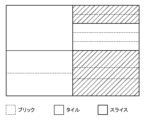
先ず、本実施形態に係る画像符号化装置の機能構成例について、図1のブロック図を用いて説明する。画像分割部102には、符号化対象となる入力画像が入力される。入力画像は動画像を構成する各フレームの画像であっても良いし、静止画像であっても良い。画像分割部102は、入力画像を「一つもしくは複数のタイル」に分割する。タイルは入力画像内の矩形領域を覆う、連続する基本ブロックの集合である。画像分割部102はさらに、それぞれのタイルを一つもしくは複数のブリックに分割する。ブリックは、タイル内の一つもしくは複数の基本ブロックの行(基本ブロック行)で構成される矩形領域(タイル以下の大きさの複数のブロックから成るブロック行を1つ以上含む矩形領域)である。画像分割部102はさらに入力画像を、「一つまたは複数のタイル」あるいは「一つのタイル内の一つ以上のブリック」で構成されるスライスに分割する。スライスは符号化の基本単位であり、スライス毎にスライスの種類を示す情報等のヘッダ情報が付加される。入力画像を4個のタイル、4個のスライス、11個のブリックに分割する例を図7に示す。左上のタイルは1個のブリック、左下のタイルは2個のブリック、右上のタイルは5個のブリック、右下のタイルは3個のブリックにそれぞれ分割されている。そして左のスライスは3個のブリック、右上のスライスは2個のブリック、右中央のスライスは3個のブリック、右下のスライスは3個のブリックを包含するように構成されている。画像分割部102は、このようにして分割したタイル、ブリック、スライスのそれぞれについて、大きさに関する情報を分割情報として出力する。
[First embodiment]
First, an example of the functional configuration of an image encoding apparatus according to this embodiment will be described using the block diagram of FIG. 1. An input image to be encoded is input to the
ブロック分割部103は、画像分割部102から出力された基本ブロック行の画像(基本ブロック行画像)を複数の基本ブロックに分割し、基本ブロック単位の画像(ブロック画像)を後段に出力する。
The block dividing
予測部104は、基本ブロック単位の画像をサブブロックに分割し、サブブロック単位でフレーム内予測であるイントラ予測やフレーム間予測であるインター予測などを行い、予測画像を生成する。ブリックを跨いだイントラ予測(他のブリックのブロックの画素を用いたイントラ予測)、ブリックを跨いだ動きベクトルの予測(他のブリックのブロックの動きベクトルを用いた動きベクトルの予測)は行われない。さらに予測部104は、入力された画像と予測画像から予測誤差を算出して出力する。また予測部104は、予測に必要な情報(予測情報)、例えばサブブロック分割方法、予測モードや動きベクトル等の情報も予測誤差と併せて出力する。
The
変換・量子化部105は、予測誤差をサブブロック単位で直交変換して変換係数を求め、該求めた変換係数を量子化して量子化係数を求める。逆量子化・逆変換部106は、変換・量子化部105から出力された量子化係数を逆量子化して変換係数を再生し、さらに該再生した変換係数を逆直交変換して予測誤差を再生する。
The transform/
フレームメモリ108は、再生された画像を格納しておくメモリとして機能する。画像再生部107は、予測部104から出力された予測情報に基づいてフレームメモリ108を適宜参照して予測画像を生成し、該予測画像と入力された予測誤差から再生画像を生成して出力する。
インループフィルタ部109は、再生画像に対してデブロッキングフィルタやサンプルアダプティブオフセットなどのインループフィルタ処理を行い、該インループフィルタ処理が施された画像(フィルタ画像)を出力する。
The in-
符号化部110は、変換・量子化部105から出力された量子化係数および予測部104から出力された予測情報を符号化することで符号データ(符号化データ)を生成し、該生成した符号データを出力する。
The
統合符号化部111は、画像分割部102から出力された分割情報を用いてヘッダ符号データを生成し、該生成したヘッダ符号データと、符号化部110から出力された符号データと、を含むビットストリームを生成して出力する。制御部199は、画像符号化装置全体の動作制御を行うものであり、上記の画像符号化装置の各機能部の動作制御を行う。
The
次に、図1に示した構成を有する画像符号化装置による入力画像に対する符号化処理について説明する。本実施形態では、説明を容易にするために、イントラ予測符号化の処理のみを説明するが、これに限定されずインター予測符号化の処理においても適用可能である。さらに本実施形態では具体的な説明を行うために、ブロック分割部103は、画像分割部102から出力された基本ブロック行画像を「64×64画素のサイズを有する基本ブロック」を単位に分割するものとして説明する。
Next, encoding processing for an input image by the image encoding apparatus having the configuration shown in FIG. 1 will be described. In this embodiment, in order to simplify the explanation, only intra-prediction encoding processing will be described, but the present invention is not limited to this and can also be applied to inter-prediction encoding processing. Furthermore, in order to provide a specific explanation in this embodiment, the
画像分割部102は入力画像をタイル及びブリックに分割する。画像分割部102による入力画像の分割例を図8に示す。本実施形態では図8(a)に示す如く、1152×1152画素のサイズを有する入力画像を9つのタイル(1つのタイルのサイズは384×384画素)に分割する。各タイルには左上からラスタ順にID(タイルID)が付与され、左上のタイルのタイルIDは0、右下のタイルのタイルIDは8である。
The
また、入力画像におけるタイル、ブリック、スライスの分割例を図8(b)に示す。図8(b)に示す如く、タイルID=0のタイル及びタイルID=7のタイルは2つのブリック(それぞれのブリックのサイズは384×192画素)に分割される。タイルID=2のタイルは2つのブリック(上側のブリックのサイズは384×128画素、下側のブリックのサイズは384×256画素)に分割される。タイルID=3のタイルは3つのブリック(それぞれのブリックのサイズは384×128画素)に分割される。タイルID=1,4,5,6,8のタイルはブリックに分割しておらず(1つのタイルを1つのブリックに分割することに等価)、その結果、タイル=ブリックとなっている。各ブリックにはラスタ順のタイルの中で上から順にIDが付与される。図8(b)に示すBIDがブリックのIDである。また入力画像は、BID=0~2に対応するブリックを含むスライス、BID=3に対応するブリックを含むスライス、BID=4に対応するブリックを含むスライス、BID=5~8及び10~12に対応するブリックを含むスライス、BID=9及び13に対応するブリックを含むスライスに分割される。なお、各スライスにも、ラスタ順のスライスの中で上から順にIDが付与されており、例えばスライス0はID=0のスライス、スライス4はID=4のスライスを指すものとする。
Further, an example of dividing the input image into tiles, bricks, and slices is shown in FIG. 8(b). As shown in FIG. 8B, the tile with tile ID=0 and the tile with tile ID=7 are divided into two bricks (the size of each brick is 384×192 pixels). The tile with tile ID=2 is divided into two bricks (the size of the upper brick is 384×128 pixels, and the size of the lower brick is 384×256 pixels). The tile with tile ID=3 is divided into three bricks (the size of each brick is 384×128 pixels). Tiles with tile ID=1, 4, 5, 6, and 8 are not divided into bricks (equivalent to dividing one tile into one brick), and as a result, the tiles are bricks. IDs are assigned to each brick from the top among the tiles in raster order. The BID shown in FIG. 8(b) is the brick ID. In addition, the input image includes slices including bricks corresponding to BID=0 to 2, slices including bricks corresponding to BID=3, slices including bricks corresponding to BID=4, and slices including bricks corresponding to BID=5 to 8 and 10 to 12. It is divided into slices including the corresponding bricks and slices including the bricks corresponding to BID=9 and 13. Note that each slice is also given an ID in order from the top among the slices in raster order; for example,
そして画像分割部102は、分割したタイル、ブリック、スライスのそれぞれについて、大きさに関する情報を分割情報として統合符号化部111に出力する。また画像分割部102は、各ブリックを基本ブロック行画像に分割し、該分割した基本ブロック行画像をブロック分割部103に出力する。
Then, the
ブロック分割部103は、画像分割部102から出力された基本ブロック行画像を複数の基本ブロックに分割し、基本ブロック単位の画像であるブロック画像(64×64画素)を、後段の予測部104に対して出力する。
The
予測部104は、基本ブロック単位の画像をサブブロックに分割し、サブブロック単位で水平予測や垂直予測などのイントラ予測モードを決定し、該決定したイントラ予測モードおよび符号化済の画素から予測画像を生成する。さらに予測部104は、入力された画像と予測画像から予測誤差を算出し、該算出した予測誤差を変換・量子化部105に対して出力する。また予測部104は、サブブロック分割方法やイントラ予測モードなどの情報を予測情報として、符号化部110および画像再生部107に対して出力する。
The
変換・量子化部105は、予測部104から出力された予測誤差をサブブロック単位で直交変換(サブブロックのサイズに対応した直交変換処理)して変換係数(直交変換係数)を求める。そして変換・量子化部105は、該求めた変換係数を量子化して量子化係数を求める。そして変換・量子化部105は、該求めた量子化係数を符号化部110および逆量子化・逆変換部106に対して出力する。
The transformation/
逆量子化・逆変換部106は、変換・量子化部105から出力された量子化係数を逆量子化して変換係数を再生し、さらに該再生した変換係数を逆直交変換して予測誤差を再生する。そして逆量子化・逆変換部106は、該再生した予測誤差を画像再生部107に対して出力する。
The inverse quantization/
画像再生部107は、予測部104から出力された予測情報に基づいてフレームメモリ108を適宜参照して予測画像を生成し、該予測画像と、逆量子化・逆変換部106から入力された予測誤差と、から再生画像を生成する。そして画像再生部107は、該生成した再生画像をフレームメモリ108に格納する。
The
インループフィルタ部109は、フレームメモリ108から再生画像を読み出し、該読み出した再生画像に対してデブロッキングフィルタやサンプルアダプティブオフセットなどのインループフィルタ処理を行う。そしてインループフィルタ部109は、該インループフィルタ処理が施された画像を再びフレームメモリ108に格納(再格納)する。
The in-
符号化部110は、変換・量子化部105から出力された量子化係数および予測部104から出力された予測情報をエントロピー符号化することで符号データを生成する。エントロピー符号化の方法は特に指定しないが、ゴロム符号化、算術符号化、ハフマン符号化などを用いることができる。そして符号化部110は、該生成した符号データを統合符号化部111に対して出力する。
The
統合符号化部111は、画像分割部102から出力された分割情報を用いてヘッダ符号データを生成し、該生成したヘッダ符号データと、符号化部110から出力された符号データと、を多重化することでビットストリームを生成して出力する。ビットストリームの出力先は特定の出力先に限るものではなく、画像符号化装置の内部若しくは外部のメモリに出力(格納)しても良いし、LANやインターネットなどのネットワークを介して画像符号化装置と通信可能な外部装置に対して送信しても良い。
The
次に、統合符号化部111が出力するビットストリーム(画像符号化装置が符号化するVVCによる符号データ)のフォーマットの一例を図6に示す。図6のビットストリームには、シーケンスの符号化に関わる情報が含まれたヘッダ情報であるシーケンス・パラメータ・セット(SPS)が含まれている。また図6のビットストリームには、ピクチャの符号化に関わる情報が含まれたヘッダ情報であるピクチャ・パラメータ・セット(PPS)が含まれている。また図6のビットストリームには、スライスの符号化に関わる情報が含まれたヘッダ情報であるスライスヘッダ(SLH)が含まれている。また図6のビットストリームには、各ブリック(図6ではブリック0~ブリック(N-1))の符号データが含まれている。
Next, FIG. 6 shows an example of the format of the bit stream (VVC encoded data encoded by the image encoding device) output by the
SPSには画像サイズ情報と基本ブロックデータ分割情報とが含まれている。PPSには、タイルの分割情報であるタイルデータ分割情報と、ブリックの分割情報であるブリックデータ分割情報と、スライスの分割情報であるスライスデータ分割情報0と、基本ブロック行データ同期化情報と、が含まれている。SLHには、スライスデータ分割情報1と基本ブロック行データ位置情報とが含まれている。
The SPS includes image size information and basic block data division information. The PPS includes tile data division information that is tile division information, brick data division information that is brick division information, slice
先ず、SPSについて説明する。SPSには画像サイズ情報として情報601であるpic_width_in_luma_samples及び情報602であるpic_height_in_luma_samplesが含まれている。pic_width_in_luma_samplesは入力画像の水平方向のサイズ(画素数)を表しており、pic_height_in_luma_samplesは入力画像の垂直方向のサイズ(画素数)を表している。本実施形態では、入力画像として図8の入力画像を用いるため、pic_width_in_luma_samples=1152、pic_height_in_luma_samples=1152となる。またSPSには基本ブロックデータ分割情報として情報603であるlog2_ctu_size_minus2が含まれている。log2_ctu_size_minus2は、基本ブロックのサイズを表す。基本ブロックの垂直方向及び水平方向の画素数は1<<(log2_ctu_size_minus2+2)で示される。本実施形態では基本ブロックのサイズは64×64画素であるため、log2_ctu_size_minus2の値は4となる。
First, SPS will be explained. The SPS includes
次に、PPSについて説明する。PPSにはタイルデータ分割情報として情報604~607が含まれている。情報604は、入力画像が複数のタイルに分割されて符号化されているか否かを示すsingle_tile_in_pic_flagである。single_tile_in_pic_flag=1の場合は、入力画像が複数のタイルに分割されて符号化されていないことを示す。一方、single_tile_in_pic_flag=0の場合は、入力画像が複数のタイルに分割されて符号化されていることを示す。
Next, PPS will be explained. The PPS includes
情報605は、single_tile_in_pic_flag=0の場合にタイルデータ分割情報に含められる情報である。情報605は、各タイルが同一のサイズを持つか否かを示すuniform_tile_spacing_flagである。uniform_tile_spacing_flag=1の場合は、各タイルが同一のサイズを持つことを示し、uniform_tile_spacing_flag=0の場合は、サイズが同一ではないタイルが存在することを示す。
情報606および情報607は、uniform_tile_spacing_flag=1の場合にタイルデータ分割情報に含められる情報である。情報606は、(タイルの水平方向の基本ブロック数-1)を示すtile_cols_width_minus1である。情報607は、(タイルの垂直方向の基本ブロック数-1)を示すtile_rows_height_minus1である。入力画像の水平方向のタイル数は、入力画像の水平方向の基本ブロック数をタイルの水平方向の基本ブロック数で除算した場合の商として得られる。この除算により余りが生じた場合は、商に1を加えた数を「入力画像の水平方向のタイル数」とする。また入力画像の垂直方向のタイル数は、入力画像の垂直方向の基本ブロック数をタイルの垂直方向の基本ブロック数で除算した場合の商として得られる。この除算により余りが生じた場合は、商に1を加えた数を「入力画像の垂直方向のタイル数」とする。また、入力画像内の総タイル数は、入力画像の水平方向のタイル数×入力画像の垂直方向のタイル数を計算することで求めることができる。
なお、uniform_tile_spacing_flag=0の場合、他とサイズの異なるタイルが含まれているため、入力画像の水平方向におけるタイルの数、入力画像の垂直方向におけるタイルの数、各タイルの縦横のサイズ、を符号にする。 Note that if uniform_tile_spacing_flag=0, since tiles with different sizes are included, the number of tiles in the horizontal direction of the input image, the number of tiles in the vertical direction of the input image, and the vertical and horizontal size of each tile are coded. Make it.
またPPSにはブリックデータ分割情報として情報608~613が含まれている。情報608は、brick_splitting_present_flagである。brick_splitting_present_flag=1の場合は、入力画像内における1つ以上のタイルが複数のブリックに分割されていることを示す。一方、brick_splitting_present_flag=0の場合は、入力画像内におけるそれぞれのタイルが単一のブリックで構成されていることを示す。
The PPS also includes
情報609は、brick_splitting_present_flag=1の場合にブリックデータ分割情報に含められる情報である。情報609は、それぞれのタイルについて、該タイルが複数のブリックに分割されているか否かを示すbrick_split_flag[]である。i番目のタイルが複数のブリックに分割されているかを示すbrick_split_flag[]をbrick_split_flag[i]と表記する。brick_split_flag[i]=1の場合、i番目のタイルが複数のブリックに分割されていることを示し、brick_split_flag[i]=0の場合、i番目のタイルが単一のブリックで構成されていることを示す。
情報610は、brick_split_flag[i]=1の場合に、i番目のタイルを構成するそれぞれのブリックのサイズが同一であるか否かを示すuniform_brick_spacing_flag[i]である。全てのiについてbrick_split_flag[i]=0であれば、情報610はブリックデータ分割情報には含まれていない。情報610は、brick_split_flag[i]=1を満たすiについて、uniform_brick_spacing_flag[i]を含む。uniform_brick_spacing_flag[i]=1の場合は、i番目のタイルを構成するそれぞれのブリックのサイズが同一であることを示す。一方、uniform_brick_spacing_flag[i]=0の場合は、i番目のタイルを構成するブリックのうち他とサイズが異なるブリックが存在することを示す。
The
情報611は、uniform_brick_spacing_flag[i]=1の場合にブリックデータ分割情報に含められる情報である。情報611は、(i番目のタイルにおけるブリックの垂直方向の基本ブロック数-1)を示すbrick_height_minus1[i]である。
なお、ブリックの垂直方向の基本ブロック数は、該ブリックの垂直方向の画素数を、基本ブロックの垂直方向の画素数(本実施形態では64画素)で除算することで求めることができる。また、タイルを構成するブリック数は、タイルの垂直方向の基本ブロック数をブリックの垂直方向の基本ブロック数で除算した場合の商として得られる。この除算により余りが生じた場合は、商に1を加えた数を「タイルを構成するブリック数」とする。例えばタイルの垂直方向の基本ブロック数が10で、brick_height_minus1の値が2であるとする。このとき、このタイルは上から順に、基本ブロック行数が3のブリック、基本ブロック行数が3のブリック、基本ブロック行数が3のブリック、基本ブロック行数が1のブリック、の4つのブリックに分割されることになる。 Note that the number of basic blocks in the vertical direction of a brick can be determined by dividing the number of pixels in the vertical direction of the brick by the number of pixels in the vertical direction of the basic block (64 pixels in this embodiment). Further, the number of bricks constituting a tile is obtained as the quotient of dividing the number of basic blocks in the vertical direction of the tile by the number of basic blocks in the vertical direction of the bricks. If a remainder is generated as a result of this division, the quotient plus 1 is defined as the "number of bricks constituting the tile." For example, assume that the number of basic blocks in the vertical direction of a tile is 10 and the value of brick_height_minus1 is 2. At this time, this tile consists of four bricks, starting from the top: a brick with 3 basic block rows, a brick with 3 basic block rows, a brick with 3 basic block rows, and a brick with 1 basic block row. It will be divided into
情報612は、uniform_brick_spacing_flag[i]=0を満たすiについて(i番目のタイルを構成するブリック数-1)を示すnum_brick_rows_minus1[i]である。
The
なお、本実施形態では、uniform_brick_spacing_flag[i]=0の場合は、(i番目のタイルを構成するブリック数-1)を示すnum_brick_rows_minus1[i]をブリックデータ分割情報に含めた。しかし、これに限定されるものではない。 In this embodiment, when uniform_brick_spacing_flag[i]=0, num_brick_rows_minus1[i] indicating (the number of bricks constituting the i-th tile - 1) is included in the brick data division information. However, it is not limited to this.
例えばbrick_split_flag[i]=1の時点でi番目のタイルを構成するブリックの数が2以上であると想定する。そして、(該タイルを構成するブリックの数-2)を示すnum_brick_rows_minus2[i]をnum_brick_rows_minus1[i]の代わりに符号化しても良い。このようにすることで、該タイルを構成するブリックの数を示すシンタクスのビット数を減らすことができる。例えば、該タイルが2個のブリックにより構成され、num_brick_rows_minus1[i]をゴロム符号化する場合、「1」を示す「010」の3ビットのデータが符号化される。一方で、(該タイルを構成するブリックの数-2)を示すnum_brick_rows_minus2[i]をゴロム符号化する場合、0を示す「0」の1ビットのデータが符号化される。 For example, assume that the number of bricks forming the i-th tile is 2 or more when brick_split_flag[i]=1. Then, num_brick_rows_minus2[i] indicating (the number of bricks constituting the tile - 2) may be encoded instead of num_brick_rows_minus1[i]. By doing so, it is possible to reduce the number of bits of the syntax indicating the number of bricks constituting the tile. For example, when the tile is composed of two bricks and num_brick_rows_minus1[i] is Golomb encoded, 3-bit data of "010" indicating "1" is encoded. On the other hand, when num_brick_rows_minus2[i] indicating (the number of bricks constituting the tile - 2) is subjected to Golomb encoding, 1-bit data of "0" indicating 0 is encoded.
情報613はuniform_brick_spacing_flag[i]=0を満たすiについて(i番目のタイルにおけるj番目のブリックの垂直方向の基本ブロック数-1)を示すbrick_row_height_minus1[i][j]である。brick_row_height_minus1[i][j]はnum_brick_rows_minus1[i]の数だけ符号化される。なお、上述のnum_brick_rows_minus2[i]を用いた場合は、brick_row_height_minus1[i][j]はnum_brick_rows_minus2[i]+1の数だけ符号化される。タイルにおける下端のブリックの垂直方向の基本ブロック数は、該タイルの垂直方向の基本ブロック数から「brick_row_height_minus1+1」の総和を減算することで求めることができる。例えば、タイルの垂直方向の基本ブロック数=10、num_brick_rows_minus1=3、brick_row_height_minus1=2、1、2であるとする。このとき、該タイルにおける下端のブリックの垂直方向の基本ブロック数は10-(3+2+3)=2になる。
またPPSにはスライスデータ分割情報0として情報614~618が含まれている。情報614は、single_brick_per_slice_flagである。single_brick_per_slice_flag=1の場合、入力画像内の全てのスライスが単一のブリックで構成されていることを示す。一方、single_brick_per_slice_flag=0の場合、入力画像において1つ以上のスライスが複数のブリックで構成されていることを示す。つまり、それぞれのスライスが1つだけのブリックで構成されることを示す。
The PPS also includes
情報615はrect_slice_flagであり、single_brick_per_slice_flag=0の場合にスライスデータ分割情報0に含められる情報である。rect_slice_flagは、スライスが含むタイルがラスタ順か矩形かを示す。図9(a)は、rect_slice_flag=0の場合におけるタイルとスライスとの関係を示しており、スライス内のタイルがラスタ順で符号化されることを示している。一方、図9(b)は、rect_slice_flag=1の場合におけるタイルとスライスとの関係を示しており、スライス内の複数のタイルが矩形状であることを示している。
情報616はnum_slices_in_pic_minus1であり、rect_slice_flag=1かつsingle_brick_per_slice_flag=0の場合にスライスデータ分割情報0に含められる情報である。num_slices_in_pic_minus1は、(入力画像におけるスライスの数-1)を示す。
情報617は、入力画像におけるそれぞれのスライスについて、該スライス(i番目のスライス)の左上のブリックのインデックスを示すtop_left_brick_idx[i]である。
The
情報618は、入力画像中i番目のスライスにおける左上のブリックのインデックスと右下のブリックのインデックスとの差分を示すbottom_right_brick_idx_delta[i]である。ここで、「入力画像中i番目のスライスにおける左上のブリック」とは、該スライスにおいて最初に処理されるブリックである。また、「入力画像中i番目のスライスにおける右下のブリック」とは、該スライスにおいて最後に処理されるブリックである。
ここで、iの範囲は0~num_slices_in_pic_minus1である。ただし、フレーム内の最初のスライスの左上のブリックのインデックスは0と決まっているため、最初のスライスのtop_left_brick_idx[0]は符号化されない。本実施形態では、top_left_brick_idx[i]及びbottom_right_brick_idx_delta[i]のiの範囲を0~num_slices_in_pic_minus1としたが、これに限定されない。例えば、最後のスライス(num_slices_in_pic_minus1番目のスライス)の右下のブリックは、最大のBIDを持つブリックと決まっている。そのため、bottom_right_brick_idx_delta[num_slices_in_pic_minus1]は符号化しなくてもよい。更に、最後のスライス以外のスライスのtop_left_brick_idx[i]及びbottom_right_brick_idx_delta[i]より、最後のスライス以外のスライスが含むブリックは既に特定されている。従って、最後のスライスが含むブリックは、それ以前のスライスに含まれていない全てのブリックと特定することができる。その場合、最後のスライスの左上のブリックは、残されたブリックの中で一番小さいBIDを持つブリックと特定することができる。そのため、top_left_brick_idx[num_slices_in_pic_minus1]も符号化しなくてもよい。そうすることで、ヘッダのビット量をより減らすことができる。 Here, the range of i is 0 to num_slices_in_pic_minus1. However, since the index of the top left brick of the first slice in the frame is determined to be 0, top_left_brick_idx[0] of the first slice is not encoded. In the present embodiment, the range of i in top_left_brick_idx[i] and bottom_right_brick_idx_delta[i] is set to 0 to num_slices_in_pic_minus1, but is not limited thereto. For example, the lower right brick of the last slice (the first slice in num_slices_in_pic_minus) is determined to be the brick with the largest BID. Therefore, bottom_right_brick_idx_delta[num_slices_in_pic_minus1] does not need to be encoded. Furthermore, bricks included in slices other than the last slice have already been identified from top_left_brick_idx[i] and bottom_right_brick_idx_delta[i] of slices other than the last slice. Therefore, the bricks included in the last slice can be identified as all the bricks not included in the previous slices. In that case, the upper left brick of the last slice can be identified as the brick with the smallest BID among the remaining bricks. Therefore, top_left_brick_idx[num_slices_in_pic_minus1] also does not need to be encoded. By doing so, the amount of bits in the header can be further reduced.
またPPSには基本ブロック行データ同期化情報として情報619が符号化されて含まれている。情報619はentropy_coding_sync_enabled_flagである。entropy_coding_sync_enabled_flag=1の場合は、上に隣接する基本ブロック行の所定位置の基本ブロックを処理した時点での発生確率のテーブルを左端のブロックに適用する。これにより、基本ブロック行単位でエントロピー符号化・復号化の並列処理が可能になる。
The PPS also includes encoded
次に、SLHについて説明する。SLHにはスライスデータ分割情報1として情報620~621が符号化されて含まれている。情報620は、rect_slice_flag=1もしくは入力画像中のブリックの数が2以上の場合にスライスデータ分割情報1に含められるslice_addressである。slice_addressは、rect_slice_flag=0の場合はスライスの先頭のBIDを示し、rect_slice_flag=1の場合は、現在のスライスの番号を示す。
Next, SLH will be explained. The SLH includes encoded
情報621は、rect_slice_flag=0かつsingle_brick_per_slice_flag=0の場合にスライスデータ分割情報1に含められるnum_bricks_in_slice_minus1である。num_bricks_in_slice_minus1は(スライス中のブリック数-1)を示す。
SLHには基本ブロック行データ位置情報として情報622が含まれている。情報622はentry_point_offset_minus1[]である。entry_point_offset_minus1[]は、entropy_coding_sync_enabled_flag=1の場合に、(スライス中の基本ブロック行数-1)の数だけ基本ブロック行データ位置情報に符号化されて含められる。
The SLH includes
entry_point_offset_minus1[]は、基本ブロック行の符号データのエントリポイント、即ち基本ブロック行の符号データの先頭位置を表す。entry_point_offset_minus1[j-1]はj番目の基本ブロック行の符号データのエントリポイントを示す。0番目の基本ブロック行の符号データの先頭位置は、該基本ブロック行が属するスライスの符号データの先頭位置と同じであるため省略される。そして、{(j-1)番目の基本ブロック行の符号データの大きさ-1}がentry_point_offset_minus1[j-1]として符号化される。 entry_point_offset_minus1[] represents the entry point of the code data in the basic block row, that is, the starting position of the code data in the basic block row. entry_point_offset_minus1[j-1] indicates the entry point of the code data of the j-th basic block row. The starting position of the code data of the 0th basic block row is omitted because it is the same as the starting position of the code data of the slice to which the basic block row belongs. Then, {the size of code data of the (j-1)th basic block row -1} is encoded as entry_point_offset_minus1[j-1].
次に、本実施形態に画像符号化装置による入力画像の符号化処理(図6の構成を有するビットストリームの生成処理)について、図3のフローチャートに従って説明する。 Next, the input image encoding process (bitstream generation process having the configuration shown in FIG. 6) by the image encoding apparatus of this embodiment will be explained according to the flowchart of FIG.
まず、ステップS301では、画像分割部102は入力画像をタイル、ブリック、スライスに分割する。そして画像分割部102は、分割したタイル、ブリック、スライスのそれぞれについて、大きさに関する情報を分割情報として統合符号化部111に出力する。また画像分割部102は、各ブリックを基本ブロック行画像に分割し、該分割した基本ブロック行画像をブロック分割部103に出力する。
First, in step S301, the
ステップS302では、ブロック分割部103は、基本ブロック行画像を複数の基本ブロックに分割し、基本ブロック単位の画像であるブロック画像を、後段の予測部104に対して出力する。
In step S302, the
ステップS303では、予測部104は、ブロック分割部103から出力された基本ブロック単位の画像をサブブロックに分割し、サブブロック単位でイントラ予測モードを決定し、該決定したイントラ予測モードおよび符号化済の画素から予測画像を生成する。さらに予測部104は、入力された画像と予測画像から予測誤差を算出し、該算出した予測誤差を変換・量子化部105に対して出力する。また予測部104は、サブブロック分割方法やイントラ予測モードなどの情報を予測情報として、符号化部110および画像再生部107に対して出力する。
In step S303, the
ステップS304では、変換・量子化部105は、予測部104から出力された予測誤差をサブブロック単位で直交変換して変換係数(直交変換係数)を求める。そして変換・量子化部105は、該求めた変換係数を量子化して量子化係数を求める。そして変換・量子化部105は、該求めた量子化係数を符号化部110および逆量子化・逆変換部106に対して出力する。
In step S304, the transformation/
ステップS305では、逆量子化・逆変換部106は、変換・量子化部105から出力された量子化係数を逆量子化して変換係数を再生し、さらに該再生した変換係数を逆直交変換して予測誤差を再生する。そして逆量子化・逆変換部106は、該再生した予測誤差を画像再生部107に対して出力する。
In step S305, the inverse quantization/
ステップS306では、画像再生部107は、予測部104から出力された予測情報に基づいてフレームメモリ108を適宜参照して予測画像を生成し、該予測画像と、逆量子化・逆変換部106から入力された予測誤差と、から再生画像を生成する。そして画像再生部107は、該生成した再生画像をフレームメモリ108に格納する。
In step S306, the
ステップS307では、符号化部110は、変換・量子化部105から出力された量子化係数および予測部104から出力された予測情報をエントロピー符号化することで符号データを生成する。
In step S307, the
ここで、entropy_coding_sync_enabled_flag=1の場合、上に隣接する基本ブロック行の所定の位置の基本ブロックを処理した時点での発生確率テーブルを、次の基本ブロック行の左端の基本ブロックを処理する前に適用する。本実施形態では、entropy_coding_sync_enabled_flag=1であるものとして説明する。 Here, if entropy_coding_sync_enabled_flag = 1, the occurrence probability table at the time when the basic block at a predetermined position in the upper adjacent basic block row is processed is applied before processing the leftmost basic block in the next basic block row. do. In this embodiment, the description will be made assuming that entropy_coding_sync_enabled_flag=1.
ステップS308では、制御部199は、スライス内の全ての基本ブロックの符号化が完了したか否かを判断する。この判断の結果、スライス内の全ての基本ブロックの符号化が完了した場合には、処理はステップS309に進む。一方、スライス内の基本ブロックのうちまだ符号化していない基本ブロック(未符号化の基本ブロック)が残っている場合には、該未符号化の基本ブロックを符号化するべく、処理はステップS303に進む。
In step S308, the
ステップS309では、統合符号化部111は、画像分割部102から出力された分割情報を用いてヘッダ符号データを生成し、該生成したヘッダ符号データと、符号化部110から出力された符号データと、を含むビットストリームを生成して出力する。
In step S309, the
入力画像を図8に示す如く分割した場合、タイルデータ分割情報の、single_tile_in_pic_flagは0、uniform_tile_spacing_flagは1になる。またtile_cols_width_minus1は5、tile_rows_height_minus1は5である。 When the input image is divided as shown in FIG. 8, the single_tile_in_pic_flag of the tile data division information becomes 0 and the uniform_tile_spacing_flag becomes 1. Further, tile_cols_width_minus1 is 5, and tile_rows_height_minus1 is 5.
ブリックデータ分割情報のbrick_splitting_present_flagは1である。また、タイルID=1,4,5,6,8に対応するタイルはブリックに分割されていない。然るにbrick_split_flag[1]、brick_split_flag[4]、brick_split_flag[5]、brick_split_flag[6]、brick_split_flag[8]は0である。またタイルID=0,2,3,7に対応するタイルはブリックに分割されている。然るにbrick_split_flag[0]、brick_split_flag[2]、brick_split_flag[3]、brick_split_flag[7]は1である。 brick_splitting_present_flag of the brick data splitting information is 1. Further, tiles corresponding to tile ID=1, 4, 5, 6, and 8 are not divided into bricks. However, brick_split_flag[1], brick_split_flag[4], brick_split_flag[5], brick_split_flag[6], and brick_split_flag[8] are 0. Furthermore, tiles corresponding to tile ID=0, 2, 3, and 7 are divided into bricks. However, brick_split_flag[0], brick_split_flag[2], brick_split_flag[3], and brick_split_flag[7] are 1.
また、タイルID=0,3,7に対応するタイルは何れも同一サイズのブリックに分割されている。然るにuniform_brick_spacing_flag[0]、uniform_brick_spacing_flag[3]、uniform_brick_spacing_flag[7]は何れも1である。タイルID=2に対応するタイルについては、BID=3のブリックのサイズは、BID=4のブリックのサイズとは異なる。然るに、uniform_brick_spacing_flag[2]は0である。 Furthermore, the tiles corresponding to tile ID=0, 3, and 7 are all divided into bricks of the same size. However, uniform_brick_spacing_flag[0], uniform_brick_spacing_flag[3], and uniform_brick_spacing_flag[7] are all 1. For the tile corresponding to tile ID=2, the size of the brick with BID=3 is different from the size of the brick with BID=4. However, uniform_brick_spacing_flag[2] is 0.
brick_height_minus1[0]は2であり、brick_height_minus1[3]は1である。また、brick_height_minus1[7]は2である。なお、brick_height_minus1はuniform_brick_spacingが1の場合に符号化される。 brick_height_minus1[0] is 2 and brick_height_minus1[3] is 1. Further, brick_height_minus1[7] is 2. Note that brick_height_minus1 is encoded when uniform_brick_spacing is 1.
brick_row_height_minus1[2][0]は1である。なお、num_brick_rows_minus1[2]ではなく、代わりに上述のnum_brick_rows_minus2[2]のシンタクスを符号化する場合は、値は0になる。 brick_row_height_minus1[2][0] is 1. Note that when encoding the syntax of num_brick_rows_minus2[2] described above instead of num_brick_rows_minus1[2], the value becomes 0.
また、本実施形態では、1つのスライスが複数のブリックを含むため、スライスデータ分割情報0におけるsingle_brick_per_slice_flagは0となる。また本実施形態では、スライスが複数のタイルを矩形で内包するため、rect_slice_flagは1である。図8(b)に示す如く、入力画像におけるスライスの数は5であるため、num_slices_in_pic_minus1は4になる。
Furthermore, in this embodiment, since one slice includes a plurality of bricks, single_brick_per_slice_flag in slice
スライス0のtop_left_brick_idx[0]は0が自明であるため符号化されず、bottom_right_brick_idx_delta[0]は2(=2-0)である。スライス1のtop_left_brick_idx[1]は3であり、bottom_right_brick_idx_delta[1]は0(=3-3)である。スライス2のtop_left_brick_idx[2]は4であり、bottom_right_brick_idx_delta[2]は0(=4-4)である。スライス3のtop_left_brick_idx[3]は5であり、bottom_right_brick_idx_delta[3]は7(=12-5)である。スライス4のtop_left_brick_idx[4]は9であり、bottom_right_brick_idx_delta[4]は4(=13-9)である。なお、上述のように、top_left_brick_idx[4]、bottom_right_brick_idx_delta[4]は符号化しなくてもよい。
Top_left_brick_idx[0] of
また、entry_point_offset_minus1[]については、符号化部110より送られた(スライス中の(j-1)番目の基本ブロック行の符号データの大きさ-1)をentry_point_offset_minus1[j-1]として符号化する。スライス中のentry_point_offset_minus1[]の数は、(スライス中の基本ブロック行数-1)と等しい。本実施形態では、bottom_right_brick_idx_delta[0]は2であることからスライス0はBID=0~2のブリックからなることがわかる。
For entry_point_offset_minus1[], the code data size of the (j-1)th basic block row in the slice - 1 sent from the
ここで、brick_height_minus1[0]は2、tile_rows_height_minus1は5である。これにより、BID=0に対応するブリックの基本ブロック行の数およびBID=1に対応するブリックの基本ブロック行の数は何れも、brick_height_minus1[0]+1=3となる。またBID=2に対応するブリックの基本ブロック行の数はtile_rows_height_minus1+1=6となる。よってスライス0の基本ブロック行数は3+3+6=12である。よってjの範囲は0~10となる。
Here, brick_height_minus1[0] is 2 and tile_rows_height_minus1 is 5. As a result, the number of basic block rows of the brick corresponding to BID=0 and the number of basic block rows of the brick corresponding to BID=1 are both brick_height_minus1[0]+1=3. Further, the number of basic block rows of the brick corresponding to BID=2 is tile_rows_height_minus1+1=6. Therefore, the number of basic block rows in
スライス1については、top_left_brick_idx[1]は3、bottom_right_brick_idx_delta[1]は0であることから、BID=3のブリックからなることがわかる。また、brick_row_height_minus1[2][0]が1であることから、スライス1(BID=3のブリック)の基本ブロック行数は2である。よってjの範囲は0のみとなる。
Regarding
スライス2については、top_left_brick_idx[2]が4、bottom_right_brick_idx_delta[2]が0であることから、BID=4のブリックからなることがわかる。また、brick_row_height_minus1[2][0]が1であり、num_brick_rows_minus1[2]が1、tile_rows_height_minus1が5である。これにより、スライス2(BID=4のブリック)の基本ブロック行数は、{(tile_rows_height_minus1+1)-(brick_row_height_minus1[2][0]+1)}=4である。よってjの範囲は0~2となる。
Regarding
スライス3はBID=5~8、10~12のブリックから構成される。tile_rows_height_minus1が5であることから、BID=8及び10のブリックの基本ブロック行数は6(=tile_rows_height_minus1+1)であることがわかる。また、brick_height_minus1[3]が1であることから、BID=5~7のブリックの基本ブロック行数は2(=brick_height_minus1[3]+1)であることがわかる。また、brick_height_minus1[7]が2であることから、BID=11及び12のブリックの基本ブロック行数は3(=brick_height_minus1[7]+1)であることがわかる。よって、スライス3を構成している全てのブリックの基本ブロック行数の合計は、2+2+2+6+6+3+3=24であることがわかる。よってjの範囲は0~22となる。
スライス4はBID=9のブリック及びBID=13のブリックから構成される。tile_rows_height_minus1が5であることから、BID=9のブリック及びBID=13のブリックのそれぞれの基本ブロック行数は6(=tile_rows_height_minus1+1)である。よって、スライス4を構成している全てのブリックの基本ブロック行数の合計は、6+6=12であることがわかる。よってjの範囲は0~10になる。
このような処理により、各スライスにおける基本ブロック行数が確定する。本実施形態では、他のシンタクスからentry_point_offset_minus1の数を導出することができるので、従来のようにnum_entry_point_offsetを符号化してヘッダに含める必要はない。よって、本実施形態によれば、ビットストリームのデータ量を削減することができる。 Through such processing, the number of basic block rows in each slice is determined. In this embodiment, the number of entry_point_offset_minus1 can be derived from other syntax, so there is no need to encode num_entry_point_offset and include it in the header as in the conventional case. Therefore, according to this embodiment, the data amount of the bitstream can be reduced.
ステップS310では、制御部199は、入力画像における全ての基本ブロックの符号化が完了したか否かを判断する。この判断の結果、入力画像における全ての基本ブロックの符号化が完了した場合には、処理はステップS311に進む。一方、入力画像において未だ符号化されていない基本ブロックが残っている場合には、処理はステップS303に進み、未だ符号化されていない基本ブロックについて以降の処理を行う。
In step S310, the
ステップS311では、インループフィルタ部109は、ステップS306で生成された再生画像に対してインループフィルタ処理を行い、該インループフィルタ処理が施された画像を出力する。
In step S311, the in-
このように本実施形態によれば、ブリックが有する基本ブロック行の符号データの先頭位置を示す情報がいくつ符号化されているのかを示す情報を符号化してビットストリームに含めなくても良く、該情報が導出可能なビットストリームを生成することができる。 As described above, according to the present embodiment, it is not necessary to encode and include in the bitstream information indicating how many pieces of information indicating the start position of code data of a basic block row included in a brick are encoded. A bitstream can be generated from which information can be derived.
[第2の実施形態]
本実施形態では、第1の実施形態に係る画像符号化装置によって生成されたビットストリームを復号する画像復号装置について説明する。なお、ビットストリームの構成など、第1の実施形態と共通する要件については第1の実施形態にて説明したとおりであるため、説明は省略する。
[Second embodiment]
In this embodiment, an image decoding device that decodes a bitstream generated by the image encoding device according to the first embodiment will be described. Note that the requirements common to the first embodiment, such as the configuration of the bitstream, are the same as described in the first embodiment, so the description thereof will be omitted.
本実施形態に係る画像復号装置の機能構成例について、図2のブロック図を用いて説明する。分離復号部202は、第1の実施形態に係る画像符号化装置によって生成されたビットストリームを取得する。ビットストリームの取得方法は特定の取得方法に限らない。例えば、LANやインターネットなどのネットワークを介して画像符号化装置から直接的もしくは間接的にビットストリームを取得しても良いし、画像復号装置の内部もしくは外部に保存しておいたビットストリームを取得しても良い。そして分離復号部202は、該取得したビットストリームから、復号処理に関する情報や係数に関する符号データを分離し、復号部203へ送る。また分離復号部202は、ビットストリームのヘッダの符号データを復号する。本実施形態では、タイル、ブリック、スライス、基本ブロックの大きさ等の画像の分割に関するヘッダ情報を復号して分割情報を生成し、該生成した分割情報を画像再生部205に出力する。つまり分離復号部202は、図1の統合符号化部111と逆の動作を行う。
An example of the functional configuration of the image decoding device according to this embodiment will be described using the block diagram of FIG. 2. The
復号部203は、分離復号部202から出力された符号データを復号して量子化係数および予測情報を再生する。逆量子化・逆変換部204は、量子化係数に対して逆量子化を行って変換係数を生成し、該生成した変換係数に対して逆直交変換を行うことで予測誤差を再生する。
Decoding
フレームメモリ206は、再生されたピクチャの画像データを格納するためのメモリである。画像再生部205は、入力された予測情報に基づいてフレームメモリ206を適宜参照して予測画像を生成する。そして画像再生部205は、該生成した予測画像と逆量子化・逆変換部204で再生された予測誤差から再生画像を生成する。そして画像再生部205は、再生画像について、分離復号部202から入力された分割情報に基づいてタイル、ブリック、スライスの入力画像中の位置を特定して出力する。
インループフィルタ部207は、上記のインループフィルタ部109と同様、再生画像に対してデブロッキングフィルタなどのインループフィルタ処理を行い、インループフィルタ処理が施された画像を出力する。制御部299は、画像復号装置全体の動作制御を行うものであり、上記の画像復号装置の各機能部の動作制御を行う。
Like the in-
次に、図2に示した構成を有する画像復号装置によるビットストリームの復号処理について説明する。以下では、ビットストリームをフレーム単位で画像復号装置に入力するものとして説明するが、1フレーム分の静止画像のビットストリームを画像復号装置に入力するようにしても良い。また、本実施形態では説明を容易にするために、イントラ予測復号処理のみを説明するが、これに限定されずインター予測復号処理においても適用可能である。 Next, a bitstream decoding process performed by the image decoding apparatus having the configuration shown in FIG. 2 will be described. Although the following explanation assumes that the bitstream is input to the image decoding device in units of frames, it is also possible to input a bitstream of one frame worth of still images to the image decoding device. Further, in this embodiment, in order to simplify the explanation, only intra-prediction decoding processing will be described, but the present invention is not limited to this and can also be applied to inter-prediction decoding processing.
分離復号部202は、入力されたビットストリームから、復号処理に関する情報や係数に関する符号データを分離し、復号部203へ送る。また分離復号部202は、ビットストリームのヘッダの符号データを復号する。より具体的には分離復号部202は、図6における基本ブロックデータ分割情報、タイルデータ分割情報、ブリックデータ分割情報、スライスデータ分割情報0、基本ブロック行データ同期化情報、基本ブロック行データ位置情報等を復号して分割情報を生成する。そして分離復号部202は、該生成した分割情報を画像再生部205に出力する。また分離復号部202は、ピクチャデータの基本ブロック単位の符号データを再生し、復号部203に出力する。
Separation/
復号部203は、分離復号部202から出力された符号データを復号して量子化係数および予測情報を再生する。再生された量子化係数は逆量子化・逆変換部204に出力され、再生された予測情報は画像再生部205に出力される。
Decoding
逆量子化・逆変換部204は、入力された量子化係数に対して逆量子化を行って変換係数を生成し、該生成した変換係数に対して逆直交変換を行うことで予測誤差を再生する。再生された予測誤差は画像再生部205に出力される。
The inverse quantization/
画像再生部205は、分離復号部202から入力された予測情報に基づいてフレームメモリ206を適宜参照して予測画像を生成する。そして画像再生部205は、該生成した予測画像と逆量子化・逆変換部204で再生された予測誤差から再生画像を生成する。そして画像再生部205は、再生画像について、分離復号部202から入力された分割情報に基づいて、例えば図7のようなタイル、ブリック、スライスの形状および入力画像中の位置を特定してフレームメモリ206に出力(格納)する。フレームメモリ206に格納された画像は予測の際の参照に用いられる。
The
インループフィルタ部207は、フレームメモリ206から読み出した再生画像に対してデブロッキングフィルタなどのインループフィルタ処理を行い、インループフィルタ処理が施された画像をフレームメモリ206に出力(格納)する。
The in-
制御部299は、フレームメモリ206に格納された再生画像を出力する。再生画像の出力先は特定の出力先に限らない。例えば制御部299は、画像復号装置が有する表示装置に該再生画像を出力して該表示装置に該再生画像を表示させても良い。また例えば制御部299は、LANやインターネットなどのネットワークを介して再生画像を外部の装置に対して送信しても良い。
The
次に、本実施形態に係る画像復号装置によるビットストリームの復号処理(図6の構成を有するビットストリームの復号処理)について、図4のフローチャートに従って説明する。 Next, the bitstream decoding process (the bitstream decoding process having the configuration shown in FIG. 6) by the image decoding apparatus according to the present embodiment will be described according to the flowchart in FIG. 4.
ステップS401では、分離復号部202は、入力されたビットストリームから、復号処理に関する情報や係数に関する符号データを分離し、復号部203へ送る。また分離復号部202は、ビットストリームのヘッダの符号データを復号する。より具体的には、分離復号部202は、図6における基本ブロックデータ分割情報、タイルデータ分割情報、ブリックデータ分割情報、スライスデータ分割情報、基本ブロック行データ同期化情報、基本ブロック行データ位置情報等を復号して分割情報を生成する。そして分離復号部202は、該生成した分割情報を画像再生部205に出力する。また分離復号部202は、ピクチャデータの基本ブロック単位の符号データを再生し、復号部203に出力する。
In step S401, the separation/
本実施形態では、ビットストリームの符号化元である入力画像の分割は図8に示した分割とする。ビットストリームの符号化元である入力画像やその分割に係る情報は分割情報から導出することができる。 In this embodiment, the input image, which is the source of bitstream encoding, is divided as shown in FIG. 8. Information regarding the input image from which the bitstream is encoded and its division can be derived from the division information.
画像サイズ情報に含まれているpic_width_in_luma_samplesから、入力画像の水平方向のサイズ(横サイズ)が1152画素であることを特定することができる。また、画像サイズ情報に含まれているpic_height_in_luma_samplesから、入力画像の垂直方向のサイズ(縦サイズ)が1152画素であることを特定することができる。 From pic_width_in_luma_samples included in the image size information, it can be specified that the horizontal size (horizontal size) of the input image is 1152 pixels. Further, from pic_height_in_luma_samples included in the image size information, it can be specified that the vertical size (vertical size) of the input image is 1152 pixels.
また、基本ブロックデータ分割情報のlog2_ctu_size_minus2=4であることから、基本ブロックのサイズを、1<<log2_ctu_size_minus2+2より、64×64画素と導出することができる。
Furthermore, since log2_ctu_size_minus2=4 in the basic block data division information, the size of the basic block can be derived as 64×64 pixels from 1<<
また、タイルデータ分割情報のsingle_tile_in_pic_flag=0であることから、入力画像が複数のタイルに分割されていることを特定することができる。そして、uniform_tile_spacing_flag=1であることから、各タイルが(端部を除いて)同一のサイズを有することを特定することができる。 Furthermore, since the tile data division information single_tile_in_pic_flag=0, it can be specified that the input image is divided into a plurality of tiles. Since uniform_tile_spacing_flag=1, it can be specified that each tile has the same size (excluding the edges).
また、tile_cols_width_minus1=5、tile_rows_height_minus1=5であることから、各タイルが6×6個の基本ブロックで構成されていることを特定することができる。つまり、各タイルが384×384画素で構成されていることを特定することができる。入力画像が1152×1152画素であることから、該入力画像は水平方向に3つ、垂直方向に3つの9つのタイルに分割されて符号化されていることがわかる。 Furthermore, since tile_cols_width_minus1=5 and tile_rows_height_minus1=5, it can be specified that each tile is composed of 6×6 basic blocks. In other words, it can be specified that each tile is composed of 384×384 pixels. Since the input image has 1152×1152 pixels, it can be seen that the input image is divided and encoded into nine tiles, three in the horizontal direction and three in the vertical direction.
また、ブリックデータ分割情報のbrick_splitting_present_flag=1であることから、入力画像中の少なくとも一つのタイルが複数のブリックに分割されていることを特定することができる。 Furthermore, since brick_splitting_present_flag=1 in the brick data division information, it can be specified that at least one tile in the input image is divided into a plurality of bricks.
また、brick_split_flag[1]、brick_split_flag[4]、brick_split_flag[5]、brick_split_flag[6]、brick_split_flag[8]は0である。これにより、タイルID=1,4,5,6,8に対応するタイルはブリックに分割されていないことを特定することができる。本実施形態では、すべてのタイルの基本ブロック行数が6であることから、タイルID=1、4、5、6、8に対応するタイルのブリックの基本ブロック行数は6であることがわかる。 Further, brick_split_flag[1], brick_split_flag[4], brick_split_flag[5], brick_split_flag[6], and brick_split_flag[8] are 0. This makes it possible to specify that the tiles corresponding to tile ID=1, 4, 5, 6, and 8 are not divided into bricks. In this embodiment, since the number of basic block rows of all tiles is 6, it can be seen that the number of basic block rows of bricks of tiles corresponding to tile ID = 1, 4, 5, 6, and 8 is 6. .
一方で、brick_split_flag[0]、brick_split_flag[2]、brick_split_flag[3]、brick_split_flag[7]は1である。これにより、タイルID=0,2,3,7に対応するタイルはブリックに分割されていることを特定することができる。また、uniform_brick_spacing_flag[0]、uniform_brick_spacing_flag[3]、uniform_brick_spacing_flag[7]は何れも1である。これにより、タイルID=0,3,7に対応するタイルは何れも同一サイズのブリックに分割されていることを特定することができる。 On the other hand, brick_split_flag[0], brick_split_flag[2], brick_split_flag[3], and brick_split_flag[7] are 1. This makes it possible to specify that the tiles corresponding to tile ID=0, 2, 3, and 7 are divided into bricks. Furthermore, uniform_brick_spacing_flag[0], uniform_brick_spacing_flag[3], and uniform_brick_spacing_flag[7] are all 1. This makes it possible to specify that the tiles corresponding to tile ID=0, 3, and 7 are all divided into bricks of the same size.
また、brick_height_minus1[0]、brick_height_minus1[7]は何れも2である。然るに、タイルID=0に対応するタイル及びタイルID=7に対応するタイルは何れも、タイル内のブリックの垂直方向の基本ブロック数が3であることを特定することができる。また、タイルID=0に対応するタイル及びタイルID=7に対応するタイルは何れも、該タイル内のブリック数が2(=タイルの基本ブロック行数(6)/タイル内のブリックの垂直方向の基本ブロック数(3))であることを特定することができる。 Further, brick_height_minus1[0] and brick_height_minus1[7] are both 2. However, for both the tile corresponding to tile ID=0 and the tile corresponding to tile ID=7, it can be specified that the number of basic blocks in the vertical direction of the bricks in the tile is three. In addition, for both the tile corresponding to tile ID=0 and the tile corresponding to tile ID=7, the number of bricks in the tile is 2 (=number of basic block rows of the tile (6)/vertical direction of the bricks in the tile. It can be specified that the number of basic blocks is (3 ) .
また、brick_height_minus1[3]は1である。然るに、タイルID=3に対応するタイル内のブリックの垂直方向の基本ブロック数が2であることを特定することができる。また、タイルID=3に対応するタイル内のブリック数が3(=タイルの基本ブロック行数(6)/タイル内のブリックの垂直方向の基本ブロック数(2))であることを特定することができる。 Further, brick_height_minus1[3] is 1. However, it can be determined that the number of basic blocks in the vertical direction of the bricks in the tile corresponding to tile ID=3 is 2. Also, specify that the number of bricks in the tile corresponding to tile ID = 3 is 3 (=number of basic block rows of tile (6)/number of basic blocks in the vertical direction of bricks in tile (2) ) . Can be done.
タイルID=2に対応するタイルについては、num_brick_rows_minus1[2]=1であることから、該タイルは2つのブリックで構成されていることを特定することができる。また、uniform_brick_spacing_flag[2]=0である。これにより、タイルID=2に対応するタイルは、他とサイズが異なるブリックが存在することを特定することができる。そして、brick_row_height_minus1[2][0]=1、brick_row_height_minus1[2][1]=3、全てのタイルの垂直方向の基本ブロック数は6である。これにより、タイルID=2に対応するタイルは上から順に、垂直方向の基本ブロック数が2のブリック、垂直方向の基本ブロック数が4のブリック、で構成されていることを特定することができる。なお、brick_row_height_minus1[2][1]=3は符号化しないようにしてもよい。タイルにおけるブリックの数が2つの場合、タイルの高さと、タイル内の1つ目のブリックの高さ(brick_row_height_minus1[2][0]=1)とから2つ目のブリックの高さを求めることが可能であるためである。 Regarding the tile corresponding to tile ID=2, since num_brick_rows_minus1[2]=1, it can be specified that the tile is composed of two bricks. Further, uniform_brick_spacing_flag[2]=0. This makes it possible to identify that the tile corresponding to tile ID=2 has a brick that is different in size from the others. Then, brick_row_height_minus1[2][0]=1, brick_row_height_minus1[2][1]=3, and the number of basic blocks in the vertical direction of all tiles is 6. As a result, it can be specified that the tile corresponding to tile ID=2 is composed of bricks with the number of basic blocks in the vertical direction of 2 and bricks with the number of basic blocks in the vertical direction of 4, in order from the top. . Note that brick_row_height_minus1[2][1]=3 may not be encoded. If the number of bricks in a tile is two, calculate the height of the second brick from the height of the tile and the height of the first brick in the tile (brick_row_height_minus1[2][0]=1). This is because it is possible.
また、スライスデータ分割情報0におけるsingle_brick_per_slice_flag=0であることから、少なくとも1つのスライスが複数のブリックで構成されていることを特定することができる。本実施形態では、uniform_brick_spacing_flag[i]=0の場合は、(i番目のタイルを構成するブリック数-1)を示すnum_brick_rows_minus1[i]をブリックデータ分割情報に含めた。しかし、これに限定されるものではない。
Furthermore, since single_brick_per_slice_flag=0 in the slice
例えばbrick_split_flag[i]=1の時点でi番目のタイルを構成するブリックの数が2以上であると想定する。そして、(該タイルを構成するブリックの数-2)を示すnum_brick_rows_minus2[i]をnum_brick_rows_minus1[i]の代わりに復号しても良い。このようにすることで、該タイルを構成するブリックの数を示すシンタクスのビット数を減らしたビットストリームを復号することができる。 For example, assume that the number of bricks forming the i-th tile is 2 or more when brick_split_flag[i]=1. Then, num_brick_rows_minus2[i] indicating (the number of bricks constituting the tile - 2) may be decoded instead of num_brick_rows_minus1[i]. By doing so, it is possible to decode a bitstream in which the number of bits of the syntax indicating the number of bricks constituting the tile is reduced.
次に、各ブリックの左上及び右下の境界の座標を求める。座標は入力画像の左上を原点とし、基本ブロックの水平位置と垂直位置で示される。例えば、左から3番目、上から2番目の基本ブロックの左上の境界の座標は(3,2)、右下の境界の座標は(4,3)になる。 Next, find the coordinates of the upper left and lower right boundaries of each brick. The coordinates have the upper left corner of the input image as the origin, and are indicated by the horizontal and vertical positions of the basic blocks. For example, the coordinates of the upper left boundary of the third basic block from the left and the second from the top are (3, 2), and the coordinates of the lower right boundary are (4, 3).
タイルID=0に対応するタイル内のBID=0のブリックの左上の境界の座標は(0,0)である。BID=0のブリックの基本ブロック行数は3で、全てのタイルの水平方向の基本ブロック数は6であるから、右下の境界の座標は(3,3)になる。 The coordinates of the upper left boundary of the brick with BID=0 in the tile corresponding to tile ID=0 are (0,0). The number of basic block rows of a brick with BID=0 is 3, and the number of basic blocks in the horizontal direction of all tiles is 6, so the coordinates of the lower right boundary are (3, 3).
タイルID=0に対応するタイル内のBID=1のブリックの左上の境界の座標は(0,3)である。BID=1のブリックの基本ブロック行数は3で、全てのタイルの水平方向の基本ブロック数は6であるから、右下の境界の座標は(6,6)になる。 The coordinates of the upper left boundary of the brick with BID=1 in the tile corresponding to tile ID=0 are (0,3). The number of basic block rows of a brick with BID=1 is 3, and the number of basic blocks in the horizontal direction of all tiles is 6, so the coordinates of the lower right boundary are (6, 6).
タイルID=1に対応するタイル(BID=2のブリック)の左上の境界の座標は(6,0)である。BID=2のブリックの基本ブロック行数は6で、全てのタイルの水平方向の基本ブロック数は6であるから、右下の境界の座標は(12,6)になる。 The coordinates of the upper left boundary of the tile corresponding to tile ID=1 (brick with BID=2) are (6,0). The number of basic block rows of a brick with BID=2 is 6, and the number of basic blocks in the horizontal direction of all tiles is 6, so the coordinates of the lower right boundary are (12, 6).
タイルID=2に対応するタイル内のBID=3のブリックの左上の境界の座標は(12,0)である。BID=3のブリックの基本ブロック行数は2であるから、右下の境界の座標は(18,2)になる。 The coordinates of the upper left boundary of the brick with BID=3 in the tile corresponding to tile ID=2 are (12,0). Since the number of basic block rows of the brick with BID=3 is 2, the coordinates of the lower right boundary are (18, 2).
タイルID=2に対応するタイル内のBID=4のブリックの左上の境界の座標は(12,2)である。BID=4のブリックの基本ブロック行数は4であるから、右下の境界の座標は(18,6)になる。 The coordinates of the upper left boundary of the brick with BID=4 in the tile corresponding to tile ID=2 are (12,2). Since the number of basic block rows of the brick with BID=4 is 4, the coordinates of the lower right boundary are (18, 6).
タイルID=3に対応するタイル内のBID=5のブリックの左上の境界の座標は(0,6)である。BID=5のブリックの基本ブロック行数は2であるから、右下の境界の座標は(6,8)になる。 The coordinates of the upper left boundary of the brick with BID=5 in the tile corresponding to tile ID=3 are (0,6). Since the number of basic block rows of the brick with BID=5 is 2, the coordinates of the lower right boundary are (6, 8).
タイルID=3に対応するタイル内のBID=6のブリックの左上の境界の座標は(0,8)である。BID=6のブリックの基本ブロック行数は2であるから、右下の境界の座標は(6,10)になる。 The coordinates of the upper left boundary of the brick with BID=6 in the tile corresponding to tile ID=3 are (0,8). Since the number of basic block rows of the brick with BID=6 is 2, the coordinates of the lower right boundary are (6, 10).
タイルID=3に対応するタイル内のBID=7のブリックの左上の境界の座標は(0,10)である。BID=7のブリックの基本ブロック行数は2であるから、右下の境界の座標は(6,12)になる。 The coordinates of the upper left boundary of the brick with BID=7 in the tile corresponding to tile ID=3 are (0,10). Since the number of basic block rows of the brick with BID=7 is 2, the coordinates of the lower right boundary are (6, 12).
タイルID=4に対応するタイル(BID=8のブリック)の左上の境界の座標は(6,6)である。BID=8のブリックの基本ブロック行数は6で、全てのタイルの水平方向の基本ブロック数は6であるから、右下の境界の座標は(12,12)になる。 The coordinates of the upper left boundary of the tile corresponding to tile ID=4 (brick with BID=8) are (6, 6). The number of basic block rows of a brick with BID=8 is 6, and the number of basic blocks in the horizontal direction of all tiles is 6, so the coordinates of the lower right boundary are (12, 12).
タイルID=5に対応するタイル(BID=9のブリック)の左上の境界の座標は(12,6)である。BID=9のブリックの基本ブロック行数は6で、全てのタイルの水平方向の基本ブロック数は6であるから、右下の境界の座標は(18,12)になる。 The coordinates of the upper left boundary of the tile corresponding to tile ID=5 (brick with BID=9) are (12, 6). The number of basic block rows of a brick with BID=9 is 6, and the number of basic blocks in the horizontal direction of all tiles is 6, so the coordinates of the lower right boundary are (18, 12).
タイルID=6に対応するタイル(BID=10のブリック)の左上の境界の座標は(0,12)である。BID=10のブリックの基本ブロック行数は6で、全てのタイルの水平方向の基本ブロック数は6であるから、右下の境界の座標は(6,18)になる。 The coordinates of the upper left boundary of the tile corresponding to tile ID=6 (brick with BID=10) are (0, 12). The number of basic block rows of a brick with BID=10 is 6, and the number of basic blocks in the horizontal direction of all tiles is 6, so the coordinates of the lower right boundary are (6, 18).
タイルID=7に対応するタイル内のBID=11のブリックの左上の境界の座標は(6,12)である。BID=11のブリックの基本ブロック行数は3で、全てのタイルの水平方向の基本ブロック数は6であるから、右下の境界の座標は(12,15)になる。 The coordinates of the upper left boundary of the brick with BID=11 in the tile corresponding to tile ID=7 are (6,12). The number of basic block rows of a brick with BID=11 is 3, and the number of basic blocks in the horizontal direction of all tiles is 6, so the coordinates of the lower right boundary are (12, 15).
タイルID=7に対応するタイル内のBID=12のブリックの左上の境界の座標は(6,15)である。BID=12のブリックの基本ブロック行数は3で、全てのタイルの水平方向の基本ブロック数は6であるから、右下の境界の座標は(12,18)になる。 The coordinates of the upper left boundary of the brick with BID=12 in the tile corresponding to tile ID=7 are (6, 15). The number of basic block rows of a brick with BID=12 is 3, and the number of basic blocks in the horizontal direction of all tiles is 6, so the coordinates of the lower right boundary are (12, 18).
タイルID=8に対応するタイル(BID=13のブリック)の左上の境界の座標は(12,12)である。BID=13のブリックの基本ブロック行数は6で、全てのタイルの水平方向の基本ブロック数は6であるから、右下の境界の座標は(18,18)になる。 The coordinates of the upper left boundary of the tile corresponding to tile ID=8 (brick with BID=13) are (12, 12). The number of basic block rows of a brick with BID=13 is 6, and the number of basic blocks in the horizontal direction of all tiles is 6, so the coordinates of the lower right boundary are (18, 18).
次に、各スライスに含まれるブリックを特定する。num_slices_in_pic_minus1=4であるため、入力画像におけるスライスの数が5であることを特定することができる。また、処理対象のスライスのslice_addressから対応するブリックが特定可能である。すなわち、slice_addressがNの場合は処理対象のスライスがスライスNであることがわかる。 Next, identify the bricks included in each slice. Since num_slices_in_pic_minus1=4, it can be specified that the number of slices in the input image is 5. Further, the corresponding brick can be specified from the slice_address of the slice to be processed. That is, if slice_address is N, it can be seen that the slice to be processed is slice N.
スライス0の場合、bottom_right_brick_idx_delta[0]が2である。これにより、スライス0に含まれるブリックは、BID=0のブリックの左上の境界の座標とBID=2のブリックの右下の境界の座標に囲まれた長方形の領域に含まれるブリックであることを特定することができる。BID=0のブリックの左上の境界の座標は(0,0)、BID=2のブリックの右下の境界は(12,6)であるため、スライス0に含まれるブリックはBID=0~2のブリックであることを特定することができる。
For
スライス1の場合、top_left_brick_idx[1]が3、bottom_right_brick_idx_delta[1]が0であるため、スライス1に含まれるブリックはBID=3のブリックであることを特定することができる。
In the case of
スライス2の場合、top_left_brick_idx[2]が4、bottom_right_brick_idx_delta[2]が0であるため、スライス2に含まれるブリックはBID=4のブリックであることを特定することができる。
In the case of
スライス3の場合、top_left_brick_idx[3]が5、bottom_right_brick_idx_delta[3]が7である。BID=5のブリックの左上の境界の座標が(0,6)、BID=12のブリックの右下の境界の座標が(12,18)であることから、左上座標を(0,6)、右下座標を(12,18)とする領域に含まれるブリックがスライス3に含まれるものと特定できる。その結果、BID=5~8および10~12に対応するブリックがスライス3に含まれるブリックであることを特定することができる。BID=9に対応するブリックの右下の境界の座標は(18,12)、BID=13に対応するブリックの右下の境界の座標は(18,18)であり、何れもスライス3の範囲から外れているため、スライス3に属さないと判断される。
For
スライス4の場合、top_left_brick_idx[4]が9、bottom_right_brick_idx_delta[4]が4である。BID=9のブリックの左上の境界の座標が(12,6)、BID=13のブリックの右下の境界の座標が(18,18)であるので、左上座標を(12,6)、右下座標を(18,18)とする領域に含まれるブリックがスライス4に含まれるものと特定できる。その結果、BID=9および13に対応するブリックがスライス4に含まれるブリックであることを特定することができる。ここで、BID=10に対応するブリックの左上の境界の座標は(0,12)、BID=11に対応するブリックの左上の境界の座標は(6,12)、BID=12に対応するブリックの左上の境界の座標は(6,15)、である。よって何れもスライス4の範囲から外れているため、スライス4に属さないと判断される。
For
本実施形態では、入力画像の最後のスライスであるスライス4に含まれるブリックをtop_left_brick_idx[4]、bottom_right_brick_idx_delta[4]から特定したが、これに限定されない。スライス0~3に含まれるブリックがそれぞれBID=0~2、BID=3、BID=4、BID=5~8及び10~12のブリックであることが既に導出済であり、入力画像がBID=0~13の14個のブリックで構成されていることは導出済である。そのため、最後のスライスに含まれるブリックは、残された、BID=9及び13のブリックであることは特定可能である。従って、top_left_brick_idx[4]及びbottom_right_brick_idx_delta[4]が符号化されていなくても、最後のスライスに含まれるブリックを特定可能である。このようにして、ヘッダ部分のビット量を削減したビットストリームを復号することができる。
In this embodiment, the bricks included in
また、基本ブロック行データ同期化情報におけるentropy_coding_sync_enabled_flag=1である。これにより、(スライス中の(j-1)番目の基本ブロック行の符号データの大きさ-1)を示すentry_point_offset_minus1[j-1]がビットストリーム中に符号化されていることがわかる。その個数は、処理するスライスの基本ブロック行数-1である。 Furthermore, entropy_coding_sync_enabled_flag in the basic block row data synchronization information is 1. From this, it can be seen that entry_point_offset_minus1[j-1] indicating (the size of the encoded data of the (j-1)th basic block row in the slice - 1) is encoded in the bitstream. The number is the number of basic block rows of the slice to be processed - 1.
本実施形態では上記の通り、各スライスに属するブリックが特定可能であるため、スライスに属するブリックの基本ブロック行数の合計値から1を引いた数だけentry_point_offset_minus1[j]が符号化されている。 In this embodiment, as described above, since the bricks belonging to each slice can be specified, entry_point_offset_minus1[j] is encoded by the number obtained by subtracting 1 from the total number of basic block rows of bricks belonging to the slice.
スライス0の場合、BID=0に対応するブリックの基本ブロック行の数(3)+BID=1に対応するブリックの基本ブロック行の数(3)+BID=2に対応するブリックの基本ブロック行の数(6)の合計値(3+3+6=12)-1=11となる。よって、スライス0については、11のentry_point_offset_minus1[]が符号化されている。この場合、jの範囲は0~10となる。
For
スライス1の場合、BID=3に対応するブリックの基本ブロック行の数(2)-1=1となる。よって、スライス1については、1のentry_point_offset_minus1[]が符号化されている。この場合、jの範囲は0のみとなる。
In the case of
スライス2の場合、BID=4に対応するブリックの基本ブロック行の数(4)-1=3となる。よって、スライス3については、3のentry_point_offset_minus1[]が符号化されている。この場合、jの範囲は0~2となる。
In the case of
スライス3の場合、BID=5~8及び10~12のそれぞれに対応するブリックの基本ブロック行の数の合計値(2+2+2+6+6+3+3=24)-1=23となる。よって、スライス3については、23のentry_point_offset_minus1[]が符号化されている。この場合、jの範囲は0~22となる。
In the case of
スライス4の場合、BID=9に対応するブリックの基本ブロック行の数(6)+BID=13に対応するブリックの基本ブロック行の数(6)の合計値(6+6=12)-1=11となる。よって、スライス4については、11のentry_point_offset_minus1[]が符号化されている。この場合、jの範囲は0~10となる。
In the case of
以上により、従来のようにnum_entry_point_offsetを符号化せずとも、他のシンタクスからentry_point_offset_minus1の数を導出できる。そして各基本ブロック行のデータの先頭位置がわかるため、基本ブロック行毎に並列して復号処理を行うことができる。分離復号部202より導出された分割情報は画像再生部205に送られ、ステップS404で入力画像内における処理対象の位置の特定に用いられる。
As described above, the number of entry_point_offset_minus1 can be derived from other syntax without encoding num_entry_point_offset as in the conventional case. Since the starting position of data in each basic block row is known, decoding processing can be performed in parallel for each basic block row. The division information derived from the separation/
ステップS402では、復号部203は、分離復号部202で分離された符号データを復号して量子化係数および予測情報を再生する。ステップS403では、逆量子化・逆変換部204は、入力された量子化係数に対して逆量子化を行って変換係数を生成し、該生成した変換係数に対して逆直交変換を行うことで予測誤差を再生する。
In step S402, the
ステップS404では、画像再生部205は、復号部203から入力された予測情報に基づいてフレームメモリ206を適宜参照して予測画像を生成する。そして画像再生部205は、該生成した予測画像と逆量子化・逆変換部204で再生された予測誤差から再生画像を生成する。そして画像再生部205は、再生画像について、分離復号部202から入力された分割情報に基づいて、タイル、ブリック、スライスの入力画像中の位置を特定してその位置に合成し、フレームメモリ206に出力(格納)する。
In step S404, the
ステップS405では、制御部299は、入力画像の全ての基本ブロックを復号したか否かを判断する。この判断の結果、入力画像の全ての基本ブロックを復号した場合には、処理はステップS406に進む。一方、入力画像において未だ復号していない基本ブロックが残っている場合には、処理はステップS402に進み、未だ復号していない基本ブロックについて復号処理を行う。
In step S405, the
ステップS406では、インループフィルタ部207は、フレームメモリ206から読み出した再生画像に対してインループフィルタ処理を行い、インループフィルタ処理が施された画像をフレームメモリ206に出力(格納)する。
In step S406, the in-
このように本実施形態によれば、第1の実施形態に係る画像符号化装置によって生成された「ブリックが有する基本ブロック行の先頭位置を示す情報がいくつ符号化されているのかを示す情報を含まないビットストリーム」から入力画像を復号することができる。 In this way, according to the present embodiment, the "information indicating how many pieces of information indicating the starting position of the basic block row that a brick has" generated by the image encoding apparatus according to the first embodiment is encoded. It is possible to decode an input image from a bitstream that does not contain a bitstream.
なお、第1の実施形態に係る画像符号化装置と第2の実施形態に係る画像復号装置とは別個の装置であっても良い。また、第1の実施形態に係る画像符号化装置と第2の実施形態に係る画像復号装置とを1つの装置に統合しても良い。 Note that the image encoding device according to the first embodiment and the image decoding device according to the second embodiment may be separate devices. Further, the image encoding device according to the first embodiment and the image decoding device according to the second embodiment may be integrated into one device.
[第3の実施形態]
図1や図2に示した各機能部はハードウェアで実装しても良いが、一部をソフトウェアで実装しても良い。後者の場合、フレームメモリ108やフレームメモリ206を除く各機能部をソフトウェア(コンピュータプログラム)で実装しても良い。このようなコンピュータプログラムを実行可能なコンピュータ装置は、上記の画像符号化装置や画像復号装置に適用可能である。
[Third embodiment]
Each of the functional units shown in FIGS. 1 and 2 may be implemented using hardware, but some of them may also be implemented using software. In the latter case, each functional unit except the
上記の画像符号化装置や画像復号装置に適用可能なコンピュータ装置のハードウェア構成例について、図5のブロック図を用いて説明する。なお、図5に示したハードウェア構成は、上記の画像符号化装置や画像復号装置に適用可能なコンピュータ装置のハードウェア構成の一例に過ぎず、適宜変更/変形が可能である。 An example of the hardware configuration of a computer device applicable to the above image encoding device and image decoding device will be described using the block diagram of FIG. 5. Note that the hardware configuration shown in FIG. 5 is only an example of the hardware configuration of a computer device that can be applied to the above-described image encoding device and image decoding device, and can be modified/modified as appropriate.
CPU501はRAM502やROM503に格納されているコンピュータプログラムやデータを用いて各種の処理を実行する。これによりCPU501はコンピュータ装置全体の動作制御を行うと共に、上記の画像符号化装置や画像復号装置が行うものとして説明した各処理を実行若しくは制御する。すなわちCPU501は、図1や図2に示した各機能部(フレームメモリ108やフレームメモリ206を除く)として機能することができる。
The
RAM502は、ROM503や外部記憶装置506からロードされたコンピュータプログラムやデータを格納するためのエリア、I/F507を介して外部から受信したデータを格納するためのエリアを有する。またRAM502は、CPU501が各種の処理を実行する際に用いるワークエリアを有する。このようにRAM502は、各種のエリアを適宜提供することができる。ROM503には、コンピュータ装置の設定データや起動プログラムなどが格納されている。
The
操作部504は、キーボード、マウス、タッチパネル画面などのユーザインターフェースであり、ユーザが操作することで各種の指示をCPU501に対して入力することができる。
The
表示部505は、液晶画面やタッチパネル画面などにより構成されており、CPU501による処理結果を画像や文字などでもって表示することができる。なお、表示部505は、画像や文字を投影するプロジェクタなどの装置であっても良い。
The display unit 505 is configured with a liquid crystal screen, a touch panel screen, or the like, and can display processing results by the
外部記憶装置506は、ハードディスクドライブ装置などの大容量情報記憶装置である。外部記憶装置506には、OS(オペレーティングシステム)や、上記の画像符号化装置や画像復号装置が行うものとして上述した各処理をCPU501に実行若しくは制御させるためのコンピュータプログラムやデータが保存されている。
外部記憶装置506に保存されているコンピュータプログラムには、図1や図2においてフレームメモリ108やフレームメモリ206を除く各機能部の機能をCPU501に実行若しくは制御させるためのコンピュータプログラムが含まれている。また、外部記憶装置506に保存されているデータには、上記の説明において既知の情報として説明したものや、符号化や復号に関連する様々な情報が含まれている。
The computer programs stored in the
外部記憶装置506に保存されているコンピュータプログラムやデータは、CPU501による制御に従って適宜RAM502にロードされ、CPU501による処理対象となる。
Computer programs and data stored in the
図1の画像符号化装置が有するフレームメモリ108や図2の画像符号化装置が有するフレームメモリ206は、上記のRAM502や外部記憶装置506などのメモリ装置を用いて実装可能である。
The
I/F507は、外部の装置との間のデータ通信を行うためのインターフェースである。例えば、コンピュータ装置を画像符号化装置に適用した場合、画像符号化装置は生成したビットストリームをI/F507を介して外部に出力することができる。また、コンピュータ装置を画像復号装置に適用した場合、画像復号装置はビットストリームをI/F507を介して受信することができる。また画像復号装置は、ビットストリームを復号した結果をI/F507を介して外部に送信することができる。CPU501、RAM502、ROM503、操作部504、表示部505、外部記憶装置506、I/F507は何れもバス508に接続されている。
I/
なお、上記の説明において使用した具体的な数値は、具体的な説明を行うために使用したものであって、上記の各実施形態がこれらの数値に限定されることを意図したものではない。また、以上説明した各実施形態の一部若しくは全部を適宜組み合わせても構わない。また、以上説明した各実施形態の一部若しくは全部を選択的に用いても構わない。 Note that the specific numerical values used in the above description are used to provide a specific explanation, and the above embodiments are not intended to be limited to these numerical values. Furthermore, some or all of the embodiments described above may be combined as appropriate. Furthermore, some or all of the embodiments described above may be selectively used.
(その他の実施形態)
本発明は、上述の実施形態の1以上の機能を実現するプログラムを、ネットワーク又は記憶媒体を介してシステム又は装置に供給し、そのシステム又は装置のコンピュータにおける1つ以上のプロセッサがプログラムを読出し実行する処理でも実現可能である。また、1以上の機能を実現する回路(例えば、ASIC)によっても実現可能である。
(Other embodiments)
The present invention provides a system or device with a program that implements one or more functions of the embodiments described above via a network or a storage medium, and one or more processors in a computer of the system or device reads and executes the program. This can also be achieved by processing. It can also be realized by a circuit (for example, ASIC) that realizes one or more functions.
発明は上記実施形態に制限されるものではなく、発明の精神及び範囲から離脱することなく、様々な変更及び変形が可能である。従って、発明の範囲を公にするために請求項を添付する。 The invention is not limited to the embodiments described above, and various changes and modifications can be made without departing from the spirit and scope of the invention. Therefore, the following claims are hereby appended to disclose the scope of the invention.
102:画像分割部 103:ブロック分割部 104:予測部 105:変換・量子化部 106:逆量子化・逆変換部 107:画像再生部 108:フレームメモリ 109:インループフィルタ部 110:符号化部 111:統合符号化部 102: Image division section 103: Block division section 104: Prediction section 105: Transformation/quantization section 106: Inverse quantization/inverse transformation section 107: Image reproduction section 108: Frame memory 109: In-loop filter section 110: Encoding section 111: Integrated encoding unit
Claims (7)
並列処理の有効化に関するentropy_coding_sync_enabled_flagと、前記画像におけるスライスに含まれる複数の矩形領域の内の最初に処理される矩形領域を特定するために用いられる第1情報と、前記複数の矩形領域の内の最後に処理される矩形領域を特定するために用いられる第2情報と、前記画像における矩形領域の垂直方向におけるブロックの数に対応する第3情報と、を前記ビットストリームから復号する復号手段と、
前記entropy_coding_sync_enabled_flagの値が第1の値であり、前記ビットストリームのピクチャパラメータセットから復号されたrect_slice_flagがスライスが矩形となるモードが使用されることを示し、且つ、前記画像に含まれる対象のスライスにおいて水平方向又は垂直方向に複数の矩形領域を含む状態において、前記第1情報と前記第2情報と前記第3情報とに基づいて、前記対象のスライスに対し、前記ブロック行の符号データの先頭位置を特定するための情報の数を特定する特定手段と
を備え、
前記復号手段は、前記特定手段によって特定した前記先頭位置を特定するための情報の数と、前記先頭位置を特定するための情報とに少なくとも基づいて、前記ブロック行の符号データを復号する
ことを特徴とする画像復号装置。 An image decoding device that decodes an image from a bitstream encoded by dividing the image into rectangular areas including one or more block rows each consisting of a plurality of blocks,
entropy_coding_sync_enabled_flag related to enabling parallel processing; first information used to identify a rectangular area to be processed first among a plurality of rectangular areas included in a slice in the image; decoding means for decoding from the bitstream second information used to identify a rectangular area to be processed last and third information corresponding to the number of blocks in the vertical direction of the rectangular area in the image ;
The value of the entropy_coding_sync_enabled_flag is a first value, the rect_slice_flag decoded from the picture parameter set of the bitstream indicates that a mode in which the slice is rectangular is used, and in the target slice included in the image In a state including a plurality of rectangular areas in the horizontal or vertical direction, the starting position of the coded data in the block row is determined for the target slice based on the first information, the second information, and the third information. and a means for specifying the number of information for specifying the information,
The decoding means decodes the encoded data of the block row based on at least the number of pieces of information for specifying the start position specified by the specifying means and the information for specifying the start position. Characteristic image decoding device.
前記矩形領域におけるそれぞれのブロック行を並列に復号可能であることを特徴とする請求項1に記載の画像復号装置。 The decoding means includes:
The image decoding device according to claim 1 , wherein each block row in the rectangular area can be decoded in parallel.
並列処理の有効化に関するentropy_coding_sync_enabled_flagと、前記画像におけるスライスに含まれる複数の矩形領域の内の最初に処理される矩形領域を特定するために用いられる第1情報と、前記複数の矩形領域の内の最後に処理される矩形領域を特定するために用いられる第2情報と、前記画像における矩形領域の垂直方向におけるブロックの数に対応する第3情報と、を前記ビットストリームから復号する復号工程と、
前記entropy_coding_sync_enabled_flagの値が第1の値であり、前記ビットストリームのピクチャパラメータセットから復号されたrect_slice_flagがスライスが矩形となるモードが使用されることを示し、且つ、前記画像に含まれる対象のスライスにおいて水平方向又は垂直方向に複数の矩形領域を含む状態において、前記第1情報と前記第2情報と前記第3情報とに基づいて、前記対象のスライスに対し、前記ブロック行の符号データの先頭位置を特定するための情報の数を特定する特定工程と
を備え、
前記復号工程において、前記特定工程によって特定した前記先頭位置を特定するための情報の数と、前記先頭位置を特定するための情報とに少なくとも基づいて、前記ブロック行の符号データを復号する
ことを特徴とする画像復号方法。 An image decoding method for decoding an image from a bitstream encoded by dividing the image into rectangular areas including one or more block rows each consisting of a plurality of blocks, the method comprising:
entropy_coding_sync_enabled_flag related to enabling parallel processing; first information used to identify a rectangular area to be processed first among a plurality of rectangular areas included in a slice in the image; a decoding step of decoding from the bitstream second information used to identify a rectangular area to be processed last and third information corresponding to the number of blocks in the vertical direction of the rectangular area in the image ;
The value of the entropy_coding_sync_enabled_flag is a first value, the rect_slice_flag decoded from the picture parameter set of the bitstream indicates that a mode in which the slice is rectangular is used, and in the target slice included in the image In a state including a plurality of rectangular areas in the horizontal or vertical direction, the starting position of the coded data in the block row is determined for the target slice based on the first information, the second information, and the third information. and a specifying step of specifying the number of information for specifying,
In the decoding step, the encoded data of the block row is decoded based on at least the number of pieces of information for specifying the start position specified in the specifying step and the information for specifying the start position. Featured image decoding method.
Priority Applications (8)
| Application Number | Priority Date | Filing Date | Title |
|---|---|---|---|
| JP2019115750A JP7403245B2 (en) | 2019-06-21 | 2019-06-21 | Image decoding device, image decoding method |
| KR1020227000762A KR20220019279A (en) | 2019-06-21 | 2020-05-28 | A computer-readable non-transitory storage medium for storing an image encoding apparatus, an image decoding apparatus, an image encoding method, an image decoding method, and a computer program |
| CN202080045349.0A CN114009036A (en) | 2019-06-21 | 2020-05-28 | Image encoding device, image decoding device, image encoding method, and image decoding method |
| PCT/JP2020/021184 WO2020255668A1 (en) | 2019-06-21 | 2020-05-28 | Image coding device, image decoding device, image coding method, and image decoding method |
| TW112111039A TW202327365A (en) | 2019-06-21 | 2020-06-09 | Image coding device, image decoding device, image coding method, and image decoding method |
| TW109119251A TWI800735B (en) | 2019-06-21 | 2020-06-09 | Image encoding device, image decoding device, image encoding method, image decoding method |
| US17/556,542 US20220116603A1 (en) | 2019-06-21 | 2021-12-20 | Image encoding apparatus, image decoding apparatus, image encoding method, image decoding method, and non-transitory computer-readable storage medium |
| JP2023208812A JP2024019495A (en) | 2019-06-21 | 2023-12-11 | Image encoding device, image decoding device, image encoding method, image decoding method |
Applications Claiming Priority (1)
| Application Number | Priority Date | Filing Date | Title |
|---|---|---|---|
| JP2019115750A JP7403245B2 (en) | 2019-06-21 | 2019-06-21 | Image decoding device, image decoding method |
Related Child Applications (1)
| Application Number | Title | Priority Date | Filing Date |
|---|---|---|---|
| JP2023208812A Division JP2024019495A (en) | 2019-06-21 | 2023-12-11 | Image encoding device, image decoding device, image encoding method, image decoding method |
Publications (3)
| Publication Number | Publication Date |
|---|---|
| JP2021002774A JP2021002774A (en) | 2021-01-07 |
| JP2021002774A5 JP2021002774A5 (en) | 2022-06-29 |
| JP7403245B2 true JP7403245B2 (en) | 2023-12-22 |
Family
ID=73994338
Family Applications (2)
| Application Number | Title | Priority Date | Filing Date |
|---|---|---|---|
| JP2019115750A Active JP7403245B2 (en) | 2019-06-21 | 2019-06-21 | Image decoding device, image decoding method |
| JP2023208812A Pending JP2024019495A (en) | 2019-06-21 | 2023-12-11 | Image encoding device, image decoding device, image encoding method, image decoding method |
Family Applications After (1)
| Application Number | Title | Priority Date | Filing Date |
|---|---|---|---|
| JP2023208812A Pending JP2024019495A (en) | 2019-06-21 | 2023-12-11 | Image encoding device, image decoding device, image encoding method, image decoding method |
Country Status (6)
| Country | Link |
|---|---|
| US (1) | US20220116603A1 (en) |
| JP (2) | JP7403245B2 (en) |
| KR (1) | KR20220019279A (en) |
| CN (1) | CN114009036A (en) |
| TW (2) | TWI800735B (en) |
| WO (1) | WO2020255668A1 (en) |
Families Citing this family (1)
| Publication number | Priority date | Publication date | Assignee | Title |
|---|---|---|---|---|
| US11425376B2 (en) | 2019-08-23 | 2022-08-23 | Apple Inc. | Image signal encoding/decoding method and apparatus therefor |
Citations (2)
| Publication number | Priority date | Publication date | Assignee | Title |
|---|---|---|---|---|
| JP2014011638A (en) | 2012-06-29 | 2014-01-20 | Canon Inc | Image encoder, image encoding method and program, image decoder, and image decoding method and program |
| WO2019078169A1 (en) | 2017-10-20 | 2019-04-25 | シャープ株式会社 | Video coding device and video decoding device |
Family Cites Families (13)
| Publication number | Priority date | Publication date | Assignee | Title |
|---|---|---|---|---|
| US8988531B2 (en) * | 2010-07-08 | 2015-03-24 | Texas Instruments Incorporated | Method and apparatus for sub-picture based raster scanning coding order |
| US10349077B2 (en) * | 2011-11-21 | 2019-07-09 | Canon Kabushiki Kaisha | Image coding apparatus, image coding method, image decoding apparatus, image decoding method, and storage medium |
| CN107257490B (en) * | 2012-01-27 | 2019-12-17 | 太阳专利托管公司 | Image encoding method and image encoding device |
| JP5947405B2 (en) * | 2012-02-01 | 2016-07-06 | ノキア テクノロジーズ オーユー | Video encoding method and apparatus |
| WO2014002619A1 (en) * | 2012-06-25 | 2014-01-03 | ソニー株式会社 | Image decoding device, image decoding method, image encoding device, and image encoding method |
| IN2015DN00191A (en) * | 2012-07-09 | 2015-06-12 | Vid Scale Inc | |
| US9380317B2 (en) * | 2012-10-08 | 2016-06-28 | Qualcomm Incorporated | Identification of operation points applicable to nested SEI message in video coding |
| US9661341B2 (en) * | 2013-01-07 | 2017-05-23 | Microsoft Technology Licensing, Llc | Syntax and semantics for buffering information to simplify video splicing |
| US9467707B2 (en) * | 2013-03-05 | 2016-10-11 | Qualcomm Incorporated | Parallel processing for video coding |
| JP6327412B2 (en) * | 2013-04-12 | 2018-05-23 | 三菱重工エンジニアリング株式会社 | Transportation system and power supply method |
| KR102206084B1 (en) * | 2017-07-07 | 2021-01-21 | 삼성전자주식회사 | Motion vector encoding apparatus and encoding method determined by adaptive motion vector resolution, and motion vector decoding apparatus and decoding method |
| WO2020071830A1 (en) * | 2018-10-05 | 2020-04-09 | 엘지전자 주식회사 | Image coding method using history-based motion information, and device therefor |
| WO2023055300A2 (en) * | 2021-09-29 | 2023-04-06 | Alibaba Singapore Holding Private Limited | Improved residual sign prediction of transform coefficients in video coding |
-
2019
- 2019-06-21 JP JP2019115750A patent/JP7403245B2/en active Active
-
2020
- 2020-05-28 KR KR1020227000762A patent/KR20220019279A/en active IP Right Grant
- 2020-05-28 WO PCT/JP2020/021184 patent/WO2020255668A1/en active Application Filing
- 2020-05-28 CN CN202080045349.0A patent/CN114009036A/en active Pending
- 2020-06-09 TW TW109119251A patent/TWI800735B/en active
- 2020-06-09 TW TW112111039A patent/TW202327365A/en unknown
-
2021
- 2021-12-20 US US17/556,542 patent/US20220116603A1/en active Pending
-
2023
- 2023-12-11 JP JP2023208812A patent/JP2024019495A/en active Pending
Patent Citations (2)
| Publication number | Priority date | Publication date | Assignee | Title |
|---|---|---|---|---|
| JP2014011638A (en) | 2012-06-29 | 2014-01-20 | Canon Inc | Image encoder, image encoding method and program, image decoder, and image decoding method and program |
| WO2019078169A1 (en) | 2017-10-20 | 2019-04-25 | シャープ株式会社 | Video coding device and video decoding device |
Non-Patent Citations (3)
| Title |
|---|
| BROSS, Benjamin et al.,Versatile Video Coding (Draft 5),Joint Video Experts Team (JVET) of ITU-T SG 16 WP 3 and ISO/IEC JTC 1/SC 29/WG 11 14th Meeting: Geneva, CH, 19-27 Mar. 2019, [JVET-N1001-v8],JVET-N1001 (version 8),ITU-T,2019年06月11日,<URL:https://jvet-experts.org/doc_end_user/documents/14_Geneva/wg11/JVET-N1001-v8.zip>: JVET-N1001-v8.docx: pp.18-20,35-37,40-43,81-85,89-97 |
| BROSS, Benjamin et al.,Versatile Video Coding (Draft 6),Joint Video Experts Team (JVET) of ITU-T SG 16 WP 3 and ISO/IEC JTC 1/SC 29/WG 11 15th Meeting: Gothenburg, SE, 3-12 July 2019, [JVET-O2001-v7],JVET-O2001 (version 7),ITU-T,2019年07月15日,<URL:https://jvet-experts.org/doc_end_user/documents/15_Gothenburg/wg11/JVET-O2001-v7.zip>: JVET-O2001-v7.docx:pp.19-21,37-40,45-49,90-96,108-117 |
| WANG, Ye-Kui and Hendry,AHG12: Miscellaneous AHG12 topics,Joint Video Experts Team (JVET) of ITU-T SG 16 WP 3 and ISO/IEC JTC 1/SC 29/WG 11 15th Meeting: Gothernburg, SE, 3-12 July 2019, [JVET-O0145-v1],JVET-O0145 (version 1),ITU-T,2019年06月20日,<URL:https://jvet-experts.org/doc_end_user/documents/15_Gothenburg/wg11/JVET-O0145-v1.zip>: JVET-O0145-v1.docx: pp.1-3 |
Also Published As
| Publication number | Publication date |
|---|---|
| TW202101998A (en) | 2021-01-01 |
| JP2024019495A (en) | 2024-02-09 |
| KR20220019279A (en) | 2022-02-16 |
| TW202327365A (en) | 2023-07-01 |
| US20220116603A1 (en) | 2022-04-14 |
| CN114009036A (en) | 2022-02-01 |
| JP2021002774A (en) | 2021-01-07 |
| TWI800735B (en) | 2023-05-01 |
| WO2020255668A1 (en) | 2020-12-24 |
Similar Documents
| Publication | Publication Date | Title |
|---|---|---|
| US10419763B2 (en) | Method and apparatus of context modelling for syntax elements in image and video coding | |
| US10237568B2 (en) | Image coding apparatus, method for coding image, program therefor, image decoding apparatus, method for decoding image, and program therefor | |
| KR102076398B1 (en) | Method and apparatus for vector encoding in video coding and decoding | |
| KR101539312B1 (en) | Method and apparatus for line buffer reduction for video processing | |
| EP2659675B1 (en) | Method for picture segmentation using columns | |
| US20140133581A1 (en) | Image coding apparatus, image coding method, and recording medium thereof, image decoding apparatus, and image decoding method, and recording medium thereof | |
| JP2015019152A (en) | Device, method and program for image coding, and device, method and program for image decoding | |
| JP2024019495A (en) | Image encoding device, image decoding device, image encoding method, image decoding method | |
| JP2024019496A (en) | Image encoding device, image decoding device, image encoding method, image decoding method | |
| WO2020255669A1 (en) | Image coding device, image decoding device, image coding method, and image decoding method | |
| KR20220051022A (en) | Image encoding apparatus, image encoding method, image decoding apparatus, image decoding method, and non-transitory computer-readable storage medium | |
| TWI834910B (en) | Image encoding device, image encoding method and program, image decoding device, image decoding method and program | |
| WO2021049277A1 (en) | Image coding device and image decoding device | |
| JP6469277B2 (en) | Image encoding device, image encoding method and program, image decoding device, image decoding method and program | |
| KR20220055495A (en) | Image encoding apparatus, image encoding method, image decoding apparatus, image decoding method, and computer program |
Legal Events
| Date | Code | Title | Description |
|---|---|---|---|
| RD01 | Notification of change of attorney |
Free format text: JAPANESE INTERMEDIATE CODE: A7421 Effective date: 20210103 |
|
| A521 | Request for written amendment filed |
Free format text: JAPANESE INTERMEDIATE CODE: A523 Effective date: 20210113 |
|
| A521 | Request for written amendment filed |
Free format text: JAPANESE INTERMEDIATE CODE: A523 Effective date: 20220621 |
|
| A621 | Written request for application examination |
Free format text: JAPANESE INTERMEDIATE CODE: A621 Effective date: 20220621 |
|
| A131 | Notification of reasons for refusal |
Free format text: JAPANESE INTERMEDIATE CODE: A131 Effective date: 20230605 |
|
| A521 | Request for written amendment filed |
Free format text: JAPANESE INTERMEDIATE CODE: A523 Effective date: 20230803 |
|
| TRDD | Decision of grant or rejection written | ||
| A01 | Written decision to grant a patent or to grant a registration (utility model) |
Free format text: JAPANESE INTERMEDIATE CODE: A01 Effective date: 20231113 |
|
| A61 | First payment of annual fees (during grant procedure) |
Free format text: JAPANESE INTERMEDIATE CODE: A61 Effective date: 20231212 |
|
| R151 | Written notification of patent or utility model registration |
Ref document number: 7403245 Country of ref document: JP Free format text: JAPANESE INTERMEDIATE CODE: R151 |