JP6327412B2 - Transportation system and power supply method - Google Patents
Transportation system and power supply method Download PDFInfo
- Publication number
- JP6327412B2 JP6327412B2 JP2013084183A JP2013084183A JP6327412B2 JP 6327412 B2 JP6327412 B2 JP 6327412B2 JP 2013084183 A JP2013084183 A JP 2013084183A JP 2013084183 A JP2013084183 A JP 2013084183A JP 6327412 B2 JP6327412 B2 JP 6327412B2
- Authority
- JP
- Japan
- Prior art keywords
- power
- unit
- vehicle
- power supply
- contact
- Prior art date
- Legal status (The legal status is an assumption and is not a legal conclusion. Google has not performed a legal analysis and makes no representation as to the accuracy of the status listed.)
- Active
Links
Images


Classifications
-
- B—PERFORMING OPERATIONS; TRANSPORTING
- B60—VEHICLES IN GENERAL
- B60L—PROPULSION OF ELECTRICALLY-PROPELLED VEHICLES; SUPPLYING ELECTRIC POWER FOR AUXILIARY EQUIPMENT OF ELECTRICALLY-PROPELLED VEHICLES; ELECTRODYNAMIC BRAKE SYSTEMS FOR VEHICLES IN GENERAL; MAGNETIC SUSPENSION OR LEVITATION FOR VEHICLES; MONITORING OPERATING VARIABLES OF ELECTRICALLY-PROPELLED VEHICLES; ELECTRIC SAFETY DEVICES FOR ELECTRICALLY-PROPELLED VEHICLES
- B60L5/00—Current collectors for power supply lines of electrically-propelled vehicles
- B60L5/42—Current collectors for power supply lines of electrically-propelled vehicles for collecting current from individual contact pieces connected to the power supply line
-
- B—PERFORMING OPERATIONS; TRANSPORTING
- B60—VEHICLES IN GENERAL
- B60L—PROPULSION OF ELECTRICALLY-PROPELLED VEHICLES; SUPPLYING ELECTRIC POWER FOR AUXILIARY EQUIPMENT OF ELECTRICALLY-PROPELLED VEHICLES; ELECTRODYNAMIC BRAKE SYSTEMS FOR VEHICLES IN GENERAL; MAGNETIC SUSPENSION OR LEVITATION FOR VEHICLES; MONITORING OPERATING VARIABLES OF ELECTRICALLY-PROPELLED VEHICLES; ELECTRIC SAFETY DEVICES FOR ELECTRICALLY-PROPELLED VEHICLES
- B60L50/00—Electric propulsion with power supplied within the vehicle
- B60L50/50—Electric propulsion with power supplied within the vehicle using propulsion power supplied by batteries or fuel cells
- B60L50/53—Electric propulsion with power supplied within the vehicle using propulsion power supplied by batteries or fuel cells in combination with an external power supply, e.g. from overhead contact lines
-
- B—PERFORMING OPERATIONS; TRANSPORTING
- B60—VEHICLES IN GENERAL
- B60L—PROPULSION OF ELECTRICALLY-PROPELLED VEHICLES; SUPPLYING ELECTRIC POWER FOR AUXILIARY EQUIPMENT OF ELECTRICALLY-PROPELLED VEHICLES; ELECTRODYNAMIC BRAKE SYSTEMS FOR VEHICLES IN GENERAL; MAGNETIC SUSPENSION OR LEVITATION FOR VEHICLES; MONITORING OPERATING VARIABLES OF ELECTRICALLY-PROPELLED VEHICLES; ELECTRIC SAFETY DEVICES FOR ELECTRICALLY-PROPELLED VEHICLES
- B60L9/00—Electric propulsion with power supply external to the vehicle
-
- B—PERFORMING OPERATIONS; TRANSPORTING
- B60—VEHICLES IN GENERAL
- B60M—POWER SUPPLY LINES, AND DEVICES ALONG RAILS, FOR ELECTRICALLY- PROPELLED VEHICLES
- B60M1/00—Power supply lines for contact with collector on vehicle
- B60M1/12—Trolley lines; Accessories therefor
-
- B—PERFORMING OPERATIONS; TRANSPORTING
- B60—VEHICLES IN GENERAL
- B60M—POWER SUPPLY LINES, AND DEVICES ALONG RAILS, FOR ELECTRICALLY- PROPELLED VEHICLES
- B60M1/00—Power supply lines for contact with collector on vehicle
- B60M1/36—Single contact pieces along the line for power supply
-
- B—PERFORMING OPERATIONS; TRANSPORTING
- B60—VEHICLES IN GENERAL
- B60M—POWER SUPPLY LINES, AND DEVICES ALONG RAILS, FOR ELECTRICALLY- PROPELLED VEHICLES
- B60M5/00—Arrangements along running rails or at joints thereof for current conduction or insulation, e.g. safety devices for reducing earth currents
-
- B—PERFORMING OPERATIONS; TRANSPORTING
- B60—VEHICLES IN GENERAL
- B60L—PROPULSION OF ELECTRICALLY-PROPELLED VEHICLES; SUPPLYING ELECTRIC POWER FOR AUXILIARY EQUIPMENT OF ELECTRICALLY-PROPELLED VEHICLES; ELECTRODYNAMIC BRAKE SYSTEMS FOR VEHICLES IN GENERAL; MAGNETIC SUSPENSION OR LEVITATION FOR VEHICLES; MONITORING OPERATING VARIABLES OF ELECTRICALLY-PROPELLED VEHICLES; ELECTRIC SAFETY DEVICES FOR ELECTRICALLY-PROPELLED VEHICLES
- B60L2200/00—Type of vehicles
- B60L2200/26—Rail vehicles
-
- Y—GENERAL TAGGING OF NEW TECHNOLOGICAL DEVELOPMENTS; GENERAL TAGGING OF CROSS-SECTIONAL TECHNOLOGIES SPANNING OVER SEVERAL SECTIONS OF THE IPC; TECHNICAL SUBJECTS COVERED BY FORMER USPC CROSS-REFERENCE ART COLLECTIONS [XRACs] AND DIGESTS
- Y02—TECHNOLOGIES OR APPLICATIONS FOR MITIGATION OR ADAPTATION AGAINST CLIMATE CHANGE
- Y02T—CLIMATE CHANGE MITIGATION TECHNOLOGIES RELATED TO TRANSPORTATION
- Y02T10/00—Road transport of goods or passengers
- Y02T10/60—Other road transportation technologies with climate change mitigation effect
- Y02T10/70—Energy storage systems for electromobility, e.g. batteries
Landscapes
- Engineering & Computer Science (AREA)
- Mechanical Engineering (AREA)
- Power Engineering (AREA)
- Transportation (AREA)
- Life Sciences & Earth Sciences (AREA)
- Sustainable Development (AREA)
- Sustainable Energy (AREA)
- Current-Collector Devices For Electrically Propelled Vehicles (AREA)
- Electric Propulsion And Braking For Vehicles (AREA)
- Charge And Discharge Circuits For Batteries Or The Like (AREA)
Description
本発明は、地上設備から車両への給電を行う交通システム、及び車両への給電方法に関するものである。 The present invention relates to a traffic system for supplying power from a ground facility to a vehicle, and a method for supplying power to the vehicle.
車両に搭載した蓄電装置の電力によって走行する電気車両が知られている。このような電気車両としては、架線の無い軌道上を走行する架線レスの交通システムで使用される車両や、電気バス等が知られている。 2. Description of the Related Art An electric vehicle that travels using electric power of a power storage device mounted on the vehicle is known. As such an electric vehicle, a vehicle used in an overhead line-less transportation system that travels on a track without an overhead line, an electric bus, and the like are known.
上記電気車両では、駅などの短い停車時間中に充電装置による急速充電を行っている。このような充電装置の一例が特許文献1に開示されている。この充電装置は、車両の屋根に接触子が設けられる一方、該接触子の上方の地上構造物に給電シューが取り付けられた構成をなしている。そして、接触子が給電シューによって幅方向から挟み込まれるようにしてこれら接触子と給電シューとが通電することで、地上設備から車両への給電が可能となっている。 In the electric vehicle, quick charging is performed by a charging device during a short stoppage time of a station or the like. An example of such a charging device is disclosed in Patent Document 1. This charging apparatus has a configuration in which a contact is provided on the roof of the vehicle, and a power supply shoe is attached to a ground structure above the contact. The contactor and the power supply shoe are energized so that the contactor is sandwiched by the power supply shoe from the width direction, so that power can be supplied from the ground facility to the vehicle.
しかしながら、一般に車両では、左右のタイヤにおける空気圧のアンバランス、車両の左右の重量アンバランス、路面の傾斜などの影響を受けることで、車両が水平方向に対して傾斜する場合がある。このような状態で、特許文献1の充電装置を用いると、接触子と給電シューとの位置関係にズレが生じ、接触子と給電シューとの間で良好な接触状態を得られないことがある。 However, in general, in a vehicle, the vehicle may be inclined with respect to the horizontal direction due to an influence of an unbalance in air pressure in the left and right tires, a weight unbalance in the left and right of the vehicle, a road surface inclination, and the like. In such a state, when the charging device of Patent Document 1 is used, a positional relationship between the contact and the power supply shoe is displaced, and a good contact state may not be obtained between the contact and the power supply shoe. .
本発明はこのような事情を考慮してなされたものであり、車両の姿勢によらずに給電が可能な交通システム、及び、給電方法を提供することを目的とする。 The present invention has been made in view of such circumstances, and an object of the present invention is to provide a traffic system and a power feeding method capable of feeding power regardless of the posture of the vehicle.
上記課題を解決するため、本発明は以下の手段を採用している。
即ち、本発明に係る交通システムは、外面に受電部を有する車両と、前記受電部に接触することで該受電部に給電する給電部を有する地上設備と、を備え、前記受電部と前記給電部とのいずれか一方が、該一方を他方に向かって付勢力を与えるリンク部材を有し、前記他方が、前記車両の前記外面に沿って延在する平板面と、該平板面における前記車両の進退方向に接続されて、前記車両の進退時に前記一方を前記付勢力に抗して前記平板面に案内して該平板面と接触させる案内面と、を有し、前記地上設備に設けられて、前記受電部と前記給電部との接触状態を検知する接触検知部をさらに備え、前記リンク部材は、前記一方から前記他方に向かって延び、前記他方との間で三次元的に相対回動可能に設けられた第一連結部材と、該第一連結部材の端部に該第一連結部材に対して三次元的に相対回動可能に設けられた回動部材と、該回動部材に取り付けられて、前記一方から前記他方に延びる第二連結部材と、該第二連結部材に設けられて前記他方に接触する給電シューと、前記回動部材と前記一方との間に設けられて前記給電シューを前記他方の前記平板面に付勢する付勢部とを有していることを特徴とする。
In order to solve the above problems, the present invention employs the following means.
That is, a traffic system according to the present invention includes a vehicle having a power receiving unit on an outer surface, and a ground facility having a power feeding unit that feeds power to the power receiving unit by contacting the power receiving unit, the power receiving unit and the power feeding Any one of the portions includes a link member that applies a biasing force toward the other, and the other includes a flat plate surface extending along the outer surface of the vehicle, and the vehicle on the flat plate surface. A guide surface that is connected to the flat plate surface against the urging force when the vehicle advances or retreats, and is provided in the ground facility. A contact detection unit that detects a contact state between the power reception unit and the power supply unit, and the link member extends from the one side toward the other side and rotates relative to the other in a three-dimensional manner. a first connecting member provided rotatably on, the first communication A rotating member provided in three dimensions to be relatively rotated with respect to said first coupling member to an end portion of the member, is attached to the pivoting member, a second connecting member extending to the other from the one And a power supply shoe that is provided on the second connecting member and that contacts the other, and a power supply shoe that is provided between the rotating member and the one to bias the power supply shoe to the other flat plate surface . It has the part.
このような交通システムによれば、車両の進退に応じて案内面により受電部及び給電部のうちの一方が案内されるため、車両の姿勢に関わらず案内面が付勢力に抗して上記一方を平板面へと円滑に導くことができる。そして、受電部及び給電部のうちの一方が付勢部によって他方に付勢されるため、仮に車両が傾いた状態であっても、上記一方が他方に押し付けられて良好な接触状態を得ることができる。
また、接触検知部によって、受電部と給電部とが接触しているか否を確認することができる。従って、接触検知部での検知結果に応じて、車両、受電部、給電部の位置調整を行うことで、接触状態の調整を行い、より良好な接触状態を維持することができる。
According to such a traffic system, one of the power receiving unit and the power feeding unit is guided by the guide surface in accordance with the advancement and retreat of the vehicle, so that the guide surface resists the biasing force regardless of the posture of the vehicle. Can be smoothly guided to the flat surface. And since one of a power receiving part and an electric power feeding part is urged | biased by the other by the urging | biasing part, even if it is in the state where the vehicle inclined, said one is pressed against the other and a favorable contact state is obtained. Can do.
Moreover, it can be confirmed by the contact detection part whether the power receiving part and the electric power feeding part are contacting. Therefore, by adjusting the positions of the vehicle, the power receiving unit, and the power feeding unit according to the detection result of the contact detection unit, the contact state can be adjusted and a better contact state can be maintained.
また、前記案内面は、前記平板面との接続部分から前記進退方向に離間するに従って、前記一方から離間する方向に延在するテーパ面となっていてもよい。 The guide surface may be a tapered surface extending in a direction away from the one side as the guide surface is separated from the connecting portion with the flat plate surface in the advance / retreat direction.
このようなテーパ面によって、受電部と給電部のうちの一方を円滑に平板面へと導くことにより、上記一方と他方とを良好に接触させることができる。 By smoothly guiding one of the power receiving unit and the power feeding unit to the flat plate surface by such a tapered surface, the one and the other can be satisfactorily brought into contact with each other.
さらに、前記受電部は、前記車両の床下部又は側面部に設けられていてもよい。 Furthermore, the power receiving unit may be provided in a lower floor portion or a side surface portion of the vehicle.
このような位置に受電部を設けることで、保守、点検の作業が容易となり、また直射日光の照射による受電部の熱変形や劣化の防止が可能となる。 By providing the power receiving unit at such a position, maintenance and inspection work becomes easy, and thermal deformation and deterioration of the power receiving unit due to irradiation with direct sunlight can be prevented.
また、前記給電部は、複数設けられていてもよい。 In addition, a plurality of the power feeding units may be provided.
このように複数の給電部によって高電流での給電が可能となる。そしてこの際、給電部一つ当たりの負荷を低減できるため、各々の給電部の構造を簡素化できる。さらに、いずれかの給電部に不具合が発生したとしても、他の給電部によって給電が可能となる。即ち、フェールセーフ機能を有することになり安定的な給電が可能となる。 In this way, power can be supplied with a high current by a plurality of power supply units. At this time, since the load per power supply unit can be reduced, the structure of each power supply unit can be simplified. Furthermore, even if a problem occurs in any of the power supply units, power can be supplied by another power supply unit. That is, a fail-safe function is provided and stable power feeding is possible.
さらに、前記受電部は、複数設けられていてもよい。 Furthermore, a plurality of the power receiving units may be provided.
このような複数の受電部によって、高電流での受電が可能となり、各々の受電部の構造を簡素化できる。また、フェールセーフ機能を有することになり、安定的な受電が可能となる。 With such a plurality of power receiving units, power can be received at a high current, and the structure of each power receiving unit can be simplified. In addition, a fail-safe function is provided, and stable power reception is possible.
さらに、本発明に係る給電方法は、上記の交通システムにおける前記給電部によって、前記受電部に給電する給電方法であって、前記一方を、前記付勢力に抗して前記案内面によって前記平板面に案内して接触させる案内工程と、案内工程の後に給電を開始する給電工程と、予め設定した電力を給電完了した際に、給電を終了する給電完了工程と、を備えることを特徴とする。 Furthermore, the power feeding method according to the present invention is a power feeding method in which the power feeding unit in the transportation system feeds power to the power receiving unit, and the one of the flat plate surfaces by the guide surface against the biasing force. And a power feeding process for starting power feeding after the guiding process, and a power feeding completion process for terminating power feeding when power feeding has been completed in advance.
このような給電方法によれば、案内工程で案内面が付勢力に抗して上記一方を平板面へと円滑に導くことができる。これによって、仮に車両が傾いた状態であっても受電部と給電部とのうちの一方が他方に押し付けられて、受電部と給電部との間で良好な接触状態を得ることができる。 According to such a power feeding method, the guide surface can be smoothly guided to the flat plate surface against the urging force in the guide process. Accordingly, even if the vehicle is tilted, one of the power receiving unit and the power feeding unit is pressed against the other, and a good contact state can be obtained between the power receiving unit and the power feeding unit.
また、本発明に係る給電方法は、前記案内工程と前記給電工程との間に、前記地上設備に設けられて前記受電部と前記給電部との接触状態を検知する接触検知部からの信号に応じて、前記受電部と前記給電部との接触状態の確認を行う接触確認工程と、前記接触確認工程の結果に基づいて前記車両、前記受電部、及び前記給電部のうちの少なくとも一つの位置調整を行って接触状態を調整する接触調整工程と、をさらに備えていてもよい。 Further, the power supply method according to the present invention provides a signal from a contact detection unit that is provided in the ground facility and detects a contact state between the power reception unit and the power supply unit between the guidance process and the power supply process. Accordingly, at least one position of the vehicle, the power receiving unit, and the power feeding unit based on a contact confirmation process for confirming a contact state between the power receiving unit and the power feeding unit, and a result of the contact confirmation process. A contact adjustment step of adjusting and adjusting the contact state.
このような接触確認工程及び接触調整工程によって、受電部と給電部との接触状態の調整を行い、より良好な接触状態での給電が可能となる。 By such a contact confirmation process and a contact adjustment process, the contact state between the power receiving unit and the power feeding unit is adjusted, and power feeding in a better contact state is possible.
本発明の交通システム、及び、給電方法によれば、案内面及び付勢部によって受電部と給電部との間での良好な接触状態を得ることができ、車両の姿勢によらずに給電が可能となる。 According to the traffic system and the power feeding method of the present invention, a good contact state between the power receiving unit and the power feeding unit can be obtained by the guide surface and the biasing unit, and power feeding can be performed regardless of the posture of the vehicle. It becomes possible.
〔第一実施形態〕
以下、本発明の第一実施形態に係る交通システム1について説明する。
交通システム1は、本実施形態では軌道3上を走行する架線レスの新交通システム(APM(Automated People Mover))となっている。
図1に示すように、この交通システム1は、車両2と、車両2に設けられた受電部13と、受電部13に給電を行う給電部22を有する地上設備5とを備えている。
[First embodiment]
Hereinafter, the traffic system 1 which concerns on 1st embodiment of this invention is demonstrated.
In the present embodiment, the transportation system 1 is a new transportation system (APM (Automated People Mover)) that travels on the
As shown in FIG. 1, the transportation system 1 includes a
車両2は、軌道3上に設けられたレール3aの上を転動する車輪11を有する台車10と、台車10によって下方から支持された車体12とを有している。
また、車体12には蓄電池9が搭載されており、この蓄電池9からの電力によって不図示の電動機が駆動され、電動機によって車輪11が回転されることで、レール3a上を車両2が走行するようになっている。
The
In addition, a storage battery 9 is mounted on the
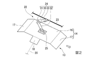
図1及び図2に示すように、受電部13は、車体12の屋上12aの外面に設けられている。そして、アルミニウム、銅、ステンレス等の金属を材料とした板状部14と、板状部14と車体12の外面との間に設けられた支持部15とを有している。
As shown in FIGS. 1 and 2, the
板状部14は、車体12の屋上12a外面に沿って車両2の進退方向となる車体12の前後方向、及び車体12の幅方向に延在する平板面16と、平板面16の前後方向に接続されて、平板面16から前後方向に離間するに従って、車体12の外面に近接するように延びる前後一対のテーパ面17(案内面)とを有している。本実施形態では、このテーパ面17は平板状をなしている。
The plate-
さらに、この板状部14は、車体12の幅方向の一方に向かって突出するように平板面16に接続された端子面18を有している。そして、この端子面18と蓄電池9とが配線20によって電気的に接続されている。なお、端子面18は、蓄電池9と板状部14との電気的な接続を行うものであるため、上述の形状には限定されない。また、端子面18を設けず、直接板状部14と蓄電池9とを配線20によって電気的に接続してもよい。
Further, the plate-
支持部15は、車体12の屋上12aに設けられた不図示の絶縁用碍子を介して、屋上12a外面に板状部14の平板面16を固定している。
The
地上設備5は、例えば駅などに設けられて、給電部22と、この給電部22を支持する構造物23と、車両2が駅に停車中に変電所からの電力を給電部22へ供給する充電器(不図示)、及び充電時間や充電量の制御を行う制御装置(不図示)とを有している。
The
給電部22は、車両2が駅で所定の位置に停車している際に、受電部13の上方で構造物23から受電部13に向かって延びるリンク部材24を有している。
また、受電部13における平板面16と接触可能となるように、リンク部材24に取り付けられ、平板面16との接触によって地上設備5からの電力を受電部13へ供給する給電シュー25とを有している。
The
The
リンク部材24は、構造物23から下方に向かうに従って前後方向の一方(本実施形態では後方)に延び、構造物23との間で三次元的に相対回動可能に設けられた第一連結部材30と、第一連結部材30の下方の端部に第一連結部材30に対して三次元的に相対回動可能に取り付けられた回動部材31とを有している。
The
また、リンク部材24は、回動部材31に取り付けられて、下方に向かうに従って前後方向の他方(本実施形態では前方)に延びる第二連結部材32と、回動部材31と構造物23との間に設けられたバネ33(付勢部)とを有している。そしてこのバネ33は、受電部13に給電シュー25を押し付けるように、受電部13に向かって給電シュー25に付勢力を与えるものであればよく、コイルバネや板バネ等、様々なもの用いることができる。
The
給電シュー25は、焼結金属やカーボン等を材料としており、第二連結部材32の下端に取り付けられて板状をなし、リンク部材24を通じて地上設備5における上記充電器に電気的に接続されている。また、この給電シュー25の表面積は、受電部13の平板面16の表面積に比べて小さくなっている。
The feeding
ここで、交通システム1は、受電部13と給電部22とが接触している際の接触状態を検知する接触検知部35をさらに備えている。
Here, the traffic system 1 further includes a
この接触検知部35には、例えば、給電シュー25と平板面16との距離を検知可能な公知の距離センサや、給電シュー25と平板面16との接触時に負荷インピーダンスの変化を検知する装置等を用いることができ、例えば上述した地上設備5における制御装置(不図示)に設けられている。
The
次に、図3を参照して、車両2への給電方法の手順を説明する。
給電方法は、駅において給電が行われる所定の給電位置に車両2を停車させる際に、テーパ面17によって給電シュー25を案内する案内工程S1と、停車位置の調整を行う車両位置調整工程S2とを備えている。
また、この給電方法は、車両2の停車位置が所定の給電位置となった場合に、受電部13と給電部22との間の接触状態を確認する接触確認工程S3と、接触状態を調整する接触調整工程S4とを備えている。
さらに、この給電方法は、接触調整工程S4の後に、給電部22からの給電を開始する給電工程S5と、蓄電池9への所定量の電力の給電が完了した際に給電を終了する給電完了工程S6と、その後、車両2を発進させる車両発進工程S7とを備えている。
Next, with reference to FIG. 3, the procedure of the power feeding method to the
The power feeding method includes a guidance process S1 for guiding the
Further, in this power feeding method, when the stop position of the
Furthermore, this power supply method includes a power supply step S5 for starting power supply from the
まず、案内工程S1が実行される。
案内工程S1では、図4(a)に示すように、給電部22の給電シュー25は、車両2の進行にともなって受電部13のテーパ面17に接触し、バネ33の付勢力に抗して給電シュー25が上方に持ち上げられる。そしてこのまま車両2の進行にともなって、給電シュー25がさらに上方に持ち上げられながら給電シュー25がテーパ面17上を案内される。この際、本実施形態の給電部22では、バネ33は伸長するように変形する。
First, guidance process S1 is performed.
In the guiding step S 1, as shown in FIG. 4A, the
さらに、図4(b)に示すように、テーパ面17と平板面16との接続部分を給電シュー25が超えると、バネ33の伸長が停止して一定の長さを保ったまま、給電シュー25が平板上にバネ33の付勢力によって付勢された状態で、車両2の進行に応じて平板面16上を移動する。
Further, as shown in FIG. 4B, when the
そして、図4(c)に示すように、車両2が停止すると、平板上の前後方向の略中央位置に給電シュー25が停止することになる。この位置が上述した所定の給電位置となる。
And as shown in FIG.4 (c), when the
このように車両2が停止した時点で、車両2の停止位置の確認を行う(S11)。そして、停止位置が上述の所定の給電位置となっていると判断された場合には、接触確認工程S3を実行する。一方で、停止位置が所定の給電位置となっていないと判断された場合には、車両位置調整工程S2を実行し、所定の給電位置に車両2が停止した後に接触確認工程S3を実行する。ここで、車両2の停止位置の確認は目視によって行ってもよいし、別途、車両2の位置を検出する位置センサ等によって行ってもよい。
Thus, when the
車両位置調整工程S2では、車両2を前後方向に進退させて、所定の給電位置に車両2が位置するように停止位置を調整する。
In the vehicle position adjustment step S2, the
接触確認工程S3では、接触検知部35からの検知信号に応じて、受電部13の平板面16と給電部22の給電シュー25とが確実に接触しているか否かを確認し(S12)、確実に接触していると判断された場合には、給電工程S5を実行する。一方で、確実に接触していないと判断された場合には接触調整工程S4を実行し、確実に接触している状態となった後に給電工程S5を実行する。
In the contact confirmation step S3, according to the detection signal from the
接触調整工程S4では、車両2、受電部13、給電部22のうちの少なくとも一つの位置調整を行う。車両2の位置調整は車両2を前後方向に進退させることで行う。また、受電部13及び給電部22の位置調整はこれらを手動で調整してもよいし、電動機や制御装置を別途設けて、これら受電部13及び給電部22の位置調整を遠隔操作によって行ってもよい。この場合、給電部22では回動部材31を三次元的に動作させ、受電部13では、例えば支持部15を三次元的に動作させるなどの手法によって位置調整が可能となる。
In the contact adjustment step S4, position adjustment of at least one of the
給電工程S5では、予め設定した電力を蓄電池9に給電する。そして、蓄電池9における電圧が所定値以上の値になったか否かを確認し(S13)、所定値以上となったと判断された場合には、給電完了工程S6を実行する。一方で、電圧が所定値に満たない場合には給電を継続し、所定値以上となった後に給電完了工程S6を実行する。 In the power supply step S <b> 5, power set in advance is supplied to the storage battery 9. And it is confirmed whether the voltage in the storage battery 9 became a value more than a predetermined value (S13), and when it is judged that it became more than a predetermined value, electric power supply completion process S6 is performed. On the other hand, when the voltage is less than the predetermined value, the power supply is continued, and the power supply completion step S6 is performed after the voltage becomes equal to or higher than the predetermined value.
給電完了工程S6では、受電部13の平板面16に給電シュー25が接触した状態で、地上設備5からの給電が停止されることで給電が終了し、車両発進工程S7へ進む。
In the power supply completion process S6, the power supply from the
車両発進工程S7では、給電完了工程S6の後、車両2を発進させる。
In the vehicle start process S7, the
このような交通システム1においては、車両2の前進に応じて給電部22の給電シュー25が、テーパ面17に押されながら平板面16へと案内される。従って、上述したように仮に車体12の幅方向の一方側が低くなり、他方側が高くなるように車両2が傾いていたとしても、テーパ面17がバネ33の付勢力に抗して給電シュー25を平板面16へと円滑に確実に案内することができる。
In such a traffic system 1, the feeding
さらに、給電シュー25がバネ33によって受電部13に付勢されるため、このように車体12が傾いた状態であっても、給電シュー25が受電部13の平板面16に押し付けられて、良好な接触状態を確保することができる。
Further, since the
また、接触検知部35によって、確実に受電部13と給電部22とが接触しているか否を確認することができる。従って、接触検知部35での検知結果に応じて車両2、受電部13、給電部22の位置調整を行って、受電部13と給電部22との接触状態の調整を行うことが可能となり、より良好な接触状態での給電が可能となる。
In addition, the
以上のように、本実施形態の交通システム1によると、受電部13のテーパ面17及びバネ33によって、車両2の姿勢によらず給電が可能となる。
As described above, according to the traffic system 1 of the present embodiment, the
ここで、給電部22と受電部13との構成が逆になっていてもよい。即ち、図5に示すように、給電部22側が板状部14と支持部15とを有する構成となっており、受電部13側がリンク部材24とシューとを有する構成となっていてもよい。
Here, the configurations of the
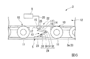
また、図6に示すように、受電部13は車体12の床下部の外面に設けられていてもよく、この場合、受電部13の下方で、受電部13の平板面16に対向するように給電部22が軌道3に設けられており、受電部13のテーパ面17は、給電部22から離間するように、平板面16との接続部分から前後方向に離間するに従って、上方に向かって傾斜して延びている。
In addition, as shown in FIG. 6, the
さらに、図7に示すように、受電部13は車体12の側面部の外面に設けられていてもよい。この場合、受電部13のテーパ面17は、給電部22に対して離間するように平板面16との接続部分から前後方向に離間するに従って、車体12の幅方向の内側に向かって傾斜して延びている。
Furthermore, as shown in FIG. 7, the
そして、受電部13の設置位置は上述の場合に限定されず、例えば第三軌条方式の交通システムのように、レール3aに給電部22を平設し、この給電部22に対向するように受電部13を設けて車両2への給電を行うようにしてもよい。
And the installation position of the
〔第二実施形態〕
次に、本発明の第二実施形態に係る交通システム1Aについて説明する。
なお、第一実施形態と同様の構成要素には同一の符号を付して詳細説明を省略する。
本実施形態では、給電部22が第一実施形態とは異なっている。
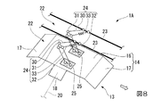
図8に示すように、給電部22は、車体12幅方向に複数(本実施形態では二つ)が並設されている。
各々の給電部22における給電シュー25は、車両2が給電位置に位置した際には、受電部13の平板面16上から前後方向、車体12の幅方向に逸脱しないように、平板面16内に位置するようになっている。
[Second Embodiment]
Next, the
In addition, the same code | symbol is attached | subjected to the component similar to 1st embodiment, and detailed description is abbreviate | omitted.
In this embodiment, the electric
As shown in FIG. 8, a plurality of (two in the present embodiment)
The
本実施形態の交通システム1Aによると、複数の給電部22によって高電流での給電が可能となる。そしてこの際、給電部22一つ当たりの負荷を低減できるため、各々の給電部22の構造を簡素化できる。
According to the traffic system 1 </ b> A of the present embodiment, it is possible to supply power at a high current by the plurality of
さらに、いずれかの給電部22に不具合が発生したとしても、他の給電部22によって給電が可能となる。即ち、フェールセーフ機能を有することになり、車両2への安定的な給電が可能となる。
Furthermore, even if a problem occurs in any of the
〔第三実施形態〕
次に、本発明の第三実施形態に係る交通システム1Bについて説明する。
なお、第一実施形態及び第二実施形態と同様の構成要素には同一の符号を付して詳細説明を省略する。
本実施形態では、第二実施形態を基本構成として、受電部13が第二実施形態とは異なっている。
図9に示すように、給電部22は、第二実施形態同様に車体12の幅方向に複数(本実施形態では二つ)が並設され、さらに受電部13が、車体12の幅方向に複数(本実施形態では二つ)が並設されている。
[Third embodiment]
Next, the
In addition, the same code | symbol is attached | subjected to the component similar to 1st embodiment and 2nd embodiment, and detailed description is abbreviate | omitted.
In the present embodiment, the
As shown in FIG. 9, a plurality of power feeding units 22 (two in the present embodiment) are arranged in parallel in the width direction of the
複数の受電部13同士は、隣接する受電部13のうちの一方の受電部13における端子面18と、他方の受電部13における平板面16とが接続されることで、電気的に接続されている。
The plurality of
また、各々の給電部22における給電シュー25は、車両2が給電位置に位置した際には、一の給電シュー25が、一の受電部13における平板面16上から前後方向、幅方向に逸脱しないように位置する。即ち、給電時には、一の給電部22と一の受電部13とが、一対一で接触するようになっている。
Further, the
本実施形態の交通システム1Bによると、複数の受電部13によって高電流での給電が可能となる。そしてこの際、受電部13一つ当たりの負荷を低減できるため、各々の受電部13の構造を簡素化できる。
According to the traffic system 1 </ b> B of the present embodiment, power can be supplied with a high current by the plurality of
さらに、いずれかの受電部13に不具合が発生したとしても、他の受電部13によって給電部22から受電することが可能となる。即ち、フェールセーフ機能を有することになり、車両2への安定的な給電が可能となる。
Furthermore, even if a problem occurs in any of the
なお、本実施形態では、複数の給電部22と、複数の受電部13とによって給電を行うようになっているが、例えば、複数の給電部22に対して一つの受電部13を設け、このような複数の給電部22と一つの受電部13とからなる構成を複数並設してもよい。即ち、第二実施形態における給電部22及び受電部13の構成を幅方向に複数並設することになる。
In the present embodiment, power is supplied by the plurality of
以上、本発明の実施形態について詳細を説明したが、本発明の技術的思想を逸脱しない範囲内において、多少の設計変更も可能である。
例えば、テーパ面の形状は上述の場合に限定されず、曲面状をなしてもよく、給電シュー25を平板面16に案内可能な案内面となっていればよい。
Although the embodiment of the present invention has been described in detail above, some design changes can be made without departing from the technical idea of the present invention.
For example, the shape of the tapered surface is not limited to the above-described case, and may be a curved surface as long as the feeding
また、上述の実施形態では、架線レスの新交通システム1、1A、1Bにおける給電について説明したが、例えば電気バスへの給電等、他の電気車両に適用してもよい。
Moreover, although the above-mentioned embodiment demonstrated the electric power feeding in the overhead line-less
1、1A、1B…交通システム 2…車両 3…軌道 3a…レール 5…地上設備 9…蓄電池 10…台車 11…車輪 12…車体 12a…屋上 13…受電部 14…板状部 15…支持部 16…平板面 17…テーパ面 18…端子面 20…配線 22…給電部 23…構造物 24…リンク部材 25…給電シュー 30…第一連結部材 31…回動部材 32…第二連結部材 33…バネ(付勢部) 35…接触検知部 S1…案内工程 S2…車両位置調整工程 S3…接触確認工程 S4…接触調整工程 S5…給電工程 S6…給電完了工程 S7…車両発進工程
DESCRIPTION OF
Claims (7)
前記受電部に接触することで該受電部に給電する給電部を有する地上設備と、
を備え、
前記受電部と前記給電部とのいずれか一方が、該一方を他方に向かって付勢力を与えるリンク部材を有し、
前記他方が、
前記車両の前記外面に沿って延在する平板面と、
該平板面における前記車両の進退方向に接続されて、前記車両の進退時に前記一方を前記付勢力に抗して前記平板面に案内して該平板面と接触させる案内面と、
を有し、
前記地上設備に設けられて、前記受電部と前記給電部との接触状態を検知する接触検知部をさらに備え、
前記リンク部材は、前記一方から前記他方に向かって延び、前記他方との間で三次元的に相対回動可能に設けられた第一連結部材と、該第一連結部材の端部に該第一連結部材に対して三次元的に相対回動可能に設けられた回動部材と、該回動部材に取り付けられて、前記一方から前記他方に延びる第二連結部材と、該第二連結部材に設けられて前記他方に接触する給電シューと、前記回動部材と前記一方との間に設けられて前記給電シューを前記他方の前記平板面に付勢する付勢部とを有していることを特徴とする交通システム。 A vehicle having a power receiving unit on the outer surface;
Ground equipment having a power feeding unit that feeds power to the power receiving unit by contacting the power receiving unit;
With
Either one of the power receiving unit and the power feeding unit has a link member that applies a biasing force toward the other.
The other is
A flat plate surface extending along the outer surface of the vehicle;
A guide surface connected to the flat plate surface in the advancing and retreating direction, and guiding the one to the flat plate surface against the urging force when the vehicle advances and retreats;
Have
Provided in the ground facility, further comprising a contact detection unit for detecting a contact state between the power receiving unit and the power feeding unit;
The link member extends toward the other from the one, and the first connecting member provided relatively rotatably in three dimensions between the other, said the end of the first connecting member A rotating member provided to be rotatable relative to one connecting member in three dimensions, a second connecting member attached to the rotating member and extending from the one to the other, and the second connecting member It provided has a feed shoe in contact with the other, and said urging portion for urging the feeding shoe provided between the rotating member and the one on the flat surface of the other A traffic system characterized by that.
前記一方を、前記付勢力に抗して前記案内面によって前記平板面に案内して接触させる案内工程と、
案内工程の後に給電を開始する給電工程と、
予め設定した電力を給電完了した際に、給電を終了する給電完了工程と、
を備えることを特徴とする給電方法。 A power feeding method for feeding power to the power receiving unit by the power feeding unit in the traffic system according to claim 1,
A guide step in which the one is guided and brought into contact with the flat plate surface by the guide surface against the biasing force;
A power feeding process for starting power feeding after the guidance process;
A power supply completion step of terminating power supply when power supply of a preset power is completed;
A power supply method comprising:
前記接触確認工程の結果に基づいて前記車両、前記受電部、及び前記給電部のうちの少なくとも一つの位置調整を行って接触状態を調整する接触調整工程と、
をさらに備えることを特徴とする請求項6に記載の給電方法。 In accordance with a signal from the contact detection unit that is provided in the ground facility and detects a contact state between the power reception unit and the power supply unit between the guidance process and the power supply process, the power reception unit and the power supply A contact confirmation process for confirming the contact state with the part,
A contact adjusting step of adjusting a contact state by adjusting the position of at least one of the vehicle, the power receiving unit, and the power feeding unit based on a result of the contact confirmation step;
The power feeding method according to claim 6, further comprising:
Priority Applications (4)
| Application Number | Priority Date | Filing Date | Title |
|---|---|---|---|
| JP2013084183A JP6327412B2 (en) | 2013-04-12 | 2013-04-12 | Transportation system and power supply method |
| US14/777,292 US9969299B2 (en) | 2013-04-12 | 2014-04-04 | Traffic system and power supply method |
| PCT/JP2014/059970 WO2014168086A1 (en) | 2013-04-12 | 2014-04-04 | Traffic system and power supply method |
| SG11201506321VA SG11201506321VA (en) | 2013-04-12 | 2014-04-04 | Traffic system and power supply method |
Applications Claiming Priority (1)
| Application Number | Priority Date | Filing Date | Title |
|---|---|---|---|
| JP2013084183A JP6327412B2 (en) | 2013-04-12 | 2013-04-12 | Transportation system and power supply method |
Publications (3)
| Publication Number | Publication Date |
|---|---|
| JP2014207788A JP2014207788A (en) | 2014-10-30 |
| JP2014207788A5 JP2014207788A5 (en) | 2015-09-17 |
| JP6327412B2 true JP6327412B2 (en) | 2018-05-23 |
Family
ID=51689495
Family Applications (1)
| Application Number | Title | Priority Date | Filing Date |
|---|---|---|---|
| JP2013084183A Active JP6327412B2 (en) | 2013-04-12 | 2013-04-12 | Transportation system and power supply method |
Country Status (4)
| Country | Link |
|---|---|
| US (1) | US9969299B2 (en) |
| JP (1) | JP6327412B2 (en) |
| SG (1) | SG11201506321VA (en) |
| WO (1) | WO2014168086A1 (en) |
Families Citing this family (7)
| Publication number | Priority date | Publication date | Assignee | Title |
|---|---|---|---|---|
| CN104442454A (en) * | 2014-12-02 | 2015-03-25 | 北京赛德高科铁道电气科技有限责任公司 | Charging device of energy-storage type electric vehicle |
| CN107225975B (en) * | 2017-05-16 | 2019-08-13 | 汕头市众业达电器设备有限公司 | Electric car charging bow mounting structure |
| DE102018129430B4 (en) * | 2018-11-22 | 2024-05-08 | Schunk Transit Systems Gmbh | Contact unit and charging system |
| JP7403245B2 (en) * | 2019-06-21 | 2023-12-22 | キヤノン株式会社 | Image decoding device, image decoding method |
| DE102019126557A1 (en) * | 2019-10-02 | 2021-04-08 | Liebherr-Mining Equipment Colmar Sas | Overhead line system for construction machinery for piece and bulk goods transport as well as construction machinery |
| CN110641285A (en) * | 2019-10-18 | 2020-01-03 | 中车株洲电力机车有限公司 | Backflow system for metro vehicle |
| CN113212254B (en) * | 2021-06-10 | 2023-06-20 | 贵州电网有限责任公司 | Method for reducing urban rail transit track potential by considering train stop time |
Family Cites Families (15)
| Publication number | Priority date | Publication date | Assignee | Title |
|---|---|---|---|---|
| US3002059A (en) * | 1958-04-09 | 1961-09-26 | Porter Co Inc H K | Distributed contact system |
| USRE29994E (en) * | 1973-02-15 | 1979-05-15 | Electric traction transportation system with storage battery powered vehicles and fast recharge at the vehicle stops | |
| JPH0984213A (en) * | 1995-09-14 | 1997-03-28 | Toyota Autom Loom Works Ltd | Automatic charging system and charging device of vehicle |
| JPH104604A (en) * | 1996-06-12 | 1998-01-06 | Toyo Electric Mfg Co Ltd | Current-correcting device for vehicle in new transit system |
| JP2002191103A (en) * | 2000-12-19 | 2002-07-05 | Matsushita Electric Ind Co Ltd | Unmanned transporting vehicle and charging and discharging method and charging apparatus for secondary battery thereof |
| DE10313698A1 (en) * | 2003-03-27 | 2005-05-12 | Ekkehard Lefeldt | Power supply device for electrically driven rail-borne vehicles, has railway contacts arranged along rails with contact arms spaced from one another |
| JP4369382B2 (en) * | 2005-03-01 | 2009-11-18 | 三菱電機株式会社 | Transportation system |
| JP4568736B2 (en) * | 2007-02-27 | 2010-10-27 | 三菱重工業株式会社 | Overhead-less transportation system and charging method thereof |
| CN102123882A (en) | 2008-07-01 | 2011-07-13 | 普罗特拉公司 | Charging stations for electric vehicles |
| FR2942750B1 (en) * | 2009-03-09 | 2017-11-24 | Lohr Ind | AIR ASSEMBLY FOR PROVIDING ELECTRICAL POWER TO A GROUND VEHICLE. |
| JP2013515645A (en) | 2009-12-23 | 2013-05-09 | プロテラ インコーポレイテッド | Charging station for electric vehicles |
| JP2011167042A (en) * | 2010-02-15 | 2011-08-25 | Mitsubishi Heavy Ind Ltd | Power supplying system |
| FR2957861B1 (en) * | 2010-03-29 | 2014-11-07 | Lohr Ind | UPPER SIDE STRUCTURE FOR OCCASIONAL OR CONTINUOUS CAPACITORING OF MOTOR OR AUXILIARY ELECTRIC POWER BY A GROUND VEHICLE |
| JP2012080628A (en) * | 2010-09-30 | 2012-04-19 | Kawasaki Heavy Ind Ltd | Charging system for electric vehicle |
| FR2981016B1 (en) * | 2011-10-06 | 2015-05-29 | Lohr Ind | ELECTRIC POWER SUPPLY ASSEMBLY WITH ELECTRICAL CONTACT PLUGGING ON A POWER SUPPLY RECEIVER TRACK RUN BY AN ELECTRIC PROPULSION VEHICLE. |
-
2013
- 2013-04-12 JP JP2013084183A patent/JP6327412B2/en active Active
-
2014
- 2014-04-04 SG SG11201506321VA patent/SG11201506321VA/en unknown
- 2014-04-04 US US14/777,292 patent/US9969299B2/en active Active
- 2014-04-04 WO PCT/JP2014/059970 patent/WO2014168086A1/en active Application Filing
Also Published As
| Publication number | Publication date |
|---|---|
| SG11201506321VA (en) | 2015-10-29 |
| WO2014168086A1 (en) | 2014-10-16 |
| US9969299B2 (en) | 2018-05-15 |
| US20160046206A1 (en) | 2016-02-18 |
| JP2014207788A (en) | 2014-10-30 |
Similar Documents
| Publication | Publication Date | Title |
|---|---|---|
| JP6327412B2 (en) | Transportation system and power supply method | |
| EP2504190B1 (en) | Electric vehicle charging station and charge receiving arrangement for a vehicle | |
| CN101541583B (en) | Catenary-less transportation system and its charging method | |
| US11712969B2 (en) | Current collector device for a vehicle | |
| AU2014246942B2 (en) | Connecting apparatus for connecting an electrically powered vehicle to a charging station | |
| CN108136917B (en) | Quick charging system and method for electrically connecting a vehicle to a charging station | |
| CN107298023B (en) | Vehicle charging connector | |
| US20170210238A1 (en) | Vehicle Charging Station Comprising A Supply-Contact Device Mounted On An Arm | |
| US20170349055A1 (en) | Apparatus and method for electrically connecting a charging station to a charging socket of a vehicle | |
| US20170217324A1 (en) | Vehicle charging station with an articulated arm | |
| EP2848451A1 (en) | Connection system for charging batteries of a vehicle, particularly an electric bus | |
| CN105244933A (en) | Externally rechargeable vehicle having an electric drive and recharging station for the vehicle | |
| PL230883B1 (en) | System for quick charging of vehicles equipped with electric drive | |
| CN110225841A (en) | Contact point unit and contact method for charging station | |
| WO2011155232A1 (en) | Crane system | |
| CN111975277A (en) | Welding equipment and welding method for reinforcement cage | |
| US4603237A (en) | Automatic connection and disconnection of current collectors for trolley vehicles | |
| CN212286507U (en) | Steel reinforcement cage welding equipment | |
| EP2981432B1 (en) | Connecting apparatus for connecting an electrically powered vehicle to a charging station | |
| CN117615934A (en) | Quick charging system |
Legal Events
| Date | Code | Title | Description |
|---|---|---|---|
| A521 | Request for written amendment filed |
Free format text: JAPANESE INTERMEDIATE CODE: A523 Effective date: 20150731 |
|
| A621 | Written request for application examination |
Free format text: JAPANESE INTERMEDIATE CODE: A621 Effective date: 20150731 |
|
| A521 | Request for written amendment filed |
Free format text: JAPANESE INTERMEDIATE CODE: A821 Effective date: 20150803 |
|
| A131 | Notification of reasons for refusal |
Free format text: JAPANESE INTERMEDIATE CODE: A131 Effective date: 20160621 |
|
| A521 | Request for written amendment filed |
Free format text: JAPANESE INTERMEDIATE CODE: A523 Effective date: 20160822 |
|
| A521 | Request for written amendment filed |
Free format text: JAPANESE INTERMEDIATE CODE: A821 Effective date: 20160823 |
|
| A131 | Notification of reasons for refusal |
Free format text: JAPANESE INTERMEDIATE CODE: A131 Effective date: 20170131 |
|
| A521 | Request for written amendment filed |
Free format text: JAPANESE INTERMEDIATE CODE: A523 Effective date: 20170403 |
|
| A521 | Request for written amendment filed |
Free format text: JAPANESE INTERMEDIATE CODE: A821 Effective date: 20170404 |
|
| A131 | Notification of reasons for refusal |
Free format text: JAPANESE INTERMEDIATE CODE: A131 Effective date: 20171003 |
|
| A521 | Request for written amendment filed |
Free format text: JAPANESE INTERMEDIATE CODE: A523 Effective date: 20171204 |
|
| A521 | Request for written amendment filed |
Free format text: JAPANESE INTERMEDIATE CODE: A821 Effective date: 20171205 |
|
| TRDD | Decision of grant or rejection written | ||
| A01 | Written decision to grant a patent or to grant a registration (utility model) |
Free format text: JAPANESE INTERMEDIATE CODE: A01 Effective date: 20180306 |
|
| A711 | Notification of change in applicant |
Free format text: JAPANESE INTERMEDIATE CODE: A712 Effective date: 20180323 |
|
| A61 | First payment of annual fees (during grant procedure) |
Free format text: JAPANESE INTERMEDIATE CODE: A61 Effective date: 20180403 |
|
| R150 | Certificate of patent or registration of utility model |
Ref document number: 6327412 Country of ref document: JP Free format text: JAPANESE INTERMEDIATE CODE: R150 |
|
| S533 | Written request for registration of change of name |
Free format text: JAPANESE INTERMEDIATE CODE: R313533 |
|
| R350 | Written notification of registration of transfer |
Free format text: JAPANESE INTERMEDIATE CODE: R350 |
|
| S111 | Request for change of ownership or part of ownership |
Free format text: JAPANESE INTERMEDIATE CODE: R313111 |
|
| R350 | Written notification of registration of transfer |
Free format text: JAPANESE INTERMEDIATE CODE: R350 |