WO2013187499A1 - 照明装置 - Google Patents
照明装置 Download PDFInfo
- Publication number
- WO2013187499A1 WO2013187499A1 PCT/JP2013/066440 JP2013066440W WO2013187499A1 WO 2013187499 A1 WO2013187499 A1 WO 2013187499A1 JP 2013066440 W JP2013066440 W JP 2013066440W WO 2013187499 A1 WO2013187499 A1 WO 2013187499A1
- Authority
- WO
- WIPO (PCT)
- Prior art keywords
- light
- light source
- main body
- lens
- cover
- Prior art date
- Legal status (The legal status is an assumption and is not a legal conclusion. Google has not performed a legal analysis and makes no representation as to the accuracy of the status listed.)
- Ceased
Links
Images













Classifications
-
- F—MECHANICAL ENGINEERING; LIGHTING; HEATING; WEAPONS; BLASTING
- F21—LIGHTING
- F21S—NON-PORTABLE LIGHTING DEVICES; SYSTEMS THEREOF; VEHICLE LIGHTING DEVICES SPECIALLY ADAPTED FOR VEHICLE EXTERIORS
- F21S8/00—Lighting devices intended for fixed installation
- F21S8/04—Lighting devices intended for fixed installation intended only for mounting on a ceiling or the like overhead structures
-
- F—MECHANICAL ENGINEERING; LIGHTING; HEATING; WEAPONS; BLASTING
- F21—LIGHTING
- F21V—FUNCTIONAL FEATURES OR DETAILS OF LIGHTING DEVICES OR SYSTEMS THEREOF; STRUCTURAL COMBINATIONS OF LIGHTING DEVICES WITH OTHER ARTICLES, NOT OTHERWISE PROVIDED FOR
- F21V5/00—Refractors for light sources
- F21V5/04—Refractors for light sources of lens shape
-
- F—MECHANICAL ENGINEERING; LIGHTING; HEATING; WEAPONS; BLASTING
- F21—LIGHTING
- F21V—FUNCTIONAL FEATURES OR DETAILS OF LIGHTING DEVICES OR SYSTEMS THEREOF; STRUCTURAL COMBINATIONS OF LIGHTING DEVICES WITH OTHER ARTICLES, NOT OTHERWISE PROVIDED FOR
- F21V7/00—Reflectors for light sources
- F21V7/0008—Reflectors for light sources providing for indirect lighting
-
- F—MECHANICAL ENGINEERING; LIGHTING; HEATING; WEAPONS; BLASTING
- F21—LIGHTING
- F21V—FUNCTIONAL FEATURES OR DETAILS OF LIGHTING DEVICES OR SYSTEMS THEREOF; STRUCTURAL COMBINATIONS OF LIGHTING DEVICES WITH OTHER ARTICLES, NOT OTHERWISE PROVIDED FOR
- F21V7/00—Reflectors for light sources
- F21V7/0025—Combination of two or more reflectors for a single light source
-
- F—MECHANICAL ENGINEERING; LIGHTING; HEATING; WEAPONS; BLASTING
- F21—LIGHTING
- F21V—FUNCTIONAL FEATURES OR DETAILS OF LIGHTING DEVICES OR SYSTEMS THEREOF; STRUCTURAL COMBINATIONS OF LIGHTING DEVICES WITH OTHER ARTICLES, NOT OTHERWISE PROVIDED FOR
- F21V7/00—Reflectors for light sources
- F21V7/0025—Combination of two or more reflectors for a single light source
- F21V7/0033—Combination of two or more reflectors for a single light source with successive reflections from one reflector to the next or following
-
- F—MECHANICAL ENGINEERING; LIGHTING; HEATING; WEAPONS; BLASTING
- F21—LIGHTING
- F21Y—INDEXING SCHEME ASSOCIATED WITH SUBCLASSES F21K, F21L, F21S and F21V, RELATING TO THE FORM OR THE KIND OF THE LIGHT SOURCES OR OF THE COLOUR OF THE LIGHT EMITTED
- F21Y2115/00—Light-generating elements of semiconductor light sources
- F21Y2115/10—Light-emitting diodes [LED]
Definitions
- the present invention relates to a lighting device including a light source and a lens that refracts light emitted from the light source.
- an illumination device including a light source composed of a semiconductor light emitting element such as a light emitting diode (LED) and a lens for refracting light emitted from the light source has been used.
- a light source composed of a semiconductor light emitting element such as a light emitting diode (LED) and a lens for refracting light emitted from the light source has been used.
- LED light emitting diode
- Patent Document 1 discloses a semiconductor light emitting device as a light source, a light guide having an incident surface facing a light emitting portion of the semiconductor light emitting device, and light incident from the light source through the light guide into parallel light.
- An illumination device including a lens that converts and emits light is disclosed.
- the illuminating device disclosed in Patent Document 1 includes a support portion erected on the outer edge portion of the chassis, and the LED as a light source is supported by the support portion so as to face the center side of the chassis. Yes.
- a light guide and a lens body are disposed opposite to each other on the light emission side of the LED, and light emitted from the LED is emitted toward the center of the illumination device via the light guide and the lens body.
- the present invention has been made in view of the above problems, and an object of the present invention is to provide an illumination device that can distribute light to a region opposite to the light emission direction of the light source using light emitted from the light source. It is to provide.
- the illuminating device of the present invention is an illuminating device that includes a main body portion and a light source that emits light in the surface direction of the main body portion, and is disposed on the light emission direction side of the illuminating device with respect to the light source. And a first reflecting member for reflecting a part of the light emitted from the light source to a region opposite to the light emitting direction of the light source.
- a part of the light emitted from the light source can be reflected by the first reflecting member and guided to the region opposite to the light emitting direction of the light source. Thereby, it can distribute to the area
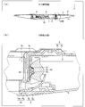
- FIG. 1 is a cross-sectional view of the AA cross section shown in FIG. 1, and (b) is an enlarged view of a portion B shown in (a).
- FIG. 1 is the perspective view of the adapter cover with which the illuminating device shown in FIG. 1 is equipped
- (b) is sectional drawing which showed typically the state which attached the adapter cover shown to (a) to the illuminating device. is there.
- C) is a perspective view which shows the modification of the adapter cover shown to (a).
- FIG. 2 is an exploded perspective view of a power supply unit and a sensor unit provided in the lighting device shown in FIG.
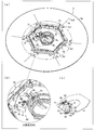
- (A) is explanatory drawing which shows the state which accommodated the sensor unit in the power supply accommodating part of the power supply cover, and has shown the surface of the floor side of a sensor unit.
- the (B) is the enlarged view of the D section shown to (a).
- (C) is explanatory drawing which shows the attachment method with respect to the power supply unit of a sensor unit.
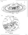
- (A) is explanatory drawing which shows the state which accommodated the sensor unit in the power supply accommodating part of the power supply cover, and has shown the surface by the side of the ceiling of a sensor unit.
- (B) is the enlarged view of the E section shown to (a).
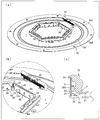
- (A) is explanatory drawing which shows the structure of a main body chassis and a light source unit.
- FIG. 15A is a wiring diagram of a light source substrate provided in the illumination device shown in FIG.
- FIGS. 14 (b) and 14 (c) are wiring diagrams of the light source substrate shown in FIGS. 14 (b) and 14 (c), respectively. It is explanatory drawing which shows the connection state of each light source board with which the illuminating device shown in FIG. 1 is equipped.
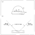
- (A) is explanatory drawing which shows the structure of the light source for main illuminations
- (b) is explanatory drawing which shows the structure of the light source for nightlights.
- (A) is a disassembled perspective view which shows the structure of the surface of the ceiling side of the dustproof cover with which the illuminating device shown in FIG. 1 is equipped
- (b) is an exploded perspective view which shows the structure of the floor side surface of the said dustproof cover. It is.
- FIG. 1 It is a top view which shows the state of the illuminating device before attaching a dust-proof cover. It is a perspective view which shows the state of the illuminating device after attaching a dustproof cover. It is sectional drawing which shows the state of the illuminating device after attaching a dustproof cover. It is a top view which shows the state of the illuminating device after attaching a dustproof cover. It is a disassembled perspective view of the main body chassis and reflection sheet with which the illuminating device shown in FIG. 1 is equipped. (A) is a top view of the reflective sheet attached to the main body chassis, (b) is a sectional view of the SS cross section shown in (a).
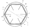
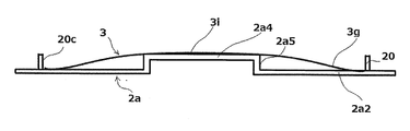
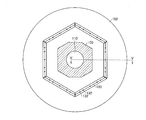
- FIG. 27 is a cross-sectional view of the lighting device according to FIG. 26 taken along the line TT.
- A is a top view of the reflective sheet attached to the main body chassis of the illuminating device which concerns on Embodiment 3 of this invention
- (b) is sectional drawing of the U cross section shown to (a).
- Embodiment 1 An embodiment of the present invention will be described.
- this embodiment demonstrates the case where this invention is applied to the ceiling light attached to ceilings, such as a house, the application object of this invention is not restricted to this.
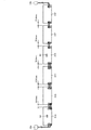
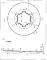
- FIG. 1 is a front view (a view seen from the floor side) and a side view showing the appearance of the lighting device 1 according to the present embodiment.
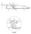
- 2 (a) is a cross-sectional view of the lighting device 1 taken along the line AA shown in FIG. 1, and
- FIG. 2 (b) is an enlarged view of a portion B shown in FIG. 2 (a). is there.
- FIG. 3 is an exploded perspective view of the lighting device 1.
- the lighting device 1 includes a chassis 2, a reflection sheet 3, a power supply unit 4, a power supply cover 5, an adapter 6, an adapter cover 7, a dust cover 8, a ring cover 9, and a center cover 10. ing.
- the chassis 2 is a member made of a metal material such as aluminum or iron for supporting each part provided in the lighting device 1, and includes a main body chassis 2a and a bottom chassis 2b as main body parts.
- the shape and material of the main body chassis 2a are not limited to the above-described configuration, and may be a resin material, ceramics, or the like as long as it has sufficient strength to support each part of the lighting device 1.
- the main body chassis 2a is preferably made of a material having high thermal conductivity in order to dissipate heat generated by the light source unit 30 described later to the outside.
- an opening that penetrates from the front surface side (ring cover 9 side), which is a surface on the emission direction side of the illumination light from the lighting device 1, to the back surface side (ceiling side) is provided.
- Six light source unit support portions 20 formed by bending the inner edge portion of the main body chassis 2a to the front surface side (floor side) are provided around the opening. That is, the light source unit support part 20 is formed integrally with the main body chassis 2a by bending a part of the main body chassis 2a.
- Each light source unit support portion 20 has substantially the same shape, and a bent portion 20a that is a ridge (a line segment of two surfaces) formed by the above-described bending is formed by the outer edge of the main body chassis 2a.
- each light source unit support part 20 is arrange
- the main body chassis 2a has a reflection sheet 3 to be described later on the illumination light emitting side.
- the six light source unit support portions 20 are arranged in a hexagonal shape, but the number and arrangement method of the light source unit support portions 20 are not limited to this.
- the light source unit support portions 20 are arranged in a quadrangular shape, an octagonal shape, or another polygonal shape, and the light sources 32 described later are arranged in a circumferential shape (polygonal shape) along the circumferential direction of the main body chassis 2a. It is good also as a structure provided in each light source unit support part 20.
- the main body chassis 2a as the main body portion of the lighting device 1 has a ring cover as the surface of the substantially annular plate-shaped member is moved to the outer peripheral side as shown in the cross-sectional views of FIGS. 5 and 24B.
- a stepped portion is provided on the surface so as to approach the 9 side.
- the step portion is provided over the entire circumference of the main body chassis 2a.
- the main body chassis 2a has an inner peripheral portion 2a1 (first surface) whose position in the orthogonal direction with respect to the surface (the surface on the ring cover 9 side) is substantially the same as the position in the orthogonal direction of the bent portion 20a.
- the inner peripheral portion 2a1 is a central region of the main body chassis 2a
- the outer peripheral portion 2a2 is a region on the outer peripheral side of the inner peripheral portion 2a1 in the main body chassis 2a.
- the inner peripheral part 2a1 and the outer peripheral part 2a2 are connected by a step part 2a3.
- press working is preferably used as a method for forming the inner peripheral portion 2a1, the outer peripheral portion 2a2, and the stepped portion 2a3, press working is preferably used.
- the power supply unit 4 In the opening (the region surrounded by each light source unit support portion 20) in the main body chassis 2a, the power supply unit 4, a part of the power supply cover 5, the adapter 6, the adapter mounting portions 6a and 6b, the adapter cover 7, and the dust cover A part of 8 is arranged.
- the power supply cover 5 is recessed in the floor side provided in the center part, the opening part 5a which has a shape according to the outer diameter shape of the adapter attachment parts 6a and 6b, and the circumference
- the power supply accommodating portion 5b having a shape with an opening on the ceiling side and the flange portion 5c substantially parallel to the ceiling surface provided around the power supply accommodating portion 5b are provided. Thereby, the power supply cover 5 accommodates the power supply unit 4 in the power supply accommodating part 5b, and protects the power supply unit 4.
- the outer peripheral part of the power supply accommodating part 5b becomes a shape which can be accommodated inside the six light source unit support parts 20 (center side of the circle
- the illumination device 1 can be made thinner than the case where the power supply unit 4 is accommodated in the main body of the illumination device 1 and the power supply unit is disposed closer to the ceiling than the area surrounded by the light source unit support portions 20. it can.
- the power supply unit (power supply board) 4 receives power supplied from the outside of the lighting device 1 and supplies it to each part of the lighting device 1 according to instructions from the user, detection results of various sensors, and the like.
- a circuit board such as a control circuit for controlling the light emission state of each light source is provided.
- the power supply unit 4 is arrange
- various sensors for example, an optical sensor for detecting the brightness around the lighting device 1 and a remote controller (not shown) for instructing the lighting device 1).
- a power cable for supplying power from the adapter 6 to the power supply unit 4 is connected to the power supply unit 4 via the sensor unit 40. Details of the configuration of the sensor unit 40 will be described later.
- the bottom chassis 2b is a substantially disk-shaped member having an opening corresponding to the outer diameter shape of the adapter 6, and is attached to the main body chassis 2a with the flange portion 5c of the power supply cover 5 sandwiched between the bottom chassis 2b and the main body chassis 2a. It is attached. Thereby, the power supply unit 4 and the sensor unit 40 are accommodated in the power supply accommodating portion 5b of the power supply cover 5, and the opening surface provided on the ceiling side of the power supply accommodating portion 5b is closed by the bottom chassis 2b. Further, in the present embodiment, by separating the main body chassis 2a and the bottom chassis 2b, heat generated in the light source unit 30 and transmitted to the main chassis 2a is transmitted to the power supply unit 4 via the bottom chassis 2b.
- the heat generated in the light source unit 30 and transmitted to the main body chassis 2a is mainly transferred to the outer edge side of the main body chassis 2a to be radiated.
- the material of the bottom chassis 2b is not specifically limited, For example, the material similar to the main body chassis 2a can be used.
- the adapter attachment portions 6a and 6b hold the adapter 6 when attaching the lighting device 1 to the ceiling (installation target) and play a role of hiding the edges of members made of metal such as the chassis 2 and the power supply cover 5.
- the adapter mounting portions 6 a and 6 b have a substantially annular shape (substantially cylindrical) whose outer diameter portion has a shape corresponding to the inner diameter shape of the opening 5 a of the power supply cover 5 and whose inner diameter portion has a shape corresponding to the outer diameter portion of the adapter 6. And is attached to the opening 5 a of the power supply cover 5.
- groove portions are provided for engaging a movable portion 6d of the adapter 6 described later.
- a part of the adapter mounting part 6a in the circumferential direction is provided with a notch part 6c communicating from the inner circumference side to the outer circumference side, and this notch part 6c is provided with a board side connector 48 described later. .
- the adapter 6 is a member for attaching the lighting device 1 to the ceiling, and at both ends in the diameter direction of the adapter 6, a movable part urged by an elastic member (not shown) such as a spring toward the outside in the diameter direction. 6d is provided. Further, as described above, a groove portion having a diameter corresponding to the movable portion 6d of the adapter 6 is provided on the inner peripheral surfaces of the adapter attachment portions 6a and 6b, and the movable portion 6d is either of the adapter attachment portions 6a and 6b.
- the lighting device 1 is attached to the ceiling by fitting in the groove.
- the lighting device 1 corresponds to two types of ceiling-side mounting members that have different heights from the ceiling, and the movable part of the adapter 6 depends on the type of the ceiling-side mounting member. 6d is adapted to be fitted into either of the groove portions of the adapter mounting portion 6a or the adapter mounting portion 6b.
- the inner edge portion of the adapter mounting portion 6a passes through the contact portion with the movable portion 6d of the adapter 6, and the movable portion 6d is provided on the inner peripheral surface of the adapter mounting portion 6a.
- the state of being fitted into the groove portion and being pushed inward in the diameter direction is released. Accordingly, the adapter mounting portions 6a and 6b are held in a state of being sandwiched between the ceiling and the movable portion 6d of the adapter 6, thereby fixing the lighting device 1 to the ceiling.
- the movable part 6d of the adapter 6 is fitted to the adapter attachment part 6a in the same manner as when fitting the adapter attachment part 6a.
- the structure in which the adapter mounting portions 6a and 6b, the power supply cover 5, the power supply unit 4, the main body chassis 2a, the bottom chassis 2b, and the reflection sheet 3 are assembled is further pushed up to the ceiling side.
- the inner edge part of the adapter attachment part 6b contacts the movable part 6d of the adapter 6, and the movable part 6d is pushed inward in the diameter direction.
- the inner edge portion of the adapter mounting portion 6b passes through the contact portion with the movable portion 6d of the adapter 6, and the movable portion 6d is provided on the inner peripheral surface of the adapter mounting portion 6b.
- the state of being fitted into the groove portion and being pushed inward in the diameter direction is released.
- the adapter attachment part 6b is hold
- the adapter 6 is connected to the power supply unit 4 (not shown) electrically connected to the power supply unit provided in the ceiling-side mounting member, and the power supplied to the power supply unit 4 through the power supply unit.
- a power cable 6e for supply is provided.
- the electrical connection portion of the adapter 6 is electrically connected to a power supply unit (not shown) provided on the ceiling side mounting member.
- an adapter-side connector 6f provided at the tip of the power cable 6e of the adapter 6 is connected to a board-side connector 48 (FIG. 9B described later) attached to the sensor unit 40 via the notch 6c of the adapter attachment 6a. )), Power is supplied to the power supply unit 4 via a power cable (not shown) extending from the board-side connector 48.
- the adapter 6 is mounted on the adapter mounting portion 6a or 6b and the lighting device 1 is mounted on the ceiling, the adapter 6 and the adapter mounting portions 6a and 6b are disposed on the floor side of the adapter mounting portion 6a.
- An adapter cover 7 is attached so as to cover the opening.
- FIG. 4A is a perspective view of the adapter cover 7, and FIG. 4B is a cross-sectional view schematically showing a state in which the adapter cover 7 is attached to the lighting device 1.
- the adapter cover 7 includes a reflective surface 7a and three claw portions 7b.
- the claw portion 7b is an engaging portion for attaching the adapter cover 7 to the lighting device 1.
- the claw portion 7b is engaged with the adapter attaching portion 6a, thereby causing the adapter cover 7 to be engaged. Is attached to the lighting device 1.
- the reflection surface 7a reflects the light irradiated from the light source unit 30 and reaching the reflection surface 7a to the center cover 10 side via the reflection portion (reflection member) 8a and the transmission portion (transmission member) 8b of the dust cover 8. . That is, as will be described later, in the present embodiment, the light emitted from the light source unit 30 is mainly emitted to the main illumination region, which is the region on the outer edge side of the illumination device 1 with respect to the light source unit support portion 20. Light that leaks from the light source unit 30 to the floor side is an area inside the illumination device 1 from the light source unit support part 20 through the reflection part 8a and the transmission part 8b of the dust cover 8 (area surrounded by each light source unit support part 20).
- the material of the adapter cover 7 is not particularly limited as long as at least the reflection surface 7a reflects light, and conventionally known materials can be used.
- the adapter cover 7 made of a highly reflective resin material is used.
- the reflective surface 7a and the claw portion 7b may be made of the same material or different materials.
- the reflecting portion 8a of the dustproof cover 8 and the reflecting surface 7a of the adapter cover 7 may have a property of diffusing and reflecting light.
- the light incident on the sub illumination area from the light source 32 via the lens 33 is reflected and diffused twice by the reflecting portion 8a and the reflecting surface 7a, and therefore enters the disc portion 10b of the center cover 10. It is possible to prevent the brightness unevenness due to the shape of the locking portion 54 of the lens 33 from occurring in the light.
- the locking portion 54 is partially provided along the extending direction of the lens 33 as in the present embodiment, uneven brightness easily occurs depending on the arrangement position and shape of the locking portion 54.
- uneven brightness can be appropriately prevented by reflecting and diffusing the reflection portion 8a and the reflection surface 7a doubly.
- the shape of the reflection surface 7a is convex toward the floor surface while gently curving from one end side to the other end side in the diameter direction of the adapter cover 7.
- the central portion in the diameter direction has a substantially flat shape, it is not limited to this.
- the adapter cover 7 may have a shape in which the central portion in the diametrical direction protrudes to the floor surface side. Thereby, it can illuminate efficiently to the center part of the center cover 10.
- the shape of the reflection surface 7a of the adapter cover 7 is formed such that the center portion is convex toward the floor surface side, so that the auxiliary cover is interposed via the reflection portion 8a and the transmission portion 8b of the dustproof cover 8. Light incident on the illumination area is efficiently reflected toward the center cover 10 by the reflecting surface 7a, so that the center cover 10 can be illuminated more uniformly.
- the dust-proof cover 8 has a reflecting portion 8a arranged to face the light source unit 30 at a position where the illumination light is emitted with respect to the light source unit 30, that is, on the opposite side of the main body sia-si2a, and the reflecting portion 8a.
- a transmissive portion 8b that is disposed inside the illumination device 1 and transmits light emitted from the light source unit 30 and reflected by the reflective portion 8a is provided.
- the transmissive portion 8b is held in close contact with the power supply cover 5 and the center cover 10, so that dust or insects can enter the space where the light source unit 30 is provided. And insects prevent it.
- the dust cover 8 prevents the light source unit 30 from entering the space where the light source unit 30 is provided, and a part of the light emitted from the light source unit 30 is more illuminated than the area where the light source unit 30 is disposed. 1 is led to a sub-illumination region on the inner side of 1 (the opposite side to the optical axis direction that is the central axis of the emission direction of light emitted from the light source unit 30; the central portion side of the illumination device 1). Details of the dust cover 8 will be described later.
- the adapter cover 7 is provided as a reflecting member (second reflecting member) for reflecting the light incident on the sub-illumination area toward the disc portion 10b of the center cover 10 in the sub-illumination area.
- a reflecting member second reflecting member
- the reflection member has a shape that protrudes toward the center cover 10 toward the center of the sub illumination area.
- each light source unit 30 is arrange
- the present invention is not limited to this.
- the light source unit 30 may be arranged in an annular shape, an elliptical shape, a polygonal shape other than a hexagonal shape, or a shape obtained by combining them.
- the light source units 30 are arranged in a row so that the light emission directions of the light sources 32 provided in the light source unit 30 face opposite to each other, and each light source unit 30 is arranged in a facing region (central region) between the light source units 30. You may provide the adapter cover 7 of the shape which became convex to the center cover 10 side, so that it distanced from the unit 30.
- FIG. 1
- Each light source unit 30 has a light source mounting surface 20b (reflection surface side) on the outer edge side of the main body chassis 2a in each light source unit support portion 20 erected with respect to the floor side (reflection surface) of the main body chassis 2a. Are attached to each.
- Each light source unit 30 includes a light source substrate 31, a light source 32 (in this embodiment, light sources W1 to W5, C1 to C4, R1 to R3, and N1 described later are collectively referred to as a light source 32), and a lens 33.
- the light source 32 is attached to the light source unit support 20 so that the optical axis direction (light emission direction) of the light emitted from the light source 32 faces the outer peripheral portion 2a2 side of the main body chassis 2a along the surface of the main body chassis 2a. That is, each light source unit 30 is attached to the light source unit support part 20 so that the optical axis direction of the light source 32 is along the surface direction of the main body chassis 2a. As described above, the light source 32 is attached to the central portion of the main body chassis 2a.
- the configuration in which the light emitted from the light source unit 30 is emitted from the central portion of the lighting device 1 toward the outer peripheral portion 2a2 can brightly illuminate the ceiling from the side of the lighting device 1. , You can make the room feel brighter.
- a part of the light emitted from the light source 32 is the center of the central portion of the illumination device 1 (region surrounded by the light source unit support portion 20) via the lens 33 and the reflecting portion 8a.
- the light is guided in the direction so that not only the main illumination area (ring cover 9) of the illuminating device 1 but also the sub-illumination area (disc portion 10b of the center cover 10) of the illuminating device 1 can emit light. .
- the surface direction of the main body chassis 2a means a direction substantially parallel to the surface of the main body chassis 2a, and does not necessarily have to be strictly parallel to the surface of the main body chassis 2a.
- the direction to do is also included.
- the arrangement position and the light emission direction of the light source unit 30 are not limited to the above directions.
- the light source unit 30 is arranged on the outer peripheral portion of the illumination device 1 and the optical axis direction of the emitted light from the light source 32 is illuminated. You may make it face the center side of the apparatus 1.
- FIG. the light emitted from the light source 32 in the light emitting direction of the light source 32 is used to distribute light to the region from the outer peripheral portion to the central portion of the lighting device 1 and a part of the light emitted from the light source 32 is used.
- the light can be distributed to the outer peripheral portion of the illuminating device 1 on the opposite side of the light emission direction of the light source 32 and the area around the illuminating device 1 (for example, the ceiling surface as the installation surface of the illuminating device 1).
- the lens 33 is for refracting light emitted from the light source 32 provided on the light source substrate 31 and emitting the light in a predetermined direction. That is, the lens 33 is for controlling the light distribution of the light emitted from the light source 32.
- a plurality of LEDs constituting the light source 32 are arranged (arranged) in a direction along the surface of the main body chassis 2 a on the light source substrate 31, and the lens 33 is arranged in parallel with the light source 32. It has a shape that extends along the installation direction.
- the material of the lens 33 is not particularly limited.
- a lens made of a transparent acrylic resin or polycarbonate resin can be used.
- the lens 33 has an optical characteristic that mainly emits light incident from the light source 32 toward the reflection sheet 3, and is an abbreviation of the ring cover 9 by the light reflected by the reflection sheet 3.
- a substantially uniform illumination distribution can be formed over the entire area. Further, a part of the light incident on the lens 33 is emitted to the floor side, and is guided to the sub-illumination region through the reflection portion 8a and the transmission portion 8b of the dust cover 8.
- FIG. 5 is an explanatory view schematically showing the traveling direction of the light emitted from the light source unit 30 in the illumination device 1.
- the light emitted from the light source 32 is incident on a lens 33 disposed opposite to the light source 32, and most of the light is refracted by the lens 33 and attached to the reflection surface of the main body chassis 2a. 3 is emitted.
- the light reaching the reflection sheet 3 is reflected by the reflection sheet 3 and enters the ring cover 9, passes through the ring cover 9, and is emitted to the outside of the illumination device 1.
- the ring cover 9 made of a material having a light transmitting property and a light diffusing property is used.
- the shape of the lens 33, the main body chassis 2a, the reflection sheet 3, and the ring cover 9 is such that the luminance distribution generated in the ring cover 9 by the light reflected by the reflection sheet 3 and incident on the ring cover 9 is It is designed to be almost constant regardless of the case. Thereby, substantially the entire region of the ring cover 9 emits light uniformly.
- the light emitted from the lens 33 is emitted toward the reflecting sheet 3, but the present invention is not limited to this. At least a part of the emitted light from the lens 33 is directed to the reflecting sheet 3.
- Any configuration may be used.
- the direction of the optical axis of the light emitted from the lens 33 may be a direction intersecting with the reflection surface of the reflection sheet 3 or may be a direction parallel to the reflection surface.
- a part of the light emitted from the light source 32 and incident on the lens 33 is emitted from the floor side surface of the lens 33, reflected by the reflecting portion 8a of the dust cover 8, and each light source unit via the transmitting portion 8b.
- the light enters the sub illumination area that is an area inside the support portion 20.
- the light that has entered the sub-illumination region is reflected by the power supply cover 5 and the adapter cover 7 and is emitted to the outside of the illumination device 1 through the disc portion 10 b of the center cover 10.
- the disc part 10b consists of a material which has a light transmittance and a light diffusibility, and the substantially whole region of the disc part 10b light-emits substantially uniformly.
- the structure of the light source unit 30 and the attachment method with respect to the light source unit support part 20 of the light source unit 30 are mentioned later.
- the reflection sheet (reflection surface) 3 is a sheet-like member for reflecting the light emitted from the light source unit 30.
- PET polyethylene terephthalate
- PP polypropylene
- barium sulfate or titanium oxide a material in which fine bubbles are formed in a resin, a material in which silver is vapor-deposited on a metal plate, or a material in which a paint containing titanium oxide or the like is applied to the metal plate.
- the reflection sheet 3 covers the region from the outer peripheral portion 2a2 of the main body chassis 2a to the bent portion 20a that is the end portion of the inner peripheral portion 2a1 (the emitting direction of the illumination light of the lighting device 1). By attaching to the entire surface of the side, a reflection surface that reflects the light emitted from the light source 32 and emits it to the ring cover 9 side is formed.
- the reflection sheet can achieve a higher reflectance than when a light-reflective coating is applied to the reflective surface of the chassis or the chassis itself is made of a light-reflective material. Therefore, by attaching the reflection sheet 3 to the reflection surface of the main body chassis 2a as in the present embodiment, high reflectance can be obtained and light utilization efficiency can be improved.
- the main body chassis 2a is closer to the ring cover 9 side toward the outer peripheral side on the surface of the substantially annular plate-like member.
- the main body chassis 2a has the stepped portion 2a3 at a position separated from the light source 32 toward the light emitting direction of the light source 32.
- the stepped portion 2a3 causes the stepped portion 2a3 to be located farther from the light source 32.
- the outer peripheral portion 2a2 that is a region is closer to the ring cover 9 side than the inner peripheral portion 2a1 that is a region closer to the light source 32 with respect to the stepped portion 2a3.
- the reflection sheet 3 is attached to the main body chassis 2a so as to form an inclined surface with respect to the surface of the main body chassis 2a from the inner peripheral portion 2a1 to the outer peripheral portion 2a2 side along the shape of the main body chassis 2a.
- the substantially whole area of the ring cover 9 can be illuminated with a more uniform illuminance by the light reflected by the reflection sheet 3, and a light emitting surface that emits light with a substantially uniform luminance can be formed over the substantially whole area of the ring cover 9. it can.
- the configuration of the reflection sheet 3 is not limited to the above-described example, and various conventionally known reflection sheets can be used, for example. Details of the shape of the reflection sheet 3 and the method of attaching the reflection sheet 3 to the chassis 2 will be described later.
- the shape of the outer peripheral part of the reflection sheet 3 is not limited to an annular shape, and may be an ellipse, a polygon, or a combination thereof. Further, the shape of the outer peripheral portion of the reflection sheet 3 may be similar to the outer peripheral portion of the main body chassis 2a or may be non-similar.
- a ring cover (cover member) 9 as a cover that emits illumination light of the illuminating device 1 is a ring-shaped cover member having a circular opening at the center, and faces the reflective surface formed by the reflective sheet 3.
- the ring cover 9 diffuses the light emitted from the light source unit 30 and reflected by the reflection sheet 3 and emits it as illumination light to the outside of the illumination device 1.
- the peripheral edge of the ring cover 9 has a shape corresponding to the peripheral edge of the main body chassis 2a, and the peripheral edge of the ring cover 9 is attached to the peripheral edge of the main body chassis 2a via a gasket (not shown). ing. Thereby, the area
- the material of the ring cover 9 is not particularly limited as long as it has optical transparency.
- a conventionally known material can be used.
- the ring cover 9 made of a milky white light diffusing acrylic resin is used.
- the present invention is not limited to this.
- a polycarbonate resin or the like may be used.
- the cover of the present invention is not limited to a ring shape like the ring cover 9, and may be a disk shape or other shapes such as a polygonal shape, and is not particularly limited. That is, the ring cover 9 and the center cover 10 described later may be integrally formed.
- the center cover (cover member) 10 includes a ring-shaped light shielding portion (light shielding member) 10a having light shielding properties and a disk portion (cover member) 10b made of a disk-shaped member having light transmittance and light diffusing properties. And is attached so as to cover the opening provided in the center of the ring cover 9.
- the center cover 10 is attached in close contact with the ring cover 9, and the space inside the center cover 10 and the ring cover 9 in the lighting device 1 is airtight from the space outside the lighting device 1.
- the material of the light shielding part 10a is not particularly limited as long as it has a light shielding property.
- a resin ring member that does not transmit light or a metal ring member such as aluminum or iron is used. Can do.
- a hole (not shown) for guiding light incident from the outside of the illumination device 1 to the optical sensor is provided at a position corresponding to the optical sensor provided on the sensor substrate 47 in the light shielding unit 10a.
- the jagged shape an unevenness
- the material of the disc portion 10b is not particularly limited as long as it has light transmittance and light diffusibility.
- a material similar to that of the ring cover 9 can be used.
- the ring cover 9 and the disc part 10b are manufactured by cutting the line with the cut line 11.
- the cut lines 11 are set so that projecting portions 12a projecting from the ring cover 9 side to the disc portion 10b side are formed at substantially equal intervals along three circumferential directions of the substantially circular shape.
- Each protrusion 12a is provided with a screw hole 12 for attaching the ring cover 9 to the lighting device 1.
- the outer diameter of the disc portion 10b is 257.6 mm
- the width of the cut line 11 is 6 mm
- the inner diameter of the ring cover 9 is 269.6 mm.
- FIG. 7A is a plan view showing a state in which the sensor unit 40 is housed in the power source housing portion 5b of the power source cover 5, and FIG. 7B is a cross-sectional view taken along the line CC shown in FIG. It is sectional drawing of a cross section.
- FIG. 7A illustration of the bottom chassis 2b and the power supply unit 4 is omitted.
- FIG. 8 is an exploded perspective view of the power supply unit 4 and the sensor unit 40.
- FIG. 9A is an explanatory view showing a state in which the sensor unit 40 is accommodated in the power supply accommodating portion 5b of the power supply cover 5, and shows the floor side surface of the sensor unit 40.
- FIG. 9A the ring cover 9, the center cover 10, the power supply cover 5, and the adapter cover 7 are not shown.
- FIG. 9B is an enlarged view of a portion D shown in FIG. (C) of FIG. 9 is explanatory drawing which shows the attachment method with respect to the power supply unit 4 of the sensor unit 40. As shown in FIG.
- FIG. 10A is an explanatory view showing a state in which the sensor unit 40 is accommodated in the power supply accommodating portion 4b of the power supply cover 5, and shows the surface of the sensor unit 40 on the ceiling side.
- FIG. 10A shows a state before the power supply unit 4 and the bottom chassis 2b are attached.
- FIG. 10B is an enlarged view of an E portion shown in FIG.
- the sensor unit 40 includes a sensor board holder 41, a connector support part 42, an engagement claw part 43, a cable protection part 44, a sensor board 47, and a board side connector 48.
- the sensor board holder 41, the connector support portion 42, the engagement claw portion 43, and the cable protection portion 44 are integrally formed of the same resin material.
- the present invention is not limited thereto, and these members may be formed separately, and the materials may be different from each other.
- the sensor substrate holder 41 is hollow inside as shown in FIG. 10B, and the sensor substrate 47 is accommodated and held in this hollow portion.
- the sensor board 47 includes various sensors (for example, a light sensor that detects the brightness around the lighting device 1 and a sensor that receives an infrared signal transmitted from a remote controller (not shown) for instructing the lighting device 1). ) Is provided.
- the connector support part 42 is for holding the board-side connector 48 to which the adapter-side connector 6f provided in the adapter 6 is connected, and is provided in a part of the sensor board holder 41. After the sensor unit 40 is attached to the power supply unit 4, the board side connector 48 is pushed from the outer diameter side of the power supply unit 4 to the inner diameter side with respect to the connector support portion 42 as indicated by an arrow ⁇ in FIG. Thus, the board-side connector 48 is held by the connector support portion 42.
- a notch 6c is provided at a position corresponding to the board-side connector 48 in the adapter mounting portion 6a, and the board-side connector 48 held by the connector support part 42 A connecting portion to which the adapter side connector 6f is connected is exposed to the inside of the adapter mounting portion 6a through the notch portion 6c.
- the connector support portion 42 has a shape corresponding to the notch portion 6 c, and no gap is generated between the notch portion 6 c and the connector support portion 42. Thus, dust, insects, and the like can be prevented from entering the sensor unit 40 and the power supply unit 4 from the inside of the adapter mounting portion 6a (the side on which the adapter 6 is mounted).
- the engaging claw portions 43 are provided on both sides of the hollow portion of the sensor substrate holder 41 so as to protrude toward the power supply unit 4 side.
- An engagement hole 4 a is provided at a position corresponding to the engagement claw 43 in the power supply unit 4.
- the cable protector 44 is provided so as to protrude from the surface opposite to the surface facing the adapter 6 in the sensor substrate holder 41 to the outer edge side of the lighting device 1, and is substantially parallel to the substrate surface of the power supply unit 4. It consists of a plate-shaped member. A cable insertion hole 45 penetrating from the front surface side to the back surface side of the plate-like member constituting the cable protection portion 44 is provided in a part of the cable protection portion 44. At the peripheral edge of the cable insertion hole 45, there is provided a rim portion 62 that is bent at the edge portion of the plate member constituting the cable protection portion 44 with respect to the plate surface and has a smooth curved shape by removing the corner of the tip portion. ing.
- a part of the cable protection part 44 is provided with a communication part 63 that communicates with the cable insertion hole 45 from the outer edge of the plate-like member constituting the cable protection part 44, and the LED cable 49 is connected to the communication part 63. It is inserted into the cable insertion hole 45 through the cable. Further, an edge cover portion 46 that is recessed from the floor side to the ceiling side is provided at the outer edge portion of the plate-like member that constitutes the cable protection portion 44.
- the circumferential width of the circle formed by the outer edge of the main body chassis 2a in the notch 2c is narrower than the width in the same direction of the notch 5d.
- the inner diameter of the cable insertion hole 45 of the cable protection part 44 is narrower than the width of the notch part 2c, and the edge cover part 46 has a shape corresponding to the edge of the notch part 5d of the flange part 5c.
- a cutout portion 3f having a narrower circumferential width and a smaller outer shape than the cutout portion 2c is provided at a position corresponding to the cutout portion 2c in the reflection sheet 3.
- the power supply unit 4 can be connected to a predetermined position.
- the inner diameter of the cable insertion hole 45 and the circumferential width of the cutout portion 3f of the reflection sheet 3 are narrower than the circumferential width of the cutout portion 2c. 2c can be prevented, and the LED cable 49 can be prevented from being damaged by contact with the notch 2c.
- the edge cover part 46 of the cable protection part 44 has a shape corresponding to the edge of the notch part 5d of the flange part 5c, and the edge of the notch part 5d becomes an edge when the sensor unit 40 is accommodated in the power supply accommodating part 5b. Covered by the cover 46. Thereby, it can prevent that the LED cable 49 contacts the notch part 5d, and can prevent the LED cable 49 from being damaged by contact with the notch part 5d.
- the connector support portion 42 and the cable protection portion 44 are formed using the sensor unit 40 for housing the sensor substrate 47. Accordingly, the LED cable is properly connected to the power supply unit 4 without increasing the number of parts, the LED cable is prevented from coming into contact with the edge of the metal member, the board-side connector 48 is held, and the power supply unit 4 is It is possible to prevent dust and insects from entering the space provided.
- FIG. 11 (1-3. Configuration of Light Source Unit Support 20 and Light Source Unit 30)
- A) of FIG. 11 is explanatory drawing which shows the structure of the main body chassis 2a and the light source unit 30.
- FIG. 11B is an enlarged view of the portion F shown in FIG.
- FIG. 11C is an explanatory view showing a method of attaching the light source unit 30.
- the reflection sheet 3 is not shown.
- each light source unit support portion 20 includes a standing portion 21 formed by bending the inner edge side of the main body chassis 2a toward the light emitting direction side of the illumination light, and a standing portion. And a distal end portion 22 which is bent toward the center side of the main body chassis 2a. Further, the distal end portion 22 is provided with two through holes 23 and 23 penetrating the distal end portion 22 arranged at a predetermined interval along a straight line formed by a bent portion with respect to the standing portion 21.
- the standing portion 21 is provided with two through holes 24 and 24 penetrating from the side on which the light source unit 30 is attached to the back side thereof. Further, as shown in FIG.
- through holes 2d and 2d penetrating through the main body chassis 2a are provided at positions in the vicinity of the through holes 24 and 24 provided in the standing portion 21 in the main body chassis 2a. . Further, a part of the main body chassis 2a and the standing portion 21 is provided on the standing portion 21 and the main body chassis 2a along a direction substantially perpendicular to a straight line formed by a bent portion of the standing portion 21 and the main body chassis 2a. Three groove-like reinforcing portions 25 that are recessed on the back surface side (the side opposite to the side on which the reflection sheet 3 is provided) are provided on each of the standing portions 21.
- the tip portion 22 is for increasing the strength of the standing portion 21 and is not an essential configuration. If the standing portion 21 has sufficient strength even if the tip portion 22 is not provided, the tip portion 22 is provided. The portion 22 and the through holes 23 and 23 may be omitted.
- the reinforcing portion 25 is for increasing the strength of the standing portion 21 and is not an essential configuration. If the standing portion 21 has sufficient strength without providing the reinforcing portion 25, the reinforcing portion 25 is reinforced. The portion 25 may be omitted or the number of reinforcing portions 25 may be reduced.
- the standing portion 21 has a trapezoidal shape whose width becomes narrower from the main body chassis 2a side toward the distal end portion 22 side.
- the distal end portion 22 has a trapezoidal shape with a width that decreases as the distance from the standing portion 21 increases, and a corner portion of the end portion farther from the standing portion 21 is chamfered. Accordingly, the light source unit support portions 20 are notched to each other, and each light source unit support portion 20 is spaced from another adjacent light source unit support portion 20 and is independent of the main body chassis 2a. It stands on the inner edge of the.
- the standing portion 21 is attached to the main body chassis 2a so that the angle formed by the surface of the standing portion 21 on the main body chassis 2a side and the surface of the main body chassis 2a on the standing portion 21 side is smaller than 90 degrees. It is bent against.
- the optical axis of the light source can be directed to the reflecting surface (reflecting sheet 3) side (reflecting sheet 3) of the main body chassis 2a, light incident directly on the ring cover 9 without using the reflecting surface is reduced. Therefore, it is possible to suppress the occurrence of uneven brightness on the light emitting surface of the ring cover 9.
- the inclination angle of the standing portion 21 with respect to the main body chassis 2a is not limited to this, and may be appropriately changed according to the shape of each portion, required optical characteristics, and the like.
- the light source unit support portion 20 is formed by bending the inner edge portion of the main body chassis 2a.
- the present invention is not limited to this.
- the light source unit support part 20 may be provided separately from the main body chassis 2a and attached to the main body chassis 2a.
- the light source unit support part 20 is formed by standing the inner edge of the main body chassis 2a by drawing or the like.
- the light source unit support portion 20 may be formed by molding or cutting.
- an opening (through hole) for inserting the adapter 6 is formed by cutting the central portion of the plate-shaped main body chassis 2a.
- the portions that become the standing portion 21 and the tip portion 22 in each light source unit support portion 20 are formed.
- a plurality of notches cut out from the peripheral edge of the opening toward the outer edge of the main body chassis 2a are formed around the opening at predetermined intervals. Thereby, the said notch part is formed between the parts used as the adjacent standing part 21 and the front-end
- the bent portion is made a ridge angle, and the light source unit 30 is stably held, and the standing portion 21 is erected.
- the height of the portion 21 from the main body chassis 2a can be reduced to make the lighting device 1 thinner.
- the main body chassis 2a and the light source unit support portion 20 are integrally formed, the thermal conductivity between the main body chassis 2a and the light source unit support portion 20 can be improved. Can be efficiently transmitted to the main body chassis 2a via the light source unit support portion 20 and diffused.
- the light source unit support portion 20 by drawing or the like, in that case, it is difficult to make the bent portion of the standing portion 21 have the ridge angle as described above.
- a corner portion between the flat portion and the standing portion 21 of the light source unit support portion 20 becomes a curved surface having a large curvature radius.
- the height of the light source unit 30 is increased in order to obtain a flat portion for attaching the light source unit 30 to the standing portion 21, and the thickness of the lighting device 1 is increased.
- the light source unit support portion 20 is formed separately from the main body chassis 2a and attached to the main body chassis 2a, but in that case, heat transfer characteristics from the light source unit 30 to the main body chassis 2a are deteriorated. In some cases, the heat generated in the light source unit 30 cannot be sufficiently dissipated. Further, a screw or the like for attaching the light source unit support portion 20 to the main body chassis 2a may protrude from the reflection surface of the main body chassis 2a, thereby adversely affecting the optical characteristics. In order to improve heat transfer characteristics, it is conceivable to sandwich a heat transfer sheet having high thermal conductivity between the light source unit support 20 and the main body chassis 2a. The manufacturing cost increases.
- the light source unit 30 includes a light source substrate 31 and a lens 33 having a shape extending in one direction, and the lens 33 is the light source unit support section 20. Is mounted on the light source unit support unit 20 with the light source substrate 31 being sandwiched between them.
- FIG. 12 is a perspective view of the lens 33.
- 13 is an explanatory view showing the configuration of the lens 33, a top view (viewed from the ceiling side), a front view (viewed from the light emitting surface side (the outer edge side of the main body chassis 2a)), and a bottom surface.
- Figure viewed from the floor side
- side view viewed from the extending direction of the lens 33
- GG section HH section, II section, and JJ section shown in the above front view
- JJ section shown in the above front view
- the lens 33 includes two locking portions 54 and 54 provided at positions corresponding to the two through holes 23 and 23 in the light source unit support portion 20, and the main body chassis 2a on the ceiling side surface.
- Locking portions 58, 58 provided at positions corresponding to the through holes 2d, 2d, and protrusions 59 provided at positions corresponding to the through holes 24, 24 of the standing portion 21 on the surface facing the light source substrate 31. ⁇ 59.
- through holes 60 and 60 are provided at positions corresponding to the through holes 24 and 24 in the light source substrate 31.
- the locking portions 54 and 54 are light guide portions of the present invention that the lens 33 has.
- Each locking portion 54 is partially provided on the reflecting surface 33d which is the surface of the lens 33 opposite to the main body chassis 2a along the extending direction of the reflecting surface 33d. Specifically, a root portion 51 formed so as to protrude from the main body of the lens 33 to the floor side, an extending portion 52 formed so as to protrude from the root portion 51 to the light source unit support portion 20 side, and an extending portion And a claw portion 53 formed so as to protrude from the tip of 52 to the ceiling side.
- Each locking portion (light guide portion, locking member) 58 includes a root portion 55 formed so as to protrude from the main body of the lens 33 toward the ceiling, and a light source substrate from an end portion of the root portion 55 on the light source substrate 31 side.
- 31 is provided with a plate-like extending portion 56 formed so as to extend to the opposite side of 31 and a claw portion 57 formed on the surface of the extending portion 56 on the ceiling side.
- the claw portion 57 forms an acute angle with respect to the inclined surface 57a between the inclined surface 57a inclined to the ceiling side as it is farther from the light source substrate 31, and the end of the inclined surface 57a far from the light source substrate 31 and the extending portion 56.
- a locking surface 57b formed to be formed.
- Each protrusion 59 is formed so as to protrude from the root portion 51 of each locking portion 54 to the light source substrate 31 side.
- the claw portions 53 and 53 of the locking portions 54 and 54 provided on the floor side surface of the lens 33 are supported by the light source unit. It is inserted into the through holes 23 and 23 of the part 20 and hooked on the standing part 21, and the protrusions 59 and 59 are inserted into the through holes 60 and 60 of the light source substrate 31 and the through holes 24 and 24 of the light source unit support part 20. Rotate in the direction of the arrow ⁇ using the contact portion between the claw portions 53 and 53 and the standing portion 21 as a fulcrum.
- the protrusions 59 and 59 are inserted into the through holes 60 and 60 of the light source substrate 31 and the through holes 24 and 24 of the light source unit support portion 20, and the locking portions 58 and 58 provided on the ceiling side surface of the lens 33.
- the locking surfaces 57b and 57b of the locking portions 58 and 58 are hooked in the through holes 2d and 2d of the main body chassis 2a, so that the lens 33 and the light source substrate 31 are the light source unit. It is supported by the support part 20.
- the light source substrate 31 is held in a state of being pressed against the light source unit support portion 20 by the root portion 51 of the locking portion 54 and the root portion 55 of the locking portion 58.
- the lens 33 can be easily attached and detached without deforming the light source unit support 20 and the main body chassis 2a. can do. That is, in the case where the lens 33 is attached and detached by deforming the light source unit support part 20 or the main body chassis 2a, a dedicated lens is attached when the lens 33 is attached or detached so that plastic deformation of the light source unit support part 20 or the main body chassis 2a does not occur.
- plastic deformation of the light source unit support portion 20 or the main body chassis 2a can be performed without using a dedicated jig or the like by adopting a configuration in which a part of the lens 33 is bent and detached.
- the lens 33 can be easily attached and detached without causing the above.
- the ceiling-side surface 59 a of each protrusion 59 is formed so as to be substantially perpendicular to the surface of the standing portion 21 when the light source unit 30 is mounted on the standing portion 21. . Further, the ceiling-side surface 59b of the protrusion 59 is closer to the surface 59a toward the tip of the protrusion 59 provided continuously with the parallel portion on the main body side of the lens 33 and the parallel portion. And an inclined part. Further, the width in the vertical direction (the direction from the floor side to the ceiling side) of the through holes 24 and 24 of the light source unit support portion 20 is larger than the width between the surface 59a and the surface 59b in the parallel portion of the protrusions 59 and 59. Is also wide enough. Thereby, when attaching the lens 33 to the light source unit support part 20, the protrusions 59 and 59 can be easily inserted into the through holes 24 and 24.
- the edge positions on the floor side of the through holes 24 and 24 of the light source unit support part 20 are set to positions where the surfaces 59a of the protrusions 59 and 59 abut when the lens 33 is attached. Accordingly, the protrusions 59 and 59 can be easily inserted into the through holes 60 and 60 of the light source substrate 31 and the through holes 24 and 24 of the light source unit support unit 20, and the position of the lens 33 in the vertical direction with respect to the light source unit support unit 20. Can be defined appropriately.
- the vertical width of the through holes 60 and 60 of the light source substrate 31 is substantially the same as the width between the surfaces 59a and 59b in the parallel portion of the protrusions 59 and 59 (between the surfaces 59a and 59b).
- the width in the vertical direction of the through holes 60 and 60 is slightly wider than the width so that the protrusion 59 can be inserted.
- the width in the extending direction of the light source substrate 31 in one of the through holes 60 and 60 of the light source substrate 31 is substantially the same as the width in the same direction of the protrusion 59 corresponding to the through hole 60 (the light source in the through hole 60).
- the width of the substrate 31 in the extending direction is slightly wider than the width of the protrusion 59 in the same direction so that the protrusion 59 can be inserted.
- the width in the extending direction of the light source substrate 31 in one of the through holes 60 and 60 of the light source substrate 31 is sufficiently wider than the width in the same direction of the protrusion 59 corresponding to the through hole 60.
- the relative position between the light source substrate 31 and the lens 33 in the longitudinal direction of the light source substrate 31 is defined at a position corresponding to one of the through holes 60 and 60, and the light source substrate 31
- the lens 33 can be moved relatively. Therefore, even when a difference in thermal expansion coefficient occurs between the light source substrate 31 and the lens 33, it is possible to prevent the occurrence of noise caused by the damage of these members and the difference in thermal expansion coefficient.
- the locking portions 58 and 58 have elastic force that urges the claw portions 57 and 57 in the ceiling direction and the direction away from the light source unit support portion 20.
- a force in the direction of pressing against the edge on the far side acts.
- the lens 33 can be stably held by the light source unit support portion 20 and the main body chassis 2a.
- the interval between the locking portions 54 provided on the floor side surface of the lens 33 is made smaller than the interval between the locking portions 58 provided on the ceiling side surface of the lens 33. Yes. Thereby, the lens 33 is prevented from being bent along the longitudinal direction.
- the locking portions 54 and 54 by providing the locking portions 54 and 54 on the floor side surface of the lens 33, a part of the light incident on the lens 33 is emitted from the locking portions 54 and 54 to the floor side, The light is led to the sub illumination area through the reflecting portion 8a. That is, the locking portions 54 and 54 have a function as a light guide portion for guiding the light incident on the lens 33 to the sub illumination area. Thereby, a sub illumination area
- another light guide portion for guiding a part of the light incident on the lens 33 to the sub illumination area may be provided.
- the light guide unit may be configured such that light emitted from the light guide unit is emitted to the sub-illumination region via the reflection unit 8a, and is directly emitted from the light guide unit to the sub-illumination region. It may be a configuration. That is, the light guide unit may be configured so that the light incident on the lens 33 can be directly or indirectly incident on the sub-illumination area through the light source unit support unit 20. However, the light incident on the sub-illumination area is not directly incident on the disk portion 10b of the center cover 10, but is reflected by the power source cover 5 or the adapter cover 7 and is incident on the disk portion 10b of the center cover 10. It is preferable to do. Thereby, the disc part 10b of the center cover 10 can be made to light-emit with the brightness
- the light guide portion (the locking portions 54 and 54) is provided only in a partial region of the lens 33 on the floor side surface in the extending direction.
- the amount of light guided to the sub illumination area becomes excessive and the amount of light emitted to the main illumination area decreases. It can suppress and can prevent that a main illumination area
- the light source unit 30 is attached to the main body chassis 2a (more specifically, the light source unit support portion 20 formed integrally with the main body chassis 2a). May be attached to different members.
- FIG. 14A is a plan view of the light source substrate 31
- FIG. 15A is a wiring diagram of the light source substrate 31
- FIG. 16 is an explanatory diagram showing a connection state of each light source substrate 31.
- the present invention is applied to a ceiling light for 8 tatami mat to 10 tatami mat used in a general home will be mainly described.
- six light source substrates 31 are shown as light source substrates 31A to 31F on the toilet bowl described.
- the light source substrate 31 includes a light source 32 (light sources W1 to W5, C1 to C4, R1 to R3, N1), an electric resistance R, and connection terminals (connection terminals WW ⁇ and WW +). , CW ⁇ , CW +, Red ⁇ , Red +, two Night ⁇ , and two Night +).
- the light sources W1 to W4 are light bulb color light sources
- C1 to C4 are daylight white light sources
- the light sources R1 to R3 are red light sources.
- the light source N1 is a light bulb color light source used as a night light. As shown in FIG. 16, the light source N1 for nightlight is provided only on two of the six light source substrates 31 (light source substrate 31A and light source substrate 31D).
- the light source substrate 31A and the light source substrate 31D are arranged on the opposite sides of the hexagon when mounted on the light source unit support 20 arranged in a hexagonal shape.
- the light emitted from each light source N1 is emitted to the main illumination area via the lens 33 arranged opposite to each light source N1, and forms a fan-shaped light emitting area in the ring cover 9. Further, the light emitted from each of the light sources N1 and emitted from the lens 33 to the floor side is guided to the sub-illumination region via the reflecting portion 8a and the transmitting portion 8b, and causes the disc portion 10b of the center cover 10 to emit light.
- substrate is set to 18.4 mm as shown in FIG.
- the light sources C1 to C4 are connected in series between the connection terminal CW ⁇ and the connection terminal CW +, and W1 to W5 are connected to the connection terminal WW ⁇ and the connection terminal WW +.
- W1 to W5 are connected to the connection terminal WW ⁇ and the connection terminal WW +.
- R1 to R3 are connected in series between Red ⁇ and Red +.
- the plus terminal side of the light source N1 is connected to one end side of the electric resistance R, and the other end side of the electric resistance R is connected to each Night + terminal. Further, the negative terminal side of the light source N1 is connected to each Night-terminal.
- the light source N1 includes only the light source substrates 31A and 31D. In the light source substrates 31B, 31C, 31E, and 31F that do not include the light source N1, the electrical resistance R and each Night-terminal are blocked. Therefore, in the light source substrates 31B, 31C, 31E, and 31F, the Night ⁇ terminals are connected to each other, and the Night + terminals are connected to each other.
- connection terminals WW +, CW ⁇ , Red ⁇ , the two connection terminals Night ⁇ , and the two connection terminals Night + of the light source board 31A is connected to the power connector 34a.
- the power supply unit 4 is connected to the power supply unit 4a.
- connection terminals WW ⁇ , CW +, and Red + in the light source boards 31A to 31E are connected to the connection terminals WW ⁇ , CW ⁇ , and Red ⁇ in the light source boards 31B to 31F arranged in the next stage.
- connection terminals WW ⁇ , CW +, and Red + on the light source substrate 31F are connected to the power supply connector 34b, and are connected to the power supply unit 4 through the power supply connector 34a. That is, the daylight white light sources W1 to W5, the light bulb color light sources C1 to C4, and the red light sources R1 to R3 provided in the respective power supply units 31A to 31F are provided between the power connector 34a and the power connector 34b. Each color is connected in series.
- the other of the two connection terminals Night + in the light source substrates 31A to 31C and the other of the two connection terminals Night ⁇ are the two of the connection terminals Night + in the light source substrates 31B to 31D arranged in the next stage. And one of the two connection terminals Night-.
- the light source N1 (the series circuit of the light source N1 and the electric resistance R) provided in the light source substrate 31A and the light source N1 (the series circuit of the light source N1 and the electric resistance R) provided in the light source substrate 31D are
- the connector 34a is connected in parallel between the connection terminal Night + and the connection terminal Night-.
- the light source N1 is applied with a voltage of 5 V, which is the same as the drive voltage of a microcomputer (not shown) provided in the power supply unit 4.
- the power connector 34a is not particularly limited as long as it has 5 or more connection terminals, and a conventionally known connector can be used.
- a connector having 8 connection terminals (8 PIN connector, model number XAP-08V-1 manufactured by Japan Crimp Terminal Manufacturing Co., Ltd.) was used.
- the power connector 34b is not particularly limited as long as it has 3 or more connection terminals, and a conventionally known connector can be used.
- a connector having 4 connection terminals (4PIN connector, model number: XAP-04V-1 manufactured by Japan Crimp Terminal Manufacturing Co., Ltd.) was used.
- the ring cover 9 can emit light in white, light bulb color, cherry blossom color (orange pink color), and intermediate colors thereof by controlling the light emission state of the light sources of the respective colors.
- the present invention is applied to a ceiling light for 8 tatami mats to 10 tatami mats used in general homes.
- the number of LEDs is 5 day whites, 4 bulb colors, red
- the total of 13 light bulb colors for the nightlight is 13 (the light source boards 31B, 31C, 31E, and 31F do not include the nightlight LED, so a total of 12).
- the number of LEDs is not limited to this.
- the arrangement position of each LED and the color of the emitted light of each LED are not limited to the above-described configuration, and may be appropriately changed according to the size and shape of each part of the illumination device 1 and required optical characteristics. Good.
- the light source substrate 31 has six daylight white LEDs, five light bulb colored LEDs, three red LEDs, and one light bulb color for night light (light source substrates 31A and 31D). Only) (total of 14 light source boards 31B, 31C, 31E, and 31F because they do not have LEDs for nightlights).
- the daylight white LED, the light bulb color LED, and the red LED provided in each of the power supply units 31A to 31F are the power connector 34a.
- the nightlight LED provided on the light source board 31A and the nightlight LED provided on the light source board 31D are connected at the power connector 34a.
- the terminal is connected in parallel between the terminal Night + and the connection terminal Night-.
- the light source substrate 31 has four daylight white LEDs, three light bulb color LEDs, two red LEDs, and one light bulb color for night lights (light source substrates 31A and 31D). Only) (total of nine light source boards 31B, 31C, 31E, 31F because they do not have nightlight LEDs).
- the daylight white LED, the light bulb color LED, and the red LED provided in each of the light source boards 31A to 31F are the power connector 34a.
- the nightlight LED provided on the light source board 31A and the nightlight LED provided on the light source board 31D are connected at the power connector 34a.
- the terminal is connected in parallel between the terminal Night + and the connection terminal Night-.
- the light source N1 for nightlight is provided in the light source substrate 31A and the light source substrate 31D arranged at positions facing each other, but the number of installed light sources N1 and the installation position for the nightlight are limited to this. It is not a thing.
- the light source N1 for nightlights may be arranged on three of the six light source substrates 31, and the light source for nightlights may be arranged on all the six light source substrates 31.
- the color of the light source N1 for nightlights is not limited to the light bulb color, but may be other colors.
- FIG. 17A is an explanatory diagram showing the configuration of the light source for main illumination
- FIG. 17B is an explanatory diagram showing the configuration of the light source for night light.
- Each light source for main illumination (lunch white, light bulb color, red) has the same configuration except that the color of the phosphor is different.
- a chip 35 having a plurality of LED elements 36, a phosphor 37 covering each of the LED elements 36, each LED element 36 and the phosphor
- a multi-chip dome-type light source including a hemispherical dome-shaped transparent resin 38 covering 37 is used as a light source for main illumination.
- the phosphor 37 has a fluorescence characteristic corresponding to the emission color of the light source provided with the phosphor 37.
- a chip 39a having only one LED element is sealed with a phosphor 39b having a fluorescent characteristic in which the color of emitted light is visually recognized as a light bulb color.
- the single chip surface mount type light source is used.
- the surface-mounted light source is a single chip light source having only one LED element, and a plurality of LED elements as in the case of a multichip type. Therefore, the spectral characteristics corresponding to the inclination angle of the emitted light with respect to the optical axis direction are easily visually recognized. Specifically, when the angle of inclination of the emitted light with respect to the optical axis direction is relatively narrow, the color becomes close to white, and when the angle of inclination of the emitted light with respect to the optical axis direction is large, the color becomes close to yellow. .
- lens 33 (1-5. Optical characteristics of lens 33) As shown in FIGS. 12 and 13, the lens 33 totally reflects most of the light incident surfaces 33 a to 33 c disposed opposite to the light source 32 and the light incident on the lens 33 from the light incident surfaces 33 a to 33 c. Reflecting surfaces (light reflecting surfaces) 33d and 33e as total reflecting surfaces and light emitting surfaces (main emitting surfaces) 33f to 33h are provided.
- the light incident surfaces 33a to 33c have a curved surface shape that is convex toward the light source 32 side.
- the light source 32 (light sources W1 to W5, C1 to C4, R1 to R3, N1) is placed at a substantially central portion in the width direction of the lens 33 (direction perpendicular to the ceiling surface) on the light incident surface 33b. It is arranged at the opposite position.
- the reflection surfaces (total reflection surfaces) 33 d and 33 e have curved surface shapes that are convex toward the outside of the lens 33.
- the reflecting surface (second reflecting surface) 33d and the reflecting surface (first reflecting surface) 33e have asymmetric shapes with respect to a straight line perpendicular to the substrate surface of the light source substrate 31.
- the reflection surface 33d and the reflection surface 33e are such that the angle between the tangent of the curved surface formed by both the reflection surfaces and a straight line perpendicular to the substrate surface is smaller on the reflection surface 33d than on the reflection surface 33e. ing.
- the light emitting surfaces 33 f and 33 h have a curved surface shape that is concave on the inside of the lens 33, and the light emitting surface 33 g has a curved surface shape that is convex on the outside of the lens 33. Further, the connecting portion between the light emitting surface 33f and the light emitting surface 33g and the connecting portion between the light emitting surface 33g and the light emitting surface 33h are smooth curved surfaces with continuously changing curvatures.
- both end surfaces of the lens 33 in the extending direction have a planar shape in which the width of the lens 33 in the extending direction becomes wider from the light incident surface side toward the light emitting surface side.
- the light incident surfaces 33 a to 33 c of the lens 33 along the direction perpendicular to the extending direction of the lens 33, except for the region facing the light source N1 for nightlights.
- An uneven portion comprising a large number of concave portions 33i and convex portions 33j provided in a strip shape is provided.
- the concave portion 33i is a smooth curved surface that is recessed toward the inside of the lens 33 with a radius of curvature of 1 mm
- the convex portion 33j is a smooth curved surface that protrudes toward the light source substrate 31 with a radius of curvature of 0.5 mm.
- the concave portions 33i and the convex portions 33j are arranged alternately and continuously.
- a light incident portion 33k that protrudes in an arc shape toward the light source substrate 31 along the extending direction of the lens 33 is provided in a region of the light incident surfaces 33a to 33c of the lens 33 facing the light source N1 for the nightlight. ing.
- the light incident on the light incident surface 33a from the main illumination light sources (W1 to W5, C1 to C4, R1 to R3) is refracted by the light incident surface 33a and incident on the reflecting surface 33d. It is reflected (total reflection) by 33d and enters the light exit surface 33f. Further, the light incident on the light incident surface 33b from the light source for main illumination is refracted by the light incident surface 33b and enters the light emitting surface 33g. Further, the light incident on the light incident surface 33c from the light source for main illumination is refracted by the light incident surface 33c and incident on the reflecting surface 33e, reflected (totally reflected) by the reflecting surface 33e, and incident on the light emitting surface 33h.
- the light that has entered the lens 33 from the light source for main illumination and reached the reflecting surface 33d is mainly reflected by the reflecting surface 33d and emitted from the light emitting surface 33f, but the light that has reached the reflecting surface 33d A part of the light is emitted from the reflecting surface 33d to the outside (floor side) of the lens 33.
- the locking portion 54 functions as a light guide that emits light propagating through the lens 33 to the outside (floor side) of the lens 33, Light propagating through the lens 33 is emitted to the outside (floor side) of the lens 33.
- the reflection surface 33d is formed in a shape that totally reflects the light incident on the lens 33 and reaching the reflection surface 33d toward the light emission surface 33f, but is formed on a part of the light reflection surface 33d.
- the protruding locking portion 54 is formed so as to protrude from the reflecting surface 33d to the outside (floor side) of the lens 33, and to protrude from the root portion 51 to the light source unit support portion 20 side.
- a claw part 53 formed so as to protrude from the tip of the extension part 52 to the ceiling side (the main body chassis 2a side).
- the light After being totally reflected by the root portion 51 or the extending portion 52, the light is emitted from the surface of the claw portion 53 or the locking portion 54 on the central portion side of the lighting device 1 or the like. Thus, a part of the light that has entered the lens 33 and reached the locking portion 54 is emitted from the locking portion 54 to the outside (floor side) of the lens 33.
- each light source unit support portion 20 the light incident on the area inside each light source unit support portion 20 is reflected and diffused by the power source cover 5 and the adapter cover 7, and is emitted to the outside of the illumination device 1 via the disc portion 10 b of the center cover 10. Is done.
- the light incident surfaces 33a to 33c of the lens 33 in a region facing the light source for main illumination, a large number of concave portions 33i and convex portions 33j provided in a strip shape along a direction perpendicular to the extending direction of the lens 33. Is provided.
- the light emitted from the light source for each color for main illumination and incident on the light incident surfaces 33a to 33c is diffused in the direction parallel to the extending direction of the lens 33 by the concave portions 33i and the convex portions 33j, and is mixed efficiently. Therefore, it is possible to prevent color unevenness caused by the distance between the light sources being separated.
- the concave portion 33i and the convex portion 33j are at least a position corresponding to the position in the extending direction of the lens 33 of the locking portion 54 on the incident surface 33a (perpendicular to the extending direction of the lens 33 with respect to the locking portion 54 in the incident surface 33a. In the opposite direction).
- the locking portion 54 is a part of the lens 33 along the extending direction. (Specifically, only on a part of the reflecting surface 33d in the extending direction), the light guided to the locking portion 54 is positioned at the position corresponding to the locking portion 54 (on the incident surface 33a). Most of the light is emitted from some of the LEDs provided at a position facing a position perpendicular to the extending direction of the lens 33 with respect to the locking portion 54).
- the light from the plurality of LEDs guided to the locking portion 54 is not sufficiently mixed.
- the light emitting surface formed by the center cover 10 and the light emitting surface formed by the ring cover 9 may be different in color.
- the locking portion 54 is only partially provided as described above by the concave portion 33i and the convex portion 33j provided at the position facing the locking portion 54.
- the light from a plurality of LEDs having different light colors can be guided to the engaging portion 54, and the light can be mixed and emitted to the sub-illumination region side, so that the center cover 10 side and the ring cover 9 can be emitted.
- the difference in the color of the light emitting surface between the two sides can be reduced.
- the light incident on the light incident portion 33k from the light source for nightlight (light source N1) is mainly directed toward the reflection sheet 3 from the light emission surfaces 33f to 33h, similarly to the light emitted from the light source for main illumination. Emitted.
- a fan-shaped light emitting region is formed in the ring cover 9 by the light emitted from each light source N1.
- the concave portions 33i and the convex portions 33j are not provided on the light incident surfaces 33a to 33c facing the light source N1 for the nightlight. Therefore, the light incident on the light incident surfaces 33a to 33c from each light source N1 is emitted to the main illumination area without being diffused in the longitudinal direction of the lens 33. Therefore, it is possible to illuminate the main illumination area without reducing the utilization efficiency of the light emitted from the light source N1.
- the spectrum corresponding to the inclination angle of the emitted light with respect to the optical axis direction is generated.
- the light incident surfaces 33a to 33c are not provided with the concave portion 33i and the convex portion 33j in the portion facing the light source N1 for the nightlight, thereby enhancing the spectrum of the emitted light from the light source N1 for the nightlight. And can be prevented from being visually recognized as uneven color.
- FIG. 18A is an exploded perspective view showing the ceiling side surface of the dustproof cover 8
- FIG. 18B is an exploded perspective view showing the floor side surface of the dustproof cover 8.
- 19 is a plan view showing a state of the lighting device 1 before the dust-proof cover 8 is attached
- FIG. 20 is a perspective view showing a state of the lighting device 1 after the dust-proof cover 8 is attached
- FIG. 21 is a dust-proof cover.
- FIG. 22 is a cross-sectional view showing a state of the lighting device 1 after the attachment of the dustproof cover 8, and
- FIG. 22 is a plan view showing a state of the lighting device 1 after the dustproof cover 8 is attached.
- the dust-proof cover 8 includes an annular reflecting portion 8a and an annular transmitting portion 8b.
- the groove part 8g is provided in four places along the circumferential direction in the inner edge part of the reflection part 8a, and the shape according to the groove part 8g is provided in the position facing each groove part 8g of the reflection part 8a in the transmission part 8b.
- a claw portion 8f is provided. Thereby, by engaging each claw portion 8f with the corresponding groove portion 8g, the reflection portion 8a and the transmission portion 8b are brought into close contact with each other and integrated.
- the attachment method with respect to the reflection part 8a of the transmission part 8b is not specifically limited, For example, you may attach by adhesion
- the reflection part 8a and the transmission part 8b may be integrally formed.
- the reflecting portion 8a is a substantially annular member made of a light-reflective material, and each light source unit support portion 20 and each light source unit support portion 20 and each light source unit 30 so as to cover each light source unit support portion 20 and each light source unit 30 arranged in a hexagonal shape.
- the light source unit 30 is disposed so as to face the floor side.
- the material of the reflecting portion 8a is not particularly limited as long as it has light reflectivity, but in this embodiment, white polycarbonate resin is used.
- the part 10a is disposed so as to face the reflecting part 8a. Further, the outer edge side end portion of the reflecting portion 8 a is in contact with a part of the ring cover 9, and the inner edge side end portion is in contact with a part of the disc portion 10 b of the center cover 10.
- the reflecting surface formed of a curved surface smoothly recessed on the floor side. 8h is formed.
- the light emitted from the lens 33 to the floor is reflected by the reflecting surface 8h and guided to the region on the side where the power supply cover 5 and the adapter cover 7 are disposed.
- region A cap portion 8c protruding to the outer edge side of the lighting device 1 is provided so as to cover a region adjacent to the lighting device 1.
- the surface on the lens 33 side of the shade portion 8c is a reflecting surface made of a curved surface recessed toward the floor.
- edge light light (edge light) emitted from the end of the lens 33 in the extending direction is shielded, and the edge light is emitted to the outside of the illumination device 1 via the ring cover 9 and is visually recognized as a bright line. To prevent that.
- the edge light emitted from the lens 33 is guided to the region on the side where the power supply cover 5 and the adapter cover 7 are disposed by the reflecting surface of the shade portion 8c, thereby illuminating the disc portion 10b of the center cover 10. It can be used as illumination light.
- the edge light is prevented by the shade portion 8c, but a structure for diffusing light is provided in a portion of the lens 33 where the edge light is generated (for example, the lens surface is roughened or a light diffusing film is provided).
- the edge light can also be prevented from being visually recognized as a bright line.
- a plurality of small holes penetrating from the ceiling side surface to the floor side surface are provided in the shade portion 8c, or a part of the light incident on the ceiling side surface through the shade portion 8c is transmitted to the floor side surface and remains. May be formed of a semi-transmissive material that is reflected toward the sub-illumination region. Thereby, it can prevent that a dark part arises in the position corresponding to the shade part 8c in the ring cover 9, or the shadow of the shade part 8c is visually recognized.
- the region on the inner edge side of the five shade portions 8c excluding the shade portion 8c corresponding to the position where the sensor unit 40 is disposed protrudes toward the ceiling side. 8d is provided.
- the two support column portions 8d facing in the diametrical direction formed by the reflection portion 8a protrude on the inner side of the ceiling, and the tip portion is a circle formed by the reflection portion 8a.
- a claw portion 8e bent inward of the ring shape is provided.
- holes 61 are provided at positions corresponding to the claw portions 8 e in the power supply cover 5, and by engaging the claw portions 8 e in the respective hole portions 61, dustproof A cover 8 is attached to the power supply cover 5.
- each support column portion 8d comes into contact with the power supply cover 5, and the dustproof cover 8 is stably held in a state where the position in the direction perpendicular to the ceiling surface is defined. It has come to be.
- the transmitting portion 8b is an annular member made of a light-transmitting material, and more specifically, has a cylindrical shape penetrating from the top surface to the bottom surface. As described above, the transmission part 8b is attached in close contact with the periphery of the reflection part 8a without a gap. Further, the contact surface of the transmission part 8b with the power supply cover 5 has a shape corresponding to the part of the power supply cover 5 facing the transmission part 8b, and the transmission part 8b is in close contact with the power supply cover 5 without a gap. It is like that.
- the transmission part 8b is provided so as to be in close contact with the reflection part 8a and the power supply cover 5 without a gap.
- the space on the light source unit 30 and ring cover 9 side and the space on the power supply cover 5 and center cover 10 side are partitioned and the space between these two spaces is closed, so that the space between the transmissive portion 8b and the power supply cover 5 is blocked.
- the transmissive portion 8b may be configured to close at least the extent that insects cannot pass between the space on the light source unit 30 and ring cover 9 side and the space on the power source cover 5 and center cover 10 side. It does not have to be strictly airtight between the spaces.
- the material of the transmission part 8b is not particularly limited as long as it has light transparency, but in the present embodiment, a transparent polycarbonate resin is used.
- FIG. 23 is an exploded perspective view of the main body chassis 2a and the reflection sheet 3
- FIG. 24A is a plan view of the reflection sheet 3 attached to the main body chassis 2a
- FIG. 24B is a view of FIG. It is sectional drawing of SS cross section shown to (a).
- FIG. 25 is an enlarged view of a cross section of the reflection sheet 3, the main body chassis 2a, and the rivet 3h in a state where the reflection sheet 3 is attached to the main body chassis 2a by the rivets 3h as attachment members.
- the outer shape of the reflection sheet 3 in plan view has a substantially circular shape corresponding to the outer peripheral portion 2a2 of the main body chassis 2a.
- the shape of the reflection sheet 3 is preferably attached so as to cover the entire surface of the main body chassis 2a on the ring cover 9 side by making the shape according to the outer shape of the main body chassis 2a.
- the reflection sheet 3 does not necessarily have the same shape as the main body chassis 2a.
- the polygonal reflection sheet 3 may be attached to the circular main body chassis 2a, or the polygonal main body chassis 2a may be attached.
- a circular reflection sheet 3 may be attached.
- the reflection sheet 3 is provided with an opening 3a that is partially cut out and penetrated at a central portion in plan view.
- the opening 3a is formed to correspond to a substantially hexagonal shape and size formed by the plurality of light source unit support portions 20 of the main body chassis 2a, and the hexagon formed by the plurality of light source unit support portions 20 is formed. A slightly larger hexagonal shape.
- the reflective sheet 3 can be attached to the surface of the main body chassis 2a by inserting the plurality of light source unit support portions 20 so as to be arranged inside the peripheral edge portion 3a1 of the opening 3a, and the reflecting surface can be attached. Can be formed.
- the shape of the opening 3a is not limited to a hexagonal shape as long as it is a circumferential shape, and may be other shapes such as a polygon other than a hexagon, a circle, an ellipse, or a combination thereof. There may be.
- the inner peripheral portion 3b which is a region including each side of the hexagon in the peripheral edge portion 3a1 of the opening 3a, which is the end portion on the light source 32 side of the reflection sheet 3, and the periphery thereof, includes each light source unit support portion 20, the main body chassis 2a
- the bent portion 20a has a shape corresponding to the bent portion 20a and is disposed along the bent portion 20a.
- the inner peripheral portion 3 b is held between the main body chassis 2 a to which the lens 33 is attached and the lens 33. As a result, the light emitted from the reflecting surface 33e of the lens 33 without being totally reflected can be reflected by the inner peripheral portion 3b of the reflecting sheet 3 and used as illumination light.
- the cut portion 3c may be cut into a slit shape in which a narrow gap (narrow gap) is formed in the circumferential direction of the opening 3a (the circumferential direction of the reflection sheet 3), or simply cut so as not to form the slit. It may be.
- the cut portion 3c is cut in the radial direction from the peripheral edge portion 3a1 (the end portion on the light source 32 side of the reflection sheet 3) to the outer peripheral portion 3g side of the reflection sheet 3, and the opening portion 3a side of the cut portion 3c ( The end 3c1 on the light source 32 side and the opening 3a communicate with each other.
- the outer peripheral portion 3g corresponds to an end portion on the light emission direction side of the light source 32 in the reflection sheet 3 according to the first embodiment.
- the end portion 3c2 on the outer peripheral portion 3g side of the reflection sheet 3 in the cut portion 3c is cut to a predetermined position between the end portion 3g1 on the outer peripheral portion 3g side of the reflection sheet 3 and the opening portion 3a.
- the main body chassis 2a is cut to the position of the step portion 2a3 between the inner peripheral portion 2a1 and the outer peripheral portion 2a2.
- the end 3c2 is provided with a round hole having a diameter larger than the width in the circumferential direction of the opening 3a in the notch 3c (the gap between the notches 3c).
- the round hole can be formed by punching with a punch, for example. The round hole prevents the reflection sheet 3 from being torn from the end 3c2 of the cut portion 3c to the end 3g1 side of the outer peripheral portion 3g.
- a notch 3d in which the inner peripheral portion 3b is cut into a shape corresponding to the locking portion 58 is provided at a position corresponding to the through hole 2d of the main body chassis 2a and the locking portion 58 of the lens 33 in the peripheral edge portion 3a1.
- the locking portion 58 can be inserted into the through hole 2d and locked through the cutout portion 3d. Note that it is only necessary that the locking portion 58 can be locked, and the hole is not limited to the notch such as the notch 3d, and a hole may be provided.
- a cutout portion 3f having a shape corresponding to the cutout portion 2c is provided at a position corresponding to the cutout portion 2c of the main body chassis 2a in the reflection sheet 3.
- the outer shape of the notch 3f is smaller than that of the notch 2c, and the periphery of the notch 3f is located inside the periphery of the notch 2c.
- a hole may be provided instead of the notch such as the notch 3f.
- Insertion hole 3e is provided in the position corresponding to each insertion hole 3e of the main body chassis 2a. That is, the rivet 3h is attached in the vicinity of the end 3c1 of the notch 3c.
- the rivet 3h can be inserted into the insertion hole 3e and the insertion hole 2e with the reflection sheet 3 placed on the main body chassis 2a, and the inner peripheral portion 3b of the reflection sheet 3 can be attached to the surface of the main body chassis 2a.
- a push rivet having a structure in which the leg portion extends in the radial direction of the head by pushing the head is preferably used.
- a rivet 3h made of push rivets includes a head 3h1 having an outer diameter sufficiently larger than the inner diameters of the insertion hole 3e of the reflection sheet 3 and the insertion hole 2e of the main body chassis 2a.
- the extending part 3h2 extending from the head 3h1 has an outer diameter slightly larger than the inner diameter of the insertion hole 2e provided in a part of the extending part 3h2.
- the surface of the head 3h1 preferably has light reflectivity.
- the extending portion 3h2 and the leg portion 3h3 of the rivet 3h are inserted into the insertion hole 3e of the reflection sheet 3 and the insertion hole 2e of the main body chassis 2a, so that the reflection sheet 3 and the head portion 3h1 are interposed between the leg portion 3h3 and the head portion 3h1.
- the reflection sheet 3 is attached to the main body chassis 2a with the main body chassis 2a being held.
- the position at which the rivet 3h is inserted in the first embodiment is in the vicinity of the end 3c1 of the cut portion 3c, that is, in the vicinity of each vertex of the hexagon formed by the plurality of light source unit support portions 20, but is not limited thereto.
- the position may be opposite to each side of the hexagon.
- the rivet 3h is inserted near the apex of the hexagon, even if the head 3h1 protrudes from the surface of the reflection sheet 3, it is a position where the direct light from the light source 32 is relatively difficult to hit. Since unevenness due to light reflection at 3h1 hardly occurs in the ring cover 9, it is more preferable.
- the reflection sheet 3 is attached to the surface on the light emission side of the main body chassis 2a in a state where the lens 33 is not attached to the light source unit support section 20.
- the light source substrate 31 and the light source 32 may or may not be attached to the light source unit support section 20.
- the reflective sheet 3 is placed on the surface of the main body chassis 2a by inserting a plurality of light source unit support portions 20 through the openings 3a. At this time, the reflection is performed so that the positions of the hexagonal vertices formed by the opening 3a and the hexagonal vertices formed by the plurality of light source unit support portions 20 are coincident with each other, and the positions of the notch 2c and the notch 3f are coincident.
- the sheet 3 is placed.
- the outer peripheral part 3g of the reflection sheet 3 is attached to the main body chassis 2a.
- the outer peripheral part 3g is attached to the outer peripheral part 2a2 by sticking a double-sided tape (not shown) between the outer peripheral part 2a2 of the main body chassis 2a and the outer peripheral part 3g of the reflection sheet 3.
- the double-sided tape may be attached to the entire circumference of the outer peripheral portion 3g or may be attached partially.
- the outer peripheral part 3g may be attached with an adhesive agent, and you may attach with attachment members, such as a rivet and a screw.
- the outer peripheral part 3g of the reflective sheet 3 protrudes from the surface of the reflective sheet 3.
- an attachment member such as a rivet or a screw
- the attachment member tends to cause a shadow or a bright line on the ring cover 9, and the light emitting surface may be uneven.
- the inner peripheral part 3b which is an area in the vicinity of the peripheral part 3a1, is attached to the main body chassis 2a.
- a region of the reflection sheet 3 sandwiched between the adjacent notch portions 3c that is, a region closer to the opening 3a than the stepped portion 2a3 is bent toward the main body chassis 2a side, so that one of the inner peripheral portions 3b is bent.
- the portion is brought into contact with the inner peripheral portion 2a1 of the main body chassis 2a.
- the inner peripheral portion 3b is attached to the main body chassis 2a by the rivet 3h.
- the mounting member for attaching the inner peripheral portion 3b is not limited to the rivet 3h made of push rivets, and a blind rivet or the like may be used, or a screw other than the rivet, a double-sided tape, an adhesive, or the like may be used. Further, the order of attaching the inner peripheral part 3b and the outer peripheral part 3g to the main body chassis 2a1 may be opposite to the above order.
- the reflection sheet 3 has an end portion on the light source 32 side gradually from the outer peripheral portion 2a2 side to the bent portion 20a side of the main body chassis 2a.
- An inclined surface that is inclined with respect to the inner peripheral portion 2a1 in a direction inclined toward the main body chassis 2a can be formed.
- the reflection sheet 3 is in the optical axis direction of the light source 32 (the central axis direction of the emission direction of the light source 32) substantially orthogonal to the light source mounting surface 20b on the outer peripheral portion 2a2 side of the light source unit support portion 20 to which the light source 32 is mounted.
- the reflective sheet 3 is attached so as to be inclined with respect to the inner peripheral part 2a1 in the direction in which the outer peripheral part 3g of the reflection sheet 3 approaches the ring cover 9.
- the reflection sheet 3 is disposed so as to be inclined so that the outer peripheral portion 3 g receives light from the light source 32.
- the reflection sheet 3 in a state in which the reflection sheet 3 is attached to the main body chassis 2a, the reflection sheet 3 is a part of the region on the bent portion 20a side with respect to the stepped portion 2a3 of the main body chassis 2a. The part is not in contact with the main body chassis 2a, and is attached so that a space is provided between the main body chassis 2a.
- the circumferential gap of the notch 3c is such that the distance between the gap and the ring cover 9 is relatively larger on the opening 3a side (light source side) where the gap is wider than the outer circumference 3g side. ing. For this reason, the light reflected in the gap or in the vicinity of the gap is sufficiently diffused and incident on the ring cover 9, so that the brightness unevenness due to the gap does not occur in the ring cover 9. That is, by cutting the notch 3c from the end on the light source 32 side, the reflecting sheet 3 is tilted without causing wrinkles in the reflecting sheet and without causing uneven brightness on the light emitting surface due to the notch 3c itself. Can be attached.
- the outer peripheral portion 2a2 of the main body chassis 2a to which the outer peripheral portion 3g of the reflection sheet 3 is attached is slightly different from the inner peripheral portion 2a1 on the stepped portion 2a3 side with the ring cover 9. It has an inclined surface inclined to the opposite side. Thereby, the reflective surface which the reflective sheet 3 forms can be brought closer to the ring cover 9 side as it goes to the outside of the main body chassis 2a. Moreover, the area
- the radial width of the outer peripheral portion 2a2 is narrowed to such an extent that the surface of the outer peripheral portion 3g is not easily wrinkled when the outer peripheral portion 3g of the reflection sheet 3 is directly attached to the outer peripheral portion 2a2 with a double-sided tape or the like.
- the inclination of the inclined surface is a gentle angle that does not easily cause the wrinkles.
- the outer peripheral portion 2a2 and the inner peripheral portion 2a1 are both substantially flat, but the outer peripheral portion 2a2 is located closer to the ring cover 9 than the inner peripheral portion 2a1, that is, the outer peripheral portion 2a2. If it is the shape located in the radiation
- the reflection sheet 3 starts from the step portion 2a3. Is bent so that the end 3c2 is positioned on the radially outer side of the main body chassis 2a with respect to the stepped portion 2a3 of the main body chassis 2a, or at least It is preferable to cut to the position of the step portion 2a3. Thereby, wrinkles of the reflection sheet 3 in the vicinity of the stepped portion 2a3 can be more reliably prevented.
- the cutting depth of the cutting part 3c in this invention is not specifically limited.
- the cut depth of the cut portion 3 c is set to a depth that does not cause the above-described unevenness and that no wrinkles are formed on the surface of the reflection sheet 3.
- the position up to the stepped portion 2a3 is the optimum cutting depth of the cutting portion 3c that does not cause the above-described unevenness and that no wrinkles are formed on the surface of the reflection sheet 3.
- the main body chassis 2a to which the reflecting sheet 3 is temporarily attached is provided. If the entire surface has a planar shape substantially parallel to the optical axis of the light source 32, there is an advantage that the planar reflection sheet 3 can be easily attached.
- the light source 32 is a light source having strong directivity such as an LED
- the light from the light source 32 is reflected on the outer periphery of the reflection sheet 3, that is, when the reflection surface has a planar shape substantially parallel to the optical axis direction.
- the reflection surface has a planar shape substantially parallel to the optical axis direction.
- the reflection sheet 3 is attached so as to be inclined so that the end of the light emission direction side of the light source 32 receives the emitted light from the light source 32 without causing wrinkles or the like on the surface. .
- the outer peripheral part 3g of the reflective sheet 3 can be brought closer to the ring cover 9 side.
- the light from the light source 32 can easily reach the outer peripheral portion 3g of the reflection sheet 3, and can be easily condensed on the outer peripheral portion 3g which is less likely to reach the light than the inner peripheral portion 3b of the reflection sheet 3 and tends to be dark. Is possible.
- the light reflected by the reflection sheet 3 can reach the outer periphery of the ring cover 9 sufficiently while using the reflection sheet 3 having a higher reflectance and higher light utilization efficiency than the reflection coating. It is possible to form a light emitting surface that is bright and has less unevenness.
- the reflection sheet 3 attached to the main body chassis 2a is integrally formed.
- the reflection sheet may be used as a separate body.
- Embodiment 2 Next, Embodiment 2 of the present invention will be described.
- members having the same configurations as those shown in the first embodiment are denoted by the same reference numerals as those in the first embodiment, and description thereof is omitted.
- FIG. 26 is a plan view of the reflection sheet 3 attached to the main body chassis 2a in the lighting device 200 according to the second embodiment.
- FIG. 27 is a cross-sectional view taken along the line TT of the lighting device 200 shown in FIG.
- the difference between the second embodiment and the first embodiment is that, in the lighting device 1 according to the first embodiment, a plurality of light source units 30 are attached to the central portion of the main body chassis 2a so as to form a circumferential shape, and the outer peripheral portion 2a2 from the central portion.
- the light source unit (not shown) has a circumferential shape on the outer peripheral portion 2a2 of the main body chassis 2a. A plurality of attachments are made so as to form a (polygonal shape), and light is emitted from the light source from the outer peripheral portion 2a2 toward the central portion.
- the main body chassis 2a is a plate-like member having a substantially circular outer shape in a plan view of FIG. 26.
- the central portion 2a4 is on the cover side (the side from which illumination light is emitted).
- a plurality of light source unit support portions 20 that support a light source unit are provided on the surface of the main body chassis 2a so as to form a polygonal shape (circumferential shape) along the circumferential direction of the outer peripheral portion 2a2.
- the light source unit support portion 20 is a rectangular plate-like member standing substantially vertically from the surface on which the cover of the main chassis 2a is placed (the side from which illumination light is emitted). is there.
- six light source unit support portions 20 are provided and arranged to form a hexagon as shown in FIG.
- a reflection sheet 3 that forms a reflection surface is attached to a region inside the light source unit support portion 20 on the surface of the main body chassis 2a.
- the reflection sheet 3 has a hexagonal outer shape corresponding to the hexagonal shape formed by the plurality of light source unit support portions 20.
- a light source (not shown) is attached to the light source attachment surface 20c on the central part 2a4 side of the light source unit support part 20, and emits light in a substantially plane direction of the reflection surface from the outer peripheral part 2a2 side toward the central part 2a4 side.
- the light source an LED can be used as in the first embodiment.
- the cover (not shown) is arranged so as to face the light emission side with respect to the reflection surface formed by the reflection sheet 3.
- the reflection sheet 3 is cut by cutting the reflection sheet 3 in the radial direction from the position of the hexagonal apex formed by the outer shape of the reflection sheet 3, that is, from the end on the light source 32 side of the reflection sheet 3 to the central portion 2a4 side.
- a plurality of insertion portions 3c are provided.
- the end portion 3c1 on the center portion 2a4 side of the cut portion 3c is cut to the position of the step portion 2a5.
- a rivet 3h is attached as an attachment member for attaching the outer peripheral portion 3g of the reflective sheet 3 to the main body chassis 2a.
- the center part 3i of the reflective sheet 3 is attached to the center part 2a4 with a double-sided tape.
- the reflective sheet 3 is placed on the outer peripheral portion 2a2 so that the end portion on the outer peripheral portion 3g side is inclined toward the main body chassis 2a side by bending the region between the plurality of cut portions 3c. It can be tilted with respect to (the optical axis of the light source 32). Thereby, the reflective surface which makes an inclined surface can be provided, without producing a wrinkle on the surface of the reflective sheet 3.
- FIG. 1 the reflective sheet 3 is placed on the outer peripheral portion 2a2 so that the end portion on the outer peripheral portion 3g side is inclined toward the main body chassis 2a side by bending the region between the plurality of cut portions 3c. It can be tilted with respect to (the optical axis of the light source 32).
- the reflection sheet 3 is disposed so that the central portion 3i side receives the light emitted from the light source 32 toward the light emission direction side of the light source, and the central portion 3i is directed to the cover side. It is possible to make it closer, and it is possible to easily collect light up to the central part 3i where light from the light source is difficult to reach, so that it is possible to form a uniform light emitting surface with little unevenness.
- FIG. 28A is a plan view of the reflection sheet 3 attached to the main body chassis 2a in the illumination device 300 according to the third embodiment
- FIG. 28B is the illumination shown in FIG.
- FIG. 6 is a cross-sectional view of the device 300 taken along the line UU.
- the lighting device 300 according to the third embodiment uses the same reflection sheet 3 as that of the first embodiment.
- a plurality of light source units 30 are provided in the central portion of the main body chassis 2a so as to form a circumference, and are attached to the light source unit support portion 20 formed integrally with the main body chassis 2a.
- the illumination device 300 according to the third embodiment is different in that a light source unit (not shown) is attached to a light source attachment member 27 disposed in the central portion of the main body chassis 2a.
- the light source according to the present invention does not necessarily have to be directly attached to the main body chassis 2a as the main body as in the first embodiment, and the third embodiment has a light source mounting member 27 provided separately from the main body.
- a light source mounting member 27 provided separately from the main body.
- the light source mounting member 27 is disposed in a hexagonal opening formed in the central portion of the main body chassis 2a, and has a shape corresponding to the shape of the opening.
- the light source mounting member 27 includes a base portion 272 that is a hexagonal plate member, and a light source unit support portion 271 that supports a light source unit provided circumferentially on the outer peripheral portion of the base portion 272.
- the light source unit support portion 271 may be formed integrally with the base portion 272 or may be attached to the base portion 272 as a separate member.
- the light source unit is attached to the light source attachment surface 271a which is a surface facing the outer peripheral portion 2a2 side of the main body chassis 2a in the light source unit support portion 271.
- the light source attachment member 27 may be configured to be directly attached to the main body chassis 2a by being joined to the inner peripheral portion 2a1, or may be configured not to be directly attached to the main body chassis 2a.
- Embodiment 3 since the difference between this Embodiment 3 and Embodiment 1 is only the structure which concerns on the member to which an above-described light source is attached, it cannot be overemphasized that the same effect as Embodiment 1 is acquired also in this Embodiment 3. Yes.
- Embodiment 4 of the present invention will be described.
- FIG. 29 is a plan view of the illumination device 100 according to the present embodiment
- FIG. 30 is a cross-sectional view taken along the line VV shown in FIG. In FIG. 29, the ring cover 109 is not shown.
- the lighting device 100 includes a disk-shaped chassis 102, a reflection sheet 103 attached so as to cover the floor side surface of the chassis 102, and a power supply unit 104 disposed in the center of the chassis 102.
- a power supply cover 105 attached to the chassis 102 so as to cover the power supply unit 104, and adapter attachment portions 106a and 106b arranged in substantially circular through-holes provided in the central part of the power supply unit 104 and the power supply cover 105;
- a plurality of light sources 132 arranged in a substantially hexagonal shape so as to surround the power supply cover 5 and a lens 133 arranged so as to cover these light sources are provided in a region on the outer edge side of the chassis 102 relative to the power supply cover 5.
- a center cover 110 having a diameter of 99 mm is provided at a position facing the floor side with respect to the adapter mounting portions 6a and 6b, and a reflection sheet is provided in a region from the outer edge of the center cover 110 to the outer edge of the lighting device 100.
- 3 and the lens 133 are provided with a ring cover 109 at a position spaced apart from each other.
- the center cover 110 and the ring cover 109 are made of a light transmissive material.
- Each light source 132 is disposed on the chassis 102 so that the optical axis of the emitted light faces the floor.
- the lens 133 is arrange
- a plurality of light sources 132 are arranged in a hexagonal shape so as to surround the central portion of the lighting device 1, and a lens 133 having a shape extending in one direction at a position corresponding to each side of the hexagonal shape is provided. It arrange
- the lens 133 has an optical characteristic in which a part of the light incident from each light source 132 is emitted to the outer edge side of the illumination device 100 and the rest is emitted to the inside of the illumination device 100. Yes.
- the light emitted from each light source 132 is refracted by the lens 133 and emitted from the lens 133 to the outer edge side of the illumination device 100 and from the lens 133 to the inner edge side of the illumination device 100, and the center cover 110.
- substantially the whole ring cover 109 is illuminated.
- the power supply cover 105 has an inclined surface that is inclined in a direction away from the ceiling toward the center of the lighting device 1. Light incident on the inclined surface from the light source 132 via the lens 133 is incident on the inclined surface. The light is reflected and enters the center cover 110 or the ring cover 109.
- FIG. 31 is a cross-sectional view of the lens 133 and the light source 132.
- the lens 133 includes light incident surfaces 133a to 133e on which light emitted from the light source 132 is incident, and a light emitting surface 133f that emits light incident on the lens 133 from the light source to the outside of the lens 133.
- 133g to 133i and reflecting surfaces 133j and 133k are provided.
- the light incident on the light incident surface 133a from the light source 132 is refracted by the light incident surface 133a and mainly guided to the light emitting surface 133f, and the light reaching the light emitting surface 133f is refracted by the light emitting surface 133f and center cover 110. Emitted to the side.
- the light incident on the light incident surface 133b from the light source 132 is refracted by the light incident surface 133b and guided mainly to the reflecting surface 133j, reflected by the reflecting surface 133j, and guided to the light emitting surface 133g.
- the light reaching the light emitting surface 133g is refracted by the light emitting surface 133g and emitted to the center cover 110 side.
- the light incident on the light incident surface 133c from the light source 132 is refracted by the light incident surface 133c and guided mainly to the reflecting surface 133k, reflected by the reflecting surface 133k, and guided to the light emitting surface 133h.
- the light reflected by the reflecting surface 133k and reaching the light emitting surface 133h is refracted by the light emitting surface 133h and emitted to the outer edge side of the illumination device 100.
- the light incident on the light incident surface 133d and the light incident surface 133e from the light source 132 is refracted by the light incident surface 133d and the light incident surface 133e and guided mainly to the light emitting surface 133i, and the light reaching the light emitting surface 133i is light.
- the light is refracted at the emission surface 133 i and emitted to the outer edge side of the illumination device 100.
- the light emitted from the light source 132 is emitted by the lens 133 toward the outer edge side of the illumination device 100 and the center cover 110 side, and reflected by the reflection sheet 103 and the power source cover 105, so that the ring cover 109 and the center cover 110 are reflected. Illuminate substantially the entire area of the lens substantially uniformly.
- An illumination device is an illumination device including a main body portion and a light source that emits light in a surface direction of the main body portion, and emits illumination light of the illumination device to the light source.
- a first reflecting member is provided which is disposed on the direction side and reflects a part of light emitted from the light source to a region opposite to the light emitting direction of the light source.
- a part of the light emitted from the light source can be reflected by the first reflecting member and guided to the region opposite to the light emitting direction of the light source. Thereby, it can distribute to the area
- the plurality of light sources are arranged so as to form a circumferential shape in the main body, and the first reflecting member is located at the positions of the plurality of light sources. It is the structure which has the corresponding circumferential shape.
- the circumferential shape may be an annular shape, an elliptical shape, a polygonal shape, or the like, or a combination of these shapes.
- the circumferential shape may be similar to the shape formed by the outer periphery of the main body, or may be non-similar.
- the illumination device is the illumination device according to aspect 1 or 2, wherein the region on the light emission direction side of the light source in the illumination device and the region opposite to the light emission direction of the light source with respect to the region. It is the structure provided with the transmission part which permeate
- the material of the said transmission part should just be a material which permeate
- what is necessary is just a structure which plugs between both said area
- insects and dust can be prevented from entering the area where the light source is arranged.
- An illumination device includes the lens according to any one of the above aspects 1 to 3, provided with a lens that is disposed so as to face the light source, and that controls and distributes the light emitted from the light source.
- 1 reflection member is the structure which reflects the light radiate
- the illumination device is the illumination apparatus according to Aspect 4, wherein the lens is provided on the emission direction side of the illumination light, and a part of the light incident on the lens from the light source is emitted from the light source in the light emission direction.
- a total reflection surface that totally reflects to the side, and a light guide portion that protrudes from the total reflection surface, guides part of the light incident on the lens, and emits the light to the emission direction side of the illumination light
- the first reflecting member is configured to reflect light emitted from the light guide unit.
- a part of the light incident on the lens from the light source is emitted toward the emission direction side of the illumination light by the light guide and reflected by the first reflecting member, and the region opposite to the light emission direction of the light source Can distribute light.
- the illumination device is the illumination apparatus according to aspect 4 or 5, wherein the plurality of lenses are arranged so as to form a circumferential shape in the main body, and the first reflection member is formed by adjoining the lenses. It is the structure which has the umbrella part which is arrange
- the shade portion it is possible to prevent the unevenness in brightness caused by the light emitted from the end portion of each lens from being visually recognized from the outside of the lighting device by the shade portion. Further, the light emitted from the end portion of each lens can be distributed to the region opposite to the light emitting direction of the light source by the shade portion.
- the light source is disposed in a central portion of the main body, and emits light toward an outer peripheral portion of the main body.
- a cover member that is light-transmitting and provided opposite to the central portion; and a central portion of the central portion provided between the central portion and the cover member.
- the second reflection member has a shape that protrudes toward the cover member as it goes, and has a reflection surface that reflects reflected light toward the cover member with the first reflection member.
- the light sources may be arranged in a circumferential shape (for example, an annular shape, an elliptical shape, a polygonal shape, or a combination thereof), and are arranged in a row so that the light emission directions face opposite sides. May be. When arranged in a row, the opposed region between the light source and the light source is the central region.
- the second reflecting member may be provided separately from the main body, or may be provided integrally with the main body.
- the present invention can be applied to a lighting device including a light source and a lens that refracts light emitted from the light source.
Landscapes
- Engineering & Computer Science (AREA)
- General Engineering & Computer Science (AREA)
- Non-Portable Lighting Devices Or Systems Thereof (AREA)
- Arrangement Of Elements, Cooling, Sealing, Or The Like Of Lighting Devices (AREA)
Abstract
光源ユニット(30)に対して照明装置(1)からの照明光の出射方向側に配置され、光源ユニット(30)からの出射光の一部を光源ユニット(30)の光出射方向と反対側の領域へ反射させる反射部(第1反射部材)(8a)を備える。これにより、光源からの出射光を用いて上記光源の光出射方向と反対側の領域に配光できる。
Description
本発明は、光源と光源から出射される光を屈折させるレンズとを備えた照明装置に関するものである。
従来、発光ダイオード(LED;light-emitting diode)等の半導体発光素子からなる光源と、光源から出射される光を屈折させるためのレンズとを備えた照明装置が用いられている。
例えば、特許文献1には、光源としての半導体発光素子と、半導体発光素子の光出射部と対向した入射面を有する導光体と、光源から導光体を介して入射した光を平行光に変換して出射するレンズとを備えた照明装置が開示されている。
なお、特許文献1に開示されている照明装置は、シャーシの外縁部に立設された支持部を備えており、光源としてのLEDが上記支持部によってシャーシの中央側に向くように支持されている。また、LEDにおける光出射側には導光体およびレンズ体が対向配置されており、LEDから出射された光は導光体およびレンズ体を介して照明装置の中央側に向けて出射される。
しかしながら、上記特許文献1の技術では、LEDの光出射方向と反対側の領域である、LEDを支持する支持板の背面側、すなわち支持板におけるLEDが配置されていない側の面に対向する領域が暗くなりやすいという問題がある。
本発明は、上記の問題点に鑑みてなされたものであり、その目的は、光源からの出射光を用いて上記光源の光出射方向と反対側の領域に配光することのできる照明装置を提供することにある。
本発明の照明装置は、本体部と、上記本体部の面方向に光を出射する光源とを備えた照明装置であって、上記光源に対して当該照明装置の照明光の出射方向側に配置され、上記光源からの出射光の一部を当該光源の光出射方向と反対側の領域へ反射させる第1反射部材を備えていることを特徴としている。
上記の構成によれば、光源からの出射光の一部を第1反射部材で反射させて光源の光出射方向と反対側の領域に導くことができる。これにより、光源からの出射光を用いて上記光源の光出射方向と反対側の領域に配光することができる。
〔実施形態1〕
本発明の一実施形態について説明する。なお、本実施形態では、本発明を家屋等の天井に取り付けられるシーリングライトに適用する場合について説明するが、本発明の適用対象はこれに限るものではない。
本発明の一実施形態について説明する。なお、本実施形態では、本発明を家屋等の天井に取り付けられるシーリングライトに適用する場合について説明するが、本発明の適用対象はこれに限るものではない。
(1-1.照明装置1の全体構成)
図1は本実施形態にかかる照明装置1の外観を示す正面図(床面側から見た図)および側面図である。また、図2の(a)は照明装置1における図1に示したA-A断面の断面図であり、図2の(b)は図2の(a)に示したB部の拡大図である。また、図3は照明装置1の分解斜視図である。
図1は本実施形態にかかる照明装置1の外観を示す正面図(床面側から見た図)および側面図である。また、図2の(a)は照明装置1における図1に示したA-A断面の断面図であり、図2の(b)は図2の(a)に示したB部の拡大図である。また、図3は照明装置1の分解斜視図である。
これらの図に示したように、照明装置1は、シャーシ2、反射シート3、電源ユニット4、電源カバー5、アダプタ6、アダプタカバー7、防塵カバー8、リングカバー9、およびセンターカバー10を備えている。
シャーシ2は、照明装置1に備えられる各部を支持するための例えばアルミニウムあるいは鉄等の金属材料からなる部材であり、本体部としての本体シャーシ2aおよび底面シャーシ2bからなる。なお、本体シャーシ2aの形状および材質は上記した構成に限るものではなく、照明装置1の各部を支持するための十分な強度を有していれば樹脂製材料やセラミックス等であってもよい。ただし、本体シャーシ2aは、後述する光源ユニット30で生じた熱を外部に放散させるために熱伝導性が高い材質であることが好ましい。
本体シャーシ2aの中央部には、照明装置1からの照明光の出射方向側の面である表面側(リングカバー9側)から裏面側(天井側)に貫通する開口部が設けられており、この開口部の周囲には本体シャーシ2aの内縁部を表面側(床側)に折り曲げることにより形成された6個の光源ユニット支持部20が設けられている。すなわち、光源ユニット支持部20は本体シャーシ2aの一部を折り曲げることによって本体シャーシ2aと一体的に形成されている。また、各光源ユニット支持部20は略同一の形状からなり、かつ、上記の折り曲げによって形成される稜(2つの面の交わりの線分)である折り曲げ部20aが本体シャーシ2aの外縁によって形成される円の中心を通る放射線と略直交するように上記中心に対して点対称に設けられている。これにより、各光源ユニット支持部20は、床面側から見たときに略正六角形を成すように上記開口部の周囲、すなわち本体シャーシ2aの中央部に配置されている。また、本体シャーシ2aは、上記照明光の出射側に後述する反射シート3を有する。
なお、本実施形態では、6個の光源ユニット支持部20を六角形状に配置してあるが、光源ユニット支持部20の数および配置方法はこれに限るものではない。例えば、光源ユニット支持部20を、四角形状、八角形状、あるいは他の多角形状に配置し、後述する光源32を本体シャーシ2aの周方向に沿って周状(多角形状)に配置をなすように各光源ユニット支持部20に設ける構成としてもよい。
また、照明装置1の本体部としての本体シャーシ2aは、図5や図24の(b)に示す断面図のように、略円環形状の板状部材を外周側に向かうほど表面がリングカバー9側に近づくように表面に段差部が設けられている。上記段差部は、本体シャーシ2aの全周にわたって設けられている。より具体的には、本体シャーシ2aは、上記表面(リングカバー9側の面)に対する直交方向の位置が、折り曲げ部20aの上記直交方向の位置と略同一である内周部2a1(第1面)と、上記直交方向の位置が内周部2a1よりもリングカバー9側に位置する外周部2a2(第2面)とを有している。内周部2a1は、本体シャーシ2aの中央部の領域であり、外周部2a2は本体シャーシ2aにおける内周部2a1よりも外周側の領域である。内周部2a1と外周部2a2との間は段差部2a3により連結されている。上記内周部2a1、外周部2a2、および段差部2a3の形成方法としてはプレス加工が好適に用いられるが、これに限らず、成型や切削等の他の方法により形成してもよい。
本体シャーシ2aにおける上記開口部(各光源ユニット支持部20によって囲まれる領域)には、電源ユニット4、電源カバー5の一部、アダプタ6、アダプタ取付部6a,6b、アダプタカバー7、および防塵カバー8の一部が配置されている。
電源カバー5は、中央部に設けられた、アダプタ取付部6a,6bの外径形状に応じた形状を有する開口部5aと、当該開口部5aの周囲に設けられた、床側に窪んでおり、天井側が開口した形状からなる電源収容部5bと、電源収容部5bの周囲に設けられた天井面に対して略平行な鍔部5cとを備えている。これにより、電源カバー5は、電源収容部5b内に電源ユニット4を収容して電源ユニット4を保護するようになっている。なお、電源収容部5bの外周部は6個の光源ユニット支持部20の内側(本体シャーシ2aの外縁がなす円の中心側)に収容可能な形状になっている。これにより、電源ユニット4を照明装置1の本体内に収容し、電源ユニットを各光源ユニット支持部20によって囲まれる領域よりも天井側に配置する場合に比べて照明装置1を薄型化することができる。
電源ユニット(電源基板)4は、照明装置1の外部から供給される電力を受電して照明装置1の各部に供給するための電源回路やユーザからの指示や各種センサの検出結果等に応じて各光源の発光状態を制御する制御回路などの回路基板を備えている。なお、電源ユニット4は上記各回路が配置された面である主面が天井側を向くように配置されている。また、電源ユニット4の背面側(床面側)には、各種センサ(例えば照明装置1の周囲の明るさを検知する光センサや照明装置1に対する指示を行うためのリモコン(図示せず)から送信される赤外線信号を受信するセンサなど)が備えられたセンサユニット40が取り付けられている。本実施形態では、アダプタ6から電源ユニット4に電力を供給するための電源ケーブルがセンサユニット40を介して電源ユニット4に接続されるようになっている。センサユニット40の構成の詳細については後述する。
底面シャーシ2bは、アダプタ6の外径形状に応じた開口部を有する略円板状の部材であり、本体シャーシ2aとの間に電源カバー5の鍔部5cを挟持した状態で本体シャーシ2aに取り付けられる。これにより、電源ユニット4およびセンサユニット40が電源カバー5の電源収容部5bに収容されるとともに電源収容部5bの天井側に設けられた開口面が底面シャーシ2bによって閉塞されている。また、本実施形態では、本体シャーシ2aと底面シャーシ2bとを別体にすることにより、光源ユニット30で生じて本体シャーシ2aに伝達された熱が底面シャーシ2bを介して電源ユニット4へ伝達されることを抑制し、電源ユニット4の温度上昇が生じることを低減している。なお、光源ユニット30で生じて本体シャーシ2aに伝達された熱は、主に本体シャーシ2aの外縁側へと伝熱されて放熱される。底面シャーシ2bの材質は特に限定されるものではなく、例えば本体シャーシ2aと同様の材質を用いることができる。
アダプタ取付部6a,6bは、照明装置1を天井(設置対象物)に取り付ける際にアダプタ6を保持するとともに、シャーシ2や電源カバー5などの金属からなる部材のエッジを隠す役割を担っている。アダプタ取付部6a,6bは、外径部分が電源カバー5の開口部5aの内径形状に応じた形状であり、内径部分がアダプタ6の外径部分に応じた形状を有する略円環状(略円筒状)の部材であり、電源カバー5の開口部5aに取り付けられている。また、アダプタ取付部6a,6bの内周面には、後述するアダプタ6の可動部6dが係合される溝部(図示せず)がそれぞれ設けられている。また、アダプタ取付部6aにおける周方向の一部には、内周側から外周側へ連通した切欠部6cが設けられており、この切欠部6cには後述する基板側コネクタ48が備えられている。
アダプタ6は、照明装置1を天井に取り付けるための部材であり、アダプタ6における直径方向の両端には、直径方向外側に向けてバネ等の弾性部材(図示せず)によって付勢された可動部6dが備えられている。また、上述したように、アダプタ取付部6a,6bの内周面にはアダプタ6の可動部6dに応じた径を有する溝部が設けられており、可動部6dがアダプタ取付部6a,6bのいずれかの溝部に嵌り込むことにより、照明装置1が天井に取り付けられる。
具体的には、本実施形態にかかる照明装置1は、天井からの高さが異なる2種類の天井側取付部材に対応しており、天井側取付部材の種類に応じて、アダプタ6の可動部6dがアダプタ取付部6aまたはアダプタ取付部6bのいずれかの溝部に嵌合するようになっている。
アダプタ6の可動部6dをアダプタ取付部6aに嵌合させる場合、アダプタ6を天井側取付部材に装着した後、アダプタ取付部6a,6b、電源カバー5、電源ユニット4、本体シャーシ2a、底面シャーシ2b、および反射シート3を組み立てた状態でこれら各部材の中央部に設けられた開口部に天井側取付部材に装着されたアダプタ6を挿入するようにこれら各部材を天井側に押し上げると、アダプタ取付部6aの内縁部がアダプタ6の可動部6dに当接して可動部6dが直径方向内側に押し込まれる。そして、上記各部材をさらに天井側に押し上げると、アダプタ取付部6aの内縁部がアダプタ6の可動部6dとの当接部を通過し、可動部6dがアダプタ取付部6aの内周面に設けられた溝部に嵌り込み、直径方向内側に押し込まれた状態が解除される。これにより、アダプタ取付部6a,6bが天井とアダプタ6の可動部6dとの間に挟まれた状態で保持され、それによって照明装置1が天井に固定される。
また、アダプタ6の可動部6dをアダプタ取付部6bに嵌合させる場合には、アダプタ取付部6aに嵌合させる場合と同様の方法でアダプタ6の可動部6dをアダプタ取付部6aに嵌合させた後、アダプタ取付部6a,6b、電源カバー5、電源ユニット4、本体シャーシ2a、底面シャーシ2b、および反射シート3を組み立てた構造体をさらに天井側に押し上げる。これにより、アダプタ取付部6bの内縁部がアダプタ6の可動部6dに当接して可動部6dが直径方向内側に押し込まれる。そして、上記各部材をさらに天井側に押し上げると、アダプタ取付部6bの内縁部がアダプタ6の可動部6dとの当接部を通過し、可動部6dがアダプタ取付部6bの内周面に設けられた溝部に嵌り込み、直径方向内側に押し込まれた状態が解除される。これにより、アダプタ取付部6bが天井とアダプタ6の可動部6dとの間に挟まれた状態で保持され、照明装置1が天井に固定される。
なお、アダプタ6には、天井側取付部材に備えられる電源供給部に電気的に接続される電気接続部(図示せず)と、上記電源供給部を介して供給される電力を電源ユニット4に供給するための電源ケーブル6eとが設けられている。アダプタ6を天井側取付部材に装着すると、アダプタ6の電気接続部は天井側取付部材に設けられている電源供給部(図示せず)に電気的に接続される。そして、アダプタ6の電源ケーブル6eの先端に設けられたアダプタ側コネクタ6fを、アダプタ取付部6aの切欠部6cを介してセンサユニット40に取り付けられた基板側コネクタ48(後述する図9の(b)参照)に装着することにより、基板側コネクタ48から伸びる電源ケーブル(図示せず)を介して電源ユニット4に電力が供給されるようになっている。
アダプタ6をアダプタ取付部6aまたは6bに装着して照明装置1を天井に取り付けた後、アダプタ取付部6aの床面側にはアダプタ6やアダプタ取付部6a,6bが配置されている電源カバー5の開口部を覆うようにアダプタカバー7が取り付けられる。
図4の(a)はアダプタカバー7の斜視図であり、図4の(b)はアダプタカバー7を照明装置1に取り付けた状態を模式的に示した断面図である。図4の(a)に示すように、アダプタカバー7は、反射面7aと3つの爪部7bとを備えている。爪部7bは、アダプタカバー7を照明装置1に取り付けるための係合部であり、図4の(b)に示すように、爪部7bをアダプタ取付部6aに係合させることによってアダプタカバー7を照明装置1に取り付けるようになっている。
反射面7aは、光源ユニット30から照射されて防塵カバー8の反射部(反射部材)8aおよび透過部(透過部材)8bを介して当該反射面7aに到達した光をセンターカバー10側へ反射する。すなわち、後述するように、本実施形態では、光源ユニット30から出射される光は、主に光源ユニット支持部20よりも照明装置1の外縁側の領域である主照明領域に出射されるが、光源ユニット30から床側に漏れる光は防塵カバー8の反射部8aおよび透過部8bを介して光源ユニット支持部20よりも照明装置1の内側の領域(各光源ユニット支持部20によって囲まれる領域)である副照明領域に出射される。これにより、主照明領域の明るさを低下させることなく副照明領域についても照明できるようになっている。なお、光源ユニット30から防塵カバー8の反射部8aおよび透過部8bを介して副照明領域に入射した光は、電源カバー5の表面およびアダプタカバー7の反射面7aで反射されてセンターカバー10に入射し、センターカバー10を透過して照明装置1の外部に出射される。
アダプタカバー7の材質は、少なくとも反射面7aが光を反射する性質を有するものであれば特に限定されるものではなく、従来から公知の材質を用いることができる。本実施形態では、高反射性の樹脂材料からなるアダプタカバー7を用いた。なお、反射面7aに光反射性を有する塗料を塗布することによって反射面7aに光反射性を付与してもよい。また、反射面7aと爪部7bとは同じ材質であってもよく、異なる材質であってもよい。
また、防塵カバー8の反射部8aおよびアダプタカバー7の反射面7aは、光を拡散させて反射させる性質を有するものであってもよい。この場合、光源32からレンズ33を介して副照明領域に入射される光は、反射部8aおよび反射面7aで2度にわたって反射・拡散されるので、センターカバー10の円板部10bに入射する光にレンズ33の係止部54の形状に起因する輝度むらが生じることを防止できる。特に、本実施形態のように係止部54がレンズ33の延伸方向に沿って部分的に設けられている構成の場合には係止部54の配置位置や形状に応じた輝度むらが生じやすいが、反射部8aおよび反射面7aで二重に反射・拡散させることにより、輝度むらを適切に防止できる。
なお、図4の(a)に示した例では、反射面7aの形状は、アダプタカバー7の直径方向の一端側から他端側にかけてなだらかに湾曲しながら床面側に凸となっており、直径方向の中央部が略平坦状になった形状になっているが、これに限るものではない。例えば、図4の(c)に示したように、アダプタカバー7の直径方向の中央部が床面側に突出した形状であってもよい。これにより、センターカバー10の中心部分まで効率よく照明することができる。
このように、本実施形態では、アダプタカバー7の反射面7aの形状を中央部が床面側に凸となる形状にすることにより、防塵カバー8の反射部8aおよび透過部8bを介して副照明領域に入射してくる光を反射面7aによってセンターカバー10に向けて効率よく反射させ、センターカバー10をより均一に光らせることができるようになっている。
防塵カバー8は、光源ユニット30に対して照明光の出射側、すなわち本体sya-si2aと反対側の位置に光源ユニット30と対向するように配置される反射部8aと、反射部8aに対して照明装置1の内側に配置され、光源ユニット30から出射されて反射部8aで反射された光を透過する透過部8bとを備えている。なお、透過部8bは電源カバー5とセンターカバー10とに密着した状態で保持されるようになっており、それによって光源ユニット30が備えられている空間に埃や虫などが侵入することを埃や虫などが防止している。すなわち、防塵カバー8は、光源ユニット30が備えられている空間に侵入することを防止するとともに、光源ユニット30から出射される光の一部を光源ユニット30が配置されている領域よりも照明装置1の内側(光源ユニット30から出射される光の出射方向の中心軸である光軸方向に対して反対側。照明装置1の中央部側。)の副照明領域に導く。防塵カバー8の詳細については後述する。
なお、本実施形態では、副照明領域に、当該副照明領域に入射した光をセンターカバー10の円板部10bに向けて反射させるための反射部材(第2反射部材)としてアダプタカバー7を設けているが、これに限るものではない。例えば、本体シャーシ2aと一体的に設けられる部材や電源カバー5などを上記反射部材(第2反射部材)として用いてもよい。この場合にも、上記反射部材は、副照明領域の中心に向かうほどセンターカバー10側に凸となる形状にすることが好ましい。
また、本実施形態では、各光源ユニット30を略六角形の周状に配置しており、周状に配置された光源ユニット30によって囲まれる領域(中央領域)に平面視が略円形のアダプタカバー7を設けているが、これに限るものではない。例えば、光源ユニット30を、環状、楕円状、六角形以外の多角形状、あるいはそれらを組み合わせた形状に配置してもよい。また、光源ユニット30を、当該光源ユニット30に備えられる各光源32の光出射方向が互いに反対側を向くように列状に配置し、光源ユニット30同士の対向領域(中央領域)に、各光源ユニット30から遠ざかるほどセンターカバー10側に凸となった形状のアダプタカバー7を設けてもよい。
各光源ユニット30は、本体シャーシ2aの床側の面(反射面)に対して立設された各光源ユニット支持部20における本体シャーシ2aの外縁側の光源取付面20b(反射面側の面)にそれぞれ取り付けられている。各光源ユニット30は、光源基板31、光源32(本実施形態では、後述する光源W1~W5、C1~C4、R1~R3、N1を総称して光源32と称する)、およびレンズ33からなり、光源32からの出射光の光軸方向(光出射方向)が本体シャーシ2aの表面に沿って本体シャーシ2aの外周部2a2側を向くように光源ユニット支持部20に取り付けられている。すなわち、各光源ユニット30は、光源32の光軸方向が本体シャーシ2aの面方向に沿った方向になるように光源ユニット支持部20に取り付けられている。以上のようにして、光源32は本体シャーシ2aの中央部に取り付けられる。
このように、光源ユニット30からの出射光が照明装置1の中央部から外周部2a2側に向かって出射される構成にすることにより、照明装置1の側方から天井部を明るく照らすことができ、室内をより明るく感じさせることができる。また、本実施形態では、後述するように、光源32からの出射光の一部がレンズ33および反射部8aを介して照明装置1の中央部(光源ユニット支持部20によって囲まれる領域)の中心方向に導光され、照明装置1の主照明領域(リングカバー9)のみならず、照明装置1の副照明領域(センターカバー10の円板部10b)を発光させることができるようになっている。
なお、本体シャーシ2aの面方向とは、本体シャーシ2aの表面に概ね平行な方向を意味しており、必ずしも厳密に本体シャーシ2aの表面に平行である必要はなく、本体シャーシ2aの表面と交差する方向も含まれる。
また、光源ユニット30の配置位置および光出射方向は上記の方向に限るものではなく、例えば光源ユニット30を照明装置1の外周部に配置して、光源32からの出射光の光軸方向が照明装置1の中央側を向くようにしてもよい。この場合、光源32から当該光源32の光出射方向に出射される光を用いて照明装置1の外周部から中央部までの領域に配光するとともに、光源32から出射される光の一部を光源32の光出射方向と反対側の照明装置1の外周部および照明装置1の周囲の領域(例えば、照明装置1の設置面としての天井面)に配光することができる。
レンズ33は、光源基板31に備えられる光源32から出射される光を屈折させて所定の方向に出射させるためのものである。つまり、レンズ33は、光源32から出射された光の配光を制御するためのものである。なお、本実施形態では、光源32を構成する複数のLEDが光源基板31上で本体シャーシ2aの表面に沿った方向に複数並べて配置(並設)されており、レンズ33はこの光源32の並設方向に沿って延伸した形状を有している。
レンズ33の材質は特に限定されるものではないが、例えば、透明なアクリル樹脂やポリカーボネート樹脂などからなるレンズを用いることができる。なお、詳細は後述するが、レンズ33は、光源32から入射した光を主に反射シート3に向けて出射させる光学特性を有しており、反射シート3で反射した光によってリングカバー9の略全域に略均等な照度分布を形成できるようになっている。また、レンズ33に入射した光の一部は床側に出射され、防塵カバー8の反射部8aおよび透過部8bを介して副照明領域へ導かれるようになっている。
図5は、光源ユニット30から出射される光の照明装置1内における進行方向を模式的に示した説明図である。この図に示すように、光源32から出射された光は光源32に対向配置されたレンズ33に入射し、その大部分はレンズ33で屈折されて本体シャーシ2aの反射面に取り付けられた反射シート3に向けて出射される。そして、反射シート3に到達した光は反射シート3で反射されてリングカバー9に入射し、リングカバー9を透過して照明装置1の外部に出射される。なお、本実施形態では光透過性および光拡散性を有する材質からなるリングカバー9を用いている。また、レンズ33、本体シャーシ2a、反射シート3、およびリングカバー9の形状を、反射シート3で反射されてリングカバー9に入射する光によってリングカバー9に生じる輝度分布がリングカバー9の位置によらず略一定になるように設計している。これにより、リングカバー9の略全域が均一に発光するようになっている。なお、本実施形態ではレンズ33から出射される光が反射シート3に向けて出射されるものとしているがこれに限るものではなく、レンズ33からの出射光の少なくとも一部が反射シート3に向かう構成であればよい。例えば、レンズ33からの出射光の光軸方向が反射シート3の反射面と交差する方向であってもよく、上記反射面に平行な方向であってもよい。
また、光源32から出射されてレンズ33に入射した光の一部はレンズ33における床面側の面から出射され、防塵カバー8の反射部8aで反射され、透過部8bを介して各光源ユニット支持部20よりも内側の領域である副照明領域に入射する。副照明領域に入射した光は、電源カバー5およびアダプタカバー7で反射されてセンターカバー10の円板部10bを介して照明装置1の外部に出射される。なお、円板部10bは光透過性および光拡散性を有する材質からなり、円板部10bの略全域が略均一に発光する。なお、光源ユニット30の構成、および光源ユニット30の光源ユニット支持部20に対する取付方法については後述する。
反射シート(反射面)3は、光源ユニット30から出射される光を反射するためのシート状の部材であり、例えばPET(polyethylene terephthalate)やPP(polypropylene)等に硫酸バリウムもしくは酸化チタンを混ぜ合わせた材料、樹脂に微細な気泡を形成した材料、金属板に銀を蒸着した材料、または金属板に酸化チタン等を含む塗料を塗布した材料からなる。
反射シート3は、本体シャーシ2aの外周部2a2から内周部2a1の端部である折り曲げ部20aまでの領域を覆うように本体シャーシ2aのリングカバー9側(照明装置1の照明光の出射方向側)の表面に全体的に取り付けられることで、光源32から出射された光を反射してリングカバー9側に出射する反射面を形成する。
一般に、反射シートは、シャーシの反射面に光反射性の塗料を塗布したり、シャーシ自体を光反射性を有する材質で構成したりする場合よりも高い反射率を実現できる。したがって、本実施形態のように本体シャーシ2aの反射面に反射シート3を取り付けることにより、高い反射率を得ることができ、光利用効率を向上させることができる。
また、本実施形態では、図5、図24の(b)に示すように、本体シャーシ2aは、略円環形状の板状部材の表面に、外周側に向かうほどリングカバー9側に近づくように段差を設けた形状を有している。換言すると、本体シャーシ2aは、光源32から光源32の光出射方向側に離隔した位置に段差部2a3を有しており、この段差部2a3により、段差部2a3に対して光源32から遠い側の領域である外周部2a2が段差部2a3に対して光源32に近い側の領域である内周部2a1よりもリングカバー9側に近づけられている。反射シート3はこの本体シャーシ2aの形状に沿っての内周部2a1から外周部2a2側にかけて本体シャーシ2aの表面に対して傾斜面をなすように本体シャーシ2aに取り付けられている。
これにより、反射シート3で反射された光によりリングカバー9の略全域をより均一な照度で照らすことができ、リングカバー9の略全域が略均一な輝度で発光する発光面を形成することができる。反射シート3の構成は上述した例に限定されるものではなく、例えば従来から公知の種々の反射シートを用いることができる。反射シート3の形状およびシャーシ2に対する反射シート3の取付方法の詳細については後述する。
なお、反射シート3の外周部の形状は、環状に限るものではなく、楕円状、多角形状、あるいはそれらを組み合わせた形状であってもよい。また、反射シート3の外周部の形状は、本体シャーシ2aの外周部と相似形であってもよく、非相似形であってもよい。
照明装置1の照明光を出射するカバーとしてのリングカバー(カバー部材)9は、中央部に円形の開口部を有するリング形状のカバー部材であり、反射シート3が形成する反射面に対向して設けられる。リングカバー9は、光源ユニット30から出射され、反射シート3で反射された光を拡散させて照明装置1の外部に照明光として出射する。なお、リングカバー9の周縁部は本体シャーシ2aの周縁部に応じた形状を有しており、リングカバー9の周縁部はガスケット(図示せず)を介して本体シャーシ2aの周縁部に取り付けられている。これにより、リングカバー9と本体シャーシ2a(反射シート3)との間の領域が照明装置1の外部から気密されている。
リングカバー9の材質は光透過性を有するものであれば特に限定されるものではなく、例えば従来から公知の材質を用いることができる。本実施形態では、乳白色の光拡散性を有するアクリル樹脂からなるリングカバー9を用いたが、これに限らず、例えばポリカーボネート樹脂等であってもよい。また、本発明のカバーはリングカバー9のようなリング形状に限らず、円盤形状であってもよいし、多角形状等その他の形状であってもよく、特に限定されない。つまり、リングカバー9と後述するセンターカバー10とは一体的に形成されていてもよい。
センターカバー(カバー部材)10は、遮光性を有するリング状の遮光部(遮光部材)10aと、光透過性および光拡散性を有する円板状部材からなる円板部(カバー部材)10bとを備えており、リングカバー9の中央部に設けられた開口部を覆うように取り付けられる。なお、センターカバー10はリングカバー9と密着して取り付けられており、照明装置1におけるセンターカバー10およびリングカバー9の内部の空間は照明装置1の外部の空間から気密されている。
遮光部10aの材質は、遮光性を有する材質であれば特に限定されるものではないが、例えば、光を透過しない樹脂製のリング部材や、アルミニウムや鉄などの金属製のリング部材を用いることができる。また、遮光部10aにおけるセンサ基板47に備えられる光センサに対応する位置には光センサに照明装置1の外部から入射する光を導くための穴部(図示せず)が設けられている。なお、本実施形態では、白色の樹脂材料からなる円環状の遮光部10aを用いるとともに、図4に示すように遮光部10aにおける床側の面に周方向に沿ったギザギザ形状(凹凸が交互に並んだ形状)を形成した。これにより、遮光部10aの材料に樹脂材料を使用した場合に遮光部10aから薄く透けて見えてしまう照明装置1内の部材等による影などが遮光部10aを介して視認されることをより適切に防止できる。
円板部10bの材質についても、光透過性および光拡散性を有するものであれば特に限定されるものではなく、例えばリングカバー9と同様の材質のものを用いることができる。
なお、本実施形態では、図6に示すように、リングカバー9になる部分とセンターカバー10の円板部10bになる部分とを含む1枚の平板状部材を加熱して成型した後、両者をカットライン11で切り分けることによりリングカバー9と円板部10bとを製造している。カットライン11は、略円形形状の円周方向に沿って3箇所にリングカバー9側から円板部10b側に突出した突出部12aが略均等な間隔で形成されるように設定されている。上記の各突出部12aには、リングカバー9を照明装置1に取り付けるためのネジ穴12がそれぞれ設けられている。なお、本実施形態では、円板部10bの外径を257.6mm、カットライン11の幅を6mm、リングカバー9の内径を269.6mmとしている。
(1-2.センサユニット40の構成およびLEDケーブルの接続方法)
次に、センサユニット40の構成およびLEDケーブルの接続方法について説明する。
次に、センサユニット40の構成およびLEDケーブルの接続方法について説明する。
図7の(a)は、センサユニット40を電源カバー5の電源収容部5bに収容した状態を示す平面図であり、図7の(b)は図7の(a)に示したC-C断面の断面図である。なお、図7の(a)では、底面シャーシ2bおよび電源ユニット4の図示を省略している。
図8は電源ユニット4およびセンサユニット40の分解斜視図である。
図9の(a)はセンサユニット40を電源カバー5の電源収容部5bに収容した状態を示す説明図であり、センサユニット40の床側の面を示している。なお、図9の(a)ではリングカバー9、センターカバー10、電源カバー5、およびアダプタカバー7の図示を省略している。図9の(b)は図9の(a)に示したD部の拡大図である。図9の(c)はセンサユニット40の電源ユニット4に対する取付方法を示す説明図である。
図10の(a)はセンサユニット40を電源カバー5の電源収容部4bに収容した状態を示す説明図であり、センサユニット40の天井側の面を示している。なお、図10の(a)は電源ユニット4および底面シャーシ2bを取り付ける前の状態を示している。また、図10の(b)は図10の(a)に示したE部の拡大図である。
図8に示すように、センサユニット40は、センサ基板ホルダ41、コネクタ支持部42、係合爪部43、ケーブル保護部44、センサ基板47、および基板側コネクタ48を備えている。なお、本実施形態では、センサ基板ホルダ41、コネクタ支持部42、係合爪部43、およびケーブル保護部44は、同一の樹脂材料によって一体的に形成されている。ただし、これに限らず、これら各部材は別々に形成されていてもよく、材質も互いに異なっていてもよい。
センサ基板ホルダ41は、図10の(b)に示すように内部が空洞になっており、この空洞部分にセンサ基板47を収容して保持する。センサ基板47には、各種センサ(例えば照明装置1の周囲の明るさを検知する光センサや照明装置1に対する指示を行うためのリモコン(図示せず)から送信される赤外線信号を受信するセンサなど)が備えられている。
コネクタ支持部42は、アダプタ6に備えられるアダプタ側コネクタ6fが接続される基板側コネクタ48を保持するためのものであり、センサ基板ホルダ41の一部に備えられている。センサユニット40を電源ユニット4に取り付けた後、基板側コネクタ48を図9の(c)の矢印αに示すようにコネクタ支持部42に対して電源ユニット4の外径側から内径側へ押し込むことにより、基板側コネクタ48がコネクタ支持部42に保持される。
また、図9の(b)に示すように、アダプタ取付部6aにおける基板側コネクタ48に対応する位置には切欠部6cが設けられており、コネクタ支持部42に保持された基板側コネクタ48におけるアダプタ側コネクタ6fが接続される接続部が切欠部6cを介してアダプタ取付部6aの内側に露出するようになっている。また、コネクタ支持部42は切欠部6cに応じた形状を有しており、切欠部6cとコネクタ支持部42との間には隙間が生じないようになっている。これにより、アダプタ取付部6aの内側(アダプタ6が取り付けられる側)からセンサユニット40や電源ユニット4が配置される側に埃や虫等が入り込むことを防止できるようになっている。
係合爪部43は、センサ基板ホルダ41の空洞部分の両側に電源ユニット4側に突出するように備えられている。また、電源ユニット4における係合爪部43に対応する位置には係合穴部4aが備えられている。これにより、センサユニット40を電源ユニット4に対して図9の(c)に示す矢印βの方向に押し込むことで、係合爪部43が係合穴部4aに係合し、センサユニット40が電源ユニット4に取り付けられるようになっている。
ケーブル保護部44は、センサ基板ホルダ41におけるアダプタ6との対向面とは反対側の面から照明装置1の外縁側に突出するように設けられており、電源ユニット4の基板面に略平行な板状部材からなる。ケーブル保護部44の一部には、ケーブル保護部44を構成する板状部材の表面側から裏面側に貫通したケーブル挿入孔45が設けられている。ケーブル挿入孔45の周縁部には、ケーブル保護部44を構成する板状部材のエッジ部を板面に対して折り曲げるとともに先端部の角を取り除いて滑らかな曲面状にしたリム部62が設けられている。また、ケーブル保護部44の一部には、ケーブル保護部44を構成する板状部材の外縁部からケーブル挿入孔45に連通した連通部63が設けられており、LEDケーブル49がこの連通部63を介してケーブル挿入孔45に挿入されるようになっている。また、ケーブル保護部44を構成する板状部材の外縁部には、床側から天井側に窪んだエッジカバー部46が設けられている。
図3に示したように、本体シャーシ2aにおけるケーブル保護部44に対応する位置には本体シャーシ2aの内縁部の一部(光源ユニット支持部30同士の間の領域)を外縁側に向けて切り欠いた切欠部2cが設けられている。また、電源カバー5の鍔部5cにおけるケーブル保護部44に対応する位置には、鍔部5cの外縁部の一部を内縁側(電源収容部5b側)に向けて切り欠いた切欠部5dが設けられている。
なお、切欠部2cにおける本体シャーシ2aの外縁部がなす円の周方向の幅は、切欠部5dにおける同方向の幅よりも狭くなっている。また、ケーブル保護部44のケーブル挿入孔45の内径は切欠部2cにおける上記幅よりも狭くなっており、エッジカバー部46は鍔部5cの切欠部5dのエッジに応じた形状になっている。また、後述するように、反射シート3における切欠部2cに対応する位置には切欠部2cよりも周方向の幅が狭く外形が小さい切欠部3fが設けられている。
これにより、センサユニット40を電源収容部5bに収容したときに、切欠部2c、切欠部3f、切欠部5d、およびケーブル挿入孔45が連通し、これら各部を介してLEDケーブル49をセンサユニット40の表面側(床側)から裏面側(天井側)に通して電源ユニット4の所定の位置に接続できるようになっている。この際、上述したように、ケーブル挿入孔45の内径および反射シート3の切欠部3fの周方向の幅が切欠部2cの周方向の幅よりも狭くなっているので、LEDケーブル49が切欠部2cに接触することを防止し、切欠部2cとの接触によってLEDケーブル49が傷付くことを防止できるようになっている。また、ケーブル保護部44のエッジカバー部46は鍔部5cの切欠部5dのエッジに応じた形状になっており、センサユニット40を電源収容部5bに収容したときに切欠部5dのエッジがエッジカバー部46によって覆われる。これにより、LEDケーブル49が切欠部5dに接触することを防止し、切欠部5dとの接触によってLEDケーブル49が傷付くことを防止できるようになっている。
また、本実施形態では、センサ基板47を収容するためのセンサユニット40を用いてコネクタ支持部42およびケーブル保護部44を形成している。これにより、部品点数を増加させることなく、LEDケーブルを電源ユニット4に適切に接続するとともに、LEDケーブルが金属部材のエッジと接触することの防止、基板側コネクタ48の保持、および電源ユニット4が備えられる空間への埃や虫の侵入の防止を図ることができる。
(1-3.光源ユニット支持部20および光源ユニット30の構成)
図11の(a)は本体シャーシ2a、および光源ユニット30の構成を示す説明図である。また、図11の(b)は図11の(a)に示したF部の拡大図である。また、図11の(c)は光源ユニット30の取付方法を示す説明図である。なお、図11の(a)では反射シート3については記載を省略している。
図11の(a)は本体シャーシ2a、および光源ユニット30の構成を示す説明図である。また、図11の(b)は図11の(a)に示したF部の拡大図である。また、図11の(c)は光源ユニット30の取付方法を示す説明図である。なお、図11の(a)では反射シート3については記載を省略している。
図11の(b)に示したように、各光源ユニット支持部20は、本体シャーシ2aの内縁側を照明光の光出射方向側へ折り曲げることによって形成された立設部21と、立設部21の先端を本体シャーシ2aの中央側に向けて折り曲げた先端部22とを有している。また、先端部22には、立設部21に対する折り曲げ部が成す直線に沿って所定の間隔を隔てて配置された当該先端部22を貫通する2つの貫通穴23・23が設けられている。また、立設部21には、光源ユニット30が取り付けられる側からその裏面側へ貫通した2つの貫通穴24・24が設けられている。また、本体シャーシ2aにおける立設部21に設けられた各貫通穴24・24の近傍の位置には、図3に示すように、本体シャーシ2aを貫通する貫通穴2d・2dが設けられている。また、立設部21および本体シャーシ2aには、立設部21と本体シャーシ2aとの折り曲げ部が成す直線に対して略垂直な方向に沿って本体シャーシ2aおよび立設部21の一部を裏面側(反射シート3が備えられる側とは反対側)に窪ませた溝状の補強部25が各立設部21に3つずつ備えられている。
なお、先端部22は、立設部21の強度を増加させるためのものであって必須の構成ではなく、先端部22を設けなくても立設部21が十分な強度を有する場合には先端部22および貫通穴23・23を省略してもよい。同様に、補強部25は立設部21の強度を増加させるためのものであって必須の構成ではなく、補強部25を設けなくても立設部21が十分な強度を有する場合には補強部25を省略したり補強部25の数を減らしてもよい。
立設部21は、本体シャーシ2a側から先端部22の方向に向かうほど幅が狭くなった台形形状を有している。また、先端部22は、立設部21から遠ざかるほど幅が狭くなった台形形状を有しており、立設部21から遠い側の端部の角部には面取りが施されている。したがって、各光源ユニット支持部20同士の間は切り欠かれており、各光源ユニット支持部20は隣接する他の光源ユニット支持部20との間に間隔を有し、互いに独立して本体シャーシ2aの内縁部に立設している。
本実施形態では、立設部21における本体シャーシ2a側の面と本体シャーシ2aにおける立設部21側の面との成す角度が90度よりも小さくなるように立設部21を本体シャーシ2aに対して折り曲げている。これにより、光源の光軸を本体シャーシ2aの反射面(反射シート3)側(反射シート3)に向けることができるので、反射面を介さずにリングカバー9に直接する入射する光を低減することができ、リングカバー9の発光面に輝度ムラが生じることを抑制できる。ただし、立設部21の本体シャーシ2aに対する傾斜角度はこれに限るものではなく、各部の形状や要求される光学特性等に応じて適宜変更してもよい。
また、本実施形態では、本体シャーシ2aの内縁部を折り曲げることによって光源ユニット支持部20を形成しているが、これに限るものではない。例えば、光源ユニット支持部20を本体シャーシ2aとは別体に設けて本体シャーシ2aに取り付けてもよく、本体シャーシ2aの内縁部を絞り加工等によって立設させることで光源ユニット支持部20を形成してもよく、成型加工または切削加工により光源ユニット支持部20を形成してもよい。
本実施形態では、光源ユニット支持部20を形成する際、まず、板状の本体シャーシ2aの中央部を切削加工することにより、アダプタ6を挿入するための開口部(貫通孔)を形成するとともに、各光源ユニット支持部20における立設部21および先端部22となる部分を形成する。具体的には、上記開口部の周縁部から本体シャーシ2aの外縁側に向かって切り欠かれた複数の切欠部を上記開口部の周囲に所定間隔毎に形成する。これにより、隣接する立設部21および先端部22となる部分同士の間に上記切欠部が形成される。その後、立設部21になる部分(隣り合う切欠部26・26間に挟まれたシャーシ2の一部)を本体シャーシ2aに対して折り曲げ、さらに先端部22を立設部21に対して折り曲げる。なお、先に先端部22を立設部21に対して折り曲げてから立設部21を本体シャーシ2aに対して折り曲げてもよい。
このように、本体シャーシ2aに対して切欠部を形成した上で立設部21を折り曲げ加工により立設させることにより、折り曲げ部を稜角にし、光源ユニット30を安定して保持するとともに、立設部21の本体シャーシ2aからの高さを低くして照明装置1の薄型化を図ることができる。また、本体シャーシ2aと光源ユニット支持部20とを一体的に形成することにより、本体シャーシ2aと光源ユニット支持部20との熱伝導性を向上させることができるので、光源ユニット30で生じた熱を、光源ユニット支持部20を介して本体シャーシ2aに効率的に伝達させて放散させることができる。
なお、光源ユニット支持部20を絞り加工等によって形成することも考えられるが、その場合には、立設部21の折り曲げ部を上記のような稜角にすることが困難であり、本体シャーシ2aの平面部と光源ユニット支持部20の立設部21との間の角部が曲率半径の大きい曲面になってしまう。その結果、立設部21に光源ユニット30を取り付けるための平面部を得るために光源ユニット30の高さが高くなり、照明装置1の厚さが増してしまう。
また、光源ユニット支持部20を本体シャーシ2aとは別に形成して本体シャーシ2aに取り付けることも考えられるが、その場合には、光源ユニット30から本体シャーシ2aへの伝熱特性が低下してしまい、光源ユニット30で生じた熱を十分に放散できなくなる場合がある。また、光源ユニット支持部20を本体シャーシ2aに取り付けるためのネジ等が本体シャーシ2aの反射面に突出することにより、光学特性に悪影響を及ぼす場合がある。また、伝熱特性を向上させるために光源ユニット支持部20と本体シャーシ2aとの間に熱伝導性の高い伝熱シートを挟み込むことが考えられるが、その場合には、部品点数および作業工程が増加し、製造コストが増大してしまう。
図11の(b)および図11の(c)に示すように、光源ユニット30は、一方向に延伸した形状を有する光源基板31およびレンズ33を備えており、レンズ33が光源ユニット支持部20との間に光源基板31を挟んだ状態で光源ユニット支持部20に装着されることにより光源ユニット支持部20に保持されている。
図12はレンズ33の斜視図である。また、図13は、レンズ33の構成を示す説明図であり、上面図(天井側から見た図)、正面図(光出射面側(本体シャーシ2aの外縁側)から見た図)、底面図(床側から見た図)、側面図(レンズ33の延伸方向から見た図)、上記正面図に示したG-G断面、H-H断面、I-I断面、およびJ-J断面の断面図、上記G-G断面の断面図に示したK部およびL部の拡大図を含んでいる。
これら各図に示すように、レンズ33は、光源ユニット支持部20における2つの貫通穴23・23に対応する位置に設けられた2つの係止部54・54と、天井側面における本体シャーシ2aの貫通穴2d・2dに対応する位置に設けられた係止部58・58と、光源基板31との対向面における立設部21の貫通穴24・24に対応する位置に設けられた突部59・59とを備えている。また、光源基板31における貫通穴24・24に対応する位置には貫通穴60・60が設けられている。係止部54・54は、レンズ33が有する本発明の導光部である。
各係止部54は、レンズ33の本体シャーシ2aと反対側の面である反射面33dに、当該反射面33dの延伸方向に沿って部分的に設けられている。具体的には、レンズ33の本体から床側に突出するように形成された付根部51と、付根部51から光源ユニット支持部20側に突出するように形成された延伸部52と、延伸部52の先端から天井側に突出するように形成された爪部53とを備えている。
各係止部(導光部、係止部材)58は、レンズ33の本体から天井側に突出するように形成された付根部55と、付根部55における光源基板31側の端部から光源基板31とは反対側に延伸するように形成された板状の延伸部56と、延伸部56における天井側の面に形成された爪部57とを備えている。爪部57は、光源基板31から遠ざかるほど天井側に傾斜した傾斜面57aと、傾斜面57aにおける光源基板31から遠い側の端部と延伸部56との間に傾斜面57aに対して鋭角を成すように形成された係止面57bとを備えている。
各突部59は、各係止部54の付根部51から光源基板31側に突出するように形成されている。
レンズ33を光源ユニット支持部20に装着するときには、図11の(c)に示すように、まずレンズ33の床側面に設けられた係止部54・54の爪部53・53を光源ユニット支持部20の貫通穴23・23に挿入して立設部21に引っ掛け、突部59・59を光源基板31の貫通穴60・60および光源ユニット支持部20の貫通穴24・24に挿入するように爪部53・53と立設部21との当接部を支点として矢印γ方向に回転させる。これにより、突部59・59が光源基板31の貫通穴60・60および光源ユニット支持部20の貫通穴24・24に挿入され、レンズ33の天井側面に設けられた係止部58・58の延伸部56・56が上下方向に撓んだ状態で係止部58・58の係止面57b・57bが本体シャーシ2aの貫通穴2d・2dに引っ掛けられてレンズ33および光源基板31が光源ユニット支持部20に支持される。なお、光源基板31は、係止部54の付根部51および係止部58の付根部55によって光源ユニット支持部20に押し付けられた状態で保持される。
このように、レンズ33の一部を撓ませてレンズ33を光源ユニット支持部20および本体シャーシ2aに取り付けることにより、光源ユニット支持部20や本体シャーシ2aを変形させることなくレンズ33を容易に着脱することができる。すなわち、光源ユニット支持部20や本体シャーシ2aを変形させてレンズ33を着脱する構成の場合には、光源ユニット支持部20や本体シャーシ2aの塑性変形が生じないようにレンズ33の着脱時に専用の治具等を用いる必要があるが、レンズ33の一部を撓ませて着脱する構成にすることにより、専用の治具等を用いることなく、また光源ユニット支持部20や本体シャーシ2aの塑性変形を生じさせることなくレンズ33を容易に着脱することができる。
また、本実施形態では、各突部59における天井側の面59aは光源ユニット30を立設部21に装着したときに立設部21の表面に対して略垂直になるように形成されている。また、突部59における天井側の面59bは、レンズ33の本体側は面59aに略平行な平行部と、平行部と連続して設けられた突部59の先端へ向かうほど面59a側に傾斜した傾斜部とを備えている。また、光源ユニット支持部20の貫通穴24・24における上下方向(床側から天井側に向かう方向)の幅は突部59・59の上記平行部における面59aと面59bとの間の幅よりも十分に広くなっている。これにより、レンズ33を光源ユニット支持部20に装着する際に突部59・59を貫通穴24・24に容易に挿入できるようになっている。
また、光源ユニット支持部20の貫通穴24・24における床側のエッジ位置は、レンズ33を装着したときに突部59・59の面59aが当接する位置に設定されている。これにより、突部59・59を光源基板31の貫通穴60・60および光源ユニット支持部20の貫通穴24・24に容易に挿入でき、かつ光源ユニット支持部20に対するレンズ33の上下方向の位置を適切に規定できるようになっている。
また、光源基板31の貫通穴60・60の上下方向の幅は、突部59・59の平行部における面59aと面59bとの間の幅と略同様(面59aと面59bとの間の幅よりも貫通穴60・60の上下方向の幅の方が突部59を挿入可能な程度にわずかに広い)になっている。これにより、レンズ33を光源ユニット支持部20に装着する際、突部59・59の先端を貫通穴60・60に挿入してレンズ33を図11の(c)に示した矢印γの方向に回動させることにより、光源基板31を突部59・59ですくい上げるように持ち上げるとともに、レンズ33と光源基板31との上下方向の相対位置を規定の位置に保てるようになっている。
また、光源基板31の貫通穴60・60のうちの一方における光源基板31の延伸方向の幅は、当該貫通穴60に対応する突部59の同方向の幅と略同様(貫通穴60における光源基板31の延伸方向の幅の方が突部59における同方向の幅よりも突部59を挿入可能な程度にわずかに広い)になっている。また、光源基板31の貫通穴60・60のうちの一方における光源基板31の延伸方向の幅は、当該貫通穴60に対応する突部59の同方向の幅よりも十分に広くなっている。これにより、光源基板31の長手方向についての光源基板31とレンズ33との相対位置を上記貫通穴60・60のうちの一方に対応する位置で規定するとともに、当該位置を基準として光源基板31とレンズ33とが相対的に移動できるようにすることができる。したがって、光源基板31とレンズ33との間に熱膨張率の差が生じた場合であっても、これら各部材の破損や熱膨張率の差に起因する音鳴りが生じることを防止できる。
また、レンズ33を光源ユニット支持部20に支持させた状態では、係止部58・58には、爪部57・57を天井方向および光源ユニット支持部20から遠ざかる方向に付勢する弾性力が作用する。すなわち、爪部57・57が本体シャーシ2aの貫通穴2d・2dから抜けることを防止する方向、および爪部57・57の係止面57b・57bを貫通穴2d・2dにおける光源ユニット支持部20から遠い側のエッジに押し付ける方向の力が作用する。これにより、レンズ33を光源ユニット支持部20と本体シャーシ2aとにより安定して保持できるようになっている。
また、本実施形態では、レンズ33における床側の面に設けられた係止部54同士の間隔を、レンズ33における天井側の面に設けられた係止部58同士の間隔よりも狭くしている。これにより、レンズ33が長手方向に沿って撓むことを防止している。
また、本実施形態では、レンズ33における床側の面に係止部54・54を設けることにより、レンズ33に入射した光の一部をこれら係止部54・54から床側に出射させ、反射部8aを介して副照明領域に導いている。すなわち、係止部54・54は、レンズ33に入射した光を副照明領域へ導くための導光部としての機能を有している。これにより、副照明領域を適切に照明することができる。
なお、係止部54・54に代えて、あるいは係止部54・54に加えて、レンズ33に入射した光の一部を副照明領域へ導くための他の導光部を備えてもよい。
なお、上記の導光部は、当該導光部からの出射光が反射部8aを介して副照明領域に出射される構成であってもよく、当該導光部から副照明領域に直接出射される構成であってもよい。すなわち、上記の導光部は、レンズ33に入射した光を、光源ユニット支持部20をかわして副照明領域に直接または間接的に入射させることのできる構成であればよい。ただし、副照明領域に入射した光がセンターカバー10の円板部10bに直接入射するのではなく、電源カバー5またはアダプタカバー7で反射されてセンターカバー10の円板部10bに入射する構成にすることが好ましい。これにより、センターカバー10の円板部10bをより均一に近い輝度で発光させることができる。
また、本実施形態では、レンズ33の床側の面における延伸方向の一部の領域にのみ上記の導光部(係止部54・54)を設けている。これにより、レンズ33の延伸方向の全域に上記の導光部を設ける場合に比べて、副照明領域へ導かれる光が過剰になって主照明領域に出射される光の光量が低下することを抑制し、主照明領域が暗くなることを防止できる。すなわち、主照明領域を明るく照明しつつ、副照明領域も照明することができる。
また、本実施形態では、光源ユニット30を本体シャーシ2a(より詳細には本体シャーシ2aと一体的に形成された光源ユニット支持部20)に取り付けているが、これに限らず、本体シャーシ2aとは異なる部材に取り付けられていてもよい。
(1-4.光源基板31の構成)
図14の(a)は光源基板31の平面図であり、図15の(a)は光源基板31の配線図であり、図16は各光源基板31の接続状態を示す説明図である。なお、本実施形態では、本発明を一般家庭で用いられる8畳~10畳用のシーリングライトに適用する場合について主に説明する。また、図16では、説明の便器上、6枚の光源基板31を光源基板31A~31Fとして示している。
図14の(a)は光源基板31の平面図であり、図15の(a)は光源基板31の配線図であり、図16は各光源基板31の接続状態を示す説明図である。なお、本実施形態では、本発明を一般家庭で用いられる8畳~10畳用のシーリングライトに適用する場合について主に説明する。また、図16では、説明の便器上、6枚の光源基板31を光源基板31A~31Fとして示している。
図14の(a)に示すように、光源基板31は、光源32(光源W1~W5,C1~C4,R1~R3,N1)と、電気抵抗Rと、接続端子(接続端子WW-,WW+,CW-,CW+,Red-,Red+,2つのNight-,および2つのNight+)とを備えている。光源W1~W4は電球色の光源であり、C1~C4は昼白色の光源であり、光源R1~R3は赤色の光源である。また、光源N1は常夜灯として用いられる電球色の光源である。なお、図16に示すように、常夜灯用の光源N1は6枚の光源基板31のうちの2枚(光源基板31Aおよび光源基板31D)にのみ備えられている。光源基板31Aと光源基板31Dとは、六角形状に配置された光源ユニット支持部20に装着されたときに上記六角形の対向する辺に配置されるようになっている。各光源N1から出射された光は、当該各光源N1に対向配置されたレンズ33を介して主照明領域に出射され、リングカバー9に扇型の発光領域を形成する。また、これら各光源N1から出射されてレンズ33から床側に出射された光は反射部8aおよび透過部8bを介して副照明領域に導かれ、センターカバー10の円板部10bを発光させる。また、各光源基板同士の間隔は、図16に示したように18.4mmに設定されている。
また、図15の(a)に示すように、光源C1~C4は接続端子CW-と接続端子CW+との間に直列に接続されており、W1~W5は接続端子WW-と接続端子WW+との間に直列に接続されており、R1~R3はRed-とRed+との間に直列に接続されている。
また、光源N1のプラス端子側は電気抵抗Rの一端側に接続され、電気抵抗Rの他端側は各Night+端子に接続されている。また、光源N1のマイナス端子側は各Night-端子に接続されている。なお、上述したように、光源N1は光源基板31A,31Dのみ備えられている。光源N1を備えない光源基板31B,31C,31E,31Fでは、電気抵抗Rと各Night-端子との間は遮断されている。したがって、光源基板31B,31C,31E,31Fでは、Night-端子同士が接続され、Night+同士が接続された状態になっている。
また、図16に示すように、光源基板31Aの接続端子WW+,CW-,Red-、2つの接続端子Night-の一方、および2つの接続端子Night+の一方は、電源コネクタ34aに接続されており、この電源コネクタ34aを介して電源ユニット4に接続されている。
また、光源基板31A~31Eにおける接続端子WW-,CW+,Red+は、次段に配置された光源基板31B~31Fにおける接続端子WW-,CW-,Red-に接続されている。また、光源基板31Fにおける接続端子WW-,CW+,Red+は、電源コネクタ34bに接続されており、この電源コネクタ34aを介して電源ユニット4に接続されている。すなわち、それぞれの電源ユニット31A~31Fに備えられた昼白色の光源W1~W5、電球色の光源C1~C4、および赤色の光源R1~R3は、電源コネクタ34aと電源コネクタ34bとの間で、それぞれの色ごとに直列に接続されている。
また、光源基板31A~31Cにおける2つの接続端子Night+のうちの他方、および2つの接続端子Night-のうちの他方は、次段に配置された光源基板31B~31Dにおける2つの接続端子Night+のうちの一方、および2つの接続端子Night-のうちの一方に接続されている。これにより、光源基板31Aに備えられた光源N1(光源N1と電気抵抗Rとの直列回路)と光源基板31Dに備えられた光源N1(光源N1と電気抵抗Rとの直列回路)とは、電源コネクタ34aにおける接続端子Night+と接続端子Night-との間に並列に接続されている。なお、各光源N1には、電源ユニット4に備えられるマイコン(図示せず)の駆動電圧と同じ5Vの電圧が印加されるようになっている。
電源コネクタ34aは、接続端子数が5個以上のコネクタであれば特に限定されるものではなく、従来から公知のコネクタを用いることができる。本実施形態では、接続端子数が8個のコネクタ(日本圧着端子製造株式会社製の8PINコネクタ、型番XAP-08V-1)を用いた。また、電源コネクタ34bは、接続端子数が3個以上のコネクタであれば特に限定されるものではなく、従来から公知のコネクタを用いることができる。本実施形態では、接続端子数が4個のコネクタ(日本圧着端子製造株式会社製の4PINコネクタ、型番:XAP-04V-1)を用いた。電源コネクタ34aおよび電源コネクタ34bとして互いに異なるコネクタを用いることにより、各光源基板31の取り付け方向および取り付け位置の間違いを防止することができる。
本実施形態では、上記各色の光源の発光状態を制御することにより、リングカバー9を白色、電球色、桜色(オレンジピンク色)、およびこれらの中間色に発光させることができるようになっている。
なお、本実施形態では、本発明を一般家庭で用いられる8畳~10畳用のシーリングライトに適用する場合を想定しており、LEDの個数を、昼白色5個、電球色4個、赤色3個、常夜灯用の電球色1個(光源基板31A,31Dのみ)の合計13個(光源基板31B,31C,31E,31Fは常夜灯用のLEDを備えていないので合計12個)としているが、LEDの個数はこれに限るものではない。また、各LEDの配置位置や各LEDの出射光の色についても上述した構成に限るものではなく、照明装置1の各部のサイズや形状、要求される光学特性等に応じて適宜変更してもよい。
図14の(b)および図15の(b)は、本発明を12畳用のシーリングライトに適用する場合の光源基板31の平面図および配線図の一例である。これら各図に示す例では、光源基板31は、昼白色のLEDを6個、電球色のLEDを5個、赤色のLEDを3個、常夜灯用の電球色を1個(光源基板31A,31Dのみ)の合計15個(光源基板31B,31C,31E,31Fは常夜灯用のLEDを備えていないので合計14個)としている。なお、図14の(a)および図15の(a)の場合と同様、それぞれの電源ユニット31A~31Fに備えられた昼白色のLED、電球色のLED、および赤色のLEDは、電源コネクタ34aと電源コネクタ34bとの間で、それぞれの色ごとに直列に接続され、光源基板31Aに備えられた常夜灯用のLEDと光源基板31Dに備えられた常夜灯用のLEDとは、電源コネクタ34aにおける接続端子Night+と接続端子Night-との間に並列に接続される。
図14の(c)および図15の(c)は、本発明を6畳用のシーリングライトに適用する場合の光源基板31の平面図および配線図の一例である。これら各図に示す例では、光源基板31は、昼白色のLEDを4個、電球色のLEDを3個、赤色のLEDを2個、常夜灯用の電球色を1個(光源基板31A,31Dのみ)の合計10個(光源基板31B,31C,31E,31Fは常夜灯用のLEDを備えていないので合計9個)としている。なお、図14の(a)および図15の(a)の場合と同様、それぞれの光源基板31A~31Fに備えられた昼白色のLED、電球色のLED、および赤色のLEDは、電源コネクタ34aと電源コネクタ34bとの間で、それぞれの色ごとに直列に接続され、光源基板31Aに備えられた常夜灯用のLEDと光源基板31Dに備えられた常夜灯用のLEDとは、電源コネクタ34aにおける接続端子Night+と接続端子Night-との間に並列に接続される。
また、本実施形態では、常夜灯用の光源N1を互いに対向する位置に配置された光源基板31Aと光源基板31Dとに備えているが、常夜灯用の光源N1の設置個数および設置位置はこれに限るものではない。例えば、6個の光源基板31のうちの3つに常夜灯用の光源N1を配置してもよく、6個の光源基板31の全てに常夜灯用の光源を配置してもよい。また、常夜灯用の光源N1の色は電球色に限るものではなく、他の色であってもよい。
図17の(a)は主照明用の光源の構成を示す説明図であり、図17の(b)は常夜灯用の光源の構成を示す説明図である。なお、主照明用の各光源(昼白色、電球色、赤色)は、蛍光体の色が異なる以外は同様の構成である。
図17の(a)に示すように、主照明用の光源としては、複数のLED素子36を備えたチップ35と、それら各LED素子36を覆う蛍光体37と、各LED素子36および蛍光体37を覆う半球ドーム状の透明樹脂38とを備えたマルチチップのドーム型光源を用いている。なお、蛍光体37は、当該蛍光体37が備えられる光源の発光色に応じた蛍光特性を有している。
図17の(b)に示すように、常夜灯用の光源としては、LED素子を1つのみ備えたチップ39aを出射光の色が電球色と視認される蛍光特性を有する蛍光体39bで封止したシングルチップの表面実装型光源を用いている。
なお、表面実装型光源は、図17の(b)に示したように、LED素子を1つのみ備えたシングルチップ型の光源の場合には、マルチチップ型の場合のように複数のLED素子からの出射光が混ざり合うことがないので、出射光の光軸方向に対する傾斜角度に応じた分光特性が視認されやすい。具体的には、出射光の光軸方向に対する傾斜角度が比較的狭い角度範囲では白色に近い色味になり、出射光の光軸方向に対する傾斜角度が大きい角度範囲では黄色に近い色味になる。
(1-5.レンズ33の光学特性)
レンズ33は、図12および図13に示したように、光源32に対向配置される光入射面33a~33cと、光入射面33a~33cからレンズ33内に入射した光の大部分を全反射する全反射面としての反射面(光反射面)33d,33eと、光出射面(主出射面)33f~33hとを備えている。
レンズ33は、図12および図13に示したように、光源32に対向配置される光入射面33a~33cと、光入射面33a~33cからレンズ33内に入射した光の大部分を全反射する全反射面としての反射面(光反射面)33d,33eと、光出射面(主出射面)33f~33hとを備えている。
光入射面33a~33cは、光源32側に凸となる曲面形状を有している。なお、本実施形態では、光源32(光源W1~W5、C1~C4、R1~R3、N1)を、光入射面33bにおけるレンズ33の幅方向(天井面に垂直な方向)の略中心部に対向する位置に配置している。
反射面(全反射面)33d,33eは、レンズ33の外側に向かって凸となる曲面形状を有している。なお、反射面(第2反射面)33dと反射面(第1反射面)33eとは、光源基板31の基板面に垂直な直線に対して非対称な形状を有している。具体的には、反射面33dと反射面33eとは、これら両反射面がなす曲面の接線と基板面に垂直な直線とのなす角度が、反射面33dの方が反射面33eよりも小さくなっている。
光出射面33f,33hはレンズ33の内側に凹となる曲面形状を有しており、光出射面33gはレンズ33の外側に凸となる曲面形状を有している。また、光出射面33fと光出射面33gとの接続部、および光出射面33gと光出射面33hとの接続部は曲率が連続的に変化した滑らかな曲面になっている。
また、図13に示すように、レンズ33の延伸方向の両端面は、光入射面側から光出射面側へ向かうほどレンズ33の延伸方向の幅が広くなる平面形状になっている。これにより、各レンズ33を光源ユニット支持部20に取り付けたときに、図9の(a)に示したように、隣接するレンズ33の端面同士が略平行に配置されるようになっている。なお、この構成では、隣接するレンズ33の端面同士の対向領域近傍にそれら両レンズ33における延伸方向の端部から出射される光が平行に重なり合うことによる輝線が生じる場合があるが、本実施形態では、後述するように、反射部8aに上記の輝線が生じる領域を覆う笠部8cを設けることにより、上記の輝線が照明装置1の外部から視認されることを防止している。
また、図12および図13に示したように、レンズ33の光入射面33a~33cのうち常夜灯用の光源N1との対向領域を除く領域には、レンズ33の延伸方向に垂直な方向に沿って帯状に設けられた多数の凹部33iおよび凸部33jからなる凹凸部が設けられている。凹部33iは曲率半径1mmでレンズ33の内側に窪んだ滑らかな曲面からなり、凸部33jは曲率半径0.5mmで光源基板31側に突出した滑らかな曲面からなる。凹部33iと凸部33jとは連続して交互に配置されている。
また、レンズ33の光入射面33a~33cのうち常夜灯用の光源N1との対向領域には、レンズ33の延伸方向に沿って光源基板31側に円弧状に突出した光入射部33kが設けられている。
上記の構成により、主照明用の光源(W1~W5,C1~C4,R1~R3)から光入射面33aに入射した光は光入射面33aで屈折されて反射面33dに入射し、反射面33dで反射(全反射)されて光出射面33fに入射する。また、主照明用の光源から光入射面33bに入射した光は光入射面33bで屈折されて光出射面33gに入射する。また、主照明用の光源から光入射面33cに入射した光は光入射面33cで屈折されて反射面33eに入射し、反射面33eで反射(全反射)されて光出射面33hに入射する。そして、光出射面33f~33hに入射したこれらの光は、図5に示したように、各光出射面で屈折されてレンズ33から反射シート3へ向けて出射され、反射シート3で反射されてリングカバー9に入射する。これにより、リングカバー9の略全域に略均一な照度分布を形成できるようになっている。
また、主照明用の光源からレンズ33に入射して反射面33dに到達した光は、主に反射面33dで反射して光出射面33fから出射されるが、反射面33dに到達した光の一部は反射面33dからレンズ33の外部(床側)へ出射される。特に、反射面33dにおける係止部54が設けられている領域では、この係止部54がレンズ33内を伝搬する光をレンズ33の外部(床側)へ出射させる導光体として機能し、レンズ33内を伝搬する光がレンズ33の外部(床側)へ出射される。
具体的には、反射面33dはレンズ33に入射して当該反射面33dに到達した光を光出射面33fに向けて全反射する形状に形成されているが、光反射面33dの一部に突設された係止部54は反射面33dからレンズ33の外側(床側)へ突出するように形成された付根部51、付根部51から光源ユニット支持部20側に突出するように形成された延伸部52と、および延伸部52の先端から天井側(本体シャーシ2a側)に突出するように形成された爪部53とを備えており、レンズ33に入射して当該係止部54内で付根部51または延伸部52で全反射した後に、爪部53や係止部54の照明装置1の中央部側の面等から出射される。このように、レンズ33に入射して係止部54に到達した光の一部は係止部54からレンズ33の外部(床側)に出射される。
そして、上記のようにレンズ33から床側へ出射された光は、図5に示したように、防塵カバー8の反射部8aで照明装置1の中央部側へ向けて反射・拡散され、透過部8bを介して各光源ユニット支持部20よりも内側の領域に入射する。そして、各光源ユニット支持部20よりも内側の領域に入射した光は、電源カバー5およびアダプタカバー7で反射・拡散され、センターカバー10の円板部10bを介して照明装置1の外部に出射される。
なお、レンズ33における光入射面33a~33cのうち主照明用の光源との対向領域には、レンズ33の延伸方向に垂直な方向に沿って帯状に設けられた多数の凹部33iおよび凸部33jが設けられている。これにより、主照明用の各色の光源から出射されて光入射面33a~33cに入射する光を凹部33iおよび凸部33jでレンズ33の延伸方向に平行な方向に拡散させ、効率的に混ぜ合わせることができるので、各光源間の距離が離れていることに起因する色むらが生じることを防止できる。
また、凹部33iおよび凸部33jは、少なくとも入射面33aにおける係止部54のレンズ33の延伸方向の位置に対応する位置(入射面33aにおける係止部54に対してレンズ33の延伸方向に垂直な方向に対向する位置)に設けられている。
仮に、凹部33iおよび凸部33jが入射面33aにおける係止部54のレンズ33の延伸方向の位置に対応する位置に設けられていない場合、係止部54はレンズ33に延伸方向に沿って部分的に(具体的には、反射面33dの延伸方向の一部にのみ)設けられているため、係止部54に導光される光は係止部54に対応する位置(入射面33aにおける係止部54に対してレンズ33の延伸方向に垂直な方向に対向する位置に対向する位置)に設けられた一部のLEDからの光がほとんどになる。このため、光色が異なる複数のLEDを発光させて混色させることで所望の色の照明光を照射する場合、係止部54に導光される上記複数のLEDからの光が十分混色されず、センターカバー10がなす発光面とリングカバー9がなす発光面の色が異なってしまう恐れがある。
これに対して、本実施形態では、係止部54に対向する位置に設けられた凹部33iおよび凸部33jにより、係止部54が上記のように部分的にしか設けられていない場合であっても、複数の光色の異なるLEDからの光を係止部54に導光し、それらの光を混色させて副照明領域側へ出射させることができるので、センターカバー10側とリングカバー9側との間の発光面の色の違いを低減することができる。
また、常夜灯用の光源(光源N1)から光入射部33kに入射した光は、主照明用の光源から出射された光と同様、主に、光出射面33f~33hから反射シート3に向けて出射される。これにより、各光源N1から出射された光により、リングカバー9に扇型の発光領域が形成される。
なお、本実施形態では、光入射面33a~33cのうち常夜灯用の光源N1との対向部には凹部33iおよび凸部33jを設けていない。このため、各光源N1から光入射面33a~33cに入射された光はレンズ33の長手方向に拡散されずに主照明領域に出射される。したがって、光源N1から出射された光の利用効率を低下させることなく主照明領域を照明することができる。
また、上述したように、本実施形態では、常夜灯用の光源(副光源)N1としてシングルチップの表面実装型光源を用いているので、出射光の光軸方向に対する傾斜角度に応じた分光が生じやすいが、光入射面33a~33cのうち常夜灯用の光源N1との対向部には凹部33iおよび凸部33jを設けない構成とすることで、常夜灯用の光源N1からの出射光の分光が強調され、色むらとして視認されることを防止できる。
(1-6.防塵カバー8の構成)
図18の(a)は防塵カバー8の天井側の面を示す分解斜視図であり、図18の(b)は防塵カバー8の床側の面を示す分解斜視図である。図19は防塵カバー8を取り付ける前の照明装置1の状態を示す平面図であり、図20は防塵カバー8を取り付けた後の照明装置1の状態を示す斜視図であり、図21は防塵カバー8を取り付けた後の照明装置1の状態を示す断面図であり、図22は防塵カバー8を取り付けた後の照明装置1の状態を示す平面図である。
図18の(a)は防塵カバー8の天井側の面を示す分解斜視図であり、図18の(b)は防塵カバー8の床側の面を示す分解斜視図である。図19は防塵カバー8を取り付ける前の照明装置1の状態を示す平面図であり、図20は防塵カバー8を取り付けた後の照明装置1の状態を示す斜視図であり、図21は防塵カバー8を取り付けた後の照明装置1の状態を示す断面図であり、図22は防塵カバー8を取り付けた後の照明装置1の状態を示す平面図である。
これらの図に示すように、防塵カバー8は、円環状の反射部8aおよび円環状の透過部8bを備えている。また、反射部8aの内縁部には周方向に沿って4箇所に溝部8gが設けられており、透過部8bにおける反射部8aの各溝部8gに対向する位置には溝部8gに応じた形状を有する爪部8fが設けられている。これにより、各爪部8fを対応する溝部8gに係合させることで反射部8aと透過部8bとが隙間なく密着して一体化されるようになっている。なお、透過部8bの反射部8aに対する取り付け方法は特に限定されるものではなく、例えば、接着や溶着により取り付けてもよく、ネジ等を用いて取り付けてもよい。また、反射部8aと透過部8bとは一体的に形成されるものであってもよい。
反射部8aは、光反射性を有する材質からなる略円環状の部材であり、六角形状に配置された各光源ユニット支持部20および各光源ユニット30を覆うように各光源ユニット支持部20および各光源ユニット30に対して床側に対向するように配置されている。反射部8aの材質は、光反射性を有するものであれば特に限定されるものではないが、本実施形態では白色のポリカーボネート樹脂を用いている。これにより、レンズ33の係止部54・54から出射された光は反射部8aで反射して拡散され、さらに電源カバー5またはアダプタカバー7で反射されてセンターカバー10側に出射される。その結果、センターカバー10の円板部10bから出射される光は均一化され、照明装置1の外部から係止部54・54の形状に起因する輝度ムラ等が低減されるようになっている。
また、反射部8aの床側には、リングカバー9の内縁側端部、センターカバー10の円板部10bの外縁側端部、およびこれら両端部を覆うように配置されたセンターカバー10の遮光部10aが反射部8aに対向するように配置されている。また、反射部8aの外縁側端部はリングカバー9の一部に当接しており、内縁側端部はセンターカバー10の円板部10bの一部に当接している。
また、反射部8aにおけるレンズ33の光出射面側の端部に対向する位置から電源カバー5の一部に対向する位置までの領域には、床側に滑らかに窪んだ湾曲面からなる反射面8hが形成されている。これにより、レンズ33から床側に出射された光は反射面8hで反射されて電源カバー5およびアダプタカバー7が配置されている側の領域へと導かれる。
また、反射部8aにおける、隣接するレンズ33同士の対向領域に対向する位置には、それら両レンズ33の端部、両レンズ33の対向領域、および当該対向領域に対して照明装置1の外縁側に隣接する領域を覆うように、照明装置1の外縁側に突出した笠部8cが設けられている。笠部8cにおけるレンズ33側の面は、床側に窪んだ湾曲面からなる反射面になっている。これにより、レンズ33における延伸方向の端部から出射される光(エッジ光)を遮光し、当該エッジ光がリングカバー9を介して照明装置1の外部に出射することにより輝線として視認されてしまうことを防止している。また、レンズ33から出射されたエッジ光を笠部8cの反射面によって電源カバー5およびアダプタカバー7が配置されている側の領域へと導くことにより、センターカバー10の円板部10bを照明するための照明光として利用できるようになっている。本実施形態では笠部8cによってエッジ光を防止しているが、レンズ33におけるエッジ光が発生する部位に光を拡散する構造を設けること(例えばレンズ表面を荒らすことや、光拡散性のあるフィルムを貼ること)などによっても、エッジ光が輝線として視認されることを防止できる。
なお、笠部8cに天井側の面から床側の面に貫通する小さい穴を複数設けたり、笠部8cを天井側の面に入射した光の一部が床側の面に透過し、残りが副照明領域へ向けて反射される半透過性を有する材質で形成してもよい。これにより、リングカバー9における笠部8cに対応する位置に暗部が生じたり笠部8cの影が視認されたりすることを防止できる。
また、反射部8aにおける6個の笠部8cのうち、センサユニット40が配置されている位置に対応する笠部8cを除く5個の笠部8cの内縁側の領域には、天井側へ突出した支柱部8dが設けられている。
また、上記の各支柱部8dのうち反射部8aが成す円環形状の直径方向に対向する2つの支柱部8dの内縁側には天井側に突出しており、先端部が反射部8aが成す円環形状の内側へ曲がった爪部8eが設けられている。また、電源カバー5における各爪部8eに対応する位置には、図19に示すように穴部61がそれぞれ設けられており、各穴部61に各爪部8eを係合させることにより、防塵カバー8が電源カバー5に取り付けられるようになっている。また、各爪部8eを各穴部61に取り付けることにより、各支柱部8dが電源カバー5に当接し、防塵カバー8が天井面に垂直な方向の位置が規定された状態で安定して保持されるようになっている。
透過部8bは、光透過性を有する材質からなる円環状の部材であり、より具体的には、上面から底面にかけて貫通した円筒状をなす。透過部8bは、上述したように反射部8aの周囲に沿って隙間なく密着して取り付けられる。また、透過部8bにおける電源カバー5との当接面は電源カバー5における透過部8bとの対向部に応じた形状になっており、透過部8bは電源カバー5との間に隙間なく密着するようになっている。
このように、透過部8bは、反射部8aおよび電源カバー5に対して隙間なく密着するように設けられている。このように、光源ユニット30およびリングカバー9側の空間と電源カバー5およびセンターカバー10側の空間とを区画してこれら両空間の間を塞ぐことにより、透過部8bと電源カバー5との間、および透過部8bと反射部8aとの間から光源ユニット30が備えられている領域に埃や虫などが入ることを防止できる。なお、透過部8bは、光源ユニット30およびリングカバー9側の空間と電源カバー5およびセンターカバー10側の空間との間を、少なくとも虫が通過できない程度に塞ぐ構成であればよく、必ずしも上記両空間の間を厳密に気密するものでなくてもよい。透過部8bの材質は光透過性を有するものであれば特に限定されるものではないが、本実施形態では透明のポリカーボネート樹脂を用いている。
(1-7.反射シート3の構成および取付方法)
以下、反射シート3の構成および取付方法について図23~図25に基づいて説明する。
以下、反射シート3の構成および取付方法について図23~図25に基づいて説明する。
図23は本体シャーシ2aおよび反射シート3の分解斜視図であり、図24の(a)は本体シャーシ2aに取り付けられた反射シート3の平面図であり、図24の(b)は図24の(a)に示したS-S断面の断面図である。図25は、取付部材としてのリベット3hにより、反射シート3が本体シャーシ2aに取り付けられた状態の反射シート3、本体シャーシ2a、およびリベット3hの断面の拡大図である。
図23および図24の(a)に示すように、反射シート3の平面視における外形は、本体シャーシ2aの外周部2a2に応じた略円形の形状を有している。反射シート3の形状は、本体シャーシ2aの外形に応じた形状にすることで、本体シャーシ2aのリングカバー9側の表面を全体的に覆うように取り付けることが好ましい。ただし、反射シート3は必ずしも本体シャーシ2aの形状と同一である必要はなく、例えば円形の本体シャーシ2aに対して多角形状の反射シート3を取り付けてもよいし、多角形状の本体シャーシ2aに対して円形の反射シート3を取り付けてもよい。
また、反射シート3は、図24の(a)に示すように、平面視における中央部に、部分的に切り抜かれて貫通した開口部3aが設けられている。開口部3aは、本体シャーシ2aの複数の光源ユニット支持部20によって形成される略六角形の形状および大きさに対応するように形成されており、複数の光源ユニット支持部20が形成する六角形よりも僅かに大きい六角形状をなす。これにより、複数の光源ユニット支持部20を、開口部3aの周縁部3a1の内側に配置されるように挿通することで、反射シート3を本体シャーシ2aの表面に取り付けることができ、反射面を形成することができる。なお、開口部3aの形状は、周状の形状であればよく、六角形状に限らず、例えば、六角形以外の多角形、円形、楕円形、あるいはそれらを組み合わせた形状等、他の形状であってもよい。
反射シート3の光源32側の端部である開口部3aの周縁部3a1における六角形の各辺およびその周囲を含む領域である内周部3bは、各光源ユニット支持部20と本体シャーシ2aとの折り曲げ部20aに対応する形状を有しており、折り曲げ部20aに沿って配置される。内周部3bは、レンズ33が取り付けられる本体シャーシ2aとレンズ33との間で保持される。これにより、レンズ33の反射面33eから全反射せずに出射した光を反射シート3の内周部3bで反射して照明光として利用することが可能となる。
また、反射シート3の開口部3aの周縁部3a1がなす略六角形の形状の各頂点(各光源ユニット支持部20同士の間に対応する位置)から、反射シート3の径方向に沿って、開口部3aの中心に対して放射状に切り込まれた切込部3cが設けられている。
切込部3cは、開口部3aの周方向(反射シート3の周方向)に細隙(細い隙間)が形成されるスリット状に切り込んでもよいし、上記細隙が形成されないように単に切り込むだけであってもよい。
切込部3cは、周縁部3a1(反射シート3の光源32側の端部)から反射シート3の外周部3g側に径方向に切り込まれるており、切込部3cの開口部3a側(光源32側)の端部3c1と開口部3aとは連通している。なお、外周部3gは、実施形態1に係る反射シート3における光源32の光出射方向側の端部に相当する。
また、切込部3cにおける反射シート3の外周部3g側の端部3c2は、反射シート3の外周部3g側の端部3g1と開口部3aの間の所定の位置まで切り込まれている。具体的には、本体シャーシ2aの内周部2a1と外周部2a2との間の段差部2a3の位置まで切り込まれている。
さらに、端部3c2には、切込部3c(切込部3cの隙間)における開口部3aの周方向の幅よりも大きな径を有する丸孔が設けられている。上記丸孔は、例えばパンチにより打ち抜いて形成することができる。上記丸孔により、反射シート3が、切込部3cの端部3c2から外周部3gの端部3g1側に破れてしまうことを防止している。
開口部3aの周方向に沿って所定の間隔で設けられた複数の切込部3cにより、反射シート3における隣接する切込部3c同士の間の領域を撓ませて、周縁部3a1が本体シャーシ2a側(照明装置1の光照射方向と反対側)に傾くように、本体シャーシ2aの内周部2a1に対して傾斜させて取り付けることができる(図24の(b)参照)。つまり、これにより、反射シート3は、外周部3bが光源32からの出射光を受けるように傾けて配置される。
また、周縁部3a1における本体シャーシ2aの貫通穴2dおよびレンズ33の係止部58に対応する位置には、内周部3bを係止部58に応じた形状に切り欠いた切欠武3dが設けられており、この切欠部3dを介して係止部58を貫通穴2dに挿通して係止できるようになっている。なお、係止部58が係止することができればよく、切欠部3dのような切り欠きに限らず、孔を設けるようにしてもよい。
また、反射シート3における本体シャーシ2aの切欠部2cに対応する位置には、切欠部2cに応じた形状の切欠部3fが設けられている。なお、切欠部3fの外形は、切欠部2cよりも小さく、切欠部3fの周縁が切欠部2cの周縁の内側に位置する形状となっている。なお、切欠部3fのような切り欠きに替えて孔を設けるようにしてもよい。
また、内周部3bにおける上記の各切込部3cに対して開口部3aの周方向両側の位置には、反射シート3を本体シャーシ2aに取り付けるための取付部材としてのリベット3hを挿入するための挿入孔3eが設けられている。また、本体シャーシ2aの各挿入孔3eに対応する位置には、リベット3hを挿入するための挿入孔2eが設けられている。つまり、リベット3hは、切込部3cの端部3c1近傍に取り付けられる。これにより、本体シャーシ2a上に反射シート3を載置した状態で挿入孔3eおよび挿入孔2eにリベット3hを挿入して反射シート3の内周部3bを本体シャーシ2aの表面に取り付けることができる。
取付部材としてのリベット3hには、例えば頭部を押し込むことで脚部が頭部の径方向に広がる構造を有するプッシュリベット等が好適に用いられる。具体的には、プッシュリベットからなるリベット3hは、図25に示すように、反射シート3の挿入孔3eおよび本体シャーシ2aの挿入孔2eの内径よりも十分に大きな外径を有する頭部3h1と、頭部3h1から延伸した延伸部3h2と、延伸部3h2の一部に設けられた、挿入孔2eの内径よりもわずかに大きな外径を有し、リベット3hを挿入孔2eに挿入することにより挿入孔2eと当接して外径が縮小する方向に弾性変形し、挿入孔2eを通過したときに弾性変形が解除されて挿入孔2eの内径よりも大きな外径に戻る脚部3h3とを備えている。なお、頭部3h1の表面は、光反射性を有することが好ましい。
これにより、リベット3hの延伸部3h2および脚部3h3を反射シート3の挿入孔3eおよび本体シャーシ2aの挿入孔2eに貫挿することで脚部3h3と頭部3h1との間に反射シート3と本体シャーシ2aとが狭持されて反射シート3が本体シャーシ2aに取り付けられる。
本実施形態1におけるリベット3hが挿入される位置は、切込部3cの端部3c1近傍、すなわち複数の光源ユニット支持部20が形成する六角形の各頂点近傍であるが、これに限らず上記六角形の各辺に対向する位置であってもよい。ただし、上記六角形の頂点近傍にリベット3hを挿入する方が、反射シート3の表面に頭部3h1が突出したとしても、光源32からの直接光が比較的当たりにくい位置であるので、頭部3h1に光が反射することよるムラがリングカバー9に生じにくいため、より好ましい。
以下、本実施の形態における反射シート3の本体シャーシ2aへの取付方法について具体的に説明する。
反射シート3は、図23に示すように、レンズ33が光源ユニット支持部20に取り付けられていない状態の本体シャーシ2aにおける照明光の出射側の表面に取り付けられる。このとき、光源基板31、光源32は光源ユニット支持部20に取り付けられていても、取り付けられていなくてもどちらでもよい。
まず、複数の光源ユニット支持部20を開口部3aに挿通させることで、反射シート3を本体シャーシ2aの表面に載置する。このとき、開口部3aがなす六角形の頂点の位置と複数の光源ユニット支持部20がなす六角形の頂点の位置が一致し、かつ切欠部2cと切欠部3fの位置が一致するように反射シート3が載置される。
次に、反射シート3の外周部3gを本体シャーシ2aに取り付ける。具体的には、本体シャーシ2aの外周部2a2と反射シート3の外周部3gとの間に、不図示の両面テープを張り付けることで、外周部3gを外周部2a2に取り付ける。両面テープは、外周部3gの全周に張り付けてもよいし、部分的に張り付けてもよい。また、両面テープに限らず、接着剤で外周部3gを取り付けてもよいし、リベットや螺子等の取付部材で取り付けてもよい。
ただし、反射シート3の外周部3gにおいては、リングカバー9と反射シート3との距離が開口部3aの周縁部3a1近傍の内周部3bに比べて近いため、反射シート3の表面に突出するリベットや螺子等の取付部材で取り付けた場合、当該取付部材によってリングカバー9に影や輝線が生じやすく、発光面にムラが生じる恐れがある。このため、反射シート3の表面に部材が露出することがない両面テープや接着剤で取り付けることが好ましい。
最後に、周縁部3a1近傍の領域である内周部3bを本体シャーシ2aに取り付ける。まず、反射シート3の、隣接する各切込部3cで挟まれた領域、すなわち、段差部2a3よりも開口部3a側の領域を、本体シャーシ2a側に撓ませて、内周部3bの一部を本体シャーシ2aの内周部2a1に当接させる。この状態で、リベット3hを反射シート3の挿入孔3eおよび本体シャーシ2aの挿入孔2eに挿通することで、リベット3hにより内周部3bが本体シャーシ2aに取り付けられる。以上の作業により、本体シャーシ2aに対する反射シート3の取り付けを完了する。
なお、内周部3bを取り付ける取付部材としては、プッシュリベットからなるリベット3hに限らず、ブラインドリベット等を用いてもよいし、リベット以外の螺子や両面テープ、接着剤などを用いてもよい。また、内周部3bと外周部3gを本体シャーシ2a1に取り付ける順序は上記順序と逆であってもよい。
図24の(b)に示すように、反射シート3の取り付けが完了した状態において、反射シート3は、本体シャーシ2aの外周部2a2側から折り曲げ部20a側にかけて、光源32側の端部が緩やかに本体シャーシ2a側に傾く方向に内周部2a1に対して傾斜した傾斜面を形成することができる。
つまり、反射シート3は、光源32が取り付けられる光源ユニット支持部20の外周部2a2側の光源取付面20bに略直交する光源32の光軸方向(光源32の出射方向の中心軸方向)に対して平行でなく、上記光軸と交差する方向に傾斜している。換言すると、反射シート3の外周部3gがリングカバー9により近づく方向に、内周部2a1に対して傾斜するように取り付けられる。これにより、反射シート3は、外周部3gが光源32からの光を受けるように傾けて配置される。
また、図24の(b)に示すように、反射シート3が本体シャーシ2aに取り付けられた状態において、反射シート3は、本体シャーシ2aの段差部2a3に対して折り曲げ部20a側の領域の一部が本体シャーシ2aと当接しておらず、本体シャーシ2aとの間に空間が設けられるように取り付けられている。
従来の照明装置のように、湾曲したシャーシの表面に平面状の反射シートを取り付ける場合、無理に湾曲面に反射シート3を押さえつけて取り付けようとすると、反射シート3の全面に渡って湾曲面に密着させることができず、反射シートの表面に皺による凹凸が生じてしまう。これに対し、本発明のように、反射シート3に複数の切込部3cを設けることで、隣接する切込部3cの間に位置する内周部3bを本体シャーシ2a側に撓ませたときに、切込部3cの周方向の隙間が開口部3a側に向かうに従って広がる。これにより、反射シート3に皺を生じさせることなく、本体シャーシ2aの表面に対して傾斜した反射面を形成することが可能となる。
なお、切込部3cの周方向の隙間は、当該隙間が広がる開口部3a側(光源側)においては、上記隙間とリングカバー9との距離が外周部3g側と比較して相対的に離れている。このため、上記隙間あるいは上記隙間の近傍で反射された光は十分拡散してリングカバー9に入射するので、リングカバー9において上記隙間による輝度ムラが顕著に生じることはない。つまり、光源32側の端部から切込部3cを切り込むことで、反射シートに皺を生じさせず、かつ切込部3c自体による発光面の輝度ムラも生じさせずに、反射シート3を傾斜して取り付けることが可能となる。
図24の(b)に示すように、反射シート3の外周部3gが取り付けられる本体シャーシ2aの外周部2a2は、内周部2a1に対して段差部2a3側の端部が若干リングカバー9と反対側に傾いた傾斜面をなしている。これにより、反射シート3が形成する反射面を本体シャーシ2aの外側に向かうほどリングカバー9側へより近づけることができる。また、外周部2a2がなす傾斜面に沿って、隣接する切込部3cで挟まれた領域を内周部2a1に対して傾斜させることができる。
ただし、外周部2a2の径方向の幅は、外周部2a2に直接両面テープ等で反射シート3の外周部3gを取り付けたときに外周部3gの表面に皺が生じにくい程度に狭くしてあり、傾斜面の傾きは上記皺が生じにくい程度の緩やかな角度である。
また、本実施形態では、外周部2a2および内周部2a1はいずれも略平面状をなしているが、外周部2a2が内周部2a1よりもリングカバー9側に位置した形状、すなわち外周部2a2がより照射光の出射側に位置した形状であれば、外周部2a2および内周部2a1は曲面状であってもよい。また、段差部2a3も必須の構成ではなく、本体シャーシ2aの外周部2a2から内周部2a1にかけて径方向に滑らかな面で連続的に形成されてあってもよい。
外周部2a2が図24の(b)に示すような傾斜面でなく、内周部2a1または光源32の光軸に対して略平行な面である場合、段差部2a3を始点として、反射シート3を本体シャーシ2a側に撓ませて傾斜させるので、切込部3cは、端部3c2が本体シャーシ2aの段差部2a3よりも本体シャーシ2aの径方向外側に位置するように切り込まれる、あるいは少なくとも段差部2a3の位置まで切り込まれることが好ましい。これにより、段差部2a3近傍における反射シート3の皺をより確実に防止することができる。
なお、本発明における切込部3cの切り込み深さは特に限定されない。ただし、上記のように端部3c2が段差部2a3よりも径方向外側まで切り込まれると、リングカバー9との距離が近い外周部3gの領域に切込部3cによる隙間が生じ、この隙間による発光面のムラが生じる恐れがある。このため、切込部3cの切り込み深さは、上記ムラを生じさせず、かつ反射シート3の表面に皺も形成されない深さにすることが好ましい。本実施形態では、段差部2a3までの位置が上記ムラを生じさせず、かつ反射シート3の表面に皺も形成されない最適な切込部3cの切り込み深さである。
本実施形態1に係る照明装置1のように、光源からの光を反射面で反射させて、反射光によりカバーを発光面として機能させる照明装置においては、仮に反射シート3が取り付けられる本体シャーシ2aの表面が全面にわたって光源32の光軸と略平行な平面形状であると、平面状の反射シート3を取り付けやすいという利点がある。しかし、特に光源32がLED等の指向性の強い光源である場合、反射面が光軸方向と略平行な平面形状であると、光源32からの光が反射シート3の外周部、すなわち、反射シート3における光源32の光出射方向側の端部にまで届きにくく、発光面を形成するカバーの外周側が暗くなるという問題がある。
これに対し、本発明では、反射シート3を、表面に皺等生じさせることなく、光源32の光出射方向側の端部が光源32からの出射光を受けるように傾斜して取り付けられている。これにより、反射シート3の外周部3gをリングカバー9側に近づけることが可能となる。また、光源32からの光が反射シート3の外周部3gまで届きやすくなり、反射シート3の内周部3bと比較して光が届きにくく暗くなりがちな外周部3gに容易に集光させることが可能となる。したがって、反射塗装に比べて反射率が高く、光利用効率が高い反射シート3を利用しながら、反射シート3で反射した光をリングカバー9の外周部にまで十分に届かせることができるので、明るく、かつムラの少ない発光面を形成することが可能となる。
なお、本実施形態1では、中央部に開口部3aが設けられ、一体的に形成された環状の反射シート3を用いる例について説明したが、本体シャーシ2aに取り付ける反射シート3は一体に形成されていなくてもよく、別体として複数に分割された反射シートを用いてもよい。
〔実施形態2〕
次に、本発明の実施形態2について説明する。なお、説明の便宜上、実施形態1に示した部材と同じ構成の部材については実施形態1と同じ符号を付し、その説明を省略する。
次に、本発明の実施形態2について説明する。なお、説明の便宜上、実施形態1に示した部材と同じ構成の部材については実施形態1と同じ符号を付し、その説明を省略する。
図26は、本実施形態2に係る照明装置200における本体シャーシ2aに取り付けられた反射シート3の平面図である。図27は、図26に示した照明装置200のT-T断面の断面図である。
本実施形態2と実施形態1との相違点は、実施形態1に係る照明装置1では光源ユニット30が本体シャーシ2aの中央部に周状をなすべく複数取り付けられ、上記中央部から外周部2a2側に向けて光源32からの光を出射するように設けてあるのに対し、実施形態2に係る照明装置200では、光源ユニット(図示せず)が、本体シャーシ2aの外周部2a2に周状(多角形状)をなすべく複数取り付けられ、外周部2a2から上記中央部側に向けて光源からの光を出射するように設けている点である。
本体シャーシ2aは、図26の平面視において略円形の外形を有する板状の部材であり、図27の断面視において中央部2a4が外周部2a2に対してカバー側(照明光が出射される側)に隆起あるいは突出するように形成された段差部2a5を有する。
本体シャーシ2aの表面には、不図示の光源ユニットを支持する光源ユニット支持部20が、外周部2a2の周方向に沿って多角形状(周状)をなすように複数設けられている。光源ユニット支持部20は、図27に示すように、本体シャーシ2aのカバーが載置される側(照明光が出射される側)の面から略垂直に立設される矩形の板状部材である。本実施形態2においては、光源ユニット支持部20は、6個設けられ、図26に示すように六角形状をなすように配置されている。
本体シャーシ2aの表面における光源ユニット支持部20の内側の領域には、反射面を形成する反射シート3が取り付けられてある。反射シート3は、複数の光源ユニット支持部20がなす六角形状に応じた六角形状の外形をなす。
不図示の光源は、光源ユニット支持部20の中央部2a4側の光源取付面20cに取り付けられ、外周部2a2側から中央部2a4側に向けて、反射面の略面方向に光を出射する。光源として、実施形態1と同様にLEDが用いることができる。また、不図示のカバーは、反射シート3がなす反射面に対して照明光の出射側に対向するように配置される。
反射シート3には、当該反射シート3の外形がなす六角形の頂点の位置から径方向に、すなわち反射シート3における光源32側の端部から中央部2a4側に当該反射シート3を切り込んだ切込部3cが複数設けられている。切込部3cの中央部2a4側の端部3c1は、段差部2a5の位置まで切り込まれている。
切込部3cの光源側の端部3c1の近傍には、反射シート3の外周部3gを本体シャーシ2aに取り付ける取付部材としてのリベット3hが取り付けられている。また、反射シート3の中央部3iは、両面テープにより中央部2a4に取り付けられている。
本実施形態2に係る照明装置200では、複数の切込部3cの間の領域を撓ませることにより、外周部3g側の端部が本体シャーシ2a側に傾くように反射シート3を外周部2a2(光源32の光軸)に対して傾斜させて取り付けることができる。これにより、反射シート3の表面に皺を生じさせることなく傾斜面をなす反射面を設けることができる。
これにより、図27に示すように、反射シート3を、光源の光出射方向側に向かうに従って中央部3i側が光源32からの出射光を受けるよう傾けて配置して、中央部3iをカバー側に近づけることができ、光源からの光が届きにくい中央部3iまで容易に集光させることができるので、ムラの少ない均一な発光面を形成することが可能となる。
〔実施形態3〕
次に、本発明の実施形態3について説明する。なお、説明の便宜上、上述した実施形態に示した部材と同じ構成の部材については同じ符号を付し、その説明を省略する。
次に、本発明の実施形態3について説明する。なお、説明の便宜上、上述した実施形態に示した部材と同じ構成の部材については同じ符号を付し、その説明を省略する。
図28の(a)は本実施形態3に係る照明装置300における本体シャーシ2aに取り付けられた反射シート3の平面図であり、図28の(b)は図28の(a)に示した照明装置300のU-U断面の断面図である。
本実施形態3にかかる照明装置300は実施形態1と同様の反射シート3を用いるものである。ただし、実施形態1に係る照明装置1では光源ユニット30が本体シャーシ2aの中央部に周状をなすべく複数設けられ、かつ本体シャーシ2aと一体に形成された光源ユニット支持部20に取り付けられているのに対し、本実施形態3に係る照明装置300は、光源ユニット(図示せず)が本体シャーシ2aの中央部に配置された光源取付部材27に取り付けられている点が相違している。
つまり、本願発明に係る光源は必ずしも実施形態1のように本体部としての本体シャーシ2aに直接取り付けられている必要はなく、本実施形態3は本体部と別体に設けられた光源取付部材27に取り付けられる例について説明するものである。
具体的には、光源取付部材27は、本体シャーシ2aの中央部に形成された六角形状の開口部に配置され、当該開口部の形状に応じた形状をなす。光源取付部材27は、六角形状の板部材である基部272と、基部272の外周部に周状に設けられた光源ユニットを支持する光源ユニット支持部271とを有する。光源ユニット支持部271は、基部272と一体的に形成されていてもよいし、別部材として基部272に取り付けられていてもよい。光源ユニット支持部271における本体シャーシ2aの外周部2a2側を向く面である光源取付面271aに光源ユニットが取り付けられる。
また、光源取付部材27は、内周部2a1と接合されることで本体シャーシ2aに直接取り付けられるように構成してもよいし、本体シャーシ2aには直接取り付けないように構成してもよい。
なお、本実施形態3と実施形態1との相違点は、上記した光源が取り付けられる部材に係る構成のみであるから、本実施形態3においても実施形態1と同様の効果が得られることは言うまでもない。
〔実施形態4〕
本発明の実施形態4について説明する。
本発明の実施形態4について説明する。
図29は本実施形態にかかる照明装置100の平面図であり、図30は図29に示したV-V断面の断面図である。なお、図29ではリングカバー109の記載を省略している。
これら各図に示すように、照明装置100は、円板状のシャーシ102と、シャーシ102の床側面を覆うように取り付けられた反射シート103と、シャーシ102の中央部に配置された電源ユニット104と、電源ユニット104を覆うようにシャーシ102に取り付けられた電源カバー105と、電源ユニット104および電源カバー105の中央部に設けられた略円形の貫通部に配置されたアダプタ取付部106a,106bと、電源カバー5よりもシャーシ102の外縁側の領域に電源カバー5を取り囲むように略六角形状に配置された複数の光源132およびこれら各光源を覆うように配置されたレンズ133を備えている。
また、アダプタ取付部6a,6bに対して床側に対向する位置には、直径99mmのセンターカバー110が備えられており、センターカバー110の外縁から照明装置100の外縁までの領域には反射シート3およびレンズ133に対して間隔を隔てた位置にリングカバー109が備えられている。センターカバー110およびリングカバー109は光透過性を有する材質からなる。
各光源132は、出射光の光軸が床側を向くようにシャーシ102上に配置されている。レンズ133は、各光源132が配置された領域を覆うように配置されている。なお、本実施形態では、複数の光源132を照明装置1の中心部を取り囲むように六角形状に配置し、この六角形の各辺に対応する位置に1方向に延伸する形状を有するレンズ133を各光源132に対向するように配置している。
また、レンズ133は、図30に示すように、各光源132から入射した光の一部を照明装置100の外縁側へ出射させ、残りを照明装置100の内側へ出射させる光学特性を有している。これにより、各光源132から出射された光は、レンズ133で屈折されて当該レンズ133よりも照明装置100の外縁側、および当該レンズ133よりも照明装置100の内縁側に出射され、センターカバー110およびリングカバー109の略全体が照明される。なお、電源カバー105は照明装置1の中央側へ向かうほど天井から遠ざかる方向に傾斜した傾斜面を有しており、光源132からレンズ133を介して上記傾斜面に入射した光は上記傾斜面で反射されてセンターカバー110またはリングカバー109に入射する。
図31は、レンズ133および光源132の断面図である。この図に示すように、レンズ133は、光源132から出射された光が入射する光入射面133a~133eと、光源からレンズ133に入射した光をレンズ133の外部に出射する光出射面133f、133g~133iと、反射面133j,133kとを備えている。
光源132から光入射面133aに入射した光は光入射面133aで屈折して主に光出射面133fへ導かれ、光出射面133fに到達した光は光出射面133fで屈折してセンターカバー110側へ出射される。
光源132から光入射面133bに入射した光は光入射面133bで屈折して主に反射面133jへ導かれ、反射面133jで反射して光出射面133gに導かれる。光出射面133gに到達した光は光出射面133gで屈折してセンターカバー110側へ出射される。
光源132から光入射面133cに入射した光は光入射面133cで屈折して主に反射面133kへ導かれ、反射面133kで反射して光出射面133hに導かれる。反射面133kで反射して光出射面133hに到達した光は光出射面133hで屈折して照明装置100の外縁側へ出射される。
光源132から光入射面133dおよび光入射面133eに入射した光は光入射面133dおよび光入射面133eで屈折して主に光出射面133iへ導かれ、光出射面133iに到達した光は光出射面133iで屈折して照明装置100の外縁側へ出射される。
これにより、光源132から出射された光はレンズ133によって照明装置100の外縁側およびセンターカバー110側に出射され、反射シート103や電源カバー105で反射されるなどしてリングカバー109およびセンターカバー110の略全域を略均一に照明する。
〔まとめ〕
本発明の態様1にかかる照明装置は、本体部と、上記本体部の面方向に光を出射する光源とを備えた照明装置であって、上記光源に対して当該照明装置の照明光の出射方向側に配置され、上記光源からの出射光の一部を当該光源の光出射方向と反対側の領域へ反射させる第1反射部材を備ことを特徴としている。
本発明の態様1にかかる照明装置は、本体部と、上記本体部の面方向に光を出射する光源とを備えた照明装置であって、上記光源に対して当該照明装置の照明光の出射方向側に配置され、上記光源からの出射光の一部を当該光源の光出射方向と反対側の領域へ反射させる第1反射部材を備ことを特徴としている。
上記の構成によれば、光源からの出射光の一部を第1反射部材で反射させて光源の光出射方向と反対側の領域に導くことができる。これにより、光源からの出射光を用いて上記光源の光出射方向と反対側の領域に配光することができる。
本発明の態様2にかかる照明装置は、上記態様1において、上記本体部に周状をなすように複数の上記光源が配置されており、上記第1反射部材は、上記複数の光源の位置に応じた周状の形状を有している構成である。なお、上記の周状の形状は、環状、楕円状、多角形状等の形状であってもよく、これらを組み合わせた形状であってもよい。また、上記の周状の形状は、本体部の外周がなす形状と相似形であってもよく、非相似形であってもよい。
本発明の態様3にかかる照明装置は、上記態様1または2において、上記照明装置内における上記光源の光出射方向側の領域と、当該領域に対して上記光源の光出射方向と反対側の領域との間を塞ぐように設けられた、上記第1反射部材で反射された光を透過する透過部を備えている構成である。なお、上記透過部の材質は、第1反射部材で反射された光を透過する材質であればよく、例えば透明な材質であってもよく、光を拡散させて透過する材質であってもよい。また、上記の両領域間を塞ぐとは、当該両領域の間を少なくとも虫が通過しない程度に塞ぐ構成であればよく、必ずしも両領域間を厳密に気密するものでなくてもよい。
上記の構成によれば、光源が配置されている領域に虫や埃が侵入することを防止できる。
本発明の態様4にかかる照明装置は、上記態様1から3のいずれかにおいて、上記光源に対向配置され、上記光源から出射された光の配光を制御して出射するレンズを備え、上記第1反射部材は、上記レンズから上記照明光の出射方向側に出射された光を反射させる構成である。
上記の構成によれば、レンズから照明光の出射方向側に出射される光を上記光源の光出射方向と反対側の領域に導光することができる。
本発明の態様5にかかる照明装置は、上記態様4において、上記レンズは、上記照明光の出射方向側に設けられ、上記光源から当該レンズに入射した光の一部を上記光源の光出射方向側に全反射する全反射面と、上記全反射面から突設され、上記レンズに入射した光の一部を導光して上記照明光の出射方向側に出射する導光部とを有し、上記第1反射部材は、上記導光部から出射された光を反射する構成である。
上記の構成によれば、光源からレンズに入射した光の一部を導光部により照明光の出射方向側に出射させ、第1反射部材で反射させて光源の光出射方向と反対側の領域に配光することができる。
本発明の態様6にかかる照明装置は、上記態様4または5において、上記本体部に周状をなすように複数の上記レンズが配置されており、上記第1反射部材は、隣接する上記レンズ同士の端部に対向する位置に配置され、上記端部から出射された光を上記光源の光出射方向と反対側の領域へ反射させる傘部を有している構成である。
上記の構成によれば、各レンズの端部から出射される光によって生じる輝度ムラが照明装置の外部から視認されることを笠部によって防止できる。また、各レンズの端部から出射される光を笠部によって光源の光出射方向と反対側の領域に配光することができる。
本発明の態様7にかかる照明装置は、上記態様1から6のいずれか1において、上記光源は、上記本体部の中央部に配置され、上記本体部の外周部側へ光を出射するように設けられたものであり、光透過性を有し、上記中央部に対向して設けられたカバー部材と、上記中央部と上記カバー部材との間に設けられた、上記中央部の中心方向に向かうに従って上記カバー部材側に凸をなす形状を有し、上記第1反射部材で反射光を上記カバー部材側に反射させる反射面を有する第2反射部材とを備えている構成である。なお、上記各光源は、周状(例えば、環状、楕円状、多角形状、あるいはこれらを組み合わせた形状)に配置されていてもよく、光出射方向が互いに反対側を向くように列状に配置されていてもよい。列状に配置されている場合、光源と光源との対向領域が上記中央領域となる。また、上記第2反射部材は、本体部とは別体に設けられていてもよく、本体部と一体的に設けられていてもよい。
上記の構成によれば、上記中央部の中心における照明光の輝度が低下することを抑制することができる。
本発明は上述した実施形態に限定されるものではなく、請求項に示した範囲で種々の変更が可能である。すなわち、請求項に示した範囲で適宜変更した技術的手段を組み合わせて得られる実施形態についても本発明の技術的範囲に含まれる。
本発明は、光源と光源から出射される光を屈折させるレンズとを備えた照明装置に適用できる。
1 照明装置
2 シャーシ
2a 本体シャーシ(本体部)
2b 底面シャーシ
3 反射シート(反射面)
4 電源ユニット
5 電源カバー
6 アダプタ
6a,6b アダプタ取付部
7 アダプタカバー(第2反射部材)
8 防塵カバー
8a 反射部(第1反射部材)
8b 透過部(透過部材)
9 リングカバー(カバー部材)
10 センターカバー(カバー部材)
10a 遮光部(遮光部材)
10b 円板部(カバー部材)
20 光源ユニット支持部
21 立設部
30 光源ユニット
31,31A~31F 光源基板
32 光源
33 レンズ
33a~33c 光入射面
33d 反射面(第2反射面)
33e 反射面(第1反射面)
33f~33h 光出射面(主出射面)
33i 凹部(凹凸部)
33j 凸部(凹凸部)
33k 光入射部
51 付根部
52 延伸部
53 爪部
54 係止部(導光部、係止部材)
55 付根部
56 延伸部
57 爪部
57a 傾斜面
57b 係止面
58 係止部
59 突部
N1 常夜灯用の光源(副光源)
W1~W6 主照明用の光源(昼白色の光源)
C1~C5 主照明用の光源(電球色の光源)
R1~R4、 主照明用の光源(赤色の光源)
2 シャーシ
2a 本体シャーシ(本体部)
2b 底面シャーシ
3 反射シート(反射面)
4 電源ユニット
5 電源カバー
6 アダプタ
6a,6b アダプタ取付部
7 アダプタカバー(第2反射部材)
8 防塵カバー
8a 反射部(第1反射部材)
8b 透過部(透過部材)
9 リングカバー(カバー部材)
10 センターカバー(カバー部材)
10a 遮光部(遮光部材)
10b 円板部(カバー部材)
20 光源ユニット支持部
21 立設部
30 光源ユニット
31,31A~31F 光源基板
32 光源
33 レンズ
33a~33c 光入射面
33d 反射面(第2反射面)
33e 反射面(第1反射面)
33f~33h 光出射面(主出射面)
33i 凹部(凹凸部)
33j 凸部(凹凸部)
33k 光入射部
51 付根部
52 延伸部
53 爪部
54 係止部(導光部、係止部材)
55 付根部
56 延伸部
57 爪部
57a 傾斜面
57b 係止面
58 係止部
59 突部
N1 常夜灯用の光源(副光源)
W1~W6 主照明用の光源(昼白色の光源)
C1~C5 主照明用の光源(電球色の光源)
R1~R4、 主照明用の光源(赤色の光源)
Claims (7)
- 本体部と、上記本体部の面方向に光を出射する光源とを備えた照明装置であって、
上記光源に対して当該照明装置の照明光の出射方向側に配置され、上記光源からの出射光の一部を当該光源の光出射方向と反対側の領域へ反射させる第1反射部材を備えていることを特徴とする照明装置。 - 上記本体部に周状をなすように複数の上記光源が配置されており、
上記第1反射部材は、上記複数の光源の位置に応じた周状の形状を有していることを特徴とする請求項1に記載の照明装置。 - 上記照明装置内における上記光源の光出射方向側の領域と、当該領域に対して上記光源の光出射方向と反対側の領域との間を塞ぐように設けられた、上記第1反射部材で反射された光を透過する透過部を備えていることを特徴とする請求項1または2に記載の照明装置。
- 上記光源に対向配置され、上記光源から出射された光の配光を制御して出射するレンズを備え、
上記第1反射部材は、上記レンズから上記照明光の出射方向側に出射された光を反射させることを特徴とする請求項1から3のいずれか1項に記載の照明装置。 - 上記レンズは、
上記照明光の出射方向側に設けられ、上記光源から当該レンズに入射した光の一部を上記光源の光出射方向側に全反射する全反射面と、
上記全反射面から突設され、上記レンズに入射した光の一部を導光して上記照明光の出射方向側に出射する導光部とを有し、
上記第1反射部材は、上記導光部から出射された光を反射することを特徴とする請求項4に記載の照明装置。 - 上記本体部に周状をなすように複数の上記レンズが配置されており、
上記第1反射部材は、隣接する上記レンズ同士の端部に対向する位置に配置され、上記端部から出射された光を上記光源の光出射方向と反対側の領域へ反射させる傘部を有していることを特徴とする請求項4または5に記載の照明装置。 - 上記光源は、上記本体部の中央部に配置され、上記本体部の外周部側へ光を出射するように設けられたものであり、
光透過性を有し、上記中央部に対向して設けられたカバー部材と、
上記中央部と上記カバー部材との間に設けられた、上記中央部の中心方向に向かうに従って上記カバー部材側に凸をなす形状を有し、上記第1反射部材で反射光を上記カバー部材側に反射させる反射面を有する第2反射部材とを備えていることを特徴とする請求項1から6のいずれか1項に記載の照明装置。
Applications Claiming Priority (2)
| Application Number | Priority Date | Filing Date | Title |
|---|---|---|---|
| JP2012-134726 | 2012-06-14 | ||
| JP2012134726A JP2013258100A (ja) | 2012-06-14 | 2012-06-14 | 照明装置 |
Publications (1)
| Publication Number | Publication Date |
|---|---|
| WO2013187499A1 true WO2013187499A1 (ja) | 2013-12-19 |
Family
ID=49758317
Family Applications (1)
| Application Number | Title | Priority Date | Filing Date |
|---|---|---|---|
| PCT/JP2013/066440 Ceased WO2013187499A1 (ja) | 2012-06-14 | 2013-06-14 | 照明装置 |
Country Status (2)
| Country | Link |
|---|---|
| JP (1) | JP2013258100A (ja) |
| WO (1) | WO2013187499A1 (ja) |
Cited By (1)
| Publication number | Priority date | Publication date | Assignee | Title |
|---|---|---|---|---|
| EP2927566A1 (en) * | 2014-04-01 | 2015-10-07 | Osram Sylvania Inc. | Batwing light beam distribution using directional optics |
Families Citing this family (3)
| Publication number | Priority date | Publication date | Assignee | Title |
|---|---|---|---|---|
| JP6198615B2 (ja) * | 2014-01-22 | 2017-09-20 | 日立アプライアンス株式会社 | 照明装置 |
| JP6508473B2 (ja) * | 2015-08-31 | 2019-05-08 | 東芝ライテック株式会社 | 照明器具 |
| KR102836936B1 (ko) * | 2023-07-31 | 2025-07-22 | 지리산한지(유) | 고수축 폴리에스터 섬유를 포함하는 크레이프지의 제조 방법 |
Citations (2)
| Publication number | Priority date | Publication date | Assignee | Title |
|---|---|---|---|---|
| JP2010192388A (ja) * | 2009-02-20 | 2010-09-02 | Panasonic Electric Works Co Ltd | 照明器具 |
| JP2011204700A (ja) * | 2011-07-13 | 2011-10-13 | Sharp Corp | 照明装置 |
-
2012
- 2012-06-14 JP JP2012134726A patent/JP2013258100A/ja active Pending
-
2013
- 2013-06-14 WO PCT/JP2013/066440 patent/WO2013187499A1/ja not_active Ceased
Patent Citations (2)
| Publication number | Priority date | Publication date | Assignee | Title |
|---|---|---|---|---|
| JP2010192388A (ja) * | 2009-02-20 | 2010-09-02 | Panasonic Electric Works Co Ltd | 照明器具 |
| JP2011204700A (ja) * | 2011-07-13 | 2011-10-13 | Sharp Corp | 照明装置 |
Cited By (1)
| Publication number | Priority date | Publication date | Assignee | Title |
|---|---|---|---|---|
| EP2927566A1 (en) * | 2014-04-01 | 2015-10-07 | Osram Sylvania Inc. | Batwing light beam distribution using directional optics |
Also Published As
| Publication number | Publication date |
|---|---|
| JP2013258100A (ja) | 2013-12-26 |
Similar Documents
| Publication | Publication Date | Title |
|---|---|---|
| JP4657248B2 (ja) | 照明器具 | |
| CN108386817B (zh) | 透镜组合及应用透镜组合的照明装置 | |
| US20190301727A1 (en) | Loudspeaker luminaire with light pipe | |
| JP2011159435A (ja) | エッジライト式照明装置 | |
| WO2013187499A1 (ja) | 照明装置 | |
| JP2012074404A (ja) | エッジライト式照明装置 | |
| JP2019515426A (ja) | 照明装置 | |
| JP2014103047A (ja) | 照明装置 | |
| WO2018196564A1 (zh) | 一种发光模组及应用该发光模组的照明装置 | |
| JP6044758B2 (ja) | 光源ユニットおよび照明器具 | |
| JP2014017182A (ja) | 照明装置 | |
| JP5846383B2 (ja) | 照明器具 | |
| JP2013258092A (ja) | 照明装置 | |
| JP7131865B2 (ja) | 取付具、取付具セット及びそれを用いた照明器具 | |
| JP2013258099A (ja) | 照明装置 | |
| JP5795114B1 (ja) | Led照明装置 | |
| JP2015088270A (ja) | Led照明装置 | |
| JP5820048B1 (ja) | Led照明装置 | |
| CN107781735A (zh) | 照明装置 | |
| JP6551703B2 (ja) | 照明器具 | |
| JP2013196789A (ja) | 照明装置 | |
| JP2022022803A (ja) | 照明装置 | |
| JP2013196795A (ja) | 照明装置 | |
| JP2013196793A (ja) | 照明装置 | |
| KR101781162B1 (ko) | Led 조명등 기구 |
Legal Events
| Date | Code | Title | Description |
|---|---|---|---|
| 121 | Ep: the epo has been informed by wipo that ep was designated in this application |
Ref document number: 13804326 Country of ref document: EP Kind code of ref document: A1 |
|
| NENP | Non-entry into the national phase |
Ref country code: DE |
|
| 122 | Ep: pct application non-entry in european phase |
Ref document number: 13804326 Country of ref document: EP Kind code of ref document: A1 |