WO2013186996A1 - Electric power conversion device - Google Patents
Electric power conversion device Download PDFInfo
- Publication number
- WO2013186996A1 WO2013186996A1 PCT/JP2013/003294 JP2013003294W WO2013186996A1 WO 2013186996 A1 WO2013186996 A1 WO 2013186996A1 JP 2013003294 W JP2013003294 W JP 2013003294W WO 2013186996 A1 WO2013186996 A1 WO 2013186996A1
- Authority
- WO
- WIPO (PCT)
- Prior art keywords
- terminal
- operation mode
- power
- circuit
- rectifier
- Prior art date
Links
Images


Classifications
-
- H—ELECTRICITY
- H02—GENERATION; CONVERSION OR DISTRIBUTION OF ELECTRIC POWER
- H02M—APPARATUS FOR CONVERSION BETWEEN AC AND AC, BETWEEN AC AND DC, OR BETWEEN DC AND DC, AND FOR USE WITH MAINS OR SIMILAR POWER SUPPLY SYSTEMS; CONVERSION OF DC OR AC INPUT POWER INTO SURGE OUTPUT POWER; CONTROL OR REGULATION THEREOF
- H02M3/00—Conversion of dc power input into dc power output
- H02M3/22—Conversion of dc power input into dc power output with intermediate conversion into ac
- H02M3/24—Conversion of dc power input into dc power output with intermediate conversion into ac by static converters
- H02M3/28—Conversion of dc power input into dc power output with intermediate conversion into ac by static converters using discharge tubes with control electrode or semiconductor devices with control electrode to produce the intermediate ac
- H02M3/325—Conversion of dc power input into dc power output with intermediate conversion into ac by static converters using discharge tubes with control electrode or semiconductor devices with control electrode to produce the intermediate ac using devices of a triode or a transistor type requiring continuous application of a control signal
- H02M3/335—Conversion of dc power input into dc power output with intermediate conversion into ac by static converters using discharge tubes with control electrode or semiconductor devices with control electrode to produce the intermediate ac using devices of a triode or a transistor type requiring continuous application of a control signal using semiconductor devices only
- H02M3/33507—Conversion of dc power input into dc power output with intermediate conversion into ac by static converters using discharge tubes with control electrode or semiconductor devices with control electrode to produce the intermediate ac using devices of a triode or a transistor type requiring continuous application of a control signal using semiconductor devices only with automatic control of the output voltage or current, e.g. flyback converters
-
- H—ELECTRICITY
- H02—GENERATION; CONVERSION OR DISTRIBUTION OF ELECTRIC POWER
- H02M—APPARATUS FOR CONVERSION BETWEEN AC AND AC, BETWEEN AC AND DC, OR BETWEEN DC AND DC, AND FOR USE WITH MAINS OR SIMILAR POWER SUPPLY SYSTEMS; CONVERSION OF DC OR AC INPUT POWER INTO SURGE OUTPUT POWER; CONTROL OR REGULATION THEREOF
- H02M3/00—Conversion of dc power input into dc power output
- H02M3/22—Conversion of dc power input into dc power output with intermediate conversion into ac
- H02M3/24—Conversion of dc power input into dc power output with intermediate conversion into ac by static converters
- H02M3/28—Conversion of dc power input into dc power output with intermediate conversion into ac by static converters using discharge tubes with control electrode or semiconductor devices with control electrode to produce the intermediate ac
- H02M3/325—Conversion of dc power input into dc power output with intermediate conversion into ac by static converters using discharge tubes with control electrode or semiconductor devices with control electrode to produce the intermediate ac using devices of a triode or a transistor type requiring continuous application of a control signal
- H02M3/335—Conversion of dc power input into dc power output with intermediate conversion into ac by static converters using discharge tubes with control electrode or semiconductor devices with control electrode to produce the intermediate ac using devices of a triode or a transistor type requiring continuous application of a control signal using semiconductor devices only
- H02M3/33569—Conversion of dc power input into dc power output with intermediate conversion into ac by static converters using discharge tubes with control electrode or semiconductor devices with control electrode to produce the intermediate ac using devices of a triode or a transistor type requiring continuous application of a control signal using semiconductor devices only having several active switching elements
- H02M3/33576—Conversion of dc power input into dc power output with intermediate conversion into ac by static converters using discharge tubes with control electrode or semiconductor devices with control electrode to produce the intermediate ac using devices of a triode or a transistor type requiring continuous application of a control signal using semiconductor devices only having several active switching elements having at least one active switching element at the secondary side of an isolation transformer
- H02M3/33584—Bidirectional converters
-
- H—ELECTRICITY
- H02—GENERATION; CONVERSION OR DISTRIBUTION OF ELECTRIC POWER
- H02M—APPARATUS FOR CONVERSION BETWEEN AC AND AC, BETWEEN AC AND DC, OR BETWEEN DC AND DC, AND FOR USE WITH MAINS OR SIMILAR POWER SUPPLY SYSTEMS; CONVERSION OF DC OR AC INPUT POWER INTO SURGE OUTPUT POWER; CONTROL OR REGULATION THEREOF
- H02M3/00—Conversion of dc power input into dc power output
- H02M3/22—Conversion of dc power input into dc power output with intermediate conversion into ac
- H02M3/24—Conversion of dc power input into dc power output with intermediate conversion into ac by static converters
- H02M3/28—Conversion of dc power input into dc power output with intermediate conversion into ac by static converters using discharge tubes with control electrode or semiconductor devices with control electrode to produce the intermediate ac
- H02M3/325—Conversion of dc power input into dc power output with intermediate conversion into ac by static converters using discharge tubes with control electrode or semiconductor devices with control electrode to produce the intermediate ac using devices of a triode or a transistor type requiring continuous application of a control signal
- H02M3/335—Conversion of dc power input into dc power output with intermediate conversion into ac by static converters using discharge tubes with control electrode or semiconductor devices with control electrode to produce the intermediate ac using devices of a triode or a transistor type requiring continuous application of a control signal using semiconductor devices only
- H02M3/337—Conversion of dc power input into dc power output with intermediate conversion into ac by static converters using discharge tubes with control electrode or semiconductor devices with control electrode to produce the intermediate ac using devices of a triode or a transistor type requiring continuous application of a control signal using semiconductor devices only in push-pull configuration
- H02M3/3376—Conversion of dc power input into dc power output with intermediate conversion into ac by static converters using discharge tubes with control electrode or semiconductor devices with control electrode to produce the intermediate ac using devices of a triode or a transistor type requiring continuous application of a control signal using semiconductor devices only in push-pull configuration with automatic control of output voltage or current
-
- H—ELECTRICITY
- H02—GENERATION; CONVERSION OR DISTRIBUTION OF ELECTRIC POWER
- H02M—APPARATUS FOR CONVERSION BETWEEN AC AND AC, BETWEEN AC AND DC, OR BETWEEN DC AND DC, AND FOR USE WITH MAINS OR SIMILAR POWER SUPPLY SYSTEMS; CONVERSION OF DC OR AC INPUT POWER INTO SURGE OUTPUT POWER; CONTROL OR REGULATION THEREOF
- H02M1/00—Details of apparatus for conversion
- H02M1/0067—Converter structures employing plural converter units, other than for parallel operation of the units on a single load
- H02M1/0074—Plural converter units whose inputs are connected in series
-
- H—ELECTRICITY
- H02—GENERATION; CONVERSION OR DISTRIBUTION OF ELECTRIC POWER
- H02M—APPARATUS FOR CONVERSION BETWEEN AC AND AC, BETWEEN AC AND DC, OR BETWEEN DC AND DC, AND FOR USE WITH MAINS OR SIMILAR POWER SUPPLY SYSTEMS; CONVERSION OF DC OR AC INPUT POWER INTO SURGE OUTPUT POWER; CONTROL OR REGULATION THEREOF
- H02M1/00—Details of apparatus for conversion
- H02M1/0067—Converter structures employing plural converter units, other than for parallel operation of the units on a single load
- H02M1/0077—Plural converter units whose outputs are connected in series
-
- H—ELECTRICITY
- H02—GENERATION; CONVERSION OR DISTRIBUTION OF ELECTRIC POWER
- H02M—APPARATUS FOR CONVERSION BETWEEN AC AND AC, BETWEEN AC AND DC, OR BETWEEN DC AND DC, AND FOR USE WITH MAINS OR SIMILAR POWER SUPPLY SYSTEMS; CONVERSION OF DC OR AC INPUT POWER INTO SURGE OUTPUT POWER; CONTROL OR REGULATION THEREOF
- H02M1/00—Details of apparatus for conversion
- H02M1/0083—Converters characterised by their input or output configuration
- H02M1/0093—Converters characterised by their input or output configuration wherein the output is created by adding a regulated voltage to or subtracting it from an unregulated input
Definitions
- the present invention relates to a power conversion device that converts DC power bidirectionally using a transformer.
- a power conversion device converts a DC power from a DC power source into a desired DC power and outputs it to the secondary side with a DC power source connected to the primary side and a storage battery connected to the secondary side. Can be charged. Also, the power conversion device discharges the storage battery by converting the DC power from the storage battery to the desired DC power and outputting it to the primary side with the load connected to the primary side and the storage battery connected to the secondary side. Can do.
- a device (bidirectional DC / DC converter) having a mutual DC conversion function between a first DC power source or first load and a second load or second DC power source.
- the power conversion device described in Literature 1 includes a primary side circuit including a first DC power source or a first load, a secondary side circuit including a second load or a second DC power source, a primary side circuit, and a second side circuit. And a transformer provided between the secondary circuit and the secondary circuit.
- the power conversion device described in Document 1 includes a bridge circuit configured by four semiconductor switches in each of the primary side circuit and the secondary side circuit.
- This power converter supplies power transformed by the transformer transformation ratio from the primary side circuit to the secondary side circuit by synchronizing the operations of the semiconductor switches of both bridge circuits, and also from the secondary side circuit. Supply power transformed at the transformer transformation ratio to the side circuit.
- the direction of boosting is fixed by the transformer's transformation ratio (turn ratio), so that boosting in both directions is not possible. That is, if the power conversion device has a configuration in which power conversion from the primary side to the secondary side is boosted, power conversion in the reverse direction (secondary side to primary side) is stepped down. Therefore, for example, when this power conversion device is used for charging and discharging a storage battery, it boosts the DC power from the DC power source when charging the storage battery to charge the storage battery, and boosts the DC power from the storage battery when discharging the storage battery. And cannot be used to supply the load.
- the present invention has been made in view of the above reasons, and an object thereof is to provide a power conversion device capable of boosting in both directions while using a transformer.
- a power conversion device including a transformer provided between a first terminal and a second terminal, and between the first terminal and the first winding of the transformer.
- a first conversion unit provided; and a second conversion unit provided between the second terminal and the second winding of the transformer, the direct current power from the first terminal being a desired voltage
- a first operation mode in which the direct current power is converted and output to the second terminal, and direct current power from the second terminal is converted into direct current power of a desired voltage and output to the first terminal.
- a power conversion device having two operation modes wherein the first conversion unit includes a first conversion circuit that performs bidirectional power conversion between the first terminal and the first winding; A first rectifier circuit that receives power supply from one winding and outputs DC power; and the first rectifier for the first terminal.
- a first switching unit that switches a circuit connection state between the first operation mode and the second operation mode, and the first operation mode is switched by switching the connection state in the first switching unit; Then, DC power from the first terminal is supplied to the second conversion unit through the first conversion circuit and the transformer, and the output voltage of the first conversion circuit is supplied to the first conversion circuit in the second operation mode. A voltage obtained by adding the output voltages of the rectifier circuit is output to the first terminal.
- the power conversion device switches the connection state of the first rectifier circuit with respect to the first terminal between the first operation mode and the second operation mode at the first switching unit.
- the first converter supplies DC power from the first terminal to the second converter through the first converter circuit and the transformer in the first operation mode, and the first converter circuit in the second operation mode.
- a voltage obtained by adding the output voltage of the first rectifier circuit to the output voltage is output to the first terminal. Therefore, there is an advantage that the voltage can be boosted in both directions while using a transformer.
- the transformer in the first mode, is connected to the first main winding connected to the first converter circuit and the first rectifier circuit. And the first auxiliary winding as the first winding.
- the first converter circuit in the second mode, includes a first rectifier connected to the first main winding, and the first rectifier.
- a first capacitor connected to the direct current output of the second rectifier, and the first rectifier circuit is connected to the second rectifier connected to the first auxiliary winding and to the direct current output of the second rectifier.
- the switching element is connected between both ends of the capacitor, and is configured to be short-circuited between both ends of the second capacitor by being turned on in the first operation mode and to be turned off in the second operation mode.
- the 1st rectifier circuit is inserted between the 2nd capacitor and the 1st change part, and the 1st A first switch that is turned off in the operation mode and turned on in the second operation mode;
- the first capacitor and the second capacitor have the same charge amount in the second operation mode.
- the capacity is determined in accordance with the turn ratio between the first main winding and the first auxiliary winding.
- the first rectifier circuit and the first converter circuit are the first operation circuit in the second operation mode.
- the ripple generated in the output voltage of the rectifier circuit and the ripple generated in the output voltage of the first conversion circuit are connected to the first terminal so as to have opposite phases.
- the first converter has a plurality of the first rectifier circuits
- the first switching unit In the second operation mode, the unit switches the connection state of the plurality of first rectifier circuits to the first terminal, so that at least one of the plurality of first rectifier circuits is the first first rectifier circuit.
- a voltage obtained by adding the output voltage of the rectifier circuit to the output voltage of the first conversion circuit is output to the first terminal.
- the second converter is bidirectional between the second terminal and the second winding.
- a second conversion circuit for power conversion, a second rectification circuit for receiving DC power supplied from the second winding and outputting DC power, and a connection state of the second rectification circuit to the second terminal A second switching unit that switches between the first operation mode and the second operation mode, and the second terminal in the second operation mode by switching the connection state in the second switching unit. Is supplied to the first converter through the second converter circuit and the transformer, and the output voltage of the second rectifier circuit is supplied to the output voltage of the second converter circuit in the first operation mode. Output the added voltage to the second terminal It is configured.
- the transformer is connected to a second main winding connected to the second converter circuit and the second rectifier circuit. And the second auxiliary winding as the second winding.
- the second conversion circuit includes a third rectifier connected to the second main winding, and the third rectifier.
- a third capacitor connected to the DC output of the second rectifier, and the second rectifier circuit is connected to the fourth rectifier connected to the second auxiliary winding and to the DC output of the fourth rectifier.
- the second rectifier circuit is inserted between the fourth capacitor and the second switching unit, and the second A second switch that is turned off in the operation mode and turned on in the first operation mode;
- the third capacitor and the fourth capacitor have the same charge amount in the first operation mode.
- the capacity is determined in accordance with the turn ratio between the second main winding and the second auxiliary winding.
- the second rectifier circuit and the second converter circuit are the second converter circuit in the first operation mode.
- the ripple generated in the output voltage of the rectifier circuit and the ripple generated in the output voltage of the second conversion circuit are connected to the second terminal so that the phases are opposite to each other.
- the second converter has a plurality of the second rectifier circuits, and the second switching In the first operation mode, the unit switches the connection state of the plurality of second rectifier circuits to the second terminal, so that at least one of the plurality of second rectifier circuits is the second A voltage obtained by adding the output voltage of the rectifier circuit to the output voltage of the second conversion circuit is output to the second terminal.
- FIG. 6 is a circuit diagram illustrating a configuration of a modified example of the first embodiment.
- FIG. 10 is an explanatory diagram of an operation of a modified example of the first embodiment.
- FIG. 6 is a circuit diagram showing a configuration of another modification of the first embodiment. It is a block diagram which shows the structure of the power converter device which concerns on Embodiment 2.
- FIG. It is a block diagram which shows the structure of the power converter device which concerns on Embodiment 3.
- a storage battery (traveling battery) mounted on a vehicle that generates driving force during traveling using electric energy, such as an electric vehicle (EV) or a plug-in hybrid vehicle (PHEV).
- the power converter device used for charge and discharge of is illustrated.
- the vehicle may be an electric vehicle that uses electric energy stored in the storage battery for traveling, and is not limited to a four-wheeled vehicle but may be an electric two-wheeled vehicle.
- a power conversion device described below is installed in a house and supplies power to a vehicle (not shown) from a DC supply bus (not shown) provided in the house to charge a storage battery (not shown) of the vehicle. In addition, it is used to supply power to the DC supply bus by discharging the storage battery of the vehicle.
- the DC supply bus here is connected to a DC power source such as a solar power generation device, a fuel cell, or a stationary power storage device, and supplies DC power from these DC power sources to a power conditioner or the like.
- a power converter device may be used not only for a detached house but for an apartment house or a business establishment.
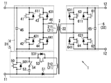
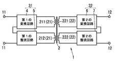
- the power conversion apparatus 1 As shown in FIG. 1, the power conversion apparatus 1 according to the present embodiment is provided between each pair of the first terminal 11 and the second terminal 12 and between the first terminal 11 and the second terminal 12. And a transformer 2. Furthermore, the power conversion device 1 includes a first conversion unit 31 provided between the first terminal 11 and the transformer 2, a second conversion unit 32 provided between the second terminal 12 and the transformer 2, and each unit. And a control unit (not shown) for overall control.
- a control part consists of microcomputers (microcomputer), for example.
- This power conversion device 1 has a function of converting DC power bidirectionally between the first terminal 11 and the second terminal 12, and the first winding 21 and the second winding of the transformer 2. Step-up (or step-down) is performed according to the turn ratio with 22 (that is, the transformation ratio of the transformer 2).
- the control unit controls the operations of the first conversion unit 31 and the second conversion unit 32, so that the direction of power conversion is performed between the first terminal 11 and the second terminal 12. Switch between two different operating modes. That is, the power conversion device 1 converts the DC power from the first terminal 11 into DC power of a desired voltage and outputs it to the second terminal 12, and the DC power from the second terminal 12. Is converted to DC power having a desired voltage and output to the first terminal 11.
- the power conversion device 1 switches the first conversion unit 31 and the second conversion unit 32 to perform PWM (Pulse Width Modulation) control and PPM (Pulse Phase Modulation) control, thereby stepping down at a desired transformation ratio. You can also
- the first terminal 11 is connected to the vehicle side (storage battery)
- the second terminal 12 is connected to the house side (DC supply bus)
- the power conversion device 1 is in the first operation mode when the storage battery is discharged. The case where it operates and operates in the 2nd operation mode at the time of charge of a storage battery is illustrated.
- the transformer 2 two windings of a (first) main winding 211 and a (first) auxiliary winding 212 are provided as the first winding 21 on the primary side (first terminal 11 side).
- a single second winding 22 is provided on the secondary side (second terminal 12 side).
- the number of turns of the main winding 211 is “n1”
- the number of turns of the auxiliary winding 212 is “n2”
- the number of turns of the second winding 22 is “m”.
- the transformer 2 has a turn ratio set so that at least “m> n1”.
- the first converter 31 is provided between the first terminal 11 and the first winding 21.
- the first converter 31 includes a (first) converter circuit 4 connected to the main winding 211, a (first) rectifier circuit 5 connected to the auxiliary winding 212, and a rectifier for the first terminal 11. And a (first) switching unit 50 that switches the connection state of the circuit 5.
- the switching unit 50 is incorporated in the rectifier circuit 5 in the example of FIG. 1, but may be provided separately from the rectifier circuit 5.
- the conversion circuit 4 bi-directionally converts power between the first terminal 11 and the first winding (main winding 211) 21. That is, in the first operation mode, the conversion circuit 4 converts DC power from the first terminal 11, outputs the DC power to the first winding (main winding 211) 21, and supplies power to the second winding 22. . In the second operation mode, the conversion circuit 4 receives power supply from the first winding (main winding 211) 21 and outputs DC power to the first terminal 11. In other words, the conversion circuit 4 functions as an inverter circuit that converts direct current into alternating current in the first operation mode, and functions as a rectifier circuit that converts alternating current into direct current in the second operation mode.
- the conversion circuit 4 includes a (first) capacitor 45, four switching elements 41 to 44 connected between both ends of the capacitor 45, and an inductor 46 as shown in FIG. ing.
- a series circuit of the switching elements 41 and 42 and a series circuit of the switching elements 43 and 44 are connected in parallel, and the conversion circuit 4 constitutes a full bridge type inverter circuit.
- a connection point between the switching elements 41 and 42 and a connection point between the switching elements 43 and 44 are connected to the main winding 211 via an inductor 46.
- the switching elements 41, 42, 43, and 44 are each composed of a MOSFET (Metal / Oxide / Semiconductor / Field / Effect / Transistor) that can be turned on / off by the control unit, and diodes 411, 421, 431, and 441 are anti-parallel between the respective drains and sources. It is connected to the.
- the diodes 411, 421, 431, and 441 may be MOSFET parasitic diodes.
- the switching elements 41, 42, 43, and 44 may be semiconductor switches other than MOSFETs.
- the converter circuit 4 converts the DC voltage across the capacitor 45 into an AC voltage by a switching operation in which the group of switching elements 41 and 44 and the group of switching elements 42 and 43 are alternately turned on. And applied to the first winding (main winding 211) 21.
- the conversion circuit 4 turns off all the switching elements 41 to 44 in the second operation mode, and uses the diode bridge formed of the diodes 411, 421, 431, and 441 as the first rectifier, and the first winding (the main winding 211). )
- the capacitor 45 is charged by receiving power from the power supply 21.
- the AC power from the first winding 21 is full-wave rectified by a diode bridge (first rectifier) including diodes 411, 421, 431, and 441 and smoothed by the capacitor 45.
- the control unit alternately turns on the pair of switching elements 41 and 44 and the pair of switching elements 42 and 43 in the first operation mode, and keeps the switching elements 41 to 44 off in the second operation mode.
- the switching elements 41 to 44 are controlled.
- the rectifier circuit 5 receives power supplied from the first winding (auxiliary winding 212) 21 and outputs DC power to the first terminal 11. In other words, the rectifier circuit 5 functions to convert alternating current into direct current in the second operation mode.
- the rectifier circuit 5 includes a diode 51, a (second) capacitor 52, and a switching element 53 connected in series between both ends of the auxiliary winding 212 as shown in FIG. .
- one end of the auxiliary winding 212 is connected to the cathode of the diode 51
- the other end of the auxiliary winding 212 is connected to one end of the switching element 53
- both ends of the capacitor 52 are connected to the anode of the diode 51 and the switching element 53.
- the switching element 53 is composed of a MOSFET that can be controlled to be turned on and off by a control unit, and a diode 531 is connected in antiparallel between a drain and a source.
- the diode 531 may be a MOSFET parasitic diode.
- the switching element 53 may be a semiconductor switch other than a MOSFET.
- the rectifier circuit 5 is electrically disconnected from the first winding (auxiliary winding 212) 21 by turning off the switching element 53 in the first operation mode, and the auxiliary winding 212 can be regarded as an open state. it can.
- the rectifier circuit 5 receives the power supply from the first winding (auxiliary winding 212) 21 by turning on the switching element 53 in the second operation mode and the diode 51 functioning as the second rectifier.
- the capacitor 52 is charged.
- AC power from the first winding 21 is half-wave rectified by a diode (second rectifier) 51 and smoothed by a capacitor 52 as a smoothing capacitor.
- the control unit controls the switching element 53 such that the switching element 53 is kept off in the first operation mode and the switching element 53 is kept on in the second operation mode.
- the (first) capacitor 45 of the converter circuit 4 and the (second) capacitor 52 of the rectifier circuit 5 are connected in series between the first terminals 11.
- the capacitor 45 is connected to the high potential side and the capacitor 52 is connected to the low potential side.
- the switching unit 50 is a switching element connected in series with the (first) capacitor 45 of the conversion circuit 4 and in parallel with the (second) capacitor 52 of the rectifier circuit 5.
- the switching unit 50 is composed of a MOSFET that can be controlled to be turned on / off by the control unit, and a diode 501 is connected in reverse parallel between the drain and the source.
- the diode 501 may be a parasitic diode of a MOSFET.
- the switching unit 50 may be a semiconductor switch other than a MOSFET.
- both ends of the capacitor 52 are short-circuited by the switching unit 50, and the capacitor 52 of the rectifier circuit 5 is bypassed between the first terminals 11, and the conversion circuit 4 is connected to the first terminal 11.
- the capacitor 45 is connected.
- the switching unit 50 is off, the capacitor 52 of the rectifier circuit 5 is not bypassed, so that the capacitor 45 of the conversion circuit 4 and the capacitor 52 of the rectifier circuit 5 are connected to the first terminal 11.
- the second converter 32 is provided between the second terminal 12 and the second winding 22 and bi-directionally converts power between the second terminal 12 and the second winding 22 (first 2) conversion circuit 6 is provided. That is, the conversion circuit 6 receives the power supply from the second winding 22 in the first operation mode and outputs DC power to the second terminal 12. In the second operation mode, the conversion circuit 6 converts DC power from the second terminal 12, outputs the DC power to the second winding 22, and supplies power to the first winding 21. In other words, the conversion circuit 6 functions as a rectifier circuit that converts alternating current into direct current in the first operation mode, and functions as an inverter circuit that converts direct current into alternating current in the second operation mode.
- the conversion circuit 6 includes a capacitor 65 and four switching elements 61 to 64 connected between both ends of the capacitor 65.
- a series circuit of the switching elements 61 and 62 and a series circuit of the switching elements 63 and 64 are connected in parallel, and the conversion circuit 6 is connected to the first conversion unit 31 ( Similar to the first conversion circuit 4, a full-bridge inverter circuit is configured.
- a connection point between the switching elements 61 and 62 and a connection point between the switching elements 63 and 64 are connected to the second winding 22.
- the switching elements 61, 62, 63, and 64 are formed of MOSFETs that can be controlled to be turned on and off by the control unit, and diodes 611, 621, 631, and 641 are connected in antiparallel between the drains and the sources.
- the diodes 611, 621, 631, and 641 may be MOSFET parasitic diodes.
- the switching elements 61, 62, 63, 64 may be semiconductor switches other than MOSFETs. That is, the (first) conversion circuit 4 of the first conversion unit 31 and the (second) conversion circuit 6 of the second conversion unit 32 are configured substantially symmetrically about the transformer 2.
- the conversion circuit 6 turns off all of the switching elements 61 to 64, and a diode bridge composed of the diodes 611, 621, 631, 641 functions as a third rectifier. Receiving the supply, the capacitor 65 is charged. At this time, the AC power from the second winding 22 is full-wave rectified by a diode bridge (third rectifier) including diodes 611, 621, 631 and 641 and smoothed by the capacitor 65.
- the conversion circuit 6 converts the DC voltage at both ends of the capacitor 65 to AC by switching operation in which the pair of switching elements 61 and 64 and the pair of switching elements 62 and 63 are alternately turned on.
- the voltage is converted and applied to the second winding 22.
- the control unit keeps the switching elements 61 to 64 off in the first operation mode, and alternately turns on the pair of switching elements 61 and 64 and the pair of switching elements 62 and 63 in the second operation mode.
- the switching elements 61 to 64 are controlled.
- the capacitor 65 of the conversion circuit 6 is connected to the second terminal 12. Therefore, in the state where the switching unit 50 is on and the capacitor 45 of the conversion circuit 4 is connected to the first terminal 11 as described above, the power conversion device 1 is connected to the first terminal 11 by the conversion circuits 4 and 6. DC power is converted bidirectionally with the second terminal 12. That is, if the switching unit 50 is fixed in the on state, the power conversion device 1 converts the DC power input from the first terminal 11 into the conversion circuit 4, the transformer 2, and the conversion in the first operation mode. The circuit 6 converts it into DC power having a desired voltage and outputs it from the second terminal 12. In the second operation mode, the power conversion apparatus 1 converts the DC power input from the second terminal 12 into DC power having a desired voltage by the conversion circuit 6, the transformer 2, and the conversion circuit 4. Is output from the terminal 11.
- the transformation ratio between the first terminal 11 and the second terminal 12 in this case is fixedly determined by the turn ratio between the main winding 211 and the second winding 22 of the first winding 21 in the transformer 2. . That is, the ratio between the voltage V1 between the first terminals 11 and the voltage V2 between the second terminals 12 is connected to the number n1 of the main winding 211 connected to the conversion circuit 4 and the conversion circuit 6. It depends on the ratio to the number m of turns of the second winding 22.
- the voltage V1 between the first terminals 11 is a voltage applied between the first terminals 11
- the voltage V2 between the second terminals 12 is a voltage applied between the second terminals 12. .
- the power conversion device 1 when the switching unit 50 is fixed in the ON state, the power conversion device 1 has a relationship of “m> n1” as described above, and therefore the transformation ratio is “V2> V1”. Become a relationship. In other words, in the power conversion device 1, only power conversion from the first terminal 11 to the second terminal 12 (first operation mode) is boosted, and power from the second terminal 12 to the first terminal 11 is increased. The conversion (second operation mode) is step-down.
- the switching unit 50 switches the connection state of the rectifier circuit 5 with respect to the first terminal 11 between the first operation mode and the second operation mode as described below. Bidirectional boosting is possible.
- the switching unit 50 is turned on in the first operation mode to short-circuit both ends of the capacitor 52 of the rectifier circuit 5 and is turned off in the second operation mode. Are switched between the first operation mode and the second operation mode.
- the first converter 31 supplies the DC power from the first terminal 11 to the second converter 32 through the converter circuit 4 and the transformer 2 in the first operation mode, and the converter circuit 4 in the second operation mode.
- a voltage obtained by adding the output voltage of the rectifier circuit 5 to the output voltage is output to the first terminal 11.
- FIGS. 2A and 2B Note that arrow A in FIG. 2A and arrow B in FIG. 2B indicate the direction of power conversion.
- the power conversion device 1 is configured such that, in the first operation mode in which power conversion is performed from the first terminal 11 to the second terminal 12, the switching unit 50 is turned on so that the first terminal 11 is connected to the capacitor 45 of the conversion circuit 4. At this time, the input current I1 from the first terminal 11 flows through the switching unit 50 and does not flow into the capacitor 52 of the rectifier circuit 5. Therefore, if the ON resistance of the switching unit 50 is negligible, a voltage having the same magnitude as the voltage V1 between the first terminals 11 is applied to the capacitor 45 of the conversion circuit 4. 2A, since the switching element 53 is turned off and the rectifier circuit 5 is electrically disconnected from the first winding (auxiliary winding 212) 21, the auxiliary winding 212 of the first winding 21 is It becomes an open state.
- the power conversion device 1 has the first terminal at a transformation ratio determined by the turns ratio (n1: m) between the main winding 211 and the second winding 22 of the first winding 21. 11 converts the DC power from 11 and outputs it to the second terminal 12.
- the turn ratio is in a relationship of “m> n1”
- the switching unit 50 in the power conversion device 1, in the second operation mode in which power conversion from the second terminal 12 to the first terminal 11 is performed, the switching unit 50 is turned off. At this time, in the rectifier circuit 5, the switching element 53 is turned on, and the diode 51 functions as the second rectifier, so that the current (half wave) I2 from the first winding (auxiliary winding 212) 21 is a capacitor. Then, the capacitor 52 is charged. Therefore, in the state of FIG. 2B, the voltage V1 between the first terminals 11 is a voltage obtained by adding the voltage V12 across the capacitor 52 to the voltage V11 across the capacitor 45.
- the ratio between the output voltage V11 of the conversion circuit 4 and the voltage V2 between the second terminals 12 is determined by the turn ratio (n1: m) between the main winding 211 and the second winding 22, and the conversion circuit. 4 output voltage V11 is represented by “V2 ⁇ n1 / m”. Further, the ratio between the output voltage V12 of the rectifier circuit 5 and the voltage V2 between the second terminals 12 is similarly determined by the turn ratio (n2: m) between the auxiliary winding 212 and the second winding 22, and the rectifier circuit. Assume that an output voltage V12 of 5 is represented by “V2 ⁇ n2 / m”. That is, it is assumed that the ratio “V11: V12” between the voltage V11 across the capacitor 45 and the voltage V12 across the capacitor 52 is represented by “n1: n2”.
- the conversion circuit 4 performs full-wave rectification, whereas the rectification circuit 5 performs half-wave rectification, so that the output voltage V11 of the conversion circuit 4 is not necessarily “V2 ⁇ n1 / m” as described above.
- the output voltage V12 of the rectifier circuit 5 is not always represented by “V2 ⁇ n2 / m”. However, for example, by adjusting the capacitance of the capacitor 45 of the conversion circuit 4 and the capacitor 52 of the rectifier circuit 5 or by making the rectifier circuit 5 a full-wave rectifier circuit, the output voltage V12 of the rectifier circuit 5 is set to “V2 ⁇ n2 / m ”is possible.
- the switching unit 50 switches the connection state of the rectifier circuit 5 to the first terminal 11 between the first operation mode and the second operation mode, so that the bidirectional Boosting is possible. That is, the first converter 31 supplies the DC power from the first terminal 11 to the second converter 32 through the converter circuit 4 and the transformer 2 in the first operation mode, and the output of the converter circuit 4 in the second operation mode. A voltage obtained by adding the output voltage of the rectifier circuit 5 to the voltage is output to the first terminal 11. Therefore, the power conversion device 1 converts power from the first terminal 11 to the second terminal 12 (first operation mode) and converts power from the second terminal 12 to the first terminal 11 (second operation). In both cases, the voltage can be boosted.
- the power conversion device 1 When the storage battery is discharged (first operation mode), the power conversion device 1 boosts the DC power input from the vehicle side (storage battery) to the first terminal 11 to the residential side from the second terminal 12. Can output to (DC supply bus). On the other hand, when the storage battery is charged (second operation mode), the power conversion device 1 boosts the DC power input from the house side (DC supply bus) to the second terminal 12 to increase the first power. It can output from the terminal 11 to the vehicle side (storage battery).
- the operation of the power converter 1 when the input / output voltage range on the vehicle side is 100 to 500 VDC and the input / output voltage range on the house side is 300 to 400 VDC will be described.
- the power conversion device 1 boosts the direct current 100V input to the first terminal 11 to the direct current 300V and outputs it from the second terminal 12 when the storage battery is discharged, and outputs the second terminal 12 when charging the storage battery.
- DC 300V input to 12 is boosted to 500V and output from the first terminal 11.
- the first terminal 11 may be connected to the house side
- the second terminal 12 may be connected to the vehicle side
- the input / output voltage ranges on the vehicle side and the house side are also described above. It is not limited to the value.
- the rectifier circuit 5 is inserted between the (second) capacitor 52 and the switching unit 50 (first )
- a switch 54 may be provided.
- the switch 54 is inserted between the connection point between the switching unit 50 and the switching element 53 and the capacitor 52, and is controlled to be turned on and off by the control unit.
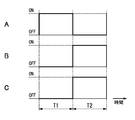
- FIG. 4A to 4C are timing charts showing operations of the switching unit 50, the switching element 53, and the switch 54 in the example of FIG. 4A represents the on / off state of the switching unit 50, FIG. 4B represents the on / off state of the switching element 53, and FIG. 4C represents the on / off state of the switch 54.
- the rectifier circuit 5 turns off the switch 54 and switches the capacitor 52 in the first operation mode (period T1) in which the switching unit 50 is on and the switching element 53 is off. Electrically disconnected from 50. As shown in FIGS. 4A to 4C, the rectifier circuit 5 turns on the switch 54 and turns on the capacitor 52 in the first operation mode (period T2) in which the switching unit 50 is off and the switching element 53 is on. The voltage across the capacitor 52 is output to the first terminal 11.
- the switch unit 50 when switching from the second operation mode to the first operation mode, the switch unit 50 is turned on and the switch 54 is turned off at the same time. 50 can be avoided. Therefore, the power conversion device 1 can prevent the circuit element from being stressed by a large current flowing from the capacitor 52 to the switching unit 50.
- the switch 54 for separating the capacitor 52 from the switching unit 50 may be provided at a position as shown in FIG.
- the power conversion device 1 includes a switch 54 between the connection point of the capacitor 45 and the capacitor 52 and the connection point of the switching element 42 and the switching unit 50.
- the rectifier circuit 5 turns off the switch 54 and electrically disconnects the capacitor 52 from the switching unit 50.
- the rectifier circuit 5 turns on the switch 54 to connect the capacitor 52 to the switching element 53 and supply power from the auxiliary winding 212.
- the capacitor 52 is charged.
- the power conversion device 1 (first) according to the turn ratio (n1: n2) between the main winding 211 and the auxiliary winding 212. It is desirable that the capacitances of the capacitor 45 and the (second) capacitor 52 are determined.
- the turn ratio “n1: n2” between the main winding 211 and the auxiliary winding 212 is “3: 1”
- the voltage across the capacitor 45 in the second operation mode is 300 V
- the ratio “C1: C2” between the capacitance C1 of the capacitor 45 and the capacitance C2 of the capacitor 52 is preferably “1: 3”. That is, the capacitance of the capacitor 45 and the capacitor 52 is determined according to the turn ratio (n1: n2) between the main winding 211 and the auxiliary winding 212 so that the charge amount in the second operation mode is the same. .
- the output voltage of the conversion circuit 4 is equal to the voltage across the capacitor 45 when the switch 54 is switched on and off.
- the output voltage of the rectifier circuit 5 matches the voltage across the capacitor 52.
- the specific configurations of the conversion circuit 4 and the rectifier circuit 5 in the first conversion unit 31 and the conversion circuit 6 in the second conversion unit 32 described in the present embodiment are not limited to the above-described configurations, and can be changed as appropriate.
- the rectifier circuit 5 may be a full-wave rectifier circuit using a diode bridge instead of the half-wave rectifier circuit as described above.
- the conversion circuit 4 rectifies by switching operation of the switching elements 41 to 44, for example, instead of a configuration in which all the switching elements 41 to 44 are turned off and rectified by the diode bridge. It may be a configuration.
- the conversion circuit 4 converts the alternating current power from the main winding 211 into direct current power by a switching operation in which the pair of switching elements 41 and 44 and the pair of switching elements 42 and 43 are alternately turned on, thereby converting the capacitor. 45 can be applied. The same applies to the conversion circuit 6.
- the transformer 2 is not limited to the configuration in which the first winding 21 is composed of two windings of the main winding 211 and the auxiliary winding 212, and the first winding 21 may be configured to be composed of one winding.
- the first converter 31 is configured by connecting the converter circuit 4 and the rectifier circuit 5 in parallel between both ends of the first winding 21.
- the transformer 2 divides the core into a first core provided with the first winding 21 and a second core provided with the second winding 22, whereby the first winding 21 and the first winding 21 are divided.
- segment 2 windings 22 may be sufficient.
- the power converter 1 can physically separate the first converter 31 and the second converter 32, and magnetically couples the core of the transformer 2 only when the storage battery is charged or discharged. Thus, the power can be exchanged between the first conversion unit 31 and the second conversion unit 32.
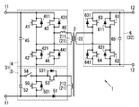
- Embodiment 2 In the power conversion device 1 of the present embodiment, the conversion circuit 4 and the rectifier circuit 5 in the first conversion unit 31 are arranged in such a manner that ripples (pulsations) generated in the output voltage in the second operation mode are in opposite phases. 1 is different from the power conversion device 1 of the first embodiment in that it is connected to the terminal 11 of the first embodiment.
- the same configurations as those of the first embodiment are denoted by common reference numerals, and description thereof is omitted as appropriate.
- the rectifier circuit 5 and the conversion circuit 4 have the first terminal 11 so that the ripple generated in the output voltage of the rectifier circuit 5 and the ripple generated in the output voltage of the conversion circuit 4 are in opposite phases in the second operation mode. It is connected to the.
- the power conversion device 1 is configured such that the winding direction is reversed between the main winding 211 and the auxiliary winding 212 of the transformer 2 as shown in FIG.
- the conversion circuit 4 connected to the main winding 211 is configured to perform half-wave rectification similarly to the rectification circuit 5 in the second operation mode.
- arrow B represents the direction of power conversion, and the voltage waveform at each part is illustrated.
- the ripple component superimposed on the output voltage of the conversion circuit 4 is out of phase with the ripple component superimposed on the output voltage of the rectifier circuit 5 in the second operation mode. Offset. Therefore, the power conversion device 1 makes the ripple component from the first terminal 11 in the second operation mode while the capacitors 45 and 52 (see FIG. 1) of the conversion circuit 4 and the rectifier circuit 5 have relatively small capacities. A small DC voltage can be output. As a result, there is an advantage that the capacitors 45 and 52 are reduced in size and cost.
- the configuration for making the ripples generated in the output voltage in the conversion circuit 4 and the rectifier circuit 5 in opposite phases is such that the winding direction is reversed between the main winding 211 and the auxiliary winding 212 as described above. It is not limited to the configuration.
- the conversion circuit 4 has a configuration in which AC power from the main winding 211 is half-wave rectified by the switching operation of the switching elements 41 to 44 so that the output to the first terminal 11 has a phase opposite to that of the rectifier circuit 5. There may be.
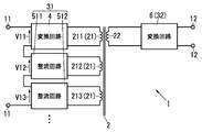
- the power conversion device 1 As shown in FIG. 7, the power conversion device 1 according to the present embodiment includes the plurality of rectifier circuits 511, 512,. Is different.
- the same configurations as those of the first embodiment are denoted by common reference numerals, and description thereof is omitted as appropriate.
- the switching unit 50 switches the connection state of the plurality of rectifier circuits 511, 512,... To the first terminal 11 between the first operation mode and the second operation mode.
- the first converter 31 outputs the output voltage of at least one rectifier circuit 511, 512,.
- the voltage added to the voltage is output to the first terminal 11.
- the switching unit 50 is connected between both ends of the capacitor 52 (see FIG. 1) of each rectifier circuit 511, 512,..., And in the first operation mode, all the rectifier circuits 511, 512,. .. Short-circuit between both ends of the capacitor 52.
- the second operation mode when at least one switching unit 50 is turned off, the output voltages V12, V13,... Of the rectifier circuits 511, 512,. At least one is added and output to the first terminal 11.
- the first terminal 11 in the second operation mode is connected to the conversion circuit 4 by connecting a plurality of rectifier circuits 511, 512,.
- the output voltage from can be switched in multiple stages.
- the power conversion device 1 As shown in FIG. 8, the power conversion device 1 according to the present embodiment is configured such that the second conversion unit 32 is configured to be symmetrical with the first conversion unit 31 with the transformer 2 as the center. This is different from the power conversion device 1.
- the same configurations as those of the first embodiment are denoted by common reference numerals, and description thereof is omitted as appropriate.
- the transformer 2 includes a second winding of a (second) main winding 221 and a (second) auxiliary winding 222 on the secondary side (second terminal 12 side). It is provided as a line 22.
- the second conversion unit 32 includes the (second) rectifier circuit 7 connected to the auxiliary winding 222 and the second terminal 12 in addition to the (second) conversion circuit 6 connected to the main winding 221. And a second switching unit (not shown) for switching the connection state of the rectifier circuit 7 to the.
- the conversion circuit 6 bi-directionally converts power between the second terminal 12 and the second winding (main winding 221) 22.
- the rectifier circuit 7 receives power supply from the second winding (auxiliary winding 222) 22 and outputs DC power.
- the second switching unit is incorporated in the rectifier circuit 7, but may be provided separately from the rectifier circuit 7. If the second terminal 12 is replaced with the first terminal 11 and the second winding 22 is replaced with the first winding 21, the conversion circuit 6 in the second conversion unit 32 corresponds to the conversion circuit 4 in the first conversion unit 31.
- the rectifier circuit 7 in the second converter 32 corresponds to the rectifier circuit 5 in the first converter 31.
- the conversion circuit 6 has a third rectifier (not shown) connected to the main winding 221 and a third capacitor (not shown) connected to the DC output of the third rectifier.
- the rectifier circuit 7 includes a fourth rectifier (not shown) connected to the auxiliary winding 222 and a fourth capacitor (not shown) connected to the DC output of the fourth rectifier.
- the third capacitor and the fourth capacitor are connected in series to the second terminal 12.
- the third rectifier corresponds to the first rectifier of the conversion circuit 4 (diodes 411, 421, 431, and 441 in FIG. 1), and the third capacitor corresponds to the (first) capacitor 45 of the conversion circuit 4.
- the fourth rectifier corresponds to the second rectifier (diode 51 in FIG. 1) of the rectifier circuit 5, and the fourth capacitor corresponds to the (second) capacitor 52 of the rectifier circuit 5. Therefore, illustration and detailed description of each component of the conversion circuit 6 and the rectifier circuit 7 are omitted here.
- the second switching unit corresponds to the (first) switching unit 50 in the first conversion unit 31. That is, the second switching unit includes a switching element connected between both ends of the fourth capacitor.
- the second switching unit is turned on in the second operation mode to short-circuit both ends of the fourth capacitor of the rectifier circuit 7 and is turned off in the first operation mode.
- the connection state is switched between the first operation mode and the second operation mode.
- the second converter 32 supplies the DC power from the second terminal 12 to the first converter 31 through the converter circuit 6 and the transformer 2 in the second operation mode, and the converter circuit 6 in the first operation mode.
- a voltage obtained by adding the output voltage of the rectifier circuit 7 to the output voltage is output to the second terminal 12.
- the first terminal 11 -second the first terminal 11 -second
- the step-up ratio between the terminals 12 can be matched in both directions.
- the power conversion device 1 includes a rectifier circuit 7 having a second switch (not shown) inserted between the fourth capacitor and the second switching unit. It may be.
- the second switch corresponds to the switch 54 of the modification of the first embodiment shown in FIG. Therefore, illustration and detailed description of the second switch are omitted here.
- the rectifier circuit 7 includes the second switch, the third capacitor and the fourth capacitor have the same amount of charge in the first operation mode so that the main winding 221 and the auxiliary winding 222 have the same amount of charge.
- the capacity may be determined according to the turn ratio.
- the configuration of the fourth embodiment (the second conversion unit 32 is symmetric with the first conversion unit 31) is appropriately combined with each configuration described in the first embodiment and each configuration described in the second and third embodiments. Can do.
- the conversion circuit 6 and the rectifier circuit 7 in the second conversion unit 32 have a ripple (pulsating flow) generated in the output voltage in the first operation mode.
- the second terminals 12 are connected so as to be in opposite phases.
- the second conversion unit 32 includes a plurality of second rectifier circuits.
- the second switching unit switches the connection state of the plurality of second rectifier circuits with respect to the second terminal 12 between the first operation mode and the second operation mode.
- the second conversion unit 32 adds a voltage obtained by adding the output voltage of at least one second rectifier circuit to the output voltage of the converter circuit 6 among the plurality of second rectifier circuits. Output to the second terminal 12.
- the power converter device 1 used for charge and discharge of the storage battery of a vehicle was illustrated, the power converter device 1 may be used for other uses, for example, other than charge and discharge of a storage battery May be used.
Abstract
This electric power conversion device (1) has a first operation mode in which direct-current power from first terminals (11) is converted into direct-current power of a desired voltage and output to second terminals (12) and a second operation mode in which direct-current power from the second terminals (12) is converted into direct-current power of a desired voltage and output to the first terminals (11). A switching part (50) is turned on so as to short-circuit a capacitor (52) of a rectification circuit (5) in the first operation mode, and is turned off in the second operation mode. Consequently, a first conversion unit (31) supplies the direct-current power from the first terminals (11) to a second conversion unit (32) from a first winding wire (21) via a conversion circuit (4) in the first operation mode, and outputs a voltage, which is obtained by adding an output voltage of the rectification circuit (5) to an output voltage of the conversion circuit (4), to the first terminals (11) in the second operation mode. Thus, bi-directional voltage boosting is enabled in spite of the use of a transformer.
Description
本発明は、トランスを用いて双方向に直流電力を変換する電力変換装置に関する。
The present invention relates to a power conversion device that converts DC power bidirectionally using a transformer.
従来から、一次側と二次側との間で双方向に直流電力を変換する電力変換装置が、蓄電池の充電および放電などに用いられている。たとえば、電力変換装置は、一次側に直流電源、二次側に蓄電池が接続された状態で、直流電源からの直流電力を所望の直流電力に変換し二次側に出力することにより、蓄電池を充電することができる。また、電力変換装置は、一次側に負荷、二次側に蓄電池が接続された状態で、蓄電池からの直流電力を所望の直流電力に変換し一次側に出力することにより、蓄電池を放電することができる。
Conventionally, power converters that convert DC power bidirectionally between a primary side and a secondary side have been used for charging and discharging storage batteries. For example, a power conversion device converts a DC power from a DC power source into a desired DC power and outputs it to the secondary side with a DC power source connected to the primary side and a storage battery connected to the secondary side. Can be charged. Also, the power conversion device discharges the storage battery by converting the DC power from the storage battery to the desired DC power and outputting it to the primary side with the load connected to the primary side and the storage battery connected to the secondary side. Can do.
この種の電力変換装置としては、第1の直流電源または第1の負荷と、第2の負荷または第2の直流電源との間で相互に直流変換機能を有する装置(双方向DC/DCコンバータ)が知られている(文献1:日本国公開特許公報第2011-234541号参照)。文献1に記載の電力変換装置は、第1の直流電源または第1の負荷を含む一次側回路と、第2の負荷または第2の直流電源を含む二次側回路と、一次側回路と二次側回路との間に設けられたトランスとを備えている。
As this type of power conversion device, a device (bidirectional DC / DC converter) having a mutual DC conversion function between a first DC power source or first load and a second load or second DC power source. (Reference 1: Japanese Published Patent Publication No. 2011-234541). The power conversion device described in Literature 1 includes a primary side circuit including a first DC power source or a first load, a secondary side circuit including a second load or a second DC power source, a primary side circuit, and a second side circuit. And a transformer provided between the secondary circuit and the secondary circuit.
また、文献1に記載の電力変換装置は、一次側回路と二次側回路との各々に、4個の半導体スイッチにより構成されるブリッジ回路を備えている。この電力変換装置は、両ブリッジ回路の半導体スイッチの動作を同期させることにより、一次側回路から二次側回路へトランスの変圧比で変圧された電力を供給し、また、二次側回路から一次側回路へトランスの変圧比で変圧された電力を供給する。
In addition, the power conversion device described in Document 1 includes a bridge circuit configured by four semiconductor switches in each of the primary side circuit and the secondary side circuit. This power converter supplies power transformed by the transformer transformation ratio from the primary side circuit to the secondary side circuit by synchronizing the operations of the semiconductor switches of both bridge circuits, and also from the secondary side circuit. Supply power transformed at the transformer transformation ratio to the side circuit.
しかし、トランスを用いて双方向に直流電力を変換する電力変換装置は、トランスの変圧比(巻数比)によって、昇圧の向きが固定されており、双方向に昇圧することができない。つまり、一次側から二次側への電力変換が昇圧になる構成の電力変換装置であれば、逆向き(二次側から一次側)への電力変換は降圧になる。そのため、この電力変換装置は、たとえば蓄電池の充電および放電に用いられる場合に、蓄電池の充電時には直流電源からの直流電力を昇圧して蓄電池を充電し、蓄電池の放電時には蓄電池からの直流電力を昇圧して負荷に供給するという使い方ができない。
However, in a power conversion device that converts DC power bidirectionally using a transformer, the direction of boosting is fixed by the transformer's transformation ratio (turn ratio), so that boosting in both directions is not possible. That is, if the power conversion device has a configuration in which power conversion from the primary side to the secondary side is boosted, power conversion in the reverse direction (secondary side to primary side) is stepped down. Therefore, for example, when this power conversion device is used for charging and discharging a storage battery, it boosts the DC power from the DC power source when charging the storage battery to charge the storage battery, and boosts the DC power from the storage battery when discharging the storage battery. And cannot be used to supply the load.
本発明は上記事由に鑑みて為されており、トランスを用いながらも双方向に昇圧可能な電力変換装置を提供することを目的とする。
The present invention has been made in view of the above reasons, and an object thereof is to provide a power conversion device capable of boosting in both directions while using a transformer.
本発明に係る第1の形態の電力変換装置は、第1の端子と第2の端子との間に設けられたトランスと、前記第1の端子と前記トランスの第1巻線との間に設けられた第1変換部と、前記第2の端子と前記トランスの第2巻線との間に設けられた第2変換部とを備え、前記第1の端子からの直流電力を所望の電圧の直流電力に変換して前記第2の端子に出力する第1動作モードと、前記第2の端子からの直流電力を所望の電圧の直流電力に変換して前記第1の端子に出力する第2動作モードとを有する電力変換装置であって、前記第1変換部は、前記第1の端子と前記第1巻線との間で双方向に電力変換する第1の変換回路と、前記第1巻線から電力供給を受けて直流電力を出力する第1の整流回路と、前記第1の端子に対する前記第1の整流回路の接続状態を前記第1動作モードと前記第2動作モードとで切り替える第1の切替部とを有し、前記第1の切替部にて前記接続状態を切り替えることによって、前記第1動作モードでは前記第1の端子からの直流電力を前記第1の変換回路および前記トランスを通して前記第2変換部に供給し、前記第2動作モードでは前記第1の変換回路の出力電圧に前記第1の整流回路の出力電圧を加算した電圧を前記第1の端子に出力するように構成されている。
According to a first aspect of the present invention, there is provided a power conversion device including a transformer provided between a first terminal and a second terminal, and between the first terminal and the first winding of the transformer. A first conversion unit provided; and a second conversion unit provided between the second terminal and the second winding of the transformer, the direct current power from the first terminal being a desired voltage A first operation mode in which the direct current power is converted and output to the second terminal, and direct current power from the second terminal is converted into direct current power of a desired voltage and output to the first terminal. A power conversion device having two operation modes, wherein the first conversion unit includes a first conversion circuit that performs bidirectional power conversion between the first terminal and the first winding; A first rectifier circuit that receives power supply from one winding and outputs DC power; and the first rectifier for the first terminal. A first switching unit that switches a circuit connection state between the first operation mode and the second operation mode, and the first operation mode is switched by switching the connection state in the first switching unit; Then, DC power from the first terminal is supplied to the second conversion unit through the first conversion circuit and the transformer, and the output voltage of the first conversion circuit is supplied to the first conversion circuit in the second operation mode. A voltage obtained by adding the output voltages of the rectifier circuit is output to the first terminal.
この形態によれば、電力変換装置は、第1の端子に対する第1の整流回路の接続状態を第1の切替部にて第1動作モードと第2動作モードとで切り替える。これにより、第1変換部は、第1動作モードでは第1の端子からの直流電力を第1の変換回路およびトランスを通して第2変換部に供給し、第2動作モードでは第1の変換回路の出力電圧に第1の整流回路の出力電圧を加算した電圧を前記第1の端子に出力する。したがって、トランスを用いながらも双方向に昇圧可能という利点がある。
According to this aspect, the power conversion device switches the connection state of the first rectifier circuit with respect to the first terminal between the first operation mode and the second operation mode at the first switching unit. As a result, the first converter supplies DC power from the first terminal to the second converter through the first converter circuit and the transformer in the first operation mode, and the first converter circuit in the second operation mode. A voltage obtained by adding the output voltage of the first rectifier circuit to the output voltage is output to the first terminal. Therefore, there is an advantage that the voltage can be boosted in both directions while using a transformer.
本発明に係る第2の形態の電力変換装置では、第1の形態において、前記トランスは、前記第1の変換回路に接続される第1の主巻線と前記第1の整流回路に接続される第1の補助巻線とを前記第1巻線として有する。
In the power converter of the second mode according to the present invention, in the first mode, the transformer is connected to the first main winding connected to the first converter circuit and the first rectifier circuit. And the first auxiliary winding as the first winding.
本発明に係る第3の形態の電力変換装置では、第2の形態において、前記第1の変換回路は、前記第1の主巻線に接続される第1の整流器と、前記第1の整流器の直流出力に接続される第1のコンデンサとを有し、前記第1の整流回路は、前記第1の補助巻線に接続される第2の整流器と、前記第2の整流器の直流出力に接続される第2のコンデンサとを有し、前記第1のコンデンサと前記第2のコンデンサとは前記第1の端子に対して直列接続されており、前記第1の切替部は、前記第2のコンデンサの両端間に接続されたスイッチング素子からなり、前記第1動作モードではオンすることで前記第2のコンデンサの両端間を短絡し、前記第2動作モードではオフするように構成されている。
In the power converter of the third mode according to the present invention, in the second mode, the first converter circuit includes a first rectifier connected to the first main winding, and the first rectifier. A first capacitor connected to the direct current output of the second rectifier, and the first rectifier circuit is connected to the second rectifier connected to the first auxiliary winding and to the direct current output of the second rectifier. A second capacitor to be connected, wherein the first capacitor and the second capacitor are connected in series to the first terminal, and the first switching unit includes the second capacitor The switching element is connected between both ends of the capacitor, and is configured to be short-circuited between both ends of the second capacitor by being turned on in the first operation mode and to be turned off in the second operation mode. .
本発明に係る第4の形態の電力変換装置では、第3の形態において、前記第1の整流回路は、前記第2のコンデンサと前記第1の切替部との間に挿入され、前記第1動作モードでオフし、前記第2動作モードでオンする第1のスイッチを有する。
In the power converter of the 4th form concerning the present invention, in the 3rd form, the 1st rectifier circuit is inserted between the 2nd capacitor and the 1st change part, and the 1st A first switch that is turned off in the operation mode and turned on in the second operation mode;
本発明に係る第5の形態の電力変換装置では、第4の形態において、前記第1のコンデンサと前記第2のコンデンサとは、前記第2動作モードでの電荷量が同じになるように、前記第1の主巻線と前記第1の補助巻線との巻数比に応じて容量が決められている。
In the power converter of the fifth aspect according to the present invention, in the fourth aspect, the first capacitor and the second capacitor have the same charge amount in the second operation mode. The capacity is determined in accordance with the turn ratio between the first main winding and the first auxiliary winding.
本発明に係る第6の形態の電力変換装置では、第1~5のいずれかの形態において、前記第1の整流回路および前記第1の変換回路は、前記第2動作モードにおいて前記第1の整流回路の出力電圧に生じるリップルと前記第1の変換回路の出力電圧に生じるリップルとが互いに逆相になるように、前記第1の端子に接続されている。
In the power converter of the sixth aspect according to the present invention, in any one of the first to fifth aspects, the first rectifier circuit and the first converter circuit are the first operation circuit in the second operation mode. The ripple generated in the output voltage of the rectifier circuit and the ripple generated in the output voltage of the first conversion circuit are connected to the first terminal so as to have opposite phases.
本発明に係る第7の形態の電力変換装置では、第1~6のいずれかの形態において、前記第1変換部は、前記第1の整流回路を複数有しており、前記第1の切替部が前記第1の端子に対する前記複数の前記第1の整流回路の接続状態を切り替えることによって、前記第2動作モードでは、前記複数の前記第1の整流回路のうち少なくとも1つの前記第1の整流回路の出力電圧を前記第1の変換回路の出力電圧に加算した電圧を前記第1の端子に出力するように構成されている。
In the power converter of the seventh aspect according to the present invention, in any one of the first to sixth aspects, the first converter has a plurality of the first rectifier circuits, and the first switching unit In the second operation mode, the unit switches the connection state of the plurality of first rectifier circuits to the first terminal, so that at least one of the plurality of first rectifier circuits is the first first rectifier circuit. A voltage obtained by adding the output voltage of the rectifier circuit to the output voltage of the first conversion circuit is output to the first terminal.
本発明に係る第8の形態の電力変換装置では、第1~7のいずれかの形態において、前記第2変換部は、前記第2の端子と前記第2巻線との間で双方向に電力変換する第2の変換回路と、前記第2巻線から電力供給を受けて直流電力を出力する第2の整流回路と、前記第2の端子に対する前記第2の整流回路の接続状態を前記第1動作モードと前記第2動作モードとで切り替える第2の切替部とを有し、前記第2の切替部にて前記接続状態を切り替えることによって、前記第2動作モードでは前記第2の端子からの直流電力を前記第2の変換回路および前記トランスを通して前記第1変換部に供給し、前記第1動作モードでは前記第2の変換回路の出力電圧に前記第2の整流回路の出力電圧を加算した電圧を前記第2の端子に出力するように構成されている。
In the power converter of the eighth aspect according to the present invention, in any one of the first to seventh aspects, the second converter is bidirectional between the second terminal and the second winding. A second conversion circuit for power conversion, a second rectification circuit for receiving DC power supplied from the second winding and outputting DC power, and a connection state of the second rectification circuit to the second terminal A second switching unit that switches between the first operation mode and the second operation mode, and the second terminal in the second operation mode by switching the connection state in the second switching unit. Is supplied to the first converter through the second converter circuit and the transformer, and the output voltage of the second rectifier circuit is supplied to the output voltage of the second converter circuit in the first operation mode. Output the added voltage to the second terminal It is configured.
本発明に係る第9の形態の電力変換装置では、第8の形態において、前記トランスは、前記第2の変換回路に接続される第2の主巻線と前記第2の整流回路に接続される第2の補助巻線とを前記第2巻線として有する。
In a power converter of a ninth aspect according to the present invention, in the eighth aspect, the transformer is connected to a second main winding connected to the second converter circuit and the second rectifier circuit. And the second auxiliary winding as the second winding.
本発明に係る第10の形態の電力変換装置では、第9の形態において、前記第2の変換回路は、前記第2の主巻線に接続される第3の整流器と、前記第3の整流器の直流出力に接続される第3のコンデンサとを有し、前記第2の整流回路は、前記第2の補助巻線に接続される第4の整流器と、前記第4の整流器の直流出力に接続される第4のコンデンサとを有し、前記第3のコンデンサと前記第4のコンデンサとは前記第2の端子に対して直列接続されており、前記第2の切替部は、前記第4のコンデンサの両端間に接続されたスイッチング素子からなり、前記第2動作モードではオンすることで前記第4のコンデンサの両端間を短絡し、前記第1動作モードではオフするように構成されている。
According to a tenth aspect of the power conversion device of the present invention, in the ninth aspect, the second conversion circuit includes a third rectifier connected to the second main winding, and the third rectifier. A third capacitor connected to the DC output of the second rectifier, and the second rectifier circuit is connected to the fourth rectifier connected to the second auxiliary winding and to the DC output of the fourth rectifier. A fourth capacitor to be connected, wherein the third capacitor and the fourth capacitor are connected in series to the second terminal, and the second switching unit includes the fourth capacitor The switching element is connected between both ends of the capacitor, and is configured to be short-circuited between both ends of the fourth capacitor by being turned on in the second operation mode and to be turned off in the first operation mode. .
本発明に係る第11の形態の電力変換装置では、第10の形態において、前記第2の整流回路は、前記第4のコンデンサと前記第2の切替部との間に挿入され、前記第2動作モードでオフし、前記第1動作モードでオンする第2のスイッチを有する。
According to an eleventh aspect of the power conversion device of the present invention, in the tenth aspect, the second rectifier circuit is inserted between the fourth capacitor and the second switching unit, and the second A second switch that is turned off in the operation mode and turned on in the first operation mode;
本発明に係る第12の形態の電力変換装置では、第11の形態において、前記第3のコンデンサと前記第4のコンデンサとは、前記第1動作モードでの電荷量が同じになるように、前記第2の主巻線と前記第2の補助巻線との巻数比に応じて容量が決められている。
In a power converter according to a twelfth aspect of the present invention, in the eleventh aspect, the third capacitor and the fourth capacitor have the same charge amount in the first operation mode. The capacity is determined in accordance with the turn ratio between the second main winding and the second auxiliary winding.
本発明に係る第13の形態の電力変換装置では、第8~12のいずれかの形態において、前記第2の整流回路および前記第2の変換回路は、前記第1動作モードにおいて前記第2の整流回路の出力電圧に生じるリップルと前記第2の変換回路の出力電圧に生じるリップルとが互いに逆相になるように、前記第2の端子に接続されている。
In the power converter of the thirteenth aspect according to the present invention, in any one of the eighth to twelfth aspects, the second rectifier circuit and the second converter circuit are the second converter circuit in the first operation mode. The ripple generated in the output voltage of the rectifier circuit and the ripple generated in the output voltage of the second conversion circuit are connected to the second terminal so that the phases are opposite to each other.
本発明に係る第14の形態の電力変換装置では、第8~13のいずれかの形態において、前記第2変換部は、前記第2の整流回路を複数有しており、前記第2の切替部が前記第2の端子に対する前記複数の前記第2の整流回路の接続状態を切り替えることによって、前記第1動作モードでは、前記複数の前記第2の整流回路のうち少なくとも1つの前記第2の整流回路の出力電圧を前記第2の変換回路の出力電圧に加算した電圧を前記第2の端子に出力するように構成されている。
In the power converter of the fourteenth aspect according to the present invention, in any one of the eighth to thirteenth aspects, the second converter has a plurality of the second rectifier circuits, and the second switching In the first operation mode, the unit switches the connection state of the plurality of second rectifier circuits to the second terminal, so that at least one of the plurality of second rectifier circuits is the second A voltage obtained by adding the output voltage of the rectifier circuit to the output voltage of the second conversion circuit is output to the second terminal.
(実施形態1)
本実施形態では、電力変換装置として、電気自動車(EV)やプラグインハイブリッド車(PHEV)など、電気エネルギを用いて走行時の駆動力を発生する車両に搭載されている蓄電池(走行用バッテリ)の充電および放電に用いられる電力変換装置を例示する。なお、車両は、蓄電池に蓄電された電気エネルギを走行に用いる電動車両であればよく、四輪自動車に限らず電動二輪車などであってもよい。 (Embodiment 1)
In this embodiment, as a power conversion device, a storage battery (traveling battery) mounted on a vehicle that generates driving force during traveling using electric energy, such as an electric vehicle (EV) or a plug-in hybrid vehicle (PHEV). The power converter device used for charge and discharge of is illustrated. The vehicle may be an electric vehicle that uses electric energy stored in the storage battery for traveling, and is not limited to a four-wheeled vehicle but may be an electric two-wheeled vehicle.
以下に説明する電力変換装置は、住宅に設置され、住宅に設けられている直流供給バス(図示せず)から車両(図示せず)に電力供給して車両の蓄電池(図示せず)を充電し、また、車両の蓄電池を放電させて直流供給バスに電力供給を行うのに用いられる。ここでいう直流供給バスは、太陽光発電装置や燃料電池や据置型の蓄電装置などの直流電源に接続され、これらの直流電源からの直流電力をパワーコンディショナ等に供給する。なお、本実施形態では、電力変換装置が戸建て住宅に用いられる場合について説明するが、戸建て住宅に限らず、集合住宅や事業所などに電力変換装置が用いられていてもよい。
A power conversion device described below is installed in a house and supplies power to a vehicle (not shown) from a DC supply bus (not shown) provided in the house to charge a storage battery (not shown) of the vehicle. In addition, it is used to supply power to the DC supply bus by discharging the storage battery of the vehicle. The DC supply bus here is connected to a DC power source such as a solar power generation device, a fuel cell, or a stationary power storage device, and supplies DC power from these DC power sources to a power conditioner or the like. In addition, although this embodiment demonstrates the case where a power converter device is used for a detached house, a power converter device may be used not only for a detached house but for an apartment house or a business establishment.
本実施形態の電力変換装置1は、図1に示すように、各一対の第1の端子11および第2の端子12と、第1の端子11と第2の端子12との間に設けられたトランス2とを備えている。さらに、電力変換装置1は、第1の端子11-トランス2間に設けられた第1変換部31と、第2の端子12-トランス2間に設けられた第2の変換部32と、各部の動作を統括制御する制御部(図示せず)とを備えている。制御部は、たとえばマイコン(マイクロコンピュータ)からなる。
As shown in FIG. 1, the power conversion apparatus 1 according to the present embodiment is provided between each pair of the first terminal 11 and the second terminal 12 and between the first terminal 11 and the second terminal 12. And a transformer 2. Furthermore, the power conversion device 1 includes a first conversion unit 31 provided between the first terminal 11 and the transformer 2, a second conversion unit 32 provided between the second terminal 12 and the transformer 2, and each unit. And a control unit (not shown) for overall control. A control part consists of microcomputers (microcomputer), for example.
この電力変換装置1は、第1の端子11と第2の端子12との間で双方向に直流電力を変換する機能を有しており、トランス2の第1巻線21と第2巻線22との巻数比(つまりトランス2の変圧比)に応じて昇圧(あるいは降圧)を行う。電力変換装置1は、制御部にて第1変換部31および第2変換部32の動作を制御することによって、第1の端子11と第2の端子12との間で電力変換を行う向きが異なる2つの動作モードを切り替える。すなわち、電力変換装置1は、第1の端子11からの直流電力を所望の電圧の直流電力に変換し第2の端子12に出力する第1動作モードと、第2の端子12からの直流電力を所望の電圧の直流電力に変換し第1の端子11に出力する第2動作モードとを有する。なお、電力変換装置1は、第1変換部31、第2変換部32をスイッチング動作させ、PWM(Pulse Width Modulation)制御やPPM(Pulse Phase Modulation)制御を行うことで、所望の変圧比で降圧することもできる。
This power conversion device 1 has a function of converting DC power bidirectionally between the first terminal 11 and the second terminal 12, and the first winding 21 and the second winding of the transformer 2. Step-up (or step-down) is performed according to the turn ratio with 22 (that is, the transformation ratio of the transformer 2). In the power conversion device 1, the control unit controls the operations of the first conversion unit 31 and the second conversion unit 32, so that the direction of power conversion is performed between the first terminal 11 and the second terminal 12. Switch between two different operating modes. That is, the power conversion device 1 converts the DC power from the first terminal 11 into DC power of a desired voltage and outputs it to the second terminal 12, and the DC power from the second terminal 12. Is converted to DC power having a desired voltage and output to the first terminal 11. The power conversion device 1 switches the first conversion unit 31 and the second conversion unit 32 to perform PWM (Pulse Width Modulation) control and PPM (Pulse Phase Modulation) control, thereby stepping down at a desired transformation ratio. You can also
以下では、第1の端子11が車両側(蓄電池)に接続され、第2の端子12が住宅側(直流供給バス)に接続され、電力変換装置1は、蓄電池の放電時には第1動作モードで動作し、蓄電池の充電時には第2動作モードで動作する場合を例示する。
In the following, the first terminal 11 is connected to the vehicle side (storage battery), the second terminal 12 is connected to the house side (DC supply bus), and the power conversion device 1 is in the first operation mode when the storage battery is discharged. The case where it operates and operates in the 2nd operation mode at the time of charge of a storage battery is illustrated.
トランス2は、一次側(第1の端子11側)に(第1の)主巻線211と(第1の)補助巻線212との2つの巻線が第1巻線21として設けられており、二次側(第2の端子12側)には単一の第2巻線22が設けられている。以下では、主巻線211の巻数を「n1」、補助巻線212の巻数を「n2」、第2巻線22の巻数を「m」とする。トランス2は、少なくとも「m>n1」となるように巻数比が設定されている。
In the transformer 2, two windings of a (first) main winding 211 and a (first) auxiliary winding 212 are provided as the first winding 21 on the primary side (first terminal 11 side). In addition, a single second winding 22 is provided on the secondary side (second terminal 12 side). Hereinafter, the number of turns of the main winding 211 is “n1”, the number of turns of the auxiliary winding 212 is “n2”, and the number of turns of the second winding 22 is “m”. The transformer 2 has a turn ratio set so that at least “m> n1”.
第1変換部31は、第1の端子11と第1巻線21との間に設けられている。第1変換部31は、主巻線211に接続された(第1の)変換回路4と、補助巻線212に接続された(第1の)整流回路5と、第1の端子11に対する整流回路5の接続状態を切り替える(第1の)切替部50とを有している。切替部50は、図1の例では整流回路5に組み込まれているが、整流回路5とは別に設けられていてもよい。
The first converter 31 is provided between the first terminal 11 and the first winding 21. The first converter 31 includes a (first) converter circuit 4 connected to the main winding 211, a (first) rectifier circuit 5 connected to the auxiliary winding 212, and a rectifier for the first terminal 11. And a (first) switching unit 50 that switches the connection state of the circuit 5. The switching unit 50 is incorporated in the rectifier circuit 5 in the example of FIG. 1, but may be provided separately from the rectifier circuit 5.
変換回路4は、第1の端子11と第1巻線(主巻線211)21との間で双方向に電力変換する。つまり、変換回路4は、第1動作モードにおいては第1の端子11からの直流電力を変換して第1巻線(主巻線211)21に出力し、第2巻線22へ電力供給する。また、変換回路4は、第2動作モードにおいては第1巻線(主巻線211)21からの電力供給を受けて直流電力を第1の端子11に出力する。言い換えれば、変換回路4は、第1動作モードでは直流を交流に変換するインバータ回路として機能し、第2動作モードでは交流を直流に変換する整流回路として機能する。
The conversion circuit 4 bi-directionally converts power between the first terminal 11 and the first winding (main winding 211) 21. That is, in the first operation mode, the conversion circuit 4 converts DC power from the first terminal 11, outputs the DC power to the first winding (main winding 211) 21, and supplies power to the second winding 22. . In the second operation mode, the conversion circuit 4 receives power supply from the first winding (main winding 211) 21 and outputs DC power to the first terminal 11. In other words, the conversion circuit 4 functions as an inverter circuit that converts direct current into alternating current in the first operation mode, and functions as a rectifier circuit that converts alternating current into direct current in the second operation mode.
具体的に説明すると、変換回路4は、図1に示すように(第1の)コンデンサ45と、コンデンサ45の両端間に接続された4つのスイッチング素子41~44と、インダクタ46とを有している。ここで、コンデンサ45の両端間には、スイッチング素子41,42の直列回路と、スイッチング素子43,44の直列回路とが並列に接続されており、変換回路4はフルブリッジ型のインバータ回路を構成する。スイッチング素子41,42の接続点と、スイッチング素子43,44の接続点とは、インダクタ46を介して主巻線211に接続されている。
More specifically, the conversion circuit 4 includes a (first) capacitor 45, four switching elements 41 to 44 connected between both ends of the capacitor 45, and an inductor 46 as shown in FIG. ing. Here, between both ends of the capacitor 45, a series circuit of the switching elements 41 and 42 and a series circuit of the switching elements 43 and 44 are connected in parallel, and the conversion circuit 4 constitutes a full bridge type inverter circuit. To do. A connection point between the switching elements 41 and 42 and a connection point between the switching elements 43 and 44 are connected to the main winding 211 via an inductor 46.
スイッチング素子41,42,43,44は、ここでは制御部によりオンオフ制御可能なMOSFET(Metal Oxide Semiconductor Field Effect Transistor)からなり、各々のドレイン-ソース間にダイオード411,421,431,441が逆並列に接続されている。ダイオード411,421,431,441は、MOSFETの寄生ダイオードであってもよい。スイッチング素子41,42,43,44はMOSFET以外の半導体スイッチでもよい。
Here, the switching elements 41, 42, 43, and 44 are each composed of a MOSFET (Metal / Oxide / Semiconductor / Field / Effect / Transistor) that can be turned on / off by the control unit, and diodes 411, 421, 431, and 441 are anti-parallel between the respective drains and sources. It is connected to the. The diodes 411, 421, 431, and 441 may be MOSFET parasitic diodes. The switching elements 41, 42, 43, and 44 may be semiconductor switches other than MOSFETs.
この変換回路4は、第1動作モードでは、スイッチング素子41,44の組と、スイッチング素子42,43の組とが交互にオンするようなスイッチング動作により、コンデンサ45の両端の直流電圧を交流電圧に変換し第1巻線(主巻線211)21に印加する。一方、変換回路4は、第2動作モードではスイッチング素子41~44を全てオフし、ダイオード411,421,431,441からなるダイオードブリッジを第1の整流器として、第1巻線(主巻線211)21から電力供給を受けてコンデンサ45を充電する。このとき、第1巻線21からの交流電力は、ダイオード411,421,431,441からなるダイオードブリッジ(第1の整流器)で全波整流され、コンデンサ45にて平滑されることになる。要するに、制御部は、第1動作モードではスイッチング素子41,44の組と、スイッチング素子42,43の組とを交互にオンし、第2動作モードではスイッチング素子41~44をオフに維持するように、スイッチング素子41~44を制御する。
In the first operation mode, the converter circuit 4 converts the DC voltage across the capacitor 45 into an AC voltage by a switching operation in which the group of switching elements 41 and 44 and the group of switching elements 42 and 43 are alternately turned on. And applied to the first winding (main winding 211) 21. On the other hand, the conversion circuit 4 turns off all the switching elements 41 to 44 in the second operation mode, and uses the diode bridge formed of the diodes 411, 421, 431, and 441 as the first rectifier, and the first winding (the main winding 211). ) The capacitor 45 is charged by receiving power from the power supply 21. At this time, the AC power from the first winding 21 is full-wave rectified by a diode bridge (first rectifier) including diodes 411, 421, 431, and 441 and smoothed by the capacitor 45. In short, the control unit alternately turns on the pair of switching elements 41 and 44 and the pair of switching elements 42 and 43 in the first operation mode, and keeps the switching elements 41 to 44 off in the second operation mode. In addition, the switching elements 41 to 44 are controlled.
整流回路5は、第2動作モードにおいて、第1巻線(補助巻線212)21からの電力供給を受けて直流電力を第1の端子11に出力する。言い換えれば、整流回路5は、第2動作モードでは交流を直流に変換するよう機能する。
In the second operation mode, the rectifier circuit 5 receives power supplied from the first winding (auxiliary winding 212) 21 and outputs DC power to the first terminal 11. In other words, the rectifier circuit 5 functions to convert alternating current into direct current in the second operation mode.
具体的に説明すると、整流回路5は、図1に示すように補助巻線212の両端間に直列に接続されたダイオード51と(第2の)コンデンサ52とスイッチング素子53とを有している。ここで、補助巻線212の一端はダイオード51のカソードに接続され、補助巻線212の他端はスイッチング素子53の一端に接続され、コンデンサ52の両端は、ダイオード51のアノードとスイッチング素子53の他端とに接続されている。スイッチング素子53は、ここでは制御部によりオンオフ制御可能なMOSFETからなり、ドレイン-ソース間にダイオード531が逆並列に接続されている。ダイオード531は、MOSFETの寄生ダイオードであってもよい。スイッチング素子53はMOSFET以外の半導体スイッチでもよい。
More specifically, the rectifier circuit 5 includes a diode 51, a (second) capacitor 52, and a switching element 53 connected in series between both ends of the auxiliary winding 212 as shown in FIG. . Here, one end of the auxiliary winding 212 is connected to the cathode of the diode 51, the other end of the auxiliary winding 212 is connected to one end of the switching element 53, and both ends of the capacitor 52 are connected to the anode of the diode 51 and the switching element 53. Connected to the other end. Here, the switching element 53 is composed of a MOSFET that can be controlled to be turned on and off by a control unit, and a diode 531 is connected in antiparallel between a drain and a source. The diode 531 may be a MOSFET parasitic diode. The switching element 53 may be a semiconductor switch other than a MOSFET.
この整流回路5は、第1動作モードではスイッチング素子53をオフにすることで、第1巻線(補助巻線212)21から電気的に切り離され、補助巻線212は開放状態とみなすことができる。一方、整流回路5は、第2動作モードではスイッチング素子53をオンにし、ダイオード51が第2の整流器として機能することにより、第1巻線(補助巻線212)21からの電力供給を受けてコンデンサ52を充電する。このとき、第1巻線21からの交流電力は、ダイオード(第2の整流器)51で半波整流され、平滑コンデンサとしてのコンデンサ52にて平滑されることになる。要するに、制御部は、第1動作モードではスイッチング素子53をオフに維持し、第2動作モードではスイッチング素子53をオンに維持するように、スイッチング素子53を制御する。
The rectifier circuit 5 is electrically disconnected from the first winding (auxiliary winding 212) 21 by turning off the switching element 53 in the first operation mode, and the auxiliary winding 212 can be regarded as an open state. it can. On the other hand, the rectifier circuit 5 receives the power supply from the first winding (auxiliary winding 212) 21 by turning on the switching element 53 in the second operation mode and the diode 51 functioning as the second rectifier. The capacitor 52 is charged. At this time, AC power from the first winding 21 is half-wave rectified by a diode (second rectifier) 51 and smoothed by a capacitor 52 as a smoothing capacitor. In short, the control unit controls the switching element 53 such that the switching element 53 is kept off in the first operation mode and the switching element 53 is kept on in the second operation mode.
ここで、第1変換部31は、変換回路4の(第1の)コンデンサ45と整流回路5の(第2の)コンデンサ52とが、第1の端子11間において直列に接続されている。図1の例では、コンデンサ45が高電位側、コンデンサ52が低電位側に接続されている。
Here, in the first converter 31, the (first) capacitor 45 of the converter circuit 4 and the (second) capacitor 52 of the rectifier circuit 5 are connected in series between the first terminals 11. In the example of FIG. 1, the capacitor 45 is connected to the high potential side and the capacitor 52 is connected to the low potential side.
切替部50は、変換回路4の(第1の)コンデンサ45に対して直列、且つ整流回路5の(第2の)コンデンサ52に対して並列になるように接続されたスイッチング素子である。切替部50は、ここでは制御部によりオンオフ制御可能なMOSFETからなり、ドレイン-ソース間にダイオード501が逆並列に接続されている。ダイオード501は、MOSFETの寄生ダイオードであってもよい。切替部50はMOSFET以外の半導体スイッチでもよい。
The switching unit 50 is a switching element connected in series with the (first) capacitor 45 of the conversion circuit 4 and in parallel with the (second) capacitor 52 of the rectifier circuit 5. Here, the switching unit 50 is composed of a MOSFET that can be controlled to be turned on / off by the control unit, and a diode 501 is connected in reverse parallel between the drain and the source. The diode 501 may be a parasitic diode of a MOSFET. The switching unit 50 may be a semiconductor switch other than a MOSFET.
切替部50がオンの状態では、コンデンサ52の両端間が切替部50にて短絡されて第1の端子11間において整流回路5のコンデンサ52がバイパスされ、第1の端子11には変換回路4のコンデンサ45が接続されることになる。切替部50がオフの状態では、整流回路5のコンデンサ52はバイパスされないので、第1の端子11には変換回路4のコンデンサ45と整流回路5のコンデンサ52とが接続されることになる。切替部50の動作については後に詳しく説明する。
When the switching unit 50 is on, both ends of the capacitor 52 are short-circuited by the switching unit 50, and the capacitor 52 of the rectifier circuit 5 is bypassed between the first terminals 11, and the conversion circuit 4 is connected to the first terminal 11. The capacitor 45 is connected. When the switching unit 50 is off, the capacitor 52 of the rectifier circuit 5 is not bypassed, so that the capacitor 45 of the conversion circuit 4 and the capacitor 52 of the rectifier circuit 5 are connected to the first terminal 11. The operation of the switching unit 50 will be described in detail later.
第2変換部32は、第2の端子12と第2巻線22との間に設けられており、第2の端子12と第2巻線22との間で双方向に電力変換する(第2の)変換回路6を有している。つまり、変換回路6は、第1動作モードにおいては第2巻線22からの電力供給を受けて直流電力を第2の端子12に出力する。また、変換回路6は、第2動作モードにおいては第2の端子12からの直流電力を変換して第2巻線22に出力し、第1巻線21へ電力供給する。言い換えれば、変換回路6は、第1動作モードでは交流を直流に変換する整流回路として機能し、第2動作モードでは直流を交流に変換するインバータ回路として機能する。
The second converter 32 is provided between the second terminal 12 and the second winding 22 and bi-directionally converts power between the second terminal 12 and the second winding 22 (first 2) conversion circuit 6 is provided. That is, the conversion circuit 6 receives the power supply from the second winding 22 in the first operation mode and outputs DC power to the second terminal 12. In the second operation mode, the conversion circuit 6 converts DC power from the second terminal 12, outputs the DC power to the second winding 22, and supplies power to the first winding 21. In other words, the conversion circuit 6 functions as a rectifier circuit that converts alternating current into direct current in the first operation mode, and functions as an inverter circuit that converts direct current into alternating current in the second operation mode.
具体的に説明すると、変換回路6は、コンデンサ65と、コンデンサ65の両端間に接続された4つのスイッチング素子61~64とを有している。ここで、コンデンサ65の両端間には、スイッチング素子61,62の直列回路と、スイッチング素子63,64の直列回路とが並列に接続されており、変換回路6は、第1変換部31の(第1の)変換回路4と同様に、フルブリッジ型のインバータ回路を構成する。スイッチング素子61,62の接続点と、スイッチング素子63,64の接続点とは、第2巻線22に接続されている。
More specifically, the conversion circuit 6 includes a capacitor 65 and four switching elements 61 to 64 connected between both ends of the capacitor 65. Here, between both ends of the capacitor 65, a series circuit of the switching elements 61 and 62 and a series circuit of the switching elements 63 and 64 are connected in parallel, and the conversion circuit 6 is connected to the first conversion unit 31 ( Similar to the first conversion circuit 4, a full-bridge inverter circuit is configured. A connection point between the switching elements 61 and 62 and a connection point between the switching elements 63 and 64 are connected to the second winding 22.
スイッチング素子61,62,63,64は、ここでは制御部によりオンオフ制御可能なMOSFETからなり、各々のドレイン-ソース間にダイオード611,621,631,641が逆並列に接続されている。ダイオード611,621,631,641は、MOSFETの寄生ダイオードであってもよい。スイッチング素子61,62,63,64はMOSFET以外の半導体スイッチでもよい。つまり、第1変換部31の(第1の)変換回路4と第2変換部32の(第2の)変換回路6とは、トランス2を中心にして略対称に構成されている。
Here, the switching elements 61, 62, 63, and 64 are formed of MOSFETs that can be controlled to be turned on and off by the control unit, and diodes 611, 621, 631, and 641 are connected in antiparallel between the drains and the sources. The diodes 611, 621, 631, and 641 may be MOSFET parasitic diodes. The switching elements 61, 62, 63, 64 may be semiconductor switches other than MOSFETs. That is, the (first) conversion circuit 4 of the first conversion unit 31 and the (second) conversion circuit 6 of the second conversion unit 32 are configured substantially symmetrically about the transformer 2.
この変換回路6は、第1動作モードではスイッチング素子61~64を全てオフし、ダイオード611,621,631,641からなるダイオードブリッジが第3の整流器として機能し、第2巻線22からの電力供給を受けてコンデンサ65を充電する。このとき、第2巻線22からの交流電力は、ダイオード611,621,631,641からなるダイオードブリッジ(第3の整流器)で全波整流され、コンデンサ65にて平滑されることになる。一方、変換回路6は、第2動作モードでは、スイッチング素子61,64の組と、スイッチング素子62,63の組とが交互にオンするようなスイッチング動作により、コンデンサ65の両端の直流電圧を交流電圧に変換し第2巻線22に印加する。要するに、制御部は、第1動作モードではスイッチング素子61~64をオフに維持し、第2動作モードではスイッチング素子61,64の組と、スイッチング素子62,63の組とを交互にオンするように、スイッチング素子61~64を制御する。
In the first operation mode, the conversion circuit 6 turns off all of the switching elements 61 to 64, and a diode bridge composed of the diodes 611, 621, 631, 641 functions as a third rectifier. Receiving the supply, the capacitor 65 is charged. At this time, the AC power from the second winding 22 is full-wave rectified by a diode bridge (third rectifier) including diodes 611, 621, 631 and 641 and smoothed by the capacitor 65. On the other hand, in the second operation mode, the conversion circuit 6 converts the DC voltage at both ends of the capacitor 65 to AC by switching operation in which the pair of switching elements 61 and 64 and the pair of switching elements 62 and 63 are alternately turned on. The voltage is converted and applied to the second winding 22. In short, the control unit keeps the switching elements 61 to 64 off in the first operation mode, and alternately turns on the pair of switching elements 61 and 64 and the pair of switching elements 62 and 63 in the second operation mode. In addition, the switching elements 61 to 64 are controlled.
ここにおいて、第2変換部32は、第2の端子12に対して変換回路6のコンデンサ65が接続されている。そのため、上述したように切替部50がオンで第1の端子11に変換回路4のコンデンサ45が接続された状態では、電力変換装置1は、両変換回路4,6により第1の端子11と第2の端子12との間で双方向に直流電力を変換する。すなわち、仮に切替部50がオン状態に固定されているとすれば、電力変換装置1は、第1動作モードでは、第1の端子11から入力される直流電力を変換回路4、トランス2、変換回路6にて所望の電圧の直流電力に変換して第2の端子12から出力する。また、第2動作モードでは、電力変換装置1は、第2の端子12から入力される直流電力を変換回路6、トランス2、変換回路4にて所望の電圧の直流電力に変換して第1の端子11から出力する。
Here, in the second conversion unit 32, the capacitor 65 of the conversion circuit 6 is connected to the second terminal 12. Therefore, in the state where the switching unit 50 is on and the capacitor 45 of the conversion circuit 4 is connected to the first terminal 11 as described above, the power conversion device 1 is connected to the first terminal 11 by the conversion circuits 4 and 6. DC power is converted bidirectionally with the second terminal 12. That is, if the switching unit 50 is fixed in the on state, the power conversion device 1 converts the DC power input from the first terminal 11 into the conversion circuit 4, the transformer 2, and the conversion in the first operation mode. The circuit 6 converts it into DC power having a desired voltage and outputs it from the second terminal 12. In the second operation mode, the power conversion apparatus 1 converts the DC power input from the second terminal 12 into DC power having a desired voltage by the conversion circuit 6, the transformer 2, and the conversion circuit 4. Is output from the terminal 11.
ただし、この場合における第1の端子11-第2の端子12間における変圧比は、トランス2における第1巻線21の主巻線211と第2巻線22との巻数比によって固定的に決まる。つまり、第1の端子11間電圧V1と、第2の端子12間電圧V2との比は、変換回路4に接続されている主巻線211の巻数n1と、変換回路6に接続されている第2巻線22の巻数mとの比に応じて決まる。ここでいう第1の端子11間電圧V1は第1の端子11間に印加されている電圧であり、第2の端子12間電圧V2は第2の端子12間に印加されている電圧である。
However, the transformation ratio between the first terminal 11 and the second terminal 12 in this case is fixedly determined by the turn ratio between the main winding 211 and the second winding 22 of the first winding 21 in the transformer 2. . That is, the ratio between the voltage V1 between the first terminals 11 and the voltage V2 between the second terminals 12 is connected to the number n1 of the main winding 211 connected to the conversion circuit 4 and the conversion circuit 6. It depends on the ratio to the number m of turns of the second winding 22. Here, the voltage V1 between the first terminals 11 is a voltage applied between the first terminals 11, and the voltage V2 between the second terminals 12 is a voltage applied between the second terminals 12. .
そのため、切替部50がオン状態に固定されている場合、電力変換装置1は、上述のように巻数比が「m>n1」の関係にあることから、変圧比については「V2>V1」の関係になる。言い換えれば、電力変換装置1は、第1の端子11から第2の端子12への電力変換(第1動作モード)のみが昇圧になり、第2の端子12から第1の端子11への電力変換(第2動作モード)は降圧になる。
Therefore, when the switching unit 50 is fixed in the ON state, the power conversion device 1 has a relationship of “m> n1” as described above, and therefore the transformation ratio is “V2> V1”. Become a relationship. In other words, in the power conversion device 1, only power conversion from the first terminal 11 to the second terminal 12 (first operation mode) is boosted, and power from the second terminal 12 to the first terminal 11 is increased. The conversion (second operation mode) is step-down.
そこで、本実施形態の電力変換装置1は、以下に説明するように切替部50が第1動作モードと第2動作モードとで第1の端子11に対する整流回路5の接続状態を切り替えることにより、双方向の昇圧を可能にしている。
Therefore, in the power conversion device 1 of the present embodiment, the switching unit 50 switches the connection state of the rectifier circuit 5 with respect to the first terminal 11 between the first operation mode and the second operation mode as described below. Bidirectional boosting is possible.
すなわち、切替部50は、第1動作モードではオンして整流回路5のコンデンサ52の両端間を短絡し、第2動作モードではオフするように、第1の端子11に対する整流回路5の接続状態を第1動作モードと第2動作モードとで切り替える。これにより、第1変換部31は、第1動作モードでは第1の端子11からの直流電力を変換回路4およびトランス2を通して第2変換部32に供給し、第2動作モードでは変換回路4の出力電圧に整流回路5の出力電圧を加算した電圧を第1の端子11に出力する。
In other words, the switching unit 50 is turned on in the first operation mode to short-circuit both ends of the capacitor 52 of the rectifier circuit 5 and is turned off in the second operation mode. Are switched between the first operation mode and the second operation mode. Thereby, the first converter 31 supplies the DC power from the first terminal 11 to the second converter 32 through the converter circuit 4 and the transformer 2 in the first operation mode, and the converter circuit 4 in the second operation mode. A voltage obtained by adding the output voltage of the rectifier circuit 5 to the output voltage is output to the first terminal 11.
以下、本実施形態の電力変換装置1の動作について、図2A,2Bを参照して説明する。なお、図2Aにおける矢印A、図2Bにおける矢印Bは電力変換の向きを表している。
Hereinafter, the operation of the power conversion device 1 of the present embodiment will be described with reference to FIGS. 2A and 2B. Note that arrow A in FIG. 2A and arrow B in FIG. 2B indicate the direction of power conversion.
電力変換装置1は、図2Aに示すように、第1の端子11から第2の端子12への電力変換を行う第1動作モードにおいては、切替部50がオンすることにより、第1の端子11間に変換回路4のコンデンサ45を接続する。このとき、第1の端子11からの入力電流I1は切替部50を流れ、整流回路5のコンデンサ52には流れ込まない。したがって、切替部50のオン抵抗を無視できる程度とすれば、変換回路4のコンデンサ45には第1の端子11間電圧V1と同じ大きさの電圧が印加されることになる。また、図2Aの状態において、整流回路5は、スイッチング素子53がオフして第1巻線(補助巻線212)21から電気的に切り離されるので、第1巻線21の補助巻線212は開放状態になる。
As shown in FIG. 2A, the power conversion device 1 is configured such that, in the first operation mode in which power conversion is performed from the first terminal 11 to the second terminal 12, the switching unit 50 is turned on so that the first terminal 11 is connected to the capacitor 45 of the conversion circuit 4. At this time, the input current I1 from the first terminal 11 flows through the switching unit 50 and does not flow into the capacitor 52 of the rectifier circuit 5. Therefore, if the ON resistance of the switching unit 50 is negligible, a voltage having the same magnitude as the voltage V1 between the first terminals 11 is applied to the capacitor 45 of the conversion circuit 4. 2A, since the switching element 53 is turned off and the rectifier circuit 5 is electrically disconnected from the first winding (auxiliary winding 212) 21, the auxiliary winding 212 of the first winding 21 is It becomes an open state.
したがって、電力変換装置1は、第1動作モードでは、第1巻線21の主巻線211と第2巻線22との巻数比(n1:m)で決まる変圧比にて、第1の端子11からの直流電力を変換して第2の端子12に出力する。ここで、巻数比が「m>n1」の関係にあることから、電力変換装置1は、第1の端子11間電圧V1を昇圧し第2の端子12間電圧V2(=V1×m/n1)として出力する(V2>V1)。
Therefore, in the first operation mode, the power conversion device 1 has the first terminal at a transformation ratio determined by the turns ratio (n1: m) between the main winding 211 and the second winding 22 of the first winding 21. 11 converts the DC power from 11 and outputs it to the second terminal 12. Here, since the turn ratio is in a relationship of “m> n1”, the power conversion device 1 boosts the voltage V1 between the first terminals 11 to increase the voltage V2 between the second terminals 12 (= V1 × m / n1). ) (V2> V1).
一方、電力変換装置1は、図2Bに示すように、第2の端子12から第1の端子11への電力変換を行う第2動作モードでは、切替部50がオフする。このとき、整流回路5は、スイッチング素子53がオンして、ダイオード51が第2の整流器として機能することにより、第1巻線(補助巻線212)21からの電流(半波)I2がコンデンサ52に流れてコンデンサ52が充電される。したがって、図2Bの状態においては、第1の端子11間電圧V1は、コンデンサ45の両端電圧V11にコンデンサ52の両端電圧V12を加算した電圧となる。
On the other hand, as shown in FIG. 2B, in the power conversion device 1, in the second operation mode in which power conversion from the second terminal 12 to the first terminal 11 is performed, the switching unit 50 is turned off. At this time, in the rectifier circuit 5, the switching element 53 is turned on, and the diode 51 functions as the second rectifier, so that the current (half wave) I2 from the first winding (auxiliary winding 212) 21 is a capacitor. Then, the capacitor 52 is charged. Therefore, in the state of FIG. 2B, the voltage V1 between the first terminals 11 is a voltage obtained by adding the voltage V12 across the capacitor 52 to the voltage V11 across the capacitor 45.
つまり、電力変換装置1は、第2動作モードでは、第1の端子11からの直流電力を変換して、変換回路4の出力電圧V11に整流回路5の出力電圧V12を加えた電圧V1(=V11+V12)として第1の端子11から出力する。そのため、電力変換装置1は、たとえ変換回路4および整流回路5の各出力電圧V11,V12が第2の端子12間電圧V2より低くても、第2動作モードにおいて、第2の端子12間電圧V2を昇圧し第1の端子11間電圧V1として出力できる(V1>V2)。
That is, in the second operation mode, the power conversion device 1 converts DC power from the first terminal 11 and adds the output voltage V11 of the rectifier circuit 5 to the output voltage V11 of the conversion circuit 4 to the voltage V1 (= V11 + V12) is output from the first terminal 11. For this reason, the power conversion device 1 has the second terminal 12 voltage in the second operation mode even if the output voltages V11 and V12 of the conversion circuit 4 and the rectifier circuit 5 are lower than the voltage V2 between the second terminals 12. V2 can be boosted and output as the voltage V1 between the first terminals 11 (V1> V2).
本実施形態では、変換回路4の出力電圧V11と第2の端子12間電圧V2との比が、主巻線211と第2巻線22との巻数比(n1:m)で決まり、変換回路4の出力電圧V11が「V2×n1/m」で表されると仮定する。さらに、整流回路5の出力電圧V12と第2の端子12間電圧V2との比についても同様に、補助巻線212と第2巻線22との巻数比(n2:m)で決まり、整流回路5の出力電圧V12が「V2×n2/m」で表されると仮定する。つまり、コンデンサ45の両端電圧V11と、コンデンサ52の両端電圧V12との比「V11:V12」は「n1:n2」で表されると仮定する。
In the present embodiment, the ratio between the output voltage V11 of the conversion circuit 4 and the voltage V2 between the second terminals 12 is determined by the turn ratio (n1: m) between the main winding 211 and the second winding 22, and the conversion circuit. 4 output voltage V11 is represented by “V2 × n1 / m”. Further, the ratio between the output voltage V12 of the rectifier circuit 5 and the voltage V2 between the second terminals 12 is similarly determined by the turn ratio (n2: m) between the auxiliary winding 212 and the second winding 22, and the rectifier circuit. Assume that an output voltage V12 of 5 is represented by “V2 × n2 / m”. That is, it is assumed that the ratio “V11: V12” between the voltage V11 across the capacitor 45 and the voltage V12 across the capacitor 52 is represented by “n1: n2”.
この場合、主巻線211の巻数n1と補助巻線212の巻数n2と第2巻線22の巻数mとが「n1+n2>m」の関係にあれば、変換回路4の出力電圧V11と整流回路5の出力電圧V12との和は、第2の端子12間電圧V2より高くなる。要するに、電力変換装置1は、第2動作モードにおいて、第2の端子12間電圧V2を昇圧し第1の端子11間電圧V1(=V2×n1/m+V2×n2/m)として出力する(V1>V2)。
In this case, if the number of turns n1 of the main winding 211, the number of turns n2 of the auxiliary winding 212, and the number of turns m of the second winding 22 are in the relationship of “n1 + n2> m”, the output voltage V11 of the conversion circuit 4 and the rectifier circuit 5 and the output voltage V12 of 5 are higher than the voltage V2 between the second terminals 12. In short, in the second operation mode, the power conversion device 1 boosts the voltage V2 between the second terminals 12 and outputs it as the voltage V1 between the first terminals 11 (= V2 × n1 / m + V2 × n2 / m) (V1). > V2).
なお、第2動作モードにおいて変換回路4は全波整流を行うのに対し整流回路5は半波整流を行うので、必ずしも上記のように変換回路4の出力電圧V11が「V2×n1/m」、整流回路5の出力電圧V12が「V2×n2/m」で表されるとは限らない。ただし、たとえば変換回路4のコンデンサ45や整流回路5のコンデンサ52の容量を調整したり、整流回路5を全波整流回路としたりすることで、整流回路5の出力電圧V12を「V2×n2/m」とすることは可能である。
In the second operation mode, the conversion circuit 4 performs full-wave rectification, whereas the rectification circuit 5 performs half-wave rectification, so that the output voltage V11 of the conversion circuit 4 is not necessarily “V2 × n1 / m” as described above. The output voltage V12 of the rectifier circuit 5 is not always represented by “V2 × n2 / m”. However, for example, by adjusting the capacitance of the capacitor 45 of the conversion circuit 4 and the capacitor 52 of the rectifier circuit 5 or by making the rectifier circuit 5 a full-wave rectifier circuit, the output voltage V12 of the rectifier circuit 5 is set to “V2 × n2 / m ”is possible.
以上説明した本実施形態の電力変換装置1によれば、切替部50が第1動作モードと第2動作モードとで第1の端子11に対する整流回路5の接続状態を切り替えることにより、双方向の昇圧が可能になる。すなわち、第1変換部31は、第1動作モードでは第1の端子11からの直流電力を変換回路4およびトランス2を通して第2変換部32に供給し、第2動作モードでは変換回路4の出力電圧に整流回路5の出力電圧を加算した電圧を第1の端子11に出力する。したがって、電力変換装置1は、第1の端子11から第2の端子12への電力変換(第1動作モード)と、第2の端子12から第1の端子11への電力変換(第2動作モード)との両方において、昇圧可能となる。
According to the power conversion device 1 of the present embodiment described above, the switching unit 50 switches the connection state of the rectifier circuit 5 to the first terminal 11 between the first operation mode and the second operation mode, so that the bidirectional Boosting is possible. That is, the first converter 31 supplies the DC power from the first terminal 11 to the second converter 32 through the converter circuit 4 and the transformer 2 in the first operation mode, and the output of the converter circuit 4 in the second operation mode. A voltage obtained by adding the output voltage of the rectifier circuit 5 to the voltage is output to the first terminal 11. Therefore, the power conversion device 1 converts power from the first terminal 11 to the second terminal 12 (first operation mode) and converts power from the second terminal 12 to the first terminal 11 (second operation). In both cases, the voltage can be boosted.
この電力変換装置1は、蓄電池の放電時(第1動作モード)には、車両側(蓄電池)から第1の端子11に入力される直流電力を、昇圧して第2の端子12から住宅側(直流供給バス)に出力できる。その一方で、電力変換装置1は、蓄電池の充電時(第2動作モード)には、住宅側(直流供給バス)から第2の端子12に入力される直流電力を、昇圧して第1の端子11から車両側(蓄電池)に出力できる。
When the storage battery is discharged (first operation mode), the power conversion device 1 boosts the DC power input from the vehicle side (storage battery) to the first terminal 11 to the residential side from the second terminal 12. Can output to (DC supply bus). On the other hand, when the storage battery is charged (second operation mode), the power conversion device 1 boosts the DC power input from the house side (DC supply bus) to the second terminal 12 to increase the first power. It can output from the terminal 11 to the vehicle side (storage battery).
一例として、車両側の入出力電圧範囲が直流100~500Vであって、住宅側の入出力電圧範囲が直流300~400Vである場合の電力変換装置1の動作について説明する。この場合、電力変換装置1は、蓄電池の放電時、第1の端子11に入力された直流100Vを直流300Vに昇圧して第2の端子12から出力し、蓄電池の充電時、第2の端子12に入力された直流300Vを500Vに昇圧して第1の端子11から出力する。なお、電力変換装置1は、第1の端子11が住宅側、第2の端子12が車両側に接続されていてもよく、また、車両側、住宅側の各入出力電圧範囲についても上述した値に限定されない。
As an example, the operation of the power converter 1 when the input / output voltage range on the vehicle side is 100 to 500 VDC and the input / output voltage range on the house side is 300 to 400 VDC will be described. In this case, the power conversion device 1 boosts the direct current 100V input to the first terminal 11 to the direct current 300V and outputs it from the second terminal 12 when the storage battery is discharged, and outputs the second terminal 12 when charging the storage battery. DC 300V input to 12 is boosted to 500V and output from the first terminal 11. In the power conversion device 1, the first terminal 11 may be connected to the house side, and the second terminal 12 may be connected to the vehicle side, and the input / output voltage ranges on the vehicle side and the house side are also described above. It is not limited to the value.
ところで、本実施形態の変形例として、電力変換装置1は、図3に示すように、整流回路5が、(第2の)コンデンサ52と切替部50との間に挿入された(第1の)スイッチ54を有していてもよい。図3の例では、スイッチ54は、切替部50-スイッチング素子53の接続点とコンデンサ52との間に挿入されており、制御部によってオンオフ制御される。
By the way, as a modification of this embodiment, as shown in FIG. 3, in the power conversion device 1, the rectifier circuit 5 is inserted between the (second) capacitor 52 and the switching unit 50 (first ) A switch 54 may be provided. In the example of FIG. 3, the switch 54 is inserted between the connection point between the switching unit 50 and the switching element 53 and the capacitor 52, and is controlled to be turned on and off by the control unit.
図4A~4Cは、図3の例における切替部50、スイッチング素子53、スイッチ54の動作を示すタイミングチャートである。図4Aが切替部50のオンオフ状態を表し、図4Bがスイッチング素子53のオンオフ状態を表し、図4Cがスイッチ54のオンオフ状態を表している。
4A to 4C are timing charts showing operations of the switching unit 50, the switching element 53, and the switch 54 in the example of FIG. 4A represents the on / off state of the switching unit 50, FIG. 4B represents the on / off state of the switching element 53, and FIG. 4C represents the on / off state of the switch 54.
整流回路5は、図4A~4Cに示すように、切替部50がオン、スイッチング素子53がオフである第1動作モード(期間T1)においては、スイッチ54をオフして、コンデンサ52を切替部50から電気的に切り離す。整流回路5は、図4A~4Cに示すように、切替部50がオフ、スイッチング素子53がオンである第2動作モード(期間T2)においては、スイッチ54をオンして、コンデンサ52を第1の端子11に接続しコンデンサ52の両端電圧を第1の端子11に出力する。
4A to 4C, the rectifier circuit 5 turns off the switch 54 and switches the capacitor 52 in the first operation mode (period T1) in which the switching unit 50 is on and the switching element 53 is off. Electrically disconnected from 50. As shown in FIGS. 4A to 4C, the rectifier circuit 5 turns on the switch 54 and turns on the capacitor 52 in the first operation mode (period T2) in which the switching unit 50 is off and the switching element 53 is on. The voltage across the capacitor 52 is output to the first terminal 11.
以上説明した図3の電力変換装置1によれば、第2動作モードから第1動作モードへの切り替え時、切替部50がオンすると同時にスイッチ54がオフするので、コンデンサ52の放電電流が切替部50を通して流れることを回避できる。したがって、この電力変換装置1は、コンデンサ52から切替部50に大電流が流れることにより回路素子へストレスがかかることを防止できる。
According to the power conversion device 1 of FIG. 3 described above, when switching from the second operation mode to the first operation mode, the switch unit 50 is turned on and the switch 54 is turned off at the same time. 50 can be avoided. Therefore, the power conversion device 1 can prevent the circuit element from being stressed by a large current flowing from the capacitor 52 to the switching unit 50.
また、コンデンサ52を切替部50から切り離すスイッチ54は、図5に示すような位置に設けられていてもよい。図5の例では、電力変換装置1は、コンデンサ45-コンデンサ52の接続点と、スイッチング素子42-切替部50の接続点との間にスイッチ54を有している。この構成では、整流回路5は、切替部50がオン、スイッチング素子53がオフである第1動作モードにおいては、スイッチ54をオフにして、コンデンサ52を切替部50から電気的に切り離す。整流回路5は、切替部50がオフ、スイッチング素子53がオンである第2動作モードにおいては、スイッチ54をオンにして、コンデンサ52をスイッチング素子53に接続し補助巻線212からの電力供給によりコンデンサ52を充電する。
Further, the switch 54 for separating the capacitor 52 from the switching unit 50 may be provided at a position as shown in FIG. In the example of FIG. 5, the power conversion device 1 includes a switch 54 between the connection point of the capacitor 45 and the capacitor 52 and the connection point of the switching element 42 and the switching unit 50. In this configuration, in the first operation mode in which the switching unit 50 is on and the switching element 53 is off, the rectifier circuit 5 turns off the switch 54 and electrically disconnects the capacitor 52 from the switching unit 50. In the second operation mode in which the switching unit 50 is turned off and the switching element 53 is turned on, the rectifier circuit 5 turns on the switch 54 to connect the capacitor 52 to the switching element 53 and supply power from the auxiliary winding 212. The capacitor 52 is charged.
ここにおいて、電力変換装置1は、整流回路5に上述のようなスイッチ54を有する場合、主巻線211と補助巻線212との巻数比(n1:n2)に応じて、(第1の)コンデンサ45と(第2の)コンデンサ52との各容量が決められていることが望ましい。たとえば図5の例において、主巻線211と補助巻線212との巻数比「n1:n2」が「3:1」で、第2動作モードでのコンデンサ45の両端電圧が300V、コンデンサ52の両端電圧が100Vであると仮定する。この場合、コンデンサ45の容量C1とコンデンサ52の容量C2との比「C1:C2」は、「1:3」であるのが望ましい。すなわち、コンデンサ45とコンデンサ52とは、第2動作モードでの電荷量が同じになるように、主巻線211と補助巻線212との巻数比(n1:n2)に応じて容量が決められる。
Here, when the rectifier circuit 5 includes the switch 54 as described above, the power conversion device 1 (first) according to the turn ratio (n1: n2) between the main winding 211 and the auxiliary winding 212. It is desirable that the capacitances of the capacitor 45 and the (second) capacitor 52 are determined. For example, in the example of FIG. 5, the turn ratio “n1: n2” between the main winding 211 and the auxiliary winding 212 is “3: 1”, the voltage across the capacitor 45 in the second operation mode is 300 V, It is assumed that the voltage between both ends is 100V. In this case, the ratio “C1: C2” between the capacitance C1 of the capacitor 45 and the capacitance C2 of the capacitor 52 is preferably “1: 3”. That is, the capacitance of the capacitor 45 and the capacitor 52 is determined according to the turn ratio (n1: n2) between the main winding 211 and the auxiliary winding 212 so that the charge amount in the second operation mode is the same. .
コンデンサ45,52の容量が主巻線211と補助巻線212との巻数比に応じて決められていると、スイッチ54のオンオフ切替時に、変換回路4の出力電圧がコンデンサ45の両端電圧と一致し、整流回路5の出力電圧がコンデンサ52の両端電圧と一致する。その結果、電力変換装置1は、スイッチ54のオンオフ切替時に、各コンデンサ45,52の不要な充電および放電を回避できるという利点がある。
When the capacities of the capacitors 45 and 52 are determined according to the turn ratio of the main winding 211 and the auxiliary winding 212, the output voltage of the conversion circuit 4 is equal to the voltage across the capacitor 45 when the switch 54 is switched on and off. Thus, the output voltage of the rectifier circuit 5 matches the voltage across the capacitor 52. As a result, the power conversion device 1 has an advantage that unnecessary charging and discharging of the capacitors 45 and 52 can be avoided when the switch 54 is switched on and off.
なお、本実施形態で説明した第1変換部31における変換回路4および整流回路5や、第2変換部32における変換回路6の具体的な構成は、上述した構成に限らず、適宜変更可能である。たとえば、整流回路5は、上述したような半波整流回路ではなく、ダイオードブリッジを用いた全波整流回路であってもよい。また、変換回路4は、整流回路として機能する第2動作モードにおいて、スイッチング素子41~44を全てオフしダイオードブリッジにて整流する構成に代えて、たとえばスイッチング素子41~44のスイッチング動作により整流する構成であってもよい。つまり、変換回路4は、スイッチング素子41,44の組と、スイッチング素子42,43の組とが交互にオンするようなスイッチング動作により、主巻線211からの交流電力を直流電力に変換しコンデンサ45に印加することができる。変換回路6についても同様である。
The specific configurations of the conversion circuit 4 and the rectifier circuit 5 in the first conversion unit 31 and the conversion circuit 6 in the second conversion unit 32 described in the present embodiment are not limited to the above-described configurations, and can be changed as appropriate. is there. For example, the rectifier circuit 5 may be a full-wave rectifier circuit using a diode bridge instead of the half-wave rectifier circuit as described above. Further, in the second operation mode that functions as a rectifier circuit, the conversion circuit 4 rectifies by switching operation of the switching elements 41 to 44, for example, instead of a configuration in which all the switching elements 41 to 44 are turned off and rectified by the diode bridge. It may be a configuration. That is, the conversion circuit 4 converts the alternating current power from the main winding 211 into direct current power by a switching operation in which the pair of switching elements 41 and 44 and the pair of switching elements 42 and 43 are alternately turned on, thereby converting the capacitor. 45 can be applied. The same applies to the conversion circuit 6.
また、トランス2は、第1巻線21が主巻線211と補助巻線212との2巻線からなる構成に限らず、第1巻線21が1巻線からなる構成であってもよい。この場合、第1変換部31は、変換回路4と整流回路5とを第1巻線21の両端間に並列に接続して構成される。
Further, the transformer 2 is not limited to the configuration in which the first winding 21 is composed of two windings of the main winding 211 and the auxiliary winding 212, and the first winding 21 may be configured to be composed of one winding. . In this case, the first converter 31 is configured by connecting the converter circuit 4 and the rectifier circuit 5 in parallel between both ends of the first winding 21.
さらにまた、トランス2は、コアを第1巻線21が設けられた第1のコアと第2巻線22が設けられた第2のコアとに分割することにより、第1巻線21と第2巻線22とを分割可能な構成であってもよい。この場合、電力変換装置1は、第1変換部31と第2変換部32とを物理的に切り離すことが可能であって、蓄電池の充電または放電時にのみ、トランス2のコアを磁気的に結合して第1変換部31-第2変換部32間で電力を授受可能な状態とすることができる。
Furthermore, the transformer 2 divides the core into a first core provided with the first winding 21 and a second core provided with the second winding 22, whereby the first winding 21 and the first winding 21 are divided. The structure which can divide | segment 2 windings 22 may be sufficient. In this case, the power converter 1 can physically separate the first converter 31 and the second converter 32, and magnetically couples the core of the transformer 2 only when the storage battery is charged or discharged. Thus, the power can be exchanged between the first conversion unit 31 and the second conversion unit 32.
(実施形態2)
本実施形態の電力変換装置1は、第1変換部31における変換回路4と整流回路5とが、第2動作モードにおいて出力電圧に生じるリップル(脈流)が互いに逆相になるように、第1の端子11に接続されている点で実施形態1の電力変換装置1と相違する。以下、実施形態1と同様の構成については、共通の符号を付して適宜説明を省略する。 (Embodiment 2)
In thepower conversion device 1 of the present embodiment, the conversion circuit 4 and the rectifier circuit 5 in the first conversion unit 31 are arranged in such a manner that ripples (pulsations) generated in the output voltage in the second operation mode are in opposite phases. 1 is different from the power conversion device 1 of the first embodiment in that it is connected to the terminal 11 of the first embodiment. Hereinafter, the same configurations as those of the first embodiment are denoted by common reference numerals, and description thereof is omitted as appropriate.
本実施形態の電力変換装置1は、第1変換部31における変換回路4と整流回路5とが、第2動作モードにおいて出力電圧に生じるリップル(脈流)が互いに逆相になるように、第1の端子11に接続されている点で実施形態1の電力変換装置1と相違する。以下、実施形態1と同様の構成については、共通の符号を付して適宜説明を省略する。 (Embodiment 2)
In the
すなわち、整流回路5および変換回路4は、第2動作モードにおいて整流回路5の出力電圧に生じるリップルと変換回路4の出力電圧に生じるリップルとが互いに逆相になるように、第1の端子11に接続されている。本実施形態では、電力変換装置1は、図6に示すようにトランス2の主巻線211と補助巻線212とで巻線方向が逆向きになるように構成されている。ここでは、主巻線211に接続される変換回路4は、第2動作モードにおいては、整流回路5と同様に半波整流を行うように構成されている。なお、図6では矢印Bは電力変換の向きを表し、また、各部位における電圧波形を図示している。
In other words, the rectifier circuit 5 and the conversion circuit 4 have the first terminal 11 so that the ripple generated in the output voltage of the rectifier circuit 5 and the ripple generated in the output voltage of the conversion circuit 4 are in opposite phases in the second operation mode. It is connected to the. In the present embodiment, the power conversion device 1 is configured such that the winding direction is reversed between the main winding 211 and the auxiliary winding 212 of the transformer 2 as shown in FIG. Here, the conversion circuit 4 connected to the main winding 211 is configured to perform half-wave rectification similarly to the rectification circuit 5 in the second operation mode. In FIG. 6, arrow B represents the direction of power conversion, and the voltage waveform at each part is illustrated.
以上説明した本実施形態の電力変換装置1によれば、第2動作モードにおいて、変換回路4の出力電圧に重畳するリップル成分が、整流回路5の出力電圧に重畳するリップル成分と逆相になり相殺される。したがって、電力変換装置1は、変換回路4および整流回路5の各コンデンサ45,52(図1参照)を比較的小容量としながらも、第2動作モードにおいて第1の端子11からはリップル成分の少ない直流電圧を出力することができる。その結果、コンデンサ45,52の小型化、低コスト化につながるという利点がある。
According to the power conversion device 1 of the present embodiment described above, the ripple component superimposed on the output voltage of the conversion circuit 4 is out of phase with the ripple component superimposed on the output voltage of the rectifier circuit 5 in the second operation mode. Offset. Therefore, the power conversion device 1 makes the ripple component from the first terminal 11 in the second operation mode while the capacitors 45 and 52 (see FIG. 1) of the conversion circuit 4 and the rectifier circuit 5 have relatively small capacities. A small DC voltage can be output. As a result, there is an advantage that the capacitors 45 and 52 are reduced in size and cost.
なお、変換回路4と整流回路5とで出力電圧に生じるリップルを互いに逆相とするための構成は、上述したような主巻線211と補助巻線212とで巻線方向を逆向きにした構成に限らない。たとえば変換回路4は、第1の端子11に対する出力が整流回路5とは逆相となるように、スイッチング素子41~44のスイッチング動作により主巻線211からの交流電力を半波整流する構成であってもよい。
In addition, the configuration for making the ripples generated in the output voltage in the conversion circuit 4 and the rectifier circuit 5 in opposite phases is such that the winding direction is reversed between the main winding 211 and the auxiliary winding 212 as described above. It is not limited to the configuration. For example, the conversion circuit 4 has a configuration in which AC power from the main winding 211 is half-wave rectified by the switching operation of the switching elements 41 to 44 so that the output to the first terminal 11 has a phase opposite to that of the rectifier circuit 5. There may be.
その他の構成および機能は実施形態1と同様である。なお、実施形態2の構成は、実施形態1で説明した各構成と適宜組み合わせて採用可能である。
Other configurations and functions are the same as those in the first embodiment. Note that the configuration of the second embodiment can be used in appropriate combination with each configuration described in the first embodiment.
(実施形態3)
本実施形態の電力変換装置1は、図7に示すように、第1変換部31が複数の整流回路511,512,・・・を有している点で、実施形態1の電力変換装置1と相違する。以下、実施形態1と同様の構成については、共通の符号を付して適宜説明を省略する。 (Embodiment 3)
As shown in FIG. 7, thepower conversion device 1 according to the present embodiment includes the plurality of rectifier circuits 511, 512,. Is different. Hereinafter, the same configurations as those of the first embodiment are denoted by common reference numerals, and description thereof is omitted as appropriate.
本実施形態の電力変換装置1は、図7に示すように、第1変換部31が複数の整流回路511,512,・・・を有している点で、実施形態1の電力変換装置1と相違する。以下、実施形態1と同様の構成については、共通の符号を付して適宜説明を省略する。 (Embodiment 3)
As shown in FIG. 7, the
切替部50(図1参照)は、第1の端子11に対する複数の整流回路511,512,・・・の接続状態を第1動作モードと第2動作モードとで切り替える。これにより、第1変換部31は、第2動作モードでは、複数の整流回路511,512,・・・のうち少なくとも1つの整流回路511,512,・・・の出力電圧を変換回路4の出力電圧に加算した電圧を、第1の端子11に出力する。
The switching unit 50 (see FIG. 1) switches the connection state of the plurality of rectifier circuits 511, 512,... To the first terminal 11 between the first operation mode and the second operation mode. Thus, in the second operation mode, the first converter 31 outputs the output voltage of at least one rectifier circuit 511, 512,. The voltage added to the voltage is output to the first terminal 11.
すなわち、切替部50は、各整流回路511,512,・・・のコンデンサ52(図1参照)の両端間にそれぞれ接続されており、第1動作モードにおいては全ての整流回路511,512,・・・についてコンデンサ52の両端間を短絡する。一方、第2動作モードにおいては、切替部50は少なくとも1つオフすることで、変換回路4の両端電圧V11に、整流回路511,512,・・・の出力電圧V12,V13,・・・の少なくとも1つを加算して、第1の端子11に出力する。
That is, the switching unit 50 is connected between both ends of the capacitor 52 (see FIG. 1) of each rectifier circuit 511, 512,..., And in the first operation mode, all the rectifier circuits 511, 512,. .. Short-circuit between both ends of the capacitor 52. On the other hand, in the second operation mode, when at least one switching unit 50 is turned off, the output voltages V12, V13,... Of the rectifier circuits 511, 512,. At least one is added and output to the first terminal 11.
以上説明した本実施形態の電力変換装置1によれば、変換回路4に対して複数の整流回路511,512,・・・を多段に接続することで、第2動作モードにおける第1の端子11からの出力電圧を多段階に切り替えることができる。
According to the power conversion device 1 of the present embodiment described above, the first terminal 11 in the second operation mode is connected to the conversion circuit 4 by connecting a plurality of rectifier circuits 511, 512,. The output voltage from can be switched in multiple stages.
その他の構成および機能は実施形態1と同様である。なお、実施形態3の構成は、実施形態1,2で説明した各構成と適宜組み合わせて採用可能である。
Other configurations and functions are the same as those in the first embodiment. Note that the configuration of the third embodiment can be employed in appropriate combination with the configurations described in the first and second embodiments.
(実施形態4)
本実施形態の電力変換装置1は、図8に示すように、第2変換部32が、トランス2を中心にして第1変換部31と対称になるように構成されている点で実施形態1の電力変換装置1と相違する。以下、実施形態1と同様の構成については、共通の符号を付して適宜説明を省略する。 (Embodiment 4)
As shown in FIG. 8, thepower conversion device 1 according to the present embodiment is configured such that the second conversion unit 32 is configured to be symmetrical with the first conversion unit 31 with the transformer 2 as the center. This is different from the power conversion device 1. Hereinafter, the same configurations as those of the first embodiment are denoted by common reference numerals, and description thereof is omitted as appropriate.
本実施形態の電力変換装置1は、図8に示すように、第2変換部32が、トランス2を中心にして第1変換部31と対称になるように構成されている点で実施形態1の電力変換装置1と相違する。以下、実施形態1と同様の構成については、共通の符号を付して適宜説明を省略する。 (Embodiment 4)
As shown in FIG. 8, the
本実施形態では、トランス2は、二次側(第2の端子12側)に(第2の)主巻線221と(第2の)補助巻線222との2つの巻線が第2巻線22として設けられている。第2変換部32は、主巻線221に接続された(第2の)変換回路6に加えて、補助巻線222に接続された(第2の)整流回路7と、第2の端子12に対する整流回路7の接続状態を切り替える第2の切替部(図示せず)とを有している。
In the present embodiment, the transformer 2 includes a second winding of a (second) main winding 221 and a (second) auxiliary winding 222 on the secondary side (second terminal 12 side). It is provided as a line 22. The second conversion unit 32 includes the (second) rectifier circuit 7 connected to the auxiliary winding 222 and the second terminal 12 in addition to the (second) conversion circuit 6 connected to the main winding 221. And a second switching unit (not shown) for switching the connection state of the rectifier circuit 7 to the.
変換回路6は、第2の端子12と第2巻線(主巻線221)22との間で双方向に電力変換する。整流回路7は、第2巻線(補助巻線222)22から電力供給を受けて直流電力を出力する。第2の切替部は、図8の例では整流回路7に組み込まれているが、整流回路7とは別に設けられていてもよい。第2の端子12を第1の端子11に置き換え、第2巻線22を第1巻線21に置き換えれば、第2変換部32における変換回路6は第1変換部31における変換回路4に相当し、第2変換部32における整流回路7は第1変換部31における整流回路5に相当する。
The conversion circuit 6 bi-directionally converts power between the second terminal 12 and the second winding (main winding 221) 22. The rectifier circuit 7 receives power supply from the second winding (auxiliary winding 222) 22 and outputs DC power. In the example of FIG. 8, the second switching unit is incorporated in the rectifier circuit 7, but may be provided separately from the rectifier circuit 7. If the second terminal 12 is replaced with the first terminal 11 and the second winding 22 is replaced with the first winding 21, the conversion circuit 6 in the second conversion unit 32 corresponds to the conversion circuit 4 in the first conversion unit 31. The rectifier circuit 7 in the second converter 32 corresponds to the rectifier circuit 5 in the first converter 31.
すなわち、変換回路6は、主巻線221に接続される第3の整流器(図示せず)と、第3の整流器の直流出力に接続される第3のコンデンサ(図示せず)とを有する。整流回路7は、補助巻線222に接続される第4の整流器(図示せず)と、第4の整流器の直流出力に接続される第4のコンデンサ(図示せず)とを有する。第3のコンデンサと前記第4のコンデンサとは第2の端子12に対して直列接続されている。
That is, the conversion circuit 6 has a third rectifier (not shown) connected to the main winding 221 and a third capacitor (not shown) connected to the DC output of the third rectifier. The rectifier circuit 7 includes a fourth rectifier (not shown) connected to the auxiliary winding 222 and a fourth capacitor (not shown) connected to the DC output of the fourth rectifier. The third capacitor and the fourth capacitor are connected in series to the second terminal 12.
第3の整流器は変換回路4の第1の整流器(図1ではダイオード411,421,431,441)に相当し、第3のコンデンサは変換回路4の(第1の)コンデンサ45に相当する。第4の整流器は整流回路5の第2の整流器(図1ではダイオード51)に相当し、第4のコンデンサは整流回路5の(第2の)コンデンサ52に相当する。そのため、変換回路6および整流回路7の各構成要素についての図示並びに詳しい説明は、ここでは省略する。
The third rectifier corresponds to the first rectifier of the conversion circuit 4 ( diodes 411, 421, 431, and 441 in FIG. 1), and the third capacitor corresponds to the (first) capacitor 45 of the conversion circuit 4. The fourth rectifier corresponds to the second rectifier (diode 51 in FIG. 1) of the rectifier circuit 5, and the fourth capacitor corresponds to the (second) capacitor 52 of the rectifier circuit 5. Therefore, illustration and detailed description of each component of the conversion circuit 6 and the rectifier circuit 7 are omitted here.
また、第2の切替部は、第1変換部31における(第1の)切替部50に相当する。つまり、第2の切替部は、第4のコンデンサの両端間に接続されたスイッチング素子からなる。
Also, the second switching unit corresponds to the (first) switching unit 50 in the first conversion unit 31. That is, the second switching unit includes a switching element connected between both ends of the fourth capacitor.
第2の切替部は、第2動作モードではオンして整流回路7の第4のコンデンサの両端間を短絡し、第1動作モードではオフするように、第2の端子12に対する整流回路7の接続状態を第1動作モードと第2動作モードとで切り替える。これにより、第2変換部32は、第2動作モードでは第2の端子12からの直流電力を変換回路6およびトランス2を通して第1変換部31に供給し、第1動作モードでは変換回路6の出力電圧に整流回路7の出力電圧を加算した電圧を第2の端子12に出力する。
The second switching unit is turned on in the second operation mode to short-circuit both ends of the fourth capacitor of the rectifier circuit 7 and is turned off in the first operation mode. The connection state is switched between the first operation mode and the second operation mode. Thereby, the second converter 32 supplies the DC power from the second terminal 12 to the first converter 31 through the converter circuit 6 and the transformer 2 in the second operation mode, and the converter circuit 6 in the first operation mode. A voltage obtained by adding the output voltage of the rectifier circuit 7 to the output voltage is output to the second terminal 12.
以上説明した本実施形態の電力変換装置1によれば、たとえば第1巻線21と第2巻線22との巻数比を「1:1」とすることで、第1の端子11-第2の端子12間における昇圧比を双方向で一致させることができる。
According to the power conversion device 1 of the present embodiment described above, for example, by setting the turn ratio of the first winding 21 and the second winding 22 to “1: 1”, the first terminal 11 -second The step-up ratio between the terminals 12 can be matched in both directions.
ところで、本実施形態の変形例として、電力変換装置1は、整流回路7が、第4のコンデンサと第2の切替部との間に挿入された第2のスイッチ(図示せず)を有していてもよい。第2のスイッチは図3に示した実施形態1の変形例のスイッチ54に相当する。そのため第2のスイッチについての図示並びに詳しい説明は、ここでは省略する。整流回路7が第2のスイッチを有する場合、第3のコンデンサと第4のコンデンサとは、第1動作モードでの電荷量が同じになるように、主巻線221と補助巻線222との巻数比に応じて容量が決められていてもよい。
By the way, as a modification of the present embodiment, the power conversion device 1 includes a rectifier circuit 7 having a second switch (not shown) inserted between the fourth capacitor and the second switching unit. It may be. The second switch corresponds to the switch 54 of the modification of the first embodiment shown in FIG. Therefore, illustration and detailed description of the second switch are omitted here. When the rectifier circuit 7 includes the second switch, the third capacitor and the fourth capacitor have the same amount of charge in the first operation mode so that the main winding 221 and the auxiliary winding 222 have the same amount of charge. The capacity may be determined according to the turn ratio.
その他の構成および機能は実施形態1と同様である。
Other configurations and functions are the same as those in the first embodiment.
なお、実施形態4の構成(第2変換部32が第1変換部31と対称)は、実施形態1で説明した各構成や実施形態2,3で説明した各構成と適宜組み合わせて採用することができる。
Note that the configuration of the fourth embodiment (the second conversion unit 32 is symmetric with the first conversion unit 31) is appropriately combined with each configuration described in the first embodiment and each configuration described in the second and third embodiments. Can do.
たとえば、実施形態4の構成が実施形態2の構成と組み合わされた場合、第2変換部32における変換回路6と整流回路7とは、第1動作モードにおいて出力電圧に生じるリップル(脈流)が互いに逆相になるように、第2の端子12に接続される。実施形態4の構成が実施形態3の構成と組み合わされた場合、第2変換部32が複数の第2の整流回路を有する。この場合、第2の切替部は、第2の端子12に対する複数の第2の整流回路の接続状態を第1動作モードと第2動作モードとで切り替える。これにより、第2変換部32は、第1動作モードでは、複数の第2の整流回路のうち少なくとも1つの第2の整流回路の出力電圧を変換回路6の出力電圧に加算した電圧を、第2の端子12に出力する。
For example, when the configuration of the fourth embodiment is combined with the configuration of the second embodiment, the conversion circuit 6 and the rectifier circuit 7 in the second conversion unit 32 have a ripple (pulsating flow) generated in the output voltage in the first operation mode. The second terminals 12 are connected so as to be in opposite phases. When the configuration of the fourth embodiment is combined with the configuration of the third embodiment, the second conversion unit 32 includes a plurality of second rectifier circuits. In this case, the second switching unit switches the connection state of the plurality of second rectifier circuits with respect to the second terminal 12 between the first operation mode and the second operation mode. Thereby, in the first operation mode, the second conversion unit 32 adds a voltage obtained by adding the output voltage of at least one second rectifier circuit to the output voltage of the converter circuit 6 among the plurality of second rectifier circuits. Output to the second terminal 12.
また、上記各実施形態では、車両の蓄電池の充電および放電に用いられる電力変換装置1を例示したが、電力変換装置1は、他の用途に用いられてもよく、たとえば蓄電池の充電および放電以外に用いられてもよい。
Moreover, in each said embodiment, although the power converter device 1 used for charge and discharge of the storage battery of a vehicle was illustrated, the power converter device 1 may be used for other uses, for example, other than charge and discharge of a storage battery May be used.
Claims (14)
- 第1の端子と第2の端子との間に設けられたトランスと、
前記第1の端子と前記トランスの第1巻線との間に設けられた第1変換部と、
前記第2の端子と前記トランスの第2巻線との間に設けられた第2変換部とを備え、
前記第1の端子からの直流電力を所望の電圧の直流電力に変換して前記第2の端子に出力する第1動作モードと、前記第2の端子からの直流電力を所望の電圧の直流電力に変換して前記第1の端子に出力する第2動作モードとを有する電力変換装置であって、
前記第1変換部は、
前記第1の端子と前記第1巻線との間で双方向に電力変換する第1の変換回路と、
前記第1巻線から電力供給を受けて直流電力を出力する第1の整流回路と、
前記第1の端子に対する前記第1の整流回路の接続状態を前記第1動作モードと前記第2動作モードとで切り替える第1の切替部とを有し、
前記第1の切替部にて前記接続状態を切り替えることによって、前記第1動作モードでは前記第1の端子からの直流電力を前記第1の変換回路および前記トランスを通して前記第2変換部に供給し、前記第2動作モードでは前記第1の変換回路の出力電圧に前記第1の整流回路の出力電圧を加算した電圧を前記第1の端子に出力するように構成されている
ことを特徴とする電力変換装置。 A transformer provided between the first terminal and the second terminal;
A first converter provided between the first terminal and the first winding of the transformer;
A second conversion unit provided between the second terminal and the second winding of the transformer;
A first operation mode in which DC power from the first terminal is converted into DC power of a desired voltage and output to the second terminal; and DC power from the second terminal is converted to DC power of a desired voltage A power conversion device having a second operation mode of converting to the first terminal and outputting to the first terminal,
The first converter is
A first conversion circuit that bi-directionally converts power between the first terminal and the first winding;
A first rectifier circuit that receives power supply from the first winding and outputs DC power;
A first switching unit that switches a connection state of the first rectifier circuit to the first terminal between the first operation mode and the second operation mode;
By switching the connection state in the first switching unit, in the first operation mode, DC power from the first terminal is supplied to the second conversion unit through the first conversion circuit and the transformer. In the second operation mode, a voltage obtained by adding the output voltage of the first rectifier circuit to the output voltage of the first conversion circuit is output to the first terminal. Power conversion device. - 前記トランスは、前記第1の変換回路に接続される第1の主巻線と前記第1の整流回路に接続される第1の補助巻線とを前記第1巻線として有する
ことを特徴とする請求項1に記載の電力変換装置。 The transformer has a first main winding connected to the first conversion circuit and a first auxiliary winding connected to the first rectifier circuit as the first winding. The power conversion device according to claim 1. - 前記第1の変換回路は、前記第1の主巻線に接続される第1の整流器と、前記第1の整流器の直流出力に接続される第1のコンデンサとを有し、
前記第1の整流回路は、前記第1の補助巻線に接続される第2の整流器と、前記第2の整流器の直流出力に接続される第2のコンデンサとを有し、
前記第1のコンデンサと前記第2のコンデンサとは前記第1の端子に対して直列接続されており、
前記第1の切替部は、前記第2のコンデンサの両端間に接続されたスイッチング素子からなり、前記第1動作モードではオンすることで前記第2のコンデンサの両端間を短絡し、前記第2動作モードではオフするように構成されている
ことを特徴とする請求項2に記載の電力変換装置。 The first conversion circuit includes a first rectifier connected to the first main winding, and a first capacitor connected to a DC output of the first rectifier,
The first rectifier circuit includes a second rectifier connected to the first auxiliary winding, and a second capacitor connected to a DC output of the second rectifier,
The first capacitor and the second capacitor are connected in series to the first terminal;
The first switching unit includes a switching element connected between both ends of the second capacitor, and is turned on in the first operation mode to short-circuit between both ends of the second capacitor. The power converter according to claim 2, wherein the power converter is configured to be turned off in the operation mode. - 前記第1の整流回路は、前記第2のコンデンサと前記第1の切替部との間に挿入され、前記第1動作モードでオフし、前記第2動作モードでオンする第1のスイッチを有する
ことを特徴とする請求項3に記載の電力変換装置。 The first rectifier circuit includes a first switch that is inserted between the second capacitor and the first switching unit, and is turned off in the first operation mode and turned on in the second operation mode. The power converter according to claim 3. - 前記第1のコンデンサと前記第2のコンデンサとは、前記第2動作モードでの電荷量が同じになるように、前記第1の主巻線と前記第1の補助巻線との巻数比に応じて容量が決められている
ことを特徴とする請求項4に記載の電力変換装置。 The first capacitor and the second capacitor have a turn ratio between the first main winding and the first auxiliary winding so that the charge amount in the second operation mode is the same. The power converter according to claim 4, wherein the capacity is determined according to the capacity. - 前記第1の整流回路および前記第1の変換回路は、前記第2動作モードにおいて前記第1の整流回路の出力電圧に生じるリップルと前記第1の変換回路の出力電圧に生じるリップルとが互いに逆相になるように、前記第1の端子に接続されている
ことを特徴とする請求項1に記載の電力変換装置。 In the first rectifier circuit and the first converter circuit, the ripple generated in the output voltage of the first rectifier circuit and the ripple generated in the output voltage of the first converter circuit in the second operation mode are opposite to each other. It is connected to the 1st terminal so that it may become a phase. The power converter according to claim 1 characterized by things. - 前記第1変換部は、
前記第1の整流回路を複数有しており、
前記第1の切替部が前記第1の端子に対する前記複数の前記第1の整流回路の接続状態を切り替えることによって、前記第2動作モードでは、前記複数の前記第1の整流回路のうち少なくとも1つの前記第1の整流回路の出力電圧を前記第1の変換回路の出力電圧に加算した電圧を前記第1の端子に出力するように構成されている
ことを特徴とする請求項1に記載の電力変換装置。 The first converter is
A plurality of the first rectifier circuits;
In the second operation mode, the first switching unit switches the connection state of the plurality of first rectifier circuits to the first terminal, so that at least one of the plurality of first rectifier circuits is included. The output voltage of one of the first rectifier circuits is added to the output voltage of the first conversion circuit, and the voltage output from the first terminal is output to the first terminal. Power conversion device. - 前記第2変換部は、
前記第2の端子と前記第2巻線との間で双方向に電力変換する第2の変換回路と、
前記第2巻線から電力供給を受けて直流電力を出力する第2の整流回路と、
前記第2の端子に対する前記第2の整流回路の接続状態を前記第1動作モードと前記第2動作モードとで切り替える第2の切替部とを有し、
前記第2の切替部にて前記接続状態を切り替えることによって、前記第2動作モードでは前記第2の端子からの直流電力を前記第2の変換回路および前記トランスを通して前記第1変換部に供給し、前記第1動作モードでは前記第2の変換回路の出力電圧に前記第2の整流回路の出力電圧を加算した電圧を前記第2の端子に出力するように構成されている
ことを特徴とする請求項1に記載の電力変換装置。 The second converter is
A second conversion circuit that bi-directionally converts power between the second terminal and the second winding;
A second rectifier circuit that receives power supply from the second winding and outputs DC power;
A second switching unit that switches a connection state of the second rectifier circuit to the second terminal between the first operation mode and the second operation mode;
By switching the connection state in the second switching unit, in the second operation mode, DC power from the second terminal is supplied to the first conversion unit through the second conversion circuit and the transformer. In the first operation mode, a voltage obtained by adding the output voltage of the second rectifier circuit to the output voltage of the second conversion circuit is output to the second terminal. The power conversion device according to claim 1. - 前記トランスは、前記第2の変換回路に接続される第2の主巻線と前記第2の整流回路に接続される第2の補助巻線とを前記第2巻線として有する
ことを特徴とする請求項8に記載の電力変換装置。 The transformer has a second main winding connected to the second conversion circuit and a second auxiliary winding connected to the second rectifier circuit as the second winding. The power conversion device according to claim 8. - 前記第2の変換回路は、前記第2の主巻線に接続される第3の整流器と、前記第3の整流器の直流出力に接続される第3のコンデンサとを有し、
前記第2の整流回路は、前記第2の補助巻線に接続される第4の整流器と、前記第4の整流器の直流出力に接続される第4のコンデンサとを有し、
前記第3のコンデンサと前記第4のコンデンサとは前記第2の端子に対して直列接続されており、
前記第2の切替部は、前記第4のコンデンサの両端間に接続されたスイッチング素子からなり、前記第2動作モードではオンすることで前記第4のコンデンサの両端間を短絡し、前記第1動作モードではオフするように構成されている
ことを特徴とする請求項9に記載の電力変換装置。 The second conversion circuit includes a third rectifier connected to the second main winding, and a third capacitor connected to a DC output of the third rectifier,
The second rectifier circuit includes a fourth rectifier connected to the second auxiliary winding, and a fourth capacitor connected to a DC output of the fourth rectifier,
The third capacitor and the fourth capacitor are connected in series to the second terminal,
The second switching unit includes a switching element connected between both ends of the fourth capacitor, and is turned on in the second operation mode to short-circuit between both ends of the fourth capacitor. The power converter according to claim 9, wherein the power converter is configured to be turned off in the operation mode. - 前記第2の整流回路は、前記第4のコンデンサと前記第2の切替部との間に挿入され、前記第2動作モードでオフし、前記第1動作モードでオンする第2のスイッチを有する
ことを特徴とする請求項10に記載の電力変換装置。 The second rectifier circuit includes a second switch that is inserted between the fourth capacitor and the second switching unit, and is turned off in the second operation mode and turned on in the first operation mode. The power conversion apparatus according to claim 10. - 前記第3のコンデンサと前記第4のコンデンサとは、前記第1動作モードでの電荷量が同じになるように、前記第2の主巻線と前記第2の補助巻線との巻数比に応じて容量が決められている
ことを特徴とする請求項11に記載の電力変換装置。 The third capacitor and the fourth capacitor have a turn ratio between the second main winding and the second auxiliary winding so that the amount of charge in the first operation mode is the same. The capacity | capacitance is determined according to it, The power converter device of Claim 11 characterized by the above-mentioned. - 前記第2の整流回路および前記第2の変換回路は、前記第1動作モードにおいて前記第2の整流回路の出力電圧に生じるリップルと前記第2の変換回路の出力電圧に生じるリップルとが互いに逆相になるように、前記第2の端子に接続されている
ことを特徴とする請求項8に記載の電力変換装置。 In the second rectifier circuit and the second converter circuit, the ripple generated in the output voltage of the second rectifier circuit and the ripple generated in the output voltage of the second converter circuit in the first operation mode are opposite to each other. The power converter according to claim 8, wherein the power converter is connected to the second terminal so as to be in a phase. - 前記第2変換部は、
前記第2の整流回路を複数有しており、
前記第2の切替部が前記第2の端子に対する前記複数の前記第2の整流回路の接続状態を切り替えることによって、前記第1動作モードでは、前記複数の前記第2の整流回路のうち少なくとも1つの前記第2の整流回路の出力電圧を前記第2の変換回路の出力電圧に加算した電圧を前記第2の端子に出力するように構成されている
ことを特徴とする請求項8記載の電力変換装置。
The second converter is
A plurality of the second rectifier circuits;
In the first operation mode, the second switching unit switches the connection state of the plurality of second rectifier circuits with respect to the second terminal, so that at least one of the plurality of second rectifier circuits is included. The power according to claim 8, wherein a voltage obtained by adding the output voltages of the two second rectifier circuits to the output voltage of the second conversion circuit is output to the second terminal. Conversion device.
Priority Applications (2)
| Application Number | Priority Date | Filing Date | Title |
|---|---|---|---|
| EP13804362.5A EP2863530A4 (en) | 2012-06-14 | 2013-05-23 | Electric power conversion device |
| US14/406,730 US9209698B2 (en) | 2012-06-14 | 2013-05-23 | Electric power conversion device |
Applications Claiming Priority (2)
| Application Number | Priority Date | Filing Date | Title |
|---|---|---|---|
| JP2012-135098 | 2012-06-14 | ||
| JP2012135098A JP5903628B2 (en) | 2012-06-14 | 2012-06-14 | Power converter |
Publications (1)
| Publication Number | Publication Date |
|---|---|
| WO2013186996A1 true WO2013186996A1 (en) | 2013-12-19 |
Family
ID=49757845
Family Applications (1)
| Application Number | Title | Priority Date | Filing Date |
|---|---|---|---|
| PCT/JP2013/003294 WO2013186996A1 (en) | 2012-06-14 | 2013-05-23 | Electric power conversion device |
Country Status (4)
| Country | Link |
|---|---|
| US (1) | US9209698B2 (en) |
| EP (1) | EP2863530A4 (en) |
| JP (1) | JP5903628B2 (en) |
| WO (1) | WO2013186996A1 (en) |
Families Citing this family (8)
| Publication number | Priority date | Publication date | Assignee | Title |
|---|---|---|---|---|
| DE102017106424B4 (en) * | 2017-03-24 | 2021-09-02 | Infineon Technologies Austria Ag | Power converter circuit with a main converter and an auxiliary converter |
| EP3610552B1 (en) * | 2017-06-12 | 2023-11-29 | Gbatteries Energy Canada Inc. | Battery charging through multi-stage voltage conversion |
| CN107181413A (en) * | 2017-07-15 | 2017-09-19 | 华北电力大学(保定) | Mixed type direct current power electronic transformer |
| US10644607B2 (en) | 2017-08-03 | 2020-05-05 | Futurewei Technologies, Inc. | Auxiliary power supply apparatus and method for isolated power converters |
| US11374500B2 (en) * | 2017-11-17 | 2022-06-28 | Rompower Technology Holdings, Llc | Harvesting energy from parasitic elements of a power converter |
| US10256729B1 (en) * | 2018-03-06 | 2019-04-09 | Infineon Technologies Austria Ag | Switched-capacitor converter with interleaved half bridge |
| US10263516B1 (en) * | 2018-03-06 | 2019-04-16 | Infineon Technologies Austria Ag | Cascaded voltage converter with inter-stage magnetic power coupling |
| CN112994466B (en) * | 2021-02-23 | 2022-06-28 | 浙江大学 | Converter with wide voltage regulation range |
Citations (4)
| Publication number | Priority date | Publication date | Assignee | Title |
|---|---|---|---|---|
| JP2001211645A (en) * | 2000-01-25 | 2001-08-03 | Hitachi Ltd | Direct-current power supply |
| JP2007174784A (en) * | 2005-12-21 | 2007-07-05 | Hitachi Ltd | Bi-directional dc-dc converter and control method therefor |
| JP2011050227A (en) * | 2009-08-28 | 2011-03-10 | Fuji Heavy Ind Ltd | Bidirectional converter and electric vehicle controller using the same |
| JP2011234541A (en) | 2010-04-28 | 2011-11-17 | Panasonic Electric Works Co Ltd | Bidirectional dc/dc converter |
Family Cites Families (14)
| Publication number | Priority date | Publication date | Assignee | Title |
|---|---|---|---|---|
| US4719550A (en) * | 1986-09-11 | 1988-01-12 | Liebert Corporation | Uninterruptible power supply with energy conversion and enhancement |
| US5241217A (en) * | 1991-11-07 | 1993-08-31 | Premier Power, Inc. | UPS with input commutation between AC and DC sources of power |
| EP1020973A3 (en) * | 1999-01-18 | 2001-05-02 | Hitachi, Ltd. | A charge and discharge system for electric power storage equipment |
| US6452815B1 (en) * | 2001-02-22 | 2002-09-17 | Lizhi Zhu | Accelerated commutation for passive clamp isolated boost converters |
| DE10218669B4 (en) * | 2002-04-26 | 2015-04-02 | Daimler Ag | Fuel cell system and method for voltage monitoring for a fuel cell system |
| US7408795B2 (en) | 2004-02-24 | 2008-08-05 | Vlt, Inc. | Energy storage and hold-up method and apparatus for high density power conversion |
| EP2019481A1 (en) * | 2007-07-25 | 2009-01-28 | Danmarks Tekniske Universitet | Switch-mode DC-DC converter with multiple power transformers |
| US7796406B2 (en) * | 2007-07-31 | 2010-09-14 | Lumenis Ltd. | Apparatus and method for high efficiency isolated power converter |
| US8030788B2 (en) * | 2008-12-31 | 2011-10-04 | General Electric Company | Method and systems for an engine starter/generator |
| US9543884B2 (en) * | 2009-06-10 | 2017-01-10 | Lg Electronics Inc. | Motor control device of air conditioner using distributed power supply |
| US8866332B2 (en) * | 2009-06-24 | 2014-10-21 | Brusa Elektronik Ag | Circuit arrangement for power distribution in a motor vehicle |
| US8338987B2 (en) * | 2010-02-26 | 2012-12-25 | General Electric Company | Power generation frequency control |
| WO2011141059A1 (en) * | 2010-05-11 | 2011-11-17 | Abb Research Ltd | An ac/dc converter |
| US9290097B2 (en) * | 2010-11-05 | 2016-03-22 | Robert Louis Steigerwald | Apparatus for transferring energy using onboard power electronics with high-frequency transformer isolation and method of manufacturing same |
-
2012
- 2012-06-14 JP JP2012135098A patent/JP5903628B2/en active Active
-
2013
- 2013-05-23 EP EP13804362.5A patent/EP2863530A4/en not_active Withdrawn
- 2013-05-23 WO PCT/JP2013/003294 patent/WO2013186996A1/en active Application Filing
- 2013-05-23 US US14/406,730 patent/US9209698B2/en active Active
Patent Citations (4)
| Publication number | Priority date | Publication date | Assignee | Title |
|---|---|---|---|---|
| JP2001211645A (en) * | 2000-01-25 | 2001-08-03 | Hitachi Ltd | Direct-current power supply |
| JP2007174784A (en) * | 2005-12-21 | 2007-07-05 | Hitachi Ltd | Bi-directional dc-dc converter and control method therefor |
| JP2011050227A (en) * | 2009-08-28 | 2011-03-10 | Fuji Heavy Ind Ltd | Bidirectional converter and electric vehicle controller using the same |
| JP2011234541A (en) | 2010-04-28 | 2011-11-17 | Panasonic Electric Works Co Ltd | Bidirectional dc/dc converter |
Non-Patent Citations (1)
| Title |
|---|
| See also references of EP2863530A4 |
Also Published As
| Publication number | Publication date |
|---|---|
| EP2863530A1 (en) | 2015-04-22 |
| US9209698B2 (en) | 2015-12-08 |
| JP2013258883A (en) | 2013-12-26 |
| JP5903628B2 (en) | 2016-04-13 |
| US20150162841A1 (en) | 2015-06-11 |
| EP2863530A4 (en) | 2015-08-19 |
Similar Documents
| Publication | Publication Date | Title |
|---|---|---|
| JP5903628B2 (en) | Power converter | |
| US8009443B2 (en) | DC/DC converter and AC/DC converter | |
| JP5577986B2 (en) | Power supply device and in-vehicle power supply device | |
| JP5621193B2 (en) | Power converter | |
| JP5396251B2 (en) | DC-DC bidirectional converter circuit | |
| WO2009128373A1 (en) | Bidirectional dc/dc converter and power conditioner | |
| US10840814B2 (en) | Power conversion system | |
| JP5855133B2 (en) | Charger | |
| JP5546685B2 (en) | Charger | |
| JP2012210104A (en) | Power conversion apparatus | |
| US11296607B2 (en) | DC-DC converter | |
| JP6742145B2 (en) | Bidirectional DC-DC converter, power supply system using the same, and automobile using the power supply system | |
| KR101865246B1 (en) | Changing and discharging apparatus for electric vehicle | |
| CN112714992A (en) | Charging circuit for a vehicle-side electrical energy store | |
| KR20160007867A (en) | Full Bridge Low Voltage DC/DC Converter | |
| JP6709965B2 (en) | Snubber circuit and power conversion system using the same | |
| JP2014171313A (en) | Dc/dc converter | |
| US11689112B2 (en) | DC-DC converter and vehicle | |
| JP6270753B2 (en) | Power converter | |
| KR101769335B1 (en) | Dc/dc converter for using multi topology | |
| WO2018235455A1 (en) | Three-phase ac insulated switching power supply | |
| WO2016194712A1 (en) | Isolated-type electric power converting device | |
| WO2022176589A1 (en) | Ac-dc converter | |
| JP2013005642A (en) | Power conversion device | |
| KR20130083500A (en) | Single-stage battery charger without using electrolytic capacitors |
Legal Events
| Date | Code | Title | Description |
|---|---|---|---|
| 121 | Ep: the epo has been informed by wipo that ep was designated in this application |
Ref document number: 13804362 Country of ref document: EP Kind code of ref document: A1 |
|
| WWE | Wipo information: entry into national phase |
Ref document number: 14406730 Country of ref document: US |
|
| WWE | Wipo information: entry into national phase |
Ref document number: 2013804362 Country of ref document: EP |
|
| NENP | Non-entry into the national phase |
Ref country code: DE |