WO2013183448A1 - High-concentration hydrogen gas supply device for living bodies - Google Patents
High-concentration hydrogen gas supply device for living bodies Download PDFInfo
- Publication number
- WO2013183448A1 WO2013183448A1 PCT/JP2013/064175 JP2013064175W WO2013183448A1 WO 2013183448 A1 WO2013183448 A1 WO 2013183448A1 JP 2013064175 W JP2013064175 W JP 2013064175W WO 2013183448 A1 WO2013183448 A1 WO 2013183448A1
- Authority
- WO
- WIPO (PCT)
- Prior art keywords
- hydrogen gas
- supply device
- electrolysis
- gas supply
- concentration
- Prior art date
Links
Images

Classifications
-
- A—HUMAN NECESSITIES
- A61—MEDICAL OR VETERINARY SCIENCE; HYGIENE
- A61M—DEVICES FOR INTRODUCING MEDIA INTO, OR ONTO, THE BODY; DEVICES FOR TRANSDUCING BODY MEDIA OR FOR TAKING MEDIA FROM THE BODY; DEVICES FOR PRODUCING OR ENDING SLEEP OR STUPOR
- A61M16/00—Devices for influencing the respiratory system of patients by gas treatment, e.g. mouth-to-mouth respiration; Tracheal tubes
- A61M16/10—Preparation of respiratory gases or vapours
- A61M16/12—Preparation of respiratory gases or vapours by mixing different gases
- A61M16/122—Preparation of respiratory gases or vapours by mixing different gases with dilution
- A61M16/125—Diluting primary gas with ambient air
-
- A—HUMAN NECESSITIES
- A61—MEDICAL OR VETERINARY SCIENCE; HYGIENE
- A61M—DEVICES FOR INTRODUCING MEDIA INTO, OR ONTO, THE BODY; DEVICES FOR TRANSDUCING BODY MEDIA OR FOR TAKING MEDIA FROM THE BODY; DEVICES FOR PRODUCING OR ENDING SLEEP OR STUPOR
- A61M16/00—Devices for influencing the respiratory system of patients by gas treatment, e.g. mouth-to-mouth respiration; Tracheal tubes
- A61M16/0057—Pumps therefor
-
- A—HUMAN NECESSITIES
- A61—MEDICAL OR VETERINARY SCIENCE; HYGIENE
- A61M—DEVICES FOR INTRODUCING MEDIA INTO, OR ONTO, THE BODY; DEVICES FOR TRANSDUCING BODY MEDIA OR FOR TAKING MEDIA FROM THE BODY; DEVICES FOR PRODUCING OR ENDING SLEEP OR STUPOR
- A61M16/00—Devices for influencing the respiratory system of patients by gas treatment, e.g. mouth-to-mouth respiration; Tracheal tubes
- A61M16/10—Preparation of respiratory gases or vapours
-
- C—CHEMISTRY; METALLURGY
- C25—ELECTROLYTIC OR ELECTROPHORETIC PROCESSES; APPARATUS THEREFOR
- C25B—ELECTROLYTIC OR ELECTROPHORETIC PROCESSES FOR THE PRODUCTION OF COMPOUNDS OR NON-METALS; APPARATUS THEREFOR
- C25B9/00—Cells or assemblies of cells; Constructional parts of cells; Assemblies of constructional parts, e.g. electrode-diaphragm assemblies; Process-related cell features
- C25B9/70—Assemblies comprising two or more cells
- C25B9/73—Assemblies comprising two or more cells of the filter-press type
-
- A—HUMAN NECESSITIES
- A61—MEDICAL OR VETERINARY SCIENCE; HYGIENE
- A61M—DEVICES FOR INTRODUCING MEDIA INTO, OR ONTO, THE BODY; DEVICES FOR TRANSDUCING BODY MEDIA OR FOR TAKING MEDIA FROM THE BODY; DEVICES FOR PRODUCING OR ENDING SLEEP OR STUPOR
- A61M16/00—Devices for influencing the respiratory system of patients by gas treatment, e.g. mouth-to-mouth respiration; Tracheal tubes
- A61M16/10—Preparation of respiratory gases or vapours
- A61M16/12—Preparation of respiratory gases or vapours by mixing different gases
- A61M16/122—Preparation of respiratory gases or vapours by mixing different gases with dilution
-
- C—CHEMISTRY; METALLURGY
- C25—ELECTROLYTIC OR ELECTROPHORETIC PROCESSES; APPARATUS THEREFOR
- C25B—ELECTROLYTIC OR ELECTROPHORETIC PROCESSES FOR THE PRODUCTION OF COMPOUNDS OR NON-METALS; APPARATUS THEREFOR
- C25B1/00—Electrolytic production of inorganic compounds or non-metals
- C25B1/01—Products
- C25B1/02—Hydrogen or oxygen
- C25B1/04—Hydrogen or oxygen by electrolysis of water
-
- C—CHEMISTRY; METALLURGY
- C25—ELECTROLYTIC OR ELECTROPHORETIC PROCESSES; APPARATUS THEREFOR
- C25B—ELECTROLYTIC OR ELECTROPHORETIC PROCESSES FOR THE PRODUCTION OF COMPOUNDS OR NON-METALS; APPARATUS THEREFOR
- C25B15/00—Operating or servicing cells
- C25B15/08—Supplying or removing reactants or electrolytes; Regeneration of electrolytes
-
- C—CHEMISTRY; METALLURGY
- C25—ELECTROLYTIC OR ELECTROPHORETIC PROCESSES; APPARATUS THEREFOR
- C25B—ELECTROLYTIC OR ELECTROPHORETIC PROCESSES FOR THE PRODUCTION OF COMPOUNDS OR NON-METALS; APPARATUS THEREFOR
- C25B9/00—Cells or assemblies of cells; Constructional parts of cells; Assemblies of constructional parts, e.g. electrode-diaphragm assemblies; Process-related cell features
-
- A—HUMAN NECESSITIES
- A61—MEDICAL OR VETERINARY SCIENCE; HYGIENE
- A61M—DEVICES FOR INTRODUCING MEDIA INTO, OR ONTO, THE BODY; DEVICES FOR TRANSDUCING BODY MEDIA OR FOR TAKING MEDIA FROM THE BODY; DEVICES FOR PRODUCING OR ENDING SLEEP OR STUPOR
- A61M16/00—Devices for influencing the respiratory system of patients by gas treatment, e.g. mouth-to-mouth respiration; Tracheal tubes
- A61M16/06—Respiratory or anaesthetic masks
- A61M16/0666—Nasal cannulas or tubing
- A61M16/0672—Nasal cannula assemblies for oxygen therapy
-
- A—HUMAN NECESSITIES
- A61—MEDICAL OR VETERINARY SCIENCE; HYGIENE
- A61M—DEVICES FOR INTRODUCING MEDIA INTO, OR ONTO, THE BODY; DEVICES FOR TRANSDUCING BODY MEDIA OR FOR TAKING MEDIA FROM THE BODY; DEVICES FOR PRODUCING OR ENDING SLEEP OR STUPOR
- A61M2202/00—Special media to be introduced, removed or treated
- A61M2202/02—Gases
-
- A—HUMAN NECESSITIES
- A61—MEDICAL OR VETERINARY SCIENCE; HYGIENE
- A61M—DEVICES FOR INTRODUCING MEDIA INTO, OR ONTO, THE BODY; DEVICES FOR TRANSDUCING BODY MEDIA OR FOR TAKING MEDIA FROM THE BODY; DEVICES FOR PRODUCING OR ENDING SLEEP OR STUPOR
- A61M2202/00—Special media to be introduced, removed or treated
- A61M2202/04—Liquids
- A61M2202/0468—Liquids non-physiological
-
- A—HUMAN NECESSITIES
- A61—MEDICAL OR VETERINARY SCIENCE; HYGIENE
- A61M—DEVICES FOR INTRODUCING MEDIA INTO, OR ONTO, THE BODY; DEVICES FOR TRANSDUCING BODY MEDIA OR FOR TAKING MEDIA FROM THE BODY; DEVICES FOR PRODUCING OR ENDING SLEEP OR STUPOR
- A61M2205/00—General characteristics of the apparatus
- A61M2205/70—General characteristics of the apparatus with testing or calibration facilities
-
- A—HUMAN NECESSITIES
- A61—MEDICAL OR VETERINARY SCIENCE; HYGIENE
- A61M—DEVICES FOR INTRODUCING MEDIA INTO, OR ONTO, THE BODY; DEVICES FOR TRANSDUCING BODY MEDIA OR FOR TAKING MEDIA FROM THE BODY; DEVICES FOR PRODUCING OR ENDING SLEEP OR STUPOR
- A61M2205/00—General characteristics of the apparatus
- A61M2205/82—Internal energy supply devices
-
- Y—GENERAL TAGGING OF NEW TECHNOLOGICAL DEVELOPMENTS; GENERAL TAGGING OF CROSS-SECTIONAL TECHNOLOGIES SPANNING OVER SEVERAL SECTIONS OF THE IPC; TECHNICAL SUBJECTS COVERED BY FORMER USPC CROSS-REFERENCE ART COLLECTIONS [XRACs] AND DIGESTS
- Y02—TECHNOLOGIES OR APPLICATIONS FOR MITIGATION OR ADAPTATION AGAINST CLIMATE CHANGE
- Y02E—REDUCTION OF GREENHOUSE GAS [GHG] EMISSIONS, RELATED TO ENERGY GENERATION, TRANSMISSION OR DISTRIBUTION
- Y02E60/00—Enabling technologies; Technologies with a potential or indirect contribution to GHG emissions mitigation
- Y02E60/30—Hydrogen technology
- Y02E60/36—Hydrogen production from non-carbon containing sources, e.g. by water electrolysis
Definitions
- the present invention relates to a biological high-concentration hydrogen gas supply device.
- the concentration of hydrogen gas to be supplied can be arbitrarily set by attaching an air mixer to a part of the conduit from the hydrogen gas generator to the nasal cannula.
- a hydrogen gas supply device is known (Patent Document 1).
- the problem to be solved by the present invention is to provide a high-concentration hydrogen gas supply device for a living body that can safely use health-useful hydrogen gas at medical sites and homes.
- a diluting gas is sprayed on the cathode surface or the cathode water surface where hydrogen gas is generated, and the hydrogen gas is at a concentration below the lower limit of detonation at any time from when hydrogen gas is generated to when it is supplied to the living body.
- hydrogen gas that is beneficial to health can be used safely at medical sites and at home.
- a biological high-concentration hydrogen gas supply device 1 includes an electrolytic cell 1 and a DC power source 2 that applies a DC voltage to electrode plates 14 and 15 of the electrolytic cell 1. And a diluting gas supply device 3 for diluting hydrogen gas generated from the electrode plate 14 or 15 serving as a cathode.
- the electrolytic cell 1 includes an electrolytic chamber 11 into which raw water to be electrolyzed 12 is introduced, one or more diaphragms 13 partitioning the inside and outside of the electrolytic chamber 11, and a diaphragm 13 inside and outside the electrolytic chamber 11.
- the dilution gas supplied from the dilution gas supply device 3 is blown to the vicinity of the electrode plate 14 or 15 serving as the cathode, so that the hydrogen gas concentration in the vicinity of the cathode during electrolysis is always below the lower limit of detonation. It is maintained at less than 4 vol%, which is less than 18.3 vol% or less than the lower explosion limit, whereby the mixed gas containing the hydrogen gas and the dilution gas is supplied to the living body, less than the lower detonation lower limit or less than the lower explosion limit.
- the high-concentration hydrogen gas supply device 1 for a living body is mainly used for the purpose of maintaining the health and function of a living body (including cells and organs), improving disease, improving function, health diagnosis and measuring functions. It is to supply gas.
- the supply means is not limited to this, but supply by inhalation from the nasal cavity or oral cavity, supply by exposure or insufflation to the skin or organ, or application to a living body such as liquid medicine or organ preservation solution. This includes supply by exposure to or inhalation of the biological application liquid, and supply by diffusion from the outside of a container or circuit having a living body.
- the electrolyzed raw water is water that can generate hydrogen gas at the cathode through the electrolysis process of water, and includes tap water, purified water, purified water, distilled water, and the like.
- the raw water to be electrolyzed may appropriately contain an electrolyte such as calcium ion or magnesium ion.
- the electrolytic cell 1 in which the electrode plate 15 outside the electrolytic chamber 11 is provided in contact with the diaphragm 13 includes, for example, an electrolytic cell described in Japanese Patent No. 3349710.
- the electrode plate 14 in the electrolysis chamber 11 is provided in contact with the diaphragm 13 even if it is slightly spaced from the diaphragm (1 centimeter or less, preferably 5 millimeters or less, more preferably 1 millimeter from the diaphragm). Hereinafter, more preferably 0.5 mm or less) may be provided.
- the electrode plates 14 and 15 are not limited to this, but for example, a titanium plate made of a material coated with a noble metal selected from the group of platinum, iridium, palladium and the like can be used.
- the electrolyte A perfluorinated sulfonic acid membrane having a sulfonic acid group as a group can be preferably used.
- Nafion membrane (registered trademark, manufactured by Du Pont), which is a copolymer membrane of perfluorovinyl ether having a sulfonic acid group and tetrafluoroethylene
- Flemion membrane (registered trademark, manufactured by Asahi Glass)
- Aciplex membrane (registered trademark, manufactured by Asahi Kasei Co., Ltd.).
- the oxygen gas or chlorine gas generated at the anode is mixed with the hydrogen gas generated at the cathode. It is not preferable from the viewpoint of toxicity.
- the chlorine gas concentration in the mixed gas containing the hydrogen gas and dilution gas of the present invention is preferably as low as possible, preferably 1 ppm or less. More preferably, it is 0.5 ppm or less, More preferably, it is 0.1 ppm or less.
- the electrolyzed raw water 12 By introducing the electrolyzed raw water 12 into the electrolysis chamber 11 and applying a DC voltage from the DC power source 2, the electrolyzed raw water 12 is electrolyzed and hydrogen gas is generated at the cathode.
- the electrode plate 14 inside the electrolysis chamber 11 is used as a cathode
- the electrode plate 15 outside the electrolysis chamber 11 is used as an anode
- the electrode plate 14 inside the electrolysis chamber 11 is used as an anode.
- the electrode plate 15 may be used as a cathode, each of which will be described below.
- the hydrogen gas generated at the cathode by electrolysis is the water in the electrolysis chamber 11 (cathode water).
- the head space portion 4 the space above the cathode water surface
- the hydrogen concentration in the head space 4 increases with time, which is the lower limit of detonation of hydrogen gas. More than 3 vol% or 4 vol% which is the lower limit of explosion.
- a concentration range of 18.5 vol% or more and 59 vol% or less that is a concentration range, or a concentration range of 4 vol% or more and less than 75 vol% that is an explosion concentration range of hydrogen gas is formed.
- a flame is brought close to the cathode water surface during electrolysis, a small explosion is often generated somewhere in the approaching process.
- the applicant has developed a high-concentration hydrogen gas supply device for living bodies that can safely supply high-concentration hydrogen gas exceeding the 4 vol%, which was previously considered the explosion limit. .
- the hydrogen gas concentration of the cathode or the cathode water surface during electrolysis may be maintained below 18.3 vol%, more preferably below 15 vol%, and most preferably 4 vol. It is only necessary to be maintained at less than%.
- the cathode is basically open to the atmosphere because it is outside the electrolysis chamber 11. It is in the state.
- the concentration range of hydrogen gas detonation concentration is 18.5 vol% or more and 59 vol% or less, or the hydrogen gas explosion concentration range, whether locally, as described above.
- a concentration range of 4 vol% or more and less than 75 vol% is formed.
- the electrode plate 14 in the electrolysis chamber 11 is used as a cathode
- the water that absorbs heat does not exist in the surroundings unless the side chamber 16 and the like to be described later are provided and water is added. The possibility of explosion due to increases.
- the electrode plate 14 inside the electrolysis chamber 11 is a cathode and the electrode plate 15 outside the electrolysis chamber 11 is an anode
- the electrode plate 14 inside the electrolysis chamber 11 is an anode
- the hydrogen gas concentration in the vicinity of the cathode during electrolysis is strictly controlled by blowing the dilution gas from the dilution gas supply unit 3 in the vicinity of the cathode. This is very important.
- the generated hydrogen gas is immediately diluted to pass through all the subsequent ventilation paths until it is supplied to the living body. It is important to maintain the hydrogen gas concentration below 18.3 vol% or below 4 vol%. Therefore, it is desirable that the supply of the dilution gas is operated at the same time as or before the electrolysis starts. In addition, when the dilution gas supply 3 is stopped due to an unexpected accident, the electrolysis is automatically performed in conjunction with it. It is desirable to provide a mechanism that can stop the operation. From this point of view, an embodiment in which the hydrogen gas generated at the cathode is led out from the electrolysis chamber 11 and then diluted with an air mixer provided at any point of the conduit is not included in the present invention. .
- the gas for dilution of the present invention is a concept that usually includes the atmosphere and artificial air, and includes a medical gas having an adjusted oxygen concentration and a medical gas containing other medical components.
- the dilution gas supplier 3 for supplying such a dilution gas includes an apparatus such as an air pump that can blow the dilution gas.
- the vicinity of the cathode includes the concept of the vicinity of the cathode water surface as described above when water is present around the cathode, and the vicinity means 7 centimeters from the cathode (or the cathode water surface), preferably Is a concept that includes positions that are 5 centimeters, more preferably 3 centimeters, and most preferably 1 centimeter apart.
- the hydrogen gas concentration in the vicinity of the cathode is measured 1 minute after the start of electrolysis, when half of the expected electrolysis time has elapsed, and at the end of the electrolysis, and in each case, the hydrogen gas concentration is 4%.
- the present invention is only an invention relating to a high-concentration hydrogen gas supply device for living organisms, and therefore, the hydrogen gas concentration is maintained at less than 18.3 vol% or less than 4 vol%, but it does not require more dilution than necessary. Therefore, in order to safely dispose of the hydrogen gas generated at the cathode outside the system, it is not necessary to blindly blow the air to the electrolyzer with the aim of bringing the hydrogen gas concentration as close to zero as possible. It is desirable to manage the air flow rate.
- the hydrogen gas concentration in the mixed gas containing hydrogen gas and dilution gas is 0.1 vol% or more, preferably 0.3 vol. %, More preferably 0.5 vol% or more, still more preferably 1 vol% or more, particularly preferably 2.5 vol% or more, and it is desirable to manage the electrolysis conditions so that it is less than 4 vol%.
- the hydrogen gas concentration in the mixed gas containing hydrogen gas and dilution gas is 0.5 vol% or more, preferably 1 vol% or more, more preferably 2 vol% or more, and even more preferably 4 vol% or more (or It is desirable to control the electrolysis conditions so that the concentration exceeds 4 vol%, and is less than 18.3 vol%, preferably less than 15 vol%.
- Such electrolysis conditions involve the amount of raw water to be electrolyzed, the temperature of the raw water to be electrolyzed, the electrolysis current value, and the like.
- the diluting gas is blown near the cathode at a flow rate of 5 L / min for the electrolysis chamber 11 having 1.4 L of the raw water 12 to be electrolyzed
- the raw water 12 to be electrolyzed with an electrolysis current of 15 A is electrolyzed.
- the hydrogen gas concentration in the mixed gas containing hydrogen gas and dilution gas is maintained at about 2.4 vol% at the time when half of the expected electrolysis time has elapsed after 1 minute of electrolysis and at the end of electrolysis. Is done.
- the electrolysis current value is set. Without changing, if the amount of the raw water 12 to be electrolyzed (volume of the electrolysis chamber 11) is reduced, the temperature of the raw water 12 to be electrolyzed is low, the area of the electrode plates 14 and 15 is wide, etc. Good.
- the electrode plate 15 outside the electrolysis chamber 11 is surrounded by a side chamber 16.
- the side chamber 16 is filled with electrolyzed raw water and electrolyzed, so that an increase in the temperature of the electrolyzed raw water 12 can be suppressed while maintaining the hydrogen gas concentration in the mixed gas.
- the side chamber 16 is usually arranged to face one surface including the electrode plate 15 outside the electrolysis chamber 11, four surfaces extending in contact with four sides from the surface, and one surface including the electrode plate 15 outside the electrolysis chamber 11. Including a total of six sides, but is not limited to this.
- the side chamber 16 can be used as a space for partitioning the obtained mixed gas from the external atmosphere even when the raw water to be electrolyzed is not filled therewith.
- the mixed gas of the present invention does not contain hydrogen gas of 18.3 vol% or less or 4 vol% or less, it is not always desirable to store the gas containing hydrogen gas more than necessary. Therefore, the volume of the side chamber 16 is not limited to this, but is 3 times or less, preferably 2 times or less, more preferably 1 time or less, and further preferably 0.5 times or less the volume of the electrolysis chamber 11.
- a mode in which the mixed gas is sucked from the outlet 18 is included.
- the electrolysis chamber 11 is provided with a diluting gas inlet 17a for introducing the diluting gas from the diluting gas supply device 3 and a mixed gas outlet 18a for deriving the mixed gas.
- the DC power source 2 is provided with the electrode plate 14 provided inside the electrolysis chamber 11 as a cathode and the electrode plate 15 provided outside the electrolysis chamber 11 as an anode.
- a biological high-concentration hydrogen gas supply device that applies a DC voltage from both the electrode plates 14 and 15, or a dilution gas introduction port that introduces the dilution gas from the dilution gas supplier 3 into the side chamber 16 17 and a mixed gas outlet 18 for leading out the mixed gas, and an electrode provided in the electrolytic chamber 11 in a state where the raw water 12 to be electrolyzed is introduced into the electrolytic chamber 11.
- Plate 14 as the anode
- An electrode plate 15 provided outside the electrolytic chamber 11 as a cathode, such as biomedical hydrogen-rich gas supply device for applying a DC voltage to the electrode plates 14, 15 from the DC power source 2 is also included.
- the diluting gas inlet 17 and the mixed gas outlet 18 are provided in both the electrolytic chamber 11 and the side chamber 16. May be.
- the convenience in supplying the living body and the stability of the mixed gas supply can be improved.
- the hydrogen gas concentration meter is “XP-3140 (manufactured by New Cosmos Electric)”, and the ammeter is “Clamp AC” unless otherwise specified.
- / DC HiTester 3265 manufactured by Hioki Electric Co., Ltd.
- the voltmeter is “CDM-2000 (manufactured by CUSTOM)”.
- Example 1 An electrolytic chamber into which raw water to be electrolyzed is introduced, a cation exchange membrane (“Nafion 424” (manufactured by DuPont)) that divides the inside and outside of the electrolytic chamber, and a cation exchange membrane between the inside and outside of the electrolytic chamber A pair of platinum electrodes provided in the electrode chamber, the electrode plate outside the electrolysis chamber is provided in contact with the cation exchange membrane, and the electrode plate in the electrolysis chamber is provided in contact with the cation exchange membrane. Then, 1.4 L of Fujisawa city tap water having a water temperature of 20.8 ° C. was placed in the electrolytic chamber of the electrolytic cell, and water was also moistened in the cation exchange membrane.
- a cation exchange membrane (“Nafion 424” (manufactured by DuPont)
- the electrode plate provided in the electrolysis chamber was used as a cathode
- the electrode plate provided outside the electrolysis chamber was used as an anode
- a DC voltage from a DC power source was applied between both electrodes, and electrolysis was performed with an electrolysis current of 15A.
- Example 2 In the electrolytic cell of Example 1, a side chamber surrounding the electrode plate outside the electrolysis chamber is further provided, and 1.4 L each of Fujisawa city tap water having a water temperature of 19.0 ° C. is placed in the electrolysis chamber and the side chamber, and the electrode plate provided in the electrolysis chamber Was used as a cathode, an electrode plate provided outside the electrolysis chamber was used as an anode, a DC voltage from a DC power source was applied between both electrodes, and electrolysis was performed with an electrolysis current of 15A.
- Example 3 An electrolysis chamber into which raw water to be electrolyzed is introduced, the above-described cation exchange membrane that partitions the inside and outside of the electrolysis chamber, and a pair of platinum electrodes that are provided outside and inside the electrolysis chamber with a cation exchange membrane interposed therebetween, And an electrode plate outside the electrolysis chamber is provided in contact with the cation exchange membrane, and an electrode plate inside the electrolysis chamber is also provided in contact with the cation exchange membrane.
- 1.4 L of Fujisawa city tap water having a water temperature of 20.1 ° C.
- the electrode plate provided in the electrolysis chamber is used as an anode
- the electrode plate provided outside the electrolysis chamber is used as a cathode to supply direct current from a DC power source.
- a voltage was applied between both electrodes and electrolysis was performed with an electrolysis current of 15A.
- Example 4 An electrolytic chamber into which raw water to be electrolyzed is introduced, a cation exchange membrane (“Nafion 424” (manufactured by DuPont)) that divides the inside and outside of the electrolytic chamber, and a cation exchange membrane between the inside and outside of the electrolytic chamber A pair of platinum electrodes provided in the electrode chamber, the electrode plate outside the electrolysis chamber is provided in contact with the cation exchange membrane, and the electrode plate in the electrolysis chamber is provided in contact with the cation exchange membrane. Then, 1.4 L of Fujisawa city tap water having a water temperature of 20.8 ° C. was placed in the electrolytic chamber of the electrolytic cell, and water was also moistened in the cation exchange membrane.
- a cation exchange membrane (“Nafion 424” (manufactured by DuPont)
- the electrode plate provided in the electrolysis chamber was used as a cathode
- the electrode plate provided outside the electrolysis chamber was used as an anode
- a DC voltage from a DC power source was applied between both electrodes
- electrolysis was performed with an electrolysis current 21A.
- Example 5 In the electrolytic cell of Example 4, a side chamber surrounding the electrode plate outside the electrolysis chamber is further provided, and 1.4 L each of Fujisawa city tap water having a water temperature of 26.5 ° C. is placed in the electrolysis chamber and the side chamber, and the electrode plate provided in the electrolysis chamber Was used as a cathode, an electrode plate provided outside the electrolysis chamber was used as an anode, a DC voltage from a DC power source was applied between both electrodes, and electrolysis was performed with an electrolysis current 21A.
- Example 6 An electrolysis chamber into which raw water to be electrolyzed is introduced, the above-described cation exchange membrane that partitions the inside and outside of the electrolysis chamber, and a pair of platinum electrodes that are provided outside and inside the electrolysis chamber with a cation exchange membrane interposed therebetween, And an electrode plate outside the electrolysis chamber is provided in contact with the cation exchange membrane, and an electrode plate inside the electrolysis chamber is also provided in contact with the cation exchange membrane.
- 1.4 L of Fujisawa city tap water having a water temperature of 25.9 ° C.
- the electrode plate provided in the electrolysis chamber is used as an anode
- the electrode plate provided outside the electrolysis chamber is used as a cathode, and direct current from a DC power source is used.
- a voltage was applied between both electrodes and electrolysis was performed with an electrolytic current 21A.
- Example 7 An electrolytic chamber into which raw water to be electrolyzed is introduced, a cation exchange membrane (“Nafion 424” (manufactured by DuPont)) that divides the inside and outside of the electrolytic chamber, and a cation exchange membrane between the inside and outside of the electrolytic chamber A pair of platinum electrodes provided in the electrode chamber, the electrode plate outside the electrolysis chamber is provided in contact with the cation exchange membrane, and the electrode plate in the electrolysis chamber is provided in contact with the cation exchange membrane. Then, 1.4 L of Fujisawa city tap water having a water temperature of 25.8 ° C. was placed in the electrolytic chamber of the electrolytic cell, and the cation exchange membrane was also wetted with water.
- a cation exchange membrane (“Nafion 424” (manufactured by DuPont)
- the electrode plate provided in the electrolysis chamber was used as a cathode
- the electrode plate provided outside the electrolysis chamber was used as an anode
- a DC voltage from a DC power source was applied between both electrodes
- electrolysis was performed with an electrolysis current 27A.
- Example 8 In the electrolytic cell of Example 4, a side chamber surrounding the electrode plate outside the electrolysis chamber is further provided, and 1.4 L each of Fujisawa city tap water having a water temperature of 26.3 ° C. is placed in the electrolysis chamber and the side chamber, and the electrode plate provided in the electrolysis chamber Was used as a cathode, an electrode plate provided outside the electrolysis chamber was used as an anode, a DC voltage from a DC power source was applied between both electrodes, and electrolysis was performed with an electrolysis current 27A.
- Example 9 An electrolysis chamber into which raw water to be electrolyzed is introduced, the above-described cation exchange membrane that partitions the inside and outside of the electrolysis chamber, and a pair of platinum electrodes that are provided outside and inside the electrolysis chamber with a cation exchange membrane interposed therebetween, And an electrode plate outside the electrolysis chamber is provided in contact with the cation exchange membrane, and an electrode plate inside the electrolysis chamber is also provided in contact with the cation exchange membrane.
- Into the electrolytic chamber 1.4 L of Fujisawa city tap water having a water temperature of 25.8 ° C. is put, and the electrode plate provided in the electrolytic chamber is used as an anode, and the electrode plate provided outside the electrolytic chamber is used as a cathode. A voltage was applied between both electrodes and electrolysis was performed with an electrolysis current of 27A.
Abstract
Description
被電解原水が導入される電解室と、電解室における内と外を区画する陽イオン交換膜(「ナフィオン424」(デュポン社製))と、電解室内外のそれぞれに、陽イオン交換膜を挟んで設けられた一対の白金電極と、を有し、電解室外の電極板が陽イオン交換膜に接触させて設けられており、さらに電解室内の電極板も陽イオン交換膜に接触させて設けられている電解槽の電解室に、水温20.8℃の藤沢市水道水1.4Lを入れるとともに陽イオン交換膜にも水を湿潤させた。 [Example 1]
An electrolytic chamber into which raw water to be electrolyzed is introduced, a cation exchange membrane (“Nafion 424” (manufactured by DuPont)) that divides the inside and outside of the electrolytic chamber, and a cation exchange membrane between the inside and outside of the electrolytic chamber A pair of platinum electrodes provided in the electrode chamber, the electrode plate outside the electrolysis chamber is provided in contact with the cation exchange membrane, and the electrode plate in the electrolysis chamber is provided in contact with the cation exchange membrane. Then, 1.4 L of Fujisawa city tap water having a water temperature of 20.8 ° C. was placed in the electrolytic chamber of the electrolytic cell, and water was also moistened in the cation exchange membrane.
実施例1の電解槽においてさらに電解室外の電極板を囲む側室を設けるとともに、電解室と側室に水温19.0℃の藤沢市水道水を1.4Lずつ入れ、電解室内に設けられた電極板を陰極とし、電解室外に設けられた電極板を陽極として直流電源からの直流電圧を両電極間に印加し、電解電流15Aで電気分解した。 [Example 2]
In the electrolytic cell of Example 1, a side chamber surrounding the electrode plate outside the electrolysis chamber is further provided, and 1.4 L each of Fujisawa city tap water having a water temperature of 19.0 ° C. is placed in the electrolysis chamber and the side chamber, and the electrode plate provided in the electrolysis chamber Was used as a cathode, an electrode plate provided outside the electrolysis chamber was used as an anode, a DC voltage from a DC power source was applied between both electrodes, and electrolysis was performed with an electrolysis current of 15A.
被電解原水が導入される電解室と、電解室における内と外を区画する上記の陽イオン交換膜と、電解室内外のそれぞれに、陽イオン交換膜を挟んで設けられた一対の白金電極と、を有し、電解室外の電極板が陽イオン交換膜に接触させて設けられており、さらに電解室内の電極板も陽イオン交換膜に接触させて設けられていることを特徴とする電解槽の電解室に、水温20.1℃の藤沢市水道水1.4Lを入れるとともに、電解室内に設けられた電極板を陽極とし、電解室外に設けられた電極板を陰極として直流電源からの直流電圧を両電極間に印加し、電解電流15Aで電気分解した。 [Example 3]
An electrolysis chamber into which raw water to be electrolyzed is introduced, the above-described cation exchange membrane that partitions the inside and outside of the electrolysis chamber, and a pair of platinum electrodes that are provided outside and inside the electrolysis chamber with a cation exchange membrane interposed therebetween, And an electrode plate outside the electrolysis chamber is provided in contact with the cation exchange membrane, and an electrode plate inside the electrolysis chamber is also provided in contact with the cation exchange membrane. In this electrolytic chamber, 1.4 L of Fujisawa city tap water having a water temperature of 20.1 ° C. is placed, and the electrode plate provided in the electrolysis chamber is used as an anode, and the electrode plate provided outside the electrolysis chamber is used as a cathode to supply direct current from a DC power source. A voltage was applied between both electrodes and electrolysis was performed with an electrolysis current of 15A.
実施例1から3において、通常大気を送風しない場合の、電解開始1分後、5分後、電解終了時(電解開始から10分後)における陰極水面から7cmの地点の水素ガス濃度、電解電圧、及び電解室の水温をそれぞれ測定した。その結果を表1に示す。なお比較例1から3に使用した被電解原水の水温は、それぞれ20.1℃、20.9℃、20.8℃であった。 [Comparative Examples 1 to 3]
In Examples 1 to 3, the hydrogen gas concentration and the electrolysis voltage at a point 7 cm from the cathode water surface at the end of electrolysis (after 10 minutes from the start of electrolysis) after 1 minute, 5 minutes and after the start of electrolysis when the normal atmosphere is not blown The water temperature in the electrolysis chamber was measured. The results are shown in Table 1. The water temperatures of the electrolyzed raw water used in Comparative Examples 1 to 3 were 20.1 ° C., 20.9 ° C., and 20.8 ° C., respectively.

被電解原水が導入される電解室と、電解室における内と外を区画する陽イオン交換膜(「ナフィオン424」(デュポン社製))と、電解室内外のそれぞれに、陽イオン交換膜を挟んで設けられた一対の白金電極と、を有し、電解室外の電極板が陽イオン交換膜に接触させて設けられており、さらに電解室内の電極板も陽イオン交換膜に接触させて設けられている電解槽の電解室に、水温20.8℃の藤沢市水道水1.4Lを入れるとともに陽イオン交換膜にも水を湿潤させた。 [Example 4]
An electrolytic chamber into which raw water to be electrolyzed is introduced, a cation exchange membrane (“Nafion 424” (manufactured by DuPont)) that divides the inside and outside of the electrolytic chamber, and a cation exchange membrane between the inside and outside of the electrolytic chamber A pair of platinum electrodes provided in the electrode chamber, the electrode plate outside the electrolysis chamber is provided in contact with the cation exchange membrane, and the electrode plate in the electrolysis chamber is provided in contact with the cation exchange membrane. Then, 1.4 L of Fujisawa city tap water having a water temperature of 20.8 ° C. was placed in the electrolytic chamber of the electrolytic cell, and water was also moistened in the cation exchange membrane.
実施例4の電解槽においてさらに電解室外の電極板を囲む側室を設けるとともに、電解室と側室に水温26.5℃の藤沢市水道水を1.4Lずつ入れ、電解室内に設けられた電極板を陰極とし、電解室外に設けられた電極板を陽極として直流電源からの直流電圧を両電極間に印加し、電解電流21Aで電気分解した。 [Example 5]
In the electrolytic cell of Example 4, a side chamber surrounding the electrode plate outside the electrolysis chamber is further provided, and 1.4 L each of Fujisawa city tap water having a water temperature of 26.5 ° C. is placed in the electrolysis chamber and the side chamber, and the electrode plate provided in the electrolysis chamber Was used as a cathode, an electrode plate provided outside the electrolysis chamber was used as an anode, a DC voltage from a DC power source was applied between both electrodes, and electrolysis was performed with an electrolysis current 21A.
被電解原水が導入される電解室と、電解室における内と外を区画する上記の陽イオン交換膜と、電解室内外のそれぞれに、陽イオン交換膜を挟んで設けられた一対の白金電極と、を有し、電解室外の電極板が陽イオン交換膜に接触させて設けられており、さらに電解室内の電極板も陽イオン交換膜に接触させて設けられていることを特徴とする電解槽の電解室に、水温25.9℃の藤沢市水道水1.4Lを入れるとともに、電解室内に設けられた電極板を陽極とし、電解室外に設けられた電極板を陰極として直流電源からの直流電圧を両電極間に印加し、電解電流21Aで電気分解した。 [Example 6]
An electrolysis chamber into which raw water to be electrolyzed is introduced, the above-described cation exchange membrane that partitions the inside and outside of the electrolysis chamber, and a pair of platinum electrodes that are provided outside and inside the electrolysis chamber with a cation exchange membrane interposed therebetween, And an electrode plate outside the electrolysis chamber is provided in contact with the cation exchange membrane, and an electrode plate inside the electrolysis chamber is also provided in contact with the cation exchange membrane. Into the electrolytic chamber, 1.4 L of Fujisawa city tap water having a water temperature of 25.9 ° C. is placed, and the electrode plate provided in the electrolysis chamber is used as an anode, and the electrode plate provided outside the electrolysis chamber is used as a cathode, and direct current from a DC power source is used. A voltage was applied between both electrodes and electrolysis was performed with an electrolytic current 21A.
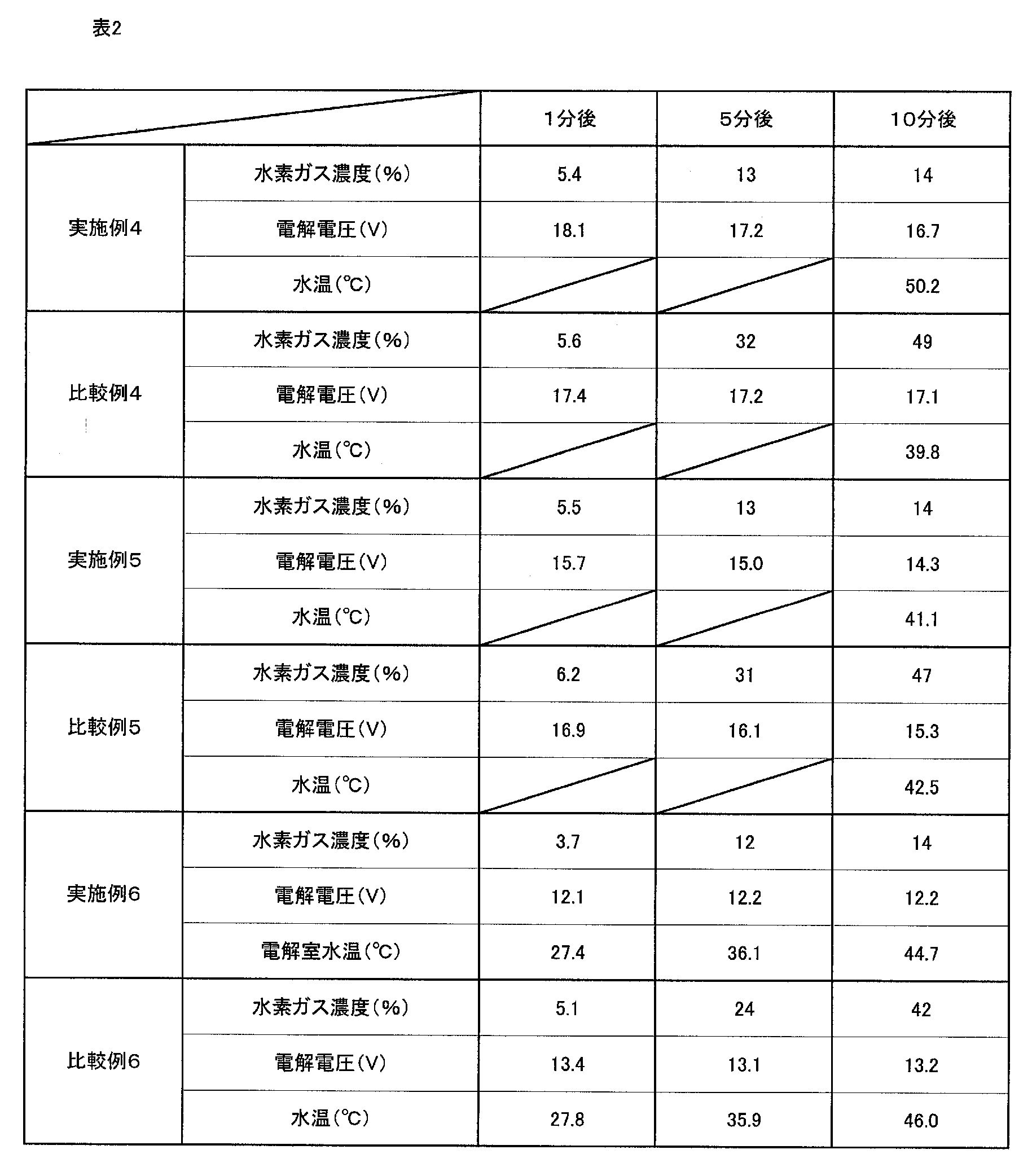
実施例4から6において、通常大気を送風しない場合の、電解開始1分後、5分後、電解終了時(電解開始から10分後)における陰極水面から7cmの地点の水素ガス濃度、電解電圧、及び電解室の水温をそれぞれ測定した。その結果を表2に示す。なお比較例4から6に使用した被電解原水の水温は、それぞれ20.1℃、20.8℃、26.2℃であった。 [Comparative Examples 4 to 6]
In Examples 4 to 6, the hydrogen gas concentration and electrolysis voltage at a point 7 cm from the cathode water surface at the end of electrolysis (after 10 minutes from the start of electrolysis) after 1 minute, 5 minutes and after the start of electrolysis, when normal air is not blown The water temperature in the electrolysis chamber was measured. The results are shown in Table 2. The water temperatures of the electrolyzed raw water used in Comparative Examples 4 to 6 were 20.1 ° C., 20.8 ° C., and 26.2 ° C., respectively.
被電解原水が導入される電解室と、電解室における内と外を区画する陽イオン交換膜(「ナフィオン424」(デュポン社製))と、電解室内外のそれぞれに、陽イオン交換膜を挟んで設けられた一対の白金電極と、を有し、電解室外の電極板が陽イオン交換膜に接触させて設けられており、さらに電解室内の電極板も陽イオン交換膜に接触させて設けられている電解槽の電解室に、水温25.8℃の藤沢市水道水1.4Lを入れるとともに陽イオン交換膜にも水を湿潤させた。 [Example 7]
An electrolytic chamber into which raw water to be electrolyzed is introduced, a cation exchange membrane (“Nafion 424” (manufactured by DuPont)) that divides the inside and outside of the electrolytic chamber, and a cation exchange membrane between the inside and outside of the electrolytic chamber A pair of platinum electrodes provided in the electrode chamber, the electrode plate outside the electrolysis chamber is provided in contact with the cation exchange membrane, and the electrode plate in the electrolysis chamber is provided in contact with the cation exchange membrane. Then, 1.4 L of Fujisawa city tap water having a water temperature of 25.8 ° C. was placed in the electrolytic chamber of the electrolytic cell, and the cation exchange membrane was also wetted with water.
実施例4の電解槽においてさらに電解室外の電極板を囲む側室を設けるとともに、電解室と側室に水温26.3℃の藤沢市水道水を1.4Lずつ入れ、電解室内に設けられた電極板を陰極とし、電解室外に設けられた電極板を陽極として直流電源からの直流電圧を両電極間に印加し、電解電流27Aで電気分解した。 [Example 8]
In the electrolytic cell of Example 4, a side chamber surrounding the electrode plate outside the electrolysis chamber is further provided, and 1.4 L each of Fujisawa city tap water having a water temperature of 26.3 ° C. is placed in the electrolysis chamber and the side chamber, and the electrode plate provided in the electrolysis chamber Was used as a cathode, an electrode plate provided outside the electrolysis chamber was used as an anode, a DC voltage from a DC power source was applied between both electrodes, and electrolysis was performed with an electrolysis current 27A.
被電解原水が導入される電解室と、電解室における内と外を区画する上記の陽イオン交換膜と、電解室内外のそれぞれに、陽イオン交換膜を挟んで設けられた一対の白金電極と、を有し、電解室外の電極板が陽イオン交換膜に接触させて設けられており、さらに電解室内の電極板も陽イオン交換膜に接触させて設けられていることを特徴とする電解槽の電解室に、水温25.8℃の藤沢市水道水1.4Lを入れるとともに、電解室内に設けられた電極板を陽極とし、電解室外に設けられた電極板を陰極として直流電源からの直流電圧を両電極間に印加し、電解電流27Aで電気分解した。 [Example 9]
An electrolysis chamber into which raw water to be electrolyzed is introduced, the above-described cation exchange membrane that partitions the inside and outside of the electrolysis chamber, and a pair of platinum electrodes that are provided outside and inside the electrolysis chamber with a cation exchange membrane interposed therebetween, And an electrode plate outside the electrolysis chamber is provided in contact with the cation exchange membrane, and an electrode plate inside the electrolysis chamber is also provided in contact with the cation exchange membrane. Into the electrolytic chamber, 1.4 L of Fujisawa city tap water having a water temperature of 25.8 ° C. is put, and the electrode plate provided in the electrolytic chamber is used as an anode, and the electrode plate provided outside the electrolytic chamber is used as a cathode. A voltage was applied between both electrodes and electrolysis was performed with an electrolysis current of 27A.
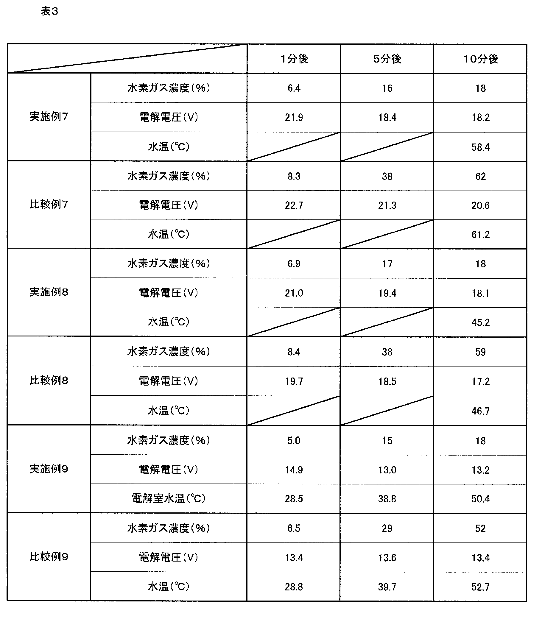
実施例7から9において、通常大気を送風しない場合の、電解開始1分後、5分後、電解終了時(電解開始から10分後)における陰極水面から7cmの地点の水素ガス濃度、電解電圧、及び電解室の水温をそれぞれ測定した。その結果を表3に示す。なお比較例7から9に使用した被電解原水の水温は、それぞれ25.9℃、26.8℃、25.9℃であった。 [Comparative Examples 7 to 9]
In Examples 7 to 9, the hydrogen gas concentration and the electrolysis voltage at a point 7 cm from the cathode water surface at the end of electrolysis (after 10 minutes from the start of electrolysis) after 1 minute, 5 minutes and after the start of electrolysis in the case where normal air is not blown The water temperature in the electrolysis chamber was measured. The results are shown in Table 3. The water temperatures of the electrolyzed raw water used in Comparative Examples 7 to 9 were 25.9 ° C., 26.8 ° C., and 25.9 ° C., respectively.
11…電解室
12…被電解原水
13…隔膜
14,15…電極板
16…側室
17,17a…希釈用ガス導入口
18,18a…混合ガス導出口
2…直流電源
3…希釈用ガス供給器
4…ヘッドスペース部 DESCRIPTION OF
Claims (11)
- 被電解原水が導入される電解室と、前記電解室の内部と外部とを区画する一つ以上の隔膜と、前記電解室の内部及び外部のそれぞれに前記隔膜を挟んで設けられた少なくとも一対の電極板と、を有し、前記電解室の外部の電極板が前記隔膜に接触させて設けられている電解槽と、
前記一対の電極板に直流電圧を印加する直流電源と、
陰極となる電極板から発生する水素ガスを希釈するための希釈用ガス供給器と、を備え、
前記希釈用ガス供給器から供給される希釈用ガスを前記陰極又は陰極水面に送風することにより、電解時の前記陰極又は前記陰極水面から7cm離れた位置の水素ガス濃度を常に18.3vol%未満に維持し、水素ガス濃度が0.1~18.3vol%の、水素ガスと希釈用ガスを含む混合ガスを生体に供給する生体用高濃度水素ガス供給装置。 An electrolysis chamber into which raw water to be electrolyzed is introduced, one or more diaphragms partitioning the inside and the outside of the electrolysis chamber, and at least a pair of the diaphragms interposed between the inside and the outside of the electrolysis chamber An electrode plate, and an electrolytic cell in which an electrode plate outside the electrolysis chamber is provided in contact with the diaphragm;
A DC power supply for applying a DC voltage to the pair of electrode plates;
A gas supply device for dilution for diluting hydrogen gas generated from the electrode plate serving as a cathode,
By blowing the dilution gas supplied from the dilution gas supply device to the cathode or the cathode water surface, the hydrogen gas concentration at a position 7 cm away from the cathode or the cathode water surface during electrolysis is always less than 18.3 vol%. And a high-concentration hydrogen gas supply device for a living body that supplies the living body with a mixed gas containing hydrogen gas and a dilution gas having a hydrogen gas concentration of 0.1 to 18.3 vol%. - 請求項1に記載の生体用高濃度水素ガス供給装置において、
前記希釈用ガス供給器から供給される希釈用ガスを前記陰極又は陰極水面に送風することにより、電解時の前記陰極又は前記陰極水面から7cm離れた位置の水素ガス濃度を常に4vol%未満に維持し、水素ガス濃度が0.1~4vol%の、水素ガスと希釈用ガスを含む混合ガスを生体に供給する生体用高濃度水素ガス供給装置。 The high-concentration hydrogen gas supply device for living body according to claim 1,
By blowing the dilution gas supplied from the dilution gas supply device to the cathode or the cathode water surface, the hydrogen gas concentration at a position 7 cm away from the cathode or the cathode water surface during electrolysis is always maintained below 4 vol%. And a high-concentration hydrogen gas supply device for a living body that supplies a mixed gas containing hydrogen gas and dilution gas having a hydrogen gas concentration of 0.1 to 4 vol% to the living body. - 請求項1に記載の生体用高濃度水素ガス供給装置において、
さらに前記電解室の内部の電極板が前記隔膜に接触させて設けられている生体用高濃度水素ガス供給装置。 The high-concentration hydrogen gas supply device for living body according to claim 1,
Furthermore, a high-concentration hydrogen gas supply device for a living body, in which an electrode plate inside the electrolysis chamber is provided in contact with the diaphragm. - 請求項1に記載の生体用高濃度水素ガス供給装置において、
前記電解室には、前記希釈用ガス供給器からの希釈用ガスを導入する希釈用ガス導入口と、前記混合ガスを導出する混合ガス導出口とが設けられ、
前記電解室の内部に被電解原水が導入されている状態で、前記電解室の内部に設けられた電極板を陰極とし、前記電解室の外部に設けられた電極板を陽極として、前記直流電源からの直流電圧を両電極板に印加する生体用高濃度水素ガス供給装置。 The high-concentration hydrogen gas supply device for living body according to claim 1,
The electrolysis chamber is provided with a dilution gas introduction port for introducing a dilution gas from the dilution gas supply device, and a mixed gas outlet port for deriving the mixed gas,
With the raw water to be electrolyzed introduced into the electrolysis chamber, the electrode plate provided inside the electrolysis chamber is used as a cathode, and the electrode plate provided outside the electrolysis chamber is used as an anode, and the DC power supply A high-concentration hydrogen gas supply device for living organisms that applies a DC voltage from both to the electrode plates. - 請求項1に記載の生体用高濃度水素ガス供給装置において、
前記電解室の外部に、前記一対の電極板の一方の電極板を包含する側室が設けられている生体用高濃度水素ガス供給装置。 The high-concentration hydrogen gas supply device for living body according to claim 1,
A high-concentration hydrogen gas supply device for a living body, wherein a side chamber including one electrode plate of the pair of electrode plates is provided outside the electrolysis chamber. - 請求項5に記載の生体用高濃度水素ガス供給装置において、
前記側室には、前記希釈用ガス供給器からの希釈用ガスを導入する希釈用ガス導入口と、前記混合ガスを導出する混合ガス導出口とが設けられて、
前記電解室の内部に被電解原水が導入されている状態で、前記電解室の内部に設けられた電極板を陽極とし、前記電解室の外部に設けられた電極板を陰極として、前記直流電源からの直流電圧を両電極板に印加する生体用高濃度水素ガス供給装置。 The high-concentration hydrogen gas supply device for living body according to claim 5,
The side chamber is provided with a dilution gas introduction port for introducing a dilution gas from the dilution gas supply device, and a mixed gas outlet port for deriving the mixed gas,
With the raw water to be electrolyzed introduced into the electrolysis chamber, the electrode plate provided inside the electrolysis chamber is used as an anode, the electrode plate provided outside the electrolysis chamber is used as a cathode, and the DC power supply A high-concentration hydrogen gas supply device for living organisms that applies a DC voltage from both to the electrode plates. - 請求項5に記載の生体用高濃度水素ガス供給装置において、
前記電解室の内部および前記側室に被電解原水が導入される生体用高濃度水素ガス供給装置。 The high-concentration hydrogen gas supply device for living body according to claim 5,
A biological high-concentration hydrogen gas supply device in which raw water to be electrolyzed is introduced into the electrolysis chamber and the side chamber. - 請求項1に記載の生体用高濃度水素ガス供給装置において、
前記希釈用ガスが通常大気である生体用高濃度水素ガス供給装置。 The high-concentration hydrogen gas supply device for living body according to claim 1,
A biological high-concentration hydrogen gas supply device in which the gas for dilution is usually the atmosphere. - 請求項1に記載の生体用高濃度水素ガス供給装置において、
前記希釈用ガスが2L/分以上の通気量で送風される生体用高濃度水素ガス供給装置。 The high-concentration hydrogen gas supply device for living body according to claim 1,
A biological high-concentration hydrogen gas supply device in which the dilution gas is blown at an air flow rate of 2 L / min or more. - 請求項1に記載の生体用高濃度水素ガス供給装置において、
前記混合ガスの塩素ガス濃度が1ppm以下である生体用高濃度水素ガス供給装置。 The high-concentration hydrogen gas supply device for living body according to claim 1,
A biological high-concentration hydrogen gas supply device in which the mixed gas has a chlorine gas concentration of 1 ppm or less. - 請求項1に記載の生体用高濃度水素ガス供給装置において、
前記直流電圧を印加するのと同時にまたはこれに先立って、希釈用ガス供給器を作動させる生体用高濃度水素ガス供給装置。 The high-concentration hydrogen gas supply device for living body according to claim 1,
A biological high-concentration hydrogen gas supply device that operates a dilution gas supply device simultaneously with or prior to the application of the DC voltage.
Priority Applications (6)
| Application Number | Priority Date | Filing Date | Title |
|---|---|---|---|
| US14/405,109 US9717877B2 (en) | 2012-06-04 | 2013-05-22 | Apparatus for supplying high-concentration hydrogen gas for living organism |
| KR1020147036753A KR101511008B1 (en) | 2012-06-04 | 2013-05-22 | High-Concentration Hydrogen Gas Supply Device for Living Bodies |
| IN10597DEN2014 IN2014DN10597A (en) | 2012-06-04 | 2013-05-22 | |
| CN201380029653.6A CN104379812B (en) | 2012-06-04 | 2013-05-22 | Organism high concentration of hydrogen air feed system |
| EP13800208.4A EP2857555B1 (en) | 2012-06-04 | 2013-05-22 | High-concentration hydrogen gas supply device for living bodies |
| HK15104954.9A HK1204346A1 (en) | 2012-06-04 | 2015-05-26 | High-concentration hydrogen gas supply device for living bodies |
Applications Claiming Priority (4)
| Application Number | Priority Date | Filing Date | Title |
|---|---|---|---|
| JP2012-127296 | 2012-06-04 | ||
| JP2012127296A JP5091364B1 (en) | 2012-06-04 | 2012-06-04 | Biological hydrogen gas supply device |
| JP2012-176861 | 2012-08-09 | ||
| JP2012176861A JP5100911B1 (en) | 2012-08-09 | 2012-08-09 | High concentration hydrogen gas supply device for living body |
Publications (1)
| Publication Number | Publication Date |
|---|---|
| WO2013183448A1 true WO2013183448A1 (en) | 2013-12-12 |
Family
ID=49711846
Family Applications (1)
| Application Number | Title | Priority Date | Filing Date |
|---|---|---|---|
| PCT/JP2013/064175 WO2013183448A1 (en) | 2012-06-04 | 2013-05-22 | High-concentration hydrogen gas supply device for living bodies |
Country Status (8)
| Country | Link |
|---|---|
| US (1) | US9717877B2 (en) |
| EP (1) | EP2857555B1 (en) |
| KR (1) | KR101511008B1 (en) |
| CN (1) | CN104379812B (en) |
| HK (1) | HK1204346A1 (en) |
| IN (1) | IN2014DN10597A (en) |
| TW (1) | TWI526228B (en) |
| WO (1) | WO2013183448A1 (en) |
Cited By (5)
| Publication number | Priority date | Publication date | Assignee | Title |
|---|---|---|---|---|
| JP2015183004A (en) * | 2014-03-25 | 2015-10-22 | リン, シン−ユンLin, Hsin−Yung | Inhalation-type pharmaceutical composition for treatment of parkinson's disease and preparation method thereof |
| JP2015183005A (en) * | 2014-03-25 | 2015-10-22 | リン, シン−ユンLin, Hsin−Yung | Inhalation-type pharmaceutical composition for treatment of alzheimer's disease and preparation method thereof |
| JP2015183006A (en) * | 2014-03-25 | 2015-10-22 | リン, シン−ユンLin, Hsin−Yung | Inhalation pharmaceutical composition for treating heart disease and method of preparation thereof |
| WO2017149684A1 (en) * | 2016-03-01 | 2017-09-08 | 株式会社グレイトチレン | Wet high-concentration hydrogen-mixed-gas respiration system |
| US10435798B2 (en) * | 2015-08-11 | 2019-10-08 | Miz Company Limited | Hydrogen gas generator |
Families Citing this family (14)
| Publication number | Priority date | Publication date | Assignee | Title |
|---|---|---|---|---|
| JP5502973B1 (en) * | 2012-11-30 | 2014-05-28 | ミズ株式会社 | High concentration hydrogen gas supply device for living body |
| CN109395224A (en) * | 2013-06-19 | 2019-03-01 | 上海潓美医疗科技有限公司 | Health care gas generator |
| JP5612743B1 (en) * | 2013-09-01 | 2014-10-22 | 河村 隆夫 | High concentration hydrogen mixed gas breathing system |
| CN103785091B (en) * | 2014-01-07 | 2018-05-04 | 林信涌 | Health care gas generating system |
| CN103938219B (en) * | 2014-04-12 | 2017-01-04 | 大连双迪创新科技研究院有限公司 | Excess microbubble hydrogen device for making |
| US20160263341A1 (en) * | 2015-03-09 | 2016-09-15 | Hsin-Yung Lin | Gas generator |
| CN106906483B (en) * | 2015-12-22 | 2019-03-22 | 林信涌 | Gas generator |
| TWI606146B (en) | 2015-12-22 | 2017-11-21 | 林信湧 | A gas generator |
| CN106344982B (en) * | 2016-09-30 | 2020-12-08 | 福州品行科技发展有限公司 | Cupping jar and using method thereof |
| WO2018151107A1 (en) * | 2017-02-14 | 2018-08-23 | 株式会社アクアバンク | Bioactivation method for enhancing neural activity and blood circulation activity of living body |
| KR20190127925A (en) * | 2017-11-08 | 2019-11-13 | 아쿠아 뱅크 주식회사 | Smoking combined hydrogen suction device |
| WO2019093281A1 (en) * | 2017-11-09 | 2019-05-16 | 株式会社アクアバンク | Health management system and program for same |
| JP6786754B2 (en) * | 2018-01-09 | 2020-11-18 | 株式会社アクアバンク | Portable gas suction device |
| US20220218970A1 (en) * | 2019-05-10 | 2022-07-14 | To2M Corporation | Method for promoting hair growth and improving white hair condition, and device and apparatus thereof |
Citations (4)
| Publication number | Priority date | Publication date | Assignee | Title |
|---|---|---|---|---|
| JPH09186133A (en) * | 1996-01-08 | 1997-07-15 | Shinko Pantec Co Ltd | Silicon wafer surface processing method |
| JP3349710B2 (en) | 1997-08-27 | 2002-11-25 | ミズ株式会社 | Electrolyzer and electrolyzed water generator |
| JP2009005881A (en) | 2007-06-28 | 2009-01-15 | Shinwa Kogyo Kk | Inhalation device of hydrogen gas into body |
| JP2009228044A (en) * | 2008-03-21 | 2009-10-08 | Kurita Water Ind Ltd | Method of treating hydrogen-containing gas |
Family Cites Families (6)
| Publication number | Priority date | Publication date | Assignee | Title |
|---|---|---|---|---|
| JP2005087257A (en) | 2003-09-12 | 2005-04-07 | Shinwa Kogyo Kk | Method of inhalation of hydrogen gas into body and its device |
| JP2005097667A (en) * | 2003-09-24 | 2005-04-14 | Air Liquide Japan Ltd | Gaseous fluorine generator |
| JP2006000792A (en) * | 2004-06-18 | 2006-01-05 | Ebara Corp | Apparatus and method for electrodeposition treatment |
| JP4967001B2 (en) * | 2009-03-13 | 2012-07-04 | ミズ株式会社 | Method for producing hydrogen-containing biological fluid and apparatus therefor |
| IT1398498B1 (en) * | 2009-07-10 | 2013-03-01 | Acta Spa | DEVICE FOR THE PRODUCTION ON DEMAND OF HYDROGEN BY MEANS OF ELECTROLYSIS OF WATER SOLUTIONS. |
| JP5502973B1 (en) * | 2012-11-30 | 2014-05-28 | ミズ株式会社 | High concentration hydrogen gas supply device for living body |
-
2013
- 2013-05-22 EP EP13800208.4A patent/EP2857555B1/en active Active
- 2013-05-22 CN CN201380029653.6A patent/CN104379812B/en active Active
- 2013-05-22 KR KR1020147036753A patent/KR101511008B1/en active IP Right Grant
- 2013-05-22 US US14/405,109 patent/US9717877B2/en active Active
- 2013-05-22 WO PCT/JP2013/064175 patent/WO2013183448A1/en active Application Filing
- 2013-05-22 IN IN10597DEN2014 patent/IN2014DN10597A/en unknown
- 2013-05-29 TW TW102118905A patent/TWI526228B/en active
-
2015
- 2015-05-26 HK HK15104954.9A patent/HK1204346A1/en unknown
Patent Citations (4)
| Publication number | Priority date | Publication date | Assignee | Title |
|---|---|---|---|---|
| JPH09186133A (en) * | 1996-01-08 | 1997-07-15 | Shinko Pantec Co Ltd | Silicon wafer surface processing method |
| JP3349710B2 (en) | 1997-08-27 | 2002-11-25 | ミズ株式会社 | Electrolyzer and electrolyzed water generator |
| JP2009005881A (en) | 2007-06-28 | 2009-01-15 | Shinwa Kogyo Kk | Inhalation device of hydrogen gas into body |
| JP2009228044A (en) * | 2008-03-21 | 2009-10-08 | Kurita Water Ind Ltd | Method of treating hydrogen-containing gas |
Non-Patent Citations (1)
| Title |
|---|
| See also references of EP2857555A4 * |
Cited By (5)
| Publication number | Priority date | Publication date | Assignee | Title |
|---|---|---|---|---|
| JP2015183004A (en) * | 2014-03-25 | 2015-10-22 | リン, シン−ユンLin, Hsin−Yung | Inhalation-type pharmaceutical composition for treatment of parkinson's disease and preparation method thereof |
| JP2015183005A (en) * | 2014-03-25 | 2015-10-22 | リン, シン−ユンLin, Hsin−Yung | Inhalation-type pharmaceutical composition for treatment of alzheimer's disease and preparation method thereof |
| JP2015183006A (en) * | 2014-03-25 | 2015-10-22 | リン, シン−ユンLin, Hsin−Yung | Inhalation pharmaceutical composition for treating heart disease and method of preparation thereof |
| US10435798B2 (en) * | 2015-08-11 | 2019-10-08 | Miz Company Limited | Hydrogen gas generator |
| WO2017149684A1 (en) * | 2016-03-01 | 2017-09-08 | 株式会社グレイトチレン | Wet high-concentration hydrogen-mixed-gas respiration system |
Also Published As
| Publication number | Publication date |
|---|---|
| KR20150009608A (en) | 2015-01-26 |
| IN2014DN10597A (en) | 2015-09-11 |
| CN104379812B (en) | 2016-12-14 |
| EP2857555A1 (en) | 2015-04-08 |
| TWI526228B (en) | 2016-03-21 |
| KR101511008B1 (en) | 2015-04-10 |
| CN104379812A (en) | 2015-02-25 |
| US20150144132A1 (en) | 2015-05-28 |
| EP2857555B1 (en) | 2016-09-07 |
| EP2857555A4 (en) | 2015-05-06 |
| US9717877B2 (en) | 2017-08-01 |
| HK1204346A1 (en) | 2015-11-13 |
| TW201410281A (en) | 2014-03-16 |
Similar Documents
| Publication | Publication Date | Title |
|---|---|---|
| WO2013183448A1 (en) | High-concentration hydrogen gas supply device for living bodies | |
| JP5091364B1 (en) | Biological hydrogen gas supply device | |
| JP5502973B1 (en) | High concentration hydrogen gas supply device for living body | |
| TWI592518B (en) | Hydrogen generating device | |
| JP5900688B1 (en) | Hydrogen gas generator | |
| CN101713080B (en) | Electrolytic device for generation of ph-controlled hypohalous acid aqueous solutions for disinfectant applications | |
| US10364503B2 (en) | Medical gas-liquid supply system | |
| JP5100911B1 (en) | High concentration hydrogen gas supply device for living body | |
| JP6667873B2 (en) | Biological hydrogen gas supply device | |
| TWM536542U (en) | Healthy gas generating system | |
| KR101600963B1 (en) | Device for generating high concentration of oxygen gas | |
| JP2017179556A (en) | Hydrogen gas generator | |
| JP2021193212A (en) | Hydrogen gas generation apparatus | |
| WO2022201370A1 (en) | Gas supply device and gas supply method | |
| JP2015196872A (en) | Apparatus and method for supply of radical oxygen water | |
| CN111219782A (en) | Oxygen generator and oxygen generating air conditioner | |
| TWM491675U (en) | Hydrogen generation machine capable of outputting pure hydrogen gas | |
| CN112553644A (en) | Hydrogen machine | |
| TW200831711A (en) | Portable oxygen maintenance and regulation concentrator apparatus | |
| TH11662EX (en) | Oxygen generator with easy dispensing system Economical and safe |
Legal Events
| Date | Code | Title | Description |
|---|---|---|---|
| 121 | Ep: the epo has been informed by wipo that ep was designated in this application |
Ref document number: 13800208 Country of ref document: EP Kind code of ref document: A1 |
|
| REEP | Request for entry into the european phase |
Ref document number: 2013800208 Country of ref document: EP |
|
| WWE | Wipo information: entry into national phase |
Ref document number: 2013800208 Country of ref document: EP |
|
| WWE | Wipo information: entry into national phase |
Ref document number: 14405109 Country of ref document: US |
|
| NENP | Non-entry into the national phase |
Ref country code: DE |
|
| ENP | Entry into the national phase |
Ref document number: 20147036753 Country of ref document: KR Kind code of ref document: A |