WO2013176213A1 - Air-blowing device, and charged particle delivery device - Google Patents
Air-blowing device, and charged particle delivery device Download PDFInfo
- Publication number
- WO2013176213A1 WO2013176213A1 PCT/JP2013/064334 JP2013064334W WO2013176213A1 WO 2013176213 A1 WO2013176213 A1 WO 2013176213A1 JP 2013064334 W JP2013064334 W JP 2013064334W WO 2013176213 A1 WO2013176213 A1 WO 2013176213A1
- Authority
- WO
- WIPO (PCT)
- Prior art keywords
- charged particle
- air
- blower
- housing
- generating element
- Prior art date
Links
Images


Classifications
-
- F—MECHANICAL ENGINEERING; LIGHTING; HEATING; WEAPONS; BLASTING
- F04—POSITIVE - DISPLACEMENT MACHINES FOR LIQUIDS; PUMPS FOR LIQUIDS OR ELASTIC FLUIDS
- F04D—NON-POSITIVE-DISPLACEMENT PUMPS
- F04D25/00—Pumping installations or systems
- F04D25/02—Units comprising pumps and their driving means
- F04D25/08—Units comprising pumps and their driving means the working fluid being air, e.g. for ventilation
- F04D25/12—Units comprising pumps and their driving means the working fluid being air, e.g. for ventilation the unit being adapted for mounting in apertures
- F04D25/14—Units comprising pumps and their driving means the working fluid being air, e.g. for ventilation the unit being adapted for mounting in apertures and having shutters, e.g. automatically closed when not in use
-
- F—MECHANICAL ENGINEERING; LIGHTING; HEATING; WEAPONS; BLASTING
- F24—HEATING; RANGES; VENTILATING
- F24F—AIR-CONDITIONING; AIR-HUMIDIFICATION; VENTILATION; USE OF AIR CURRENTS FOR SCREENING
- F24F8/00—Treatment, e.g. purification, of air supplied to human living or working spaces otherwise than by heating, cooling, humidifying or drying
- F24F8/10—Treatment, e.g. purification, of air supplied to human living or working spaces otherwise than by heating, cooling, humidifying or drying by separation, e.g. by filtering
-
- F—MECHANICAL ENGINEERING; LIGHTING; HEATING; WEAPONS; BLASTING
- F24—HEATING; RANGES; VENTILATING
- F24F—AIR-CONDITIONING; AIR-HUMIDIFICATION; VENTILATION; USE OF AIR CURRENTS FOR SCREENING
- F24F13/00—Details common to, or for air-conditioning, air-humidification, ventilation or use of air currents for screening
- F24F13/02—Ducting arrangements
- F24F13/06—Outlets for directing or distributing air into rooms or spaces, e.g. ceiling air diffuser
- F24F13/062—Outlets for directing or distributing air into rooms or spaces, e.g. ceiling air diffuser having one or more bowls or cones diverging in the flow direction
-
- F—MECHANICAL ENGINEERING; LIGHTING; HEATING; WEAPONS; BLASTING
- F24—HEATING; RANGES; VENTILATING
- F24F—AIR-CONDITIONING; AIR-HUMIDIFICATION; VENTILATION; USE OF AIR CURRENTS FOR SCREENING
- F24F13/00—Details common to, or for air-conditioning, air-humidification, ventilation or use of air currents for screening
- F24F13/08—Air-flow control members, e.g. louvres, grilles, flaps or guide plates
- F24F13/10—Air-flow control members, e.g. louvres, grilles, flaps or guide plates movable, e.g. dampers
-
- F—MECHANICAL ENGINEERING; LIGHTING; HEATING; WEAPONS; BLASTING
- F24—HEATING; RANGES; VENTILATING
- F24F—AIR-CONDITIONING; AIR-HUMIDIFICATION; VENTILATION; USE OF AIR CURRENTS FOR SCREENING
- F24F13/00—Details common to, or for air-conditioning, air-humidification, ventilation or use of air currents for screening
- F24F13/20—Casings or covers
- F24F2013/205—Mounting a ventilator fan therein
-
- H—ELECTRICITY
- H01—ELECTRIC ELEMENTS
- H01T—SPARK GAPS; OVERVOLTAGE ARRESTERS USING SPARK GAPS; SPARKING PLUGS; CORONA DEVICES; GENERATING IONS TO BE INTRODUCED INTO NON-ENCLOSED GASES
- H01T19/00—Devices providing for corona discharge
- H01T19/04—Devices providing for corona discharge having pointed electrodes
-
- H—ELECTRICITY
- H01—ELECTRIC ELEMENTS
- H01T—SPARK GAPS; OVERVOLTAGE ARRESTERS USING SPARK GAPS; SPARKING PLUGS; CORONA DEVICES; GENERATING IONS TO BE INTRODUCED INTO NON-ENCLOSED GASES
- H01T23/00—Apparatus for generating ions to be introduced into non-enclosed gases, e.g. into the atmosphere
Definitions
- the present invention relates to a desktop blower and a charged particle delivery device.
- Household electrical equipment includes various blower devices such as fans, ventilation fans, air purifiers, and air conditioners. Some electric fans and air purifiers are small and are intended to be used on a table.
- Patent Document 1 describes an air purifier that is an example of a blower.
- This air purifier has an operation panel on the top front of the casing, on which a number of operation buttons including a power on / off button are arranged.
- a conventional tabletop blower includes a housing in which a blower fan and a motor that rotates the blower fan are arranged.
- a suction port and a blower outlet are formed in the housing.
- Power supply may be performed using a power cord.
- one end of the power cord is connected to a terminal portion provided in the blower, and the other end is connected to an external power source such as a commercial power source.
- an external power source such as a commercial power source.
- a magnet method or an insertion method can be considered.
- a magnet plug provided at one end of the power cord is detachably connected to a plug receiver provided in the blower (see Patent Document 2).
- an insertion plug provided at one end of the power cord is detachably connected to a plug receiver provided in the blower.
- charged particle delivery devices which are a type of blower, are often placed indoors. Examples of such charged particle delivery devices can be found in US Pat.
- the air blower described in Patent Document 3 includes a casing having an inlet and an outlet, an air blowing fan disposed in the casing and covered with a casing having an inlet and an outlet, and an exhaust and an outlet. And an ion generating element (charged particle generating element) for generating ions (charged particles) in the duct.
- the ion generating element has a discharge electrode, and ions are generated by applying a voltage to the discharge electrode.
- a filter facing the suction port may be arranged for the purpose of removing dust contained in the air.
- a filter it is difficult to remove all dust contained in the air, and it has not been possible to prevent dust from accumulating in the duct. Therefore, it is desirable to periodically clean the inside of the duct, particularly the inside of the duct near the ion generating element.
- the charged particle delivery device described in Patent Document 3 delivers ions as charged particles.
- the main body case has a built-in fan, and an ion generator, which is a charged particle generator, and an ion And a detector.
- a small air blower used on a table has a limited space for arranging operation buttons.
- only the ones that start and end are required to have a clean design with a small number of operation buttons.
- the housing case in which the ion generating element is housed can be attached and detached by removing the rear wall from the housing.
- the duct is not arranged near the back wall, it is difficult to clean the inside of the duct near the ion generator.
- a charged particle delivery device installed indoors as a single device generally has an air outlet formed on the upper surface in order to dissipate charged particles throughout the room.
- the air flow path extends in the vertical direction in order to guide the airflow generated by the fan to the outlet and to blow it upward.
- a constricted portion is formed in the middle of the air passage extending in the vertical direction, and the charged particle generator is disposed there. Therefore, the length of the air passage in the vertical direction is long. Therefore, the charged particle delivery device as a whole has a high height.
- the present invention has been made in view of the above points, and a first object is to operate a power switch without being aware of the presence of the power switch in a small blower suitable for use on a tabletop. Is to provide a structure.
- the second object is to provide a blower that can easily prevent poor contact during use.
- a third object is to provide an air blower that can be easily cleaned in a duct near a charged particle generating element.
- a fourth object is to provide a charged particle delivery device that does not take a height and can be used on a desk, for example.
- the blower according to the present invention includes a housing in which a suction port and an air outlet are formed, and an air flow that is sucked into the housing from the suction port and blown out of the housing from the air outlet.
- a blower fan disposed at the air outlet, a wind direction plate disposed at the air outlet and displaceable between a position where the air outlet is opened and a position where the air outlet is closed, and the air direction plate comes to a position where the air outlet is opened.
- a power switch of the blower fan that is turned on when the airflow direction plate comes to a position for closing the air outlet.
- the air outlet is opened when the wind direction plate is displaced so as to jump out of the housing, and the air outlet is closed when the air direction plate is displaced so as to be pushed into the housing. Is preferred.
- the wind direction plate is attached to a slide body that is slidable with respect to the housing, and the power switch is turned on / off in conjunction with the slide of the slide body.
- locking means are provided.
- the urging force of the urging means is set so that the power switch is turned off when the air blower is installed with the air outlet facing down.
- the air outlet is formed on an upper surface of the casing.
- the air outlet has a circular shape and the wind direction plate has an umbrella shape.
- the blower according to the present invention has a blower fan disposed in a housing having an inlet and an outlet, and the blower is installed on an installation surface on which an installation portion provided on one surface of the housing is in contact.
- a power cord that has a plug and supplies power; and a terminal portion that is provided on one surface of the housing and is detachably inserted and faces the installation surface, and the installation portion on the installation surface And when the said plug contact
- the plug and the terminal part are electrically connected.
- the state where the installation part and the plug are not in contact with the installation surface is a state where the blower is installed on the installation surface in an unstable state. That is, since the plug and the terminal portion are electrically connected when the blower is stably installed on the installation surface, it is possible to easily grasp the conductive state between the plug and the terminal portion. Also, even if the plug is not fully inserted into the terminal part and the installation part and the plug are not in contact with the installation surface, the installation part and plug are applied to the installation surface by applying force to the housing. By making contact, the plug and the terminal portion are electrically connected. Therefore, the plug and the terminal portion can be easily conducted without directly touching the plug.
- a plate portion detachably attached to the housing is provided, the plug is inserted into the terminal portion through an insertion hole opened in the plate portion, and the plate portion is attached to and detached from the plug. It is desirable to form it detachably.
- the plug is connected to the terminal portion through the insertion hole that opens in the plate portion that is detachable from the housing. Further, since the plate portion is formed so as to be detachable by detaching the plug, in order to remove the plate portion from the housing, it is necessary to remove the plug from the terminal portion. That is, when the plate portion is removed, power is not supplied to the blower, and therefore, when the user removes the plate portion and cleans the inside of the housing, the user does not get an electric shock by touching various electronic components.
- the blower configured as described above includes a charged particle generating element that generates charged particles, wherein the plate portion is detachable by detaching the plug, and the charged particle generating element is attached and detached when the plate portion is removed. It is desirable to be able to do it.
- the charged particle generating element can be detached from the bottom surface of the housing when the plate portion is removed, the charged particle generating element can be easily replaced or cleaned.
- the plate portion is formed so as to be detachable by detaching the plug, and the filter is detachable when the plate portion is removed.
- the filter since the filter can be detached from the bottom surface of the housing when the plate portion is removed, the filter can be easily replaced or cleaned.
- the blower according to the present invention includes a housing having an intake port and an air outlet, a blower fan disposed in the housing and covered with a casing having an intake port and an exhaust port, and the exhaust port and the air outlet.
- a blower comprising: a duct communicating with a charged particle generating element that generates charged particles in the duct; and a holding member that holds the charged particle generating element, wherein the holding member is adjacent to the exhaust port. And forming a part of the duct and being detachably arranged integrally with the charged particle generating element with respect to the casing.
- the holding member has a function of holding the charged particle generating element and also functions as a part of the duct.
- the holding member constitutes a duct near the charged particle generating element.
- the holding member is detachably disposed integrally with the charged particle generating element with respect to the housing. That is, since the duct in the vicinity of the charged particle generating element is detachable, the inside of the duct in the vicinity of the charged particle generating element can be easily cleaned. In addition, the charged particle generating element can be easily replaced and cleaned.
- a bottom plate of the housing is detachably provided, and the holding member can be attached and detached by removing the bottom plate.
- the holding member and the charged particle generating element can be detached from the bottom side.
- the direction of the air flow blown out from the exhaust port is converted upward by the bent portion, flows through the duct, and is blown out from the blow-out port. Therefore, the air blowing device can be easily cleaned and the blower device can blow out charged particles from the upper surface side of the housing.
- connection terminal is provided on the upper surface of the charged particle generating element.
- connection terminal is provided on the upper surface of the charged particle generating element held by the holding member that can be detached from the bottom surface side of the housing. Therefore, the weight of the charged particle generating element and the holding member is not applied to the connection terminal. As a result, failure such as damage or deformation of the connection terminal can be prevented.
- the charged particle delivery device includes a housing, a suction port formed in the housing, a blowout port formed on an upper surface of the housing, and is sucked into the housing from the suction port, A blower fan disposed in the housing that forms an airflow blown out of the housing from an air outlet, and a charged particle generating element that discharges charged particles into the airflow from the blower fan, In the air passage leading to the outlet, there is formed a region in which the airflow blown from the blower fan is directed toward the air outlet and the dynamic pressure of the airflow is static, and the charged particles are generated in the region or behind the region. An element is arranged.
- the charged particle generating element is disposed in the region or immediately thereafter.
- the region is preferably a bent portion formed in the air blowing path.
- the outer peripheral side of the bent portion is a curved surface that gradually transitions from the blowing direction of the blower fan to the outlet, and the charged particles are disposed on the outer peripheral side of the bent portion.
- a generator element is preferably arranged.
- the charged particle generating element is disposed at a connection portion between the bent portion and a duct that communicates the bent portion with the air outlet.
- the charged particle generating element includes a positively charged particle generating unit and a negatively charged particle generating unit, and the positively charged particle generating unit and the negatively charged particle generating unit have a predetermined distance in the horizontal direction. It is preferable that they are spaced apart.
- an airflow branching portion that distributes the airflow from the blower fan to the positively charged particle generating portion and the negatively charged particle generating portion is formed in the bent portion.
- the positively charged particle generating unit and the negatively charged particle generating unit are disposed outside the air flow blowing width of the blower fan.
- the positively charged particle generating unit and the negatively charged particle generating unit are formed from needle-like discharge electrodes protruding from a surface facing the blower fan in the casing of the charged particle generating element.
- an electrode protection plate for preventing the discharge electrode from coming into contact with an external object is attached to the casing of the charged particle generating element.
- the charged particle delivery device configured as described above, it is preferable that at least a part of the air passing through the region flows between a case of the charged particle generating element and the electrode protection plate.
- a through hole is formed in the electrode protection plate at a location corresponding to the front surface of the discharge electrode.
- a wind direction plate is arranged at the air outlet on one side of the housing, and the power switch of the blower fan is switched on or off according to the movement of the wind direction plate opening or closing the air outlet. Therefore, it is not necessary to provide an operation button or an operation lever of the power switch on the outer surface of the housing, and the design of the blower can be made clean. Also, if you look at the position of the wind direction plate, you can know at a glance the switching state of the power switch even from a distance.
- the plug and the terminal are electrically connected when the installation part and the plug are in contact with the installation surface.
- the state where the installation part and the plug are not in contact with the installation surface is a state where the blower is installed on the installation surface in an unstable state. That is, since the plug and the terminal portion are electrically connected when the blower is stably installed on the installation surface, it is possible to easily grasp the conductive state between the plug and the terminal portion. Also, even if the plug is not fully inserted into the terminal part and the installation part and the plug are not in contact with the installation surface, the installation part and plug are applied to the installation surface by applying force to the housing. By making contact, the plug and the terminal portion are electrically connected. Therefore, the plug and the terminal portion can be easily conducted without directly touching the plug.
- the holding member has a function of holding the charged particle generating element and also has a function as a part of the duct.
- the holding member constitutes a duct near the charged particle generating element.
- the holding member is detachably disposed integrally with the charged particle generating element with respect to the housing. That is, since the duct in the vicinity of the charged particle generating element is detachable, the inside of the duct in the vicinity of the charged particle generating element can be easily cleaned. In addition, the charged particle generating element can be easily replaced and cleaned.
- the charged particle generating element is disposed in the region where the air flow blown from the blower fan is directed toward the outlet and the dynamic pressure of the air flow is made static or behind the region. Therefore, it is not necessary to make the ventilation path long in the vertical direction for the arrangement of the charged particle generating elements, and the height of the charged particle delivery device can be suppressed. In addition, since the charged particles are discharged into the airflow that has been decelerated by the dynamic pressure being made static in the region, the charged particles can be reliably carried on the airflow.
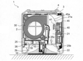
- FIG. 3 is a vertical sectional view in which the blower of FIG. 1 is cut in a direction perpendicular to FIG. 2.
- FIG. 4 is a vertical cross-sectional view in which the blower of FIG. 1 is cross-sectioned with the viewpoint perpendicular to FIG. 2 and opposite to FIG. 3.
- FIG. 6 is a vertical sectional view of the blower of FIG. 5 taken along a direction perpendicular to FIG.
- FIG. 7 is a vertical sectional view similar to FIG. 6, showing a state where the bottom plate of the housing is removed. It is a perspective view of an ion generating element. It is a vertical sectional view showing the state where the air blower according to the embodiment of the present invention falls and is inverted. It is a schematic diagram which shows schematic structure of a charged particle generation part.
- the blower 1 includes a cubic synthetic resin casing 2.
- the right hand side of the user facing the front of the housing 2 is defined as the right side surface of the housing 2, and the left hand side is defined as the left side surface of the housing 2.
- FIG. 9 is a right side view of the blower 1.
- the casing 2 has a cubic shape as described above, and includes six side surfaces (this “side surface” includes the top surface and the bottom surface).
- a suction port is formed on one of the six side surfaces, and a blow-out port is formed on one side surface other than the side surface where the suction port is formed.
- a suction port 2 a (see FIG. 3) is formed on the left side surface of the housing 2, and an air outlet 2 b is formed on the upper surface of the housing 2.
- the suction port 2a is composed of a set of a plurality of through holes.
- the blower outlet 2b has a circular front shape (here, a shape when viewed from above). Moreover, the blower outlet 2b becomes a shape which squeezes down in the shape of a mortar.
- the formation of the air outlet 2b is limited to only one side of the housing 2, but there is no such limitation with respect to the air inlet 2a. It is good also as forming the suction inlet 2a in the some side surface of the housing
- the casing 2 is molded as a single part on the side and top surfaces of the four circumferences, and only the bottom surface is constituted by a separate bottom plate 3.
- the bottom plate 3 is detachable, and rubber legs 4 for stably supporting the housing 2 on the table are provided at the four corners.
- a through hole 3a is formed in the bottom plate 3, and a terminal 35 is disposed in the back of the through hole 3a.
- the power cord 5 may be connected to a household 100V power source or may be connected to a USB terminal of a personal computer or the like.
- two operation buttons are arranged on the right side surface of the housing 2 so as to be lined up and down.
- the upper one is an air volume switching button 50 for switching the air volume of a blower fan to be described later. Each time the air volume switching button 50 is pressed, the air volume is switched from weak to medium to strong.
- An air volume indicator 51 is arranged on the air volume switching button 50.
- the air volume indicator 51 indicates the air volume by the number of vertically long LED lamps. A display with only one LED lamp indicates “low”, and a display with two LED lamps indicates “medium”. A display in which three LED lamps are arranged represents the air volume “strong”.
- the operation button below the air volume switching button 50 is a reset button 52.
- the reset button 52 is pressed after cleaning (cleaning) of a filter and an ion generating element, which will be described later, and indicates the accumulated time from the previous cleaning stored in the control unit (not shown) of the blower 1. It works to reset to zero.
- an indicator 53 for notifying that the filter maintenance time has come is arranged.
- the indicators 53 and 54 are both constituted by LED lamps.
- a hooking hole 2 c having a so-called Dharma hole shape is formed on the back surface of the housing 2. If the retaining hole 2c is hooked on a hook (not shown) protruding from the wall surface of the room, the blower device 1 can be held and used in a wall-hanging state.
- a blower fan 30 is disposed inside the housing 2.
- the blower fan 30 includes a casing 30a, a sirocco fan 30e disposed therein, and a motor 30f that rotates the sirocco fan 30e about a horizontal axis.
- the sirocco fan 30e is of a double-sided suction type, and the casing 30a is formed with an intake port 30b facing one suction surface of the sirocco fan 30e and an intake port 30c facing the other suction surface of the sirocco fan 30e. Yes.
- the intake port 30b is on the side facing the intake port 2a, and the intake port 30c is on the opposite side.
- the suction duct 20 and the duct member 32 are arranged so as to sandwich the blower fan 30 from the left and right.
- the suction duct 20 and the duct member 32 are connected to each other in such a manner that a hook 32e formed at the lower end of the duct member 32 is engaged with a hook receiver 20a formed at the lower end of the suction duct 20.
- the upper ends of the suction duct 20 and the duct member 32 are engaged with the hook and the hook receiver in the same manner as the lower end, and then the connecting member 36 is placed on the upper end of the suction duct 20 and the duct member 32 through the connecting member 36.
- the screw 37 is connected by screwing.
- the blower fan 30 is fixed to the duct member 32 with screws not shown.
- the suction duct 20 extends so as to connect the air inlet 30b of the blower fan 30 and the air inlet 2a of the housing 2.
- a filter 23 detachable from the bottom surface of the housing 2 is disposed between the inlet of the suction duct 20 and the suction port 2a.
- the duct member 32 has a vertical wall portion 32a facing the intake port 30c of the blower fan 30, and an opening portion 32b is formed there.
- a chamfered portion 32c formed at a corner at the lower back of the duct member 32 also serves as an air passage.
- a circuit board 34 on which electronic components such as terminals 35 are mounted is arranged inside the duct member 32 with its plane being vertical, and the circuit board 34 is located in the airflow toward the opening 32b. Electronic components that generate heat can be cooled. If the opening 32b is arranged at a position closer to the upper side of the duct member 32, the air flowing into the duct member 32 from the lower side moves a long distance along the circuit board 34, and the cooling effect is improved.
- the exhaust port 30d (refer FIG. 2) opened toward the front of the housing
- the air discharged from between the fan blades of the sirocco fan 30e swirls clockwise in FIG. 2 in the casing 30a, and is blown out substantially horizontally from the exhaust port 30d.
- the air flow blowing direction from the exhaust port 30d may be a diagonally upward direction with a slight elevation angle, or a diagonally downward direction with a slight depression angle.
- the air blown out from the exhaust port 30d is blown out from the blowout port 2b via a blower passage formed inside the housing 2.
- the blowout duct 21 constitutes the air passage.
- the blowout duct 21 receives the air blown from the exhaust port 30d from the inlet at the lower end, changes the direction of the air flow from the substantially horizontal direction to the vertical direction at the bent portion following the inlet, and blows the air upward from the outlet at the upper end.
- the straight line portion that follows the bent portion in the blowout duct 21 does not necessarily extend in the vertical direction. It may be extended obliquely with a slight angle (for example, an angle within 10 °).
- the bent part of the blowout duct 21 is a static pressure conversion region 21a in which the dynamic pressure of the airflow blown from the exhaust port 30d is converted into a static pressure.
- the ion generating element 40 is disposed immediately after the static pressure conversion region 21a.
- the ion generating element 40 is for discharging ions into the airflow blown out of the housing 2 from the blower outlet 2b.
- the ion generating element 40 is held by a holding member 45 that constitutes a part of the blowing duct 21.
- the holding member 45 is formed with a bent portion 45a on the outer peripheral side of the bent portion of the blowout duct 21.
- the bent portion 45a is a curved surface that gently transitions from the blowing direction of the blower fan 30 to the direction of the blowout port 2b.
- blowing airflow hits from the front, and dynamic pressure is converted into a static pressure.
- the blown airflow is smoothly redirected by the curved surface and guided upward. As a result, both airflows merge and are supplied to the ion generating element 40 while maintaining the airflow velocity while spreading in the lateral width direction of the blowout duct 21.
- the bent portion 45a is a curved surface that gently changes from the blowing direction of the blower fan 30 to the outlet 2b, but the bent portion 45a is formed to be bent substantially at a right angle like an elbow pipe. May be.
- the ion generating element 40 has a thin flat box-like casing in the front-rear direction, and faces the blower fan 30 on the front surface of the casing (the rear face in the direction of the entire blower 1).
- a pair of left and right needle-like discharge electrodes 41 serving as an ion generating portion project from the side surface) toward the blower fan 30.
- the discharge electrode 41 generates ions by corona discharge.
- the discharge electrode 41 is directly above the bent portion 45a, more precisely, immediately after the connecting portion between the bent portion 45a and the straight portion of the outlet duct 21 that connects the bent portion 45a to the outlet 2b, that is, immediately after the static pressure conversion region 21a.
- it may be located in the middle of the bent portion 45a, that is, in the static pressure conversion region 21a.
- One of the pair of discharge electrodes 41 is a positive ion generation part and the other is a negative ion generation part, and is arranged at a predetermined distance in the horizontal direction.
- the interval between the pair of discharge electrodes 41 is wider than the width of the exhaust port 30 d of the blower fan 30. In other words, each of the pair of discharge electrodes 41 is disposed outside the air flow blowing width of the blower fan 30.
- the holding member 45 is connected to the exhaust port 30d of the blower fan 30 from the opening 45b having substantially the same width as the exhaust port 30d (the entire blower 1).
- the front portion is a symmetrically extending portion 45c.
- the discharge electrode 41 is positioned in the lateral width of the overhanging portion 45c.
- the blowout duct 21 extends to the outlet at the upper end with the same lateral width as the overhanging portion 45c on the downstream side of the overhanging portion 45c.
- an airflow branching portion 45d that distributes the airflow from the blower fan 30 to both discharge electrodes 41 is formed.
- the airflow branching portion 45 d is composed of a vertical wall protruding in the direction of the blower fan 30.
- the ion generating element 40 is held by inserting the casing into the holding member 45 from above.
- a connection terminal 40 a connected to the terminal portion 42 inside the housing 2 is formed on the upper surface of the housing of the ion generating element 40.
- An electrode protection plate 40b for preventing the discharge electrode 41 from coming into contact with another object is attached to the front surface of the housing. For this reason, there is no need to worry that the discharge electrode 41 hits another object and deforms.
- a circular through hole 40 c is formed in the electrode protection plate 40 b at a location corresponding to the front surface of the discharge electrode 41. At least a part of the air passing through the static pressure conversion region 21a flows between the housing of the ion generating element 40 and the electrode protection plate 40b. Another part of the air passing through the static pressure conversion region 21a passes through the through hole 40 and is blown to the discharge electrode 41.
- the shape of the through hole 40 is circular in this embodiment, but may be other shapes.
- a light guide plate 25 is disposed above the blowout duct 21 so as to partition the inside of the housing 2 horizontally.
- the upper surface of the light guide plate 25 is applied to the lower edge of the air outlet 2b.
- a communication port 25b is formed in the light guide plate 25 on the side close to the front surface of the housing 2, and an outlet at the upper end of the outlet duct 21 is connected to the communication port 25b.
- a guide plate 25 c that guides the airflow rising inside the blowout duct 21 toward the front is formed in the communication port 25 b so as to protrude into the blowout duct 21.
- the light guide plate 25 is made of a transparent material such as acrylic resin, and the rear end serves as the incident surface 25a.
- a light emitting diode (LED) 26 serving as a light source is arranged in a shape facing the incident surface 25a.
- a reflection sheet (not shown) is overlaid on the lower surface of the light guide plate 25.
- a through hole 25d is formed at the center of the light guide plate 25. This location is the center of the air outlet 2b and also the center of the housing 2.
- the shaft portion 17 rising from the connecting member 36 passes through the through hole 25 d and protrudes from the upper surface of the light guide plate 25.
- the wind direction plate 10 is supported on the shaft portion 17.
- the wind direction plate 10 is an umbrella-shaped synthetic resin part having a circular planar shape and is slightly smaller in diameter than the air outlet 2b.
- the wind direction plate 10 pops up on the upper surface of the housing 2 as will be described later, but since it is circular, it does not feel pain even if it is touched by the user's fingers.
- the lower surface of the wind direction plate 10 is a conical inclined surface 10a.
- a circular name plate 10 b is fitted on the upper surface of the wind direction plate 10.
- the wind direction plate 10 is attached to a slide body that can slide with respect to the housing 2.
- What constitutes the slide body in the present embodiment is a sleeve 11 protruding downward from the center of the lower surface of the wind direction plate 10.
- the sleeve 11 is fitted to the outside of the shaft portion 17 and slides up and down along the shaft portion 17.
- a configuration in which a sleeve-like member is disposed on the side of the housing 2 and the shaft-like member inserted therein is a slide body is also possible.
- a compression coil spring 16 is disposed between the sleeve 11 and the shaft portion 17, and the compression coil spring 16 serves as a biasing unit that biases the sleeve 11 toward the outside of the housing 2.
- the sleeve 11 is provided with a push-on / push-off locking means that holds the sleeve 11 against the urging force of the compression coil spring 16.
- Push-on / push-off type locking means that pops up when pressed and pops up and returns to the retracted position when pressed again is well known for knock-type ballpoint pens and electrical appliance switches, and the mechanism Various things are known.
- the first locking portion 17a and the second locking portion 17b that are formed on the side surface of the shaft portion 17 so as to be lined up and down, and the first locking portion 17a and the first locking portion provided inside the sleeve 11 are provided.
- the engaging member 12 that selectively engages with one of the two locking portions 17b constitutes a push-on / push-off type locking means 19.
- the wind direction plate 10 is popped up from the housing 2, and the engagement member 12 engages with the first locking portion 17 a to keep the wind direction plate 10 from protruding further. .
- a gap between the wind direction plate 10 and the air outlet 2b is greatly opened, and this is referred to as “the air outlet is opened” in this specification.
- the wind direction plate 10 is pushed into the housing 2 against the urging force of the compression coil spring 16 and is located in the air outlet 2b.
- the engaging member 12 engages with the second locking portion 17b to keep the wind direction plate 10 at its height.
- the gap between the wind direction plate 10 and the air outlet 2b is reduced, and this is referred to as “the air outlet is closed” in this specification.
- occludes the blower outlet 2b completely may be sufficient.
- the wind direction plate 10 does not contact the air outlet 2b, although the gap with the air outlet 2b is reduced. This is because in order to pop up the wind direction plate 10 again, it is necessary to depress the wind direction plate 10 again, and a space corresponding to the depressing stroke is required under the wind direction plate 10. However, if the inner surface of the air outlet 2b does not sag downward and the air direction plate 10 can be pushed down even after the air direction plate 10 comes into contact therewith, the air direction plate 10 is brought into contact with the air outlet 2b. In this case, the air outlet 2b may be completely closed.
- the displacement of the wind direction plate 10 as described above is used for on / off control of the power switch of the blower fan 30.
- the power switch 18 is installed under the light guide plate 25 and makes the actuator interfere with the slide locus of the sleeve 11.
- the power switch 18 of the blower fan 30 can be switched on or off in accordance with the movement of the wind direction plate 10 opening or closing the air outlet 2b, the operation button or the operation lever of the power switch 18 is switched. Need not be provided on the outer surface of the housing 2, and the design of the blower 1 can be made clean. Further, if the position of the wind direction plate 10 is seen, the switching state of the power switch 18 can be known at a glance even from a distance.
- the air outlet 2b opens, and at the same time, the power switch 18 is turned on.
- the air outlet 2b is closed and the power switch 18 is turned on. It is also possible to configure so that is turned off.
- the blower fan 30 starts rotating as soon as the power switch 18 is turned on.
- the blower fan 30 may be configured not to be driven only when the power switch 18 is turned on, but to start rotating with the further operation such as the air volume setting by the air volume switching button 50 as an opportunity.
- the operation of the blower 1 will be described. If the wind direction plate 10 is pushed into the pop-up state with the power cord 5 connected to the power source, the power switch 18 is turned on and the blower fan 30 starts rotating.
- the ion generating element 40, the LED 26, and the air volume indicator 51 are also energized, the ion generating element 40 starts generating ions, the LED 26 starts illuminating the light guide plate 25, and the air volume indicator 51 is set at that time. Start displaying the air volume.
- the air sucked into the casing 30a is sucked into the sirocco fan 30e, discharged from between the fan blades of the sirocco fan 30e, and blown out from the exhaust port 30d.
- the air blown out in the horizontal direction from the exhaust port 30d enters the blowout duct 21 and is redirected to a vertical airflow toward the blowout port 2b in the static pressure conversion region 21a.
- the dynamic pressure of the airflow is converted into a static pressure. Once the dynamic pressure is converted to static pressure, the airflow rises inside the blowout duct 21, and ions generated from the ion generating element 40 are mixed in the air in the middle.
- a high voltage having an AC waveform or an impulse waveform is applied to the discharge electrode 41 of the ion generating element 40, whereby the discharge electrode 41 performs corona discharge.
- a positive voltage is applied to one of the discharge electrodes 41, and water molecules in the air are ionized by corona discharge to generate hydrogen ions. This hydrogen ion is clustered with water molecules in the air by solvation energy. As a result, positive ions of air ions composed of H + (H 2 O) m (m is 0 or an arbitrary natural number) are released.
- a negative voltage is applied to the other discharge electrode 41, and oxygen ions or water molecules in the air are ionized by corona discharge to generate oxygen ions.
- This oxygen ion is clustered with water molecules in the air by solvation energy.
- negative ions of air ions composed of O 2 ⁇ (H 2 O) n (n is an arbitrary natural number) are released.
- H + (H 2 O) m and O 2 ⁇ (H 2 O) n aggregate around the surface of airborne bacteria and odorous components and surround them. Then, as shown in the following formulas (1) to (3), [• OH] (hydroxyl radical) and H 2 O 2 (hydrogen peroxide), which are active species, are aggregated on the surface of a microorganism or the like by collision. To destroy airborne bacteria and odorous components.
- m ′ and n ′ are arbitrary natural numbers. Accordingly, by sending positive ions and negative ions into the room from the air outlet 2b, the room can be sterilized and the odor can be removed.
- the pair of discharge electrodes 41 are arranged apart in the left-right direction, which is a direction perpendicular to the airflow. For this reason, the positive ions generated at one discharge electrode 41 and the negative ions generated at the other discharge electrode 41 are less likely to recombine and disappear due to each other's collision, thereby increasing the amount of ions delivered. Can do. If both the discharge electrode 41 serving as the positive ion generation unit and the discharge electrode 41 serving as the negative ion generation unit are arranged outside the air flow blowing width of the blower fan 30 as in the present embodiment, The disappearance due to recombination of ions and negative ions can be further reduced.
- Passing through the discharge electrode 41 while entraining ions generated by the discharge electrode 41 is air whose dynamic pressure has been converted to static pressure in the static pressure conversion region 21a.
- the velocity component of the airflow once disappears, and an airflow directed toward the discharge electrode 41, which is an ion generation unit, is generated by the static pressure.
- the amount of airflow passing through 41 is not significantly affected. Therefore, even if the discharge electrode 41 is disposed outside the air blowing width of the blower fan 30, a sufficient air flow passing through the discharge electrode 41 can be secured and ions can be efficiently delivered.
- the airflow blown from the blower fan 30 is evenly distributed to the left discharge electrode 41 and the right discharge electrode 41 by an airflow branching portion 45d formed in the bent portion 45a. Therefore, there is no air volume imbalance between the air flow for sending positive ions and the air flow for sending negative ions.
- At least a part of the air passing through the static pressure conversion region 21a flows between the casing of the ion generating element 40 and the electrode protection plate 40b. Therefore, the presence of airflow passing through the discharge electrode 41 is ensured, and ions generated at the discharge electrode 41 can be reliably delivered.
- the horizontal air flow blown from the blower fan 30 is converted into a vertical air flow toward the outlet 2b, and the static pressure conversion region 21a for converting the dynamic pressure of the air flow into static pressure or ions immediately thereafter Since the ion generating part of the generating element 40 is arranged, it is not necessary to make the blowing duct 21 that is a blowing path long in the vertical direction for the arrangement of the ion generating element 40, and the height of the blowing device 1 is suppressed. be able to.
- the connection portion between the bent portion 45a and the straight portion of the outlet duct 21 that connects the bent portion 45a to the outlet 2b is “the dynamic pressure of the blown airflow is converted into the static pressure.
- the ion generating portion of the ion generating element 40 at this location, the disappearance due to recombination of positive ions and negative ions can be further reduced, and the height of the charged particle delivery device 1 can be suppressed. it can.
- the air containing positive ions and negative ions ascends inside the blowout duct 21 as indicated by an arrow B1 in FIG. 2, passes through the communication port 25b of the light guide plate 25, and exits into the blowout port 2b.
- the air that has flowed into the air outlet 2b continues to rise as indicated by arrow B2 and strikes the lower surface of the wind direction plate 10. And it blows out outside at an angle closer to the horizontal as shown by an arrow B3.
- the air can flow out from the entire area of the annular outflow portion 8 formed between the air outlet 2b and the wind direction plate 10, but actually, the communication port 25b opens at a position in front of the shaft portion 17 and communicates. Since the guide plate 25c provided at the opening 25b also guides the airflow toward the front, the air blowing is concentrated in the forward direction.
- a recess 22 is formed on the inner surface of the air outlet 2b.
- the inner surface of the air outlet 2b squeezes while drawing a curve that is convex toward the central direction at locations other than the recesses 22, whereas the recess 22 linearly squeezes.
- the recess 22 formed in this manner the gap width with the wind direction plate 10 is widened, and more air flows out from here.
- the air flow including ions concentrates around the user, and the user is given both a physical cooling sensation by the wind and a cooling sensation by the ions. Become.
- the ions also sterilize and deodorize around the user. Furthermore, air circulation occurs in the room by the air flow blown out from the blower 1, and sterilization and deodorization are promoted throughout the room.
- the LED 26 When the power switch 18 is turned on, the LED 26 is turned on, and the LED 26 emits light in the horizontal direction.
- the light emitted from the LED 26 enters the light guide plate 25 from the incident surface 25a. Since the light guide plate 25 is processed to reflect light upward, the light changes its direction inside the light guide plate 25 and strikes the lower surface 10 a of the wind direction plate 10. The light is reflected radially on the lower surface of the wind direction plate 10 and indirectly illuminates the surroundings of the blower device 1. Since light is not reflected upward at the location of the communication port 25b, there is little light that hits the front portion of the lower surface 10a of the wind direction plate 10, and the user in front of the blower 1 does not have to feel glare.
- a separate switch may be provided for the LED 26 so that the user can select whether to turn on the LED 26 in conjunction with the pop-up of the wind direction plate 10.
- the wind direction plate 10 is pushed down to return from the pop-up state of FIG. 1 to the storage state of FIG. Then, the power switch 18 is turned off, and the blower fan 30 and the ion generating element 40 stop operating. The LED 26 and the air volume indicator 51 are turned off.
- the control unit (not shown) of the blower 1 turns on the indicator 53.
- the control unit turns on the indicator 54.
- the screws 38 shown in FIG. 12 fix the bottom plate 3 to the housing 2.
- the screw 38 is of a type that can be turned with a coin, and the bottom plate 3 can be removed without a screwdriver.
- the screw 38 is prevented from being detached from the bottom plate 3, and there is no fear of losing it.
- the filter 23 can be pulled out from the lower surface opening of the housing 2.
- the extracted filter 23 is returned to its original position after being cleaned.
- the ion generating element 40 can be maintained by pulling the holding member 45 together with the ion generating element 40 and then removing the ion generating element 40 from the holding member 45.
- the ion generating element 40 is attached to the holding member 45 again, and the holding member 45 is returned to the original position.
- the holding member 45 is placed in a predetermined position that becomes a part of the blowing duct 21, the connection terminal 40 a comes into contact with the terminal portion 42, and electrical connection to the ion generating element 40 is established.
- the bottom plate 3 is fixed to the housing 2 and the plug 6 of the power cord 5 is connected to the terminal 35, the blower 1 is ready for use again.
- the blower device 1 Since the blower device 1 has a small cubic shape, there is a possibility that it will fall over when it hits it. As shown in FIG. 15, the upside down may be inverted. It is meaningless for the blower 1 to continue operation in such a state. Therefore, it is preferable that the operation of the blower 1 is automatically stopped when it is in an inverted state.
- the blower 1 having the structure according to the present invention can meet the above request relatively easily. If the wind direction plate 10 is in the pop-up state when the inverted state shown in FIG. 15, that is, the state in which the wind direction plate 10 is installed with the surface on which the air outlet 2 b is formed facing down, the blower 1 is grounded by the wind direction plate 10. Since the entire mass of the blower device 1 excluding the mass of the wind direction plate 10 and the member that moves together is applied to the compression coil spring 16, it is sufficient that the urging force of the compression coil spring 16 is lost to this mass. If it does so, the wind direction board 10 which was a pop-up state will be retracted in the blower outlet 2b by the inversion of the air blower 1, and the power switch 18 will be turned off. As a result, the operation of the blower 1 is stopped.
- the ion generating element 40 is incorporated in the air blower 1 and the air flow containing ions combined with moisture in the air is sent out, not just air blowing, but charged particles other than ions are included in the air flow. It is good as well. Examples of charged particles other than ions include charged fine particle water. If an electrostatic atomizer is used, the charged fine particle water containing a radical component can be produced
- FIG. 7, FIG. 1, FIG. 9, and FIG. 10 show a top view, a bottom view, a left side view, and a rear view of the blower according to the first embodiment.
- the blower device 1 includes a cubic housing 2, and a suction port 2 a (see FIG. 3) is opened on the left side surface of the housing 2, and an air outlet 2 b is opened on the upper surface.
- the blower outlet 2b is formed in a circular shape, and a wind direction plate 10 supported so as to be movable up and down with respect to the housing 2 is disposed to face the blower outlet 2b.
- the bottom plate 3 of the housing 2 is detachably provided, and rubber legs 4 are provided at the four corners of the bottom plate 3. Thereby, the air blower 1 can be installed and used on a desktop etc. Further, the rear surface of the housing 2 is provided with a hooking hole 2c that is hooked on a hook provided on a wall surface in the room. Thereby, the air blower 1 can also be hung on a wall surface and used.
- a power cord 5 is connected to the right end of the bottom surface of the housing 2. As will be described in detail later, the power cord 5 is connected by inserting a plug 6 provided at one end into a terminal portion 35 (see FIG. 3) through an insertion hole 3a (see FIG. 3) provided in the bottom plate 3. The other end of the power cord 5 is connected to a power supply source such as a commercial power source or a USB terminal to supply power to the blower 1.
- a power supply source such as a commercial power source or a USB terminal to supply power to the blower 1.
- the wind direction plate 10 has a circular planar shape having substantially the same diameter as the air outlet 2b, and the lower surface 10a is formed in a substantially truncated cone shape having an inclined surface.
- a sleeve 11 is attached to the center of the wind direction plate 10.
- the sleeve 11 is fitted to a shaft portion 17 disposed on the housing 2, and can move up and down relative to the housing 2 together with the wind direction plate 10.
- the shaft portion 17 passes through a through hole 25d opened at the center of a light guide plate 25 described later, and is supported by a duct member 32 disposed in the housing 2.
- the shaft portion 17 is provided with first and second locking claws 17a and 17b arranged in the vertical direction and a compression spring 16 for urging the wind direction plate 10 upward.
- An engagement member 12 that engages with the first and second locking claws 17 a and 17 b is attached in the sleeve 11.
- a power switch 18 is disposed on the upper surface of the duct member 32.
- the wind direction plate 10 urged by the compression spring 16 moves between a position where the air outlet 2b is opened and a position where the air outlet 2b is opened by the engagement of the first and second locking claws 17a, 17b and the engaging member 12. That is, as shown in the figure, when the engaging member 12 is engaged with the second locking claw 17b, the air outlet 2b is opened. At this time, the power switch 18 is turned on.
- the airflow direction plate 10 When the airflow direction plate 10 is pressed from the open state of the air outlet 2b and the engaging member 12 engages with the first locking claws 17a as shown in FIG. 6, the airflow direction plate 10 closes the air outlet 2b. At this time, the sleeve 11 contacts the power switch 18, and the power switch 18 is turned off. Moreover, if the wind direction board 10 is pushed down from the state which closed the blower outlet 2b, as shown in FIG. 2, the wind direction board 10 will pop up.
- the power switch 18 is turned on and off by the vertical movement of the wind direction plate 10, and the blower fan 30, the ion generating element 40 and the LED 26, which will be described later, are driven when the power switch 18 is turned on. Further, when the air outlet 2b is opened, an annular outflow portion 8 is formed by which the airflow is radially sent out between the air outlet 2b and the wind direction plate 10 by the air direction plate 10 having substantially the same diameter as the air outlet 2b.
- the duct member 32 is disposed in the lower part of the housing 2 and is formed in a box shape with an opening surface at one end facing the suction port 2a.
- a blower fan 30 made of a sirocco fan covered with a casing 30a is disposed in the duct member 32.
- the blower fan 30 is screwed and held on a fan holding portion 32a formed of the right side wall of the duct member 32.
- the casing 30a has intake ports 30b and 30c on both sides in the axial direction and an exhaust port 30d on the end surface in the circumferential direction.
- the duct member 32 forms the suction duct 20 that connects the suction port 2a and the one suction port 30b.
- a filter 23 detachable from the bottom surface of the housing 2 is disposed at the suction port 2a.
- the opening 32b facing the air inlet 30c is opened on the right side wall of the duct member 32, and a notch 32d (see FIG. 4) is provided on the right end on the back side. Further, a chamfer 32c (see FIG. 4) is applied to the bottom of the duct member 32 on the back side.
- a circuit board 34 on which electronic parts such as the terminal portion 35 are mounted is erected and disposed.
- the airflow flowing into the suction duct 20 from the suction port 2a by driving the blower fan is guided to the suction port 32b as indicated by an arrow A1. Further, as shown by an arrow A2 in the rear sectional view of FIG. 4, a part of the airflow flows out from the duct member 32 through the notch 32d and flows downward, and flows outside the chamfer 32c to the left. . The airflow flows upward between the circuit board 34 and the duct holding portion 32a, and is guided to the intake port 32c through the opening 32b.
- the air current can be sucked in from both sides in the axial direction of the blower fan 30 through a plurality of paths, and the blower efficiency can be improved.
- the electronic component mounted on the circuit board 34 can be cooled by the airflow.
- the opening 32 b is provided above the center of the blower fan 30 and faces the upper portion of the standing circuit board 34. Thereby, the cooling effect of the circuit board 34 by the airflow which distribute
- the first blowout duct 21 is provided in front of the exhaust port 30d of the blower fan 30. Above the first outlet duct 21, a second outlet duct 22 that opens the outlet 2b is provided.
- the 1st blowing duct 21 and the 2nd blowing duct 22 are connected via the communicating port 25b of the light-guide plate 25 mentioned later.
- FIG. 14 shows a perspective view of the holding member 45 holding the ion generating element 40.
- the holding member 45 has a bent portion 45a in which an opening 45b having substantially the same width in the left-right direction as the exhaust port 30d is opened at the rear end face and the flow path is widened in the left-right direction.
- the front wall 45c of the bent portion 45a is formed by a curved surface continuous with the lower end of the casing 30a of the blower fan 30, and is inclined to face the exhaust port 30d.
- the airflow is bent and guided upward through the bent portion 45a.
- the air flow sent out from the exhaust port 30b collides with the front wall 45c of the bent portion 45a, and the dynamic pressure is converted into a static pressure and decelerated.
- the dynamic pressure is also converted to static pressure by the widening of the flow path by the bent portion 45a, and the airflow is further decelerated. Therefore, the bending part 45a comprises the static pressure conversion part which converts the dynamic pressure of an airflow into a static pressure.
- a partition plate 45d extending vertically is provided on the front wall 45c of the bent portion 45a at the central portion facing the opening 45b.
- the ion generating element 40 has a pair of needle-shaped discharge electrodes 41 arranged in parallel in the left-right direction facing the first blowing duct 21.
- the discharge electrode 41 is disposed immediately above the bent portion 45a, and the distance between both the discharge electrodes 41 is formed wider than the width of the opening 45b.
- the discharge electrode 41 of the ion generating element 40 generates a corona discharge by applying a high voltage having an AC waveform or an impulse waveform.
- a positive voltage is applied to one of the discharge electrodes 41, and water molecules in the air are ionized by corona discharge to generate hydrogen ions.
- This hydrogen ion is clustered with water molecules in the air by solvation energy.
- positive ions of air ions composed of H + (H 2 O) m (m is 0 or an arbitrary natural number) are released.
- a negative voltage is applied to the other discharge electrode 41, and oxygen ions or water molecules in the air are ionized by corona discharge to generate oxygen ions.
- This oxygen ion is clustered with water molecules in the air by solvation energy.
- negative ions of air ions composed of O 2 ⁇ (H 2 O) n (n is an arbitrary natural number) are released.
- H + (H 2 O) m and O 2 ⁇ (H 2 O) n aggregate around the surface of airborne bacteria and odorous components and surround them. Then, as shown in the formulas (1) to (3), active species [ ⁇ OH] (hydroxyl radicals) and H 2 O 2 (hydrogen peroxide) are agglomerated and produced on the surface of microorganisms or the like by collision. Destroy airborne bacteria and odorous components.
- m ′ and n ′ are arbitrary natural numbers. Accordingly, by sending positive ions and negative ions into the room from the air outlet 2b, the room can be sterilized and the odor can be removed.
- the discharge electrode 41 is disposed immediately above the bent portion 42a, ions generated at the discharge electrode 41 are included in the airflow that has been decelerated by being converted into static pressure by the bent portion 42a. Thereby, the ion which generate
- the distance between the discharge electrodes 41 is larger than the width of the opening 45b and the discharge electrodes 41 are arranged on both sides of the opening 45b, ions can be more reliably included in the decelerated airflow. .
- the flow rate of the airflow flowing around each discharge electrode 41 can be made substantially equal by the partition plate 45d, and positive ions and negative ions can be contained uniformly.
- the holding member 45 can be detached from the bottom surface of the housing 2 by removing the bottom plate 3 as shown in FIG. Thereby, the ion generating element 40 can be replaced
- the blade 30e (see FIG. 3) of the blower fan 30 can be cleaned through the exhaust port 30d exposed by the attachment and detachment of the holding member 45.
- the filter 23 (see FIG. 3) can be detached from the bottom surface of the housing 2 by removing the bottom plate 3, and the filter 23 can be easily cleaned.
- the ion generating element 40 has the connection terminal 40a on the upper surface.
- the connection terminal 40 a comes into contact with the terminal portion 42 provided in the housing 2 so that power can be supplied to the ion generating element 40. For this reason, the weight of the ion generating element 40 is not weighted to the terminal part 42, and the failure of the terminal part 42 by continuing weighting can be prevented.
- the bottom plate 3 of the housing 2 can be removed with the plug 6 (see FIG. 3) of the power cord 5 removed as shown in the bottom view of FIG. Thereby, the electric shock by being energized when the bottom plate 3 is removed can be prevented.
- a light guide plate 25 is horizontally disposed on the upper surface of the first outlet duct 21.
- the light guide plate 25 is formed in a flat plate shape by a transparent member such as acrylic, and an LED 26 (light source) is disposed so as to face the incident surface 25a on the rear end surface.
- a reflection sheet (not shown) is disposed on the lower surface of the light guide plate 25.
- the light emitted from the LED 26 enters the light guide plate 25 from the incident surface 25a and is guided, and the light incident on the upper and lower surfaces at an incident angle smaller than the critical angle is emitted. At this time, the light emitted from the lower surface of the light guide plate 25 is reflected upward by the reflection sheet. Thereby, light is emitted from the upper surface (emission surface) of the light guide plate 25 toward the air outlet 2b.
- a through hole 25d through which the shaft portion 17 passes is opened at the center of the light guide plate 25, and a communication port 25b is opened at the front portion opposite to the incident surface 25a with respect to the through hole 25d. Since the 1st blowing duct 21 is distribute
- a second blowing duct 22 is provided above the light guide plate 25.
- the 2nd blowing duct 22 has the blower outlet 2b on the upper surface, and is formed in the cylinder shape concentric with the blower outlet 2b.
- the vertical cross section of the inner wall 22a of the second blow-out duct 22 is formed in a curved shape with a narrow bottom.
- FIG. 8 shows a top view of the housing 2 with the wind direction plate 10 omitted.
- the communication port 25b of the light guide plate 25 is provided with a wind direction variable portion 25c that guides the airflow rising through the first blowout duct 21 forward and is provided in a lattice shape.
- the front part of the second blow-out duct 22 is provided with a recess 22b that is recessed in the inner wall 22a.
- the inner surface of the recess 22b is formed of a conical surface having a straight vertical section, and the lower end of the recess 22b is formed along the communication port 25b and the upper end is formed inside the periphery of the outlet 2b.
- the air blowing fan 30, the ion generating element 40, and the LED 26 are driven.
- Airflow dust flowing into the housing 2 from the suction port 2a is collected by the filter 23, flows through the suction duct 23 as shown by an arrow A1, and is guided to the blower fan 30 from the suction port 30b. Further, a part of the airflow flows outside the duct member 32 as indicated by an arrow A2, and is guided to the blower fan 30 from the intake port 30c.
- the airflow sent from the exhaust port 30d of the blower fan 30 ascends the first blowing duct 21 as shown by an arrow B1 (see FIG. 2).
- ions generated by the ion generating element 40 are included in the airflow.
- the air flow containing ions flows into the second blowout duct 22 through the communication port 25b and rises as shown by an arrow B2 (see FIG. 2), and then radiates from the outflow portion 8 as shown by an arrow B3 (see FIG. 2). Is sent out.
- the airflow flows into the second outlet duct 22 from the communication port 25b disposed in the front portion of the housing 2, and the airflow is guided forward by the wind direction variable portion 25c. Moreover, the flow path width of the front part between the 2nd blowing duct 22 and the wind direction board 10 is expanded by the recessed part 22b. As a result, more airflow than the surroundings is sent to the front of the blower 1.
- the light guided through the light guide plate 25 by driving the LED 26 is emitted toward the air outlet 2b and is reflected radially by the lower surface 10a of the wind direction plate 10.
- the indirect illumination around the air blower 1 can be performed.
- the light emitted from the front portion of the light guide plate 25 is reduced by the communication port 25b.
- the communication port 25b is disposed on the opposite side of the incident surface 25a with respect to the shaft portion 17, light emitted from the front portion of the light guide plate 25 can be further reduced.
- the rubber legs 4 are provided at the four corners of the bottom plate 3.
- the four rubber legs 4 constitute an installation portion that stably supports the blower device 1 by abutting against an installation surface 50 such as a tabletop when the blower device 1 is used.
- the plug 6 is electrically connected by being inserted into the terminal portion 35.
- the plug 6 has a predetermined length and may not be electrically connected due to poor contact or the like depending on the degree of insertion into the terminal portion 35. Therefore, in this embodiment, when the rubber legs 4 and the plugs 6 provided at least at the four corners of the bottom plate 3 are in contact with the installation surface 50, the plug 6 and the terminal portion 35 are electrically connected (conducted). .
- the plug 6 is not firmly inserted into the terminal portion 35
- the blower 1 is installed on the installation surface 50 in a state where the plug 6 is not firmly inserted into the terminal portion 35 (that is, the state where the plug 6 and the terminal portion 35 are not conductive)
- all the rubber legs 4 and the installation surface 50 are connected. Does not touch. In other words, one or more rubber legs 4 are in a floating state.
- the plug 6 is inserted into the terminal portion 35 by applying a force to the housing 2 so that all the rubber legs 4 and the installation surface 50 are in contact with each other. As a result, the plug 6 and the terminal portion 35 are electrically connected.
- the plug 6 and the terminal portion 35 are electrically connected. That is, since the plug 6 and the terminal portion 35 are electrically connected when the blower device 1 is stably installed on the installation surface 50, the conductive state between the plug 6 and the terminal portion 35 can be easily grasped. Moreover, even if the plug 6 is not sufficiently inserted into the terminal portion 35, the plug 6 and the terminal portion 35 can be easily conducted without directly touching the plug 6.
- the plug 6 is connected to the terminal portion 35 through an insertion hole 3 a that opens in the bottom plate 3 that can be attached to and detached from the housing 2. Further, since the bottom plate 3 is detachably formed by detaching the plug 6, it is necessary to remove the plug 6 from the terminal portion 35 in order to remove the bottom plate 3 from the housing 2. That is, when the bottom plate 3 is removed, power is not supplied to the blower 1, so when the user removes the bottom plate 3 and performs cleaning and maintenance inside the housing 2, the user touches various electronic components to receive an electric shock. There is nothing.
- the ion generating element 40 and the holding member 45 can be detached from the bottom surface of the housing 2 when the bottom plate 3 is removed, the ion generating element 40 and the holding member 45 can be easily replaced or cleaned. .
- the filter 23 can be detached from the bottom surface of the housing 2 when the bottom plate 3 is removed, the filter 23 can be easily replaced or cleaned.
- the holding member 45 has a function of holding the ion generating element 40 and also has a function as a part of the first blowing duct 21.
- the holding member 45 constitutes a duct near the ion generating element 40.
- the holding member 45 is arranged so as to be detachable integrally with the ion generating element 40 with respect to the housing 2. That is, since the duct in the vicinity of the ion generating element 40 is detachable, the inside of the duct in the vicinity of the ion generating element 40 can be easily cleaned. In addition, replacement and cleaning of the ion generating element 40 can be easily performed.
- the holding member 45 and the ion generating element 40 can be detached from the bottom surface side of the housing 2.
- an exhaust port 30d is provided in the vicinity of the bottom plate 3.
- the exhaust port 30 d can be visually recognized by removing the bottom plate 3 from the housing 2 and removing the holding member 45 and the ion generating element 40 from the housing 2. As described above, since the exhaust port 30d is provided in the vicinity of the bottom plate 3, access from the bottom surface side of the housing 2 is easy, and the exhaust port 30d can be easily cleaned.
- the direction of the air flow blown out from the exhaust port 30d is converted upward by the bent portion 45a, flows through the ducts 21 and 22, and is blown out from the air outlet 2b. Therefore, the exhaust port 30d can be easily cleaned, and the blower can blow out ions from the upper surface side of the housing 2. Further, by making the direction of the air flow blown out from the exhaust port 30d substantially perpendicular to the direction of the air flow flowing through the ducts 21 and 22, the direction of both air flows is made the same direction. The height of the device can be reduced. Therefore, the blower can be reduced in size.
- connection terminal 40 a is provided on the upper surface of the ion generating element 40 held by the holding member 45 that can be detached from the bottom surface side of the housing 2. Therefore, the weight of the ion generating element 40 and the holding member 45 is not applied to the connection terminal 40a. Thereby, failures such as damage and deformation of the connection terminal 40a can be prevented.
- the rubber legs 4 are provided at the four corners of the bottom plate 3, but the rubber legs 4 may not be provided.
- the plug 6 and the terminal portion 35 may be electrically connected when the installation portion provided on the bottom plate 3 and the plug 6 abut on the installation surface 50.
- the installation part provided in the baseplate 3 may be the whole of the surface facing the installation surface 50 or a part thereof. That is, what is necessary is just to contact
- the insertion hole 3a is provided in the bottom plate 3 and the plug 6 is inserted through the insertion hole 3a, the connection is made to the terminal portion 35.
- the present invention is not limited to this. That is, the blower 1 can be used by being hung on the wall surface as described above. Therefore, rubber legs (installation portions) and insertion holes may be formed on the back surface of the housing 2, and the plug 6 may be inserted into a terminal portion (not shown) provided on the back surface through the insertion holes formed on the back surface. . Then, when the rubber leg (installation portion) and the plug 6 are brought into contact with the wall surface, the plug 6 and the terminal portion provided on the back surface may be electrically connected. In this case, the back plate can be attached to and detached from the housing 2. That is, the plate part provided with the insertion hole into which the plug 6 is inserted may be detachable from the housing 2.
- the latching hole 2c latched on the hook provided on the wall surface of the room is provided on the back surface.
- the present invention is not limited to this, and any housing that does not impair the function of the blower 1 is provided. It may be provided at any position on the body 2.
- the bottom plate 3 may be provided with a retaining hole.
- charged fine particle water may be sent out as charged particles.
- charged fine particle water containing a radical component can be generated by an electrostatic atomizer. That is, condensed water is generated on the surface of the discharge electrode by cooling the discharge electrode provided in the electrostatic atomizer with a Peltier element. When a negative high voltage is applied to the discharge electrode, charged fine particle water is generated from the dew condensation water.
- the charged particle delivery device 1 includes a cubic synthetic resin casing 2.
- the right hand side of the user facing the front of the housing 2 is defined as the right side surface of the housing 2, and the left hand side is defined as the left side surface of the housing 2.
- FIG. 9 is a right side view of the charged particle delivery device 1.
- the housing 2 has a cubic shape as described above, and a suction port is formed on one of the four sides.
- a suction port 2 a (see FIG. 3) is formed on the left side surface of the housing 2.
- the suction port 2a is composed of a set of a plurality of through holes.
- the suction port 2 a may be formed on a plurality of side surfaces of the housing 2.
- a blower outlet 2 b is formed on the upper surface of the housing 2.
- the blower outlet 2b has a circular front shape (here, a shape when viewed from above). Moreover, the blower outlet 2b becomes a shape which squeezes down in the shape of a mortar.
- the casing 2 is molded as a single part on the side and top surfaces of the four circumferences, and only the bottom surface is constituted by a separate bottom plate 3.
- the bottom plate 3 is detachable, and rubber legs 4 for stably supporting the housing 2 on a support surface such as a desk or a table are provided at four corners.
- a through hole 3a is formed in the bottom plate 3, and a terminal 35 is disposed in the back of the through hole 3a.
- the power cord 5 may be connected to a household 100V power source or may be connected to a USB terminal of a personal computer or the like.
- two operation buttons are arranged on the right side surface of the housing 2 so as to be lined up and down.
- the upper one is an air volume switching button 50 for switching the air volume of a blower fan to be described later. Each time the air volume switching button 50 is pressed, the air volume is switched from weak to medium to strong.
- An air volume indicator 51 is arranged on the air volume switching button 50.
- the air volume indicator 51 indicates the air volume by the number of vertically long LED lamps. A display with only one LED lamp indicates “low”, and a display with two LED lamps indicates “medium”. A display in which three LED lamps are arranged represents the air volume “strong”.
- the operation button below the air volume switching button 50 is a reset button 52.
- the reset button 52 is pressed after cleaning (cleaning) of a filter and an ion generating element, which will be described later, and is integrated from the previous maintenance stored in the control unit (not shown) of the charged particle delivery device 1. It works to reset the time to zero.
- an indicator 53 for notifying that the filter maintenance time has come is arranged.
- the indicators 53 and 54 are both constituted by LED lamps.
- a hooking hole 2 c having a so-called Dharma hole shape is formed on the back surface of the housing 2. If the hook hole 2c is hooked on a hook (not shown) protruding from the wall surface of the room, the charged particle delivery device 1 can be used while being held in the wall.
- a blower fan 30 is disposed inside the housing 2.
- the blower fan 30 includes a casing 30a, a sirocco fan 30e disposed therein, and a motor 30f that rotates the sirocco fan 30e about a horizontal axis.
- the sirocco fan 30e is of a double-sided suction type, and the casing 30a is formed with an intake port 30b facing one suction surface of the sirocco fan 30e and an intake port 30c facing the other suction surface of the sirocco fan 30e. Yes.
- the intake port 30b is on the side facing the intake port 2a, and the intake port 30c is on the opposite side.
- the suction duct 20 and the duct member 32 are arranged so as to sandwich the blower fan 30 from the left and right.
- the suction duct 20 and the duct member 32 are connected to each other in such a manner that a hook 32e formed at the lower end of the duct member 32 is engaged with a hook receiver 20a formed at the lower end of the suction duct 20.
- the upper ends of the suction duct 20 and the duct member 32 are engaged with the hook and the hook receiver in the same manner as the lower end, and then the connecting member 36 is placed on the upper end of the suction duct 20 and the duct member 32 through the connecting member 36.
- the screw 37 is connected by screwing.
- the blower fan 30 is fixed to the duct member 32 with screws not shown.
- the suction duct 20 extends so as to connect the air inlet 30b of the blower fan 30 and the air inlet 2a of the housing 2.
- a filter 23 detachable from the bottom surface of the housing 2 is disposed between the inlet of the suction duct 20 and the suction port 2a.
- the duct member 32 has a vertical wall portion 32a facing the intake port 30c of the blower fan 30, and an opening portion 32b is formed there.
- a chamfered portion 32c formed at a corner at the lower back of the duct member 32 also serves as an air passage.
- a circuit board 34 on which electronic components such as terminals 35 are mounted is arranged inside the duct member 32 with its plane being vertical, and the circuit board 34 is located in the airflow toward the opening 32b. Electronic components that generate heat can be cooled. If the opening 32b is arranged at a position closer to the upper side of the duct member 32, the air flowing into the duct member 32 from the lower side moves a long distance along the circuit board 34, and the cooling effect is improved.
- the exhaust port 30d (refer FIG. 2) opened toward the front of the housing
- the air discharged from between the fan blades of the sirocco fan 30e swirls clockwise in FIG. 2 in the casing 30a, and is blown out substantially horizontally from the exhaust port 30d.
- the air flow blowing direction from the exhaust port 30d may be a diagonally upward direction with a slight elevation angle, or a diagonally downward direction with a slight depression angle.
- the air blown out from the exhaust port 30d is blown out from the blowout port 2b via a blower passage formed inside the housing 2.
- the blowout duct 21 constitutes the air passage.
- the blowout duct 21 receives the air blown from the exhaust port 30d from the inlet at the lower end, changes the direction of the air flow from the substantially horizontal direction to the vertical direction at the bent portion following the inlet, and blows the air upward from the outlet at the upper end.
- the straight line portion that follows the bent portion in the blowout duct 21 does not necessarily extend in the vertical direction. It may be extended obliquely with a slight angle (for example, an angle within 10 °).
- the bent portion of the blowout duct 21 is a region 21a that changes the direction of the airflow blown out from the exhaust port 30d and also makes the dynamic pressure of the airflow static. That is, the region 21a can be regarded as an airflow direction conversion region if attention is focused on changing the direction of the airflow, and can be regarded as a static pressure conversion region if attention is focused on changing the dynamic pressure to static pressure. By converting the dynamic pressure of the blown airflow into a static pressure, an effect that a part of the airflow expands to the full width of the blowout duct 21 is produced.
- the charged particle generating element is disposed in the region 21a or behind it.
- the charged particles are ions
- the ion generating element 40 is disposed as a charged particle generating element.
- the ion generating element 40 is blown out from the blower fan 30 and finally emits ions into the airflow blown out of the housing 2 from the blower outlet 2b.
- the ion generating element 40 is held by a holding member 45 that constitutes a part of the blowing duct 21.
- the holding member 45 is formed with a bent portion 45a on the outer peripheral side of the bent portion of the blowout duct 21.
- the bent portion 45a is a curved surface that gently transitions from the blowing direction of the blower fan 30 to the direction of the blowout port 2b.
- blowing airflow hits from the front, and dynamic pressure is converted into a static pressure.
- the blown airflow is smoothly redirected by the curved surface and guided upward. As a result, both airflows merge and are supplied to the ion generating element 40 while maintaining the airflow velocity while spreading in the lateral width direction of the blowout duct 21.
- the bent portion 45a is a curved surface that gently changes from the blowing direction of the blower fan 30 to the outlet 2b, but the bent portion 45a is formed to be bent substantially at a right angle like an elbow pipe. May be.
- the ion generating element 40 has a thin box-like housing in the front-rear direction, and the front surface of the housing (the rear surface in terms of the orientation of the charged particle delivery device 1 as a whole).
- a pair of left and right needle-like discharge electrodes 41 serving as an ion generating portion protrudes from the surface facing to the blower fan 30.
- the discharge electrode 41 generates ions by corona discharge.
- the ion generating element 40 has a discharge electrode 41 directly above the bent portion 45a, more precisely, the bent portion 45a and a straight portion of the outlet duct 21 that connects the bent portion 45a to the outlet 2b. Although it is supposed to be located immediately after the connecting portion, that is, the region 21a, it may be located in the middle of the bent portion 45a, that is, in the region 21a.
- One of the pair of discharge electrodes 41 is a positive ion generator that is a positively charged particle generator, and the other is a negative ion generator that is a negatively charged particle generator, and is arranged at a predetermined distance in the horizontal direction. Yes.
- the interval between the pair of discharge electrodes 41 is wider than the width of the exhaust port 30 d of the blower fan 30. In other words, each of the pair of discharge electrodes 41 is disposed outside the air flow blowing width of the blower fan 30.
- the holding member 45 is connected to the exhaust port 30d of the blower fan 30 from the opening 45b having substantially the same width as the exhaust port 30d (the charged particle delivery device).
- the front portion in the direction of one whole is a symmetrically extending portion 45c.
- the discharge electrode 41 is positioned in the lateral width of the overhanging portion 45c.
- the blowout duct 21 extends to the outlet at the upper end with the same lateral width as the overhanging portion 45c on the downstream side of the overhanging portion 45c.
- an airflow branching portion 45d that distributes the airflow from the blower fan 30 to both discharge electrodes 41 is formed.
- the airflow branching portion 45 d is composed of a vertical wall protruding in the direction of the blower fan 30.
- the ion generating element 40 is held by inserting the casing into the holding member 45 from above.
- a connection terminal 40 a connected to the terminal portion 42 inside the housing 2 is formed on the upper surface of the housing of the ion generating element 40.
- An electrode protection plate 40b for preventing the discharge electrode 41 from coming into contact with another object is attached to the front surface of the housing. For this reason, there is no need to worry that the discharge electrode 41 hits another object and deforms.
- a circular through hole 40 c is formed in the electrode protection plate 40 b at a location corresponding to the front surface of the discharge electrode 41. At least a part of the air passing through the region 21a flows between the housing of the ion generating element 40 and the electrode protection plate 40b. Another part of the air passing through the region 21 a passes through the through hole 40 and is blown to the discharge electrode 41.
- the shape of the through hole 40 is circular in this embodiment, but may be other shapes.
- a light guide plate 25 is disposed above the blowout duct 21 so as to partition the inside of the housing 2 horizontally.
- the upper surface of the light guide plate 25 is applied to the lower edge of the air outlet 2b.
- a communication port 25b is formed in the light guide plate 25 on the side close to the front surface of the housing 2, and an outlet at the upper end of the outlet duct 21 is connected to the communication port 25b.
- a guide plate 25 c that guides the airflow rising inside the blowout duct 21 toward the front is formed in the communication port 25 b so as to protrude into the blowout duct 21.
- the light guide plate 25 is made of a transparent material such as acrylic resin, and the rear end serves as the incident surface 25a.
- a light emitting diode (LED) 26 serving as a light source is arranged in a shape facing the incident surface 25a.
- a reflection sheet (not shown) is overlaid on the lower surface of the light guide plate 25.
- a through hole 25d is formed at the center of the light guide plate 25. This location is the center of the air outlet 2b and also the center of the housing 2.
- the shaft portion 17 rising from the connecting member 36 passes through the through hole 25 d and protrudes from the upper surface of the light guide plate 25.
- the wind direction plate 10 is supported on the shaft portion 17.
- the wind direction plate 10 is an umbrella-shaped synthetic resin part having a circular planar shape and is slightly smaller in diameter than the air outlet 2b.
- the wind direction plate 10 pops up on the upper surface of the housing 2 as will be described later, but since it is circular, it does not feel pain even if it is touched by the user's fingers.
- the lower surface of the wind direction plate 10 is a conical inclined surface 10a.
- a circular name plate 10 b is fitted on the upper surface of the wind direction plate 10.
- the wind direction plate 10 is attached to a slide body that can slide with respect to the housing 2.
- What constitutes the slide body in the present embodiment is a sleeve 11 protruding downward from the center of the lower surface of the wind direction plate 10.
- the sleeve 11 is fitted to the outside of the shaft portion 17 and slides up and down along the shaft portion 17.
- a configuration in which a sleeve-like member is disposed on the side of the housing 2 and the shaft-like member inserted therein is a slide body is also possible.
- a compression coil spring 16 is disposed between the sleeve 11 and the shaft portion 17, and the compression coil spring 16 serves as a biasing unit that biases the sleeve 11 toward the outside of the housing 2.
- the sleeve 11 is provided with a push-on / push-off locking means that holds the sleeve 11 against the urging force of the compression coil spring 16.
- Push-on / push-off type locking means that pops up when pressed and pops up and returns to the retracted position when pressed again is well known for knock-type ballpoint pens and electrical appliance switches, and the mechanism Various things are known.
- the first locking portion 17a and the second locking portion 17b that are formed on the side surface of the shaft portion 17 so as to be lined up and down, and the first locking portion 17a and the first locking portion provided inside the sleeve 11 are provided.
- the engaging member 12 that selectively engages with one of the two locking portions 17b constitutes a push-on / push-off type locking means 19.
- the wind direction plate 10 is popped up from the housing 2, and the engagement member 12 engages with the first locking portion 17 a to keep the wind direction plate 10 from protruding further. .
- a gap between the wind direction plate 10 and the air outlet 2b is greatly opened, and this is referred to as “the air outlet is opened” in this specification.
- the wind direction plate 10 is pushed into the housing 2 against the urging force of the compression coil spring 16 and is located in the air outlet 2b.
- the engaging member 12 engages with the second locking portion 17b to keep the wind direction plate 10 at its height.
- the gap between the wind direction plate 10 and the air outlet 2b is reduced, and this is referred to as “the air outlet is closed” in this specification.
- occludes the blower outlet 2b completely may be sufficient.
- the wind direction plate 10 does not contact the air outlet 2b, although the gap with the air outlet 2b is reduced. This is because in order to pop up the wind direction plate 10 again, it is necessary to depress the wind direction plate 10 again, and a space corresponding to the depressing stroke is required under the wind direction plate 10. However, if the inner surface of the air outlet 2b does not sag downward and the air direction plate 10 can be pushed down even after the air direction plate 10 comes into contact therewith, the air direction plate 10 is brought into contact with the air outlet 2b. In this case, the air outlet 2b may be completely closed.
- the displacement of the wind direction plate 10 as described above is used for on / off control of the power switch of the blower fan 30.
- the power switch 18 is installed under the light guide plate 25 and makes the actuator interfere with the slide locus of the sleeve 11.
- the power switch 18 of the blower fan 30 can be switched on or off in accordance with the movement of the wind direction plate 10 opening or closing the air outlet 2b, the operation button or operation lever of the power switch 18 is switched. Need not be provided on the outer surface of the housing 2, and the design of the charged particle delivery device 1 can be made clean. Further, if the position of the wind direction plate 10 is seen, the switching state of the power switch 18 can be known at a glance even from a distance.
- the air outlet 2b opens, and at the same time, the power switch 18 is turned on.
- the air outlet 2b is closed and the power switch 18 is turned on. It is also possible to configure so that is turned off.
- the blower fan 30 starts rotating as soon as the power switch 18 is turned on.
- the blower fan 30 may be configured not to be driven only when the power switch 18 is turned on, but to start rotating with the further operation such as the air volume setting by the air volume switching button 50 as an opportunity.
- the operation of the charged particle delivery device 1 will be described. If the wind direction plate 10 is pushed into the pop-up state with the power cord 5 connected to the power source, the power switch 18 is turned on and the blower fan 30 starts rotating. The ion generating element 40, the LED 26, and the air volume indicator 51 are also energized, the ion generating element 40 starts generating ions, the LED 26 starts illuminating the light guide plate 25, and the air volume indicator 51 is set at that time. Start displaying the air volume.
- the air sucked into the casing 30a is sucked into the sirocco fan 30e, discharged from between the fan blades of the sirocco fan 30e, and blown out from the exhaust port 30d.
- the air blown out in the horizontal direction from the exhaust port 30d enters the blowout duct 21, and is redirected to a vertical airflow toward the blowout port 2b in the region 21a.
- the dynamic pressure of the airflow is converted into a static pressure. Once the dynamic pressure is converted to static pressure, the airflow rises inside the blowout duct 21, and ions generated from the ion generating element 40 are mixed in the air in the middle.
- a high voltage having an AC waveform or an impulse waveform is applied to the discharge electrode 41 of the ion generating element 40, whereby the discharge electrode 41 performs corona discharge.
- a positive voltage is applied to one of the discharge electrodes 41, and water molecules in the air are ionized by corona discharge to generate hydrogen ions. This hydrogen ion is clustered with water molecules in the air by solvation energy. As a result, positive ions of air ions composed of H + (H 2 O) m (m is 0 or an arbitrary natural number) are released.
- a negative voltage is applied to the other discharge electrode 41, and oxygen ions or water molecules in the air are ionized by corona discharge to generate oxygen ions.
- This oxygen ion is clustered with water molecules in the air by solvation energy.
- negative ions of air ions composed of O 2 ⁇ (H 2 O) n (n is an arbitrary natural number) are released.
- H + (H 2 O) m and O 2 ⁇ (H 2 O) n aggregate around the surface of airborne bacteria and odorous components and surround them. Then, as shown in the following formulas (1) to (3), [• OH] (hydroxyl radical) and H 2 O 2 (hydrogen peroxide), which are active species, are aggregated on the surface of a microorganism or the like by collision. To destroy airborne bacteria and odorous components.
- m ′ and n ′ are arbitrary natural numbers. Accordingly, by sending positive ions and negative ions into the room from the air outlet 2b, the room can be sterilized and the odor can be removed.
- the pair of discharge electrodes 41 are arranged apart in the left-right direction, which is a direction perpendicular to the airflow. For this reason, the positive ions generated at one discharge electrode 41 and the negative ions generated at the other discharge electrode 41 are less likely to recombine and disappear due to each other's collision, thereby increasing the amount of ions delivered. Can do. If both the discharge electrode 41 serving as the positive ion generation unit and the discharge electrode 41 serving as the negative ion generation unit are arranged outside the air flow blowing width of the blower fan 30 as in the present embodiment, The disappearance due to recombination of ions and negative ions can be further reduced.
- Passing through the discharge electrode 41 while entraining ions generated by the discharge electrode 41 is air whose dynamic pressure has been converted to static pressure in the region 21a.
- the velocity component of the airflow once disappears, and an airflow directed toward the discharge electrode 41, which is an ion generating portion, is generated by static pressure from there. Therefore, the direction of the airflow blown from the blower fan 30 passes through the discharge electrode 41. Does not significantly affect the amount of airflow. Therefore, even if the discharge electrode 41 is disposed outside the air blowing width of the blower fan 30, a sufficient air flow passing through the discharge electrode 41 can be secured and ions can be efficiently delivered.
- the discharge electrode 41 is disposed on the outer peripheral side of the bent portion of the blowing duct 21, a portion having a large velocity component passes through the periphery of the discharge electrode 41 in the airflow passing through the region 21a. For this reason, ions can be delivered efficiently.
- the airflow blown from the blower fan 30 is evenly distributed to the left discharge electrode 41 and the right discharge electrode 41 by an airflow branching portion 45d formed in the bent portion 45a. Therefore, there is no air volume imbalance between the air flow for sending positive ions and the air flow for sending negative ions.
- At least part of the air passing through the region 21a flows between the housing of the ion generating element 40 and the electrode protection plate 40b. Therefore, the presence of airflow passing through the discharge electrode 41 is ensured, and ions generated at the discharge electrode 41 can be reliably delivered.
- the ion generating element 40 is located in the region 21a where the horizontal air flow blown out from the blower fan 30 is converted into a vertical air flow toward the outlet 2b and the dynamic pressure of the air flow is static or behind it. Since it is arranged, it is not necessary to lengthen the blowing duct 21 which is a blowing path in the vertical direction for the arrangement of the ion generating element 40, and the height of the charged particle delivery device 1 can be suppressed.
- the connecting portion between the bent portion 45a and the straight portion of the blowout duct 21 that connects the bent portion 45a to the outlet 2b is “the dynamic pressure of the blown airflow is converted into a static pressure.
- the ion generating portion of the ion generating element 40 at this location, the disappearance due to recombination of positive ions and negative ions can be further reduced, and the height of the charged particle delivery device 1 can be suppressed. it can.
- the air containing positive ions and negative ions ascends inside the blowout duct 21 as indicated by an arrow B1 in FIG. 2, passes through the communication port 25b of the light guide plate 25, and exits into the blowout port 2b.
- the air that has flowed into the air outlet 2b continues to rise as indicated by arrow B2 and strikes the lower surface of the wind direction plate 10. And it blows out outside at an angle closer to the horizontal as shown by an arrow B3.
- the air can flow out from the entire area of the annular outflow portion 8 formed between the air outlet 2b and the wind direction plate 10, but actually, the communication port 25b opens at a position in front of the shaft portion 17 and communicates. Since the guide plate 25c provided at the opening 25b also guides the airflow toward the front, the air blowing is concentrated in the forward direction.
- a recess 22 is formed on the inner surface of the air outlet 2b.
- the inner surface of the air outlet 2b squeezes while drawing a curve that is convex toward the central direction at locations other than the recesses 22, whereas the recess 22 linearly squeezes.
- the recess 22 formed in this manner the gap width with the wind direction plate 10 is widened, and more air flows out from here.
- the air flow including ions concentrates around the user, and the user is given both a physical cooling sensation by the wind and a cooling sensation by the ions. It will be.
- the ions also sterilize and deodorize around the user. Furthermore, air circulation occurs in the room by the air flow blown out from the charged particle delivery device 1, and sterilization and deodorization are promoted throughout the room.
- the LED 26 When the power switch 18 is turned on, the LED 26 is turned on, and the LED 26 emits light in the horizontal direction.
- the light emitted from the LED 26 enters the light guide plate 25 from the incident surface 25a. Since the light guide plate 25 is processed to reflect light upward, the light changes its direction inside the light guide plate 25 and strikes the lower surface 10 a of the wind direction plate 10. The light is reflected radially on the lower surface of the wind direction plate 10 and indirectly illuminates the periphery of the charged particle delivery device 1. Since light is not reflected upward at the location of the communication port 25b, there is little light hitting the front portion of the lower surface 10a of the wind direction plate 10, and the user in front of the charged particle delivery device 1 does not feel glare.
- a separate switch may be provided for the LED 26 so that the user can select whether to turn on the LED 26 in conjunction with the pop-up of the wind direction plate 10.
- the wind direction plate 10 is pushed down to return from the pop-up state of FIG. 1 to the storage state of FIG. Then, the power switch 18 is turned off, and the blower fan 30 and the ion generating element 40 stop operating. The LED 26 and the air volume indicator 51 are turned off.
- the control unit (not shown) of the charged particle delivery device 1 turns on the indicator 53.
- the control unit turns on the indicator 54.
- the screws 38 shown in FIG. 12 fix the bottom plate 3 to the housing 2.
- the screw 38 is of a type that can be turned with a coin, and the bottom plate 3 can be removed without a screwdriver.
- the screw 38 is prevented from being detached from the bottom plate 3, and there is no fear of losing it.
- the filter 23 can be pulled out from the lower surface opening of the housing 2.
- the extracted filter 23 is returned to its original position after being cleaned.
- the ion generating element 40 can be maintained by pulling the holding member 45 together with the ion generating element 40 and then removing the ion generating element 40 from the holding member 45.
- the ion generating element 40 is attached to the holding member 45 again, and the holding member 45 is returned to the original position.
- the holding member 45 is placed in a predetermined position that becomes a part of the blowing duct 21, the connection terminal 40 a comes into contact with the terminal portion 42, and electrical connection to the ion generating element 40 is established. If the bottom plate 3 is fixed to the housing 2 and the plug 6 of the power cord 5 is connected to the terminal 35, the charged particle delivery device 1 becomes usable again.
- the present invention can be widely used for a desktop type blower and a charged particle delivery device.
Landscapes
- Engineering & Computer Science (AREA)
- Mechanical Engineering (AREA)
- General Engineering & Computer Science (AREA)
- Chemical & Material Sciences (AREA)
- Combustion & Propulsion (AREA)
- Structures Of Non-Positive Displacement Pumps (AREA)
- Electrostatic Separation (AREA)
Abstract
The present invention turns on when an air-directing plate comes to a position where an air outlet opens, and turns off when the air-directing plate comes to a position where the air outlet closes. When a plug and an installation part come into contact with an installation surface, the plug and a terminal unit electrically connect with one another. A holding member for holding a charged particle generation element forms a portion of a duct by being adjacent to an exhaust port, and is provided so as to be able to be integrally detached from the case along with the charged particle generation element.
Description
本発明は卓上型の送風装置、帯電粒子送出装置に関する。
The present invention relates to a desktop blower and a charged particle delivery device.
家庭用の電気機器には、扇風機、換気扇、空気清浄機、空気調和機など、様々な送風装置が含まれる。扇風機や空気清浄機の中には、卓上で使用されることを想定した、小型のものもある。
Household electrical equipment includes various blower devices such as fans, ventilation fans, air purifiers, and air conditioners. Some electric fans and air purifiers are small and are intended to be used on a table.
特許文献1には送風装置の一例である空気清浄機が記載されている。この空気清浄機は筐体の上面前部が操作パネルとなっており、そこに電源入・切ボタンをはじめとする多数の操作ボタンが配置されている。
Patent Document 1 describes an air purifier that is an example of a blower. This air purifier has an operation panel on the top front of the casing, on which a number of operation buttons including a power on / off button are arranged.
従来の卓上型の送風装置は、送風ファンと送風ファンを回転させるモータを内部に配した筐体を備える。筐体には吸込口と吹出口が形成されており、送風ファンが駆動されることによって吸込口から空気が吸い込まれ、吹出口から空気が吹き出される。送風ファンを回転させるためにはモータに電力を供給する必要がある。
A conventional tabletop blower includes a housing in which a blower fan and a motor that rotates the blower fan are arranged. A suction port and a blower outlet are formed in the housing. When the blower fan is driven, air is sucked from the suction port, and air is blown from the blower port. In order to rotate the blower fan, it is necessary to supply electric power to the motor.
電力の供給は電源コードを用いて行われることがある。その場合、電源コードの一端は送風装置に設けられる端子部に接続され、他端は商用電源等の外部電源に接続される。ところで、電源コードの一端と端子部との接続方法としては、マグネット方式や差込方式が考えられる。マグネット方式では電源コードの一端に設けられるマグネットプラグが送風装置に設けたプラグ受けに着脱可能に接続される(特許文献2参照)。差込方式では電源コードの一端に設けられる差込プラグが送風装置に設けたプラグ受けに挿脱可能に接続される。
Power supply may be performed using a power cord. In that case, one end of the power cord is connected to a terminal portion provided in the blower, and the other end is connected to an external power source such as a commercial power source. By the way, as a connection method between the one end of the power cord and the terminal portion, a magnet method or an insertion method can be considered. In the magnet system, a magnet plug provided at one end of the power cord is detachably connected to a plug receiver provided in the blower (see Patent Document 2). In the insertion method, an insertion plug provided at one end of the power cord is detachably connected to a plug receiver provided in the blower.
また、室内の殺菌及び臭い除去を行うため、室内に送風装置の一種である帯電粒子送出装置が置かれることが多くなっている。そのような帯電粒子送出装置の例を特許文献3及び特許文献4に見ることができる。
Also, in order to sterilize indoors and remove odors, charged particle delivery devices, which are a type of blower, are often placed indoors. Examples of such charged particle delivery devices can be found in US Pat.
特許文献3に記載された送風装置は吸込口及び吹出口を開口した筐体と、筐体内に配して吸気口及び排気口を開口したケーシングにより覆われる送風ファンと、排気口と吹出口とを連通させるダクトと、ダクト内にイオン(帯電粒子)を発生するイオン発生素子(帯電粒子発生素子)を備える。イオン発生素子は放電電極を有し、放電電極に電圧を印加することによってイオンが発生する。送風ファン及びイオン発生素子が駆動されると、気流がイオンを巻き込みつつダクト内を流通して吹出口から吹き出される。
The air blower described in Patent Document 3 includes a casing having an inlet and an outlet, an air blowing fan disposed in the casing and covered with a casing having an inlet and an outlet, and an exhaust and an outlet. And an ion generating element (charged particle generating element) for generating ions (charged particles) in the duct. The ion generating element has a discharge electrode, and ions are generated by applying a voltage to the discharge electrode. When the blower fan and the ion generating element are driven, the airflow is circulated through the duct while entraining the ions and blown out from the outlet.
ところで空気の流通経路であるダクト内には空気に含まれる塵埃が堆積しやすい。特にイオン発生素子の放電電極の周辺は塵埃が堆積しやすい。そこで空気に含まれる塵埃を除去する目的で吸込口に対向するフィルタが配されることがある。しかしながらフィルタを配しても、空気に含まれるすべての塵埃を除去することは困難であり、ダクト内で塵埃が堆積することを防ぐことはできなかった。従って定期的にダクト内、特にイオン発生素子近傍のダクト内を清掃することが望ましい。
By the way, dust contained in the air is likely to accumulate in the duct, which is the air flow path. In particular, dust tends to accumulate around the discharge electrode of the ion generating element. Therefore, a filter facing the suction port may be arranged for the purpose of removing dust contained in the air. However, even if a filter is provided, it is difficult to remove all dust contained in the air, and it has not been possible to prevent dust from accumulating in the duct. Therefore, it is desirable to periodically clean the inside of the duct, particularly the inside of the duct near the ion generating element.
また、特許文献3に記載された帯電粒子送出装置は、帯電粒子としてイオンを送出する。その
本体ケースにはファンが内蔵されており、ファンが生成した気流を本体ケースの上面に形成された吹出口へ導く送風路の最も狭い位置に、帯電粒子発生器であるイオン発生器と、イオン検出器とが設けられている。 Further, the charged particle delivery device described inPatent Document 3 delivers ions as charged particles. The main body case has a built-in fan, and an ion generator, which is a charged particle generator, and an ion And a detector.
本体ケースにはファンが内蔵されており、ファンが生成した気流を本体ケースの上面に形成された吹出口へ導く送風路の最も狭い位置に、帯電粒子発生器であるイオン発生器と、イオン検出器とが設けられている。 Further, the charged particle delivery device described in
第1の課題として、卓上で使用される小型の送風装置は、操作ボタンを配置するスペースが限られている。また始終目にするものだけに、操作ボタンの数の少ない、すっきりしたデザインであることが求められる。
As a first problem, a small air blower used on a table has a limited space for arranging operation buttons. In addition, only the ones that start and end are required to have a clean design with a small number of operation buttons.
第2の課題として、マグネット方式ではマグネットプラグに人や物が接触することによってマグネットプラグがプラグ受けから脱落するという問題がある。一方、差込方式では接触による脱落は発生しにくいが、差込プラグをしっかりとプラグ受けに差し込まなければ接触不良が生じ、送風装置が正常に動作しないという問題がある。
As a second problem, in the magnet system, there is a problem that the magnet plug falls from the plug receptacle when a person or an object contacts the magnet plug. On the other hand, in the insertion method, dropout due to contact is unlikely to occur, but there is a problem that if the insertion plug is not firmly inserted into the plug receptacle, contact failure occurs and the blower does not operate normally.
第3の課題として、特許文献3のイオン発生装置は、背面壁を筐体から取り外すことによって、イオン発生素子が収容される収容ケースが着脱可能になる。しかしながらダクトが背面壁の近傍に配されていないので、イオン発生装置近傍のダクト内を清掃することは困難であった。
As a third problem, in the ion generator of Patent Document 3, the housing case in which the ion generating element is housed can be attached and detached by removing the rear wall from the housing. However, since the duct is not arranged near the back wall, it is difficult to clean the inside of the duct near the ion generator.
第4の課題として、単独の機器として室内に設置される帯電粒子送出装置は、室内全体に帯電粒子を放散させるため、上面に吹出口が形成されているのが一般的な構成である。その吹出口にファンが生成した気流を導き、上方に吹き出させるため、送風路は垂直方向に延びる。特許文献1に記載された帯電粒子送出装置では、垂直方向に延びる送風路の途中にくびれ箇所を形成し、そこに帯電粒子発生器を配置していたため、送風路の上下方向の長さが長くなり、帯電粒子送出装置全体としても高さの高いものになっていた。
As a fourth problem, a charged particle delivery device installed indoors as a single device generally has an air outlet formed on the upper surface in order to dissipate charged particles throughout the room. The air flow path extends in the vertical direction in order to guide the airflow generated by the fan to the outlet and to blow it upward. In the charged particle delivery device described in Patent Document 1, a constricted portion is formed in the middle of the air passage extending in the vertical direction, and the charged particle generator is disposed there. Therefore, the length of the air passage in the vertical direction is long. Therefore, the charged particle delivery device as a whole has a high height.
本発明は上記の点に鑑みなされたものであり、第1の目的は、卓上で使用するのに適した小型の送風装置において、電源スイッチの存在を意識させることなく電源スイッチの操作が可能な構造を提供することである。第2の目的は使用時における接触不良の発生を容易に防止可能な送風装置を提供することである。第3の目的は帯電粒子発生素子近傍のダクト内の清掃が容易な送風装置を提供することである。第4の目的は例えば卓上ででも使用可能な、高さをとらない帯電粒子送出装置を提供することである。
The present invention has been made in view of the above points, and a first object is to operate a power switch without being aware of the presence of the power switch in a small blower suitable for use on a tabletop. Is to provide a structure. The second object is to provide a blower that can easily prevent poor contact during use. A third object is to provide an air blower that can be easily cleaned in a duct near a charged particle generating element. A fourth object is to provide a charged particle delivery device that does not take a height and can be used on a desk, for example.
本発明に係る送風装置は、吸込口と吹出口が形成された筐体と、前記吸込口より前記筐体内に吸い込まれ、前記吹出口より前記筐体外に吹き出される気流を形成する前記筐体内に配置された送風ファンと、前記吹出口に配置され、前記吹出口を開く位置と前記吹出口を閉ざす位置の間で変位可能な風向板と、前記風向板が前記吹出口を開く位置に来たときにオンとなり、前記風向板が前記吹出口を閉ざす位置に来たときにオフとなる前記送風ファンの電源スイッチと、を備えることを特徴としている。
The blower according to the present invention includes a housing in which a suction port and an air outlet are formed, and an air flow that is sucked into the housing from the suction port and blown out of the housing from the air outlet. A blower fan disposed at the air outlet, a wind direction plate disposed at the air outlet and displaceable between a position where the air outlet is opened and a position where the air outlet is closed, and the air direction plate comes to a position where the air outlet is opened. And a power switch of the blower fan that is turned on when the airflow direction plate comes to a position for closing the air outlet.
上記構成の送風装置において、前記風向板が前記筐体から飛び出すように変位したとき前記吹出口は開かれ、前記風向板が前記筐体に押し込まれるように変位したとき前記吹出口は閉ざされることが好ましい。
In the air blower configured as described above, the air outlet is opened when the wind direction plate is displaced so as to jump out of the housing, and the air outlet is closed when the air direction plate is displaced so as to be pushed into the housing. Is preferred.
上記構成の送風装置において、前記風向板は前記筐体に対しスライド可能なスライド体に取り付けられ、前記スライド体のスライドに連動して前記電源スイッチのオン/オフ切り替えが行われることが好ましい。
In the air blower configured as described above, it is preferable that the wind direction plate is attached to a slide body that is slidable with respect to the housing, and the power switch is turned on / off in conjunction with the slide of the slide body.
上記構成の送風装置において、前記スライド体を前記筐体の外側に向けて付勢する付勢手段と、前記スライド体を前記付勢手段の付勢力に抗して引き留めるプッシュオン・プッシュオフ方式のロック手段が設けられていることが好ましい。
In the air blower configured as described above, an urging means for urging the slide body toward the outside of the housing, and a push-on / push-off method for retaining the slide body against the urging force of the urging means. Preferably locking means are provided.
上記構成の送風装置において、前記吹出口を下にして設置された状態になったとき、前記電源スイッチがオフとなるように前記付勢手段の付勢力が設定されていることが好ましい。
In the air blower configured as described above, it is preferable that the urging force of the urging means is set so that the power switch is turned off when the air blower is installed with the air outlet facing down.
上記構成の送風装置において、前記吹出口は前記筐体の上面に形成されていることが好ましい。
In the air blower configured as described above, it is preferable that the air outlet is formed on an upper surface of the casing.
上記構成の送風装置において、前記吹出口は円形、前記風向板は傘形状となっていることが好ましい。
In the air blower configured as described above, it is preferable that the air outlet has a circular shape and the wind direction plate has an umbrella shape.
本発明に係る送風装置は、吸込口及び吹出口を開口した筐体内に送風ファンを配し、筐体の一面に設けた設置部が当接する設置面上に設置される送風装置において、一端にプラグを有して電力を供給する電源コードと、前記筐体の一面に設けられて前記プラグが着脱可能に差し込まれるとともに設置面に対向する端子部と、を備え、前記設置面に前記設置部及び前記プラグが当接した際に、前記プラグと前記端子部とが導通することを特徴としている。
The blower according to the present invention has a blower fan disposed in a housing having an inlet and an outlet, and the blower is installed on an installation surface on which an installation portion provided on one surface of the housing is in contact. A power cord that has a plug and supplies power; and a terminal portion that is provided on one surface of the housing and is detachably inserted and faces the installation surface, and the installation portion on the installation surface And when the said plug contact | abuts, the said plug and the said terminal part conduct | electrically_connect, It is characterized by the above-mentioned.
この構成によると、設置面に設置部及びプラグが当接しているときにはプラグと端子部が導通している。設置面に設置部及びプラグが当接していない状態とは、送風装置が不安定な状態で設置面に設置されている状態である。つまり、送風装置が安定的に設置面に設置されているときにはプラグと端子部が導通しているのでプラグと端子部の導通状態を容易に把握することができる。また、プラグの端子部への差し込みが不十分であり、設置面に設置部及びプラグが当接していない状態であっても、筐体に力を加えることによって設置面に設置部及びプラグが当接するようにすることで、プラグと端子部が導通する。従って、プラグに直接触れることなく簡単にプラグと端子部を導通させることができる。
According to this configuration, when the installation part and the plug are in contact with the installation surface, the plug and the terminal part are electrically connected. The state where the installation part and the plug are not in contact with the installation surface is a state where the blower is installed on the installation surface in an unstable state. That is, since the plug and the terminal portion are electrically connected when the blower is stably installed on the installation surface, it is possible to easily grasp the conductive state between the plug and the terminal portion. Also, even if the plug is not fully inserted into the terminal part and the installation part and the plug are not in contact with the installation surface, the installation part and plug are applied to the installation surface by applying force to the housing. By making contact, the plug and the terminal portion are electrically connected. Therefore, the plug and the terminal portion can be easily conducted without directly touching the plug.
上記構成の送風装置において、前記筐体に対して着脱可能な板部を備え、前記プラグは前記板部に開口する挿通孔を介して前記端子部に差し込まれ、前記板部を前記プラグの脱着によって着脱可能に形成することが望ましい。
In the air blower configured as described above, a plate portion detachably attached to the housing is provided, the plug is inserted into the terminal portion through an insertion hole opened in the plate portion, and the plate portion is attached to and detached from the plug. It is desirable to form it detachably.
この構成によると、筐体に対して着脱可能な板部に開口する挿通孔を介してプラグが端子部に接続されている。また板部をプラグの脱着によって着脱可能に形成するので、板部を筐体から取り外すためにはプラグを端子部から抜く必要がある。つまり板部を取り外したときは送風装置に電力が供給されていないので、使用者が板部を取り外して筐体内部の清掃を行う際に、各種電子部品に接触して感電することがない。
According to this configuration, the plug is connected to the terminal portion through the insertion hole that opens in the plate portion that is detachable from the housing. Further, since the plate portion is formed so as to be detachable by detaching the plug, in order to remove the plate portion from the housing, it is necessary to remove the plug from the terminal portion. That is, when the plate portion is removed, power is not supplied to the blower, and therefore, when the user removes the plate portion and cleans the inside of the housing, the user does not get an electric shock by touching various electronic components.
上記構成の送風装置において、帯電粒子を発生する帯電粒子発生素子を備え、前記板部を前記プラグの脱着によって脱着可能に形成するとともに、前記板部を取り外した際に前記帯電粒子発生素子を着脱できることが望ましい。
The blower configured as described above includes a charged particle generating element that generates charged particles, wherein the plate portion is detachable by detaching the plug, and the charged particle generating element is attached and detached when the plate portion is removed. It is desirable to be able to do it.
この構成によると、板部を取り外した際に帯電粒子発生素子を筐体の底面から着脱することができるので、帯電粒子発生素子の交換や清掃を容易に行うことができる。
According to this configuration, since the charged particle generating element can be detached from the bottom surface of the housing when the plate portion is removed, the charged particle generating element can be easily replaced or cleaned.
上記構成の送風装置において、前記吸込口に対向するフィルタを備え、前記板部を前記プラグの脱着によって脱着可能に形成するとともに、前記板部を取り外した際に前記フィルタを着脱できることが望ましい。
In the air blower configured as described above, it is preferable that a filter facing the suction port is provided, the plate portion is formed so as to be detachable by detaching the plug, and the filter is detachable when the plate portion is removed.
この構成によると、板部を取り外した際にフィルタを筐体の底面から着脱することができるので、フィルタの交換や清掃を容易に行うことができる。
According to this configuration, since the filter can be detached from the bottom surface of the housing when the plate portion is removed, the filter can be easily replaced or cleaned.
本発明に係る送風装置は、吸込口及び吹出口を開口した筐体と、前記筐体内に配して吸気口及び排気口を開口したケーシングにより覆われる送風ファンと、前記排気口と前記吹出口とを連通させるダクトと、前記ダクト内に帯電粒子を発生する帯電粒子発生素子と、前記帯電粒子発生素子を保持する保持部材とを備えた送風装置において、前記保持部材が前記排気口に隣接して前記ダクトの一部を形成するとともに前記筐体に対して前記帯電粒子発生素子と一体に着脱可能に配されることを特徴としている。
The blower according to the present invention includes a housing having an intake port and an air outlet, a blower fan disposed in the housing and covered with a casing having an intake port and an exhaust port, and the exhaust port and the air outlet. A blower comprising: a duct communicating with a charged particle generating element that generates charged particles in the duct; and a holding member that holds the charged particle generating element, wherein the holding member is adjacent to the exhaust port. And forming a part of the duct and being detachably arranged integrally with the charged particle generating element with respect to the casing.
この構成によると、保持部材は帯電粒子発生素子を保持する機能を有し、且つ、ダクトの一部としての機能を有する。言い換えれば、保持部材は帯電粒子発生素子近傍のダクトを構成する。この保持部材は筐体に対して帯電粒子発生素子と一体に着脱可能に配される。つまり、帯電粒子発生素子近傍のダクトが着脱可能であるため、帯電粒子発生素子近傍のダクト内の清掃が容易になる。併せて、帯電粒子発生素子の交換や清掃も容易に行うことができる。
According to this configuration, the holding member has a function of holding the charged particle generating element and also functions as a part of the duct. In other words, the holding member constitutes a duct near the charged particle generating element. The holding member is detachably disposed integrally with the charged particle generating element with respect to the housing. That is, since the duct in the vicinity of the charged particle generating element is detachable, the inside of the duct in the vicinity of the charged particle generating element can be easily cleaned. In addition, the charged particle generating element can be easily replaced and cleaned.
上記構成の送風装置において、前記筐体の底板が着脱可能に設けられ、前記底板を取り外すことによって前記保持部材を着脱できることが望ましい。
In the air blower configured as described above, it is preferable that a bottom plate of the housing is detachably provided, and the holding member can be attached and detached by removing the bottom plate.
この構成によると、保持部材及び帯電粒子発生素子が底面側から着脱可能になる。
According to this configuration, the holding member and the charged particle generating element can be detached from the bottom side.
上記構成の送風装置において、前記排気口を前記底板の近傍に設けることが望ましい。
In the air blower configured as described above, it is desirable to provide the exhaust port in the vicinity of the bottom plate.
この構成によると、排気口が底板の近傍に設けられているので、排気口の近傍の清掃を容易に行うことができる。
According to this configuration, since the exhaust port is provided in the vicinity of the bottom plate, the vicinity of the exhaust port can be easily cleaned.
上記構成の送風装置において、前記保持部材によって前記排気口から前記底板に平行に吹き出された気流を上方に屈曲させる屈曲部を形成することが望ましい。
In the air blower configured as described above, it is desirable to form a bent portion that bends upward the airflow blown from the exhaust port in parallel to the bottom plate by the holding member.
この構成によると、排気口から吹き出される気流の方向が、屈曲部によって上方に変換されてダクト内を流通して吹出口から吹き出される。従って排気口の清掃が行いやすく、且つ、筐体の上面側から帯電粒子を吹き出し可能な送風装置となる。
According to this configuration, the direction of the air flow blown out from the exhaust port is converted upward by the bent portion, flows through the duct, and is blown out from the blow-out port. Therefore, the air blowing device can be easily cleaned and the blower device can blow out charged particles from the upper surface side of the housing.
上記構成の送風装置において、前記帯電粒子発生素子の上面に接続端子が設けられることが望ましい。
In the air blower configured as described above, it is desirable that a connection terminal is provided on the upper surface of the charged particle generating element.
この構成によると、筐体の底面側から着脱可能な保持部材に保持される帯電粒子発生素子の上面に接続端子が設けられる。従って、接続端子に帯電粒子発生素子及び保持部材の重量が加重されない。これにより、接続端子の損傷や変形等の故障を防止することができる。
According to this configuration, the connection terminal is provided on the upper surface of the charged particle generating element held by the holding member that can be detached from the bottom surface side of the housing. Therefore, the weight of the charged particle generating element and the holding member is not applied to the connection terminal. As a result, failure such as damage or deformation of the connection terminal can be prevented.
本発明に係る帯電粒子送出装置は、筐体と、前記筐体に形成された吸込口と、前記筐体の上面に形成された吹出口と、前記吸込口より前記筐体内に吸い込まれ、前記吹出口より前記筐体外に吹き出される気流を形成する前記筐体内に配置された送風ファンと、前記送風ファンからの気流に帯電粒子を放出する帯電粒子発生素子を備え、前記送風ファンから前記吹出口に至る送風路には、前記送風ファンから吹き出された気流を前記吹出口の方向に向けさせるとともに気流の動圧を静圧にする領域が形成され、前記領域またはその後方に前記帯電粒子発生素子が配置されることを特徴としている。
The charged particle delivery device according to the present invention includes a housing, a suction port formed in the housing, a blowout port formed on an upper surface of the housing, and is sucked into the housing from the suction port, A blower fan disposed in the housing that forms an airflow blown out of the housing from an air outlet, and a charged particle generating element that discharges charged particles into the airflow from the blower fan, In the air passage leading to the outlet, there is formed a region in which the airflow blown from the blower fan is directed toward the air outlet and the dynamic pressure of the airflow is static, and the charged particles are generated in the region or behind the region. An element is arranged.
上記構成の帯電粒子送出装置において、前記帯電粒子発生素子は、前記領域またはその直後に配置されていることが好ましい。
In the charged particle delivery device having the above-described configuration, it is preferable that the charged particle generating element is disposed in the region or immediately thereafter.
上記構成の帯電粒子送出装置において、前記領域が前記送風路に形成された屈曲部であることが好ましい。
In the charged particle delivery device configured as described above, the region is preferably a bent portion formed in the air blowing path.
上記構成の帯電粒子送出装置において、前記屈曲部の外周側は前記送風ファンの吹出方向から前記吹出口の方向へとなだらかに遷移する曲面となっており、当該屈曲部の外周側に前記帯電粒子発生素子が配置されていることが好ましい。
In the charged particle delivery device configured as described above, the outer peripheral side of the bent portion is a curved surface that gradually transitions from the blowing direction of the blower fan to the outlet, and the charged particles are disposed on the outer peripheral side of the bent portion. A generator element is preferably arranged.
上記構成の帯電粒子送出装置において、前記屈曲部と、前記屈曲部を前記吹出口に連通させるダクトとの接続部に前記帯電粒子発生素子が配置されていることが好ましい。
In the charged particle delivery device having the above-described configuration, it is preferable that the charged particle generating element is disposed at a connection portion between the bent portion and a duct that communicates the bent portion with the air outlet.
上記構成の帯電粒子送出装置において、前記帯電粒子発生素子は正帯電粒子発生部と負帯電粒子発生部とを有し、前記正帯電粒子発生部と前記負帯電粒子発生部は水平方向に所定距離を隔てて配置されていることが好ましい。
In the charged particle delivery device having the above-described configuration, the charged particle generating element includes a positively charged particle generating unit and a negatively charged particle generating unit, and the positively charged particle generating unit and the negatively charged particle generating unit have a predetermined distance in the horizontal direction. It is preferable that they are spaced apart.
上記構成の帯電粒子送出装置において、前記屈曲部には前記送風ファンからの気流を前記正帯電粒子発生部と前記負帯電粒子発生部に分配する気流分岐部が形成されていることが好ましい。
In the charged particle delivery device configured as described above, it is preferable that an airflow branching portion that distributes the airflow from the blower fan to the positively charged particle generating portion and the negatively charged particle generating portion is formed in the bent portion.
上記構成の帯電粒子送出装置において、前記正帯電粒子発生部と前記負帯電粒子発生部は、前記送風ファンの気流吹出幅よりも外側に配置されていることが好ましい。
In the charged particle delivery device having the above-described configuration, it is preferable that the positively charged particle generating unit and the negatively charged particle generating unit are disposed outside the air flow blowing width of the blower fan.
上記構成の帯電粒子送出装置において、前記正帯電粒子発生部と前記負帯電粒子発生部は前記帯電粒子発生素子の筐体の中で前記送風ファンに向き合う側の面から突き出す針状の放電電極からなり、前記放電電極が外部の物体に接触することを防ぐ電極保護板が前記帯電粒子発生素子の筐体に取り付けられていることが好ましい。
In the charged particle delivery device having the above-described configuration, the positively charged particle generating unit and the negatively charged particle generating unit are formed from needle-like discharge electrodes protruding from a surface facing the blower fan in the casing of the charged particle generating element. Thus, it is preferable that an electrode protection plate for preventing the discharge electrode from coming into contact with an external object is attached to the casing of the charged particle generating element.
上記構成の帯電粒子送出装置において、前記領域を通過する空気の少なくとも一部は前記帯電粒子発生素子の筐体と前記電極保護板の間を通って流れることが好ましい。
In the charged particle delivery device configured as described above, it is preferable that at least a part of the air passing through the region flows between a case of the charged particle generating element and the electrode protection plate.
上記構成の帯電粒子送出装置において、前記電極保護板には、前記放電電極の正面にあたる箇所に貫通孔が形成されていることが好ましい。
In the charged particle delivery device configured as described above, it is preferable that a through hole is formed in the electrode protection plate at a location corresponding to the front surface of the discharge electrode.
本発明の送風装置では、筐体の一側面の吹出口に風向板を配置し、この風向板が吹出口を開いたり閉ざしたりする動きに伴って送風ファンの電源スイッチがオンかオフかに切り替えられるようにしたから、電源スイッチの操作ボタンまたは操作レバーを筐体外面に設ける必要がなく、送風装置のデザインをすっきりしたものにすることができる。また風向板の位置を見れば遠くからでも電源スイッチの切り替え状態を一目で知ることができる。
In the blower device of the present invention, a wind direction plate is arranged at the air outlet on one side of the housing, and the power switch of the blower fan is switched on or off according to the movement of the wind direction plate opening or closing the air outlet. Therefore, it is not necessary to provide an operation button or an operation lever of the power switch on the outer surface of the housing, and the design of the blower can be made clean. Also, if you look at the position of the wind direction plate, you can know at a glance the switching state of the power switch even from a distance.
また、本発明の送風装置では、設置面に設置部及びプラグが当接しているときにはプラグと端子部が導通している。設置面に設置部及びプラグが当接していない状態とは、送風装置が不安定な状態で設置面に設置されている状態である。つまり、送風装置が安定的に設置面に設置されているときにはプラグと端子部が導通しているのでプラグと端子部の導通状態を容易に把握することができる。また、プラグの端子部への差し込みが不十分であり、設置面に設置部及びプラグが当接していない状態であっても、筐体に力を加えることによって設置面に設置部及びプラグが当接するようにすることで、プラグと端子部が導通する。従って、プラグに直接触れることなく簡単にプラグと端子部を導通させることができる。
In the blower of the present invention, the plug and the terminal are electrically connected when the installation part and the plug are in contact with the installation surface. The state where the installation part and the plug are not in contact with the installation surface is a state where the blower is installed on the installation surface in an unstable state. That is, since the plug and the terminal portion are electrically connected when the blower is stably installed on the installation surface, it is possible to easily grasp the conductive state between the plug and the terminal portion. Also, even if the plug is not fully inserted into the terminal part and the installation part and the plug are not in contact with the installation surface, the installation part and plug are applied to the installation surface by applying force to the housing. By making contact, the plug and the terminal portion are electrically connected. Therefore, the plug and the terminal portion can be easily conducted without directly touching the plug.
また、本発明の送風装置では、保持部材は帯電粒子発生素子を保持する機能を有し、且つ、ダクトの一部としての機能を有する。言い換えれば、保持部材は帯電粒子発生素子近傍のダクトを構成する。この保持部材は筐体に対して帯電粒子発生素子と一体に着脱可能に配される。つまり、帯電粒子発生素子近傍のダクトが着脱可能であるため、帯電粒子発生素子近傍のダクト内の清掃が容易になる。併せて、帯電粒子発生素子の交換や清掃も容易に行うことができる。
In the air blower of the present invention, the holding member has a function of holding the charged particle generating element and also has a function as a part of the duct. In other words, the holding member constitutes a duct near the charged particle generating element. The holding member is detachably disposed integrally with the charged particle generating element with respect to the housing. That is, since the duct in the vicinity of the charged particle generating element is detachable, the inside of the duct in the vicinity of the charged particle generating element can be easily cleaned. In addition, the charged particle generating element can be easily replaced and cleaned.
また、本発明の帯電粒子送出装置では、送風ファンから吹き出された気流を吹出口の方向に向けさせるとともに気流の動圧を静圧にする領域またはその後方に帯電粒子発生素子が配置されているから、帯電粒子発生素子の配置のために送風路を上下方向に長いものとする必要がなく、帯電粒子送出装置の高さを抑えることができる。また領域で動圧を静圧にされて減速した気流に帯電粒子が放出されることになるので、帯電粒子を確実に気流に乗せて搬送することができる。
Further, in the charged particle delivery device of the present invention, the charged particle generating element is disposed in the region where the air flow blown from the blower fan is directed toward the outlet and the dynamic pressure of the air flow is made static or behind the region. Therefore, it is not necessary to make the ventilation path long in the vertical direction for the arrangement of the charged particle generating elements, and the height of the charged particle delivery device can be suppressed. In addition, since the charged particles are discharged into the airflow that has been decelerated by the dynamic pressure being made static in the region, the charged particles can be reliably carried on the airflow.
<第1実施形態>
以下図に基づき本発明の実施形態に係る送風装置の構造を説明する。送風装置1は立方体形状の合成樹脂製筐体2を備える。筐体2の正面に向き合う使用者の右手側を筐体2の右側面、左手側を筐体2の左側面と定義する。図9は送風装置1の右側面図ということになる。 <First Embodiment>
Hereinafter, the structure of the blower according to the embodiment of the present invention will be described with reference to the drawings. Theblower 1 includes a cubic synthetic resin casing 2. The right hand side of the user facing the front of the housing 2 is defined as the right side surface of the housing 2, and the left hand side is defined as the left side surface of the housing 2. FIG. 9 is a right side view of the blower 1.
以下図に基づき本発明の実施形態に係る送風装置の構造を説明する。送風装置1は立方体形状の合成樹脂製筐体2を備える。筐体2の正面に向き合う使用者の右手側を筐体2の右側面、左手側を筐体2の左側面と定義する。図9は送風装置1の右側面図ということになる。 <First Embodiment>
Hereinafter, the structure of the blower according to the embodiment of the present invention will be described with reference to the drawings. The
筐体2は前述の通り立方体形状であり、6面の側面(この「側面」には上面と底面も含まれる)を備える。この6面の側面のいずれかに吸込口が形成され、吸込口が形成された側面以外の一側面に吹出口が形成される。本実施形態では筐体2の左側面に吸込口2a(図3参照)が形成され、筐体2の上面に吹出口2bが形成されている。吸込口2aは複数の貫通孔の集合からなる。吹出口2bは、正面形状(ここでは上方から見たときの形状)が円形となっている。また吹出口2bはすり鉢状に下方にすぼまる形状となっている。
The casing 2 has a cubic shape as described above, and includes six side surfaces (this “side surface” includes the top surface and the bottom surface). A suction port is formed on one of the six side surfaces, and a blow-out port is formed on one side surface other than the side surface where the suction port is formed. In the present embodiment, a suction port 2 a (see FIG. 3) is formed on the left side surface of the housing 2, and an air outlet 2 b is formed on the upper surface of the housing 2. The suction port 2a is composed of a set of a plurality of through holes. The blower outlet 2b has a circular front shape (here, a shape when viewed from above). Moreover, the blower outlet 2b becomes a shape which squeezes down in the shape of a mortar.
吹出口2bの形成は筐体2の一側面のみに限定されるが、吸込口2aに関してはそのような限定はない。筐体2の複数の側面に吸込口2aを形成することとしてもよい。
The formation of the air outlet 2b is limited to only one side of the housing 2, but there is no such limitation with respect to the air inlet 2a. It is good also as forming the suction inlet 2a in the some side surface of the housing | casing 2. FIG.
筐体2は四周の側面及び上面が1個の部品として成型されており、底面のみが別体の底板3により構成されている。底板3は着脱可能であり、その四隅には筐体2を卓上に安定して支持するためのゴム脚4が設けられている。
The casing 2 is molded as a single part on the side and top surfaces of the four circumferences, and only the bottom surface is constituted by a separate bottom plate 3. The bottom plate 3 is detachable, and rubber legs 4 for stably supporting the housing 2 on the table are provided at the four corners.
図12に示す通り、底板3には貫通孔3aが形成されており、貫通孔3aの奥には端子35が配置されている。図11に示すように電源コード5の一端のプラグ6を端子35に接続すると、電源コード5を通じて送風装置1への給電が可能となる。電源コード5は、家庭用の100V電源に接続されるものであってもよく、パーソナルコンピュータ等のUSB端子に接続されるものであってもよい。
As shown in FIG. 12, a through hole 3a is formed in the bottom plate 3, and a terminal 35 is disposed in the back of the through hole 3a. When the plug 6 at one end of the power cord 5 is connected to the terminal 35 as shown in FIG. 11, power can be supplied to the blower device 1 through the power cord 5. The power cord 5 may be connected to a household 100V power source or may be connected to a USB terminal of a personal computer or the like.
図1及び図9に示す通り、筐体2の右側面には上下に並ぶ形で2個の操作ボタンが配置される。上方のものは後述する送風ファンの風量を切り替える風量切替ボタン50である。風量切替ボタン50を押す度に風量が弱→中→強と切り替わる。風量切替ボタン50の上には風量インジケータ51が配置されている。風量インジケータ51は縦長のLEDランプの数で風量を表すものであり、LEDランプを1個だけ置いた表示が風量「弱」を表し、LEDランプを2個並べた表示が風量「中」を表し、LEDランプを3個並べた表示が風量「強」を表す。
As shown in FIG. 1 and FIG. 9, two operation buttons are arranged on the right side surface of the housing 2 so as to be lined up and down. The upper one is an air volume switching button 50 for switching the air volume of a blower fan to be described later. Each time the air volume switching button 50 is pressed, the air volume is switched from weak to medium to strong. An air volume indicator 51 is arranged on the air volume switching button 50. The air volume indicator 51 indicates the air volume by the number of vertically long LED lamps. A display with only one LED lamp indicates “low”, and a display with two LED lamps indicates “medium”. A display in which three LED lamps are arranged represents the air volume “strong”.
風量切替ボタン50の下の操作ボタンはリセットボタン52である。リセットボタン52は、後述するフィルタやイオン発生素子の手入れ(掃除)の後に押されるものであり、送風装置1の制御部(図示せず)に記憶されている、前回の手入れからの積算時間をゼロにリセットする働きをする。リセットボタン52の上にはフィルタの手入れ時期が到来したことを報知するインジケータ53が配置される。リセットボタン52の下にはイオン発生素子の手入れ時期が到来したことを報知するインジケータ54が配置される。インジケータ53、54はいずれもLEDランプにより構成される。
The operation button below the air volume switching button 50 is a reset button 52. The reset button 52 is pressed after cleaning (cleaning) of a filter and an ion generating element, which will be described later, and indicates the accumulated time from the previous cleaning stored in the control unit (not shown) of the blower 1. It works to reset to zero. On the reset button 52, an indicator 53 for notifying that the filter maintenance time has come is arranged. Under the reset button 52, an indicator 54 for notifying that the time for maintenance of the ion generating element has come. The indicators 53 and 54 are both constituted by LED lamps.
図10に示す通り、筐体2の背面にはいわゆるダルマ穴の形状の掛止孔2cが形成される。室内の壁面から突き出したフック(図示せず)に掛止孔2cを引っ掛ければ、送風装置1を壁掛け状態で保持して使用することが可能である。
As shown in FIG. 10, a hooking hole 2 c having a so-called Dharma hole shape is formed on the back surface of the housing 2. If the retaining hole 2c is hooked on a hook (not shown) protruding from the wall surface of the room, the blower device 1 can be held and used in a wall-hanging state.
図2及び図3に示す通り、筐体2の内部には送風ファン30が配置される。送風ファン30は、ケーシング30aと、その中に配置されたシロッコファン30e、及びシロッコファン30eを水平軸線回りに回転させるモータ30fを備える。シロッコファン30eは両面吸込型のものであり、ケーシング30aにはシロッコファン30eの一方の吸込面に対向する吸気口30bと、シロッコファン30eの他方の吸込面に対向する吸気口30cが形成されている。吸気口30bは吸込口2aに面する側にあり、吸気口30cはその反対側にある。
2 and FIG. 3, a blower fan 30 is disposed inside the housing 2. The blower fan 30 includes a casing 30a, a sirocco fan 30e disposed therein, and a motor 30f that rotates the sirocco fan 30e about a horizontal axis. The sirocco fan 30e is of a double-sided suction type, and the casing 30a is formed with an intake port 30b facing one suction surface of the sirocco fan 30e and an intake port 30c facing the other suction surface of the sirocco fan 30e. Yes. The intake port 30b is on the side facing the intake port 2a, and the intake port 30c is on the opposite side.
送風ファン30を左右から挟む形で吸込ダクト20とダクト部材32が配置される。吸込ダクト20とダクト部材32は、ダクト部材32の下端に形成されたフック32eを吸込ダクト20の下端に形成されたフック受け20aに係合させる形で下端同士を連結している。吸込ダクト20とダクト部材32の上端同士は、下端と同様にフックとフック受けを係合させた後、連結部材36を上に置き、連結部材36を通じて吸込ダクト20とダクト部材32の上端にそれぞれネジ37をネジ込むことで連結される。送風ファン30はダクト部材32に図示しないネジによるネジ止めで固定される。
The suction duct 20 and the duct member 32 are arranged so as to sandwich the blower fan 30 from the left and right. The suction duct 20 and the duct member 32 are connected to each other in such a manner that a hook 32e formed at the lower end of the duct member 32 is engaged with a hook receiver 20a formed at the lower end of the suction duct 20. The upper ends of the suction duct 20 and the duct member 32 are engaged with the hook and the hook receiver in the same manner as the lower end, and then the connecting member 36 is placed on the upper end of the suction duct 20 and the duct member 32 through the connecting member 36. The screw 37 is connected by screwing. The blower fan 30 is fixed to the duct member 32 with screws not shown.
吸込ダクト20は送風ファン30の吸気口30bと筐体2の吸込口2aを連結する形で延びる。吸込ダクト20の入口と吸込口2aの間には筐体2の底面より着脱可能なフィルタ23が配置されている。
The suction duct 20 extends so as to connect the air inlet 30b of the blower fan 30 and the air inlet 2a of the housing 2. A filter 23 detachable from the bottom surface of the housing 2 is disposed between the inlet of the suction duct 20 and the suction port 2a.
ダクト部材32には送風ファン30の吸気口30cに対面する垂直な壁部32aがあり、そこに開口部32bが形成されている。開口部32bには、吸込ダクト20の入口に形成された切欠部20a(図4参照)より、ダクト部材32と筐体2の内面との間の隙間、主としてダクト部材32の下面と底板3の上面の間の隙間を通じて空気が流れ込む。ダクト部材32の背面下部の角部に形成された面取り部32cも空気通路となる。
The duct member 32 has a vertical wall portion 32a facing the intake port 30c of the blower fan 30, and an opening portion 32b is formed there. In the opening 32 b, a gap between the duct member 32 and the inner surface of the housing 2, mainly the lower surface of the duct member 32 and the bottom plate 3, from a notch 20 a (see FIG. 4) formed at the inlet of the suction duct 20. Air flows through the gap between the top surfaces. A chamfered portion 32c formed at a corner at the lower back of the duct member 32 also serves as an air passage.
送風ファン30を駆動すると、吸込口2aから筐体2内に空気が吸い込まれる。吸い込まれた空気はフィルタ23を通り、空気に含まれる塵埃はフィルタ23に捕集される。フィルタ23を通り抜けた空気は図3の矢印A1のように吸込ダクト20の中を通って送風ファン30の吸気口30bに吸い込まれる。吸込ダクト20に入った空気の一部は切欠部20aより吸込ダクト20の外側に出、図4の矢印A2のようにダクト部材32の下面と底板3の隙間を通ってダクト部材32の右端に出、そこからダクト部材32の内部に入り、開口部32bを通って送風ファン30の吸気口30cに吸い込まれる。
When the blower fan 30 is driven, air is sucked into the housing 2 from the suction port 2a. The sucked air passes through the filter 23, and dust contained in the air is collected by the filter 23. The air that has passed through the filter 23 passes through the suction duct 20 as shown by an arrow A1 in FIG. Part of the air that has entered the suction duct 20 exits from the notch 20a to the outside of the suction duct 20, passes through the gap between the lower surface of the duct member 32 and the bottom plate 3 as shown by the arrow A2 in FIG. From there, it enters the inside of the duct member 32, passes through the opening 32 b, and is sucked into the air inlet 30 c of the blower fan 30.
このように、送風ファン30に対して複数の吸込経路が用意されるため、送風効率を向上させることができる。ダクト部材32の内部には端子35等の電子部品を実装した回路基板34がその平面を垂直にして配置されており、回路基板34は開口部32bに向かう気流の中に位置しているので、発熱する電子部品を冷却することができる。開口部32bをダクト部材32の上方寄りの位置に配置しておけば、下方からダクト部材32に流入する空気が回路基板34に沿って長い距離を移動することになり、冷却効果が向上する。
Thus, since a plurality of suction paths are prepared for the blower fan 30, the blower efficiency can be improved. A circuit board 34 on which electronic components such as terminals 35 are mounted is arranged inside the duct member 32 with its plane being vertical, and the circuit board 34 is located in the airflow toward the opening 32b. Electronic components that generate heat can be cooled. If the opening 32b is arranged at a position closer to the upper side of the duct member 32, the air flowing into the duct member 32 from the lower side moves a long distance along the circuit board 34, and the cooling effect is improved.
送風ファン30のケーシング30aには筐体2の正面に向かって開口する排気口30d(図2参照)が設けられている。シロッコファン30eのファンブレードの間から吐出された空気は、ケーシング30aの内部を図2において時計方向に旋回し、排気口30dよりほぼ水平方向に吹き出される。排気口30dからの気流吹出方向は、若干の仰角で斜め上方向としてもよく、若干の俯角で斜め下方向としてもよい。排気口30dから吹き出された空気は筐体2の内部に形成された送風路を経由して吹出口2bより吹き出される。送風路を構成するのは吹出ダクト21である。
The exhaust port 30d (refer FIG. 2) opened toward the front of the housing | casing 2 is provided in the casing 30a of the ventilation fan 30. As shown in FIG. The air discharged from between the fan blades of the sirocco fan 30e swirls clockwise in FIG. 2 in the casing 30a, and is blown out substantially horizontally from the exhaust port 30d. The air flow blowing direction from the exhaust port 30d may be a diagonally upward direction with a slight elevation angle, or a diagonally downward direction with a slight depression angle. The air blown out from the exhaust port 30d is blown out from the blowout port 2b via a blower passage formed inside the housing 2. The blowout duct 21 constitutes the air passage.
吹出ダクト21は排気口30dから吹き出される空気を下端の入口より受け入れ、入口に続く屈曲部で空気の流れの向きをほぼ水平方向から上下方向へと変え、上端の出口より上向きに空気を吹き出す。吹出ダクト21の中で屈曲部に続く直線部分は、必ずしも垂直方向に延ばさなくてもよい。多少の角度(例えば10°以内の角度)をつけて斜めに延ばしてもよい。
The blowout duct 21 receives the air blown from the exhaust port 30d from the inlet at the lower end, changes the direction of the air flow from the substantially horizontal direction to the vertical direction at the bent portion following the inlet, and blows the air upward from the outlet at the upper end. . The straight line portion that follows the bent portion in the blowout duct 21 does not necessarily extend in the vertical direction. It may be extended obliquely with a slight angle (for example, an angle within 10 °).
吹出ダクト21の屈曲部は、排気口30dから吹き出す気流の動圧が静圧に変換される静圧変換領域21aとなる。吹き出される気流の動圧が静圧に変換されることで、気流の一部が吹出ダクト21の横幅いっぱいに拡がる効果を生む。
The bent part of the blowout duct 21 is a static pressure conversion region 21a in which the dynamic pressure of the airflow blown from the exhaust port 30d is converted into a static pressure. By converting the dynamic pressure of the blown airflow into a static pressure, an effect that a part of the airflow expands to the full width of the blowout duct 21 is produced.
静圧変換領域21aの直後にイオン発生素子40が配置される。イオン発生素子40は吹出口2bより筐体2の外部に吹き出される気流の中にイオンを放出するためのものである。イオン発生素子40は吹出ダクト21の一部を構成する保持部材45に保持される。
The ion generating element 40 is disposed immediately after the static pressure conversion region 21a. The ion generating element 40 is for discharging ions into the airflow blown out of the housing 2 from the blower outlet 2b. The ion generating element 40 is held by a holding member 45 that constitutes a part of the blowing duct 21.
保持部材45には吹出ダクト21の屈曲部の外周側となる屈曲部45aが形成されている。屈曲部45aは送風ファン30の吹出方向から吹出口2bの方向へとなだらかに遷移する曲面となっている。このような形状とすることで、吹出ダクト21との接続部に近い部分では吹き出し気流が正面から当たり、動圧が静圧に変換される。また、屈曲部45aと排気口30dとが接続される部分では、吹き出し気流が曲面によって滑らかに方向転換されて上方に導かれる。結果として、両者の気流が合流して吹出ダクト21の横幅方向に拡がりながらも気流速度を維持した形でイオン発生素子40に供給される。
The holding member 45 is formed with a bent portion 45a on the outer peripheral side of the bent portion of the blowout duct 21. The bent portion 45a is a curved surface that gently transitions from the blowing direction of the blower fan 30 to the direction of the blowout port 2b. By setting it as such a shape, in the part close | similar to the connection part with the blowing duct 21, blowing airflow hits from the front, and dynamic pressure is converted into a static pressure. In addition, at the portion where the bent portion 45a and the exhaust port 30d are connected, the blown airflow is smoothly redirected by the curved surface and guided upward. As a result, both airflows merge and are supplied to the ion generating element 40 while maintaining the airflow velocity while spreading in the lateral width direction of the blowout duct 21.
本実施形態では、屈曲部45aは送風ファン30の吹出方向から吹出口2bの方向へとなだらかに遷移する曲面となっているが、屈曲部45aは、エルボパイプのように略直角に曲がるように形成されていてもよい。
In the present embodiment, the bent portion 45a is a curved surface that gently changes from the blowing direction of the blower fan 30 to the outlet 2b, but the bent portion 45a is formed to be bent substantially at a right angle like an elbow pipe. May be.
図14に示す通り、イオン発生素子40は前後方向に薄い平箱状の筐体を有し、その筐体の正面(送風装置1全体の方位からすれば後面であって、送風ファン30に向き合う側の面)から送風ファン30の方向に、イオン発生部となる左右一対の針状の放電電極41が突き出している。放電電極41はコロナ放電によりイオンを生成する。放電電極41は屈曲部45aの直上、より正確に表現すれば屈曲部45aと屈曲部45aを吹出口2bに連通させる吹出ダクト21の直線部分との接続部、すなわち静圧変換領域21aの直後に位置することとされているが、屈曲部45aの途中、すなわち静圧変換領域21aのただ中に位置していてもよい。
As shown in FIG. 14, the ion generating element 40 has a thin flat box-like casing in the front-rear direction, and faces the blower fan 30 on the front surface of the casing (the rear face in the direction of the entire blower 1). A pair of left and right needle-like discharge electrodes 41 serving as an ion generating portion project from the side surface) toward the blower fan 30. The discharge electrode 41 generates ions by corona discharge. The discharge electrode 41 is directly above the bent portion 45a, more precisely, immediately after the connecting portion between the bent portion 45a and the straight portion of the outlet duct 21 that connects the bent portion 45a to the outlet 2b, that is, immediately after the static pressure conversion region 21a. Although it is supposed to be located, it may be located in the middle of the bent portion 45a, that is, in the static pressure conversion region 21a.
一対の放電電極41は一方が正イオン発生部、他方が負イオン発生部となるものであり、水平方向に所定距離を隔てて配置されている。一対の放電電極41の配置間隔は送風ファン30の排気口30dの幅よりも広い。すなわち一対の放電電極41はそれぞれが送風ファン30の気流吹出幅よりも外側に配置されている。
One of the pair of discharge electrodes 41 is a positive ion generation part and the other is a negative ion generation part, and is arranged at a predetermined distance in the horizontal direction. The interval between the pair of discharge electrodes 41 is wider than the width of the exhaust port 30 d of the blower fan 30. In other words, each of the pair of discharge electrodes 41 is disposed outside the air flow blowing width of the blower fan 30.
放電電極41の上記のような配置を可能とするため、保持部材45は、送風ファン30の排気口30dに接続する、排気口30dと横幅がほぼ同じの開口部45bから奥(送風装置1全体の方位で言えば前方)の部分が、左右対称的な張出部45cとされている。この張出部45cの横幅の中に放電電極41が位置する。吹出ダクト21は、張出部45cより下流側では張出部45cと同じ横幅で上端の出口まで延びる。
In order to enable the arrangement of the discharge electrode 41 as described above, the holding member 45 is connected to the exhaust port 30d of the blower fan 30 from the opening 45b having substantially the same width as the exhaust port 30d (the entire blower 1). In this direction, the front portion is a symmetrically extending portion 45c. The discharge electrode 41 is positioned in the lateral width of the overhanging portion 45c. The blowout duct 21 extends to the outlet at the upper end with the same lateral width as the overhanging portion 45c on the downstream side of the overhanging portion 45c.
屈曲部45aの中央には、送風ファン30からの気流を両方の放電電極41に分配する気流分岐部45dが形成されている。気流分岐部45dは送風ファン30の方向に突き出す垂直な壁からなる。
At the center of the bent portion 45a, an airflow branching portion 45d that distributes the airflow from the blower fan 30 to both discharge electrodes 41 is formed. The airflow branching portion 45 d is composed of a vertical wall protruding in the direction of the blower fan 30.
イオン発生素子40は筐体を保持部材45に上方から差し込まれて保持される。イオン発生素子40の筐体の上面には筐体2の内部の端子部42に接続する接続端子40aが形成されている。
The ion generating element 40 is held by inserting the casing into the holding member 45 from above. A connection terminal 40 a connected to the terminal portion 42 inside the housing 2 is formed on the upper surface of the housing of the ion generating element 40.
筐体の正面には放電電極41が他の物体に接触することを防ぐ電極保護板40bが取り付けられる。このため放電電極41が他の物体に当たって変形することを懸念せずに済む。電極保護板40bには放電電極41の正面にあたる箇所に円形の貫通孔40cが形成される。静圧変換領域21aを通過する空気の少なくとも一部は、イオン発生素子40の筐体と電極保護板40bの間を通って流れる。静圧変換領域21aを通過する空気の他の一部は貫通孔40を通り抜けて放電電極41に吹き付ける。貫通孔40の形状は、本実施形態では円形としたが、他の形状であってもよい。
An electrode protection plate 40b for preventing the discharge electrode 41 from coming into contact with another object is attached to the front surface of the housing. For this reason, there is no need to worry that the discharge electrode 41 hits another object and deforms. A circular through hole 40 c is formed in the electrode protection plate 40 b at a location corresponding to the front surface of the discharge electrode 41. At least a part of the air passing through the static pressure conversion region 21a flows between the housing of the ion generating element 40 and the electrode protection plate 40b. Another part of the air passing through the static pressure conversion region 21a passes through the through hole 40 and is blown to the discharge electrode 41. The shape of the through hole 40 is circular in this embodiment, but may be other shapes.
吹出ダクト21の上部には筐体2の内部を水平に仕切る形で導光板25が配置されている。導光板25の上面は吹出口2bの下縁に当てられる。導光板25の中で筐体2の正面に近い側に連通口25bが形成され、この連通口25bに吹出ダクト21の上端の出口が接続される。連通口25bには吹出ダクト21の内部を上昇する気流を前方寄りに誘導する誘導板25cが吹出ダクト21の内部に突出する形で形成されている。
A light guide plate 25 is disposed above the blowout duct 21 so as to partition the inside of the housing 2 horizontally. The upper surface of the light guide plate 25 is applied to the lower edge of the air outlet 2b. A communication port 25b is formed in the light guide plate 25 on the side close to the front surface of the housing 2, and an outlet at the upper end of the outlet duct 21 is connected to the communication port 25b. A guide plate 25 c that guides the airflow rising inside the blowout duct 21 toward the front is formed in the communication port 25 b so as to protrude into the blowout duct 21.
導光板25はアクリル樹脂等の透明材料からなり、後端が入射面25aとなる。入射面25aに対向する形で光源となる発光ダイオード(LED)26が配置される。導光板25の下面には図示しない反射シートが重ねられている。
The light guide plate 25 is made of a transparent material such as acrylic resin, and the rear end serves as the incident surface 25a. A light emitting diode (LED) 26 serving as a light source is arranged in a shape facing the incident surface 25a. A reflection sheet (not shown) is overlaid on the lower surface of the light guide plate 25.
導光板25の中心には貫通孔25dが形成される。この箇所は吹出口2bの中心であり、筐体2の中心でもある。連結部材36から立ち上がる軸部17が貫通孔25dを通り抜けて導光板25の上面に突出する。この軸部17に風向板10が支持される。
A through hole 25d is formed at the center of the light guide plate 25. This location is the center of the air outlet 2b and also the center of the housing 2. The shaft portion 17 rising from the connecting member 36 passes through the through hole 25 d and protrudes from the upper surface of the light guide plate 25. The wind direction plate 10 is supported on the shaft portion 17.
風向板10は平面形状が円形となっている傘形状の合成樹脂製部品で、吹出口2bより少し直径が小さい。風向板10は後述するように筐体2の上面にポップアップするが、円形であるため使用者の手指等が触れても痛みを感じるようなことはない。風向板10の下面は円錐形の傾斜面10aとされている。風向板10の上面には円形の銘板10bがはめ込まれている。
The wind direction plate 10 is an umbrella-shaped synthetic resin part having a circular planar shape and is slightly smaller in diameter than the air outlet 2b. The wind direction plate 10 pops up on the upper surface of the housing 2 as will be described later, but since it is circular, it does not feel pain even if it is touched by the user's fingers. The lower surface of the wind direction plate 10 is a conical inclined surface 10a. A circular name plate 10 b is fitted on the upper surface of the wind direction plate 10.
風向板10は筐体2に対しスライド可能なスライド体に取り付けられる。本実施形態でスライド体を構成するのは風向板10の下面中心から下向きに突き出すスリーブ11である。スリーブ11は軸部17の外側に嵌合し、軸部17に沿って上下方向にスライドする。なお筐体2の側にスリーブ状の部材を配置し、その中に挿入される軸状の部材をスライド体とする構成も可能である。
The wind direction plate 10 is attached to a slide body that can slide with respect to the housing 2. What constitutes the slide body in the present embodiment is a sleeve 11 protruding downward from the center of the lower surface of the wind direction plate 10. The sleeve 11 is fitted to the outside of the shaft portion 17 and slides up and down along the shaft portion 17. A configuration in which a sleeve-like member is disposed on the side of the housing 2 and the shaft-like member inserted therein is a slide body is also possible.
スリーブ11と軸部17の間には圧縮コイルバネ16が配置され、この圧縮コイルバネ16がスリーブ11を筐体2の外側に向けて付勢する付勢手段となる。
A compression coil spring 16 is disposed between the sleeve 11 and the shaft portion 17, and the compression coil spring 16 serves as a biasing unit that biases the sleeve 11 toward the outside of the housing 2.
スリーブ11には、それを圧縮コイルバネ16の付勢力に抗して引き留めるプッシュオン・プッシュオフ方式のロック手段が設けられる。一押しすれば押した物がポップアップし、ポップアップした物をもう一押しすれば引っ込み位置に戻せるプッシュオン・プッシュオフ方式のロック手段はノック式ボールペンや電気器具のスイッチで周知であり、その機構も様々なものが知られている。本実施形態では、軸部17の側面に上下に並ぶ形で形成された第1係止部17a及び第2係止部17bと、スリーブ11の内部に設けられて第1係止部17aと第2係止部17bのいずれかに選択的に係合する係合部材12がプッシュオン・プッシュオフ方式のロック手段19を構成する。
The sleeve 11 is provided with a push-on / push-off locking means that holds the sleeve 11 against the urging force of the compression coil spring 16. Push-on / push-off type locking means that pops up when pressed and pops up and returns to the retracted position when pressed again is well known for knock-type ballpoint pens and electrical appliance switches, and the mechanism Various things are known. In the present embodiment, the first locking portion 17a and the second locking portion 17b that are formed on the side surface of the shaft portion 17 so as to be lined up and down, and the first locking portion 17a and the first locking portion provided inside the sleeve 11 are provided. The engaging member 12 that selectively engages with one of the two locking portions 17b constitutes a push-on / push-off type locking means 19.
図1から図4では風向板10は筐体2から飛び出すポップアップ状態となっており、係合部材12が第1係止部17aに係合して風向板10のそれ以上の飛び出しを引き留めている。風向板10と吹出口2bとの隙間は大きく開き、これを本明細書では「吹出口が開かれる」と称する。
In FIG. 1 to FIG. 4, the wind direction plate 10 is popped up from the housing 2, and the engagement member 12 engages with the first locking portion 17 a to keep the wind direction plate 10 from protruding further. . A gap between the wind direction plate 10 and the air outlet 2b is greatly opened, and this is referred to as “the air outlet is opened” in this specification.
図5と図6では風向板10は圧縮コイルバネ16の付勢力に抗して筐体2に押し込まれ、吹出口2bの中に位置している。係合部材12が第2係止部17bに係合して風向板10をその高さに引き留める。風向板10と吹出口2bとの隙間は縮まり、これを本明細書では「吹出口が閉ざされる」と称する。なお本実施形態では風向板10は吹出口2bとの間に隙間を生じた状態で止まっているが、風向板10が吹出口2bを完全に閉塞する構成であっても構わない。
5 and 6, the wind direction plate 10 is pushed into the housing 2 against the urging force of the compression coil spring 16 and is located in the air outlet 2b. The engaging member 12 engages with the second locking portion 17b to keep the wind direction plate 10 at its height. The gap between the wind direction plate 10 and the air outlet 2b is reduced, and this is referred to as “the air outlet is closed” in this specification. In addition, in this embodiment, although the wind direction board 10 has stopped in the state which produced the clearance gap between the blower outlets 2b, the structure which the wind direction board 10 obstruct | occludes the blower outlet 2b completely may be sufficient.
風向板10は、吹出口2bとの隙間を縮めはするものの、吹出口2bに接触することはない。これは、風向板10を再度ポップアップするためには風向板10をもう一度押し下げる必要があり、風向板10の下に押し下げストロークに見合うスペースを要するからである。しかしながら、吹出口2bの内面が下方にすぼまっておらず、そこに風向板10が接触した後も風向板10の押し下げが可能であるならば、風向板10を吹出口2bに接触させても、そしてそれにより吹出口2bを完全閉塞状態としても、構わない。
The wind direction plate 10 does not contact the air outlet 2b, although the gap with the air outlet 2b is reduced. This is because in order to pop up the wind direction plate 10 again, it is necessary to depress the wind direction plate 10 again, and a space corresponding to the depressing stroke is required under the wind direction plate 10. However, if the inner surface of the air outlet 2b does not sag downward and the air direction plate 10 can be pushed down even after the air direction plate 10 comes into contact therewith, the air direction plate 10 is brought into contact with the air outlet 2b. In this case, the air outlet 2b may be completely closed.
上記のような風向板10の変位を、送風ファン30の電源スイッチのオン/オフ制御に利用する。電源スイッチ18は導光板25の下に設置され、スリーブ11のスライド軌跡にアクチュエータを干渉させている。
The displacement of the wind direction plate 10 as described above is used for on / off control of the power switch of the blower fan 30. The power switch 18 is installed under the light guide plate 25 and makes the actuator interfere with the slide locus of the sleeve 11.
風向板10が吹出口2bを開く位置にきたとき、すなわちポップアップ状態となったときは、図2に示す通りスリーブ11は電源スイッチ18のアクチュエータを押さない。この状態では電源スイッチ18はオンとなる。
When the wind direction plate 10 comes to a position where the air outlet 2b is opened, that is, when it is in a pop-up state, the sleeve 11 does not push the actuator of the power switch 18 as shown in FIG. In this state, the power switch 18 is turned on.
風向板10が吹出口2bを閉ざす位置にきたとき、すなわち風向板10が吹出口2bに押し込まれたときは、図6に示す通りスリーブ11が電源スイッチ18のアクチュエータを押す。この状態では電源スイッチ18はオフとなる。
When the wind direction plate 10 comes to the position where the air outlet 2b is closed, that is, when the air direction plate 10 is pushed into the air outlet 2b, the sleeve 11 presses the actuator of the power switch 18 as shown in FIG. In this state, the power switch 18 is turned off.
このように、風向板10が吹出口2bを開いたり閉ざしたりする動きに伴って送風ファン30の電源スイッチ18がオンかオフかに切り替えられるようにしたから、電源スイッチ18の操作ボタンまたは操作レバーを筐体2の外面に設ける必要がなく、送風装置1のデザインをすっきりしたものにすることができる。また風向板10の位置を見れば遠くからでも電源スイッチ18の切り替え状態を一目で知ることができる。
Thus, since the power switch 18 of the blower fan 30 can be switched on or off in accordance with the movement of the wind direction plate 10 opening or closing the air outlet 2b, the operation button or the operation lever of the power switch 18 is switched. Need not be provided on the outer surface of the housing 2, and the design of the blower 1 can be made clean. Further, if the position of the wind direction plate 10 is seen, the switching state of the power switch 18 can be known at a glance even from a distance.
風向板10が筐体2の内部に押し込まれたときに吹出口2bが開き、同時に電源スイッチ18がオンになり、風向板10が元の位置に戻れば吹出口2bが閉ざされて電源スイッチ18がオフになるように構成することも可能である。
When the wind direction plate 10 is pushed into the housing 2, the air outlet 2b opens, and at the same time, the power switch 18 is turned on. When the wind direction plate 10 returns to the original position, the air outlet 2b is closed and the power switch 18 is turned on. It is also possible to configure so that is turned off.
本実施形態では、電源スイッチ18がオンとなると同時に送風ファン30が回転を開始するものとされている。しかしながら、電源スイッチ18がオンになっただけでは送風ファン30を駆動せず、風量切替ボタン50による風量設定などのさらなる操作を契機として送風ファン30が回転を開始するように構成することもできる。
In the present embodiment, the blower fan 30 starts rotating as soon as the power switch 18 is turned on. However, the blower fan 30 may be configured not to be driven only when the power switch 18 is turned on, but to start rotating with the further operation such as the air volume setting by the air volume switching button 50 as an opportunity.
続いて送風装置1の動作を説明する。電源コード5が電源に接続されている状態で、風向板10を押してポップアップ状態にすると、電源スイッチ18がオンになり、送風ファン30が回転を開始する。イオン発生素子40、LED26、及び風量インジケータ51にも通電され、イオン発生素子40はイオンの発生を開始し、LED26は導光板25の照明を開始し、風量インジケータ51はその時点で設定されている風量の表示を開始する。
Subsequently, the operation of the blower 1 will be described. If the wind direction plate 10 is pushed into the pop-up state with the power cord 5 connected to the power source, the power switch 18 is turned on and the blower fan 30 starts rotating. The ion generating element 40, the LED 26, and the air volume indicator 51 are also energized, the ion generating element 40 starts generating ions, the LED 26 starts illuminating the light guide plate 25, and the air volume indicator 51 is set at that time. Start displaying the air volume.
送風ファン30の回転により吸込口2aから外部の空気が吸い込まれ、その空気はフィルタ23を通り抜けた後、吸込ダクト20の中を通って吸気口30bに吸い込まれる吸気経路と、一旦ダクト部材32の外側を通り、次いでダクト部材32の内部を通って吸気口30cに吸い込まれる吸気経路の二通りの吸気経路よりケーシング30aの内部に吸い込まれる。
External air is sucked from the suction port 2a by the rotation of the blower fan 30, and the air passes through the filter 23 and then passes through the suction duct 20 and is sucked into the suction port 30b. The air is sucked into the casing 30a from the two intake paths of the intake path that passes through the outside and then passes through the inside of the duct member 32 and is sucked into the intake port 30c.
ケーシング30aの内部に吸い込まれた空気はシロッコファン30eに吸い込まれた後シロッコファン30eのファンブレードの間から吐出され、排気口30dから吹き出される。排気口30dから水平方向に吹き出された空気は吹出ダクト21に入り、静圧変換領域21aで吹出口2bに向かう垂直方向の気流に方向変換せしめられる。この方向変換に伴い、気流の動圧が静圧に変換される。一旦動圧を静圧に変換された後、気流は吹出ダクト21の内部を上昇し、その途中でイオン発生素子40から発生したイオンが空気に混入する。
The air sucked into the casing 30a is sucked into the sirocco fan 30e, discharged from between the fan blades of the sirocco fan 30e, and blown out from the exhaust port 30d. The air blown out in the horizontal direction from the exhaust port 30d enters the blowout duct 21 and is redirected to a vertical airflow toward the blowout port 2b in the static pressure conversion region 21a. Along with this change in direction, the dynamic pressure of the airflow is converted into a static pressure. Once the dynamic pressure is converted to static pressure, the airflow rises inside the blowout duct 21, and ions generated from the ion generating element 40 are mixed in the air in the middle.
イオン発生素子40の放電電極41には交流波形またはインパルス波形の高電圧が印加され、これによって放電電極41はコロナ放電を行う。一方の放電電極41には正電圧が印加され、コロナ放電により空気中の水分子が電離して水素イオンが生成される。この水素イオンが溶媒和エネルギーにより空気中の水分子とクラスタリングする。これにより、H+(H2O)m(mは0または任意の自然数)から成る空気イオンの正イオンが放出される。
A high voltage having an AC waveform or an impulse waveform is applied to the discharge electrode 41 of the ion generating element 40, whereby the discharge electrode 41 performs corona discharge. A positive voltage is applied to one of the discharge electrodes 41, and water molecules in the air are ionized by corona discharge to generate hydrogen ions. This hydrogen ion is clustered with water molecules in the air by solvation energy. As a result, positive ions of air ions composed of H + (H 2 O) m (m is 0 or an arbitrary natural number) are released.
他方の放電電極41には負電圧が印加され、コロナ放電により空気中の酸素分子または水分子が電離して酸素イオンが生成される。この酸素イオンが溶媒和エネルギーにより空気中の水分子とクラスタリングする。これにより、O2
-(H2O)n(nは任意の自然数)から成る空気イオンの負イオンが放出される。
A negative voltage is applied to the other discharge electrode 41, and oxygen ions or water molecules in the air are ionized by corona discharge to generate oxygen ions. This oxygen ion is clustered with water molecules in the air by solvation energy. Thereby, negative ions of air ions composed of O 2 − (H 2 O) n (n is an arbitrary natural number) are released.
H+(H2O)m及びO2
-(H2O)nは空気中の浮遊菌や臭い成分の表面で凝集してこれらを取り囲む。そして、下記の式(1)~(3)に示すように、衝突により活性種である[・OH](水酸基ラジカル)やH2O2(過酸化水素)を微生物等の表面上で凝集させて浮遊菌や臭い成分を破壊する。ここで、m’、n’は任意の自然数である。従って、正イオン及び負イオンを吹出口2bから室内に送出することにより、室内の殺菌及び臭い除去を行うことができる。
H + (H 2 O) m and O 2 − (H 2 O) n aggregate around the surface of airborne bacteria and odorous components and surround them. Then, as shown in the following formulas (1) to (3), [• OH] (hydroxyl radical) and H 2 O 2 (hydrogen peroxide), which are active species, are aggregated on the surface of a microorganism or the like by collision. To destroy airborne bacteria and odorous components. Here, m ′ and n ′ are arbitrary natural numbers. Accordingly, by sending positive ions and negative ions into the room from the air outlet 2b, the room can be sterilized and the odor can be removed.
H+(H2O)m+O2
-(H2O)n→・OH+1/2O2+(m+n)H2O ・・・(1)
H+(H2O)m+H+(H2O)m’+O2 -(H2O)n+O2 -(H2O)n’
→ 2・OH+O2+(m+m'+n+n')H2O ・・・(2)
H+(H2O)m+H+(H2O)m’+O2 -(H2O)n+O2 -(H2O)n’
→ H2O2+O2+(m+m'+n+n')H2O ・・・(3) H + (H 2 O) m + O 2 − (H 2 O) n → OH + 1/2 O 2 + (m + n) H 2 O (1)
H + (H 2 O) m + H + (H 2 O) m '+ O 2 - (H 2 O) n + O 2 - (H 2 O) n'
→ 2 · OH + O 2 + (m + m ′ + n + n ′) H 2 O (2)
H + (H 2 O) m + H + (H 2 O) m '+ O 2 - (H 2 O) n + O 2 - (H 2 O) n'
→ H 2 O 2 + O 2 + (m + m ′ + n + n ′) H 2 O (3)
H+(H2O)m+H+(H2O)m’+O2 -(H2O)n+O2 -(H2O)n’
→ 2・OH+O2+(m+m'+n+n')H2O ・・・(2)
H+(H2O)m+H+(H2O)m’+O2 -(H2O)n+O2 -(H2O)n’
→ H2O2+O2+(m+m'+n+n')H2O ・・・(3) H + (H 2 O) m + O 2 − (H 2 O) n → OH + 1/2 O 2 + (m + n) H 2 O (1)
H + (H 2 O) m + H + (H 2 O) m '+ O 2 - (H 2 O) n + O 2 - (H 2 O) n'
→ 2 · OH + O 2 + (m + m ′ + n + n ′) H 2 O (2)
H + (H 2 O) m + H + (H 2 O) m '+ O 2 - (H 2 O) n + O 2 - (H 2 O) n'
→ H 2 O 2 + O 2 + (m + m ′ + n + n ′) H 2 O (3)
一対の放電電極41は気流と直角をなす方向である左右方向に離して配置されている。このため、一方の放電電極41で生成される正イオンと他方の放電電極41で生成される負イオンは互いの衝突で再結合して消滅することが少なくなり、イオンの送出量を増加させることができる。本実施形態のように正イオン発生部となる放電電極41と負イオン発生部となる放電電極41の両方ともが送風ファン30の気流吹出幅よりも外側に配置されていることとすれば、正イオンと負イオンの再結合による消滅を一層少なくすることができる。
The pair of discharge electrodes 41 are arranged apart in the left-right direction, which is a direction perpendicular to the airflow. For this reason, the positive ions generated at one discharge electrode 41 and the negative ions generated at the other discharge electrode 41 are less likely to recombine and disappear due to each other's collision, thereby increasing the amount of ions delivered. Can do. If both the discharge electrode 41 serving as the positive ion generation unit and the discharge electrode 41 serving as the negative ion generation unit are arranged outside the air flow blowing width of the blower fan 30 as in the present embodiment, The disappearance due to recombination of ions and negative ions can be further reduced.
放電電極41で生成されたイオンを巻き込みつつ放電電極41を通過するのは静圧変換領域21aで動圧を静圧に変換された空気である。静圧変換領域21aでは一旦気流の速度成分がなくなり、そこから静圧によってイオン発生部である放電電極41の方に向かう気流が発生するから、送風ファン30から吹き出される気流の方向が放電電極41を通過する気流の多寡にあまり影響しない。そのため、送風ファン30の気流吹出幅よりも外側に放電電極41が配置されていたとしても放電電極41を通過する気流を十分に確保して、イオンを効率良く送出することができる。
Passing through the discharge electrode 41 while entraining ions generated by the discharge electrode 41 is air whose dynamic pressure has been converted to static pressure in the static pressure conversion region 21a. In the static pressure conversion region 21a, the velocity component of the airflow once disappears, and an airflow directed toward the discharge electrode 41, which is an ion generation unit, is generated by the static pressure. The amount of airflow passing through 41 is not significantly affected. Therefore, even if the discharge electrode 41 is disposed outside the air blowing width of the blower fan 30, a sufficient air flow passing through the discharge electrode 41 can be secured and ions can be efficiently delivered.
放電電極41は吹出ダクト21の屈曲部の外周側に配置されているから、静圧変換領域21aを通過する気流の中でも速度成分の大きい部分が放電電極41の周辺を通る。このため、イオンを効率良く送出することができる。
Since the discharge electrode 41 is disposed on the outer peripheral side of the bent portion of the blowout duct 21, a portion having a large velocity component passes through the periphery of the discharge electrode 41 in the airflow passing through the static pressure conversion region 21a. For this reason, ions can be delivered efficiently.
送風ファン30から吹き出される気流は、屈曲部45aに形成された気流分岐部45dにより、左側の放電電極41と右側の放電電極41に均等に分配される。このため、正イオンを送出するための気流と、負イオンを送出するための気流の間に、風量の不均衡が生じない。
The airflow blown from the blower fan 30 is evenly distributed to the left discharge electrode 41 and the right discharge electrode 41 by an airflow branching portion 45d formed in the bent portion 45a. Therefore, there is no air volume imbalance between the air flow for sending positive ions and the air flow for sending negative ions.
静圧変換領域21aを通過する空気の少なくとも一部は、イオン発生素子40の筐体と電極保護板40bの間を通って流れる。従って、放電電極41を通過する気流の存在が確実なものとなり、放電電極41で発生したイオンを確実に送出することができる。
At least a part of the air passing through the static pressure conversion region 21a flows between the casing of the ion generating element 40 and the electrode protection plate 40b. Therefore, the presence of airflow passing through the discharge electrode 41 is ensured, and ions generated at the discharge electrode 41 can be reliably delivered.
静圧変換領域21aを通過する空気の他の一部は貫通孔40を通り抜けて放電電極41に吹き付ける。これによっても放電電極41を通過する気流の存在が確実なものとなり、放電電極41で発生したイオンを確実に送出することができる。
Other part of the air passing through the static pressure conversion region 21 a passes through the through hole 40 and is blown to the discharge electrode 41. This also ensures the existence of the airflow passing through the discharge electrode 41, and the ions generated at the discharge electrode 41 can be reliably delivered.
このように、送風ファン30から吹き出された水平方向の気流を吹出口2bに向かう垂直方向の気流に方向変換させるとともに気流の動圧を静圧に変換する静圧変換領域21aまたはその直後にイオン発生素子40のイオン発生部が配置されているから、イオン発生素子40の配置のために送風路である吹出ダクト21を垂直方向に長いものとする必要がなく、送風装置1の高さを抑えることができる。
In this way, the horizontal air flow blown from the blower fan 30 is converted into a vertical air flow toward the outlet 2b, and the static pressure conversion region 21a for converting the dynamic pressure of the air flow into static pressure or ions immediately thereafter Since the ion generating part of the generating element 40 is arranged, it is not necessary to make the blowing duct 21 that is a blowing path long in the vertical direction for the arrangement of the ion generating element 40, and the height of the blowing device 1 is suppressed. be able to.
静圧変換領域21a及びその近傍の中でも、屈曲部45aと、屈曲部45aを吹出口2bに連通させる吹出ダクト21の直線部との接続部は「吹き出される気流の動圧が静圧に変換されることで、気流の一部が吹出ダクト21の横幅いっぱいに拡がる効果を生む」という効果が最も得やすい場所であるとともに、帯電粒子送出装置1の高さを抑えるのに最も適した場所でもある。従って、この場所にイオン発生素子40のイオン発生部を配置することにより、正イオンと負イオンの再結合による消滅を一層少なくすることができる上、帯電粒子送出装置1の高さを抑えることもできる。
Among the static pressure conversion region 21a and the vicinity thereof, the connection portion between the bent portion 45a and the straight portion of the outlet duct 21 that connects the bent portion 45a to the outlet 2b is “the dynamic pressure of the blown airflow is converted into the static pressure. As a result, it is a place where the effect that “a part of the airflow spreads to the full width of the blowout duct 21” is most easily obtained, and also the place most suitable for suppressing the height of the charged particle delivery device 1 is there. Therefore, by disposing the ion generating portion of the ion generating element 40 at this location, the disappearance due to recombination of positive ions and negative ions can be further reduced, and the height of the charged particle delivery device 1 can be suppressed. it can.
正イオンと負イオンを含んだ空気は図2の矢印B1のように吹出ダクト21の内部を上昇し、導光板25の連通口25bを抜けて吹出口2bの中に出る。吹出口2bの中に出た空気は矢印B2のように上昇を続け、風向板10の下面に当たる。そして矢印B3のようにより水平に近い角度となって外部に吹き出す。
The air containing positive ions and negative ions ascends inside the blowout duct 21 as indicated by an arrow B1 in FIG. 2, passes through the communication port 25b of the light guide plate 25, and exits into the blowout port 2b. The air that has flowed into the air outlet 2b continues to rise as indicated by arrow B2 and strikes the lower surface of the wind direction plate 10. And it blows out outside at an angle closer to the horizontal as shown by an arrow B3.
空気は吹出口2bと風向板10の間に形成された環状の流出部8の全域から流出可能であるが、実際には、連通口25bが軸部17よりも前方の位置に開口し、連通口25bに設けられた誘導板25cも気流を前方寄りに誘導するものであるところから、空気の吹き出しは前方方向に集中することになる。
The air can flow out from the entire area of the annular outflow portion 8 formed between the air outlet 2b and the wind direction plate 10, but actually, the communication port 25b opens at a position in front of the shaft portion 17 and communicates. Since the guide plate 25c provided at the opening 25b also guides the airflow toward the front, the air blowing is concentrated in the forward direction.
空気の吹き出しが前方方向に集中するのを助長するため、図2及び図7に示すように、吹出口2bの内面に凹部22が形成される。吹出口2bの内面は、凹部22以外の箇所では中心方向に向かって凸となる曲線を描きつつすぼまるのに対し、凹部22では直線的にすぼまる。このようにして形成される凹部22では風向板10との隙間幅が広がり、より多くの空気がここから流出する。
In order to promote the concentration of air blowing in the forward direction, as shown in FIGS. 2 and 7, a recess 22 is formed on the inner surface of the air outlet 2b. The inner surface of the air outlet 2b squeezes while drawing a curve that is convex toward the central direction at locations other than the recesses 22, whereas the recess 22 linearly squeezes. In the recess 22 formed in this manner, the gap width with the wind direction plate 10 is widened, and more air flows out from here.
使用者の方向に送風装置1の正面を向ければ、イオンを含む気流が使用者の周囲に集中し、使用者には風による物理的な冷涼感とイオンによる清涼感の両方が与えられることになる。イオンにより使用者の周辺の殺菌や脱臭も行われる。さらに、送風装置1から吹き出す気流によって室内に空気の循環が生じ、室内全体においても殺菌や脱臭が進められることになる。
If the front of the blower 1 is directed toward the user, the air flow including ions concentrates around the user, and the user is given both a physical cooling sensation by the wind and a cooling sensation by the ions. Become. The ions also sterilize and deodorize around the user. Furthermore, air circulation occurs in the room by the air flow blown out from the blower 1, and sterilization and deodorization are promoted throughout the room.
電源スイッチ18がオンになるとLED26が点灯し、LED26は水平方向に光を出射する。LED26から出射した光は入射面25aから導光板25に入る。導光板25には光を上方に反射する加工が施されているため、導光板25の内部で光は上方に向きを変え、風向板10の下面10aに当たる。光は風向板10の下面で放射状に反射され、送風装置1の周囲を間接照明する。連通口25bの箇所では光が上方に反射されないので、風向板10の下面10aのうち、前方部分に当たる光は少なく、送風装置1の正面にいる使用者はまぶしさを感じなくて済む。
When the power switch 18 is turned on, the LED 26 is turned on, and the LED 26 emits light in the horizontal direction. The light emitted from the LED 26 enters the light guide plate 25 from the incident surface 25a. Since the light guide plate 25 is processed to reflect light upward, the light changes its direction inside the light guide plate 25 and strikes the lower surface 10 a of the wind direction plate 10. The light is reflected radially on the lower surface of the wind direction plate 10 and indirectly illuminates the surroundings of the blower device 1. Since light is not reflected upward at the location of the communication port 25b, there is little light that hits the front portion of the lower surface 10a of the wind direction plate 10, and the user in front of the blower 1 does not have to feel glare.
LED26については別途スイッチを設け、風向板10のポップアップに連動してLED26を点灯させるかどうかを使用者が選択できるようにしてもよい。
A separate switch may be provided for the LED 26 so that the user can select whether to turn on the LED 26 in conjunction with the pop-up of the wind direction plate 10.
送風装置1の使用を終えるときは、風向板10を押し下げ、図1のポップアップ状態から図5の収納状態に戻す。すると電源スイッチ18がオフになり、送風ファン30とイオン発生素子40は動作を停止する。LED26と風量インジケータ51は消灯する。
When the use of the blower 1 is finished, the wind direction plate 10 is pushed down to return from the pop-up state of FIG. 1 to the storage state of FIG. Then, the power switch 18 is turned off, and the blower fan 30 and the ion generating element 40 stop operating. The LED 26 and the air volume indicator 51 are turned off.
送風装置1を長時間使用していると、フィルタ23には塵埃が厚く付着し、イオン発生素子40も手入れが必要な状態になる。フィルタ23の掃除の目安となる累積使用時間に到達すると、送風装置1の前記図示しない制御部はインジケータ53を点灯させる。イオン発生素子40の手入れの目安となる累積使用時間に到達すると、制御部はインジケータ54を点灯させる。
When the blower 1 is used for a long time, the dust is attached to the filter 23 thickly, and the ion generating element 40 needs to be maintained. When the accumulated usage time that is a standard for cleaning the filter 23 is reached, the control unit (not shown) of the blower 1 turns on the indicator 53. When the accumulated usage time that is a guide for the care of the ion generating element 40 is reached, the control unit turns on the indicator 54.
インジケータ53または54の点灯を見た使用者がフィルタ23の掃除またはイオン発生素子40の手入れを行うには、底板3の取り外しが必要になる。底板3を取り外すには、それに先だって電源コード5のプラグ6を端子35から引き抜く必要がある。従って、掃除または手入れの作業中に使用者が感電するおそれはない。
In order for the user who sees the lighting of the indicator 53 or 54 to clean the filter 23 or to clean the ion generating element 40, it is necessary to remove the bottom plate 3. In order to remove the bottom plate 3, it is necessary to pull out the plug 6 of the power cord 5 from the terminal 35 prior to that. Therefore, there is no possibility that the user will get an electric shock during the cleaning or care work.
底板3を筐体2に固定しているのは図12に示すネジ38である。ネジ38は硬貨で回すことが可能なタイプのものであり、ドライバーなしでも底板3を外すことができる。ネジ38は底板3から外れないようになっており、紛失のおそれはない。
The screws 38 shown in FIG. 12 fix the bottom plate 3 to the housing 2. The screw 38 is of a type that can be turned with a coin, and the bottom plate 3 can be removed without a screwdriver. The screw 38 is prevented from being detached from the bottom plate 3, and there is no fear of losing it.
図13に示す通り底板3を筐体2から外せば、筐体2の下面開口からフィルタ23を引き抜くことができる。引き抜いたフィルタ23は掃除した後元の位置に戻す。また保持部材45をイオン発生素子40もろとも引き抜き、次いで保持部材45からイオン発生素子40を取り外して、イオン発生素子40の手入れを行うことができる。
As shown in FIG. 13, if the bottom plate 3 is removed from the housing 2, the filter 23 can be pulled out from the lower surface opening of the housing 2. The extracted filter 23 is returned to its original position after being cleaned. In addition, the ion generating element 40 can be maintained by pulling the holding member 45 together with the ion generating element 40 and then removing the ion generating element 40 from the holding member 45.
手入れ終了後、イオン発生素子40を再び保持部材45に取り付け、保持部材45を元の場所に戻す。保持部材45が吹出ダクト21の一部となる所定位置に納まると、接続端子40aが端子部42に接触し、イオン発生素子40に対する電気的接続が確立される。底板3を筐体2に固定し、電源コード5のプラグ6を端子35に接続すれば、送風装置1は再び使用可能な状態となる。
After the maintenance is completed, the ion generating element 40 is attached to the holding member 45 again, and the holding member 45 is returned to the original position. When the holding member 45 is placed in a predetermined position that becomes a part of the blowing duct 21, the connection terminal 40 a comes into contact with the terminal portion 42, and electrical connection to the ion generating element 40 is established. When the bottom plate 3 is fixed to the housing 2 and the plug 6 of the power cord 5 is connected to the terminal 35, the blower 1 is ready for use again.
フィルタ23の掃除またはイオン発生素子40の手入れを終えた使用者はリセットボタン52を押す。これにより、積算時間の計時がゼロから再スタートする。
The user who has finished cleaning the filter 23 or cleaning the ion generating element 40 presses the reset button 52. As a result, the counting of the accumulated time restarts from zero.
送風装置1は小型の立方体形状であるため、物が当たると転倒する可能性がある。図15に示すように天地が逆転した倒立状態になることさえある。このような状態で送風装置1が運転を継続するのは無意味である。そこで、倒立状態になったときは送風装置1の運転が自動的に停止するようにしておくのがよい。
Since the blower device 1 has a small cubic shape, there is a possibility that it will fall over when it hits it. As shown in FIG. 15, the upside down may be inverted. It is meaningless for the blower 1 to continue operation in such a state. Therefore, it is preferable that the operation of the blower 1 is automatically stopped when it is in an inverted state.
本発明に係る構造の送風装置1であれば、上記の要請に比較的容易に応えることができる。図15に示す倒立状態、すなわち吹出口2bが形成された面を下にして設置された状態になったとき、風向板10がポップアップ状態であれば、送風装置1は風向板10で接地する。圧縮コイルバネ16には風向板10及びそれと動きを共にする部材の質量を除く送風装置1の全質量がかかるので、このときかかる質量に圧縮コイルバネ16の付勢力が負けるようにしておけばよい。そのようにしておけば、ポップアップ状態であった風向板10は送風装置1の倒立によって吹出口2bの中に引っ込み、電源スイッチ18はオフになる。これにより送風装置1の運転は停止する。
The blower 1 having the structure according to the present invention can meet the above request relatively easily. If the wind direction plate 10 is in the pop-up state when the inverted state shown in FIG. 15, that is, the state in which the wind direction plate 10 is installed with the surface on which the air outlet 2 b is formed facing down, the blower 1 is grounded by the wind direction plate 10. Since the entire mass of the blower device 1 excluding the mass of the wind direction plate 10 and the member that moves together is applied to the compression coil spring 16, it is sufficient that the urging force of the compression coil spring 16 is lost to this mass. If it does so, the wind direction board 10 which was a pop-up state will be retracted in the blower outlet 2b by the inversion of the air blower 1, and the power switch 18 will be turned off. As a result, the operation of the blower 1 is stopped.
本実施形態では送風装置1にイオン発生素子40を内蔵させ、単なる送風に留まらず、空気中の水分と結合したイオンを含む気流を送出しているが、イオン以外の帯電粒子を気流に含ませることとしてもよい。イオン以外の帯電粒子の例としては帯電微粒子水を挙げることができる。静電霧化装置を用いればラジカル成分を含む帯電微粒子水を生成することができる。即ち、静電霧化装置に設けた放電電極をペルチェ素子による冷却等によって放電電極の表面に結露水を生じさせる。そして、放電電極にマイナスの高電圧を印加すると、結露水から帯電微粒子水が生成される。
In the present embodiment, the ion generating element 40 is incorporated in the air blower 1 and the air flow containing ions combined with moisture in the air is sent out, not just air blowing, but charged particles other than ions are included in the air flow. It is good as well. Examples of charged particles other than ions include charged fine particle water. If an electrostatic atomizer is used, the charged fine particle water containing a radical component can be produced | generated. That is, condensed water is generated on the surface of the discharge electrode by cooling the discharge electrode provided in the electrostatic atomizer with a Peltier element. When a negative high voltage is applied to the discharge electrode, charged fine particle water is generated from the dew condensation water.
<第2実施形態>
以下に本発明の実施形態を図面を参照して説明する。図7、図1、図9、図10は第1実施形態の送風装置の上面図、底面図、左側面図及び背面図を示している。送風装置1は立方体形状の筐体2を備え、筐体2の左側面に吸込口2a(図3参照)を開口して上面に吹出口2bを開口する。吹出口2bは円形に形成され、筐体2に対して上下移動可能に支持された風向板10が吹出口2bに対向配置される。 <Second Embodiment>
Embodiments of the present invention will be described below with reference to the drawings. 7, FIG. 1, FIG. 9, and FIG. 10 show a top view, a bottom view, a left side view, and a rear view of the blower according to the first embodiment. Theblower device 1 includes a cubic housing 2, and a suction port 2 a (see FIG. 3) is opened on the left side surface of the housing 2, and an air outlet 2 b is opened on the upper surface. The blower outlet 2b is formed in a circular shape, and a wind direction plate 10 supported so as to be movable up and down with respect to the housing 2 is disposed to face the blower outlet 2b.
以下に本発明の実施形態を図面を参照して説明する。図7、図1、図9、図10は第1実施形態の送風装置の上面図、底面図、左側面図及び背面図を示している。送風装置1は立方体形状の筐体2を備え、筐体2の左側面に吸込口2a(図3参照)を開口して上面に吹出口2bを開口する。吹出口2bは円形に形成され、筐体2に対して上下移動可能に支持された風向板10が吹出口2bに対向配置される。 <Second Embodiment>
Embodiments of the present invention will be described below with reference to the drawings. 7, FIG. 1, FIG. 9, and FIG. 10 show a top view, a bottom view, a left side view, and a rear view of the blower according to the first embodiment. The
筐体2の底板3は着脱可能に設けられ、底板3の四隅にゴム脚4が設けられる。これにより、送風装置1を卓上等に設置して使用することができる。また、筐体2の背面には室内の壁面に設けたフックに掛止される掛止孔2cが設けられる。これにより、送風装置1を壁面に掛けて使用することもできる。
The bottom plate 3 of the housing 2 is detachably provided, and rubber legs 4 are provided at the four corners of the bottom plate 3. Thereby, the air blower 1 can be installed and used on a desktop etc. Further, the rear surface of the housing 2 is provided with a hooking hole 2c that is hooked on a hook provided on a wall surface in the room. Thereby, the air blower 1 can also be hung on a wall surface and used.
筐体2の底面の右端部には電源コード5が接続される。詳細を後述するように、電源コード5は一端に設けられるプラグ6を底板3に設けた挿通孔3a(図3参照)を介して端子部35(図3参照)に差し込んで接続される。電源コード5の他端を商用電源やUSB端子等の電力供給源に接続して送風装置1に電力を供給する。
A power cord 5 is connected to the right end of the bottom surface of the housing 2. As will be described in detail later, the power cord 5 is connected by inserting a plug 6 provided at one end into a terminal portion 35 (see FIG. 3) through an insertion hole 3a (see FIG. 3) provided in the bottom plate 3. The other end of the power cord 5 is connected to a power supply source such as a commercial power source or a USB terminal to supply power to the blower 1.
図2、図3は送風装置1の右側面断面図及び正面断面図を示している。風向板10は吹出口2bと略同径の円形の平面形状を有し、下面10aが傾斜面から成る略円錐台形状に形成される。風向板10の中心部にはスリーブ11が取り付けられる。スリーブ11は筐体2に配した軸部17に嵌合し、風向板10と一体に筐体2に対して上下移動可能になっている。軸部17は後述する導光板25の中央に開口する貫通孔25dを貫通し、筐体2内に配したダクト部材32に支持される。
2 and 3 show a right side sectional view and a front sectional view of the blower 1. The wind direction plate 10 has a circular planar shape having substantially the same diameter as the air outlet 2b, and the lower surface 10a is formed in a substantially truncated cone shape having an inclined surface. A sleeve 11 is attached to the center of the wind direction plate 10. The sleeve 11 is fitted to a shaft portion 17 disposed on the housing 2, and can move up and down relative to the housing 2 together with the wind direction plate 10. The shaft portion 17 passes through a through hole 25d opened at the center of a light guide plate 25 described later, and is supported by a duct member 32 disposed in the housing 2.
軸部17には第1、第2係止爪17a、17bが上下方向に並設されるとともに、風向板10を上方に付勢する圧縮バネ16が設けられる。スリーブ11内には第1、第2係止爪17a、17bに係合する係合部材12が取り付けられる。ダクト部材32の上面には電源スイッチ18が配される。
The shaft portion 17 is provided with first and second locking claws 17a and 17b arranged in the vertical direction and a compression spring 16 for urging the wind direction plate 10 upward. An engagement member 12 that engages with the first and second locking claws 17 a and 17 b is attached in the sleeve 11. A power switch 18 is disposed on the upper surface of the duct member 32.
圧縮バネ16により付勢される風向板10は第1、第2係止爪17a、17bと係合部材12との係合によって吹出口2bを開放する位置と閉じる位置との間を移動する。即ち、同図に示すように係合部材12が第2係止爪17bに係合すると、吹出口2bが開放される。この時、電源スイッチ18はオン状態となる。
The wind direction plate 10 urged by the compression spring 16 moves between a position where the air outlet 2b is opened and a position where the air outlet 2b is opened by the engagement of the first and second locking claws 17a, 17b and the engaging member 12. That is, as shown in the figure, when the engaging member 12 is engaged with the second locking claw 17b, the air outlet 2b is opened. At this time, the power switch 18 is turned on.
吹出口2bの開放状態から風向板10を押下して図6に示すように係合部材12が第1係止爪17aに係合すると、風向板10により吹出口2bが閉じられる。この時、スリーブ11が電源スイッチ18に接触して電源スイッチ18がオフ状態となる。また、吹出口2bを閉じた状態から風向板10を押下すると、図2に示すように風向板10がポップアップする。
When the airflow direction plate 10 is pressed from the open state of the air outlet 2b and the engaging member 12 engages with the first locking claws 17a as shown in FIG. 6, the airflow direction plate 10 closes the air outlet 2b. At this time, the sleeve 11 contacts the power switch 18, and the power switch 18 is turned off. Moreover, if the wind direction board 10 is pushed down from the state which closed the blower outlet 2b, as shown in FIG. 2, the wind direction board 10 will pop up.
これにより、風向板10の上下動によって電源スイッチ18がオンオフされ、電源スイッチ18のオン状態で後述する送風ファン30、イオン発生素子40及びLED26が駆動される。また、吹出口2bが開放されると、吹出口2bと略同径の風向板10によって吹出口2bと風向板10との間から気流を放射状に送出させる環状の流出部8が形成される。
Thereby, the power switch 18 is turned on and off by the vertical movement of the wind direction plate 10, and the blower fan 30, the ion generating element 40 and the LED 26, which will be described later, are driven when the power switch 18 is turned on. Further, when the air outlet 2b is opened, an annular outflow portion 8 is formed by which the airflow is radially sent out between the air outlet 2b and the wind direction plate 10 by the air direction plate 10 having substantially the same diameter as the air outlet 2b.
ダクト部材32は筐体2内の下部に配され、一端の開口面を吸込口2aに面した箱状に形成される。ダクト部材32内にはケーシング30aにより覆われたシロッコファンから成る送風ファン30が配される。送風ファン30はダクト部材32の右側壁から成るファン保持部32aにネジ止めして保持される。
The duct member 32 is disposed in the lower part of the housing 2 and is formed in a box shape with an opening surface at one end facing the suction port 2a. In the duct member 32, a blower fan 30 made of a sirocco fan covered with a casing 30a is disposed. The blower fan 30 is screwed and held on a fan holding portion 32a formed of the right side wall of the duct member 32.
ケーシング30aには軸方向の両面に吸気口30b、30cが開口し、周方向の端面に排気口30dが開口する。ダクト部材32によって吸込口2aと一方の吸気口30bとを連結する吸込ダクト20が形成される。また、吸込口2aには筐体2の底面から着脱可能なフィルタ23が配される。
The casing 30a has intake ports 30b and 30c on both sides in the axial direction and an exhaust port 30d on the end surface in the circumferential direction. The duct member 32 forms the suction duct 20 that connects the suction port 2a and the one suction port 30b. A filter 23 detachable from the bottom surface of the housing 2 is disposed at the suction port 2a.
ダクト部材32の右側壁には吸気口30cに対向する開口部32bが開口し、背面側の右端部には切欠き部32d(図4参照)が設けられる。また、ダクト部材32の背面側の底部には面取り32c(図4参照)が施される。ダクト部材32の右方には端子部35等の電子部品を実装した回路基板34が立設して配置される。
The opening 32b facing the air inlet 30c is opened on the right side wall of the duct member 32, and a notch 32d (see FIG. 4) is provided on the right end on the back side. Further, a chamfer 32c (see FIG. 4) is applied to the bottom of the duct member 32 on the back side. On the right side of the duct member 32, a circuit board 34 on which electronic parts such as the terminal portion 35 are mounted is erected and disposed.
送風ファンの駆動によって吸込口2aから吸込ダクト20に流入する気流は矢印A1に示すように吸気口32bに導かれる。また、一部の気流は図4の背面断面図に矢印A2で示すように、切欠き部32dを介してダクト部材32から流出して下方に流通し、面取り32cの外側を左方に流通する。そして、該気流は回路基板34とダクト保持部32aとの間を上方に流通し、開口部32bを介して吸気口32cに導かれる。
The airflow flowing into the suction duct 20 from the suction port 2a by driving the blower fan is guided to the suction port 32b as indicated by an arrow A1. Further, as shown by an arrow A2 in the rear sectional view of FIG. 4, a part of the airflow flows out from the duct member 32 through the notch 32d and flows downward, and flows outside the chamfer 32c to the left. . The airflow flows upward between the circuit board 34 and the duct holding portion 32a, and is guided to the intake port 32c through the opening 32b.
これにより、複数の経路を介して送風ファン30の軸方向の両面から気流を吸い込み、送風効率を向上することができる。また、回路基板34に実装される電子部品を気流によって冷却することができる。この時、開口部32bは送風ファン30の中心に対して上方に設けられ、立設した回路基板34の上部に対向する。これにより、下方から開口部32bに向かって流通する気流による回路基板34の冷却効果を向上することができる。
Thereby, the air current can be sucked in from both sides in the axial direction of the blower fan 30 through a plurality of paths, and the blower efficiency can be improved. Moreover, the electronic component mounted on the circuit board 34 can be cooled by the airflow. At this time, the opening 32 b is provided above the center of the blower fan 30 and faces the upper portion of the standing circuit board 34. Thereby, the cooling effect of the circuit board 34 by the airflow which distribute | circulates toward the opening part 32b from the downward direction can be improved.
送風ファン30の排気口30dの前方には第1吹出ダクト21が設けられる。第1吹出ダクト21の上方には吹出口2bを開口する第2吹出ダクト22が設けられる。第1吹出ダクト21と第2吹出ダクト22とは後述する導光板25の連通口25bを介して連通する。
The first blowout duct 21 is provided in front of the exhaust port 30d of the blower fan 30. Above the first outlet duct 21, a second outlet duct 22 that opens the outlet 2b is provided. The 1st blowing duct 21 and the 2nd blowing duct 22 are connected via the communicating port 25b of the light-guide plate 25 mentioned later.
第1吹出ダクト21の上部はダクト部材32により形成され、下部はイオン発生素子40を保持して排気口30dに隣接する保持部材45により形成される(つまり保持部材45はダクトの一部を形成する)。図14はイオン発生素子40を保持した保持部材45の斜視図を示している。保持部材45は排気口30dと左右方向の幅が略等しい開口部45bを後端面に開口して左右方向に流路を拡幅した屈曲部45aを有している。
The upper part of the first blowing duct 21 is formed by a duct member 32, and the lower part is formed by a holding member 45 that holds the ion generating element 40 and is adjacent to the exhaust port 30d (that is, the holding member 45 forms a part of the duct). To do). FIG. 14 shows a perspective view of the holding member 45 holding the ion generating element 40. The holding member 45 has a bent portion 45a in which an opening 45b having substantially the same width in the left-right direction as the exhaust port 30d is opened at the rear end face and the flow path is widened in the left-right direction.
屈曲部45aの前壁45cは送風ファン30のケーシング30aの下端に連続した曲面により形成され、排気口30dに傾斜して対向する。これにより、屈曲部45aを介して気流が屈曲して上方に導かれる。この時、排気口30bから送出される気流は屈曲部45aの前壁45cに衝突し、動圧を静圧に変換されて減速する。また、屈曲部45aによる流路の拡幅によっても動圧が静圧に変換され、気流が更に減速する。従って、屈曲部45aは気流の動圧を静圧に変換する静圧変換部を構成する。
The front wall 45c of the bent portion 45a is formed by a curved surface continuous with the lower end of the casing 30a of the blower fan 30, and is inclined to face the exhaust port 30d. As a result, the airflow is bent and guided upward through the bent portion 45a. At this time, the air flow sent out from the exhaust port 30b collides with the front wall 45c of the bent portion 45a, and the dynamic pressure is converted into a static pressure and decelerated. Further, the dynamic pressure is also converted to static pressure by the widening of the flow path by the bent portion 45a, and the airflow is further decelerated. Therefore, the bending part 45a comprises the static pressure conversion part which converts the dynamic pressure of an airflow into a static pressure.
また、屈曲部45aの前壁45cには開口部45bに対向した中央部に上下に延びた仕切板45dが設けられる。
Further, a partition plate 45d extending vertically is provided on the front wall 45c of the bent portion 45a at the central portion facing the opening 45b.
イオン発生素子40は第1吹出ダクト21に面して左右方向に並設される一対の針状の放電電極41を有している。放電電極41は屈曲部45aの直上に配され、両放電電極41間の距離は開口部45bの幅よりも広く形成される。
The ion generating element 40 has a pair of needle-shaped discharge electrodes 41 arranged in parallel in the left-right direction facing the first blowing duct 21. The discharge electrode 41 is disposed immediately above the bent portion 45a, and the distance between both the discharge electrodes 41 is formed wider than the width of the opening 45b.
イオン発生素子40の放電電極41は交流波形またはインパルス波形から成る高電圧の印加によってコロナ放電が発生する。一方の放電電極41には正電圧が印加され、コロナ放電により空気中の水分子が電離して水素イオンが生成される。この水素イオンが溶媒和エネルギーにより空気中の水分子とクラスタリングする。これにより、H+(H2O)m(mは0または任意の自然数)から成る空気イオンの正イオンが放出される。
The discharge electrode 41 of the ion generating element 40 generates a corona discharge by applying a high voltage having an AC waveform or an impulse waveform. A positive voltage is applied to one of the discharge electrodes 41, and water molecules in the air are ionized by corona discharge to generate hydrogen ions. This hydrogen ion is clustered with water molecules in the air by solvation energy. As a result, positive ions of air ions composed of H + (H 2 O) m (m is 0 or an arbitrary natural number) are released.
他方の放電電極41には負電圧が印加され、コロナ放電により空気中の酸素分子または水分子が電離して酸素イオンが生成される。この酸素イオンが溶媒和エネルギーにより空気中の水分子とクラスタリングする。これにより、O2
-(H2O)n(nは任意の自然数)から成る空気イオンの負イオンが放出される。
A negative voltage is applied to the other discharge electrode 41, and oxygen ions or water molecules in the air are ionized by corona discharge to generate oxygen ions. This oxygen ion is clustered with water molecules in the air by solvation energy. Thereby, negative ions of air ions composed of O 2 − (H 2 O) n (n is an arbitrary natural number) are released.
H+(H2O)m及びO2
-(H2O)nは空気中の浮遊菌や臭い成分の表面で凝集してこれらを取り囲む。そして、式(1)~(3)に示すように、衝突により活性種である[・OH](水酸基ラジカル)やH2O2(過酸化水素)を微生物等の表面上で凝集生成して浮遊菌や臭い成分を破壊する。ここで、m’、n’は任意の自然数である。従って、正イオン及び負イオンを吹出口2bから室内に送出することにより、室内の殺菌及び臭い除去を行うことができる。
H + (H 2 O) m and O 2 − (H 2 O) n aggregate around the surface of airborne bacteria and odorous components and surround them. Then, as shown in the formulas (1) to (3), active species [· OH] (hydroxyl radicals) and H 2 O 2 (hydrogen peroxide) are agglomerated and produced on the surface of microorganisms or the like by collision. Destroy airborne bacteria and odorous components. Here, m ′ and n ′ are arbitrary natural numbers. Accordingly, by sending positive ions and negative ions into the room from the air outlet 2b, the room can be sterilized and the odor can be removed.
H+(H2O)m+O2
-(H2O)n→・OH+1/2O2+(m+n)H2O ・・・(1)
H+(H2O)m+H+(H2O)m’+O2 -(H2O)n+O2 -(H2O)n’
→ 2・OH+O2+(m+m'+n+n')H2O ・・・(2)
H+(H2O)m+H+(H2O)m’+O2 -(H2O)n+O2 -(H2O)n’
→ H2O2+O2+(m+m'+n+n')H2O ・・・(3) H + (H 2 O) m + O 2 − (H 2 O) n → OH + 1/2 O 2 + (m + n) H 2 O (1)
H + (H 2 O) m + H + (H 2 O) m '+ O 2 - (H 2 O) n + O 2 - (H 2 O) n'
→ 2 · OH + O 2 + (m + m ′ + n + n ′) H 2 O (2)
H + (H 2 O) m + H + (H 2 O) m '+ O 2 - (H 2 O) n + O 2 - (H 2 O) n'
→ H 2 O 2 + O 2 + (m + m ′ + n + n ′) H 2 O (3)
H+(H2O)m+H+(H2O)m’+O2 -(H2O)n+O2 -(H2O)n’
→ 2・OH+O2+(m+m'+n+n')H2O ・・・(2)
H+(H2O)m+H+(H2O)m’+O2 -(H2O)n+O2 -(H2O)n’
→ H2O2+O2+(m+m'+n+n')H2O ・・・(3) H + (H 2 O) m + O 2 − (H 2 O) n → OH + 1/2 O 2 + (m + n) H 2 O (1)
H + (H 2 O) m + H + (H 2 O) m '+ O 2 - (H 2 O) n + O 2 - (H 2 O) n'
→ 2 · OH + O 2 + (m + m ′ + n + n ′) H 2 O (2)
H + (H 2 O) m + H + (H 2 O) m '+ O 2 - (H 2 O) n + O 2 - (H 2 O) n'
→ H 2 O 2 + O 2 + (m + m ′ + n + n ′) H 2 O (3)
一対の放電電極41を気流に垂直な左右方向に並設することにより、正イオンと負イオンとの衝突による消滅を抑制してイオンの送出量を増加させることができる。
By arranging the pair of discharge electrodes 41 in the left-right direction perpendicular to the airflow, it is possible to suppress the disappearance due to the collision between the positive ions and the negative ions and increase the amount of ions to be delivered.
また、放電電極41が屈曲部42aの直上に配されるため、屈曲部42aにより静圧に変換して減速された気流に放電電極41で発生したイオンが含まれる。これにより、放電電極41で発生したイオンを確実に気流によって搬送することができ、イオンの送出量を増加させることができる。
In addition, since the discharge electrode 41 is disposed immediately above the bent portion 42a, ions generated at the discharge electrode 41 are included in the airflow that has been decelerated by being converted into static pressure by the bent portion 42a. Thereby, the ion which generate | occur | produced in the discharge electrode 41 can be reliably conveyed with an airflow, and the sending amount of ion can be increased.
この時、両放電電極41間の距離が開口部45bの幅よりも大きく、放電電極41が開口部45bの両側方に配置されるため、より確実に減速した気流にイオンを含ませることができる。また、仕切板45dによって各放電電極41の周囲を流通する気流の流量を略同量にすることができ、正イオン及び負イオンを均一に含むことができる。
At this time, since the distance between the discharge electrodes 41 is larger than the width of the opening 45b and the discharge electrodes 41 are arranged on both sides of the opening 45b, ions can be more reliably included in the decelerated airflow. . Moreover, the flow rate of the airflow flowing around each discharge electrode 41 can be made substantially equal by the partition plate 45d, and positive ions and negative ions can be contained uniformly.
保持部材45は図13に示すように、底板3を取り外して筐体2の底面から着脱することができる。これにより、イオン発生素子40を容易に交換することができる。加えて、保持部材45の脱着によって露出する排気口30dを介して送風ファン30の羽根30e(図3参照)を清掃することができる。また、フィルタ23(図3参照)も同様に底板3を取り外して筐体2の底面から着脱することができ、容易にフィルタ23の清掃を行うことができる。
The holding member 45 can be detached from the bottom surface of the housing 2 by removing the bottom plate 3 as shown in FIG. Thereby, the ion generating element 40 can be replaced | exchanged easily. In addition, the blade 30e (see FIG. 3) of the blower fan 30 can be cleaned through the exhaust port 30d exposed by the attachment and detachment of the holding member 45. Similarly, the filter 23 (see FIG. 3) can be detached from the bottom surface of the housing 2 by removing the bottom plate 3, and the filter 23 can be easily cleaned.
尚、イオン発生素子40は上面に接続端子40aを有している。イオン発生素子40を保持部材45とともに下方から装着した際に、筐体2内に設けた端子部42に接続端子40aが接触してイオン発生素子40に電力供給可能になる。このため、端子部42にイオン発生素子40の重量が加重されず、重量が加重され続けることによる端子部42の故障を防止することができる。
In addition, the ion generating element 40 has the connection terminal 40a on the upper surface. When the ion generating element 40 is mounted together with the holding member 45 from below, the connection terminal 40 a comes into contact with the terminal portion 42 provided in the housing 2 so that power can be supplied to the ion generating element 40. For this reason, the weight of the ion generating element 40 is not weighted to the terminal part 42, and the failure of the terminal part 42 by continuing weighting can be prevented.
筐体2の底板3は図12の底面図に示すように電源コード5のプラグ6(図3参照)が取り外された状態で、取り外し可能になっている。これにより、底板3を取り外した際に通電されることによる感電を防止することができる。
The bottom plate 3 of the housing 2 can be removed with the plug 6 (see FIG. 3) of the power cord 5 removed as shown in the bottom view of FIG. Thereby, the electric shock by being energized when the bottom plate 3 is removed can be prevented.
図2、図3において、第1吹出ダクト21の上面には導光板25が水平に配される。導光板25はアクリル等の透明部材により平板状に形成され、後端面の入射面25aに対向してLED26(光源)が配される。導光板25の下面には反射シート(不図示)が配される。
2 and 3, a light guide plate 25 is horizontally disposed on the upper surface of the first outlet duct 21. The light guide plate 25 is formed in a flat plate shape by a transparent member such as acrylic, and an LED 26 (light source) is disposed so as to face the incident surface 25a on the rear end surface. A reflection sheet (not shown) is disposed on the lower surface of the light guide plate 25.
LED26から出射された光は入射面25aから導光板25に入射して導光し、上下面に臨界角よりも小さい入射角で入射した光が出射される。この時、導光板25の下面から出射される光は反射シートで上方に反射する。これにより、導光板25の上面(出射面)から吹出口2bに向けて光が出射される。
The light emitted from the LED 26 enters the light guide plate 25 from the incident surface 25a and is guided, and the light incident on the upper and lower surfaces at an incident angle smaller than the critical angle is emitted. At this time, the light emitted from the lower surface of the light guide plate 25 is reflected upward by the reflection sheet. Thereby, light is emitted from the upper surface (emission surface) of the light guide plate 25 toward the air outlet 2b.
導光板25の中央部には軸部17が貫通する貫通孔25dが開口し、貫通孔25dに対して入射面25aと反対側の前部には連通口25bが開口する。第1吹出ダクト21は筐体2の前部に配されるため、第1吹出ダクト21に面した連通口25bは吹出口2bに対して偏心した前部に設けられる。
A through hole 25d through which the shaft portion 17 passes is opened at the center of the light guide plate 25, and a communication port 25b is opened at the front portion opposite to the incident surface 25a with respect to the through hole 25d. Since the 1st blowing duct 21 is distribute | arranged to the front part of the housing | casing 2, the communication port 25b which faced the 1st blowing duct 21 is provided in the front part eccentric with respect to the blower outlet 2b.
導光板25の上方には第2吹出ダクト22が設けられる。第2吹出ダクト22は上面に吹出口2bを有し、吹出口2bと同心の筒状に形成される。第2吹出ダクト22の内壁22aの縦断面は下方が狭い曲線状に形成される。
A second blowing duct 22 is provided above the light guide plate 25. The 2nd blowing duct 22 has the blower outlet 2b on the upper surface, and is formed in the cylinder shape concentric with the blower outlet 2b. The vertical cross section of the inner wall 22a of the second blow-out duct 22 is formed in a curved shape with a narrow bottom.
図8は風向板10を省いた筐体2の上面図を示している。導光板25の連通口25bには第1吹出ダクト21を上昇する気流を前方に導く風向可変部25cが下方に突出して格子状に設けられる。第2吹出ダクト22の前部には内壁22aに凹設される凹部22bが設けられる。凹部22bの内面は縦断面が直線の円錐面から成り、凹部22bの下端は連通口25bに沿って形成されるとともに上端は吹出口2bの周縁の内側に形成される。
FIG. 8 shows a top view of the housing 2 with the wind direction plate 10 omitted. The communication port 25b of the light guide plate 25 is provided with a wind direction variable portion 25c that guides the airflow rising through the first blowout duct 21 forward and is provided in a lattice shape. The front part of the second blow-out duct 22 is provided with a recess 22b that is recessed in the inner wall 22a. The inner surface of the recess 22b is formed of a conical surface having a straight vertical section, and the lower end of the recess 22b is formed along the communication port 25b and the upper end is formed inside the periphery of the outlet 2b.
上記構成の送風装置1において、風向板10をポップアップして吹出口2bが開放されると、送風ファン30、イオン発生素子40及びLED26が駆動される。吸込口2aから筐体2内に流入する気流の塵埃はフィルタ23により捕集され、矢印A1に示すように吸込ダクト23を流通して吸気口30bから送風ファン30に導かれる。また、一部の気流が矢印A2に示すようにダクト部材32の外側を流通して吸気口30cから送風ファン30に導かれる。
In the air blower 1 having the above configuration, when the wind direction plate 10 is popped up and the air outlet 2b is opened, the air blowing fan 30, the ion generating element 40, and the LED 26 are driven. Airflow dust flowing into the housing 2 from the suction port 2a is collected by the filter 23, flows through the suction duct 23 as shown by an arrow A1, and is guided to the blower fan 30 from the suction port 30b. Further, a part of the airflow flows outside the duct member 32 as indicated by an arrow A2, and is guided to the blower fan 30 from the intake port 30c.
送風ファン30の排気口30dから送出された気流は矢印B1(図2参照)に示すように第1吹出ダクト21を上昇する。この時、イオン発生素子40で発生したイオンが気流に含まれる。イオンを含む気流は連通口25bを介して第2吹出ダクト22に流入して矢印B2(図2参照)に示すように上昇し、流出部8から矢印B3(図2参照)に示すように放射状に送出される。
The airflow sent from the exhaust port 30d of the blower fan 30 ascends the first blowing duct 21 as shown by an arrow B1 (see FIG. 2). At this time, ions generated by the ion generating element 40 are included in the airflow. The air flow containing ions flows into the second blowout duct 22 through the communication port 25b and rises as shown by an arrow B2 (see FIG. 2), and then radiates from the outflow portion 8 as shown by an arrow B3 (see FIG. 2). Is sent out.
この時、筐体2の前部に配した連通口25bから第2吹出ダクト22に気流が流入するとともに、風向可変部25cにより気流が前方に案内される。また、凹部22bによって第2吹出ダクト22と風向板10との間の前部の流路幅が広げられる。これらにより、送風装置1の前方に周囲よりも多くの気流が送出される。
At this time, the airflow flows into the second outlet duct 22 from the communication port 25b disposed in the front portion of the housing 2, and the airflow is guided forward by the wind direction variable portion 25c. Moreover, the flow path width of the front part between the 2nd blowing duct 22 and the wind direction board 10 is expanded by the recessed part 22b. As a result, more airflow than the surroundings is sent to the front of the blower 1.
従って、送風装置1の前方正面に面した使用者の頭部等に向けてイオンを含む多くの気流が送出され、使用者に清涼感を与えるとともに使用者近傍の殺菌等を行うことができる。また、送風装置1の側方及び後方に送出したイオンを含む気流によって周囲の殺菌や空気の循環等を行うことができる。
Therefore, many airflows including ions are sent toward the user's head facing the front front of the blower 1, and the user can be refreshed and sterilized in the vicinity of the user. Moreover, surrounding sterilization, air circulation, etc. can be performed with the airflow containing the ion sent to the side and the back of the air blower 1.
また、LED26の駆動によって導光板25を導光する光は吹出口2bに向けて出射され、風向板10の下面10aで放射状に反射する。これにより、送風装置1の周囲の間接照明を行うことができる。この時、連通口25bによって導光板25の前部から出射される光が少なくなる。このため、送風装置1の前方正面に面した使用者のまぶしさを低減することができる。また、連通口25bが軸部17に対して入射面25aと反対側に配置されるため、導光板25の前部から出射される光をより少なくすることができる。
Further, the light guided through the light guide plate 25 by driving the LED 26 is emitted toward the air outlet 2b and is reflected radially by the lower surface 10a of the wind direction plate 10. Thereby, the indirect illumination around the air blower 1 can be performed. At this time, the light emitted from the front portion of the light guide plate 25 is reduced by the communication port 25b. For this reason, the glare of the user who faced the front front of the air blower 1 can be reduced. Further, since the communication port 25b is disposed on the opposite side of the incident surface 25a with respect to the shaft portion 17, light emitted from the front portion of the light guide plate 25 can be further reduced.
ここでプラグ6と端子部35の電気的な接続関係についてさらに説明を行う。上述したように底板3の四隅にはゴム脚4が設けられている。四つのゴム脚4は送風装置1の使用時において卓上等の設置面50に当接して送風装置1を安定的に支持する設置部を構成する。
Here, the electrical connection relationship between the plug 6 and the terminal portion 35 will be further described. As described above, the rubber legs 4 are provided at the four corners of the bottom plate 3. The four rubber legs 4 constitute an installation portion that stably supports the blower device 1 by abutting against an installation surface 50 such as a tabletop when the blower device 1 is used.
プラグ6は端子部35に差し込まれることによって電気的に接続される。一方で、プラグ6は所定の長さを有しており、端子部35への差込具合によっては接触不良等により電気的に接続されないことがある。そこで本実施形態では少なくとも底板3の四隅に設けられるゴム脚4及びプラグ6が設置面50に当接しているときに、プラグ6と端子部35が電気的に接続(導通)されることとする。
The plug 6 is electrically connected by being inserted into the terminal portion 35. On the other hand, the plug 6 has a predetermined length and may not be electrically connected due to poor contact or the like depending on the degree of insertion into the terminal portion 35. Therefore, in this embodiment, when the rubber legs 4 and the plugs 6 provided at least at the four corners of the bottom plate 3 are in contact with the installation surface 50, the plug 6 and the terminal portion 35 are electrically connected (conducted). .
プラグ6が端子部35にしっかりと差し込まれていない場合を例にさらに説明する。プラグ6が端子部35にしっかり差し込まれていない状態(つまりプラグ6と端子部35が導通していない状態)で送風装置1を設置面50に設置すると、全てのゴム脚4と設置面50が当接しない。言い換えれば1以上のゴム脚4が浮いた状態になる。そのような状態で全てのゴム脚4と設置面50が当接するように筐体2に力を加えることでプラグ6が端子部35に差し込まれる。これによってプラグ6と端子部35が導通する。
The case where the plug 6 is not firmly inserted into the terminal portion 35 will be further described as an example. When the blower 1 is installed on the installation surface 50 in a state where the plug 6 is not firmly inserted into the terminal portion 35 (that is, the state where the plug 6 and the terminal portion 35 are not conductive), all the rubber legs 4 and the installation surface 50 are connected. Does not touch. In other words, one or more rubber legs 4 are in a floating state. In such a state, the plug 6 is inserted into the terminal portion 35 by applying a force to the housing 2 so that all the rubber legs 4 and the installation surface 50 are in contact with each other. As a result, the plug 6 and the terminal portion 35 are electrically connected.
本実施形態によれば、設置面50にゴム脚4及びプラグ6が当接しているときにはプラグ6と端子部35が導通している。つまり、送風装置1が安定的に設置面50に設置されているときにはプラグ6と端子部35が導通しているのでプラグ6と端子部35の導通状態を容易に把握することができる。また、プラグ6の端子部35への差し込みが不十分であっても、プラグ6に直接触れることなく簡単にプラグ6と端子部35を導通させることができる。
According to this embodiment, when the rubber leg 4 and the plug 6 are in contact with the installation surface 50, the plug 6 and the terminal portion 35 are electrically connected. That is, since the plug 6 and the terminal portion 35 are electrically connected when the blower device 1 is stably installed on the installation surface 50, the conductive state between the plug 6 and the terminal portion 35 can be easily grasped. Moreover, even if the plug 6 is not sufficiently inserted into the terminal portion 35, the plug 6 and the terminal portion 35 can be easily conducted without directly touching the plug 6.
また、筐体2に対して着脱可能な底板3に開口する挿通孔3aを介してプラグ6が端子部35に接続されている。また、底板3をプラグ6の脱着によって着脱可能に形成するので、底板3を筐体2から取り外すためにはプラグ6を端子部35から抜く必要がある。つまり底板3を取り外したときは送風装置1に電力が供給されていないので、使用者が底板3を取り外して筐体2内部の清掃やメンテナンスを行う際に、各種電子部品に接触して感電することがない。
Further, the plug 6 is connected to the terminal portion 35 through an insertion hole 3 a that opens in the bottom plate 3 that can be attached to and detached from the housing 2. Further, since the bottom plate 3 is detachably formed by detaching the plug 6, it is necessary to remove the plug 6 from the terminal portion 35 in order to remove the bottom plate 3 from the housing 2. That is, when the bottom plate 3 is removed, power is not supplied to the blower 1, so when the user removes the bottom plate 3 and performs cleaning and maintenance inside the housing 2, the user touches various electronic components to receive an electric shock. There is nothing.
また、底板3を取り外した際にイオン発生素子40及び保持部材45を筐体2の底面から着脱することができるので、イオン発生素子40及び保持部材45の交換や清掃を容易に行うことができる。
Further, since the ion generating element 40 and the holding member 45 can be detached from the bottom surface of the housing 2 when the bottom plate 3 is removed, the ion generating element 40 and the holding member 45 can be easily replaced or cleaned. .
また、底板3を取り外した際にフィルタ23を筐体2の底面から着脱することができるので、フィルタ23の交換や清掃を容易に行うことができる。
In addition, since the filter 23 can be detached from the bottom surface of the housing 2 when the bottom plate 3 is removed, the filter 23 can be easily replaced or cleaned.
また、保持部材45はイオン発生素子40を保持する機能を有し、且つ、第1吹出ダクト21の一部としての機能を有する。言い換えれば、保持部材45はイオン発生素子40近傍のダクトを構成する。この保持部材45は筐体2に対してイオン発生素子40と一体に着脱可能に配される。つまり、イオン発生素子40近傍のダクトが着脱可能であるため、イオン発生素子40近傍のダクト内の清掃が容易になる。併せて、イオン発生素子40の交換や清掃も容易に行うことができる。
Further, the holding member 45 has a function of holding the ion generating element 40 and also has a function as a part of the first blowing duct 21. In other words, the holding member 45 constitutes a duct near the ion generating element 40. The holding member 45 is arranged so as to be detachable integrally with the ion generating element 40 with respect to the housing 2. That is, since the duct in the vicinity of the ion generating element 40 is detachable, the inside of the duct in the vicinity of the ion generating element 40 can be easily cleaned. In addition, replacement and cleaning of the ion generating element 40 can be easily performed.
また、筐体2から底板3を取り外すことによって、保持部材45及びイオン発生素子40が筐体2の底面側から着脱可能になる。
Further, by removing the bottom plate 3 from the housing 2, the holding member 45 and the ion generating element 40 can be detached from the bottom surface side of the housing 2.
また、排気口30dが底板3の近傍に設けられている。この排気口30dは筐体2から底板3を取り外し、また、筐体2から保持部材45及びイオン発生素子40を取り外すことによって視認可能になる。上述したように、排気口30dが底板3の近傍に設けられているので、筐体2の底面側からのアクセスが容易であり、排気口30dを容易に清掃することができる。
Further, an exhaust port 30d is provided in the vicinity of the bottom plate 3. The exhaust port 30 d can be visually recognized by removing the bottom plate 3 from the housing 2 and removing the holding member 45 and the ion generating element 40 from the housing 2. As described above, since the exhaust port 30d is provided in the vicinity of the bottom plate 3, access from the bottom surface side of the housing 2 is easy, and the exhaust port 30d can be easily cleaned.
また、排気口30dから吹き出される気流の方向が、屈曲部45aによって上方に変換されてダクト21、22内を流通して吹出口2bから吹き出される。従って排気口30dの清掃が行いやすく、且つ、筐体2の上面側からイオンを吹き出し可能な送風装置となる。また、排気口30dから吹き出される気流の方向を、ダクト21、22を流通する気流の方向に対して略垂直方向にすることにより、両気流の方向を同一方向とするのに比べて、送風装置の高さを低くすることができる。従って送風装置を小型化することができる。
Further, the direction of the air flow blown out from the exhaust port 30d is converted upward by the bent portion 45a, flows through the ducts 21 and 22, and is blown out from the air outlet 2b. Therefore, the exhaust port 30d can be easily cleaned, and the blower can blow out ions from the upper surface side of the housing 2. Further, by making the direction of the air flow blown out from the exhaust port 30d substantially perpendicular to the direction of the air flow flowing through the ducts 21 and 22, the direction of both air flows is made the same direction. The height of the device can be reduced. Therefore, the blower can be reduced in size.
また、筐体2の底面側から着脱可能な保持部材45に保持されるイオン発生素子40の上面に接続端子40aが設けられる。従って、接続端子40aにイオン発生素子40及び保持部材45の重量が加重されない。これにより、接続端子40aの損傷や変形等の故障を防止することができる。
In addition, a connection terminal 40 a is provided on the upper surface of the ion generating element 40 held by the holding member 45 that can be detached from the bottom surface side of the housing 2. Therefore, the weight of the ion generating element 40 and the holding member 45 is not applied to the connection terminal 40a. Thereby, failures such as damage and deformation of the connection terminal 40a can be prevented.
なお、本実施形態において底板3の四隅にはゴム脚4が設けられているが、ゴム脚4を有しないこととしてもよい。その場合には、底板3に設けられる設置部及びプラグ6が設置面50に当接した際にプラグ6と端子部35が導通することとすればよい。なお、底板3に設けられる設置部は、設置面50との対向面の全部であってもよいし、一部であってもよい。すなわち、送風装置1の使用時において設置面50に当接して送風装置1を安定的に支持するものであればよい。
In the present embodiment, the rubber legs 4 are provided at the four corners of the bottom plate 3, but the rubber legs 4 may not be provided. In that case, the plug 6 and the terminal portion 35 may be electrically connected when the installation portion provided on the bottom plate 3 and the plug 6 abut on the installation surface 50. In addition, the installation part provided in the baseplate 3 may be the whole of the surface facing the installation surface 50 or a part thereof. That is, what is necessary is just to contact | abut the installation surface 50 at the time of use of the air blower 1, and to support the air blower 1 stably.
また、底板3に挿通孔3aを設け、挿通孔3aを介してプラグ6を差し込むことで端子部35に接続されることとしたが、これに限られない。すなわち送風装置1は上述したように壁面に掛けて使用することが可能である。従って、ゴム脚(設置部)及び挿通孔を筐体2の背面に形成し、背面に形成される挿通孔を介してプラグ6を背面に設けられる端子部(不図示)に差し込むこととしてもよい。そして、ゴム脚(設置部)とプラグ6が壁面に当接した際にプラグ6と背面に設けられる端子部が導通することとすればよい。この場合には背板が筐体2に対して着脱可能となる。つまり、プラグ6が差し込まれる挿通孔が設けられる板部を筐体2に対して着脱可能とすればよい。
In addition, although the insertion hole 3a is provided in the bottom plate 3 and the plug 6 is inserted through the insertion hole 3a, the connection is made to the terminal portion 35. However, the present invention is not limited to this. That is, the blower 1 can be used by being hung on the wall surface as described above. Therefore, rubber legs (installation portions) and insertion holes may be formed on the back surface of the housing 2, and the plug 6 may be inserted into a terminal portion (not shown) provided on the back surface through the insertion holes formed on the back surface. . Then, when the rubber leg (installation portion) and the plug 6 are brought into contact with the wall surface, the plug 6 and the terminal portion provided on the back surface may be electrically connected. In this case, the back plate can be attached to and detached from the housing 2. That is, the plate part provided with the insertion hole into which the plug 6 is inserted may be detachable from the housing 2.
なお、本実施形態において室内の壁面に設けたフックに掛止する掛止孔2cを背面に設けることとしているがこれに限られるものではなく、送風装置1の機能を損ねない範囲であれば筐体2のどの位置に設けてもよい。例えば底板3に掛止孔を設けることとしてもよい。
In addition, in this embodiment, it is supposed that the latching hole 2c latched on the hook provided on the wall surface of the room is provided on the back surface. However, the present invention is not limited to this, and any housing that does not impair the function of the blower 1 is provided. It may be provided at any position on the body 2. For example, the bottom plate 3 may be provided with a retaining hole.
また、イオン発生素子40によって空気中の水分と結合したイオンを含む気流を送出しているが、他の帯電粒子を送出してもよい。例えば、帯電粒子として帯電微粒子水を送出してもよい。具体的には、静電霧化装置によってラジカル成分を含む帯電微粒子水を生成することができる。即ち、静電霧化装置に設けた放電電極をペルチェ素子による冷却等によって放電電極の表面に結露水を生じさせる。そして、放電電極にマイナスの高電圧を印加すると、結露水から帯電微粒子水が生成される。
Moreover, although the air flow containing the ion combined with the moisture in the air is sent out by the ion generating element 40, other charged particles may be sent out. For example, charged fine particle water may be sent out as charged particles. Specifically, charged fine particle water containing a radical component can be generated by an electrostatic atomizer. That is, condensed water is generated on the surface of the discharge electrode by cooling the discharge electrode provided in the electrostatic atomizer with a Peltier element. When a negative high voltage is applied to the discharge electrode, charged fine particle water is generated from the dew condensation water.
<第3実施形態>
上記実施形態では送風装置に符号1を付して説明を行ったが、本実施形態では送風装置の一種である帯電粒子送出装置に符号1を付して説明を行う。 <Third Embodiment>
In the above-described embodiment, the description has been made by attaching thereference numeral 1 to the blower, but in this embodiment, the charged particle delivery device which is a kind of the blower is attached by the reference numeral 1 for description.
上記実施形態では送風装置に符号1を付して説明を行ったが、本実施形態では送風装置の一種である帯電粒子送出装置に符号1を付して説明を行う。 <Third Embodiment>
In the above-described embodiment, the description has been made by attaching the
以上、本発明の実施形態につき説明したが、本発明の範囲はこれに限定されるものではなく、発明の主旨を逸脱しない範囲で種々の変更を加えて実施することができる。
The embodiment of the present invention has been described above, but the scope of the present invention is not limited to this, and various modifications can be made without departing from the spirit of the invention.
以下図に基づき本発明の実施形態に係る帯電粒子送出装置の構造を説明する。帯電粒子送出装置1は立方体形状の合成樹脂製筐体2を備える。筐体2の正面に向き合う使用者の右手側を筐体2の右側面、左手側を筐体2の左側面と定義する。図9は帯電粒子送出装置1の右側面図ということになる。
Hereinafter, the structure of the charged particle delivery device according to the embodiment of the present invention will be described with reference to the drawings. The charged particle delivery device 1 includes a cubic synthetic resin casing 2. The right hand side of the user facing the front of the housing 2 is defined as the right side surface of the housing 2, and the left hand side is defined as the left side surface of the housing 2. FIG. 9 is a right side view of the charged particle delivery device 1.
筐体2は前述の通り立方体形状であり、四周の側面のいずれかに吸込口が形成される。本実施形態では筐体2の左側面に吸込口2a(図3参照)が形成されている。吸込口2aは複数の貫通孔の集合からなる。吸込口2aは筐体2の複数の側面に形成されていてもよい。
The housing 2 has a cubic shape as described above, and a suction port is formed on one of the four sides. In the present embodiment, a suction port 2 a (see FIG. 3) is formed on the left side surface of the housing 2. The suction port 2a is composed of a set of a plurality of through holes. The suction port 2 a may be formed on a plurality of side surfaces of the housing 2.
筐体2の上面には吹出口2bが形成される。吹出口2bは、正面形状(ここでは上方から見たときの形状)が円形となっている。また吹出口2bはすり鉢状に下方にすぼまる形状となっている。
A blower outlet 2 b is formed on the upper surface of the housing 2. The blower outlet 2b has a circular front shape (here, a shape when viewed from above). Moreover, the blower outlet 2b becomes a shape which squeezes down in the shape of a mortar.
筐体2は四周の側面及び上面が1個の部品として成型されており、底面のみが別体の底板3により構成されている。底板3は着脱可能であり、その四隅には筐体2をデスクやテーブル等の支持面の上に安定して支持するためのゴム脚4が設けられている。
The casing 2 is molded as a single part on the side and top surfaces of the four circumferences, and only the bottom surface is constituted by a separate bottom plate 3. The bottom plate 3 is detachable, and rubber legs 4 for stably supporting the housing 2 on a support surface such as a desk or a table are provided at four corners.
図12に示す通り、底板3には貫通孔3aが形成されており、貫通孔3aの奥には端子35が配置されている。図11に示すように電源コード5の一端のプラグ6を端子35に接続すると、電源コード5を通じて帯電粒子送出装置1への給電が可能となる。電源コード5は、家庭用の100V電源に接続されるものであってもよく、パーソナルコンピュータ等のUSB端子に接続されるものであってもよい。
As shown in FIG. 12, a through hole 3a is formed in the bottom plate 3, and a terminal 35 is disposed in the back of the through hole 3a. When the plug 6 at one end of the power cord 5 is connected to the terminal 35 as shown in FIG. 11, power can be supplied to the charged particle delivery device 1 through the power cord 5. The power cord 5 may be connected to a household 100V power source or may be connected to a USB terminal of a personal computer or the like.
図1及び図9に示す通り、筐体2の右側面には上下に並ぶ形で2個の操作ボタンが配置される。上方のものは後述する送風ファンの風量を切り替える風量切替ボタン50である。風量切替ボタン50を押す度に風量が弱→中→強と切り替わる。風量切替ボタン50の上には風量インジケータ51が配置されている。風量インジケータ51は縦長のLEDランプの数で風量を表すものであり、LEDランプを1個だけ置いた表示が風量「弱」を表し、LEDランプを2個並べた表示が風量「中」を表し、LEDランプを3個並べた表示が風量「強」を表す。
As shown in FIG. 1 and FIG. 9, two operation buttons are arranged on the right side surface of the housing 2 so as to be lined up and down. The upper one is an air volume switching button 50 for switching the air volume of a blower fan to be described later. Each time the air volume switching button 50 is pressed, the air volume is switched from weak to medium to strong. An air volume indicator 51 is arranged on the air volume switching button 50. The air volume indicator 51 indicates the air volume by the number of vertically long LED lamps. A display with only one LED lamp indicates “low”, and a display with two LED lamps indicates “medium”. A display in which three LED lamps are arranged represents the air volume “strong”.
風量切替ボタン50の下の操作ボタンはリセットボタン52である。リセットボタン52は、後述するフィルタやイオン発生素子の手入れ(掃除)の後に押されるものであり、帯電粒子送出装置1の制御部(図示せず)に記憶されている、前回の手入れからの積算時間をゼロにリセットする働きをする。リセットボタン52の上にはフィルタの手入れ時期が到来したことを報知するインジケータ53が配置される。リセットボタン52の下にはイオン発生素子の手入れ時期が到来したことを報知するインジケータ54が配置される。インジケータ53、54はいずれもLEDランプにより構成される。
The operation button below the air volume switching button 50 is a reset button 52. The reset button 52 is pressed after cleaning (cleaning) of a filter and an ion generating element, which will be described later, and is integrated from the previous maintenance stored in the control unit (not shown) of the charged particle delivery device 1. It works to reset the time to zero. On the reset button 52, an indicator 53 for notifying that the filter maintenance time has come is arranged. Under the reset button 52, an indicator 54 for notifying that the time for maintenance of the ion generating element has come. The indicators 53 and 54 are both constituted by LED lamps.
図10に示す通り、筐体2の背面にはいわゆるダルマ穴の形状の掛止孔2cが形成される。室内の壁面から突き出したフック(図示せず)に掛止孔2cを引っ掛ければ、帯電粒子送出装置1を壁掛け状態で保持して使用することが可能である。
As shown in FIG. 10, a hooking hole 2 c having a so-called Dharma hole shape is formed on the back surface of the housing 2. If the hook hole 2c is hooked on a hook (not shown) protruding from the wall surface of the room, the charged particle delivery device 1 can be used while being held in the wall.
図2及び図3に示す通り、筐体2の内部には送風ファン30が配置される。送風ファン30は、ケーシング30aと、その中に配置されたシロッコファン30e、及びシロッコファン30eを水平軸線回りに回転させるモータ30fを備える。シロッコファン30eは両面吸込型のものであり、ケーシング30aにはシロッコファン30eの一方の吸込面に対向する吸気口30bと、シロッコファン30eの他方の吸込面に対向する吸気口30cが形成されている。吸気口30bは吸込口2aに面する側にあり、吸気口30cはその反対側にある。
2 and FIG. 3, a blower fan 30 is disposed inside the housing 2. The blower fan 30 includes a casing 30a, a sirocco fan 30e disposed therein, and a motor 30f that rotates the sirocco fan 30e about a horizontal axis. The sirocco fan 30e is of a double-sided suction type, and the casing 30a is formed with an intake port 30b facing one suction surface of the sirocco fan 30e and an intake port 30c facing the other suction surface of the sirocco fan 30e. Yes. The intake port 30b is on the side facing the intake port 2a, and the intake port 30c is on the opposite side.
送風ファン30を左右から挟む形で吸込ダクト20とダクト部材32が配置される。吸込ダクト20とダクト部材32は、ダクト部材32の下端に形成されたフック32eを吸込ダクト20の下端に形成されたフック受け20aに係合させる形で下端同士を連結している。吸込ダクト20とダクト部材32の上端同士は、下端と同様にフックとフック受けを係合させた後、連結部材36を上に置き、連結部材36を通じて吸込ダクト20とダクト部材32の上端にそれぞれネジ37をネジ込むことで連結される。送風ファン30はダクト部材32に図示しないネジによるネジ止めで固定される。
The suction duct 20 and the duct member 32 are arranged so as to sandwich the blower fan 30 from the left and right. The suction duct 20 and the duct member 32 are connected to each other in such a manner that a hook 32e formed at the lower end of the duct member 32 is engaged with a hook receiver 20a formed at the lower end of the suction duct 20. The upper ends of the suction duct 20 and the duct member 32 are engaged with the hook and the hook receiver in the same manner as the lower end, and then the connecting member 36 is placed on the upper end of the suction duct 20 and the duct member 32 through the connecting member 36. The screw 37 is connected by screwing. The blower fan 30 is fixed to the duct member 32 with screws not shown.
吸込ダクト20は送風ファン30の吸気口30bと筐体2の吸込口2aを連結する形で延びる。吸込ダクト20の入口と吸込口2aの間には筐体2の底面より着脱可能なフィルタ23が配置されている。
The suction duct 20 extends so as to connect the air inlet 30b of the blower fan 30 and the air inlet 2a of the housing 2. A filter 23 detachable from the bottom surface of the housing 2 is disposed between the inlet of the suction duct 20 and the suction port 2a.
ダクト部材32には送風ファン30の吸気口30cに対面する垂直な壁部32aがあり、そこに開口部32bが形成されている。開口部32bには、吸込ダクト20の入口に形成された切欠部20a(図4参照)より、ダクト部材32と筐体2の内面との間の隙間、主としてダクト部材32の下面と底板3の上面の間の隙間を通じて空気が流れ込む。ダクト部材32の背面下部の角部に形成された面取り部32cも空気通路となる。
The duct member 32 has a vertical wall portion 32a facing the intake port 30c of the blower fan 30, and an opening portion 32b is formed there. In the opening 32 b, a gap between the duct member 32 and the inner surface of the housing 2, mainly the lower surface of the duct member 32 and the bottom plate 3, from a notch 20 a (see FIG. 4) formed at the inlet of the suction duct 20. Air flows through the gap between the top surfaces. A chamfered portion 32c formed at a corner at the lower back of the duct member 32 also serves as an air passage.
送風ファン30を駆動すると、吸込口2aから筐体2内に空気が吸い込まれる。吸い込まれた空気はフィルタ23を通り、空気に含まれる塵埃はフィルタ23に捕集される。フィルタ23を通り抜けた空気は図3の矢印A1のように吸込ダクト20の中を通って送風ファン30の吸気口30bに吸い込まれる。吸込ダクト20に入った空気の一部は切欠部20aより吸込ダクト20の外側に出、図4の矢印A2のようにダクト部材32の下面と底板3の隙間を通ってダクト部材32の右端に出、そこからダクト部材32の内部に入り、開口部32bを通って送風ファン30の吸気口30cに吸い込まれる。
When the blower fan 30 is driven, air is sucked into the housing 2 from the suction port 2a. The sucked air passes through the filter 23, and dust contained in the air is collected by the filter 23. The air that has passed through the filter 23 passes through the suction duct 20 as shown by an arrow A1 in FIG. Part of the air that has entered the suction duct 20 exits from the notch 20a to the outside of the suction duct 20, passes through the gap between the lower surface of the duct member 32 and the bottom plate 3 as shown by the arrow A2 in FIG. From there, it enters the inside of the duct member 32, passes through the opening 32 b, and is sucked into the air inlet 30 c of the blower fan 30.
このように、送風ファン30に対して複数の吸込経路が用意されるため、送風効率を向上させることができる。ダクト部材32の内部には端子35等の電子部品を実装した回路基板34がその平面を垂直にして配置されており、回路基板34は開口部32bに向かう気流の中に位置しているので、発熱する電子部品を冷却することができる。開口部32bをダクト部材32の上方寄りの位置に配置しておけば、下方からダクト部材32に流入する空気が回路基板34に沿って長い距離を移動することになり、冷却効果が向上する。
Thus, since a plurality of suction paths are prepared for the blower fan 30, the blower efficiency can be improved. A circuit board 34 on which electronic components such as terminals 35 are mounted is arranged inside the duct member 32 with its plane being vertical, and the circuit board 34 is located in the airflow toward the opening 32b. Electronic components that generate heat can be cooled. If the opening 32b is arranged at a position closer to the upper side of the duct member 32, the air flowing into the duct member 32 from the lower side moves a long distance along the circuit board 34, and the cooling effect is improved.
送風ファン30のケーシング30aには筐体2の正面に向かって開口する排気口30d(図2参照)が設けられている。シロッコファン30eのファンブレードの間から吐出された空気は、ケーシング30aの内部を図2において時計方向に旋回し、排気口30dよりほぼ水平方向に吹き出される。排気口30dからの気流吹出方向は、若干の仰角で斜め上方向としてもよく、若干の俯角で斜め下方向としてもよい。排気口30dから吹き出された空気は筐体2の内部に形成された送風路を経由して吹出口2bより吹き出される。送風路を構成するのは吹出ダクト21である。
The exhaust port 30d (refer FIG. 2) opened toward the front of the housing | casing 2 is provided in the casing 30a of the ventilation fan 30. As shown in FIG. The air discharged from between the fan blades of the sirocco fan 30e swirls clockwise in FIG. 2 in the casing 30a, and is blown out substantially horizontally from the exhaust port 30d. The air flow blowing direction from the exhaust port 30d may be a diagonally upward direction with a slight elevation angle, or a diagonally downward direction with a slight depression angle. The air blown out from the exhaust port 30d is blown out from the blowout port 2b via a blower passage formed inside the housing 2. The blowout duct 21 constitutes the air passage.
吹出ダクト21は排気口30dから吹き出される空気を下端の入口より受け入れ、入口に続く屈曲部で空気の流れの向きをほぼ水平方向から上下方向へと変え、上端の出口より上向きに空気を吹き出す。吹出ダクト21の中で屈曲部に続く直線部分は、必ずしも垂直方向に延ばさなくてもよい。多少の角度(例えば10°以内の角度)をつけて斜めに延ばしてもよい。
The blowout duct 21 receives the air blown from the exhaust port 30d from the inlet at the lower end, changes the direction of the air flow from the substantially horizontal direction to the vertical direction at the bent portion following the inlet, and blows the air upward from the outlet at the upper end. . The straight line portion that follows the bent portion in the blowout duct 21 does not necessarily extend in the vertical direction. It may be extended obliquely with a slight angle (for example, an angle within 10 °).
吹出ダクト21の屈曲部は、排気口30dから吹き出す気流の向きを変え、また気流の動圧を静圧にする領域21aとなる。すなわち領域21aは、気流の向きを変えるという点に着目すれば気流方向変換領域としてとらえることができ、動圧を静圧にするという点に着目すれば静圧変換領域としてとらえることができる。吹き出される気流の動圧が静圧に変換されることで、気流の一部が吹出ダクト21の横幅いっぱいに拡がる効果を生む。
The bent portion of the blowout duct 21 is a region 21a that changes the direction of the airflow blown out from the exhaust port 30d and also makes the dynamic pressure of the airflow static. That is, the region 21a can be regarded as an airflow direction conversion region if attention is focused on changing the direction of the airflow, and can be regarded as a static pressure conversion region if attention is focused on changing the dynamic pressure to static pressure. By converting the dynamic pressure of the blown airflow into a static pressure, an effect that a part of the airflow expands to the full width of the blowout duct 21 is produced.
領域21aまたはその後方に帯電粒子発生素子が配置される。本実施形態では帯電粒子はイオンであり、帯電粒子発生素子としてイオン発生素子40が配置されている。イオン発生素子40は、送風ファン30から吹き出され、最終的には吹出口2bより筐体2の外部に吹き出される気流の中にイオンを放出する。イオン発生素子40は吹出ダクト21の一部を構成する保持部材45に保持される。
The charged particle generating element is disposed in the region 21a or behind it. In this embodiment, the charged particles are ions, and the ion generating element 40 is disposed as a charged particle generating element. The ion generating element 40 is blown out from the blower fan 30 and finally emits ions into the airflow blown out of the housing 2 from the blower outlet 2b. The ion generating element 40 is held by a holding member 45 that constitutes a part of the blowing duct 21.
保持部材45には吹出ダクト21の屈曲部の外周側となる屈曲部45aが形成されている。屈曲部45aは送風ファン30の吹出方向から吹出口2bの方向へとなだらかに遷移する曲面となっている。このような形状とすることで、吹出ダクト21との接続部に近い部分では吹き出し気流が正面から当たり、動圧が静圧に変換される。また、屈曲部45aと排気口30dとが接続される部分では、吹き出し気流が曲面によって滑らかに方向転換されて上方に導かれる。結果として、両者の気流が合流して吹出ダクト21の横幅方向に拡がりながらも気流速度を維持した形でイオン発生素子40に供給される。
The holding member 45 is formed with a bent portion 45a on the outer peripheral side of the bent portion of the blowout duct 21. The bent portion 45a is a curved surface that gently transitions from the blowing direction of the blower fan 30 to the direction of the blowout port 2b. By setting it as such a shape, in the part close | similar to the connection part with the blowing duct 21, blowing airflow hits from the front, and dynamic pressure is converted into a static pressure. In addition, at the portion where the bent portion 45a and the exhaust port 30d are connected, the blown airflow is smoothly redirected by the curved surface and guided upward. As a result, both airflows merge and are supplied to the ion generating element 40 while maintaining the airflow velocity while spreading in the lateral width direction of the blowout duct 21.
本実施形態では、屈曲部45aは送風ファン30の吹出方向から吹出口2bの方向へとなだらかに遷移する曲面となっているが、屈曲部45aは、エルボパイプのように略直角に曲がるように形成されていてもよい。
In the present embodiment, the bent portion 45a is a curved surface that gently changes from the blowing direction of the blower fan 30 to the outlet 2b, but the bent portion 45a is formed to be bent substantially at a right angle like an elbow pipe. May be.
図14に示す通り、イオン発生素子40は前後方向に薄い平箱状の筐体を有し、その筐体の正面(帯電粒子送出装置1全体の方位からすれば後面であって、送風ファン30に向き合う側の面)から送風ファン30の方向に、イオン発生部となる左右一対の針状の放電電極41が突き出している。放電電極41はコロナ放電によりイオンを生成する。
As shown in FIG. 14, the ion generating element 40 has a thin box-like housing in the front-rear direction, and the front surface of the housing (the rear surface in terms of the orientation of the charged particle delivery device 1 as a whole). A pair of left and right needle-like discharge electrodes 41 serving as an ion generating portion protrudes from the surface facing to the blower fan 30. The discharge electrode 41 generates ions by corona discharge.
イオン発生素子40は、具体的にはその放電電極41は、屈曲部45aの直上、より正確に表現すれば屈曲部45aと屈曲部45aを吹出口2bに連通させる吹出ダクト21の直線部分との接続部、すなわち領域21aの直後に位置することとされているが、屈曲部45aの途中、すなわち領域21aのただ中に位置していてもよい。
Specifically, the ion generating element 40 has a discharge electrode 41 directly above the bent portion 45a, more precisely, the bent portion 45a and a straight portion of the outlet duct 21 that connects the bent portion 45a to the outlet 2b. Although it is supposed to be located immediately after the connecting portion, that is, the region 21a, it may be located in the middle of the bent portion 45a, that is, in the region 21a.
一対の放電電極41は一方が正帯電粒子発生部である正イオン発生部、他方が負帯電粒子発生部である負イオン発生部となるものであり、水平方向に所定距離を隔てて配置されている。一対の放電電極41の配置間隔は送風ファン30の排気口30dの幅よりも広い。すなわち一対の放電電極41はそれぞれが送風ファン30の気流吹出幅よりも外側に配置されている。
One of the pair of discharge electrodes 41 is a positive ion generator that is a positively charged particle generator, and the other is a negative ion generator that is a negatively charged particle generator, and is arranged at a predetermined distance in the horizontal direction. Yes. The interval between the pair of discharge electrodes 41 is wider than the width of the exhaust port 30 d of the blower fan 30. In other words, each of the pair of discharge electrodes 41 is disposed outside the air flow blowing width of the blower fan 30.
放電電極41の上記のような配置を可能とするため、保持部材45は、送風ファン30の排気口30dに接続する、排気口30dと横幅がほぼ同じの開口部45bから奥(帯電粒子送出装置1全体の方位で言えば前方)の部分が、左右対称的な張出部45cとされている。この張出部45cの横幅の中に放電電極41が位置する。吹出ダクト21は、張出部45cより下流側では張出部45cと同じ横幅で上端の出口まで延びる。
In order to enable the arrangement of the discharge electrode 41 as described above, the holding member 45 is connected to the exhaust port 30d of the blower fan 30 from the opening 45b having substantially the same width as the exhaust port 30d (the charged particle delivery device). The front portion in the direction of one whole is a symmetrically extending portion 45c. The discharge electrode 41 is positioned in the lateral width of the overhanging portion 45c. The blowout duct 21 extends to the outlet at the upper end with the same lateral width as the overhanging portion 45c on the downstream side of the overhanging portion 45c.
屈曲部45aの中央には、送風ファン30からの気流を両方の放電電極41に分配する気流分岐部45dが形成されている。気流分岐部45dは送風ファン30の方向に突き出す垂直な壁からなる。
At the center of the bent portion 45a, an airflow branching portion 45d that distributes the airflow from the blower fan 30 to both discharge electrodes 41 is formed. The airflow branching portion 45 d is composed of a vertical wall protruding in the direction of the blower fan 30.
イオン発生素子40は筐体を保持部材45に上方から差し込まれて保持される。イオン発生素子40の筐体の上面には筐体2の内部の端子部42に接続する接続端子40aが形成されている。
The ion generating element 40 is held by inserting the casing into the holding member 45 from above. A connection terminal 40 a connected to the terminal portion 42 inside the housing 2 is formed on the upper surface of the housing of the ion generating element 40.
筐体の正面には放電電極41が他の物体に接触することを防ぐ電極保護板40bが取り付けられる。このため放電電極41が他の物体に当たって変形することを懸念せずに済む。電極保護板40bには放電電極41の正面にあたる箇所に円形の貫通孔40cが形成される。領域21aを通過する空気の少なくとも一部は、イオン発生素子40の筐体と電極保護板40bの間を通って流れる。領域21aを通過する空気の他の一部は貫通孔40を通り抜けて放電電極41に吹き付ける。貫通孔40の形状は、本実施形態では円形としたが、他の形状であってもよい。
An electrode protection plate 40b for preventing the discharge electrode 41 from coming into contact with another object is attached to the front surface of the housing. For this reason, there is no need to worry that the discharge electrode 41 hits another object and deforms. A circular through hole 40 c is formed in the electrode protection plate 40 b at a location corresponding to the front surface of the discharge electrode 41. At least a part of the air passing through the region 21a flows between the housing of the ion generating element 40 and the electrode protection plate 40b. Another part of the air passing through the region 21 a passes through the through hole 40 and is blown to the discharge electrode 41. The shape of the through hole 40 is circular in this embodiment, but may be other shapes.
吹出ダクト21の上部には筐体2の内部を水平に仕切る形で導光板25が配置されている。導光板25の上面は吹出口2bの下縁に当てられる。導光板25の中で筐体2の正面に近い側に連通口25bが形成され、この連通口25bに吹出ダクト21の上端の出口が接続される。連通口25bには吹出ダクト21の内部を上昇する気流を前方寄りに誘導する誘導板25cが吹出ダクト21の内部に突出する形で形成されている。
A light guide plate 25 is disposed above the blowout duct 21 so as to partition the inside of the housing 2 horizontally. The upper surface of the light guide plate 25 is applied to the lower edge of the air outlet 2b. A communication port 25b is formed in the light guide plate 25 on the side close to the front surface of the housing 2, and an outlet at the upper end of the outlet duct 21 is connected to the communication port 25b. A guide plate 25 c that guides the airflow rising inside the blowout duct 21 toward the front is formed in the communication port 25 b so as to protrude into the blowout duct 21.
導光板25はアクリル樹脂等の透明材料からなり、後端が入射面25aとなる。入射面25aに対向する形で光源となる発光ダイオード(LED)26が配置される。導光板25の下面には図示しない反射シートが重ねられている。
The light guide plate 25 is made of a transparent material such as acrylic resin, and the rear end serves as the incident surface 25a. A light emitting diode (LED) 26 serving as a light source is arranged in a shape facing the incident surface 25a. A reflection sheet (not shown) is overlaid on the lower surface of the light guide plate 25.
導光板25の中心には貫通孔25dが形成される。この箇所は吹出口2bの中心であり、筐体2の中心でもある。連結部材36から立ち上がる軸部17が貫通孔25dを通り抜けて導光板25の上面に突出する。この軸部17に風向板10が支持される。
A through hole 25d is formed at the center of the light guide plate 25. This location is the center of the air outlet 2b and also the center of the housing 2. The shaft portion 17 rising from the connecting member 36 passes through the through hole 25 d and protrudes from the upper surface of the light guide plate 25. The wind direction plate 10 is supported on the shaft portion 17.
風向板10は平面形状が円形となっている傘形状の合成樹脂製部品で、吹出口2bより少し直径が小さい。風向板10は後述するように筐体2の上面にポップアップするが、円形であるため使用者の手指等が触れても痛みを感じるようなことはない。風向板10の下面は円錐形の傾斜面10aとされている。風向板10の上面には円形の銘板10bがはめ込まれている。
The wind direction plate 10 is an umbrella-shaped synthetic resin part having a circular planar shape and is slightly smaller in diameter than the air outlet 2b. The wind direction plate 10 pops up on the upper surface of the housing 2 as will be described later, but since it is circular, it does not feel pain even if it is touched by the user's fingers. The lower surface of the wind direction plate 10 is a conical inclined surface 10a. A circular name plate 10 b is fitted on the upper surface of the wind direction plate 10.
風向板10は筐体2に対しスライド可能なスライド体に取り付けられる。本実施形態でスライド体を構成するのは風向板10の下面中心から下向きに突き出すスリーブ11である。スリーブ11は軸部17の外側に嵌合し、軸部17に沿って上下方向にスライドする。なお筐体2の側にスリーブ状の部材を配置し、その中に挿入される軸状の部材をスライド体とする構成も可能である。
The wind direction plate 10 is attached to a slide body that can slide with respect to the housing 2. What constitutes the slide body in the present embodiment is a sleeve 11 protruding downward from the center of the lower surface of the wind direction plate 10. The sleeve 11 is fitted to the outside of the shaft portion 17 and slides up and down along the shaft portion 17. A configuration in which a sleeve-like member is disposed on the side of the housing 2 and the shaft-like member inserted therein is a slide body is also possible.
スリーブ11と軸部17の間には圧縮コイルバネ16が配置され、この圧縮コイルバネ16がスリーブ11を筐体2の外側に向けて付勢する付勢手段となる。
A compression coil spring 16 is disposed between the sleeve 11 and the shaft portion 17, and the compression coil spring 16 serves as a biasing unit that biases the sleeve 11 toward the outside of the housing 2.
スリーブ11には、それを圧縮コイルバネ16の付勢力に抗して引き留めるプッシュオン・プッシュオフ方式のロック手段が設けられる。一押しすれば押した物がポップアップし、ポップアップした物をもう一押しすれば引っ込み位置に戻せるプッシュオン・プッシュオフ方式のロック手段はノック式ボールペンや電気器具のスイッチで周知であり、その機構も様々なものが知られている。本実施形態では、軸部17の側面に上下に並ぶ形で形成された第1係止部17a及び第2係止部17bと、スリーブ11の内部に設けられて第1係止部17aと第2係止部17bのいずれかに選択的に係合する係合部材12がプッシュオン・プッシュオフ方式のロック手段19を構成する。
The sleeve 11 is provided with a push-on / push-off locking means that holds the sleeve 11 against the urging force of the compression coil spring 16. Push-on / push-off type locking means that pops up when pressed and pops up and returns to the retracted position when pressed again is well known for knock-type ballpoint pens and electrical appliance switches, and the mechanism Various things are known. In the present embodiment, the first locking portion 17a and the second locking portion 17b that are formed on the side surface of the shaft portion 17 so as to be lined up and down, and the first locking portion 17a and the first locking portion provided inside the sleeve 11 are provided. The engaging member 12 that selectively engages with one of the two locking portions 17b constitutes a push-on / push-off type locking means 19.
図1から図4では風向板10は筐体2から飛び出すポップアップ状態となっており、係合部材12が第1係止部17aに係合して風向板10のそれ以上の飛び出しを引き留めている。風向板10と吹出口2bとの隙間は大きく開き、これを本明細書では「吹出口が開かれる」と称する。
In FIG. 1 to FIG. 4, the wind direction plate 10 is popped up from the housing 2, and the engagement member 12 engages with the first locking portion 17 a to keep the wind direction plate 10 from protruding further. . A gap between the wind direction plate 10 and the air outlet 2b is greatly opened, and this is referred to as “the air outlet is opened” in this specification.
図5と図6では風向板10は圧縮コイルバネ16の付勢力に抗して筐体2に押し込まれ、吹出口2bの中に位置している。係合部材12が第2係止部17bに係合して風向板10をその高さに引き留める。風向板10と吹出口2bとの隙間は縮まり、これを本明細書では「吹出口が閉ざされる」と称する。なお本実施形態では風向板10は吹出口2bとの間に隙間を生じた状態で止まっているが、風向板10が吹出口2bを完全に閉塞する構成であっても構わない。
5 and 6, the wind direction plate 10 is pushed into the housing 2 against the urging force of the compression coil spring 16 and is located in the air outlet 2b. The engaging member 12 engages with the second locking portion 17b to keep the wind direction plate 10 at its height. The gap between the wind direction plate 10 and the air outlet 2b is reduced, and this is referred to as “the air outlet is closed” in this specification. In addition, in this embodiment, although the wind direction board 10 has stopped in the state which produced the clearance gap between the blower outlets 2b, the structure which the wind direction board 10 obstruct | occludes the blower outlet 2b completely may be sufficient.
風向板10は、吹出口2bとの隙間を縮めはするものの、吹出口2bに接触することはない。これは、風向板10を再度ポップアップするためには風向板10をもう一度押し下げる必要があり、風向板10の下に押し下げストロークに見合うスペースを要するからである。しかしながら、吹出口2bの内面が下方にすぼまっておらず、そこに風向板10が接触した後も風向板10の押し下げが可能であるならば、風向板10を吹出口2bに接触させても、そしてそれにより吹出口2bを完全閉塞状態としても、構わない。
The wind direction plate 10 does not contact the air outlet 2b, although the gap with the air outlet 2b is reduced. This is because in order to pop up the wind direction plate 10 again, it is necessary to depress the wind direction plate 10 again, and a space corresponding to the depressing stroke is required under the wind direction plate 10. However, if the inner surface of the air outlet 2b does not sag downward and the air direction plate 10 can be pushed down even after the air direction plate 10 comes into contact therewith, the air direction plate 10 is brought into contact with the air outlet 2b. In this case, the air outlet 2b may be completely closed.
上記のような風向板10の変位を、送風ファン30の電源スイッチのオン/オフ制御に利用する。電源スイッチ18は導光板25の下に設置され、スリーブ11のスライド軌跡にアクチュエータを干渉させている。
The displacement of the wind direction plate 10 as described above is used for on / off control of the power switch of the blower fan 30. The power switch 18 is installed under the light guide plate 25 and makes the actuator interfere with the slide locus of the sleeve 11.
風向板10が吹出口2bを開く位置にきたとき、すなわちポップアップ状態となったときは、図2に示す通りスリーブ11は電源スイッチ18のアクチュエータを押さない。この状態では電源スイッチ18はオンとなる。
When the wind direction plate 10 comes to a position where the air outlet 2b is opened, that is, when it is in a pop-up state, the sleeve 11 does not push the actuator of the power switch 18 as shown in FIG. In this state, the power switch 18 is turned on.
風向板10が吹出口2bを閉ざす位置にきたとき、すなわち風向板10が吹出口2bに押し込まれたときは、図6に示す通りスリーブ11が電源スイッチ18のアクチュエータを押す。この状態では電源スイッチ18はオフとなる。
When the wind direction plate 10 comes to the position where the air outlet 2b is closed, that is, when the air direction plate 10 is pushed into the air outlet 2b, the sleeve 11 presses the actuator of the power switch 18 as shown in FIG. In this state, the power switch 18 is turned off.
このように、風向板10が吹出口2bを開いたり閉ざしたりする動きに伴って送風ファン30の電源スイッチ18がオンかオフかに切り替えられるようにしたから、電源スイッチ18の操作ボタンまたは操作レバーを筐体2の外面に設ける必要がなく、帯電粒子送出装置1のデザインをすっきりしたものにすることができる。また風向板10の位置を見れば遠くからでも電源スイッチ18の切り替え状態を一目で知ることができる。
Thus, since the power switch 18 of the blower fan 30 can be switched on or off in accordance with the movement of the wind direction plate 10 opening or closing the air outlet 2b, the operation button or operation lever of the power switch 18 is switched. Need not be provided on the outer surface of the housing 2, and the design of the charged particle delivery device 1 can be made clean. Further, if the position of the wind direction plate 10 is seen, the switching state of the power switch 18 can be known at a glance even from a distance.
風向板10が筐体2の内部に押し込まれたときに吹出口2bが開き、同時に電源スイッチ18がオンになり、風向板10が元の位置に戻れば吹出口2bが閉ざされて電源スイッチ18がオフになるように構成することも可能である。
When the wind direction plate 10 is pushed into the housing 2, the air outlet 2b opens, and at the same time, the power switch 18 is turned on. When the wind direction plate 10 returns to the original position, the air outlet 2b is closed and the power switch 18 is turned on. It is also possible to configure so that is turned off.
本実施形態では、電源スイッチ18がオンとなると同時に送風ファン30が回転を開始するものとされている。しかしながら、電源スイッチ18がオンになっただけでは送風ファン30を駆動せず、風量切替ボタン50による風量設定などのさらなる操作を契機として送風ファン30が回転を開始するように構成することもできる。
In the present embodiment, the blower fan 30 starts rotating as soon as the power switch 18 is turned on. However, the blower fan 30 may be configured not to be driven only when the power switch 18 is turned on, but to start rotating with the further operation such as the air volume setting by the air volume switching button 50 as an opportunity.
続いて帯電粒子送出装置1の動作を説明する。電源コード5が電源に接続されている状態で、風向板10を押してポップアップ状態にすると、電源スイッチ18がオンになり、送風ファン30が回転を開始する。イオン発生素子40、LED26、及び風量インジケータ51にも通電され、イオン発生素子40はイオンの発生を開始し、LED26は導光板25の照明を開始し、風量インジケータ51はその時点で設定されている風量の表示を開始する。
Next, the operation of the charged particle delivery device 1 will be described. If the wind direction plate 10 is pushed into the pop-up state with the power cord 5 connected to the power source, the power switch 18 is turned on and the blower fan 30 starts rotating. The ion generating element 40, the LED 26, and the air volume indicator 51 are also energized, the ion generating element 40 starts generating ions, the LED 26 starts illuminating the light guide plate 25, and the air volume indicator 51 is set at that time. Start displaying the air volume.
送風ファン30の回転により吸込口2aから外部の空気が吸い込まれ、その空気はフィルタ23を通り抜けた後、吸込ダクト20の中を通って吸気口30bに吸い込まれる吸気経路と、一旦ダクト部材32の外側を通り、次いでダクト部材32の内部を通って吸気口30cに吸い込まれる吸気経路の二通りの吸気経路よりケーシング30aの内部に吸い込まれる。
External air is sucked from the suction port 2a by the rotation of the blower fan 30, and the air passes through the filter 23 and then passes through the suction duct 20 and is sucked into the suction port 30b. The air is sucked into the casing 30a from the two intake paths of the intake path that passes through the outside and then passes through the inside of the duct member 32 and is sucked into the intake port 30c.
ケーシング30aの内部に吸い込まれた空気はシロッコファン30eに吸い込まれた後シロッコファン30eのファンブレードの間から吐出され、排気口30dから吹き出される。排気口30dから水平方向に吹き出された空気は吹出ダクト21に入り、領域21aで吹出口2bに向かう垂直方向の気流に方向変換せしめられる。この方向変換に伴い、気流の動圧が静圧に変換される。一旦動圧を静圧に変換された後、気流は吹出ダクト21の内部を上昇し、その途中でイオン発生素子40から発生したイオンが空気に混入する。
The air sucked into the casing 30a is sucked into the sirocco fan 30e, discharged from between the fan blades of the sirocco fan 30e, and blown out from the exhaust port 30d. The air blown out in the horizontal direction from the exhaust port 30d enters the blowout duct 21, and is redirected to a vertical airflow toward the blowout port 2b in the region 21a. Along with this change in direction, the dynamic pressure of the airflow is converted into a static pressure. Once the dynamic pressure is converted to static pressure, the airflow rises inside the blowout duct 21, and ions generated from the ion generating element 40 are mixed in the air in the middle.
イオン発生素子40の放電電極41には交流波形またはインパルス波形の高電圧が印加され、これによって放電電極41はコロナ放電を行う。一方の放電電極41には正電圧が印加され、コロナ放電により空気中の水分子が電離して水素イオンが生成される。この水素イオンが溶媒和エネルギーにより空気中の水分子とクラスタリングする。これにより、H+(H2O)m(mは0または任意の自然数)から成る空気イオンの正イオンが放出される。
A high voltage having an AC waveform or an impulse waveform is applied to the discharge electrode 41 of the ion generating element 40, whereby the discharge electrode 41 performs corona discharge. A positive voltage is applied to one of the discharge electrodes 41, and water molecules in the air are ionized by corona discharge to generate hydrogen ions. This hydrogen ion is clustered with water molecules in the air by solvation energy. As a result, positive ions of air ions composed of H + (H 2 O) m (m is 0 or an arbitrary natural number) are released.
他方の放電電極41には負電圧が印加され、コロナ放電により空気中の酸素分子または水分子が電離して酸素イオンが生成される。この酸素イオンが溶媒和エネルギーにより空気中の水分子とクラスタリングする。これにより、O2
-(H2O)n(nは任意の自然数)から成る空気イオンの負イオンが放出される。
A negative voltage is applied to the other discharge electrode 41, and oxygen ions or water molecules in the air are ionized by corona discharge to generate oxygen ions. This oxygen ion is clustered with water molecules in the air by solvation energy. Thereby, negative ions of air ions composed of O 2 − (H 2 O) n (n is an arbitrary natural number) are released.
H+(H2O)m及びO2
-(H2O)nは空気中の浮遊菌や臭い成分の表面で凝集してこれらを取り囲む。そして、下記の式(1)~(3)に示すように、衝突により活性種である[・OH](水酸基ラジカル)やH2O2(過酸化水素)を微生物等の表面上で凝集させて浮遊菌や臭い成分を破壊する。ここで、m’、n’は任意の自然数である。従って、正イオン及び負イオンを吹出口2bから室内に送出することにより、室内の殺菌及び臭い除去を行うことができる。
H + (H 2 O) m and O 2 − (H 2 O) n aggregate around the surface of airborne bacteria and odorous components and surround them. Then, as shown in the following formulas (1) to (3), [• OH] (hydroxyl radical) and H 2 O 2 (hydrogen peroxide), which are active species, are aggregated on the surface of a microorganism or the like by collision. To destroy airborne bacteria and odorous components. Here, m ′ and n ′ are arbitrary natural numbers. Accordingly, by sending positive ions and negative ions into the room from the air outlet 2b, the room can be sterilized and the odor can be removed.
H+(H2O)m+O2
-(H2O)n→・OH+1/2O2+(m+n)H2O ・・・(1)
H+(H2O)m+H+(H2O)m’+O2 -(H2O)n+O2 -(H2O)n’
→ 2・OH+O2+(m+m'+n+n')H2O ・・・(2)
H+(H2O)m+H+(H2O)m’+O2 -(H2O)n+O2 -(H2O)n’
→ H2O2+O2+(m+m'+n+n')H2O ・・・(3) H + (H 2 O) m + O 2 − (H 2 O) n → OH + 1/2 O 2 + (m + n) H 2 O (1)
H + (H 2 O) m + H + (H 2 O) m '+ O 2 - (H 2 O) n + O 2 - (H 2 O) n'
→ 2 · OH + O 2 + (m + m ′ + n + n ′) H 2 O (2)
H + (H 2 O) m + H + (H 2 O) m '+ O 2 - (H 2 O) n + O 2 - (H 2 O) n'
→ H 2 O 2 + O 2 + (m + m ′ + n + n ′) H 2 O (3)
H+(H2O)m+H+(H2O)m’+O2 -(H2O)n+O2 -(H2O)n’
→ 2・OH+O2+(m+m'+n+n')H2O ・・・(2)
H+(H2O)m+H+(H2O)m’+O2 -(H2O)n+O2 -(H2O)n’
→ H2O2+O2+(m+m'+n+n')H2O ・・・(3) H + (H 2 O) m + O 2 − (H 2 O) n → OH + 1/2 O 2 + (m + n) H 2 O (1)
H + (H 2 O) m + H + (H 2 O) m '+ O 2 - (H 2 O) n + O 2 - (H 2 O) n'
→ 2 · OH + O 2 + (m + m ′ + n + n ′) H 2 O (2)
H + (H 2 O) m + H + (H 2 O) m '+ O 2 - (H 2 O) n + O 2 - (H 2 O) n'
→ H 2 O 2 + O 2 + (m + m ′ + n + n ′) H 2 O (3)
一対の放電電極41は気流と直角をなす方向である左右方向に離して配置されている。このため、一方の放電電極41で生成される正イオンと他方の放電電極41で生成される負イオンは互いの衝突で再結合して消滅することが少なくなり、イオンの送出量を増加させることができる。本実施形態のように正イオン発生部となる放電電極41と負イオン発生部となる放電電極41の両方ともが送風ファン30の気流吹出幅よりも外側に配置されていることとすれば、正イオンと負イオンの再結合による消滅を一層少なくすることができる。
The pair of discharge electrodes 41 are arranged apart in the left-right direction, which is a direction perpendicular to the airflow. For this reason, the positive ions generated at one discharge electrode 41 and the negative ions generated at the other discharge electrode 41 are less likely to recombine and disappear due to each other's collision, thereby increasing the amount of ions delivered. Can do. If both the discharge electrode 41 serving as the positive ion generation unit and the discharge electrode 41 serving as the negative ion generation unit are arranged outside the air flow blowing width of the blower fan 30 as in the present embodiment, The disappearance due to recombination of ions and negative ions can be further reduced.
放電電極41で生成されたイオンを巻き込みつつ放電電極41を通過するのは領域21aで動圧を静圧に変換された空気である。領域21aでは一旦気流の速度成分がなくなり、そこから静圧によってイオン発生部である放電電極41の方に向かう気流が発生するから、送風ファン30から吹き出される気流の方向が放電電極41を通過する気流の多寡にあまり影響しない。そのため、送風ファン30の気流吹出幅よりも外側に放電電極41が配置されていたとしても放電電極41を通過する気流を十分に確保して、イオンを効率良く送出することができる。
Passing through the discharge electrode 41 while entraining ions generated by the discharge electrode 41 is air whose dynamic pressure has been converted to static pressure in the region 21a. In the region 21a, the velocity component of the airflow once disappears, and an airflow directed toward the discharge electrode 41, which is an ion generating portion, is generated by static pressure from there. Therefore, the direction of the airflow blown from the blower fan 30 passes through the discharge electrode 41. Does not significantly affect the amount of airflow. Therefore, even if the discharge electrode 41 is disposed outside the air blowing width of the blower fan 30, a sufficient air flow passing through the discharge electrode 41 can be secured and ions can be efficiently delivered.
放電電極41は吹出ダクト21の屈曲部の外周側に配置されているから、領域21aを通過する気流の中でも速度成分の大きい部分が放電電極41の周辺を通る。このため、イオンを効率良く送出することができる。
Since the discharge electrode 41 is disposed on the outer peripheral side of the bent portion of the blowing duct 21, a portion having a large velocity component passes through the periphery of the discharge electrode 41 in the airflow passing through the region 21a. For this reason, ions can be delivered efficiently.
送風ファン30から吹き出される気流は、屈曲部45aに形成された気流分岐部45dにより、左側の放電電極41と右側の放電電極41に均等に分配される。このため、正イオンを送出するための気流と、負イオンを送出するための気流の間に、風量の不均衡が生じない。
The airflow blown from the blower fan 30 is evenly distributed to the left discharge electrode 41 and the right discharge electrode 41 by an airflow branching portion 45d formed in the bent portion 45a. Therefore, there is no air volume imbalance between the air flow for sending positive ions and the air flow for sending negative ions.
領域21aを通過する空気の少なくとも一部は、イオン発生素子40の筐体と電極保護板40bの間を通って流れる。従って、放電電極41を通過する気流の存在が確実なものとなり、放電電極41で発生したイオンを確実に送出することができる。
At least part of the air passing through the region 21a flows between the housing of the ion generating element 40 and the electrode protection plate 40b. Therefore, the presence of airflow passing through the discharge electrode 41 is ensured, and ions generated at the discharge electrode 41 can be reliably delivered.
領域21aを通過する空気の他の一部は貫通孔40を通り抜けて放電電極41に吹き付ける。これによっても放電電極41を通過する気流の存在が確実なものとなり、放電電極41で発生したイオンを確実に送出することができる。
Other part of the air passing through the region 21 a passes through the through hole 40 and is blown to the discharge electrode 41. This also ensures the existence of the airflow passing through the discharge electrode 41, and the ions generated at the discharge electrode 41 can be reliably delivered.
このように、送風ファン30から吹き出された水平方向の気流を吹出口2bに向かう垂直方向の気流に方向変換させるとともに気流の動圧を静圧にする領域21aまたはその後方にイオン発生素子40が配置されているから、イオン発生素子40の配置のために送風路である吹出ダクト21を垂直方向に長いものとする必要がなく、帯電粒子送出装置1の高さを抑えることができる。
In this manner, the ion generating element 40 is located in the region 21a where the horizontal air flow blown out from the blower fan 30 is converted into a vertical air flow toward the outlet 2b and the dynamic pressure of the air flow is static or behind it. Since it is arranged, it is not necessary to lengthen the blowing duct 21 which is a blowing path in the vertical direction for the arrangement of the ion generating element 40, and the height of the charged particle delivery device 1 can be suppressed.
領域21a及びその近傍の中でも、屈曲部45aと、屈曲部45aを吹出口2bに連通させる吹出ダクト21の直線部との接続部は「吹き出される気流の動圧が静圧に変換されることで、気流の一部が吹出ダクト21の横幅いっぱいに拡がる効果を生む」という効果が最も得やすい場所であるとともに、帯電粒子送出装置1の高さを抑えるのに最も適した場所でもある。従って、この場所にイオン発生素子40のイオン発生部を配置することにより、正イオンと負イオンの再結合による消滅を一層少なくすることができる上、帯電粒子送出装置1の高さを抑えることもできる。
Among the regions 21a and the vicinity thereof, the connecting portion between the bent portion 45a and the straight portion of the blowout duct 21 that connects the bent portion 45a to the outlet 2b is “the dynamic pressure of the blown airflow is converted into a static pressure. Thus, it is a place where the effect that “a part of the airflow spreads to the full width of the blowout duct 21” is most easily obtained, and the most suitable place for suppressing the height of the charged particle delivery device 1. Therefore, by disposing the ion generating portion of the ion generating element 40 at this location, the disappearance due to recombination of positive ions and negative ions can be further reduced, and the height of the charged particle delivery device 1 can be suppressed. it can.
正イオンと負イオンを含んだ空気は図2の矢印B1のように吹出ダクト21の内部を上昇し、導光板25の連通口25bを抜けて吹出口2bの中に出る。吹出口2bの中に出た空気は矢印B2のように上昇を続け、風向板10の下面に当たる。そして矢印B3のようにより水平に近い角度となって外部に吹き出す。
The air containing positive ions and negative ions ascends inside the blowout duct 21 as indicated by an arrow B1 in FIG. 2, passes through the communication port 25b of the light guide plate 25, and exits into the blowout port 2b. The air that has flowed into the air outlet 2b continues to rise as indicated by arrow B2 and strikes the lower surface of the wind direction plate 10. And it blows out outside at an angle closer to the horizontal as shown by an arrow B3.
空気は吹出口2bと風向板10の間に形成された環状の流出部8の全域から流出可能であるが、実際には、連通口25bが軸部17よりも前方の位置に開口し、連通口25bに設けられた誘導板25cも気流を前方寄りに誘導するものであるところから、空気の吹き出しは前方方向に集中することになる。
The air can flow out from the entire area of the annular outflow portion 8 formed between the air outlet 2b and the wind direction plate 10, but actually, the communication port 25b opens at a position in front of the shaft portion 17 and communicates. Since the guide plate 25c provided at the opening 25b also guides the airflow toward the front, the air blowing is concentrated in the forward direction.
空気の吹き出しが前方方向に集中するのを助長するため、図2及び図7に示すように、吹出口2bの内面に凹部22が形成される。吹出口2bの内面は、凹部22以外の箇所では中心方向に向かって凸となる曲線を描きつつすぼまるのに対し、凹部22では直線的にすぼまる。このようにして形成される凹部22では風向板10との隙間幅が広がり、より多くの空気がここから流出する。
In order to promote the concentration of air blowing in the forward direction, as shown in FIGS. 2 and 7, a recess 22 is formed on the inner surface of the air outlet 2b. The inner surface of the air outlet 2b squeezes while drawing a curve that is convex toward the central direction at locations other than the recesses 22, whereas the recess 22 linearly squeezes. In the recess 22 formed in this manner, the gap width with the wind direction plate 10 is widened, and more air flows out from here.
使用者の方向に帯電粒子送出装置1の正面を向ければ、イオンを含む気流が使用者の周囲に集中し、使用者には風による物理的な冷涼感とイオンによる清涼感の両方が与えられることになる。イオンにより使用者の周辺の殺菌や脱臭も行われる。さらに、帯電粒子送出装置1から吹き出す気流によって室内に空気の循環が生じ、室内全体においても殺菌や脱臭が進められることになる。
If the front surface of the charged particle delivery device 1 is directed toward the user, the air flow including ions concentrates around the user, and the user is given both a physical cooling sensation by the wind and a cooling sensation by the ions. It will be. The ions also sterilize and deodorize around the user. Furthermore, air circulation occurs in the room by the air flow blown out from the charged particle delivery device 1, and sterilization and deodorization are promoted throughout the room.
電源スイッチ18がオンになるとLED26が点灯し、LED26は水平方向に光を出射する。LED26から出射した光は入射面25aから導光板25に入る。導光板25には光を上方に反射する加工が施されているため、導光板25の内部で光は上方に向きを変え、風向板10の下面10aに当たる。光は風向板10の下面で放射状に反射され、帯電粒子送出装置1の周囲を間接照明する。連通口25bの箇所では光が上方に反射されないので、風向板10の下面10aのうち、前方部分に当たる光は少なく、帯電粒子送出装置1の正面にいる使用者はまぶしさを感じなくて済む。
When the power switch 18 is turned on, the LED 26 is turned on, and the LED 26 emits light in the horizontal direction. The light emitted from the LED 26 enters the light guide plate 25 from the incident surface 25a. Since the light guide plate 25 is processed to reflect light upward, the light changes its direction inside the light guide plate 25 and strikes the lower surface 10 a of the wind direction plate 10. The light is reflected radially on the lower surface of the wind direction plate 10 and indirectly illuminates the periphery of the charged particle delivery device 1. Since light is not reflected upward at the location of the communication port 25b, there is little light hitting the front portion of the lower surface 10a of the wind direction plate 10, and the user in front of the charged particle delivery device 1 does not feel glare.
LED26については別途スイッチを設け、風向板10のポップアップに連動してLED26を点灯させるかどうかを使用者が選択できるようにしてもよい。
A separate switch may be provided for the LED 26 so that the user can select whether to turn on the LED 26 in conjunction with the pop-up of the wind direction plate 10.
帯電粒子送出装置1の使用を終えるときは、風向板10を押し下げ、図1のポップアップ状態から図5の収納状態に戻す。すると電源スイッチ18がオフになり、送風ファン30とイオン発生素子40は動作を停止する。LED26と風量インジケータ51は消灯する。
When the use of the charged particle delivery device 1 is finished, the wind direction plate 10 is pushed down to return from the pop-up state of FIG. 1 to the storage state of FIG. Then, the power switch 18 is turned off, and the blower fan 30 and the ion generating element 40 stop operating. The LED 26 and the air volume indicator 51 are turned off.
帯電粒子送出装置1を長時間使用していると、フィルタ23には塵埃が厚く付着し、イオン発生素子40も手入れが必要な状態になる。フィルタ23の掃除の目安となる累積使用時間に到達すると、帯電粒子送出装置1の前記図示しない制御部はインジケータ53を点灯させる。イオン発生素子40の手入れの目安となる累積使用時間に到達すると、制御部はインジケータ54を点灯させる。
When the charged particle delivery device 1 is used for a long time, the dust is deposited on the filter 23 and the ion generating element 40 needs to be maintained. When the accumulated usage time that is a guideline for cleaning the filter 23 is reached, the control unit (not shown) of the charged particle delivery device 1 turns on the indicator 53. When the accumulated usage time that is a guide for the care of the ion generating element 40 is reached, the control unit turns on the indicator 54.
インジケータ53または54の点灯を見た使用者がフィルタ23の掃除またはイオン発生素子40の手入れを行うには、底板3の取り外しが必要になる。底板3を取り外すには、それに先だって電源コード5のプラグ6を端子35から引き抜く必要がある。従って、掃除または手入れの作業中に使用者が感電するおそれはない。
In order for the user who sees the lighting of the indicator 53 or 54 to clean the filter 23 or to clean the ion generating element 40, it is necessary to remove the bottom plate 3. In order to remove the bottom plate 3, it is necessary to pull out the plug 6 of the power cord 5 from the terminal 35 prior to that. Therefore, there is no possibility that the user will get an electric shock during the cleaning or care work.
底板3を筐体2に固定しているのは図12に示すネジ38である。ネジ38は硬貨で回すことが可能なタイプのものであり、ドライバーなしでも底板3を外すことができる。ネジ38は底板3から外れないようになっており、紛失のおそれはない。
The screws 38 shown in FIG. 12 fix the bottom plate 3 to the housing 2. The screw 38 is of a type that can be turned with a coin, and the bottom plate 3 can be removed without a screwdriver. The screw 38 is prevented from being detached from the bottom plate 3, and there is no fear of losing it.
図13に示す通り底板3を筐体2から外せば、筐体2の下面開口からフィルタ23を引き抜くことができる。引き抜いたフィルタ23は掃除した後元の位置に戻す。また保持部材45をイオン発生素子40もろとも引き抜き、次いで保持部材45からイオン発生素子40を取り外して、イオン発生素子40の手入れを行うことができる。
As shown in FIG. 13, if the bottom plate 3 is removed from the housing 2, the filter 23 can be pulled out from the lower surface opening of the housing 2. The extracted filter 23 is returned to its original position after being cleaned. In addition, the ion generating element 40 can be maintained by pulling the holding member 45 together with the ion generating element 40 and then removing the ion generating element 40 from the holding member 45.
手入れ終了後、イオン発生素子40を再び保持部材45に取り付け、保持部材45を元の場所に戻す。保持部材45が吹出ダクト21の一部となる所定位置に納まると、接続端子40aが端子部42に接触し、イオン発生素子40に対する電気的接続が確立される。底板3を筐体2に固定し、電源コード5のプラグ6を端子35に接続すれば、帯電粒子送出装置1は再び使用可能な状態となる。
After the maintenance is completed, the ion generating element 40 is attached to the holding member 45 again, and the holding member 45 is returned to the original position. When the holding member 45 is placed in a predetermined position that becomes a part of the blowing duct 21, the connection terminal 40 a comes into contact with the terminal portion 42, and electrical connection to the ion generating element 40 is established. If the bottom plate 3 is fixed to the housing 2 and the plug 6 of the power cord 5 is connected to the terminal 35, the charged particle delivery device 1 becomes usable again.
フィルタ23の掃除またはイオン発生素子40の手入れを終えた使用者はリセットボタン52を押す。これにより、積算時間の計時がゼロから再スタートする。
The user who has finished cleaning the filter 23 or cleaning the ion generating element 40 presses the reset button 52. As a result, the counting of the accumulated time restarts from zero.
以上、本発明の実施形態につき説明したが、本発明の範囲はこれに限定されるものではなく、発明の主旨を逸脱しない範囲で種々の変更を加えて実施することができる。
The embodiment of the present invention has been described above, but the scope of the present invention is not limited to this, and various modifications can be made without departing from the spirit of the invention.
本発明は卓上型の送風装置、帯電粒子送出装置に広く利用可能である。
The present invention can be widely used for a desktop type blower and a charged particle delivery device.
1 送風装置(帯電粒子送出装置)
2 筐体
2a 吸込口
2b 吹出口
3 底板
3a 挿通孔
4 ゴム脚
5 電源コード
6 プラグ
8 流出部
10 風向板
11 スリーブ(スライド体)
12 係合部材
16 圧縮コイルバネ(付勢手段)
17 軸部
18 電源スイッチ
19 ロック手段
20 吸込ダクト
21 吹出ダクト(送風路)
21a 領域
22 第2吹出ダクト
22b 凹部
23 フィルタ
25 導光板
25a 入射面
25b 連通口
25c 風向可変部
26 LED
30 送風ファン
30a ケーシング
30b、30c 吸気口
30d 排気口
32 ダクト部材
32a ファン保持部
32b 開口部
34 回路基板
35 端子部
40 イオン発生素子(帯電粒子発生素子)
40b 電極保護板
41 放電電極(帯電粒子発生部)
42 端子部
45 保持部材
45a 屈曲部
45c 張出部
45d 気流分岐部 1 Blower (charged particle delivery device)
2Housing 2a Suction port 2b Air outlet 3 Bottom plate 3a Insertion hole 4 Rubber leg 5 Power cord 6 Plug 8 Outflow part 10 Wind direction plate 11 Sleeve (slide body)
12 engagingmember 16 compression coil spring (biasing means)
17Shaft portion 18 Power switch 19 Locking means 20 Suction duct 21 Blowout duct (blower passage)
21a area 22 second outlet duct 22b recess 23 filter 25 light guide plate 25a incident surface 25b communication port 25c wind direction variable portion 26 LED
DESCRIPTION OFSYMBOLS 30 Air blower 30a Casing 30b, 30c Inlet port 30d Exhaust port 32 Duct member 32a Fan holding | maintenance part 32b Opening part 34 Circuit board 35 Terminal part 40 Ion generating element (charged particle generating element)
40b Electrodeprotective plate 41 Discharge electrode (charged particle generating part)
42Terminal portion 45 Holding member 45a Bending portion 45c Overhang portion 45d Airflow branching portion
2 筐体
2a 吸込口
2b 吹出口
3 底板
3a 挿通孔
4 ゴム脚
5 電源コード
6 プラグ
8 流出部
10 風向板
11 スリーブ(スライド体)
12 係合部材
16 圧縮コイルバネ(付勢手段)
17 軸部
18 電源スイッチ
19 ロック手段
20 吸込ダクト
21 吹出ダクト(送風路)
21a 領域
22 第2吹出ダクト
22b 凹部
23 フィルタ
25 導光板
25a 入射面
25b 連通口
25c 風向可変部
26 LED
30 送風ファン
30a ケーシング
30b、30c 吸気口
30d 排気口
32 ダクト部材
32a ファン保持部
32b 開口部
34 回路基板
35 端子部
40 イオン発生素子(帯電粒子発生素子)
40b 電極保護板
41 放電電極(帯電粒子発生部)
42 端子部
45 保持部材
45a 屈曲部
45c 張出部
45d 気流分岐部 1 Blower (charged particle delivery device)
2
12 engaging
17
DESCRIPTION OF
40b Electrode
42
Claims (27)
- 吸込口と吹出口が形成された筐体と、
前記吸込口より前記筐体内に吸い込まれ、前記吹出口より前記筐体外に吹き出される気流を形成する前記筐体内に配置された送風ファンと、
前記吹出口に配置され、前記吹出口を開く位置と前記吹出口を閉ざす位置の間で変位可能な風向板と、
前記風向板が前記吹出口を開く位置に来たときにオンとなり、前記風向板が前記吹出口を閉ざす位置に来たときにオフとなる前記送風ファンの電源スイッチと、
を備えることを特徴とする送風装置。 A housing in which an inlet and an outlet are formed;
A blower fan disposed in the casing that forms an airflow that is sucked into the casing from the inlet and blown out of the casing from the outlet;
A wind direction plate disposed at the outlet and displaceable between a position for opening the outlet and a position for closing the outlet;
A power switch of the blower fan that is turned on when the wind direction plate comes to a position for opening the air outlet, and turned off when the wind direction plate comes to a position for closing the air outlet;
The air blower characterized by comprising. - 前記風向板が前記筐体から飛び出すように変位したとき前記吹出口は開かれ、前記風向板が前記筐体に押し込まれるように変位したとき前記吹出口は閉ざされることを特徴とする請求項1に記載の送風装置。 The air outlet is opened when the wind direction plate is displaced so as to jump out of the housing, and the air outlet is closed when the wind direction plate is displaced so as to be pushed into the housing. The blower described in 1.
- 前記風向板は前記筐体に対しスライド可能なスライド体に取り付けられ、前記スライド体のスライドに連動して前記電源スイッチのオン/オフ切り替えが行われることを特徴とする請求項2に記載の送風装置。 The blower according to claim 2, wherein the wind direction plate is attached to a slide body slidable with respect to the housing, and the power switch is turned on / off in conjunction with the slide of the slide body. apparatus.
- 前記スライド体を前記筐体の外側に向けて付勢する付勢手段と、前記スライド体を前記付勢手段の付勢力に抗して引き留めるプッシュオン・プッシュオフ方式のロック手段が設けられていることを特徴とする請求項3に記載の送風装置。 There are provided urging means for urging the slide body toward the outside of the casing, and push-on / push-off locking means for retaining the slide body against the urging force of the urging means. The blower according to claim 3.
- 前記吹出口を下にして設置された状態になったとき、前記電源スイッチがオフとなるように前記付勢手段の付勢力が設定されていることを特徴とする請求項4に記載の送風装置。 The blower according to claim 4, wherein a biasing force of the biasing unit is set so that the power switch is turned off when the power outlet switch is in a state where the blower outlet is placed downward. .
- 前記吹出口は前記筐体の上面に形成されていることを特徴とする請求項1から5のいずれかに記載の送風装置。 The blower according to any one of claims 1 to 5, wherein the outlet is formed on an upper surface of the casing.
- 前記吹出口は円形、前記風向板は傘形状となっていることを特徴とする請求項1から6のいずれかに記載の送風装置。 The blower according to any one of claims 1 to 6, wherein the air outlet has a circular shape and the wind direction plate has an umbrella shape.
- 吸込口及び吹出口を開口した筐体内に送風ファンを配し、筐体の一面に設けた設置部が当接する設置面上に設置される送風装置において、一端にプラグを有して電力を供給する電源コードと、前記筐体の一面に設けられて前記プラグが着脱可能に差し込まれるとともに設置面に対向する端子部と、を備え、前記設置面に前記設置部及び前記プラグが当接した際に、前記プラグと前記端子部とが導通することを特徴とする送風装置。 In the blower installed on the installation surface where the installation part provided on one side of the enclosure comes into contact with the blower fan in the case with the inlet and outlet open, it has a plug at one end to supply power A power cord, and a terminal portion provided on one surface of the housing so that the plug is detachably inserted and faces the installation surface, and when the installation portion and the plug are in contact with the installation surface And the plug and the terminal portion are electrically connected to each other.
- 前記筐体に対して着脱可能な板部を備え、前記プラグは前記板部に開口する挿通孔を介して前記端子部に差し込まれ、前記板部を前記プラグの脱着によって着脱可能に形成することを特徴とする請求項8に記載の送風装置。 A plate portion detachably attached to the housing; the plug is inserted into the terminal portion through an insertion hole opening in the plate portion; and the plate portion is detachably formed by detaching the plug. The air blower according to claim 8.
- 帯電粒子を発生する帯電粒子発生素子を備え、前記板部を取り外した際に前記帯電粒子発生素子を着脱できることを特徴とする請求項9に記載の送風装置。 10. The blower according to claim 9, further comprising a charged particle generating element that generates charged particles, wherein the charged particle generating element can be attached and detached when the plate portion is removed.
- 前記吸込口に対向するフィルタを備え、前記板部を取り外した際に前記フィルタを着脱できることを特徴とする請求項9又は請求項10に記載の送風装置。 The air blower according to claim 9 or 10, further comprising a filter facing the suction port, wherein the filter can be attached and detached when the plate portion is removed.
- 吸込口及び吹出口を開口した筐体と、前記筐体内に配して吸気口及び排気口を開口したケーシングにより覆われる送風ファンと、前記排気口と前記吹出口とを連通させるダクトと、前記ダクト内に帯電粒子を発生する帯電粒子発生素子と、前記帯電粒子発生素子を保持する保持部材とを備えた送風装置において、前記保持部材が前記排気口に隣接して前記ダクトの一部を形成するとともに前記筐体に対して前記帯電粒子発生素子と一体に着脱可能に配されることを特徴とする送風装置。 A housing having an intake port and an air outlet opened, a blower fan disposed in the housing and covered by a casing having an air inlet and an exhaust port opened, a duct communicating the exhaust port and the air outlet, and In a blower including a charged particle generating element that generates charged particles in a duct and a holding member that holds the charged particle generating element, the holding member forms a part of the duct adjacent to the exhaust port. In addition, the blower device is arranged so as to be detachable integrally with the charged particle generating element with respect to the casing.
- 前記筐体の底板が着脱可能に設けられ、前記底板を取り外すことによって前記保持部材を着脱できることを特徴とする請求項12に記載の送風装置。 The blower according to claim 12, wherein a bottom plate of the casing is detachably provided, and the holding member can be attached and detached by removing the bottom plate.
- 前記排気口を前記底板の近傍に設けることを特徴とする請求項13に記載の送風装置。 The blower according to claim 13, wherein the exhaust port is provided in the vicinity of the bottom plate.
- 前記保持部材によって前記排気口から前記底板に平行に吹き出された気流を上方に屈曲させる屈曲部を形成することを特徴とする請求項13又は請求項14に記載の送風装置。 The air blower according to claim 13 or 14, wherein the holding member forms a bent portion that bends upward the airflow blown from the exhaust port in parallel to the bottom plate.
- 前記帯電粒子発生素子の上面に接続端子が設けられることを特徴とする請求項13~請求項15のいずれか1項に記載の送風装置。 The blower according to any one of claims 13 to 15, wherein a connection terminal is provided on an upper surface of the charged particle generating element.
- 筐体と、
前記筐体に形成された吸込口と、
前記筐体の上面に形成された吹出口と、
前記吸込口より前記筐体内に吸い込まれ、前記吹出口より前記筐体外に吹き出される気流を形成する前記筐体内に配置された送風ファンと、
前記送風ファンからの気流に帯電粒子を放出する帯電粒子発生素子を備え、
前記送風ファンから前記吹出口に至る送風路には、前記送風ファンから吹き出された気流を前記吹出口の方向に向けさせるとともに気流の動圧を静圧にする領域が形成され、前記領域またはその後方に前記帯電粒子発生素子が配置されることを特徴とする帯電粒子送出装置。 A housing,
A suction port formed in the housing;
An air outlet formed in the upper surface of the housing;
A blower fan disposed in the casing that forms an airflow that is sucked into the casing from the inlet and blown out of the casing from the outlet;
A charged particle generating element that discharges charged particles into the airflow from the blower fan;
In the air passage extending from the blower fan to the blowout port, an area is formed in which the airflow blown from the blower fan is directed in the direction of the blowout outlet and the dynamic pressure of the airflow is made static pressure, A charged particle delivery device, wherein the charged particle generating element is disposed on the side. - 前記帯電粒子発生素子は、前記領域またはその直後に配置されていることを特徴とする請求項17に記載の帯電粒子送出装置。 The charged particle delivery device according to claim 17, wherein the charged particle generating element is disposed in the region or immediately after the region.
- 前記領域が前記送風路に形成された屈曲部であることを特徴とする請求項17または18に記載の帯電粒子送出装置。 The charged particle delivery device according to claim 17 or 18, wherein the region is a bent portion formed in the air passage.
- 前記屈曲部の外周側は前記送風ファンの吹出方向から前記吹出口の方向へとなだらかに遷移する曲面となっており、当該屈曲部の外周側に前記帯電粒子発生素子が配置されていることを特徴とする請求項19に記載の帯電粒子送出装置。 The outer peripheral side of the bent part is a curved surface that gently transitions from the blowing direction of the blower fan to the direction of the outlet, and the charged particle generating element is disposed on the outer peripheral side of the bent part. The charged particle delivery device according to claim 19.
- 前記屈曲部と、前記屈曲部を前記吹出口に連通させるダクトとの接続部に前記帯電粒子発生素子が配置されていることを特徴とする請求項19または20に記載の帯電粒子送出装置。 21. The charged particle delivery device according to claim 19 or 20, wherein the charged particle generating element is disposed at a connection portion between the bent portion and a duct that communicates the bent portion with the air outlet.
- 前記帯電粒子発生素子は正帯電粒子発生部と負帯電粒子発生部とを有し、前記正帯電粒子発生部と前記負帯電粒子発生部は水平方向に所定距離を隔てて配置されていることを特徴とする請求項17から21のいずれかに記載の帯電粒子送出装置。 The charged particle generating element has a positively charged particle generating part and a negatively charged particle generating part, and the positively charged particle generating part and the negatively charged particle generating part are arranged at a predetermined distance in the horizontal direction. The charged particle delivery device according to any one of claims 17 to 21, characterized in that
- 前記屈曲部には前記送風ファンからの気流を前記正帯電粒子発生部と前記負帯電粒子発生部に分配する気流分岐部が形成されていることを特徴とする請求項22に記載の帯電粒子送出装置。 The charged particle delivery according to claim 22, wherein the bent portion is formed with an airflow branching portion that distributes the airflow from the blower fan to the positively charged particle generating portion and the negatively charged particle generating portion. apparatus.
- 前記正帯電粒子発生部と前記負帯電粒子発生部は、前記送風ファンの気流吹出幅よりも外側に配置されていることを特徴とする請求項22に記載の帯電粒子送出装置。 23. The charged particle delivery device according to claim 22, wherein the positively charged particle generator and the negatively charged particle generator are disposed outside an air flow blowing width of the blower fan.
- 前記正帯電粒子発生部と前記負帯電粒子発生部は前記帯電粒子発生素子の筐体の中で前記送風ファンに向き合う側の面から突き出す針状の放電電極からなり、前記放電電極が外部の物体に接触することを防ぐ電極保護板が前記帯電粒子発生素子の筐体に取り付けられていることを特徴とする請求項22から24のいずれかに記載の帯電粒子送出装置。 The positively charged particle generating unit and the negatively charged particle generating unit are needle-like discharge electrodes protruding from the surface of the charged particle generating element facing the blower fan, and the discharge electrodes are external objects. The charged particle delivery device according to any one of claims 22 to 24, wherein an electrode protection plate for preventing contact with the electrode is attached to a casing of the charged particle generating element.
- 前記領域を通過する空気の少なくとも一部は前記帯電粒子発生素子の筐体と前記電極保護板の間を通って流れることを特徴とする請求項25に記載の帯電粒子送出装置。 26. The charged particle delivery device according to claim 25, wherein at least a part of the air passing through the region flows between a case of the charged particle generating element and the electrode protection plate.
- 前記電極保護板には、前記放電電極の正面にあたる箇所に貫通孔が形成されていることを特徴とする請求項25または26に記載の帯電粒子送出装置。 The charged particle delivery device according to claim 25 or 26, wherein a through hole is formed in the electrode protection plate at a location corresponding to the front surface of the discharge electrode.
Applications Claiming Priority (8)
| Application Number | Priority Date | Filing Date | Title |
|---|---|---|---|
| JP2012118416A JP2013245578A (en) | 2012-05-24 | 2012-05-24 | Air blowing device |
| JP2012118428A JP6009820B2 (en) | 2012-05-24 | 2012-05-24 | Blower |
| JP2012-118416 | 2012-05-24 | ||
| JP2012-118430 | 2012-05-24 | ||
| JP2012-118428 | 2012-05-24 | ||
| JP2012118430A JP6009821B2 (en) | 2012-05-24 | 2012-05-24 | Blower |
| JP2012118421A JP5989402B2 (en) | 2012-05-24 | 2012-05-24 | Charged particle delivery device |
| JP2012-118421 | 2012-05-24 |
Publications (1)
| Publication Number | Publication Date |
|---|---|
| WO2013176213A1 true WO2013176213A1 (en) | 2013-11-28 |
Family
ID=49623894
Family Applications (1)
| Application Number | Title | Priority Date | Filing Date |
|---|---|---|---|
| PCT/JP2013/064334 WO2013176213A1 (en) | 2012-05-24 | 2013-05-23 | Air-blowing device, and charged particle delivery device |
Country Status (2)
| Country | Link |
|---|---|
| CN (1) | CN203362551U (en) |
| WO (1) | WO2013176213A1 (en) |
Cited By (9)
| Publication number | Priority date | Publication date | Assignee | Title |
|---|---|---|---|---|
| CN105135650A (en) * | 2015-09-11 | 2015-12-09 | 珠海格力电器股份有限公司 | Air conditioning device top cover assembly and air conditioning device |
| EP3348927A4 (en) * | 2015-09-11 | 2019-04-17 | Gree Electric Appliances, Inc. of Zhuhai | Top cover assembly for air conditioner adjustment apparatus, and air conditioner adjustment apparatus |
| EP3569946A4 (en) * | 2017-01-11 | 2020-01-08 | Gree Electric Appliances, Inc. of Zhuhai | Top air-outlet device, air conditioner, and motion control method of the top air-outlet device |
| EP3660411A1 (en) * | 2018-11-30 | 2020-06-03 | Johnson Controls Technology Company | Multicolor led display of actuator function |
| WO2020156906A1 (en) | 2019-01-28 | 2020-08-06 | Blueair Ab | Air purifier |
| EP3712536A1 (en) * | 2019-03-19 | 2020-09-23 | LG Electronics Inc. | Air purifying apparatus |
| US11471810B2 (en) | 2019-03-19 | 2022-10-18 | Lg Electronics Inc. | Air purifier |
| US11674714B2 (en) | 2019-03-19 | 2023-06-13 | Lg Electronics Inc. | Air purifier |
| EP4361508A4 (en) * | 2021-07-26 | 2024-08-07 | Midea Group Co Ltd | Air conditioner |
Families Citing this family (5)
| Publication number | Priority date | Publication date | Assignee | Title |
|---|---|---|---|---|
| CN105135651B (en) * | 2015-09-11 | 2018-08-07 | 珠海格力电器股份有限公司 | Air conditioning device top cover assembly and air conditioning device |
| CN105222308B (en) * | 2015-09-11 | 2018-06-29 | 珠海格力电器股份有限公司 | Air conditioning device top cover assembly and air conditioning device |
| CN105135652B (en) * | 2015-09-11 | 2019-05-07 | 珠海格力电器股份有限公司 | Air conditioning device top cover assembly and air conditioning device |
| EP3730850A4 (en) * | 2019-03-06 | 2020-10-28 | GD Midea Air-Conditioning Equipment Co., Ltd. | Air conditioner indoor unit |
| CN110260448B (en) * | 2019-06-26 | 2024-05-10 | 重庆海润节能技术股份有限公司 | Self-cleaning wind distributor for inner wall of pipeline and self-cleaning method |
Citations (6)
| Publication number | Priority date | Publication date | Assignee | Title |
|---|---|---|---|---|
| JPH0263408A (en) * | 1987-12-23 | 1990-03-02 | Matsushita Electric Works Ltd | Manicure drier |
| JPH02102104A (en) * | 1988-10-11 | 1990-04-13 | Akai Electric Co Ltd | Oxygen-feeding apparatus usable also as portable electric fan |
| JPH07313245A (en) * | 1994-05-28 | 1995-12-05 | Konaga:Kk | Blowing device |
| JP2002277009A (en) * | 2001-03-22 | 2002-09-25 | Mitsubishi Electric Corp | Ventilator and pull switch therefor |
| JP2008202579A (en) * | 2007-02-22 | 2008-09-04 | Toshiba Carrier Corp | Blowing fan, and ventilating fan for intake or ventilating fan for exhaust |
| JP2011226348A (en) * | 2010-04-19 | 2011-11-10 | Sharp Corp | Portable blower |
-
2013
- 2013-05-22 CN CN2013202832018U patent/CN203362551U/en not_active Expired - Fee Related
- 2013-05-23 WO PCT/JP2013/064334 patent/WO2013176213A1/en active Application Filing
Patent Citations (6)
| Publication number | Priority date | Publication date | Assignee | Title |
|---|---|---|---|---|
| JPH0263408A (en) * | 1987-12-23 | 1990-03-02 | Matsushita Electric Works Ltd | Manicure drier |
| JPH02102104A (en) * | 1988-10-11 | 1990-04-13 | Akai Electric Co Ltd | Oxygen-feeding apparatus usable also as portable electric fan |
| JPH07313245A (en) * | 1994-05-28 | 1995-12-05 | Konaga:Kk | Blowing device |
| JP2002277009A (en) * | 2001-03-22 | 2002-09-25 | Mitsubishi Electric Corp | Ventilator and pull switch therefor |
| JP2008202579A (en) * | 2007-02-22 | 2008-09-04 | Toshiba Carrier Corp | Blowing fan, and ventilating fan for intake or ventilating fan for exhaust |
| JP2011226348A (en) * | 2010-04-19 | 2011-11-10 | Sharp Corp | Portable blower |
Cited By (10)
| Publication number | Priority date | Publication date | Assignee | Title |
|---|---|---|---|---|
| CN105135650A (en) * | 2015-09-11 | 2015-12-09 | 珠海格力电器股份有限公司 | Air conditioning device top cover assembly and air conditioning device |
| EP3348927A4 (en) * | 2015-09-11 | 2019-04-17 | Gree Electric Appliances, Inc. of Zhuhai | Top cover assembly for air conditioner adjustment apparatus, and air conditioner adjustment apparatus |
| EP3569946A4 (en) * | 2017-01-11 | 2020-01-08 | Gree Electric Appliances, Inc. of Zhuhai | Top air-outlet device, air conditioner, and motion control method of the top air-outlet device |
| EP3660411A1 (en) * | 2018-11-30 | 2020-06-03 | Johnson Controls Technology Company | Multicolor led display of actuator function |
| WO2020156906A1 (en) | 2019-01-28 | 2020-08-06 | Blueair Ab | Air purifier |
| EP3712536A1 (en) * | 2019-03-19 | 2020-09-23 | LG Electronics Inc. | Air purifying apparatus |
| US11402109B2 (en) | 2019-03-19 | 2022-08-02 | Lg Electronics Inc. | Air purifier |
| US11471810B2 (en) | 2019-03-19 | 2022-10-18 | Lg Electronics Inc. | Air purifier |
| US11674714B2 (en) | 2019-03-19 | 2023-06-13 | Lg Electronics Inc. | Air purifier |
| EP4361508A4 (en) * | 2021-07-26 | 2024-08-07 | Midea Group Co Ltd | Air conditioner |
Also Published As
| Publication number | Publication date |
|---|---|
| CN203362551U (en) | 2013-12-25 |
Similar Documents
| Publication | Publication Date | Title |
|---|---|---|
| WO2013176213A1 (en) | Air-blowing device, and charged particle delivery device | |
| WO2013176214A1 (en) | Charged particle delivery device, and air-blowing device | |
| WO2017190404A1 (en) | Scenting-type air purifier | |
| JP5916114B2 (en) | Blower | |
| JP5900960B2 (en) | Charged particle delivery device | |
| JP2013245578A (en) | Air blowing device | |
| JP5989402B2 (en) | Charged particle delivery device | |
| JP6046365B2 (en) | Blower | |
| JP5904581B2 (en) | Blower | |
| JP5452757B2 (en) | Blower | |
| JP2014078415A (en) | Ion generating element and ion generating device | |
| JP2012125276A (en) | Portable ion delivery device | |
| JP2013245579A (en) | Air blowing device | |
| JP2013236654A (en) | Deodorizing device, and storage device for garbage accommodation body equipped with the same | |
| JP6009821B2 (en) | Blower | |
| JP3569516B2 (en) | Display device for personal computer | |
| JP6009820B2 (en) | Blower | |
| WO2014061628A1 (en) | Air blower | |
| JP5774936B2 (en) | Ion delivery device and electrical apparatus equipped with the same | |
| WO2013021720A1 (en) | Air conditioner | |
| CN220689286U (en) | Desktop air purification sterilization machine | |
| JP2013037832A (en) | Support pipe for stand type electric appliance and stand type electric appliance | |
| JP2013217293A (en) | Air blower | |
| JP5774937B2 (en) | air conditioner | |
| JP2013033654A (en) | Ion generator and electric apparatus |
Legal Events
| Date | Code | Title | Description |
|---|---|---|---|
| 121 | Ep: the epo has been informed by wipo that ep was designated in this application |
Ref document number: 13793737 Country of ref document: EP Kind code of ref document: A1 |
|
| NENP | Non-entry into the national phase |
Ref country code: DE |
|
| 122 | Ep: pct application non-entry in european phase |
Ref document number: 13793737 Country of ref document: EP Kind code of ref document: A1 |