WO2013175756A1 - 画像符号化方法、画像復号方法、画像符号化装置、画像復号装置及び画像符号化復号装置 - Google Patents
画像符号化方法、画像復号方法、画像符号化装置、画像復号装置及び画像符号化復号装置 Download PDFInfo
- Publication number
- WO2013175756A1 WO2013175756A1 PCT/JP2013/003185 JP2013003185W WO2013175756A1 WO 2013175756 A1 WO2013175756 A1 WO 2013175756A1 JP 2013003185 W JP2013003185 W JP 2013003185W WO 2013175756 A1 WO2013175756 A1 WO 2013175756A1
- Authority
- WO
- WIPO (PCT)
- Prior art keywords
- flag
- sao
- signal
- decoding
- processing
- Prior art date
Links
Images


Classifications
-
- H—ELECTRICITY
- H04—ELECTRIC COMMUNICATION TECHNIQUE
- H04N—PICTORIAL COMMUNICATION, e.g. TELEVISION
- H04N19/00—Methods or arrangements for coding, decoding, compressing or decompressing digital video signals
- H04N19/10—Methods or arrangements for coding, decoding, compressing or decompressing digital video signals using adaptive coding
- H04N19/102—Methods or arrangements for coding, decoding, compressing or decompressing digital video signals using adaptive coding characterised by the element, parameter or selection affected or controlled by the adaptive coding
- H04N19/13—Adaptive entropy coding, e.g. adaptive variable length coding [AVLC] or context adaptive binary arithmetic coding [CABAC]
-
- H—ELECTRICITY
- H04—ELECTRIC COMMUNICATION TECHNIQUE
- H04N—PICTORIAL COMMUNICATION, e.g. TELEVISION
- H04N19/00—Methods or arrangements for coding, decoding, compressing or decompressing digital video signals
- H04N19/10—Methods or arrangements for coding, decoding, compressing or decompressing digital video signals using adaptive coding
- H04N19/102—Methods or arrangements for coding, decoding, compressing or decompressing digital video signals using adaptive coding characterised by the element, parameter or selection affected or controlled by the adaptive coding
- H04N19/103—Selection of coding mode or of prediction mode
-
- H—ELECTRICITY
- H04—ELECTRIC COMMUNICATION TECHNIQUE
- H04N—PICTORIAL COMMUNICATION, e.g. TELEVISION
- H04N19/00—Methods or arrangements for coding, decoding, compressing or decompressing digital video signals
- H04N19/90—Methods or arrangements for coding, decoding, compressing or decompressing digital video signals using coding techniques not provided for in groups H04N19/10-H04N19/85, e.g. fractals
- H04N19/91—Entropy coding, e.g. variable length coding [VLC] or arithmetic coding
-
- H—ELECTRICITY
- H04—ELECTRIC COMMUNICATION TECHNIQUE
- H04N—PICTORIAL COMMUNICATION, e.g. TELEVISION
- H04N19/00—Methods or arrangements for coding, decoding, compressing or decompressing digital video signals
- H04N19/10—Methods or arrangements for coding, decoding, compressing or decompressing digital video signals using adaptive coding
- H04N19/102—Methods or arrangements for coding, decoding, compressing or decompressing digital video signals using adaptive coding characterised by the element, parameter or selection affected or controlled by the adaptive coding
- H04N19/117—Filters, e.g. for pre-processing or post-processing
-
- H—ELECTRICITY
- H04—ELECTRIC COMMUNICATION TECHNIQUE
- H04N—PICTORIAL COMMUNICATION, e.g. TELEVISION
- H04N19/00—Methods or arrangements for coding, decoding, compressing or decompressing digital video signals
- H04N19/10—Methods or arrangements for coding, decoding, compressing or decompressing digital video signals using adaptive coding
- H04N19/134—Methods or arrangements for coding, decoding, compressing or decompressing digital video signals using adaptive coding characterised by the element, parameter or criterion affecting or controlling the adaptive coding
- H04N19/136—Incoming video signal characteristics or properties
-
- H—ELECTRICITY
- H04—ELECTRIC COMMUNICATION TECHNIQUE
- H04N—PICTORIAL COMMUNICATION, e.g. TELEVISION
- H04N19/00—Methods or arrangements for coding, decoding, compressing or decompressing digital video signals
- H04N19/10—Methods or arrangements for coding, decoding, compressing or decompressing digital video signals using adaptive coding
- H04N19/169—Methods or arrangements for coding, decoding, compressing or decompressing digital video signals using adaptive coding characterised by the coding unit, i.e. the structural portion or semantic portion of the video signal being the object or the subject of the adaptive coding
- H04N19/17—Methods or arrangements for coding, decoding, compressing or decompressing digital video signals using adaptive coding characterised by the coding unit, i.e. the structural portion or semantic portion of the video signal being the object or the subject of the adaptive coding the unit being an image region, e.g. an object
- H04N19/176—Methods or arrangements for coding, decoding, compressing or decompressing digital video signals using adaptive coding characterised by the coding unit, i.e. the structural portion or semantic portion of the video signal being the object or the subject of the adaptive coding the unit being an image region, e.g. an object the region being a block, e.g. a macroblock
-
- H—ELECTRICITY
- H04—ELECTRIC COMMUNICATION TECHNIQUE
- H04N—PICTORIAL COMMUNICATION, e.g. TELEVISION
- H04N19/00—Methods or arrangements for coding, decoding, compressing or decompressing digital video signals
- H04N19/10—Methods or arrangements for coding, decoding, compressing or decompressing digital video signals using adaptive coding
- H04N19/169—Methods or arrangements for coding, decoding, compressing or decompressing digital video signals using adaptive coding characterised by the coding unit, i.e. the structural portion or semantic portion of the video signal being the object or the subject of the adaptive coding
- H04N19/186—Methods or arrangements for coding, decoding, compressing or decompressing digital video signals using adaptive coding characterised by the coding unit, i.e. the structural portion or semantic portion of the video signal being the object or the subject of the adaptive coding the unit being a colour or a chrominance component
-
- H—ELECTRICITY
- H04—ELECTRIC COMMUNICATION TECHNIQUE
- H04N—PICTORIAL COMMUNICATION, e.g. TELEVISION
- H04N19/00—Methods or arrangements for coding, decoding, compressing or decompressing digital video signals
- H04N19/70—Methods or arrangements for coding, decoding, compressing or decompressing digital video signals characterised by syntax aspects related to video coding, e.g. related to compression standards
-
- H—ELECTRICITY
- H04—ELECTRIC COMMUNICATION TECHNIQUE
- H04N—PICTORIAL COMMUNICATION, e.g. TELEVISION
- H04N19/00—Methods or arrangements for coding, decoding, compressing or decompressing digital video signals
- H04N19/80—Details of filtering operations specially adapted for video compression, e.g. for pixel interpolation
- H04N19/82—Details of filtering operations specially adapted for video compression, e.g. for pixel interpolation involving filtering within a prediction loop
Definitions
- the present invention relates to an image encoding method and an image decoding method, and more particularly to arithmetic coding and arithmetic decoding of Sample Adaptive Offset (SAO) parameters.
- SAO Sample Adaptive Offset
- H.264 As an image coding standard, H.264 is used. Although there is H.264 / AVC (MPEG-4 AVC), the High Efficiency Video Coding (HEVC) standard is being considered as a next-generation standard (see, for example, Non-Patent Document 1).
- JCT-VC Joint Collaborative Team on Video Coding
- An object of the present invention is to provide an image coding method and an image decoding method capable of reducing the amount of processing while suppressing deterioration of coding efficiency.
- an image encoding method includes an SAO processing step of performing sample adaptive offset (SAO) processing on a luminance signal, a chrominance Cb signal, and a chrominance Cr signal included in a processing target block.
- SAO sample adaptive offset
- a first flag arithmetically coding a first flag indicating whether the SAO parameter indicating the content of the SAO process is the same for the processing target block and the left adjacent block left adjacent to the processing target block;
- the luminance signal, the chrominance Cb signal, and the chrominance C Arithmetic coded using one context the first flag for the signal.
- the present invention can provide an image coding method and an image decoding method capable of reducing the amount of processing while suppressing deterioration of coding efficiency.
- FIG. 1 is a block diagram of an image coding apparatus according to a first embodiment.
- FIG. 2 is a flowchart of the image coding process according to the first embodiment.
- FIG. 3 is a block diagram of an SAO parameter variable-length coding unit according to the first embodiment.
- FIG. 4 is a flowchart of SAO parameter variable-length coding processing according to the first embodiment.
- FIG. 5 is a block diagram of a sao_merge_left_flag coding unit according to the first embodiment.
- FIG. 6 is a flowchart of sao_merge_left_flag encoding processing according to the first embodiment.
- FIG. 7 is a flowchart of an image coding method according to Embodiment 1.
- FIG. 1 is a block diagram of an image coding apparatus according to a first embodiment.
- FIG. 2 is a flowchart of the image coding process according to the first embodiment.
- FIG. 3 is a block diagram of an SAO parameter variable-length
- FIG. 8 is a diagram showing evaluation results of the image coding method according to Embodiment 1.
- FIG. 9 is a block diagram of an image decoding apparatus according to a second embodiment.
- FIG. 10 is a flowchart of an image decoding process according to the second embodiment.
- FIG. 11 is a block diagram of an SAO parameter variable-length decoding unit according to a second embodiment.
- FIG. 12 is a flowchart of SAO parameter variable length decoding processing according to the second embodiment.
- FIG. 13 is a block diagram of a sao_merge_left_flag decoding unit according to the second embodiment.
- FIG. 14 is a flowchart of sao_merge_left_flag decoding processing according to the second embodiment.
- FIG. 14 is a flowchart of sao_merge_left_flag decoding processing according to the second embodiment.
- FIG. 15 is a flowchart of an image decoding method according to Embodiment 2.
- FIG. 16 is an overall configuration diagram of a content supply system for realizing content distribution service.
- FIG. 17 is an overall configuration diagram of a digital broadcasting system.
- FIG. 18 is a block diagram showing an exemplary configuration of a television.
- FIG. 19 is a block diagram showing a configuration example of an information reproducing / recording unit for reading and writing information on a recording medium which is an optical disk.
- FIG. 20 is a view showing an example of the structure of a recording medium which is an optical disc.
- FIG. 21A shows an example of a mobile phone.
- FIG. 21B is a block diagram showing a configuration example of a mobile phone.
- FIG. 22 shows the structure of multiplexed data.
- FIG. 23 is a view schematically showing how each stream is multiplexed in multiplexed data.
- FIG. 24 is a diagram showing in more detail how a video stream is stored in a PES packet sequence.
- FIG. 25 is a diagram showing the structures of TS packets and source packets in multiplexed data.
- FIG. 26 shows the data structure of the PMT.
- FIG. 27 shows an internal structure of multiplexed data information.
- FIG. 28 shows the internal structure of stream attribute information.
- FIG. 29 shows the steps of identifying video data.
- FIG. 30 is a block diagram showing a configuration example of an integrated circuit for implementing the moving picture coding method and the moving picture decoding method according to each of the embodiments.
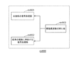
- FIG. 31 is a diagram showing a configuration for switching the drive frequency.
- FIG. 32 is a diagram showing the steps of identifying video data and switching the drive frequency.
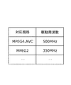
- FIG. 33 is a diagram showing an example of a look-up table in which video data standards and drive frequencies are associated with each other.
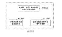
- FIG. 34A is a diagram illustrating an example of a configuration in which modules of the signal processing unit are shared.
- FIG. 34B is a diagram illustrating another example of the configuration for sharing the modules of the signal processing unit.
- the current HEVC standard includes a process called SAO (Sample Adaptive Offset).
- SAO Sample Adaptive Offset
- the SAO process is a process of adding an offset value to each pixel of an image decoded from a code string. Thereby, the original image before encoding can be reproduced more faithfully, and the image quality deterioration due to the encoding can be reduced.
- the image coding apparatus selects a context for each signal to be coded. Then, the symbol occurrence probability is determined corresponding to the selected context.
- the inventors have found that the conventional method has a problem that the number of contexts used in arithmetic coding is large, and a memory of a large size must be prepared to save the context.
- an image encoding method includes an SAO processing step of performing sample adaptive offset (SAO) processing on a luminance signal, a chrominance Cb signal, and a chrominance Cr signal included in a processing target block.
- SAO sample adaptive offset
- a first flag arithmetically coding a first flag indicating whether the SAO parameter indicating the content of the SAO process is the same for the processing target block and the left adjacent block left adjacent to the processing target block;
- the luminance signal, the chrominance Cb signal, and the chrominance C Arithmetic coded using one context the first flag for the signal.
- the image coding method arithmetically codes the first flag for the luminance signal, the chrominance Cb signal, and the chrominance Cr signal using one context.
- the image coding method can reduce the number of contexts used as compared to the case where the first flag for the luminance signal, the chrominance Cb signal, and the chrominance Cr signal is arithmetically encoded using different contexts, and The throughput can be reduced.
- the said image coding method can reduce processing amount, suppressing the fall of coding efficiency.
- the image coding method may further arithmetically code a second flag indicating whether the SAO parameter is the same for the processing target block and the upper adjacent block above and adjacent to the processing target block.
- the second flag encoding step, the first flag encoding step and the second flag encoding step including a context used for arithmetic coding of the first flag and an arithmetic coding of the second flag
- the context may be determined according to the same context determination method.
- the said image coding method can share a circuit with a 1st flag and a 2nd flag by using the same context determination method with respect to a 1st flag and a 2nd flag. Thereby, simplification of the image coding apparatus can be realized.
- a luminance first flag which is a first flag for the luminance signal
- a Cb first flag which is a first flag for the chrominance Cb signal
- the chrominance Cr signal The Cr first flag, which is the first flag for, may be arithmetically encoded using one context.
- a single first flag for the luminance signal, the chrominance Cb signal and the chrominance Cr signal may be arithmetically encoded using one context.
- each pixel included in the processing target block is classified into a plurality of categories, an offset value associated with the classified category is added to each pixel, and the SAO parameter is a category And information indicating an offset value.
- SAO parameters indicating contents of SAO (Sample Adaptive Offset) processing are the same for the processing target block and the left adjacent block left adjacent to the processing target block.
- the said image decoding method carries out the arithmetic decoding of the 1st flag for a luminance signal, a colour-difference Cb signal, and a colour-difference Cr signal using one context.
- the image decoding method can reduce the number of contexts used compared to the case where the first flag for the luminance signal, the chrominance Cb signal, and the chrominance Cr signal is arithmetically decoded using different contexts, and the processing amount Can be reduced.
- the image decoding method can reduce the amount of processing while suppressing a decrease in coding efficiency.
- the image decoding method further performs arithmetic decoding of a second flag indicating whether the SAO parameter is the same for the process target block and the upper adjacent block above and adjacent to the process target block.
- the same context is determined as the context used for arithmetic decoding of the first flag and the context used for arithmetic decoding of the second flag. It may be determined according to the method.
- the image decoding method can share the circuit with the first flag and the second flag by using the same context determination method for the first flag and the second flag. Thereby, simplification of the image decoding apparatus can be realized.
- a luminance first flag which is a first flag for the luminance signal
- a Cb first flag which is a first flag for the chrominance Cb signal
- the chrominance Cr signal The first flag, the Cr first flag, may be arithmetically decoded using one context.
- a single first flag for the luminance signal, the chrominance Cb signal, and the chrominance Cr signal may be arithmetically decoded using one context.
- each pixel included in the processing target block is classified into a plurality of categories, an offset value associated with the classified category is added to each pixel, and the SAO parameter is a category And information indicating an offset value.
- An image coding apparatus includes a control circuit and a storage device accessible from the control circuit, and the control circuit includes a luminance signal, a chrominance Cb signal, and a chrominance signal included in a processing target block.
- An SAO processing step of performing SAO (Sample Adaptive Offset) processing on a chrominance Cr signal, and an SAO parameter indicating contents of the SAO processing are the same for the processing target block and a left adjacent block adjacent to the processing target block on the left.
- the SAO parameter of the processing target block is arithmetically processed. And encoding the SAO parameter encoding step; The grayed encoding step, arithmetic coding using one context the first flag for a luminance signal, color difference Cb signal and a color difference Cr signal.
- the image coding apparatus arithmetically codes the first flag for the luminance signal, the chrominance Cb signal, and the chrominance Cr signal using one context.
- the image coding apparatus can reduce the number of contexts used as compared to the case where the first flag for the luminance signal, the chrominance Cb signal and the chrominance Cr signal is arithmetically encoded using different contexts, and The throughput can be reduced.
- the image coding apparatus can reduce the amount of processing while suppressing a decrease in coding efficiency.
- An image decoding apparatus includes a control circuit and a storage device accessible from the control circuit, and the control circuit is a SAO parameter indicating the content of SAO (Sample Adaptive Offset) processing.
- an SAO parameter decoding step of arithmetically decoding the SAO parameter of the process target block, and the first flag obtained by arithmetic decoding The SAO parameter of the processing target block or the left adjacent block
- the image decoding apparatus arithmetically decodes the luminance signal, the chrominance Cb signal, and the first flag for the chrominance Cr signal using one context.
- the image decoding apparatus can reduce the number of contexts used compared to the case where the first flag for the luminance signal, the chrominance Cb signal, and the chrominance Cr signal is arithmetically decoded using different contexts, and the processing amount Can be reduced.
- the image decoding apparatus can reduce the amount of processing while suppressing a decrease in encoding efficiency.
- An image coding and decoding apparatus includes the image coding apparatus and the image decoding apparatus.
- Embodiment 1 In the present embodiment, an embodiment of the image coding apparatus will be described.
- FIG. 1 is a block diagram showing the configuration of an image coding apparatus 100 according to the present embodiment.
- the image coding apparatus 100 shown in FIG. 1 generates a code string 125 (coded bit stream) by coding the input image 121.
- the image coding apparatus 100 includes a code block division unit 101, a subtraction unit 102, a conversion unit 103, a coefficient variable length coding unit 104, an inverse conversion unit 105, an addition unit 106, and a frame memory 107.
- a prediction unit 108, an SAO processing unit 109, and an SAO parameter variable length coding unit 110 are provided.
- Step S101 The code block division unit 101 divides the input image 121 into code blocks 122, and sequentially outputs the code blocks 122 to the subtraction unit 102 and the prediction unit 108.
- the size of the code block 122 is variable, and the code block division unit 101 divides the input image 121 into code blocks 122 using features of the input image 121.
- the minimum size of the code block 122 is 4 horizontal pixels ⁇ 4 vertical pixels, and the maximum size is 32 horizontal pixels ⁇ 32 vertical pixels.
- Step S102 The prediction unit 108 generates a prediction block 129 using the code block 122 and the decoded image 128 stored in the frame memory 107.
- Step S103 The subtraction unit 102 generates a difference block 123 which is a difference between the code block 122 and the prediction block 129.
- Step S104 The conversion unit 103 converts the difference block 123 into a frequency coefficient 124.
- Step S105 The inverse conversion unit 105 restores the difference block 126 by converting the frequency coefficient 124 into pixel data.
- Step S106 The addition unit 106 generates a decoded block 127 by adding the restored difference block 126 and the prediction block 129.
- the SAO processing unit 109 determines the SAO parameter 131 and adds the SAO offset value to each pixel of the decoded block 127 according to the determined SAO parameter to generate a decoded block 130, and adds the decoded block 130 as the addition result to the frame. It is stored in the memory 107.
- the SAO processing unit 109 classifies each pixel into a plurality of categories, and adds an offset value corresponding to the classified category to each pixel. There are multiple classification methods.
- the SAO processing unit 109 generates sao_type_idx, which is a parameter indicating the used classification method, and sao_offset indicating an offset value as the SAO parameter 131.
- the SAO processing unit 109 sets sao_merge_left_flag to that effect to 1.
- Step S108 The SAO parameter variable-length coding unit 110 generates a code string 125 by variable-length coding the SAO parameter 131. Details will be described later.
- Step S109 The coefficient variable length coding unit 104 generates a code string 125 by performing variable length coding on the frequency coefficient 124.
- Step S110 Steps S102 to S109 are repeated until encoding of all code blocks in the image to be encoded is completed.
- FIG. 3 is a block diagram showing the configuration of the SAO parameter variable length coding unit 110.
- the SAO parameter variable-length coding unit 110 includes a sao_merge_left_flag coding unit 141, a sao_type_idx coding unit 142, and a sao_offset coding unit 143.
- Step S121 The sao_merge_left_flag encoding unit 141 encodes sao_merge_left_flag. Steps S121 to S124 are executed for each of the luminance component Y (luminance signal), the color difference component Cb (color difference Cb signal), and the color difference component Cr (color difference Cr signal). That is, steps S121 to S124 are performed three times.
- the luminance component Y, the color difference component Cb, and the color difference component Cr will also be referred to as Y, Cb and Cr.
- Step S122 The SAO parameter variable-length coding unit 110 determines whether sao_merge_left_flag is 1 and, if sao_merge_left_flag is 1, does not encode sao_type_idx and sao_offset, and proceeds to step S125. On the other hand, if sao_merge_left_flag is 0, the SAO parameter variable-length coding unit 110 proceeds to step S123.
- Step S123 The sao_type_idx encoding unit 142 encodes sao_type_idx.
- Step S124 The sao_offset encoding unit 143 encodes sao_offset.
- Step S125 Steps S121 to S124 are repeated until the encoding of the SAO parameters of Y, Cb and Cr is completed.
- FIG. 5 is a block diagram showing the configuration of the sao_merge_left_flag encoding unit 141.
- the sao_merge_left_flag encoding unit 141 includes a context switching unit 151, a context 0 arithmetic encoding unit 152, and a context 1 arithmetic encoding unit 153.
- Step S131 The context switching unit 151 determines whether sao_merge_left_flag to be processed is sao_merge_left_flag of luminance component Y, and if sao_merge_left_flag to be processed is sao_merge_left_flag to be luminance component Y, the process proceeds to step S132 and sao_merge_left_flag to be processed is Cb or Cr sao_merge_left_flag If there is, the process proceeds to step S133.
- Step S132 The context 0 arithmetic coding unit 152 generates a code string by performing arithmetic coding on sao_merge_left_flag using the context 0.
- Step S133 The context 1 arithmetic coding unit 153 performs arithmetic coding on sao_merge_left_flag using context 1 to generate a code string.
- the sao_merge_left_flag encoding unit 141 performs arithmetic encoding of sao_merge_left_flag using two types of contexts of context 0 and context 1.
- the sao_merge_left_flag encoding unit 141 uses context 0 exclusively for sao_merge_left_flag of luminance component Y, but uses context 1 in common for sao_merge_left_flag of chrominance component Cb and sao_merge_left_flag of chrominance component Cr. .
- the image coding apparatus 100 uses the same context for sao_merge_left_flag of Cb and Cr in arithmetic coding of sao_merge_left_flag. Thereby, the image coding apparatus 100 can reduce the number of contexts and the memory size. Further, context switching between Cb and Cr becomes unnecessary, and determination processing of Cb and Cr can be deleted.
- the symbol occurrence probability (probability of becoming 1) of sao_merge_left_flag is considered to be different between Cb and Cr, and different contexts are used.
- the inventor has found through experiments that sao_merge_left_flag of Cb and Cr is correlated, and that coding efficiency is hardly deteriorated even if the context is common.
- FIG. 7 is a flowchart of an image coding method by the image coding apparatus 100 in this case.
- the image coding apparatus 100 performs SAO processing on each of the luminance signal, the color difference Cb signal, and the color difference Cr signal included in the processing target block (S141). Specifically, the image coding apparatus 100 classifies each pixel included in the processing target block into a plurality of categories, and adds the offset value associated with the classified category to each pixel. Further, the SAO parameter includes information (sao_type_idx) indicating the category classification method and information (sao_offset) indicating the offset value.
- the category classification method is, for example, a band offset method of classifying pixels by the value of pixel value, an edge offset method of classifying pixels by edge direction, or the like. Moreover, sao_type_idx may further indicate whether or not to perform SAO processing.
- the image coding apparatus 100 sets a first flag (sao_merge_left_flag) indicating whether the SAO parameter indicating the content of the SAO process is the same for the processing target block and the left adjacent block adjacent to the processing target block on the left. ) Is arithmetically encoded (S142).
- the image coding apparatus 100 arithmetically codes the first flag for the luminance signal, the chrominance Cb signal, and the chrominance Cr signal using one context.
- the context is a table indicating symbol occurrence probability, and is updated according to the actually appearing symbol.
- the image coding apparatus 100 arithmetically calculates the SAO parameter of the processing target block. It encodes (S144).
- the image coding apparatus 100 performs SAO processing of the processing target block. Do not arithmetic encode the parameters.
- FIG. 8 shows the experimental results of the image coding method according to Embodiment 1 (a method using a common context for Cb and Cr) and the method using a common context for Y, Cb and Cr (Modification 1).
- FIG. The experimental conditions follow the common experimental conditions of the HEVC standardization body. The larger the value, the lower the coding efficiency, and the negative the value, the better the coding efficiency. As shown in FIG. 8, all values are 0.1% or less, and it can be seen that the coding efficiency hardly decreases even if the number of contexts is reduced by using a common context. In addition, in the first modification, a part of the value is ⁇ 0.3%, which indicates that the coding efficiency is improved.
- the method of the present embodiment or the method of the first modification may be applied to other syntaxes given to the code string, not limited to sao_merge_left_flag. That is, a common variable-length coding unit may be used for sao_merge_left_flag and the other syntaxes.
- the image coding apparatus 100 uses a flag sao_merge_up_flag indicating whether to copy and use the SAO parameter of an adjacent upper code block, and uses a common context for Cb and Cr for that flag, or Y, A common context may be used for Cb and Cr.
- the image coding apparatus 100 uses the second flag (sao_merge_up_flag) indicating whether the SAO parameter indicating the content of the SAO process is the same for the processing target block and the upper adjacent block above and adjacent to the processing target block. Arithmetic coding Also, the image coding apparatus 100 determines the context used for arithmetic coding of the first flag and the context used for arithmetic coding of the second flag according to the same context determination method.
- the context determination method is, for example, a method of using a common context with Cb and Cr, or a method of using a common context with Y, Cb and Cr, as described above.
- the image coding apparatus 100 uses sao_type_idx indicating the classification type and sao_offset indicating the SAO offset value as the SAO parameters, but the configuration is not limited thereto.
- the SAO parameter may further include at least one of a parameter used as auxiliary information for classifying pixels, and sao_offset_sign representing a sign (positive or negative) bit of sao_offset.
- the image coding apparatus 100 codes the SAO parameter for each code block, but it is not limited thereto.
- the image coding apparatus 100 may code the SAO parameter in units smaller than the code block, or conversely may code the SAO parameter in units in which a plurality of code blocks are connected.
- the image coding apparatus 100 may copy and use the SAO parameter of another code block without coding the SAO parameter in the target code block.
- the code block is 32 ⁇ 32 at the maximum and 4 ⁇ 4 the minimum, the size of the coding block is not limited to this. Also, the code block may have a fixed size.
- the image coding apparatus 100 includes the luminance first flag which is the first flag for the luminance signal, the Cb first flag which is the first flag for the chrominance Cb signal, and the first for the chrominance Cr signal. Arithmetic coding is performed using one context with the Cr first flag that is the flag.
- one common sao_merge_left_flag may be generated for Y, Cb and Cr. Even in such a case, a common (one) context is used for sao_merge_left_flag of Y, Cb and Cr as in the above embodiment. That is, the image coding apparatus 100 may arithmetically code a single first flag for the luminance signal, the chrominance Cb signal, and the chrominance Cr signal using one context.
- processing in the present embodiment may be realized by software. Then, this software may be distributed by downloading or the like. Also, the software may be distributed by being recorded on a recording medium such as a CD-ROM. This applies to the other embodiments in the present specification.
- an image decoding apparatus 200 that decodes the coded bit stream generated by the image coding apparatus 100 according to the first embodiment will be described.
- FIG. 9 is a block diagram showing a configuration of image decoding apparatus 200 according to the present embodiment.
- the image decoding apparatus 200 illustrated in FIG. 9 generates a decoded image 225 by decoding the code string 221.
- the code string 221 corresponds to, for example, the code string 125 generated by the image coding apparatus 100 described above.
- the image decoding apparatus 200 includes a coefficient variable length decoding unit 201, an inverse conversion unit 202, an addition unit 203, a decoded block combining unit 204, a frame memory 205, an SAO parameter variable length decoding unit 206, and an SAO processing unit. And 207.
- Step S201 The SAO parameter variable length decoding unit 206 performs variable length decoding of the SAO parameter 227 from the code string 221.
- Step S202 The coefficient variable length decoding unit 201 performs variable length decoding on the code string 221 to generate a frequency coefficient 222, and outputs the frequency coefficient 222 to the inverse transform unit 202.
- Step S203 The inverse conversion unit 202 generates the difference block 223 by converting the frequency coefficient 222 into pixel data.
- Step S204 The addition unit 203 generates a decoded block 224 by adding the decoded image 226 stored in the frame memory 205 and the difference block 223.
- Step S205 The SAO processing unit 207 classifies each pixel of the decoded block 224 into categories according to the SAO parameter 227, and generates an decoded block 228 by adding an offset value corresponding to the category to each pixel.
- Step S206 Steps S201 to S205 are repeated until decoding of all decoded blocks in the image to be decoded is completed.
- the decoded block combining unit 204 combines the plurality of decoded blocks 228 to generate the decoded image 225, and stores the decoded image 225 as the decoded image 226 in the frame memory 205.
- FIG. 11 is a block diagram showing the configuration of the SAO parameter variable length decoding unit 206.
- the SAO parameter variable length decoding unit 206 includes a sao_merge_left_flag decoding unit 241, a sao_type_idx decoding unit 242, and a sao_offset decoding unit 243.
- FIG. 12 is a diagram showing a flow of SAO parameter variable length decoding processing (S201 in FIG. 10).
- the SAO parameter variable length decoding process shown in FIG. 12 is the same as the SAO parameter variable length coding process shown in FIG.
- the SAO parameter variable-length decoding unit 206 does not decode sao_type_idx and sao_offset, but copies the SAO parameter of the already adjacent decoded code block on the left and performs SAO processing.
- Step S221 The sao_merge_left_flag decoding unit 241 decodes sao_merge_left_flag. Steps S221 to S224 are performed on each of the luminance component Y, the color difference component Cb, and the color difference component Cr. That is, steps S221 to S224 are performed three times.
- Step S222 The SAO parameter variable-length decoding unit 206 determines whether sao_merge_left_flag is 1, and if sao_merge_left_flag is 1, does not decode sao_type_idx and sao_offset, and the process proceeds to step S225. On the other hand, when sao_merge_left_flag is 0, the SAO parameter variable-length decoding unit 206 proceeds to step S223.
- Step S223 The sao_type_idx decoding unit 242 decodes sao_type_idx.
- Step S224 The sao_offset decoding unit 243 decodes sao_offset.
- Step S225 Steps S221 to S224 are repeated until decoding of the SAO parameters of Y, Cb and Cr is completed.
- FIG. 13 is a block diagram showing the configuration of the sao_merge_left_flag decoding unit 241. As shown in FIG. As shown in FIG. 13, the sao_merge_left_flag decoding unit 241 includes a context switching unit 251, a context 0 arithmetic decoding unit 252, and a context 1 arithmetic decoding unit 253.
- FIG. 14 is a diagram showing a flow of sao_merge_left_flag decoding processing (S221 in FIG. 12).
- the sao_merge_left_flag decoding process shown in FIG. 14 is only that the part of encoding in the sao_merge_left_flag encoding process shown in FIG. 6 of the first embodiment has been changed to decoding.
- Step S231 The context switching unit 251 determines whether the processing object sao_merge_left_flag is sao_merge_left_flag of the luminance component Y, and if the processing object sao_merge_left_flag is the luminance component Y sao_merge_left_flag, the process goes to step S232, and the processing object sao_merge_left_flag is Cb or Cr sao_merge_left_flag If there is, the process proceeds to step S233.
- Step S232 The context 0 arithmetic decoding unit 252 generates a code string by performing arithmetic decoding on sao_merge_left_flag using the context 0.
- Step S233 The context 1 arithmetic decoding unit 253 generates a code string by performing arithmetic decoding on sao_merge_left_flag using the context 1.
- the sao_merge_left_flag decoding unit 241 performs arithmetic decoding on sao_merge_left_flag using two types of contexts of context 0 and context 1.
- the sao_merge_left_flag decoding unit 241 uses context 0 exclusively for sao_merge_left_flag of the luminance component Y, but uses context 1 commonly for sao_merge_left_flag of the chrominance component Cb and sao_merge_left_flag of the chrominance component Cr.
- the image decoding apparatus 200 can achieve the same effect as that of the first embodiment.
- the image decoding apparatus 200 uses a common context for Cb and Cr, but may use a common context for Y, Cb, and Cr.
- FIG. 15 is a flowchart of an image decoding method by the image decoding apparatus 200 in this case.
- the image decoding apparatus 200 indicates whether the SAO parameter indicating the content of the SAO process is the same for the processing target block and the left adjacent block on the left adjacent to the processing target block. Arithmetic decoding of the flag (sao_merge_left_flag) is performed (S241). Here, the image decoding apparatus 200 performs arithmetic decoding on the luminance signal, the chrominance Cb signal, and the first flag for the chrominance Cr signal using one context.
- the image decoding apparatus 200 Arithmetic decoding is performed on the SAO parameters of the processing target block (S 243).
- the image decoding apparatus 200 uses the SAO parameter of the processing target block obtained by arithmetic decoding or the SAO parameter of the left adjacent block according to the first flag to use the luminance signal and the color difference Cb included in the processing target block.
- An SAO process is performed on each of the signal and the chrominance Cr signal (S244).
- the image decoding apparatus 200 uses the SAO parameter of the processing target block obtained by the arithmetic decoding when the first flag is “0”, and the left adjacent when the second flag is “1”.
- the SAO parameter includes information (sao_type_idx) indicating the category classification method and information (sao_offset) indicating the offset value.
- the image decoding apparatus 200 classifies each pixel included in the target block into a plurality of categories using the category classification method indicated by sao_type_idx. Then, the image decoding apparatus 200 adds, to each pixel, an offset value associated with the classified category. This offset value is indicated by sao_offset.
- the image decoding apparatus 200 determines whether the SAO parameter indicating the content of the SAO process is the same for the processing target block and the upper adjacent block above and adjacent to the processing target block.
- the second flag (sao_merge_up_flag) may be arithmetically decoded.
- the image decoding apparatus 200 may determine the context used for arithmetic decoding of the first flag and the context used for arithmetic decoding of the second flag according to the same context determination method.
- the image decoding apparatus 200 includes a luminance first flag which is a first flag for a luminance signal, a Cb first flag which is a first flag for a chrominance Cb signal, and a first flag for a chrominance Cr signal.
- a certain Cr first flag may be arithmetically decoded using one context.
- the image decoding apparatus 200 may arithmetically decode a single first flag for a luminance signal, a chrominance Cb signal, and a chrominance Cr signal using one context.
- each of the functional blocks can usually be realized by an MPU (microprocessor), a memory, and the like. Further, the processing by each of the functional blocks can usually be realized by software (program), and the software is stored in a storage medium such as a ROM. Then, such software may be distributed by downloading or the like, or may be distributed by being recorded on a recording medium such as a CD-ROM. Of course, it is also possible to realize each functional block by hardware (dedicated circuit).
- each embodiment may be realized by centralized processing using a single device (system), or may be realized by distributed processing using a plurality of devices. Good.
- the computer that executes the program may be singular or plural. That is, the computer may perform centralized processing or may perform distributed processing.
- each processing unit included in the image encoding device and the image decoding device according to the above embodiments is typically realized as an LSI which is an integrated circuit. These may be individually made into one chip, or may be made into one chip so as to include some or all.
- circuit integration is not limited to LSI's, and implementation using dedicated circuitry or general purpose processors is also possible.
- a field programmable gate array (FPGA) that can be programmed after LSI fabrication, or a reconfigurable processor that can reconfigure connection and setting of circuit cells inside the LSI may be used.
- each component may be configured by dedicated hardware or implemented by executing a software program suitable for each component.
- Each component may be realized by a program execution unit such as a CPU or a processor reading and executing a software program recorded on a recording medium such as a hard disk or a semiconductor memory.
- the image encoding device and the image decoding device include a control circuit (control circuit) and a storage (electrically accessible from the control circuit) electrically connected to the control circuit.
- the control circuit includes at least one of dedicated hardware and a program execution unit.
- the storage device stores a software program to be executed by the program execution unit.
- the present invention may be the above software program, or may be a non-transitory computer readable recording medium in which the above program is recorded. Further, it goes without saying that the program can be distributed via a transmission medium such as the Internet.
- division of functional blocks in the block diagram is an example, and a plurality of functional blocks may be realized as one functional block, one functional block may be divided into a plurality of parts, or some functions may be transferred to another function block. May be Also, a single piece of hardware or software may process the functions of a plurality of functional blocks having similar functions in parallel or in time division.
- the order in which the steps included in the above-described image encoding method or image decoding method are performed is for illustrating the present invention specifically, and may be an order other than the above. . Also, some of the above steps may be performed simultaneously (in parallel) with other steps.
- Each of the above-described embodiments can be implemented by recording a program for realizing the configuration of the moving picture coding method (image coding method) or the moving picture decoding method (image decoding method) described in each of the above embodiments on a storage medium. It is possible to easily carry out the processing shown in the form in an independent computer system.
- the storage medium may be a magnetic disk, an optical disk, a magneto-optical disk, an IC card, a semiconductor memory, or the like as long as the program can be recorded.
- the system is characterized by having an image coding / decoding device including an image coding device using an image coding method and an image decoding device using an image decoding method.
- Other configurations in the system can be suitably modified as the case may be.
- FIG. 16 is a diagram showing an overall configuration of a content supply system ex100 for realizing content distribution service.
- the area for providing communication service is divided into desired sizes, and base stations ex106, ex107, ex108, ex109 and ex110, which are fixed wireless stations, are installed in each cell.
- This content supply system ex100 includes a computer ex111, a personal digital assistant (PDA) ex112, a camera ex113, a mobile phone ex114, and a game machine ex115 via the Internet service provider ex102 and the telephone network ex104 and the base stations ex106 to the Internet ex101. Each device such as is connected.
- PDA personal digital assistant
- content supply system ex100 is not limited to the configuration as shown in FIG. 16, and any element may be combined and connected.
- each device may be directly connected to the telephone network ex104 without going through the base stations ex106 to ex110, which are fixed wireless stations.
- the devices may be directly connected to each other via near field communication or the like.
- the camera ex113 is a device capable of shooting moving images such as a digital video camera
- the camera ex116 is a device capable of shooting still images and moving images such as a digital camera.
- the mobile phone ex114 is a GSM (registered trademark) (Global System for Mobile Communications) system, a CDMA (Code Division Multiple Access) system, a W-CDMA (Wideband-Code Division Multiple Access) system, or an LTE (Long Term Evolution) system.
- the method may be any of HSPA (High Speed Packet Access) mobile phone, PHS (Personal Handyphone System), etc.
- live distribution and the like become possible by connecting the camera ex113 and the like to the streaming server ex103 through the base station ex109 and the telephone network ex104.
- live distribution encoding processing is performed on content (for example, a video of a music live, etc.) captured by the user using camera ex113 as described in the above embodiments (that is, according to one aspect of the present invention) Function as the image coding apparatus), and transmits to the streaming server ex103.
- the streaming server ex 103 streams the content data transmitted to the requested client.
- the clients include the computer ex 111, the PDA ex 112, the camera ex 113, the mobile phone ex 114, the game machine ex 115 and the like capable of decoding the above-mentioned encoded data.
- Each device that has received the distributed data decodes and reproduces the received data (that is, it functions as an image decoding apparatus according to an aspect of the present invention).
- encoding processing of captured data may be performed by the camera ex 113, may be performed by the streaming server ex 103 that performs data transmission processing, or may be performed sharing each other.
- the decryption processing of the data distributed may be performed by the client, may be performed by the streaming server ex 103, or may be performed sharing each other.
- not only the camera ex113 but also still images and / or moving image data captured by the camera ex116 may be transmitted to the streaming server ex103 via the computer ex111.
- the encoding process in this case may be performed by any of the camera ex 116, the computer ex 111, and the streaming server ex 103, or may be performed sharing each other.
- these encoding / decoding processes are generally processed by the LSI ex 500 that the computer ex 111 or each device has.
- the LSI ex 500 may be a single chip or a plurality of chips.
- Software for moving image encoding / decoding is incorporated in any recording medium (CD-ROM, flexible disk, hard disk, etc.) readable by computer ex111 etc., and encoding / decoding processing is performed using the software. May be Furthermore, when the mobile phone ex114 is equipped with a camera, moving image data acquired by the camera may be transmitted. The moving image data at this time is data encoded by the LSI ex 500 included in the mobile phone ex 114.
- the streaming server ex103 may be a plurality of servers or a plurality of computers, and may process, record, or distribute data in a distributed manner.
- the client can receive and reproduce the encoded data.
- the client can receive, decrypt, and reproduce the information transmitted by the user in real time, and even a user who does not have special rights or facilities can realize personal broadcasting.
- the system for digital broadcasting ex200 also includes at least a moving picture coding apparatus (image coding apparatus) or a moving picture decoding of each of the above embodiments. Any of the devices (image decoding devices) can be incorporated.
- a moving picture coding apparatus image coding apparatus
- Any of the devices (image decoding devices) can be incorporated.
- multiplexed data in which music data and the like are multiplexed with video data is transmitted to the communication or satellite ex202 via radio waves.
- This video data is data encoded by the moving picture encoding method described in each of the above embodiments (that is, data encoded by the image encoding apparatus according to one aspect of the present invention).
- the broadcast satellite ex202 receiving this transmits a radio wave for broadcasting, and this radio wave is received by a home antenna ex204 capable of receiving satellite broadcasting.
- a device such as a television (receiver) ex300 or a set top box (STB) ex217 decodes and reproduces the received multiplexed data (that is, it functions as an image decoding device according to an aspect of the present invention).
- the reader / recorder ex218 reads and decodes multiplexed data recorded on a recording medium ex215 such as a DVD or BD, or encodes a video signal on the recording medium ex215 and, in some cases, multiplexes it with a music signal and writes it. It is possible to implement the moving picture decoding apparatus or the moving picture coding apparatus described in each of the above embodiments. In this case, the reproduced video signal is displayed on the monitor ex 219, and the video signal can be reproduced in another apparatus or system by the recording medium ex 215 on which the multiplexed data is recorded.
- the moving picture decoding apparatus may be mounted in the set top box ex217 connected to the cable ex203 for cable television or the antenna ex204 for satellite / terrestrial broadcast, and this may be displayed on the monitor ex219 of the television. At this time, the moving picture decoding apparatus may be incorporated in the television instead of the set top box.
- FIG. 18 is a diagram showing a television (receiver) ex300 that uses the moving picture decoding method and the moving picture coding method described in each of the above embodiments.
- the television ex300 acquires a tuner ex301 that acquires or outputs multiplexed data in which audio data is multiplexed into video data via the antenna ex204 that receives the broadcast, the cable ex203, or the like, and demodulates the received multiplexed data.
- the modulation / demodulation unit ex302 that modulates multiplexed data to be transmitted to the outside, the demodulated multiplexed data is separated into video data and audio data, or the video data and audio data encoded by the signal processing unit ex306 And a multiplexing / demultiplexing unit ex303 that multiplexes
- the television ex300 decodes the audio data and the video data, or encodes the respective information.
- the audio signal processing unit ex304, the video signal processing unit ex305 (an image coding apparatus or an image according to an aspect of the present invention And a speaker ex307 for outputting a decoded audio signal, and an output unit ex309 having a display unit ex308 such as a display for displaying a decoded video signal.
- the television ex300 includes an interface unit ex317 including an operation input unit ex312 and the like that receive an input of a user operation.
- the television ex300 includes a control unit ex310 that centrally controls each unit, and a power supply circuit unit ex311 that supplies power to each unit.
- the interface unit ex317 is, besides the operation input unit ex312, a bridge ex313 connected to an external device such as a reader / recorder ex218, a slot unit ex314 for enabling attachment of a recording medium ex216 such as an SD card, external recording such as a hard disk It may have a driver ex 315 for connecting to a medium, a modem ex 316 connected to a telephone network, and the like. Note that the recording medium ex216 can electrically record information by a nonvolatile / volatile semiconductor memory element to be stored.
- the components of the television ex300 are connected to one another via a synchronization bus.
- television ex300 decodes multiplexed data acquired from the outside by antenna ex204 and the like and reproduces the multiplexed data.
- the television ex300 receives the user operation from the remote controller ex220 and the like, and demultiplexes the multiplexed data demodulated by the modulation / demodulation unit ex302 by the multiplexing / demultiplexing unit ex303 based on the control of the control unit ex310 having a CPU or the like. Further, the television ex300 decodes the separated audio data in the audio signal processing unit ex304, and decodes the separated video data in the video signal processing unit ex305 using the decoding method described in each of the above embodiments.
- the decoded audio signal and video signal are output from the output unit ex309 to the outside. At the time of output, these signals may be temporarily stored in the buffers ex318, ex319, etc. so that the audio signal and the video signal are reproduced synchronously. Also, the television ex300 may read multiplexed data not from broadcast or the like, but from the recording media ex215 and ex216 such as a magnetic / optical disk and an SD card. Next, a configuration will be described in which the television ex300 encodes an audio signal or a video signal and externally transmits the signal or writes the signal to a recording medium or the like.
- the television ex300 receives the user operation from the remote controller ex220 and the like, and based on the control of the control unit ex310, encodes the audio signal by the audio signal processing unit ex304, and the video signal processing unit ex305 executes the video signal in each of the above embodiments. Coding is performed using the coding method described above.
- the encoded audio signal and video signal are multiplexed by multiplexer / demultiplexer ex303 and output to the outside. At the time of multiplexing, these signals may be temporarily stored in the buffers ex320, ex321, etc. so that the audio signal and the video signal are synchronized.
- the buffers ex318, ex319, ex320, and ex321 may have a plurality of buffers as illustrated, or one or more buffers may be shared. Furthermore, besides being illustrated, data may be stored in a buffer as a buffer material to avoid system overflow and underflow, for example, between the modulation / demodulation unit ex302 and the multiplexing / demultiplexing unit ex303.
- television ex300 In addition to acquiring audio data and video data from broadcasts and recording media, etc., television ex300 is also configured to receive AV input from a microphone or a camera, and performs encoding processing on data acquired from them. It is also good. Although television ex300 is described here as a configuration capable of the above encoding processing, multiplexing, and external output, these processing can not be performed, and only the above reception, decoding processing, and external output are possible. It may be a configuration.
- the decoding process or the encoding process may be performed by any of the television ex300 and the reader / recorder ex218, or with the television ex300.
- the reader / recorder ex 218 may share each other.
- FIG. 19 shows a configuration of an information reproducing / recording unit ex400 in the case of reading or writing data from an optical disc.
- the information reproducing / recording unit ex400 includes elements ex401, ex402, ex403, ex404, ex405, ex406, and ex407 described below.
- the optical head ex401 irradiates a laser spot on the recording surface of the recording medium ex215 which is an optical disk to write information, detects reflected light from the recording surface of the recording medium ex215, and reads the information.
- the modulation recording unit ex402 electrically drives the semiconductor laser incorporated in the optical head ex401 and modulates the laser light according to the recording data.
- the reproduction / demodulation unit ex403 amplifies the reproduction signal obtained by electrically detecting the reflected light from the recording surface by the photodetector incorporated in the optical head ex401, separates and demodulates the signal component recorded in the recording medium ex215, and Play back information.
- the buffer ex 404 temporarily holds information to be recorded on the recording medium ex 215 and information reproduced from the recording medium ex 215.
- the disk motor ex405 rotates the recording medium ex215.
- the servo control unit ex406 moves the optical head ex401 to a predetermined information track while controlling the rotational drive of the disk motor ex405, and performs the laser spot tracking process.
- the system control unit ex407 controls the entire information reproducing / recording unit ex400.
- the system control unit ex407 uses various information held in the buffer ex404, and generates / adds new information as necessary.
- the modulation recording unit ex402 and the reproduction / demodulation unit This is realized by performing recording and reproduction of information through the optical head ex401 while cooperatively operating the servo control unit ex406.
- the system control unit ex 407 is configured by, for example, a microprocessor, and executes the processing of reading and writing by executing the program.
- the optical head ex401 may be configured to perform higher-density recording using near-field light.
- FIG. 20 shows a schematic view of a recording medium ex 215 which is an optical disc.
- a guide groove (groove) is formed in a spiral shape on the recording surface of the recording medium ex215, and in the information track ex230, address information indicating the absolute position on the disc is recorded in advance by the change of the groove shape.
- the address information includes information for specifying the position of the recording block ex231, which is a unit for recording data, and the apparatus for recording and reproduction reproduces the information track ex230 and reads the address information to specify the recording block.
- the recording medium ex215 includes a data recording area ex233, an inner circumference area ex232, and an outer circumference area ex234.
- An area used to record user data is data recording area ex233, and inner circumference area ex232 and outer circumference area ex234 arranged on the inner circumference or the outer circumference of data recording area ex233 are used for specific applications other than user data recording. Used.
- the information reproducing / recording unit ex400 reads / writes encoded audio data, video data, or multiplexed data obtained by multiplexing those data from / to the data recording area ex233 of such a recording medium ex215.
- an optical disc such as a single layer DVD or BD has been described as an example, but the optical disc is not limited to these, and may be an optical disc having a multilayer structure and capable of recording other than the surface.
- an optical disc with multi-dimensional recording / reproduction such as recording information in the same place of the disc using light of colors of different wavelengths, recording layers of different information from various angles, etc. It may be
- the digital broadcasting system ex200 it is possible to receive data from the satellite ex202 and the like by the car ex210 having the antenna ex205 and reproduce a moving image on a display device such as a car navigation system ex211 which the car ex210 has.
- the configuration of the car navigation system ex211 may be, for example, the configuration shown in FIG. 18 to which a GPS reception unit is added, and the same may be considered for the computer ex111, the mobile phone ex114, and the like.
- FIG. 21A is a diagram showing a mobile phone ex114 using the moving picture decoding method and the moving picture coding method described in the above embodiment.
- the mobile phone ex114 is an antenna ex350 for transmitting and receiving radio waves to and from the base station ex110, a video, a camera unit ex365 capable of taking a still image, a video taken by the camera unit ex365, a video received by the antenna ex350, etc.
- a display unit ex 358 such as a liquid crystal display that displays the decoded data.
- the cellular phone ex114 further includes a main unit including an operation key unit ex366, an audio output unit ex357 which is a speaker for outputting audio, an audio input unit ex356 which is a microphone for inputting audio, a photographed image, A memory unit ex367 that stores still images, recorded voices, or encoded data such as received images, still images, and mails or decoded data, or an interface unit with a recording medium that similarly stores data A certain slot portion ex364 is provided.
- the mobile phone ex114 controls the main control unit ex360 that integrally controls each unit of the main body unit including the display unit ex358 and the operation key unit ex366, while the power supply circuit unit ex361, the operation input control unit ex362, and the video signal processing unit ex355 , Camera interface unit ex363, LCD (Liquid Crystal Display) control unit ex359, modulation / demodulation unit ex352, multiplexing / demultiplexing unit ex353, audio signal processing unit ex354, slot unit ex364, and memory unit ex367 are mutually connected via bus ex370 ing.
- the main control unit ex360 that integrally controls each unit of the main body unit including the display unit ex358 and the operation key unit ex366, while the power supply circuit unit ex361, the operation input control unit ex362, and the video signal processing unit ex355 , Camera interface unit ex363, LCD (Liquid Crystal Display) control unit ex359, modulation / demodulation unit ex352, multiplexing / demultiplexing unit ex353, audio signal processing unit ex354,
- power supply circuit unit ex361 starts up cellular phone ex114 to an operable state by supplying power from the battery pack to each unit.
- the cellular phone ex114 converts the audio signal collected by the audio input unit ex356 into a digital audio signal by the audio signal processing unit ex354 in the voice communication mode. This is spread spectrum processed by the modulation / demodulation unit ex 352, subjected to digital-to-analog conversion processing and frequency conversion processing by the transmission / reception unit ex 351, and then transmitted through the antenna ex 350.
- the cellular phone ex114 In the voice communication mode, the cellular phone ex114 amplifies received data received via the antenna ex350, performs frequency conversion processing and analog-to-digital conversion processing, performs spectrum despreading processing in the modulation / demodulation unit ex352, and performs audio signal processing unit After converting into an analog voice signal by ex 354, this is output from the voice output unit ex 357.
- main control unit ex360 performs spread spectrum processing on text data in modulation / demodulation unit ex352, performs digital / analog conversion processing and frequency conversion processing in transmission / reception unit ex351, and transmits it to base station ex110 via antenna ex350.
- substantially the reverse processing is performed on the received data, and the result is output to display unit ex 358.
- the video signal processing unit ex 355 compresses the video signal supplied from the camera unit ex365 according to the moving picture coding method described in each of the above embodiments.
- the encoded that is, it functions as an image encoding device according to an aspect of the present invention
- encoded video data is sent to the multiplexing / demultiplexing unit ex353.
- the audio signal processing unit ex354 encodes an audio signal collected by the audio input unit ex356 while capturing a video, a still image and the like with the camera unit ex365, and sends the encoded audio data to the multiplexing / demultiplexing unit ex353 Do.
- the multiplexing / demultiplexing unit ex353 multiplexes the encoded video data supplied from the video signal processing unit ex355 and the encoded audio data supplied from the audio signal processing unit ex354 according to a predetermined method, and the result is obtained.
- the multiplexed data is subjected to spread spectrum processing by the modulation / demodulation unit (modulation / demodulation circuit unit) ex352, subjected to digital / analog conversion processing and frequency conversion processing by the transmission / reception unit ex351, and then transmitted via the antenna ex350.
- multiplexed data received via antenna ex350 is decoded
- the multiplexing / demultiplexing unit ex353 separates the multiplexed data into a bit stream of video data and a bit stream of audio data, and processes the video signal encoded through the synchronization bus ex370 into video signal processing.
- the encoded audio data is supplied to the unit ex 355 and is supplied to the audio signal processing unit ex 354.
- the video signal processing unit ex 355 decodes a video signal by decoding according to the moving picture decoding method corresponding to the moving picture coding method described in each of the above embodiments (that is, an image according to one aspect of the present invention) For example, the display unit ex358 displays a video and a still image included in a moving image file linked to a home page via the LCD control unit ex359.
- the audio signal processing unit ex 354 decodes the audio signal, and the audio output unit ex 357 outputs the audio.
- the terminal such as the mobile phone ex114 or the like is, like the television ex300, a transmitting terminal of only an encoder and a receiving terminal of only a decoder, in addition to a transmitting / receiving terminal having both an encoder and a decoder.
- a transmitting terminal of only an encoder and a receiving terminal of only a decoder in addition to a transmitting / receiving terminal having both an encoder and a decoder.
- reception and transmission of multiplexed data in which music data and the like are multiplexed in the video data in the digital broadcasting system ex200
- data in which text data related to the video and the like are multiplexed besides audio data It may be video data itself instead of multiplexed data.
- Embodiment 4 As necessary, the moving picture coding method or apparatus shown in each of the above embodiments and the moving picture coding method or apparatus conforming to different standards such as MPEG-2, MPEG4-AVC, VC-1 are switched as appropriate. It is also possible to generate video data.
- multiplexed data in which audio data and the like are multiplexed with video data is configured to include identification information indicating which standard the video data conforms to.
- identification information indicating which standard the video data conforms to.
- the specific configuration of multiplexed data including video data generated by the moving picture coding method or apparatus shown in each of the above embodiments will be described below.
- the multiplexed data is a digital stream in the MPEG-2 transport stream format.
- FIG. 22 shows the structure of multiplexed data.
- multiplexed data is obtained by multiplexing one or more of a video stream, an audio stream, a presentation graphics stream (PG), and an interactive graphics stream.
- the video stream indicates the main video and subvideo of the movie
- the audio stream (IG) indicates the subaudio mixing the main audio portion of the movie with the main audio
- the presentation graphics stream indicates the subtitles of the movie.
- the main video refers to a normal video displayed on the screen
- the sub video refers to a video displayed on a small screen in the main video.
- the interactive graphics stream also shows an interactive screen created by arranging GUI parts on the screen.
- the video stream is encoded by the moving picture coding method or apparatus shown in each of the above embodiments, or the moving picture coding method or apparatus complying with the conventional standards such as MPEG-2, MPEG4-AVC, VC-1 etc. ing.
- the audio stream is encoded by a method such as Dolby AC-3, Dolby Digital Plus, MLP, DTS, DTS-HD, or linear PCM.
- Each stream included in multiplexed data is identified by PID. For example, 0x1011 for video streams used for movie images, 0x1100 to 0x111F for audio streams, 0x1200 to 0x121F for presentation graphics, 0x1400 to 0x141F for interactive graphics streams, movie 0x1B00 to 0x1B1F are assigned to the video stream used for the sub video, and 0x1A00 to 0x1A1F are assigned to the audio stream used for the sub audio to be mixed with the main audio.
- FIG. 23 is a view schematically showing how multiplexed data is multiplexed.
- a video stream ex235 composed of a plurality of video frames and an audio stream ex238 composed of a plurality of audio frames are converted into PES packet sequences ex236 and ex239, respectively, and converted into TS packets ex237 and ex240.
- the data of presentation graphics stream ex241 and interactive graphics ex244 are converted to PES packet sequences ex242 and ex245, respectively, and further converted to TS packets ex243 and ex246.
- the multiplexed data ex247 is configured by multiplexing these TS packets into one stream.
- FIG. 24 shows in more detail how the video stream is stored in the PES packet sequence.
- the first row in FIG. 24 shows a video frame sequence of a video stream.
- the second row shows a PES packet sequence.
- I picture, B picture and P picture which are a plurality of Video Presentation Units in the video stream are divided for each picture and stored in the payload of the PES packet.
- Each PES packet has a PES header, and in the PES header, PTS (Presentation Time-Stamp) which is a picture display time and DTS (Decoding Time-Stamp) which is a picture decoding time are stored.
- PTS Presentation Time-Stamp
- DTS Decoding Time-Stamp
- FIG. 25 shows the format of a TS packet that is ultimately written to multiplexed data.
- the TS packet is a 188-byte fixed-length packet composed of a 4-byte TS header having information such as PID identifying a stream and a 184-byte TS payload storing data, and the PES packet is divided and stored in the TS payload. Ru.
- 4 bytes of TP_Extra_Header are attached to the TS packet, and a 192 byte source packet is configured and written to multiplexed data.
- TP_Extra_Header describes information such as ATS (Arrival_Time_Stamp).
- ATS indicates the transfer start time of the TS packet to the PID filter of the decoder.
- the source packets are arranged in the multiplexed data as shown in the lower part of FIG. 25, and the number incremented from the beginning of the multiplexed data is called an SPN (source packet number).
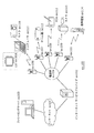
- TS packets included in multiplexed data there are PAT (Program Association Table), PMT (Program Map Table), PCR (Program Clock Reference), etc. in addition to each stream such as video, audio and subtitles.
- the PAT indicates what is the PID of the PMT used in multiplexed data, and the PID of the PAT itself is registered at 0.
- the PMT has PIDs of respective streams such as video, audio and subtitles included in multiplexed data and attribute information of streams corresponding to the PIDs, and also has various descriptors relating to multiplexed data.
- the descriptor includes copy control information for instructing permission or non-permission of copying of multiplexed data.
- the PCR corresponds to an ATS to which the PCR packet is transferred to the decoder in order to synchronize ATC (Arrival Time Clock), which is the ATS time axis, and STC (System Time Clock), which is the PTS ⁇ DTS time axis. It has STC time information.
- ATC Arriv Time Clock
- STC System Time Clock
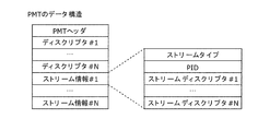
- FIG. 26 is a diagram for explaining in detail the data structure of the PMT.
- a PMT header in which the length of data included in the PMT, etc. is described is placed.
- a plurality of descriptors related to multiplexed data are arranged.
- the copy control information etc. is described as a descriptor.
- a plurality of stream information related to each stream included in the multiplexed data is disposed after the descriptor.
- the stream information is composed of a stream descriptor in which a stream type, a stream PID, and stream attribute information (frame rate, aspect ratio, etc.) are described in order to identify a stream compression codec and the like.
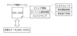
- the multiplexed data is recorded together with the multiplexed data information file.
- the multiplexed data information file is management information of multiplexed data as shown in FIG. 27.
- the multiplexed data information file has one-to-one correspondence with multiplexed data, and is composed of multiplexed data information, stream attribute information and an entry map.
- the multiplexed data information is composed of a system rate, a reproduction start time, and a reproduction end time.
- the system rate indicates the maximum transfer rate of multiplexed data to the PID filter of the system target decoder described later.
- the interval of ATS included in multiplexed data is set to be equal to or less than the system rate.
- the playback start time is the PTS of the leading video frame of multiplexed data
- the playback end time is set to the PTS of the video frame at the end of multiplexed data plus the playback interval of one frame.
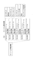
- attribute information on each stream included in multiplexed data is registered for each PID. Attribute information has different information for each video stream, audio stream, presentation graphics stream, and interactive graphics stream.
- the frame rate is determined by what compression codec the video stream is compressed, the resolution of the individual picture data making up the video stream, the aspect ratio, It has information such as how much it is.
- the audio stream attribute information is such as what compression codec the audio stream is compressed, what number of channels is included in the audio stream, what language it corresponds to, what sampling frequency is, etc. With the information of These pieces of information are used, for example, to initialize the decoder before the player reproduces.
- the stream type included in the PMT among the multiplexed data is used.
- video stream attribute information included in the multiplexed data information is used.
- the moving picture coding method or apparatus shown in each of the above embodiments for the stream type or video stream attribute information included in PMT.
- Providing a step or means for setting unique information indicating that the data is video data generated by the method or apparatus. With this configuration, it is possible to distinguish between video data generated by the moving picture coding method or apparatus described in each of the above embodiments and video data conforming to another standard.
- FIG. 29 shows steps of the moving picture decoding method according to the present embodiment.
- step exS100 the stream type included in the PMT or the video stream attribute information included in the multiplexed data information is acquired from the multiplexed data.
- step exS101 it is determined whether the stream type or the video stream attribute information indicates that it is multiplexed data generated by the moving picture coding method or apparatus shown in the above embodiments. Do.
- step exS102 each of the above implementations is performed. Decoding is performed by the moving picture decoding method shown in the form.
- the conventional Decoding is performed by a moving image decoding method conforming to the standard.
- FIG. 30 shows a configuration of an LSI ex 500 formed into one chip.
- the LSI ex500 includes elements ex501, ex502, ex503, ex504, ex505, ex506, ex507, ex508, and ex509 described below, and the elements are connected via a bus ex510.
- the power supply circuit unit ex505 starts up to an operable state by supplying power to each unit when the power is on.
- the LSI ex500 controls the microphone ex117 or the camera ex113 by the AV I / O ex509 based on the control of the control unit ex501 including the CPU ex502, the memory controller ex503, the stream controller ex504, and the drive frequency control unit ex512.
- the input AV signal is temporarily stored in an external memory ex 511 such as an SDRAM.
- the accumulated data is divided into plural times according to the processing amount and the processing speed, etc. and sent to the signal processing unit ex507, and the signal processing unit ex507 encodes and / or Signal encoding is performed.
- the coding process of the video signal is the coding process described in each of the above embodiments.
- the signal processing unit ex 507 further performs processing such as multiplexing of encoded audio data and encoded video data as needed, and outputs the multiplexed data from the stream I / O ex 506 to the outside.
- the output multiplexed data is transmitted toward the base station ex 107 or written to the recording medium ex 215. Note that data may be temporarily stored in the buffer ex 508 so as to be synchronized when multiplexing.
- the memory ex 511 has been described as an external configuration of the LSI ex 500, but may be included in the LSI ex 500.
- the buffer ex 508 is not limited to one, and may have a plurality of buffers.
- the LSI ex 500 may be integrated into one chip or a plurality of chips.
- control unit ex501 includes the CPU ex502, the memory controller ex503, the stream controller ex504, the drive frequency control unit ex512, and the like
- the configuration of the control unit ex501 is not limited to this.
- the signal processing unit ex507 may further include a CPU.
- the processing speed can be further improved by providing the CPU also inside the signal processing unit ex507.
- the CPU ex 502 may be configured to include the signal processing unit ex 507 or, for example, an audio signal processing unit which is a part of the signal processing unit ex 507.
- the control unit ex501 includes the signal processing unit ex507 or the CPU ex502 including a part of the signal processing unit ex507.
- LSI LSI
- IC system LSI
- super LSI ultra LSI
- the method of circuit integration is not limited to LSI's, and implementation using dedicated circuitry or general purpose processors is also possible.
- a programmable field programmable gate array FPGA
- a reconfigurable processor that can reconfigure connection and setting of circuit cells in the LSI may be used.
- Such a programmable logic device typically loads the program that constitutes software or firmware, or reads it from a memory or the like, and the moving picture coding method or moving picture shown in each of the above embodiments.
- An image decoding method can be implemented.
- FIG. 31 shows a configuration ex800 in the present embodiment.
- the drive frequency switching unit ex803 sets the drive frequency high. Then, it instructs a decoding processing unit ex801 that executes the moving picture decoding method described in each of the above embodiments to decode video data.
- the video data is video data conforming to the conventional standard, as compared with the case where the video data is generated by the moving picture coding method or apparatus described in each of the above embodiments, Set the drive frequency low. Then, it instructs the decoding processing unit ex802 conforming to the conventional standard to decode the video data.
- drive frequency switching unit ex803 includes CPU ex502 and drive frequency control unit ex512 shown in FIG.
- the decoding processing unit ex801 for executing the moving picture decoding method described in each of the above embodiments and the decoding processing unit ex802 conforming to the conventional standard correspond to the signal processing unit ex507 in FIG.
- the CPU ex 502 identifies which standard the video data conforms to. Then, based on the signal from CPU ex502, drive frequency control unit ex512 sets the drive frequency. Also, based on the signal from the CPU ex 502, the signal processing unit ex 507 decodes the video data.
- identification information described in the fourth embodiment for identification of video data, for example, it is conceivable to use the identification information described in the fourth embodiment.
- the identification information is not limited to that described in the fourth embodiment, and may be any information that can identify which standard the video data conforms to. For example, it is possible to identify which standard the video data conforms to, based on an external signal identifying whether the video data is to be used for a television or to be used for a disc, etc. In this case, identification may be made based on such an external signal. Further, it is conceivable that the selection of the drive frequency in the CPU ex 502 is performed based on a look-up table in which the standard of video data as shown in FIG. 33 is associated with the drive frequency, for example. The look-up table is stored in the buffer ex508 or the internal memory of the LSI, and the CPU ex 502 can select the drive frequency by referring to the look-up table.
- FIG. 32 shows the steps for implementing the method of the present embodiment.
- the signal processing unit ex507 acquires identification information from multiplexed data.
- the CPU ex502 determines, based on the identification information, whether the video data is generated by the encoding method or apparatus described in each of the above embodiments.
- the CPU ex 502 sends a signal for setting the drive frequency high to the drive frequency control unit ex 512 in step exS 202.
- the drive frequency control unit ex512 sets the drive frequency to a high drive frequency.
- the CPU ex 502 drives a signal for setting the drive frequency low in step exS203. It sends to the frequency control unit ex512.
- the drive frequency control unit ex512 sets the drive frequency lower than that in the case where the video data is generated by the encoding method or apparatus described in each of the above embodiments.
- the power saving effect can be further enhanced by changing the voltage to be applied to the LSI ex 500 or the device including the LSI ex 500 in conjunction with the switching of the driving frequency. For example, when setting the driving frequency low, it is conceivable to set the voltage to be applied to the device including the LSI ex 500 or the LSI ex 500 lower than when setting the driving frequency high accordingly.
- the method of setting the drive frequency may set the drive frequency high when the processing amount at the time of decoding is large, and may set the drive frequency low when the processing amount at the time of decoding is small. It is not limited to the method. For example, when the processing amount of decoding video data compliant with the MPEG4-AVC standard is larger than the processing amount of decoding video data generated by the moving picture coding method or apparatus described in each of the above embodiments. It is conceivable that the setting of the driving frequency is reversed to the above.
- the method of setting the drive frequency is not limited to the configuration in which the drive frequency is lowered.
- the voltage applied to the LSI ex500 or a device including the LSI ex500 is set high. If it is indicated that the video data conforms to the conventional MPEG-2, MPEG4-AVC, VC-1, etc., it may be considered to set a low voltage to a device including the LSI ex500 or the LSI ex500.
- the CPU ex502 is stopped.
- the processing of the CPU ex 502 is temporarily stopped because there is room for processing.
- the identification information indicates that the video data is generated by the moving picture coding method or apparatus described in each of the above embodiments
- the CPU ex 502 is temporarily driven if there is an allowance in processing. It is also conceivable to stop it. In this case, it is conceivable to set the stop time shorter than in the case where it is shown that the video data conforms to the conventional standards such as MPEG-2, MPEG4-AVC, VC-1.
- power saving can be achieved by switching the drive frequency in accordance with the standard to which the video data conforms. Further, in the case where a battery is used to drive the LSI ex500 or a device including the LSI ex500, it is possible to extend the life of the battery with power saving.
- a plurality of video data conforming to different standards may be input to the devices and systems described above such as a television and a mobile phone.
- the signal processing unit ex 507 of the LSI ex 500 needs to correspond to a plurality of standards.
- the circuit scale of the LSI ex500 becomes large, and the cost increases.
- a decoding processing unit for executing the moving picture decoding method described in each of the above embodiments and a decoding conforming to the conventional standards such as MPEG-2, MPEG4-AVC, VC-1 etc.
- the configuration is such that a part of the processing unit is shared.
- An example of this configuration is shown in ex 900 of FIG. 34A.
- the moving picture decoding method described in each of the above embodiments and the moving picture decoding method conforming to the MPEG4-AVC standard are processed in processing such as entropy coding, dequantization, deblocking filter, motion compensation, etc. Some content is common.
- the decoding processing unit ex902 corresponding to the MPEG4-AVC standard is shared, and for the other processing content specific to one aspect of the present invention not corresponding to the MPEG4-AVC standard, a dedicated decoding processing unit A configuration in which ex901 is used can be considered.
- a dedicated decoding processing unit ex 901 is used for entropy decoding, and other dequantization, deblocking filter, motion compensation
- the common processing content shares the decoding processing unit for executing the moving picture decoding method described in each of the above embodiments, and processing content specific to the MPEG4-AVC standard
- the configuration may use a dedicated decoding processing unit.
- ex1000 of FIG. 34B another example of partially sharing the process is illustrated in ex1000 of FIG. 34B.
- a dedicated decoding processing unit ex1001 corresponding to processing specific to one aspect of the present invention
- a dedicated decoding processing unit ex1002 corresponding to processing specific to another conventional standard
- a common decoding processing unit ex1003 corresponding to the processing content common to the moving picture decoding method according to and the moving picture decoding method according to another conventional standard is used.
- the dedicated decoding processing units ex1001 and ex1002 are not necessarily specialized to processing contents specific to one aspect of the present invention or other conventional standards, and can execute other general-purpose processing, It is also good.
- the configuration of the present embodiment can be implemented by the LSI ex500.
- the circuit size of the LSI is reduced by sharing the decoding processing unit with respect to the processing content common to the moving picture decoding method according to one aspect of the present invention and the moving picture decoding method according to the conventional standard. And, it is possible to reduce the cost.
- the present invention can be applied to an image coding method, an image decoding method, an image coding device and an image decoding device.
- the present invention is also applicable to high-resolution information display devices or imaging devices such as televisions, digital video recorders, car navigation systems, mobile phones, digital cameras, and digital video cameras, which include an image encoding device.
- Reference Signs List 100 image coding apparatus 101 code block division unit 102 subtraction unit 103 conversion unit 104 coefficient variable length coding unit 105, 202 inverse conversion unit 106, 203 addition unit 107, 205 frame memory 108 prediction unit 109, 207 SAO processing unit 110 SAO Parameter variable length coding unit 121 input image 122 code block 123, 126, 223 difference block 124, 222 frequency coefficient 125, 221 code string 127, 130, 224, 228 decoded block 128, 225, 226 decoded image 129 predicted block 131, 227 SAO parameters 141 sao_merge_left_flag encoding unit 142 sao_type_idx encoding unit 143 sao_offset encoding unit 151, 251 context switching unit 152 context Qist 0 arithmetic coding unit 153 context 1 arithmetic coding unit 200 image decoding device 201 coefficient variable length decoding unit 204 decoded block combining unit 206 SAO
Landscapes
- Engineering & Computer Science (AREA)
- Multimedia (AREA)
- Signal Processing (AREA)
- Compression Or Coding Systems Of Tv Signals (AREA)
Priority Applications (8)
| Application Number | Priority Date | Filing Date | Title |
|---|---|---|---|
| RU2013158403A RU2616166C2 (ru) | 2012-05-25 | 2013-05-20 | Способ кодирования изображений, способ декодирования изображений, устройство кодирования изображений, устройство декодирования изображений и устройство кодирования и декодирования изображений |
| BR112013033830A BR112013033830A2 (pt) | 2012-05-25 | 2013-05-20 | método de codificação de imagem, método de decodificação de imagem, aparelho de codificação de imagem, aparelho de decodificação de imagem e aparelho de codificação e decodificação de imagem |
| CN201380001841.8A CN103636221B (zh) | 2012-05-25 | 2013-05-20 | 图像编码方法、图像解码方法、图像编码装置、图像解码装置以及图像编码解码装置 |
| AU2013264331A AU2013264331B2 (en) | 2012-05-25 | 2013-05-20 | Image coding method, image decoding method, image coding apparatus, image decoding apparatus, and image coding and decoding apparatus |
| MX2013014738A MX2013014738A (es) | 2012-05-25 | 2013-05-20 | Metodo de codificacion de imagenes, metodo de decodificacion de imagenes, aparato de codificacion de imagenes, aparato de decodificacion de imagenes y aparato de codificacion y decodificacion de imagenes. |
| JP2013548645A JP6176614B2 (ja) | 2012-05-25 | 2013-05-20 | 画像符号化方法、画像復号方法、画像符号化装置、画像復号装置及び画像符号化復号装置 |
| EP13793180.4A EP2858355A4 (en) | 2012-05-25 | 2013-05-20 | PICTURE CODING METHOD, PICTURE DECODING METHOD, PICTURE CODING DEVICE, PICTURE DECODING DEVICE, AND PICTURE CODING / DECODING DEVICE |
| KR1020137034313A KR101920519B1 (ko) | 2012-05-25 | 2013-05-20 | 화상 부호화 방법, 화상 복호 방법, 화상 부호화 장치, 화상 복호 장치 및 화상 부호화 복호 장치 |
Applications Claiming Priority (2)
| Application Number | Priority Date | Filing Date | Title |
|---|---|---|---|
| US201261651719P | 2012-05-25 | 2012-05-25 | |
| US61/651,719 | 2012-05-25 |
Publications (1)
| Publication Number | Publication Date |
|---|---|
| WO2013175756A1 true WO2013175756A1 (ja) | 2013-11-28 |
Family
ID=49623466
Family Applications (1)
| Application Number | Title | Priority Date | Filing Date |
|---|---|---|---|
| PCT/JP2013/003185 WO2013175756A1 (ja) | 2012-05-25 | 2013-05-20 | 画像符号化方法、画像復号方法、画像符号化装置、画像復号装置及び画像符号化復号装置 |
Country Status (12)
| Country | Link |
|---|---|
| US (3) | US9143779B2 (pt) |
| EP (1) | EP2858355A4 (pt) |
| JP (2) | JP6176614B2 (pt) |
| KR (1) | KR101920519B1 (pt) |
| CN (2) | CN103636221B (pt) |
| AU (1) | AU2013264331B2 (pt) |
| BR (1) | BR112013033830A2 (pt) |
| MX (1) | MX2013014738A (pt) |
| MY (1) | MY166729A (pt) |
| RU (1) | RU2616166C2 (pt) |
| TW (1) | TWI580265B (pt) |
| WO (1) | WO2013175756A1 (pt) |
Cited By (3)
| Publication number | Priority date | Publication date | Assignee | Title |
|---|---|---|---|---|
| JP2015519853A (ja) * | 2012-06-11 | 2015-07-09 | サムスン エレクトロニクス カンパニー リミテッド | カラー成分別にsaoパラメータを共有する、ビデオ符号化方法及びその装置、並びにビデオ復号化方法及びその装置 |
| JP2015521443A (ja) * | 2012-05-29 | 2015-07-27 | 聯發科技股▲ふん▼有限公司Mediatek Inc. | サンプルアダプティブオフセット情報(SampleAdaptiveOffsetInformation)の符号化の方法と装置 |
| JP2017201820A (ja) * | 2012-05-25 | 2017-11-09 | サン パテント トラスト | 画像符号化方法及び画像符号化装置 |
Families Citing this family (9)
| Publication number | Priority date | Publication date | Assignee | Title |
|---|---|---|---|---|
| US9008170B2 (en) * | 2011-05-10 | 2015-04-14 | Qualcomm Incorporated | Offset type and coefficients signaling method for sample adaptive offset |
| GB2509563A (en) * | 2013-01-04 | 2014-07-09 | Canon Kk | Encoding or decoding a scalable video sequence using inferred SAO parameters |
| US9877024B2 (en) * | 2015-03-06 | 2018-01-23 | Qualcomm Incorporated | Low complexity sample adaptive offset (SAO) coding |
| EP3310055A4 (en) * | 2015-06-09 | 2018-06-20 | Huawei Technologies Co. Ltd. | Image encoding/decoding method and apparatus |
| WO2018070723A1 (ko) * | 2016-10-11 | 2018-04-19 | 엘지전자(주) | 영상의 부호화/복호화 방법 및 이를 위한 장치 |
| GB2574425A (en) * | 2018-06-05 | 2019-12-11 | Canon Kk | Video coding and decoding |
| US11140418B2 (en) * | 2018-07-17 | 2021-10-05 | Qualcomm Incorporated | Block-based adaptive loop filter design and signaling |
| US11228763B2 (en) | 2019-12-26 | 2022-01-18 | Qualcomm Incorporated | Residual coding to support both lossy and lossless coding |
| JP2021158633A (ja) * | 2020-03-30 | 2021-10-07 | Kddi株式会社 | 画像復号装置、画像復号方法及びプログラム |
Citations (1)
| Publication number | Priority date | Publication date | Assignee | Title |
|---|---|---|---|---|
| JP2009544196A (ja) * | 2006-07-13 | 2009-12-10 | クゥアルコム・インコーポレイテッド | サイクルを整列したフラグメントを使用する微細粒度スケーラビリティを備えた映像符号化 |
Family Cites Families (17)
| Publication number | Priority date | Publication date | Assignee | Title |
|---|---|---|---|---|
| JP3701051B2 (ja) * | 1995-07-04 | 2005-09-28 | パイオニア株式会社 | 情報記録装置及び情報再生装置 |
| US20040067045A1 (en) * | 2002-07-31 | 2004-04-08 | Kazuo Kuroda | Information generating apparatus and method, information reproducing apparatus and method, recording medium, and information recording medium |
| US7379608B2 (en) * | 2003-12-04 | 2008-05-27 | Fraunhofer-Gesellschaft Zur Foerderung Der Angewandten Forschung, E.V. | Arithmetic coding for transforming video and picture data units |
| CN100438629C (zh) * | 2005-09-19 | 2008-11-26 | 华为技术有限公司 | 图像编码处理中的环路滤波方法 |
| CN101212676B (zh) * | 2006-12-29 | 2010-06-02 | 北京展讯高科通信技术有限公司 | 高效并行cabac解码方法及其装置 |
| KR101375668B1 (ko) * | 2008-03-17 | 2014-03-18 | 삼성전자주식회사 | 변환 계수의 부호화, 복호화 방법 및 장치 |
| JP4868046B2 (ja) * | 2009-08-31 | 2012-02-01 | カシオ計算機株式会社 | 画像処理装置、画像処理方法及びプログラム |
| WO2012025215A1 (en) * | 2010-08-23 | 2012-03-01 | Panasonic Corporation | Adaptive golomb codes to code filter coefficients |
| US8913666B2 (en) * | 2010-10-01 | 2014-12-16 | Qualcomm Incorporated | Entropy coding coefficients using a joint context model |
| KR20190069613A (ko) * | 2011-02-10 | 2019-06-19 | 벨로스 미디어 인터내셔널 리미티드 | 화상 처리 장치 및 화상 처리 방법 |
| JP5763210B2 (ja) * | 2011-04-21 | 2015-08-12 | メディアテック インコーポレイテッド | 改良されたループ型フィルタリング処理のための方法と装置 |
| CN107277539B (zh) * | 2011-05-27 | 2020-11-06 | 寰发股份有限公司 | 减少用于上下文自适应熵解码中的行缓存的方法及装置 |
| SG11201403069SA (en) * | 2011-12-22 | 2014-08-28 | Samsung Electronics Co Ltd | Video encoding method using offset adjustment according to classification of pixels by maximum encoding units and apparatus thereof, and video decoding method and apparatus thereof |
| US9549176B2 (en) * | 2012-04-06 | 2017-01-17 | Google Technology Holdings LLC | Devices and methods for signaling sample adaptive offset (SAO) parameters |
| MX2013014738A (es) * | 2012-05-25 | 2014-07-16 | Panasonic Ip Corp America | Metodo de codificacion de imagenes, metodo de decodificacion de imagenes, aparato de codificacion de imagenes, aparato de decodificacion de imagenes y aparato de codificacion y decodificacion de imagenes. |
| KR101638720B1 (ko) * | 2012-05-29 | 2016-07-20 | 미디어텍 인크. | 샘플 어댑티브 오프셋 정보를 부호화하는 방법 및 장치 |
| AU2012203828B2 (en) * | 2012-06-28 | 2015-12-10 | Canon Kabushiki Kaisha | Method, apparatus and system for encoding and decoding a sample adaptive offset data of encoded video data |
-
2013
- 2013-05-20 MX MX2013014738A patent/MX2013014738A/es active IP Right Grant
- 2013-05-20 AU AU2013264331A patent/AU2013264331B2/en active Active
- 2013-05-20 EP EP13793180.4A patent/EP2858355A4/en active Pending
- 2013-05-20 CN CN201380001841.8A patent/CN103636221B/zh active Active
- 2013-05-20 RU RU2013158403A patent/RU2616166C2/ru active
- 2013-05-20 KR KR1020137034313A patent/KR101920519B1/ko active IP Right Grant
- 2013-05-20 CN CN201711163442.8A patent/CN107835430A/zh active Pending
- 2013-05-20 BR BR112013033830A patent/BR112013033830A2/pt not_active Application Discontinuation
- 2013-05-20 WO PCT/JP2013/003185 patent/WO2013175756A1/ja active Application Filing
- 2013-05-20 JP JP2013548645A patent/JP6176614B2/ja active Active
- 2013-05-20 MY MYPI2013702537A patent/MY166729A/en unknown
- 2013-05-22 US US13/899,733 patent/US9143779B2/en active Active
- 2013-05-23 TW TW102118232A patent/TWI580265B/zh active
-
2015
- 2015-08-12 US US14/824,291 patent/US9866830B2/en active Active
-
2017
- 2017-07-03 JP JP2017130215A patent/JP6384690B2/ja active Active
- 2017-11-27 US US15/822,487 patent/US10341652B2/en active Active
Patent Citations (1)
| Publication number | Priority date | Publication date | Assignee | Title |
|---|---|---|---|---|
| JP2009544196A (ja) * | 2006-07-13 | 2009-12-10 | クゥアルコム・インコーポレイテッド | サイクルを整列したフラグメントを使用する微細粒度スケーラビリティを備えた映像符号化 |
Non-Patent Citations (3)
| Title |
|---|
| CHIH-WEI HSU ET AL.: "Non-CE1: Decoupling SAO on/off from SAO type with neighbor-based contexts", JOINT COLLABORATIVE TEAM ON VIDEO CODING (JCT-VC) OF ITU-T SG16 WP3 AND ISO/IEC JTC1/SC29/WG11 JCTVC-I0199, ITU-T, 27 April 2012 (2012-04-27), pages 1 - 5, XP030052783 * |
| ELENA ALSHINA ET AL.: "Non-CE1: On SAO Type sharing between color component", JOINT COLLABORATIVE TEAM ON VIDEO CODING (JCT-VC) OF ITU-T SG16 WP3 AND ISO/IEC JTC1/SC29/WG11 JCTVC-0590, ITU-T, 2 May 2012 (2012-05-02), pages 1 - 10, XP030112353 * |
| WOO-SHIK KIM ET AL.: "Evaluation of combination of LCU SAO enable flag coding methods", JOINT COLLABORATIVE TEAM ON VIDEO CODING (JCT-VC) OF ITU-T SG16 WP3 AND ISO/IEC JTC1/SC29/WG11 JCTVC-I0601, ITU-T, 5 May 2012 (2012-05-05), pages 1 - 7, XP030053602 * |
Cited By (13)
| Publication number | Priority date | Publication date | Assignee | Title |
|---|---|---|---|---|
| JP2017201820A (ja) * | 2012-05-25 | 2017-11-09 | サン パテント トラスト | 画像符号化方法及び画像符号化装置 |
| JP2015521443A (ja) * | 2012-05-29 | 2015-07-27 | 聯發科技股▲ふん▼有限公司Mediatek Inc. | サンプルアダプティブオフセット情報(SampleAdaptiveOffsetInformation)の符号化の方法と装置 |
| US10116967B2 (en) | 2012-05-29 | 2018-10-30 | Hfi Innovation Inc. | Method and apparatus for coding of sample adaptive offset information |
| US9942571B2 (en) | 2012-05-29 | 2018-04-10 | Hfi Innovations Inc. | Method and apparatus for coding of sample adaptive offset information |
| US9807392B2 (en) | 2012-06-11 | 2017-10-31 | Samsung Electronics Co., Ltd. | Sample adaptive offset (SAO) adjustment method and apparatus and SAO adjustment determination method and apparatus |
| JP2016226022A (ja) * | 2012-06-11 | 2016-12-28 | サムスン エレクトロニクス カンパニー リミテッド | ビデオ復号化方法及びその装置 |
| JP2015519853A (ja) * | 2012-06-11 | 2015-07-09 | サムスン エレクトロニクス カンパニー リミテッド | カラー成分別にsaoパラメータを共有する、ビデオ符号化方法及びその装置、並びにビデオ復号化方法及びその装置 |
| US9807393B2 (en) | 2012-06-11 | 2017-10-31 | Samsung Electronics Co., Ltd. | Sample adaptive offset (SAO) adjustment method and apparatus and SAO adjustment determination method and apparatus |
| JP2016208545A (ja) * | 2012-06-11 | 2016-12-08 | サムスン エレクトロニクス カンパニー リミテッド | ビデオ復号化方法及びその装置 |
| US9826235B2 (en) | 2012-06-11 | 2017-11-21 | Samsung Electronics Co., Ltd. | Sample adaptive offset (SAO) adjustment method and apparatus and SAO adjustment determination method and apparatus |
| JP6034533B1 (ja) * | 2012-06-11 | 2016-11-30 | サムスン エレクトロニクス カンパニー リミテッド | ビデオ復号化方法及びその装置 |
| US10075718B2 (en) | 2012-06-11 | 2018-09-11 | Samsung Electronics Co., Ltd. | Sample adaptive offset (SAO) adjustment method and apparatus and SAO adjustment determination method and apparatus |
| JP6034534B1 (ja) * | 2012-06-11 | 2016-11-30 | サムスン エレクトロニクス カンパニー リミテッド | ビデオ復号化方法及びその装置 |
Also Published As
| Publication number | Publication date |
|---|---|
| KR101920519B1 (ko) | 2018-11-20 |
| JP6176614B2 (ja) | 2017-08-09 |
| CN103636221B (zh) | 2017-11-17 |
| TW201401888A (zh) | 2014-01-01 |
| KR20150016064A (ko) | 2015-02-11 |
| BR112013033830A2 (pt) | 2017-02-14 |
| US9866830B2 (en) | 2018-01-09 |
| US20180077412A1 (en) | 2018-03-15 |
| AU2013264331A1 (en) | 2014-01-23 |
| US20130322518A1 (en) | 2013-12-05 |
| MY166729A (en) | 2018-07-18 |
| US10341652B2 (en) | 2019-07-02 |
| CN103636221A (zh) | 2014-03-12 |
| JP2017201820A (ja) | 2017-11-09 |
| US20150365665A1 (en) | 2015-12-17 |
| US9143779B2 (en) | 2015-09-22 |
| AU2013264331B2 (en) | 2016-07-14 |
| JP6384690B2 (ja) | 2018-09-05 |
| TWI580265B (zh) | 2017-04-21 |
| JPWO2013175756A1 (ja) | 2016-01-12 |
| CN107835430A (zh) | 2018-03-23 |
| RU2616166C2 (ru) | 2017-04-12 |
| EP2858355A4 (en) | 2016-11-16 |
| MX2013014738A (es) | 2014-07-16 |
| EP2858355A1 (en) | 2015-04-08 |
| RU2013158403A (ru) | 2016-07-20 |
Similar Documents
| Publication | Publication Date | Title |
|---|---|---|
| JP6216021B2 (ja) | フィルタ方法及び画像処理システム | |
| JP6384690B2 (ja) | 画像符号化方法、画像符号化装置、画像復号方法及び画像復号装置 | |
| CA2876567C (en) | Image coding and decoding of slice boundaries wherein loop filtering of top and left slice boundaries is controlled by a boundary control flag | |
| JP6504478B2 (ja) | 符号化復号方法 | |
| JP6365957B2 (ja) | 画像符号化方法および画像符号化装置 | |
| JP6132161B2 (ja) | 画像符号化方法、画像復号方法、画像符号化装置および画像復号装置 | |
| JP6288423B2 (ja) | 動画像符号化方法、動画像符号化装置、動画像復号方法、および、動画像復号装置 | |
| JP5422773B2 (ja) | 画像復号方法及び画像復号装置 | |
| JP6179813B2 (ja) | 画像符号化方法、画像符号化装置、画像復号方法、画像復号装置および画像符号化復号装置 | |
| WO2016103542A1 (ja) | 符号化方法、復号方法、符号化装置および復号装置 | |
| JP6489337B2 (ja) | 算術復号方法および算術符号化方法 | |
| WO2014038130A1 (ja) | 画像符号化/復号方法、装置、および画像符号化復号装置 |
Legal Events
| Date | Code | Title | Description |
|---|---|---|---|
| ENP | Entry into the national phase |
Ref document number: 2013548645 Country of ref document: JP Kind code of ref document: A |
|
| WWE | Wipo information: entry into national phase |
Ref document number: MX/A/2013/014738 Country of ref document: MX |
|
| ENP | Entry into the national phase |
Ref document number: 20137034313 Country of ref document: KR Kind code of ref document: A |
|
| 121 | Ep: the epo has been informed by wipo that ep was designated in this application |
Ref document number: 13793180 Country of ref document: EP Kind code of ref document: A1 |
|
| ENP | Entry into the national phase |
Ref document number: 2013264331 Country of ref document: AU Date of ref document: 20130520 Kind code of ref document: A |
|
| REG | Reference to national code |
Ref country code: BR Ref legal event code: B01A Ref document number: 112013033830 Country of ref document: BR |
|
| NENP | Non-entry into the national phase |
Ref country code: DE |
|
| ENP | Entry into the national phase |
Ref document number: 2013158403 Country of ref document: RU Kind code of ref document: A |
|
| ENP | Entry into the national phase |
Ref document number: 112013033830 Country of ref document: BR Kind code of ref document: A2 Effective date: 20131227 |