WO2013172019A1 - Electronic device - Google Patents
Electronic device Download PDFInfo
- Publication number
- WO2013172019A1 WO2013172019A1 PCT/JP2013/003073 JP2013003073W WO2013172019A1 WO 2013172019 A1 WO2013172019 A1 WO 2013172019A1 JP 2013003073 W JP2013003073 W JP 2013003073W WO 2013172019 A1 WO2013172019 A1 WO 2013172019A1
- Authority
- WO
- WIPO (PCT)
- Prior art keywords
- electronic device
- panel
- microphone
- piezoelectric element
- vibrating body
- Prior art date
Links
- 238000001514 detection method Methods 0.000 claims description 26
- 239000000853 adhesive Substances 0.000 claims description 9
- 230000001070 adhesive effect Effects 0.000 claims description 9
- 230000005540 biological transmission Effects 0.000 claims description 9
- 238000010438 heat treatment Methods 0.000 claims description 5
- 241000746998 Tragus Species 0.000 claims description 4
- 230000006870 function Effects 0.000 description 17
- 238000000034 method Methods 0.000 description 14
- 238000004891 communication Methods 0.000 description 12
- 230000003014 reinforcing effect Effects 0.000 description 10
- 230000003321 amplification Effects 0.000 description 8
- 238000003199 nucleic acid amplification method Methods 0.000 description 8
- 230000008569 process Effects 0.000 description 8
- 125000002066 L-histidyl group Chemical group [H]N1C([H])=NC(C([H])([H])[C@](C(=O)[*])([H])N([H])[H])=C1[H] 0.000 description 7
- 210000000845 cartilage Anatomy 0.000 description 6
- 210000005069 ears Anatomy 0.000 description 6
- 238000012545 processing Methods 0.000 description 6
- 238000005452 bending Methods 0.000 description 5
- 230000008602 contraction Effects 0.000 description 5
- 238000010586 diagram Methods 0.000 description 5
- 210000000883 ear external Anatomy 0.000 description 5
- 229920005989 resin Polymers 0.000 description 5
- 239000011347 resin Substances 0.000 description 5
- NIXOWILDQLNWCW-UHFFFAOYSA-N acrylic acid group Chemical group C(C=C)(=O)O NIXOWILDQLNWCW-UHFFFAOYSA-N 0.000 description 4
- 230000000694 effects Effects 0.000 description 4
- 239000002184 metal Substances 0.000 description 4
- 230000004048 modification Effects 0.000 description 4
- 238000012986 modification Methods 0.000 description 4
- 230000002238 attenuated effect Effects 0.000 description 3
- 230000008901 benefit Effects 0.000 description 3
- 210000000988 bone and bone Anatomy 0.000 description 3
- 239000011521 glass Substances 0.000 description 3
- 239000000463 material Substances 0.000 description 3
- 230000005236 sound signal Effects 0.000 description 3
- 210000000860 cochlear nerve Anatomy 0.000 description 2
- 210000000613 ear canal Anatomy 0.000 description 2
- HFGPZNIAWCZYJU-UHFFFAOYSA-N lead zirconate titanate Chemical compound [O-2].[O-2].[O-2].[O-2].[O-2].[Ti+4].[Zr+4].[Pb+2] HFGPZNIAWCZYJU-UHFFFAOYSA-N 0.000 description 2
- 229910052451 lead zirconate titanate Inorganic materials 0.000 description 2
- 239000007788 liquid Substances 0.000 description 2
- 238000005070 sampling Methods 0.000 description 2
- 229920000544 Gore-Tex Polymers 0.000 description 1
- 210000003423 ankle Anatomy 0.000 description 1
- 239000000919 ceramic Substances 0.000 description 1
- 230000008859 change Effects 0.000 description 1
- 238000006243 chemical reaction Methods 0.000 description 1
- 239000000470 constituent Substances 0.000 description 1
- 230000008878 coupling Effects 0.000 description 1
- 238000010168 coupling process Methods 0.000 description 1
- 238000005859 coupling reaction Methods 0.000 description 1
- 210000000624 ear auricle Anatomy 0.000 description 1
- 210000003027 ear inner Anatomy 0.000 description 1
- 210000000959 ear middle Anatomy 0.000 description 1
- 230000005674 electromagnetic induction Effects 0.000 description 1
- 239000003365 glass fiber Substances 0.000 description 1
- 239000004973 liquid crystal related substance Substances 0.000 description 1
- 230000007246 mechanism Effects 0.000 description 1
- 230000003287 optical effect Effects 0.000 description 1
- 239000010453 quartz Substances 0.000 description 1
- 230000002787 reinforcement Effects 0.000 description 1
- VYPSYNLAJGMNEJ-UHFFFAOYSA-N silicon dioxide Inorganic materials O=[Si]=O VYPSYNLAJGMNEJ-UHFFFAOYSA-N 0.000 description 1
- 210000004872 soft tissue Anatomy 0.000 description 1
- 230000035882 stress Effects 0.000 description 1
- 238000010897 surface acoustic wave method Methods 0.000 description 1
- 230000002194 synthesizing effect Effects 0.000 description 1
- 229920003002 synthetic resin Polymers 0.000 description 1
- 239000000057 synthetic resin Substances 0.000 description 1
- 230000008646 thermal stress Effects 0.000 description 1
- 229920001187 thermosetting polymer Polymers 0.000 description 1
- 210000003454 tympanic membrane Anatomy 0.000 description 1
Images


Classifications
-
- H—ELECTRICITY
- H04—ELECTRIC COMMUNICATION TECHNIQUE
- H04R—LOUDSPEAKERS, MICROPHONES, GRAMOPHONE PICK-UPS OR LIKE ACOUSTIC ELECTROMECHANICAL TRANSDUCERS; DEAF-AID SETS; PUBLIC ADDRESS SYSTEMS
- H04R1/00—Details of transducers, loudspeakers or microphones
- H04R1/46—Special adaptations for use as contact microphones, e.g. on musical instrument, on stethoscope
-
- H—ELECTRICITY
- H04—ELECTRIC COMMUNICATION TECHNIQUE
- H04M—TELEPHONIC COMMUNICATION
- H04M1/00—Substation equipment, e.g. for use by subscribers
- H04M1/02—Constructional features of telephone sets
- H04M1/0202—Portable telephone sets, e.g. cordless phones, mobile phones or bar type handsets
- H04M1/026—Details of the structure or mounting of specific components
- H04M1/0266—Details of the structure or mounting of specific components for a display module assembly
-
- H—ELECTRICITY
- H04—ELECTRIC COMMUNICATION TECHNIQUE
- H04M—TELEPHONIC COMMUNICATION
- H04M1/00—Substation equipment, e.g. for use by subscribers
- H04M1/02—Constructional features of telephone sets
- H04M1/03—Constructional features of telephone transmitters or receivers, e.g. telephone hand-sets
-
- H—ELECTRICITY
- H04—ELECTRIC COMMUNICATION TECHNIQUE
- H04M—TELEPHONIC COMMUNICATION
- H04M1/00—Substation equipment, e.g. for use by subscribers
- H04M1/02—Constructional features of telephone sets
- H04M1/0202—Portable telephone sets, e.g. cordless phones, mobile phones or bar type handsets
- H04M1/0206—Portable telephones comprising a plurality of mechanically joined movable body parts, e.g. hinged housings
- H04M1/0208—Portable telephones comprising a plurality of mechanically joined movable body parts, e.g. hinged housings characterized by the relative motions of the body parts
- H04M1/0214—Foldable telephones, i.e. with body parts pivoting to an open position around an axis parallel to the plane they define in closed position
- H04M1/0216—Foldable in one direction, i.e. using a one degree of freedom hinge
-
- H—ELECTRICITY
- H04—ELECTRIC COMMUNICATION TECHNIQUE
- H04R—LOUDSPEAKERS, MICROPHONES, GRAMOPHONE PICK-UPS OR LIKE ACOUSTIC ELECTROMECHANICAL TRANSDUCERS; DEAF-AID SETS; PUBLIC ADDRESS SYSTEMS
- H04R1/00—Details of transducers, loudspeakers or microphones
- H04R1/02—Casings; Cabinets ; Supports therefor; Mountings therein
-
- H—ELECTRICITY
- H04—ELECTRIC COMMUNICATION TECHNIQUE
- H04R—LOUDSPEAKERS, MICROPHONES, GRAMOPHONE PICK-UPS OR LIKE ACOUSTIC ELECTROMECHANICAL TRANSDUCERS; DEAF-AID SETS; PUBLIC ADDRESS SYSTEMS
- H04R17/00—Piezoelectric transducers; Electrostrictive transducers
-
- H—ELECTRICITY
- H04—ELECTRIC COMMUNICATION TECHNIQUE
- H04R—LOUDSPEAKERS, MICROPHONES, GRAMOPHONE PICK-UPS OR LIKE ACOUSTIC ELECTROMECHANICAL TRANSDUCERS; DEAF-AID SETS; PUBLIC ADDRESS SYSTEMS
- H04R2499/00—Aspects covered by H04R or H04S not otherwise provided for in their subgroups
- H04R2499/10—General applications
- H04R2499/11—Transducers incorporated or for use in hand-held devices, e.g. mobile phones, PDA's, camera's
-
- H—ELECTRICITY
- H04—ELECTRIC COMMUNICATION TECHNIQUE
- H04R—LOUDSPEAKERS, MICROPHONES, GRAMOPHONE PICK-UPS OR LIKE ACOUSTIC ELECTROMECHANICAL TRANSDUCERS; DEAF-AID SETS; PUBLIC ADDRESS SYSTEMS
- H04R25/00—Deaf-aid sets, i.e. electro-acoustic or electro-mechanical hearing aids; Electric tinnitus maskers providing an auditory perception
- H04R25/60—Mounting or interconnection of hearing aid parts, e.g. inside tips, housings or to ossicles
- H04R25/604—Mounting or interconnection of hearing aid parts, e.g. inside tips, housings or to ossicles of acoustic or vibrational transducers
- H04R25/606—Mounting or interconnection of hearing aid parts, e.g. inside tips, housings or to ossicles of acoustic or vibrational transducers acting directly on the eardrum, the ossicles or the skull, e.g. mastoid, tooth, maxillary or mandibular bone, or mechanically stimulating the cochlea, e.g. at the oval window
-
- H—ELECTRICITY
- H04—ELECTRIC COMMUNICATION TECHNIQUE
- H04R—LOUDSPEAKERS, MICROPHONES, GRAMOPHONE PICK-UPS OR LIKE ACOUSTIC ELECTROMECHANICAL TRANSDUCERS; DEAF-AID SETS; PUBLIC ADDRESS SYSTEMS
- H04R7/00—Diaphragms for electromechanical transducers; Cones
- H04R7/02—Diaphragms for electromechanical transducers; Cones characterised by the construction
- H04R7/04—Plane diaphragms
Definitions
- the present invention relates to an electronic device that hears a vibration sound transmitted by pressing a vibrating body held in a housing against a human body to vibrate a part of the human body.
- Patent Document 1 describes an electronic device such as a mobile phone that conveys air conduction sound and bone conduction sound to a user.
- air conduction sound is sound transmitted to the auditory nerve of a user by vibration of air that is caused by vibration of an object being transmitted to the eardrum through the external auditory canal.
- Patent Document 1 describes that bone conduction sound is sound transmitted to the user's auditory nerve through a part of the user's body (for example, cartilage of the outer ear) that contacts the vibrating object. ing.
- Patent Document 1 In the telephone set described in Patent Document 1, it is described that a short plate-like vibrating body made of a piezoelectric bimorph and a flexible material is attached to the outer surface of a housing via an elastic member. Further, in Patent Document 1, when a voltage is applied to the piezoelectric bimorph of the vibrating body, the vibrating body bends and vibrates as the piezoelectric material expands and contracts in the longitudinal direction, and the user contacts the vibrating body with the auricle. It is described that air conduction sound and bone conduction sound are transmitted to the user.
- a vibrating body is attached to the outer surface of a housing such as a mobile phone, and the vibrating body is vibrated to make a sound. For this reason, the user cannot hear a loud sound unless the vibrating body is firmly pressed against the ear. At that time, if the ear is covered with an electronic device, ambient sounds can be blocked and the intelligibility of the listening sound under noise can be improved. However, when the ear is blocked by the housing, for example, in the case of a telephone, it becomes difficult for the user (speaker) to hear the sound of the conversation from the ear, and the user feels a blockage.
- An object of the present invention is to provide an electronic device that solves the above-described problems and can reduce the feeling of blockage.
- An electronic device is an electronic device that hears a vibration sound that is transmitted by vibrating a part of the human body by pressing the vibrating body held in the housing against the human body, A microphone is provided, and the vibrating body is vibrated based on ambient sound collected by the microphone.
- the vibrator may be capable of being pressed with a pressing force of 3N to 10N.
- the vibrating body may be vibrated based on the ambient sound collected by the microphone.
- the vibration of the vibrating body based on the ambient sound collected by the microphone may be stopped or reduced.
- the vibrating body may be vibrated based on ambient sound collected by the microphone.
- the vibration of the vibrating body based on the ambient sound collected by the microphone is stopped or reduced. You may let them.
- the vibrating body may be vibrated in a phase opposite to that of the ambient sound based on the ambient sound collected by the microphone.
- the vibrating body may be vibrated by adjusting the phase so as to have an opposite phase to the ambient sound for each frequency band of the ambient sound.
- the vibrator may be vibrated based on ambient sound collected by the microphone during a call using the call function.
- the microphone for collecting ambient sounds may be a sub microphone arranged at a position different from the main microphone for transmission.
- the main microphone may be arranged so as to have directivity on the side of the casing facing the vibrating body, and the sub microphone may be arranged so as to have directivity on the side opposite to the main microphone.
- the vibrator may include a piezoelectric element and a panel that supports the piezoelectric element, and the panel may be held by the casing.
- the piezoelectric element may be disposed on one end side in one direction of the casing.
- the panel may have a rectangular shape in plan view, and the length of one of the two opposing sides may be equal to or longer than the length from the antitragus to the lower leg of the antiaural ring.
- the length of the other two sides of the panel may be equal to or greater than the length from the tragus to the earring.
- the piezoelectric element may be bonded and fixed to the casing by a bonding member.
- the joining member may be a non-heating type curable adhesive.
- the bonding member may be a double-sided tape.
- the panel may be joined to the casing by a joining member.
- the joining member for joining the panel to the housing may be a non-heating type curable adhesive.
- the bonding member for bonding the panel to the housing may be a double-sided tape.
- the panel may constitute part or all of the display unit, the input unit, and the cover of the display unit.
- the fixed portion of the piezoelectric element in the panel may be located outside the overlapping area with the display unit in plan view of the panel.
- the display unit may be fixed to the panel from the inside of the housing.
- the vibrating body may hear an air conduction sound in addition to the vibration sound.
- the electronic device according to the present invention can reduce the feeling of blockage.
- FIG. 1 It is a flowchart which shows the operation
- FIG. 1 is a diagram illustrating functional blocks of a main part of the electronic device 1 according to the first embodiment of the present invention.
- the electronic device 1 is, for example, a mobile phone having a call function, and includes a wireless communication unit 5, a microphone 7, a panel 10, a display unit 20, a piezoelectric element 30, an input unit 40, a control unit 50, Is provided.
- the wireless communication unit 5 has a known configuration and is wirelessly connected to a communication network via a base station or the like.
- the microphone 7 is a known microphone such as a condenser microphone, and collects a transmission sound or the like emitted by the user during a call through the wireless communication unit 5.
- the panel 10 is a touch panel that detects contact, a cover panel that protects the display unit 20, or the like.
- the panel 10 is made of, for example, glass or a synthetic resin such as acrylic.
- the shape of the panel 10 may be a plate shape.
- the panel 10 may be a flat plate or a curved panel whose surface is smoothly inclined.
- a detection method of the touch panel any method such as a capacitance method, a resistance film method, a surface acoustic wave method (or an ultrasonic method), an infrared method, an electromagnetic induction method, and a load detection method can be used.
- the display unit 20 is a display device such as a liquid crystal display, an organic EL display, or an inorganic EL display.
- the display unit 20 is provided on the back side of the panel 10.
- the display unit 20 is disposed on the back surface of the panel 10 by a joining member (for example, an adhesive).
- the display unit 20 is separated from the panel 10 and supported by the housing of the electronic device 1.
- the piezoelectric element 30 is an element that expands and contracts or bends (bends) according to the electromechanical coupling coefficient of the constituent material by applying an electric signal (voltage).
- the piezoelectric element 30 may be a unimorph, bimorph, or multilayer piezoelectric element.
- the stacked piezoelectric element includes a stacked unimorph element in which unimorphs are stacked (for example, 16 layers or 24 layers), or a stacked bimorph element in which bimorphs are stacked (for example, 16 layers or 24 layers are stacked).
- the laminated piezoelectric element is composed of a laminated structure of a plurality of dielectric layers made of, for example, PZT (lead zirconate titanate) and electrode layers arranged between the plurality of dielectric layers. Unimorphs expand and contract when an electrical signal (voltage) is applied, and bimorphs bend when an electrical signal (voltage) is applied.
- PZT lead zirconate titanate
- the piezoelectric element 30 is disposed on the back surface of the panel 10 (the surface on the inner side of the electronic device 1).
- the piezoelectric element 30 is attached to the panel 10 by a joining member (for example, double-sided tape).
- the piezoelectric element 30 may be attached to the panel 10 via an intermediate member (for example, a sheet metal).
- the piezoelectric element 30 is disposed on the back surface of the panel 10 and is separated from the surface on the inner side of the housing by a predetermined distance.
- the piezoelectric element 30 may be separated from the surface on the inner side of the housing by a predetermined distance even in a stretched or curved state. That is, the distance between the piezoelectric element 30 and the inner surface of the housing is preferably larger than the maximum deformation amount of the piezoelectric element 30.
- the input unit 40 receives an operation input from the user, and includes, for example, an operation button (operation key).
- an operation button operation key
- the panel 10 can also accept the operation input from a user by detecting the contact from a user.
- the control unit 50 is a processor that controls the electronic device 1.
- the control unit 50 processes the audio signal collected by the microphone 7 and subjected to electroacoustic conversion during a call, and transmits the processed signal from the wireless communication unit 5.
- the control unit 50 applies a predetermined electrical signal (voltage corresponding to a sound signal of a call partner's voice, side tone, incoming melody, music, etc.) to the piezoelectric element 30.
- the audio signal may be based on music data stored in an internal memory, or music data stored in an external server or the like may be reproduced via a network.
- the piezoelectric element 30 When an electrical signal is applied to the piezoelectric element 30, the piezoelectric element 30 expands or contracts in the longitudinal direction. At this time, the panel 10 to which the piezoelectric element 30 is attached is deformed in accordance with the expansion or contraction or bending of the piezoelectric element 30, and the panel 10 vibrates.
- the maximum voltage of the electric signal applied to the piezoelectric element 30 by the control unit 50 is higher than ⁇ 5 V, which is an applied voltage of a so-called panel speaker for the purpose of conducting sound by air conduction sound instead of vibration sound, for example. , ⁇ 15V.
- the panel 10 even when the user presses the panel 10 against his / her body with a force of 3N or more (5N to 10N force), for example, the panel 10 generates sufficient bending vibration, and the user's body Vibration sound can be generated through a part (eg, cartilage of the outer ear). Note that how much applied voltage is used can be appropriately adjusted according to the fixing strength of the panel 10 to the casing or the support member or the performance of the piezoelectric element 30.
- the piezoelectric element 30 expands or contracts in the longitudinal direction.
- the panel 10 to which the piezoelectric element 30 is attached is deformed in accordance with expansion / contraction or bending of the piezoelectric element 30, and the panel 10 vibrates.
- the panel 10 is bent by expansion / contraction or bending of the piezoelectric element 30.
- the panel 10 is bent directly by the piezoelectric element 30.
- “The panel 10 is directly bent by the piezoelectric element” means that the panel is specified by the inertial force of the piezoelectric actuator configured by arranging the piezoelectric element in the casing as used in a conventional panel speaker. This is different from the phenomenon in which the panel is deformed by exciting the region.
- “The panel 10 is directly bent by the piezoelectric element” means that expansion or contraction (bending) of the piezoelectric element bends the panel directly via the bonding member or via the bonding member and the reinforcing member 80 described later. Means that.
- the panel 10 generates air conduction sound and, when the user contacts a part of the body (for example, cartilage of the outer ear), generates a human body vibration sound through the part of the body.
- the control unit 50 can generate an air conduction sound and a human body vibration sound corresponding to the voice signal by applying an electrical signal corresponding to the voice signal related to the voice of the other party to the piezoelectric element 30, for example.
- the panel 10 bends and vibrates not only in the attachment region where the piezoelectric element 30 is attached, but also in the region away from the attachment region.
- the panel 10 has a plurality of locations that vibrate in a direction intersecting the main surface of the panel 10 in the vibrating region, and the amplitude value of the vibration is increased from positive to negative with time in each of the plurality of locations. Or vice versa.
- the panel 10 vibrates in such a manner that a portion having a relatively large vibration amplitude and a portion having a relatively small vibration amplitude are distributed randomly or periodically throughout the panel 10 at first glance. That is, vibrations of a plurality of waves are detected over the entire panel 10.
- the control unit 50 does not attenuate the piezoelectric element 30 in order to prevent the above-described vibration of the panel 10 from being attenuated.
- the maximum voltage to be applied may be ⁇ 15V. Therefore, the user can hear the sound by bringing his / her ear into contact with a region away from the above-described region where the piezoelectric element 30 is attached, for example, the center of the panel 10.
- the panel 10 may be approximately the same size as the user's ear.
- the panel 10 may be larger than the user's ear, as shown in FIG.
- Panel 10 is an area wider than an area having a length corresponding to the distance from the lower leg of the anti-annulus (lower anti-limb) to the anti-tragus and a width corresponding to the distance from the tragus to the anti-annulus. Should just vibrate.
- the panel 10 preferably has a length corresponding to the distance between a portion near the upper leg of the ankle ring (upper pair leg) in the ear ring and the earlobe, and a distance between the tragus and a portion near the ear ring in the ear ring. It suffices that a region having a width corresponding to is vibrated.
- the region having the above length and width may be a rectangular region, or may be an elliptical shape having the above length as the major axis and the above width as the minor axis.
- the average size of Japanese ears can be found by referring to the Japanese human body size database (1992-1994) created by the Human Life Engineering Research Center (HQL).
- the panel 10 is larger than the average size of Japanese ears, the panel 10 is considered to be large enough to cover the entire foreign ear.
- the panel 10 can cover the user's ears and is tolerant of misalignment when applied to the ears.
- the electronic device 1 can transmit the air conduction sound and the vibration sound through a part of the user's body (for example, cartilage of the outer ear) to the user by the vibration of the panel 10. Therefore, when outputting a sound having a volume equivalent to that of a conventional dynamic receiver, the sound transmitted to the periphery of the electronic device 1 due to the vibration of the air due to the vibration of the panel 10 is less than that of the dynamic receiver. Therefore, it is suitable, for example, when listening to a recorded message on a train or the like.
- the electronic device 1 transmits vibration sound due to the vibration of the panel 10, even if the user wears an earphone or a headphone, for example, the user can touch the electronic device 1 to contact the earphone or the headphone. Sounds can be heard through headphones and body parts.
- the electronic device 1 transmits sound to the user by the vibration of the panel 10. Therefore, when the electronic device 1 does not include a separate dynamic receiver, it is not necessary to form an opening (sound outlet) for sound transmission in the housing, and the waterproof structure of the electronic device 1 can be simplified.
- the sound emission port is preferably closed by a member that allows gas to pass but not liquid.
- a member that allows gas to pass but not liquid is Gore-Tex (registered trademark).
- FIG. 3 is a diagram schematically illustrating a main part of the mounting structure of the electronic device 1 according to the first embodiment.
- 3A is a front view
- FIG. 3B is a cross-sectional view taken along line bb in FIG. 3A.
- the electronic device 1 illustrated in FIG. 3 is a smartphone in which a rectangular glass plate is disposed as a panel 10 on the front surface of a housing 60 (for example, a metal or resin case).
- the panel 10 constitutes, for example, a capacitive touch panel, and is supported by the housing 60 via a joining member 70 and is configured to be pressed with a pressing force of 3N to 10N.
- the display unit 20 is bonded to the panel 10 via a bonding member 70 on the back surface except for one end side (upper part) in the longitudinal direction.
- the display unit 20 is connected to the circuit board 130.
- a piezoelectric element 30 that constitutes a vibrating body together with the panel 10 is bonded to the upper back surface, which is one end side in one direction of the panel 10, via a bonding member 70.
- the piezoelectric element 30 has a rectangular shape and is bonded so that its long side is along the short side of the panel 10.
- the bonding member 70 is an adhesive having a thermosetting property or an ultraviolet curable property, a double-sided tape, or the like, and may be, for example, an optical elastic resin that is a colorless and transparent acrylic ultraviolet curable adhesive.
- the input unit 40 is supported by the housing 60 on the other end (lower) side in the longitudinal direction of the panel 10.
- a microphone mouthpiece 41 is formed in the input unit 40 as indicated by a broken line. That is, the piezoelectric element 30 is arranged on the upper side of the rectangular casing 60, and the mouthpiece 41 is formed on the lower side.
- the microphone 7 is mounted on the circuit board 130 so as to face the mouthpiece 41. Accordingly, the microphone 7 has directivity on the side facing the panel 10.
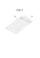
- FIG. 4 is a diagram illustrating an example of vibration of the panel 10 of the electronic device 1 according to the first embodiment.
- the display unit 20 is attached to the panel 10.
- the lower part of the panel 10 is less likely to vibrate than the upper part of the panel 10 to which the piezoelectric element 30 is attached. Therefore, sound leakage due to vibration of the lower portion of the panel 10 at the lower portion of the panel 10 can be reduced.
- the upper part of the panel 10 is directly bent by the piezoelectric element 30, and the vibration is attenuated at the lower part as compared with the upper part.
- the panel 10 is bent by the piezoelectric element 30 so that the portion directly above the piezoelectric element 30 protrudes higher than the surrounding area in the long side direction of the piezoelectric element 30.
- FIG. 5 is a flowchart showing an operation during a call by the electronic apparatus 1 according to the first embodiment.
- the control unit 50 when detecting an incoming voice call by the wireless communication unit 5, the control unit 50 detects a noise level (ambient sound level) collected by the microphone 7 (step S501).
- the noise level can be detected by, for example, sampling the output signal of the microphone 7 for a certain period of time and analyzing the sampling output within the audio frequency band to be transmitted.
- the control part 50 determines whether the detected noise level is more than a threshold value (step S502).
- the control unit 50 sets the side tone generated by driving the piezoelectric element 30 to the normal level (step S503). That is, the control unit 50 vibrates the piezoelectric element 30 with the amplification factor of the drive signal (side tone signal) of the piezoelectric element 30 based on the output signal of the microphone 7 as a normal (predetermined) amplification factor.
- control unit 50 turns off the side tone so that the piezoelectric element 30 is not driven by the output signal of the microphone 7 (step S504). Thereafter, the control unit 50 starts a call via the wireless communication unit 5.
- the noise level collected by the microphone 7 is detected before the start of a call, and when the noise level is less than the threshold, the side tone is set to the normal level.
- the side tone is turned off. Therefore, if the noise level is less than the threshold value, the user can listen to the surrounding sound including his / her transmitted sound as a side tone even if he / she talks with the panel 10 closed, thus reducing the sense of blockage. As well as being able to improve speech transmission.
- the noise level is equal to or higher than the threshold value, the side tone is turned off, so that the clarity of the received sound under noise can be increased.
- the panel 10 is sufficiently deformed from one end side in the longitudinal direction where the piezoelectric element 30 is bonded to the vicinity of the center due to the deformation of the piezoelectric element 30 attached to the back surface of the panel 10. Vibrate. Accordingly, the user brings a part of the user's body (for example, cartilage of the outer ear) into contact with at least a part of the upper region from the center of the panel 10, thereby causing air conduction sound and vibration due to vibration of the panel 10. I can hear the sound. Accordingly, air conduction sound and vibration sound can be transmitted to the user without causing the vibrating body to protrude from the outer surface of the housing 60, so that a very small vibrating body compared to the housing is brought into contact with the human body.
- a part of the user's body for example, cartilage of the outer ear
- the usability is improved as compared with the electronic device described in 1.
- the piezoelectric element 30 itself is not easily damaged.
- the case 60 is deformed instead of the panel 10
- the user tends to drop the terminal when generating vibration, whereas when the panel 10 is vibrated, Things are hard to happen.
- the display unit 20 and the piezoelectric element 30 are joined to the panel 10 by the joining member 70.
- the piezoelectric element 30 can be attached to the panel 10 in a state in which the degree of freedom of deformation of the piezoelectric element 30 is hardly hindered.
- the joining member 70 can be a non-heating type curable adhesive. Thereby, there is an advantage that thermal stress shrinkage hardly occurs between the piezoelectric element 30 and the panel 10 at the time of curing.
- the joining member 70 can be a double-sided tape. Thereby, there is an advantage that contraction stress is hardly applied between the piezoelectric element 30 and the panel 10 as in the case of using an adhesive.
- the panel 10 is also joined to the housing 60 by the joining member 70, the same effect can be obtained, and vibration from the panel 10 is not directly transmitted to the cover member 62 of the housing 60, and the housing 10 Compared with the case where the device itself vibrates greatly, the risk that the user drops the electronic device 1 can be reduced.
- the phase of the side tone is set to an opposite phase that attenuates ambient noise. Therefore, the control unit 50 performs side tone processing during a call by the wireless communication unit 5.
- FIG. 6 is a flowchart showing side tone processing during a call by the electronic apparatus according to the second embodiment.
- the output signal of the microphone 7 is divided for each frequency band (step S601).
- the frequency band to be divided can be set as appropriate.
- the audio frequency band to be transmitted can be divided into 0 Hz to 500 Hz, 500 Hz to 1000 Hz, 1000 Hz to 1500 Hz, and so on.
- the control unit 50 adjusts the phase of the output signal for each divided frequency band so that the output signal has an opposite phase that attenuates noise (step S602). Note that the phase adjustment may be performed so that the output signal in each frequency band is completely in reverse phase, or may be adjusted so that it is partially in reverse phase so that noise is weakened on average. .
- control unit 50 generates a side tone signal by synthesizing the output signals of the respective frequency bands adjusted in phase (step S603). Then, the control unit 50 drives the piezoelectric element 30 based on the generated side tone signal to generate an anti-phase side tone that weakens ambient noise (step S604).
- the electronic apparatus 1 divides the ambient noise collected by the microphone 7 into frequency bands and reverses the phase of the side tone so as to weaken the noise in each divided frequency band. Adjust to. Therefore, since ambient noise can be reduced in real time, the user can effectively reduce the sense of blockage when the user covers the ear with the panel 10 and makes the user listen to his / her transmitted sound as a side tone. Can improve the transmission ability.
- the user's transmitted sound is output as a side tone having an opposite phase, but the transmitted sound is not related to the surrounding noise, so there is no effect even if the phase changes.
- Other configurations and operational effects are the same as those of the first embodiment.
- the electronic device according to the third embodiment of the present invention has a side tone level according to the contact area of the user's ear (contact object) to the panel 10 in the configuration of the electronic device 1 according to the first embodiment. Adjust. Therefore, the control unit 50 has a function of detecting the contact area of the contact object with the panel 10, and is based on the contact area of the contact object with the panel 10 detected by the contact area detection function during a call by the wireless communication unit 5. To execute side tone interrupt processing.
- FIG. 7 is a flowchart showing an operation during a call by the electronic apparatus according to the third embodiment.
- the control unit 50 when detecting an incoming voice call by the wireless communication unit 5, the control unit 50 starts (starts) an interrupt timer (step S 701) and starts a call via the wireless communication unit 5 (step S 702). ).
- control unit 50 executes an interrupt process every time the set time by the interrupt timer started in step S701 elapses (step S703). Thereafter, when the control unit 50 ends the call (step S704), the control unit 50 ends the interrupt timer (step S705).
- FIG. 8 is a flowchart showing the interrupt processing executed in step S703 of FIG.
- the control unit 50 first detects the contact location of the panel 10 and calculates the contact area (step S801).
- the control unit 50 compares the calculated contact area S with the first threshold value S1 and the second threshold value S2 (S1 ⁇ S2) (step S802).
- the control unit 50 sets the level of the side tone generated by driving the piezoelectric element 30 to a normal (predetermined) level (step S803). That is, the control unit 50 sets the amplification factor of the drive signal (side tone signal) of the piezoelectric element 30 based on the output signal of the microphone 7 as a normal (predetermined) amplification factor.
- step S804 the control unit 50 turns off the side tone. That is, the control unit 50 performs control so as not to drive the piezoelectric element 30 based on the output signal of the microphone 7.
- step S805 the control unit 50 sets the side tone level higher than the normal level. That is, the control unit 50 increases the amplification factor of the drive signal (side tone signal) of the piezoelectric element 30 based on the output signal of the microphone 7 higher than normal (predetermined).
- the electronic device 1 detects the contact area of the user's ear to the panel 10 during a call, and adjusts the side tone level according to the contact area. That is, when the contact area of the panel 10 to the user's ear is in the normal range, it is assumed that ambient sound is likely to enter the user's ear as air conduction sound, and the probability that the user feels obstruction is low. The side tone level is set to the normal level. In addition, when the contact area is below the normal range, it is assumed that ambient sounds are more likely to enter the user's ears as air conduction sounds, and the probability that the user will feel a blockage is assumed to be lower. To do.
- the side tone level is set higher than the normal level.
- FIG. 9 is a diagram schematically illustrating a main part of the mounting structure of the electronic device 1 according to the fourth embodiment.
- 9 (a) is a front view
- FIG. 9 (b) is a cross-sectional view taken along the line bb in FIG. 9 (a)
- FIG. 9 (c) is taken along the line cc in FIG. 9 (a). It is sectional drawing.
- a cover panel (acrylic plate) that protects the display unit 20 as the panel 10 is arranged on the front surface of the upper casing 60a, and the input unit 40 is folded on the lower casing 60b.
- Mobile phone mobile phone.
- a reinforcing member 80 is disposed between the panel 10 and the piezoelectric element 30.
- the reinforcing member 80 is a resin plate including, for example, a resin plate, sheet metal, or glass fiber. That is, the electronic device 1 according to the fourth embodiment has a structure in which the piezoelectric element 30 and the reinforcing member 80 are bonded by the bonding member 70, and the reinforcing member 80 and the panel 10 are bonded by the bonding member 70.
- the display unit 20 is not bonded to the panel 10 but is supported by the housing 60a. That is, in the electronic device 1 according to the second embodiment, the display unit 20 is separated from the panel 10, and the display unit 20 and the support unit 90 that is a part of the housing 60 a are bonded by the bonding member 70. Structure.
- the support part 90 is not limited to the structure as a part of the housing
- the mouthpiece 42 is formed in the lower casing 60b.
- the microphone 7 is mounted on the circuit board 43 built in the housing 60b so as to face the mouthpiece 42 in the housing 60b. Therefore, the microphone 7 has directivity on the side facing the input unit 40.
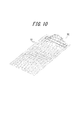
- FIG. 10 is a diagram illustrating an example of vibration of the panel 10 of the electronic device 1 according to the fourth embodiment.
- the panel 10 is an acrylic plate having a lower rigidity than the glass plate, and the display unit 20 is not bonded to the back surface of the panel 10.
- the amplitude generated by the piezoelectric element 30 is increased.
- the panel 10 vibrates not only in the attachment region to which the piezoelectric element 30 is attached, but also in a region away from the attachment region. For this reason, the user can hear the vibration sound by bringing his / her ear into contact with an arbitrary position of the panel 10 in addition to the air conduction sound through the air.
- one of the side tone processes described in the first to third embodiments is executed based on the ambient sound collected by the microphone 7.
- the reinforcing member 80 and the panel 10 are deformed due to the deformation of the piezoelectric element 30 attached to the panel 10 via the reinforcing member 80, and come into contact with the deformed panel 10. Air conduction sound and vibration sound are transmitted to the target object. Thereby, the air conduction sound and the vibration sound can be transmitted to the user without placing the vibration body itself on the ear.
- the piezoelectric element 30 is attached to the inner surface of the housing 60 a of the panel 10. For this reason, air conduction sound and vibration sound can be transmitted to the user without causing the vibrating body to protrude from the outer surface of the housing 60a.
- the panel 10 is deformed to transmit air conduction sound and vibration sound not only in the attachment region to which the piezoelectric element 30 is attached, but also in any part of the panel 10. For this reason, the user can hear the vibration sound by bringing his / her ear into contact with an arbitrary position of the panel 10 in addition to the air conduction sound through the air.
- the reinforcing member 80 between the piezoelectric element 30 and the panel 10, for example, when an external force is applied to the panel 10, the external force is transmitted to the piezoelectric element 30 and the piezoelectric element 30 may be damaged. Can be reduced. Moreover, even if the panel 10 is brought into strong contact with the human body, the vibration of the panel 10 can be hardly attenuated. Further, by disposing the reinforcing member 80 between the piezoelectric element 30 and the panel 10, the resonance frequency of the panel 10 is lowered, and the acoustic characteristics in the low frequency band are improved. Instead of the reinforcing member 80, a plate-like weight may be attached to the piezoelectric element 30 by the joining member 70.
- any one of the side tone processing described in the first to third embodiments is executed based on the ambient sound collected by the microphone 7.
- the panel 10 can reduce the feeling of obstruction when the user's ear is obstructed.
- the side tone is turned off in step S504.
- the level may be set lower than the level. That is, the amplification factor of the drive signal of the piezoelectric element 30 based on the output signal of the microphone 7 may be set to a predetermined amplification factor lower than the normal amplification factor. Further, the level setting process including ON / OFF of the side tone may be executed by an interrupt process during a call as in the case of the third embodiment.
- the side tone is turned off in step S804, but the side tone level is not turned off.
- the level may be set lower than the normal level.
- one microphone 7 is shared for collecting transmission sound and ambient sound.
- the microphone 7 is used as a main microphone for transmission, and ambient sound is collected at a position different from the microphone 7.
- a sub microphone may be arranged.
- the sub microphone may be arranged to have directivity on the side opposite to the microphone 7.
- the smartphone-type electronic device 1 shown in FIG. 3 as illustrated in a schematic cross-sectional view in FIG. 11, the side on which the piezoelectric element 30 is disposed is concentrated on the side opposite to the panel 10 of the housing 60.
- the sound microphone 44 is formed, and the sub microphone 8 can be mounted on the circuit board 130 so as to face the sound collection aperture 44.
- a sound collection port 44 is formed on the side opposite to the panel 10 of 60a, and the sub microphone 8 can be mounted on a circuit board (not shown) so as to face the sound collection port 44.
- the sub microphone 8 is not limited to the position illustrated in FIGS. 11 and 12, and can be disposed at an arbitrary position different from the main microphone 7.
- the side tone is output at the time of the call.
- the side tone may be output by selection by the user.
- the piezoelectric element 30 may be disposed at the center of the panel 10.
- the vibration of the piezoelectric element 30 is evenly transmitted to the entire panel 10 to improve the quality of the air conduction sound, and the user can listen to various positions of the panel 10. The vibration sound can be recognized even if it is touched.
- a plurality of piezoelectric elements 30 may be mounted.
- the piezoelectric element 30 is attached to the panel 10, but may be attached to a location different from the panel 10.
- the piezoelectric element 30 may be attached to a battery lid that is attached to the housing 60 and covers the battery. Since the battery lid is often attached to a surface different from the panel 10 in the electronic device 1 such as a mobile phone, according to such a configuration, the user can place a part of the body (for example, an ear) on the surface different from the panel 10. You can hear the sound by touching.
- the panel 10 can constitute a part or all of any of a display panel, an operation panel, a cover panel, and a lid panel for making the rechargeable battery removable.
- the panel 10 is a display panel
- the piezoelectric element 30 is disposed outside the display area for the display function.
- the operation panel includes a touch panel in the case of the smartphone-type electronic device 1 of FIG.
- the operation panel includes, for example, a sheet key which is a member constituting one surface of the operation unit side (lower side) housing, in which the key tops of the operation keys are integrally formed in the folding mobile phone of FIG.
- the bonding member for bonding the panel 10 and the piezoelectric element 30 and the bonding member for bonding the panel 10 and the housing 60 (60a) are described as the bonding member 70 having the same reference numeral.
- different joining members may be used as appropriate depending on the members to be joined.
- a contact area detection function of a contact object to the vibrating body there is a contact area detection function of a contact object to the vibrating body, and when the contact area detected by the contact area detection function exceeds a predetermined value, the ambient sound collected by the microphone Or vibrating the vibrating body based on ambient sound collected by the microphone when the contact area detected by the contact area detecting function is equal to or smaller than a predetermined value.
- a pressure detection mechanism is provided, and when this pressure detection value exceeds a predetermined value, the vibrating body is vibrated based on the ambient sound collected by the microphone.
- the vibration of the vibrating body based on the ambient sound collected by the microphone may be stopped. This is because when a large area is in contact with the vibrating body, it is often in contact with the vibrating body under a strong pressure. In addition, a sense of blockage due to the interruption of ambient sound is likely to occur when the pressure on the ear is strong.
- the pressure detection to a panel should just detect the electric current value and resistance value, for example, if it is a resistance film type touch panel, and also in the capacitance type touch panel, the change value of the capacitance may be detected. If detected, pressure can be easily detected.
- the vibration sound transmitted by the vibrating body may vibrate the middle ear or the inner ear via the soft tissue of the human body, for example, the cartilage of the ear.
Abstract
Provided is an electronic device (1) that presses a vibrating body (10) supported by a casing (60) against a human body so as to cause part of the human body to vibrate and allow the user to hear a vibration noise that is thereby communicated. The electronic device (1) is provided with a microphone (7), and the vibrating body (10) is made to vibrate on the basis of ambient sound collected by the microphone (7).
Description
本出願は、2012年5月14日に日本国に特許出願された特願2012-110961の優先権を主張するものであり、この先の出願の開示全体をここに参照のために取り込む。
This application claims the priority of Japanese Patent Application No. 2012-110961 filed in Japan on May 14, 2012, the entire disclosure of which is incorporated herein by reference.
本発明は、筐体に保持された振動体を人体に押し当てて人体の一部を振動させて伝える振動音を聞かせる電子機器に関する。
The present invention relates to an electronic device that hears a vibration sound transmitted by pressing a vibrating body held in a housing against a human body to vibrate a part of the human body.
特許文献1には、携帯電話などの電子機器として、気導音と骨導音とを利用者に伝えるものが記載されている。また、特許文献1には、気導音とは、物体の振動に起因する空気の振動が外耳道を通って鼓膜に伝わり、鼓膜が振動することによって利用者の聴覚神経に伝わる音であることが記載されている。また、特許文献1には、骨導音とは、振動する物体に接触する利用者の体の一部(例えば外耳の軟骨)を介して利用者の聴覚神経に伝わる音であることが記載されている。
Patent Document 1 describes an electronic device such as a mobile phone that conveys air conduction sound and bone conduction sound to a user. According to Patent Document 1, air conduction sound is sound transmitted to the auditory nerve of a user by vibration of air that is caused by vibration of an object being transmitted to the eardrum through the external auditory canal. Are listed. Patent Document 1 describes that bone conduction sound is sound transmitted to the user's auditory nerve through a part of the user's body (for example, cartilage of the outer ear) that contacts the vibrating object. ing.
特許文献1に記載された電話機では、圧電バイモルフ及び可撓性物質からなる短形板状の振動体が、筐体の外面に弾性部材を介して取り付けられる旨が記載されている。また、特許文献1には、この振動体の圧電バイモルフに電圧が印加されると、圧電材料が長手方向に伸縮することにより振動体が屈曲振動し、利用者が耳介に振動体を接触させると、気導音と骨導音とが利用者に伝えられることが記載されている。
In the telephone set described in Patent Document 1, it is described that a short plate-like vibrating body made of a piezoelectric bimorph and a flexible material is attached to the outer surface of a housing via an elastic member. Further, in Patent Document 1, when a voltage is applied to the piezoelectric bimorph of the vibrating body, the vibrating body bends and vibrates as the piezoelectric material expands and contracts in the longitudinal direction, and the user contacts the vibrating body with the auricle. It is described that air conduction sound and bone conduction sound are transmitted to the user.
特許文献1に記載の電子機器は、携帯電話などの筐体の外面に振動体が取り付けられ、振動体を振動させて音を聞かせる。そのため、利用者は、振動体を耳に確実に押し当てないと音が大きく聞こえない。また、その際、電子機器によって耳を塞ぐようにすれば、周囲音を遮蔽でき、騒音下での聴音の明瞭度を上げることができる。しかし、筐体によって耳が塞がれると、例えば電話の場合、利用者(送話者)の通話音が耳から抜け難くなって、利用者は閉塞感を感じることになる。
In the electronic device described in Patent Document 1, a vibrating body is attached to the outer surface of a housing such as a mobile phone, and the vibrating body is vibrated to make a sound. For this reason, the user cannot hear a loud sound unless the vibrating body is firmly pressed against the ear. At that time, if the ear is covered with an electronic device, ambient sounds can be blocked and the intelligibility of the listening sound under noise can be improved. However, when the ear is blocked by the housing, for example, in the case of a telephone, it becomes difficult for the user (speaker) to hear the sound of the conversation from the ear, and the user feels a blockage.
本発明の目的は、上述した課題を解決し、閉塞感を軽減できる電子機器を提供することにある。
An object of the present invention is to provide an electronic device that solves the above-described problems and can reduce the feeling of blockage.
本発明による電子機器は、筐体に保持された振動体を人体に押し当てて人体の一部を振動させて伝える振動音を聞かせる電子機器であって、
マイクを備え、該マイクで集音される周囲音に基づいて前記振動体を振動させる、ものである。 An electronic device according to the present invention is an electronic device that hears a vibration sound that is transmitted by vibrating a part of the human body by pressing the vibrating body held in the housing against the human body,
A microphone is provided, and the vibrating body is vibrated based on ambient sound collected by the microphone.
前記振動体は、3N~10Nの押圧力で押圧可能としてもよい。
The vibrator may be capable of being pressed with a pressing force of 3N to 10N.
前記マイクで集音される周囲音が所定値以下の場合、前記マイクで集音される周囲音に基づいて前記振動体を振動させてもよい。
When the ambient sound collected by the microphone is below a predetermined value, the vibrating body may be vibrated based on the ambient sound collected by the microphone.
前記マイクで集音される周囲音が所定値を超える場合、前記マイクで集音される周囲音に基づく前記振動体の振動を停止あるいは低減させてもよい。
When the ambient sound collected by the microphone exceeds a predetermined value, the vibration of the vibrating body based on the ambient sound collected by the microphone may be stopped or reduced.
前記振動体への接触物の接触面積検出機能あるいは圧力検出機能を有し、該接触面積検出機能により検出される接触面積あるいは、前記圧力検出機能により検出される圧力検出値が所定値を超える場合、前記マイクで集音される周囲音に基づいて前記振動体を振動させてもよい。
When the contact area detection function or pressure detection function of the contact object to the vibrating body is provided, and the contact area detected by the contact area detection function or the pressure detection value detected by the pressure detection function exceeds a predetermined value The vibrating body may be vibrated based on ambient sound collected by the microphone.
前記接触面積検出機能により検出される接触面積あるいは圧力検出機能により検出される圧力検出値が所定値以下の場合、前記マイクで集音される周囲音に基づく前記振動体の振動を停止させるあるいは低減させてもよい。
When the contact area detected by the contact area detection function or the pressure detection value detected by the pressure detection function is a predetermined value or less, the vibration of the vibrating body based on the ambient sound collected by the microphone is stopped or reduced. You may let them.
前記マイクで集音される周囲音に基づいて、前記振動体を前記周囲音とは逆位相で振動させてもよい。
The vibrating body may be vibrated in a phase opposite to that of the ambient sound based on the ambient sound collected by the microphone.
前記振動体を、前記周囲音の周波数帯域毎に、前記周囲音とは逆位相となるように位相調整して振動させてもよい。
The vibrating body may be vibrated by adjusting the phase so as to have an opposite phase to the ambient sound for each frequency band of the ambient sound.
通話機能を有し、該通話機能による通話中に、前記マイクで集音される周囲音に基づいて前記振動体を振動させてもよい。
It may have a call function, and the vibrator may be vibrated based on ambient sound collected by the microphone during a call using the call function.
周囲音が集音される前記マイクは、送話用のメインマイクとは異なる位置に配置されたサブマイクであってもよい。
The microphone for collecting ambient sounds may be a sub microphone arranged at a position different from the main microphone for transmission.
前記メインマイクは、前記筐体の前記振動体が面する側に指向性を有するように配置され、前記サブマイクは、前記メインマイクとは反対側に指向性を有するように配置されてもよい。
The main microphone may be arranged so as to have directivity on the side of the casing facing the vibrating body, and the sub microphone may be arranged so as to have directivity on the side opposite to the main microphone.
前記振動体は、圧電素子と、該圧電素子を支持するパネルとを備え、前記パネルが前記筐体に保持されてもよい。
The vibrator may include a piezoelectric element and a panel that supports the piezoelectric element, and the panel may be held by the casing.
前記圧電素子は、前記筺体の一方向における一端側に配置されてもよい。
The piezoelectric element may be disposed on one end side in one direction of the casing.
前記パネルは、平面視における形状が矩形状を成し、対向する一方の2辺の長さが、対耳珠から対耳輪下脚までの長さ以上であってもよい。
The panel may have a rectangular shape in plan view, and the length of one of the two opposing sides may be equal to or longer than the length from the antitragus to the lower leg of the antiaural ring.
前記パネルは、対向する他方の2辺の長さが、耳珠から対耳輪までの長さ以上であってもよい。
The length of the other two sides of the panel may be equal to or greater than the length from the tragus to the earring.
前記圧電素子は、前記筐体に接合部材により接合されて固定されてもよい。
The piezoelectric element may be bonded and fixed to the casing by a bonding member.
前記接合部材は、非加熱型硬化性の接着材であってもよい。
The joining member may be a non-heating type curable adhesive.
前記接合部材は、両面テープであってもよい。
The bonding member may be a double-sided tape.
前記パネルは、前記筐体に接合部材により接合されてもよい。
The panel may be joined to the casing by a joining member.
前記パネルを前記筐体に接合する前記接合部材は、非加熱型硬化性の接着材であってもよい。
The joining member for joining the panel to the housing may be a non-heating type curable adhesive.
前記パネルを前記筐体に接合する前記接合部材は、両面テープであってもよい。
The bonding member for bonding the panel to the housing may be a double-sided tape.
前記パネルは、表示部、入力部、前記表示部のカバーのうちいずれかの一部または全部を構成してもよい。
The panel may constitute part or all of the display unit, the input unit, and the cover of the display unit.
前記パネルにおける前記圧電素子の固定部分は、当該パネルの平面視における前記表示部との重複領域の外部に位置してもよい。
The fixed portion of the piezoelectric element in the panel may be located outside the overlapping area with the display unit in plan view of the panel.
前記表示部は、前記筺体の内側から前記パネルに固定されてもよい。
The display unit may be fixed to the panel from the inside of the housing.
前記振動体は、前記振動音に加えて気導音を聞かせてもよい。
The vibrating body may hear an air conduction sound in addition to the vibration sound.
本発明に係る電子機器によれば、閉塞感を軽減することが可能となる。
The electronic device according to the present invention can reduce the feeling of blockage.
以降、諸図面を参照しながら、本発明の実施態様を詳細に説明する。
Hereinafter, embodiments of the present invention will be described in detail with reference to the drawings.
(第1の実施形態)
図1は、本発明の第1の実施形態に係る電子機器1の要部の機能ブロックを示す図である。電子機器1は、例えば通話機能を有する携帯電話であって、無線通信部5と、マイク7と、パネル10と、表示部20と、圧電素子30と、入力部40と、制御部50と、を備える。無線通信部5は、公知の構成からなり、基地局等を介して通信ネットワークに無線接続される。マイク7は、コンデンサマイク等の公知のマイクからなり、無線通信部5を介しての通話時に利用者が発する送話音等を集音する。 (First embodiment)
FIG. 1 is a diagram illustrating functional blocks of a main part of theelectronic device 1 according to the first embodiment of the present invention. The electronic device 1 is, for example, a mobile phone having a call function, and includes a wireless communication unit 5, a microphone 7, a panel 10, a display unit 20, a piezoelectric element 30, an input unit 40, a control unit 50, Is provided. The wireless communication unit 5 has a known configuration and is wirelessly connected to a communication network via a base station or the like. The microphone 7 is a known microphone such as a condenser microphone, and collects a transmission sound or the like emitted by the user during a call through the wireless communication unit 5.
図1は、本発明の第1の実施形態に係る電子機器1の要部の機能ブロックを示す図である。電子機器1は、例えば通話機能を有する携帯電話であって、無線通信部5と、マイク7と、パネル10と、表示部20と、圧電素子30と、入力部40と、制御部50と、を備える。無線通信部5は、公知の構成からなり、基地局等を介して通信ネットワークに無線接続される。マイク7は、コンデンサマイク等の公知のマイクからなり、無線通信部5を介しての通話時に利用者が発する送話音等を集音する。 (First embodiment)
FIG. 1 is a diagram illustrating functional blocks of a main part of the
パネル10は、接触を検出するタッチパネル、または表示部20を保護するカバーパネル等である。パネル10は、例えばガラス、またはアクリル等の合成樹脂により形成される。パネル10の形状は板状であるとよい。パネル10は、平板であってもよいし、表面が滑らかに傾斜する曲面パネルであってもよい。パネル10は、タッチパネルである場合、利用者の指、ペン、又はスタイラスペン等の接触を検出する。タッチパネルの検出方式は、静電容量方式、抵抗膜方式、表面弾性波方式(又は超音波方式)、赤外線方式、電磁誘導方式、及び荷重検出方式等の任意の方式を用いることができる。
The panel 10 is a touch panel that detects contact, a cover panel that protects the display unit 20, or the like. The panel 10 is made of, for example, glass or a synthetic resin such as acrylic. The shape of the panel 10 may be a plate shape. The panel 10 may be a flat plate or a curved panel whose surface is smoothly inclined. When the panel 10 is a touch panel, the touch of a user's finger, pen, stylus pen, or the like is detected. As a detection method of the touch panel, any method such as a capacitance method, a resistance film method, a surface acoustic wave method (or an ultrasonic method), an infrared method, an electromagnetic induction method, and a load detection method can be used.
表示部20は、液晶ディスプレイ、有機ELディスプレイ、又は無機ELディスプレイ等の表示デバイスである。表示部20は、パネル10の背面側に設けられる。例えば、表示部20は、接合部材(例えば接着剤)によりパネル10の背面に配設される。あるいは、表示部20は、パネル10と離間して、電子機器1の筐体に支持される。
The display unit 20 is a display device such as a liquid crystal display, an organic EL display, or an inorganic EL display. The display unit 20 is provided on the back side of the panel 10. For example, the display unit 20 is disposed on the back surface of the panel 10 by a joining member (for example, an adhesive). Alternatively, the display unit 20 is separated from the panel 10 and supported by the housing of the electronic device 1.
圧電素子30は、電気信号(電圧)を印加することで、構成材料の電気機械結合係数に従い伸縮または湾曲(屈曲)する素子である。これらの素子は、例えばセラミック製や水晶からなるものが用いられる。圧電素子30は、ユニモルフ、バイモルフまたは積層型圧電素子であってよい。積層型圧電素子には、ユニモルフを積層した(例えば16層または24層積層した)積層型ユニモルフ素子、またはバイモルフを積層した(例えば16層または24層積層した)積層型バイモルフ素子が含まれる。積層型の圧電素子は、例えばPZT(チタン酸ジルコン酸鉛)からなる複数の誘電体層と、該複数の誘電体層間に配置された電極層との積層構造体から構成される。ユニモルフは、電気信号(電圧)が印加されると伸縮し、バイモルフは、電気信号(電圧)が印加されると湾曲する。
The piezoelectric element 30 is an element that expands and contracts or bends (bends) according to the electromechanical coupling coefficient of the constituent material by applying an electric signal (voltage). For these elements, for example, those made of ceramic or quartz are used. The piezoelectric element 30 may be a unimorph, bimorph, or multilayer piezoelectric element. The stacked piezoelectric element includes a stacked unimorph element in which unimorphs are stacked (for example, 16 layers or 24 layers), or a stacked bimorph element in which bimorphs are stacked (for example, 16 layers or 24 layers are stacked). The laminated piezoelectric element is composed of a laminated structure of a plurality of dielectric layers made of, for example, PZT (lead zirconate titanate) and electrode layers arranged between the plurality of dielectric layers. Unimorphs expand and contract when an electrical signal (voltage) is applied, and bimorphs bend when an electrical signal (voltage) is applied.
圧電素子30は、パネル10の背面(電子機器1の内部側の面)に配置される。圧電素子30は、接合部材(例えば両面テープ)によりパネル10に取り付けられる。圧電素子30は、中間部材(例えば板金)を介してパネル10に取り付けられてもよい。圧電素子30は、パネル10の背面に配置された状態で、筐体の内部側の表面と所定の距離だけ離間している。圧電素子30は、伸縮または湾曲した状態でも、筐体の内部側の表面と所定の距離だけ離間しているとよい。すなわち、圧電素子30と筐体の内部側の面との間の距離は、圧電素子30の最大変形量よりも大きいとよい。
The piezoelectric element 30 is disposed on the back surface of the panel 10 (the surface on the inner side of the electronic device 1). The piezoelectric element 30 is attached to the panel 10 by a joining member (for example, double-sided tape). The piezoelectric element 30 may be attached to the panel 10 via an intermediate member (for example, a sheet metal). The piezoelectric element 30 is disposed on the back surface of the panel 10 and is separated from the surface on the inner side of the housing by a predetermined distance. The piezoelectric element 30 may be separated from the surface on the inner side of the housing by a predetermined distance even in a stretched or curved state. That is, the distance between the piezoelectric element 30 and the inner surface of the housing is preferably larger than the maximum deformation amount of the piezoelectric element 30.
入力部40は、利用者からの操作入力を受け付けるものであり、例えば、操作ボタン(操作キー)から構成される。なお、パネル10がタッチパネルである場合には、パネル10も利用者からの接触を検出することにより、利用者からの操作入力を受け付けることができる。
The input unit 40 receives an operation input from the user, and includes, for example, an operation button (operation key). In addition, when the panel 10 is a touch panel, the panel 10 can also accept the operation input from a user by detecting the contact from a user.
制御部50は、電子機器1を制御するプロセッサである。制御部50は、通話時において、マイク7により集音されて電気音響変換された音声信号を処理して無線通信部5から送信する。また、制御部50は、圧電素子30に所定の電気信号(通話相手の音声、サイドトーン、着信メロディ、音楽を含む楽曲等の音響信号に応じた電圧)を印加する。なお、音声信号は、内部メモリに記憶された音楽データに基づくものでもよいし、外部サーバ等に記憶されている音楽データがネットワークを介して再生されるものであってもよい。
The control unit 50 is a processor that controls the electronic device 1. The control unit 50 processes the audio signal collected by the microphone 7 and subjected to electroacoustic conversion during a call, and transmits the processed signal from the wireless communication unit 5. In addition, the control unit 50 applies a predetermined electrical signal (voltage corresponding to a sound signal of a call partner's voice, side tone, incoming melody, music, etc.) to the piezoelectric element 30. The audio signal may be based on music data stored in an internal memory, or music data stored in an external server or the like may be reproduced via a network.
圧電素子30に電気信号が印加されると、圧電素子30は長手方向に伸縮又は湾曲する。このとき、圧電素子30が取り付けられたパネル10は、圧電素子30の伸縮又は湾曲にあわせて変形し、パネル10が湾曲振動する。ここで、制御部50が圧電素子30に印加する電気信号の最大電圧は、例えば、振動音ではなく気導音による音の伝導を目的とした所謂パネルスピーカの印加電圧である±5Vよりも高い、±15Vであってよい。これにより、利用者が例えば3N以上の力(5N~10Nの力)で自身の体にパネル10を押し付けた場合であっても、パネル10に十分な湾曲振動を発生させ、利用者の体の一部(例えば外耳の軟骨)を介する振動音を発生させることができる。尚、どの程度の印加電圧を用いるかは、パネル10の筐体または支持部材に対する固定強度もしくは圧電素子30の性能に応じて適宜調整可能である。
When an electrical signal is applied to the piezoelectric element 30, the piezoelectric element 30 expands or contracts in the longitudinal direction. At this time, the panel 10 to which the piezoelectric element 30 is attached is deformed in accordance with the expansion or contraction or bending of the piezoelectric element 30, and the panel 10 vibrates. Here, the maximum voltage of the electric signal applied to the piezoelectric element 30 by the control unit 50 is higher than ± 5 V, which is an applied voltage of a so-called panel speaker for the purpose of conducting sound by air conduction sound instead of vibration sound, for example. , ± 15V. Thus, even when the user presses the panel 10 against his / her body with a force of 3N or more (5N to 10N force), for example, the panel 10 generates sufficient bending vibration, and the user's body Vibration sound can be generated through a part (eg, cartilage of the outer ear). Note that how much applied voltage is used can be appropriately adjusted according to the fixing strength of the panel 10 to the casing or the support member or the performance of the piezoelectric element 30.
制御部50が圧電素子30に電気信号を印加すると、圧電素子30は長手方向に伸縮または屈曲する。このとき、圧電素子30が取り付けられたパネル10は、圧電素子30の伸縮または屈曲にあわせて変形し、パネル10が振動する。パネル10は、圧電素子30の伸縮または屈曲によって湾曲する。パネル10は、圧電素子30によって直接的に曲げられる。「パネル10が圧電素子によって直接的に曲げられる」とは、従来のパネルスピーカで採用されているような、圧電素子をケーシング内に配設して構成される圧電アクチュエータの慣性力によりパネルの特定の領域が加振されてパネルが変形する現象とは異なる。「パネル10が圧電素子によって直接的に曲げられる」とは、圧電素子の伸縮または屈曲(湾曲)が、接合部材を介して或いは接合部材及び後述の補強部材80を介して、直にパネルを曲げることを意味する。
When the control unit 50 applies an electrical signal to the piezoelectric element 30, the piezoelectric element 30 expands or contracts in the longitudinal direction. At this time, the panel 10 to which the piezoelectric element 30 is attached is deformed in accordance with expansion / contraction or bending of the piezoelectric element 30, and the panel 10 vibrates. The panel 10 is bent by expansion / contraction or bending of the piezoelectric element 30. The panel 10 is bent directly by the piezoelectric element 30. “The panel 10 is directly bent by the piezoelectric element” means that the panel is specified by the inertial force of the piezoelectric actuator configured by arranging the piezoelectric element in the casing as used in a conventional panel speaker. This is different from the phenomenon in which the panel is deformed by exciting the region. “The panel 10 is directly bent by the piezoelectric element” means that expansion or contraction (bending) of the piezoelectric element bends the panel directly via the bonding member or via the bonding member and the reinforcing member 80 described later. Means that.
このため、パネル10は、気導音を発生させるとともに、利用者が体の一部(例えば外耳の軟骨)を接触させた場合、体の一部を介する人体振動音を発生させる。例えば、制御部50は、例えば通話相手の音声に係る音声信号に応じた電気信号を圧電素子30に印加させ、その音声信号に対応する気導音及び人体振動音を発生させることができる。
For this reason, the panel 10 generates air conduction sound and, when the user contacts a part of the body (for example, cartilage of the outer ear), generates a human body vibration sound through the part of the body. For example, the control unit 50 can generate an air conduction sound and a human body vibration sound corresponding to the voice signal by applying an electrical signal corresponding to the voice signal related to the voice of the other party to the piezoelectric element 30, for example.
パネル10は、圧電素子30が取り付けられた取付領域だけでなく、取付領域から離れた領域も湾曲振動する。パネル10は、振動する領域において、当該パネル10の主面と交差する方向に振動する箇所を複数有し、当該複数の箇所の各々において、振動の振幅の値が、時間とともにプラスからマイナスに、あるいはその逆に変化する。パネル10は、ある瞬間において、振動の振幅が相対的に大きい部分と振動の振幅が相対的に小さい部分とが一見パネル10の略全体にランダムにあるいは周期的に分布した振動をする。即ちパネル10全域にわたって、複数の波の振動が検出される。利用者が例えば5N~10Nの力で自身の体にパネル10を押し付けた場合であっても、パネル10の上述したような振動が減衰しないためには、制御部50が圧電素子30に対して印加する最大電圧は、±15Vであってよい。そのため、利用者は、上述した圧電素子30の取付領域から離れた領域、例えばパネル10の中央部に耳を接触させて音を聞くことができる。
The panel 10 bends and vibrates not only in the attachment region where the piezoelectric element 30 is attached, but also in the region away from the attachment region. The panel 10 has a plurality of locations that vibrate in a direction intersecting the main surface of the panel 10 in the vibrating region, and the amplitude value of the vibration is increased from positive to negative with time in each of the plurality of locations. Or vice versa. At a certain moment, the panel 10 vibrates in such a manner that a portion having a relatively large vibration amplitude and a portion having a relatively small vibration amplitude are distributed randomly or periodically throughout the panel 10 at first glance. That is, vibrations of a plurality of waves are detected over the entire panel 10. Even when the user presses the panel 10 against his / her body with a force of 5 N to 10 N, for example, the control unit 50 does not attenuate the piezoelectric element 30 in order to prevent the above-described vibration of the panel 10 from being attenuated. The maximum voltage to be applied may be ± 15V. Therefore, the user can hear the sound by bringing his / her ear into contact with a region away from the above-described region where the piezoelectric element 30 is attached, for example, the center of the panel 10.
ここで、パネル10は、利用者の耳とほぼ同じ大きさであってよい。また、パネル10は、図2に示すように、利用者の耳よりも大きいものであってもよい。この場合、利用者が音を聞く際、電子機器1のパネル10により耳全体が覆われやすいことから、周囲音(ノイズ)を外耳道に入りにくくできる。パネル10は、対耳輪下脚(下対輪脚)から対耳珠までの間の距離に相当する長さと、耳珠から対耳輪までの間の距離に相当する幅とを有する領域よりも広い領域が振動すればよい。パネル10は、好ましくは、耳輪における対耳輪上脚(上対輪脚)近傍の部位から耳垂までの間の距離に相当する長さと、耳珠から耳輪における対耳輪近傍の部位までの間の距離に相当する幅を有する領域が振動すればよい。上記の長さおよび幅を有する領域は、長方形状の領域であってもよいし、上記の長さを長径、上記の幅を短径とする楕円形状であってもよい。日本人の耳の平均的な大きさは、社団法人 人間生活工学研究センター(HQL)作成の日本人の人体寸法データベース(1992-1994)等を参照すれば知ることができる。尚、パネル10が日本人の耳の平均的な大きさ以上の大きさであれば、パネル10は概ね外国人の耳全体を覆うことができる大きさであると考えられる。上記のような寸法や形状を有することで、パネル10は、ユーザの耳を覆うことができ、耳に当てたときの位置ずれに対して寛容になる。
Here, the panel 10 may be approximately the same size as the user's ear. The panel 10 may be larger than the user's ear, as shown in FIG. In this case, when the user listens to the sound, the entire ear is easily covered with the panel 10 of the electronic device 1, so that it is difficult for ambient sounds (noise) to enter the ear canal. Panel 10 is an area wider than an area having a length corresponding to the distance from the lower leg of the anti-annulus (lower anti-limb) to the anti-tragus and a width corresponding to the distance from the tragus to the anti-annulus. Should just vibrate. The panel 10 preferably has a length corresponding to the distance between a portion near the upper leg of the ankle ring (upper pair leg) in the ear ring and the earlobe, and a distance between the tragus and a portion near the ear ring in the ear ring. It suffices that a region having a width corresponding to is vibrated. The region having the above length and width may be a rectangular region, or may be an elliptical shape having the above length as the major axis and the above width as the minor axis. The average size of Japanese ears can be found by referring to the Japanese human body size database (1992-1994) created by the Human Life Engineering Research Center (HQL). If the panel 10 is larger than the average size of Japanese ears, the panel 10 is considered to be large enough to cover the entire foreign ear. By having the dimensions and shapes as described above, the panel 10 can cover the user's ears and is tolerant of misalignment when applied to the ears.
上記の電子機器1は、パネル10の振動により、気導音と、利用者の体の一部(例えば外耳の軟骨)を介する振動音とを利用者に伝えることができる。そのため、従来のダイナミックレシーバと同等の音量の音を出力する場合、パネル10が振動することで空気の振動により電子機器1の周囲へ伝わる音は、ダイナミックレシーバと比較して少ない。したがって、例えば録音されたメッセージを電車内等で聞く場合等に適している。
The electronic device 1 can transmit the air conduction sound and the vibration sound through a part of the user's body (for example, cartilage of the outer ear) to the user by the vibration of the panel 10. Therefore, when outputting a sound having a volume equivalent to that of a conventional dynamic receiver, the sound transmitted to the periphery of the electronic device 1 due to the vibration of the air due to the vibration of the panel 10 is less than that of the dynamic receiver. Therefore, it is suitable, for example, when listening to a recorded message on a train or the like.
また、上記の電子機器1は、パネル10の振動によって振動音を伝えるため、例えば利用者がイヤホンまたはヘッドホンを身につけていても、それらに電子機器1を接触させることで、利用者はイヤホンまたはヘッドホンおよび体の一部を介して音を聞くことができる。
In addition, since the electronic device 1 transmits vibration sound due to the vibration of the panel 10, even if the user wears an earphone or a headphone, for example, the user can touch the electronic device 1 to contact the earphone or the headphone. Sounds can be heard through headphones and body parts.
上記の電子機器1は、パネル10の振動により利用者に音を伝える。そのため、電子機器1が別途ダイナミックレシーバを備えない場合、音声伝達のための開口部(放音口)を筐体に形成する必要がなく、電子機器1の防水構造が簡略化できる。尚、電子機器1がダイナミックレシーバを備える場合、放音口は、気体は通すが液体は通さない部材によって閉塞されるとよい。気体は通すが液体は通さない部材は、例えばゴアテックス(登録商標)である。
The electronic device 1 transmits sound to the user by the vibration of the panel 10. Therefore, when the electronic device 1 does not include a separate dynamic receiver, it is not necessary to form an opening (sound outlet) for sound transmission in the housing, and the waterproof structure of the electronic device 1 can be simplified. In addition, when the electronic device 1 is provided with a dynamic receiver, the sound emission port is preferably closed by a member that allows gas to pass but not liquid. An example of the member that allows gas to pass but not liquid is Gore-Tex (registered trademark).
図3は、第1の実施形態に係る電子機器1の実装構造の要部を概略的に示す図である。図3(a)は正面図、図3(b)は図3(a)におけるb-b線に沿った断面図である。図3に示す電子機器1は、パネル10として長方形状のガラス板が筐体60(例えば金属や樹脂のケース)の前面に配されたスマートフォンである。
FIG. 3 is a diagram schematically illustrating a main part of the mounting structure of the electronic device 1 according to the first embodiment. 3A is a front view, and FIG. 3B is a cross-sectional view taken along line bb in FIG. 3A. The electronic device 1 illustrated in FIG. 3 is a smartphone in which a rectangular glass plate is disposed as a panel 10 on the front surface of a housing 60 (for example, a metal or resin case).
パネル10は、例えば静電容量方式のタッチパネルを構成するもので、接合部材70を介して筐体60に支持されて、3N~10Nの押圧力で押圧可能に構成されている。パネル10には、長手方向の一端側(上部)を除く背面に、接合部材70を介して表示部20が接合されている。表示部20は、回路基板130に接続されている。また、パネル10の一方向における一端側である上部背面には、パネル10とともに振動体を構成する圧電素子30が接合部材70を介して接合されている。圧電素子30は、長方形状を成し、その長辺がパネル10の短辺に沿うように接合される。なお、接合部材70は、熱硬化性あるいは紫外線硬化性等を有する接着剤や両面テープ等であり、例えば無色透明のアクリル系紫外線硬化型接着剤である光学弾性樹脂でもよい。
The panel 10 constitutes, for example, a capacitive touch panel, and is supported by the housing 60 via a joining member 70 and is configured to be pressed with a pressing force of 3N to 10N. The display unit 20 is bonded to the panel 10 via a bonding member 70 on the back surface except for one end side (upper part) in the longitudinal direction. The display unit 20 is connected to the circuit board 130. In addition, a piezoelectric element 30 that constitutes a vibrating body together with the panel 10 is bonded to the upper back surface, which is one end side in one direction of the panel 10, via a bonding member 70. The piezoelectric element 30 has a rectangular shape and is bonded so that its long side is along the short side of the panel 10. The bonding member 70 is an adhesive having a thermosetting property or an ultraviolet curable property, a double-sided tape, or the like, and may be, for example, an optical elastic resin that is a colorless and transparent acrylic ultraviolet curable adhesive.
入力部40は、パネル10の長手方向の他端部(下部)側において筐体60に支持されている。また、入力部40には、破線で示すように、マイクの送話口41が形成されている。つまり、長方形状の筐体60の上部側に圧電素子30が配置され、下部側に送話口41が形成されている。マイク7は、送話口41と対向するように、回路基板130に搭載されている。したがって、マイク7は、パネル10が面する側に指向性を有している。
The input unit 40 is supported by the housing 60 on the other end (lower) side in the longitudinal direction of the panel 10. In addition, a microphone mouthpiece 41 is formed in the input unit 40 as indicated by a broken line. That is, the piezoelectric element 30 is arranged on the upper side of the rectangular casing 60, and the mouthpiece 41 is formed on the lower side. The microphone 7 is mounted on the circuit board 130 so as to face the mouthpiece 41. Accordingly, the microphone 7 has directivity on the side facing the panel 10.
図4は、第1の実施形態に係る電子機器1のパネル10の振動の一例を示す図である。第1の実施形態に係る電子機器1では、表示部20がパネル10に取り付けられている。このため、パネル10の下部は、圧電素子30が取り付けられたパネル10の上部に比して振動しにくくなる。そのため、パネル10の下部において、パネル10の下部が振動することによる音漏れが低減できる。パネル10は、圧電素子30によってその上部が直接的に曲げられ、当該上部に比して下部では振動が減衰する。パネル10は、圧電素子30の長辺方向において該圧電素子30の直上がその周囲と比較して最も高く隆起するように、圧電素子30によって曲げられる。
FIG. 4 is a diagram illustrating an example of vibration of the panel 10 of the electronic device 1 according to the first embodiment. In the electronic device 1 according to the first embodiment, the display unit 20 is attached to the panel 10. For this reason, the lower part of the panel 10 is less likely to vibrate than the upper part of the panel 10 to which the piezoelectric element 30 is attached. Therefore, sound leakage due to vibration of the lower portion of the panel 10 at the lower portion of the panel 10 can be reduced. The upper part of the panel 10 is directly bent by the piezoelectric element 30, and the vibration is attenuated at the lower part as compared with the upper part. The panel 10 is bent by the piezoelectric element 30 so that the portion directly above the piezoelectric element 30 protrudes higher than the surrounding area in the long side direction of the piezoelectric element 30.
図5は、第1の実施の形態に係る電子機器1による通話時の動作を示すフローチャートである。本実施形態において、制御部50は、無線通信部5による音声着信を検出すると、マイク7で集音される騒音レベル(周囲音レベル)を検出する(ステップS501)。騒音レベルは、例えば、マイク7の出力信号を一定時間サンプリングし、そのサンプリング出力を、伝送する音声周波数帯域内で周波数解析して検出することができる。そして、制御部50は、検出した騒音レベルが閾値以上か否かを判定する(ステップS502)。
FIG. 5 is a flowchart showing an operation during a call by the electronic apparatus 1 according to the first embodiment. In the present embodiment, when detecting an incoming voice call by the wireless communication unit 5, the control unit 50 detects a noise level (ambient sound level) collected by the microphone 7 (step S501). The noise level can be detected by, for example, sampling the output signal of the microphone 7 for a certain period of time and analyzing the sampling output within the audio frequency band to be transmitted. And the control part 50 determines whether the detected noise level is more than a threshold value (step S502).
その結果、騒音レベルが閾値未満(No)の場合、制御部50は、圧電素子30を駆動して発生させるサイドトーンを通常レベルに設定する(ステップS503)。つまり、制御部50は、マイク7の出力信号に基づく圧電素子30の駆動信号(サイドトーン信号)の増幅率を通常(所定)の増幅率として、圧電素子30を振動させる。
As a result, when the noise level is less than the threshold (No), the control unit 50 sets the side tone generated by driving the piezoelectric element 30 to the normal level (step S503). That is, the control unit 50 vibrates the piezoelectric element 30 with the amplification factor of the drive signal (side tone signal) of the piezoelectric element 30 based on the output signal of the microphone 7 as a normal (predetermined) amplification factor.
これに対し、騒音レベルが閾値以上(Yes)の場合、制御部50は、サイドトーンをOFFにして、マイク7の出力信号によって圧電素子30を駆動しないようにする(ステップS504)。その後、制御部50は、無線通信部5を介しての通話を開始させる。
On the other hand, when the noise level is equal to or higher than the threshold (Yes), the control unit 50 turns off the side tone so that the piezoelectric element 30 is not driven by the output signal of the microphone 7 (step S504). Thereafter, the control unit 50 starts a call via the wireless communication unit 5.
このように、本実施形態に係る電子機器1によれば、通話開始前にマイク7で集音される騒音レベルを検出し、騒音レベルが閾値未満の場合は、サイドトーンを通常レベルに設定し、騒音レベルが閾値以上の場合は、サイドトーンをOFFにしている。したがって、騒音レベルが閾値未満であれば、利用者は、パネル10により耳を塞いで通話しても、自身の送話音を含む周囲音をサイドトーンとして聴くことができるので、閉塞感を軽減できるとともに、送話性を向上することができる。また、騒音レベルが閾値以上の場合は、サイドトーンがOFFとなるので、騒音下での受話音の明瞭度を上げることができる。
As described above, according to the electronic device 1 according to the present embodiment, the noise level collected by the microphone 7 is detected before the start of a call, and when the noise level is less than the threshold, the side tone is set to the normal level. When the noise level is equal to or higher than the threshold, the side tone is turned off. Therefore, if the noise level is less than the threshold value, the user can listen to the surrounding sound including his / her transmitted sound as a side tone even if he / she talks with the panel 10 closed, thus reducing the sense of blockage. As well as being able to improve speech transmission. When the noise level is equal to or higher than the threshold value, the side tone is turned off, so that the clarity of the received sound under noise can be increased.
また、パネル10は、該パネル10の背面に取り付けられた圧電素子30の変形に起因してパネル10が変形して、圧電素子30が接着された長手方向の一端側から中央部近傍まで十分に振動する。したがって、利用者は、パネル10の中央部から上部の領域の少なくとも一部に、利用者の体の一部(例えば外耳の軟骨)を接触させることにより、パネル10の振動による気導音及び振動音を聞くことができる。これにより、振動体を筐体60の外面に突出させることなく気導音と振動音とを利用者に伝えることができるため、筐体に比べて非常に小さな振動体を人体に接触させる特許文献1に記載の電子機器よりも使い勝手が向上する。また、圧電素子自体に利用者の耳を当てる必要がないので圧電素子30そのものが破損しにくい。また、パネル10ではなく筐体60を変形させる場合には、振動を発生させる際に、利用者が端末を落としてしまいやすいのに対して、パネル10を振動させた場合には、このようなことが起きにくい。
In addition, the panel 10 is sufficiently deformed from one end side in the longitudinal direction where the piezoelectric element 30 is bonded to the vicinity of the center due to the deformation of the piezoelectric element 30 attached to the back surface of the panel 10. Vibrate. Accordingly, the user brings a part of the user's body (for example, cartilage of the outer ear) into contact with at least a part of the upper region from the center of the panel 10, thereby causing air conduction sound and vibration due to vibration of the panel 10. I can hear the sound. Accordingly, air conduction sound and vibration sound can be transmitted to the user without causing the vibrating body to protrude from the outer surface of the housing 60, so that a very small vibrating body compared to the housing is brought into contact with the human body. The usability is improved as compared with the electronic device described in 1. In addition, since it is not necessary to put the user's ears on the piezoelectric element itself, the piezoelectric element 30 itself is not easily damaged. Further, when the case 60 is deformed instead of the panel 10, the user tends to drop the terminal when generating vibration, whereas when the panel 10 is vibrated, Things are hard to happen.
また、本実施形態において、表示部20及び圧電素子30は、パネル10に接合部材70により接合されている。これにより、圧電素子30の変形の自由度を阻害しにくい状態で圧電素子30をパネル10に取り付けることができる。また、接合部材70は、非加熱型硬化性の接着剤とすることができる。これにより、硬化時に、圧電素子30とパネル10との間に熱応力収縮が発生しにくいという利点がある。また、接合部材70は、両面テープとすることができる。これにより、圧電素子30とパネル10との間に接着剤使用時のような収縮応力がかかりにくいという利点がある。また、パネル10も、接合部材70により筐体60に接合されているので、同様の効果が得られる他、筐体60のカバー部材62にパネル10からの振動がダイレクトに伝わりにくくなり、筐体自体が大きく振動する場合と比較して、ユーザが電子機器1を落としてしまう恐れを低減できる。
In the present embodiment, the display unit 20 and the piezoelectric element 30 are joined to the panel 10 by the joining member 70. Thereby, the piezoelectric element 30 can be attached to the panel 10 in a state in which the degree of freedom of deformation of the piezoelectric element 30 is hardly hindered. The joining member 70 can be a non-heating type curable adhesive. Thereby, there is an advantage that thermal stress shrinkage hardly occurs between the piezoelectric element 30 and the panel 10 at the time of curing. Moreover, the joining member 70 can be a double-sided tape. Thereby, there is an advantage that contraction stress is hardly applied between the piezoelectric element 30 and the panel 10 as in the case of using an adhesive. In addition, since the panel 10 is also joined to the housing 60 by the joining member 70, the same effect can be obtained, and vibration from the panel 10 is not directly transmitted to the cover member 62 of the housing 60, and the housing 10 Compared with the case where the device itself vibrates greatly, the risk that the user drops the electronic device 1 can be reduced.
(第2の実施形態)
本発明の第2の実施形態に係る電子機器は、第1の実施形態に係る電子機器1の構成において、サイドトーンの位相を、周囲の騒音を弱める逆位相とする。そのため、制御部50は、無線通信部5による通話中にサイドトーン処理を実行する。 (Second Embodiment)
In the electronic device according to the second embodiment of the present invention, in the configuration of theelectronic device 1 according to the first embodiment, the phase of the side tone is set to an opposite phase that attenuates ambient noise. Therefore, the control unit 50 performs side tone processing during a call by the wireless communication unit 5.
本発明の第2の実施形態に係る電子機器は、第1の実施形態に係る電子機器1の構成において、サイドトーンの位相を、周囲の騒音を弱める逆位相とする。そのため、制御部50は、無線通信部5による通話中にサイドトーン処理を実行する。 (Second Embodiment)
In the electronic device according to the second embodiment of the present invention, in the configuration of the
図6は、第2の実施形態に係る電子機器による通話中のサイドトーン処理を示すフローチャートである。サイドトーン処理では、先ず、マイク7の出力信号を周波数帯域毎に分割する(ステップS601)。ここで、分割する周波数帯域は、適宜設定可能であり、例えば、伝送する音声周波数帯域を、0Hz~500Hz、500Hz~1000Hz、1000Hz~1500Hz、・・・のように分割することができる。次に、制御部50は、分割した周波数帯域毎の出力信号を、騒音を弱める逆位相となるように位相調整する(ステップS602)。なお、位相調整は、各周波数帯域における出力信号を完全に逆位相となるように調整してもよいし、平均的に騒音が弱まるように部分的に逆位相となるように調整してもよい。
FIG. 6 is a flowchart showing side tone processing during a call by the electronic apparatus according to the second embodiment. In the side tone processing, first, the output signal of the microphone 7 is divided for each frequency band (step S601). Here, the frequency band to be divided can be set as appropriate. For example, the audio frequency band to be transmitted can be divided into 0 Hz to 500 Hz, 500 Hz to 1000 Hz, 1000 Hz to 1500 Hz, and so on. Next, the control unit 50 adjusts the phase of the output signal for each divided frequency band so that the output signal has an opposite phase that attenuates noise (step S602). Note that the phase adjustment may be performed so that the output signal in each frequency band is completely in reverse phase, or may be adjusted so that it is partially in reverse phase so that noise is weakened on average. .
その後、制御部50は、位相調整した各周波数帯域の出力信号を合成してサイドトーン信号を生成する(ステップS603)。そして、制御部50は、生成したサイドトーン信号に基づいて圧電素子30を駆動して、周囲の騒音を弱める逆位相のサイドトーンを発生させる(ステップS604)。
Thereafter, the control unit 50 generates a side tone signal by synthesizing the output signals of the respective frequency bands adjusted in phase (step S603). Then, the control unit 50 drives the piezoelectric element 30 based on the generated side tone signal to generate an anti-phase side tone that weakens ambient noise (step S604).
このように、本実施形態に係る電子機器1は、マイク7で集音される周囲の騒音を周波数帯域毎に分割し、分割した周波数帯域毎の騒音を弱めるようにサイドトーンの位相を逆位相に調整する。したがって、周囲の騒音をリアルタイムで低減できるので、利用者がパネル10により耳を塞いで通話する場合の閉塞感を効果的に軽減できるとともに、利用者は自身の送話音をサイドトーンとして聞くことができるので、送話性を向上できる。なお、本実施形態の場合、利用者の送話音は逆位相のサイドトーンとして出力されるが、送話音は周囲の騒音と関係がないので、位相が変わっても影響はない。その他の構成及び作用効果は、第1の実施形態と同様である。
As described above, the electronic apparatus 1 according to the present embodiment divides the ambient noise collected by the microphone 7 into frequency bands and reverses the phase of the side tone so as to weaken the noise in each divided frequency band. Adjust to. Therefore, since ambient noise can be reduced in real time, the user can effectively reduce the sense of blockage when the user covers the ear with the panel 10 and makes the user listen to his / her transmitted sound as a side tone. Can improve the transmission ability. In the case of this embodiment, the user's transmitted sound is output as a side tone having an opposite phase, but the transmitted sound is not related to the surrounding noise, so there is no effect even if the phase changes. Other configurations and operational effects are the same as those of the first embodiment.
(第3の実施形態)
本発明の第3の実施形態に係る電子機器は、第1の実施形態に係る電子機器1の構成において、パネル10への利用者の耳(接触物)の接触面積に応じてサイドトーンのレベルを調整する。そのため、制御部50は、パネル10への接触物の接触面積検出機能を有し、無線通信部5による通話中に、接触面積検出機能により検出されるパネル10への接触物の接触面積に基づいて、サイドトーンの割り込み処理を実行する。 (Third embodiment)
The electronic device according to the third embodiment of the present invention has a side tone level according to the contact area of the user's ear (contact object) to thepanel 10 in the configuration of the electronic device 1 according to the first embodiment. Adjust. Therefore, the control unit 50 has a function of detecting the contact area of the contact object with the panel 10, and is based on the contact area of the contact object with the panel 10 detected by the contact area detection function during a call by the wireless communication unit 5. To execute side tone interrupt processing.
本発明の第3の実施形態に係る電子機器は、第1の実施形態に係る電子機器1の構成において、パネル10への利用者の耳(接触物)の接触面積に応じてサイドトーンのレベルを調整する。そのため、制御部50は、パネル10への接触物の接触面積検出機能を有し、無線通信部5による通話中に、接触面積検出機能により検出されるパネル10への接触物の接触面積に基づいて、サイドトーンの割り込み処理を実行する。 (Third embodiment)
The electronic device according to the third embodiment of the present invention has a side tone level according to the contact area of the user's ear (contact object) to the
図7は、第3の実施形態に係る電子機器による通話時の動作を示すフローチャートである。本実施形態において、制御部50は、無線通信部5による音声着信を検出すると、割り込みタイマを起動(開始)させて(ステップS701)、無線通信部5を介しての通話を開始させる(ステップS702)。
FIG. 7 is a flowchart showing an operation during a call by the electronic apparatus according to the third embodiment. In the present embodiment, when detecting an incoming voice call by the wireless communication unit 5, the control unit 50 starts (starts) an interrupt timer (step S 701) and starts a call via the wireless communication unit 5 (step S 702). ).
その後、制御部50は、ステップS701で開始された割り込みタイマによる設定時間が経過する毎に、割り込み処理を実行する(ステップS703)。その後、制御部50は、通話を終了させると(ステップS704)、割り込みタイマを終了させる(ステップS705)。
Thereafter, the control unit 50 executes an interrupt process every time the set time by the interrupt timer started in step S701 elapses (step S703). Thereafter, when the control unit 50 ends the call (step S704), the control unit 50 ends the interrupt timer (step S705).
図8は、図7のステップS703で実行する割り込み処理を示すフローチャートである。割り込み処理において、制御部50は、先ず、パネル10の接触箇所を検出して接触面積を算出する(ステップS801)。次に、制御部50は、算出した接触面積Sと、第1の閾値S1及び第2の閾値S2(S1<S2)とを比較する(ステップS802)。
FIG. 8 is a flowchart showing the interrupt processing executed in step S703 of FIG. In the interrupt process, the control unit 50 first detects the contact location of the panel 10 and calculates the contact area (step S801). Next, the control unit 50 compares the calculated contact area S with the first threshold value S1 and the second threshold value S2 (S1 <S2) (step S802).
その結果、S1<S<S2の場合、制御部50は、圧電素子30を駆動して発生させるサイドトーンのレベルを通常(所定)のレベルに設定する(ステップS803)。つまり、制御部50は、マイク7の出力信号に基づく圧電素子30の駆動信号(サイドトーン信号)の増幅率を通常(所定)の増幅率とする。
As a result, when S1 <S <S2, the control unit 50 sets the level of the side tone generated by driving the piezoelectric element 30 to a normal (predetermined) level (step S803). That is, the control unit 50 sets the amplification factor of the drive signal (side tone signal) of the piezoelectric element 30 based on the output signal of the microphone 7 as a normal (predetermined) amplification factor.
一方、S≦S1の場合、制御部50は、サイドトーンをOFFにする(ステップS804)。つまり、制御部50は、マイク7の出力信号に基づいて圧電素子30を駆動しないように制御する。これに対し、S2≦Sの場合、制御部50は、サイドトーンのレベルを通常レベルよりも高く設定する(ステップS805)。つまり、制御部50は、マイク7の出力信号に基づく圧電素子30の駆動信号(サイドトーン信号)の増幅率を通常(所定)よりも高くする。
On the other hand, when S ≦ S1, the control unit 50 turns off the side tone (step S804). That is, the control unit 50 performs control so as not to drive the piezoelectric element 30 based on the output signal of the microphone 7. On the other hand, in the case of S2 ≦ S, the control unit 50 sets the side tone level higher than the normal level (step S805). That is, the control unit 50 increases the amplification factor of the drive signal (side tone signal) of the piezoelectric element 30 based on the output signal of the microphone 7 higher than normal (predetermined).
このように、本実施形態に係る電子機器1は、通話中に、パネル10への利用者の耳の接触面積を検出し、接触面積に応じてサイドトーンのレベルを調整する。つまり、パネル10の利用者の耳への接触面積が通常範囲の場合は、利用者の耳に周囲音が気導音として入り易く、利用者が閉塞感を感じる確率が低くなると想定されるので、サイドトーンのレベルを通常レベルとする。また、接触面積が通常範囲以下の場合は、利用者の耳に周囲音が気導音としてより入り易く、利用者が閉塞感を感じる確率がより低くなると想定されるので、サイドトーンをOFFにする。逆に、接触面積が通常範囲以上の場合は、パネル10により耳が塞がれて、利用者の耳に周囲音が気導音として入り難く、利用者が閉塞感を感じる確率が高くなると想定されるので、サイドトーンのレベルを通常レベルよりも高くする。これにより、パネル10への利用者の耳への接触状態に応じてサイドトーンが出力されるので、閉塞感を軽減できるとともに、騒音下での送話性を向上することができる。その他の構成及び作用効果は、第1の実施形態と同様である。
As described above, the electronic device 1 according to the present embodiment detects the contact area of the user's ear to the panel 10 during a call, and adjusts the side tone level according to the contact area. That is, when the contact area of the panel 10 to the user's ear is in the normal range, it is assumed that ambient sound is likely to enter the user's ear as air conduction sound, and the probability that the user feels obstruction is low. The side tone level is set to the normal level. In addition, when the contact area is below the normal range, it is assumed that ambient sounds are more likely to enter the user's ears as air conduction sounds, and the probability that the user will feel a blockage is assumed to be lower. To do. On the contrary, when the contact area is larger than the normal range, it is assumed that the ear is blocked by the panel 10 and that the ambient sound is difficult to enter the user's ear as an air conduction sound, so that the probability that the user feels obstruction increases. Therefore, the side tone level is set higher than the normal level. Thereby, since a side tone is output according to the contact state to the user's ear to the panel 10, a feeling of obstruction | occlusion can be reduced and the transmission property under noise can be improved. Other configurations and operational effects are the same as those of the first embodiment.
(第4の実施形態)
図9は、第4の実施形態に係る電子機器1の実装構造の要部を概略的に示す図である。図9(a)は正面図、図9(b)は図9(a)におけるb-b線に沿った断面図、図9(c)は図9(a)におけるc-c線に沿った断面図である。図9に示す電子機器1はパネル10として表示部20を保護するカバーパネル(アクリル板)が上側の筐体60aの前面に配され、入力部40が下側の筐体60bに配された折りたたみ式の携帯電話である。 (Fourth embodiment)
FIG. 9 is a diagram schematically illustrating a main part of the mounting structure of theelectronic device 1 according to the fourth embodiment. 9 (a) is a front view, FIG. 9 (b) is a cross-sectional view taken along the line bb in FIG. 9 (a), and FIG. 9 (c) is taken along the line cc in FIG. 9 (a). It is sectional drawing. In the electronic device 1 shown in FIG. 9, a cover panel (acrylic plate) that protects the display unit 20 as the panel 10 is arranged on the front surface of the upper casing 60a, and the input unit 40 is folded on the lower casing 60b. Mobile phone.
図9は、第4の実施形態に係る電子機器1の実装構造の要部を概略的に示す図である。図9(a)は正面図、図9(b)は図9(a)におけるb-b線に沿った断面図、図9(c)は図9(a)におけるc-c線に沿った断面図である。図9に示す電子機器1はパネル10として表示部20を保護するカバーパネル(アクリル板)が上側の筐体60aの前面に配され、入力部40が下側の筐体60bに配された折りたたみ式の携帯電話である。 (Fourth embodiment)
FIG. 9 is a diagram schematically illustrating a main part of the mounting structure of the
第4の実施形態では、パネル10と圧電素子30との間には、補強部材80が配置される。補強部材80は、例えば樹脂製の板、板金またはガラス繊維を含む樹脂製の板である。すなわち、第4の実施形態に係る電子機器1は、圧電素子30と補強部材80とが接合部材70により接着され、さらに補強部材80とパネル10とが接合部材70により接着される構造である。
In the fourth embodiment, a reinforcing member 80 is disposed between the panel 10 and the piezoelectric element 30. The reinforcing member 80 is a resin plate including, for example, a resin plate, sheet metal, or glass fiber. That is, the electronic device 1 according to the fourth embodiment has a structure in which the piezoelectric element 30 and the reinforcing member 80 are bonded by the bonding member 70, and the reinforcing member 80 and the panel 10 are bonded by the bonding member 70.
また、第4の実施形態では、表示部20は、パネル10に接着されるのではなく、筐体60aによって支持されている。すなわち、第2の実施形態に係る電子機器1は、表示部20がパネル10と離間しており、表示部20と筐体60aの一部である支持部90とが接合部材70により接着される構造である。なお、支持部90は、筐体60の一部としての構成に限定されず、金属や樹脂等により筐体60から独立した部材として構成することが可能である。
In the fourth embodiment, the display unit 20 is not bonded to the panel 10 but is supported by the housing 60a. That is, in the electronic device 1 according to the second embodiment, the display unit 20 is separated from the panel 10, and the display unit 20 and the support unit 90 that is a part of the housing 60 a are bonded by the bonding member 70. Structure. In addition, the support part 90 is not limited to the structure as a part of the housing | casing 60, It is possible to comprise as a member independent of the housing | casing 60 with a metal, resin, etc.
下側の筐体60bには、送話口42が形成されている。また、筐体60bには、送話口42と対向するように、筐体60bに内蔵された回路基板43にマイク7が搭載されている。したがって、マイク7は、入力部40が面する側に指向性を有している。
The mouthpiece 42 is formed in the lower casing 60b. In addition, the microphone 7 is mounted on the circuit board 43 built in the housing 60b so as to face the mouthpiece 42 in the housing 60b. Therefore, the microphone 7 has directivity on the side facing the input unit 40.
図10は、第4の実施形態に係る電子機器1のパネル10の振動の一例を示す図である。第4の実施形態に係る電子機器1では、パネル10がガラス板と比較し剛性の低いアクリル板であり、また、パネル10の背面に表示部20が接着されていないため、図4に示す第1の実施形態に係る電子機器1に比べ、圧電素子30により生じる振幅が大きくなる。また、パネル10は、圧電素子30が取り付けられた取付領域だけでなく、取付領域から離れた領域も振動する。このため、利用者は、空気を介する気導音に加え、パネル10の任意の位置に耳を接触させて振動音を聞くことができる。
FIG. 10 is a diagram illustrating an example of vibration of the panel 10 of the electronic device 1 according to the fourth embodiment. In the electronic device 1 according to the fourth embodiment, the panel 10 is an acrylic plate having a lower rigidity than the glass plate, and the display unit 20 is not bonded to the back surface of the panel 10. Compared to the electronic apparatus 1 according to the first embodiment, the amplitude generated by the piezoelectric element 30 is increased. In addition, the panel 10 vibrates not only in the attachment region to which the piezoelectric element 30 is attached, but also in a region away from the attachment region. For this reason, the user can hear the vibration sound by bringing his / her ear into contact with an arbitrary position of the panel 10 in addition to the air conduction sound through the air.
本実施形態に係る電子機器1においては、マイク7で集音される周囲音に基づいて、第1~3の実施形態で説明したいずれかのサイドトーン処理を実行する。
In the electronic apparatus 1 according to the present embodiment, one of the side tone processes described in the first to third embodiments is executed based on the ambient sound collected by the microphone 7.
本実施形態に係る電子機器1によれば、パネル10に補強部材80を介して取り付けられた圧電素子30の変形に起因して補強部材80およびパネル10が変形し、当該変形するパネル10に接触する対象物に対して気導音と振動音とを伝える。これにより、振動体自体を耳に当てることなく気導音と振動音とを利用者に伝えることができる。また、圧電素子30は、パネル10の筐体60aの内部側の面に取り付けられる。このため、振動体を筐体60aの外面に突出させることなく気導音と振動音とを利用者に伝えることができる。また、パネル10は、圧電素子30が取り付けられた取付領域だけでなく、パネル10のいずれの箇所においても気導音と振動音とを伝えるための変形が発生する。このため、利用者は、空気を介する気導音に加え、パネル10の任意の位置に耳を接触させて振動音を聞くことができる。
According to the electronic apparatus 1 according to the present embodiment, the reinforcing member 80 and the panel 10 are deformed due to the deformation of the piezoelectric element 30 attached to the panel 10 via the reinforcing member 80, and come into contact with the deformed panel 10. Air conduction sound and vibration sound are transmitted to the target object. Thereby, the air conduction sound and the vibration sound can be transmitted to the user without placing the vibration body itself on the ear. The piezoelectric element 30 is attached to the inner surface of the housing 60 a of the panel 10. For this reason, air conduction sound and vibration sound can be transmitted to the user without causing the vibrating body to protrude from the outer surface of the housing 60a. In addition, the panel 10 is deformed to transmit air conduction sound and vibration sound not only in the attachment region to which the piezoelectric element 30 is attached, but also in any part of the panel 10. For this reason, the user can hear the vibration sound by bringing his / her ear into contact with an arbitrary position of the panel 10 in addition to the air conduction sound through the air.
また、圧電素子30とパネル10との間に補強部材80を配置することで、例えばパネル10に外力が加わった場合に、その外力が圧電素子30に伝達され圧電素子30が破損する可能性を低減することができる。また、人体にパネル10を強く接触させても、パネル10の振動が減衰しにくくできる。また、圧電素子30とパネル10との間に補強部材80を配置することで、パネル10の共振周波数が下がり、低周波帯域の音響特性が向上する。なお、補強部材80に換えて、板状の錘を接合部材70により圧電素子30に取り付けてもよい。
Further, by arranging the reinforcing member 80 between the piezoelectric element 30 and the panel 10, for example, when an external force is applied to the panel 10, the external force is transmitted to the piezoelectric element 30 and the piezoelectric element 30 may be damaged. Can be reduced. Moreover, even if the panel 10 is brought into strong contact with the human body, the vibration of the panel 10 can be hardly attenuated. Further, by disposing the reinforcing member 80 between the piezoelectric element 30 and the panel 10, the resonance frequency of the panel 10 is lowered, and the acoustic characteristics in the low frequency band are improved. Instead of the reinforcing member 80, a plate-like weight may be attached to the piezoelectric element 30 by the joining member 70.
また、本実施形態に係る電子機器1においては、マイク7で集音される周囲音に基づいて、第1~3の実施形態で説明したいずれかのサイドトーン処理を実行するので、第1~3の実施形態で説明したと同様に、パネル10により利用者の耳を閉塞した場合の閉塞感を軽減することができる。
Also, in the electronic device 1 according to the present embodiment, any one of the side tone processing described in the first to third embodiments is executed based on the ambient sound collected by the microphone 7. As described in the third embodiment, the panel 10 can reduce the feeling of obstruction when the user's ear is obstructed.
本発明を諸図面や実施例に基づき説明してきたが、当業者であれば本開示に基づき種々の変形や修正を行うことが容易であることに注意されたい。従って、これらの変形や修正は本発明の範囲に含まれることに留意されたい。例えば、各部材、各ステップなどに含まれる機能などは論理的に矛盾しないように再配置可能であり、複数の構成部やステップなどを1つに組み合わせたり、或いは分割したりすることが可能である。
Although the present invention has been described based on the drawings and examples, it should be noted that those skilled in the art can easily make various changes and modifications based on the present disclosure. Therefore, it should be noted that these variations and modifications are included in the scope of the present invention. For example, the functions included in each member, each step, etc. can be rearranged so that there is no logical contradiction, and a plurality of components, steps, etc. can be combined into one or divided. is there.
また、第1の実施形態においては、図5のステップS502において騒音レベルが閾値以上(Yes)の場合、ステップS504においてサイドトーンをOFFにしたが、OFFにすることなく、サイドトーンのレベルを通常レベルよりも低レベルに設定してもよい。つまり、マイク7の出力信号に基づく圧電素子30の駆動信号の増幅率を通常の増幅率よりも低い所定の増幅率に設定してもよい。また、このようなサイドトーンのON/OFFを含むレベルの設定処理は、第3の実施形態の場合と同様に、通話中に割り込み処理によって実行してもよい。
In the first embodiment, when the noise level is equal to or higher than the threshold value (Yes) in step S502 in FIG. 5, the side tone is turned off in step S504. The level may be set lower than the level. That is, the amplification factor of the drive signal of the piezoelectric element 30 based on the output signal of the microphone 7 may be set to a predetermined amplification factor lower than the normal amplification factor. Further, the level setting process including ON / OFF of the side tone may be executed by an interrupt process during a call as in the case of the third embodiment.
同様に、第3の実施形態においては、図8のステップS802において接触面積Sが、S≦S1の場合、ステップS804においてサイドトーンをOFFにしたが、OFFにすることなく、サイドトーンのレベルを通常レベルよりも低レベルに設定してもよい。
Similarly, in the third embodiment, when the contact area S is S ≦ S1 in step S802 of FIG. 8, the side tone is turned off in step S804, but the side tone level is not turned off. The level may be set lower than the normal level.
また、上記実施形態では、1つのマイク7を送話音及び周囲音の集音に共用したが、マイク7を送話用のメインマイクとし、マイク7とは異なる位置に周囲音を集音するサブマイクを配置してもよい。この場合、サブマイクは、マイク7とは反対側に指向性を有するように配置されるとよい。例えば、図3に示したスマートフォンタイプの電子機器1においては、図11に概略断面図で例示するように、圧電素子30が配置された側で、筐体60のパネル10とは反対側に集音口44を形成し、この集音口44と対向するようにサブマイク8を回路基板130に搭載することができる。同様に、図9に示した折りたたみ構造の電子機器1においては、図12に概略断面図で例示するように、上側の筐体60aと下側の筐体60bとの連結部近傍で、筐体60aのパネル10とは反対側に集音口44を形成し、この集音口44と対向するようにサブマイク8を回路基板(不図示)に搭載して内蔵することができる。なお、サブマイク8は、図11及び図12の例示した位置に限らず、メインマイク7とは異なる任意の位置に配置することができる。
In the above-described embodiment, one microphone 7 is shared for collecting transmission sound and ambient sound. However, the microphone 7 is used as a main microphone for transmission, and ambient sound is collected at a position different from the microphone 7. A sub microphone may be arranged. In this case, the sub microphone may be arranged to have directivity on the side opposite to the microphone 7. For example, in the smartphone-type electronic device 1 shown in FIG. 3, as illustrated in a schematic cross-sectional view in FIG. 11, the side on which the piezoelectric element 30 is disposed is concentrated on the side opposite to the panel 10 of the housing 60. The sound microphone 44 is formed, and the sub microphone 8 can be mounted on the circuit board 130 so as to face the sound collection aperture 44. Similarly, in the electronic apparatus 1 having the folding structure shown in FIG. 9, as illustrated in a schematic cross-sectional view in FIG. 12, in the vicinity of the connecting portion between the upper casing 60 a and the lower casing 60 b, A sound collection port 44 is formed on the side opposite to the panel 10 of 60a, and the sub microphone 8 can be mounted on a circuit board (not shown) so as to face the sound collection port 44. The sub microphone 8 is not limited to the position illustrated in FIGS. 11 and 12, and can be disposed at an arbitrary position different from the main microphone 7.
さらに、上記実施形態では、通話時にサイドトーンを出力するようにした、通話時以外にも、利用者による選択等によってサイドトーンを出力するようにしてもよい。
Furthermore, in the above-described embodiment, the side tone is output at the time of the call. In addition to the time of the call, the side tone may be output by selection by the user.
また、パネル10と表示部20とが重畳しない構成である場合、圧電素子30は、パネル10の中央に配設されてもよい。圧電素子30がパネル10の中央に配設された場合、圧電素子30の振動がパネル10全体に均等に伝わり、気導音の品質を向上させたり、利用者が耳をパネル10の様々な位置に接触させても振動音を認識させたりすることができる。なお、圧電素子30は複数個搭載してもよい。
Further, when the panel 10 and the display unit 20 are configured not to overlap, the piezoelectric element 30 may be disposed at the center of the panel 10. When the piezoelectric element 30 is disposed in the center of the panel 10, the vibration of the piezoelectric element 30 is evenly transmitted to the entire panel 10 to improve the quality of the air conduction sound, and the user can listen to various positions of the panel 10. The vibration sound can be recognized even if it is touched. A plurality of piezoelectric elements 30 may be mounted.
また、上記の電子機器1においては、圧電素子30はパネル10に貼り付けられているが、パネル10と異なる場所に取り付けられてもよい。例えば、図3のスマートフォンタイプの電子機器1の場合、圧電素子30は、筐体60に取り付けられてバッテリを覆うバッテリリッドに貼り付けられてもよい。バッテリリッドは、携帯電話機等の電子機器1においてパネル10と異なる面に取り付けられることが多いため、そのような構成によれば、利用者はパネル10と異なる面に体の一部(例えば耳)を接触させて音を聞くことができる。
In the electronic device 1 described above, the piezoelectric element 30 is attached to the panel 10, but may be attached to a location different from the panel 10. For example, in the case of the smartphone-type electronic device 1 in FIG. 3, the piezoelectric element 30 may be attached to a battery lid that is attached to the housing 60 and covers the battery. Since the battery lid is often attached to a surface different from the panel 10 in the electronic device 1 such as a mobile phone, according to such a configuration, the user can place a part of the body (for example, an ear) on the surface different from the panel 10. You can hear the sound by touching.
また、パネル10は、表示パネル、操作パネル、カバーパネル、充電池を取り外し可能とするためのリッドパネルのいずれかの一部または全部を構成することができる。特に、パネル10が表示パネルのとき、圧電素子30は、表示機能のための表示領域の外側に配置される。これにより、表示を阻害しにくいという利点がある。操作パネルは、図3のスマートフォンタイプの電子機器1の場合はタッチパネルを含む。また、操作パネルは、例えば図9の折り畳み型携帯電話においては、操作キーのキートップが一体に形成され操作部側(下側)の筐体の一面を構成する部材であるシートキーを含む。
Further, the panel 10 can constitute a part or all of any of a display panel, an operation panel, a cover panel, and a lid panel for making the rechargeable battery removable. In particular, when the panel 10 is a display panel, the piezoelectric element 30 is disposed outside the display area for the display function. As a result, there is an advantage that the display is hardly disturbed. The operation panel includes a touch panel in the case of the smartphone-type electronic device 1 of FIG. In addition, the operation panel includes, for example, a sheet key which is a member constituting one surface of the operation unit side (lower side) housing, in which the key tops of the operation keys are integrally formed in the folding mobile phone of FIG.
なお、上記実施形態では、パネル10と圧電素子30とを接着する接合部材およびパネル10と筐体60(60a)とを接着する接合部材等を同一の符号を有する接合部材70として説明した。しかしながら、接合部材は、接合する対象である部材に応じて適宜異なるものが用いられてよい。
In the above embodiment, the bonding member for bonding the panel 10 and the piezoelectric element 30 and the bonding member for bonding the panel 10 and the housing 60 (60a) are described as the bonding member 70 having the same reference numeral. However, different joining members may be used as appropriate depending on the members to be joined.
また、上述の実施形態では、振動体への接触物の接触面積検出機能を有し、該接触面積検出機能により検出される接触面積が所定値を超える場合、前記マイクで集音される周囲音に基づいて前記振動体を振動させたり、あるいは、接触面積検出機能により検出される接触面積が所定値以下の場合、前記マイクで集音される周囲音に基づく前記振動体の振動を停止させることをのべたが、これに限られない。
例えば、接触面積検出機能により検出される接触面積に換えて、圧力検出機構を設け、この圧力検出値が所定値を超える場合に、マイクで集音される周囲音に基づいて振動体を振動させたり、あるいは圧力検出値が所定値以下の場合、マイクで集音される周囲音に基づく振動体の振動を停止させるようにしてもよい。広い面積が振動体に接触しているときは、通常強い圧力で振動体に接触していることが多いからである。また、周囲音の途絶えによる閉塞感も耳への押し付け圧力が強いときに生じやすいからである。
尚、パネルへの圧力検出は、例えば抵抗膜式のタッチパネルであれば、その電流値や抵抗値を検出すればよいし、また、静電容量式タッチパネルにおいても、その静電容量の変化値を検出すれば容易に圧力検出ができる。
また、本発明において、振動体により伝える振動音は、人体の柔らかい組織、例えば耳の軟骨を経由して中耳あるいは内耳を振動させてもよい。 Further, in the above-described embodiment, there is a contact area detection function of a contact object to the vibrating body, and when the contact area detected by the contact area detection function exceeds a predetermined value, the ambient sound collected by the microphone Or vibrating the vibrating body based on ambient sound collected by the microphone when the contact area detected by the contact area detecting function is equal to or smaller than a predetermined value. However, it is not limited to this.
For example, instead of the contact area detected by the contact area detection function, a pressure detection mechanism is provided, and when this pressure detection value exceeds a predetermined value, the vibrating body is vibrated based on the ambient sound collected by the microphone. Alternatively, when the pressure detection value is equal to or less than a predetermined value, the vibration of the vibrating body based on the ambient sound collected by the microphone may be stopped. This is because when a large area is in contact with the vibrating body, it is often in contact with the vibrating body under a strong pressure. In addition, a sense of blockage due to the interruption of ambient sound is likely to occur when the pressure on the ear is strong.
In addition, the pressure detection to a panel should just detect the electric current value and resistance value, for example, if it is a resistance film type touch panel, and also in the capacitance type touch panel, the change value of the capacitance may be detected. If detected, pressure can be easily detected.
In the present invention, the vibration sound transmitted by the vibrating body may vibrate the middle ear or the inner ear via the soft tissue of the human body, for example, the cartilage of the ear.
1 電子機器
5 無線通信部
7 マイク
8 サブマイク
10 パネル
20 表示部
30 圧電素子
40 入力部
41 送話口
43 回路基板
44 集音口
50 制御部
60、60a、60b 筐体
70 接合部材
80 補強部材
90 支持部
130 回路基板
DESCRIPTION OFSYMBOLS 1 Electronic device 5 Wireless communication part 7 Microphone 8 Sub microphone 10 Panel 20 Display part 30 Piezoelectric element 40 Input part 41 Mouthpiece 43 Circuit board 44 Sound collection port 50 Control part 60, 60a, 60b Case 70 Joining member 80 Reinforcement member 90 Support part 130 Circuit board
5 無線通信部
7 マイク
8 サブマイク
10 パネル
20 表示部
30 圧電素子
40 入力部
41 送話口
43 回路基板
44 集音口
50 制御部
60、60a、60b 筐体
70 接合部材
80 補強部材
90 支持部
130 回路基板
DESCRIPTION OF
Claims (25)
- 筐体に保持された振動体を人体に押し当てて人体の一部を振動させて伝える振動音を聞かせる電子機器であって、
マイクを備え、該マイクで集音される周囲音に基づいて前記振動体を振動させる、電子機器。 An electronic device that hears a vibration sound transmitted by pressing a vibrating body held in a housing against a human body to vibrate a part of the human body,
An electronic apparatus comprising a microphone and causing the vibrating body to vibrate based on ambient sound collected by the microphone. - 前記振動体は、3N~10Nの押圧力で押圧可能である、請求項1に記載の電子機器。 The electronic device according to claim 1, wherein the vibrating body can be pressed with a pressing force of 3N to 10N.
- 前記マイクで集音される周囲音が所定値以下の場合、前記マイクで集音される周囲音に基づいて前記振動体を振動させる、請求項1に記載の電子機器。 The electronic device according to claim 1, wherein when the ambient sound collected by the microphone is equal to or less than a predetermined value, the vibrating body is vibrated based on the ambient sound collected by the microphone.
- 前記マイクで集音される周囲音が所定値を超える場合、前記マイクで集音される周囲音に基づく前記振動体の振動を停止あるいは低減させる、請求項3に記載の電子機器。 4. The electronic device according to claim 3, wherein when the ambient sound collected by the microphone exceeds a predetermined value, the vibration of the vibrating body based on the ambient sound collected by the microphone is stopped or reduced.
- 前記振動体への接触物の接触面積検出機能あるいは圧力検出機能を有し、該接触面積検出機能により検出される接触面積あるいは、前記圧力検出機能により検出される圧力検出値が所定値を超える場合、前記マイクで集音される周囲音に基づいて前記振動体を振動させる、請求項1に記載の電子機器。 When the contact area detection function or pressure detection function of the contact object to the vibrating body is provided, and the contact area detected by the contact area detection function or the pressure detection value detected by the pressure detection function exceeds a predetermined value The electronic device according to claim 1, wherein the vibrating body is vibrated based on ambient sound collected by the microphone.
- 前記接触面積検出機能により検出される接触面積あるいは圧力検出機能により検出される圧力検出値が所定値以下の場合、前記マイクで集音される周囲音に基づく前記振動体の振動を停止させるあるいは低減させる、請求項5に記載の電子機器。 When the contact area detected by the contact area detection function or the pressure detection value detected by the pressure detection function is a predetermined value or less, the vibration of the vibrating body based on the ambient sound collected by the microphone is stopped or reduced. The electronic device according to claim 5.
- 前記マイクで集音される周囲音に基づいて、前記振動体を前記周囲音とは逆位相で振動させる、請求項1に記載の電子機器。 The electronic apparatus according to claim 1, wherein the vibrating body is vibrated in a phase opposite to that of the ambient sound based on ambient sound collected by the microphone.
- 前記振動体を、前記周囲音の周波数帯域毎に、前記周囲音とは逆位相となるように位相調整して振動させる、請求項7に記載の電子機器。 The electronic device according to claim 7, wherein the vibration body is vibrated by adjusting a phase so as to be in an opposite phase to the ambient sound for each frequency band of the ambient sound.
- 通話機能を有し、該通話機能による通話中に、前記マイクで集音される周囲音に基づいて前記振動体を振動させる、請求項1に記載の電子機器。 The electronic device according to claim 1, wherein the electronic device has a call function and vibrates the vibrating body based on an ambient sound collected by the microphone during a call using the call function.
- 周囲音が集音される前記マイクは、送話用のメインマイクとは異なる位置に配置されたサブマイクである、請求項9に記載の電子機器。 10. The electronic device according to claim 9, wherein the microphone from which ambient sounds are collected is a sub-microphone arranged at a position different from a main microphone for transmission.
- 前記メインマイクは、前記筐体の前記振動体が面する側に指向性を有するように配置され、前記サブマイクは、前記メインマイクとは反対側に指向性を有するように配置されている、請求項10に記載の電子機器。 The main microphone is disposed so as to have directivity on a side of the casing facing the vibrating body, and the sub microphone is disposed so as to have directivity on a side opposite to the main microphone. Item 11. The electronic device according to Item 10.
- 前記振動体は、圧電素子と、該圧電素子を支持するパネルとを備え、前記パネルが前記筐体に保持されている、請求項1に記載の電子機器。 The electronic device according to claim 1, wherein the vibrating body includes a piezoelectric element and a panel that supports the piezoelectric element, and the panel is held by the casing.
- 前記圧電素子は、前記筺体の一方向における一端側に配置されている、請求項12に記載の電子機器。 The electronic device according to claim 12, wherein the piezoelectric element is disposed on one end side in one direction of the casing.
- 前記パネルは、平面視における形状が矩形状を成し、対向する一方の2辺の長さが、対耳珠から対耳輪下脚までの長さ以上である、請求項12に記載の電子機器。 The electronic device according to claim 12, wherein the shape of the panel in a plan view is a rectangular shape, and the length of one of the two opposing sides is equal to or longer than the length from the antitragus to the lower leg of the antiaural ring.
- 前記パネルは、対向する他方の2辺の長さが、耳珠から対耳輪までの長さ以上である、請求項14に記載の電子機器。 15. The electronic device according to claim 14, wherein the length of the other two sides facing the panel is equal to or longer than the length from the tragus to the anti-ring.
- 前記圧電素子は、前記筐体に接合部材により接合されて固定される、請求項12に記載の電子機器。 The electronic device according to claim 12, wherein the piezoelectric element is bonded and fixed to the casing by a bonding member.
- 前記接合部材は、非加熱型硬化性の接着材である、請求項16に記載の電子機器。 The electronic device according to claim 16, wherein the joining member is a non-heating type curable adhesive.
- 前記接合部材は、両面テープである、請求項16に記載の電子機器。 The electronic device according to claim 16, wherein the joining member is a double-sided tape.
- 前記パネルは、前記筐体に接合部材により接合される、請求項12に記載の電子機器。 The electronic device according to claim 12, wherein the panel is joined to the housing by a joining member.
- 前記接合部材は、非加熱型硬化性の接着材である、請求項19に記載の電子機器。 20. The electronic device according to claim 19, wherein the joining member is a non-heating type curable adhesive.
- 前記接合部材は、両面テープである、請求項19に記載の電子機器。 20. The electronic device according to claim 19, wherein the joining member is a double-sided tape.
- 前記パネルは、表示部、入力部、前記表示部のカバーのうちいずれかの一部または全部を構成する、請求項12に記載の電子機器。 The electronic device according to claim 12, wherein the panel constitutes a part or all of any one of a display unit, an input unit, and a cover of the display unit.
- 前記パネルにおける前記圧電素子の固定部分は、当該パネルの平面視における前記表示部との重複領域の外部に位置する、請求項22に記載の電子機器。 The electronic device according to claim 22, wherein the fixed portion of the piezoelectric element in the panel is located outside an overlapping area with the display unit in a plan view of the panel.
- 前記表示部は、前記筺体の内側から前記パネルに固定されている、請求項22に記載の電子機器。 The electronic device according to claim 22, wherein the display unit is fixed to the panel from the inside of the housing.
- 前記振動体は、前記振動音に加えて気導音を聞かせる、請求項1に記載の電子機器。
The electronic device according to claim 1, wherein the vibrating body hears an air conduction sound in addition to the vibration sound.
Priority Applications (1)
| Application Number | Priority Date | Filing Date | Title |
|---|---|---|---|
| US14/397,947 US9467773B2 (en) | 2012-05-14 | 2013-05-14 | Electronic device |
Applications Claiming Priority (2)
| Application Number | Priority Date | Filing Date | Title |
|---|---|---|---|
| JP2012110961A JP5995519B2 (en) | 2012-05-14 | 2012-05-14 | Electronics |
| JP2012-110961 | 2012-05-14 |
Publications (1)
| Publication Number | Publication Date |
|---|---|
| WO2013172019A1 true WO2013172019A1 (en) | 2013-11-21 |
Family
ID=49583447
Family Applications (1)
| Application Number | Title | Priority Date | Filing Date |
|---|---|---|---|
| PCT/JP2013/003073 WO2013172019A1 (en) | 2012-05-14 | 2013-05-14 | Electronic device |
Country Status (3)
| Country | Link |
|---|---|
| US (1) | US9467773B2 (en) |
| JP (1) | JP5995519B2 (en) |
| WO (1) | WO2013172019A1 (en) |
Families Citing this family (14)
| Publication number | Priority date | Publication date | Assignee | Title |
|---|---|---|---|---|
| CN105049566A (en) | 2010-12-27 | 2015-11-11 | 罗姆股份有限公司 | Transmitter/receiver unit and receiver unit |
| KR101863831B1 (en) | 2012-01-20 | 2018-06-01 | 로무 가부시키가이샤 | Portable telephone having cartilage conduction section |
| WO2014003160A1 (en) | 2012-06-29 | 2014-01-03 | ローム株式会社 | Stereo earphone |
| JP5707454B2 (en) * | 2013-07-22 | 2015-04-30 | 京セラ株式会社 | Electronics |
| KR101972290B1 (en) | 2013-08-23 | 2019-04-24 | 파인웰 씨오., 엘티디 | Portable telephone |
| US20150162523A1 (en) * | 2013-12-06 | 2015-06-11 | Murata Manufacturing Co., Ltd. | Piezoelectric device |
| JP6551919B2 (en) | 2014-08-20 | 2019-07-31 | 株式会社ファインウェル | Watch system, watch detection device and watch notification device |
| CN104197299A (en) * | 2014-08-21 | 2014-12-10 | 浙江生辉照明有限公司 | Illuminating device and voice broadcasting system and method based on device |
| KR102110094B1 (en) | 2014-12-18 | 2020-05-12 | 파인웰 씨오., 엘티디 | Hearing device for bicycle riding and bicycle system |
| KR102056550B1 (en) | 2015-07-15 | 2019-12-16 | 파인웰 씨오., 엘티디 | Robots and Robotic Systems |
| JP6551929B2 (en) | 2015-09-16 | 2019-07-31 | 株式会社ファインウェル | Watch with earpiece function |
| EP3393109B1 (en) | 2016-01-19 | 2020-08-05 | FINEWELL Co., Ltd. | Pen-type transceiver device |
| JP2020053948A (en) | 2018-09-28 | 2020-04-02 | 株式会社ファインウェル | Hearing device |
| CN113891213B (en) * | 2021-10-26 | 2023-11-03 | 苏州登堡电子科技有限公司 | Optimize bone conduction earphone |
Citations (12)
| Publication number | Priority date | Publication date | Assignee | Title |
|---|---|---|---|---|
| JPH0511783A (en) * | 1991-07-05 | 1993-01-22 | Honda Motor Co Ltd | Active vibration control device |
| JPH0522382A (en) * | 1991-07-11 | 1993-01-29 | Toshiba Corp | Telephone set |
| JPH066246A (en) * | 1992-06-18 | 1994-01-14 | Sony Corp | Voice communication terminal equipment |
| JPH0936940A (en) * | 1995-07-14 | 1997-02-07 | Hitachi Ltd | Voice input device |
| JPH11259078A (en) * | 1998-03-16 | 1999-09-24 | Oki Electric Ind Co Ltd | Active noise control device |
| JP2003037651A (en) * | 2001-07-25 | 2003-02-07 | Nec Saitama Ltd | Automatic volume control for telephone set |
| JP2003143253A (en) * | 2001-11-02 | 2003-05-16 | Nec Viewtechnology Ltd | Interactive terminal, its speech control method, and its program |
| JP2004187031A (en) * | 2002-12-04 | 2004-07-02 | Temuko Japan:Kk | Mobile phone using bone conduction speaker |
| JP2005348193A (en) * | 2004-06-04 | 2005-12-15 | Nec Tokin Corp | Receiver |
| JP2007019898A (en) * | 2005-07-08 | 2007-01-25 | Toshiba Corp | Portable telephone |
| JP2007082009A (en) * | 2005-09-15 | 2007-03-29 | Nec Saitama Ltd | Panel speaker |
| JP2011091719A (en) * | 2009-10-26 | 2011-05-06 | Authentic Ltd | Flexural oscillating actuator |
Family Cites Families (5)
| Publication number | Priority date | Publication date | Assignee | Title |
|---|---|---|---|---|
| JPH07107146A (en) * | 1993-10-05 | 1995-04-21 | Mitsubishi Electric Corp | Cordless telephone system using bone conduction earphone microphone |
| FI116874B (en) * | 1999-12-02 | 2006-03-15 | Nokia Corp | audio Converter |
| EP1271998B1 (en) * | 2001-06-28 | 2008-04-16 | Matsushita Electric Industrial Co., Ltd. | Speaker system, mobile terminal device, and electronic device |
| GB0710378D0 (en) * | 2007-05-31 | 2007-07-11 | New Transducers Ltd | Audio apparatus |
| EP2609485B1 (en) * | 2010-08-23 | 2021-03-10 | Nokia Technologies Oy | Apparatus and method for providing haptic and audio feedback in a touch sensitive user interface. |
-
2012
- 2012-05-14 JP JP2012110961A patent/JP5995519B2/en not_active Expired - Fee Related
-
2013
- 2013-05-14 WO PCT/JP2013/003073 patent/WO2013172019A1/en active Application Filing
- 2013-05-14 US US14/397,947 patent/US9467773B2/en active Active
Patent Citations (12)
| Publication number | Priority date | Publication date | Assignee | Title |
|---|---|---|---|---|
| JPH0511783A (en) * | 1991-07-05 | 1993-01-22 | Honda Motor Co Ltd | Active vibration control device |
| JPH0522382A (en) * | 1991-07-11 | 1993-01-29 | Toshiba Corp | Telephone set |
| JPH066246A (en) * | 1992-06-18 | 1994-01-14 | Sony Corp | Voice communication terminal equipment |
| JPH0936940A (en) * | 1995-07-14 | 1997-02-07 | Hitachi Ltd | Voice input device |
| JPH11259078A (en) * | 1998-03-16 | 1999-09-24 | Oki Electric Ind Co Ltd | Active noise control device |
| JP2003037651A (en) * | 2001-07-25 | 2003-02-07 | Nec Saitama Ltd | Automatic volume control for telephone set |
| JP2003143253A (en) * | 2001-11-02 | 2003-05-16 | Nec Viewtechnology Ltd | Interactive terminal, its speech control method, and its program |
| JP2004187031A (en) * | 2002-12-04 | 2004-07-02 | Temuko Japan:Kk | Mobile phone using bone conduction speaker |
| JP2005348193A (en) * | 2004-06-04 | 2005-12-15 | Nec Tokin Corp | Receiver |
| JP2007019898A (en) * | 2005-07-08 | 2007-01-25 | Toshiba Corp | Portable telephone |
| JP2007082009A (en) * | 2005-09-15 | 2007-03-29 | Nec Saitama Ltd | Panel speaker |
| JP2011091719A (en) * | 2009-10-26 | 2011-05-06 | Authentic Ltd | Flexural oscillating actuator |
Also Published As
| Publication number | Publication date |
|---|---|
| US20150131816A1 (en) | 2015-05-14 |
| JP2013239858A (en) | 2013-11-28 |
| US9467773B2 (en) | 2016-10-11 |
| JP5995519B2 (en) | 2016-09-21 |
Similar Documents
| Publication | Publication Date | Title |
|---|---|---|
| JP5818923B2 (en) | Electronics | |
| JP5995519B2 (en) | Electronics | |
| JP5856196B2 (en) | Electronics | |
| JP5812925B2 (en) | Electronics | |
| JP5818922B2 (en) | Electronics | |
| JP5734473B2 (en) | Electronics | |
| JP5952092B2 (en) | Electronics | |
| JP5968018B2 (en) | Electronics | |
| WO2013175780A1 (en) | Electronic equipment and method of controlling electronic equipment | |
| JP6122254B2 (en) | Electronics | |
| WO2014174835A1 (en) | Electronic device | |
| JP6006530B2 (en) | Electronics | |
| JP6073074B2 (en) | Electronics |
Legal Events
| Date | Code | Title | Description |
|---|---|---|---|
| 121 | Ep: the epo has been informed by wipo that ep was designated in this application |
Ref document number: 13791630 Country of ref document: EP Kind code of ref document: A1 |
|
| WWE | Wipo information: entry into national phase |
Ref document number: 14397947 Country of ref document: US |
|
| NENP | Non-entry into the national phase |
Ref country code: DE |
|
| 122 | Ep: pct application non-entry in european phase |
Ref document number: 13791630 Country of ref document: EP Kind code of ref document: A1 |