JP5968018B2 - Electronics - Google Patents
Electronics Download PDFInfo
- Publication number
- JP5968018B2 JP5968018B2 JP2012089203A JP2012089203A JP5968018B2 JP 5968018 B2 JP5968018 B2 JP 5968018B2 JP 2012089203 A JP2012089203 A JP 2012089203A JP 2012089203 A JP2012089203 A JP 2012089203A JP 5968018 B2 JP5968018 B2 JP 5968018B2
- Authority
- JP
- Japan
- Prior art keywords
- piezoelectric element
- diaphragm
- panel
- housing
- electronic device
- Prior art date
- Legal status (The legal status is an assumption and is not a legal conclusion. Google has not performed a legal analysis and makes no representation as to the accuracy of the status listed.)
- Expired - Fee Related
Links
Images


Classifications
-
- H—ELECTRICITY
- H04—ELECTRIC COMMUNICATION TECHNIQUE
- H04M—TELEPHONIC COMMUNICATION
- H04M1/00—Substation equipment, e.g. for use by subscribers
- H04M1/02—Constructional features of telephone sets
- H04M1/0202—Portable telephone sets, e.g. cordless phones, mobile phones or bar type handsets
- H04M1/026—Details of the structure or mounting of specific components
-
- H—ELECTRICITY
- H04—ELECTRIC COMMUNICATION TECHNIQUE
- H04M—TELEPHONIC COMMUNICATION
- H04M19/00—Current supply arrangements for telephone systems
- H04M19/02—Current supply arrangements for telephone systems providing ringing current or supervisory tones, e.g. dialling tone or busy tone
- H04M19/04—Current supply arrangements for telephone systems providing ringing current or supervisory tones, e.g. dialling tone or busy tone the ringing-current being generated at the substations
- H04M19/047—Vibrating means for incoming calls
Landscapes
- Engineering & Computer Science (AREA)
- Signal Processing (AREA)
- Telephone Set Structure (AREA)
- Details Of Audible-Bandwidth Transducers (AREA)
- Piezo-Electric Transducers For Audible Bands (AREA)
- Diaphragms For Electromechanical Transducers (AREA)
Description
この発明は、圧電素子に所定の電気信号(音声信号)を印加することでパネルを振動させ、当該パネルの振動を人体に伝達させることにより気導音と人体振動音とを利用者に伝える電子機器に関する。 The present invention relates to an electronic device that vibrates a panel by applying a predetermined electrical signal (sound signal) to a piezoelectric element and transmits the vibration of the panel to a human body to transmit air conduction sound and human body vibration sound to a user. Regarding equipment.
特許文献1には、携帯電話などの電子機器として、気導音と骨導音とを利用者に伝えるものが記載されている。また、特許文献1には、気導音とは、物体の振動に起因する空気の振動が外耳道を通って鼓膜に伝わり、鼓膜が振動することによって利用者の聴覚神経に伝わる音であることが記載されている。また、特許文献1には、人体振動音とは、振動する物体に接触する利用者の体の一部(例えば外耳の軟骨)を介して利用者の聴覚神経に伝わる音であることが記載されている。 Patent Document 1 describes an electronic device such as a mobile phone that transmits air conduction sound and bone conduction sound to a user. According to Patent Document 1, air conduction sound is sound transmitted to the auditory nerve of a user by vibration of air that is caused by vibration of an object being transmitted to the eardrum through the external auditory canal. Have been described. Patent Document 1 describes that human body vibration sound is sound transmitted to the user's auditory nerve through a part of the user's body (for example, the cartilage of the outer ear) that contacts the vibrating object. ing.
特許文献1に記載された電話機では、圧電バイモルフ及び可撓性物質からなる短形板状の振動体が、筐体の外面に弾性部材を介して取り付けられる旨が記載されている。また、特許文献1には、この振動体の圧電バイモルフに電圧が印加されると、圧電材料が長手方向に伸縮することにより振動体が屈曲振動し、利用者が耳介に振動体を接触させると、気導音と人体振動音とが利用者に伝えられることが記載されている。 In the telephone set described in Patent Document 1, it is described that a short plate-like vibrating body made of a piezoelectric bimorph and a flexible material is attached to the outer surface of a housing via an elastic member. Further, in Patent Document 1, when a voltage is applied to the piezoelectric bimorph of the vibrating body, the vibrating body bends and vibrates as the piezoelectric material expands and contracts in the longitudinal direction, and the user contacts the vibrating body with the auricle. It is described that air conduction sound and human body vibration sound are transmitted to the user.
特許文献1に記載の電子機器は、携帯電話などの筐体の外面に振動体が取り付けられる。そのため、筺体に取り付けられるパネルを振動させた場合の課題については何ら検討されていない。 In the electronic device described in Patent Document 1, a vibrating body is attached to the outer surface of a housing such as a mobile phone. For this reason, no consideration has been given to problems when the panel attached to the housing is vibrated.
本発明の目的は、筺体に取り付けられるパネルを振動させるタイプの電子機器にも適切に使用できる電子機器を提供することにある。 The objective of this invention is providing the electronic device which can be used appropriately also for the electronic device of the type which vibrates the panel attached to a housing.
本発明における電子機器は、圧電素子と、前記圧電素子が固定される振動板と、当該振動板が固定される筐体と、前記筐体に設けられる操作キーと、を有し、前記圧電素子の長辺方向において該圧電素子の直上がその周囲と比較して最も高く隆起するように、前記圧電素子によって前記振動板が曲げられ、当該振動板に接触している人体の接触部位が振動して音を伝え、前記圧電素子は、前記振動板の平面視における第1の端部寄りに固定され、前記操作キーは、前記振動板の平面視における前記第1の端部と反対側の第2の端部側の前記筐体に設けられる。 An electronic apparatus according to the present invention includes a piezoelectric element, a diaphragm to which the piezoelectric element is fixed, a casing to which the diaphragm is fixed, and an operation key provided on the casing, and the piezoelectric element The vibration plate is bent by the piezoelectric element so that the portion directly above the piezoelectric element rises higher than the surrounding area in the long side direction of the plate, and the contact portion of the human body that is in contact with the vibration plate vibrates. The piezoelectric element is fixed near the first end in a plan view of the diaphragm, and the operation key is a first side opposite to the first end in the plan view of the diaphragm. the second end portion side the Ru provided in the housing.
前記電子機器は、前記振動板における前記圧電素子の固定箇所と前記第2の端部との間の領域に固定される表示部をさらに有してもよい。 The electronic apparatus may further include a display unit that is fixed to a region between the fixed portion of the piezoelectric element on the diaphragm and the second end.
前記振動板における前記圧電素子の固定箇所は、当該振動板の平面視における表示部との重複領域の外部に位置してもよい。 The fixed portion of the piezoelectric element on the diaphragm may be located outside the overlapping area with the display unit in plan view of the diaphragm.
前記操作キーは、前記筐体に設けられる開口部に埋入されてもよい。 The operation key may be embedded in an opening provided in the housing.
前記振動板の平面視における前記圧電素子が固定される側から他方の側へ向かう第2の方向の長さは、対耳珠から対耳輪下脚までの長さ以上であってもよい。 The length in the second direction from the side where the piezoelectric element is fixed to the other side in plan view of the diaphragm may be equal to or longer than the length from the antitragus to the lower leg of the antiaural ring.
前記振動板の平面視における前記第2の方向と交差する方向の長さは、耳珠から対耳輪までの長さ以上であってもよい。 The length in the direction intersecting with the second direction in plan view of the diaphragm may be equal to or longer than the length from the tragus to the antiaural ring.
前記圧電素子は、前記振動板に接合部材により接合されて固定されてもよい。 The piezoelectric element may be bonded and fixed to the diaphragm with a bonding member.
前記接合部材は、非加熱型硬化性の接着材であってもよい。 The joining member may be a non-heating type curable adhesive.
前記接合部材は、両面テープであってもよい。 The joining member may be a double-sided tape.
前記振動板は、前記筐体に接合部材により接合されてもよい。 The diaphragm may be joined to the housing by a joining member.
前記接合部材は、非加熱型硬化性の接着材であってもよい。 The joining member may be a non-heating type curable adhesive.
前記接合部材は、両面テープであってもよい。 The joining member may be a double-sided tape.
前記振動板は、表示部、入力部、表示部のカバー、及び電池を取り外し可能とするための蓋部のうちいずれかの一部または全部を構成してもよい。 The diaphragm may constitute a part or all of a display unit, an input unit, a cover of the display unit, and a lid for making the battery removable.
本発明によれば、筺体に取り付けられるパネルを振動させるタイプの電子機器を適切に使用できる。 ADVANTAGE OF THE INVENTION According to this invention, the electronic device of the type which vibrates the panel attached to a housing can be used appropriately.
以降、諸図面を参照しながら、本発明の実施態様を詳細に説明する。図1は、本発明の一実施形態に係る電子機器1の機能ブロックを示す図である。電子機器1は、例えば携帯電話(スマートフォン)であって、パネル10と、表示部20と、圧電素子30と、入力部40と、制御部50と、を備える。パネル10が本実施形態における「振動板」の例である。なお、電子機器1の構造については後に詳述するが、電子機器1は、パネル10が固定されるとともに表示部20、圧電素子30、入力部40、制御部50等が格納される筐体60とを有する。
Hereinafter, embodiments of the present invention will be described in detail with reference to the drawings. FIG. 1 is a diagram showing functional blocks of an electronic device 1 according to an embodiment of the present invention. The electronic device 1 is, for example, a mobile phone (smart phone), and includes a
パネル10は、接触を検出するタッチパネル、または表示部20を保護するカバーパネル等である。パネル10は、例えばガラス、またはアクリル等の合成樹脂により形成される。パネル10の形状は板状であるとよい。パネル10は、平板であってもよいし、表面が滑らかに傾斜する曲面パネルであってもよい。パネル10は、タッチパネルである場合、利用者の指、ペン、又はスタイラスペン等の接触を検出する。タッチパネルの検出方式は、静電容量方式、抵抗膜方式、表面弾性波方式(又は超音波方式)、赤外線方式、電磁誘導方式、及び荷重検出方式等の任意の方式を用いることができる。
The
表示部20は、液晶ディスプレイ、有機ELディスプレイ、又は無機ELディスプレイ等の表示デバイスである。表示部20は、パネル10の背面に設けられる。表示部20は、接合部材(例えば接着剤)によりパネル10の背面に配設される。表示部20は、パネル10と離間して配設され、電子機器1の筐体により支持されてもよい。
The
圧電素子30は、電気信号(電圧)を印加することで、構成材料の電気機械結合係数に従い伸縮または屈曲する素子である。これらの素子は、例えばセラミック製や水晶からなるものが用いられる。圧電素子30は、ユニモルフ、バイモルフまたは積層型圧電素子であってよい。積層型圧電素子には、バイモルフを積層した(例えば16層または24層積層した)積層型バイモルフ素子が含まれる。積層型の圧電素子は、例えばPZT(チタン酸ジルコン酸鉛)からなる複数の誘電体層と、該複数の誘電体層間に配置された電極層との積層構造体から構成される。ユニモルフは、電気信号(電圧)が印加されると伸縮し、バイモルフは、電気信号(電圧)が印加されると屈曲する。
The
圧電素子30は、パネル10の背面(電子機器1の内部側の面)に配置される。圧電素子30は、接合部材(例えば両面テープ)によりパネル10に取り付けられる。圧電素子30は、中間部材(例えば板金)を介してパネル10に取り付けられてもよい。圧電素子30は、パネル10の背面に配置された状態で、筐体60の内部側の表面と所定の距離だけ離間している。圧電素子30は、伸縮または屈曲した状態でも、筐体60の内部側の表面と所定の距離だけ離間しているとよい。すなわち、圧電素子30と筐体60の内部側の面との間の距離は、圧電素子30の最大変形量よりも大きいとよい。
The
入力部40は、利用者からの操作入力を受け付けるものであり、例えば、操作ボタン(操作キー)から構成される。なお、パネル10がタッチパネルである場合には、パネル10も利用者からの接触を検出することにより、利用者からの操作入力を受け付けることができる。
The
制御部50は、電子機器1を制御するプロセッサである。制御部50は、圧電素子30に所定の電気信号(音声信号に応じた電圧)を印加する。制御部50が圧電素子30に対して印加する電圧は、例えば、人体振動音ではなく気導音による音の伝導を目的とした所謂パネルスピーカの印加電圧である±5Vよりも高い、±15Vであってよい。これにより、利用者が3N以上の力(例えば5N〜10Nの力)で自身の体にパネル10を押し付けた場合であっても、パネル10に十分な振動を発生させ、利用者の体の一部を介する人体振動音を発生させることができる。尚、どの程度の印加電圧を用いるかは、パネル10の筐体または支持部材に対する固定強度もしくは圧電素子30の性能に応じて適宜調整可能である。
The
制御部50が圧電素子30に電気信号を印加すると、圧電素子30は長手方向に伸縮または屈曲する。このとき、圧電素子30が取り付けられたパネル10は、圧電素子30の伸縮または屈曲にあわせて変形し、パネル10が振動する。このため、パネル10は、気導音を発生させるとともに、利用者が体の一部(例えば外耳の軟骨)を接触させた場合、体の一部を介する人体振動音を発生させる。例えば、制御部50は、例えば通話相手の音声に係る音声信号に応じた電気信号を圧電素子30に印加させ、その音声信号に対応する気導音及び人体振動音を発生させることができる。音声信号は、着信メロディ、または音楽を含む楽曲等に係るものであってもよい。なお、電気信号にかかる音声信号は、電子機器1の内部メモリに記憶された音楽データに基づくものでもよいし、外部サーバ等に記憶されている音楽データがネットワークを介して再生されるものであってもよい。
When the
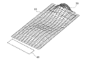
パネル10は、圧電素子30が取り付けられた取付領域だけでなく、取付領域から離れた領域も振動する。パネル10は、振動する領域において、当該パネル10の主面と交差する方向に振動する箇所を複数有し、当該複数の箇所の各々において、振動の振幅の値が、時間とともにプラスからマイナスに、あるいはその逆に変化する。パネル10は、ある瞬間において、振動の振幅が相対的に大きい部分と振動の振幅が相対的に小さい部分とがパネル10の略全体に一見ランダムに分布した振動をする。即ちパネル10全域にわたって、複数の波の振動が検出される。利用者が例えば5N〜10Nの力で自身の体にパネル10を押し付けた場合であっても、パネル10の上述したような振動が減衰しないためには、制御部50が圧電素子30に対して印加する電圧は、±15Vであってよい。そのため、利用者は、上述したパネル10の取付領域から離れた領域に耳を接触させて音を聞くことができる。
The
ここで、パネル10は、利用者の耳とほぼ同じ大きさであってよい。また、パネル10は、図2に示すように、利用者の耳よりも大きいものであってもよい。この場合、利用者が音を聞く際、電子機器1のパネル10により耳全体が覆われやすいことから、周囲音(ノイズ)を外耳道に入りにくくできる。パネル10は、対耳輪下脚(下対輪脚)から対耳珠までの間の距離に相当する長さと、耳珠から対耳輪までの間の距離に相当する幅とを有する領域よりも広い領域が振動すればよい。パネル10は、好ましくは、耳輪における対耳輪上脚(上対輪脚)近傍の部位から耳垂までの間の距離に相当する長さと、耳珠から耳輪における対耳輪近傍の部位までの間の距離に相当する幅を有する領域が振動すればよい。長さ方向は、この例ではパネル10が延在する長手方向2aであり、その中心から一方の端部寄りに圧電素子30が配置される。また、幅方向は、長手方向と直交する方向2hである。かかる長さおよび幅を有する領域は、長方形状の領域であってもよいし、上記の長さを長径、上記の幅を短径とする楕円形状であってもよい。日本人の耳の平均的な大きさは、社団法人 人間生活工学研究センター(HQL)作成の日本人の人体寸法データベース(1992−1994)等を参照すれば知ることができる。尚、パネル10が日本人の耳の平均的な大きさ以上の大きさであれば、パネル10は概ね外国人の耳全体を覆うことができる大きさであると考えられる。
Here, the
上記のような寸法や形状を有することで、パネル10は、ユーザの耳を覆うことができ、耳に当てたときの位置ずれに対して寛容になる。
By having the dimensions and shapes as described above, the
上記の電子機器1は、パネル10の振動により、気導音と、利用者の体の一部(例えば外耳の軟骨)を介する人体振動音とを利用者に伝えることができる。そのため、従来のダイナミックレシーバと同等の音量の音を出力する場合、パネル10が振動することで空気の振動により電子機器1の周囲へ伝わる音は、ダイナミックレシーバと比較して少ない。したがって、例えば録音されたメッセージを電車内等で聞く場合等に適している。
The electronic device 1 can transmit air conduction sound and human body vibration sound through a part of the user's body (for example, cartilage of the outer ear) to the user by the vibration of the
また、上記の電子機器1は、パネル10の振動によって人体振動音を伝えるため、例えば利用者がイヤホンまたはヘッドホンを身につけていても、それらに電子機器1を接触させることで、利用者はイヤホンまたはヘッドホンおよび体の一部を介して音を聞くことができる。
In addition, since the electronic device 1 transmits a human body vibration sound by the vibration of the
上記の電子機器1は、パネル10の振動により利用者に音を伝える。そのため、電子機器1が別途ダイナミックレシーバを備えない場合、音声伝達のための開口部(放音口)を筐体に形成する必要がなく、電子機器1の防水構造が簡略化できる。尚、電子機器1がダイナミックレシーバを備える場合、放音口は、気体は通すが液体は通さない部材によって閉塞されるとよい。気体は通すが液体は通さない部材は、例えばゴアテックス(登録商標)である。
The electronic device 1 transmits sound to the user by the vibration of the
(第1の実施形態)
図3は第1の実施形態に係る電子機器1の実装構造を示す図である。図3(a)は正面図、図3(b)は図3(a)におけるb−b線に沿った断面図である。図3に示す電子機器1はパネル10としてガラス板であるタッチパネルが筐体60(例えば金属や樹脂のケース)の前面に配されたスマートフォンである。パネル10、入力部40、及び制御部50が設けられる回路基板52は筐体60に支持される。入力部40は、筐体60に設けられた開口部310に埋入される操作キーである。
(First embodiment)
FIG. 3 is a diagram illustrating a mounting structure of the electronic device 1 according to the first embodiment. 3A is a front view, and FIG. 3B is a cross-sectional view taken along the line bb in FIG. 3A. The electronic device 1 shown in FIG. 3 is a smartphone in which a touch panel, which is a glass plate, is arranged as a
入力部40である操作キーは、ユーザが押下することで電気的接触が生じて入力信号が生成されるような、可動型の入力手段である。そのため、可動部分にはある程度のあそびが許容される。すると、たとえば、操作キーをパネル10に開口部を設けて埋入させた場合、圧電素子30がパネル10を振動させる際にパネル10の振動が操作キーに伝わり、操作キーががたついて不要な音が生じたり、通話音が漏れたりするおそれがある。そこで、本実施形態では、操作キーをパネル10側ではなく筐体60側に開口部310を設け、そこに埋入するようにした。そうすることで、パネル10の振動はパネル10と筐体60との接合部分や接触部分を介して筐体60に有る程度は伝わるものの、その経路で減衰するので、操作キーをがたつかせるような振動の影響を低減させることができる。
The operation key that is the
さらに、筐体60を伝わる振動は、その発生源である圧電素子30からの距離に応じて減衰する。よって、圧電素子30が、たとえば、長方形状のパネル10の平面視における長手方向300での第1の端部側(図3における上端部側)60aに設けられるとしたとき、操作キーが第1の端部側60aとは反対の第2の端部側(図6における下端部側)60bに設けられる。ここで、第1の端部側60aと第2の端部側60bは、たとえば、長手方向300における長さの中間点302で長手方向と直交する短手方向を境界304として分割される。そして、平面視において、圧電素子30の固定位置が含まれる方が第1の端部側60a、他方が第2の端部側60bに対応する。なお、圧電素子30が境界304を越えて配置される場合には、圧電素子30の面積の半分以上が含まれる側が第1の端部側60a、他方が第2の端部側60bに対応する。
Furthermore, the vibration transmitted through the
このように、圧電素子30が設けられる上部側60aではなく、下部側60bの筐体60に操作キーを設けることで、圧電素子30と同じ上部側60aに設けた場合より、結合部66に伝わる振動を小さくすることができる。よって、より効果的に、操作キーに伝わる振動を抑えることができる。
In this way, by providing the operation key on the
表示部20および圧電素子30は、それぞれ接合部材70によりパネル10に接着されている。表示部20をパネル10に接着する場合、接合部材70は、熱硬化性あるいは紫外線硬化性等を有する接着剤、例えば無色透明のアクリル系紫外線硬化型接着剤である光学弾性樹脂などが好ましい。そうすることで、表示部20は、パネル10を透過して各種表示内容を表示できる。また、圧電素子30をパネル10に接着する場合、接合部材70は、熱硬化性あるいは紫外線硬化性等を有する接着剤や両面テープ等であり、例えば無色透明のアクリル系紫外線硬化型接着剤である光学弾性樹脂でもよい。パネル10、表示部20および圧電素子30は、それぞれ略長方形状である。
The
表示部20は、パネル10の短手方向におけるほぼ中央に配置される。圧電素子30は、パネル10の長手方向の端部から所定の距離だけ離間して、当該端部の近傍に、圧電素子30の長手方向がパネル10の短辺に沿うように配置される。表示部20と圧電素子30とは、パネル10の内部側の面に平行な方向において並んで配置される。
The
図4は、本実施形態に係る電子機器1のパネル10の振動の一例を示す図である。第1の実施形態に係る電子機器1では、表示部20がパネル10に取り付けられている。このため、パネル10の下部は、圧電素子30が取り付けられたパネル10の上部に比して振動しにくくなる。そのため、パネル10の下部において、パネル10の下部が振動することによる音漏れが低減できる。また、表示部20が圧電素子30のパネル10における位置と操作キーである入力部40の筐体60における位置の間に設けられることで、パネル10の下部と筐体60との接触を介して圧電素子30から入力部40へ振動が伝わる経路において、振動を効率よく減衰させることができる。よって、入力部40の操作キーのがたつきを抑えることができる。
FIG. 4 is a diagram illustrating an example of vibration of the
また、本実施形態に係る電子機器1によれば、パネル10の背面に取り付けられた圧電素子30の変形に起因してパネル10が変形し、当該変形するパネル10に接触する対象物に対して気導音と人体振動音とを伝える。これにより、振動体を筐体60の外面に突出させることなく気導音と人体振動音とを利用者に伝えることができるため、筐体に比べて非常に小さな振動体を人体に接触させる特許文献1に記載の電子機器よりも使い勝手が向上する。また、圧電素子自体に利用者の耳を当てる必要がないので圧電素子30そのものが破損しにくい。また、パネル10を振動させた場合には、パネル10ではなく筐体60を変形させて振動を発生させる場合に比較して、利用者が端末を落としにくくできる。
Further, according to the electronic device 1 according to the present embodiment, the
また、圧電素子30はパネル10に接合部材70により接合されている。これにより、圧電素子30の変形の自由度を阻害しにくい状態で圧電素子30をパネル10に取り付けることができる。また、接合部材70は、非加熱型硬化性の接着剤とすることができる。これにより、硬化時に、圧電素子30とパネル10との間に熱応力収縮が発生しにくいという利点がある。また、接合部材70は、両面テープとすることができる。これにより、圧電素子30とパネル10との間に接着剤使用時のような収縮応力がかかりにくいという利点がある。
The
(第2の実施形態)
図5は第2の実施形態に係る電子機器1の実装構造を示す図である。図5(a)は正面図、図5(b)は図5(a)におけるb−b線に沿った断面図、図5(c)は図5(a)におけるc−c線に沿った断面図である。図5に示す電子機器1はパネル10として表示部20を保護するカバーパネル(アクリル板)が上側の筐体60の前面に配された折りたたみ式の携帯電話である。第2の実施形態では、パネル10と圧電素子30との間には、補強部材80が配置される。補強部材80は、例えば樹脂製の板、板金またはガラス繊維を含む樹脂製の板である。すなわち、第2の実施形態に係る電子機器1は、圧電素子30と補強部材80とが接合部材70により接着され、さらに補強部材80とパネル10とが接合部材70により接着される構造である。
(Second Embodiment)
FIG. 5 is a diagram illustrating a mounting structure of the electronic device 1 according to the second embodiment. 5 (a) is a front view, FIG. 5 (b) is a cross-sectional view taken along line bb in FIG. 5 (a), and FIG. 5 (c) is taken along line cc in FIG. 5 (a). It is sectional drawing. The electronic device 1 shown in FIG. 5 is a foldable mobile phone in which a cover panel (acrylic plate) that protects the
また、第2の実施形態では、表示部20は、パネル10に接着されるのではなく、筐体60によって支持されている。すなわち、第2の実施形態に係る電子機器1は、表示部20がパネル10と離間しており、表示部20と筐体60の一部である支持部90とが接合部材70により接着される構造である。なお、支持部90は、筐体60の一部としての構成に限定されず、金属や樹脂等により筐体60から独立した部材として構成することが可能である。そして、筐体60側に、操作キーである入力部40が設けられる。
In the second embodiment, the
図6は、第2の実施形態に係る電子機器1のパネル10の振動の一例を示す図である。第2の実施形態に係る電子機器1では、パネル10がガラス板と比較し剛性の低いアクリル板であり、また、パネル10の背面に表示部20が接着されていないため、図4に示す第1の実施形態に係る電子機器1に比べ、圧電素子30により生じる振幅が大きくなる。また、パネル10は、圧電素子30が取り付けられた取付領域だけでなく、取付領域から離れた領域も振動する。このため、利用者は、空気を介する気導音に加え、パネル10の任意の位置に耳を接触させて人体振動音を聞くことができる。その一方で、操作キーを筐体60側に設けたことにより、パネル10の振動を操作キーに伝わりにくくすることができる。
FIG. 6 is a diagram illustrating an example of vibration of the
このように、本実施形態に係る電子機器1によれば、パネル10に補強部材80を介して取り付けられた圧電素子30の変形に起因して補強部材80およびパネル10が変形し、当該変形するパネル10に接触する対象物に対して気導音と人体振動音とを伝える。これにより、振動体自体を耳に当てることなく気導音と人体振動音とを利用者に伝えることができる。また、圧電素子30は、パネル10の筐体60内部側の面に取り付けられる。このため、振動体を筐体60の外面に突出させることなく気導音と人体振動音とを利用者に伝えることができる。また、パネル10は、圧電素子30が取り付けられた取付領域だけでなく、パネル10のいずれの箇所においても気導音と人体振動音とを伝えるための変形が発生する。このため、利用者は、空気を介する気導音に加え、パネル10の任意の位置に耳を接触させて人体振動音を聞くことができる。
As described above, according to the electronic apparatus 1 according to the present embodiment, the reinforcing
また、圧電素子30とパネル10との間に補強部材80を配置することで、例えばパネル10に外力が加わった場合に、その外力が圧電素子30に伝達され圧電素子30が破損する可能性を低減することができる。また、人体にパネル10を強く接触させても、パネル10の振動が減衰しにくくできる。また、圧電素子30とパネル10との間に補強部材80を配置することで、パネル10の共振周波数が下がり、低周波帯域の音響特性が向上する。なお、補強部材80に換えて、板状の錘を接合部材70により圧電素子30に取り付けてもよい。
Further, by arranging the reinforcing
本発明を諸図面や実施例に基づき説明してきたが、当業者であれば本開示に基づき種々の変形や修正を行うことが容易であることに注意されたい。従って、これらの変形や修正は本発明の範囲に含まれることに留意されたい。例えば、各部材、各ステップなどに含まれる機能などは論理的に矛盾しないように再配置可能であり、複数の構成部やステップなどを1つに組み合わせたり、或いは分割したりすることが可能である。 Although the present invention has been described based on the drawings and examples, it should be noted that those skilled in the art can easily make various modifications and corrections based on the present disclosure. Therefore, it should be noted that these variations and modifications are included in the scope of the present invention. For example, the functions included in each member, each step, etc. can be rearranged so that there is no logical contradiction, and a plurality of components, steps, etc. can be combined into one or divided. is there.
例えば、図7に示すとおり、パネル10が筐体60に接合部材70により接合されている構成としても良い。このように、筐体60にパネル10からの振動がダイレクトに伝わりにくくすることで、筐体自体が大きく振動する場合と比較して、ユーザが電子機器1を落としてしまう恐れを低減できる。また、接合部材70は、非加熱型硬化性の接着剤とすることができる。これにより、硬化時に、筐体60とパネル10との間に熱応力収縮が発生しにくいという利点がある。また、接合部材70は、両面テープとすることができる。これにより、筐体60とパネル10との間に接着剤使用時のような収縮応力が発生しにくいという利点がある。
For example, as illustrated in FIG. 7, the
例えば、パネル10と表示部20とが重畳しない構成である場合、圧電素子30は、パネル10の中央に配設されてもよい。圧電素子30がパネル10の中央に配設された場合、圧電素子30の振動がパネル10全体に均等に伝わり、気導音の品質を向上させたり、利用者が耳をパネル10の様々な位置に接触させても人体振動音を認識させたりすることができる。なお、上述の実施形態と同様に、圧電素子30は複数個搭載してもよい。
For example, when the
また、上記の電子機器1においては、圧電素子30はパネル10に貼り付けられているが、パネル10と異なる場所に取り付けられてもよい。例えば、圧電素子30は、筐体60に取り付けられてバッテリを覆うバッテリリッドに貼り付けられてもよい。バッテリリッドは携帯電話機等の電子機器1においてパネル10と異なる面に取り付けられることが多いため、そのような構成によれば、利用者はパネル10と異なる面に体の一部(例えば耳)を接触させて音を聞くことができる。
In the electronic device 1 described above, the
また、パネル10は、表示パネル、操作パネル、カバーパネル、充電池を取り外し可能とするためのリッドパネルのいずれかの一部または全部を構成することができる。特に、パネル10が表示パネルのとき、圧電素子30は、表示機能のための表示領域の外側に配置される。これにより、表示を阻害しにくいという利点がある。操作パネルは、第1実施形態のタッチパネルを含む。また、操作パネルは、例えば折畳型携帯電話において操作キーのキートップが一体に形成され操作部側筐体の一面を構成する部材であるシートキーを含む。
Further, the
なお、第1の実施形態および第2の実施形態では、パネル10と圧電素子30とを接着する接合部材およびパネル10と筐体60とを接着する接合部材等を同一の符号を有する接合部材70として説明した。しかしながら、第1実施形態および第2実施形態で用いられる接合部材は、接合する対象である部材に応じて適宜異なるものが用いられてよい。
In the first embodiment and the second embodiment, the bonding member that bonds the
1 電子機器
10 パネル
20 表示部
30 圧電素子
40 入力部
50 制御部
60 筐体
70 接合部材
80 補強部材
90 支持部
DESCRIPTION OF SYMBOLS 1
Claims (13)
前記圧電素子が固定される振動板と、
当該振動板が固定される筐体と、
前記筐体に設けられる操作キーと、
を有する電子機器において、
前記圧電素子の長辺方向において該圧電素子の直上がその周囲と比較して最も高く隆起するように、前記圧電素子によって前記振動板が曲げられ、当該振動板に接触している人体の接触部位が振動して音を伝える電子機器であって、
前記圧電素子は、前記振動板の平面視における第1の端部寄りに固定され、
前記操作キーは、前記振動板の平面視における前記第1の端部と反対側の第2の端部側の前記筐体に設けられる、
電子機器。 A piezoelectric element;
A diaphragm to which the piezoelectric element is fixed;
A housing to which the diaphragm is fixed;
An operation key provided on the housing;
In an electronic device having
The contact part of the human body in which the diaphragm is bent by the piezoelectric element and is in contact with the diaphragm so that the upper part of the piezoelectric element protrudes higher than the surrounding in the long side direction of the piezoelectric element. Is an electronic device that vibrates and transmits sound,
The piezoelectric element is fixed near a first end in a plan view of the diaphragm,
The operation key is provided on the housing on the second end side opposite to the first end in a plan view of the diaphragm.
Electronics.
前記振動板における前記圧電素子の固定箇所と前記第2の端部との間の領域に固定される表示部をさらに有する
電子機器。 In claim 1 ,
An electronic apparatus further comprising a display unit fixed to a region between the fixed portion of the piezoelectric element and the second end of the diaphragm.
前記振動板における前記圧電素子の固定箇所は、当該振動板の平面視における表示部との重複領域の外部に位置する、
電子機器。 In claim 2 ,
The fixed location of the piezoelectric element in the diaphragm is located outside the overlapping area with the display unit in plan view of the diaphragm,
Electronics.
前記圧電素子が固定される振動板と、
当該振動板が固定される筐体と、
前記筐体に設けられる操作キーと、
を有する電子機器において、
前記圧電素子の長辺方向において該圧電素子の直上がその周囲と比較して最も高く隆起するように、前記圧電素子によって前記振動板が曲げられ、当該振動板に接触している人体の接触部位が振動して音を伝える電子機器であって、
前記操作キーは、前記筐体に設けられる開口部に埋入される
電子機器。 A piezoelectric element;
A diaphragm to which the piezoelectric element is fixed;
A housing to which the diaphragm is fixed;
An operation key provided on the housing;
In an electronic device having
The contact part of the human body in which the diaphragm is bent by the piezoelectric element and is in contact with the diaphragm so that the upper part of the piezoelectric element protrudes higher than the surrounding in the long side direction of the piezoelectric element. Is an electronic device that vibrates and transmits sound,
The operation key is an electronic device embedded in an opening provided in the housing.
前記圧電素子が固定される振動板と、
当該振動板が固定される筐体と、
前記筐体に設けられる操作キーと、
を有する電子機器において、
前記圧電素子の長辺方向において該圧電素子の直上がその周囲と比較して最も高く隆起するように、前記圧電素子によって前記振動板が曲げられ、当該振動板に接触している人体の接触部位が振動して音を伝える電子機器であって、
前記振動板の平面視における前記圧電素子が固定される側から他方の側へ向かう第2の方向の長さは、対耳珠から対耳輪下脚までの長さ以上である、
電子機器。 A piezoelectric element;
A diaphragm to which the piezoelectric element is fixed;
A housing to which the diaphragm is fixed;
An operation key provided on the housing;
In an electronic device having
The contact part of the human body in which the diaphragm is bent by the piezoelectric element and is in contact with the diaphragm so that the upper part of the piezoelectric element protrudes higher than the surrounding in the long side direction of the piezoelectric element. Is an electronic device that vibrates and transmits sound,
The length in the second direction from the side on which the piezoelectric element is fixed in the plan view of the diaphragm to the other side is equal to or longer than the length from the tragus to the lower leg of the earring,
Electronics.
前記振動板の平面視における前記第2の方向と交差する方向の長さは、耳珠から対耳輪までの長さ以上である、
電子機器。 In claim 5 ,
The length in the direction intersecting the second direction in plan view of the diaphragm is equal to or longer than the length from the tragus to the antiaural ring,
Electronics.
前記圧電素子は、前記振動板に接合部材により接合されて固定される、
電子機器。 In any one of Claims 1 , 4 , and 5 ,
The piezoelectric element is bonded and fixed to the diaphragm by a bonding member.
Electronics.
前記接合部材は、非加熱型硬化性の接着材である、
電子機器。 In claim 7 ,
The joining member is a non-heating type curable adhesive,
Electronics.
前記接合部材は、両面テープである、
電子機器。 In claim 7 ,
The joining member is a double-sided tape,
Electronics.
前記振動板は、前記筐体に接合部材により接合される、
電子機器。 In any one of Claims 1 , 4 , and 5 ,
The diaphragm is joined to the housing by a joining member.
Electronics.
前記接合部材は、非加熱型硬化性の接着材である、
電子機器。 In claim 10 ,
The joining member is a non-heating type curable adhesive,
Electronics.
前記接合部材は、両面テープである、
電子機器。 In claim 10 ,
The joining member is a double-sided tape,
Electronics.
前記振動板は、表示部、入力部、表示部のカバー、及び電池を取り外し可能とするための蓋部のうちいずれかの一部または全部を構成する、
電子機器。 In any one of Claims 1 , 4 , and 5 ,
The diaphragm constitutes a part or all of a display unit, an input unit, a cover of the display unit, and a lid for making the battery removable.
Electronics.
Priority Applications (3)
| Application Number | Priority Date | Filing Date | Title |
|---|---|---|---|
| JP2012089203A JP5968018B2 (en) | 2012-04-10 | 2012-04-10 | Electronics |
| EP13163139.2A EP2651103A3 (en) | 2012-04-10 | 2013-04-10 | Electronic device |
| US13/860,150 US9300770B2 (en) | 2012-04-10 | 2013-04-10 | Electronic device |
Applications Claiming Priority (1)
| Application Number | Priority Date | Filing Date | Title |
|---|---|---|---|
| JP2012089203A JP5968018B2 (en) | 2012-04-10 | 2012-04-10 | Electronics |
Publications (2)
| Publication Number | Publication Date |
|---|---|
| JP2013219584A JP2013219584A (en) | 2013-10-24 |
| JP5968018B2 true JP5968018B2 (en) | 2016-08-10 |
Family
ID=48139716
Family Applications (1)
| Application Number | Title | Priority Date | Filing Date |
|---|---|---|---|
| JP2012089203A Expired - Fee Related JP5968018B2 (en) | 2012-04-10 | 2012-04-10 | Electronics |
Country Status (3)
| Country | Link |
|---|---|
| US (1) | US9300770B2 (en) |
| EP (1) | EP2651103A3 (en) |
| JP (1) | JP5968018B2 (en) |
Families Citing this family (8)
| Publication number | Priority date | Publication date | Assignee | Title |
|---|---|---|---|---|
| JP5968050B2 (en) * | 2012-04-26 | 2016-08-10 | 京セラ株式会社 | Electronics |
| US9380140B2 (en) * | 2012-07-30 | 2016-06-28 | Kyocera Corporation | Electronic apparatus |
| JP5769781B2 (en) * | 2013-10-29 | 2015-08-26 | 京セラ株式会社 | Electronics |
| KR20170114471A (en) | 2016-04-05 | 2017-10-16 | 엘지디스플레이 주식회사 | Organic light emitting display device |
| KR102663406B1 (en) | 2016-04-04 | 2024-05-14 | 엘지디스플레이 주식회사 | Sound generation actuator of panel vibration type and double faced display device with the same |
| US10142739B2 (en) | 2016-03-28 | 2018-11-27 | Lg Display Co., Ltd. | Panel vibration type display device for generating sound |
| KR101704517B1 (en) | 2016-03-28 | 2017-02-09 | 엘지디스플레이 주식회사 | Display device for generating sound by panel vibration type |
| CN110290283B (en) * | 2019-06-03 | 2020-11-03 | 珠海格力电器股份有限公司 | Method and device for controlling vibration and folding screen equipment |
Family Cites Families (64)
| Publication number | Priority date | Publication date | Assignee | Title |
|---|---|---|---|---|
| US3728741A (en) | 1970-12-28 | 1973-04-24 | M Lepor | Noise protective device |
| JPH0246159Y2 (en) | 1985-11-20 | 1990-12-05 | ||
| JPH07296786A (en) | 1994-04-22 | 1995-11-10 | Matsushita Electric Ind Co Ltd | Battery case |
| JPH08223675A (en) | 1995-02-17 | 1996-08-30 | Alpine Electron Inc | Speaker device |
| JPH09247795A (en) | 1996-03-05 | 1997-09-19 | Hokuriku Electric Ind Co Ltd | Piezoelectric transducer and sounding electronic device |
| JP3168946B2 (en) | 1997-06-27 | 2001-05-21 | 岩崎通信機株式会社 | Battery lid waterproof structure for portable electronic devices |
| JP4614534B2 (en) | 1998-07-03 | 2011-01-19 | ニュー トランスデューサーズ リミテッド | Resonant panel loudspeaker |
| GB9818719D0 (en) | 1998-08-28 | 1998-10-21 | New Transducers Ltd | Vubration exciter |
| US6259188B1 (en) * | 1998-08-31 | 2001-07-10 | Projects Unlimited, Inc. | Piezoelectric vibrational and acoustic alert for a personal communication device |
| JP3597061B2 (en) | 1998-11-13 | 2004-12-02 | 日本電気株式会社 | Piezo speaker |
| JP3771086B2 (en) | 1999-06-18 | 2006-04-26 | 三菱電機株式会社 | Portable terminal |
| JP2002027065A (en) | 2000-07-05 | 2002-01-25 | Hitachi Ltd | Portable terminal equipment |
| US6639988B2 (en) | 2000-08-31 | 2003-10-28 | Delphi Technologies, Inc. | Piezo integrated flat speakers for automotive interior panels |
| JP3632594B2 (en) | 2000-11-28 | 2005-03-23 | 日本電気株式会社 | Electronic equipment |
| JP2002185593A (en) | 2000-12-19 | 2002-06-28 | Hitachi Kokusai Electric Inc | Portable telephone |
| US6944482B2 (en) * | 2001-01-22 | 2005-09-13 | Wildseed Ltd. | Visualization supplemented wireless mobile telephony |
| JP2002219413A (en) | 2001-01-30 | 2002-08-06 | Nec Tokin Corp | Multifunctional vibration actuator |
| JP2002232542A (en) * | 2001-02-06 | 2002-08-16 | Taisei Plas Co Ltd | Portable communication equipment |
| JP3709350B2 (en) | 2001-04-06 | 2005-10-26 | 埼玉日本電気株式会社 | Foldable information terminal |
| DE60226098T2 (en) * | 2001-06-28 | 2009-06-18 | Panasonic Corp., Kadoma | Speaker system, mobile terminal and electronic device |
| KR100708818B1 (en) * | 2002-02-18 | 2007-04-17 | 요시미네 다카시 | Diagnostic system and portable telephone device |
| EP2204688B1 (en) * | 2002-09-03 | 2011-10-26 | Sharp Kabushiki Kaisha | Liquid crystal display device having sound output function and the like and an electronic device using the same |
| JP2004187031A (en) * | 2002-12-04 | 2004-07-02 | Temuko Japan:Kk | Mobile phone using bone conduction speaker |
| JP2007502594A (en) * | 2003-05-28 | 2007-02-08 | コーニンクレッカ フィリップス エレクトロニクス エヌ ヴィ | Display speaker |
| US7421088B2 (en) | 2003-08-28 | 2008-09-02 | Motorola, Inc. | Multifunction transducer |
| JP4359757B2 (en) | 2003-09-17 | 2009-11-04 | ソニー株式会社 | Information display device |
| AU2005205632A1 (en) | 2004-01-16 | 2005-07-28 | Temco Japan Co., Ltd. | Portable telephone using bone conduction device |
| JP4361384B2 (en) | 2004-01-29 | 2009-11-11 | セイコーインスツル株式会社 | Portable electronic device with sound reporting function |
| JP2005236352A (en) | 2004-02-17 | 2005-09-02 | Authentic Ltd | Panel type speaker for display device |
| JP4449534B2 (en) | 2004-03-30 | 2010-04-14 | セイコーエプソン株式会社 | Electro-optical device and electronic apparatus |
| JP2005348193A (en) | 2004-06-04 | 2005-12-15 | Nec Tokin Corp | Receiver |
| JP4700323B2 (en) | 2004-10-28 | 2011-06-15 | ホシデン株式会社 | Flat panel speaker |
| JPWO2006059679A1 (en) | 2004-12-02 | 2008-06-05 | 松下電器産業株式会社 | Mobile terminal device |
| JP4507252B2 (en) | 2004-12-27 | 2010-07-21 | シチズン電子株式会社 | Panel type speaker |
| WO2006114985A1 (en) | 2005-04-22 | 2006-11-02 | Sharp Kabushiki Kaisha | Card type device and method for manufacturing same |
| JP4779526B2 (en) | 2005-09-15 | 2011-09-28 | 日本電気株式会社 | Panel speaker |
| JP5208362B2 (en) * | 2005-10-28 | 2013-06-12 | ソニー株式会社 | Electronics |
| JP4924839B2 (en) | 2005-11-02 | 2012-04-25 | 日本電気株式会社 | Speaker, image element protection screen, terminal device casing, and terminal device |
| JP2007180827A (en) | 2005-12-27 | 2007-07-12 | Citizen Electronics Co Ltd | Panel-type speaker |
| JP2007189578A (en) | 2006-01-16 | 2007-07-26 | Nec Tokin Corp | Receiving device and portable telephone |
| JP4861079B2 (en) | 2006-07-10 | 2012-01-25 | Necトーキン株式会社 | Bone conduction receiver |
| KR101353417B1 (en) | 2007-03-16 | 2014-01-22 | 엘지전자 주식회사 | Portable terminal |
| JP2008270879A (en) | 2007-04-16 | 2008-11-06 | Nec Tokin Corp | Receiver |
| JP2009118396A (en) | 2007-11-09 | 2009-05-28 | Nec Tokin Corp | Transceiver apparatus |
| JP2009147410A (en) | 2007-12-11 | 2009-07-02 | Sony Corp | Playback device, playback method and playback system |
| US20100278362A1 (en) | 2007-12-20 | 2010-11-04 | Kim David K J | Method and apparatus to interchange between bone conductive and normal mode in receiver |
| CN101594401B (en) | 2008-05-27 | 2013-06-05 | 深圳富泰宏精密工业有限公司 | Electronic device with receiver |
| WO2009144964A1 (en) * | 2008-05-29 | 2009-12-03 | 株式会社村田製作所 | Piezoelectric speaker, speaker device and tactile feedback device |
| US20100225600A1 (en) * | 2009-03-09 | 2010-09-09 | Motorola Inc. | Display Structure with Direct Piezoelectric Actuation |
| US9316099B2 (en) * | 2009-08-02 | 2016-04-19 | Cameron International Corporation | ARC RFID antenna |
| JP2011091719A (en) * | 2009-10-26 | 2011-05-06 | Authentic Ltd | Flexural oscillating actuator |
| JP5576690B2 (en) | 2010-03-26 | 2014-08-20 | 京セラ株式会社 | Portable wireless device |
| EP2609485B1 (en) | 2010-08-23 | 2021-03-10 | Nokia Technologies Oy | Apparatus and method for providing haptic and audio feedback in a touch sensitive user interface. |
| JP2012065044A (en) | 2010-09-14 | 2012-03-29 | Fujitsu Ltd | Portable terminal device |
| US8279623B2 (en) | 2010-12-22 | 2012-10-02 | Research In Motion Limited | Apparatus for vibrating a portable electronic device |
| JP6133534B2 (en) | 2011-11-18 | 2017-05-24 | 株式会社ファインウェル | Mobile phone and its integrated circuit |
| KR101068254B1 (en) | 2011-02-01 | 2011-09-28 | 주식회사 보니아코퍼레이션 | A communication terminal equipment have the bone conductive |
| US9020168B2 (en) | 2011-08-30 | 2015-04-28 | Nokia Corporation | Apparatus and method for audio delivery with different sound conduction transducers |
| JP2013255212A (en) | 2011-09-13 | 2013-12-19 | Kddi Corp | Telephone call device |
| KR101332553B1 (en) | 2011-12-20 | 2013-11-22 | 엘지전자 주식회사 | Mobile terminal |
| JP2013207601A (en) | 2012-03-28 | 2013-10-07 | Kyocera Corp | Electronic apparatus |
| JP5855508B2 (en) | 2012-03-29 | 2016-02-09 | 京セラ株式会社 | Electronics |
| JP5812926B2 (en) | 2012-04-12 | 2015-11-17 | 京セラ株式会社 | Electronics |
| JP5968061B2 (en) | 2012-05-01 | 2016-08-10 | 京セラ株式会社 | Electronics |
-
2012
- 2012-04-10 JP JP2012089203A patent/JP5968018B2/en not_active Expired - Fee Related
-
2013
- 2013-04-10 US US13/860,150 patent/US9300770B2/en active Active
- 2013-04-10 EP EP13163139.2A patent/EP2651103A3/en not_active Withdrawn
Also Published As
| Publication number | Publication date |
|---|---|
| US20130267278A1 (en) | 2013-10-10 |
| US9300770B2 (en) | 2016-03-29 |
| EP2651103A2 (en) | 2013-10-16 |
| JP2013219584A (en) | 2013-10-24 |
| EP2651103A3 (en) | 2017-03-22 |
Similar Documents
| Publication | Publication Date | Title |
|---|---|---|
| JP5856196B2 (en) | Electronics | |
| JP5818923B2 (en) | Electronics | |
| JP5812925B2 (en) | Electronics | |
| JP5734473B2 (en) | Electronics | |
| JP5818922B2 (en) | Electronics | |
| JP5972042B2 (en) | Electronics | |
| JP5968018B2 (en) | Electronics | |
| JP6075592B2 (en) | Electronics | |
| JP5986417B2 (en) | Electronics | |
| JP2013243615A (en) | Electronic apparatus | |
| JP6169881B2 (en) | Electronics | |
| JP2014216903A5 (en) | ||
| JP6006530B2 (en) | Electronics | |
| JP5847637B2 (en) | Electronics | |
| JP5951355B2 (en) | Electronics | |
| JP5856199B2 (en) | Electronics | |
| JP6073074B2 (en) | Electronics | |
| JP5957279B2 (en) | Electronics | |
| JP2014165831A (en) | Electronic apparatus |
Legal Events
| Date | Code | Title | Description |
|---|---|---|---|
| A621 | Written request for application examination |
Free format text: JAPANESE INTERMEDIATE CODE: A621 Effective date: 20140613 |
|
| A977 | Report on retrieval |
Free format text: JAPANESE INTERMEDIATE CODE: A971007 Effective date: 20141224 |
|
| A131 | Notification of reasons for refusal |
Free format text: JAPANESE INTERMEDIATE CODE: A131 Effective date: 20150210 |
|
| A521 | Request for written amendment filed |
Free format text: JAPANESE INTERMEDIATE CODE: A523 Effective date: 20150409 |
|
| A131 | Notification of reasons for refusal |
Free format text: JAPANESE INTERMEDIATE CODE: A132 Effective date: 20151027 |
|
| A521 | Request for written amendment filed |
Free format text: JAPANESE INTERMEDIATE CODE: A523 Effective date: 20151207 |
|
| TRDD | Decision of grant or rejection written | ||
| A01 | Written decision to grant a patent or to grant a registration (utility model) |
Free format text: JAPANESE INTERMEDIATE CODE: A01 Effective date: 20160628 |
|
| A61 | First payment of annual fees (during grant procedure) |
Free format text: JAPANESE INTERMEDIATE CODE: A61 Effective date: 20160705 |
|
| R150 | Certificate of patent or registration of utility model |
Ref document number: 5968018 Country of ref document: JP Free format text: JAPANESE INTERMEDIATE CODE: R150 |
|
| LAPS | Cancellation because of no payment of annual fees |