WO2013168247A1 - Control device for internal combustion engine equipped with supercharger - Google Patents
Control device for internal combustion engine equipped with supercharger Download PDFInfo
- Publication number
- WO2013168247A1 WO2013168247A1 PCT/JP2012/061901 JP2012061901W WO2013168247A1 WO 2013168247 A1 WO2013168247 A1 WO 2013168247A1 JP 2012061901 W JP2012061901 W JP 2012061901W WO 2013168247 A1 WO2013168247 A1 WO 2013168247A1
- Authority
- WO
- WIPO (PCT)
- Prior art keywords
- internal combustion
- combustion engine
- engine
- wgv
- idle stop
- Prior art date
Links
Images

Classifications
-
- F—MECHANICAL ENGINEERING; LIGHTING; HEATING; WEAPONS; BLASTING
- F02—COMBUSTION ENGINES; HOT-GAS OR COMBUSTION-PRODUCT ENGINE PLANTS
- F02B—INTERNAL-COMBUSTION PISTON ENGINES; COMBUSTION ENGINES IN GENERAL
- F02B37/00—Engines characterised by provision of pumps driven at least for part of the time by exhaust
- F02B37/12—Control of the pumps
- F02B37/18—Control of the pumps by bypassing exhaust from the inlet to the outlet of turbine or to the atmosphere
-
- F—MECHANICAL ENGINEERING; LIGHTING; HEATING; WEAPONS; BLASTING
- F02—COMBUSTION ENGINES; HOT-GAS OR COMBUSTION-PRODUCT ENGINE PLANTS
- F02D—CONTROLLING COMBUSTION ENGINES
- F02D41/00—Electrical control of supply of combustible mixture or its constituents
- F02D41/0002—Controlling intake air
- F02D41/0007—Controlling intake air for control of turbo-charged or super-charged engines
-
- F—MECHANICAL ENGINEERING; LIGHTING; HEATING; WEAPONS; BLASTING
- F02—COMBUSTION ENGINES; HOT-GAS OR COMBUSTION-PRODUCT ENGINE PLANTS
- F02D—CONTROLLING COMBUSTION ENGINES
- F02D41/00—Electrical control of supply of combustible mixture or its constituents
- F02D41/02—Circuit arrangements for generating control signals
- F02D41/04—Introducing corrections for particular operating conditions
- F02D41/042—Introducing corrections for particular operating conditions for stopping the engine
-
- F—MECHANICAL ENGINEERING; LIGHTING; HEATING; WEAPONS; BLASTING
- F02—COMBUSTION ENGINES; HOT-GAS OR COMBUSTION-PRODUCT ENGINE PLANTS
- F02D—CONTROLLING COMBUSTION ENGINES
- F02D41/00—Electrical control of supply of combustible mixture or its constituents
- F02D41/02—Circuit arrangements for generating control signals
- F02D41/04—Introducing corrections for particular operating conditions
- F02D41/06—Introducing corrections for particular operating conditions for engine starting or warming up
- F02D41/062—Introducing corrections for particular operating conditions for engine starting or warming up for starting
- F02D41/065—Introducing corrections for particular operating conditions for engine starting or warming up for starting at hot start or restart
-
- F—MECHANICAL ENGINEERING; LIGHTING; HEATING; WEAPONS; BLASTING
- F02—COMBUSTION ENGINES; HOT-GAS OR COMBUSTION-PRODUCT ENGINE PLANTS
- F02D—CONTROLLING COMBUSTION ENGINES
- F02D2250/00—Engine control related to specific problems or objectives
- F02D2250/34—Control of exhaust back pressure, e.g. for turbocharged engines
-
- F—MECHANICAL ENGINEERING; LIGHTING; HEATING; WEAPONS; BLASTING
- F02—COMBUSTION ENGINES; HOT-GAS OR COMBUSTION-PRODUCT ENGINE PLANTS
- F02N—STARTING OF COMBUSTION ENGINES; STARTING AIDS FOR SUCH ENGINES, NOT OTHERWISE PROVIDED FOR
- F02N11/00—Starting of engines by means of electric motors
- F02N11/08—Circuits or control means specially adapted for starting of engines
- F02N11/0814—Circuits or control means specially adapted for starting of engines comprising means for controlling automatic idle-start-stop
-
- Y—GENERAL TAGGING OF NEW TECHNOLOGICAL DEVELOPMENTS; GENERAL TAGGING OF CROSS-SECTIONAL TECHNOLOGIES SPANNING OVER SEVERAL SECTIONS OF THE IPC; TECHNICAL SUBJECTS COVERED BY FORMER USPC CROSS-REFERENCE ART COLLECTIONS [XRACs] AND DIGESTS
- Y02—TECHNOLOGIES OR APPLICATIONS FOR MITIGATION OR ADAPTATION AGAINST CLIMATE CHANGE
- Y02T—CLIMATE CHANGE MITIGATION TECHNOLOGIES RELATED TO TRANSPORTATION
- Y02T10/00—Road transport of goods or passengers
- Y02T10/10—Internal combustion engine [ICE] based vehicles
- Y02T10/12—Improving ICE efficiencies
Definitions
- This invention relates to a control device for an internal combustion engine with a supercharger.
- Patent Document 1 Japanese Unexamined Patent Publication No. 2011-179336
- the waste gate valve of this publication is driven by a diaphragm type actuator in which supercharging pressure is introduced into a control chamber (diaphragm chamber).
- a supercharging pressure introduction path for guiding the supercharging pressure to the control chamber of the actuator, a first on-off valve provided in the supercharging pressure introduction path, and an intake negative pressure downstream of the throttle valve to the control chamber
- An intake negative pressure introduction path and a second opening / closing valve provided in the intake negative pressure introduction path are provided.
- the waste gate valve is closed by the control for closing the first on-off valve and the control for opening the second on-off valve while the throttle valve is closed (during deceleration).
- Patent Document 2 Japanese Unexamined Patent Application Publication No. 2009-197738
- an engine control system (idle stop system) that automatically stops the engine when idling is known.
- the applicant has recognized the following documents including the above-mentioned documents as related to the present invention.
- acceleration response is improved in acceleration from deceleration.
- the exhaust gate negative pressure disappears (becomes atmospheric pressure) due to the idling stop, and the waste gate valve opens, so that it cannot contribute to improving the acceleration response at the time of restart.
- the present invention has been made in order to solve the above-described problems, and even when idling stop control is executed in an internal combustion engine with a supercharger, high acceleration performance can be achieved at restart after idling stop.
- An object of the present invention is to provide a control device for an internal combustion engine with a supercharger capable of ensuring the above.
- a first invention is a control device for an internal combustion engine with a supercharger, A turbocharger turbine provided in an exhaust passage of the internal combustion engine; A bypass passage connecting the exhaust passage upstream and downstream of the turbine to bypass the turbine; A wastegate valve provided in the bypass passage and capable of arbitrarily opening and closing; Idle stop control means for automatically stopping the internal combustion engine when a predetermined idle stop condition is satisfied; Wastegate valve closing control means for closing the wastegate valve when the internal combustion engine is automatically stopped by the idle stop control means.
- the second invention is the first invention, wherein A waste gate valve opening control means for opening the waste gate valve when the engine start switch shifts from an on state to an off state after the internal combustion engine is automatically stopped by the idle stop control means;
- closing the waste gate valve not only means that the opening degree of the waste gate valve is 0 (that is, the waste gate valve is fully closed), but also the opening degree of the waste gate valve. It is also meant that is made smaller than the opening at that time.
- the waste gate valve when the engine start switch is turned off after the internal combustion engine is automatically stopped, the waste gate valve is opened. Therefore, according to the present invention, it is possible to prevent the waste gate valve from sticking, which is a concern when the internal combustion engine is stopped for a long time. In addition, the catalyst warm-up delay due to the delay in opening the waste gate valve after the next start can be prevented.
- opening the waste gate valve means not only maximizing the opening degree of the waste gate valve (that is, fully opening the waste gate valve), but also the opening degree of the waste gate valve. It also means making it larger than the opening at that time.
- FIG. 1 is a diagram for explaining a system configuration according to the first embodiment of the present invention.
- the system shown in FIG. 1 includes an internal combustion engine (hereinafter simply referred to as an engine) 10.
- the internal combustion engine 10 is mounted on a vehicle or the like and used as a power source.
- the internal combustion engine 10 shown in FIG. 1 is an in-line four-cylinder type, in the present invention, the number of cylinders and the cylinder arrangement are not limited thereto.
- the internal combustion engine 10 is connected to an intake passage 12 for taking air into the cylinder and an exhaust passage 14 for discharging exhaust gas from the cylinder.
- An air cleaner 16 is provided near the inlet of the intake passage 12.
- An air flow meter 18 that outputs a signal corresponding to the flow rate of air sucked into the intake passage 12 is provided downstream of the air cleaner 16.
- the internal combustion engine 10 includes a turbocharger 20 that performs supercharging with the energy of exhaust gas.
- a compressor 20 a of the turbocharger 20 is disposed downstream of the air flow meter 18.
- the turbocharger 20 includes a turbine 20b that is integrally connected to the compressor 20a and rotates by the energy of exhaust gas.
- the compressor 20a is rotationally driven by the exhaust energy of the exhaust gas input to the turbine 20b.
- An intercooler 22 for cooling the air compressed by the compressor 20a is provided downstream of the compressor 20a.
- An electronically controlled throttle valve 24 for adjusting the amount of air flowing through the intake passage 12 is provided downstream of the intercooler 22.
- An intake valve 26 that opens and closes the inside of the cylinder and the intake passage 12 is provided at the downstream end of the intake passage 12.
- Each cylinder of the internal combustion engine 10 is provided with an injector 28 for directly injecting fuel into the cylinder (combustion chamber), and an ignition plug 30 for igniting the air-fuel mixture.
- an exhaust valve 32 that opens and closes between the cylinder and the exhaust passage 14 is provided.
- a turbine 20b that is rotated by the energy of the exhaust gas is disposed downstream of the exhaust valve 32.
- a catalyst 34 for purifying components in the exhaust gas is provided downstream of the turbine 20b.
- the catalyst 34 for example, a three-way catalyst is used.
- a bypass passage 36 that connects the exhaust passage 14 upstream of the turbine 20b and the exhaust passage 14 between the turbine 20b and the catalyst 34 to bypass the turbine 20b is provided.
- an electronically controlled waste gate valve (WGV) 38 is provided in the bypass passage 36.
- the WGV 38 can be arbitrarily controlled to open and close by an actuator such as a motor or a negative pressure diaphragm regardless of the operating state, and can thereby forcibly communicate or block the bypass passage 36.
- the system of this embodiment further includes an ECU (Electronic Control Unit) 50.
- ECU50 is comprised by the arithmetic processing apparatus provided with the memory circuit containing ROM, RAM, etc., for example.
- the crank angle sensor 52 for detecting the crank angle and the crank angular speed
- the accelerator opening for detecting the accelerator opening corresponding to the operation amount of the accelerator pedal of the vehicle.
- Various sensors for detecting the operating state of the internal combustion engine 10 such as an ignition switch 56 having an ON position for energizing the ignition system of the internal combustion engine 10 and an OFF position for not energizing are connected.
- Various actuators for controlling the operation state of the internal combustion engine 10 such as the throttle valve 24, the injector 28, the spark plug 30, and the WGV 38 are connected to the output side of the ECU 50.
- ECU50 controls the driving
- the crank angle and the engine speed are calculated based on the output of the crank angle sensor 52, and the intake air amount is calculated based on the output of the air flow meter 18.
- the engine load is calculated based on the intake air amount, the engine speed, the intake pressure, and the like.
- the fuel injection amount is calculated based on the intake air amount, the load, and the like.
- the fuel injection timing and ignition timing are determined based on the crank angle. When these times arrive, the injector 28 and the spark plug 30 are driven. Thereby, the air-fuel mixture is combusted in the cylinder, and the internal combustion engine 10 can be operated.
- the ECU 50 executes idle stop control for automatically stopping the engine 10 when a predetermined idle stop condition is satisfied. Further, the ECU 50 executes engine restart control for automatically starting the engine 10 when a predetermined engine restart condition is satisfied while the engine is stopped by the idle stop control. As described above, the ECU 50 includes the idle stop and start function 58. As described above, the system of this embodiment is a system including the turbocharger 20, the WGV 38, and the idle stop and start function 58.
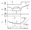
- FIG. 2 is a diagram for explaining characteristic control in the system according to the first embodiment of the present invention.
- the engine 10 is automatically stopped when a predetermined idle stop condition (for example, the accelerator opening is 0 and the engine speed is a specified idle speed) is established.
- a predetermined idle stop condition for example, the accelerator opening is 0 and the engine speed is a specified idle speed
- the accelerator opening (60) becomes 0 at time t0, and then the engine speed (62, 64) decreases to the idle speed, and the engine is automatically stopped at time t1.
- the WGV 38 is in the open state (68)
- the turbo speed (72) is greatly reduced.
- the acceleration performance is deteriorated when accelerating immediately after the engine restart at time t2 (for example, when the engine is restarted and accelerated after an idle stop during a temporary stop due to a signal or the like) (64).
- the WGV 38 when the engine is automatically stopped by the idle stop control, the WGV 38 is controlled to be in the closed state (66). As described above, the WGV 38 can be forcibly controlled by electronic control. By setting the WGV 38 in the closed state at the time of idling stop, the decrease in the turbo rotational speed (70) becomes gentler than in the case where the WGV 38 is in the open state (68) (72). Therefore, high acceleration is ensured when accelerating after engine restart at time t2 (62).
- the WGV 38 may stick or move depending on the oil condition, temperature, and time in that state. In such a case, there is a concern that the catalyst warm-up property may deteriorate due to a delay in opening the WGV 38 at the next engine start.
- the WGV 38 is controlled to be closed. Further, after the engine 10 is automatically stopped, the WGV 38 is controlled to be opened when the ignition switch 56 shifts from the ON state (IG-ON) to the OFF state (IG-OFF) by the operation of the driver. Thereby, it is possible to prevent the WGV 38 from sticking, which is a concern when the engine is stopped for a long time. In addition, the catalyst warm-up delay due to the delay in opening the WGV 38 after the next start can be prevented.
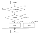
- FIG. 3 is a flowchart of a control routine executed by the ECU 50 in order to realize the above-described operation.
- the idle stop and start function 58 described above is realized in another control routine.
- it is first determined whether or not the engine is stopped (step S100). If the engine is stopped, it is further determined whether the engine is in an “idle stop state” in which the engine 10 is automatically stopped by the idle stop control or an “engine stop state by a driver operation” (step S110). ). Specifically, it is determined whether the ignition switch 56 is in an ON state (IG-ON) or an OFF state (IG-OFF).
- IG-ON ON state
- IG-OFF OFF state
- the ECU 50 controls the WGV 38 to be closed (step S120).
- the ECU 50 controls the WGV 38 to be opened (step S130). Thereafter, the processing of this routine is terminated.
- the WGV 38 can be controlled to be closed in the idle stop state. Therefore, high acceleration can be ensured when the engine 10 is restarted from the idle stop state.
- the WGV 38 can be controlled to be in the open state when the engine is stopped by the operation of the driver. Therefore, the WGV 38 can be prevented from sticking. In addition, the catalyst warm-up delay due to the delay in opening the WGV 38 after the next start can be prevented.
- the engine to which the present invention is applied is not limited to the in-cylinder direct injection engine as in the above-described embodiment.
- the present invention can also be applied to a port injection type engine. Further, the present invention can be applied not only to a spark ignition type engine but also to a compression self-ignition type engine.
- the turbocharger 20 is the “supercharger” in the first invention
- the turbine 20b is the “turbine” in the first invention
- the bypass passage 36 is the first turbocharger.
- the WGV 38 corresponds to the “waste gate valve” in the first invention
- the idle stop and start function 58 corresponds to the “idle stop control means” in the first invention.
- the ECU 50 executes the process of step S120, so that the “waste gate valve closing control means” in the first aspect of the invention executes the process of step S130. “Waste gate valve opening control means” in FIG.
- the “closed state” means “a fully closed state in which the opening degree of the WGV 38 is 0”, but the present invention is not limited to this.
- the WGV 38 may be controlled so that the opening degree of the WGV 38 is smaller than the opening degree at that time.
- the WGV 38 may be controlled so that the opening degree of the WGV 38 is reduced to an opening degree at which sufficient acceleration can be achieved upon subsequent restart.
- “open state” means “a fully open state in which the opening degree of the WGV 38 is maximum”, but the present invention is not limited to this.
- the WGV 38 may be controlled so that the opening degree of the WGV 38 is larger than the opening degree at that time. Preferably, even when the WGV 38 is controlled so that the opening of the WGV 38 can be prevented from sticking while the engine 10 is stopped and the opening of the WGV 38 is sufficient to achieve sufficient catalyst warm-up at the next start. Good.
- the WGV 38 is controlled to be opened when the ignition switch 56 shifts from the ON state to the OFF state by the operation of the driver.
- the WGV 38 may be controlled to be opened when the engine start switch (that is, the switch for starting the internal combustion engine) shifts from the ON state to the OFF state by the operation of the driver.
Abstract
The purpose of the present invention is to provide a control device which is to be used with an internal combustion engine equipped with a supercharger, and is capable of ensuring high acceleration properties when restarting after an idle-stop in an internal combustion engine equipped with a supercharger. The control device is provided with a supercharger turbine positioned in the exhaust channel of the internal combustion engine, a bypass channel for bypassing the turbine and connecting sections of the exhaust channel which are upstream and downstream of the turbine, and a wastegate valve capable of arbitrarily opening/closing and positioned in the bypass valve. In addition, the control device automatically stops the internal combustion engine when a prescribed idle-stop condition is met. The wastegate valve closes when the internal combustion engine is automatically stopped.
Description
この発明は、過給機付き内燃機関の制御装置に関する。
This invention relates to a control device for an internal combustion engine with a supercharger.
従来、例えば特許文献1(日本特開2011-179336号公報)に開示されるように、ウェイストゲートバルブを備えた過給機付き内燃機関が知られている。本公報のウェイストゲートバルブは、制御室(ダイヤフラム室)に過給圧が導入されるダイヤフラム式のアクチュエータによって駆動する。また、アクチュエータの制御室に過給圧を導くための過給圧導入経路と、過給圧導入経路に設けた第1の開閉バルブと、制御室にスロットルバルブ下流の吸気負圧を導くための吸気負圧導入経路と、吸気負圧導入経路に設けた第2の開閉バルブを備える。さらに、スロットルバルブが閉じられる状況下(減速時)で第1の開閉バルブを閉じる制御と共に、第2の開閉バルブを開く制御により、ウェイストゲートバルブを閉弁させる。
Conventionally, as disclosed in, for example, Patent Document 1 (Japanese Unexamined Patent Publication No. 2011-179336), an internal combustion engine with a supercharger provided with a waste gate valve is known. The waste gate valve of this publication is driven by a diaphragm type actuator in which supercharging pressure is introduced into a control chamber (diaphragm chamber). Also, a supercharging pressure introduction path for guiding the supercharging pressure to the control chamber of the actuator, a first on-off valve provided in the supercharging pressure introduction path, and an intake negative pressure downstream of the throttle valve to the control chamber An intake negative pressure introduction path and a second opening / closing valve provided in the intake negative pressure introduction path are provided. Further, the waste gate valve is closed by the control for closing the first on-off valve and the control for opening the second on-off valve while the throttle valve is closed (during deceleration).
また、例えば特許文献2(日本特開2009-197738号公報)に開示されるように、アイドル時にエンジンを自動停止するエンジン制御システム(アイドルストップシステム)が知られている。
尚、出願人は、本発明に関連するものとして、上記の文献を含めて、以下に記載する文献を認識している。 Further, as disclosed in, for example, Patent Document 2 (Japanese Unexamined Patent Application Publication No. 2009-197738), an engine control system (idle stop system) that automatically stops the engine when idling is known.
The applicant has recognized the following documents including the above-mentioned documents as related to the present invention.
特許文献1の構成によれば、減速からの加速において加速レスポンスが改善される。しかしながら、アイドルストップ制御が実行される場合には、アイドルストップにより吸気管負圧が無くなり(大気圧になる)ウェイストゲートバルブが開いてしまうため、再始動時の加速レスポンス改善に貢献できない。
According to the configuration of Patent Document 1, acceleration response is improved in acceleration from deceleration. However, when the idling stop control is executed, the exhaust gate negative pressure disappears (becomes atmospheric pressure) due to the idling stop, and the waste gate valve opens, so that it cannot contribute to improving the acceleration response at the time of restart.
この発明は、上述のような課題を解決するためになされたもので、過給機付き内燃機関においてアイドルストップ制御が実行される場合であっても、アイドルストップ後の再始動時において高い加速性を確保することのできる過給機付き内燃機関の制御装置を提供することを目的とする。
The present invention has been made in order to solve the above-described problems, and even when idling stop control is executed in an internal combustion engine with a supercharger, high acceleration performance can be achieved at restart after idling stop. An object of the present invention is to provide a control device for an internal combustion engine with a supercharger capable of ensuring the above.
第1の発明は、上記の目的を達成するため、過給機付き内燃機関の制御装置であって、
内燃機関の排気通路に設けられた過給機のタービンと、
前記タービンの上流と下流の前記排気通路を接続して前記タービンを迂回するバイパス通路と、
前記バイパス通路に設けられた任意に開閉制御可能なウェイストゲートバルブと、
所定のアイドルストップ条件が成立する場合に、前記内燃機関を自動停止させるアイドルストップ制御手段と、
前記アイドルストップ制御手段により前記内燃機関を自動停止させる場合に、前記ウェイストゲートバルブを閉じるウェイストゲートバルブ閉弁制御手段と、を備えることを特徴とする。 In order to achieve the above object, a first invention is a control device for an internal combustion engine with a supercharger,
A turbocharger turbine provided in an exhaust passage of the internal combustion engine;
A bypass passage connecting the exhaust passage upstream and downstream of the turbine to bypass the turbine;
A wastegate valve provided in the bypass passage and capable of arbitrarily opening and closing;
Idle stop control means for automatically stopping the internal combustion engine when a predetermined idle stop condition is satisfied;
Wastegate valve closing control means for closing the wastegate valve when the internal combustion engine is automatically stopped by the idle stop control means.
また、第2の発明は、第1の発明において、
前記アイドルストップ制御手段により前記内燃機関を自動停止させた後、機関始動スイッチがオン状態からオフ状態に移行した場合に、前記ウェイストゲートバルブを開くウェイストゲートバルブ開弁制御手段、を更に備えることを特徴とする。 The second invention is the first invention, wherein
A waste gate valve opening control means for opening the waste gate valve when the engine start switch shifts from an on state to an off state after the internal combustion engine is automatically stopped by the idle stop control means; Features.
第1の発明によれば、所定のアイドルストップ条件が成立する場合に内燃機関が自動停止するとともに、ウェイストゲートバルブが閉じられる。そのため、本発明によれば、その後の再始動の際に高い加速性を確保することができる。なお、第1の発明において「ウェイストゲートバルブを閉じる」とは、ウェイストゲートバルブの開度を0とする(つまり、ウェイストゲートバルブを全閉とする)ことのみならず、ウェイストゲートバルブの開度をその時の開度よりも小さくすることも意味する。
According to the first invention, when a predetermined idle stop condition is satisfied, the internal combustion engine is automatically stopped and the waste gate valve is closed. Therefore, according to the present invention, high acceleration can be ensured during subsequent restart. In the first aspect of the present invention, “closing the waste gate valve” not only means that the opening degree of the waste gate valve is 0 (that is, the waste gate valve is fully closed), but also the opening degree of the waste gate valve. It is also meant that is made smaller than the opening at that time.
第2の発明によれば、内燃機関が自動停止した後、機関始動スイッチがオフ状態になった場合に、ウェイストゲートバルブが開かれる。そのため、本発明によれば、長時間内燃機関が停止する場合に懸念されるウェイストゲートバルブの固着を防ぐことができる。加えて、次の始動後のウェイストゲートバルブの開き遅れによる触媒暖機遅れを防ぐことができる。なお、第2の発明において「ウェイストゲートバルブを開く」とは、ウェイストゲートバルブの開度を最大とする(つまり、ウェイストゲートバルブを全開とする)ことのみならず、ウェイストゲートバルブの開度をその時の開度よりも大きくすることをも意味する。
According to the second invention, when the engine start switch is turned off after the internal combustion engine is automatically stopped, the waste gate valve is opened. Therefore, according to the present invention, it is possible to prevent the waste gate valve from sticking, which is a concern when the internal combustion engine is stopped for a long time. In addition, the catalyst warm-up delay due to the delay in opening the waste gate valve after the next start can be prevented. In the second invention, “opening the waste gate valve” means not only maximizing the opening degree of the waste gate valve (that is, fully opening the waste gate valve), but also the opening degree of the waste gate valve. It also means making it larger than the opening at that time.
以下、図面を参照して本発明の実施の形態について詳細に説明する。尚、各図において共通する要素には、同一の符号を付して重複する説明を省略する。
Hereinafter, embodiments of the present invention will be described in detail with reference to the drawings. In addition, the same code | symbol is attached | subjected to the element which is common in each figure, and the overlapping description is abbreviate | omitted.
実施の形態1.
[実施の形態1のシステム構成]
図1は、本発明の実施の形態1のシステム構成を説明するための図である。図1に示すシステムは、内燃機関(以下、単にエンジンとも記す。)10を備えている。内燃機関10は、車両等に搭載されその動力源とされる。図1に示す内燃機関10は、直列4気筒型であるが、本発明において、気筒数および気筒配置はこれに限定されるものではない。 Embodiment 1 FIG.
[System Configuration of Embodiment 1]
FIG. 1 is a diagram for explaining a system configuration according to the first embodiment of the present invention. The system shown in FIG. 1 includes an internal combustion engine (hereinafter simply referred to as an engine) 10. Theinternal combustion engine 10 is mounted on a vehicle or the like and used as a power source. Although the internal combustion engine 10 shown in FIG. 1 is an in-line four-cylinder type, in the present invention, the number of cylinders and the cylinder arrangement are not limited thereto.
[実施の形態1のシステム構成]
図1は、本発明の実施の形態1のシステム構成を説明するための図である。図1に示すシステムは、内燃機関(以下、単にエンジンとも記す。)10を備えている。内燃機関10は、車両等に搭載されその動力源とされる。図1に示す内燃機関10は、直列4気筒型であるが、本発明において、気筒数および気筒配置はこれに限定されるものではない。 Embodiment 1 FIG.
[System Configuration of Embodiment 1]
FIG. 1 is a diagram for explaining a system configuration according to the first embodiment of the present invention. The system shown in FIG. 1 includes an internal combustion engine (hereinafter simply referred to as an engine) 10. The
内燃機関10には、空気を筒内に取り込むための吸気通路12と、筒内から排気ガスを排出するための排気通路14とが接続されている。吸気通路12の入口付近には、エアクリーナ16が設けられている。エアクリーナ16の下流には、吸気通路12に吸入される空気の流量に応じた信号を出力するエアフローメータ18が設けられている。
The internal combustion engine 10 is connected to an intake passage 12 for taking air into the cylinder and an exhaust passage 14 for discharging exhaust gas from the cylinder. An air cleaner 16 is provided near the inlet of the intake passage 12. An air flow meter 18 that outputs a signal corresponding to the flow rate of air sucked into the intake passage 12 is provided downstream of the air cleaner 16.
内燃機関10は、排気ガスのエネルギによって過給を行うターボチャージャ20を備えている。エアフローメータ18の下流には、ターボチャージャ20のコンプレッサ20aが配置されている。ターボチャージャ20は、コンプレッサ20aと一体的に連結され排気ガスのエネルギによって回転するタービン20bを備えている。コンプレッサ20aは、タービン20bに入力される排気ガスの排気エネルギによって回転駆動される。
The internal combustion engine 10 includes a turbocharger 20 that performs supercharging with the energy of exhaust gas. A compressor 20 a of the turbocharger 20 is disposed downstream of the air flow meter 18. The turbocharger 20 includes a turbine 20b that is integrally connected to the compressor 20a and rotates by the energy of exhaust gas. The compressor 20a is rotationally driven by the exhaust energy of the exhaust gas input to the turbine 20b.
コンプレッサ20aの下流には、コンプレッサ20aにより圧縮された空気を冷却するインタークーラ22が設けられている。インタークーラ22の下流には、吸気通路12を流れる空気量を調整するための電子制御式のスロットルバルブ24が設けられている。吸気通路12の下流端には、気筒内と吸気通路12との間を開閉する吸気バルブ26が設けられている。
An intercooler 22 for cooling the air compressed by the compressor 20a is provided downstream of the compressor 20a. An electronically controlled throttle valve 24 for adjusting the amount of air flowing through the intake passage 12 is provided downstream of the intercooler 22. An intake valve 26 that opens and closes the inside of the cylinder and the intake passage 12 is provided at the downstream end of the intake passage 12.
内燃機関10の各気筒には、燃料を気筒内(燃焼室内)に直接噴射するインジェクタ28、混合気に点火するための点火プラグ30が設けられている。
Each cylinder of the internal combustion engine 10 is provided with an injector 28 for directly injecting fuel into the cylinder (combustion chamber), and an ignition plug 30 for igniting the air-fuel mixture.
排気通路14の上流端には、気筒内と排気通路14との間を開閉する排気バルブ32が設けられている。排気バルブ32の下流には、排気ガスのエネルギによって回転するタービン20bが配置されている。タービン20bの下流には、排気ガス中の成分を浄化する触媒34が設けられている。触媒34として、例えば三元触媒が用いられる。
At the upstream end of the exhaust passage 14, an exhaust valve 32 that opens and closes between the cylinder and the exhaust passage 14 is provided. A turbine 20b that is rotated by the energy of the exhaust gas is disposed downstream of the exhaust valve 32. A catalyst 34 for purifying components in the exhaust gas is provided downstream of the turbine 20b. As the catalyst 34, for example, a three-way catalyst is used.
タービン20bの近傍には、タービン20bよりも上流の排気通路14と、タービン20bから触媒34までの間の排気通路14とを接続してタービン20bを迂回するバイパス通路36が設けられている。バイパス通路36には、電子制御式のウェイストゲートバルブ(WGV:Waste Gate Valve)38が設けられている。WGV38は、モータや負圧ダイヤフラム等のアクチュエータにより運転状態によらず任意に開閉制御可能であり、これによりバイパス通路36を強制的に連通、遮断することができる。
Near the turbine 20b, a bypass passage 36 that connects the exhaust passage 14 upstream of the turbine 20b and the exhaust passage 14 between the turbine 20b and the catalyst 34 to bypass the turbine 20b is provided. In the bypass passage 36, an electronically controlled waste gate valve (WGV) 38 is provided. The WGV 38 can be arbitrarily controlled to open and close by an actuator such as a motor or a negative pressure diaphragm regardless of the operating state, and can thereby forcibly communicate or block the bypass passage 36.
本実施形態のシステムは、ECU(Electronic Control Unit)50を更に備えている。ECU50は、例えばROM、RAM等を含む記憶回路を備えた演算処理装置により構成されている。ECU50の入力側には、上述したエアフローメータ18の他、クランク角及びクランク角速度を検出するためのクランク角センサ52、車両のアクセルペダルの操作量に対応したアクセル開度を検出するためのアクセル開度センサ54、内燃機関10の点火系に通電を行うON位置と通電を行わないOFF位置とを有するイグニッションスイッチ56等の内燃機関10の運転状態を検出するための各種センサが接続されている。
The system of this embodiment further includes an ECU (Electronic Control Unit) 50. ECU50 is comprised by the arithmetic processing apparatus provided with the memory circuit containing ROM, RAM, etc., for example. On the input side of the ECU 50, in addition to the air flow meter 18, the crank angle sensor 52 for detecting the crank angle and the crank angular speed, and the accelerator opening for detecting the accelerator opening corresponding to the operation amount of the accelerator pedal of the vehicle. Various sensors for detecting the operating state of the internal combustion engine 10 such as an ignition switch 56 having an ON position for energizing the ignition system of the internal combustion engine 10 and an OFF position for not energizing are connected.
ECU50の出力側には、上述したスロットルバルブ24、インジェクタ28、点火プラグ30、WGV38等の内燃機関10の運転状態を制御するための各種アクチュエータが接続されている。
Various actuators for controlling the operation state of the internal combustion engine 10 such as the throttle valve 24, the injector 28, the spark plug 30, and the WGV 38 are connected to the output side of the ECU 50.
ECU50は、各種センサ出力に基づいて、所定のプログラムに従って各種アクチュエータを駆動させることにより、内燃機関10の運転状態を制御する。例えば、クランク角センサ52の出力に基づいてクランク角やエンジン回転数を算出し、エアフローメータ18の出力に基づいて吸入空気量を算出する。また、吸入空気量、エンジン回転数、吸気圧力等に基づいてエンジンの負荷(負荷率)を算出する。吸入空気量、負荷等に基づいて燃料噴射量を算出する。クランク角に基づいて燃料噴射時期や点火時期を決定する。そして、これらの時期が到来したときに、インジェクタ28、点火プラグ30を駆動する。これにより、筒内で混合気を燃焼させ、内燃機関10を運転することができる。
ECU50 controls the driving | running state of the internal combustion engine 10 by driving various actuators according to a predetermined program based on various sensor outputs. For example, the crank angle and the engine speed are calculated based on the output of the crank angle sensor 52, and the intake air amount is calculated based on the output of the air flow meter 18. Further, the engine load (load factor) is calculated based on the intake air amount, the engine speed, the intake pressure, and the like. The fuel injection amount is calculated based on the intake air amount, the load, and the like. The fuel injection timing and ignition timing are determined based on the crank angle. When these times arrive, the injector 28 and the spark plug 30 are driven. Thereby, the air-fuel mixture is combusted in the cylinder, and the internal combustion engine 10 can be operated.
また、ECU50は、所定のアイドルストップ条件が成立した場合に、エンジン10を自動停止するアイドルストップ制御を実行する。また、ECU50は、アイドルストップ制御によるエンジン停止中に所定のエンジン再始動条件が成立した場合に、エンジン10を自動始動するエンジン再始動制御を実行する。このように、ECU50は、アイドルストップアンドスタート機能58を備えている。以上のように、本実施形態のシステムは、ターボチャージャ20、WGV38、アイドルストップアンドスタート機能58を含むシステムである。
Further, the ECU 50 executes idle stop control for automatically stopping the engine 10 when a predetermined idle stop condition is satisfied. Further, the ECU 50 executes engine restart control for automatically starting the engine 10 when a predetermined engine restart condition is satisfied while the engine is stopped by the idle stop control. As described above, the ECU 50 includes the idle stop and start function 58. As described above, the system of this embodiment is a system including the turbocharger 20, the WGV 38, and the idle stop and start function 58.
[実施の形態1における特徴的制御]
図2は、本発明の実施の形態1のシステムにおける特徴的制御について説明するための図である。上述のターボチャージャ付きアイドルストップ車両において、所定のアイドルストップ条件(例えばアクセル開度が0、かつ、エンジン回転数が規定のアイドル回転数である等)が成立するとエンジン10が自動停止される。図2の例では、時刻t0においてアクセル開度(60)が0となり、その後エンジン回転数(62、64)がアイドル回転数まで低下し、時刻t1においてエンジンが自動停止される。このとき、WGV38が開き状態(68)であると、ターボ回転数(72)は大きく低下する。そのため、時刻t2のエンジン再始動直後に加速する場合(信号待ちなどによる一時的な停車時のアイドルストップ後にエンジンを再始動させて加速する場合など)の加速性が悪化する(64)。 [Characteristic Control in Embodiment 1]
FIG. 2 is a diagram for explaining characteristic control in the system according to the first embodiment of the present invention. In the above-described idle stop vehicle with a turbocharger, theengine 10 is automatically stopped when a predetermined idle stop condition (for example, the accelerator opening is 0 and the engine speed is a specified idle speed) is established. In the example of FIG. 2, the accelerator opening (60) becomes 0 at time t0, and then the engine speed (62, 64) decreases to the idle speed, and the engine is automatically stopped at time t1. At this time, if the WGV 38 is in the open state (68), the turbo speed (72) is greatly reduced. For this reason, the acceleration performance is deteriorated when accelerating immediately after the engine restart at time t2 (for example, when the engine is restarted and accelerated after an idle stop during a temporary stop due to a signal or the like) (64).
図2は、本発明の実施の形態1のシステムにおける特徴的制御について説明するための図である。上述のターボチャージャ付きアイドルストップ車両において、所定のアイドルストップ条件(例えばアクセル開度が0、かつ、エンジン回転数が規定のアイドル回転数である等)が成立するとエンジン10が自動停止される。図2の例では、時刻t0においてアクセル開度(60)が0となり、その後エンジン回転数(62、64)がアイドル回転数まで低下し、時刻t1においてエンジンが自動停止される。このとき、WGV38が開き状態(68)であると、ターボ回転数(72)は大きく低下する。そのため、時刻t2のエンジン再始動直後に加速する場合(信号待ちなどによる一時的な停車時のアイドルストップ後にエンジンを再始動させて加速する場合など)の加速性が悪化する(64)。 [Characteristic Control in Embodiment 1]
FIG. 2 is a diagram for explaining characteristic control in the system according to the first embodiment of the present invention. In the above-described idle stop vehicle with a turbocharger, the
そこで、本実施形態のシステムでは、アイドルストップ制御によりエンジンを自動停止させる場合に、WGV38を閉じ状態(66)に制御することとした。上述したように、WGV38は電子制御により強制的に開閉制御可能である。アイドルストップ時にWGV38を閉じ状態とすることで、ターボ回転数(70)の低下は、WGV38が開き状態(68)である場合(72)に比して緩やかになる。そのため、時刻t2のエンジン再始動後に加速する場合において高い加速性が確保される(62)。
Therefore, in the system of this embodiment, when the engine is automatically stopped by the idle stop control, the WGV 38 is controlled to be in the closed state (66). As described above, the WGV 38 can be forcibly controlled by electronic control. By setting the WGV 38 in the closed state at the time of idling stop, the decrease in the turbo rotational speed (70) becomes gentler than in the case where the WGV 38 is in the open state (68) (72). Therefore, high acceleration is ensured when accelerating after engine restart at time t2 (62).
ただし、駐車など長時間エンジンを停止させる場合にまで、WGV38を閉じ状態にすると、その状態でのオイル状況、温度、時間によってWGV38が固着あるいは動きが悪くなる可能性がある。そのような場合には、次のエンジン始動時のWGV38開き遅れによる触媒暖機性の悪化が懸念される。
However, if the WGV 38 is closed until the engine is stopped for a long period of time such as parking, the WGV 38 may stick or move depending on the oil condition, temperature, and time in that state. In such a case, there is a concern that the catalyst warm-up property may deteriorate due to a delay in opening the WGV 38 at the next engine start.
そこで、本実施形態のシステムでは、まず、上述のように、アイドルストップ制御によりエンジン10を自動停止する場合に、WGV38を閉じ状態に制御する。更に、エンジン10の自動停止後に、ドライバの操作によりイグニッションスイッチ56がON状態(IG-ON)からOFF状態(IG-OFF)に移行した場合には、WGV38を開き状態に制御する。これにより、長時間エンジンが停止する場合に懸念されるWGV38の固着を防ぐことができる。加えて、次の始動後のWGV38の開き遅れによる触媒暖機遅れを防ぐことができる。
Therefore, in the system of the present embodiment, first, as described above, when the engine 10 is automatically stopped by the idle stop control, the WGV 38 is controlled to be closed. Further, after the engine 10 is automatically stopped, the WGV 38 is controlled to be opened when the ignition switch 56 shifts from the ON state (IG-ON) to the OFF state (IG-OFF) by the operation of the driver. Thereby, it is possible to prevent the WGV 38 from sticking, which is a concern when the engine is stopped for a long time. In addition, the catalyst warm-up delay due to the delay in opening the WGV 38 after the next start can be prevented.
図3は、上述の動作を実現するために、ECU50が実行する制御ルーチンのフローチャートである。なお、上述したアイドルストップアンドスタート機能58は他の制御ルーチンにおいて実現されている。図3に示すルーチンでは、まず、エンジン停止中であるか否かが判定される(ステップS100)。エンジン停止中である場合には、さらに、アイドルストップ制御によりエンジン10が自動停止された「アイドルストップ状態」と、「ドライバの操作によるエンジン停止状態」のいずれであるかが判定される(ステップS110)。具体的には、イグニッションスイッチ56がON状態(IG-ON)と、OFF状態(IG-OFF)のいずれであるかが判定される。
FIG. 3 is a flowchart of a control routine executed by the ECU 50 in order to realize the above-described operation. The idle stop and start function 58 described above is realized in another control routine. In the routine shown in FIG. 3, it is first determined whether or not the engine is stopped (step S100). If the engine is stopped, it is further determined whether the engine is in an “idle stop state” in which the engine 10 is automatically stopped by the idle stop control or an “engine stop state by a driver operation” (step S110). ). Specifically, it is determined whether the ignition switch 56 is in an ON state (IG-ON) or an OFF state (IG-OFF).
ON状態である場合には、アイドルストップ状態であると判断できる。この場合、ECU50は、WGV38を閉じ状態に制御する(ステップS120)。一方、OFF状態である場合には、ドライバの操作によるエンジン停止状態であると判断できる。この場合には、ECU50は、WGV38を開き状態に制御する(ステップS130)。その後、本ルーチンの処理が終了される。
If it is in the ON state, it can be determined that it is in the idle stop state. In this case, the ECU 50 controls the WGV 38 to be closed (step S120). On the other hand, when the engine is in the OFF state, it can be determined that the engine is stopped by the driver's operation. In this case, the ECU 50 controls the WGV 38 to be opened (step S130). Thereafter, the processing of this routine is terminated.
以上説明したように、図3に示すルーチンによれば、アイドルストップ状態において、WGV38を閉じ状態に制御することができる。そのため、アイドルストップ状態からエンジン10を再始動させる場合に、高い加速性を確保することができる。
As described above, according to the routine shown in FIG. 3, the WGV 38 can be controlled to be closed in the idle stop state. Therefore, high acceleration can be ensured when the engine 10 is restarted from the idle stop state.
また、図3に示すルーチンによれば、ドライバの操作によるエンジン停止状態において、WGV38を開き状態に制御することができる。そのため、WGV38の固着を防ぐことができる。加えて、次の始動後のWGV38の開き遅れによる触媒暖機遅れを防ぐことができる。
Further, according to the routine shown in FIG. 3, the WGV 38 can be controlled to be in the open state when the engine is stopped by the operation of the driver. Therefore, the WGV 38 can be prevented from sticking. In addition, the catalyst warm-up delay due to the delay in opening the WGV 38 after the next start can be prevented.
このように、本実施形態のシステムによれば、アイドルストップ状態からの再始動時における加速レスポンスの維持と、IG-OFF後におけるWGV38の固着防止、触媒暖機遅れの防止を両立させることができる。
As described above, according to the system of the present embodiment, it is possible to maintain both acceleration response at the time of restart from the idle stop state, prevention of sticking of the WGV 38 after IG-OFF, and prevention of catalyst warm-up delay. .
本発明が適用されるエンジンは、上述の実施の形態のような筒内直噴エンジンには限定されない。ポート噴射式のエンジンにも本発明の適用は可能である。また、火花点火式のエンジンに限らず、圧縮自着火式のエンジンにも本発明を適用することができる。
The engine to which the present invention is applied is not limited to the in-cylinder direct injection engine as in the above-described embodiment. The present invention can also be applied to a port injection type engine. Further, the present invention can be applied not only to a spark ignition type engine but also to a compression self-ignition type engine.
尚、上述した実施の形態1においては、ターボチャージャ20が前記第1の発明における「過給機」に、タービン20bが前記第1の発明における「タービン」に、バイパス通路36が前記第1の発明における「バイパス通路」に、WGV38が前記第1の発明における「ウェイストゲートバルブ」に、アイドルストップアンドスタート機能58が前記第1の発明における「アイドルストップ制御手段」に、それぞれ相当している。
また、ここでは、ECU50が、上記ステップS120の処理を実行することにより前記第1の発明における「ウェイストゲートバルブ閉弁制御手段」が、上記ステップS130の処理を実行することにより前記第1の発明における「ウェイストゲートバルブ開弁制御手段」が、それぞれ実現されている。 In the first embodiment described above, theturbocharger 20 is the “supercharger” in the first invention, the turbine 20b is the “turbine” in the first invention, and the bypass passage 36 is the first turbocharger. In the invention, the WGV 38 corresponds to the “waste gate valve” in the first invention, and the idle stop and start function 58 corresponds to the “idle stop control means” in the first invention.
Further, here, theECU 50 executes the process of step S120, so that the “waste gate valve closing control means” in the first aspect of the invention executes the process of step S130. “Waste gate valve opening control means” in FIG.
また、ここでは、ECU50が、上記ステップS120の処理を実行することにより前記第1の発明における「ウェイストゲートバルブ閉弁制御手段」が、上記ステップS130の処理を実行することにより前記第1の発明における「ウェイストゲートバルブ開弁制御手段」が、それぞれ実現されている。 In the first embodiment described above, the
Further, here, the
また、上述した実施の形態1のWGV38に関し、「閉じ状態」とは「WGV38の開度が0である全閉状態」を意味するが、本発明はこれに制限されない。アイドルストップ制御によりエンジン10を自動停止させる場合に、WGV38の開度がその時の開度よりも小さくなるようにWGV38を制御してもよい。好ましくは、WGV38の開度が後の再始動時に十分な加速性を達成可能な開度にまで小さくなるようにWGV38を制御してもよい。さらに、上述した実施の形態1のWGV38に関し、「開き状態」とは「WGV38の開度が最大である全開状態」を意味するが、本発明はこれに制限されない。エンジン10の自動停止後にイグニッションスイッチ56がON状態からOFF状態に移行した場合に、WGV38の開度がその時の開度よりも大きくなるようにWGV38を制御してもよい。好ましくは、WGV38の開度がエンジン10の停止中のWGV38の固着を防ぐことができ且つ次の始動時に十分な触媒暖機が達成可能な開度にまで大きくなるようにWGV38を制御してもよい。
また、上述した実施の形態1では、ドライバの操作によりイグニッションスイッチ56がON状態からOFF状態に移行した場合にWGV38を開き状態に制御している。しかし、本発明では、広くは、ドライバの操作により機関始動スイッチ(すなわち、内燃機関を始動させるスイッチ)がON状態からOFF状態に移行した場合にWGV38を開き状態に制御してもよい。 Further, regarding theWGV 38 of the first embodiment described above, the “closed state” means “a fully closed state in which the opening degree of the WGV 38 is 0”, but the present invention is not limited to this. When the engine 10 is automatically stopped by the idle stop control, the WGV 38 may be controlled so that the opening degree of the WGV 38 is smaller than the opening degree at that time. Preferably, the WGV 38 may be controlled so that the opening degree of the WGV 38 is reduced to an opening degree at which sufficient acceleration can be achieved upon subsequent restart. Furthermore, regarding the WGV 38 of the first embodiment described above, “open state” means “a fully open state in which the opening degree of the WGV 38 is maximum”, but the present invention is not limited to this. When the ignition switch 56 shifts from the ON state to the OFF state after the engine 10 is automatically stopped, the WGV 38 may be controlled so that the opening degree of the WGV 38 is larger than the opening degree at that time. Preferably, even when the WGV 38 is controlled so that the opening of the WGV 38 can be prevented from sticking while the engine 10 is stopped and the opening of the WGV 38 is sufficient to achieve sufficient catalyst warm-up at the next start. Good.
In the first embodiment described above, theWGV 38 is controlled to be opened when the ignition switch 56 shifts from the ON state to the OFF state by the operation of the driver. However, in the present invention, broadly, the WGV 38 may be controlled to be opened when the engine start switch (that is, the switch for starting the internal combustion engine) shifts from the ON state to the OFF state by the operation of the driver.
また、上述した実施の形態1では、ドライバの操作によりイグニッションスイッチ56がON状態からOFF状態に移行した場合にWGV38を開き状態に制御している。しかし、本発明では、広くは、ドライバの操作により機関始動スイッチ(すなわち、内燃機関を始動させるスイッチ)がON状態からOFF状態に移行した場合にWGV38を開き状態に制御してもよい。 Further, regarding the
In the first embodiment described above, the
10 内燃機関(エンジン)
12 吸気通路
14 排気通路
18 エアフローメータ
20 ターボチャージャ
20a コンプレッサ
20b タービン
24 スロットルバルブ
28 インジェクタ
30 点火プラグ
34 触媒
36 バイパス通路
38 ウェイストゲートバルブ(WGV)
50 ECU
52 クランク角センサ
54 アクセル開度センサ
56 イグニッションスイッチ
58 アイドルストップアンドスタート機能
60 アクセル開度の変化(本発明、比較対象)
62 エンジン回転数の変化(本発明)
64 エンジン回転数の変化(比較対象)
66 WGVの制御状態(本発明)
68 WGVの制御状態(比較対象)
70 ターボ回転数の変化(本発明)
72 ターボ回転数の変化(比較対象) 10 Internal combustion engine
12Intake passage 14 Exhaust passage 18 Air flow meter 20 Turbocharger 20a Compressor 20b Turbine 24 Throttle valve 28 Injector 30 Spark plug 34 Catalyst 36 Bypass passage 38 Waste gate valve (WGV)
50 ECU
52Crank angle sensor 54 Accelerator opening sensor 56 Ignition switch 58 Idle stop and start function 60 Accelerator opening change (present invention, comparison object)
62 Changes in engine speed (present invention)
64 Changes in engine speed (for comparison)
66 Control state of WGV (present invention)
68 WGV control status (comparison target)
70 Change in turbo speed (present invention)
72 Change in turbo speed (comparison target)
12 吸気通路
14 排気通路
18 エアフローメータ
20 ターボチャージャ
20a コンプレッサ
20b タービン
24 スロットルバルブ
28 インジェクタ
30 点火プラグ
34 触媒
36 バイパス通路
38 ウェイストゲートバルブ(WGV)
50 ECU
52 クランク角センサ
54 アクセル開度センサ
56 イグニッションスイッチ
58 アイドルストップアンドスタート機能
60 アクセル開度の変化(本発明、比較対象)
62 エンジン回転数の変化(本発明)
64 エンジン回転数の変化(比較対象)
66 WGVの制御状態(本発明)
68 WGVの制御状態(比較対象)
70 ターボ回転数の変化(本発明)
72 ターボ回転数の変化(比較対象) 10 Internal combustion engine
12
50 ECU
52
62 Changes in engine speed (present invention)
64 Changes in engine speed (for comparison)
66 Control state of WGV (present invention)
68 WGV control status (comparison target)
70 Change in turbo speed (present invention)
72 Change in turbo speed (comparison target)
Claims (2)
- 内燃機関の排気通路に設けられた過給機のタービンと、
前記タービンの上流と下流の前記排気通路を接続して前記タービンを迂回するバイパス通路と、
前記バイパス通路に設けられた任意に開閉制御可能なウェイストゲートバルブと、
所定のアイドルストップ条件が成立する場合に、前記内燃機関を自動停止させるアイドルストップ制御手段と、
前記アイドルストップ制御手段により前記内燃機関を自動停止させる場合に、前記ウェイストゲートバルブを閉じるウェイストゲートバルブ閉弁制御手段と、
を備えることを特徴とする過給機付き内燃機関の制御装置。 A turbocharger turbine provided in an exhaust passage of the internal combustion engine;
A bypass passage connecting the exhaust passage upstream and downstream of the turbine to bypass the turbine;
A wastegate valve provided in the bypass passage and capable of arbitrarily opening and closing;
Idle stop control means for automatically stopping the internal combustion engine when a predetermined idle stop condition is satisfied;
Waste gate valve closing control means for closing the waste gate valve when the internal combustion engine is automatically stopped by the idle stop control means;
A control device for an internal combustion engine with a supercharger. - 前記アイドルストップ制御手段により前記内燃機関を自動停止させた後、機関始動スイッチがオン状態からオフ状態に移行した場合に、前記ウェイストゲートバルブを開くウェイストゲートバルブ開弁制御手段、
を更に備えることを特徴とする請求項1記載の過給機付き内燃機関の制御装置。 Waste gate valve opening control means for opening the waste gate valve when the engine start switch shifts from an on state to an off state after the internal combustion engine is automatically stopped by the idle stop control means,
The control device for an internal combustion engine with a supercharger according to claim 1, further comprising:
Priority Applications (1)
| Application Number | Priority Date | Filing Date | Title |
|---|---|---|---|
| PCT/JP2012/061901 WO2013168247A1 (en) | 2012-05-09 | 2012-05-09 | Control device for internal combustion engine equipped with supercharger |
Applications Claiming Priority (1)
| Application Number | Priority Date | Filing Date | Title |
|---|---|---|---|
| PCT/JP2012/061901 WO2013168247A1 (en) | 2012-05-09 | 2012-05-09 | Control device for internal combustion engine equipped with supercharger |
Publications (1)
| Publication Number | Publication Date |
|---|---|
| WO2013168247A1 true WO2013168247A1 (en) | 2013-11-14 |
Family
ID=49550332
Family Applications (1)
| Application Number | Title | Priority Date | Filing Date |
|---|---|---|---|
| PCT/JP2012/061901 WO2013168247A1 (en) | 2012-05-09 | 2012-05-09 | Control device for internal combustion engine equipped with supercharger |
Country Status (1)
| Country | Link |
|---|---|
| WO (1) | WO2013168247A1 (en) |
Cited By (1)
| Publication number | Priority date | Publication date | Assignee | Title |
|---|---|---|---|---|
| JP2016011632A (en) * | 2014-06-30 | 2016-01-21 | 日産自動車株式会社 | Internal combustion engine control unit |
Citations (5)
| Publication number | Priority date | Publication date | Assignee | Title |
|---|---|---|---|---|
| JPH03100325A (en) * | 1989-09-13 | 1991-04-25 | Mazda Motor Corp | Control device of engine with supercharger |
| JP2008180176A (en) * | 2007-01-25 | 2008-08-07 | Toyota Motor Corp | Exhaust system for multiple cylinder internal combustion engine |
| JP2009197738A (en) * | 2008-02-22 | 2009-09-03 | Mazda Motor Corp | Automatic stop device for engine |
| JP2011179336A (en) * | 2010-02-26 | 2011-09-15 | Daihatsu Motor Co Ltd | Supercharging system for internal combustion engine |
| JP2011214413A (en) * | 2010-03-31 | 2011-10-27 | Mazda Motor Corp | Automatic stop device of diesel engine |
-
2012
- 2012-05-09 WO PCT/JP2012/061901 patent/WO2013168247A1/en active Application Filing
Patent Citations (5)
| Publication number | Priority date | Publication date | Assignee | Title |
|---|---|---|---|---|
| JPH03100325A (en) * | 1989-09-13 | 1991-04-25 | Mazda Motor Corp | Control device of engine with supercharger |
| JP2008180176A (en) * | 2007-01-25 | 2008-08-07 | Toyota Motor Corp | Exhaust system for multiple cylinder internal combustion engine |
| JP2009197738A (en) * | 2008-02-22 | 2009-09-03 | Mazda Motor Corp | Automatic stop device for engine |
| JP2011179336A (en) * | 2010-02-26 | 2011-09-15 | Daihatsu Motor Co Ltd | Supercharging system for internal combustion engine |
| JP2011214413A (en) * | 2010-03-31 | 2011-10-27 | Mazda Motor Corp | Automatic stop device of diesel engine |
Cited By (1)
| Publication number | Priority date | Publication date | Assignee | Title |
|---|---|---|---|---|
| JP2016011632A (en) * | 2014-06-30 | 2016-01-21 | 日産自動車株式会社 | Internal combustion engine control unit |
Similar Documents
| Publication | Publication Date | Title |
|---|---|---|
| JP5293897B2 (en) | Control device for internal combustion engine | |
| US8978378B2 (en) | Method and system for reducing turbocharger noise during cold start | |
| EP2963263B1 (en) | Control device for internal combustion engine | |
| JP5672417B2 (en) | Control device and control method for internal combustion engine | |
| WO2012137345A1 (en) | Supercharger-equipped internal combustion engine control apparatus | |
| JP6275181B2 (en) | Electric wastegate valve controller | |
| WO2011033686A1 (en) | Control valve abnormality determination device for internal combustion engine | |
| JP4941534B2 (en) | Wastegate valve control device for internal combustion engine | |
| WO2013118263A1 (en) | Control device for internal combustion engine | |
| JP4419894B2 (en) | Wastegate valve control device for internal combustion engine | |
| JP2015132204A (en) | Internal combustion engine valve reference position learning device | |
| EP2669497A1 (en) | Control device for supercharger-equipped internal combustion engine | |
| US20150247446A1 (en) | Method for Operating a Spark Ignition Internal Combustion Engine with an Exhaust Gas Turbocharger | |
| JP5649343B2 (en) | Intake throttle control method for internal combustion engine | |
| JP6132092B2 (en) | Engine control device | |
| JP5381653B2 (en) | Control device for an internal combustion engine with a supercharger | |
| JP2008075589A (en) | Egr gas scavenging device for internal combustion engine | |
| JP2007303294A (en) | Control device for internal combustion engine with supercharger | |
| JP2011190771A (en) | Control device for internal combustion engine | |
| JP6772901B2 (en) | Internal combustion engine exhaust system | |
| WO2013168247A1 (en) | Control device for internal combustion engine equipped with supercharger | |
| JP5930288B2 (en) | Internal combustion engine | |
| JP2012188994A (en) | Control apparatus for internal combustion engine with supercharger | |
| JP2014231821A (en) | Controller for internal combustion engine equipped with supercharger | |
| JP2006017053A (en) | Fuel injection timing control device for internal combustion engine with supercharger |
Legal Events
| Date | Code | Title | Description |
|---|---|---|---|
| 121 | Ep: the epo has been informed by wipo that ep was designated in this application |
Ref document number: 12876237 Country of ref document: EP Kind code of ref document: A1 |
|
| NENP | Non-entry into the national phase |
Ref country code: DE |
|
| 122 | Ep: pct application non-entry in european phase |
Ref document number: 12876237 Country of ref document: EP Kind code of ref document: A1 |
|
| NENP | Non-entry into the national phase |
Ref country code: JP |