WO2013164879A1 - Energy storage battery - Google Patents
Energy storage battery Download PDFInfo
- Publication number
- WO2013164879A1 WO2013164879A1 PCT/JP2012/061546 JP2012061546W WO2013164879A1 WO 2013164879 A1 WO2013164879 A1 WO 2013164879A1 JP 2012061546 W JP2012061546 W JP 2012061546W WO 2013164879 A1 WO2013164879 A1 WO 2013164879A1
- Authority
- WO
- WIPO (PCT)
- Prior art keywords
- positive electrode
- electrode electrolyte
- aqueous solution
- mol
- polyethyleneimine
- Prior art date
Links
Images


Classifications
-
- H—ELECTRICITY
- H01—ELECTRIC ELEMENTS
- H01M—PROCESSES OR MEANS, e.g. BATTERIES, FOR THE DIRECT CONVERSION OF CHEMICAL ENERGY INTO ELECTRICAL ENERGY
- H01M8/00—Fuel cells; Manufacture thereof
- H01M8/20—Indirect fuel cells, e.g. fuel cells with redox couple being irreversible
-
- H—ELECTRICITY
- H01—ELECTRIC ELEMENTS
- H01M—PROCESSES OR MEANS, e.g. BATTERIES, FOR THE DIRECT CONVERSION OF CHEMICAL ENERGY INTO ELECTRICAL ENERGY
- H01M8/00—Fuel cells; Manufacture thereof
- H01M8/18—Regenerative fuel cells, e.g. redox flow batteries or secondary fuel cells
- H01M8/184—Regeneration by electrochemical means
- H01M8/188—Regeneration by electrochemical means by recharging of redox couples containing fluids; Redox flow type batteries
-
- H—ELECTRICITY
- H01—ELECTRIC ELEMENTS
- H01M—PROCESSES OR MEANS, e.g. BATTERIES, FOR THE DIRECT CONVERSION OF CHEMICAL ENERGY INTO ELECTRICAL ENERGY
- H01M4/00—Electrodes
- H01M4/02—Electrodes composed of, or comprising, active material
- H01M4/36—Selection of substances as active materials, active masses, active liquids
- H01M4/60—Selection of substances as active materials, active masses, active liquids of organic compounds
- H01M4/602—Polymers
- H01M4/604—Polymers containing aliphatic main chain polymers
-
- Y—GENERAL TAGGING OF NEW TECHNOLOGICAL DEVELOPMENTS; GENERAL TAGGING OF CROSS-SECTIONAL TECHNOLOGIES SPANNING OVER SEVERAL SECTIONS OF THE IPC; TECHNICAL SUBJECTS COVERED BY FORMER USPC CROSS-REFERENCE ART COLLECTIONS [XRACs] AND DIGESTS
- Y02—TECHNOLOGIES OR APPLICATIONS FOR MITIGATION OR ADAPTATION AGAINST CLIMATE CHANGE
- Y02E—REDUCTION OF GREENHOUSE GAS [GHG] EMISSIONS, RELATED TO ENERGY GENERATION, TRANSMISSION OR DISTRIBUTION
- Y02E60/00—Enabling technologies; Technologies with a potential or indirect contribution to GHG emissions mitigation
- Y02E60/10—Energy storage using batteries
-
- Y—GENERAL TAGGING OF NEW TECHNOLOGICAL DEVELOPMENTS; GENERAL TAGGING OF CROSS-SECTIONAL TECHNOLOGIES SPANNING OVER SEVERAL SECTIONS OF THE IPC; TECHNICAL SUBJECTS COVERED BY FORMER USPC CROSS-REFERENCE ART COLLECTIONS [XRACs] AND DIGESTS
- Y02—TECHNOLOGIES OR APPLICATIONS FOR MITIGATION OR ADAPTATION AGAINST CLIMATE CHANGE
- Y02E—REDUCTION OF GREENHOUSE GAS [GHG] EMISSIONS, RELATED TO ENERGY GENERATION, TRANSMISSION OR DISTRIBUTION
- Y02E60/00—Enabling technologies; Technologies with a potential or indirect contribution to GHG emissions mitigation
- Y02E60/30—Hydrogen technology
- Y02E60/50—Fuel cells
Definitions
- the present invention relates to a power storage battery such as a redox flow battery.
- Patent Document 1 proposes a configuration in which the negative electrode electrolyte is an aqueous solution containing an iron redox-based material as an active material on the negative electrode side and containing a chelating agent or a complexing agent for shifting the potential to the negative side.
- the positive electrode electrolyte is an aqueous solution containing a manganese redox-based material as an active material on the positive electrode side.
- manganese oxide has a strong oxidizing power and decomposes (oxidizes) a wide range of organic substances in water. Therefore, potassium permanganate, which is a kind of manganese oxide, is used as an oxidizing agent for measuring the amount of organic matter in water, that is, the COD value (see Non-Patent Document 1). Manganese ions also have a strong oxidizing power.
- Non-Patent Document 2 Even in the case of Mn (III) -EDTA (ethylenediaminetetraacetic acid) complex that is complexed with a chelating agent or a complexing agent, the ligand is oxidized to generate carbon dioxide gas, and self-decomposition It is known that this occurs (see Non-Patent Document 2).
- Mn (III) -EDTA ethylenediaminetetraacetic acid
- Patent Document 2 proposes the use of a chelating agent or a complexing agent in order to prevent precipitation of manganese compounds.
- Patent Document 3 proposes the use of a chelating agent or a complexing agent in order to improve the reactivity of manganese ions in the positive electrode electrolyte of a microbial battery.
- JP 56-42970 (published April 21, 1981) JP 57-9073 (published January 18, 1982) JP 2009-23130 (released Oct. 8, 2009)
- MSDS “MSDS / Reagent website (http://www.wako-chem.co.jp/siyaku/msds.htm)” Ethylenediamine (reference number: JW050093) Product Safety Data Sheet (MSDS) : September 1, 2001, Revised date: October 14, 2010)
- Patent Documents 2 and 3 have the disadvantage that many types of chelating agents and complexing agents are decomposed by the oxidizing power of manganese ions. If the chelating agent or complexing agent is decomposed by the oxidizing power of manganese ions contained in the positive electrode electrolyte, the redox flow battery will self-discharge, which reduces the energy efficiency of the redox flow battery. have. Further, since the chelating agent and the complexing agent are reduced, the manganese compound is easily precipitated, and the reactivity of manganese ions is lowered. For this reason, there also exists a problem that the performance of a redox flow type battery falls. Therefore, a redox flow battery using a manganese redox-based material has not yet been put into practical use.
- the present invention has been made in view of the above-mentioned problems, and its main purpose is to use a redox flow battery having sufficient durability to be widely put into practical use using a manganese redox-based material. It is to provide a power storage battery.
- the inventor of the present application diligently studied chelating agents and complexing agents that can withstand the oxidizing power of manganese ions (not decomposed (oxidized)). As a result, only polyethyleneimine can withstand the oxidizing power of manganese ions (not decomposed (oxidized)), can prevent precipitation of manganese compounds, and can prevent self-discharge of power storage batteries.
- the present invention has been completed.
- the power storage battery according to the present invention is a redox type power storage battery in which the positive electrode electrolyte contains a manganese redox-based material as an active material on the positive electrode side and polyethyleneimine. It is characterized by being an aqueous solution containing.
- the positive electrode electrolyte is an aqueous solution containing polyethyleneimine
- precipitation of the manganese compound can be prevented, self-discharge of the power storage battery can be prevented, and the reactivity of manganese ions can be prevented.
- the molar ratio between manganese ions and nitrogen atoms contained in polyethyleneimine is more preferably in the range of 1: 1 to 1: 5.
- the nitrogen atom contained in polyethyleneimine refers to a nitrogen atom contained in ethyleneimine (—CH 2 CH 2 NH—) which is a basic unit.
- ethyleneimine —CH 2 CH 2 NH—
- the reactivity of manganese ions is most improved when the molar ratio is 1: 1, and when used near 60 ° C. It was found that the reactivity of manganese ions was most improved when the molar ratio was 1: 5. Therefore, according to the above configuration, it is possible to provide a power storage battery in which the reactivity of manganese ions is further improved.
- the concentration of the manganese-polyethyleneimine complex contained in the positive electrode electrolyte is more preferably 0.2 mol / L or more and 2.5 mol / L or less.
- the pH of the positive electrode electrolyte is more preferably in the range of 2-7.
- the manganese redox material is more preferably manganese sulfate.
- the positive electrode electrolyte contains chlorine ions, chlorine gas is generated when manganese ions are oxidized by charging the power storage battery. If the positive electrode electrolyte contains an organic substance, the organic substance is decomposed by the oxidizing power of manganese ions, and the power storage battery self-discharges. However, manganese sulfate does not contain chlorine ions or organic substances. Therefore, according to the above configuration, it is possible to provide a power storage battery that does not generate chlorine gas and that can further prevent self-discharge.
- the positive electrode electrolyte is more preferably electrolytically oxidized.
- manganese redox-based substance is manganese (II) sulfate
- manganese (II) sulfate manganese ions generated when polyethyleneimine is dissolved in an aqueous solution containing manganese (II) sulfate is considered to be divalent.
- the valence of manganese ions changes between divalent and trivalent during the redox reaction.
- an aqueous solution containing divalent manganese ions is electrolytically oxidized, most of the manganese ions are considered to be trivalent (however, the exact valence (valence distribution) is unknown).
- the manganese ion contained in the positive electrode electrolyte obtained by electrolytic oxidation of an aqueous solution containing manganese ions changes in valence between trivalent and tetravalent during the redox reaction. Therefore, according to the above configuration, precipitation of the manganese compound can be further prevented, self-discharge of the power storage battery can be further prevented, and the reactivity of the manganese ion can be further improved.
- a storage battery can be provided.
- the positive electrode electrolyte is more preferably shielded from oxygen in the atmosphere.
- a storage battery can be provided.
- the negative electrode electrolyte is more preferably an aqueous solution containing an iron redox-based material as an active material on the negative electrode side.
- the negative electrode electrolyte is more preferably an aqueous solution containing an iron-diethylenetriaminepentaacetic acid complex.
- it is more preferable that the negative electrode electrolyte is electrolytically oxidized.
- the power storage battery according to the present invention is more preferably a redox flow battery.
- a power storage battery that can prevent precipitation of a manganese compound, can prevent self-discharge of the power storage battery, and has improved manganese ion reactivity. be able to. Therefore, it is possible to provide a power storage battery having sufficient durability to be widely put into practical use by using a manganese redox material.
- Example 4 is a graph showing electrode characteristics at 20 ° C. of an electrode immersed in the positive electrode electrolyte b obtained in Example 3.
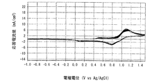
- 6 is a graph showing electrode characteristics at 60 ° C. of an electrode immersed in the positive electrode electrolyte b obtained in Example 3.
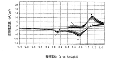
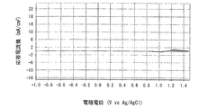
- 6 is a graph showing the electrode characteristics of an electrode immersed in the positive electrode electrolyte c-1 obtained in Example 4.
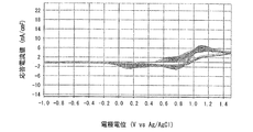
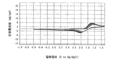
- 6 is a graph showing electrode characteristics of an electrode immersed in the positive electrode electrolyte c-2 obtained in Example 4.
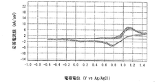
- 6 is a graph showing electrode characteristics of an electrode immersed in the positive electrode electrolyte c-3 obtained in Example 4.
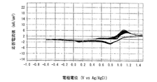
- 6 is a graph showing electrode characteristics of an electrode immersed in a positive electrode electrolyte c-4 obtained in Example 4.
- FIG. 4 is a graph showing “electrolyte utilization” of the redox flow battery of Example 2 and “electrolyte utilization” of the redox flow battery of Comparative Example 10.
- FIG. 4 is a graph showing “electrolyte utilization” of the redox flow battery of Example 2 and “electrolyte utilization” of the redox flow battery of Comparative Example 10.
- the power storage battery according to the present invention is a redox-type power storage battery in which the positive electrode electrolyte is an aqueous solution containing a manganese redox-based material as an active material on the positive electrode side and containing polyethyleneimine.
- the “manganese redox substance” refers to a compound that generates manganese ions whose valence changes in an ionic state during redox reaction (participates in redox reaction). The same applies to iron.
- the description “A to B” indicating a numerical range indicates “A or more and B or less” unless otherwise specified. Accordingly, in the present invention, for example, “pH 2 to 7” means that the pH is 2 or more and 7 or less.
- the “number of moles of polyethyleneimine” refers to the number of moles of nitrogen atoms contained in the basic unit ethyleneimine (—CH 2 CH 2 NH—).
- one mole of polyethyleneimine means that the number of moles of nitrogen atoms contained in the basic unit ethyleneimine (molecular weight 43) is one mole, that is, the number of moles of ethyleneimine is one mole. (Hence, “polyethyleneimine 1 mol” is 43 g).
- a redox flow battery is taken as an example of the power storage battery.
- the present invention is not limited to this, and can be implemented in a mode in which various modifications are added within the range described.
- the redox flow battery 1 As shown in FIG. 1, the redox flow battery 1 according to the present embodiment mainly includes a charge / discharge cell (battery container) 2, a positive electrode electrolyte tank 3, and a negative electrode electrolyte tank 4.
- the inside of the charge / discharge cell 2 is partitioned into a positive electrode side cell 2a and a negative electrode side cell 2b by a diaphragm 11 made of, for example, an ion exchange membrane.
- the charge / discharge cell 2 may be provided with a temperature control device that keeps the temperature constant.
- the positive electrode side cell 2a accommodates a current collector plate 12 such as a glassy carbon plate and a positive electrode 13 made of, for example, carbon felt.
- the negative electrode side cell 2b accommodates a current collector plate 14 such as a glassy carbon plate and a negative electrode 15 made of, for example, carbon felt.
- the positive electrode 13 is impregnated with a positive electrode electrolyte
- the negative electrode 15 is impregnated with a negative electrode electrolyte.
- the positive electrode electrolyte and the negative electrode electrolyte have a pH in the range of 2 to 7, are not strongly acidic, and are poor in corrosiveness, so that they are excellent in handleability.
- the current collecting plates 12 and 14 are electrically connected to the charging / discharging device 10.
- the positive electrode 13 performs a reduction reaction and receives electrons
- the negative electrode 15 performs an oxidation reaction and emits electrons.
- the current collecting plate 12 receives electrons from the charging / discharging device 10 and supplies them to the positive electrode 13, and the current collecting plate 14 collects electrons emitted from the negative electrode 15 and collects them in the charging / discharging device 10. It comes to supply.
- the positive electrode 13 performs an oxidation reaction and emits electrons
- the negative electrode 15 performs a reduction reaction and receives electrons.
- the current collector 12 collects the electrons emitted from the positive electrode 13 and supplies them to the charging / discharging device 10.
- the current collector 14 receives the electrons from the charging / discharging device 10 and supplies them to the negative electrode 15. It comes to supply.
- the positive electrode electrolyte tank 3 is a tank for storing the positive electrode electrolyte, and is connected to the positive electrode side cell 2a. That is, the positive electrode electrolyte tank 3 supplies the positive electrode electrolyte to the positive electrode 13 in the positive electrode side cell 2a through the supply pipe 3a, and the positive electrode electrolyte that has passed through the positive electrode 13 passes through the recovery pipe 3b. It comes to collect.
- the positive electrode electrolyte is circulated by a pump 5 provided in the supply pipe 3a.
- the supply amount of the positive electrode electrolyte per unit time to the positive electrode side cell 2a at the time of charge / discharge and the capacity of the positive electrode electrolyte tank 3 depend on the size of the charge / discharge cell 2, the capacity required for the redox flow battery 1 and the like. There is no particular limitation.
- the negative electrode electrolyte tank 4 is a tank for storing the negative electrode electrolyte, and is connected to the negative electrode side cell 2b. That is, the negative electrode electrolyte tank 4 supplies the negative electrode electrolyte to the negative electrode 15 in the negative electrode side cell 2b through the supply pipe 4a, and the negative electrode electrolyte that has passed through the negative electrode 15 passes through the recovery pipe 4b. It comes to collect.
- the negative electrode electrolyte is circulated by a pump 6 provided in the supply pipe 4a.
- the supply amount of the negative electrode electrolyte per unit time to the negative electrode side cell 2b during charge / discharge and the capacity of the negative electrode electrolyte tank 4 depend on the size of the charge / discharge cell 2 and the capacity required of the redox flow battery 1 and the like. There is no particular limitation.
- the electrolyte in the charge / discharge cell 2 can be exchanged. Therefore, in the redox flow battery 1 according to the present embodiment, a long-time (so-called large-capacity battery). ) Charging and discharging are possible.
- the charge / discharge cell 2, the positive electrode electrolyte tank 3 and the negative electrode electrolyte tank 4 are supplied with an inert gas such as nitrogen gas from a gas supply device (not shown) through an inert gas supply pipe 7. Thereby, the positive electrode electrolyte and the negative electrode electrolyte are shielded from oxygen in the atmosphere.
- the inert gas supplied from the inert gas supply pipe 7 is exhausted to the outside through the exhaust pipe 8.
- the front end of the exhaust pipe 8 is sealed with a water-sealed pipe 9 to prevent backflow of the atmosphere and keep the air pressure in the charge / discharge cell 2, the positive electrode electrolyte tank 3 and the negative electrode electrolyte tank 4 constant. ing.
- the inert gas supply pipe 7 may supply an inert gas to the gas phase portion of the charge / discharge cell 2 and the positive electrode electrolyte tank 3 and the negative electrode electrolyte tank 4. And you may come to supply by bubbling in a negative electrode electrolyte solution.
- the above-described positive electrode electrolyte and negative electrode electrolyte have a pH in the range of 2 to 7, and are not strongly acidic and poor in corrosiveness.
- the degree of freedom of material selection of each constituent member constituting the flow type battery 1 is great.
- the positive electrode electrolyte and the negative electrode electrolyte are strongly acidic, there are restrictions on the selection of materials that can be used as battery containers (for example, plastics that are hydrolyzed cannot be used), Since the positive electrode electrolyte and the negative electrode electrolyte are not strongly acidic, specific examples of the material of the charge / discharge cell 2 include, for example, general-purpose plastics and relatively, such as Sn, Al, Ti, Cu, Fe, and Ni. An inexpensive metal can be used.
- the materials exemplified above can also be used as materials for the positive electrode electrolyte tank 3, the pump 5, the supply pipe 3a, the recovery pipe 3b, the negative electrode electrolyte tank 4, the pump 6, the supply pipe 4a, and the recovery pipe 4b.
- the redox flow battery 1 can be manufactured at a relatively low cost. Further, since it is poorly corrosive, the service life of the redox flow battery 1 is longer than that of a conventional redox flow battery (using a strongly acidic electrolyte). Therefore, the redox flow battery 1 is easy to mass-produce (industrialize) at a relatively low cost as compared with the conventional redox flow battery (using a strongly acidic electrolyte).
- each constituent member constituting the redox flow type battery 1 has an appropriate mechanical strength sufficient to maintain the apparatus, and may be made of a material that is not corroded by the positive electrode electrolyte and the negative electrode electrolyte. The material is not limited to the above exemplified materials.
- the negative electrode electrolyte preferably has a pH in the range of 2 to 7, more preferably in the range of 4 to 6, and can perform a good redox reaction under conditions of pH 2 to 7 (ion The aqueous solution containing the active material on the negative electrode side may be used.
- the negative electrode electrolyte include, for example, an aqueous solution containing an Fe-DTPA (diethylenetriaminepentaacetic acid) complex, an aqueous solution containing an Fe-EDTA (ethylenediaminetetraacetic acid) complex, and Fe-EGTA (O, O′-bis ( 2-aminoethyl) ethylene glycol-N, N, N ′, N′-tetraacetic acid) complex-containing aqueous solution, Fe-EDTA-OH (N- (2-hydroxyethyl) ethylenediamine-N, N ′, N′- Aqueous solution containing (triacetic acid) complex, aqueous solution containing Fe-NTA (nitrilotriacetic acid) complex, aqueous solution containing Cr-DTPA complex, aqueous solution containing Cr-EDTA complex, aqueous solution containing Cr-EGTA complex, Cr-EDTA-OH Aqueous solution containing complex, aqueous solution containing Cr-DT
- an aqueous solution containing an iron redox-based material as an active material on the negative electrode side that is, an Fe complex
- An aqueous solution containing is more preferable, and an aqueous solution containing an Fe-DTPA complex is most preferable.
- a redox flow battery using an aqueous solution containing an Fe complex as a negative electrode electrolyte has an excellent charge / discharge reaction rate.
- the concentration of the Fe complex in the aqueous solution is more preferably 0.2 mol / L or more and 2.5 mol / L or less. More preferably, it is 3 mol / L or more and 2.0 mol / L or less, and most preferably 0.5 mol / L or more and 1.0 mol / L or less.
- the negative electrode electrolyte is more preferably electrolytically oxidized.
- the negative electrode electrolyte is an aqueous solution containing, for example, an Fe-DTPA complex and is electrolytically oxidized, the complex becomes an Fe (II) -DTPA complex in a charged state and Fe (III) that has released electrons in a discharged state.
- -It becomes a DTPA complex.
- the redox flow type battery which was further excellent in performance can be provided.
- the negative electrode electrolyte may further contain a known electrolyte (conductive salt) such as sodium sulfate (Na 2 SO 4 ), sodium acetate, sodium salt of EDTA, NaCl, and the like in addition to the complex.
- a known electrolyte conductive salt
- the preparation method of a negative electrode electrolyte solution can employ
- the water used for the negative electrode electrolyte is sufficient if it has a purity equivalent to or higher than that of distilled water.
- the aqueous solution containing the Fe, Cr aminopolycarboxylic acid chelate in particular, the aqueous solution containing the Cr aminopolycarboxylic acid chelate is used in order to more completely form the chelate, that is, the complex. More preferably, the mixture is heated to reflux for about 4 to 18 hours.
- the reflux operation is not performed, there is a possibility that Cr or the like is deposited or that the power storage battery using the aqueous solution cannot be charged.
- the reflux operation may be performed in several steps.
- aminopolycarboxylic acid constituting the aminopolycarboxylic acid chelate such as Fe and Cr include, for example, diethylenetriaminepentaacetic acid ⁇ DTPA (Diethylene Triamine Pentaacetic acid) (“DTPA (5H)”) (CH 2 COOH) 2 NCH 2 CH 2 N (CH 2 COOH) CH 2 CH 2 N (CH 2 COOH) 2 ⁇ and salts thereof, ethylenediaminetetraacetic acid ⁇ EDTA (Ethylene Diamine Tetraacetic acid); 2 COOH) 2 NCH 2 CH 2 N (CH 2 COOH) 2 ⁇ and salts thereof, O, O′-bis (2-aminoethyl) ethylene glycol-N, N, N ′, N′-tetraacetic acid ⁇ EGTA ( O, O'-bis (2- aminoethyl) ethyleneglycol -N, N, N ', N'- tetraacetic acid); (CH 2 COOH) 2 NCH 2 CH
- a method for preparing an aminopolycarboxylic acid chelate of Fe using an inorganic compound of Fe and an aminopolycarboxylic acid as a starting material is not particularly limited, and a known chelating method can be employed.
- the Fe complex can be produced by using FeSO 4 as a starting material (raw material) and coordinating aminopolycarboxylic acid as a ligand. That is, the method for preparing Fe aminopolycarboxylic acid chelate is not particularly limited.
- the inorganic compound of Fe may be a water-soluble compound (solubility of 0.2 mol / L or more) suitable for chelation.
- the positive electrode electrolyte preferably has a pH in the range of 2 to 7, more preferably in the range of 3 to 6, and can perform a good redox reaction under the conditions of pH 2 to 7 (ion
- the aqueous solution containing the active material on the positive electrode side that is, the aqueous solution containing the polyethylene redine material as the active material on the positive electrode side, may be used.
- the manganese redox-based substance is not particularly limited as long as it is a compound that generates manganese ions whose valence changes in the state of ions during redox reaction (participating in redox reaction), and is not particularly limited. It is desirable that no organic substances are contained.
- Specific examples of the manganese redox-based substance include manganese sulfate and potassium permanganate. Among these, manganese sulfate is most preferable.
- chlorine ions are contained in the positive electrode electrolyte, chlorine gas is generated when manganese ions are oxidized by charging the redox flow battery. If the positive electrode electrolyte contains an organic substance, the organic substance is decomposed by the oxidizing power of manganese ions, and the redox flow battery is self-discharged. However, since the exemplified compounds do not contain chlorine ions or organic substances, chlorine gas is not generated, and self-discharge can be further prevented.
- the polyethyleneimine can withstand the oxidizing power of manganese ions (not decomposed (oxidized)), it acts as a chelating agent or a complexing agent on manganese ions to form a Mn-polyethyleneimine complex.
- Polyethyleneimine is usually marketed as a mixture of compounds having different degrees of polymerization, and a commercially available product can be suitably used in the present invention. Accordingly, the polyethyleneimine may be a mixture having a primary, secondary, or tertiary amine structure (branched structure) as long as it does not hinder the formation of the Mn-polyethyleneimine complex.
- the average molecular weight of the polyethyleneimine is not particularly limited, but preferably has water solubility suitable for chelation (solubility is 0.2 mol / L or more), specifically, 300 or more, It is more preferably 10,000 or less, and further preferably 600 or more and 1800 or less.
- water solubility is 0.2 mol / L or more
- it is more preferably 10,000 or less, and further preferably 600 or more and 1800 or less.
- the molecular weight distribution of polyethyleneimine is not particularly limited, it is desirable that the molecular weight distribution is narrower so that the performance is stable.
- the positive electrode electrolyte contains polyethyleneimine
- precipitation of the manganese compound can be prevented, self-discharge of the redox flow battery can be prevented, and the reactivity of manganese ions can be improved. Therefore, it is possible to provide a redox flow battery having sufficient durability to be widely put into practical use by using a manganese redox material.
- the amount of polyethyleneimine relative to the manganese redox substance, that is, the molar ratio of manganese ions to nitrogen atoms contained in polyethyleneimine is more preferably in the range of 1: 1 to 1: 5.
- the nitrogen atom contained in polyethyleneimine refers to a nitrogen atom contained in ethyleneimine (—CH 2 CH 2 NH—) which is a basic unit.
- the redox flow type battery when the redox flow type battery is used near 20 ° C., the reactivity of manganese ions is most improved when the molar ratio is 1: 1, and the redox flow type battery is used near 60 ° C. In some cases, it was found that the reactivity of manganese ions was most improved when the molar ratio was 1: 5. Therefore, according to said structure, the reactivity of manganese ion can be improved further.
- the positive electrode electrolyte is an aqueous solution containing a Mn-polyethyleneimine complex.
- concentration of the Mn-polyethyleneimine complex contained in the positive electrode electrolyte is more preferably from 0.2 mol / L to 2.5 mol / L, more preferably from 0.2 mol / L to 1.5 mol. / L or less is more preferable, and 0.5 mol / L or more and 1.5 mol / L or less is most preferable.
- the positive electrode electrolyte is more preferably electrolytically oxidized.
- the Mn-polyethyleneimine complex becomes a Mn (IV) -polyethyleneimine complex that releases electrons in a charged state, and becomes a Mn (III) -polyethyleneimine complex in a discharged state.
- the manganese redox material is manganese (II) sulfate
- manganese ions generated when polyethyleneimine is dissolved in an aqueous solution containing manganese sulfate (II) is considered to be divalent. .
- the valence of manganese ions changes between divalent and trivalent during the redox reaction.
- an aqueous solution containing divalent manganese ions is electrolytically oxidized, most of the manganese ions are considered to be trivalent (however, the exact valence (valence distribution) is unknown). Therefore, the manganese ion contained in the positive electrode electrolyte obtained by electrolytic oxidation of an aqueous solution containing manganese ions changes in valence between trivalent and tetravalent during the redox reaction.
- the Mn (IV) -polyethyleneimine complex that has released electrons in the charged state and the Mn (III) -polyethyleneimine complex in the discharged state can be used.
- the precipitation of the compound can be further prevented, the self-discharge of the redox flow battery can be further prevented, and the reactivity of manganese ions can be further improved.
- the positive electrode electrolyte further contains a known electrolyte (conductive salt) such as sodium sulfate (Na 2 SO 4 ), sodium acetate, sodium salt of EDTA, NaCl, and the like. May be.
- a known electrolyte conductive salt
- the preparation method of positive electrode electrolyte solution can employ
- the water used for the positive electrode electrolyte is sufficient if it has a purity equivalent to or higher than that of distilled water.
- the positive electrode electrolyte is more preferably shielded from oxygen in the atmosphere by an inert gas in the redox flow battery.
- the detailed mechanism is unknown, when the positive electrode electrolyte is exposed to oxygen in the atmosphere, the redox flow battery is self-discharged, and thereafter good charge / discharge cannot be performed. Therefore, by blocking the positive electrode electrolyte from oxygen in the atmosphere, precipitation of the manganese compound can be further prevented, self-discharge of the redox flow battery can be further prevented, and manganese ions can be prevented. The reactivity can be further improved.
- the redox flow battery according to the present embodiment is an aqueous solution in which the positive electrode electrolyte contains a Mn-polyethyleneimine complex, and Mn has a relatively high electromotive force. can do.
- the redox flow battery has higher energy efficiency and better charge / discharge cycle characteristics (reversibility) when the coulomb efficiency is higher.
- the Coulomb efficiency is preferably 65% or more, and more preferably 80% or more.
- the energy efficiency is preferably 40% or more, and more preferably 60% or more.
- the charge / discharge cycle characteristics (reversibility) are preferably 90% or more practically.
- the voltage efficiency is preferably 60% or more practically, and more preferably 75% or more.
- the utilization factor of the electrolytic solution is preferably 28% or more, and more preferably 55% or more.
- the Coulomb efficiency can be 65% or more, more preferably 80% or more.
- the energy efficiency can be 40% or more, more preferably 60% or more.
- the charge / discharge cycle characteristics (reversibility) can be 90% or more.
- the voltage efficiency can be 60% or more, more preferably 75% or more.
- the utilization factor of the electrolytic solution can be 28% or more, more preferably 75% or more.
- the redox flow battery according to the present embodiment can withstand the use of several thousand cycles, it can be suitably used as a power storage battery.
- Specific methods for calculating various performances charge / discharge cycle characteristics (reversibility), Coulomb efficiency, voltage efficiency, energy efficiency, and utilization rate of electrolyte) will be described in the following examples.
- the positive electrode electrolyte and the negative electrode electrolyte may be composed of aqueous solutions having different compositions (so-called two-component type), or on the positive electrode side.
- aqueous solution of the same composition formed by mixing both electrolytes So-called premix system
- Example 1 The performance evaluation of the redox flow battery was performed by the following method.
- a negative electrode electrolyte was prepared by the following method. That is, first, 0.02 mol (7.87 g) of DTPA (5H) and 0.1 mol (4.0 g) of NaOH were added and dissolved in 50 ml of distilled water. Subsequently, 0.02 mol (5.56 g) of FeSO 4 .7H 2 O was added to this aqueous solution and dissolved, and then 0.05 mol (7.1 g) of Na 2 SO 4 (conductive salt) was added. In addition, it was dissolved. Then, distilled water was added so that the total amount became 100 ml. Thereby, an aqueous solution having a concentration of Fe (II) -DTPA complex of 0.2 mol / L was prepared.
- the aqueous solution was electrolytically oxidized by the following method. That is, the aqueous solution was subjected to electrolytic oxidation using a redox flow battery having the configuration shown in FIG.
- the redox flow battery used for electrolytic oxidation (and the charge / discharge test described later) is a small-scale battery for testing.
- the positive electrode and the negative electrode GFA5 manufactured by SGL, which is a kind of carbon felt, was used, and the electrode area was 10 cm 2 .
- the diaphragm CMS manufactured by Astom Corp., which is a kind of ion exchange membrane, was used.
- a glass container having a capacity of 30 ml was used as a positive electrode electrolyte tank and a negative electrode electrolyte tank.
- Silicone tubes were used as various pipes such as a supply pipe, a recovery pipe, an inert gas supply pipe, and an exhaust pipe.
- a micro tube pump MP-1000 manufactured by Tokyo Science Instrument Co., Ltd. was used as the pump.
- the charging / discharging battery test system PFX200 by Kikusui Electronics Industry Co., Ltd. was used as a charging / discharging apparatus.
- Nitrogen gas is supplied from an inert gas supply pipe before and during the start of charging to expel oxygen from the gas phase portion of the charge / discharge cell and the positive electrode electrolyte tank and the negative electrode electrolyte tank, and dissolved oxygen in the aqueous solution Kicked out.
- the Fe (II) -DTPA complex contained in the aqueous solution placed in the positive electrode electrolyte tank was electrolytically oxidized to prepare an aqueous solution having a concentration of Fe (III) -DTPA complex of 0.2 mol / L.
- a negative electrode electrolyte was obtained.
- hydrogen gas was generated on the negative electrode side.
- a positive electrode electrolyte was prepared by the following method. That is, first, 0.02 mol (0.86 g) of polyethyleneimine was added and dissolved in 50 ml of distilled water. As the polyethyleneimine, polyethyleneimine having an average molecular weight of 600 (manufactured by Wako Pure Chemical Industries, Ltd.) was used.
- the aqueous solution was subjected to electrolytic oxidation by the same method as the electrolytic oxidation method of the negative electrode electrolyte. That is, in the redox flow battery having the above-described configuration, 20 ml of an aqueous solution having a concentration of 0.2 mol / L of Mn (II) -polyethyleneimine complex is placed in the positive electrode electrolyte tank, and Fe (III) — 20 ml of the aqueous solution having a DTPA complex concentration of 0.2 mol / L was added. Then, charging (total 384 coulombs) was performed for 32 minutes at a constant current of 200 mA.
- Nitrogen gas is supplied from an inert gas supply pipe before and during the start of charging to expel oxygen from the gas phase portion of the charge / discharge cell and the positive electrode electrolyte tank and the negative electrode electrolyte tank, and dissolved oxygen in the aqueous solution Kicked out.
- the Mn (II) -polyethyleneimine complex contained in the aqueous solution placed in the positive electrode electrolyte tank was electrolytically oxidized to prepare an aqueous solution having a Mn (III) III-polyethyleneimine complex concentration of 0.2 mol / L.
- the positive electrode electrolyte was used.
- the exact valence (valence distribution) of the electrolytically oxidized Mn-polyethyleneimine complex is unknown.
- Redox reactions of the positive electrode side is "Mn (III) - polyethyleneimine complex ⁇ Mn (IV) - polyethyleneimine complex + e -” is, the redox reaction of the negative electrode side "Fe (III) -DTPA complex + e - ⁇ Fe (II) -DTPA complex ”.
- the result of the charge / discharge test (change in battery voltage) is shown as a graph in FIG. From the graph, various performances of the above redox flow type battery, that is, “charge / discharge cycle characteristics (reversibility)”, “coulomb efficiency”, “voltage efficiency”, “energy efficiency” and “utilization rate of electrolyte” are calculated. did. In addition, in the charge / discharge of the first cycle, the terminal voltage at the time of switching from charge to discharge (when the current is 0 mA) was read to be “electromotive force”.
- the “charge / discharge cycle characteristics (reversibility)” is obtained by calculating the coulomb amount b during discharge in the second cycle charge / discharge and the coulomb amount e during discharge in the third cycle charge / discharge. b) ⁇ 100 ”(%). And the case where the calculated numerical value is 80% or more was evaluated as “ ⁇ ” (repetitive charge / discharge is possible), and the case where it is less than 80% was evaluated as “x” (repetitive charge / discharge is impossible).
- the “voltage efficiency” is obtained by calculating an average terminal voltage a during charging and an average terminal voltage b during discharging in charge / discharge of the second cycle, and using the formula “(b / a) ⁇ 100” (%). Calculated.
- the above “energy efficiency” was calculated using the formula “(b / a) ⁇ 100” (%) by obtaining the electric energy a during charging and the electric energy b during discharging in the second cycle charge / discharge.
- the above “utilization rate of the electrolytic solution” is obtained by multiplying the amount (mole number) of the active material of the electrolytic solution supplied to the positive electrode side or the negative electrode side by the Faraday constant (96500 coulomb / mol) to obtain the coulomb amount c.
- the coulomb amount d at the time of discharge in the charge / discharge of the cycle was obtained and calculated using the formula “(d / c) ⁇ 100” (%). If there is a difference between the amount of the active material of the electrolyte supplied to the positive electrode side and the amount of the active material of the electrolyte supplied to the negative electrode side in the so-called two-component system, the smaller amount is selected. It was decided to adopt and calculate.
- the “electrolytic solution potential” was evaluated by the following method. That is, a graphite electrode and a silver / silver chloride (saturated potassium chloride aqueous solution) electrode were previously inserted into the positive electrode electrolyte tank and the negative electrode electrolyte tank of the redox flow battery, respectively, and silver / silver chloride (saturated potassium chloride) during charge / discharge Evaluation was made by measuring the potential of the graphite electrode with respect to the aqueous solution) electrode. As a result, the potential of the positive electrode electrolyte was 0.94 V at the end of discharge and 1.06 V at the end of charge. The potential of the negative electrode electrolyte was 0.00 V at the end of discharge and ⁇ 0.13 V at the end of charge.
- the concentration of Mn (III) -polyethyleneimine complex was about 0.1 mol / L, and the concentration of Mn (IV) -polyethyleneimine complex was about 0.1
- the negative electrode electrolyte after charging has a concentration of about 0.1 mol / L of Fe (III) -DTPA complex, and a concentration of about 0.1 mol / L. It was considered that (II) -DTPA complex was contained at a concentration of about 0.1 mol / L (approximately 50%: 50%).
- nitrogen gas is supplied from an inert gas supply pipe to expel oxygen from the gas phase portion of the charge / discharge cell and the positive and negative electrolyte tanks. Expelled dissolved oxygen inside.
- the voltage after charging the positive electrode electrolyte was 1.00 V
- the voltage after standing overnight was 1.00 V
- the voltage after charging the negative electrode electrolyte was ⁇ 0.07 V
- the voltage after standing overnight was ⁇ 0.07. Therefore, it was found that the redox flow battery having the above configuration does not substantially self-discharge (self-discharge is sufficiently slow).
- a negative electrode electrolyte was prepared by the following method. That is, first, 0.02 mol (0.86 g) of polyethyleneimine was added and dissolved in 50 ml of distilled water. As the polyethyleneimine, polyethyleneimine having an average molecular weight of 600 (manufactured by Wako Pure Chemical Industries, Ltd.) was used.
- a positive electrode electrolyte was prepared by the following method. That is, first, 0.02 mol (0.86 g) of polyethyleneimine was added and dissolved in 50 ml of distilled water. As the polyethyleneimine, polyethyleneimine having an average molecular weight of 600 (manufactured by Wako Pure Chemical Industries, Ltd.) was used.
- the aqueous solution was subjected to electrolytic oxidation and electrolytic reduction by the same method as the electrolytic oxidation method of Example 1. That is, in the redox flow battery having the above-described configuration, 15 ml of an aqueous solution having a concentration of 0.2 mol / L of Mn (II) -polyethyleneimine complex is placed in the positive electrode electrolyte tank, and Cu (II)- 15 ml of the aqueous solution having a polyethyleneimine complex concentration of 0.2 mol / L was added.
- the current collector plate pure titanium (thickness 0.6 mm) is used for the positive electrode side current collector plate, and SG made by Showa Denko KK, which is a kind of glassy carbon plate, is used for the negative electrode current collector plate. Carbon (thickness 0.6 mm) was used.
- the Cu (II) -polyethyleneimine complex in the negative electrode electrolyte tank was reduced to become a Cu (I) -polyethyleneimine complex, and thus the aqueous solution became an aqueous solution of Cu (I) -polyethyleneimine complex.
- the exact valence (valence distribution) of the electrolytically reduced Cu-polyethyleneimine complex is unknown.
- a charge / discharge test of a redox flow type battery having the same configuration as the redox flow type battery described in Example 1 was performed under the following conditions using the positive electrode electrolyte and the negative electrode electrolyte.
- Redox reactions of the positive electrode side is "Mn (III) - polyethyleneimine complex ⁇ Mn (IV) - polyethyleneimine complex + e -" is, the redox reaction of the negative electrode side "Cu (II) - polyethyleneimine complex + e - ⁇ Cu (I) -polyethyleneimine complex ”.
- Cu (II) -polyethyleneimine complex having a concentration of 0.2 mol / L was formed (regenerated).
- Fig. 3 is a graph showing the results (changes in battery voltage) of the main test (31st to 50th cycles) of the charge / discharge test. From the graph, in the same manner as in Example 1, various performances of the redox flow battery, that is, “charge / discharge cycle characteristics (reversibility)”, “Coulomb efficiency”, “voltage efficiency”, “energy efficiency”, and “ The “utilization rate of the electrolyte” was calculated. However, each calculation method was the following method. In addition, in the charge and discharge at the 31st cycle, the terminal voltage at the time of switching from charge to discharge (when the current is 0 mA) was read to be “electromotive force”.
- the “charge / discharge cycle characteristics (reversibility)” is obtained by calculating the coulomb amount b at the time of discharge in the 31st charge / discharge and the coulomb amount e at the time of discharge in the 50th cycle charge / discharge. b) ⁇ 100 ”(%).
- the “voltage efficiency” is obtained by calculating an average terminal voltage a during charging and an average terminal voltage b during discharging in charge and discharge at the 32nd cycle, and using the formula “(b / a) ⁇ 100” (%). Calculated.
- the above “energy efficiency” was calculated using the formula “(b / a) ⁇ 100” (%) by obtaining the electric energy “a” during charging and the electric energy “b” during discharging in charge / discharge at the 32nd cycle.
- the above-mentioned “utilization rate of the electrolytic solution” is obtained by multiplying the amount (mole number) of the active material of the electrolytic solution supplied to the positive electrode side or the negative electrode side by the Faraday constant to obtain the coulomb amount c.
- the coulomb amount d at the time of discharge was determined and calculated using the formula “(d / c) ⁇ 100” (%). If there is a difference between the amount of the active material of the electrolyte supplied to the positive electrode side and the amount of the active material of the electrolyte supplied to the negative electrode side in the so-called two-component system, the smaller amount is selected. It was decided to adopt and calculate.
- the “electrolytic solution potential” was evaluated in the same manner as in Example 1. As a result, the potential of the positive electrode electrolyte was 0.94 V at the end of discharge and 1.06 V at the end of charge. The negative electrode electrolyte had a potential of 0.14 V at the end of discharge and 0.06 V at the end of charge.
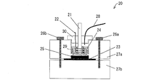
- Example 3 The performance evaluation of the positive electrode electrolyte when changing the molar ratio between manganese ions and nitrogen atoms contained in polyethyleneimine was performed by the following method using cyclic voltammetry. That is, in order to evaluate the performance of the positive electrode electrolyte, the electrode characteristics of the electrode immersed in the positive electrode electrolyte were measured (electrochemical measurement) using cyclic voltammetry having the following configuration as a measuring device. A schematic configuration of cyclic voltammetry (CV) will be described below with reference to FIG.
- CV cyclic voltammetry
- the cyclic voltammetry 20 includes an annular upper block 27a made of a fluororesin and a plate-like lower block 27b, and an O-ring 25 is interposed between the upper block 27a and the lower block 27b.
- the cell 29 is configured by sandwiching an electrode 23 made of glassy carbon (manufactured by Tokai Carbon Co., Ltd.) as a working electrode and fixing it with bolts 26a and 26b.
- the cell 29 is filled with the positive electrode electrolyte as the electrolyte 24 to be measured.
- the cyclic voltammetry 20 includes a reference electrode 21 made of a silver / silver chloride (saturated potassium chloride aqueous solution) electrode and a counter electrode 22 made of a platinum wire in the cell 29 so as to be immersed in the electrolyte solution 24 to be measured.
- a lid 30 covering the cell 29 is provided.
- the counter electrode 22 is arranged at a certain interval so as to be wound around the reference electrode 21.
- the lid 30 is formed with a hole through which the reference electrode 21, the counter electrode 22, and the tube 28 are passed.
- the tube 28 is configured to supply nitrogen gas above the measured electrolyte solution 24 in the cell 29 from a supply device (not shown). The supplied nitrogen gas blocks the measured electrolyte solution 24 from oxygen in the atmosphere. , To eliminate the effects of oxygen.
- the electrode characteristics of the electrode immersed in the positive electrode electrolyte were measured (electrochemical measurement), and the performance of the positive electrode electrolyte was evaluated.
- the cyclic voltammetry 20 is electrically connected to an electrochemical measurement system (HZ-5000; manufactured by Hokuto Denko Co., Ltd.), the measurement temperature is 20 ° C. or 60 ° C., and the electrode is in contact with the electrolyte solution 24 to be measured.
- HZ-5000 manufactured by Hokuto Denko Co., Ltd.
- a cathode electrolyte solution having a molar ratio of manganese ions to nitrogen atoms contained in polyethyleneimine of 1: 1 was prepared by the following method. That is, first, 0.02 mol (0.86 g) of polyethyleneimine was added and dissolved in 50 ml of distilled water. As the polyethyleneimine, polyethyleneimine having an average molecular weight of 600 (manufactured by Wako Pure Chemical Industries, Ltd.) was used.
- FIG. 4 is a graph when the measurement temperature is 20 ° C.
- FIG. 5 is a graph when the measurement temperature is 60 ° C.
- the horizontal axis represents the electrode potential (V VS Ag / AgCl)
- the vertical axis represents the response current value (mA). From the shape of the curve (cyclic voltammogram) drawn in the graph, the charge / discharge cycle characteristics (reversibility) of the positive electrode electrolyte a can be evaluated.
- the lower curve indicates the reduction wave and the upper curve indicates the oxidation wave.
- a reduction wave which is a lower curve
- the Mn (IV) -polyethyleneimine complex that is an oxidant present in the vicinity of the electrode 23 in the electrolyte solution to be measured 24 is reduced to a Mn (III) -polyethyleneimine complex that is a reductant.
- an oxidation wave that is the upper curve is drawn from the left side to the right side.
- the Mn (III) -polyethyleneimine complex which is a reductant present in the vicinity of the electrode 23 in the electrolyte solution 24 to be measured, is oxidized to a Mn (IV) -polyethyleneimine complex, which is an oxidant.
- the response current values in the reduction wave and the oxidation wave indicate weak currents generated by the oxidation-reduction reaction generated in the vicinity of the electrode 23 in the measured electrolyte solution 24, respectively.
- the redox potential of the redox reaction system of the Mn-polyethyleneimine complex can be determined from the average value of the peak potential (Ep) in both the reduced wave and the oxidized wave.
- a positive electrode electrolyte solution having a molar ratio of manganese ions to nitrogen atoms contained in polyethyleneimine of 1: 5 was prepared as the electrolyte solution to be measured by the following method. That is, first, 0.10 mol (4.30 g) of polyethyleneimine was added and dissolved in 50 ml of distilled water. As the polyethyleneimine, polyethyleneimine having an average molecular weight of 600 (manufactured by Wako Pure Chemical Industries, Ltd.) was used.
- FIGS. 6 is a graph when the measurement temperature is 20 ° C.
- FIG. 7 is a graph when the measurement temperature is 60 ° C.
- the positive electrode electrolyte a in which the molar ratio of manganese ions to nitrogen atoms contained in polyethyleneimine is 1: 1 is charge / discharge. It was found that the cycle characteristics (reversibility) were excellent and the reactivity of manganese ions was improved. Further, from the comparison between the graph of FIG. 5 and the graph of FIG. 7, at 60 ° C., the positive electrode electrolyte b in which the molar ratio of manganese ions to nitrogen atoms contained in polyethyleneimine is 1: 5 is charge / discharge. It was found that the cycle characteristics (reversibility) were excellent and the reactivity of manganese ions was improved.
- charge / discharge cycle characteristics can be obtained by changing the molar ratio of manganese ions to nitrogen atoms contained in polyethyleneimine in the positive electrode electrolyte according to the operating temperature (operating temperature) of the redox flow battery. It was found that a redox flow battery having excellent (reversibility) and further improved manganese ion reactivity can be provided.
- Example 4 The performance evaluation of the positive electrode electrolyte when the pH was changed was performed by the same method using the cyclic voltammetry similar to the cyclic voltammetry used in Example 3.
- a positive electrode electrolyte having a pH in the range of 1.28 to 6.80 was prepared by the following method. That is, first, 0.02 mol (0.86 g) of polyethyleneimine was added and dissolved in 50 ml of distilled water. As the polyethyleneimine, polyethyleneimine having an average molecular weight of 600 (manufactured by Wako Pure Chemical Industries, Ltd.) was used.
- aqueous solution is divided into four equal parts, and dilute sulfuric acid having a concentration of 2.5 mol / L is added dropwise to each aqueous solution to adjust the pH to 1.28, 3.01, 5.80, 6.80.
- the positive electrode electrolytes c-1 to c-4 were used.
- FIGS. 8 is a graph when the pH is 1.28 (positive electrode electrolyte c-1)
- FIG. 9 is a graph when the pH is 3.01 (positive electrode electrolyte c-2)
- FIG. Is is a graph when the pH is 5.80 (positive electrode electrolyte c-3)
- FIG. 11 is a graph when the pH is 6.80 (positive electrode electrolyte c-4).
- Example 5 The solubility of the Mn (II) -polyethyleneimine complex contained in the positive electrode electrolyte was confirmed by the following method.
- polyethyleneimine 0.02 mol (0.86 g) of polyethyleneimine was added and dissolved in 50 ml of distilled water.
- polyethyleneimine polyethyleneimine having an average molecular weight of 600 (manufactured by Wako Pure Chemical Industries, Ltd.) was used.
- the solubility of the Mn (II) -polyethyleneimine complex was 2.5 mol / L or more, and the concentration of the manganese-polyethyleneimine complex contained in the positive electrode electrolyte was 0.2 mol / L or more. It was found that the amount could be adjusted to 5 mol / L or less. As a result, it was found that the positive electrode electrolyte containing Mn (II) -polyethyleneimine complex can be suitably used for a redox flow battery.
- Example 3 A self-discharge test was performed by performing the same operation as in Example 1 except that the following aqueous solution was used as the positive electrode electrolyte.
- Example 4 A self-discharge test was performed by performing the same operation as in Example 1 except that the following aqueous solution was used as the positive electrode electrolyte.
- Example 7 A self-discharge test was performed by performing the same operation as in Example 1 except that the following aqueous solution was used as the positive electrode electrolyte.
- an aqueous solution having a concentration of Mn (II) -DL-malic acid complex of 0.2 mol / L was prepared.
- the self-discharge test was done by performing operation similar to Example 1 using the said aqueous solution as positive electrode electrolyte solution.
- Example 8 A self-discharge test was performed by performing the same operation as in Example 1 except that the following aqueous solution was used as the positive electrode electrolyte.
- Example 10 A self-discharge test was performed by performing the same operation as in Example 2 except that the following aqueous solutions were used as the negative electrode electrolyte and the positive electrode electrolyte.
- a negative electrode electrolyte was prepared by the following method. That is, first, 0.1 mol (6.0 g) of ethylenediamine was added to 70 ml of distilled water and dissolved. Subsequently, dilute sulfuric acid having a concentration of 2.5 mol / L was dropped into this aqueous solution to adjust the pH to 7. Thereafter, 0.02 mol (3.19 g) of CuSO 4 was added to the aqueous solution and dissolved, and then 0.05 mol (7.1 g) of Na 2 SO 4 (conductive salt) was added and dissolved. . Then, distilled water was added so that the total amount became 100 ml. Thereby, an aqueous solution having a molar ratio of copper and ethylenediamine of 1: 5 and a concentration of Cu (II) -ethylenediamine complex of 0.2 mol / L was prepared.
- a positive electrode electrolyte was prepared by the following method. That is, first, 0.1 mol (6.0 g) of ethylenediamine was added to 70 ml of distilled water and dissolved. Subsequently, dilute sulfuric acid having a concentration of 2.5 mol / L was dropped into this aqueous solution to adjust the pH to 7. Thereafter, 0.02 mol (3.38 g) of MnSO 4 .H 2 O was added to the aqueous solution and dissolved, and then 0.05 mol (7.1 g) of Na 2 SO 4 (conductive salt) was added. And dissolved. Then, distilled water was added so that the total amount became 100 ml.
- a charge / discharge test of a redox flow battery was performed under the same conditions as the charge / discharge test of Example 2.
- charging was performed at a constant current of 100 mA.
- the end-of-charge voltage was set to 2.0V.
- discharge was performed at a constant current of 100 mA.
- the discharge end voltage was set to 0.3V.
- Redox reactions of the positive electrode side is, the redox reaction of the negative electrode side "Cu (II)" Mn (II) - ethylenediamine complex ⁇ Mn (III) - - ethylenediamine complex + e "- ethylenediamine complex + e - ⁇ Cu (I ) -Ethylenediamine complex ".
- the “utilization ratio of the electrolytic solution” of the redox flow battery of Comparative Example 10 significantly decreased as the charge and discharge were repeated. That is, the redox flow type battery of Comparative Example 10 was inferior in “charge / discharge cycle characteristics (reversibility)” and “utilization rate of electrolytic solution” as compared with the redox flow type battery of Example 2. Therefore, it was found that the redox flow type battery of Comparative Example 10 did not have sufficient durability to be widely put into practical use as a power storage battery.
- the charge / discharge cell of the redox flow battery was disassembled, and the carbon felt (GFA5 manufactured by SGL) as the positive electrode and the negative electrode and the current collector plate were observed.
- the carbon felt GFA5 manufactured by SGL
- a large amount of manganese compound was observed on the positive electrode side, and a large amount of copper compound was observed on the negative electrode side.
- the redox flow type battery of Comparative Example 10 does not have sufficient durability to be widely put into practical use as a power storage battery. In the redox flow battery of Example 2, the above precipitation was hardly observed.
- polyethyleneimine polyethyleneimine with an average molecular weight of 600 (manufactured by Wako Pure Chemical Industries, Ltd.)
- ethylenediamine ethylenediamine
- flash point 248 ° C (Cleveland open type)
- acute toxicity oral LD50
- ethylenediamine is a dangerous class 4th class 2nd petroleum.
- the flash point is 34 ° C. (sealed)
- the acute toxicity (oral LD50) is 500 mg / kg. Therefore, it is clear that the redox flow type battery of Comparative Example 10 is inferior to the redox flow type battery of Example 2 in terms of handling as a dangerous substance and acute toxicity.
- a power storage battery that can prevent precipitation of a manganese compound, can prevent self-discharge of the power storage battery, and has improved manganese ion reactivity. be able to. Therefore, it is possible to provide a power storage battery having sufficient durability to be widely put into practical use by using a manganese redox material.
- the power storage battery according to the present invention can be widely used not only in power companies but also in various industries that require power storage.
- Redox flow battery power storage battery
- Charge / discharge cell battery container
- positive electrode side cell 2b negative electrode side cell
- positive electrode electrolyte tank 4
- negative electrode electrolyte tank 10 charging / discharging device 11
- diaphragm 12 current collector plate
- positive electrode 14
- current collector plate 15
- negative electrode 20
- cyclic voltammetry 21
- reference electrode 22
- counter electrode 23
- electrode (working electrode) 24
Abstract
Description
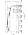
図1に示すように、本実施の形態に係るレドックスフロー型電池1は、充放電セル(電池容器)2、正極電解液タンク3および負極電解液タンク4を主として備えている。充放電セル2は、その内部が、例えばイオン交換膜からなる隔膜11によって正極側セル2aと負極側セル2bとに仕切られている。尚、充放電セル2には、レドックスフロー型電池1の能力(各種性能)を安定させるために、温度を一定に保つ温度調節装置が設けられていてもよい。 [Redox flow battery]
As shown in FIG. 1, the
上記負極電解液は、pHが好ましくは2~7の範囲内であり、より好ましくは4~6の範囲内であり、pH2~7の条件下において良好な酸化還元反応を行うことができる(イオンの状態で価数が変化する)負極側の活物質を含む水溶液であればよい。 [Negative Electrolyte]
The negative electrode electrolyte preferably has a pH in the range of 2 to 7, more preferably in the range of 4 to 6, and can perform a good redox reaction under conditions of
上記正極電解液は、pHが好ましくは2~7の範囲内であり、より好ましくは3~6の範囲内であり、pH2~7の条件下において良好な酸化還元反応を行うことができる(イオンの状態で価数が変化する)正極側の活物質を含む水溶液、つまり、正極側の活物質としてマンガンレドックス系物質を含むと共に、ポリエチレンイミンを含む水溶液であればよい。 (Cathode electrolyte)
The positive electrode electrolyte preferably has a pH in the range of 2 to 7, more preferably in the range of 3 to 6, and can perform a good redox reaction under the conditions of
レドックスフロー型電池の起電力は、高い方がより好ましい。本実施の形態に係るレドックスフロー型電池は、正極電解液がMn-ポリエチレンイミン錯体を含む水溶液であり、Mnは起電力が比較的高いため、1.0V以上の高出力のレドックスフロー型電池とすることができる。 [Performance of redox flow battery]
A higher electromotive force of the redox flow battery is more preferable. The redox flow battery according to the present embodiment is an aqueous solution in which the positive electrode electrolyte contains a Mn-polyethyleneimine complex, and Mn has a relatively high electromotive force. can do.
レドックスフロー型電池の性能評価を下記方法にて行った。 [Example 1]
The performance evaluation of the redox flow battery was performed by the following method.
負極電解液を、下記方法によって調製した。即ち、先ず、蒸留水50mlに、0.02モル(0.86g)のポリエチレンイミンを加えて溶解させた。当該ポリエチレンイミンとして、平均分子量が600のポリエチレンイミン(和光純薬工業株式会社製)を用いた。 [Example 2]
A negative electrode electrolyte was prepared by the following method. That is, first, 0.02 mol (0.86 g) of polyethyleneimine was added and dissolved in 50 ml of distilled water. As the polyethyleneimine, polyethyleneimine having an average molecular weight of 600 (manufactured by Wako Pure Chemical Industries, Ltd.) was used.
マンガンイオンとポリエチレンイミンに含まれる窒素原子とのモル比を変更したときの正極電解液の性能評価を、サイクリックボルタンメトリーを用いて下記方法にて行った。即ち、正極電解液の性能を評価するために、測定装置として下記構成のサイクリックボルタンメトリーを用いて、正極電解液に浸漬した電極の電極特性を測定(電気化学測定)した。サイクリックボルタンメトリー(CV)の概略の構成を、図12に基づいて説明すれば、以下の通りである。 Example 3
The performance evaluation of the positive electrode electrolyte when changing the molar ratio between manganese ions and nitrogen atoms contained in polyethyleneimine was performed by the following method using cyclic voltammetry. That is, in order to evaluate the performance of the positive electrode electrolyte, the electrode characteristics of the electrode immersed in the positive electrode electrolyte were measured (electrochemical measurement) using cyclic voltammetry having the following configuration as a measuring device. A schematic configuration of cyclic voltammetry (CV) will be described below with reference to FIG.
pHを変更したときの正極電解液の性能評価を、実施例3で用いたサイクリックボルタンメトリーと同様のサイクリックボルタンメトリーを用いて、同様の方法にて行った。 Example 4
The performance evaluation of the positive electrode electrolyte when the pH was changed was performed by the same method using the cyclic voltammetry similar to the cyclic voltammetry used in Example 3.
正極電解液に含まれるMn(II)-ポリエチレンイミン錯体の溶解度を、下記方法にて確認した。 Example 5
The solubility of the Mn (II) -polyethyleneimine complex contained in the positive electrode electrolyte was confirmed by the following method.
導電塩としてNa2SO4の替わりに0.10モル(5.85g)のNaClを加えた以外は、実施例1と同様の操作を行うことにより、Mn(II)-ポリエチレンイミン錯体の濃度が0.2モル/Lである水溶液を調製した。 [Comparative Example 1]
By performing the same operation as in Example 1 except that 0.10 mol (5.85 g) NaCl was added instead of Na 2 SO 4 as the conductive salt, the concentration of Mn (II) -polyethyleneimine complex was increased. An aqueous solution that was 0.2 mol / L was prepared.
自己放電試験において充電後に、充放電セル並びに正極電解液タンクおよび負極電解液タンクを大気中に暴露した以外は、実施例1と同様の操作を行うことにより、自己放電試験を行った。その結果、レドックスフロー型電池は、正極電解液の液面に接するガスに酸素が多く含まれている(大気では約20%)と、自己放電する(自己放電が非常に速い)ことが判った。 [Comparative Example 2]
In the self-discharge test, a self-discharge test was performed by performing the same operation as in Example 1 except that the charge / discharge cell, the positive electrode electrolyte tank, and the negative electrode electrolyte tank were exposed to the atmosphere after charging. As a result, it was found that the redox flow battery self-discharges (self-discharge is very fast) when the gas in contact with the liquid surface of the positive electrode electrolyte contains a large amount of oxygen (about 20% in the atmosphere). .
正極電解液として下記水溶液を用いた以外は、実施例1と同様の操作を行うことにより、自己放電試験を行った。 [Comparative Example 3]
A self-discharge test was performed by performing the same operation as in Example 1 except that the following aqueous solution was used as the positive electrode electrolyte.
正極電解液として下記水溶液を用いた以外は、実施例1と同様の操作を行うことにより、自己放電試験を行った。 [Comparative Example 4]
A self-discharge test was performed by performing the same operation as in Example 1 except that the following aqueous solution was used as the positive electrode electrolyte.
先ず、蒸留水70mlに、0.02モル(2.96g)のマロン酸二ナトリウムを加えて溶解させた後、濃度が2.5モル/Lの希硫酸を滴下してpHを7に調節した。続いて、上記水溶液に、0.02モル(3.38g)のMnSO4・H2Oを加えて溶解させた後、0.05モル(7.1g)のNa2SO4を加えて溶解させた。次いで、全量が100mlになるように蒸留水を加えた。これにより、Mn(II)-マロン酸錯体の濃度が0.2モル/Lである水溶液を調製しようとしたが、マンガン化合物が直ちに析出することが判った。従って、ポリエチレンイミンの替わりにポリカルボン酸であるマロン酸を用いて、Mn(II)-マロン酸錯体を充分な濃度で含む正極電解液を調製することができないことが判った。 [Comparative Example 5]
First, 0.02 mol (2.96 g) of disodium malonate was added to 70 ml of distilled water and dissolved, and then dilute sulfuric acid having a concentration of 2.5 mol / L was added dropwise to adjust the pH to 7. . Subsequently, 0.02 mol (3.38 g) of MnSO 4 .H 2 O was added to the aqueous solution and dissolved, and then 0.05 mol (7.1 g) of Na 2 SO 4 was added and dissolved. It was. Then, distilled water was added so that the total amount became 100 ml. Thus, an attempt was made to prepare an aqueous solution having a Mn (II) -malonic acid complex concentration of 0.2 mol / L, but it was found that the manganese compound was immediately deposited. Therefore, it was found that a positive electrode electrolyte containing a sufficient concentration of Mn (II) -malonic acid complex cannot be prepared by using malonic acid, which is a polycarboxylic acid, instead of polyethyleneimine.
先ず、蒸留水70mlに、0.02モル(3.24g)のコハク酸二ナトリウムを加えて溶解させた後、濃度が2.5モル/Lの希硫酸を滴下してpHを7に調節した。続いて、上記水溶液に、0.02モル(3.38g)のMnSO4・H2Oを加えて溶解させた後、0.05モル(7.1g)のNa2SO4を加えて溶解させた。次いで、全量が100mlになるように蒸留水を加えた。これにより、Mn(II)-コハク酸錯体の濃度が0.2モル/Lである水溶液を調製しようとしたが、マンガン化合物が直ちに析出することが判った。従って、ポリエチレンイミンの替わりにポリカルボン酸であるコハク酸を用いて、Mn(II)-コハク酸錯体を充分な濃度で含む正極電解液を調製することができないことが判った。 [Comparative Example 6]
First, 0.02 mol (3.24 g) of disodium succinate was added to 70 ml of distilled water and dissolved, and then dilute sulfuric acid having a concentration of 2.5 mol / L was added dropwise to adjust the pH to 7. . Subsequently, 0.02 mol (3.38 g) of MnSO 4 .H 2 O was added to the aqueous solution and dissolved, and then 0.05 mol (7.1 g) of Na 2 SO 4 was added and dissolved. It was. Then, distilled water was added so that the total amount became 100 ml. Thus, an attempt was made to prepare an aqueous solution having a concentration of Mn (II) -succinic acid complex of 0.2 mol / L, but it was found that the manganese compound was immediately deposited. Therefore, it was found that a positive electrode electrolyte containing a sufficient concentration of Mn (II) -succinic acid complex cannot be prepared using succinic acid, which is a polycarboxylic acid, instead of polyethyleneimine.
正極電解液として下記水溶液を用いた以外は、実施例1と同様の操作を行うことにより、自己放電試験を行った。 [Comparative Example 7]
A self-discharge test was performed by performing the same operation as in Example 1 except that the following aqueous solution was used as the positive electrode electrolyte.
正極電解液として下記水溶液を用いた以外は、実施例1と同様の操作を行うことにより、自己放電試験を行った。 [Comparative Example 8]
A self-discharge test was performed by performing the same operation as in Example 1 except that the following aqueous solution was used as the positive electrode electrolyte.
先ず、蒸留水70mlに、0.02モル(1.2g)のエチレンジアミンを加えて溶解させた後、濃度が2.5モル/Lの希硫酸を滴下してpHを7に調節した。続いて、上記水溶液に、0.02モル(3.38g)のMnSO4・H2Oを加えて溶解させた後、0.05モル(7.1g)のNa2SO4を加えて溶解させた。次いで、全量が100mlになるように蒸留水を加えた。これにより、マンガンとエチレンジアミンとのモル比が1:1の、Mn(II)-エチレンジアミン錯体の濃度が0.2モル/Lである水溶液を調製しようとしたが、マンガン化合物が直ちに析出することが判った。従って、ポリエチレンイミンの替わりにエチレンジアミンを用いて、Mn(II)-エチレンジアミン錯体を充分な濃度で含む正極電解液を調製することができないことが判った。 [Comparative Example 9]
First, 0.02 mol (1.2 g) of ethylenediamine was added to 70 ml of distilled water and dissolved, and then diluted sulfuric acid having a concentration of 2.5 mol / L was added dropwise to adjust the pH to 7. Subsequently, 0.02 mol (3.38 g) of MnSO 4 .H 2 O was added to the aqueous solution and dissolved, and then 0.05 mol (7.1 g) of Na 2 SO 4 was added and dissolved. It was. Then, distilled water was added so that the total amount became 100 ml. Thereby, an attempt was made to prepare an aqueous solution in which the molar ratio of manganese to ethylenediamine was 1: 1 and the concentration of Mn (II) -ethylenediamine complex was 0.2 mol / L. understood. Therefore, it was found that a positive electrode electrolyte containing a sufficient concentration of Mn (II) -ethylenediamine complex cannot be prepared by using ethylenediamine instead of polyethyleneimine.
負極電解液および正極電解液として下記水溶液を用いた以外は、実施例2と同様の操作を行うことにより、自己放電試験を行った。 [Comparative Example 10]
A self-discharge test was performed by performing the same operation as in Example 2 except that the following aqueous solutions were used as the negative electrode electrolyte and the positive electrode electrolyte.
2 充放電セル(電池容器)
2a 正極側セル
2b 負極側セル
3 正極電解液タンク
4 負極電解液タンク
10 充放電装置
11 隔膜
12 集電板
13 正極
14 集電板
15 負極
20 サイクリックボルタンメトリー
21 参照電極
22 対極
23 電極(作用電極)
24 被測定電解液 1 Redox flow battery (power storage battery)
2 Charge / discharge cell (battery container)
2a positive
24 Electrolytic solution to be measured
Claims (11)
- レドックス型の電力貯蔵電池において、
正極電解液が、正極側の活物質としてマンガンレドックス系物質を含むと共に、ポリエチレンイミンを含む水溶液であることを特徴とする電力貯蔵電池。 In redox type power storage battery,
A power storage battery, wherein the positive electrode electrolyte solution is an aqueous solution containing a polyethylene redine material and a manganese redox-based material as an active material on the positive electrode side. - マンガンイオンと、ポリエチレンイミンに含まれる窒素原子とのモル比が、1:1~1:5の範囲内であることを特徴とする請求項1に記載の電力貯蔵電池。 The power storage battery according to claim 1, wherein the molar ratio of manganese ions to nitrogen atoms contained in polyethyleneimine is in the range of 1: 1 to 1: 5.
- 上記正極電解液に含まれるマンガン-ポリエチレンイミン錯体の濃度が、0.2モル/L以上、2.5モル/L以下であることを特徴とする請求項1に記載の電力貯蔵電池。 The power storage battery according to claim 1, wherein the concentration of the manganese-polyethyleneimine complex contained in the positive electrode electrolyte is 0.2 mol / L or more and 2.5 mol / L or less.
- 上記正極電解液のpHが2~7の範囲内であることを特徴とする請求項1に記載の電力貯蔵電池。 The power storage battery according to claim 1, wherein the pH of the positive electrode electrolyte is in the range of 2-7.
- 上記マンガンレドックス系物質が硫酸マンガンであることを特徴とする請求項1に記載の電力貯蔵電池。 The power storage battery according to claim 1, wherein the manganese redox-based substance is manganese sulfate.
- 上記正極電解液が電解酸化されていることを特徴とする請求項1に記載の電力貯蔵電池。 The power storage battery according to claim 1, wherein the positive electrode electrolyte is electrolytically oxidized.
- 上記正極電解液が大気中の酸素と遮断されていることを特徴とする請求項1に記載の電力貯蔵電池。 The power storage battery according to claim 1, wherein the positive electrode electrolyte is shielded from oxygen in the atmosphere.
- 負極電解液が、負極側の活物質として鉄レドックス系物質を含む水溶液であることを特徴とする電力貯蔵電池。 A power storage battery, wherein the negative electrode electrolyte is an aqueous solution containing an iron redox-based material as an active material on the negative electrode side.
- 上記負極電解液が、鉄-ジエチレントリアミン五酢酸錯体を含む水溶液であることを特徴とする請求項8に記載の電力貯蔵電池。 The power storage battery according to claim 8, wherein the negative electrode electrolyte is an aqueous solution containing an iron-diethylenetriaminepentaacetic acid complex.
- 上記負極電解液が電解酸化されていることを特徴とする請求項8に記載の電力貯蔵電池。 The power storage battery according to claim 8, wherein the negative electrode electrolyte is electrolytically oxidized.
- レドックスフロー型電池であることを特徴とする請求項1に記載の電力貯蔵電池。 The power storage battery according to claim 1, which is a redox flow battery.
Priority Applications (6)
| Application Number | Priority Date | Filing Date | Title |
|---|---|---|---|
| PCT/JP2012/061546 WO2013164879A1 (en) | 2012-05-01 | 2012-05-01 | Energy storage battery |
| CN201280067242.1A CN104054203B (en) | 2012-05-01 | 2012-05-01 | Energy storage battery |
| IN8835DEN2014 IN2014DN08835A (en) | 2012-05-01 | 2012-05-01 | |
| EP12876002.2A EP2846389B1 (en) | 2012-05-01 | 2012-05-01 | Energy storage battery |
| JP2014513318A JP5768933B2 (en) | 2012-05-01 | 2012-05-01 | Power storage battery |
| US14/388,246 US9577283B2 (en) | 2012-05-01 | 2012-05-01 | Energy storage battery |
Applications Claiming Priority (1)
| Application Number | Priority Date | Filing Date | Title |
|---|---|---|---|
| PCT/JP2012/061546 WO2013164879A1 (en) | 2012-05-01 | 2012-05-01 | Energy storage battery |
Publications (1)
| Publication Number | Publication Date |
|---|---|
| WO2013164879A1 true WO2013164879A1 (en) | 2013-11-07 |
Family
ID=49514289
Family Applications (1)
| Application Number | Title | Priority Date | Filing Date |
|---|---|---|---|
| PCT/JP2012/061546 WO2013164879A1 (en) | 2012-05-01 | 2012-05-01 | Energy storage battery |
Country Status (6)
| Country | Link |
|---|---|
| US (1) | US9577283B2 (en) |
| EP (1) | EP2846389B1 (en) |
| JP (1) | JP5768933B2 (en) |
| CN (1) | CN104054203B (en) |
| IN (1) | IN2014DN08835A (en) |
| WO (1) | WO2013164879A1 (en) |
Cited By (4)
| Publication number | Priority date | Publication date | Assignee | Title |
|---|---|---|---|---|
| JP2018533818A (en) * | 2015-10-30 | 2018-11-15 | マサチューセッツ インスティテュート オブ テクノロジー | Air Breathing Aqueous Sulfur Rechargeable Battery |
| WO2018235419A1 (en) * | 2017-06-21 | 2018-12-27 | 住友電気工業株式会社 | Redox flow battery |
| CN114079111A (en) * | 2020-08-11 | 2022-02-22 | 北京好风光储能技术有限公司 | Large-scale vertical energy storage battery and energy storage container |
| WO2023149224A1 (en) * | 2022-02-01 | 2023-08-10 | 国立研究開発法人産業技術総合研究所 | Method for regenerating electrolyte solution for redox flow batteries and method for operating redox flow battery |
Families Citing this family (5)
| Publication number | Priority date | Publication date | Assignee | Title |
|---|---|---|---|---|
| GB201522003D0 (en) | 2015-12-14 | 2016-01-27 | Imp Innovations Ltd | Regenerative fuel cells |
| KR102006820B1 (en) * | 2016-11-25 | 2019-08-02 | 울산과학기술원 | Electrolyte composition and microbial fuel cells comprising the same |
| CN111313128B (en) * | 2018-12-11 | 2021-06-22 | 中国科学院大连化学物理研究所 | Aluminum-air battery for communication base station and control method |
| EP3726633A1 (en) * | 2019-04-16 | 2020-10-21 | Universität Innsbruck | Redox flow battery |
| US11664518B2 (en) * | 2021-05-21 | 2023-05-30 | Raytheon Technologies Corporation | Alkaline manganese redox flow battery with inhibitor |
Citations (5)
| Publication number | Priority date | Publication date | Assignee | Title |
|---|---|---|---|---|
| JPS5642970A (en) | 1979-09-14 | 1981-04-21 | Agency Of Ind Science & Technol | Redox battery |
| JPS579073A (en) | 1980-06-17 | 1982-01-18 | Agency Of Ind Science & Technol | Bedox battery |
| JPH11158271A (en) * | 1997-11-26 | 1999-06-15 | Kagaku Gijutsu Senryaku Suishin Kiko | Polyethyleneimine and its production |
| JP2009231230A (en) | 2008-03-25 | 2009-10-08 | Kurita Water Ind Ltd | Microbial power generation method and device |
| WO2011111254A1 (en) * | 2010-03-12 | 2011-09-15 | 住友電気工業株式会社 | Redox flow battery |
Family Cites Families (8)
| Publication number | Priority date | Publication date | Assignee | Title |
|---|---|---|---|---|
| US4362791A (en) | 1980-06-17 | 1982-12-07 | Agency Of Industrial Science & Technology | Redox battery |
| JPS58133788A (en) * | 1982-02-01 | 1983-08-09 | Semiconductor Energy Lab Co Ltd | Electrolyte solution |
| DE69630298T2 (en) | 1995-05-03 | 2004-09-02 | Pinnacle Vrb Limited, Melbourne | METHOD FOR PRODUCING A VANADIUM ELECTROLYTE FOR WHOLE VANADIUM REDOX CELLS AND BATTERIES WITH HIGH ENERGY DENSITY |
| US20020122980A1 (en) * | 1998-05-19 | 2002-09-05 | Fleischer Niles A. | Electrochemical cell with a non-liquid electrolyte |
| CN100459269C (en) * | 2006-03-31 | 2009-02-04 | 中国科学院大连化学物理研究所 | Iron composite/halogen electrochemical system for flow electric storage |
| GB0614337D0 (en) * | 2006-07-19 | 2006-08-30 | Acal Energy Ltd | Fuel Cells |
| US7820321B2 (en) | 2008-07-07 | 2010-10-26 | Enervault Corporation | Redox flow battery system for distributed energy storage |
| KR101638595B1 (en) | 2010-01-29 | 2016-07-12 | 삼성전자주식회사 | Redox flow battery |
-
2012
- 2012-05-01 WO PCT/JP2012/061546 patent/WO2013164879A1/en active Application Filing
- 2012-05-01 JP JP2014513318A patent/JP5768933B2/en active Active
- 2012-05-01 CN CN201280067242.1A patent/CN104054203B/en not_active Expired - Fee Related
- 2012-05-01 US US14/388,246 patent/US9577283B2/en active Active
- 2012-05-01 IN IN8835DEN2014 patent/IN2014DN08835A/en unknown
- 2012-05-01 EP EP12876002.2A patent/EP2846389B1/en not_active Not-in-force
Patent Citations (5)
| Publication number | Priority date | Publication date | Assignee | Title |
|---|---|---|---|---|
| JPS5642970A (en) | 1979-09-14 | 1981-04-21 | Agency Of Ind Science & Technol | Redox battery |
| JPS579073A (en) | 1980-06-17 | 1982-01-18 | Agency Of Ind Science & Technol | Bedox battery |
| JPH11158271A (en) * | 1997-11-26 | 1999-06-15 | Kagaku Gijutsu Senryaku Suishin Kiko | Polyethyleneimine and its production |
| JP2009231230A (en) | 2008-03-25 | 2009-10-08 | Kurita Water Ind Ltd | Microbial power generation method and device |
| WO2011111254A1 (en) * | 2010-03-12 | 2011-09-15 | 住友電気工業株式会社 | Redox flow battery |
Non-Patent Citations (5)
| Title |
|---|
| "Ethylenediamine (Serial No.: JW050093) Product Safety Data Sheet (MSDS", MSDS/REAGENTS HOMEPAGE, 1 September 2001 (2001-09-01), Retrieved from the Internet <URL:http://www.wako-chem.co.jp/siyaku/msds.htm), Wako Pure Chemical Industries, Ltd.> |
| "Polyethyleneimine (Serial No.: JW161783) Product Safety Data Sheet (MSDS", MSDS/REAGENTS HOMEPAGE, 28 July 2004 (2004-07-28), Retrieved from the Internet <URL:http://www.wako-chem.co.jp/siyaku/msds.htm), Wako Pure Chemical Industries, Ltd.> |
| IWANAMI: "Dictionary of Physics and Chemistry", 20 February 1998, IWANAMI SHOTEN, pages: 223 |
| See also references of EP2846389A4 * |
| TAKASHI SHIRAKASHI: "Abstract of PhD dissertation for Graduate School of Science (doctoral course", 25 March 1969, article "Study of Equilibrium and Rate on Ethylenediaminetetraacetatomanganate(III) Complex" |
Cited By (8)
| Publication number | Priority date | Publication date | Assignee | Title |
|---|---|---|---|---|
| JP2018533818A (en) * | 2015-10-30 | 2018-11-15 | マサチューセッツ インスティテュート オブ テクノロジー | Air Breathing Aqueous Sulfur Rechargeable Battery |
| US10992003B2 (en) | 2015-10-30 | 2021-04-27 | Massachusetts Institute Of Technology | Air-breathing aqueous sulfur rechargeable batteries |
| WO2018235419A1 (en) * | 2017-06-21 | 2018-12-27 | 住友電気工業株式会社 | Redox flow battery |
| JPWO2018235419A1 (en) * | 2017-06-21 | 2020-04-23 | 住友電気工業株式会社 | Redox flow battery |
| JP7001094B2 (en) | 2017-06-21 | 2022-01-19 | 住友電気工業株式会社 | Redox flow battery |
| CN114079111A (en) * | 2020-08-11 | 2022-02-22 | 北京好风光储能技术有限公司 | Large-scale vertical energy storage battery and energy storage container |
| CN114079111B (en) * | 2020-08-11 | 2023-11-14 | 好风光储能技术(成都)有限公司 | Large vertical energy storage battery and energy storage container |
| WO2023149224A1 (en) * | 2022-02-01 | 2023-08-10 | 国立研究開発法人産業技術総合研究所 | Method for regenerating electrolyte solution for redox flow batteries and method for operating redox flow battery |
Also Published As
| Publication number | Publication date |
|---|---|
| US9577283B2 (en) | 2017-02-21 |
| IN2014DN08835A (en) | 2015-05-22 |
| EP2846389B1 (en) | 2017-02-22 |
| US20150214565A1 (en) | 2015-07-30 |
| JPWO2013164879A1 (en) | 2015-12-24 |
| CN104054203B (en) | 2017-03-22 |
| CN104054203A (en) | 2014-09-17 |
| EP2846389A1 (en) | 2015-03-11 |
| JP5768933B2 (en) | 2015-08-26 |
| EP2846389A4 (en) | 2015-12-16 |
Similar Documents
| Publication | Publication Date | Title |
|---|---|---|
| JP5768933B2 (en) | Power storage battery | |
| WO2012117594A1 (en) | Power storage battery | |
| JP2019012691A (en) | Aqueous redox flow battery containing metal ligand coordination compound | |
| WO2014207923A1 (en) | Redox flow battery | |
| JPH0864223A (en) | Electrolyte for vanadium redox flow type battery | |
| Xie et al. | High performance of zinc-ferrum redox flow battery with Ac−/HAc buffer solution | |
| Noh et al. | Organometallic redox flow batteries using iron triethanolamine and cobalt triethanolamine complexes | |
| CN111326779A (en) | Method for improving transmission performance of eutectic solvent electrolyte flow battery and flow battery | |
| JP2023527872A (en) | FE-CR Redox Flow Battery System and Method of Using the System | |
| JP5874833B2 (en) | Power storage battery and manufacturing method thereof | |
| JP6065351B2 (en) | Power storage battery | |
| CN110100343A (en) | Redox flow batteries | |
| Bryans et al. | Synthesis and characterisation of novel additives for use in the hybrid ZnBr2 flow battery | |
| US20220181666A1 (en) | Electrochemical storage devices comprising chelated metals | |
| JP6065348B2 (en) | Power storage battery and manufacturing method thereof | |
| JP6065349B2 (en) | Power storage battery and manufacturing method thereof | |
| WO2013118278A1 (en) | Power storage battery | |
| US20230051932A1 (en) | Iron complexes with phosphonate-based ligands as rfb anolyte materials | |
| Cao et al. | Vanadium-Mediated High Areal Capacity Zinc–Manganese Redox Flow Battery | |
| Artault et al. | Azoniafluorenones: A New Family of Two-electron Storage Electrolytes for Sustainable Near-Neutral pH Aqueous Organic Flow Battery | |
| Pritchard | Low-Cost and Sustainable All-Iron Redox Flow Battery Energy Storage | |
| WO2016207959A1 (en) | Redox flow battery |
Legal Events
| Date | Code | Title | Description |
|---|---|---|---|
| 121 | Ep: the epo has been informed by wipo that ep was designated in this application |
Ref document number: 12876002 Country of ref document: EP Kind code of ref document: A1 |
|
| ENP | Entry into the national phase |
Ref document number: 2014513318 Country of ref document: JP Kind code of ref document: A |
|
| WWE | Wipo information: entry into national phase |
Ref document number: 14388246 Country of ref document: US |
|
| REEP | Request for entry into the european phase |
Ref document number: 2012876002 Country of ref document: EP |
|
| WWE | Wipo information: entry into national phase |
Ref document number: 2012876002 Country of ref document: EP |
|
| NENP | Non-entry into the national phase |
Ref country code: DE |