WO2013161699A1 - Ozone water generating device - Google Patents
Ozone water generating device Download PDFInfo
- Publication number
- WO2013161699A1 WO2013161699A1 PCT/JP2013/061617 JP2013061617W WO2013161699A1 WO 2013161699 A1 WO2013161699 A1 WO 2013161699A1 JP 2013061617 W JP2013061617 W JP 2013061617W WO 2013161699 A1 WO2013161699 A1 WO 2013161699A1
- Authority
- WO
- WIPO (PCT)
- Prior art keywords
- anode
- housing
- cathode
- catalyst electrode
- ozone water
- Prior art date
Links
Images


Classifications
-
- C—CHEMISTRY; METALLURGY
- C25—ELECTROLYTIC OR ELECTROPHORETIC PROCESSES; APPARATUS THEREFOR
- C25B—ELECTROLYTIC OR ELECTROPHORETIC PROCESSES FOR THE PRODUCTION OF COMPOUNDS OR NON-METALS; APPARATUS THEREFOR
- C25B13/00—Diaphragms; Spacing elements
- C25B13/04—Diaphragms; Spacing elements characterised by the material
-
- C—CHEMISTRY; METALLURGY
- C02—TREATMENT OF WATER, WASTE WATER, SEWAGE, OR SLUDGE
- C02F—TREATMENT OF WATER, WASTE WATER, SEWAGE, OR SLUDGE
- C02F1/00—Treatment of water, waste water, or sewage
- C02F1/46—Treatment of water, waste water, or sewage by electrochemical methods
- C02F1/461—Treatment of water, waste water, or sewage by electrochemical methods by electrolysis
- C02F1/467—Treatment of water, waste water, or sewage by electrochemical methods by electrolysis by electrochemical disinfection; by electrooxydation or by electroreduction
- C02F1/4672—Treatment of water, waste water, or sewage by electrochemical methods by electrolysis by electrochemical disinfection; by electrooxydation or by electroreduction by electrooxydation
-
- C—CHEMISTRY; METALLURGY
- C25—ELECTROLYTIC OR ELECTROPHORETIC PROCESSES; APPARATUS THEREFOR
- C25B—ELECTROLYTIC OR ELECTROPHORETIC PROCESSES FOR THE PRODUCTION OF COMPOUNDS OR NON-METALS; APPARATUS THEREFOR
- C25B1/00—Electrolytic production of inorganic compounds or non-metals
- C25B1/01—Products
- C25B1/13—Ozone
-
- C—CHEMISTRY; METALLURGY
- C25—ELECTROLYTIC OR ELECTROPHORETIC PROCESSES; APPARATUS THEREFOR
- C25B—ELECTROLYTIC OR ELECTROPHORETIC PROCESSES FOR THE PRODUCTION OF COMPOUNDS OR NON-METALS; APPARATUS THEREFOR
- C25B9/00—Cells or assemblies of cells; Constructional parts of cells; Assemblies of constructional parts, e.g. electrode-diaphragm assemblies; Process-related cell features
- C25B9/17—Cells comprising dimensionally-stable non-movable electrodes; Assemblies of constructional parts thereof
- C25B9/19—Cells comprising dimensionally-stable non-movable electrodes; Assemblies of constructional parts thereof with diaphragms
-
- C—CHEMISTRY; METALLURGY
- C02—TREATMENT OF WATER, WASTE WATER, SEWAGE, OR SLUDGE
- C02F—TREATMENT OF WATER, WASTE WATER, SEWAGE, OR SLUDGE
- C02F1/00—Treatment of water, waste water, or sewage
- C02F1/46—Treatment of water, waste water, or sewage by electrochemical methods
- C02F1/461—Treatment of water, waste water, or sewage by electrochemical methods by electrolysis
- C02F1/46104—Devices therefor; Their operating or servicing
- C02F1/46109—Electrodes
- C02F2001/46133—Electrodes characterised by the material
- C02F2001/46138—Electrodes comprising a substrate and a coating
- C02F2001/46142—Catalytic coating
-
- C—CHEMISTRY; METALLURGY
- C02—TREATMENT OF WATER, WASTE WATER, SEWAGE, OR SLUDGE
- C02F—TREATMENT OF WATER, WASTE WATER, SEWAGE, OR SLUDGE
- C02F2201/00—Apparatus for treatment of water, waste water or sewage
- C02F2201/46—Apparatus for electrochemical processes
- C02F2201/461—Electrolysis apparatus
- C02F2201/46105—Details relating to the electrolytic devices
- C02F2201/46115—Electrolytic cell with membranes or diaphragms
-
- C—CHEMISTRY; METALLURGY
- C02—TREATMENT OF WATER, WASTE WATER, SEWAGE, OR SLUDGE
- C02F—TREATMENT OF WATER, WASTE WATER, SEWAGE, OR SLUDGE
- C02F2201/00—Apparatus for treatment of water, waste water or sewage
- C02F2201/46—Apparatus for electrochemical processes
- C02F2201/461—Electrolysis apparatus
- C02F2201/46105—Details relating to the electrolytic devices
- C02F2201/4612—Controlling or monitoring
- C02F2201/46125—Electrical variables
- C02F2201/4614—Current
-
- C—CHEMISTRY; METALLURGY
- C02—TREATMENT OF WATER, WASTE WATER, SEWAGE, OR SLUDGE
- C02F—TREATMENT OF WATER, WASTE WATER, SEWAGE, OR SLUDGE
- C02F2201/00—Apparatus for treatment of water, waste water or sewage
- C02F2201/46—Apparatus for electrochemical processes
- C02F2201/461—Electrolysis apparatus
- C02F2201/46105—Details relating to the electrolytic devices
- C02F2201/4616—Power supply
- C02F2201/4617—DC only
-
- C—CHEMISTRY; METALLURGY
- C02—TREATMENT OF WATER, WASTE WATER, SEWAGE, OR SLUDGE
- C02F—TREATMENT OF WATER, WASTE WATER, SEWAGE, OR SLUDGE
- C02F2209/00—Controlling or monitoring parameters in water treatment
- C02F2209/23—O3
Landscapes
- Chemical & Material Sciences (AREA)
- Organic Chemistry (AREA)
- Chemical Kinetics & Catalysis (AREA)
- Electrochemistry (AREA)
- Engineering & Computer Science (AREA)
- Metallurgy (AREA)
- Materials Engineering (AREA)
- Inorganic Chemistry (AREA)
- Life Sciences & Earth Sciences (AREA)
- Water Supply & Treatment (AREA)
- Environmental & Geological Engineering (AREA)
- Hydrology & Water Resources (AREA)
- General Chemical & Material Sciences (AREA)
- Electrolytic Production Of Non-Metals, Compounds, Apparatuses Therefor (AREA)
- Water Treatment By Electricity Or Magnetism (AREA)
- Oxygen, Ozone, And Oxides In General (AREA)
Abstract
An ozone water generating device provided with a first housing (1), a second housing (2), and a catalyst electrode (3), in which the catalyst electrode (3) is provided with a positive electrode (32), a positive ion exchange membrane (31), and a negative electrode (33) in this order from the first housing side, and ozone water is generated by supplying raw-material water to the catalyst electrode (3) and applying a direct-current voltage across a positive electrode (32) and a negative electrode (33), wherein a positive-electrode supply channel and a discharge channel are provided to the first housing (1), a negative-electrode supply channel and a discharge channel are provided to the second housing, a cushioning material (15) is provided between the positive electrode (32) and the first housing (1), and pressing members (41, 42) for directly pressing the catalyst electrode (3) are provided to the first housing (1) so as to penetrate through the first housing (1). The pressing members (41, 42) are disposed in a position of pressing on at least a center part of the catalyst electrode (3), and the positive electrode (32), the positive ion exchange membrane (31), and the negative electrode (33) are pressure welded by the pressing of the pressing members (41, 42).
Description
本発明は、オゾン水生成装置に関する。
The present invention relates to an ozone water generator.
近年、オゾン水は食品の殺菌や悪臭ガスの脱臭などの用途に広範に使用されており、さらに医療や介護の分野で、数多い知見例が発表され始めている。また、半導体製造領域においても、超微細構造に対するオゾン酸化の特徴が認められ、オゾン水の使用が必須とされている。
このようなオゾン水の製法として、陽イオン交換膜の一方の面に陽極を圧接させ、他方の面に陰極を圧接してなる触媒電極の電解面に原料水を直接接触させて、水の電気分解によりオゾン水を生成させる直接電解法を利用したものが知られている(例えば、特許文献1参照)。
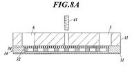
ところで、陽極または陰極を陽イオン交換膜に圧接させるために、例えば、図8A、図8Bに示すように、陽極32及びグレーチング34上に筐体11を重ね合わせ、この筐体11を貫通させて押しネジ41をねじ込み、陽極32を陽イオン交換膜31に押圧する方法が知られている。図8では、筐体11を貫通して、陽イオン交換膜31に通じる原料水供給路5及び生成されたオゾン水が排出されるオゾン水排出路6が形成されている。そして、原料水供給路5から供給された原料水は、陽極32及び陽イオン交換膜31に接触して、生成されたオゾン水がオゾン水排出路6から排出されるようになっている。なお、図示しないが、陽イオン交換膜31の下面には、陰極が配置されている。 In recent years, ozone water has been widely used for applications such as sterilization of foods and deodorization of malodorous gases, and many examples of knowledge have begun to be published in the fields of medical care and nursing care. Also in the semiconductor manufacturing area, the feature of ozone oxidation with respect to the ultrafine structure is recognized, and the use of ozone water is essential.
As a method for producing such ozone water, the anode water is pressed against one surface of the cation exchange membrane, and the raw material water is brought into direct contact with the electrolytic surface of the catalyst electrode formed by pressing the cathode against the other surface. The thing using the direct electrolysis method which produces | generates ozone water by decomposition | disassembly is known (for example, refer patent document 1).
By the way, in order to press the anode or the cathode to the cation exchange membrane, for example, as shown in FIGS. 8A and 8B, thecasing 11 is overlaid on the anode 32 and the grating 34, and the casing 11 is penetrated. A method of screwing the push screw 41 and pressing the anode 32 against the cation exchange membrane 31 is known. In FIG. 8, a raw material water supply path 5 that passes through the housing 11 and communicates with the cation exchange membrane 31 and an ozone water discharge path 6 from which the generated ozone water is discharged are formed. The raw water supplied from the raw water supply path 5 comes into contact with the anode 32 and the cation exchange membrane 31, and the generated ozone water is discharged from the ozone water discharge path 6. Although not shown, a cathode is disposed on the lower surface of the cation exchange membrane 31.
このようなオゾン水の製法として、陽イオン交換膜の一方の面に陽極を圧接させ、他方の面に陰極を圧接してなる触媒電極の電解面に原料水を直接接触させて、水の電気分解によりオゾン水を生成させる直接電解法を利用したものが知られている(例えば、特許文献1参照)。
ところで、陽極または陰極を陽イオン交換膜に圧接させるために、例えば、図8A、図8Bに示すように、陽極32及びグレーチング34上に筐体11を重ね合わせ、この筐体11を貫通させて押しネジ41をねじ込み、陽極32を陽イオン交換膜31に押圧する方法が知られている。図8では、筐体11を貫通して、陽イオン交換膜31に通じる原料水供給路5及び生成されたオゾン水が排出されるオゾン水排出路6が形成されている。そして、原料水供給路5から供給された原料水は、陽極32及び陽イオン交換膜31に接触して、生成されたオゾン水がオゾン水排出路6から排出されるようになっている。なお、図示しないが、陽イオン交換膜31の下面には、陰極が配置されている。 In recent years, ozone water has been widely used for applications such as sterilization of foods and deodorization of malodorous gases, and many examples of knowledge have begun to be published in the fields of medical care and nursing care. Also in the semiconductor manufacturing area, the feature of ozone oxidation with respect to the ultrafine structure is recognized, and the use of ozone water is essential.
As a method for producing such ozone water, the anode water is pressed against one surface of the cation exchange membrane, and the raw material water is brought into direct contact with the electrolytic surface of the catalyst electrode formed by pressing the cathode against the other surface. The thing using the direct electrolysis method which produces | generates ozone water by decomposition | disassembly is known (for example, refer patent document 1).
By the way, in order to press the anode or the cathode to the cation exchange membrane, for example, as shown in FIGS. 8A and 8B, the
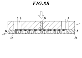
しかしながら、図8Bに示すように、押しネジ41をねじ込んでグレーチング34及び陽極32を陽イオン交換膜31に押圧した場合、筐体11とグレーチング34との間に隙間Sが生じる。その結果、筐体11に形成された原料水供給路5から供給された原料水が、当該隙間S内を流れ、余計な箇所を原料水が流れることとなり、陽イオン交換膜31に原料水を効率良く供給することができない。そのため、オゾン水生成効率が低下し、高濃度のオゾン水を生成することができないという問題がある。
本発明は、上記事情に鑑みてなされたもので、オゾン水の生成効率が高く、また、高濃度のオゾン水を生成することができるオゾン水生成装置を提供することを目的としている。 However, as shown in FIG. 8B, when thepush screw 41 is screwed and the grating 34 and the anode 32 are pressed against the cation exchange membrane 31, a gap S is generated between the housing 11 and the grating 34. As a result, the raw water supplied from the raw water supply path 5 formed in the housing 11 flows through the gap S, and the raw water flows through an extra portion. The raw water is supplied to the cation exchange membrane 31. It cannot be supplied efficiently. Therefore, there exists a problem that ozone water production | generation efficiency falls and high concentration ozone water cannot be produced | generated.
This invention is made | formed in view of the said situation, and it aims at providing the ozone water production | generation apparatus which can produce | generate high concentration ozone water with high production | generation efficiency of ozone water.
本発明は、上記事情に鑑みてなされたもので、オゾン水の生成効率が高く、また、高濃度のオゾン水を生成することができるオゾン水生成装置を提供することを目的としている。 However, as shown in FIG. 8B, when the
This invention is made | formed in view of the said situation, and it aims at providing the ozone water production | generation apparatus which can produce | generate high concentration ozone water with high production | generation efficiency of ozone water.
本発明によれば、第1筐体と、
前記第1筐体に重ね合わされる第2筐体と、
前記第1筐体及び第2筐体を重ね合わせることによって形成された収容室に収容された触媒電極と、を備え、
前記触媒電極が、前記第1筐体側から陽極、陽イオン交換膜及び陰極の順に設けられてなり、
前記触媒電極に原料水を供給するとともに前記陽極及び前記陰極間に直流電圧を印加することによってオゾン水を生成するオゾン水生成装置であって、
前記第1筐体には、前記収容室に連通し、原料水を前記触媒電極の前記陽極に供給する陽極用供給流路及び生成された生成水を排出する陽極用排出流路が設けられ、
前記第2筐体には、前記収容室に連通し、原料水を前記触媒電極の前記陰極に供給する陰極用供給流路及び生成された生成水を排出する陰極用排出流路が設けられ、
前記陽極と前記第1筐体との間、または前記陰極と前記第2筐体との間の少なくとも一方にクッション材が設けられ、
前記第1筐体または前記第2筐体の少なくとも一方に、当該第1筐体または第2筐体を貫通し、前記クッション材を前記触媒電極側に向けて押圧するか、あるいは、当該第1筐体または第2筐体を貫通し、前記触媒電極を直接押圧する押圧部材が設けられ、
前記押圧部材は、前記触媒電極の少なくとも中央部を押圧する位置に配置され、
前記押圧部材による前記触媒電極の押圧によって、前記陽極、前記陽イオン交換膜及び前記陰極が圧接されていることを特徴とするオゾン水生成装置が提供される。 According to the present invention, a first housing;
A second housing overlaid on the first housing;
A catalyst electrode housed in a housing chamber formed by overlapping the first housing and the second housing,
The catalyst electrode is provided in the order of an anode, a cation exchange membrane, and a cathode from the first housing side,
An ozone water generating device that supplies raw water to the catalyst electrode and generates ozone water by applying a DC voltage between the anode and the cathode,
The first casing is provided with an anode supply channel that communicates with the storage chamber and supplies raw water to the anode of the catalyst electrode, and an anode discharge channel that discharges the generated generated water.
The second casing is provided with a cathode supply channel that communicates with the storage chamber and supplies raw water to the cathode of the catalyst electrode and a cathode discharge channel that discharges the generated generated water.
A cushion material is provided between at least one of the anode and the first casing or between the cathode and the second casing,
At least one of the first housing or the second housing penetrates the first housing or the second housing and presses the cushion material toward the catalyst electrode side, or the first housing A pressing member that penetrates the casing or the second casing and directly presses the catalyst electrode is provided,
The pressing member is disposed at a position that presses at least the center of the catalyst electrode,
An ozone water generator is provided in which the anode, the cation exchange membrane, and the cathode are pressed against each other by pressing the catalyst electrode by the pressing member.
好ましくは、前記押圧部材は、複数設けられ、
複数の前記押圧部材は、前記触媒電極の少なくとも中央部を押圧する位置において、等間隔に配置されている。 Preferably, a plurality of the pressing members are provided,
The plurality of pressing members are arranged at equal intervals at a position where at least the central portion of the catalyst electrode is pressed.
複数の前記押圧部材は、前記触媒電極の少なくとも中央部を押圧する位置において、等間隔に配置されている。 Preferably, a plurality of the pressing members are provided,
The plurality of pressing members are arranged at equal intervals at a position where at least the central portion of the catalyst electrode is pressed.
好ましくは、前記クッション材は、シリコン製である。
Preferably, the cushion material is made of silicon.
本発明によれば、オゾン水の生成効率が高く、また、高濃度のオゾン水を生成することができる。
According to the present invention, the generation efficiency of ozone water is high, and high concentration ozone water can be generated.
以下、本発明の実施形態について、図面を参照しながら説明する。
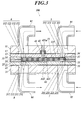
図1は、オゾン水生成装置の外観斜視図、図2は、オゾン水生成装置の分解斜視図、図3は、図2における切断線I-Iに沿って切断した際の矢視断面図である。
図1~図3に示すように、本発明に係るオゾン水生成装置100は、第1筐体1と、第1筐体1に重ね合わされる第2筐体2と、これら第1筐体1及び第2筐体2の重ね合わせ面に形成された収容室144,244に収容される触媒電極3と、を備えている。
触媒電極3は、陽イオン交換膜31と、陽イオン交換膜31の一方の面に設けられた陽極32と、陽イオン交換膜31の他方の面に設けられた陰極33と、を備えている。第1筐体1側から、陽極32、陽イオン交換膜31、陰極33、第2筐体2の順に配置されている。
オゾン水生成装置100は、陽極32及び陰極33にそれぞれ原料水を供給するとともに陽極32及び陰極33間に直流電圧を印加することによって、陽極32側に微細オゾン気泡を発生させて、微細オゾン気泡を水に溶解させることにより、オゾン水を生成する。なお、陰極33側には、水素が発生し、水素が水に溶解して水素水(陰極水)が生成される。 Hereinafter, embodiments of the present invention will be described with reference to the drawings.
1 is an external perspective view of an ozone water generator, FIG. 2 is an exploded perspective view of the ozone water generator, and FIG. 3 is a cross-sectional view taken along the cutting line II in FIG. is there.
As shown in FIGS. 1 to 3, an ozonewater generating apparatus 100 according to the present invention includes a first housing 1, a second housing 2 superimposed on the first housing 1, and the first housing 1. And the catalyst electrode 3 accommodated in the accommodating chambers 144 and 244 formed on the overlapping surface of the second casing 2.
Thecatalyst electrode 3 includes a cation exchange membrane 31, an anode 32 provided on one surface of the cation exchange membrane 31, and a cathode 33 provided on the other surface of the cation exchange membrane 31. . From the first housing 1 side, the anode 32, the cation exchange membrane 31, the cathode 33, and the second housing 2 are arranged in this order.
The ozonewater generating apparatus 100 supplies raw water to the anode 32 and the cathode 33 and applies a DC voltage between the anode 32 and the cathode 33 to generate fine ozone bubbles on the anode 32 side. Is dissolved in water to produce ozone water. Note that hydrogen is generated on the cathode 33 side, and hydrogen is dissolved in water to generate hydrogen water (cathode water).
図1は、オゾン水生成装置の外観斜視図、図2は、オゾン水生成装置の分解斜視図、図3は、図2における切断線I-Iに沿って切断した際の矢視断面図である。
図1~図3に示すように、本発明に係るオゾン水生成装置100は、第1筐体1と、第1筐体1に重ね合わされる第2筐体2と、これら第1筐体1及び第2筐体2の重ね合わせ面に形成された収容室144,244に収容される触媒電極3と、を備えている。
触媒電極3は、陽イオン交換膜31と、陽イオン交換膜31の一方の面に設けられた陽極32と、陽イオン交換膜31の他方の面に設けられた陰極33と、を備えている。第1筐体1側から、陽極32、陽イオン交換膜31、陰極33、第2筐体2の順に配置されている。
オゾン水生成装置100は、陽極32及び陰極33にそれぞれ原料水を供給するとともに陽極32及び陰極33間に直流電圧を印加することによって、陽極32側に微細オゾン気泡を発生させて、微細オゾン気泡を水に溶解させることにより、オゾン水を生成する。なお、陰極33側には、水素が発生し、水素が水に溶解して水素水(陰極水)が生成される。 Hereinafter, embodiments of the present invention will be described with reference to the drawings.
1 is an external perspective view of an ozone water generator, FIG. 2 is an exploded perspective view of the ozone water generator, and FIG. 3 is a cross-sectional view taken along the cutting line II in FIG. is there.
As shown in FIGS. 1 to 3, an ozone
The
The ozone
第1筐体1は、最も外側に配置される第1狭持板11と、第1狭持板11の内側に配置される第1保持板13と、第1狭持板11及び第1保持板13の間に配置される第1シート材12と、を備えている。
第1保持板13の内側には、第1パッキン材14が設けられている。また、第1パッキン材14に形成された貫通穴(収容室144)に、第1クッション材15、陽極32及びグレーチング34が収容されている。 Thefirst housing 1 includes a first holding plate 11 disposed on the outermost side, a first holding plate 13 disposed on the inner side of the first holding plate 11, the first holding plate 11 and the first holding. And a first sheet material 12 disposed between the plates 13.
Afirst packing material 14 is provided inside the first holding plate 13. Further, the first cushion material 15, the anode 32, and the grating 34 are accommodated in a through hole (accommodating chamber 144) formed in the first packing material 14.
第1保持板13の内側には、第1パッキン材14が設けられている。また、第1パッキン材14に形成された貫通穴(収容室144)に、第1クッション材15、陽極32及びグレーチング34が収容されている。 The
A
第1狭持板11は、円板状をなしており、例えば、プラスチック製とすることが好ましい。第1狭持板11には、表裏面を貫通して形成された陽極用供給流路111及び排出流路112が形成されている。
陽極用供給流路111には、外部から陽極32に原料水を供給するための陽極用供給管91が嵌め込まれるようになっている。
陽極用排出流路112には、生成水(オゾン水)を外部に排出するための陽極用排出管92が嵌め込まれるようになっている。
これら陽極用供給流路111及び陽極用排出流路112の周囲に複数のボルト貫通穴113が等間隔に形成されている。
また、第1狭持板11の中央部には、3つの押圧部材用貫通穴114が等間隔に形成されている。押圧部材用貫通穴114には、押しネジ41がねじ込まれるとともに、ねじ込まれた押しネジ41によって押圧される凸状部材42の凸状部先端421aが嵌めこまれるようになっている。また、凸状部材42の凸状部先端421aの外周には、Oリング43が設けられており、Oリング43によって水密性を確保している(図3参照)。
なお、陽極用供給管91は、図示しないが、例えば、原料水が貯留されたタンクに接続されたり、水道管に接続されている。また、陽極用排出管92は、例えば、生成されたオゾン水を貯留するためのタンクや、オゾン水を吐出させるノズル等に接続されている。
また、陽極用供給管91に供給する原料水としては、水道水、精製水などが挙げられる。 Thefirst holding plate 11 has a disk shape, and is preferably made of plastic, for example. An anode supply channel 111 and a discharge channel 112 are formed in the first sandwiching plate 11 so as to penetrate the front and back surfaces.
Ananode supply pipe 91 for supplying raw material water to the anode 32 from the outside is fitted into the anode supply channel 111.
Ananode discharge pipe 92 for discharging generated water (ozone water) to the outside is fitted into the anode discharge flow path 112.
A plurality of bolt throughholes 113 are formed at equal intervals around the anode supply channel 111 and the anode discharge channel 112.
Further, three pressing member throughholes 114 are formed at equal intervals in the central portion of the first holding plate 11. A pressing screw 41 is screwed into the pressing member through hole 114, and a convex portion tip 421a of the convex member 42 pressed by the screwed pressing screw 41 is fitted therein. Further, an O-ring 43 is provided on the outer periphery of the convex portion tip 421a of the convex member 42, and the O-ring 43 ensures water tightness (see FIG. 3).
Although not shown, theanode supply pipe 91 is connected to, for example, a tank in which raw water is stored or is connected to a water pipe. The anode discharge pipe 92 is connected to, for example, a tank for storing generated ozone water, a nozzle for discharging ozone water, and the like.
Examples of the raw water supplied to theanode supply pipe 91 include tap water and purified water.
陽極用供給流路111には、外部から陽極32に原料水を供給するための陽極用供給管91が嵌め込まれるようになっている。
陽極用排出流路112には、生成水(オゾン水)を外部に排出するための陽極用排出管92が嵌め込まれるようになっている。
これら陽極用供給流路111及び陽極用排出流路112の周囲に複数のボルト貫通穴113が等間隔に形成されている。
また、第1狭持板11の中央部には、3つの押圧部材用貫通穴114が等間隔に形成されている。押圧部材用貫通穴114には、押しネジ41がねじ込まれるとともに、ねじ込まれた押しネジ41によって押圧される凸状部材42の凸状部先端421aが嵌めこまれるようになっている。また、凸状部材42の凸状部先端421aの外周には、Oリング43が設けられており、Oリング43によって水密性を確保している(図3参照)。
なお、陽極用供給管91は、図示しないが、例えば、原料水が貯留されたタンクに接続されたり、水道管に接続されている。また、陽極用排出管92は、例えば、生成されたオゾン水を貯留するためのタンクや、オゾン水を吐出させるノズル等に接続されている。
また、陽極用供給管91に供給する原料水としては、水道水、精製水などが挙げられる。 The
An
An
A plurality of bolt through
Further, three pressing member through
Although not shown, the
Examples of the raw water supplied to the
第1保持板13は、第1狭持板11と平面視が同じ大きさの円板状をなしており、第1狭持板11の厚さよりも薄くなっている。
第1保持板13は、例えば、金属製とすること好ましい。
第1保持板13には、第1狭持板11の陽極用供給流路111及び陽極用排出流路112に対応する位置にそれぞれ陽極用供給流路131及び陽極用排出流路132が形成されている。
また、これら陽極用供給流路131及び陽極用排出流路132の周囲で、第1狭持板11のボルト貫通穴113に対応する位置に、複数のボルト貫通穴133が等間隔に形成されている。
また、第1保持板13の中央部で、第1狭持板11の押圧部材用貫通穴114に対応する位置に、3つの押圧部材用貫通穴134が等間隔に形成されている。押圧部材用貫通穴134には、凸状部材42の凸状部421の一部が嵌め込まれるようになっている。 Thefirst holding plate 13 has a disk shape that is the same size as the first holding plate 11 in plan view, and is thinner than the thickness of the first holding plate 11.
Thefirst holding plate 13 is preferably made of metal, for example.
Thefirst holding plate 13 is formed with an anode supply channel 131 and an anode discharge channel 132 at positions corresponding to the anode supply channel 111 and the anode discharge channel 112 of the first holding plate 11, respectively. ing.
A plurality of bolt throughholes 133 are formed at equal intervals around the anode supply channel 131 and the anode discharge channel 132 at positions corresponding to the bolt through holes 113 of the first holding plate 11. Yes.
In addition, at the center of the first holdingplate 13, three pressing member through holes 134 are formed at equal intervals at positions corresponding to the pressing member through holes 114 of the first holding plate 11. A part of the convex portion 421 of the convex member 42 is fitted into the pressing member through hole 134.
第1保持板13は、例えば、金属製とすること好ましい。
第1保持板13には、第1狭持板11の陽極用供給流路111及び陽極用排出流路112に対応する位置にそれぞれ陽極用供給流路131及び陽極用排出流路132が形成されている。
また、これら陽極用供給流路131及び陽極用排出流路132の周囲で、第1狭持板11のボルト貫通穴113に対応する位置に、複数のボルト貫通穴133が等間隔に形成されている。
また、第1保持板13の中央部で、第1狭持板11の押圧部材用貫通穴114に対応する位置に、3つの押圧部材用貫通穴134が等間隔に形成されている。押圧部材用貫通穴134には、凸状部材42の凸状部421の一部が嵌め込まれるようになっている。 The
The
The
A plurality of bolt through
In addition, at the center of the first holding
第1シート材12は、第1狭持板11と第1保持板13との間に設けられ、第1狭持板11及び第1保持板13の間の水密性を確保するためのパッキンとして機能する。第1シート材12は、第1狭持板11及び第1保持板13と平面視が同じ大きさの円板状をなしており、例えば、シリコン製とすることが好ましい。
また、第1シート材12には、第1狭持板11の陽極用供給流路111及び陽極用排出流路112に対応する位置にそれぞれ陽極用供給流路121及び陽極用排出流路122が形成されている。
また、陽極用供給流路121及び陽極用排出流路122の周囲に複数のボルト貫通穴123が形成されている。
また、第1シート材12の中央部で、第1狭持板11の押圧部材用貫通穴114に対応する位置に、3つの押圧部材用貫通穴124が等間隔に形成されている。押圧部材用貫通穴124には、凸状部材42の凸状部421の一部が嵌め込まれるようになっている。 Thefirst sheet material 12 is provided between the first holding plate 11 and the first holding plate 13 and is used as a packing for ensuring water tightness between the first holding plate 11 and the first holding plate 13. Function. The first sheet material 12 has a disk shape having the same size as the first holding plate 11 and the first holding plate 13 in plan view, and is preferably made of silicon, for example.
Thefirst sheet material 12 includes an anode supply channel 121 and an anode discharge channel 122 at positions corresponding to the anode supply channel 111 and the anode discharge channel 112 of the first holding plate 11, respectively. Is formed.
Further, a plurality of bolt throughholes 123 are formed around the anode supply channel 121 and the anode discharge channel 122.
In addition, three pressing member throughholes 124 are formed at equal intervals in the center portion of the first sheet material 12 at positions corresponding to the pressing member through holes 114 of the first holding plate 11. A part of the convex portion 421 of the convex member 42 is fitted in the pressing member through hole 124.
また、第1シート材12には、第1狭持板11の陽極用供給流路111及び陽極用排出流路112に対応する位置にそれぞれ陽極用供給流路121及び陽極用排出流路122が形成されている。
また、陽極用供給流路121及び陽極用排出流路122の周囲に複数のボルト貫通穴123が形成されている。
また、第1シート材12の中央部で、第1狭持板11の押圧部材用貫通穴114に対応する位置に、3つの押圧部材用貫通穴124が等間隔に形成されている。押圧部材用貫通穴124には、凸状部材42の凸状部421の一部が嵌め込まれるようになっている。 The
The
Further, a plurality of bolt through
In addition, three pressing member through
第1パッキン材14は、第1保持板13の内側に設けられて、第1狭持板11及び第1保持板13と平面視が同じ大きさの円板状をなしており、例えば、フッ素系樹脂、パイトンゴム、エチレンプロピレンゴム、ガスケット材などからなるものを使用することが好ましい。なお、第1パッキン材14の硬度は、後述する陽極32(基板321)の硬度より低くなっている。
第1パッキン材14には、中央に平面視円形状の貫通穴である収容室144が形成されている。後述するが、この収容室144に触媒電極3の陽極32、グレーチング34及び第1クッション材15が収容されるようになっている。すなわち、陽極32、グレーチング34及び第1クッション材15の外周が第1パッキン材14によって囲まれて保護される。
また、収容室144の周囲には、複数のボルト貫通穴143が形成されている。 Thefirst packing material 14 is provided inside the first holding plate 13 and has a disk shape having the same size as the first holding plate 11 and the first holding plate 13, for example, fluorine. It is preferable to use a material made of a resin, pieton rubber, ethylene propylene rubber, gasket material, or the like. In addition, the hardness of the 1st packing material 14 is lower than the hardness of the anode 32 (board | substrate 321) mentioned later.
Thefirst packing material 14 is formed with a housing chamber 144 that is a through hole having a circular shape in plan view at the center. As will be described later, the anode 32, the grating 34, and the first cushion material 15 of the catalyst electrode 3 are accommodated in the accommodation chamber 144. That is, the outer periphery of the anode 32, the grating 34, and the first cushion material 15 is surrounded and protected by the first packing material 14.
A plurality of bolt throughholes 143 are formed around the accommodation chamber 144.
第1パッキン材14には、中央に平面視円形状の貫通穴である収容室144が形成されている。後述するが、この収容室144に触媒電極3の陽極32、グレーチング34及び第1クッション材15が収容されるようになっている。すなわち、陽極32、グレーチング34及び第1クッション材15の外周が第1パッキン材14によって囲まれて保護される。
また、収容室144の周囲には、複数のボルト貫通穴143が形成されている。 The
The
A plurality of bolt through
第1クッション材15は、第1パッキン材14の収容室144に収容され、陽極32及びグレーチング34に荷重が加わった際の荷重を吸収する機能を有している。
第1クッション材15は、第1挟持板11よりも平面視が小さな円板状をなしている。第1クッション材15の硬度は、第1パッキン材14の硬度と同じ、または、第1パッキン材14の硬度よりも低く、第1クッション材15は、例えば、シリコン製(シリコンゴム、シリコンスポンジ)とすることが好ましい。
第1クッション材15には、第1保持板13の陽極用供給流路131及び陽極用排出流路132に対応する位置にそれぞれ陽極用供給流路151及び陽極用排出流路152が形成されている。
また、第1クッション材15の中央部で、第1狭持板11の押圧部材用貫通穴114に対応する位置に、3つの押圧部材用貫通穴154が等間隔に形成されている。押圧部材用貫通穴154には、凸状部材42の底部422が嵌め込まれるようになっている。 Thefirst cushion material 15 is accommodated in the accommodation chamber 144 of the first packing material 14 and has a function of absorbing a load when a load is applied to the anode 32 and the grating 34.
Thefirst cushion material 15 has a disk shape that is smaller in plan view than the first clamping plate 11. The hardness of the first cushion material 15 is the same as the hardness of the first packing material 14 or lower than the hardness of the first packing material 14, and the first cushion material 15 is made of, for example, silicon (silicon rubber, silicon sponge) It is preferable that
In thefirst cushion material 15, an anode supply channel 151 and an anode discharge channel 152 are formed at positions corresponding to the anode supply channel 131 and the anode discharge channel 132 of the first holding plate 13, respectively. Yes.
In addition, three pressing member throughholes 154 are formed at equal intervals in the center portion of the first cushion material 15 at positions corresponding to the pressing member through holes 114 of the first holding plate 11. The bottom portion 422 of the convex member 42 is fitted into the pressing member through hole 154.
第1クッション材15は、第1挟持板11よりも平面視が小さな円板状をなしている。第1クッション材15の硬度は、第1パッキン材14の硬度と同じ、または、第1パッキン材14の硬度よりも低く、第1クッション材15は、例えば、シリコン製(シリコンゴム、シリコンスポンジ)とすることが好ましい。
第1クッション材15には、第1保持板13の陽極用供給流路131及び陽極用排出流路132に対応する位置にそれぞれ陽極用供給流路151及び陽極用排出流路152が形成されている。
また、第1クッション材15の中央部で、第1狭持板11の押圧部材用貫通穴114に対応する位置に、3つの押圧部材用貫通穴154が等間隔に形成されている。押圧部材用貫通穴154には、凸状部材42の底部422が嵌め込まれるようになっている。 The
The
In the
In addition, three pressing member through
押しネジ41は、第1狭持板11の押圧部材用貫通穴114のうち上側部分に、ねじ込まれるようになっている。
凸状部材42は、側断面視逆T字型をなしており、底部422と、底部422から突出する凸状部421と、を備えている。
底部422は、第1クッション材15の押圧部材用貫通穴154に嵌めこまれている。凸状部421は、第1保持板13、第1シート材12及び第1狭持板11の各押圧部材用貫通穴134,124,114に嵌め込まれて、凸状部先端421aの外周には、Oリング43が設けられ、これによって水密性が確保されている。 Thepush screw 41 is screwed into the upper part of the through hole 114 for the pressing member of the first holding plate 11.
Theconvex member 42 has an inverted T-shape in a side sectional view, and includes a bottom portion 422 and a convex portion 421 protruding from the bottom portion 422.
Thebottom portion 422 is fitted in the pressing member through hole 154 of the first cushion material 15. The convex portion 421 is fitted into the pressing member through holes 134, 124, 114 of the first holding plate 13, the first sheet material 12, and the first holding plate 11, and on the outer periphery of the convex portion tip 421 a. , An O-ring 43 is provided to ensure watertightness.
凸状部材42は、側断面視逆T字型をなしており、底部422と、底部422から突出する凸状部421と、を備えている。
底部422は、第1クッション材15の押圧部材用貫通穴154に嵌めこまれている。凸状部421は、第1保持板13、第1シート材12及び第1狭持板11の各押圧部材用貫通穴134,124,114に嵌め込まれて、凸状部先端421aの外周には、Oリング43が設けられ、これによって水密性が確保されている。 The
The
The
そして、押しネジ41を第1狭持板11の押圧部材用貫通穴114にねじ込むことによって、凸状部材42の凸状部先端421aを下方(触媒電極3側)に押し込み、後述するグレーチング34を介して、陽極32、陽イオン交換膜31及び陰極33を押圧して圧接するようになっている。
Then, by screwing the push screw 41 into the pressing member through hole 114 of the first holding plate 11, the convex portion tip 421a of the convex member 42 is pushed downward (catalyst electrode 3 side), and a grating 34 described later is provided. The anode 32, the cation exchange membrane 31 and the cathode 33 are pressed and pressed.
図1~図3に示すように、第2筐体2は、最も外側に配置される第2狭持板21と、第2狭持板21の内側に配置される第2保持板23と、第2狭持板21及び第2保持板23の間に配置される第2シート材22と、を備えている。
第2保持板23の内側には、第2パッキン材24が設けられている。また、第2パッキン材24に形成された貫通穴(収容室244)に、第2クッション材25、陰極33及びグレーチング35が収容されている。 As shown in FIGS. 1 to 3, thesecond housing 2 includes a second holding plate 21 disposed on the outermost side, a second holding plate 23 disposed on the inner side of the second holding plate 21, And a second sheet material 22 disposed between the second holding plate 21 and the second holding plate 23.
Asecond packing material 24 is provided inside the second holding plate 23. The second cushion material 25, the cathode 33, and the grating 35 are accommodated in a through hole (accommodating chamber 244) formed in the second packing material 24.
第2保持板23の内側には、第2パッキン材24が設けられている。また、第2パッキン材24に形成された貫通穴(収容室244)に、第2クッション材25、陰極33及びグレーチング35が収容されている。 As shown in FIGS. 1 to 3, the
A
第2狭持板21は、円板状をなしており、例えば、プラスチック製とすることが好ましい。
第2狭持板21には、表裏面を貫通して形成された陰極用供給流路211及び陰極用排出流路212が形成されている。
陰極用供給流路211には、外部から陰極33に原料水を供給するための陰極用供給管93が嵌め込まれるようになっている。
陰極用排出流路212には、生成水(陰極水)を外部に排出するための陰極用排出管94が嵌め込まれるようになっている。
これら陰極用供給流路211及び陰極用排出流路212の周囲に複数のボルト貫通穴213が等間隔に形成されている。
なお、陰極用供給管93は、図示しないが、例えば、原料水が貯留されたタンクに接続されたり、水道管に接続されている。また、陰極用排出管94は、例えば、生成された陰極水を貯留するためのタンクに接続されている。
また、陰極用供給管93に供給する原料水としては、水道水、精製水などが挙げられる。 Thesecond sandwiching plate 21 has a disc shape, and is preferably made of plastic, for example.
Thesecond holding plate 21 is formed with a cathode supply channel 211 and a cathode discharge channel 212 formed so as to penetrate the front and back surfaces.
Acathode supply pipe 93 for supplying raw material water to the cathode 33 from the outside is fitted into the cathode supply channel 211.
Acathode discharge pipe 94 for discharging generated water (cathode water) to the outside is fitted into the cathode discharge channel 212.
A plurality of bolt throughholes 213 are formed at equal intervals around the cathode supply channel 211 and the cathode discharge channel 212.
Although not shown, thecathode supply pipe 93 is connected to, for example, a tank in which raw water is stored or is connected to a water pipe. Further, the cathode discharge pipe 94 is connected to, for example, a tank for storing the generated cathode water.
Examples of the raw water supplied to thecathode supply pipe 93 include tap water and purified water.
第2狭持板21には、表裏面を貫通して形成された陰極用供給流路211及び陰極用排出流路212が形成されている。
陰極用供給流路211には、外部から陰極33に原料水を供給するための陰極用供給管93が嵌め込まれるようになっている。
陰極用排出流路212には、生成水(陰極水)を外部に排出するための陰極用排出管94が嵌め込まれるようになっている。
これら陰極用供給流路211及び陰極用排出流路212の周囲に複数のボルト貫通穴213が等間隔に形成されている。
なお、陰極用供給管93は、図示しないが、例えば、原料水が貯留されたタンクに接続されたり、水道管に接続されている。また、陰極用排出管94は、例えば、生成された陰極水を貯留するためのタンクに接続されている。
また、陰極用供給管93に供給する原料水としては、水道水、精製水などが挙げられる。 The
The
A
A
A plurality of bolt through
Although not shown, the
Examples of the raw water supplied to the
第2保持板23は、第2狭持板21と平面視が同じ大きさの円板状をなしており、第2狭持板21の厚さよりも薄くなっている。
第2保持板23は、例えば、金属製とすることが好ましい。
第2保持板23には、第2狭持板21の陰極用供給流路211及び陰極用排出流路212に対応する位置にそれぞれ陰極用供給流路231及び陰極用排出流路232が形成されている。
また、これら陰極用供給流路231及び陰極用排出流路232の周囲で、第2狭持板21のボルト貫通穴213に対応する位置に、複数のボルト貫通穴233が等間隔に形成されている。 Thesecond holding plate 23 has a disk shape with the same size as the second holding plate 21 in plan view, and is thinner than the thickness of the second holding plate 21.
For example, thesecond holding plate 23 is preferably made of metal.
In thesecond holding plate 23, a cathode supply channel 231 and a cathode discharge channel 232 are formed at positions corresponding to the cathode supply channel 211 and the cathode discharge channel 212 of the second holding plate 21, respectively. ing.
A plurality of bolt throughholes 233 are formed at equal intervals around the cathode supply flow channel 231 and the cathode discharge flow channel 232 at positions corresponding to the bolt through holes 213 of the second holding plate 21. Yes.
第2保持板23は、例えば、金属製とすることが好ましい。
第2保持板23には、第2狭持板21の陰極用供給流路211及び陰極用排出流路212に対応する位置にそれぞれ陰極用供給流路231及び陰極用排出流路232が形成されている。
また、これら陰極用供給流路231及び陰極用排出流路232の周囲で、第2狭持板21のボルト貫通穴213に対応する位置に、複数のボルト貫通穴233が等間隔に形成されている。 The
For example, the
In the
A plurality of bolt through
第2シート材22は、第2狭持板21と第2保持板23との間に設けられ、第2狭持板21及び第2保持板23の間の水密性を確保するためのパッキンとして機能する。第2シート材22は、第2狭持板21及び第2保持板23と平面視が同じ大きさの円板状をなしており、例えば、シリコン製とすることが好ましい。
また、第2シート材22には、第2狭持板21の陰極用供給流路211及び陰極用排出流路212に対応する位置にそれぞれ陰極用供給流路221及び陰極用排出流路222が形成されている。
また、陰極用供給流路221及び陰極用排出流路222の周囲に複数のボルト貫通穴223が形成されている。 Thesecond sheet material 22 is provided between the second holding plate 21 and the second holding plate 23 as a packing for ensuring watertightness between the second holding plate 21 and the second holding plate 23. Function. The second sheet material 22 has a disk shape having the same size as the second holding plate 21 and the second holding plate 23 in plan view, and is preferably made of silicon, for example.
Further, thesecond sheet material 22 has a cathode supply channel 221 and a cathode discharge channel 222 at positions corresponding to the cathode supply channel 211 and the cathode discharge channel 212 of the second sandwiching plate 21, respectively. Is formed.
In addition, a plurality of bolt throughholes 223 are formed around the cathode supply channel 221 and the cathode discharge channel 222.
また、第2シート材22には、第2狭持板21の陰極用供給流路211及び陰極用排出流路212に対応する位置にそれぞれ陰極用供給流路221及び陰極用排出流路222が形成されている。
また、陰極用供給流路221及び陰極用排出流路222の周囲に複数のボルト貫通穴223が形成されている。 The
Further, the
In addition, a plurality of bolt through
第2パッキン材24は、第2保持板23の内側に設けられて、第1狭持板21及び第1保持板23と平面視が同じ大きさの円板状をなしており、例えば、フッ素系樹脂、パイトンゴム、エチレンプロピレンゴム、ガスケット材などからなるものを使用することが好ましい。なお、第2パッキン材24の硬度は、陰極33の硬度より低いことが好ましい。
第2パッキン材24には、第1パッキン材14の収容室144と同様に平面視円形状の貫通穴である収容室244が形成されている。後述するが、この収容室244に、触媒電極3の陰極33及びグレーチング35がそれぞれ収容されるようになっている。すなわち、陰極33及びグレーチング35の外周が第2パッキン材24によって囲まれて保護される。
また、収容室244の周囲には、複数のボルト貫通穴243が形成されている。 Thesecond packing material 24 is provided inside the second holding plate 23 and has a disk shape having the same size as the first holding plate 21 and the first holding plate 23 in plan view. It is preferable to use a material made of a resin, pieton rubber, ethylene propylene rubber, gasket material, or the like. The hardness of the second packing material 24 is preferably lower than the hardness of the cathode 33.
Thesecond packing material 24 is formed with a storage chamber 244 that is a through hole having a circular shape in plan view, similar to the storage chamber 144 of the first packing material 14. As will be described later, the cathode 33 and the grating 35 of the catalyst electrode 3 are accommodated in the accommodating chamber 244, respectively. That is, the outer periphery of the cathode 33 and the grating 35 is surrounded and protected by the second packing material 24.
A plurality of bolt throughholes 243 are formed around the storage chamber 244.
第2パッキン材24には、第1パッキン材14の収容室144と同様に平面視円形状の貫通穴である収容室244が形成されている。後述するが、この収容室244に、触媒電極3の陰極33及びグレーチング35がそれぞれ収容されるようになっている。すなわち、陰極33及びグレーチング35の外周が第2パッキン材24によって囲まれて保護される。
また、収容室244の周囲には、複数のボルト貫通穴243が形成されている。 The
The
A plurality of bolt through
第2クッション材25は、第2保持板23と第2パッキン材24との間に設けられ、第2パッキン材24及び陰極33に荷重が加わった際の荷重を吸収する機能を有している。
第2クッション材25は、第2パッキン材24と平面視が同じ大きさの円板状をなしており、第2パッキン材24の硬度と同じ、または、第2パッキン材24の硬度よりも低い、例えば、シリコン製(シリコンゴム、シリコンスポンジ)とすることが好ましい。
第2クッション材25の硬度を第2パッキン材24の硬度と同じ、または、第2パッキン材24の硬度よりも低くすることによって、オゾン水生成装置100を組み立てる際(圧接時)に、第2パッキン材24が第2クッション材25に押し込まれることになる。その結果、第2パッキン材24がストッパーとして機能し、陰極33に加わる荷重を低減でき、陰極33の割れを防止することができるという効果が得られる。
第2クッション材25には、第2保持板23の陰極用供給流路231及び陰極用排出流路232に対応する位置にそれぞれ陰極用供給流路251及び陰極用排出流路252が形成されている。
また、陰極用供給流路251及び陰極用排出流路252の周囲に複数のボルト貫通穴253が形成されている。 Thesecond cushion material 25 is provided between the second holding plate 23 and the second packing material 24 and has a function of absorbing a load when a load is applied to the second packing material 24 and the cathode 33. .
Thesecond cushion material 25 has a disk shape with the same size as the second packing material 24 in plan view, and is the same as the hardness of the second packing material 24 or lower than the hardness of the second packing material 24. For example, it is preferable to use silicon (silicon rubber, silicon sponge).
When the ozonewater generating apparatus 100 is assembled (during pressure welding) by making the hardness of the second cushion material 25 the same as the hardness of the second packing material 24 or lower than the hardness of the second packing material 24, The packing material 24 is pushed into the second cushion material 25. As a result, the second packing material 24 functions as a stopper, the load applied to the cathode 33 can be reduced, and the effect that the crack of the cathode 33 can be prevented is obtained.
In thesecond cushion member 25, a cathode supply channel 251 and a cathode discharge channel 252 are formed at positions corresponding to the cathode supply channel 231 and the cathode discharge channel 232 of the second holding plate 23, respectively. Yes.
A plurality of bolt throughholes 253 are formed around the cathode supply channel 251 and the cathode discharge channel 252.
第2クッション材25は、第2パッキン材24と平面視が同じ大きさの円板状をなしており、第2パッキン材24の硬度と同じ、または、第2パッキン材24の硬度よりも低い、例えば、シリコン製(シリコンゴム、シリコンスポンジ)とすることが好ましい。
第2クッション材25の硬度を第2パッキン材24の硬度と同じ、または、第2パッキン材24の硬度よりも低くすることによって、オゾン水生成装置100を組み立てる際(圧接時)に、第2パッキン材24が第2クッション材25に押し込まれることになる。その結果、第2パッキン材24がストッパーとして機能し、陰極33に加わる荷重を低減でき、陰極33の割れを防止することができるという効果が得られる。
第2クッション材25には、第2保持板23の陰極用供給流路231及び陰極用排出流路232に対応する位置にそれぞれ陰極用供給流路251及び陰極用排出流路252が形成されている。
また、陰極用供給流路251及び陰極用排出流路252の周囲に複数のボルト貫通穴253が形成されている。 The
The
When the ozone
In the
A plurality of bolt through
触媒電極3は、陽極32、陽イオン交換膜31、陰極33及びグレーチング34,35を有している。
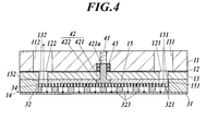
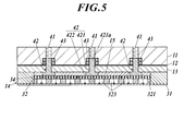
図4は、図2における切断線I-Iに沿って切断した際の、第1パッキン材、第1クッション材、グレーチング、陽極及び陽イオン交換膜の矢視断面図、図5は、図2における切断線II-IIに沿って切断した際の、第1パッキン材、第1クッション材、グレーチング、陽極及び陽イオン交換膜の矢視断面図を示している。 Thecatalyst electrode 3 includes an anode 32, a cation exchange membrane 31, a cathode 33, and gratings 34 and 35.
4 is a cross-sectional view of the first packing material, the first cushion material, the grating, the anode, and the cation exchange membrane when cut along the cutting line II in FIG. 2, and FIG. FIG. 2 is a cross-sectional view of the first packing material, the first cushion material, the grating, the anode, and the cation exchange membrane when cut along a cutting line II-II in FIG.
図4は、図2における切断線I-Iに沿って切断した際の、第1パッキン材、第1クッション材、グレーチング、陽極及び陽イオン交換膜の矢視断面図、図5は、図2における切断線II-IIに沿って切断した際の、第1パッキン材、第1クッション材、グレーチング、陽極及び陽イオン交換膜の矢視断面図を示している。 The
4 is a cross-sectional view of the first packing material, the first cushion material, the grating, the anode, and the cation exchange membrane when cut along the cutting line II in FIG. 2, and FIG. FIG. 2 is a cross-sectional view of the first packing material, the first cushion material, the grating, the anode, and the cation exchange membrane when cut along a cutting line II-II in FIG.
図4及び図5に示すように、陽極32は、平面視円形状の基板321からなる。
基板321としては、オゾン発生触媒機能を有する金属を使用する。具体的には、安定性が良い点で、白金、金又はその被覆金属を使用することが好ましく、特にチタンに白金を被覆した金属を使用すると製造コストを安価に抑えることができる。また、シリコンウェハを使用すると後述するダイヤモンド成膜の密着性がいい(剥離しづらい)ことから最も好ましい。 As shown in FIGS. 4 and 5, theanode 32 includes a substrate 321 having a circular shape in plan view.
As thesubstrate 321, a metal having an ozone generation catalyst function is used. Specifically, it is preferable to use platinum, gold, or a coated metal thereof from the viewpoint of good stability. In particular, when a metal obtained by coating platinum on titanium is used, the manufacturing cost can be reduced. In addition, the use of a silicon wafer is most preferable because the adhesion of diamond film formation described later is good (hard to peel).
基板321としては、オゾン発生触媒機能を有する金属を使用する。具体的には、安定性が良い点で、白金、金又はその被覆金属を使用することが好ましく、特にチタンに白金を被覆した金属を使用すると製造コストを安価に抑えることができる。また、シリコンウェハを使用すると後述するダイヤモンド成膜の密着性がいい(剥離しづらい)ことから最も好ましい。 As shown in FIGS. 4 and 5, the
As the
また、基板321の少なくとも第1筐体側の面にダイヤモンドが成膜されていることが、高濃度のオゾン水を生成できる点で好ましい。
さらに、基板321には、表面から裏面に貫通する多数の貫通穴323が形成されている。貫通穴323の径は、φ0.5~φ3.0程度が好ましい。これら貫通穴323は、後述するグレーチング34を介して、第1狭持板11、第1シート材12、第1保持板13及び第1クッション材15の陽極用供給流路111,121,131,151に連通し、さらに、陽極用排出流路112,122,132,152にも連通している。 In addition, it is preferable that a diamond film is formed on at least the surface of thesubstrate 321 on the first housing side in terms of generating high-concentration ozone water.
Further, thesubstrate 321 is formed with a large number of through holes 323 penetrating from the front surface to the back surface. The diameter of the through hole 323 is preferably about φ0.5 to φ3.0. These through holes 323 are connected to anode supply channels 111, 121, 131, 111 for the first holding plate 11, the first sheet material 12, the first holding plate 13, and the first cushion material 15 through a grating 34 described later. 151, and further communicates with the anode discharge channels 112, 122, 132, and 152.
さらに、基板321には、表面から裏面に貫通する多数の貫通穴323が形成されている。貫通穴323の径は、φ0.5~φ3.0程度が好ましい。これら貫通穴323は、後述するグレーチング34を介して、第1狭持板11、第1シート材12、第1保持板13及び第1クッション材15の陽極用供給流路111,121,131,151に連通し、さらに、陽極用排出流路112,122,132,152にも連通している。 In addition, it is preferable that a diamond film is formed on at least the surface of the
Further, the
ダイヤモンド成膜は、例えば、プラズマCVD法や熱フェラメントCVD法によって成膜することができる。
このような陽極32の製造方法としては、まず、基板321にエッチング、レーザー加工などによって複数の貫通穴323を形成する。さらに、基板321の少なくとも第1筐体側の面に蒸着等によりダイヤモンドを成膜する。 The diamond film can be formed by, for example, a plasma CVD method or a thermal fermentation CVD method.
As a method for manufacturing such ananode 32, first, a plurality of through holes 323 are formed in the substrate 321 by etching, laser processing, or the like. Further, diamond is deposited on the surface of the substrate 321 at least on the first housing side by vapor deposition or the like.
このような陽極32の製造方法としては、まず、基板321にエッチング、レーザー加工などによって複数の貫通穴323を形成する。さらに、基板321の少なくとも第1筐体側の面に蒸着等によりダイヤモンドを成膜する。 The diamond film can be formed by, for example, a plasma CVD method or a thermal fermentation CVD method.
As a method for manufacturing such an
陽極32は、第1パッキン材14の収容室144に収容されて、陽極32の外周が第1パッキン材14に囲まれるようになっている。陽極32の陽イオン交換膜31と反対側の面には、グレーチング34を介して第1クッション材15が配置されるようになっている。
グレーチング34は、陽極32と平面視が同じ大きさの円板状をなしている。グレーチング34としては、例えば、チタン製、ステンレス製等とすることが好ましい。なお、グレーチング34とは、線材を溶接した格子状をなした部材である。
陽極32は、第1パッキン材14の収容室144に嵌め込まれる大きさとなっている。具体的には、陽極32の厚さは、0.5mm~3.0mm程度が好ましく、グレーチング34の厚さは、0.5mm~1.0mm程度が好ましい。第1パッキン材14の厚さNは、1.0mm~4.0mm程度が好ましい。 Theanode 32 is housed in the housing chamber 144 of the first packing material 14 so that the outer periphery of the anode 32 is surrounded by the first packing material 14. The first cushion material 15 is arranged on the surface of the anode 32 opposite to the cation exchange membrane 31 via the grating 34.
The grating 34 has a disk shape having the same size as theanode 32 in plan view. For example, the grating 34 is preferably made of titanium or stainless steel. Note that the grating 34 is a lattice-shaped member in which wires are welded.
Theanode 32 is sized to be fitted into the accommodation chamber 144 of the first packing material 14. Specifically, the thickness of the anode 32 is preferably about 0.5 mm to 3.0 mm, and the thickness of the grating 34 is preferably about 0.5 mm to 1.0 mm. The thickness N of the first packing material 14 is preferably about 1.0 mm to 4.0 mm.
グレーチング34は、陽極32と平面視が同じ大きさの円板状をなしている。グレーチング34としては、例えば、チタン製、ステンレス製等とすることが好ましい。なお、グレーチング34とは、線材を溶接した格子状をなした部材である。
陽極32は、第1パッキン材14の収容室144に嵌め込まれる大きさとなっている。具体的には、陽極32の厚さは、0.5mm~3.0mm程度が好ましく、グレーチング34の厚さは、0.5mm~1.0mm程度が好ましい。第1パッキン材14の厚さNは、1.0mm~4.0mm程度が好ましい。 The
The grating 34 has a disk shape having the same size as the
The
陽イオン交換膜31は、平面視円形状をなしており、第1狭持板11の平面視の大きさと同じである。陽イオン交換膜31の外周には、複数のボルト貫通穴313が等間隔に形成されている。
陽イオン交換膜31としては、従来公知のものを使用することができ、発生するオゾンに耐久性の強いフッ素系陽イオン交換膜を使用することができる。また、厚さは、100~300μm程度が好ましい。 Thecation exchange membrane 31 has a circular shape in plan view and is the same as the size of the first holding plate 11 in plan view. A plurality of bolt through holes 313 are formed at equal intervals on the outer periphery of the cation exchange membrane 31.
As thecation exchange membrane 31, a conventionally known one can be used, and a fluorine-based cation exchange membrane having high durability against the generated ozone can be used. The thickness is preferably about 100 to 300 μm.
陽イオン交換膜31としては、従来公知のものを使用することができ、発生するオゾンに耐久性の強いフッ素系陽イオン交換膜を使用することができる。また、厚さは、100~300μm程度が好ましい。 The
As the
陰極33は、陽極32と同様に平面視円形状の基板331からなる。
基板331としては、オゾン発生触媒機能を有する金属を使用する。具体的には、安定性が良い点で、白金、金又はその被覆金属を使用することが好ましく、特にチタンに白金を被覆した金属を使用すると製造コストを安価に抑えることができる。また、シリコンウェハを使用すると後述するダイヤモンド成膜の密着性がいい(剥離しづらい)ことから最も好ましい。
基板331には、表面から裏面に貫通する多数の貫通穴333が形成されている。貫通穴333の径は、φ0.5~φ3.0程度が好ましい。これら貫通穴333は、後述するグレーチング35を介して、第2狭持板21、第2シート材22、第2保持板23及び第2クッション材25の陰極用供給流路211,221,231,251に連通し、さらに、陰極用排出流路212,222,232,252にも連通している。 Thecathode 33 is formed of a substrate 331 having a circular shape in plan view, like the anode 32.
As thesubstrate 331, a metal having an ozone generation catalyst function is used. Specifically, it is preferable to use platinum, gold, or a coated metal thereof from the viewpoint of good stability. In particular, when a metal obtained by coating platinum on titanium is used, the manufacturing cost can be reduced. In addition, the use of a silicon wafer is most preferable because the adhesion of diamond film formation described later is good (hard to peel).
A large number of throughholes 333 are formed in the substrate 331 so as to penetrate from the front surface to the back surface. The diameter of the through hole 333 is preferably about φ0.5 to φ3.0. These through holes 333 are connected to the cathode supply channels 211, 221, 231, the second holding plate 21, the second sheet material 22, the second holding plate 23, and the second cushion material 25 through a grating 35 described later. 251 and the cathode discharge channels 212, 222, 232, and 252.
基板331としては、オゾン発生触媒機能を有する金属を使用する。具体的には、安定性が良い点で、白金、金又はその被覆金属を使用することが好ましく、特にチタンに白金を被覆した金属を使用すると製造コストを安価に抑えることができる。また、シリコンウェハを使用すると後述するダイヤモンド成膜の密着性がいい(剥離しづらい)ことから最も好ましい。
基板331には、表面から裏面に貫通する多数の貫通穴333が形成されている。貫通穴333の径は、φ0.5~φ3.0程度が好ましい。これら貫通穴333は、後述するグレーチング35を介して、第2狭持板21、第2シート材22、第2保持板23及び第2クッション材25の陰極用供給流路211,221,231,251に連通し、さらに、陰極用排出流路212,222,232,252にも連通している。 The
As the
A large number of through
このような基板331の少なくとも第2筐体側の面に、陽極32の場合と同様にダイヤモンドが成膜されている。
また、陰極33の製造方法は、陽極32と同様の方法により製造することができる。 As in the case of theanode 32, diamond is formed on at least the surface of the substrate 331 on the second housing side.
Further, thecathode 33 can be manufactured by the same method as that for the anode 32.
また、陰極33の製造方法は、陽極32と同様の方法により製造することができる。 As in the case of the
Further, the
なお、上記陽極32及び陰極33は、基板321,331に複数の貫通穴323,333を形成し、さらにダイヤモンド成膜したものを使用したが、これに限らず、陽イオン交換膜31を全面的に覆い隠すように密着するものではなく、多数の通孔を設けて、陽イオン交換膜31に接触部と非接触部とを有して重ねられることができれば、エキスパンドメタル状またはパンチングメタル状のものを使用しても良い。
The anode 32 and the cathode 33 are formed by forming a plurality of through holes 323 and 333 in the substrates 321 and 331 and further forming a diamond film. However, the present invention is not limited to this, and the cation exchange membrane 31 is entirely formed. If it can be overlapped with the cation exchange membrane 31 with a contact portion and a non-contact portion, it can be expanded or punched metal-like. You may use things.
また、陽極32と陰極33との間には、電源装置(図示しない)の出力端が電気的に連結され、直流電圧が印加されるように構成されている。すなわち、陽極32及び陰極33は、各電極32,33に導線を介して電源装置に連結されている。印加する直流電圧は、例えば6~24ボルトの範囲内が好ましい。
Also, an output terminal of a power supply device (not shown) is electrically connected between the anode 32 and the cathode 33 so that a DC voltage is applied. That is, the anode 32 and the cathode 33 are connected to the power supply device via the conductive wires to the electrodes 32 and 33. The DC voltage to be applied is preferably in the range of 6 to 24 volts, for example.
以上のように、陽イオン交換膜31の一方の面に接触するように陽極32が配置され、他方の面に接触するように陰極33が配置され、さらに陽極32及び陰極33の陽イオン交換膜31と反対側の面にグレーチング34,35が配置されて、これらが圧接されて触媒電極3が構成されている。
As described above, the anode 32 is disposed so as to be in contact with one surface of the cation exchange membrane 31, the cathode 33 is disposed so as to be in contact with the other surface, and the cation exchange membrane of the anode 32 and the cathode 33. Gratings 34 and 35 are arranged on the surface opposite to 31, and these are pressed to form the catalyst electrode 3.
オゾン水生成装置100を組み立てる手順としては、図2に示すように、下側の部材から順に、第2狭持板21、第2シート材22、第2保持板23、第2クッション材25及び第2パッキン材24を重ね合わせていき、さらに、第2パッキン材24に形成された収容室244にグレーチング35及び陰極33を収容し、さらに、陽イオン交換膜31及び第1パッキン材14を重ね合わせる。第1パッキン材14に形成された収容室144に陽極32、グレーチング34及び第1クッション材15を収容する。
As a procedure for assembling the ozone water generating apparatus 100, as shown in FIG. 2, the second sandwiching plate 21, the second sheet material 22, the second holding plate 23, the second cushion material 25, and the like in order from the lower member. The second packing material 24 is overlaid, the grating 35 and the cathode 33 are housed in the housing chamber 244 formed in the second packing material 24, and the cation exchange membrane 31 and the first packing material 14 are overlaid. Match. The anode 32, the grating 34, and the first cushion material 15 are accommodated in the accommodation chamber 144 formed in the first packing material 14.
次に、第1クッション材15に形成された押圧部材用貫通穴154に、凸状部材42の底部422を嵌めこむ。
その後、第1クッション材15に、第1保持板13及び第1シート材12を重ね合わせる。このとき、第1保持板13及び第1シート材12に形成された押圧部材用貫通穴134,124に、凸状部材42の凸状部421を嵌めこむ。
さらに、第1シート材12に第1狭持板11を重ね合わせる。このとき、第1狭持板11に形成された押圧部材用貫通穴114に、凸状部材42の凸状部先端421aを嵌めこむ。
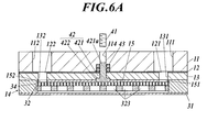
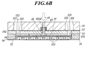
その後、図6Aに示すように、押圧部材用貫通穴114に、押しネジ41をねじ込み、凸状部材42の凸状部先端421aを押し込む。これによって、図6Bに示すように、凸状部材42がグレーチング34を介して陽極32、陽イオン交換膜31及び陰極33を圧接する。
このとき、図6Aで圧縮されていた第1クッション材15が伸張して、グレーチング34と第1保持板13との間に隙間が形成されないように、グレーチング34と第1保持板13との間が密着し、水密性が確保される。したがって、図6Bの点線矢印で示すように、原料水が余計な箇所を流れたり、外部に漏れることなく、陽極32及び陽イオン交換膜31に確実に供給されて、オゾン水を効率良く、高濃度で生成することができる。
また、押しネジ41及び凸状部材42が、陽極32及びグレーチング34の中央部において等間隔に設けられているので、グレーチング34が均一に押圧され、陽極32、陽イオン交換膜31及び陰極33が均一に圧接される。 Next, thebottom portion 422 of the convex member 42 is fitted into the pressing member through hole 154 formed in the first cushion material 15.
Thereafter, the first holdingplate 13 and the first sheet material 12 are overlaid on the first cushion material 15. At this time, the convex portion 421 of the convex member 42 is fitted into the pressing member through holes 134 and 124 formed in the first holding plate 13 and the first sheet material 12.
Further, the first holdingplate 11 is overlaid on the first sheet material 12. At this time, the protruding portion tip 421a of the protruding member 42 is fitted into the pressing member through hole 114 formed in the first holding plate 11.
After that, as shown in FIG. 6A, thepush screw 41 is screwed into the pressing member through hole 114, and the convex portion tip 421 a of the convex member 42 is pushed. Thereby, as shown in FIG. 6B, the convex member 42 presses the anode 32, the cation exchange membrane 31 and the cathode 33 through the grating 34.
At this time, thefirst cushion material 15 that has been compressed in FIG. 6A expands, and a gap is not formed between the grating 34 and the first holding plate 13. Adheres and water tightness is secured. Therefore, as shown by the dotted arrow in FIG. 6B, the raw water is reliably supplied to the anode 32 and the cation exchange membrane 31 without flowing through an extra portion or leaking to the outside. It can be produced by concentration.
Further, since thepush screw 41 and the convex member 42 are provided at equal intervals in the central portion of the anode 32 and the grating 34, the grating 34 is pressed uniformly, and the anode 32, the cation exchange membrane 31 and the cathode 33 are connected. Pressed uniformly.
その後、第1クッション材15に、第1保持板13及び第1シート材12を重ね合わせる。このとき、第1保持板13及び第1シート材12に形成された押圧部材用貫通穴134,124に、凸状部材42の凸状部421を嵌めこむ。
さらに、第1シート材12に第1狭持板11を重ね合わせる。このとき、第1狭持板11に形成された押圧部材用貫通穴114に、凸状部材42の凸状部先端421aを嵌めこむ。
その後、図6Aに示すように、押圧部材用貫通穴114に、押しネジ41をねじ込み、凸状部材42の凸状部先端421aを押し込む。これによって、図6Bに示すように、凸状部材42がグレーチング34を介して陽極32、陽イオン交換膜31及び陰極33を圧接する。
このとき、図6Aで圧縮されていた第1クッション材15が伸張して、グレーチング34と第1保持板13との間に隙間が形成されないように、グレーチング34と第1保持板13との間が密着し、水密性が確保される。したがって、図6Bの点線矢印で示すように、原料水が余計な箇所を流れたり、外部に漏れることなく、陽極32及び陽イオン交換膜31に確実に供給されて、オゾン水を効率良く、高濃度で生成することができる。
また、押しネジ41及び凸状部材42が、陽極32及びグレーチング34の中央部において等間隔に設けられているので、グレーチング34が均一に押圧され、陽極32、陽イオン交換膜31及び陰極33が均一に圧接される。 Next, the
Thereafter, the first holding
Further, the first holding
After that, as shown in FIG. 6A, the
At this time, the
Further, since the
なお、図6Aでは、陽イオン交換膜31と陽極32との間には、空間が設けられているように図示したが、実際には、陽イオン交換膜31上に陽極32が重ねられている。つまり、図6Bに示すように、押しネジ41で押圧することで、陽イオン交換膜31と陽極32との間がより密着するようになっており、このことを分かり易くするために、図6Aでは、説明の関係上、陽イオン交換膜31と陽極32との間に空間が設けられているように図示している。
In FIG. 6A, a space is provided between the cation exchange membrane 31 and the anode 32, but actually, the anode 32 is superimposed on the cation exchange membrane 31. . That is, as shown in FIG. 6B, the cation exchange membrane 31 and the anode 32 are brought into close contact with each other by being pressed by the push screw 41. In order to make this easier to understand, FIG. However, for the sake of explanation, a space is provided between the cation exchange membrane 31 and the anode 32.
最後に、各部材に形成されたボルト貫通穴113,123,133,143,153,213,223,233,243,253にボルトMを挿入して締結することによって、各部材が固定されて、オゾン水生成装置100が組み立てられる。
Finally, each member is fixed by inserting and fastening the bolt M to the bolt through holes 113, 123, 133, 143, 153, 213, 223, 233, 243, 253 formed in each member, The ozone water generator 100 is assembled.
なお、上記のオゾン水生成装置100の組み立て手順では、図2において、下側の部材から順に重ね合わせるとしたが、これに限らず、図2において上側の部材から順に部材を重ね合わせても良い。この場合、第2狭持板21、第2シート材22、第2保持板23及び第2クッション材25に、押圧部材用貫通穴を形成し、押しネジ及び凸状部材によってグレーチング35を介して陰極33、陽イオン交換膜31及び陽極32を圧接する。
また、上記の押しネジ41及び凸状部材42は、陽極側だけでなく、陽極及び陰極側の両方に設けて、陽極32、陽イオン交換膜31及び陰極33を圧接する構成としても構わない。 In the assembly procedure of the ozonewater generating apparatus 100 described above, in FIG. 2, the members are stacked in order from the lower member. However, the present invention is not limited to this, and the members may be stacked in order from the upper member in FIG. . In this case, a through hole for a pressing member is formed in the second sandwiching plate 21, the second sheet material 22, the second holding plate 23, and the second cushion material 25, and the pressing screw and the convex member are interposed through the grating 35. The cathode 33, the cation exchange membrane 31 and the anode 32 are in pressure contact.
Further, thepush screw 41 and the convex member 42 described above may be provided not only on the anode side but also on both the anode and cathode sides to press the anode 32, the cation exchange membrane 31 and the cathode 33.
また、上記の押しネジ41及び凸状部材42は、陽極側だけでなく、陽極及び陰極側の両方に設けて、陽極32、陽イオン交換膜31及び陰極33を圧接する構成としても構わない。 In the assembly procedure of the ozone
Further, the
なお、図2の符号中、カッコ書きの数字は、組み立てた際に形成される流路の符号を示している。
以上のようにして組み立てられたオゾン水生成装置100では、第1狭持板11、第1シート材12、第1保持板13及び第1クッション材15に形成された陽極用供給流路111,121,131,151が、互いに連通して一本の陽極用供給流路5とされる。この陽極用供給流路5は、グレーチング34を介して陽極32の貫通穴323に連通している。
さらに、第1狭持板11、第1シート材12、第1保持板13及び第1クッション材15に形成された陽極用排出流路112,122,132,152が、互いに連通して一本の陽極用排出流路6とされる。この陽極用排出流路6は、グレーチング34を介して陽極32の貫通穴323に連通している。 In addition, in the code | symbol of FIG. 2, the number of parentheses has shown the code | symbol of the flow path formed when assembled.
In the ozonewater generating apparatus 100 assembled as described above, the anode supply channel 111 formed in the first holding plate 11, the first sheet material 12, the first holding plate 13 and the first cushion material 15, 121, 131, 151 communicate with each other to form one anode supply flow path 5. The anode supply flow path 5 communicates with the through hole 323 of the anode 32 through the grating 34.
Further, anode discharge channels 112, 122, 132, 152 formed in the first holding plate 11, the first sheet material 12, the first holding plate 13, and the first cushion material 15 are in communication with each other. The anode discharge channel 6. The anode discharge flow path 6 communicates with the through hole 323 of the anode 32 through the grating 34.
以上のようにして組み立てられたオゾン水生成装置100では、第1狭持板11、第1シート材12、第1保持板13及び第1クッション材15に形成された陽極用供給流路111,121,131,151が、互いに連通して一本の陽極用供給流路5とされる。この陽極用供給流路5は、グレーチング34を介して陽極32の貫通穴323に連通している。
さらに、第1狭持板11、第1シート材12、第1保持板13及び第1クッション材15に形成された陽極用排出流路112,122,132,152が、互いに連通して一本の陽極用排出流路6とされる。この陽極用排出流路6は、グレーチング34を介して陽極32の貫通穴323に連通している。 In addition, in the code | symbol of FIG. 2, the number of parentheses has shown the code | symbol of the flow path formed when assembled.
In the ozone
Further,
同様にして、第2狭持板21、第2シート材22、第2保持板23及び第2クッション材25に形成された陰極用供給流路211,221,231,251が、互いに連通して一本の陰極用供給流路7とされる。この陰極用供給流路7は、グレーチング35を介して陰極33の貫通穴333に連通している。
さらに、第2狭持板21、第2シート材22、第2保持板23及び第2クッション材25に形成された陰極用排出流路212,222,232,252が、互いに連通して一本の陰極用排出流路8とされる。この陰極用排出流路8は、グレーチング35を介して陰極33の貫通穴333に連通している。 Similarly, the cathode supply flow channels 211, 221, 231, 251 formed in the second sandwiching plate 21, the second sheet material 22, the second holding plate 23, and the second cushion material 25 communicate with each other. One cathode supply flow path 7 is provided. The cathode supply channel 7 communicates with the through hole 333 of the cathode 33 through the grating 35.
Further, cathode discharge passages 212, 222, 232, and 252 formed in the second sandwiching plate 21, the second sheet material 22, the second holding plate 23, and the second cushion material 25 are connected to each other to form one line. The cathode discharge flow path 8 is used. The cathode discharge passage 8 communicates with the through hole 333 of the cathode 33 through the grating 35.
さらに、第2狭持板21、第2シート材22、第2保持板23及び第2クッション材25に形成された陰極用排出流路212,222,232,252が、互いに連通して一本の陰極用排出流路8とされる。この陰極用排出流路8は、グレーチング35を介して陰極33の貫通穴333に連通している。 Similarly, the cathode
Further,
なお、陽極用排出管92の下流側には、図示しないが、濃度検出センサが設けられている。濃度検出センサは、検出電極(図示しない)と電位測定の基準となる比較電極(図示しない)、これら検出電極及び比較電極の一方の端部に結線して電位を測定する電位差計(図示しない)等から構成されている。検出電極及び比較電極は、陽極用排出管92を流れるオゾン水に接触するようになっている。そして、検出電極及び比較電極がオゾン水に接触することで、検出電極のオゾン濃度変化による検出電極と比較電極との電位差を検出して濃度を測定する。
検出電極としては、例えば白金や金等からなる電極を使用し、比較電極としては銀や塩化銀を使用することが好ましい。
このようにして検出されたオゾン濃度に基づいて、オゾン水生成装置100内の制御部(図示しない)が予め設定されたオゾン濃度と一致するように、電源装置に陽極32及び陰極33間に印加する電力量を制御している。 Although not shown, a concentration detection sensor is provided on the downstream side of theanode discharge pipe 92. The concentration detection sensor includes a detection electrode (not shown), a reference electrode (not shown) serving as a reference for potential measurement, and a potentiometer (not shown) that measures the potential by connecting to one end of the detection electrode and the comparison electrode. Etc. The detection electrode and the comparison electrode are in contact with ozone water flowing through the anode discharge pipe 92. Then, when the detection electrode and the comparison electrode are in contact with the ozone water, the potential difference between the detection electrode and the comparison electrode due to the ozone concentration change of the detection electrode is detected, and the concentration is measured.
As the detection electrode, it is preferable to use, for example, an electrode made of platinum or gold, and as the comparison electrode, silver or silver chloride is used.
Based on the ozone concentration thus detected, a control unit (not shown) in the ozonewater generating device 100 is applied to the power supply device between the anode 32 and the cathode 33 so as to coincide with the preset ozone concentration. The amount of power to be controlled is controlled.
検出電極としては、例えば白金や金等からなる電極を使用し、比較電極としては銀や塩化銀を使用することが好ましい。
このようにして検出されたオゾン濃度に基づいて、オゾン水生成装置100内の制御部(図示しない)が予め設定されたオゾン濃度と一致するように、電源装置に陽極32及び陰極33間に印加する電力量を制御している。 Although not shown, a concentration detection sensor is provided on the downstream side of the
As the detection electrode, it is preferable to use, for example, an electrode made of platinum or gold, and as the comparison electrode, silver or silver chloride is used.
Based on the ozone concentration thus detected, a control unit (not shown) in the ozone
次に、上述のオゾン水生成装置100の動作について説明する。
陽極用供給管91及び陰極用供給管93から原料水を供給すると同時に、電源装置を駆動させることによって、陽極32及び陰極33の間に所定の電圧を印加する。この通電により水が電気分解されて、陽極側にはオゾン気泡及び酸素気泡が発生し、陰極側には水素気泡が発生する。 Next, operation | movement of the above-mentioned ozone water production |generation apparatus 100 is demonstrated.
A predetermined voltage is applied between theanode 32 and the cathode 33 by supplying the raw material water from the anode supply pipe 91 and the cathode supply pipe 93 and simultaneously driving the power supply device. Water is electrolyzed by this energization, ozone bubbles and oxygen bubbles are generated on the anode side, and hydrogen bubbles are generated on the cathode side.
陽極用供給管91及び陰極用供給管93から原料水を供給すると同時に、電源装置を駆動させることによって、陽極32及び陰極33の間に所定の電圧を印加する。この通電により水が電気分解されて、陽極側にはオゾン気泡及び酸素気泡が発生し、陰極側には水素気泡が発生する。 Next, operation | movement of the above-mentioned ozone water production |
A predetermined voltage is applied between the
詳細に説明すると、図2及び図3の矢印で示されるように、陽極用供給管91から原料水を供給すると、原料水は、陽極用供給流路111,121,131,151を流れて、グレーチング34を介して、貫通穴323を流れて、収容室144に収容された陽極32の全体及び陽イオン交換膜31に接触する。
陽極32に原料水が接触することによって、オゾン気泡が発生し、発生したオゾン気泡は水に溶解して高濃度のオゾン水となり、貫通穴323からグレーチング34、陽極用排出流路152,132,122,112を介して陽極用排出管92を流れて外部に排出される。 More specifically, as shown by the arrows in FIGS. 2 and 3, when the raw water is supplied from theanode supply pipe 91, the raw water flows through the anode supply flow paths 111, 121, 131, 151, It flows through the through-hole 323 via the grating 34 and contacts the entire anode 32 and the cation exchange membrane 31 accommodated in the accommodation chamber 144.
When the raw material water comes into contact with theanode 32, ozone bubbles are generated, and the generated ozone bubbles are dissolved in water to become high-concentration ozone water. It flows through the anode discharge pipe 92 through 122 and 112 and is discharged to the outside.
陽極32に原料水が接触することによって、オゾン気泡が発生し、発生したオゾン気泡は水に溶解して高濃度のオゾン水となり、貫通穴323からグレーチング34、陽極用排出流路152,132,122,112を介して陽極用排出管92を流れて外部に排出される。 More specifically, as shown by the arrows in FIGS. 2 and 3, when the raw water is supplied from the
When the raw material water comes into contact with the
一方、陰極用供給管93から原料水を供給すると、原料水は、陰極用供給流路211,221,231,251を流れて、グレーチング35を介して貫通穴333a流れて、収容室244に収容された陰極33の全体及び陽イオン交換膜31に接触する。
陰極33に原料水が接触することによって、水素気泡が発生し、発生した水素気泡は水に溶解して水素水(陰極水)となり、貫通穴333からグレーチング35、陰極用排出流路252,232,222,212を介して陰極用排出管94を流れて外部に排出される。 On the other hand, when the raw water is supplied from thecathode supply pipe 93, the raw water flows through the cathode supply flow paths 211, 221, 231, 251, flows through the through holes 333 a via the grating 35, and is stored in the storage chamber 244. The entire cathode 33 and the cation exchange membrane 31 are in contact with each other.
When the raw material water comes into contact with thecathode 33, hydrogen bubbles are generated, and the generated hydrogen bubbles are dissolved in water to become hydrogen water (cathode water). From the through hole 333, the grating 35 and the cathode discharge channels 252 and 232 are formed. , 222, 212 and then flows through the cathode discharge pipe 94 and is discharged to the outside.
陰極33に原料水が接触することによって、水素気泡が発生し、発生した水素気泡は水に溶解して水素水(陰極水)となり、貫通穴333からグレーチング35、陰極用排出流路252,232,222,212を介して陰極用排出管94を流れて外部に排出される。 On the other hand, when the raw water is supplied from the
When the raw material water comes into contact with the
なお、通電中に、同時に濃度検出センサによって、陽極用排出管92内のオゾン水濃度が測定され、制御部は予め設定されたオゾン濃度となるように電源装置の出力調整を行うことによって、陽極32及び陰極33間の電力量が制御される。以上のようにして、設定濃度のオゾン水が生成される。
During energization, the concentration of the ozone water in the anode discharge pipe 92 is simultaneously measured by the concentration detection sensor, and the control unit adjusts the output of the power supply device so as to obtain a preset ozone concentration. The amount of power between 32 and the cathode 33 is controlled. As described above, ozone water having a set concentration is generated.
以上、本実施形態によれば、陽極32(グレーチング34)と第1筐体1(第1保持板13)との間に第1クッション材15が設けられ、第1筐体1に、当該第1筐体1を貫通し、触媒電極3を直接押圧する押しネジ41及び凸状部材42からなる押圧部材が設けられ、押圧部材は、触媒電極3の少なくとも中央部を押圧する位置に配置され、押圧部材による触媒電極3の押圧によって、陽極32、陽イオン交換膜31及び陰極33が圧接されているので、図8に示す従来のように、クッション材が設けられていない場合に比べて、本発明では、押圧部材が、直接、触媒電極3を押圧することによって、触媒電極3が下方に移動した際に第1筐体1と触媒電極3との間に形成される隙間が、これまで圧縮されていた第1クッション材15が伸張することにより埋められて、第1筐体1と触媒電極3との間の水密性が確保される。そのため、第1筐体1と触媒電極3との間など、余計な箇所に原料水が流れずに、陽極32及び陽イオン交換膜31に確実に原料水を供給してオゾン水を生成することができる。その結果、オゾン水の生成効率が高く、また、高濃度のオゾン水を生成することができる。
As described above, according to the present embodiment, the first cushion material 15 is provided between the anode 32 (grating 34) and the first housing 1 (first holding plate 13), and the first housing 1 1 is provided with a pressing member made up of a push screw 41 and a convex member 42 that penetrates the housing 1 and directly presses the catalyst electrode 3, and the pressing member is disposed at a position that presses at least the central portion of the catalyst electrode 3. Since the anode 32, the cation exchange membrane 31 and the cathode 33 are pressed against each other by the pressing of the catalyst electrode 3 by the pressing member, compared to the case where no cushion material is provided as shown in FIG. In the invention, the pressing member directly presses the catalyst electrode 3, so that the gap formed between the first housing 1 and the catalyst electrode 3 when the catalyst electrode 3 moves downward is compressed so far. The first cushion material 15 that has been Are filled by Zhang watertight between the first housing 1 and the catalyst electrode 3 is secured. Therefore, the raw water is not supplied to an extra portion such as between the first housing 1 and the catalyst electrode 3 and the raw water is reliably supplied to the anode 32 and the cation exchange membrane 31 to generate ozone water. Can do. As a result, the generation efficiency of ozone water is high, and high-concentration ozone water can be generated.
また、押圧部材は、触媒電極3の少なくとも中央部を押圧する位置に配置されているので、陽極32、陽イオン交換膜31及び陰極33を均一に圧接することができ、この点においてもオゾン水の生成効率が高く、高濃度のオゾン水を生成することができる。
In addition, since the pressing member is disposed at a position that presses at least the central portion of the catalyst electrode 3, the anode 32, the cation exchange membrane 31 and the cathode 33 can be uniformly pressed, and ozone water is also used in this respect. Production efficiency is high, and high-concentration ozone water can be produced.
押圧部材が複数設けられ、複数の押圧部材は、触媒電極3の少なくとも中央部を押圧する位置において等間隔に配置されているので、より均一に触媒電極3を圧接させることができ、より高濃度のオゾン水を生成することができる。
第1クッション材15は、シリコン製であるので、密着性が高く、第1筐体1と触媒電極3との間の水密性をより高めることができ、オゾン水生成効率の向上及び高濃度のオゾン水を生成することができる。 A plurality of pressing members are provided, and the plurality of pressing members are arranged at equal intervals at a position where at least the central portion of thecatalyst electrode 3 is pressed, so that the catalyst electrode 3 can be pressed into contact more uniformly and with a higher concentration. Of ozone water.
Since thefirst cushion material 15 is made of silicon, it has high adhesiveness, can further enhance the water tightness between the first housing 1 and the catalyst electrode 3, and can improve the ozone water generation efficiency and the high concentration. Ozone water can be generated.
第1クッション材15は、シリコン製であるので、密着性が高く、第1筐体1と触媒電極3との間の水密性をより高めることができ、オゾン水生成効率の向上及び高濃度のオゾン水を生成することができる。 A plurality of pressing members are provided, and the plurality of pressing members are arranged at equal intervals at a position where at least the central portion of the
Since the
さらに、押圧部材は、グレーチング34を直接押圧する凸状部材42と、当該凸状部材42を押圧する押しネジ41とから構成されているので、グレーチング34を直接する押圧する押しネジ41のみの構成の場合に比べて、凸状部材42の面積の広い底部422で陽極32を押圧することができ、より強固に圧接することができる。また、凸状部材42の凸状部先端421aの外周にOリング43を設けることによって、水密性を保持することができる。
Further, since the pressing member is composed of a convex member 42 that directly presses the grating 34 and a push screw 41 that presses the convex member 42, only the pressing screw 41 that directly presses the grating 34 is configured. Compared to the case, the anode 32 can be pressed by the bottom portion 422 having a large area of the convex member 42, so that it can be pressed more firmly. Further, by providing the O-ring 43 on the outer periphery of the convex portion tip 421a of the convex member 42, water tightness can be maintained.
なお、本発明は上記実施形態に限定されるものではなく、本発明の要旨を逸脱しない範囲で適宜変更可能である。
上記実施形態では、押しネジ41及び凸状部材42が、グレーチング34を直接押圧し、グレーチング34を介して陽極32を陽イオン交換膜31に圧接する構成としたが、例えば、図7に示すように、押しネジ41及び凸状部材42が、第1クッション材15を直接押圧し、第1クッション材15を介してグレーチング34及び陽極32を陽イオン交換膜31に圧接する構成としても良い。
また、上記実施形態では、陽極32を陽イオン交換膜31に圧接する手段として、押しネジ41及び凸状部材42を使用したが、凸状部材42を設けずに押しネジ41のみを使用しても良い。
さらに、上記押しネジ41及び凸状部材42の個数は、それぞれ3つずつとしたが、陽極32及び陽イオン交換膜31の少なくとも中央部を押圧できれば、特に限定されるものではない。 In addition, this invention is not limited to the said embodiment, In the range which does not deviate from the summary of this invention, it can change suitably.
In the above embodiment, thepush screw 41 and the convex member 42 directly press the grating 34 and press the anode 32 against the cation exchange membrane 31 via the grating 34. For example, as shown in FIG. Further, the push screw 41 and the convex member 42 may directly press the first cushion material 15 and press the grating 34 and the anode 32 against the cation exchange membrane 31 through the first cushion material 15.
Moreover, in the said embodiment, although thepress screw 41 and the convex member 42 were used as a means to press-contact the anode 32 to the cation exchange membrane 31, only the press screw 41 is used without providing the convex member 42. Also good.
Further, although the number of the push screws 41 and theconvex members 42 is three each, there is no particular limitation as long as at least the central part of the anode 32 and the cation exchange membrane 31 can be pressed.
上記実施形態では、押しネジ41及び凸状部材42が、グレーチング34を直接押圧し、グレーチング34を介して陽極32を陽イオン交換膜31に圧接する構成としたが、例えば、図7に示すように、押しネジ41及び凸状部材42が、第1クッション材15を直接押圧し、第1クッション材15を介してグレーチング34及び陽極32を陽イオン交換膜31に圧接する構成としても良い。
また、上記実施形態では、陽極32を陽イオン交換膜31に圧接する手段として、押しネジ41及び凸状部材42を使用したが、凸状部材42を設けずに押しネジ41のみを使用しても良い。
さらに、上記押しネジ41及び凸状部材42の個数は、それぞれ3つずつとしたが、陽極32及び陽イオン交換膜31の少なくとも中央部を押圧できれば、特に限定されるものではない。 In addition, this invention is not limited to the said embodiment, In the range which does not deviate from the summary of this invention, it can change suitably.
In the above embodiment, the
Moreover, in the said embodiment, although the
Further, although the number of the push screws 41 and the
本発明はオゾン水生成装置にかかり、オゾン水の生成効率を向上させるのと高濃度のオゾン水を生成するのに特に好適に利用することができる。
The present invention is applied to an ozone water generating device, and can be particularly suitably used to improve the efficiency of generating ozone water and to generate high concentration ozone water.
1 第1筐体
2 第2筐体
3 触媒電極
15 第1クッション材
31 陽イオン交換膜
32 陽極
33 陰極
100 オゾン水生成装置
5,111,121,131,151 陽極用供給流路
6,112,122,132,152 陽極用排出流路
7,211,221,231,251 陰極用供給流路
8,212,222,232,252 陰極用排出流路
141,241 収容室
41 押しネジ(押圧部材)
42 凸状部材(押圧部材) DESCRIPTION OFSYMBOLS 1 1st housing | casing 2 2nd housing | casing 3 Catalytic electrode 15 1st cushioning material 31 Cation exchange membrane 32 Anode 33 Cathode 100 Ozone water production | generation apparatus 5,111,121,131,151 Supply path for anodes 6,112, 122, 132, 152 Anode discharge flow path 7, 211, 221, 231, 251 Cathode supply flow path 8, 212, 222, 232, 252 Cathode discharge flow path 141, 241 Housing chamber 41 Press screw (pressing member)
42 Convex member (pressing member)
2 第2筐体
3 触媒電極
15 第1クッション材
31 陽イオン交換膜
32 陽極
33 陰極
100 オゾン水生成装置
5,111,121,131,151 陽極用供給流路
6,112,122,132,152 陽極用排出流路
7,211,221,231,251 陰極用供給流路
8,212,222,232,252 陰極用排出流路
141,241 収容室
41 押しネジ(押圧部材)
42 凸状部材(押圧部材) DESCRIPTION OF
42 Convex member (pressing member)
Claims (3)
- 第1筐体と、
前記第1筐体に重ね合わされる第2筐体と、
前記第1筐体及び第2筐体を重ね合わせることによって形成された収容室に収容された触媒電極と、を備え、
前記触媒電極が、前記第1筐体側から陽極、陽イオン交換膜及び陰極の順に設けられてなり、
前記触媒電極に原料水を供給するとともに前記陽極及び前記陰極間に直流電圧を印加することによってオゾン水を生成するオゾン水生成装置であって、
前記第1筐体には、前記収容室に連通し、原料水を前記触媒電極の前記陽極に供給する陽極用供給流路及び生成された生成水を排出する陽極用排出流路が設けられ、
前記第2筐体には、前記収容室に連通し、原料水を前記触媒電極の前記陰極に供給する陰極用供給流路及び生成された生成水を排出する陰極用排出流路が設けられ、
前記陽極と前記第1筐体との間、または前記陰極と前記第2筐体との間の少なくとも一方にクッション材が設けられ、
前記第1筐体または前記第2筐体の少なくとも一方に、当該第1筐体または第2筐体を貫通し、前記クッション材を前記触媒電極側に向けて押圧するか、あるいは、当該第1筐体または第2筐体を貫通し、前記触媒電極を直接押圧する押圧部材が設けられ、
前記押圧部材は、前記触媒電極の少なくとも中央部を押圧する位置に配置され、
前記押圧部材による前記触媒電極の押圧によって、前記陽極、前記陽イオン交換膜及び前記陰極が圧接されていることを特徴とするオゾン水生成装置。 A first housing;
A second housing overlaid on the first housing;
A catalyst electrode housed in a housing chamber formed by overlapping the first housing and the second housing,
The catalyst electrode is provided in the order of an anode, a cation exchange membrane, and a cathode from the first housing side,
An ozone water generating device that supplies raw water to the catalyst electrode and generates ozone water by applying a DC voltage between the anode and the cathode,
The first casing is provided with an anode supply channel that communicates with the storage chamber and supplies raw water to the anode of the catalyst electrode, and an anode discharge channel that discharges the generated generated water.
The second casing is provided with a cathode supply channel that communicates with the storage chamber and supplies raw water to the cathode of the catalyst electrode and a cathode discharge channel that discharges the generated generated water.
A cushion material is provided between at least one of the anode and the first casing or between the cathode and the second casing,
At least one of the first housing or the second housing penetrates the first housing or the second housing and presses the cushion material toward the catalyst electrode side, or the first housing A pressing member that penetrates the casing or the second casing and directly presses the catalyst electrode is provided,
The pressing member is disposed at a position that presses at least the center of the catalyst electrode,
The ozone water generating apparatus, wherein the anode, the cation exchange membrane, and the cathode are pressed against each other by pressing the catalyst electrode by the pressing member. - 前記押圧部材は、複数設けられ、
複数の前記押圧部材は、前記触媒電極の少なくとも中央部を押圧する位置において、等間隔に配置されていることを特徴とする請求項1に記載のオゾン水生成装置。 A plurality of the pressing members are provided,
The ozone water generating apparatus according to claim 1, wherein the plurality of pressing members are arranged at equal intervals at a position where at least a central portion of the catalyst electrode is pressed. - 前記クッション材は、シリコン製であることを特徴とする請求項1又は2に記載のオゾン水生成装置。 The ozone water generating apparatus according to claim 1 or 2, wherein the cushion material is made of silicon.
Priority Applications (2)
| Application Number | Priority Date | Filing Date | Title |
|---|---|---|---|
| CN201380022327.2A CN104271808B (en) | 2012-04-27 | 2013-04-19 | Ozone water generating device |
| US14/396,683 US9920441B2 (en) | 2012-04-27 | 2013-04-19 | Ozone water generating device |
Applications Claiming Priority (2)
| Application Number | Priority Date | Filing Date | Title |
|---|---|---|---|
| JP2012-101984 | 2012-04-27 | ||
| JP2012101984A JP5069383B1 (en) | 2012-04-27 | 2012-04-27 | Ozone water generator |
Publications (1)
| Publication Number | Publication Date |
|---|---|
| WO2013161699A1 true WO2013161699A1 (en) | 2013-10-31 |
Family
ID=47277817
Family Applications (1)
| Application Number | Title | Priority Date | Filing Date |
|---|---|---|---|
| PCT/JP2013/061617 WO2013161699A1 (en) | 2012-04-27 | 2013-04-19 | Ozone water generating device |
Country Status (5)
| Country | Link |
|---|---|
| US (1) | US9920441B2 (en) |
| JP (1) | JP5069383B1 (en) |
| CN (1) | CN104271808B (en) |
| MY (1) | MY178677A (en) |
| WO (1) | WO2013161699A1 (en) |
Cited By (3)
| Publication number | Priority date | Publication date | Assignee | Title |
|---|---|---|---|---|
| EP2716794A1 (en) * | 2012-10-04 | 2014-04-09 | Biostel Schweiz Ag | Electrolytic cell |
| US20160040308A1 (en) * | 2014-07-23 | 2016-02-11 | Samuel Stucki | Electrolysis cell and method for operating an electrolysis cell |
| JPWO2020075508A1 (en) * | 2018-10-11 | 2021-02-15 | Dic株式会社 | Liquid crystal composition and liquid crystal display element |
Families Citing this family (15)
| Publication number | Priority date | Publication date | Assignee | Title |
|---|---|---|---|---|
| EP2697730A4 (en) | 2011-04-15 | 2015-04-15 | Advanced Diamond Technologies Inc | Electrochemical system and method for on-site generation of oxidants at high current density |
| JP5210456B1 (en) * | 2012-11-20 | 2013-06-12 | 日科ミクロン株式会社 | Wash water generator |
| JP5210455B1 (en) * | 2012-11-20 | 2013-06-12 | 日科ミクロン株式会社 | Wash water generator |
| US10239772B2 (en) * | 2015-05-28 | 2019-03-26 | Advanced Diamond Technologies, Inc. | Recycling loop method for preparation of high concentration ozone |
| JP6768273B2 (en) * | 2015-09-04 | 2020-10-14 | 株式会社東芝 | Photoelectrochemical reactor |
| JP6587152B2 (en) | 2016-03-30 | 2019-10-09 | パナソニックIpマネジメント株式会社 | Electrolytic liquid generator |
| WO2018075920A1 (en) | 2016-10-20 | 2018-04-26 | Advanced Diamond Technologies, Inc. | Ozone generators, methods of making ozone generators, and methods of generating ozone |
| DE102017107891A1 (en) * | 2017-04-12 | 2018-10-18 | Willi Bernard | Method for controlling an electrolytic cell for the electrolytic production of ozone and a device for disinfecting water |
| US11884559B2 (en) | 2017-04-20 | 2024-01-30 | Axine Water Technologies Inc. | Electrochemical cell for wastewater treatment with improved electrical protection |
| CN112437756B (en) * | 2018-03-29 | 2023-12-29 | 北极星医疗放射性同位素有限责任公司 | System and method for an ozone water generating unit with integrated detection |
| US10774432B2 (en) * | 2018-05-16 | 2020-09-15 | Wen-Shing Shyu | Hydrogen molecule remixing device of dish-shaped electrolytic cell |
| JP7122558B2 (en) * | 2018-07-13 | 2022-08-22 | パナソニックIpマネジメント株式会社 | Electrolyzed water generator |
| JP7022918B2 (en) * | 2018-07-13 | 2022-02-21 | パナソニックIpマネジメント株式会社 | Electrolyzed water generator |
| JP7345112B2 (en) * | 2020-02-14 | 2023-09-15 | パナソニックIpマネジメント株式会社 | Electrolyte liquid generation device |
| CN217869114U (en) * | 2020-08-19 | 2022-11-22 | 爱可依科技(上海)有限公司 | Electrode slice unit and ozone generator |
Citations (4)
| Publication number | Priority date | Publication date | Assignee | Title |
|---|---|---|---|---|
| JPH08134678A (en) * | 1994-11-11 | 1996-05-28 | V M C:Kk | Ozonized water producing device |
| JP2002292370A (en) * | 2001-01-23 | 2002-10-08 | Silver Seiko Ltd | Ozone water producer |
| JP2006124750A (en) * | 2004-10-27 | 2006-05-18 | Central Japan Railway Co | Ozone water producer |
| JP2008279341A (en) * | 2007-05-09 | 2008-11-20 | Nikka Micron Kk | Apparatus for producing ozone water |
Family Cites Families (1)
| Publication number | Priority date | Publication date | Assignee | Title |
|---|---|---|---|---|
| US5686051A (en) | 1994-11-11 | 1997-11-11 | Kabushiki Kaisha Kobe Seiko Sho | Ozone water production apparatus |
-
2012
- 2012-04-27 JP JP2012101984A patent/JP5069383B1/en not_active Expired - Fee Related
-
2013
- 2013-04-19 US US14/396,683 patent/US9920441B2/en active Active
- 2013-04-19 WO PCT/JP2013/061617 patent/WO2013161699A1/en active Application Filing
- 2013-04-19 MY MYPI2014703138A patent/MY178677A/en unknown
- 2013-04-19 CN CN201380022327.2A patent/CN104271808B/en active Active
Patent Citations (4)
| Publication number | Priority date | Publication date | Assignee | Title |
|---|---|---|---|---|
| JPH08134678A (en) * | 1994-11-11 | 1996-05-28 | V M C:Kk | Ozonized water producing device |
| JP2002292370A (en) * | 2001-01-23 | 2002-10-08 | Silver Seiko Ltd | Ozone water producer |
| JP2006124750A (en) * | 2004-10-27 | 2006-05-18 | Central Japan Railway Co | Ozone water producer |
| JP2008279341A (en) * | 2007-05-09 | 2008-11-20 | Nikka Micron Kk | Apparatus for producing ozone water |
Cited By (4)
| Publication number | Priority date | Publication date | Assignee | Title |
|---|---|---|---|---|
| EP2716794A1 (en) * | 2012-10-04 | 2014-04-09 | Biostel Schweiz Ag | Electrolytic cell |
| US20160040308A1 (en) * | 2014-07-23 | 2016-02-11 | Samuel Stucki | Electrolysis cell and method for operating an electrolysis cell |
| US9624586B2 (en) * | 2014-07-23 | 2017-04-18 | Innovatec Gerãtetechnik GmbH | Electrolysis cell and method for operating an electrolysis cell |
| JPWO2020075508A1 (en) * | 2018-10-11 | 2021-02-15 | Dic株式会社 | Liquid crystal composition and liquid crystal display element |
Also Published As
| Publication number | Publication date |
|---|---|
| JP5069383B1 (en) | 2012-11-07 |
| CN104271808B (en) | 2017-05-31 |
| US20150129419A1 (en) | 2015-05-14 |
| US9920441B2 (en) | 2018-03-20 |
| CN104271808A (en) | 2015-01-07 |
| JP2013226527A (en) | 2013-11-07 |
| MY178677A (en) | 2020-10-20 |
Similar Documents
| Publication | Publication Date | Title |
|---|---|---|
| JP5069383B1 (en) | Ozone water generator | |
| JP5781490B2 (en) | High pressure water electrolyzer | |
| JP5232271B2 (en) | High pressure water electrolyzer | |
| US10053783B2 (en) | Differential pressure water electrolysis system | |
| JP6129809B2 (en) | Differential pressure type high pressure water electrolyzer | |
| JP2012012695A (en) | Electrolytic electrode unit and electrolytic water generator using the same | |
| JP2015174060A (en) | Electric water generator and method for producing the same | |
| JP5702885B1 (en) | Electrolyzed water generator | |
| US9828682B2 (en) | Differential pressure water electrolysis apparatus | |
| JP6220956B1 (en) | Diamond electrode, method for producing diamond electrode, and electrolyzed water generating apparatus | |
| JP4637885B2 (en) | Ozone water generator | |
| JP4528840B2 (en) | Ozone water generator | |
| JP2015086454A (en) | Differential pressure-system high-pressure water electrolysis apparatus | |
| JP5069379B1 (en) | Ozone water generator | |
| JP5069380B1 (en) | Ozone water generator | |
| JP6091012B2 (en) | Differential pressure type high pressure water electrolyzer | |
| JP5095670B2 (en) | Electrolyzer | |
| JP5451575B2 (en) | Water electrolysis equipment | |
| JP2014065927A (en) | High-pressure water electrolysis apparatus | |
| JP5090574B1 (en) | Ozone water generator | |
| JP6426655B2 (en) | Water electrolyzer | |
| JP5044228B2 (en) | Ozone water generator | |
| JP7228846B2 (en) | Electrolyte liquid generator | |
| JP6220957B1 (en) | Diamond electrode, method for producing diamond electrode, and electrolyzed water generating apparatus | |
| JP2015086453A (en) | Differential-pressure high-pressure water electrolysis apparatus |
Legal Events
| Date | Code | Title | Description |
|---|---|---|---|
| 121 | Ep: the epo has been informed by wipo that ep was designated in this application |
Ref document number: 13781962 Country of ref document: EP Kind code of ref document: A1 |
|
| NENP | Non-entry into the national phase |
Ref country code: DE |
|
| WWE | Wipo information: entry into national phase |
Ref document number: 14396683 Country of ref document: US |
|
| 122 | Ep: pct application non-entry in european phase |
Ref document number: 13781962 Country of ref document: EP Kind code of ref document: A1 |