WO2013154148A1 - 放熱装置および照明装置 - Google Patents
放熱装置および照明装置 Download PDFInfo
- Publication number
- WO2013154148A1 WO2013154148A1 PCT/JP2013/060901 JP2013060901W WO2013154148A1 WO 2013154148 A1 WO2013154148 A1 WO 2013154148A1 JP 2013060901 W JP2013060901 W JP 2013060901W WO 2013154148 A1 WO2013154148 A1 WO 2013154148A1
- Authority
- WO
- WIPO (PCT)
- Prior art keywords
- heat
- housing
- casing
- heating element
- heat dissipation
- Prior art date
- Legal status (The legal status is an assumption and is not a legal conclusion. Google has not performed a legal analysis and makes no representation as to the accuracy of the status listed.)
- Ceased
Links
Images

Classifications
-
- F—MECHANICAL ENGINEERING; LIGHTING; HEATING; WEAPONS; BLASTING
- F21—LIGHTING
- F21V—FUNCTIONAL FEATURES OR DETAILS OF LIGHTING DEVICES OR SYSTEMS THEREOF; STRUCTURAL COMBINATIONS OF LIGHTING DEVICES WITH OTHER ARTICLES, NOT OTHERWISE PROVIDED FOR
- F21V29/00—Protecting lighting devices from thermal damage; Cooling or heating arrangements specially adapted for lighting devices or systems
- F21V29/15—Thermal insulation
-
- F—MECHANICAL ENGINEERING; LIGHTING; HEATING; WEAPONS; BLASTING
- F21—LIGHTING
- F21V—FUNCTIONAL FEATURES OR DETAILS OF LIGHTING DEVICES OR SYSTEMS THEREOF; STRUCTURAL COMBINATIONS OF LIGHTING DEVICES WITH OTHER ARTICLES, NOT OTHERWISE PROVIDED FOR
- F21V29/00—Protecting lighting devices from thermal damage; Cooling or heating arrangements specially adapted for lighting devices or systems
- F21V29/50—Cooling arrangements
- F21V29/51—Cooling arrangements using condensation or evaporation of a fluid, e.g. heat pipes
-
- F—MECHANICAL ENGINEERING; LIGHTING; HEATING; WEAPONS; BLASTING
- F21—LIGHTING
- F21V—FUNCTIONAL FEATURES OR DETAILS OF LIGHTING DEVICES OR SYSTEMS THEREOF; STRUCTURAL COMBINATIONS OF LIGHTING DEVICES WITH OTHER ARTICLES, NOT OTHERWISE PROVIDED FOR
- F21V29/00—Protecting lighting devices from thermal damage; Cooling or heating arrangements specially adapted for lighting devices or systems
- F21V29/50—Cooling arrangements
- F21V29/502—Cooling arrangements characterised by the adaptation for cooling of specific components
- F21V29/507—Cooling arrangements characterised by the adaptation for cooling of specific components of means for protecting lighting devices from damage, e.g. housings
-
- F—MECHANICAL ENGINEERING; LIGHTING; HEATING; WEAPONS; BLASTING
- F21—LIGHTING
- F21Y—INDEXING SCHEME ASSOCIATED WITH SUBCLASSES F21K, F21L, F21S and F21V, RELATING TO THE FORM OR THE KIND OF THE LIGHT SOURCES OR OF THE COLOUR OF THE LIGHT EMITTED
- F21Y2115/00—Light-generating elements of semiconductor light sources
- F21Y2115/10—Light-emitting diodes [LED]
Definitions
- the present invention relates to a heat radiating device, and more particularly, to a heat radiating device that transports heat generated from a heating element disposed inside a housing to the housing and discharges the heat from the housing to the environment.
- the present invention also relates to a lighting device that transports heat generated from a light source disposed inside the housing to the housing and discharges the heat from the housing to the environment.
- LEDs have higher luminous efficiency than traditional light sources such as incandescent bulbs, that is, they generate less heat than emitted light, but still generate heat that cannot be ignored. Therefore, even if it is an illuminating device which uses LED as a light source, the thermal radiation apparatus which discharges
- a housing is configured by combining an optical member and a heat radiating case member, a light emitting element (LED) is disposed inside the housing, and light emitted from the light emitting element is transmitted through the optical member.
- An illumination unit that projects outside is disclosed.
- the light emitting element is disposed on a substrate, and the substrate is bonded to a substrate mounting surface provided on the front surface of the heat radiating case member via an adhesive member.
- the heat radiating case member is formed of a material having excellent thermal conductivity, for example, a metal material such as an aluminum alloy.
- Patent Document 2 discloses an LED lighting device in which an LED light emitting element is disposed at the bottom of a bowl-shaped housing, and includes a thermoplastic resin such as polybutylene terephthalate, an inorganic filler such as aluminum oxide, and glass. It describes that a thermoplastic resin molded body containing fibers or the like is used as a casing. Since this thermoplastic resin molded body is lightweight and excellent in thermal conductivity, the heat generated by the LED can be efficiently released to the environment.
- a thermoplastic resin such as polybutylene terephthalate
- an inorganic filler such as aluminum oxide
- the lighting devices disclosed in Patent Document 1 and Patent Document 2 use the casing of the lighting device itself as a heat sink to configure the heat dissipation device, it is not necessary to provide a separate heat sink. Therefore, the lighting device (heat radiating device) can be collected in a compact manner.
- the heating element LED light-emitting element
- the housing itself plays the role of a heat transport member that transports heat from the inside of the housing to the outer shell of the housing, there is a problem that the housing becomes heavy as a result.
- the present invention has been made in view of the background as described above, and transports heat generated from a heating element disposed inside a casing to the casing and discharges the heat from the casing to the environment.
- An object of the present invention is to provide a heat radiating device that has a large degree of freedom in designing the shape of the housing and can reduce the weight of the housing. Moreover, it aims at providing the illuminating device which can discharge
- a heat dissipation device includes a casing, a heating element disposed inside the casing, and a heat transport member that transports heat generated from the heating element to the casing.
- the heat transport member has a heat receiving part and an exhaust heat part, and is in heat transfer contact with the heating element in the heat receiving part,
- the exhaust heat unit is configured to be in heat transfer contact with the housing, and a portion other than the exhaust heat unit is separated from the housing.
- the casing is formed in a cylindrical shape, the heat transport member is formed in a flat plate shape, and the heat transport member is in heat transfer contact with the inner surface of the casing at the outer edge of the flat plate. Good.
- the casing may have an annular member protruding to the inner surface, and the heat transport member may be in heat transfer contact with the annular member on the entire outer periphery of the flat plate.
- an opening surrounded by the annular member inside the housing may be provided with a closing member that closes the opening of the annular member opposite to the surface on which the heat transport member is attached.
- the closing member may be made of a material having a lower thermal conductivity than the material of the housing.
- the lighting device includes the above-described heat dissipation device, and the heating element is a light emitting element, and emits light emitted from the light emitting element to the outside of the casing.
- the heat dissipation device is not limited to a device that is attached to a main body device (for example, a lighting device) and discharges heat generated from the main body device to the environment.
- a device configured such that the main device itself functions as a heat dissipation device is also included in the heat dissipation device according to the present invention.
- an illuminating device configured to discharge the heat generated by the light source from the surface of the housing to the environment and cool the light source corresponds to the heat dissipation device according to the present invention.
- the heat transport member that transports the heat generated from the heating element to the housing since the heat transport member that transports the heat generated from the heating element to the housing is provided, restrictions on designing the shape of the housing are reduced.
- the portion other than the exhaust heat portion of the heat transport member is configured to be separated from the housing, the temperature difference between the heat receiving portion and the exhaust heat portion of the heat transport member can be kept large. Moreover, since heat does not flow into a member other than the heat transport member or a member with poor thermal conductivity, the thermal resistance is reduced. Therefore, the performance of the heat dissipation device can be improved. In addition, the heat dissipation device can be reduced in weight.
- the heat transport member is formed in a flat plate shape, and the heat transport member is configured to thermally contact the inner surface of the casing at the outer edge of the flat plate, Since the height (thickness) can be reduced, the heat dissipation device can be further reduced in weight.
- the exhaust heat portion of the heat transport member and the housing are arranged. Since the area that the body contacts can be maximized, the performance of the heat dissipation device is improved. As a result, the heat dissipation device can be further downsized.
- the space where the heating element is arranged and other space Since the space can be separated, for example, it is convenient when a heat-sensitive component or the like is disposed inside the housing.
- the closing member is made of a material having a lower thermal conductivity than the material of the housing, so the temperature difference between the heat receiving part and the exhaust heat part of the heat transport member can be kept large, so the performance of the heat dissipation device is improved. To do.
- an illuminating device is configured with any of the heat dissipation devices according to the present invention, the degree of freedom in designing the outer shape of the illuminating device can be increased and the illuminating device can be reduced in weight.
- FIG. 1 shows a conceptual configuration of a heat dissipation device 1 according to the present invention.
- FIG. 1 is a conceptual diagram and does not accurately represent the specific shape and dimensions of the heat dissipation device 1. Accordingly, the dimensions and dimensional ratios of the heat dissipating device 1 and the parts constituting the heat dissipating device 1 cannot be read from FIG.
- the casing 2 of the heat radiating device 1 has a cylindrical shape as a whole, and a rib 3 is formed at a central portion in the height direction of the cylinder.
- the rib 3 is an annular member that protrudes from the inner surface of the housing 2, and is formed on the entire inner surface of the housing 2 (the entire circumference in the plan view).
- the casing 2 forms an outer shell of the heat radiating device 1 to partition the internal space and the external space (environment) of the heat radiating device 1, and other components (planar heat pipe 4 and heating element 5). ) In the internal space.
- the housing 2 functions as a kind of heat sink that releases heat generated from the heating element 5 to the environment, a material having good thermal conductivity is selected as the material of the housing 2.
- a material having good thermal conductivity is selected as the material of the housing 2.
- brass is excellent in heat conductivity and corrosion resistance
- the housing 2 is made of brass, it is convenient when the heat dissipation device 1 is used outdoors.
- casing 2 is comprised with aluminum or aluminum alloy, the thermal radiation apparatus 1 can be reduced in weight.
- the planar heat pipe 4 is a disk-shaped heat pipe that is circular in a plan view.
- the planar heat pipe 4 is filled with a refrigerant, and a vapor diffusion channel (not shown) through which the refrigerant vapor absorbed and vaporized diffuses, and a capillary tube (see FIG. 4) to which the refrigerant liquid condensed by heat dissipation returns. Not shown). Since the planar heat pipe 4 is configured in this way, it functions as a heat transport member that performs heat absorption and heat dissipation by changing the state of the refrigerant and circulates between the heat absorption site and the heat dissipation site to transport heat. .
- the planar heat pipe 4 is configured so that the center portion of the disk becomes a heat absorbing portion and the circumferential portion becomes a heat releasing portion.
- a heating element 5 is mounted and fixed on the heat absorbing portion of the planar heat pipe 4 (the central part of the disk) and is in heat transfer contact with the planar heat pipe 4. Further, the planar heat pipe 4 is attached and fixed to the housing 2 at the heat radiation portion (circumferential portion of the disk) and is in heat transfer contact with the rib 3.
- the heat generated by the heating element 5 is received by the heat absorbing part (the central part of the disk) of the planar heat pipe 4, exhausted at the heat radiating part (circumferential part of the disk), and transferred to the housing 2.
- the outer surface of the housing 2 is released to the environment. That is, the heat absorption part (central part of the disk) of the planar heat pipe 4 corresponds to the heat receiving part of the heat transport member, and the heat dissipation part (circumferential part of the disk) corresponds to the heat exhaust part.
- the heat flux flowing from the heat radiation part to the housing 2 can be made smaller than the heat flux flowing from the heating element 5 to the heat absorption part.
- planar heat pipe 4 is an already well-known apparatus, detailed description is abbreviate
- the heating element 5 is a cooling object to be radiated by the heat radiating device 1.
- the heating element 5 may be any device or element that generates heat during operation. That is, the cooling object of the heat radiating device 1 is not particularly limited.
- the present invention is particularly useful as an apparatus for cooling a light source in an illuminating device in which the light source is hermetically arranged inside the housing. Then, the structure of the illuminating device 11 is demonstrated as another embodiment of this invention.
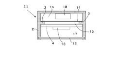
- FIG. 2 is a front sectional view showing a conceptual configuration of the illumination device 11. Since the basic structure of the illuminating device 11 is the same as that of the heat radiating device 1, common constituent elements are denoted by the same reference numerals, and description will be made focusing on portions that are different from the heat radiating device 1. Note that FIG. 2 is also a conceptual diagram, and does not accurately represent the specific shape and dimensions of the lighting device 11. Therefore, the dimensions and dimensional ratios of the illuminating device 11 and the parts constituting the illuminating device 11 cannot be read from FIG.
- the lighting device 11 is a lighting device used for fishery, for example, and has a watertight structure. That is, the housing 2 of the lighting device 11 is a cylindrical container with the top closed (that is, the cup is inverted), and the lens 12 is attached to the opening below the housing 2 in a watertight manner. It has been.
- An LED light emitting element 13 that is a light source of the illumination device 11 is disposed inside the housing 2, and light rays generated by the LED light emitting element 13 are projected to the outside of the housing 2 through the lens 12.
- the heat generated in the LED light emitting element 13 is transferred to the housing 2 through the planar heat pipe 4 and released to the outside (environment) of the housing 2. That is, the LED light emitting element 13 in the illumination device 11 corresponds to the heating element 5 in the heat dissipation device 1. It can be said that the illumination device 11 itself is a kind of heat dissipation device.
- the lighting device 11 includes a heat shielding material 14.
- the heat shielding material 14 is a cover that closes the opening 15 surrounded by the rib 3, and is mounted and fixed on the upper surface of the rib 3 (that is, the surface opposite to the surface on which the planar heat pipe 4 is mounted). 2 is divided into an upper section 16 and a lower section 17. Therefore, since the air in the lower compartment 17 heated by the heat generated by the LED light emitting element 13 does not move to the upper compartment 16, the temperature rise of the air in the upper compartment 16 is suppressed, and the device ( For example, the lighting circuit 18) of the LED light emitting element 13 is protected.
- the heat shielding material 14 is made of a material having a lower thermal conductivity than that of the housing 2.
- the ratio of the thermal conductivity between the housing 2 and the heat shielding material 14 is desirably about 5 times or more.
- the material of the housing 2 is brass, this can be realized by selecting stainless steel as the material of the heat shielding material 14.
- the thermal conductivity is approximately 1 W / (m ⁇ K) or less in the case of a general resin material, if the heat shielding material 14 is made of a resin material, the thermal conductivity of the heat shielding material 14 is changed to the housing 2.
- the heat conductivity can be sufficiently small.
- the heat resistance in the surface direction of the heat shielding material 14 becomes larger than that of the rib 3 of the housing 2, so that the heat shielding material 14 is the heat receiving portion of the planar heat pipe 4.
- the thickness is made smaller than that of the rib 3 (for example, 1/5 or less of the thickness of the rib 3). Even if it does in this way, the surface direction thermal resistance of the heat shielding material 14 becomes large compared with the rib 3 of the housing
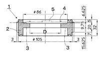
- FIG. 3 shows a model diagram of the heat dissipation device 1 used for the calculation.
- the unit of the dimension shown in the figure is mm.
- D is the diameter of the opening (corresponding to the opening 15 in FIG. 2) surrounded by the rib 3, and the calculation was performed by changing the size of D from 10 mm to 10 mm.
- the material of the housing 2 was brass, and the thermal conductivity of the planar heat pipe 4 alone was 1800 W / (m ⁇ K). It was assumed that the heating element 5 was mounted on a copper substrate. The ambient fluid was water and the environmental temperature was 25 ° C. The calorific value was 154.1W. As for the influence of buoyancy, we assumed the Boinesque approximation.
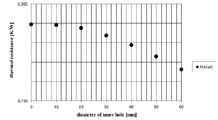
- FIG. 4 is a graph summarizing the calculation results, and shows the relationship between the diameter D of the opening and the total thermal resistance of the heat dissipation device 1.
- the horizontal axis is the diameter D (mm) of the opening
- the vertical axis is the total thermal resistance of the heat dissipation device 1, that is, the thermal resistance (K / W) between the heating element 5 and the housing 2.
- K / W thermal resistance
- the housing 2 can be reduced in weight (that is, the heat dissipation device 1 can be reduced in weight).
- the weight of the heat dissipation device can be reduced in weight.
- the housing 2 is provided with the rib 3, and the heat exhausting portion of the planar heat pipe 4 is in heat transfer contact with the rib 3.
- the heat radiating device or the lighting device according to the present invention is shown. Is not limited to those provided with ribs 3.
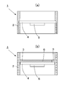
- a concave groove is formed on the inside of the housing 2, the exhaust heat portion of the planar heat pipe 4 is fitted into the concave groove, and the planar heat pipe 4 is You may make it heat-contact with a body.
- the means for connecting the planar heat pipe 4 and the housing 2 is not particularly limited. Bonding with an adhesive may be used, or mechanical fastening using screws or springs may be used. If possible, you can also choose welding or brazing. That is, any means may be selected as long as heat transfer contact can be realized. The same applies to the means for joining the heating element 5 and the planar heat pipe 4 together.
- planar heat pipe 4 was shown as a specific example of the heat transport member, the heat transport member is not limited to the planar heat pipe 4, and may be a solid heat transport member (for example, a copper plate) or various types. It may be a heat pipe (other than a planar heat pipe).
- the heat shielding material 14 is shown as a specific example of the closing member and the heat shielding material 14 is mounted and fixed on the upper surface of the rib 3, the closing member is not limited to this.
- the heat insulating material 6 may be fitted into the opening surrounded by the rib 3 so that the heat insulating material 6 contacts the upper surface of the planar heat pipe 4.
- the case 2 is formed in a cylindrical shape.
- the term “cylindrical housing” is not limited to “cylindrical”.
- the cross section of the “tube” may have any shape.
- the case 2 is made of brass, aluminum, or an aluminum alloy.
- the material of the case 2 is not limited thereto. Other metallic materials or non-metallic materials may be selected.
- the illuminating device 11 provided with the LED light emitting element 13 as a light source was shown, the application object of this invention is limited to the illuminating device which uses LED as a light source, and the heat radiator provided with LED as a heat generating body of cooling object. Not.
- the present invention can be applied to a lighting device including various light sources and a heat radiating device in which various heating elements are to be cooled.
- the heat radiating device and illuminating device which concern on this invention are not limited to the apparatus which thermally radiates in water. It may be a device that radiates heat in the air (atmosphere).
- the present invention is related to the “demonstration of low energy consumption type light and fishery by low energy consumption type high brightness and small LED underwater lighting” related to the 2011 industrial technology creation project of New Energy and Industrial Technology Development Organization. It is a product of “research”.
- the present invention is useful as a heat radiating device that discharges heat generated from a heating element disposed inside a housing to the environment. Moreover, it is useful as an illuminating device which discharges
Landscapes
- Engineering & Computer Science (AREA)
- General Engineering & Computer Science (AREA)
- Arrangement Of Elements, Cooling, Sealing, Or The Like Of Lighting Devices (AREA)
- Non-Portable Lighting Devices Or Systems Thereof (AREA)
- Cooling Or The Like Of Electrical Apparatus (AREA)
- Led Device Packages (AREA)
Abstract
放熱装置(1)は、筐体(2)と、筐体(2)の内部に配置された発熱体(5)と、発熱体(5)から発生する熱を筐体(2)に輸送する面状ヒートパイプ(4)を備えて、面状ヒートパイプ(4)は受熱部と排熱部を有して、受熱部で発熱体(5)と伝熱的に接触し、排熱部で筐体(2)と伝熱的に接触するとともに、排熱部以外の部位は筐体(2)から離隔される。
Description
本発明は、放熱装置、特に、筐体の内部に配置された発熱体から発生する熱を筐体に輸送して、該筐体から環境に排出する放熱装置に関する。また筐体の内部に配置された光源から発生する熱を筐体に輸送して、該筐体から環境に排出する照明装置に関する。
筐体の内部に、例えばLEDのような発光素子を配置した照明装置が知られている。LEDは、例えば白熱電球のような、伝統的な光源に比べて発光効率が高い、つまり発光量に比べて発熱量が小さいが、なお無視できない熱量が発生する。そのため、LEDを光源として使用する照明装置であっても、発光素子から発生する熱を環境に排出する放熱装置が必要とされる。
また、屋外あるいは水中で使用する照明装置の場合、風雨密あるいは水密に構成された筐体の中に光源を配置する必要があるが、このような照明装置にあっては、光源で発生した熱を速やかに筐体に輸送して、筐体の表面から環境に排出する放熱装置が必要とされる。
例えば、特許文献1には、光学部材と放熱ケース部材を合わせて筐体を構成して、該筐体の内部に発光素子(LED)を配置して、発光素子が発する光線を、光学部材を通して外部に投射する照明ユニットが開示されている。この照明ユニットにおいては、発光素子は基板上に配設され、基板は放熱ケース部材の前面に設けられた基板実装面に接着部材を介して接着されている。このように構成されているので、発光素子で発生した熱は基板と接着部材を通って放熱ケース部材に伝達され、放熱ケースから環境へ放出される。また、特許文献1には、放熱ケース部材を、熱伝導性に優れた材料、例えば、アルミニウム合金等の金属材料で形成されることが記載されている。
また、特許文献2には、椀形の筐体の底部にLED発光素子を配置したLED照明装置が開示されていて、ポリブチレンテレフタレート等の熱可塑性樹脂、酸化アルミニウム等の無機系フィラー、及びガラス繊維等を含有する熱可塑性樹脂成形体を筐体とすることが記載されている。この熱可塑性樹脂成形体は軽量である上に、熱伝導性に優れているので、LEDで発生した熱を効率良く環境へ放出できる。
特許文献1及び特許文献2に開示された照明装置は、照明装置の筐体自体をヒートシンクとして利用して放熱装置を構成しているので、別途ヒートシンクを備える必要がない。そのため照明装置(放熱装置)をコンパクトに纏めることができる。しかしながら、発熱体(LED発光素子)を筐体の内部において筐体と接触させる必要があるので、筐体の形状設計の自由度が低下するという問題がある。また、筐体の内部から筐体の外郭に熱を輸送する熱輸送部材の役割を筐体自身が担うので、結果として筐体が重くなるという問題がある。
本発明は、以上のような背景に鑑みてなされたものであり、筐体の内部に配置された発熱体から発生する熱を筐体に輸送して、該筐体から環境に排出する放熱装置であって、筐体の形状設計の自由度が大きく、筐体を軽量化できる放熱装置を提供することを目的とする。また、光源で発生する熱を速やかに排出できる照明装置を提供することを目的とする。
上記目的を達成するため、本発明に係る放熱装置は、筐体と、前記筐体の内部に配置された発熱体と、前記発熱体から発生する熱を前記筐体に輸送する熱輸送部材を備えて、前記発熱体から発生する熱を環境に排出する放熱装置において、前記熱輸送部材は受熱部と排熱部を有して、前記受熱部で前記発熱体と伝熱的に接触し、前記排熱部で前記筐体と伝熱的に接触するとともに、前記排熱部以外の部位が前記筐体から離隔するように構成されていることを特徴とする。
前記筐体は筒状に、前記熱輸送部材は平板状に、それぞれ形成されて、前記熱輸送部材は平板の外縁において、前記筐体の内面に伝熱的に接触しているようにしてもよい。
また、前記筐体は内面に突出する環状部材を有し、前記熱輸送部材は平板の外縁の全周において、前記環状部材に伝熱的に接触しているようにしてもよい。
さらに、前記筐体の内部の前記環状部材に取り囲まれた開口を、前記環状部材の前記熱輸送部材が取付けられた面の反対面において、閉塞する閉塞部材を備えるようにしてもよい。
さらにまた、前記閉塞部材は、前記筐体の素材に比べて、熱伝導率の小さい素材で構成されているようにしてもよい。
本発明に係る照明装置は、前述の放熱装置を備えるとともに、前記発熱体は発光素子であって、前記発光素子が発する光線を前記筐体の外部に放出することを特徴とする。
なお、本発明に係る放熱装置は、本体装置(例えば、照明装置)に装着されて、本体装置から発生する熱を環境に排出する装置には限定されない。本体装置自体が放熱装置として機能するように構成された装置も本発明に係る放熱装置に含まれる。例えば、光源で発生した熱を筐体の表面から環境に排出して光源を冷却するように構成された照明装置は本発明に係る放熱装置に該当する。
本発明によれば、発熱体から発生する熱を筐体に輸送する熱輸送部材を備えるので、筐体の形状を設計する上での制約が小さくなる。
また、熱輸送部材の排熱部以外の部位が前記筐体から離隔されるように構成されているので、熱輸送部材の受熱部と排熱部の間の温度差を大きく保つことができる。また、熱輸送部材以外の部材、熱伝導率が悪い部材に熱が流入しないので熱抵抗が低減する。そのため、放熱装置の性能を向上させることができる。また、放熱装置を軽量化できる。
また、筐体を筒状に、熱輸送部材を平板状に、それぞれ形成して、熱輸送部材が平板の外縁において筐体の内面に伝熱的に接触するように構成すれば、筐体の高さ(厚さ)を小さくできるので、放熱装置をさらに軽量化できる。
また、筐体の内面に突出する環状部材を備えて、熱輸送部材が平板の外縁の全周において、環状部材に伝熱的に接触するようにすれば、熱輸送部材の排熱部と筐体が接触する面積を最大化できるので、放熱装置の性能が向上する。その結果、放熱装置をさらに小型化できる。
また、筐体の内部の環状部材に取り囲まれた開口を、環状部材の熱輸送部材が取付けられた面の反対面において閉塞する閉塞部材を備えれば、発熱体が配置された空間と他の空間を分離できるので、例えば、熱に弱い部品等を筐体内部に配置する場合に都合がよい。
また、前記閉塞部材を筐体の素材に比べて熱伝導率の小さい素材で構成すれば、熱輸送部材の受熱部と排熱部の間の温度差を大きく保てるので、放熱装置の性能が向上する。
また、本発明に係るいずれかの放熱装置を備えて照明装置を構成すれば、照明装置の外形の設計の自由度を大きくするとともに、照明装置を軽量化することができる。
以下、本発明の実施形態について、図面を参照しながら説明する。
本発明に係る放熱装置1の概念的な構成を図1に示す。なお、図1は概念図であって、放熱装置1の具体的な形状や寸法を正確に表現したものではない。したがって、図1から放熱装置1及び放熱装置1を構成する部品の寸法や寸法比率を読み取ることはできない。
放熱装置1の筐体2は、全体として円筒形をなしていて、円筒の高さ方向の中央部には、リブ3が形成されている。リブ3は筐体2の内面に突出する環状部材であって、筐体2の内面の全周(平面図において、全円周)に形成されている。また、筐体2は放熱装置1の外郭を形成して、放熱装置1の内部空間と外部空間(環境)を区画するとともに、放熱装置1の他の部品(面状ヒートパイプ4と発熱体5)を前記内部空間に保持する部品である。
後述するように、筐体2は発熱体5から発生する熱を環境に放出する一種のヒートシンクとして機能するから、筐体2の素材には熱伝導性のよい材料が選ばれる。例えば、黄銅は熱伝導性と耐食性に優れているから、筐体2を黄銅で構成すれば、放熱装置1を屋外で使用する場合に都合がよい。また、筐体2をアルミニウムあるいはアルミニウム合金で構成すれば、放熱装置1を軽量化することができる。
面状ヒートパイプ4は、平面図において円形をなす円板状のヒートパイプである。面状ヒートパイプ4の内部には冷媒が充填されるとともに、吸熱して気化した冷媒蒸気が拡散する蒸気拡散流路(図示せず)と、放熱して凝縮した冷媒液が帰還する毛細管(図示せず)を備える。面状ヒートパイプ4は、このように構成されているので、冷媒の状態変化によって吸熱と放熱を行い、吸熱部位と放熱部位の間を冷媒が循環して熱を輸送する熱輸送部材として機能する。本実施形態では、円板の中心部が吸熱部位となり円周部分が放熱部位になるように面状ヒートパイプ4を構成している。面状ヒートパイプ4の吸熱部位(円板の中心部)には、発熱体5が装着固定され面状ヒートパイプ4と伝熱的に接触している。また、面状ヒートパイプ4は放熱部位(円板の円周部分)において筐体2に装着固定されリブ3に伝熱的に接触している。
発熱体5で発生した熱は面状ヒートパイプ4の吸熱部位(円板の中心部)において受熱され、放熱部位(円板の円周部分)で排熱されて、筐体2に伝熱され、筐体2の外表面が環境に放出される。つまり、面状ヒートパイプ4の吸熱部位(円板の中心部)が熱輸送部材の受熱部に相当し、放熱部位(円板の円周部分)が排熱部に相当する。
なお、面状ヒートパイプ4の放熱部位の面積を吸熱部位の面積より大きくすれば、発熱体5から吸熱部位に流れる熱流束に比べて、放熱部位から筐体2へ流れる熱流束を小さくできる。これにより、放熱部位から筐体2への熱伝導によって生じる筐体2、特にリブ3の温度上昇が抑制され、その結果、発熱体5の温度上昇が抑制される。
なお、面状ヒートパイプ4は既に周知の装置であるので、詳細な説明は省略する。必要ならば、例えば、日本特許第4112602号公報等を参照されたい。
発熱体5は、放熱装置1によって放熱される冷却対象物である。発熱体5は、動作中に熱が発生する装置や素子であれば、何でもよい。つまり、放熱装置1の冷却対象物は特に限定されない。
もっとも、本発明は筐体の内部に光源を密封配置した照明装置において、光源を冷却する装置として特に有用である。そこで、本発明の別の実施形態として、照明装置11の構成を説明する。
図2は照明装置11の概念的な構成を示す正断面図である。照明装置11の基本的な構成は放熱装置1と共通するので、共通する構成要素には、同一の符号を付して、放熱装置1と相違する部分を中心に説明する。なお、図2も概念図であって、照明装置11の具体的な形状や寸法を正確に表現したものではない。したがって、図2から照明装置11及び照明装置11を構成する部品の寸法や寸法比率を読み取ることはできない。
照明装置11は、例えば漁業に使用される照明器具であって、水密構造を備えている。すなわち、照明装置11の筐体2は、上方が閉じられた円筒状の(つまり、コップを逆さにしたような)容器であって、筐体2の下方の開口にはレンズ12が水密に取り付けられている。筐体2の内部には照明装置11の光源であるLED発光素子13が配置され、LED発光素子13で発生する光線は、レンズ12を通して筐体2の外部に投射される。LED発光素子13で発生する熱は、面状ヒートパイプ4を通って筐体2に伝熱され、筐体2の外部(環境)に放出される。つまり、照明装置11におけるLED発光素子13は放熱装置1における発熱体5に相当する。照明装置11自体が一種の放熱装置であるとも言える。
また、照明装置11は熱遮蔽材14を備える。熱遮蔽材14はリブ3に囲まれた開口15を閉塞するカバーであって、リブ3の上面(つまり、面状ヒートパイプ4が装着される面の反対面)に装着固定されて、筐体2の内部を上部区画16と下部区画17に分割している。そのため、LED発光素子13で発生する熱で昇温した下部区画17内の空気が上部区画16に移動しないので、上部区画16内の空気の昇温が抑制されて、上部区画16内の装置(例えば、LED発光素子13の点灯回路18)が保護される。
また、熱遮蔽材14は筐体2に比べて熱伝導率が小さい材料で構成される。筐体2と熱遮蔽材14の熱伝導率の比率は5倍程度以上であることが望ましい。例えば、筐体2の素材が黄銅である場合に、熱遮蔽材14の素材にステンレスを選べば、これを実現できる。また、一般的な樹脂素材であれば、熱伝導率は概略1W/(m・K)以下なので、熱遮蔽材14を樹脂素材で構成すれば、熱遮蔽材14の熱伝導率を筐体2の熱伝導率に比べて充分小さくできる。熱遮蔽材14の材料をこのように選べば、熱遮蔽材14の面方向熱抵抗は筐体2のリブ3に比べて大きくなるので、熱遮蔽材14は、面状ヒートパイプ4の受熱部と排熱部の間の熱勾配に殆ど影響を与えない。そのため、熱遮蔽材14を備えても、面状ヒートパイプ4による熱輸送の能率は低下しない。
また、熱遮蔽材14を筐体2と同じ材料で構成する場合には、リブ3に比べて厚さを小さく(例えば、リブ3の厚さの5分の1以下に)する。このようにしても、熱遮蔽材14の面方向熱抵抗は筐体2のリブ3に比べて大きくなる。そのため、熱遮蔽材14を備えても、面状ヒートパイプ4による熱輸送の能率は低下しない。
最後に本発明の効果を確認するために行った計算結果について説明する。図3に計算に用いた放熱装置1のモデル図を示す。図中に示した寸法の単位はmmである。また、図3においてDは、リブ3で囲まれる開口(図2の開口15に相当)の直径であり、Dの大きさを、0mmから60mmまで、10mmで変えて計算を行なった。図3は、D=60mmとした場合の形状を示している。また、D=0mmとは開口が存在しない状態、つまり面状ヒートパイプ4の裏面全体がリブ3と接触している状態に相当する。
なお、計算においては、筐体2の材質を黄銅とし、面状ヒートパイプ4単体の熱伝導率を1800W/(m・K)と仮定した。また、発熱体5は銅製基板に実装されていると仮定した。なお、周囲流体は水であり、環境温度は25℃とした。発熱量は154.1Wとした。浮力の影響については、ブジネスク近似を仮定した。
図4は計算結果を纏めたグラフであり、開口の直径Dと放熱装置1の全熱抵抗の関係を示している。横軸は開口の直径D(mm)であり、縦軸は放熱装置1の全熱抵抗、つまり発熱体5と筐体2の間の熱抵抗(K/W)である。図4から容易に理解できるように、開口の直径Dを大きくすれば放熱装置1の全熱抵抗は小さくなる。開口の直径Dが小さい(リブ3が大きい)と面状ヒートパイプ4がリブ3と接触する面積が大きくなり、面状ヒートパイプ4からリブ3に流れる熱量が多くなり、面状ヒートパイプ4の温度が低下し、その結果、発熱体5と筐体2の間の温度勾配が小さくなるから、このような現象が発生すると考えられる。
このように、放熱装置1において開口の直径Dを大きくすれば筐体2を軽量化(つまり、放熱装置1を軽量化)することができる。一般に放熱装置の軽量化と高放熱量化はトレードオフの関係にあるが、本発明によれば、両者を同時に実現できる。
以上、本発明の具体的な実施形態を説明したが、本発明の技術的範囲はこれに限定されない。特許請求の範囲に記載した技術的思想の限りにおいて、自由に応用変形あるいは改良して実施することができる。
例えば、上記実施形態では筐体2にリブ3を備えて、面状ヒートパイプ4の排熱部がリブ3と伝熱的に接触する例を示したが、本発明に係る放熱装置あるいは照明装置はリブ3を備えるものには限定されない。例えば図5(a)に示すように、筐体2の内側に凹溝を形成して、該凹溝に面状ヒートパイプ4の排熱部が嵌合して、面状ヒートパイプ4が筐体と伝熱的に接触するようにしてもよい。
また、面状ヒートパイプ4と筐体2を結合する手段は特に限定されない。接着材による結合であってもよいし、ねじやばねを利用した機械的な締結であってもよい。もし可能ならば、溶接やロウ付けを選択することもできる。つまり、伝熱的な接触を実現できるならば、どんな手段を選択してもよい。発熱体5と面状ヒートパイプ4を結合する手段についても同様である。
また、熱輸送部材の具体例として面状ヒートパイプ4を示したが、熱輸送部材は面状ヒートパイプ4に限られない、固体熱輸送部材(例えば、銅板)であってもよいし、各種(面状ヒートパイプ以外の)ヒートパイプであってもよい。
また、閉塞部材の具体例として熱遮蔽材14を示し、熱遮蔽材14がリブ3の上面に装着固定される例を示したが、閉塞部材はこのようなものには限定されない。例えば図5(b)に示すように、リブ3に囲まれた開口に断熱材6を嵌めこんで、断熱材6が面状ヒートパイプ4の上面と当接するようにしてもよい。
また、上記実施形態において筐体2を円筒状に形成した例を示したが、本発明において「筒状の筐体」と言う場合に「筒」は「円筒」には限定されない。「筒」の横断面はどんな形状であってもよい。
また、上記実施形態においては筐体2を黄銅、アルミニウムあるいはアルミニウム合金とする例を示したが、筐体2の素材はこれらには限定されない。その他の金属材料あるいは非金属材料が選択されてもよい。
また、上記実施形態においてLED発光素子13を光源として備える照明装置11を示したが、本発明の適用対象はLEDを光源とする照明装置、LEDを冷却対象の発熱体として備える放熱装置には限定されない。各種の光源を備える照明装置、各種の発熱体を冷却対象とする放熱装置に本発明を適用できる。
また、上記実施形態においてLED発光素子13で発生する熱を水中に放出する照明装置11の例を示したが、本発明に係る放熱装置及び照明装置は水中に放熱する装置には限定されない。空中(大気)に放熱する装置であってもよい。
なお、本発明は、独立行政法人新エネルギー・産業技術総合開発機構の平成23年度先導的産業技術創出事業に係る「低エネルギー消費型高輝度・小型LED水中照明による低環境負荷型灯火漁業の実証研究」の成果物である。
本出願は2012年4月11日に出願された明細書、特許請求の範囲、図、および要約書を含む日本国特許出願2012-90531号に基づく優先権を主張するものである。この元となる特許出願の開示内容は参照により全体として本出願に含まれる。
本発明は、筐体の内部に配置された発熱体から発生する熱を環境に排出する放熱装置として有用である。また筐体の内部に配置された光源から発生する環境に排出する照明装置として有用である。
1 放熱装置
2 筐体
3 リブ
4 面状ヒートパイプ
5 発熱体
6 断熱材
11 照明装置
12 レンズ
13 LED発光素子
14 熱遮蔽材
15 開口
16 上部区画
17 下部区画
18 点灯回路
2 筐体
3 リブ
4 面状ヒートパイプ
5 発熱体
6 断熱材
11 照明装置
12 レンズ
13 LED発光素子
14 熱遮蔽材
15 開口
16 上部区画
17 下部区画
18 点灯回路
Claims (6)
- 筐体と、前記筐体の内部に配置された発熱体と、前記発熱体から発生する熱を前記筐体に輸送する熱輸送部材を備えて、前記発熱体から発生する熱を環境に排出する放熱装置において、
前記熱輸送部材は受熱部と排熱部を有して、前記受熱部で前記発熱体と伝熱的に接触し、前記排熱部で前記筐体と伝熱的に接触するとともに、前記排熱部以外の部位が前記筐体から離隔するように構成されている
ことを特徴とする放熱装置。 - 前記筐体は筒状に、前記熱輸送部材は平板状に、それぞれ形成されて、
前記熱輸送部材は平板の外縁において、前記筐体の内面に伝熱的に接触している
ことを特徴とする請求項1に記載の放熱装置。 - 前記筐体は内面に突出する環状部材を有し、
前記熱輸送部材は平板の外縁の全周において、前記環状部材に伝熱的に接触している
ことを特徴とする請求項2に記載の放熱装置。 - 前記筐体の内部の前記環状部材に取り囲まれた開口を、前記環状部材の前記熱輸送部材が取付けられた面の反対面において、閉塞する閉塞部材を備える
ことを特徴とする請求項3に記載の放熱装置。 - 前記閉塞部材は、前記筐体の素材に比べて、熱伝導率の小さい素材で構成されている
ことを特徴とする請求項4に記載の放熱装置。 - 請求項1ないし請求項5のいずれか一項に記載の放熱装置を備えるとともに、
前記発熱体は発光素子であって、前記発光素子が発する光線を前記筐体の外部に放出する
ことを特徴とする照明装置。
Applications Claiming Priority (2)
| Application Number | Priority Date | Filing Date | Title |
|---|---|---|---|
| JP2012-090531 | 2012-04-11 | ||
| JP2012090531A JP6183632B2 (ja) | 2012-04-11 | 2012-04-11 | 照明装置 |
Publications (1)
| Publication Number | Publication Date |
|---|---|
| WO2013154148A1 true WO2013154148A1 (ja) | 2013-10-17 |
Family
ID=49327706
Family Applications (1)
| Application Number | Title | Priority Date | Filing Date |
|---|---|---|---|
| PCT/JP2013/060901 Ceased WO2013154148A1 (ja) | 2012-04-11 | 2013-04-11 | 放熱装置および照明装置 |
Country Status (3)
| Country | Link |
|---|---|
| JP (1) | JP6183632B2 (ja) |
| TW (1) | TW201341716A (ja) |
| WO (1) | WO2013154148A1 (ja) |
Families Citing this family (1)
| Publication number | Priority date | Publication date | Assignee | Title |
|---|---|---|---|---|
| JP2017195514A (ja) | 2016-04-20 | 2017-10-26 | キヤノン株式会社 | 頭部装着装置および把持装置 |
Citations (3)
| Publication number | Priority date | Publication date | Assignee | Title |
|---|---|---|---|---|
| JP2011138753A (ja) * | 2009-02-04 | 2011-07-14 | Panasonic Corp | 電球形ランプ及び照明装置 |
| JP2011181252A (ja) * | 2010-02-26 | 2011-09-15 | Toshiba Lighting & Technology Corp | 照明器具 |
| JP2012015083A (ja) * | 2010-05-31 | 2012-01-19 | Sumitomo Light Metal Ind Ltd | Led電球用部材及びその製造方法 |
Family Cites Families (2)
| Publication number | Priority date | Publication date | Assignee | Title |
|---|---|---|---|---|
| US7828456B2 (en) * | 2007-10-17 | 2010-11-09 | Lsi Industries, Inc. | Roadway luminaire and methods of use |
| EP2341277B1 (en) * | 2009-09-09 | 2013-06-19 | Panasonic Corporation | Bulb-shaped lamp and lighting device |
-
2012
- 2012-04-11 JP JP2012090531A patent/JP6183632B2/ja active Active
-
2013
- 2013-04-11 TW TW102112822A patent/TW201341716A/zh unknown
- 2013-04-11 WO PCT/JP2013/060901 patent/WO2013154148A1/ja not_active Ceased
Patent Citations (4)
| Publication number | Priority date | Publication date | Assignee | Title |
|---|---|---|---|---|
| JP2011138753A (ja) * | 2009-02-04 | 2011-07-14 | Panasonic Corp | 電球形ランプ及び照明装置 |
| JP2011138749A (ja) * | 2009-02-04 | 2011-07-14 | Panasonic Corp | ランプ |
| JP2011181252A (ja) * | 2010-02-26 | 2011-09-15 | Toshiba Lighting & Technology Corp | 照明器具 |
| JP2012015083A (ja) * | 2010-05-31 | 2012-01-19 | Sumitomo Light Metal Ind Ltd | Led電球用部材及びその製造方法 |
Also Published As
| Publication number | Publication date |
|---|---|
| JP2013218968A (ja) | 2013-10-24 |
| TW201341716A (zh) | 2013-10-16 |
| JP6183632B2 (ja) | 2017-08-23 |
Similar Documents
| Publication | Publication Date | Title |
|---|---|---|
| JP5794225B2 (ja) | 発光装置の冷却システム、およびそれを用いた発光装置 | |
| US9188305B2 (en) | Cooling device for vehicle headlights | |
| US9080761B2 (en) | LED illumination lamp with heat dissipation unit | |
| US20090040760A1 (en) | Illumination device having unidirectional heat-dissipating route | |
| JP2013500560A (ja) | ランプ | |
| JP2013528901A (ja) | 液冷led照明装置 | |
| CN103423723B (zh) | 液体回流散热led灯 | |
| TW201326657A (zh) | 發光二極體燈泡 | |
| KR20150015901A (ko) | 플렉시블 기판을 이용한 자동차용 led 램프 모듈 및 그 방열 구조 | |
| JP2011175868A (ja) | 照明装置 | |
| JP2018180107A5 (ja) | ||
| JP6283357B2 (ja) | 車両用灯具 | |
| JP2014135350A (ja) | ヒートシンク | |
| JP5769307B2 (ja) | 照明装置 | |
| JP2007087765A (ja) | 光源用冷却装置、光源装置及び映像表示装置 | |
| JP2008047383A (ja) | 車両用灯具 | |
| JP6183632B2 (ja) | 照明装置 | |
| JP3167690U (ja) | 組立および固定が容易なled灯具 | |
| JP2008135260A (ja) | 車両用前照灯 | |
| JP2016162597A (ja) | 照明装置 | |
| JP2014130777A (ja) | 照明装置 | |
| JP2011044398A (ja) | Led照明装置 | |
| JP2006227087A (ja) | 光源ランプ付き機器 | |
| CN110260193B (zh) | 具有散热功能的照明装置 | |
| TWM365444U (en) | Light emitting diode lamp |
Legal Events
| Date | Code | Title | Description |
|---|---|---|---|
| 121 | Ep: the epo has been informed by wipo that ep was designated in this application |
Ref document number: 13775648 Country of ref document: EP Kind code of ref document: A1 |
|
| DPE1 | Request for preliminary examination filed after expiration of 19th month from priority date (pct application filed from 20040101) | ||
| NENP | Non-entry into the national phase |
Ref country code: DE |
|
| 122 | Ep: pct application non-entry in european phase |
Ref document number: 13775648 Country of ref document: EP Kind code of ref document: A1 |